


x
RTX100B Series
RF Signal Generators
ZZZ
Quick Start User Manual
*P071259500*
071-2595-00


xx
RTX100B Series
RF Signal Generators
ZZZ
Quick Start User Manual
www.tektronix.com
071-2595-00

Copyright © Tektronix. All rights reserved. Licensed software products are owned by Tektronix or its subsidiaries or suppliers, and are
protected by na
tional copyright laws and international treaty provisions.
Tektronix pro
previously published material. Specifications and price change privileges reserved.
TEKTRONIX and TEK are registered trademarks of Tektronix, Inc.
ducts are covered by U.S. and foreign patents, issued and pending. Information in this publication supersedes that in all
Contacting Tektronix
Tektronix, Inc.
14200 SW Karl Braun Drive
P.O. Box 500
Beaverton, OR 97077
USA
For product information, sales, service, and technical support:
In North America, call 1-800-833-9200.
Worldwide, visit www.tektronix.com to find contacts in your area.

Warranty
Tektronix warrants that this product will be free from defects in materials and workmanship for a period of one (1) year from the date of
shipment. If any such product proves defective during this warranty period, Tektronix, at its option, either will repair the defective
product without charge for parts and labor, or will provide a replacement in exchange for the defective product. Parts, modules and
replacement products used by Tektronix for warranty work may be new or reconditioned to like new performance. All replaced
parts, modules and products become the property of Tektronix.
In order to obtain service under this warranty, Customer must notify Tektronix of the defect before the expiration of the warranty period
and make suitable arrangements for the performance of service. Customer shall be responsible for packaging and shipping the
defective product to the service center designated by Tektronix, with shipping charges prepaid. Tektronix shall pay for the return of the
product to Customer if the shipment is to a location within the country in which the Tektronix service center is located. Customer shall
be responsible for paying all shipping charges, duties, taxes, and any other charges for products returned to any other locations.
This warranty shall not apply to any defect, failure or damage caused by improper use or improper or inadequate maintenance and
care. Tektronix shall not be obligated to furnish service under this warranty a) to repair damage resulting from a ttempts by personnel
other than Tektronix representatives to install, repair or service the product; b) to repair damage resulting from improper use or
connection to incompatible equipment; c) to repair any damage or malfunction caused by the use of non-Tektronix supplies; or
d) to service a product that has been modified or integrated with other products when the effect of such modification or integration
increases the time or difficulty of servicing the product.
THIS WARRANTY IS GIVEN BY TEKTRONIX WITH RESPECT TO THE PRODUCT IN LIEU OF ANY OTHER WARRANTIES,
EXPRESS OR IMPLIED. TEKTRONIX AND ITS VENDORS DISCLAIM ANY IMPLIED WARRANTIES OF MERCHANTABILITY OR
FITNESS FOR A PARTICULAR PURPOSE. TEKTRONIX’ RESPONSIBILITY TO REPAIR OR REPLACE DEFECTIVE PRODUCTS
IS THE SOLE AND E XCLU S IVE REMEDY PROVIDED TO THE CUSTOMER FOR BREACH OF THIS WARRANTY. TEKTRONIX
AND ITS VENDORS WILL NOT BE LIABLE FOR ANY INDIRECT, SPECIAL, INCIDENTAL, OR CONSEQUENTIAL DAMAGES
IRRESPECTIVE OF WHETHER TEKTRONIX OR THE VENDOR HAS ADVANCE NOTICE OF THE POSSIBILITY OF SUCH
DAMAGES.
[W2 – 15AUG04]

Warranty
Tektronix warrants that the media on which this software product is furnished and the encoding of the programs on the media will be
free from defects in materials and workmanship for a period of three (3) months from the date of shipment. If any such medium or
encoding proves defective during the warranty period, Tektronix will provide a replacement in exchange for the defective medium.
Except as to the media on which this software product is furnished, this software product is provided “as is” without warranty of any
kind, either express or implied. Tektronix does not warrant that the functions contained in this software product will meet Customer’s
requirements or that the operation of the programs will be uninterrupted or error-free.
In order to obtain service under this warranty, Customer must notify Tektronix of the defect before the expiration of the warranty
period. If Tektronix is unable to provide a replacement that is free from defects in materials and workmanship within a reasonable
time thereafter, Customer may terminate the license for this software product and return this software product and any associated
materials for credit or refund.
THIS WARRANTY IS GIVEN BY TEKTRONIX WITH RESPECT TO THE PRODUCT IN LIEU OF ANY OTHER WARRANTIES,
EXPRESS OR IMPLIED. TEKTRONIX AND ITS VENDORS DISCLAIM ANY IMPLIED WARRANTIES OF MERCHANTABILITY OR
FITNESS FOR A PARTICULAR PURPOSE. TEKTRONIX’ RESPONSIBILITY TO REPLACE DEFECTIVE MEDIA OR REFUND
CUSTOMER’S PAYMENT IS THE SOLE AND EXCLUSIVE REMEDY PROVIDED TO THE CUSTOMER FOR BREACH OF
THIS WARRANTY. TEKTRONIX AND ITS VENDORS WILL NOT BE LIABLE FOR ANY INDIRECT, SPECIAL, INCIDENTAL, OR
CONSEQUENTIAL DAMAGES IRRESPECTIVE OF WHETHER TEKTRONIX OR THE VENDO R HAS ADVANCE NOTICE OF THE
POSSIBILITY OF SUCH DAMAGES.
[W9b – 15AUG04]

IMPORTANT
READ BEFORE OPERATING EQUIPMENT
This software is provided under license from Tektronix, Inc. Retention of this program for more than thirty (30) days o r use of the
program in any
manner constitutes acceptance of the license terms.
CAREFULLY READ THE ENCLOSED SOFTWARE LICENSE AGREEMENT. If you cannot agree to the license terms,
promptly contact the nearest Tektronix Field Office for return assistance.
TEKTRONIX SOFTWARE LICENSE AGREEMENT
THE PROGRAM, OR PROGRAMS, ENCODED OR INCORPORATED WITHIN EQUIPMENT, IS FURNISHED SUBJECT TO
THE TERMS AND CONDITIONS OF THIS AGREEMENT. RETENTION OF THE PROGRAM FOR MORE THAN THIRTY DAYS
OR USE OF THE
THESE TERMS ARE NOT ACCEPTABLE, THE UNUSED PROGRAM AND ANY ACCOMPANYING DOCUMENTATION SHOULD
BE RETURNED PROMPTLY TO TEKTRONIX FOR A FULL REFUND OF THE LICENSE F E E PAID. (FOR INFORMATION
REGARDING
TEKTRONIX SALES OFFICE.).
DEFINITIONS. “Tektronix” means Tektronix, Inc., an Oregon corporation, or local Tektronix’ legal entity that is supplying the
equipment.
“Program” means the Tektronix software product (executable program and/or data) enclosed with this Agreement or included within the
equipment with which this Agreement is packed.
“Customer” means the person or organizati on in whose name the Program was ordered.
PROGRAM IN ANY MANNER WILL BE CONSIDERED ACCEPTANCE OF THE AGREEMENT TERMS. IF
THE RETURN OF PROGRAMS ENCODED OR INCORPORATED WITHIN EQUIPMENT, CONTACT THE NEAREST
E.
LICENS
a. Use the
b. If the P
c. Modify the Program or merge it with another for use on the single machine; and
d. Copy the Program for archival or backup purposes, provided that no more than one (1) such copy is permitted to exist at
Customer may:
Program on a single machine at any one time;
rogram is provided in connection with a floating-user license, the Program may be used on multiple machines
provided that the user is authorized, and the total number of users at any one time does not exceed the total number of
licensed concurrent users;
e time. If the Program is provided in connection with a floating-user license, the Program may be copied onto m ultiple
any on
machines for use by authorized users.

Each copy of the Program made by Customer must include a reproduction of any copyright notice or restrictive rights legend appearing
in or on the copy
of the Program as received from Tektronix.
Customer may n
a. Use the Progra
b. Transfer the P
the prior written consent of Tektronix, except in connection with the transfer of the equipment within which the programs are
encoded or incorporated;
c. Export or re-export, directly or indirectly, the program, any associated documentation, or the direct product thereof, to any
country to w
having jurisdiction without the prior authorization, if required, of the Office of Export Administration, Department of Commerce,
Washington, D.C. and the corresponding agency of such foreign government;
d. For object-code Programs only, reverse compile or disassemble the Program for any purpose; or
e. Copy the documentation accompanying the Program.
For Programs designed to reside on a single-machine and support one or more additional machines, either locally or remotely, without
permittin
within the definition of “single m achine”. For programs permitting the Program to be transferred to an additional machine for local
execution, a separate license shall be required for each such m achine with which the Program may be used, or each concurrent user
ed under a floating-user license.
authoriz
he Program and all copies thereof, but not the media on which the Program or copies may reside, shall be and remain with
Titletot
Tektronix or others for whom Tektronix has obtained a respective licensing right.
Customer shall pay when due all property taxes that may now or hereafter be imposed, levied or assessed with respect to the
possession or use of the Program or this license and shall file all reports required in connection with such taxes.
ot:
m on more than one machine at any one time, unless covered by a floating-user license or separate site license;
rogram to any person or organization outside of Customer or the corporation of which Customer is a part without
hich such export or re-export is restricted by law or regulation of the United States or any foreign government
g the Program to be transferred to an additional machine for local execution, the additional machines shall be considered
Any portion of the Program modified by Customer or merged with another program shall remain subject to these terms and conditions.
If the Program is acquired by or for an agency of the U.S. Government, the Program shall be considered computer software developed
ate expense and the license granted herein shall be interpreted as granting Customer restricted rights in the Program and related
at priv
documentation as defined in the applicable acquisition regulation.
THE PROGRAM MAY NOT BE USED, COPIED, MODIFIED, MERGED, OR TRANSFERRED TO ANOTHER EXCEPT AS
EXPRESSLY PERMITTED BY THESE TERMS AND CONDITIONS.
UPON TRANSFER OF ANY COPY, MODIFICATION, OR MERGED PORTION OF T HE PROGRAM, THE LICENSE GRANTED
N IS A UTOMATICALLY TERMINATED.
HEREI
TERM. The license granted herein is effective upon acceptance by Customer, and shall remain in effect until terminated as provided
herein. The license may be terminated by Customer at any time upon written notice to Tektronix. The license may be terminated
by Tektronix or any third party from whom Tektronix may have obtained a respective licensing right if Customer fails to comply with
any term or condition and such failure is not remedied within thirty (30) days after notice hereof from Tektronix or such third party.
Upon termination by either party, Customer shall return to Tektronix or destroy, the Program and all associated documentation,
together with all copies in any form.
LIMITED WARRANTY. Tektronix warrants that the media on which the Program is furnished and the encoding of the Program
he media will be free from defects in materials and workmanship for a period of three (3) months from the date of shipment. If
on t
any such medium or encoding proves defective during the warranty period, Tektronix will provide a replacement in exchange for the
defective medium. Except as to the media on which the Program is furnished, the Program is provided "as is" without warranty of

any kind, either express or implied. Tektronix does not warrant that the functions contained in the Program will meet Customer’s
requirements o
r that the operation of the Program will be uninterrupted or error-free.
In order to obt
Tektronix is unable to provide a replacement that is free from defects in materials and workmanship within a reasonable time thereafter,
Customer may terminate the license for the Program and return the Program and any associated materials for credit or refund.
THIS WARRANTY IS GIVEN BY TEKTRONIX WITH RESPECT TO THE PROGRAM IN LIEU OF ANY OTHER WARRANTIES,
EXPRESS OR IM
FITNESS FOR A PARTICULAR PURPOSE. TEKTRONIX’ RESPONSIBILITY TO REPLACE DEFECTIVE MEDIA, OR REFUND
CUSTOMER’S PAYMENT IS THE SOLE AND EXCLUSIVE REMEDY PROVIDED TO THE CUSTOMER FOR BREACH OF THIS
WARRANTY.
LIMITATION
LICENSING RIGHT BE LIABLE FOR ANY INDIRECT, SPECIAL, INCIDENTAL, OR CONSEQUENTIAL DAMAGES ARISING OUT
OF OR CONNECTED WITH CUSTOMER’S POSSESSION OR USE OF THE PROGRAM, EVEN IF TEKTRONIX OR SUCH
OTHERS HAS
ain service under this warranty, Customer must notify Tektronix of the defect before the expiration of the w arranty period. If
PLIED. TEKTRONIX AND ITS VENDORS DISCLAIM ANY IMPLIED WARRANTIES OF MERCHANTABILITY OR
OF LIABILITY, IN NO EVENT SHALL TEKTRONIX OR OTHERS FROM WHOM TEKTRONIX HAS OBTAINED A
ADVANCE NOTICE OF THE POSSIBILITY OF SUCH DAMAGES.
THIRD-PARTY DISCLAIMER. Except as expressly agreed otherwise, third parties from whom Tektronix may have obtained a
licensing right do not warrant the program, do not assume any liability with respect to its use, and do not undertake to furnish any
support or information relating thereto.
GENERAL. This Agreement contains the entire agreement between the parties with respect to the use, reproduction, and transfer of
the Progr
Neither
of Tektronix.
This Agreement and the license granted herein s hall be governed by the laws of the state of Oregon.
am.
this Agreement nor the license granted herein is assignable or transferable by Customer without the prior written consent
All questions regarding this Agreement or the license granted herein should be directed to the nearest Tektronix Sales Office.
ADDITIONAL LICENSE GRANT FOR VIDEO TEST SEQUENCES. The Software Product may include certain test patterns,
video test sequences and video clips (together “Video Test Sequences”). If so, the following terms describe Your rights to the
Video Test Sequences:
You may use, copy and modify the Video Test Sequences and display or distribute copies of individual Video Test Sequences in
connection with Your video testing activity.
You are not licensed to do any of the following:
You may not distribute the collection of Video Test Sequences, except in connection with the sale of original equipment containing
the Video Test Sequences, without prior written permission from Tektronix.
You may not permit third parties to distribute copies of the Video Test Sequences.
You may not sell, license or distribute copies of the Video Test Sequences on a standalone basis or as part of any collection,
product, or service where the primary value of th e product or service is the Video Test Sequences.
You must indemnify, hold harmless, and defend Tektronix from and against any claims or lawsuits, including attorneys’ fees, that arise
from or result from the use or distribution of Video Test Sequences as modifi ed by You.
You must include a valid copyright notice on Your products and services that include copies of the Video Test Sequences.


Table of Contents
General Safety Summary ... ... . .. . ... ... . .. . ... . .. . .. . ... . .. . .. . ... . .. . .. . ... . .. . ... ... . .. . ... ... . .. . ... . .. . ... ... . .. . ... ... . .. . ... .. iii
Compliance ............................................................................................................................ v
EMC Compliance................................................................................................................. v
Safety Compliance............................................................................................................... vi
Environmental Considerations................................................................................................. viii
Preface................................................................................................................................. ix
Key Features .....................................................................................................................ix
Documentation ...................................................................................................................x
Terms Used in This Manual. . ... . .. . ... . . .. . ... ... . ... ... . .. . ... . ... ... . ... ... . .. . ... . ... ... . .. . ... . .. . ... . .. . ... . .. . ... . .. . ... . . xi
Installation.............................................................................................................................. 1
Before Installation................................................................................................................ 1
Operating Considerations........................................................................................................ 1
Connecting to the Instrument .. . .. . .. . ... . .. . ... ... . .. . ... . .. . .. . ... . .. . ... ... . .. . ... . .. . .. . ... . .. . .. . ... . .. . ... . .. . .. . ... . .. . .. . 3
Powering on the Instrument ..................................................................................................... 4
Powering Off the Instrument..................................................................................................... 4
Functional Check. ... . .. . ... . . .. . .. . ... . .. . ... ... . .. . ... . .. . ... ... . .. . ... . .. . ... . .. . .. . ... . .. . ... ... . .. . ... . .. . ... ... . .. . ... . .. . ..5
Operation............................................................................................................................... 7
Front Panel Controls and Connectors. ... . .. . ... . .. . ... ... . .. . ... . .. . .. . ... . .. . ... . .. . ... ... . .. . ... . .. . ... ... . .. . ... . . .. . ... ... . 7
Rear Panel Connectors . ... ... . .. . ... . .. . ... . .. . ... ... . .. . ... . .. . ... . .. . ... ... . .. . ... . .. . ... . .. . ... . . .. . ... ... . .. . ... . .. . ... . .. . . 9
Windows Operations . . .. . ... ... . .. . ... . .. . ... ... . .. . ... . .. . ... . .. . ... ... . .. . ... . .. . ... ... . .. . ... . .. . ... . .. . ... ... . .. . ... ... . .. . . 12
Display Elements................................................................................................................ 12
Procedures............................................................................................................................ 20
Accessing M enu Commands . . . .. . ... ... . .. . ... . .. . ... . .. . ... ... . ... ... . .. . ... . .. . ... . .. . ... . . .. . ... ... . .. . ... . .. . ... . .. . ... . .. 20
Entering Numeric Data.......................................................................................................... 21
Selecting the Data Output Source . .. . ... ... . .. . ... ... . .. . ... . .. . ... ... . .. . ... ... . .. . ... . .. . .. . ... . .. . .. . ... . .. . .. . ... . .. . ... ... 22
Adding Jitter to PCRs ........................................................................................................... 23
Performing Continuous Recording . . ... . .. . ... ... . .. . ... . . .. . .. . ... . .. . ... ... . .. . ... . .. . ... ... . .. . ... ... . .. . ... . .. . ... ... . .. . .. 24
Saving and Loading a Preset File . . ... ... . .. . ... . .. . ... ... . .. . ... ... . .. . ... . .. . ... ... . .. . ... . . .. . .. . ... . .. . ... ... . .. . ... . .. . ... 28
Setting Ethernet Network Parameters.......................................................................................... 30
Checking Remote Command Operation ....................................................................................... 33
oring the Operating System Software..................................................................................... 35
Rest
Application Examples................................................................................................................. 37
Required Equipment . .. . ... ... . .. . ... . .. . ... ... . .. . ... . .. . .. . ... . .. . ... . .. . .. . ... . .. . ... . .. . .. . ... . .. . ... ... . .. . ... . .. . ... ... . .. 37
Outputting a Transport Stream ................................................................................................. 37
Recording a Transport Stream ................................................................................................. 39
Outputting an RF Modulated Broadcast Transport Stream. . ... ... . .. . ... . .. . ... . .. . ... ... . .. . ... . .. . ... . .. . ... ... . .. . ... . . .. . 40
IP Stress Test....................................................................................................................44
Scheduler (Option SC Only) . . ... . .. . ... ... . .. . .. . ... . .. . .. . ... . .. . ... ... . .. . ... ... . .. . .. . ... . .. . ... ... . .. . ... ... . .. . .. . ... . .. . ... ...53
Starting and Exiting Scheduler . . ... ... . .. . ... . .. . ... ... . .. . ... ... . .. . ... . .. . .. . ... . .. . .. . ... . .. . .. . ... . .. . ... ... . .. . ... ... . .. . . 53
Elements of the Scheduler Display . .. . .. . ... . .. . .. . ... . .. . ... ... . .. . ... . .. . .. . ... . .. . ... ... . .. . ... . .. . .. . ... . .. . ... ... . .. . ... . . 54
Using the Scheduler Menus .. . ... . .. . ... . .. . ... . . .. . ... ... . .. . ... . .. . ... . .. . ... ... . .. . ... . .. . ... . .. . ... ... . .. . ... . .. . ... . .. . ... 56
Status/Control Panel .. . .. . ... ... . .. . ... ... . .. . ... . .. . .. . ... . .. . .. . ... . .. . .. . ... . .. . ... ... . .. . ... ... . .. . ... . .. . ... ... . .. . ... ... . . 65
Table of Content
s
RTX100B Series RF Signal Generators Quick Start User Manual i

Table of Content
Accessories an
Index
s
Scheduler Tutorials. ... . .. . ... ... . .. . ... ... . .. . ... ... . .. . ... ... . .. . ... ... . .. . ... . .. . ... ... . .. . .. . ... . .. . .. . ... . .. . ... ... . .. . ... ..67
d Options............................................................................................................. 71
Accessories .....................................................................................................................71
Options .......................................................................................................................... 72
ii RTX100B Series RF Signal Generators Quick Start User Manual

General Safety S
ummary
General Safet
Review the following safety precautions to avoid injury and prevent damage to this product or any products connected to it.
To avoid potential hazards, use this product only as specified.
Only qualified personnel should perform service procedures.
While using this product, you may need to access other parts of a larger system. Read the safety sections of the other
component manuals for warnings and cautions related to operating the system.
To Avoid Fire or Personal Injury
Use Proper Power Cord. Use only the power cord specified for this product and certified for the country of use.
Connect and Disconnect Properly. Connect the probe output to the measurement instrument before connecting the
probe to th
input. Disconnect the probe input and the probe reference lead from the circuit under test before disconnecting the probe
from the measurement instrument.
Ground the Product. This product is grounded through the grounding conduc tor of the power cord. To avoid electric
shock, th
terminals of the product, ensure that the product is properly grounded.
Observe All Terminal Ratings. To avoid fire or shock hazard, observe all ratings and markings on the product. Consult
the product manual for further ratings information before making connections to the product.
e circuit under test. Connect the probe reference lead to the circuit under test before connecting the probe
e grounding conductor must be connected to earth ground. Before making connections to the input or output
y Summary
The inputs are not rated for connection to mains or Category II, III, or IV circuits.
Power Disconnect. The power cord disconnects the product from the power source. Do not block the power cord; it
main accessible to the user at all times.
must re
Do Not O
Do Not O
qualified service personnel.
perate Without Covers.
perate With Suspected Failures.
Do not operate this product with covers or panels removed.
If you suspect that there is damage to this product, have it inspected by
Avoid Exposed Circuitry. Do not touch exposed connections and components when power is present.
Use Proper Fuse. Use only the fuse type and rating specified for this product.
Do Not Operate in Wet/Damp Conditions.
Do Not Operate in an Explosive Atmosphere.
Keep Product Surfaces Clean and Dry.
Provide Proper Ventilation.
proper ventilation.
Refer to the manual’s installation instructions for details on installing the product so it has
RTX100B Series RF Signal Generators Quick Start User Manual iii
General Safety S
TermsinthisManual
These terms may appear in this manual:
WARNING. Warning statements identify conditions or practices that could result in injury or loss of life.
CAUTION. Caution statements identify conditions or practices that could result in damage to this product or other property.
Symbols and Terms on the Product
These terms may appear on the product:
DANGER indicates an injury hazard immediately accessible as you read the marking.
WARNING indicates an injury hazard not immediately accessible as you read the marking.
CAUTION indicates a hazard to property including the product.
The following symbol(s) may appear on the product:
ummary
iv RTX100B Series RF Signal Generators Quick Start User Manual

Compliance
This section lists the EMC (electromagnetic compliance), safety, and environmental standards with which the instrument
complies.
EMC Compliance
Compliance
EC Declarati
Meets intent of Directive 2004/108/EC for E lectromagnetic Compatibility. Compliance was demonstrated to the following
specifications as listed in the Official Journal of the European Communities:
EN 61326-1 2006. EMC requirements for electrical equipment for measurement, control, and laboratory use
CISPR 11:2003. Radiated and conducted emissions, Group 1, Class A
IEC 61000-4-2:2001. Electrostatic discharge immunity
IEC 61000-4-3:2002. RF electromagnetic field immunity
IEC 61000-4-4:2004. Electrical fast transient / burst immunity
IEC 61000-4-5:2001. Power line surge immunity
IEC 61000-4-6:2003. Conducted RF immunity
IEC 61000-4-11:2004. Voltage dips and interruptions immunity
on of Conformity – EMC
1,2
EN 61000-3-2:2006. AC power line harmonic emissions
EN 61000-3-3:1995. Voltage changes, fluctuations, and flicker
European Contact.
Tektronix UK, Ltd.
Western Peninsula
Western Road
Bracknell, RG12 1RF
United Kingdom
1
This product is intended for use in nonresidential areas only. Use in residential areas may cause electromagnetic interference.
2
Emissions which exceed the levels required by this standard may occur when this equipment is connected to a test object.
Australia / New Zealand Declaration of Conformity – EMC
Complies with the EMC provision of the Radiocommunications Act per the following standard, in accordance with ACMA:
CISPR 11:2003. Radiated and Conducted Emissions, Group 1, Class A, in accordance with EN 61326-1:2006.
RTX100B Series RF Signal Generators Quick Start User Manual v

Compliance
Safety Compliance
EC Declaration of Conformity – Low Voltage
Compliance was demonstrated to the following specification as listed in the Official Journal of the European Communities:
Low Voltage Directive 2006/95/EC.
EN 61010-1: 2001. Safety requirements for electrical equipment for measurement control and laboratory use.
U.S. Nation
UL 61010-1:2004, 2ndEdition. Standard for electrical measuring and test equipment.
ally Recognized Testing Laboratory Listing
Canadian Certification
CAN/CSA C
laboratory use. Part 1.
22.2 No. 61010-1:2004. Safety requirements for electrical equipment for measurement, control, and
Additional Compliances
IEC 61010-1: 2001. Safety requirements for electrical equipment for measurement, control, and laboratory use.
Equipment Type
Test and measuring equipment.
yClass
Safet
Class 1 – grounded product.
Pollution Degree Description
asure of the contaminants that could occur in the environment around and within a product. Typically the internal
Ame
environment inside a product is considered to be the same as the external. Products should be used only in the environment
for which they are r ated.
Pollution Degree 1. No pollution or only dry, nonconductive pollution occurs. Products in this category are generally
capsulated, hermetically sealed, or located in clean rooms.
en
llution Degree 2. Normally only dry, nonconductive pollution occurs. Occasionally a temporary conductivity that is
Po
caused by condensation must be expected. This location is a typical office/home environment. Temporary condensation
occurs only when the product is out of service.
Pollution Degree 3. Conductive pollution, or dry, nonconductive pollution that becomes conductive due to condensation.
hese are sheltered locations where neither temperature nor humidity is controlled. The area is protected from direct
T
sunshine, rain, or direct wind.
Pollution Degree 4. Pollution that generates persistent conductivity through conductive dust, rain, or snow. Typical
outdoor locations.
vi RTX100B Series RF Signal Generators Quick Start User Manual

Pollution Degree
Pollution Degree 2 (as defined in IEC 61010-1). Note: Rated for indoor use only.
Compliance
RTX100B Series RF Signal Generators Quick Start User Manual vii
Compliance
Environmental Considerations
This section provides information about the environmental impact of the product.
Product End-of-Life Handling
Observe the following guidelines when recycling an instrument or component:
Equipment Recycling. Production of this equipment required the extraction and use of natural resources. The
equipment may contain substances that could be harmful to the environment or human health if improperly handled at the
product’s end of life. In order to avoid release of such substances into the environment and to reduce the use of natural
resources, we encourage you to recycle this product in an appropriate system that will ensure that most of the materials are
reused or recycled appropriately.
Mercury Notification. This product uses an LCD backlight lamp that contains mercury. Disposal may be regulated due
to environmental considerations. Please contact your local authorities or, within the United States, the Electronics Industries
e (www.eiae.org) for disposal or recycling information.
Allianc
This symbol indicates that this product complies with the European Union’s
requirements according to Directive 2002/96/E C on waste electrical
and electronic equipment (WEEE). For information about recycling
options, check the Support/Service section of the Tektronix Web site
(www.tektronix.com).
Perchlorate Materials. This product contains one or more type CR lithium batteries. According to the state
of California, CR lithium batteries are classified as perchlorate materials and require special handling. See
www.dtsc.ca.gov/hazardouswaste/perchlorate for additional information.
Restriction of Hazardous Substances
This product has been classified as Monitoring and Control equipment, and is outside the scope of the 2002/95/EC RoHS
Directive.
viii RTX100B Series RF Signal Generators Quick Start User Manual

Preface
This manual provides operational instructions for both the RTX100B and the RTX130B products.
The RTX100B ISDB-T RF Signal Generator converts a broadcast transport stream into an RF signal and outputs it. In
addition to the RF signal output feature, the generator records and plays MPEG-2 transport streams that are compliant with
ATSC, DVB, and ARIB standards.
The RTX130B QAM & VSB RF Signal Generator generates QAM, 8VSB, and DMB-T modulated signals that are compliant
with the DVB-C/ITU-T J.83 Annex A/B/C, and ATSC standards. In addition to the RF signal output feature, the Genera
records and plays MPEG-2 transport streams that are compliant with ATSC, D VB, and ARIB standards.
NOTE. When the instrument sends or receives a stream for a long time, the stream may be intermittent because of a
processing condition of the hard disk or the Windows XP system process.
Key Features
Common Features for Both the RTX100B Generator and the RTX130B Generator
Data rate: 200 Mbps maximum (RAM mode); 256 Kbps minimum
Preface
tor
Hierarchy display of stored or captured transport streams
188, 204, 208 bytes packet size,
S-TMCC, M-TMCC, nontransport stream, and partial transport stream output formats
Real-time updating of stream parameters: continuity_counter, PCR/PTS/DTS, TOT/TDT/STT, NPT, and Reed Solomon
(ISDB-T only)
Continuous recording of captured streams
PCR jitter insertion
Triggered stream capture
Full remote control using Ethernet interface
Scheduler application for automated stream playout and record (Option SC only)
Two IP versions namely IPv4 and IPv6 are supported
Stream replication (IP) with some attributes of the stream incremented by a certain value
IP stress generation capabilities
Tclips MPEG Test Streams
Specific Features for RTX100B Generator
Play interface: IP and RF/ASI/310M interfaces
RF modulated output of broadcast transport streams
UHF: 13 channel to 62 channel (473 MHz to 767 MHz)
Direct RF output of ASI input signals
RTX100B Series RF Signal Generators Quick Start User Manual ix
Preface
Specific Features for RTX130B Generator
Play interface: IP and QAM/VSB/DMB-T
16/64/256QAM and 8VSB modulation formats
Modulation frequency range: 50 MHz to 860 MHz
44 MHz or 36 MHz IF output
Supports the following standards:
DVB-C/ITU-T J.83 Annex A (Option M1)
ITU-T J.83 Annex B (Option M2)
ITU-T J.83 Annex C (Option M3)
ATSC (Option M4)
The RTX100B Series includes the ReMux application software that provides the capability to create a transport stream of
super frame structure defined in the ISDB-S systems from an MPEG-2 transport stream.
Documentation
The follo
wing information is available for this product:
Table i: Product documentation
Item Purpose Location
RTX100B Series RF Signal Generators
tart User Manual (071-2595-xx
Quick S
English, 071-2596-xx Japanese)
RTX100B Series RF Signal Generators
Specifications and Performances
cation Technical Reference
Verifi
Manual (077-0193-xx)
RTX100B Series RF Signal
Generators Technical Reference
al (077-0192-xx)
Manu
00B Series RF Signal Generators
RTX1
Service Manual (077-0194-xx)
MTX/RTX Release Notes
-0195-xx)
(077
ips Technical Reference Manual
Tcl
(077-0074-xx)
Provides installation and
high-level operational overviews
es complete product
Provid
specifications and a procedure
for verifying the operation of the
ment
instru
des in-depth operating
Provi
information
onal manual supporting
Opti
module-level servicing of the
instrument
Provides in-depth operating
ormation
inf
x RTX100B Series RF Signal Generators Quick Start User Manual

TermsUsedinThisManual
This manual uses the following terms:
Stream: Generic term for transport streams and data streams of Non-TS format (data format other than transport
stream format).
S-TMCC (Single TMCC): Transport stream to which TMCC (Transmission and Multiplexing Configuration Control)
information is inserted into the 8 bytes in its Reed-Solomon code area (16 bytes). It is defined in the ISDB-S (Integrated
Services Digital B roadcasting-Satellite) system.
M-TMCC (Multi TMCC): Transport stream to which TMCC information is inserted into the sync byte area, and has
super frame structure. It is defined in the ISDB-S system.
Broadcast transport stream: Transport stream defined in ARIB STD-B31.
RTX130B (QAM & VSB RF Signal Generator) references in the document refer to the information that is specificto
the RTX130B instrument.
RTX100B (ISDB-T RF Signal G enerator) references in the document refer to the information that is specifictothe
RTX100B instrument.
RTX100B Series references in the document refer to information that is shared between the RTX100B generator and
the RTX130B generator.
Preface
RTX100B Series RF Signal Generators Quick Start User Manual xi

Preface
xii RTX100B Series RF Signal Generators Quick Start User Manual

Installation
Before Installation
Perform the following product inspection procedure when you receive your instrument:
1. Inspect the shipping carton for external damage, which indicates possible damage to the instrument.
2. Remove the generator from the shipping carton.
3. Check that the instrument has not been damaged in transit. The exterior should not have any scratches or impact marks.
Before shipment the instrument is thoroughly inspected for mechanical defects.
NOTE. Save the shipping carton and packaging materials for instrument repackaging in case shipment becomes necessary.
Refer to the RTX100B Series Technical Reference manual for instructions on repackaging the instrument.
4. Verify that the shipping carton contains the instrument, the standard accessories, and any optional accessories that
you ordered. (See page 71, Accessories and Options.)
5. Perform the functional check procedure after installing the instrument. (See page 5, Functional Check.)
Installation
Contact your local Tektronix Field Office or representative if there is a problem with your instrument or if your shipment is
incomplete.
Operating Considerations
Before you install the instrument, refer to the General Safety Summary section at the front of this manual for power source,
ing, and other safety information.
ground
Environment Operating Requirements
Verify that the location of your installation has the proper operating environment. Refer to the following table:
CAUTION. Damage to the instrument can occur if this instrument is powered on at temperatures outside of the specified
temperature range.
Table 1: Environmental operating requirements
Characteristics Specifications
Ambient temperatures
Relative humidity
Maximum operating altitude 3000 m
Clearance on top 5.0 cm (2 in)
Clearance on left side 5.0 cm (2 in)
Clearance on right side 5.0 cm (2 in)
From +5 °C to +40 °C
From 20% to 80%
RTX100B Series RF Signal Generators Quick Start User Manual 1
Installation
Table 1: Environmental operating requirements (cont.)
Characteristics Specifications
Clearance in rear (from the fan guard) 5.0 cm (2 in)
NOTE. If you are installing the instrument in a dedicated rack, refer to the instruction sheet that comes with the rack
mounting kit for proper installation procedures. When the generator is mounted in a 19-inch rack, verify that there is at least
one unit of clearance above the generator.
AC Line Voltage Requirement
Check that your location provides the proper electrical power requirements. Refer to the following table.
Table 2:
Paramet
Line voltage range 100 to 240 V
Line frequency 50/60 Hz
Maximum power 180 VA
CAUTI
power cable to the AC line connector, power is applied to the power supply standby circuit of the instrument. Read the power
application instructions before plugging the power cable into a power source. (See page 4, Powering on the Instrument.)
AC line power requirement
er
ON. The instrument does not have a power switch, but does have an on/standby switch. W hen you connect the
Descrip
tion
Power Cord Requirement
Verify that you are using the proper power cord for your location. (See Table 18 on page 72.) Connect the power cord
from the rear-panel power connector to the power system.
CAUTION. The instrument is shipped with a power cord appropriate for use with your power systems (normal 115 V power
system or 230 V power system). If the instrument is to be used with a power system other than that specified in the order, the
power cord must be replaced with one appropriate for the power source used.
2 RTX100B Series RF Signal Generators Quick Start User Manual
Connecting to the Instrument
Refer to Rear Panel Connectors for i nformation about connecting to the instrument. (See page 9.)
Connecting the RTX100B Series Generator to a PC
The generator uses the rear-panel LAN port to communicate with a PC or MTS400.
Use one of the following methods to connect the generator to your PC or MTS400:
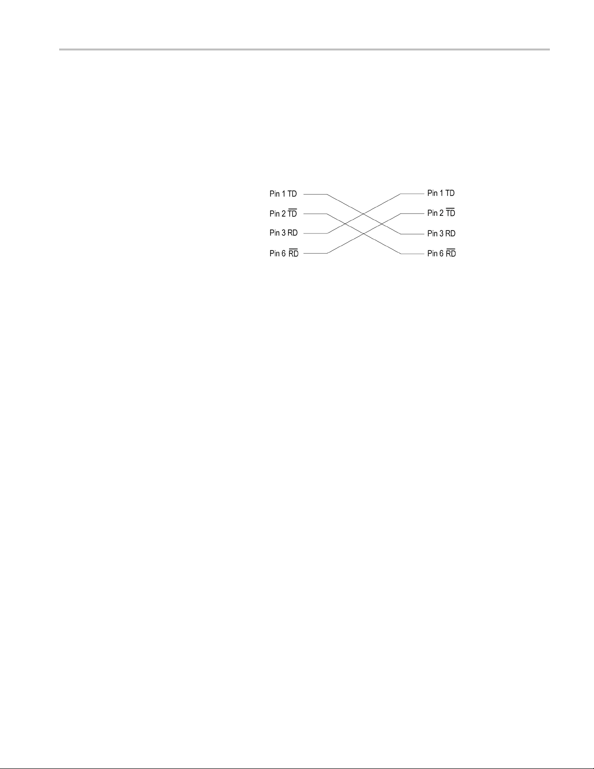
Installation
1. If you are co
directly to a single PC, use a crossover
Ethernet cable to connect between
the LAN por
Ethernet port on the PC. If you need
to construct your own crossover cable,
change the
cable as shown in the figure to product
a crossover cable.
2. If you are connecting the generator
to your l
a straight Ethernet cable to connect
between the LAN port on the generator
and the E
network. By connecting to an Ethernet
network, you can access the generator
using a
nnecting the generator
t on the generator and the
pin connections on a straight
ocal Ethernet network, use
thernet hub port of your local
ny PC on the network.
RTX100B Series RF Signal Generators Quick Start User Manual 3
Installation
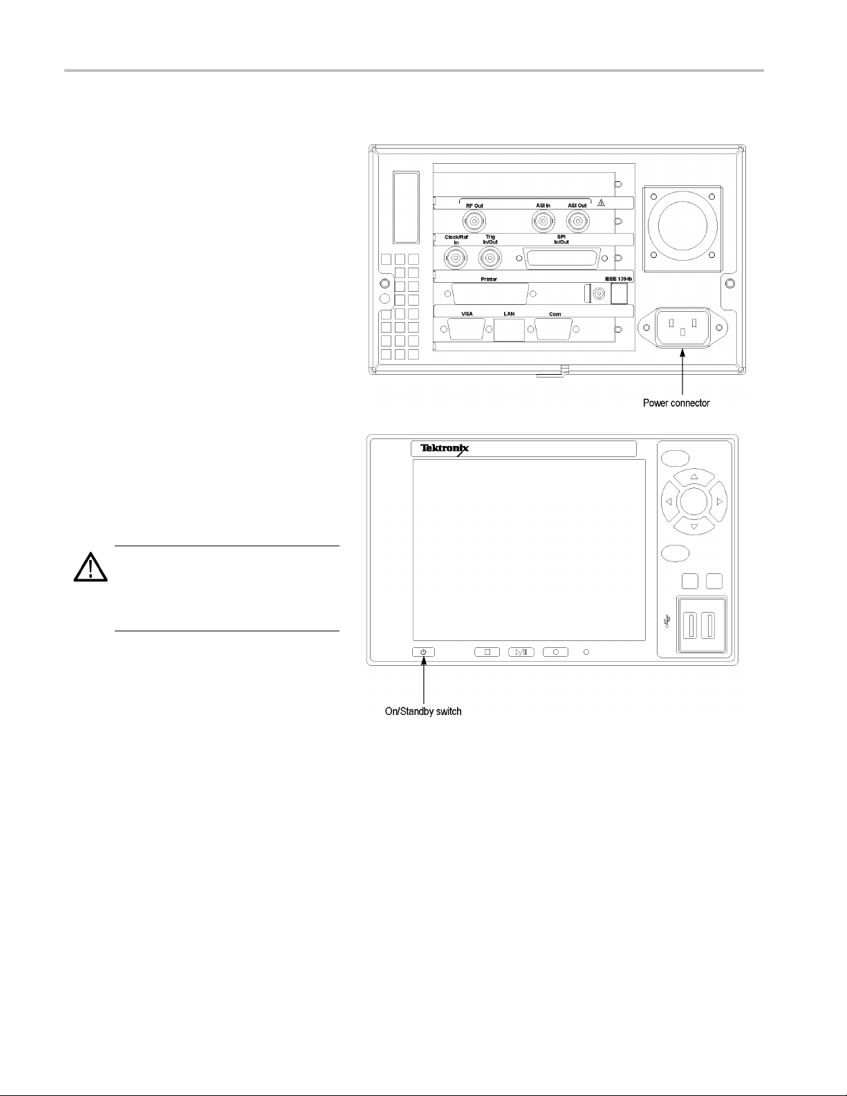
Powering on the Instrument
1. After you have verified the operating
environment,
requirements, plug the power cord into
the power connector on the rear panel,
and then plug
local power source.
2. Press the On/Standby switch to power
on the instrument. After you power on
the instr
rear panel is operating. To verify that the
fan is operating, place your hand behind
the righ
should be able to feel the fan’s air flow.
AC line, and power cord
the power cord into the
ument, verify that the fan on the
t side of the instrument. You
CAUTION. Do not operate the instrument if
ing fan does not operate w hen you
the cool
turn on the instrument. Serious damage to
your instrument can occur from overheating
ooling fan is not operating
if the c
Powering Off the Instrument
Always power off the instrument using the Windows XP shutdown process (select Start > Shut down…orStart > Turn
off computer). The system (including applications) will shut down automatically. When prompted, push the front panel
tandby switch to remove power from the unit.
On/S
ernatively, push the front panel On/Standby switch for two seconds and release. The system will shut down and power
Alt
off automatically with no further intervention.
4 RTX100B Series RF Signal Generators Quick Start User Manual
Functional Check
Perform the following procedure if you are operating the instrument for the first time (to verify that the instrument shipped
without damage) or if you suspect that the instrument is not working properly.
1. Connect the generator to a power
source, and then turn on the instrument
using the On/Standby switch.
2. Press the front-panel Menu button to
display the File menu command list.
NOTE. Ensure that a dongle is connected
and a valid option key has been provided
using Option Wizard.
3. Press the up (▲)ordown(▼)arrow
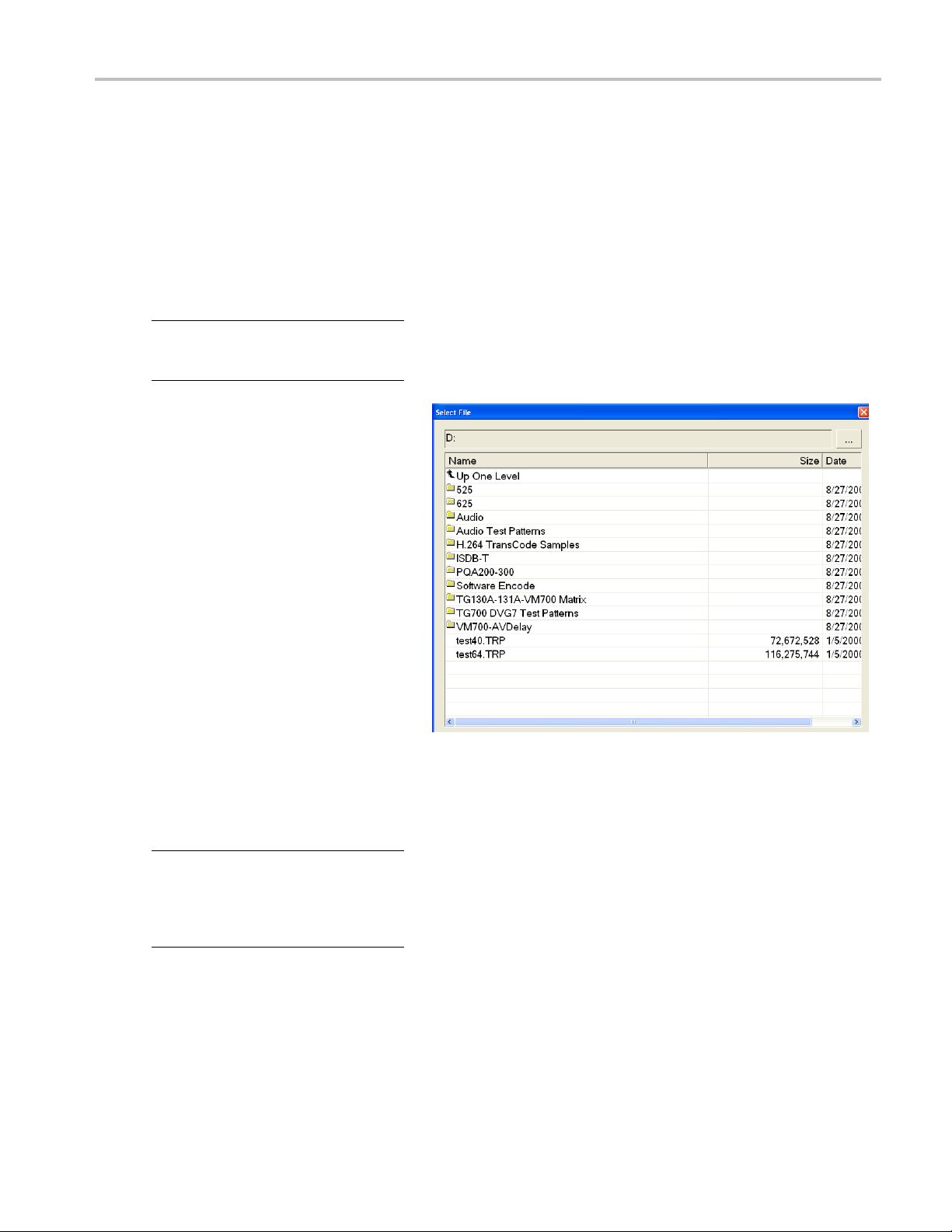
button to select Open from the list, and
then press the Enter button to open the
Select File dialog box.
Installation
4. Press the up (▲)ordown(▼)arrow
button to select the test64.TRP file,
and then press the Enter button. The
hierarchy view of the transport stream
file will be displayed on the screen.
NOTE. You can select the test40.TRP file
in step 4 of this procedure if you need to
decrease the bit rate of the transport stream
due to performance restrictions in your
decoder.
5. Connect the interface cable provided
with the instrument between the SPI
In/Out connector on the generator rear
panel and the SPI In connector on an
MPEG decoder.
RTX100B Series RF Signal Generators Quick Start User Manual 5
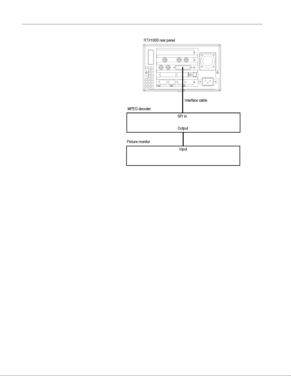
Installation
6. Connect the decoder to a picture monitor.
7. Press the generator Play/Pause button
to start the transport stream output.
When transpor
t s tream output is started,
the Play Status indicator appears on the
screen.
8. Check that the picture from the transport
stream is dis
played correctly on the
picture monitor.
6 RTX100B Series RF Signal Generators Quick Start User Manual
Operation
This section gives you a functional overview and provides descriptions of basic menu operations for the generator. For more
detailed operating instructions and descriptions of the generator interface and controls, refer to the RTX100B Series RF
Signal Generators Technical Reference manual.
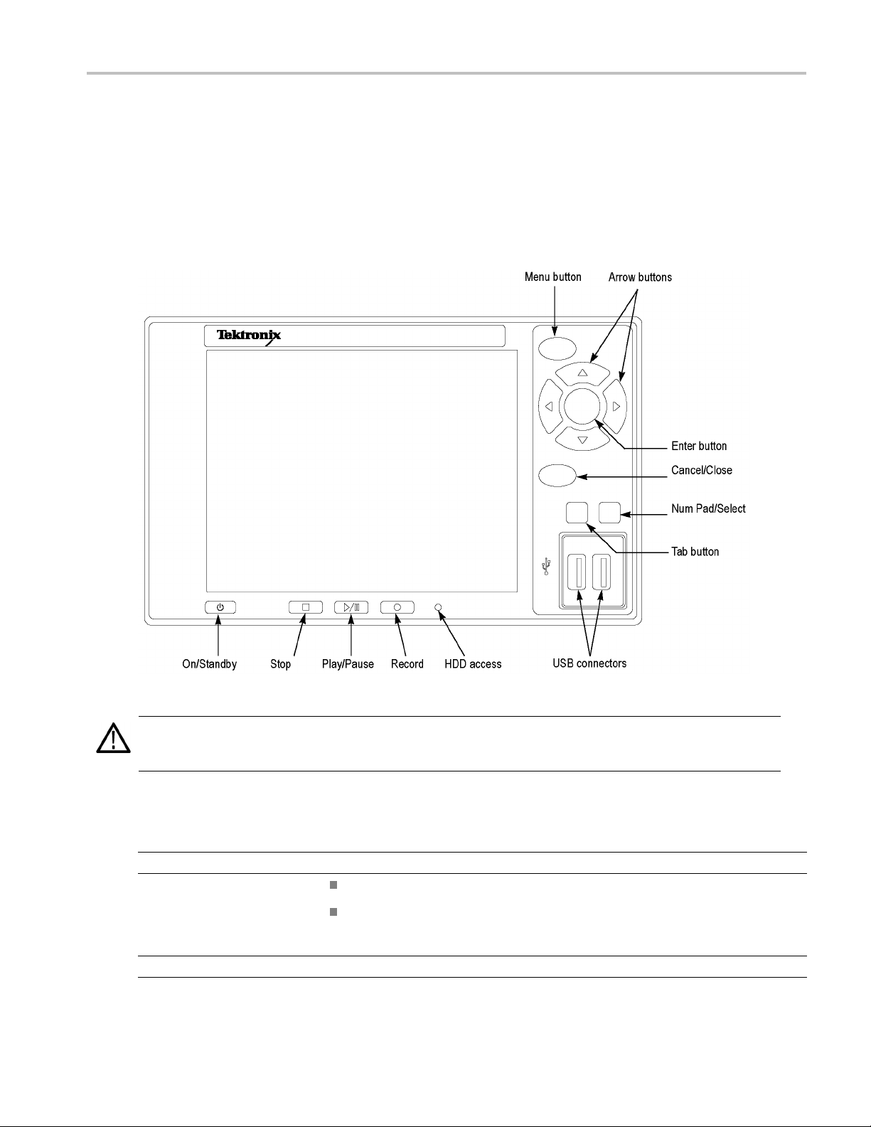
Front Panel Controls and Connectors
Operation
CAUTION. If you power off the instrument using the On/Standby switch, the current instrument settings are not saved (this
operation corresponds to an emergency shutdown in Windows XP). To prevent data loss, use the Shutdown command
from the File menu to power off the instrument.
Table 3: Front panel controls and connectors
Button Function
On/Standby Switch Powers on or off the instrument.
Stop Button
HDD Access Indicator Indicator illuminates when the hard disk drive is in operation.
RTX100B Series RF Signal Generators Quick Start User Manual 7
If you press this button while a stream data is being output, the data output stops.
If you press this button while the pretrigger portion is fi lled and the instrument waits
for a trigger event or the posttrigger portion is being recorded, the recorded data
is stored in a file.

Operation
Table 3: Front panel controls and connectors (cont.)
Button Function
Menu Button
Play/Pause Button
Record Button Press this button to record the stream data that is being applied.
Toggles the display of the menu command list on or off.
Press this button to output the data.
If you press this button the Record screen is displayed, it switches to the Play
screen.
If you press this button while a stream data is being output, the data output pauses.
Press the button again to start the stream output.
When an M-TMCC transport stream is selected, generator outputs the stream from
the start packet in the super frame to the maximum number of packets that can be
looped as an integral multiple of the number of super frames. When an ISDB-T
transport stream is selected, generator outputs the stream from the start packet in
the OFDM (Orthogonal Frequency Division Multiplexing) frame to the maximum
number of packets that can be looped as 2 X N of the number of OFDM frames.
If any of the transport s treams within the ISDB-T transport stream have different
modulation parameters, select Non-TS from the Packet Size command in the Play
menu.
The status i ndicator light in the button illuminates when stream data is being output.
The light blinks when the stream output pauses.
If you press this button while the Play screen is displayed, it switches to the Record
screen.
Press this button to start the RF output of the modulated signal when a broadcast
transport stream is applied to the ASI In connector.
The status indicator light in the button blinks when a sync word is being detected, or
when the pretrigger portion of the stream data has been recorded.
Arrow Buttons
Enter Button Executes the selected menu command or enable all setting changes in a dialog box.
Cancel/Close Button Cancels the selected operation and closes any open menu command list temporarily.
Tab Button Moves through the dialog box.
Num Pad/Select Button
USB Connectors Connects the keyboard and mouse provided with the instrument for Windows operations.
Move the icon cursor on the LCD display.
Enables or disables any setting changes in a dialog box. You can also open the keypad
to enter numeric values for a text box.
When an ISDB-T file is selected in the Play screen or an ISDB-T signal is captured in the
Record screen, pressing this button causes the ISDB-T Information dialog box to appear.
8 RTX100B Series RF Signal Generators Quick Start User Manual

Rear Panel Connectors
Operation
Figure 1:
RTX130B rear panel
RTX100B Series RF Signal Generators Quick Start User Manual 9

Operation
Figure 2: RTX100B rear panel
Table 4
Connector Function
RF Out Output an RF signal.
ASI I
ASI O
Clo
Trig In/Out Input an external trigger event for stream recording or output a 27 MHz reference
SPI In/Out Input and Output an SPI signal.
Printer
IEEE1394b
LAN(10/100/1000 Base-T)
Com This 9-pin D-sub connector provides a serial interface for instrument control.
: Rear panel connectors
n
ut
ck/Ref In
NOTE. The RF signal output is only available when a broadcast transport stream
ng output or applied.
is bei
t an ASI signal.
Inpu
ut an ASI signal.
Outp
ut an external reference signal or a clock signal to the generator.
Inp
NOTE. Use a continuous signal for an external reference or a clock signal.
clock signal or an ISDB-T frame pulse signal.
Connect to a printer.
Connect an IEEE 1394b device such as an external hard disk drive.
Use this connector to connect the generator to your local Ethernet network.
10 RTX100B Series RF Signal Generators Quick Start User Manual

Table 4: R ear panel connectors (cont.)
Connector Function
VGA
Power Connector
Display the instrument screen to an external monitor.
The VGA output is automatically enabled only when you power on the instrument
with an external monitor connected. If you want to enable the VGA output after
powering on the instrument, perform the following steps:
1. Minimize the Play screen to display the Windows XP desktop.
2. Click the Intel(R) Extreme Graphics 2M icon (see below) at the right side of
the taskbar.
3. Select Graphic Options > Output To > Intel(R) Dual Display Clone >
Monitor+Notebook from the displayed menu.
Use this connector to apply power to the instrument using the supplied power
cord.
Operation
RTX100B Series RF Signal Generators Quick Start User Manual 11

Operation
Windows Operations
All the functions of the generator are performed as an application on the Windows XP operating system. Therefore, if you
connect the keyboard and mouse provided with the instrument to the front-panel USB connectors, you can operate the
generator with the same environment as a Windows PC.
Operation on the Play/Record Screen
When you connect a keyboard and mouse to the instrument, you can use them to make menu selections and parameter
settings in the Play/Record screen. These operations behave in the same manner as the other Windows applications.
Displayin
To display the Windows screen (Desktop), select Minimize or Exit from the File menu in the Play screen or Record screen.
When you click Minimize, the generator application window minimizes and the Windows XP desktop appears. When you
click Exit, the generator application exits and the Windows XP desktop appears.
g the Windows Screen (Desktop)
File Operation
There are no menu commands to manage file operations in the generator application. Perform file operations such as copy,
or upload/download on Windows. Refer to Windows XP O nline Help or other documentation about file operations.
delete,
The gen
files are placed on the D: drive (Volume D).
erator application is placed in the C:\ProgramFiles\Tektronix\MpegPlayer folder. The sample transport stream
System Settings
This manual describes only the settings for connecting to an Ethernet network. Refer to Windows XP Online Help or other
documentation for information about other system settings.
Display Elements
e are two types of display screens to operate the generator: the Play screen and the Record screen.
Ther
Play screen is used to output the selected stream.
The
Record screen is used to record the input stream.
The
NOTE. When you press the REC/Play button or select the Record/Play command from the File menu while the Play/Record
screen is displayed, the screen switches to the Record/Play screen.
12 RTX100B Series RF Signal Generators Quick Start User Manual

Operation
The following figure shows the location of display elements of the Play screen. The display elements of the Record screen
are the same as t
hat of the Play screen.
Menu Bar
Menu bar displays the names of the menus that can be used in the Play or Record screen. Press the Menu button to
The
enable or disable the menus.
RTX100B Series RF Signal Generators Quick Start User Manual 13

Operation
Toolbar
The toolbar provides shortcut buttons for many of the most often used menu commands. Click a toolbar button to select the
corresponding command. You can toggle the toolbar display on and off using the Toolbar command in the View m enu.
Hierarchy Display
Eachiconint
associated icon.
he hierarchy display represents an element of the stream. The hierarchy text contains a description of the
Icon Cursor. The icon cursor appears as a red box around an icon in the hierarchy to indicate the currently selected icon.
Use the up (▲)ordown(▼) arrow button to move the icon cursor between icons. When the icon cursor is at the top or
bottom of the hierarchy display, the hierarchy scrolls to show additional elements of the stream when applicable.
Play/Record Status Indicator
The play/record status indicator is displayed while the selected stream is being output as shown in the following figure. It
shows the output status of the selected stream: the progress of the stream output, the output source, the operational
status, a
The play
of the input stream: the progress of the stream record, the record target, and the elapsed time.
nd the elapsed time.
/record status indicator is displayed while the input stream is being played/recorded. It shows the play/record status
The play/record status indicator shows the following information:
1. Position Indicator. In the Play screen, this indicator shows the progress of the stream output using the duration gauge.
In the Record screen, this indicator shows the progress of the stream record using the duration gauge.
The duration gauge is updated every 1 second. If you output a stream with a repetition rate of around 3 seconds,
the gauge might not be displayed correctly.
2. Output Source/Record Target. In the Play screen, this indicator shows the output source used to output the selected
stream. In the Record screen, this indicator shows the record target used to record the input stream. show the current
operation status of the instrument. One of the icons mentioned under Output Source/Record Target in the following table
is displayed according to the selected output source or record target. (See Table 5.)
14 RTX100B Series RF Signal Generators Quick Start User Manual

3. Operation Status. Shows the current operation status of the instrument.
Table 5: Operation status icons
Icon Description
Output Source/Record Target
This icon shows that the hard disk i s the output source or record target.
This icon shows that the RAM is the output source or record target.
Record Screen
This icon shows that the captured stream is being recorded.
This icon shows that the stream record is stopped.
This icon shows that the generator is waiting for a trigger event.
Operation
Play Screen
This icon shows that a trigger event is occurring.
This icon shows that the captured stream is being processed on the hard disk.
This icon shows that the captured stream is being saved from the RAM to the hard disk.
This icon shows that the selected stream is being output.
This icon shows that the stream output is stopped.
This icon shows that the selected stream is being read from the hard disk to the RAM.
This icon shows that the stream is continuously output using the loop method.
This icon indicates that the stream parameters are updated.
This icon shows that the PCR accuracy is enabled.
This icon (only in IP mode) shows that the Advanced Protocol Settings is enabled and applied to
the stream.
RTX100B Series RF Signal Generators Quick Start User Manual 15

Operation
Table 5: Operation status icons (cont.)
This icon (only in IP mode) shows that the Stream Replication Settings is enabled and applied to
the stream.
This icon (only in IP mode) shows that the errors are inserted in the stream.
This icon (only in IP mode) shows that the parametric settings are enabled and applied to the
stream.
NOTE. The t
settings are enabled at a time. It displays an error as shown in the following figure.
Remote Connection Status
This shows that the TCP/IP connection for remote control is established.
This shows that the TCP/IP connection for remote control is established and the front-panel buttons
and mouse input are locked by the
4. Elapsed Time. In the Play screen, this box displays the elapsed time of the current stream data output. In the Record
en, this box displays the elapsed time since the input stream was r ecorded.
scre
ransport stream cannot be played if the parametric settings and the stream replication
:SYSTem:KLOCk:STATe ON command.
Scroll Bar. The scroll bar appears when there is a hierarchy display to show the relative position of the hierarchy of
the stream.
NOTE. After you scroll a hierarchy display in the Record screen, the display may be out of focus. If this is the case,
select an icon cursor on the display to refocus.
16 RTX100B Series RF Signal Generators Quick Start User Manual

Status Bar. The status bar contains several indicators that display general information about the transport stream
output or recor
The Status bar shows the following information:
1. Standard. In the Play screen, this indicator shows the standard used to display the selected stream (MPEG-2,
ARIB, DVB, ATSC, S-TMCC, M-TMCC, or Non-TS). In the Record screen, this indicator shows the standard used to
display the input stream.
2. Packet Size. In the Play screen, this indicator displays the packet size in bytes (188, 204, 208, Non-TS, or Partial TS
(Option 05 only)) of the stream output. In the Record s creen, this indicator displays the packet size in bytes of the
input stream.
d status.
Operation
3. Clock Source. This indicator displays the source of the reference clock (internal or external) used for the stream output.
4. Bit Rate. In the Play screen, this indicator displays the bit-rate (in Mbps) of the stream output. In the Record screen, this
indicator displays the bit-rate (in Mbps) of the input stream.
5. TTS Mode. In the Play screen when IP interface option is selected with the TTS m ode enabled, this indicator displays
that the TTS mode is enabled for the playout. The Record screen is disabled for the IP interface option.
6. IP Bit Rate. In the Play screen when the IP interface option is selected, this indicator displays the bit rate (Mbps) of the
IP stream output. The Record screen is disabled for the IP interface option.
7. Free RAM space. In the Play screen, this indicator shows the free RAM space that can be used to output the selected
stream. In the Record screen, this indicator shows the free RAM space that can be used to record the input stream.
8. Output Source/Record Target. In the Play screen, this indicator shows the source used to output the selected stream.
In the Record screen, this indicator shows the target used to record the i nput stream.
This indicator is the same as the output source/record target indicator of the Play/Record Status indicator.
RTX100B Series RF Signal Generators Quick Start User Manual 17

Operation
RF Status Display. Displays a parameter and an icon related to the RF output.
1. This indicator displays the center frequency (UHF channel number) for the RF output. This value can be set using the RF
Parameter command in the ISDB-T/ISDTV/ASI menu.
2. This icon appears while outputting an RF signal.
Remote Connection Status Icons. The remote connection status icons appear when a TCP/IP connection for remote
control is established. The right icon shows the status of the TCP/IP connection (this icon is always displayed when the
TCP/IP connection is established), and the left icon shows the lock status of the front-panel buttons and mouse input.
There are two display states:
This shows that the TCP/IP connection for remote control is
established.
This shows that the TCP/IP connection for remote control is
established and the front-panel buttons and mouse input are
locked by the
To reset the lock status, send the
front panel (if a keyboard is connected, press the Esc key ).
When the TCP/IP connection is closed, the remote status icons disappear.
:SYSTem:KLOCk:STATe OFF command or press the Cancel/Close button on the
:SYSTem:KLOCk:STATe ON command.
Toolbar Buttons
The toolbar provides shortcut buttons for many of the often used menu commands. Click the appropriate button to implement
one of the functions described in Table 6.
NOTE. To access the toolbar buttons, you need to connect a USB mouse to the USB connector on the front panel.
Table 6: Toolbar button descriptions
Icon Name Function
LOAD TS file Opens the Select File dialog box. Equivalent to the Open command in the
File menu. This button is available when the Play screen is displayed.
SAVE TS file Opens the Save as dialog box. Equivalent to the Save command in the F ile
menu. This button is available when the Record screen is displayed.
Load Preset
18 RTX100B Series RF Signal Generators Quick Start User Manual
Opens the Open dialog box. Equivalent to the Load Preset command
in the File menu.

Table 6: Toolbar button descriptions (cont.)
Icon Name Function
Save Preset Opens the Save as dialog box. Equivalent to the Save Preset command
in the File menu.
Operation
Play
Record
Stop Stops the stream output or stream record. Equivalent to the Stop button on
Clock Opens the Clock dialog box. Equivalent to the Cloc k command in the Play
Target
Outputs the selected stream. Equivalent to the Play/Pause buttononthe
front panel.
Records the acquired stream. Equivalent to the Record button on the front
panel.
the front p
menu. This button is available when the Play screen is displayed.
Opens the
Record menu. This button is available when the Record screen is displayed.
anel.
Target dialog box. Equivalent to the Target command in the
RTX100B Series RF Signal Generators Quick Start User Manual 19

Procedures
Procedures
Accessing Menu Commands
1. To access any menu command, do the
following:
Press the Men
menu command list opens. Use the
up (▲)ordown(▼) arrow button
to move thro
Press the Enter button to execute the
selected command.
Use the left (◄) or right (►)arrow
buttontos
Press the Cancel/Close button to
close the command list temporarily.
2. Press the Menu button again to close the
menu comm
NOTE. When you press the left arrow button
while the File menu is displayed or when you
press the
menu is displayed, the Windows Control
menu appears.
right arrow button while the Utility
u button. The File
ugh the command list.
elect the desired menu.
and list.
20 RTX100B Series RF Signal Generators Quick Start User Manual

Display States of the Menu Commands
The menu commands can have the following three display states.
A command followed by “►” indicates
that a corresponding submenu will be
displayed after you press the Enter
button or the right (►) arrow button.
A command followed by an ellipsis (...)
indicates that a corresponding dialog
box will open after you press the Enter
button.
A command name by itself will be
executed after you press the Enter
button.
Entering Numeric Data
Procedures
Using the
1. Open a dialog box in which you want to
change a parameter.
2. Press the Tab button repeatedly to select
(highli
you want to change in the open dialog
box.
3. Press the Num Pad/Select button to
open th
4. Press
to move to the number you want to input
(when the keypad first opens, the dotted
line b
5. Pres
displays the selected number in the
numeric input box.
Keypad
ght) the numeric parameter that
e keypad.
the Tab button or the arrow buttons
ox is located on the ENT key).
stheNum Pad/Select button. This
RTX100B Series RF Signal Generators Quick Start User Manual 21

Procedures
6. Repeat steps 4 a
parameter value.
7. Press the Enter button (or select the ENT
key and then press the Num Pad/Select
button). This
the numeric input box and closes the
keypad.
Using the Ar
1. Open the dialog box in which you want to change a parameter.
2. Press the Ta b button repeatedly to select the numeric parameter that you want to change in the open dialog box.
3. Press the left (◄) arrow button to begin editing the parameter. This highlights the last digit.
4. Press the left (◄)orright(►) arrow button to move the highlighted cursor to the value you want to change
5. Press the up (▲) or down (▼) arrow button to increase or decrease the value.
6. Repeat steps 4 and 4 to enter all of the desired values. To add a digit, press the left (◄) a rrow button.
7. Press the Enter button to save the changed numeric values.
nd 5 to input the desired
saves the new value in
row Buttons
Selecting the Data Output Source
When yo
subsection describes the operation of the RTX100B Series when each output source is selected.
RAM
When you select the RAM as the output source, the generator performs the following:
If you select the RAM as the output source, you cannot output the data over the RAM free space (maximum 256 MB). This
RAM free space is displayed on the status bar.
Hard Disk
If
hard disk regardless of the data output rate. When the reading speed of the hard disk cannot overtake the data output
rate, the message “Error: Output Buffer Empty” appears.
Use the Source command in the Play menu to select the output source. You can see the currently selected output source in
t
u output the selected stream data, you can select either the RAM or the hard disk as the output source. This
When the data output rate is less than or equal to 120 Mbps, the generator outputs the first stream of data while
transferring the data from the hard disk to the RAM and then continuously outputs the data from the RAM using looping
methods.
When the data output rate is more than 120 Mbps, the generator continuously outputs a stream of data from the RAM
using looping methods after the data is completely transferred from the hard disk to the RAM.
you select the hard disk (Disk) as the output source, the gener ator always outputs the selected stream of data from the
he status bar.
22 RTX100B Series RF Signal Generators Quick Start User Manual

Adding Jitter to PCRs
The generator provides the capability to add jitter to PCRs (Program Clock References). Adding jitter to PCRs allows you to
simulate transmission delay variations and to test the robustness of decoders under various conditions.
The jitter function adds jitter to the program_clock_reference_base value and the program_clock_reference_extension value
in the adaptation field of transport stream packets. You can use this function to modulate the data values of the PCRs away
from their correct values.
NOTE. When you use this function, be sure to set PCR/P TS/DTS Update Method in the Select Update Item dialog box
to Hardware.
Procedures
Perform the following procedure to add jitter to PCRs:
1. Use the Icon cursor to select the PCR
item in the hierarchy display. If the Icon
cursor is not available, press the Menu
button to enable the Icon cursor.
2. Press the Num Pad/Select button.
RTX100B Series RF Signal Generators Quick Start User Manual 23

Procedures
3. You can set the following parameters in
the PCR Inaccuracy dialog box:
Pattern: Selects the type of
waveform used
select Sine, S quare, Triangle, Pulse,
Sawtooth, Random, or Offset
Period: Sets the period of the
waveform use
set the value from 5 to 3000 packets
in 1 packet steps.
Amplitude: Sets the amplitude of
the wavefo
can set the value from 0/27 MHz to
135000000/27 MHz (0 to 5 s).
Pulse Width: Sets the pulse width of
the wavefo
can set the value from 1 to (period–1)
packet(s) in 1 packet steps. This
Pulse Wid
only when the Pattern parameter is
set to Pulse.
to add jitter. You can
d to add jitter. You can
rm used to add jitter. You
rm used to add jitter. You
th parameter is available
4. After y ou have set the parameters, press
the Ente
function.
The figure on the right side shows the
relati
and how the PCR values (program_clock_reference_base value and
progra
change when Sine is selected as a
jitter-pattern waveform. The PCR values
vary b
defined by the amplitude and period.
The PCR period does not change.
orming Continuous Recording
Perf
The Continuous Recording feature allows you to record multiple stream files continuously on the hard disk or RAM.
This section describes the features and basic actions of continuous recording, and tells how to use it to record stream files.
r button to enable the jitter
onship among the parameters
m_clock_reference_extension)
y the value of the sine waveform
24 RTX100B Series RF Signal Generators Quick Start User Manual

Overview
Continuous recording has the following features:
Records multiple stream files continuously on the hard disk
Operates variable file sizes
Records timestamp information of the first trigger event in a file as the updated date property of the file
Records file in Disk or RAM recording mode
Basic Action of Continuous Recording
This section describes how files are recorded by locating trigger events in continuous recording.
In the following explanation, both pretrigger and posttrigger sizes must be set to 500 MB.
In general, each trigger event occurs intermittently. In this case, each file has one trigger event, and the pretrigger and
posttrigg
er areas have the specified sizes.
Procedures
If a trigger event occurs while the pretrigger area is filled with data, the pretrigger area becomes smaller than the specified
size. However, the posttrigger area stays the specified size. In this case, File A is smaller than the specified size.
RTX100B Series RF Signal Generators Quick Start User Manual 25

Procedures
If a second trigger event occurs while the posttrigger area is filled with data, the second trigger event is ignored.
NOTE. If the trigger position is set to 0 (%), both files are created whenever a trigger event occurs.
Use the following procedure to perform continuous recording:
1. Press the front-panel Record button to
display the Record screen.
2. Select File > Save to open the Save as
dialog box.
3. In the dialog box, select the folder where
stream files are to be saved.
4. Select Record > Target to open the
Target dialog box.
NOTE. Ensure that the TS hierarchy of the
recording stream is available before invoking
the Target window.
5. In the dialog box, enable the Continuous
Recording check box.
26 RTX100B Series RF Signal Generators Quick Start User Manual

6. Set the number of files to record using
continuous recording. After the specified
number of files
capture stops automatically.
7. In the Record Size field, set the file size
to be recorded.
8. In the Trigger Position field, set the
trigger posi
are created, stream
tion.
Procedures
9. If you want t
a trigger signal on the Trig In/Out
connector:
Select Record > Other to open the
Others dia
Select Ris
Start field.
10. Press the front-panel Record button to
start continuous recording.
While Co
the total number of captured files are
displayedinthefile counter on the record
status i
When th
After t
recording of each file is complete. The recording starts from the last captured file. If you press the Stop button while the
captured streams are recording, the recording terminates at the file currently being recorded.
NOTE.
size on the hard disk.
e specified number of files are created or you press the front-panel Stop button, stream capture stops.
he stream capture stops, recording of the captured streams starts. The file counter value decreases every time the
The error message Drive Full appears when there is no space to record a captured file with the specified file
o start recording using
log box.
e or Fall in the Ext Record
ntinuous Recording is running,
ndicator.
RTX100B Series RF Signal Generators Quick Start User Manual 27

Procedures
Saving and Loading a Preset File
The generator provides the capability to save the user-defined instrument settings as a preset file and load the saved
instrument settings. This section describes the contents of the instrument settings saved as a preset file and tells how to
save and load a preset file.
Contents of the Preset File
The preset file can be created from either the Play screen or the Record screen. In the Play screen, you can save settings for
stream output. In the Record screen, you can save settings for stream record.
In the Play screen, all of the parameter settings available in the Play menu are saved as a preset file. If any of the
interface o
ptions are installed, the output parameter settings of the m odule are also saved.
In the Reco
interface options are installed, the input parameter settings of the module are also saved.
Use this procedure to s ave the current instrument settings as a preset file:
1. Set the instrument settings that you want
to save.
2. Select F
press the Enter button.
In the File name text box, the
followi
automatically:
When a keyboard is connected to the
USB c
desired file name.
rd screen, all of the parameter settings available in the Record menu are saved as a preset file. If any of the
ile > Save Preset, and then
ng default file name is displayed
In the Play Screen, a two-digit serial
number is added to the selected file
or example, if the selected
name (f
file name is Test_TS, the default file
name becomes Test_TS00).
In the Record Screen, Preset## is
safile name (## represents a
used a
two-digit serial number).
onnector, you can enter the
ss the Enter button. This saves the
3. Pre
instrument settings as a preset file.
28 RTX100B Series RF Signal Generators Quick Start User Manual

Use this procedure to load instrument settings that are saved as a preset file:
Procedures
1. Select File > L
oad Preset, and then
press the Enter button
2. Press the Tab button repeatedly to select
the file di
3. Press the
splayedatthetopofthefile list.
up (▲)ordown(▼)arrow
button to select the preset file that you
want to load. The selected file name is
ed in the File name text box.
display
4. Press th
e Enter button. This loads the
preset file onto the instrument.
RTX100B Series RF Signal Generators Quick Start User Manual 29

Procedures
Setting Ethernet Network Parameters
You can set the network parameters for the generator using the Control Panel of Windows XP.
NOTE. The following procedure requires that you are familiar with the basics of using the Windows XP operating system. If
necessary, review the Windows XP documentation.
Perform the following procedure to set the network parameters for the generator:
1. Connect the keyboard and mouse
provided with the instrument to the USB
connectors on the front panel. You can
connect them to either of the connectors.
2. Select File > Min imize or File > Exit to
close the Play (or Record) screen. The
Windows XP desktop appears.
3. Select Settings > Control Panel from
the Start menu. The Control Panel
window appears.
4. Double-click the Network C onnections
icon in the window. The Network
Connections window appears.
30 RTX100B Series RF Signal Generators Quick Start User Manual

5. Double-click the Local Area Connection
icon. The Local Area Connection Status
dialog box app
ears.
Procedures
6. Click the Properties button. The Local
Area Connection Properties dialog box
appears.
7. In the network component field, click
Internet Protocol (TCP/IP).
RTX100B Series RF Signal Generators Quick Start User Manual 31

Procedures
8. Click the Properties button. The Internet
Protocol (TCP/IP) Properties dialog box
appears.
The settings in the dialog box depend on whether a DHCP (Dynamic Host Configuration P rotocol) server is in the network
connected to the generator.
When the DHCP Server is in the Network. If the D HCP server is in the network, perform steps 9 and 10, otherwise
skiptos
9. In the di
10. Click th
The gen
Refer t
NOTE. In some network environments, the generator may not be able to obtain the IP address automatically from a DHCP
server. In this case, you need to enter the appropriate address value in each submenu item.
tep 11.
alog box, select Obtain an IP address automatically and Obtain DNS server address automatically.
e OK button.
erator accesses the DHCP server and obtains the addresses automatically when connected to the network.
o the user documentation supplied with your server OS for detailed information about DHCP server functions.
32 RTX100B Series RF Signal Generators Quick Start User Manual

When the DHCP Server is not in the Network. If the DHCP server is not in the network, perform the following
procedure to se
t the network parameters.
Procedures
11. If you connect
a. In the dialog b
b. Set the IP addr
number must be different from the last number in the PC’s IP address.
c. Set the Subnet mask parameter to be the same net mask (subnet mask) used by the PC. Do not enter a number if
the PC does not have a net mask.
d. You do not need to enter a Default gateway if you are directly connected to a single PC.
12. If you connect the generator to your local Ethernet network:
a. In the dialog box, select Use the following IP address.
b. Ask your local network administrator and set the appropriate addresses.
CAUTION. T
numbers to enter in the dialog box if you connect the generator to your local Ethernet network.
13. Verify the Ethernet connection by using a ping command from the PC.
o prevent communication conflicts on your Ethernet network, ask your local network administrator for the correct
Checking Remote
the generator directory to a single PC:
ox, select Use the following IP address.
ess parameter to be the same IP address as the PC’s address except for the last number. The last
Command Operation
To check remote command operation of the generator, perform the following steps:
1. Connect the generator to your PC using
an Ethernet cable.
2. Click the Windows Start button and
select Run from the start menu. The
Run dialog box appears as shown.
3. In the Open text box, type telnet and
then click OK.
RTX100B Series RF Signal Generators Quick Start User Manual 33

Procedures
4. At the command l
local_echo
ine prompt, type
and press Enter.This
set
sets the local echo mode to On.
5. At the comma
<host name> <port number>
nd line prompt, type
open
and press Enter. <host name> is a
computer n
ame of the generator to be
connected and <port number> is the port
number set in the Communication dialog
box (defau
6. At the com
*IDN? and press the Enter key.
lt value: 49152).
mand line prompt, type
7. Check that the following ID information of
the generator appears:
RTX100B
, Vx.xx, Hxx, Cxx
TEKTRONIX,
.
Refer to RTX100B Series RF Signal
Generators Technical Reference manual for
of Remote and SCPI commands.
the list
34 RTX100B Series RF Signal Generators Quick Start User Manual

Restoring the Operating System S oftware
If the generator does not start or is corrupted, you can recover the system software by using this recovery procedure.
CAUTION. Running the recovery procedure o verwrites all the contents of the hard disk drive and resets the system to
the factory defaults.
Perform the following procedure to recover the W indows XP and the RTX application software:
1. Restart your system and press the F5 key as soon as the BIOS tests are complete. This opens the Acronis True
Image tool with the following options:
Restore
Windows
2. Click Restore System > Yes.ClickWindows if you wish to keep your current configuration intact.
The “ skipped probe” messages are normal and can be ignored. Acronis is gathering information on your hardware.
CAUTION. Do not power off the system once the recovery process is initiated. Cancelling the process w ill leave y our hard
disk drive in a partially recovered, unstable state. Immediately after the data is recovered, the system will let you know that
the recovery was successful. When you OK, the instrument restarts and the Windows XP setup wizard is displayed. You will
need to install the latest version of the software that is available for your instrument.
Procedures
NOTE. The software that is already in the instrument must be reinstalled after the Operating System is restored, as the
software is no longer available in the system.
RTX100B Series RF Signal Generators Quick Start User Manual 35

Procedures
36 RTX100B Series RF Signal Generators Quick Start User Manual

Application Examples
This section provides examples to familiarize you with the basic functions of the generator:
Outputting a transport stream
Recording a transport stream
Outputting an RF modulated broadcast transport stream
NOTE. These tutorials do not cover all the features and functions of the generator. The tutorials are intended to introduce
you to the operations required to execute the basic instrument functions.
Before you perform these tutorials, make sure that the generator is properly installed.
Required Equipment
Application Exa
mples
The follo
equal or exceed that of the example instruments and accessories.
Table 7: R
Item Qty Requirement Example
MPEG test system
ISDB-T
75 Ω BN
QAM or
wing table lists the equipment required to perform the tutorials. If alternative equipment is used, its accuracy should
ecommended test equipment and accessories
1 Real-ti
receiver
C cable
ATSC receiver
1
1 Length: 42 inches Tektronix part number
1
Outputting a Transport Stream
The hard disk drive of the generator is shipped with files containing factory-supplied samples of transport streams. This
tutorial opens one of these sample files and outputs the transport stream.
Perform the following steps to select and output a stored transport stream:
1. Press the front-panel Play/Pause button
to display the Play screen.
me transport stream
analyzer
Tektronix MTS400 Series
MPEG Test Systems or
lent
equiva
074-00
012-0
2. Press the Menu button to open the File
menu.
RTX100B Series RF Signal Generators Quick Start User Manual 37

Application Exa
3. Press the up (▲)ordown(▼)arrow
4. Press the up (▲)ordown(▼)arrow
mples
button to select Open from the menu,
and then press
the Select File dialog box.
button to
the Enter button. This displays the
hierarchy view of the transport stream
file.
the Enter button to open
select the file, and then press
5. Connect the 75 Ω BNC cable between
the ASI Out connector on the generator
rear panel and the ASI In connector of
the MPEG test system.
6. Press the generator’s Play/Pause button
to start the transport stream output.
When transport s tream output is started,
the play status i ndicator appears and the
indicator button lights.
38 RTX100B Series RF Signal Generators Quick Start User Manual

7. Set up the MPEG test system to monitor
the transport stream output from the
generator.
Application Exa
mples
8. Press the Stop
to stop the transport stream output.
Observe that the Play Status indicator
disappears.
button on the generator
Recording a Transport Stream
This example captures a transport stream being applied into the ASI In connector and records it on the hard disk as a file.
NOTE. Th
e IP interface mode does not support the Record functionality and hence the Record option is disabled for IP.
Perform the following steps to capture a transport s tream and record it on the hard disk as a file:
1. Press the front-panel Record button to
display the Record screen. Since no
signal is being applied at this time, the
No Signal message appears at the top of
the screen.
2. For RTX130B generator, connect
the 75 Ω BNC cable between the
ASI/SMPTE Input connector on the
generator rear panel and the ASI OUT
connector of the MPEG test system.
3. For RTX100B generator, connect the
75 Ω BNC cable between the ASI In
connector on the generator rear panel
and the ASI OUT connector of the MPEG
test system.
RTX100B Series RF Signal Generators Quick Start User Manual 39

Application Exa
4. Output a transport stream from the
5. Press the generator Record button.
After the transport stream record is completed, the record status indicator disappears, and the transport s tream is saved
with a file name that shows the current date (yy:mm:dd).
mples
MPEG test system. When transport
stream output
view of the transport s tream is displayed
on the Record screen of the generator.
When you press the button, the record
status indic
button illuminates.
is started, the hierarchy
ator appears and the indicator
Outputtin
The hard disk drive of the generator is shipped with files containing factory-supplied samples of broadcast transport streams.
This example converts a broadcast transport stream into an RF signal and outputs it from the RF Out connector.
Using RTX100B Generator
Follow these steps to output RF modulated broadcast transport stream from generator:
1. Press the front-panel Play/Pause button
to disp
2. Select
menu to open the Select File dialog box.
3. Press the up (▲)ordown(▼)arrow
button to select the ISDB-T folder, and
press
content of the ISDB-T folder.
4. Press the up (▲)ordown(▼)arrow
button to select ISDB_T_M1.rmx, and
pres
hierarchy view of the selected transport
stream file.
You
the transport stream by pressing the
front-panel Num Pad/Select button or by
pre
(if it is connected).
g an RF Modulated Broadcast Transport Stream
lay the Play screen.
the Open command from the File
the Enter button. This displays the
stheEnter button. This displays the
can display ISDB-T parameters of
ssing the space key of the key board
40 RTX100B Series RF Signal Generators Quick Start User Manual

5. If necessary, change RF parameters:
Select RF Parameter from the
ISDB-T/ASI menu to open the
ISDB-T RF Para
shown.
In the dialog box, select a center
frequency. You can select from
channel 14 to
Table 9.) The table gives you
information about the available UHF
channels an
meter dialog box
channel 65. (See
d their frequencies.
Application Exa
mples
6. Connect th
the RF Out connector on the RTX100B
Generator rear panel and the RF INPUT
connector
7. Press the RTX100B
generato
start the transport stream output.
8. Use the ISDB-T receiver to check that
the RF modulated broadcast transport
stream i
connector.
e75Ω BNC cable between
on the ISDB-T receiver.
rPlay/Pause button to
s output from the RF Out
Using RTX130B Generator
1. Press
2. Select the Open command from the File
3. Press the up (▲)ordown(▼)arrow
the front-panel Play/Pause button
to display the Play screen.
menu to open the Select File dialog box.
on to s e lect the 525 folder, and press
butt
the Enter button. This displays the
content of the 525T folder.
4. Press the up (▲)ordown(▼)arrow
ton to select the Flower.rmx folder
but
and press the Enter button. This
displays the hierarchy view of the
ected transport stream file.
sel
RTX100B Series RF Signal Generators Quick Start User Manual 41

Application Exa
5. Select QAM/VSB > RF Output >Onto
6. Select QAM/VSB > Modulation to open
mples
enable the RF output.
the Modulatio
ndialogbox.
7. Set the RF mod
the dialog box to meet your modulation
standard.
8. Connect the 75 Ω BNC cable between
the RF Out connector on the generator
rear panel and the RF INPUT connector
on the RF receiver.
9. Press the RTX130B generator
Play/Pause button to start the transport
stream output.
10. Use the RF receiver to check that the
RF modulated transport stream is output
from the RF Out connector.
ulation parameters in
Table 8: UHF channel number and frequency (ISDB-T)
Frequency
Channel
13 473.143 30 575.143 47 677.143
14 479.143 31 581.143 48 683.143
15 485.143 32 587.143 49 689.143
16 491.143 33 593.143 50 695.143
17 497.143 34 599.143 51 701.143
18 503.143 35 605.143 52 707.143
19 509.143 36 611.143 53 713.143
20 515.143 37 617.143 54 719.143
21 521.143 38 623.143
22 527.143 39 629.143 56 731.143
23 533.143 40 635.143
24 539.143 41 641.143 58 743.143
42 RTX100B Series RF Signal Generators Quick Start User Manual
(MHz) Channel
Frequency
(MHZ) Channel
55
57
Frequency
(MHz)
725.143
737.143

Table 8: UHF channel number and frequency (ISDB-T) (cont.)
Application Exa
mples
Frequency
Channel
25 545.143 42 647.143 59 749.143
26 551.143 43 653.143 60 755.143
27 557.143 44 659.143 61 761.143
28 563.143 45 665.143 62 767.143
29 569.143 46 671.143
(MHz) Channel
Frequency
(MHZ) Channel
--- ----------
Frequency
(MHz)
Table 9: UHF channel number and frequency (ISDB-TB)
Frequency
Channel
14 473.143 34 593.143 54 713.143
15 479.143 35 599.143
16 485.143 365 605.143 56 725.143
17 491.143 37 611.143
18 497.143 38 617.143 58 737.143
19 503.143 39 623.143 59 743.143
20 509.143 40 629.143 60 749.143
21 515.143 41 635.143 61 755.143
22 521.143 42 641.143 62 761.143
23 527.143 43 647.143 63 767.143
24 533.143 44 653.143 64 773.143
25 539.143 45 659.143 65 779.143
265 545.143 46 665.143 66 785.143
27 551.143 47 671.143 67 791.143
28 557.143 48 677.143 68 797.143
29 563.143 49 683.143 69 803.143
30 569.143 50 689.143
31 575.143 51 695.143
32 581.143 52 701.143
33 587.143 53 707.143
(MHz) Channel
Frequency
(MHZ) Channel
55
57
--- ----------
--- ---
--- ---
--- ---
Frequency
(MHz)
719.143
731.143
Notes for RF Modulation Output
When you output a broadcast transport stream from the generator, note the following:
You cannot perform RF modulation for transport streams other than broadcast transport streams.
If there are a number of modulation parameters in the broadcast transport stream currently being output, the RF
modulation is distorted for about two seconds at the parameter changing points.
The generator does not support DPQSK modulation. If DPQSK modulation is used in the selected broadcast transport
stream, the stream is modulated to QPSK and then output.
RTX100B Series RF Signal Generators Quick Start User Manual 43

Application Exa
mples
IP Stress Test
Perform the following steps to set up and to demonstrate the RTX100B or RTX130B IP stress generation capabilities
using the portable PC.
NOTE. You can perform the IP stress test for the i nstruments only if the MTS400 Series TSCA option is installed on
the RTX100B Series instrument.
Set Up
1. Connect the Ethernet cable to the LAN
port of the portable PC and the LAN
port on the generator.
2. Power on both the RTX100B Series
generator and the portable PC.
3. Start the MPEG Player application
on the RTX100B Series generator.
Ensure that security dongle is attached
to the laptop and start the TSCA
application.
4. In the M PEG Player application, select
Play > Interface > IP.
44 RTX100B Series RF Signal Generators Quick Start User Manual

5. Select IP > Configuration.
Note the Source IP address and
ensure that th
is set to Multicast.
6. Select OK on the RTX configuration
menu and select a test stream file from
the D: drive.
7. Press the PLAY button on the RTX to
start playing the selected stream file.
e Transmission Mode
Application Exa
mples
8. Open the TSCA application and verify
that the Stream Interpretation is set
appropriately for the demo.
9. In the TSCA, select Real-time.. and
then select Browse.
A single flow should be seen with same
source IP address as the generator
Configuration window showed. This
means TSCA can see the generator
traffic.
RTX100B Series RF Signal Generators Quick Start User Manual 45

Application Exa
10. In the Browser for UDP flow dialog
mples
box, select the flow and click OK.Click
OK in the Selec
dialog box.
Real time analysis of the stream will
be displayed
has no errors, then everything on the
TSCA is green.
t Real time Interface
in TSCA. If the stream
Outputting
This procedure involves playing the MPEG Player in IP mode and analyzing the output stream using a TSCA. If the stream
has no errors, then everything on the TSCA is green.
1. In the TSCA, select Now Playing and
select the Play button under one of the
thumbnails. This will s tart VLC to show
decoded video.
This is analogous to the way an STB
would decode the video.
2. To see cross-layer timing graphs, do the
following:
the IP Stress Test (Multicast)
Select PCR PID in the left pane of
the hierarchical view.
Select Timing Graphs in the right
pane, and then add PCR Arrival
Interval, PTS Arrival Interval, PCR
Inaccuracy, and PIT.
Click on one of the graphs to see
cursor and values displayed at the
same time on all the three graphs.
46 RTX100B Series RF Signal Generators Quick Start User Manual

3. Select PCR PID in the RTX hierarchy
display and right-click. In the PCR
Inaccuracy di
to add the jitter:
Set Period to 100 packets.
Set Amplitude to 5/27Mhz (within
500ns limit).
View the effe
4. In the PCR Inaccuracy dialog box,
change Amplitude 20/27MHz to 740 ns.
PCR Accuracy test 2.4 will fail but
note that VLC video decode is largely
unaffected by this level of PCR
Inaccuracy.
This is representative of a good video
delivery network with IP packets being
delivered by the network as they should
be, but errors in the PCR values were
introduced during the encoding and/or
multiplexing process.
alog box, do the following
cts in the timing graphs.
Application Exa
mples
5. In the RTX application, do the following:
Select IP > Parametric Settings .
In the Parametric Settings dialog box,
set Jitter Distribution to Sinusoidal
and duration to 50%.
This represents 50% max variation from
normal Ethernet inter packet gap.
RTX100B Series RF Signal Generators Quick Start User Manual 47

Application Exa
6. Observe the effects in the timing graphs.
7. In the Parametric Settings dialog box,
mples
The values for Min and Max PCR Arrival
Interval, PT S
Inter-arrival time w ill be increased due to
the varying timing of packets arriving.
This represe
performance and shows the effect
that the network can have on MPEG
stream timin
change the Jitter Distribution duration to
100%.
The values for Min and Max PCR Arrival
Interval, PTS Arrival Interval and Packet
Inter-arrival time will increase.
Arrival Interval, and Packet
nts poor network
g.
48 RTX100B Series RF Signal Generators Quick Start User Manual

8. To observe the effects in VLC decoded
video, do the following:
Select the Program tab, Transport
Stream node on
Now Playing tab on the right.
Click Play.
Using these graphs, you can determine
the threshol
will cause the device under test to
cease decoding the video. This is very
important w
against IP Network timing problems.
9. Select IP > Error G eneration to select
manual error generation from within the
generato
types of errors and observe the effects
of packet loss, checksum errors, and
sequence
(Look at Other – IP node in the TSCA
test tree and expand it.) Also, observe
the effe
These effects are typical of packet loss
or corruption in IP video networks.
d at which IP packet jitter
hen designing for resilience
r IP menu. Click on the different
errors in TSCA tests view.
cts in the VLC decoded video.
the left side and
Application Exa
mples
10. In the Error Insertion d ialog box, select
Enable Error Insertion check box,
select Packet Loss and enter 10
packets/1000 packets.
This represents 1% packet loss and
typical design criteria specifications for
designers to ensure that the equipment
can protect against. Show the effects in
TSCA (look for priority 1 CC errors and
IP dropped packet errors). Also, observe
the effects in the VLC decoded video.
RTX100B Series RF Signal Generators Quick Start User Manual 49

Application Exa
mples
11. In the RTX appli
Configuration > Stream replication.In
the Number of replicated streams field,
enter 4, chang
and increment the value from 0.0.0.0 to
0.0.0.1. This will play the selected file
out on 4 addit
destination address incremented by 1.
12. In the T SCA , select Open File >
Real-time
there are now multiple flows available for
selection.
Generati
is representative of real world IPTV
multicast environment where multiple
SPTS are
Jitter and packet errors that are
introduced are distributed across the
packet fl
impacting any particular session. This
effect can be demonstrated by selecting
any one
can also demonstrate the impact of the
above generator stress test cases for IP
jitte
ow to have an equal chance of
r and packet loss/corruption.
cation, select IP >
e the destination address,
ional flows, each with a
.. > Browse. Observe that
ng multiple flows in this way
transmitted.
of the flows for analysis. You
50 RTX100B Series RF Signal Generators Quick Start User Manual

Outputting the IP Stress Test (Unicast)
Application Exa
mples
1. Perform steps
(See page 44.)
2. In step 5 of Set Up,settheTransmission
Mode to Unicast.
3. Select Control Panel >
Network Con
Connection > Properties > Internet
Protocol.
The Intern
dialog box appears.
4. In the dial
following IP address.
5. Enter an I
segment as the generator Source IP
address noted in step 5of Set Up. (See
page 44.)T
the IP address by 1.
1 through 4 of Set Up.
nection > Local Area
et Protocol (TCP/IP) Properties
og box, select Use the
P address that is on the same
he easiest way is to increment
6. Perform steps 6 through 10 Set Up. (See
page 44.)This will set up the test and
perform the steps listed in Outputting the
IP Stress Test (Multicast) to demonstrate
the test. (See page 46.)
RTX100B Series RF Signal Generators Quick Start User Manual 51

Application Exa
mples
52 RTX100B Series RF Signal Generators Quick Start User Manual

Scheduler (Opti
on SC Only)
Scheduler (Op
The Scheduler is a software application that provides scheduling capability for the generator. The application enables you to
create a schedule list of streams for subsequent play or record.
NOTE. The Scheduler software application is available only if the SC option is installed on the generator.
This section describes the functions of the Scheduler applications and how to create a schedule list, play and record
streams within the list.
NOTE. When the RF Output of the generator is set to On, be sure to select Custom in the Playout Properties field in the
Play Properties dialog box and set the bit rate to be the same bit rate that is calculated from the RF parameters (this
value is displayed in the status bar).
tion SC Only)
Starting and Exiting Scheduler
To start the Scheduler application on the generator, select File > Scheduler in the Play or Record screen.
In the Play screen: Starts Scheduler in the schedule play mode. This mode allows you to create a schedule list
and play streams.
In the Record screen: Starts Scheduler in the schedule record mode. This mode allows you to create a schedule
record streams.
list and
(quit) the Scheduler application, select File > Exit or click the Close button in the upper-right corner of the application
To exi t
window.
RTX100B Series RF Signal Generators Quick Start User Manual 53

Scheduler (Opti
on SC Only)
Elements of the Scheduler Display
The Scheduler application window contains a title bar, a menu bar, a toolbar, a status/control panel, a schedule list, and a
status bar as shown in the following figure.
Title Bar
le bar displays the file name of the currently selected schedule list and the name of the application. It also contains the
The tit
standard window-sizing boxes for Windows.
Menu Bar
The menu bar displays the names of the drop-down menus.
Toolbar
The Toolbar provides shortcut buttons for many o f the most often used menu commands. Click a toolbar button to select
corresponding command. You can toggle the toolbar display on and off using the Toolbar commands in the View
the
drop-down menu.
54 RTX100B Series RF Signal Generators Quick Start User Manual

Table 10: Toolbar button descriptions
Icon Name Function
New Equivalent to the New command in the File menu.
Open Equivalent to the Open command in the File menu.
Scheduler (Opti
on SC Only)
Save Equivalent t
Add
Delete
Move up
Move down
Properties
Play
Record
e
Execut
Connect Equivalent to the Connect command in the Schedule
Equivalent to the Add command in the Stream menu.
Equivalent to the Delete command in the Stream menu.
Equivalent to the Move Up command in the Stream menu.
Equivalent to the Move Down command in the Stream
menu.
Equivalent to the Properties command in the Stream menu.
Equiva
Equivalent to the Record command in the Schedule menu.
Equivalent to the Execute command in the Schedule menu.
menu.
o the Save command in the File menu.
lent to the Play command in the Schedule menu.
Status/Control Panel
The status/control panel appears when you select the Execute command from the Schedule menu or click the Execute
button on the toolbar. This panel allows you to set properties for the whole schedule list, and start/stop stream playout or
record stream.
RTX100B Series RF Signal Generators Quick Start User Manual 55

Scheduler (Opti
Schedule List
Lists the streams currently included in the schedule. The schedule list is composed of the following items:
Table 11: Schedule icon description
Icon Description
on SC Only)
Schedule icon: The following icons are displayed in front of the file name:
This icon shows that no start time or triggered start has been specified
for the stream.
This icon shows that the start time has been specified for the stream.
This icon shows that a triggered start has been specified for the
stream.
These icons change depending on the Start Time option setting in the Play Properties or the Record Properties dialog box.
Filename: Shows the file name of the stream.
Packets: Shows the number of packets contained in the stream (For a Non-TS stream, it shows the number of bytes).
This item does not appear in the schedule record mode.
Start time: Shows the start date/time for the stream.
End time: Shows the end date/time for th
Duration: S hows the duration time of the stream.
To select a stream, click the stream name. You can select one stream at a time. When you start playing or recording streams,
the background of the schedule list changes to gray, and the stream currently being played or recorded is highlighted.
Status Bar
The status bar displays a s hort explanation of the currently selected command and information related to the operation. You
can toggle the status bar display on and off using the Status Bar command in the View drop-down menu.
Using the Scheduler Menus
The Menu bar displays the names of the five pull-down menus. This s ection describes the function of each selection in
these menus.
File Menu
The File menu contains commands for managing file operations and for exiting the Scheduler application. (See Table 12.)
Table 12: File menu commands
e stream.
Command Function
New
Open Opens the Open dialog box where you can select a schedule list file (*.sch).
56 RTX100B Series RF Signal Generators Quick Start User Manual
Opens a new (blank) schedule.

Scheduler (Opti
on SC Only)
Table 12: File menu commands (cont.)
Command Function
Save Saves the currently selected schedule list.
Save As Opens the Save As dialog box where you can save the currently selected
schedule list.
1 xxx.sch
........
4 xxx.sch
Exit Exits the application.
Lists up to four of the most recently opened schedule list files. When you select
a file name, the schedule opens.
View Menu
The View m enu contains commands that control the appearance of the application w indow. (See Table 13.)
Table 1
Command Function
Show message Opens the Show error message dialog box that lists all errors that have occurred
Toolbar
Stat
3: View menu commands
us Bar
in the generator.
Toggles the display of the Toolbar on and off in the application w indow. A check
recedes the command in the menu when the toolbar is selected for display.
mark p
les the display of the Status bar on and off in the application window. A
Togg
check mark precedes the command in the m enu when the status bar is selected
for display.
Schedule Menu
The Schedule menu contains commands that control the remote connection to the generator and changes between the
play mode and record mode. (See Table 14.)
Table 14: Schedule menu commands
Command Function
Connect Opens the MTX/RTX Host Name dialog box.
Disconnect
Play
Record
Settings Opens the Scheduler Settings dialog box.
Execute
Closes the connection to the generator.
Sets the schedule play mode.
Sets the schedule record mode.
Displays the status/control panel in the application window.
RTX100B Series RF Signal Generators Quick Start User Manual 57

Scheduler (Opti
MTX/RTX Host Name Dialog Box. When you select the Connect command from the Schedule menu, the MTX/RTX
Host Name dialo
You can select the host name generator to which the Scheduler is connected.
Scheduler Settings Dialog Box. When you select the Settings command from the Schedule menu, the S cheduler
Settings d
on SC Only)
g box appears.
ialog box appears.
The Schedu
New Schedule tab
Continuous Time Stamping: Specify the parameters in the transport stream that should be modified when looping
a transport stream to simulate continuous playout. After selecting the Enabled check box, select the appropriate
parameter(s) you intend to modify. The parameters are updated by the system hardware (27 MHz clock).
Playout Packet Size: When you select the Auto playout packet size check box, the default packet size displayed is
derived from the first stream added to the schedule list. However, if the first stream in the schedule list is a Non-TS
stream, the packet size of subsequent streams is set to 188 bytes.
le Settings dialog box has three tabs: New Schedule, Add Stream, and Miscellaneous.
58 RTX100B Series RF Signal Generators Quick Start User Manual

Scheduler (Opti
If you clear the Auto playout packet size check box, the Set button becomes available. When you click the Set button,
the Set Custom C
Default Data Rate: Set the default bit rate.
Packet Size: Set the default packet size. You can select 188, 204, and 208.
Playout Data Rate: Set the playout bit rate for the overall schedule.
Use automatic playout data rate: Uses the bit rate derived from the first stream in the schedule list.
lock dialog box appears. In this dialog box, you can set the appropriate packet size.
on SC Only)
Manually specify a playout data rate: Uses a clock source and bit rate that you s pecify. When you select this
he Clk Source list box and the Set button become available. Use the Clk Source list box to select a clock
option, t
source for the stream playout. You can select Internal, ExtRef 10M, ExtRef 27 M, ExtRef IFFT, Ext P Clk, or Ext
S Clk. Refer to the RTX100B Series RF Signal Generators Technical Reference manual. W hen you click the Set
the Set Custom Clock dialog box appears. In this dialog box, you can set the appropriate bit rate.
button,
Seamles
every file, changing points if each stream has different bit rate. When this option is checked, all the streams are played
using the same bit rate set by the Playout Bitrate options.
NOTE. Y
Befor
Continuous Time Stamping fi eld.
If you play streams that have different bit rates using the Seamless Play mode, the Fixed E S Rate setting in the generator
does not work properly.
sPlay: Set whether the streams in the schedule list are played continuously. Normally, stream output stops at
ou cannot play a Non-TS or M-TMCC stream using the Seamless Play mode.
e you play streams that have different packet sizes using the Seamless Play mode, clear the Enabled check box in the
RTX100B Series RF Signal Generators Quick Start User Manual 59

Scheduler (Opti
Add Stream tab
on SC Only)
Playout Properties: Set the default playout properties (bit rate and packet size) to be used when a stream is added
to a schedule l
ist.
from Sch
from Sou
Custom:
Clock dialog box appears.
Miscellaneous tab
Loop Mode: Set whether the schedule is run in the loop mode. When this option is checked, the current schedule
is restarted when it reaches the end of the last stream.
NOTE.
You cannot use the loop mode if the stream has a time or triggered start s pecified in a schedule list.
Local lock out: Set whether the front-panel lockout function is enabled or not. When this option is checked, all
front-panel buttons are disabled.
Port: Set the port number of the generator to which Scheduler is connected. The default value is 49152.
edule: Uses the settings in the dialog box.
rce: Uses the default bit rate and packet size derived from the original stream.
Uses the custom bit rate and packet size set in the tab. When you select this option, the Set Custom
60 RTX100B Series RF Signal Generators Quick Start User Manual

Scheduler (Opti
on SC Only)
Stream Menu
The Stream menu contains commands to add, delete, and move a stream in the schedule list. It also contains the command
to view and set the stream properties of the currently selected stream.
Table 15: Stream menu commands
Command Function
Move up
Move down
Add
Delete
Properties
Moves the currently selected stream one position up in the schedule list. If the stream
is currently at the top of the list, this command has no effect.
Moves the currently selected stream one position down in the schedule list. If the
stream is currently at the bottom of the list, this command has no effect.
For the schedule play mode: Opens the Open dialog box where you can select a
stream to be added to the schedule list.
For the schedule record mode: Opens the Save as dialog box where you can
specify a path and file name for the stream file to be recorded.
Deletes the currently selected stream from the schedule list.
For the schedule play mode: Opens the Play Properties dialog box for the
selected stream.
For the schedule record mode: Opens the R ecord Properties dialog box for the
selected stream.
Play Properties Dialog Box. If scheduler is set to the schedule play mode, when you select the Properties command
from the Stream menu, the Play Properties dialog box appears. This dialog box allows you to display the properties for
the selected stream, and set the start/stop position and the start time of the stream. This dialog box can be displayed by
selecting Properties from the right-click menu or by double-clicking the stream name.
RTX100B Series RF Signal Generators Quick Start User Manual 61

Scheduler (Opti
on SC Only)
File: Shows the name and location of the stream.
Content: Shows the content of the stream.
File Size: Shows the file size of the stream in bytes.
Standard: Shows the standard of the stream (MPEG -2, ARIB, DVB, ATSC, S-TMCC, M-TMCC, ISDB-T, or NON-TS).
Data Rate: Shows the bit rate derived from the PCRs in the stream.
Duration: Shows the duration of the stream.
Packet Size: Shows the packet size of the stream. For a Non-TS file, a dash is displayed.
Total Packets: Shows the total number of the packets in the stream. For a No-TS file, a dash is displayed.
Start/Stop Position: Set the start and stop positions of the stream. When you click the Set button, the Start/Stop
Position di
alog box allows you to set the start/stop position.
Start: Set the start position of the stream by the number of packets (the number of super frames for an M-TMCC file,
or the number of bytes for a Non-TS file).
Stop: Set the stop position of the stream by the number of packets (the number of super frames for an M-TMCC fi le,
or the number of bytes for a Non-TS file).
Play: Shows the actual number of packets (the number of super frames for an M-TMCC file, or the number of bytes
for a Non-TS file) that is calculated using the Start and Stop values.
Format: Shows the unit of the start and stop positions of the stream. It shows Packets for a transport stream file, SF
(super frame) for an M-TMCC file, and Bytes for a Non-TS file.
For an ISDB-T file, the start packet is defined as the first-appearing packet including an OFDM frame start flag after
the specified start position. The stop packet is defined as the packet before the last-appearing packet including an
OFDM frame start flag before the specified stop position. At this time, if the number of OFDM frames between the
start packet and stop packet is not an even number, the packet in the last OFDM frame becomes the stop packet.
62 RTX100B Series RF Signal Generators Quick Start User Manual

Scheduler (Opti
First, specify the format setting in the Format list box. Click Start or Stop, and set the number of packets or time
using the slide
r. You can directly enter the desired values in the text boxes.
on SC Only)
Start Time:Sp
selected in the Schedule Settings dialog box, this field is disabled.
NOTE. If the trigger does not occur within a specified time, the subsequent stream will be played out.
TIME:Thest
become available.
NONE: The stream is integrated into the schedule and obeys the overall timing of the schedule. It will follow on from
the previous stream without a break in the playout bit stream.
Trigger Rise: The stream playout starts on the rising edge (low to high transition) of the trigger signal applied to the
Trig In/Ou
Trigger Fa
Trig In/Out connector. When you select this option, the boxes used to set date and time are available.
Playout Properties: Set the playout bit rate and packet size of the stream. If the Seamless Play option is selected in
the Schedule Settings dialog box, this field is disabled.
from Source: Uses the original bit rate and packet size of the stream.
from Schedule: Uses the values from the Schedule Settings dialog box.
Custom: Uses the bit rate and packet s ize specified in the Play Properties dialog box. When you select this option,
the Set b
the resulting Set Custom Clock dialog box.
ecify the time at which the stream will start to play within a schedule. If the S eamless Play option is
ream playout starts at an absolute time. When you select this option, boxes to set date and time
t connector. When you select this option, the boxes used to set date and time are available.
ll: The stream playout starts on the falling edge (high to low transition) of the trigger signal applied to the
utton becomes available. Click the Set button, and then set the appropriate bit rate and packet size in
NOTE. When the RF Output of the RTX130B Generator is set to On, be sure to select Custom and set the bit rate to be the
t rate that is calculated from the RF parameters (this value is displayed in the status bar).
same bi
Save as Dialog Box. If the Scheduler is set to the schedule record mode, when you select the Add command from the
Stream menu, the Save as dialog box appears.
RTX100B Series RF Signal Generators Quick Start User Manual 63

Scheduler (Opti
Use this dialog box to do the following:
1. Select the appropriate drive and directory for the stream file you are going to record.
2. Specify a file name for the stream. You can use the default file name that is automatically displayed in the File name text
3. Click the Save button to add the s tream file to a schedule list.
When you click the Save button, the Record Properties dialog box appears.
Record Properties Dialog Box. If the Scheduler is set to the schedule record mode, when you select the Add command
from the Stream menu and click the Save button on the Save as dialog box, the Record Properties dialog box appears. This
dialog box allows you to set the start time, record time, and stop time for the stream to be recorded. This dialog box can be
displayed by selecting Properties from the right-click menu, the Stream menu, or by double-clicking the stream name.
on SC Only)
box. Do not user the following characters in a filename: \/:,;*? ”<>|.
File: Shows the directory path and file name for the stream to be recorded.
Start Time: Specify the time at which a stream will start to record. The choices are:
NONE: The stream is integrated into the schedule and obeys the overall timing of the schedule. It will follow on
from the previous stream without a break.
Trigger Rise: The stream record starts on the rising edge (low to high transition) of the trigger signal applied to the
Trig In/Out connector. When you select this option, the boxes used to set date and time are available.
Trigger Fall: The stream record starts on the falling edge (high to l ow transition) of the trigger signal applied to the
Trig In/Out connector. When you select this option, the box
NOTE. If the trigger does not occur within a specified time, the subsequent stream will be recorded.
Recording Time: Specifies the recording time for the stream.
TIME: The stream record starts at an absolute time. When you select this option, boxes to set date and time become
available.
Stop Time: Specifies the time at which a stream will stop recording. When you click the down arrow (▼) at the right side
of the date spin box, a calendar allows you to s et a date.
es used to set date and time are available.
64 RTX100B Series RF Signal Generators Quick Start User Manual

Help Menu
The About Scheduler command displays information including the Scheduler software version number and the copyright
information.
Status/Control Panel
Scheduler (Opti
on SC Only)
The status/c
button on the toolbar. This panel allows you to set properties for the whole schedule list. You can start and stop the
stream playing and recording.
1. Control buttons: Controls the schedule play, record, and the application window display.
Button Description
ontrol panel appears when you select the Execute command from the Schedule menu or click the Execute
Play button: Starts the schedule playing. This button is displayed in the
schedule play mode.
Record button: Starts the schedule recording. This button is displayed in
the schedule record mode.
Stop button: Stops the schedule playing or recording.
Schedule list button: Closes the status control panel.
2. Stream information: Shows the file name, bit rate, and packet size of the stream currently being played or recorded.
3. Playout or record status: Shows the following time information:
Current: Shows the current date and time.
Elapsed: Shows the elapsed time from the start of the stream being played or recorded.
RTX100B Series RF Signal Generators Quick Start User Manual 65

Scheduler (Opti
4. Property button. Displays the Schedule Property dialog box.
on SC Only)
Activate Schedule: Sets the way in which the schedule is activated. The setting in this field affects the Start Time
setting of a stream at the top of the schedule list.
Immediate: In the schedule play mode, the schedule playing starts as soon as you click the Play button in the
status/control panel. In the schedule record mode, the schedule recording starts as soon as you click the Record
button in the status/control panel.
Trigger Rise: The schedule playing or recording starts on the rising edge (low to high transition) of the trigger signal
applied to the Trig In/Out connector. When you select this option, boxes to set date and time become available.
Trigger Fall: The schedule playing or recording starts on the falling edge (high to low transition) of the trigger signal
applied to the Trig In/Out connector. When you select this option, boxes to set date and time become available.
NOTE. If the trigger does not occur within a specified time, the subsequent stream will be played out or recorded.
Time: The schedule playing or recording starts by an absolute starting time. When you select this option, boxes to
set date and time become available.
Start Options: Sets the actual time when the schedule starts.
Top of Schedule: The schedule playing or recording starts with the first stream in the schedule list.
Skip to Selection : The schedule playing or recording starts at the currently highlighted stream. If no stream
is highlighted, the schedule will start at the top of the schedule list. This option is available only w hen you select
Immediate in the Active Schedule fi eld.
Resynchronize Start: The start time of the first stream is adjusted to equal to the current time (the first stream must
have an absolute Start Time specified). This option is available only when you select Immediate in the Active
Schedule field.
66 RTX100B Series RF Signal Generators Quick Start User Manual

Scheduler (Opti
Stop Time: Set the way in which the schedule stops playing or recording.
NONE: The schedule plays or records according to the start and stop times of each stream.
Schedule: The schedule playing or recording stops at the specified date and time but not until the current (schedule)
pass is comple
ted. When you select this option, the boxes used to set date and time are available.
on SC Only)
Stream:Thesc
completed. When you select this option, the boxes used to set date and time are available.
Absolute: The schedule playing or recording stops immediately at the specified date and time. When you select this
option, the boxes used to set date and time are available.
Scheduler T
This section describes the basics of operating the Scheduler application. The application has the following two operating
modes:
Schedule play mode
Schedule record mode
Schedule Play Mode
The schedule play mode allows you to create a schedule list of streams (defined playout properties) and playout up to 256
streams continuously. You can set the start and stop positions, absolute start time, bit rate, and packet size as playout
ies for each stream.
propert
chedule play mode, you can play five kinds of stream files:
In the s
Transp
hedule playing or recording stops at the specified date and time but not until the current stream is
utorials
ort stream (188/204/208) file
S-TMCC
M-TMC
ISDB-
Non-T
file
C file
T file
S file
Managing a Schedule List in Play Mode
Perform the following procedure to create a schedule list and play streams:
1. Select Schedule > Play or click the Play button on the toolbar to set Scheduler to the schedule play mode.
2. Select Schedule > Settings to open the Scheduler Settings dialog box.
3. In the New Schedule tab, set parameters to be updated, playout packet s ize, and playout bit rate. You can also set
whether or not the streams in the schedule list are played without discontinuities.
4. Click the Add Stream tab.
5. In the Add Stream tab, set the playout properties used when a stream is added to the schedule.
6. Click the Miscellaneous tab.
RTX100B Series RF Signal Generators Quick Start User Manual 67

Scheduler (Opti
7. In the Miscellaneous tab, set the loop mode, the local lock out status, and the port number. The port number needs to
8. Click the OK buttontoconfirm the changes and close the dialog box.
9. Select Stream > Add or click the Add button on the toolbar to open the Open dialog box.
10. In the Open dialog box, select a file to be added to the schedule list and click the Open button.
11. Repeat steps 9 and 10 until all the stream files you want to play are added to the schedule list. You can add up to 256
12. Select Schedule > Execute or click the Execute button on the toolbar to open the status/control panel.
13. Click the Property button on the panel to open the Schedule Property dialog box.
14. In the Schedule Property dialog box, set conditions to activate, start, and stop the schedule.
15. If you want to set properties for an individual stream, use the following methods to open the Play Properties dialog box.
on SC Only)
be the same port
files in a single schedule.
Highlight the stream name you want to set (by clicking the name on the schedule list), and then select Properties
from the Stream menu.
Double-click the stream name you want to set.
Right-click the stream name you want to set, and select Properties from the pop-up menu.
number as the generator.
16. In the Play Properties dialog box, set the start/stop positions, sta rt time, and playout properties for the stream.
Schedule Playout Timing
Schedule playout timing is determined by the Active Schedule setting in the Schedule Property dialog box and the Start
Time setting in the Play Properties dialog box.
When you add a stream to a new schedule list with no Active Schedule date/time set, the Start Time is set to the current
date/time. The start time of streams subsequently added to the schedule list are cumulative.
If you set an Active Schedule date/time (for example, 2005/2/12 12:00:00) in the Schedule Property dialog box, this
is applied to all streams.
68 RTX100B Series RF Signal Generators Quick Start User Manual

Scheduler (Opti
If you set a Start Time (for example, 2005/2/10 15:00:00) in the Play Properties dialog box for an individual stream, the
start date or ti
NOTE. If there is an inconsistent time setting between the Schedule Property and Play Properties dialog boxes or between
two streams, an error message appears.
me of all subsequent streams are changed. This does not affect the preceding streams.
on SC Only)
Saving a Schedule List. In the Play Properties dialog box, set the start/stop positions, start time, and playout
properties for the stream.
Select Save > File to save a new schedule list or an existing schedule list.
Select Save As > File to save a schedule list under a different name.
Playing Streams. Click the Play button (►) on the status/control panel to start the schedule.
Managing a Schedule List in Record Mode
The schedule record mode allows you to create a schedule list for stream files to be recorded and to record an input
stream continuously on the hard disk drive of the generator. You can set record properties for each stream, and record up
to 256 stream files.
Creating a Schedule List. Perform the following procedure to create a schedule list and record streams.
1. Select Schedule > Record or click the Record button on the toolbar to set the schedule record mode.
2. Select Stream > Add or click the Add button on the toolbar to open the Save a s dialog box.
3. In the Save as dialog box, specify the appropriate drive, directory, and file name for the stream file to be recorded. You
can use the default file name that is automatically displayed in the file name text box.
4. Click theSave button to open the Record Properties dialog box.
5. In the Record Properties dialog box, set the start time and stop time (or recording time) for the stream.
6. Repeat steps 2 through 5 for all the files that you want to record.
7. Select Schedule > Execute or click the Execute button on the toolbar to open the status/control panel.
8. Click the Property button on the panel to open the Schedule Property dialog box.
9. In the Schedule Property dialog box, set conditions to activate, start, and stop the schedule.
Schedule Record Timing. Schedule record timing is determined by the Active Schedule setting in the Schedule
Property dialog box and the Start Time setting in the Record Properties dialog box. Set the timing using the same method as
described in Schedule Playout Timing. (See page 68.)
RTX100B Series RF Signal Generators Quick Start User Manual 69

Scheduler (Opti
Recording Streams. Click the Record button (●) on the status/control panel to start the schedule.
on SC Only)
NOTE. You cann
If you try to ru
setting of the corresponding stream(s).
If you continuously output streams that have different bit rates, the instrument requires the start and end time to accumulate a
certain amount of data in FIFO and output the last data from FIFO to output each stream in a specific bit rate. Therefore, the
actual start
Any disconti
If you outpu
size to 188 bytes.
In the schedule record mode, the Without Limit feature of the generator is automatically set to On.
ot change a property in the schedule while a schedule is running.
n a schedule with past time assigned, an error message appears. If this happens, change the Start Time
and end time of streams are slightly different from the displayed S tart and End time in a schedule list.
nuity may be caused by streams that have different playout properties.
t streams from the SMPTE 310 interface (Option 07), set the bit rate to 19.392658 Mbps and set the packet
70 RTX100B Series RF Signal Generators Quick Start User Manual

Accessories and
Options
Accessories a
Accessories
Standard Accessories
Table 16: RTX100B Series standard accessories
Description Tektronix part number
RTX100B Series RF Signal
Generators QSUM
Interface cable (D-sub 25-pin, twisted pair)
Two RF attenuators
USB keyboard
USB mouse
Front cover 200-4716-xx
Software option key document
Parallel port option dongle 119-6962-xx
MTX100B and RTX100B Series Product Documentation CD-ROM
MTX100B and RTX100B Series Application Software USB flash drive
Tclips MPEG Test Streams Software Media Kit
nd Options
English (Option L0)
Japanese (Option L5)
071-2595-xx
071-2596-xx
012-A220-00
011-0185-00 (RTX100B only)
119-B146-00
119-6936-00
NA
063-4114-xx
063-4085-xx
020-2965-xx
Power Cords. All Generators are shipped with one of the power cord options listed in Power Cord options section. Power
cords for use in North America are UL listed and CSA certified. Cords for use in areas other than North America are approved
t least one authority acceptable in the country to which the product is shipped. (See Table 18.)
by a
Optional Accessories
ble 17: RTX100B Series optional accessories
Ta
scription
De
FM7F05 Option NN rackmount kit
W
1700F06 blank panel 333-4518-xx
ktronix part number
Te
NA
RTX100B Series RF Signal Generators Quick Start User Manual 71

Accessories and
Options
The generator can be ordered with the following options.
Table 18: RTX100B Series options
Options Description
Modulation Mode Options
RTX100B
Service Options
RTX100B
Power Cord Options
RTX100B
Options
M1
M2 ITU-T J.83 Annex B modulation mode
M3
M4
C3 Provides calibration services for 3 years
C5 Provides calibration services for 5 years
D1 Provides calibration data report
D3
D5
R3
R5
CA1
R1PW
R2PW Repair service coverage 2 years post warranty
R3DW
R5DW
A0 (Standard)
A1 Universal Euro 220 V
A2 United Kingdom 240 V
A3 Australia 240 V
A4 North America 250 V
A5
A6 Japan 100 V
A10
A11 India
A99
DVB-C/ITU-T J.83 Annex A modulation mode
ITU-T J.83 Annex C modulation mode
ATSC modulation mode
Provides calibration data report for 3 years (with option
C3)
rovides calibration data report for 5 years (with option
C5)
Repair Service 3 years (including warranty)
Repair Service 5 years (including warranty)
Provides a single calibration event or coverage
Repair Service coverage 1 year post warranty
Repair service coverage 3 years (includes product
warranty period); 3 year period starts at time of customer
instrument purchase
Repair service coverage 5 years (includes product
warranty period); 5 year period starts at time of customer
instrument purchase
NorthAmerica115V
Switzerland 240 V
China 240 V
No Power Cord or AC Adapter
72 RTX100B Series RF Signal Generators Quick Start User Manual

Index
Index
A
AC line voltag
Access menu, 20
Acronis True Image tool, 35
Add jitter pr
Add Stream tab, 60
Arrow button, 8
ASI
In connector, 10
Out connector, 10
e requirement, 2
ocedure, 23
C
Cancel/Cl
Card slot, 12
check remote command
Clock/Ref In connector, 10
Connecting to a Network, 3
Connecto
Continuous recording, 24
ose button, 8
n, 33
operatio
r
ASI In, 10
ASI Out, 10
ef In, 10
Clock/R
RF Out, 10
SPI In/Out, 10
/Out, 10
Trig In
VGA, 11
es, 25
featur
procedure, 26
trigger events location, 25
D
utput source, 22
Data o
Display elements, 12
Display screen, 12
laying the Windows screen, 12
Disp
Documentation, x
E
Enter button, 8
ironment operating
Env
requirements, 1
F
File menu commands, 56
Front Panel Connectors, 7
H
Hard disk, 22
HDD Access I
Hierarchy display, 14
ndicator, 7
I
Icon cursor, 14
ion, 1
Installat
ISDB-T RF Signal Generator, ix
J
Jitter distribution, 48
L
LAN conn
ector, 10
M
M-TMCC, xi
Menu bar, 13
Menu bu
Menu command
Misce
tton, 8
display states, 21
llaneous tab, 60
N
New Schedule tab, 58
O
On/Standby switch, 7
STBY power switch, 7
ON/
Operation status icons, 15
Optional Accessories, 71
P
R Arrival Interval, 48
PC
PCR Inaccuracy dialog box, 24
Play screen icons, 15
lay/Pause button, 8
P
Play/Record status indicator, 14
Position Indicator, 14
Power connector, 11
Power cord
requirement
Power Cords, 71
Preset file
load, 29
save, 28
Printer connector, 10
Product
description, ix
inspection, 1
PTS Arriva
s, 2
l Interval, 48
Q
QAM and VSB RF Signal
Generator, ix
R
RAM, 22
Rear Panel connectors, 9
Recommended test equipment and
accesso
Record button, 8
Record screen icons, 15
Relate
Remote connection status icons, 16
Resilience designing, 49
RF Out
RTX100B Rear Panel, 9
RTX130B Rear Panel, 9
ries, 37
d documentation, x
connector, 10
S
CC, xi
S-TM
Safety Summary, iii
Schedule
create, 67
list
list management, 69
menu commands, 57
y mode stream files, 67
pla
Scheduler
application operation, 67
lication window, 54
app
operating modes, 67
Setting Ethernet parameters, 30
I In/Out connector, 10
SP
Standard Accessories, 71
RTX100B Series RF Signal Generators Quick Start User Manual 73

Index
Stop Button, 7
Stream menu com
Stress generation, 44
mands, 61
T
Tab button, 8
Toolbar butt
Transmission delay variations, 23
on, 18
Transport stream
output, 40
record, 39
RF modulation, 43
Trig In/Out co
nnector, 10
U
UHF channel number and frequency
(ISDB-T), 42
UHF channel number and frequency
(ISDB-TB), 43
V
VGA connector, 11
View menu commands, 57
74 RTX100B Series RF Signal Generators Quick Start User Manual
 Loading...