


xx
RTX130B
ZZZ
QAM and VBS RF Signal Generator
User Manual
www.tektronix.com
071-1933-04

Copyright © Tektronix. All rights reserved. Licensed software products are owned by Tektronix or its subsidiaries
or suppliers, and are protected by national copyright laws and international treaty provisions.
Tektronix products are covered by U.S. and foreign patents, issued and pending. Information in this publication
supersedes that in all previously published material. Specifications and price change privileges reserved.
TEKTRONIX and TEK are registered trademarks of Tektronix, Inc.
Contacting Tektronix
Tektronix, Inc.
14200 SW Karl Braun Drive
P.O. Box 500
Beaverton, O
USA
For product information, sales, service, and technical support:
In North America, call 1-800-833-9200.
Worl dwid e, visi t www.tektronix.com to find contacts in your area.
R 97077

Warranty 2
Tektronix warrants that this product will be free from defects in materials and workmanship for a period of
one (1) year from the date of shipment. If any such product proves defective during this warranty period,
Tektronix, at its option, either will repair the defective product without charge for parts and labor, or will
provide a replacement in exchange for the defective product. Parts, modules and replacement products used
by Tektronix
modules and products become the property of Tektronix.
for warranty work may be new or reconditioned to like new performance. All replaced parts,
In order to o
expiration of the warranty period and make suitable arrangements for the performance of service. Customer
shall be responsible for packaging and shipping the defective product to the service center designated by
Tektronix, with shipping charges prepaid. Tektronix shall pay for the return of the product to Customer if
the shipment is to a location within the country in which the Tektronix service center is located. Customer
shall be responsible for paying all shipping charges, duties, taxes, and any other charges for products returned
to any oth
This warranty shall not apply to any defect, failure or damage caused by improper use or improper or
inadequ
repair damage resulting from attempts by personnel other than Tektronix representatives to install, repair or
service the product; b) to repair damage resulting from improper u se or connection to incompatible equipment;
c) to repair any damage or malfunction caused by the use of non-Tektronix supplies; or d) to service a product
that has been modified or integrated with other products when the effect of such modification or integration
increases the time or difficulty of servicing the product.
THIS WARRANTY IS GIVEN BY TEKTRONIX WITH RESPECT TO THE PRODUCT IN LIEU OF ANY
OTHER WARRANTIES, EXPRESS OR IMPLIED. TEKTRONIX AND ITS VENDORS DISCLAIM ANY
IMPLI
TEKTRONIX’ RESPONSIBILITY TO REPAIR OR REPLACE DEFECTIVE PRODUCTS IS THE SOLE
AND EXCLUSIVE REMEDY PROVIDED TO THE CUSTOMER FOR BREACH OF THIS WARRANTY.
TEKTRONIX AND ITS VENDORS WILL NOT BE LIABLE FOR ANY INDIRECT, SPECIAL,
INCIDENTAL, OR CONSEQUENTIAL DAMAGES IRRESPECTIVE OF WHETHER TEKTRONIX OR
THE VENDOR HAS ADVANCE NOTICE OF THE POSSIBILITY OF SUCH DAMAGES.
btain service under this warranty, Customer must notify Tektronix of the defect before the
er locations.
ate maintenance and care. Tektronix shall not be obligated to furnish service under this warranty a) to
ED WARRANTIES OF MERCHANTABILITY OR FITNESS FOR A PARTICULAR PURPOSE.

IMPORTANT
READ BEFORE OPE
This software is provided under license from Tektronix, Inc. Retention of this program for more than thirty
(30) days or use of the program in any manner constitutes acceptance of the license terms.
CAREFULLY READ THE ENCLOSED SOFTWARE LICENSE AGREEMENT. If you cannot agree to the
license terms, promptly contact the nearest Tektronix Field Office for return assistance.
RATING EQUIPMENT
TEKTRONIX SOFTWARE LICENSE AGREEMENT
THE PROGRAM,
FURNISHED SUBJECT TO THE TERMS AND CONDITIONS OF THIS AGREEMENT. RETENTION OF
THE PROGRAM FOR MORE THAN THIRTY DAYS OR USE OF THE PROGRAM IN ANY MANNER
WILL BE CONSIDERED ACCEPTANCE OF THE AGREEMENT TERMS. IF THESE TERMS ARE
NOT ACCEPTABLE, THE UNUSED PROGRAM AND ANY ACCOMPANYING DOCUMENTATION
SHOULD BE RETURNED PROMPTLY TO TEKTRONIX FOR A FULL REFUND OF THE LICENSE
FEE PAID. (
INCORPORATED WITHIN EQUIPMENT, CONTACT THE NEAREST TEKTRONIX SALES OFFICE.)
DEFINITIONS. “Tektronix” means Tektronix, Inc., an Oregon corporation, or local Tektronix’ legal entity
that is supplying the equipment.
“Program” means the Tektronix software product (executable program and/or data) enclosed with this
Agreement or included w ithin the equipment with which this Agreement is packed.
OR PROGRAMS, ENCODED OR INCORPORATED WITHIN EQUIPMENT, IS
FOR INFORMATION REGARDING THE RETURN OF PROGRAMS ENCODED OR
“Customer” means the person or organization in whose name the Program was ordered.
LICENSE. Customer may:
a. Use the Program on a single machine at any one time;
b. If the Program is provided in connection with a floating-user license, the Program may be used on
multiple machines provided that the user is authorized, and the total number of users at any one time
does not exceed the total number of licensed concurrent users;
c. Modify the Program or merge it with another for use on the single machine; and
d. Copy the Program for archival or backup purposes, provided that no more than one (1) such copy is
permitted to exist at any one time. If the Program is provided in connection with a floating-user license,
the Program may be copied onto multiple machines for use by authorized users.
Each copy of the Program made by Customer must include a reproduction of any copyright notice or restrictive
rights legend appearing in or on the copy of the Program as received from Tektronix.

Customer may not:
a. Use the Program on more than one machine at any one time, unless covered by a floating-user license
or separate site license;
b. Transfer the Program to any person or organization o utside of Customer or the corporation of which
Customer is a part without the prior written consent of Tektronix, except in connection with the transfer
of the equipment within which the programs are encoded or incorporated;
c. Export or re-export, directly or indirectly, the program, any associated documentation, or the d irect
product thereof, to any country to which such export or re-export is restricted by law or regulation of
the United States or any foreign government having jurisdiction without the prior authorization, if
required, of the Office of Export Administration, Department of Commerce, Washington, D.C. and the
corresponding agency of such foreign government;
d. For object-code Programs only, reverse compile or disassemble the Program for any purpose; or
e. Copy the documentation accompanying the Program.
For Programs designed to reside on a single-machine and support one or more additional machines, either
locally or remotely, without permitting the Program to be transferred to an additional machine for loc
execution, the additional machines shall be considered within the definition of “single machine”. For programs
permitting the Program to be transferred to an additional machine for local execution, a separate license shall
be required for each such m achine with which the Program may be used, or each concurrent user authorized
under a floating-user license.
al
Title to the Program and all copies thereof, but not the media on which the Program or copies may reside, shall
be and remain with Tektronix or others for whom Tektronix has obtained a respective licensing right.
Customer shall pay when due all property taxes that may now or hereafter be imposed, levied or assessed with
respect to the possession or use of the Program or this license and shall file all reports required in connection
with such taxes.
Any portion of the Program modified by Customer or merged with another program shall remain subject
to these terms and conditions.
If the Program is acquired by or for a n agency of the U.S. Government, the Program shall be considered
computer software developed at private expense and the license granted herein shall be interpreted as granting
Customer restricted rights in the Program and related documentation as defined in the applicable acquisition
regulation.
THE PROGRAM MAY NOT BE USED, COPIED, MODIFIED, MERGED, OR TRANSFERRED TO
ANOTHER EXCEPT AS EXPRESSLY PERMITTED BY THESE TERMS AND CONDITIONS.
UPON TRANSFER OF ANY COPY, MODIFICATION, OR MERGED PORTION OF THE PROGRAM,
THE LICENSE GRANTED HEREIN IS AUTOMATICALLY TERMINATED.
TERM. The license granted herein is effective upon acceptance by Customer, and shall rema i n in effect until
terminated as provided herein. The license may be terminated by Customer at any time upon written notice
to Tektronix. The license may be terminated by Tektronix or any third party from whom Tektronix may
have obtained a respective licensing right if Customer fails to comply with any term or condition and such
failure is not remedied within thirty (30) days after notice hereof from Tektronix or such third party. Upon
termination by either party, Customer shall return to Tektronix or destroy, the Program and all associated
documentation, together with all copies in any form.

LIMITED WARRANTY. Tektronix warrants that the media on which the Program is furnished and the encoding
of the Program on the media will be free from defects in materials and workmanship for a period of three
(3) months fro
period, Tektronix will provide a replacement in exchange for the defective medium. Except as to the media on
which the Program is furnished, the Program is provided "as is" without warranty o f any kind, either express
or implied. Tektronix does not warrant that the functions contained in the Program will meet Customer’s
requirements or that the operation of the Program will be uninterrupted or error-free.
In order to obtain service under this warranty, Customer must notify Tektronix of the defect before the
expiration of the warranty period. If Tektronix is unable to provide a replacement that is free from defects in
materials and workmanship within a reasonable time thereafter, Customer may terminate the license for the
Program an
THIS WARRANTY IS GIVEN BY TEKTRONIX WITH RESPECT TO THE PROGRAM IN LIEU OF ANY
OTHER WAR
IMPLIED WARRANTIES OF MERCHANTABILITY OR FITNESS FOR A PARTICULAR PURPOSE.
TEKTRONIX’ RESPONSIBILITY TO REPLACE DEFECTIVE MEDIA, OR REFUND CUSTOMER’S
PAYMENT IS THE SOLE AND EXCLUSIVE REMEDY PROVIDED TO THE CUSTOMER FOR
BREACH OF THIS WARRANTY.
LIMITATION OF LIABILITY, IN NO EVENT SHALL TEKTRONIX OR OTHERS FROM WHOM
TEKTRONIX HAS OBTAINED A LICENSING RIGHT BE LIABLE FOR ANY INDIRECT, SPECIAL,
INCIDENTAL, OR CONSEQUENTIAL DAMAGES ARISING OUT OF OR CONNECTED WITH
CUSTOM
HAS ADVANCE NOTICE OF THE POSSIBILITY OF SUCH DAMAGES.
m the date of shipment. If any such medium or encoding proves defective during the warranty
d return the Program and any associated materials for c redit or refund.
RANTIES, EXPRESS OR IMPLIED. TEKTRONIX AND ITS VENDORS DISCLAIM ANY
ER’S POSSESSION OR USE OF THE PROGRAM, EVEN IF TEKTRONIX OR SUCH OTHERS
THIRD-PARTY DISCLAIMER. Except as expressly agreed otherwise, third parties from whom Tektronix may
have obtained a licensing right do not warrant the program, do not assume any liability with respect to its use,
and do not undertake to furnish any support or information relating thereto.
GENERAL. This Agreement contains the entire agreement between the parties with respect to the use,
reproduction, and transfer of the Program.
Neither this Agreement nor the license granted herein is assignable or transferable by Customer without
the prior written consent of Tektronix.
This Agreement and the lice nse granted herein shall be governed by the laws of t he state of Oregon.
questions regarding this Agreement or the license granted herein should be directed to the nearest
All
Tektronix Sales Office.

Table of Contents
General Safety Summary ......................................................................................... ix
Environmental Considerations ................................................................................... xi
Preface ............................................................................................................. xiii
Terms......................................... ................................ ................................ . xiii
Related Manual ..................... .................................. ................................ ....... xiii
Getting Started
Getting Started .... . ..... . ..... . ... . . . .... . ..... . ..... . ... . . ..... . ..... . ... . . . .... . ..... . ..... . ... . . ..... . ..... . ... 1-1
Standard Accessories........................................................................................ 1-2
Optional Accessories........................................................................................ 1-3
Options........................................................................................................ 1-4
Initial Product Inspection ..... . ... . . . .... . ..... . ..... . ... . . ..... . ..... . ... . . . .... . ..... . ..... . ... . . ..... . ... 1-4
Installation............................. ................................ .................................. ..... 1-5
Repacking for Shipment .................................................................................... 1-8
Functional Check Procedure............... ................................ ................................. 1-9
Windows Operations ...................................................................................... 1-11
Operating Basics
Operating Basics.................................................................................................. 2-1
Functional Overview ............... .................................. ................................ ....... 2-1
Basic Menu Operation ................................... ................................ ................. 2-11
About the Data Output Source .... ................................ ................................ ....... 2-15
Tutorials ......................................................................................................... 2-17
Required Equipment.......................... ................................ ............................. 2-17
Outputting a Transport Stream . . ..... . ..... . ..... . ..... . ..... . ... . . . .... . ..... . ..... . ..... . ..... . ..... . .. 2-17
Recording a Transport Stream......................................... ................................ ... 2-19
Outputting an RF modulated broadcast transport stream ..... . ..... . ..... . ..... . ... . . ..... . ..... . ..... 2-20
Reference
Reference ............... ................................ ................................ ........................... 3-1
Using the Menus ............................... ................................ .................................. . 3-2
Menus in the Play Screen .......................... .................................. ....................... 3-2
Menus in the Record Screen.............................................................................. 3-37
Toolbar Buttons ............................................................................................ 3-44
Hierarchy Display .............................................................................................. 3-45
Overview of the Hierarchy Display............................... .................................. ..... 3-45
Hierarchy Display Icons ..................... ................................ ............................. 3-46
RTX130B QAM and VSB RF Signal Generator i

Table of Contents
Icon Text and Di
Adding Jitter to PCRs ..... . ..... . ..... . ..... . .... . ..... . ..... . ..... . ... . . . .... . ..... . ..... . ..... . ..... . .... . ... 3-59
Adding Jitter. . ..... . ..... . ..... . ..... . .... . ..... . ..... . ..... . ..... . ... . . . .... . ..... . ..... . ..... . ..... . ..... . 3-60
Continuous Recording Feature................................. ................................ ............... 3-62
Overview .................................. .................................. ............................... 3-62
Basic Action of Continuous Recording ................................................................. 3-62
Performing Continuous Recording ................. .................................. ................... 3-64
Preset File ........................ .................................. ................................ ............. 3-67
Contents of the Preset File................................................................................ 3-67
Saving a Preset File........................................................................................ 3-68
Loading a Preset File ...................................................................................... 3-69
Connecting to a Network . .................................. ................................ ................... 3-70
Connecting the RTX130B to your PC(s)................................................................ 3-70
tting Ethernet Network Parameters . . ..... . ..... . ..... . ..... . ..... . ..... . .... . . .... . . .... . ..... . ..... . 3-70
Se
Syntax............................................................................................................ 3-75
SCPI Commands and Queries............................................................................ 3-75
IEEE 488.2 Common Commands............................... ................................ ......... 3-78
Remote Commands........................ ................................ .................................. ... 3-80
Common Commands ...................................................................................... 3-80
DISPLAY Commands . . ... . . . .... . . .... . ..... . ..... . ..... . ..... . ..... . ... . . ..... . ..... . ..... . ..... . ..... . . 3-82
MASS MEMORY Commands .................... ................................ ....................... 3-82
PLAY Commands.......................................................................................... 3-84
RECORD Commands ...... ................................ ................................ ............... 3-96
SYSTEM Commands .. . ..... . ..... . ..... ..... . ..... . ..... . ... . . . .... . ..... . ..... . ... . . ..... . ..... . ... . . . 3-101
Optional Commands...................................................................................... 3-103
Default Settings ..... . ..... . ... . . . .... . ..... . ..... . ..... ..... . ..... . ..... . .... . . .... . ..... . ..... . ... . . ..... . .... 3-123
Error Messages and Codes.................................................................................... 3-129
Command Errors.................................... ................................ ...................... 3-129
Execution Errors .......................... ................................ ................................ 3-130
Device Specific Errors ........... .................................. ................................ ...... 3-131
Query Errors............................................................................................... 3-132
Network Interface Specifications ...... ................................ .................................. .... 3-133
Checking Remote Command Operation................................................................ 3-133
alog Box................................................................................. 3-52
Appendices
Appendix A: Specifications ...................... ................................ .............................. A-1
Performance Conditions ................................................................................... A-1
Functional Specifications ...... ................................ .................................. .......... A-1
Electrical Specifications........................ ................................ ............................ A-1
Mechanical (Physical) Characteristics................................................................... A-11
ii RTX130B QAM and VSB RF Signal Generator

Table of Contents
Environmental
Certifications and Compliances ......................................................................... A-12
Appendix B: Recommended Settings for MPEG Player in IP Mode ........ .............................. B-1
Settings for Intel(R)Pro/1000 MT Drivers . .... . . .... . . .... . ..... . ..... . ..... . ..... . ..... . ..... . ..... . ... B-1
Settings for Playout Performance . ..... . ..... . ..... . ... . . . .... . . .... . . .... . . .... . . .... . . .... . . .... . ..... . . B-3
Settings for Java Update . . ..... . ..... . ..... . ..... . ..... . ..... . ... . . ..... . ..... . ..... . ..... . ..... . ..... . .... B-6
Settings for V
Appendix C: Using the ReMux Application.................................................................. C-1
Starting and Exiting ReMux . . ..... . ..... . ..... . ..... . ..... . ..... . ... . . ..... . ..... . ..... . ..... . ..... . ..... . C-1
Elements of the ReMux Window ......................................................................... C-1
Using the ReMux Menus ........ ................................ .................................. ........ C-4
ReMux Tutorials.. ................................ .................................. ........................ C-7
Appendix D: Us
Starting and Exiting Scheduler .... . ..... . ..... . ..... . ..... ..... . ..... . ..... . ..... . ..... . ..... . ... . . . .... . . D-1
Elements of the Scheduler Application Window .......................... .............................. D-1
Using the Scheduler Menus................................ ................................ ................ D-4
Status/Control Panel...................................................................................... D-14
Scheduler Tutorials ....................................................................................... D-16
Appendix E: D
Procedure .................................................................................................... E-1
Appendix F: System Software Recovery ..................................................................... F-1
Recovery Procedure ........................................................................................ F-2
Appendix G: Inspection and Cleaning ...................... ................................ .................. G-1
Exterior Inspection ... .................................. ................................ .................... G-1
Exterior Cl
Characteristics ........................................................................... A-11
LAN.......................................................................................... B-7
ing the Scheduler Application (Option SC Only)......................................... D-1
efragment the Hard Disk Drive........................... ................................ .... E-1
eaning . ................................ ................................ .......................... G-1
Glossary
Index
RTX130B QAM and VSB RF Signal Generator iii

Table of Contents
List of Figure
Figure 1-1: Rear-panel power connector...................... ................................ ................. 1-7
Figure 1-2: Front-panel On/Standby switch ................................................................... 1-8
Figure 1-3: Select File dialog box ....... ................................ ................................ ..... 1-10
Figure 1-4: Equipment connection for the functional check.................... ........................... 1-11
Figure 2-1: RTX130B front panel ............... ................................ ............................... 2-1
Figure 2-2: RTX130B rear panel ............................................................................... 2-3
Figure 2-3: Elements of the Play screen ....................................................................... 2-6
Figure 2-4: Play status indicator................. .................................. ............................. 2-7
Figure 2-5: Status bar ................... ................................ .................................. ....... 2-9
Figure 2-6: Status bar in IP mode............................................................................... 2-9
Figure 2-7: RF Status Display ......... .................................. ................................ ..... 2-10
Figure 2-8: Front panel showing the menu controls ........................................................ 2-12
Figure 2-9: Display status of the menu commands ................................ ......................... 2-13
Figure 2-10: Keypad ........................................................................................... 2-14
Figure 2-11: Select File dialog box............ .................................. ............................. 2-18
Figure 2-12: Hierarchy view of the transport stream file .................................................. 2-18
Figure 2-13: Play status indicator.................................. ................................ ........... 2-19
Figure 2-14: Transport stream display from an MPEG test system....................................... 2-19
Figure 2-15: No Signal message.............................................................................. 2-20
Figure 2-16: Record status indicator ......................................................................... 2-20
Figure 3-1: Select File dialog box ....... ................................ ................................ ....... 3-3
Figure 3-2: Clock dialog box for Option Interface .... ................................ ....................... 3-5
Figure 3-3: Clock dialog box for IP Interface ................ ................................ ................. 3-6
Figure 3-4: Set Non-TS Sync dialog box ............................... ................................ ....... 3-9
Figure 3-5: PCR Initial Value dialog box . . ..... . ..... . ..... ..... . ..... . ..... . .... . . .... . ..... . ..... . ..... ... 3-10
Figure 3-6: Start/Stop Position dialog box . ..... . ..... . ..... . ..... . ..... . ..... . ..... . ..... . ..... . ..... . ..... 3-11
Figure 3-7: Timer Play/Record
Figure 3-8: Others dialog box............ ................................ ................................ ..... 3-13
Figure 3-9: Modulation dialog box ...................... ................................ ..................... 3-18
Figure 3-10: IP Configuration for IPv4 ...................................................................... 3-21
Figure 3-11: IP Configuration for IPv6 ...................................................................... 3-22
Figure 3-12: Advanced Protocol Settings for IPv4 .... . ..... . ..... . ..... . ..... . . ..... . ..... . ..... . . ..... . .. 3-24
Figure 3-13: Advanced Protocol Settings for IPv6 .... . ..... . ..... . ..... . ..... . . ..... . ..... . ..... . . ..... . .. 3-25
Figure 3-14: Stream Replication Settings for IPv4 .... . . .... . . .... . . .... . ..... . ..... . ..... . ..... . ..... . .... 3-26
Figure 3-15: Stream Replication Settings for IPv6 .... . . .... . . .... . . .... . ..... . ..... . ..... . ..... . ..... . .... 3-26
Figure 3-16: Parametric Settings ... . ..... . ... . . . .... . ..... . ..... . ..... . ..... . ..... ..... . ..... . ..... . ..... . ... 3-29
Figure 3-17: Low Jitter Mode Status Indicator. .... . . .... . ..... . ..... . ..... ..... . ..... . ..... . ..... . .... . . ... 3-30
Figure 3-18: Error Insertion................................................................................... 3-31
s
dialog box ......... ................................ ......................... 3-13
iv RTX130B QAM and VSB RF Signal Generator

Table of Contents
Figure 3-19: Er
Figure 3-20: Statistics........................... ................................ ............................... 3-33
Figure 3-21: Timestamped TS Playout Settings . ..... . .... . . .... . ..... . ..... . ..... . ..... . ..... . .... . ..... . . 3-35
Figure 3-22: Communication dialog box .................................................................... 3-36
Figure 3-23: Status dialog box ................................................................................ 3-37
Figure 3-24: Target dialog box............... ................................ ................................ . 3-39
Figure 3-25: O
Figure 3-26: RF Clock Source dialog box .................... ................................ ............... 3-42
Figure 3-27: Example of Hierarchy display................................................................. 3-45
Figure 3-28: PCR Inaccuracy dialog box ............. ................................ ....................... 3-55
Figure 3-29: PCR Inaccuracy dialog box ............. ................................ ....................... 3-60
Figure 3-30: Jitter function with a sine jitter pattern applied ..... . ..... . ..... . ..... . ..... . ... . . ..... . ..... 3-61
Figure 3-31: C
Figure 3-32: File counter ...................................................................................... 3-65
Figure 3-33: Save As dialog box ............................................................................. 3-68
Figure 3-34: Open dialog box................................ .................................. ............... 3-69
Figure 3-35: Pin connections for a crossover Ethernet cable.............................................. 3-70
Figure 3-36: Network Connections window ................. ................................ ............... 3-71
Figure 3-37:
Figure 3-38: Local Area Connection Properties dialog box ...... ................................ ......... 3-72
Figure 3-39: Internet Protocol (TCP/IP) Properties dialog box .......... ................................ . 3-73
Figure 3-40: Example of SCPI subsystem hierarchy tree............................. ..................... 3-75
Figure 3-41: Example of abbreviating a command ......................................................... 3-77
Figure 3-42: Example of chaining commands and queries ................................................ 3-77
Figure 3-43
Figure 3-44: Run dialog box ................................................................................. 3-133
Figure 3-45: Telnet window............................ .................................. .................... 3-134
ror Generation ......................... ................................ ....................... 3-32
thers dialog box ........ ................................ ................................ ....... 3-41
ontinuous Recording check box ........................ .................................. ... 3-65
Local Area Connection Status dialog box.................................................... 3-72
: Example of omitting root and lower-level nodes in a chained message .................. 3-78
RTX130B QAM and VSB RF Signal Generator v

Table of Contents
Figure A-1: Tim
Figure B-1: Intel(R) PRO/1000 MT Network Connection Properties..................... ................ B-2
Figure B-2: Windows Firewall/Internet Connection Sharing (ICS) .. . . . .... . ..... . ..... . ..... . ..... . ..... B-3
Figure B-3: Automatic Updates Properties............... ................................ .................... B-4
Figure B-4: IIS Admin Properties ................. ................................ ............................ B-5
Figure B-5: Java Control Panel .......................... ................................ ...................... B-6
Figure B-6: Ja
Figure B-7: Registry Editor .................................................................................... B-7
Figure B-8: Edit DWORD Value ................ ................................ .............................. B-8
Figure C-1: ReMux application window...................................................................... C-2
Figure C-2: Select Remux Mode dialog box ................................................................. C-5
Figure C-3: OPTION dialog box .... ................................ ................................ .......... C-6
Figure C-4: Ed
Figure C-5: Edit TS Information dialog box ................................................................. C-9
Figure C-6: Windows displaying a transport stream icon.................................................. C-10
Figure C-7: Edit TMCC Information dialog box (S-TMCC).............................................. C-11
Figure C-8: Editing window for the ReMux to M-TMCC TS from S-TMCC TS mode ... . . . .... . .... C-12
Figure C-9: Transport stream is multiplexed ..... . . ..... . ..... . . ..... . ..... . . ..... . ..... . . ..... . ..... . . ..... C-13
Figure C-10:
Figure C-11: Add TMCC dialog box............................ ................................ ............. C-15
Figure C-12: Editing window for the ReMux to M-TMCC TS mode....................... ............. C-17
Figure C-13: Editing window for the DeMux M-TMCC TS mode.............................. ......... C-18
Figure C-14: DEMUX dialog box ............................. .................................. ............. C-19
Figure D-1: Scheduler application window (schedule play mode) ............ ............................ D-2
Figure D-2:
Figure D-3: Scheduler Settings dialog box ..... . .... . ..... . ..... . ..... . .... . . .... . ..... . ..... . ..... . .... . .... D-6
Figure D-4: Play Properties dialog box....................................................................... D-9
Figure D-5: Save as dialog box .............................. ................................ ................ D-12
Figure D-6: Record Properties dialog box .............................. ................................ .... D-13
Figure D-7: Status/control panel (schedule play mode)....................... ............................ D-14
Figure D-8:
Figure E-1: Disk Defragmenter window...................................................................... E-1
Figure E-2: Defragmentation Complete dialog box ......................................................... E-2
ing diagram of the SPI interface.......................................... ................ A-10
va Update-Warning............................................................................. B-6
iting window for the Make S-TMCC TS mode. . . .... . ..... . ..... . ..... . ..... . ... . . ..... . .. C-8
Edit TMCC Information dialog box (M-TMCC) ...................... ..................... C-14
MTX/RTX Host Name dialog box .......................... .................................. .. D-6
Schedule Property dialog box ................................................................. D-15
vi RTX130B QAM and VSB RF Signal Generator

List of Tables
Table 1-1: Power cord identification ........................................................................... 1-2
Table 1-2: Environmental operating requirement.................................. ........................... 1-5
Table 1-3: AC line power requirement...................................... ................................ ... 1-6
Table 2-1: Tutorial recommended test equipment and accessories ...................... ................. 2-17
Table 3-1: File menu commands (Play screen)........................... ................................ ..... 3-2
Table 3-2: View menu commands ......................... ................................ ..................... 3-4
Table 3-3: Play menu commands ...... .................................. ................................ ....... 3-4
Table 3-4: Relationship b etween Fixed ES R
Table 3-5: QAM/VSB menu commands (Play screen) .................................. ................... 3-17
Table 3-6: IP menu commands................................................................................ 3-20
Table 3-7: Utility menu commands. ... . . ..... . ... . . ..... . ..... ..... . ..... . .... . ..... . ..... ..... . ..... . .... . .. 3-36
Table 3-8: File menu commands (Record screen) ..................... .................................. ... 3-37
Table 3-9: Record menu commands................................... ................................ ....... 3-38
Table 3-10: QAM/VSB menu command (Record screen) ................................................. 3-41
Table 3-11: Toolbar button descriptions .................. ................................ ................... 3-44
Table 3-12: Icons used for MPEG-2, ARIB, DVB, and ATSC formats ......................... ......... 3-46
Table 3-13: Icons specific to DVB format.............. ................................ ..................... 3-49
Table 3-14: Icons specific to ARIB format ....................... ................................ ........... 3-50
Table 3-15: Icons specific to ATSC format .................................................................. 3-52
Table 3-16: PCR Inaccuracy dialog box parameters............................. ........................... 3-55
Table 3-17: Parameter types used in syntax descriptions .................................................. 3-76
Table 3-18: BNF symbols and meanings .................................................................... 3-79
Table 3-19: Default Settings.... . . .... . ..... . ..... . ..... . ..... . ..... . ..... . ... . . ..... . ..... . ..... . ..... . ..... . 3-123
Table 3-20: Command errors......................... .................................. ...................... 3-129
Table 3-21: Execution errors ................................................................................. 3-130
Table 3-22: Device specific errors........................................................................... 3-132
Table 3-23: Query errors.......................................... ................................ ............ 3-132
Table A-1: Functional specifications.... ................................ .................................. .... A-1
Table A-2: Mainframe ...... ................................ ................................ .................... A-1
Table A-3: Mechanical characteristics ....................................................................... A-11
Table A-4: Environmental characteristics ................................................................... A-11
Table C-1: Element of the ReMux window ............ ................................ ...................... C-2
Table C-2: Toolbar button descriptions ....................................................................... C-3
Table C-3: ReMux File menu commands........................... ................................ .......... C-4
Table C-4: ReMux File menu commands........................... ................................ .......... C-5
Table C-5: ReMux menu commands.......................................................................... C-5
Table C-6: ReMux Window menu commands ............. ................................ .................. C-6
Table C-7: ReMux View menu commands. .................................. ................................ C-7
Table of Contents
ate Setting and PCR Jitter . ... . . ..... . ... . . . .... . ..... . ... . . . 3-8
RTX130B QAM and VSB RF Signal Generator vii

Table of Contents
Table D- 1: Tool
Table D-2: File menu commands ...... .................................. ................................ ...... D-5
Table D-3: View menu commands .............. .................................. ............................ D-5
Table D-4: Schedule menu commands........................ .................................. .............. D-5
Table D-5: Stream menu commands .......................................................................... D-8
bar button descriptions ....................................................................... D-2
viii RTX130B QAM and VSB RF Signal Generator

General Safety Summary
General Safet
To Avoid Fire
or Personal
Injury
ySummary
Review the fol
this product or any products connected to it.
To avoid pote
Only qualified personnel should perform service procedures.
Use Proper Power Cord. Use only the power cord specified for this product and
certified for the country of use.
Ground the Product. This product is grounded through the grounding conductor
of the power cord. To avoid electric shock, the grounding conductor must be
connected to earth ground. Before making connections to the input or output
terminals of the product, ensure that the product is properly grounded.
Observe All Terminal Ratings. To avoid fire or shock hazard, observe all ratings
and markings on the product. Consult the product manual for further ratings
information before making connections to the product.
Do Not Operate Without Covers. Do not operate this product with covers or panels
removed.
lowing safety precautions to avoid injury and prevent damage to
ntial hazards, use this product only as specified.
Do Not Operate With Suspected Failures. If you suspect that there is damage to this
product, have it inspected b y qualified service personnel.
Avoid Exposed Circuitry. Do not touch exposed connections and components
when power is present.
Use Proper Fuse. Use only the fuse type and rating specified for this product.
Do Not Operate in Wet/Damp Conditions.
Do Not Operate in an Explosive Atmosphere.
Keep Product Surfaces Clean and Dry.
Provide Proper Ventilation. Refer to the manual’s installation instructions for
details on installing the product so it has proper ventilation.
RTX130B QAM and VSB RF Signal Generator ix

General Safety Summary
TermsinthisManual
Symbols and Terms on the
Product
These terms may
WARNING. Warning statements identify conditions or practices that could result
in injury or loss of life.
CAUTION. Caution statements identify conditions or practices that could result in
damage to this product or other property.
These terms may appear on the product:
DANGER ind
the marking.
WARNING i
read the marking.
CAUTION i
The following symbol(s) may appear on the product:
appear in this manual:
icates an injury hazard immediately accessible as you read
ndicates an injury hazard not immediately access ible as you
ndicates a hazard to property including the product.
x RTX130B QAM and VSB RF Signal Generator

Environmental Considerations
This section provides information about the environmental impact of the product.
Product End-of-Life
iction of Hazardous
Restr
Handling
Substances
Observe the following guidelines when recycling an instrument or component:
Equipment Recycling. Production of this equipment required the extraction and
use of natural resources. The equipment may contain substances that could be
harmful to t
end of life. In order to avoid release of such substances into the environment and
to reduce the use of natural resources, we encourage you to recycle this product
in an appropriate system that will ensure that most of the materials are reuse d or
recycled appropriately.
Mercury Notification. This product uses an LCD backlight lamp that contains
mercury. Disposal may be regulated due to environmental considerations.
Please contact your local authorities or, within the U nited States, the Electronics
Industries Alliance (www.eiae.org) for disposal or recycling information.
This product has been classified as Monitoring and Control equipment, and is
outside the scope of the 2002/95/EC RoHS Directive. This product is known to
contain lead, cadmium, mercury, and hexavalent chromium.
he environment or human health if improperly handled at the product’s
This sym b
requirements according to Directive 2002/96/EC on waste electrical and
electronic equipment (WEEE). For information about recycling options, check
the Supp
ol indicates that this product complies with the European Union’s
ort/Service section of the Tektronix Web site (www.tektronix.com).
RTX130B QAM and VSB RF Signal Generator xi

Environmental Considerations
xii RTX130B QAM and VSB RF Signal Generator

Preface
The user manual for the RTX130B QAM & VSB RF Signal Generator contains
the following sections:
Getting Started briefly describes the RTX130B QAM & VSB RF Signal Generator
and provides installation instructions, option and accessory lists, repacking
instructions, and power on and off instructions.
Operating Basics provides an overview of the front panel controls and rear panel
connections, operating principles, basic operating procedures, and numeric input
methods. This section also provides examples of basic data outputting and
recording.
Reference provides detailed information about the functions and use of
the RTX130B QAM & VSB Signal Generator’s main menus, and presents
descriptions of all programming commands and the syntax used in command
descriptions. This section also provides instructions for setting the network
parameters for the Ethernet port.
Appendices provides product specifications, instructions for operating the ReMux
and Scheduler applications, defragging the hard disk, recovering the system, and
inspecting and cleaning the RTX130B QAM & VSB Signal Generator.
Terms
Related Manual
This manual uses the following terms:
Stream: Generic term for transport streams and data streams of Non TS
format (data format other than transport stream format).
S-TMCC (Single TMCC): Transport stream to which TMCC (Transmission
and Multiplexing Configuration Control) information is inserted into the 8
bytes in its Reed-Solomon code area (16 bytes). It is definedintheISDB-S
(Integrated Services Digital Broadcasting-Satellite) system.
M-TMCC (Multi TMCC): Transport stream to which TMCC information
is inserted into the sync byte area, and having super frame structure. It is
defined in the ISDB-S system.
Broadcast transport stream: Transport stream defined in ARIB STD-B31.
The following related documentation for the instrument is available:
The RTX130B QAM & VSB RF Signal Generator Service Manual (Tektronix
part number 071-1935-XX) describes how to maintain and service the
RTX130B and provides a complete module-level description of the operation
of the instrument. This manual is an optional accessory.
RTX130B QAM and VSB RF Signal Generator xiii

Preface
xiv RTX130B QAM and VSB RF Signal Generator

Getting Started


Getting Started
The RTX130B QAM & VSB RF Signal Generator generates QAM and 8VSB
modulated signals that are compliant with the DVB-C/ITU-T J.83 Annex A/B/C
and ATSC stan
records and plays MPEG-2 transport streams that are compliant with ATSC,
DVB, and ARIB standards.
16/64/256QAM and 8VSB modulation formats
Modulation frequency range: 50 MHz to 860 MHz
44 MHz or 36 MHz IF output
Support the following standards:
DVB-C/ITU-T J.83 Annex A (Option M1)
ITU-T J.83 Annex B (Option M2)
ITU-T J.83 Annex C (Option M3)
ATSC (Option M4)
Data rate: 200 Mbps maximum (RAM mode); 256 Kbps minimum
Hierarchy display of stored or captured transport streams
dards. In addition to the RF signal output feature, the RTX130B
188, 204, 208 bytes packet size, S-TMCC, M-TMCC, nontransport stream,
and partial transport stream output formats
Real-time updating of stream parameters: continuity_counter, PCR/PTS/DTS,
TOT/TDT/STT, NPT, and Reed Solomon (ISDB-T only)
Continuous recording of captured streams
PCR jitter insertion
Triggered stream capture
Full remote control using Ethernet interface
Scheduler application for automated stream playout and record (Option SC
only)
Playout on one interface at a time, either IP or QAM/VSB interfaces
Two IP versions namely IPv4 and IPv6 are supported
Stream replication (IP) with some attributes of the stream incremented by a
certain value
The RTX130B includes the ReMux application software that provides the
capability to create a transport stream of super frame structure definedinthe
ISDB-S systems from an MPEG-2 transport stream. (See page C-1, Using the
ReMux Application.)
RTX130B QAM and VSB RF Signal Generator 1–1

Getting Started
Standard Acc
essories
Document, CD-ROMs, and
Other Parts
NOTE. When the i
may be intermittent because of a processing condition of the hard disk or the
system process of Windows XP.
The following accessories are shipped with the RTX130B:
The following items are standard accessories:
RTX130B QAM & VSB RF Signal Generator User Ma nual
English (Op
Japanese (Option L5): Tektronix part number 071-1934-XX
Interface cable (D-sub 25-pin, twisted pair), Tektronix part number
012-A220-00
Two RF attenuators, Tektronix part number 011-0185-00
USB keyboard, Tektronix part number 119-B146-00
USB mouse, Tektronix part number 119-6936-00
nstrument sends or receives a stream for a long time, the stream
tion L0): Tektronix part number 071-1933-XX
Power Cords
Front cover, Tektronix part number 200-4716-00
Software
All RTX130B QAM & VSB RF Signal Generators are shipped with one of the
following power cord options. Power cords for use in North America are UL listed
and CSA c
by at least one authority acceptable in the country to which the product is shipped.
Table 1-1: Power cord identification
Plug configuration Normal usage Option n umber
option key
ertified. Cords for use in areas other than North America are approved
NorthAmerica115V
Universal Euro 220 V A1
Standard (A0)
1–2 RTX130B QAM and VSB RF Signal Generator

Table 1-1: Power cord identification (cont.)
Plug configuration Normal usage Option number
United Kingdom 240 V A2
Australia 240 V A3
North America 250 V A4
Getting Started
Optional Accessories
A5
A10
The fol
Switzerland 240 V
Japan 100 V A6
China 240 V
No power cord supplied. A99
lowing items are optional accessories:
RTX130B ISDB-T RF Signal Generator Service Manual, Tektronix part
numbe
r 071-1932-XX.
WFM7F05 Option NN rackmount kit
1700F06 blank panel
RTX130B QAM and VSB RF Signal Generator 1–3

Getting Started
Options
The RTX130B can be ordered with the following options.
Instrument Option
Service Options
The following instrument option is available for the RTX130B:
Option M1: DVB-C/ITU-T J.83 Annex A modulation mode
Option M2: ITU-T J.83 Annex B modulation mode
Option M3: ITU-T J.83 Annex C modulation mode
Option M4: ATSC modulation mode
Option SC: Adds the Scheduler software
The follow
Option C3: Provides calibration services for 3 years
Option C5: Provides calibration services for 5 years
Option D1: Provides calibration data
Option D3: Provides calibration data for 3 years
Option D5: Provides calibration data for 5 years
Option R3
Option R5: Extends the instrument warranty to 5 years
ing service options are available for the RTX130B:
: Extends the instrument warranty to 3 years
Power Cor
d Options
(See Table 1-1 on page 1-2.)
Initial Product Inspection
Perform
instrument:
1–4 RTX130B QAM and VSB RF Signal Generator
the following product inspection procedure when you receive your

Getting Started
Installation
1. Inspect the shi
pping carton for external damage, which indicates possible
damage to the instrument.
2. Remove the RTX
130B from the shipping carton.
3. Check that the instrument has not been damaged in transit. The exterior should
not have any s
cratches or impact marks. Before shipment the instrument is
thoroughly inspected for mechanical defects.
NOTE. Save the shipping carton and packaging materials for instrument
repackaging in case shipment becomes necessary.
4. Verify that the shipping carton contains the instrument, the standard
accessories, and any optional accessories that you ordered.
5. Perform the functional check procedure after installing the instrument. (See
page 1-9, Functional Check Procedure.)
Contact your local Tektronix Field Office or representative if there is a problem
with your instrument or if your shipment is incomplete.
Environment Operating
Requirements
Before you install the instrument, refer to the General Safety Summary section at
the front of this manual for power source, grounding, and other safety information.
Verify that the location of your installation has the proper operating environment.
CAUTION. Damage to the instrument can occur if this instrument is powered on at
temperatures outside of the specified temperature range.
Table 1-2: Environmental operating requirement
cteristics
Chara
RTX130B ambient temperatures
0B relativ e humidity
RTX13
Clearance on top 5.0 cm (2 in)
Clearance on left side 5.0 cm (2 in)
fications
Speci
from +5 ˚Cto+40˚C
from 20% to 80%
RTX130B QAM and VSB RF Signal Generator 1–5

Getting Started
Table 1-2: Environmental operating requirement (cont.)
Characteristics Specifications
Clearance on right side 5.0 cm (2 in)
Clearance in rear (from the fan guard) 5.0 cm (2 in)
NOTE. If you are installing the instrument in a dedicated rack, refer to the
instruction sheet that comes with the rackmounting kit for proper installation
procedures. When the RTX130B is mounted in a 19-inch rack, verify that there is
at least one unit of clearance above the RTX130B.
AC Line Voltage
Requirement
Power Cord Requirement
Check that your location provides the proper electrical power requirements.
(See Table 1-3.)
Table 1-
Parameter Description
Line voltage range 100 to 240 V
Line frequency 50/60 Hz
Maximum power 180 VA
3: AC line power requirement
CAUTION. The instrument does not have a power switch, but does have an
on/standby switch. When you connect the power cable to the AC line connector,
power
is applied to the power supply standby circuit of the instrument. Read the
power application instructions before plugging the power cable into a power
source. (See page 1-6, Applying Power to the Instrument.)
Verify that you are using the proper power cord for your location. (See page 1-6,
Applying Power to the Instrument.) Connect the power cord from the rear-panel
power connector to the power system.
CAUTION. The instrument is shipped with a power cord appropriate for use with
your power systems (normal 115 V power system or 230 V power system). If the
nstrument is to be used with a power system other than that specified in the order,
i
the power cord must be replaced with one appropriate for the power source used.
(See Table 1-1 on page 1-2.)
Applying Power to the
Instrument
After you have verified the operating environment, AC line, and power cord
requirements, plug the power cord into the power connector on the rear panel, and
then plug the power cord into the local power s ource. (See Figure 1-1.)
1–6 RTX130B QAM and VSB RF Signal Generator
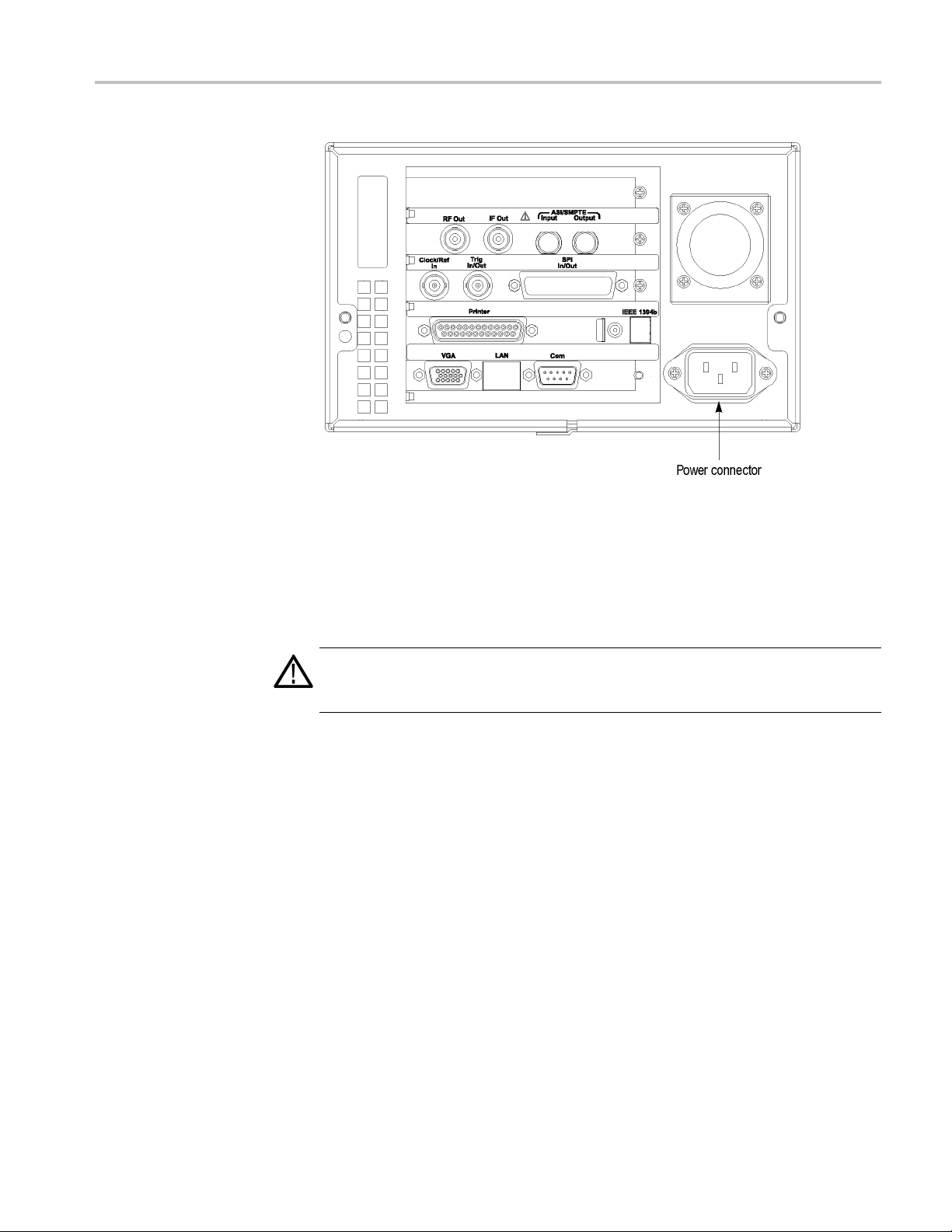
Figure 1-1: Rear-panel power connector
Getting Started
Power On. Press the On/Standby switch to power on the instrument. (See
Figure 1panel is operating. To verify that the fan is operating, place your hand behind the
right side of the instrument. You should be able to feel the fan’s air flow.
CAUTION. Do not operate the instrument if the cooling fan does not o perate when
you turn on the instrument. Ser ious damage to your instrument can occur from
overheating if the cooling fan is not operating.
2.) After you power on the instrument, verify that the fan on the rear
RTX130B QAM and VSB RF Signal Generator 1–7

Getting Started
Figure 1-2: Front-panel On/Standby switch
Repacking for Shipment
When you ship this instrument, use the original packaging material if possible. If
the original packaging is unfit for use or is not available, repackage the instrument
using the following procedure:
1–8 RTX130B QAM and VSB RF Signal Generator

Getting Started
1. Obtain a corrug
least six inches greater than the instrument dimensions and having a carton
test strength of at least 125 kg (275 pounds).
2. If the instrument is being shipped to a Tektronix Service Center for repair or
calibration, attach a tag to the instrument showing the following information:
The owner of the instrument (with address).
Thenameofap
information is needed.
The complet
A description of the service required.
3. Wrap the instrument with polyethylene sheeting or equivalent to protect the
outside finish and prevent entry of packing materials into the instrument.
4. Cushion the instrument on all sides by tightly packing dunnage or urethane
foam between the carton and the instrument, allowing for three inches
(7.62 cm)
5. Seal the carton with shipping tape or with an industrial stapler.
6. Mark the address of the Tektronix Service Center and your return address on
the carton in one or more prominent locations.
ated cardboard shipping carton having inside dimensions at
erson at your firm who may be contacted if additional
e instrument type and serial number.
of padding on each side (including top and bottom).
Functional Check Procedure
Perform the following procedure if you are operating the instrument for the first
time (to
the instrument is not working properly:
NOTE. Before you perform this procedure, install the RTX130B using the
instructions listed in Installation. (See page 1-5, Installation.)
1. Connect the RTX130B to a power source, and then turn on the instrument
using the On/Standby switch.
2. Press the front-panel Menu button to display the File menu command list.
3. Press the up (▲) or down (▼) arrow button to select Open from the list,
andthenpresstheEnter button to open the Select File dialog box. (See
Figure 1-3.)
verify that the instrument shipped without damage) or you suspect that
RTX130B QAM and VSB RF Signal Generator 1–9

Getting Started
Figure 1-3: Select File dialog box
4. Press the up (▲)ordown(▼) arrow button to select the test64.TRP file,
and then press the Enter button. The hierarchy view of the transport stream
file will b
e displayed on the screen.
NOTE. You can select the test40.TRP file in step 4 of this procedure if you need
to decrease the bit rate of the transport stream due to performance restrictions
in your decoder.
5. Connect the interface cable provided with the instrument between the SPI
In/Out connector on the RTX130B rear panel and the SPI In connector on an
MPEG decoder. (See Figure 1-4.)
6. Connect the decoder to a picture monitor.
7. Press the RTX130B Play/Pause button to start the transport stream output.
When transport stream output is started, the Play Status indicator appears
on the screen.
8. Check that the picture from the transport stream is displayed correctly on the
picture monitor.
1–10 RTX130B QAM and VSB RF Signal Generator

Getting Started
Windows Operations
Operation o n the
Play/Record Screen
Displaying the Windows
Screen (Desktop)
Figure 1-4: Equipment connection for the functional check
All of th
on the Windows XP operating s ystem. Therefore, if you connect the keyboard and
mouse provided with the instrument to the front-panel USB connectors, you can
operate the RTX130B system with the same environment as a Windows PC.
When you have connected a keyboard and mouse to the instrument, you can use
them to make menu selections and parameter settings in the Play/Record screen.
These operations behave in the same manner as the other Windows applications.
To display the Windows screen (Desktop), select Minimize or Exit from the
File menu in the Play screen or Record screen. When you click Minimize, the
RTX130B application window minimizes and the Windows XP desktop appears.
When you click Exit, the RTX130B application exits and the Windows XP
desktop appears.
e functions of the RTX130B are performed as an application (RTX130B)
RTX130B QAM and VSB RF Signal Generator 1–11

Getting Started
File Operation
System Settings
There are no men
application. Perform file operations such as copy, delete, or upload/download
on Windows. Refer to Windows XP Online Help or other documentation about
file operations.
The RTX130B application is placed in the C:\ProgramFiles\Tektronix\Mpeg
Player folder. The sample transport stream filesareplacedontheD:drive
(Volume D).
This manual describes only the settings for connecting to a n Ethernet network.
Refer to Windows XP Online Help or other documentation for information about
other system settings.
ucommandstomanagefile operations in the RTX130B
1–12 RTX130B QAM and VSB RF Signal Generator

Operating Basics


Operating Basics
Functional Overview
Front Panel Controls
This section explains the basics of operating the RTX130B. It gives a functional
overview and takes you through the basic menu operations.
This subsection contains descriptions of the front-panel controls and the rear-panel
connectors.
Figure 2-1: RTX130B front panel
On/Standby Switch. Powers on or off the instrument.
CAUTION. If you power off the instrument using the On/Standby switch, the
current instrument settings are not saved (this operation corresponds to an
emergency shutdown in Windows XP). To prevent data loss, use the Shutdown
command from the File menu to power off the instrument.
RTX130B QAM and VSB RF Signal Generator 2–1

Operating Basics
Stop Button. Th
If this button is pressed while a s tream data is being output, the data output
stops.
If this button is pressed while the pretrigger portion is filled and the instrument
waits for a tr
recorded data is stored in a file.
Play/Pause Button. This button performs the following functions:
If this button is pressed, the data output starts.
If this button is pressed while the Record screen is displayed, it switches to
the Play screen.
If this button is pressed while a s tream data is being output, the data output
pauses. Press the button again to star t the stream output.
When an M-TMCC transport stream is selected, RTX130B outputs the stream
from the start packet in the super frame to the maximum number of packets that
can be looped as an integral multiple of the number of super frames. When an
ISDB-T transport stream is selected, RTX130B outputs the stream from the start
packet in the OFDM (Orthogonal Frequency Division Multiplexing) frame to the
maximum
frames. If any of the transport streams within the ISDB-T transport stream have
different modulation parameters, select Non TS from the Packet Size command in
the Play menu. (See page 3-4, Play Menu.)
is button performs the following functions:
igger event or the posttrigger portion is being recorded, the
number of packets that can be looped as 2 X N of the number of OFDM
The status indicator light in the button illuminates when stream data is being
output. The light blinks when the stream output pauses.
Record Button. This button performs the following functions:
Press this button to record the stream data that is being applied.
If this button is pressed while the Play screen is displayed, it switches to
the Record screen.
Press this button to start the RF output of the modulated signal when a
broadcast transport stream is applied to the ASI In connector.
The status indicator light in the button blinks when a sync word is being detected,
or when the pretrigger portion of the stream data has been recorded.
Access Indicator. This indicator illuminates when the hard disk drive is
HDD
in operation.
Menu Button. Use this button to toggle the display of the menu command list
on or off.
2–2 RTX130B QAM and VSB RF Signal Generator

Operating Basics
Rear Panel Connectors
Arrow Buttons.
example, you can use these buttons to move the Icon cursor or to move among the
menu selections.
Enter Button. Use this button to execute the selected menu command or enable
all setting changes in a dialog box.
Cancel/Close Button. Use this button to cancel the selected operation. When any
menu command list is displayed, it c loses the command list temporarily.
Tab Button. Use this button to move through a dialog box.
Num Pad/Select Button. Use this button to enable or disable any setting changes
in a dialo
values for a text box.
USB Connectors. Use the USB2.0 connectors to connect the keyboard and mouse
provided with the instrument for Windows operations. You can also connect
other USB devices.
g box. It is also used to open the keypad, where you can enter numeric
Use the arrow buttons to maneuver on the LCD display. For
Figure 2-2: RTX130B rear panel
RF Out. Use this BNC connector to output an RF signal.
RTX130B QAM and VSB RF Signal Generator 2–3

Operating Basics
NOTE. The RF sig
is being output or applied.
ASI In. Use thi
signal. When you want to output an RF signal using an external broadcast
transport stream, a pply the transport stream to the connector.
ASI Out. Use this BNC connector to output an ASI (Asynchronous Serial
Interface) signal.
Clock/Ref In. Use this BNC connector to input an external reference signal or
clock signal to the RTX130B. Refer to the specifications for detailed information
about the signal specification. (See page A-1, Specifications.)
NOTE. Use a continuous signal for an external reference or clock signal.
Trig In/Out. Use this BNC connector to input an external trigger event for stream
recording or output a 27 MHz reference clock signal or an ISDB-T frame pulse
signal. You can change the configuration from the Play menu. (See page 3-4,
Play Menu.) Refer to the specifications for detailed information about the signal
specification. (See page A-1, Specifications.)
nal output is only available when a broadcast transport stream
s BNC connector to input an ASI (Asynchronous Serial Interface)
SPI In/Out. Use this 25-pin D-sub connector to input and output an SPI
(Synchronous Parallel Interface) signal.
Printer. Use this 25-pin D-sub connector to connect a printer. This interface
supports the IEEE 1284 parallel port standard.
IEEE1394b. Use this connector to connect an IEEE 1394b d
external hard disk drive.
VGA. Use this 9-pin D-sub connector to display the instrument screen to an
external monitor.
The VGA output is automatically enabled only when you power on the instrument
with an external monitor connected. If you want to enable the VGA output after
powering on the instrument, perform the following steps:
1. Minimize the Play screen to display the Windows XP desktop.
2. Click the Intel(R) Extreme Graphics 2M icon (see below) at the right side
of the taskbar.
3. Select Graphic Options > Output To > Intel(R) Dual Display Clone >
Monitor+Notebook from the displayed menu.
evice such as an
2–4 RTX130B QAM and VSB RF Signal Generator

Operating Basics
Display Elements
LAN(10/100/10
local Ethernet network.
Com. This 9-pin D-sub connector provides a serial interface for instrument
control.
Power Connec
supplied power cord.
There are two types of display screens to operate the RTX130B: the Play screen
and the Rec
Play screen is used to output the selected stream. When you power on the
instrumen
powering down.
Record sc
button or select the Record command from the File menu while the Play
screen is displayed, the screen switches to the Record screen.
This subsection explains the display elements that make up the Play and Record
screens.
The following figure shows the location of display elements of the Play screen.
The display elements of the Record screen are the same as that of the Play screen.
00 Base-T). Use this connector to connect the RTX130B to your
tor. Use this connector to apply power to the instrument using the
ord screen.
t, this screen will display the last screen that was showing before
reen is used to record the input stream. When you press the REC
RTX130B QAM and VSB RF Signal Generator 2–5

Operating Basics
Figure 2-3: Elemen
2–6 RTX130B QAM and VSB RF Signal Generator
ts of the Play s creen
Menu Bar. The Menu bar displays the names of the menus that can be used in
the Play or Record screen. Press the Menu button to enable or disable the menus.
(See page 3-2, Using the Menus.)
Toolbar. The toolbar provides shortcut buttons for many of the most often used
menu commands. Click a toolbar button to select the corresponding command.
You can toggle the toolbar display on and off using Toolbar command in the View
menu. (Seepage3-44,Toolbar Buttons.)

Operating Basics
Hierarchy Disp
the stream. The hierarchy text contains a description of the associated icon. (See
page 3-45, Hierarchy Display.)
Icon Cursor. The icon cursor appears as a red box around an icon in the hierarchy
to indicate the currently selected icon.
Use the up (▲)ordown(▼) arrow button to move the icon cursor between icons.
When the icon cursor is at the top or bottom of the hierarchy display, the hierarchy
scrolls to s
Play/Record Status Indicator. The play status indicator is displayed while the
selected stream is being output. (See Figure 2-4.) It shows the output status of
the selected stream: the progress of the stream output, the output source, the
operational status, and the elapsed time.
The record status indicator is displayed while the input stream is being recorded.
It shows the record status of the input stream: the progress of the stream record,
the reco
lay. Each icon in the hierarchy display represents an element of
how additional elements of the stream when applicable.
rd target, and the elapsed time.
Figure 2-4: Play s tatus indicator
The play/record status indicator shows the following information:
1. Position Indicator. In the Play screen, this indicator shows the progress
of the stream output using the duration gauge. In the Record screen, this
indicator shows the progress of the stream record using the duration g auge.
The duration gauge is updated every 1 second. If you output a stream with a
repetition rate of around 3 seconds, the gauge might not be displayed correctly.
2. Output Source/Record Target. In the Play screen, this indicator shows the
output source used to output the selected stream. In the Record screen, this
indicator shows the record target used to record the input stream.
One of the following icons is displayed according to the selected output
source or record target:
RTX130B QAM and VSB RF Signal Generator 2–7

Operating Basics
This icon shows
This icon shows
that the hard disk is the output source or record target.
that the RAM is the output source or record target.
3. Operation Status. Shows the current operation status of the instrument.
In the Play screen, the following icons are used:
This icon shows that the selected stream is being output.
This icon shows that the stream output is stopped.
This icon shows that the selected stream is being read from the hard disk
to the RAM.
This icon shows that the stream is continuously output using the loop method.
This icon indicates that the stream parameters are updated.
This icon shows that the PCR accuracy is enabled.
This icon (only in IP mode) shows that the Advanced Protocol Settings is
enabled and applied to the stream.
This icon (only in IP mode) shows that the Stream Replication Settings is
enabled and applied to the stream.
This icon (only in IP mode) shows that the errors are inserted in the stream.
This icon (only in IP mode) shows that the parametric settings are enabled and
applied to the stream.
In the Record screen, the following icons are used:
This icon shows that the captured stream is being recor
This icon shows that the stream record is stopped.
This icon shows that the RTX130B is waiting for a trigger event.
ded.
2–8 RTX130B QAM and VSB RF Signal Generator

Operating Basics
Figure 2-5: Status bar
This icon shows
This icon shows
This icon shows that the captured stream is being saved from the RAM to
the hard disk.
that a trigger event is occuring.
that the captured stream is being processed on the hard disk.
4. Elapsed Time. In the Play screen, this box displays the elapsed time of the
current stream data output.
In the Record screen, this box displays the elapsed time since the input stream
was recorded.
Status Bar. The status bar contains several indicators that display general
information about the transport stream output or record status. (See Figure 2-5.)
Figure 2-6: Status bar in IP mode
RTX130B QAM and VSB RF Signal Generator 2–9

Operating Basics
The Status bar s
1. Standard. In the P lay screen, this indicator shows the standard used to display
the selected s
or Non TS). In the Record screen, this indicator shows the standard used
to display the input stream.
2. Packet Size. In the Play screen, this indicator displays the packet size in
bytes (188, 204, 208, Non TS, or Partial TS (Option 05 only)) of the stream
output. In the Record screen, this indicator displays the packet size in bytes of
the input stream.
3. Clock Source. This indicator displays the source of the reference clock
(internal or external) used for the stream output.
4. Bit Rate. In the Play screen, this indicator displays the bit-rate (in Mbps) of
the stream output. In the Record screen, this indicator displays the bit-rate (in
Mbps) of the input stream.
5. TTS Mode. In the Play screen when IP interface option is selected with the
TTS mode enabled, this indicator displays that the TTS mode is enabled for
the play
6. IP Bit Rate. In the Play screen when the IP interface option is selected, this
indicat
screen is disabled for the IP interface option.
hows the following information:
tream (MPEG-2, ARIB, DVB, ATSC, S-TMCC, M-TMCC,
out. The Record screen is disabled for the IP interface option.
or displays the bit rate (Mbps) of the IP stream output. The Record
7. Free RA
space that can be used t o output the selected stream. In the Record screen,
this indicator shows the free RAM space that can be used to record the input
stream.
8. Output Source/Record Target. In the Play screen, this indicator shows the
source used to output the selected stream. In the Record screen, this indicator
shows the target used to record the input stream.
This indicator is the same as the output source/record target indicator of the
Play/Record Status indicator.
tatus Display. Displa ys a paramete r and an icon related to the RF output.
RF S
ure 2-7: RF Status Display
Fig
Mspace. In the Play screen, this indicator shows the free RAM
2–10 RTX130B QAM and VSB RF Signal Generator

Operating Basics
1. This indicator
RF output. This value can be set using the RF Parameter command in the
ISDB-T/ASI menu.
2. This icon appears while outputting an RF signal.
Remote Connection Status Icons. The remote connection status icons appear
when a TCP/IP connection for remote control is established. The right icon shows
the status of the TCP/IP connection (this icon is always displayed when the
TCP/IP conn
front-panel buttons and mouse input.
There are t
To reset the lock status, send the :SYSTem:KLOCk:STATe OFF command or
press the Cancel/Close button on the front panel (if a keyboard is connected,
presstheEsckey).
wo display states:
display the center frequency (UHF channel number) for the
ection is established), and the left icon shows the lock status of the
This shows that the TCP/IP connection for remote control is established.
This shows that the TCP/IP connection for remote control is established
and the front-panel buttons and mouse input are locked by the
:SYSTem:KLOCk:STATe ON command.
Basic Menu Operation
When the TCP/IP connection is closed, the remote status icons disappear.
This section describes the basics of using the RTX130B menu and the methods for
entering numeric input in the various dialog boxes.
The menus are displayed in the menu bar at the top of the Play or Record screen.
You can operate these menus using the front-panel Menu, Enter, Cancel/Close,
Tab, Num Pad/Select, and the arrow buttons. (See Figure 2-8.)
RTX130B QAM and VSB RF Signal Generator 2–11

Operating Basics
Figure 2-8: Front panel showing the menu controls
Accessing Menu Commands. To access any menu command, press the Menu
button. When you press the Menu button, the File menu command list opens.
Use the up (▲)ordown(▼) arrow button to move through the command list.
Press the Enter button to execute the selected command.
Use the left (◄)orright(►) arrow button to select the desired menu. Press the
Cancel/Close button to close the command list temporarily.
Press the Menu button again to close the menu command list.
NOTE. When you press the left arrow button while the File menu is displayed
or when
the Windows Control menu appears.
you press the right arrow button while the Utility menu is displayed,
2–12 RTX130B QAM and VSB RF Signal Generator

Operating Basics
Numeric Input
Display States
following three d isplay states. (See Figure 2-9.)
Acommandfoll
displayed after you press the Enter button or the right (►) arrow button.
A command fol
box will open after you press the Enter button.
A command nam
Figure 2-9: Display status of the menu commands
You can enter numeric values in the d isplayed dialog box by using the keypad
or by using the arrow buttons.
of the Menu Commands. Themenucommandscanhavethe
owed by “►” indicates that a corresponding submenu will be
lowed by an ellipsis (...) indicates that a corresponding dialog
e by itself will be executed after you press the Enter button.
RTX130B QAM and VSB RF Signal Generator 2–13

Operating Basics
Numeric Input U
numeric values using the keypad. (See Figure 2-10.)
1. Open a dialog b
2. Press the Ta b button repeatedly to select (highlight) the numeric parameter
that you want
3. Press the Num Pad/Select button to open the keypad. (See Figure 2-10.)
Figure 2-10: Keypad
4. Press the Tab button or the arrow buttons to move to the number you want
to input (when the keypad first opens, the dotted line box is located on the
ENT key).
sing the Keypad. Perform the following procedure to input
ox in which you want to change a parameter.
to change in the open dialog box.
5. Press the Num Pad/Select button. This displays the selected number in the
numeric
6. Repeat steps 4 and 5 to input the desired parameter value.
7. Press the Enter button (or select the ENT key and then press the Num
Pad/Select button). This saves the new value in the numeric input box and
closes
input box.
the keypad.
2–14 RTX130B QAM and VSB RF Signal Generator

Operating Basics
About the D
Numeric Input U
change a value by using the arrow buttons:
1. Open the dialo
2. Press the Tab button repeatedly to select the numeric parameter that you
want to chang
3. Press the left (◄) arrow button to begin editing the parameter. This highlights
the last digi
4. Press the left (◄)orright(►) arrow button to move the highlighted cursor to
the value yo
5. Press the up (▲)ordown(▼) arrow button to increase or decrease the value.
6. Repeat steps 4 and 5 to enter all of the desired values. To add a digit, press the
left (◄) arrow button.
7. Press the Enter button to save the changed numeric values.
ata Output Source
When you output the selected stream data, you can select either the hard disk or
the RAM as the output source. This subsection describes the operation of the
RTX130B w
sing the Arrow buttons. Perform the following procedure to
g box in which you want to change a p arameter.
e in the open dialog box.
t.
u want to change.
hen each output source is selected.
RAM
When you select the RAM as the output source, the RTX130B performs the
following:
When the data output rate is less than or equal to 120 Mbps, the RTX130B
outputs the first stream data while transferring the data from the hard disk
to the R
looping methods.
When t
outputs a stream data from the RAM u sing looping methods after the data is
completely transferred from the hard disk to the R AM.
If you select the RAM as the output source, you cannot output the data over the
RAM free space (maximum 256 MB). This RAM free space is displayed on the
status bar. (See page 2-9, Status Bar.)
AM and then continuously outputs the data from the RAM using
he data output rate is more than 120 Mbps, the RTX130B continuously
RTX130B QAM and VSB RF Signal Generator 2–15

Operating Basics
Hard Disk
If you select th
outputs the selected stream data from the hard disk regardless of the data output
rate. When the reading speed of the hard disk cannot overtake the data output rate,
the message “Error: Output Buffer Empty” appears.
Use the Source command in the Play menu to select the output source. (See
page 3-4, Play Menu.)
You can see the currently selected output source in the status bar. (See page 2-9,
Status Bar.)
e hard disk (Disk) as the output source, the RTX130B always
2–16 RTX130B QAM and VSB RF Signal Generator

Tutorials
Tutorials
This section provides the following tutorials to familiarize you with the basic
functions of the RTX130B:
Outputting a transport stream
Recording a transport stream
Outputting an RF modulated broadcast transport stream
NOTE. These tutorials do not cover all the features and functions of the RTX130B.
The tutorials are intended to introduce you to the operations required to execute
the basic instrument functions.
Refer to the Reference section for detailed descriptions of the menus and functions
used in these procedures.
Before you perform these tutorials, make sure that the RTX130B is properly
installed. (See page 1-5, Installation.)
Required Equipment
The following table lists the equipment required to perform the tutorials. Accuracy
of alternate equipment should equal or exceed that of the example instruments
and accessories.
Table 2-1: Tutorial recommended test equipment and accessories
Item Qty. Require
MPEG tes
ISDB-T receiver
75 Ω BNC cable
Outpu
t system
tting a Transport Stream
1 Real-time transport stream analyzer
1
1 Length
The hard disk drive of the RTX130B is shipped with files containing
factory-supplied samples of transport streams. This tutorial opens one of these
e files and outputs the transport stream.
sampl
Perform the following steps to select and output a stored transport stream:
1. Press the front-panel Play/Pause button to display the Play screen.
ment
: 42 inches
Example
ix MTS400 Series MPEG Test
Tektr on
Systems or equivalent
Panasonic VP-8480A ISDB-T Analyzer
nix part number 012-0074-00
Tektr o
2. Press the Menu button to open the File menu.
RTX130B QAM and VSB RF Signal Generator 2–17

Tutorials
3. Press the up (▲)
andthenpresstheEnter button to open the Select File dialog box. (See
Figure 2-11.)
Figure 2-11: Select File dialog box
or down (▼) arrow button to select Open from the menu,
4. Press the up (▲)ordown(▼) arrow button to select the test64.TRP file, and
then press the Enter button. This displays the hierarchy view of the transport
stream file. (See Figure 2-12.)
Figure 2-12: Hierarchy view of the transport stream file
2–18 RTX130B QAM and VSB RF Signal Generator

Tutorials
5. Connect the 75 Ω
RTX130B rear panel to the ASI In connector of the MPEG test system.
6. Press the RTX1
When transport stream output is starte d, the play status indicator appears and
the indicato
Figure 2-13: Play status indicator
7. Set up the MPEG test system to monitor the transport stream output from the
RTX130B. (See Figure 2-14.)
8. Press the Stop button on the RTX130B to stop the transport stream output.
Observe that the Play Status indicator disappears.
r button illuminates. (See Figure 2-13.)
BNC cable between the ASI Out connector on the
30B Play/Pause button to start the transport stream output.
Figure 2-14: Transport stream display from an MPEG test system
Recording a Transport Stream
This tutorial captures a transport stream being applied into the ASI In connector
and records it on the hard disk as a fi le.
RTX130B QAM and VSB RF Signal Generator 2–19

Tutorials
NOTE. The IP int
the Record option is disabled for IP.
Perform the fo
hard disk as a file:
1. Press the fro
Since no signal is being applied at this time, the No Signal message appears at
the top of th
Figure 2-15: No Signal message
2. Connect the 75 Ω BNC cable between the ASI/SMPTE Input connector
on the RTX130B rear panel and the ASI OUT connectoroftheMPEGtest
system.
3. Output a transport stream from the MPEG test system.
erface mode does not support the Record functionality and hence
llowing steps to capture a transport stream and record it on the
nt-panel Record button to display the Record screen.
e screen. (See Figure 2-15.)
When transport stream output is started, the hierarchy view of the transport
stream is displayed o n the Record screen of the RTX130B.
4. Press the RTX130B Record button.
When you press the button, the record status indicator appears and the
indicator button illuminates. (See Figure 2-16.)
Figure 2-16: Record status indicator
After the transport stream record is completed, the record status indicator
disappears, and the transport stream is saved automatically with a file name that
shows the current date (yy:mm:dd).
Outputting an RF modulated broadcast transport stream
The hard disk drive of the RTX130B is shipped with files containing
factory-supplied samples of broadcast transport streams. This tutorial converts
a broadcast transport stream into an RF signal and outputs it from the RF Out
connector.
2–20 RTX130B QAM and VSB RF Signal Generator

Tutorials
1. Press the front
2. Select the Open command from the File menu to open the Select File dialog
box.
3. Press the up (▲)ordown(▼) arrow button to select the 525 folder, and press
the Enter but
4. Press the up (▲)ordown(▼) arrow button to select Flower.rmx,andpress
the Enter but
stream file.
5. Select QAM/
6. Select QAM/VSB > Modulation to open the Modulation dialog box.
-panel Play/Pause button to display the Play screen.
ton. This displays the content of the 525 folder.
ton. This displays the hierarchy view of the selected transport
VSB > RF Output > On to enable the RF output.
Set the R
standard.
7. Connec
rear panel and the RF INPUT connector on the RF receiver.
8. Press t
9. Use the RF receiver to check that the RF modulated transport stream is output
from t
RTX130B QAM and VSB RF Signal Generator 2–21
F modulation parameters in the dialog box to meet your modulation
tthe75Ω BNC cable between the RF Out connector on the RTX130B
he RTX130B Play/Pause button to start the transport stream output.
he RF Out connector.

Tutorials
2–22 RTX130B QAM and VSB RF Signal Generator

Reference


Reference
The Reference section gives you information on how to use the menus, a dd
jitters to PCRS, connect to a network, and hierarchy display. The command
syntax, remo
specifications are all listed in this section.
te commands, default settings, error messages, and network interface
RTX130B QAM and VSB RF Signal Generator 3–1

Using the Menus
Using the Menus
This section describes the function of each selection available in the menus. This
section is divided into the following subsections:
Menus in the Play Screen describes all of the menu commands and their
features available in the Play screen.
Menus in the Record Screen describes all of the menu commands and their
features available in the Record screen.
Toolbar Buttons describes the toolbar buttons and their functions.
Refer to Basic Menu Operation for information about how to operate the menus.
(See page 2-11.)
Menus in the
Play Screen
File Menu
This subsection describes the menus available in the Play screen.
The File menu in the Play screen contains commands for selecting a stream file
and for loading and saving a preset file. This menu also contains commands to
exit the RTX130B application and to shutdown the instrument. (See Table 3-1.)
Table 3-1: File menu commands (Play screen)
Command Description
Open Opens a stream file. When a file is selected, the RTX130B checks the
packet size of the file. For a transport stream file, the data is output
in packets. If an incomplete packet is included at the start or end of
the file, that portion of the file is not output. The available minimum
data size is 104 KB.
When you select this command, the Select File dialog box appears.
(See page 3-3, Select File D ialog Box.)
Load Preset
Save Preset Saves the current instrument settings as a preset file. (See page 3-67,
RECORD Switches to the Record screen.
Scheduler Starts the Scheduler application when the Option SC is installed.
Minimize Minimizes the RTX130B application window.
Loads the specified preset file (*.set). When a preset file is loaded, the
current instrument settings are replaced by the settings in the preset
file. (See page 3-67, Preset File.)
Preset File.)
3–2 RTX130B QAM and VSB RF Signal Generator

Using the Menus
Table 3-1: File menu commands (Play screen) (cont.)
Command Description
Exit
Shutdown Quits the RTX130B application and shuts down the RTX130B.
Quits the RTX130B application. The RTX130B application settings
are saved.
Select File Dialog Box. When you select the Open command from the File menu,
the Select
File dialog box appears. (See Figure 3-1.)
Figure 3-1: Select File dialog box
You can perform the following functions in Select File dialog box:
Press the arrow buttons to select the desired file, and press the Enter button to
load the selected file.
Select Up One Level to move from the current directory to the directory
one level higher.
Click the “...” button at the upper right of the dialog box to select a file that
is not listed.
RTX130B QAM and VSB RF Signal Generator 3–3

Using the Menus
View Menu
Play Menu
The View menu co
ntains commands that control the display of the Toolbar and
Status bar. (See Table 3-2.)
Table 3-2: View menu commands
Command Description
Toolbar
Status Bar Toggles the display of the Status bar on and off in the Play screen.
The Play me
nu contains commands for defining output parameters such as packet
Toggles the display of the Toolbar on and off in the Play screen. A
check mark pr
selected for display.
A check mark precedes the command in the menu when the Status
bar is selec
ecedes the command in the menu when the Toolbar is
ted for display.
size, output clock rate, or output source. (See Table 3-3.)
Table3-3: Playmenucommands
Command Description
Interface Sets the interface to transmit and receive Ethernet packets. You can
ither IP or QAM/VSB.
select e
Packet S
Clock Opens the Clock dialog box where you can set the clock rate of the
Update
Sync Sets the format of the PSYNC signal output from the SPI In/Out
ize
Sets the
size to 188 (188 + 0), 204 (188 + 16), 208 (188 + 20) bytes, or Non TS.
These packet sizes can only be set for an M PEG-2 transport stream.
For an Sto 204. For a Non TS stream, the packet size is fixed to Non TS.
The packet size is fixed to 188 when you set RF Output to On in the
QAM/VS
When you select Non TS, the RTX130B deals with stream data in a
byte unit (not a packet unit) and outputs all of the data in a file. If a
transp
Non TS.
stream output. (See page 3-5, Clock Dialog Box.)
Sets whether to update parameters in the stream when looped. You
can se
You can select which parameters in the stream are updated using the
Others dialog box. (See page 3-13, Others Dialog Box.)
conne
a single pulse signal is output at the start of each packet. For SF, a
single pulse is output at the start of the SF appearing every 204 X 48
X8by
where you can enable the PSYNC and DVALID signals. You cannot
select Non TS when you set RF Output to On in the QAM/VSB menu.
(See
packet size (in bytes) for the stream. You can set the packet
TMCC or M-TMCC transport stream, the packet size is fixed
B menu.
ort stream contains any error, you can output it by selecting
lect On or Off. You cannot select On for a Non TS stream.
ctor. You can select TS Packet, SF, or Non TS. For TS Packet,
tes. For Non TS, the Set Non-TS Sync dialog box appears,
page 3-9, Set Non-TS Sync Dialog Box.)
3–4 RTX130B QAM and VSB RF Signal Generator

Using the Menus
Table 3-3: Play menu commands (cont.)
Command Description
PCR Initial Value Opens the PCR Initial Value dialog box where you can set
the initial value of the program_clock_reference_base and
program_clock_reference_extension parameters when the transport
stream is output. (See page 3-10, PCR Initial Value Dialog Box.)
Source Selects the source for stream output. You can select RAM or Disk.
(See page 2-15, About the Data Output Source.)
Loop
Start/Stop Opens the Start/Stop Position dialog box where you can set the start
Auto Play
Timer Play
Other Opens the Other dialog box where you can set the standard used to
Sets whether or not the stream is output using the looping method.
You can select On or Off. If you select On, the selected stream is
continuously output. If you select Off, the selected stream is output
once.
and stop positions of the stream, and initial start position of the stream
for loop output. (See page 3-10, Start/Stop Position Dialog Box .)
Sets whether or not the transport s tream is automatically output using
the last power-off settings when you turn on the RTX130B. You can
select On or Off.
Opens the Timer Play/Record dialog box where you can set the date
and time used to output a stream automatically. (See page 3-12,
Timer Play/Record Dialog Box.)
display the selected stream and display radix for the text information.
(See page 3-13, Others Dialog Box.)
Clock Dialog Box. When you select the Clock command from the Play menu, the
Clock dialog box appears. (See Figure 3-2.)
Figure 3-2: Clock dialog box for Option Interface
RTX130B QAM and VSB RF Signal Generator 3–5

Using the Menus
Figure 3-3: Clock dialog box for IP Interface
Clock Source: Sets the clock that will be used as the re ference for the stream
output. You can select from the following settings:
Internal uses the internal clock of the RTX130B as the clock reference.
Ext Ref allows you to input a signal on the Clock/Ref In connector for
use as the clock reference. When you select the button to the right of the
ExtRef box, the following External Reference dialog box appears.
10 MHz: Selects a 10 MHz signal on the Clock/Ref In connector.
27 MHz: Selects a 27 MHz signal on the Clock/Ref In connector.
ISDB-T IFFT Clock: Selects a signal corresponding to the IFFT
sample clock rate (8.126984 MHz) on the Clock/Ref In connector.
Ext P Clk (external parallel clock) allows you to input a clock signal on
the Clock/Ref In connector for use as the parallel clock.
Ext S Clk (external serial c lock) allows you to input a clock signal on the
Clock/Ref In connector for use as the serial clock.
3–6 RTX130B QAM and VSB RF Signal Generator

Using the Menus
Data Rate: Sets
the clock rate using the following methods (the first method provides greater
clock-rate precision):
Enter values into the numerator a nd denominator text boxes. (See
Figure 3-2.) TheRTX130B will calculate the clock rate based on the ratio
of the numerator and denominator values.
Enter a value into the clock rate text box. The RTX130B will calculate the
numerator and denominator values based on the clock rate.
Enter a value into the clock rate text box. The RTX130B will then calculate
the numerator and denominator text boxes based on the clock rate.
NOTE. The IP data rate will be automatically calculated based on the available
TS data rate. IP Data Rate is calculated as follows:
IP Data Rate = (TS Data Rate × IP Packet Size) ⁄ Payload Size
When you use the Ext P Clk or Ext S Clk mode, set the clock rate to the same
value as the input clock signal. Also, when you use the Ext S Clk mode, you
cannot set the value more than 32 Mbps.
When you set the RF Output command in the QAM/VSB menu to On, this
value is fixed to the bit rate that is calculated from the symbol rate setting.
the clock rate for the transport stream output. You can enter
IP Data Rate: Sets the clock rate for the IP packet. (See Figure 3-3.) In the
IP mode, a change in the IP data rate will impact the TS data rate and a change
in the T
according to the selected protocol.
NOTE. The TS data rate will be automatically calculated based on the available
IP data rate and consequently influence the PCR/PTS/DTS update cycles. TS
Data Rate is calculated as follows:
TS Data Rate = (IP Data Rate × Payload Size) ⁄ IP Packet Size
When IP data rate is more than 80 Mbps, a Recommended Settings dialog box
is displayed asking you to do the settings for optimal performance.
S data rate will impact the IP data rate. The packet length changes
RTX130B QAM and VSB RF Signal Generator 3–7

Using the Menus
FixedESRate: Sets whether the elementary stream rate is fixed or not.
When it is selected, the elementary stream rate becomes constant regardless
of the clock rate setting. If you fix the elementary stream rate, you cannot
set the output clock rate (Data Rate) to more than the data rate set when the
stream file was downloaded.
When Fixed ES Rate is selected, PCR/PTS/DTS Update Method in the Select
Update Item dialog box is set to Hardware automatically. (See page 3-2,
Using t
he Menus.)
If you enable the Fixed ES Rate check box when the RF Output command
in the Q
AM/VSB menu is set to On, you can output the various RF signals
without changing the elementary stream rate.
llowing table shows the relationship between the Fixed ES Rate setting
The fo
and PCR jitter occurrence when outputting a signal.
Table 3-4: Relationship between Fixed ES Rate Setting and PCR Jitter
Fixed ES Rate: checked Fixed ES Rate: not checked
Update: Hardware
Update: Software PCR jitter meets the standard,
Update: Off PCR Jitter occurs PCR, PTS/DTS discontinuity
PCR jitter meets the standard PCR jitter meets the standard
ided that the original file
prov
does not contain any PCR jitter
occurs on loop points
Default Rate: Displays the default clock rate and packet size and then
anges the values. When you select this button, the following Default Clock
ch
dialog box appears.
3–8 RTX130B QAM and VSB RF Signal Generator

Using the Menus
Default Data Rate: Overwrites the scanned bit rate value of the stream file.
Since the default clock rate is calculated based on the PCRs in the downloaded
stream file, the value can be different from the original clock rate. When the
elementary stream rate is fixed (refer to the Fixed ES Rate description), the
instrume
is different from the original clock rate, you need to set it to the appropriate
value. If you change the value, the clock rate value in the Data Rate dialog
box is also changed.
nt refers to the default clock rate. Therefore, if the default clock rat e
Packet Size: Changes the default packet size when the selected stream file
is downloaded. If you change the value, the Packet Size setting in the Play
menu will also change.
Set Non
in the Play menu, the Set Non-TS Sync dialog box appears. (See Figure 3-4.)
Figu
-TS Sync Dialog Box. When you select Non-TS from the Sync command
re 3-4: Set Non-TS Sync dialog box
RTX130B QAM and VSB RF Signal Generator 3–9

Using the Menus
Psync Enable: S
In/Out connector.
Interval: Ent
255 bytes. A value equal to or greater than the Width value can be entered in
the Interval field.
Dvalid Enable: Sets the status of the DVALID signal output from the SPI
In/Out connector.
Width: Enter the data width of the DVALID signal in the range of 16 to
255 bytes.
PCR Initial Value Dialog Box. When you select the PCR Initial Value command
from the Play menu, the PCR Initial Value dialog box appears. (See Figure 3-5.)
ets the status of the PSYNC signal output from the SPI
er the output period of the PSYNC signal in the range of 16 to
Figure 3-5: PCR Initial Value dialog box
Base Value: Sets the initial value for the program_clock_reference_base
value.
represents the number of bits for the program_clock_reference_base field.
Extens
extension value. You can enter a value from 0 to 299. The bracketed number
represents the number of bits for the program_clock_reference_extension
field.
Start/Stop Position Dialog Box. When you select the Start/Stop command from
the P
You can enter a value from 0 to 8589934591. The bracketed number
ion Value: Sets the initial value for the program_clock_reference_
lay menu, the Start/Stop dialog box appears. (See Figure 3-6.)
3–10 RTX130B QAM and VSB RF Signal Generator

Using the Menus
Figure 3-6
: Start/Stop Position dialog box
Start: Set
packets(thenumberofsuperframesforanM-TMCCfile, or the number of
bytes for a Non TS file). Based o n the format selected from the Format list
box, you can either enter the value or move the slider to set the position.
Stop: Sets the stop position of the stream by time (h:m:s) or the number of
packets(thenumberofsuperframesforanM-TMCCfile, or the number of
bytes for a Non TS file). Based o n the format selected from the Format list
box, you can either enter the value or move the slider to set the position.
Initial: Sets the initial start position of the stream for loop output. You can
set the value by time (h:m:s) or the number of packets (the number of super
frames
on the format selected from the Format list box, you can either enter the value
or move the slider to set the position.
Play: Shows the actual time or number of packets (the number of super
frames for an M-TMCC file, or the number of bytes for a Non TS file) that is
calculated by the values of the Start and Stop text boxes.
Format: Specifies the way to set the start, stop, and initial positions of the
stream. For a transport stream file, you can select Time or Packets. For an
M-TMCC file, you can select Time or SF (super frame). For a Non TS file,
you can select Time or Bytes.
s the start position of the stream by time (h:m:s) or the number of
for an M-TMCC file, or the number of bytes for a Non TS file). Based
For an ISDB-T file,thestartpacketisdefined as the first-appearing packet
including an OFDM frame start flag after the spe cified start position. The stop
cket is defined as the packet before the last-appearing packet including an
pa
OFDM frame start flag before the specified stop position. If the number of
OFDM frames between the start packet and stop packet is not an even number,
the packet in the last OFDM frame becomes the stop packet.
RTX130B QAM and VSB RF Signal Generator 3–11

Using the Menus
To set the start
directly in the text boxes. (See Figure 3-6.)
Using the slid
1. For the start and stop positions:
a. Press the Tab button repeatedly to select the slider.
b. Press the left (◄)orright(►) arrow button to move the slider to the place
c. Press the Ta b button repeatedly to select the Stop option button, and then
d. Repeat steps a and b to set the value for the Stop option.
e. Press the Enter button to enable the values.
2. For the initial start position for loop output:
a. Press the Ta
b. Press the T
c. Press the left (◄)orright(►) arrow button to move the slider to the place
, stop, and initial positions, either use the slider or enter the values
er:
you want to set the start position.
press the Num Pad/Select button. This moves the slider to the right end.
b button repeatedly to s elect the Initial check box, and then
press the Num Pad/Select button. A red arrow appears on the slider.
ab buttonrepeatedlytoselecttheredarrow.
you want to
set the initial start position.
d. Press the Enter button to enable the value.
Using the text boxes:
1. Press the Ta b button repeatedly to select the Start text box. If you set a time,
select one of the text boxes for setting the hour, minute, or second.
2. Press the Num Pad/Select button. The keypad appears.
3. Use the keypad to enter the value.
4. If you set a time, repeat step 1 through step 3 to set the hour, minute, and
second.
5. Use the same procedure given in step 1 through step 4 to set the value in
the Stop text box.
6. Press the Enter button to enable the values.
To rese
press the Tab button repeatedly to select the Reset button, and then press the
Num Pad/Select button.
Timer Play/Recor d Dialog Box. When you select the Timer Play command from
the Play menu, the Timer Play/Record dialog box appears. (See Figure 3-7.)
t all of the settings to the values when the dialog box was first displayed,
3–12 RTX130B QAM and VSB RF Signal Generator

Using the Menus
Figure 3-7: Timer Play/Record dialog box
Start at: Sets the date and time whe n the stream output or record starts. Press
the Tab button to select year, month, date, hour, minute, or second, and then
press the up (▲)ordown(▼) arrow button to set the value.
If a mouse is connected to the RTX130B, you can display a calendar for date
setting by clicking the ▼ arrow button at the right of the date display.
When you press the Enter button after setting the date and time, a dialog box
showing the current date and time, and set date and time is displayed. When
the date and time arrives, the dialog box closes and stream output or stream
record starts automatically.
If you want to cancel the operation, press the Enter, Cancel/Close,orNum
Pad/Select button. When the dialog box that prompts you to confirm the
operation is displayed, press the Num Pad/Select or Enter button to execute
the operation.
Others Dialog Box. When you select the Other command from the Play menu, the
Others dialog box appears. (See Figure 3-8.)
Figure 3-8: Others dialog box
Standard: Sets the standard used on the hierarchy-display screen. You can
select ARIB, ATSC, DVB, or MPEG-2. For a transport stream (ARIB, ATSC,
RTX130B QAM and VSB RF Signal Generator 3–13

Using the Menus
DVB, or MPEG-2)
For an S-TMCC, M-TMCC, or ISDB-T transport stream, you need to select
ARIB for proper display.
Numeric: Sets the base value used to describe the component information in
the hierarchy display. You can select Decimal, Hex, or Octal.
Ext Play Start: Sets whether or not to start stream output using a trigger
signal applied to the Trig In/Out connector. You can select Off, Rise, or Fall.
When you select Rise, the stream output is started at the rising edge of the
applied trigger signal. When you select Fall, the stream output is started at the
falling edge of the applied trigger signal.
SPI Output Enable: Sets whether the signal output from the SPI In/Out
connector is enabled or not. If the Source command in the Record menu is
set to STD
if you select the check box.
Ext Trigg
BNC dialog box appears.
, the signal output from the SPI In/Out connector is disabled even
er BNC: When you select this button, the following Ext Trigger
, the standard is set to the previous setting as a default.
BNC IN/OUT: Sets whether to use the rear-panel Trig In/Out connector as a
trigger signal input or a reference clock/ISDB-T frame clock signal output.
You can select Input or Output. For Input, the Trig In/Out connector can be
used to input an external trigger event. For Output, the Trig In/Out connector
can be used to output a 27 MHz reference clock or an ISDB-T frame pulse
signal. Use the Selection list box to select which signal is output from the
connector.
BNC OUT property: Selects the output signal from the Trig In/Out connector
when BNC IN/OUT is set to Output. You can select 27 MHz or ISDB-T
Frame Pulse. If you select 27 MHz, a 27 MHz reference clock signal is output
from the Trig In/Out connector. Use this option to check the clock frequency
accuracy. If you select ISDB-T Frame Pulse, an ISDB-T frame pulse signal is
output from the Trig In/Out connector.
3–14 RTX130B QAM and VSB RF Signal Generator

Using the Menus
ISDB-T Frame Pu
pulse of the ISDB-T frame in 1-parallel clock of the SPI output. You can
set the value from 0 to 15.
TDT/TOT or STT: When you select this button, the following TDT/TOT
dialog box appears. The name changes to the standard that is selected in the
Standard list box: TDT/TOT for ARIB or DVB, and STT for ATSC. Use
this dialog box to change the initial date and time of the TDT (Time and
Data Table), TOT (Time Offset Table), or STT (System Time Table) in the
selected s
The button is disabled when MPEG-2 is selected in the Standard list box.
tream.
lse Delay: Sets the amount of delay for the start packet
Original: Uses the original (default) value that is already definedinthe
selected stream.
OS (Windows XP) Time: Uses the clock/calendar of the operating system
(Windows XP) to set the initial value. When you select this option, the date
and time of all the TDTs, TOTs, or STTs in the selected stream are locked to
the clock/calendar of the operating system.
User Define: Uses a user-defined value to set the initial value. When you
select this option, the list boxes for setting the initial date and time of the TDT,
TOT, or STT are available.
ISDB/P-TS: When you select this button, the following ISDB/P-TS dialog
box appears.
RTX130B QAM and VSB RF Signal Generator 3–15

Using the Menus
Data Rate Auto Convert (Play Mode): Sets whether the clock rate is set
automatic
rate is automatically set to (2048/1701) x 27 MHz and the elementary stream
rate becomes constant regardless of the Fixed ES Rate setting.
Loop by ISDB-T Frame (Play Mode): When selected, sets to output the
ISDB-T transport stream in OFDM frames when looped. When cleared, the
ISDB-T transport stream is looped in packets.
ally when the ISDB-TSB file is loaded. When selected, the clock
Treat as Partial TS (Play Mode): When selected, sets to output a stream file
consisting of a 192-byte packet as a partial transport stream. When cleared,
the stream is output in Non TS format.
Update: When you click Update, the following Select Update Item dialog
box appears. Use this dialog box to select which parameters in a stream are
updated when looped.
tinuity Counter: When selected, sets to update the continuity_counter.
Con
PCR/PTS/DTS: Sets whether to update PCR (Program Clock Reference),
(Presentation Time-Stamp), and DTS (Decoding Time-Stamp).
PTS
3–16 RTX130B QAM and VSB RF Signal Generator

Using the Menus
Update Method:
Specify the method to update PCR/PTS/DTS. The optional
interface supports both Software or Hardware update methods but IP interface
supports only the software method.
Hardware: PCR/PTS/DTS are updated using the counter values of the
27 MHz clock on the output board. Since data output and PCRs are
completely locked, the continuity of PCRs is maintained at the loop point
even if playing long stream loops. However, timing errors occur in PTS/DTS.
Software: PCR/PTS/DTS are updated by adding the actual looping time
(defined by the start and stop positions) to the stream every time it is looped.
However if there are no timing errors in PTS/DTS, it is difficult to maintain the
continuity of PCRs at the loop point because the updating is not synchronized
with the 27 MHz clock on the output board. Since this method is used to
update NPT, if you enable the NPT option, Software is selected automatically.
TDT/TOT/STT: Sets whether to update TDT (Time & Data Table), TOT
(Time Offset Table), and STT (System Time Table).
NPT: Sets whether to update NPT (Normal P lay Time; STC_Reference field
in NPT Reference Descripter defined by ISO/IEC 18318-6).
The NPT check box is available only when PCR/PTS/DTS is enabled and the
Update Method is set to Software. When selected, PCR/PTS/DTS is enabled
and Update Method is set to Software. In addition, the Fixed ES Rate option
in the Clock dialog box is disabled.
QAM/VSB Menu
Reed Solomon (ISDB-T only): Sets whether to update Reed-Solomon codes
in an ISDB-T transport stream.
The QAM/VSB menu contains commands for setting the parameter for the RF
modulated output of a transport stream and an ASI output format. (See Table 3-5.)
Table 3-5: QAM/VSB menu commands (Play screen)
Command Description
BNC Port Sets the signal format output from the ASI/SMPTE Output connector.
You can select ASI or 310M 8VSB (SMP TE310M signal with data
rate of 8 VSB).
Through Out Sets whether the signal supplied to the ASI/SMPTE Input connector is
output from the ASI/SMPTE Output connector when a stream is not
output. You can select On or Off.
ASI Format Sets the output format of the ASI signal. You can select Byte or
Packet. For Byte, valid data is output using a burst transmission mode.
For Packet, valid data is output in each transport stream packet.
RF Output Sets whether to output an RF signal from the RF Output connector.
You can select On or Off. When you select On, the outputs from the
ASI/SMPTE Output and SPI In/Out connectors stop. Also, the clock
rate is fixed to the rate that is calculated from the symbol rate and
RF parameters.
RTX130B QAM and VSB RF Signal Generator 3–17

Using the Menus
Table 3-5: QAM/VSB menu commands (Play screen) (cont.)
Command Description
Modulation
Calibration This command is not for users for the RTX130B. This command is
Sets the parameter for the RF modulated output of the transport
stream.
When you select this command, the Modulation dialog box appears.
(See page 3-18, Modulation Dialog Box .)
used only by factory personnel to calibrate the instrument.
Modulation Dialog Box. When you select the Modulation command from the
QAM/VSB me
nu, the Modulation dialog box appears as shown in Figure (See
Figure 3-9 on page 3-18.) If RF Output in the QAM/VSB menu is set to Off, you
cannot set the parameters in the dialog box.
Figure 3-9: Modulation dialog box
3–18 RTX130B QAM and VSB RF Signal Generator

Using the Menus
Standard: Sets
on installed modulation options.
If the ITU-T J.83 Annex C modulation option is installed in the instrument,
you can select J 83 Annex C and J83 Annex C-JCTEA. J83 Annex C-JCTEA
is a modulation scheme that is d e fined by JCTEA STD-002.
Modulation: Sets the modulation mode. The available selections depend on
the standard selected in the Standard list box.
For J83 Annex A: 16 QAM, 6 4 QAM, or 256 QAM
ForJ83AnnexB:64QAMand256QAM
For J83 Annex C and J83 Annex C-JCTEA: 64 QAM
For ATSC: 8VSB
Symbol Rate: Sets the symbol rate. The available values are depend on the
standard selected in the Standard list box.
For J83 Annex A: 1.0 Msps to 6.956522 Msps (IF output), 5.0 Msps to
6.956522 Msps (RF output)
For J83 Annex B: 5.056941 Msps (64QAM), 5.360537 Msps (256QAM)
For J83 Annex C: 1.0 Msps to 5.3097 Msps (IF output)
5.3097 Msps (RF output)
the RF modulation standard. The available selections depend
,5.0Mspsto
For J83 Annex C-JCTEA: 5.274 Msps
For ATSC: 10.762237 Msps
Interleaving [Level, (I,J)]: Sets the operating mode of interleaving (Level
1 or Level 2) and interleaving parameters I and J when Standard is set to
J83 Annex B.
RF Center Frequency: Sets the center frequency of the RF signal. You can
set the value from 50 MHz to 860 MHz in 12.5 kHz steps.
RF Level: Sets the output level of the RF signal. You can set the value from
45 dBmV to 58 dBmV in 1 dBmV steps.
Output: Selects the signal output from the RF Out and IF Out connectors.
RF: An RF signal is output from the RF Out connector.
IF (44 MHz): A44MH
IF Reversed (44 MHz): A 44 MHz IF signal with reversed spectrum is
output from the IF Out connector.
IF (36 MHz): A 36 MHz IF signal is output from the IF Out connector.
IF Reversed (36 MHz): A 36 MHz IF signal with reversed spectrum is
output from the IF Out connector.
z IF signal is output from the IF Out connector.
RTX130B QAM and VSB RF Signal Generator 3–19

Using the Menus
IP Menu
The IP Playout i
s capable of transmitting TS streams on both IPv4 and IPv6
network. The IP menu is displayed when the option is selected from the Play >
Interface menu. A Recommended Settings dialog box is displayed which allows
you to automatically configure the settings for improved IP playout performance.
(See page B-1, Recommended Settings for MPEG Player in IP Mode.) (See
Table 3-6.)
NOTE. The CPU is used 100 % when the MPEG Player plays in IP mode with
TS bit rate more than 10 Mbps. During this playout, duplex operation is not
possible, so TSCA cannot be run.
NOTE. Playing the MPEG Player at high bit rates in IP mode could saturate
the network.
Table 3-6: IP menu commands
ands
Comm
guration
Confi
Parametric Settings Sets the player process pri ority, transmitter thread priority, burst mode
Error Insertion Inserts errors like packet loss, checksum, and sequence errors in the
or Generation
Err
ription
Desc
gures the IP interface and the IP version. You can set the packet
Confi
size, device name, protocol, ports, and the transmission mode of the
interface.
ameters, low jitter mode, and jitter parameters.
par
nsmitted stream.
tra
erates errors like packet loss, checksum, and sequence in the
Gen
transmitted stream manually.
3–20 RTX130B QAM and VSB RF Signal Generator

Using the Menus
Table 3-6: IP menu commands (cont.)
Commands Description
Statistics
TTS Settings Enables to play out a TS file as a TTS file by prefixinga4-bytetime
Displays details about parameter names, current stream values, and
the history of the previous transmission.
stamp to each TS packet.
Configuration. When you select Configuration from the IP menu, the IP Playout
Configurat
ion dialog box is displayed as shown in the following figures.
Figure 3-10: IP Configuration for IPv4
RTX130B QAM and VSB RF Signal Generator 3–21

Using the Menus
Figure 3-11: IP Configuration f
This dialog box allows you to configure the following settings:
Configuration name: Allows you to enter or select a configuration name
from the drop-down list. The configuration will include all the settings
of Configuration dialog box, Advanced Protocol Settings, and Stream
Replication Settings. This list can store up to ten configuration names. The
default value is blank.
IP Version: Allows you to select the IP version (IPv4, IPv6) for the IP
playout. IPv4 is set as the default value.
Protocol: Allows you to set the protocol (UDP, RTP) for the IP playout.
RTP is set as the default value.
Device Name: Allows you to set the device for the IP playout. The Device
Name lists all the active Network Interface Cards (NIC) in the system based
on the selected IP version. Always, the first interface card that has a valid IP
address assigned to it is automatically selected as the default value for both
IPv4 and IPv6 versions.
Source IP Address: Sets the source IP address for the IP playout. The first
valid IP address of the selected device will be set as the default. A customized
value can be selected only if a different source address is first set in the
Advanced Protocol Settings dialog box.
or IPv6
Based on the selected IP version, the source addresses will be listed in the
drop-down list.
Source Port: Allows you to set the s ource port for the IP playout. The
port value ranges from 0 to 65535. The default value for UDP and for RTP
protocol is 16384.
3–22 RTX130B QAM and VSB RF Signal Generator

Using the Menus
Transmission M
protocol. Unicast and Multicast transmission modes are supported by both IP
versions. Broadcast transmission mode is supported only by the IPv4 version.
Multicast is set as the default value for both the versions.
Destination IP Address: Sets the destination IP address for the IP playout.
239.1.1.1 is set as the default value for IPv4 and ff0e::1 is set as the default
value for IPv6. Depending on the selected transmission mode, the system
validates the entry based on the following rules:
Unicast Range: Any IP address that does not fall into the Multicast or the
Broadcast range is the Unicast address. This range holds good only for IPv4
version.
Multicast Range: 224.0.0.0 to 239.255.255.255.255 for IPv4 and
FFxx:y:y
Broadcast Range: Network or node portion of an IP address will be set to
“1”s or “0
Destination Port: Allows you to set the destination port for the IP playout.
The port
Enable VLAN: Allows you to enable the VLAN headers in the protocol
headers
VLAN that ranges from 0 to 4095. When you click OK with VLAN enabled
on the IP Playout Configuration dialog box, a Recommended Settings dialog
box is displayed asking you to do the required settings for using VLAN.
:y:y:y:y:y (where x is 0 to F and Y is 0000 to FFFF) for IPv6.
”s for IPv4 version.
value ranges from 0 to 65535. 16384 is set as the default value.
of an IP packet as per the 802.1Q standard. VLAN ID identifies the
ode: Allows you to set the transmission mode of the
Advanced Settings: Click Advanced Settings to view or customize the
protocol settings of active protocols in the c urrent configuration. As per the
IP version selected, the IPv4 and IPv6 layer attributes are displayed in the
RTX130B QAM and VSB RF Signal Generator 3–23

Using the Menus
Settings scree
selection. If VLAN is enabled, the Advanced Settings dialog box displays
all the VLAN attributes under 802.1Q VLAN Layer header. (See page B-7,
Settings for VLAN.) The protocol headers of Advanced Protocol Settings can
be customized but are not validated
The parameters displayed in the Advanced Protocol Settings dialog box are as
follows:
Ethernet Layer: Destination Mac Address, Source Mac Address, Protocol
802.1Q VLAN Layer: Tag Protocol Identifier, Priority Levels, Canonical
Format Indicator, VLAN Identifier
IPv4 Layer: Version (read only), Header Length (read only), Type Of
Service, Total Length (read only), Time To Live, Protocol, Source IP
Address, Destination IP Address
IPv6 Layer: Version (read only), Traffic Class, Flow Label, Payload
Length (read only), Next Header, Hop Limit, Source IP Address,
Destination IP Address
UDP Layer: Source Port, Destination Port, Length (read only)
RTP Layer: Version (read only), Payload Type, Sequence Number, SSRC
n. The RTP layer attributes are displayed only for RTP protocol
Figure 3-12: Advanced Protocol Settings for IPv4
3–24 RTX130B QAM and VSB RF Signal Generator

Using the Menus
Figure 3-13: Advanced Protocol Settings for IPv6
The Header Name and Default Value are read only options. The protocol
headers displayed are limited to headers common to all packets. The Current
Value att
can be customized. The customized valid values are displayed in lavender and
the customized invalid values are displayed in pink. If a ny of the attributes
are customized, the status bar d isplays an icon during playout. (See page 2-7,
Play/Record Status Indicator.)
ributes of all the protocol layers that are specified at packet creation
The Reset to Defaults button resets the customized values of the active
(selected) IP version to the default values.
NOTE. A condition where multicast is selected as the transmission mode and a
t destination address is entered in the Advanced Protocol Settings dialog
unicas
box will not be validated.
NOTE. If the destination IP address is changed in the Advanced Protocol Settings
dialog box, the application will not check for the accessibility of the address.
A change in the source and the destination IP address will not change the source
he destination MAC address of the Advanced Screen Settings.
and t
Stream Replication Settings: Click Stream Replication Settings to set the
ber of replicated streams and customize the attributes a ccordingly.
num
As per the selected IP version, the IPv4 and IPv6 layer attributes are displayed
he Stream Replication Settings screen. The RTP layer attributes are
in t
displayed only for RTP protocol selection. If VLAN is enabled, the Stream
Replication Settings dialog box displays only the VLAN Identifier.
You can specify the increment value for the following attributes:
RTX130B QAM and VSB RF Signal Generator 3–25

Using the Menus
Ethernet Layer
802.1Q VLAN Layer: VLAN Identifier
IPv4 Layer: Type Of Service, Time To Live, Protocol, Source IP Address,
Destination IP Address
IPv6 Layer: Traffic Class, Flow Label, Next Header, Hop Limit, Source IP
Address, Destination IP Address
UDP Layer: Source Port, Destination Port
RTP Layer: Payload Type, SSRC
: Destination Mac Address, Source Mac Address, Protocol
Figure 3-14: Stream Replication Settings for IPv4
Figure 3-15: Stream Replication Settings for IPv6
3–26 RTX130B QAM and VSB RF Signal Generator

Using the Menus
Stream Replica
certain attributes of the stream incremented by a value within the n replicated
streams. You can enter the number of replications in the Number of replicated
streams text box.
The dialog box lists the attributes which can be incremented by entering a
number in the Increment Value column. All attributes except for M ACs and
IP addresses accept an integer. The customized valid values are displayed in
lavender and customized invalid values are displayed in pink.
The Reset to Defaults button resets the increment values of the active
(selected) IP version to the default values. Whenever the stream replication is
active, an
Allow TS Fragmentation: Controls the fragmentation of the transport stream
packets.
stream packets (last or first TS packet of an IP packet). When Allow TS
fragmentation is selected, both IP Packet size and N umber of TS pac kets
option are enabled. This option is not selected by default.
Allow IP Fragmentation: Controls the fragmentation of the IP packets for
IPv4 version only. This option is applicable to packet sizes which are greater
than the MTU size (typically 1500 bytes). If this option is selected, the IP
packets will be fragmented during transmission else they will be retained with
the sam
is 16128. If the IP packet size is more than 1500 bytes, a Recommended
Settings dialog box is displayed asking you to do the required settings for
optimal performance.
e size. When IP fragmentation is selected, the maximum packet size
tion Settings is used to replicate the streams n times with
icon is displayed in the status bar during playout.
If this option is selected, the IP packet can have fragmented transport
IP Packet Size: Allows you to set the size of the IP packet for playout.
This option is enabled only when Allow TS fragmentation is selected. The
RTX130B QAM and VSB RF Signal Generator 3–27

Using the Menus
maximum size of
version is 1500 bytes.
The IP packet s
calculated at runtime using the following equation:
IP Packet Siz
For IPv4 version, the header size is 54 (58 with VLAN enabled) for RTP and
42 (46 with VL
(78 with VLAN enabled) for RTP and 62 (66 with VLAN enabled) for UDP.
Number of TS
packets that needs to be embedded into an IP packet. Seven is set as the
default value. The maximum value of the number of TS packets depends on
the maximum IP pack et size allowed and the minimum value is 1.
Areadonlytextfield showing the IP packet size is displayed next to this
option. The IP packet size will be calculated automatically and displayed in
bytes. Based on the number of TS packets, the IP packet size is calculated
using the following equation:
IP Packet Size = Payload Size + Header Size
where payload size is calculated as follows:
the IP packet for IPv6 version is 16128 bytes and for IPv4
ize includes the headers and hence the payload size is
e = Payload Size + Header Size
AN enabled) for UDP. For IPv6 version, the header size is 74
Packets: Allows you to enter the number (integers) of TS
Payload Size = Number of TS Packets × TS Packet Size
Store Settings: Creates or updates the entire configuration settings including
the Advanced Protocol Settings and Stream Replication Settings. All these
settings will be stored in a name that is listed in the Configuration Name
drop-down list.
Delete Settings: Deletes the selected configuration settings from the
Configuration Name drop-down list and displays the next configuration.
If there are no more configurations stored in the list, the values in the
uration dialog box will be reset to the default values.
config
Reset to Defaults: Resets the selected configuration settings, Advanced
ocol Settings, and Stream Replication Settings to the default values. It
Prot
clears the selected configuration name also.
Parametric Settings. When you select Parametric Settings from the IP menu, the
Parametric Settings dialog box is displayed as shown. (See Figure 3-16.)
3–28 RTX130B QAM and VSB RF Signal Generator

Using the Menus
Figure 3-16: Parametric Settings
When you click OK with Low Jitter Mode selected, a Recommended Settings
dialog box
performance.
is displayed asking you to do the required settings for optimal
RTX130B QAM and VSB RF Signal Generator 3–29

Using the Menus
The Parametric
Priority: Allows you to set the priority of the player process and transmitter
thread. As a re
gaps during playout.
Player: Yo u c
Real Time, Normal, Above Normal, and Highest. Above Normal is set as
the default.
Transmitter: You can set the priority for the transmitter thread. The priorities
are Idle, Below Normal, Normal, Above Normal, Highest, and Real Time.
Real Time is set as the default.
Burst Mode: Allows you to transmit the stream in the form of bursts. The
player does not support Burst in stream replication mode.
Burst Period: You can set the time during which the packets will be
transmitted in the burst mode. Burst period is set as the default.
Burst Size: You can set the burst size which determines the number of packets
being transmitted in every burst.
Jitter: Configures jitter during the IP playout.
Low Jitter Mode: This mode is selected when you want the jitter to be very
low. Low Jitter Mode text will be displayed instead of the progress bar and
the elapsed time in the status indicator. The Statistics dialog box will be
disabled for this mode.
Settings dialog box allows you to set the following parameters:
sult you can increase or decrease the accuracy of the interpacket
an set the process priority for the player. The priorities are
Figure 3-17: Low Jitter Mode Status Indicator
Jitter Distribution: Inserts jitter during IP playout. The player does not
support jitter insertion in stream replication mode. The overall bit rate is not
ted by the inserted jitter.
affec
There are four types of jitter distribution namely Fixed, Laplacian, Gaussian,
nusoidal. Fixed is set as the default distribution. When Fixed is selected,
and Si
a Duration text box is displayed where you can enter the jitter in microseconds.
When Laplacian, Gaussian, or Sinusoidal is selected, a slider is displayed
which can be moved to set the jitter as a percentage of the interpacket time.
The interpacket gap will follow the selected jitter distribution.
or Insertion. When you select Error Insertion from the IP menu, the Error
Err
Insertion dialog box is displayed. (See Figure 3-18.)
3–30 RTX130B QAM and VSB RF Signal Generator

Using the Menus
Figure 3-18: Error Insertion
This dialog box allows you to insert errors during playout. For UDP playout the
error insertions are limited to packet drop and checksum errors.
Enable Error Insertion: Enables error insertion. The errors can be inserted
in sequential or random order. Random is set as the default insertion order.
All error insertions are specified as X errors per Y packets.
Sequential: The errors are inserted in sequential packets, that is for every Y
packets the first X packets have errors inserted in them.
Random: The errors are inserted in random packets, that is for every Y
packets X random packets have error
set as the default.
Packet Loss: Inserts packet loss in random or sequential order. The packets
are dropped at a frequency you specify. The rate can be specified as X packets
within Y packets.
Checksum Error: Inserts checksum error. The check sum error can be
inserted in the UDP layer of both IPv4 and IPv6 versions but only in IP layer
of IPv4 version. The CRC errors are generated in packets at a frequency you
specify. The rate can be specified as X packets within Y packets.
Sequence Error: Inserts packet sequence errors. This option is enabled only
if RTP p rotocol is selected in the IP configuration Playout dialog box. The
packets will be reordered at a specified frequency.
You can enter the number of packets after which you want the reordering to
happen in the Packets Apart text box. The rate can be specified as X packets
per Y packets reordered after every Z number of packets.
Error Generation. When you select Error Generation (enabled only during
playout) from the IP menu, the Error Generation dialog box is displayed as shown.
(See Figure 3-19.)
s inserted in them. Random mode is
RTX130B QAM and VSB RF Signal Generator 3–31

Using the Menus
Figure 3-19: Error Generation
This dialog box allows you to insert the following errors manually in real time:
Generate Pa
number of packets dropped will be equal to the number of times you click
the button.
Generate IP Checksum Error: Generates checksum errors manually in
the IP layer (IPv4 version).
Generate UDP Checksum Error: Generates checksum errors manually
in the UDP layer.
Generate Sequence Error: Generates sequence error manually. When you
click this button the packet will be sent after x number of packets where x is a
number between 1 and 100.
cket Loss: Drops an IP packet during the IP playout. The
3–32 RTX130B QAM and VSB RF Signal Generator

Using the Menus
Statistics. Wh
box is displayed.
Figure 3-
en you select Statistics from the IP menu, the Statistics dialog
20: Statistics
RTX130B QAM and VSB RF Signal Generator 3–33

Using the Menus
The player disp
parameters, and errors. These statistics are cleared at the start of next play, when a
new file is opened, or when the player is restarted.
Current: Displays the instantaneous statistics of parameters at that time.
Once the play starts, this dialog box is refreshed every second.
IP Parameters: The current bit rate, percentage variation of this c urrent bit
rate from the nominal (set) bit rate, number of IP packets transmitted, and the
IP packet size used for the playout are all displayed. The jitter value which
reflects the insertions performed at run time is also displayed.
TS Parameters: The TS bit rate, TS packet size, and the number of TS
packets of the currently played MPEG file are displayed. When TTS Playout
settings is enabled, the packet size displays the actual packet size (188 bytes)
along wit
mode, all the statistics will display NonTS playout.
Errors: T
UDP checksum errors, and IP checksum errors are all displayed.
Value (p
displays the Value column. (See Figure 3-20.) This column gives the value of
each parameter per stream.
Total Value (in n streams): When stream replication is enabled, the Current
tab displays the Total Value column. (See Figure 3-20.) This column gives the
total value of each paramete r for the set number of streams. Here n is equal to
the sum of the replicated streams a nd the actual stream.
lays the current and historic statistics of IP parameters, TS
h the extra four timestamped bytes. If the player is in the NonTS
he number of packets dropped, packet loss rate, sequential errors,
er stream): When stream replication is enabled, the Current tab
Historic: Displays the minimum, maximum, and average value of parameters
(IP, TS) for the current play. When stream replication is enabled, the Historic
tab signifies that the statistics displayed is per flow.
IP Parameters: The current bit rate, percentage variation of this c urrent bit
rate from the nominal (set) bit rate, and the jitter value are displayed.
TS Parameters: The bit rate and the percentage variation from this bit rate
are displayed.
Timestamped TS Playout Settings. When you select TTS Settings from the IP
menu, the TTS Settings dialog box is displayed. The TTS Settings option is only
supported by IP mode.
3–34 RTX130B QAM and VSB RF Signal Generator

Using the Menus
Figure 3-2
When TTS is
4-byte time stamp and converted into a TTS stream. If the TS packet size is more
than 188 bytes (192, 204, 208), the extra bytes following the 188th byte are
truncated and 4-bytes of time stamp will be transmitted along with it. For a partial
TS file with the TTS settings selected (with Preserve timestamp not selected),
the submenus namely the Update mode, Clock dialog box, and the PCR initial
value of
1: Timestamped TS Playout Settings
enabled, each packet (188 bytes) of TS stream is prefixedbya
thePlaymenuareallenabled.
Preserve timestamps if the file already has them: By selecting this option,
you can p
four bytes of time stamp to the TS p acket.
Enable
stamps that gets appended to the TS packets.
Patte
from the Pattern list. The various patterns listed are Sine, Pulse, Triangle,
Square, Saw, Random, and Offset. Sine is set as the default pattern.
Period: You can set the period for the time stamp as number of packets.
Based on the selected pattern the Period text box is enabled or disabled. 100
packets is set as default period value.
Amplitude: You can enter the amplitude of the time stamp in the Amplitude
text box. Based on the selected pattern, the Amplitude text box is enabled or
disabled. 0.00 ns is set as the default amplitude.
reservethetimestampsoftheTTSfile if it already has them or add
TTS Jitter: By selecting this option, you can insert jitter to the time
rn: You can select the distribution of jitter that is inserted to time stamp
Pulse Width: You can set the pulse width as the number of packets. Based
on the selected pattern, the Pulse width is enabled or disabled. 50 packets is
the default pulse width.
In the TTS MODE, the Packet size option of the Play menu is disabled with 188
bytes selected. When the TTS mode is selected, the status bar displays TTS mode
the standard with 192 packet size. (See Figure 2-6 on page 2-9.)
as
RTX130B QAM and VSB RF Signal Generator 3–35

Using the Menus
Utility Menu
The IP bit rate d
isplayed will change because there will be 4 extra bytes that
are added to each TS packet. When TTS Playout settings is enabled, the packet
size in the Statistics screen displays the actual packet size (188 bytes) with the
four time-stamped bytes.
The Utility menu contains commands to set the parameters for remote control
with the Ethernet interface and to display the system information such as software
and hardware versions. (See Table 3-7.)
Table 3-7: Utility menu commands
Command Description
Communication Opens the Communication dialog box where y ou can set the port
number needed to remotely control the RTX130B over an Ethernet
network and the terminator used to communicate with a controller.
(See Figure 3-22 on page 3-36.)
Status Opens the Status dialog box where you can check general system
information including the s oftware and hardware versions. (See
page 3-37, Status Dialog Box.)
Communication Dialog Box. When you select the Communication command from
the Utility menu, the Communication dialog box appears. (See Figure 3-22.)
Figure 3-22: Communication dialog box
Port Number: Sets the port number needed to remotely control the RTX130B
over an Ethernet network. You can set the value from 1024 to 65535.
Termin a t or T x : Sets the terminator used when the RTX130B sends
information to a controller. You can select LF (linefeed), CR (carriage return),
CRLF (carriage return and linefeed), or LFCR (linefeed and carriage return).
Termin a t or R x : Sets the terminator used when the RTX130B receives
commands from a controller. You can select LF (linefeed) or CR (carriage
return).
3–36 RTX130B QAM and VSB RF Signal Generator

Using the Menus
Status Dialog B
the Status dialog box appears. (See Figure 3-23.)
This dialog bo
version of the main and installed interface modules.
ox. When you select the Status command from the Utility menu,
x shows the version of the RTX130B application and hardware
Menus in
Figure 3-23: Status dialog box
the Record Screen
This subsection describes the menus in the Record screen.
NOTE. The IP interface mode does not support the Record functionality, so the
Record
File Menu
The File menu in the Record screen contains commands for setting the save mode
and fo
exiting the RTX130B application and for shutting d own the instrument. (See
Table 3-8.)
Table 3-8: File menu commands (Record screen)
Command Description
Save Specifies the file name used when you save stream data. When you
option is disabled for IP.
r saving and loading a preset file. This menu also contains commands for
select this command, the Save as dialog box appears. By default, the
current date (yymmdd) is used as a file name.
RTX130B QAM and VSB RF Signal Generator 3–37

Using the Menus
Table 3-8: File menu commands (Record screen) (cont.)
Command Description
Save Mode Sets the save mode when you save stream data. You can select
Over Write or New File. In the Over Write mode, the existing file
is overwritten by the new file with the name specifi ed in the Save
command whenever you save a stream data. In the New File mode, a
new file is created whenever you save a stream file. The file name is
the name specified by the Save commands + # (1,2,3,4...).
Load Preset
Save Preset Saves the current instrument settings as a preset file. (See page 3-67,
PLAY
Scheduler Starts the Scheduler application when Option SC is installed.
Minimize Minimizes the RTX130B application window.
Exit
Shutdown Quits the RTX130B application and shuts down the RTX130B.
Loads the specified preset file (*.set). When a preset file is loaded, the
current instrument settings are replaced by the preset file’s settings.
(See page 3-67, Preset File.)
Preset File.)
Switches to the Play screen.
Quits the RTX130B application. The RTX130B application settings
are saved.
View Men
Recor
u
dMenu
The View menu contains commands that control the display of the Toolbar and
Status bar. The View menu in the Record screen is the same as the View menu in
the Play screen. (See Table 3-2 on page 3-4.)
The Record menu contains commands for setting the input interface, record size,
trigger position, and target source. (See Table 3 -9.)
Table 3-9: Record m enu commands
Command Description
Source Sets the interface used to input a stream data. You can select SPI
(standard) or the name of the interface option currently installed
(Univ I/F, ASI, ASI/1394, or ASI/310M). For SPI, use the SPI In/Out
connector.
Target
Timer Record
Other Opens the Others dialog box where you can set the standard used
Opens the Target Dialog box where you can set the record s ize,
trigger position, and target source to record the i nput stream. (See
page 3-39, Target Dialog Box.)
Opens the Timer Play/Record dialog box where you can set the time
used to record the input stream automatically. (See page 3-12, Timer
Play/Record Dialog B ox.)
to display the input stream, display radix for the text information, and
external trigger status. (See page 3-40, Others Dialog Box.)
3–38 RTX130B QAM and VSB RF Signal Generator

Using the Menus
Target Dialog B
the Target dialog box appears. (See Figure 3-24.)
Figure 3-24: Target dialog box
ox. When you select the Target command from the Record menu,
RTX130B QAM and VSB RF Signal Generator 3–39

Using the Menus
Record Size: Se
input stream. Use the Format list box to select the method to set the record
size.
The amount of free space available for the RAM or hard disk is displayed
below the data size text box. You cannot set the record size beyond this value.
Use the Without Limit chec k box to record the input stream to the full free
space in the hard disk or RAM. When checked, the available recording time
and data size are automatically set. In addition, the Continuous Recording
check box is disabled.
NOTE. When you set the pretrigger portion, the same free space as the record
size is req
uired.
A list box in the Record Size field is available to select the record target (RAM
or hard disk) that is used to record the input stream.
Trigger Position: Sets the trigger position used to record the input stream.
You can set the trigger position by specifying the time (h:m:s) or the file
size (MB
Continuous Recording: Sets whether to enable Continuous Recording. With
Continu
on the hard disk.
).
ous Recording, you can record multiple stream files continuously
ts the recording time (h:m:s) or file size (MB) to record the
When se
becomes available. Use this box to set the number of files after which to stop
Continuous Recording. After the specified number of files are created, stream
capture stops automatically. You can set the value from 2 to 32767.
When this option is selected, the Without Limit check box is disabled. (See
page 3-62, Continuous Recording Feature.)
Ignore Dvalid: Sets whether the RTX130B ignores the DVALID signal
from the selected interface or not when a stream data is acquired. When it is
checked, the RTX130B ignores the DVALID signal, and the stream data is
acquired according to the internal clock signal. This option is not available
for
Format: Specifies how to set the record size and trigger position. You can
se
Others Dialog Box. When you select the Other command from the Record menu,
the Others d ialog box appears. (See Figure 3-25.)
lected, the Continuos Recording box (to the right of the check box)
the ASI interface option.
lect Time or File Size.
3–40 RTX130B QAM and VSB RF Signal Generator
 Loading...