

Page 1

User Manual
RTX100A
ISDB-T RF Signal Generator
071-1755-00
This document supports firmware version 7.00 and above.
www.tektronix.com
Page 2

Copyright © Tektronix, Inc. All rights reserved. Licensed software products are owned by Tektronix or its suppliers
and are protected by United States copyright laws and international treaty provisions.
Tektronix products are covered by U.S. and foreign patents, issued and pending. Information in this publication
supercedes that in all previously published material. Specifications and price change privileges reserved.
TEKTRONIX and TEK are registered trademarks of T ektronix, Inc.
Contacting Tektronix
T ektronix, Inc.
14200 SW Karl Braun Drive
P.O. Box 500
Beaverton, OR 97077
USA
For product information, sales, service, and technical suppo rt:
In North America, call 1-800-833-9200.
Worldwide, visit www.tektronix.com to find contacts in your area.
Page 3

Warranty 2
T ektronix warrants that this product will be free from defects in materials and workmanship for a period of one (1) year
from the date of shipment. If any such product proves defective during this warranty period, Tektronix, at its option,
either will repair the defective product without charge for parts and labor, or will provide a replacement in exchange
for the defective product. Parts, modules and replacement products used by Tektronix for warranty work may be new
or reconditioned to like new performance. All replaced parts, modules and products become the property of T ektronix.
In order to obtain service under this warranty, Customer must notify Tektronix of the defect before the expiration of
the warranty period and make suitable arrangements for the performance of service. Customer shall be responsible for
packaging and shipping the defective product to the service center designated by Tektronix, with shipping charges
prepaid. Tektronix shall pay for the return of the product to Customer if the shipment is to a location within the country
in which the Tektronix service center is located. Customer shall be responsible for paying all shipping charges, duties,
taxes, and any other charges for products returned to any other locations.
This warranty shall not apply to any defect, failure or damage caused by improper use or improper or inadequate
maintenance and care. Tektronix shall not be obligated to furnish service under this warranty a) to repair damage
resulting from attempts by personnel other than Tektronix representatives to install, repair or service the product; b) to
repair damage resulting from improper use or connection to incompatible equipment; c) to repair any damage or
malfunction caused by the use of non-Tektronix supplies; or d) to service a product that has been modified or integrated
with other products when the effect of such modification or integration increases the time or diff iculty of servicing the
product.
THIS WARRANTY IS GIVEN BY TEKTRONIX IN LIEU OF ANY OTHER WARRANTIES, EXPRESS OR
IMPLIED. TEKTRONIX AND ITS VENDORS DISCLAIM ANY IMPLIED WARRANTIES OF
MERCHANT ABILITY OR FITNESS FOR A P AR TICULAR PURPOSE. TEKTRONIX’ RESPONSIBILITY
TO REPAIR OR REPLACE DEFECTIVE PRODUCTS IS THE SOLE AND EXCLUSIVE REMEDY
PROVIDED TO THE CUSTOMER FOR BREACH OF THIS WARRANTY. TEKTRONIX AND ITS
VENDORS WILL NOT BE LIABLE FOR ANY INDIRECT, SPECIAL, INCIDENTAL, OR
CONSEQUENTIAL DAMAGES IRRESPECTIVE OF WHETHER TEKTRONIX OR THE VENDOR HAS
ADVANCE NOTICE OF THE POSSIBILITY OF SUCH DAMAGES.
Page 4

Page 5

Table of Contents
Getting Started
Operating Basics
General Safety Summary . . . . . . . . . . . . . . . . . . . . . . . . . . . . . . . . . . . . . . . . ix
Environmental Considerations . . . . . . . . . . . . . . . . . . . . . . . . . . . . . . . . . . . xi
Preface . . . . . . . . . . . . . . . . . . . . . . . . . . . . . . . . . . . . . . . . . . . . . . . . . . . . . . xiii
Terms . . . . . . . . . . . . . . . . . . . . . . . . . . . . . . . . . . . . . . . . . . . . . . . . . . . . . . . . . . . . . . xiii
Related Manual . . . . . . . . . . . . . . . . . . . . . . . . . . . . . . . . . . . . . . . . . . . . . . . . . . . . . . xiv
Product Description . . . . . . . . . . . . . . . . . . . . . . . . . . . . . . . . . . . . . . . . . . . . . . . . . . . 1-1
Standard Accessories . . . . . . . . . . . . . . . . . . . . . . . . . . . . . . . . . . . . . . . . . . . . . . . . . . 1-2
Optional Accessories . . . . . . . . . . . . . . . . . . . . . . . . . . . . . . . . . . . . . . . . . . . . . . . . . . 1-4
Options. . . . . . . . . . . . . . . . . . . . . . . . . . . . . . . . . . . . . . . . . . . . . . . . . . . . . . . . . . . . . 1-4
Initial Product Inspection. . . . . . . . . . . . . . . . . . . . . . . . . . . . . . . . . . . . . . . . . . . . . . . 1-5
Installation . . . . . . . . . . . . . . . . . . . . . . . . . . . . . . . . . . . . . . . . . . . . . . . . . . . . . . . . . . 1-5
Repacking for Shipment. . . . . . . . . . . . . . . . . . . . . . . . . . . . . . . . . . . . . . . . . . . . . . . . 1-9
Functional Check Procedure . . . . . . . . . . . . . . . . . . . . . . . . . . . . . . . . . . . . . . . . . . . 1-10
Windows Operations . . . . . . . . . . . . . . . . . . . . . . . . . . . . . . . . . . . . . . . . . . . . . . . . . 1-12
Functional Overview . . . . . . . . . . . . . . . . . . . . . . . . . . . . . . . . . . . . . . . . . . . . . . . . . . 2-1
Basic Menu Operation . . . . . . . . . . . . . . . . . . . . . . . . . . . . . . . . . . . . . . . . . . . . . . . . 2-12
About the Data Output Source. . . . . . . . . . . . . . . . . . . . . . . . . . . . . . . . . . . . . . . . . . 2-15
Tutorials . . . . . . . . . . . . . . . . . . . . . . . . . . . . . . . . . . . . . . . . . . . . . . . . . . . . 2-17
Required Equipment . . . . . . . . . . . . . . . . . . . . . . . . . . . . . . . . . . . . . . . . . . . . . . . . . 2-17
Outputting a Transport Stream. . . . . . . . . . . . . . . . . . . . . . . . . . . . . . . . . . . . . . . . . . 2-18
Recording a Transport Stream . . . . . . . . . . . . . . . . . . . . . . . . . . . . . . . . . . . . . . . . . . 2-20
Outputting an RF modulated broadcast transport stream. . . . . . . . . . . . . . . . . . . . . . 2-22
Reference
Using the Menus . . . . . . . . . . . . . . . . . . . . . . . . . . . . . . . . . . . . . . . . . . . . . . 3-3
Menus in the Play Screen. . . . . . . . . . . . . . . . . . . . . . . . . . . . . . . . . . . . . . . . . . . . . . . 3-3
Menus in the Record Screen . . . . . . . . . . . . . . . . . . . . . . . . . . . . . . . . . . . . . . . . . . . 3-24
Toolbar Buttons . . . . . . . . . . . . . . . . . . . . . . . . . . . . . . . . . . . . . . . . . . . . . . . . . . . . . 3-32
Hierarchy Display . . . . . . . . . . . . . . . . . . . . . . . . . . . . . . . . . . . . . . . . . . . . 3-33
Overview of the Hierarchy Display. . . . . . . . . . . . . . . . . . . . . . . . . . . . . . . . . . . . . . 3-33
Hierarchy Display Icons. . . . . . . . . . . . . . . . . . . . . . . . . . . . . . . . . . . . . . . . . . . . . . . 3-34
Icon Text and Dialog Box . . . . . . . . . . . . . . . . . . . . . . . . . . . . . . . . . . . . . . . . . . . . . 3-41
Adding Jitter to PCRs . . . . . . . . . . . . . . . . . . . . . . . . . . . . . . . . . . . . . . . . 3-49
Adding Jitter. . . . . . . . . . . . . . . . . . . . . . . . . . . . . . . . . . . . . . . . . . . . . . . . . . . . . . . . 3-49
Continuous Recording Feature . . . . . . . . . . . . . . . . . . . . . . . . . . . . . . . . . 3-53
Overview . . . . . . . . . . . . . . . . . . . . . . . . . . . . . . . . . . . . . . . . . . . . . . . . . . . . . . . . . . 3-53
Basic Action of Continuous Recording . . . . . . . . . . . . . . . . . . . . . . . . . . . . . . . . . . . 3-54
Performing Continuous Recording . . . . . . . . . . . . . . . . . . . . . . . . . . . . . . . . . . . . . . 3-55
RTX100A RF Signal Generator User Manual i
Page 6

Table of Contents
Preset File . . . . . . . . . . . . . . . . . . . . . . . . . . . . . . . . . . . . . . . . . . . . . . . . . . . 3-59
Contents of the Preset File . . . . . . . . . . . . . . . . . . . . . . . . . . . . . . . . . . . . . . . . . . . . . 3-59
Saving a Preset File. . . . . . . . . . . . . . . . . . . . . . . . . . . . . . . . . . . . . . . . . . . . . . . . . . . 3-59
Loading a Preset File. . . . . . . . . . . . . . . . . . . . . . . . . . . . . . . . . . . . . . . . . . . . . . . . . . 3-60
Connecting to a Network . . . . . . . . . . . . . . . . . . . . . . . . . . . . . . . . . . . . . . 3-63
Connecting the RTX100A to your PC(s) . . . . . . . . . . . . . . . . . . . . . . . . . . . . . . . . . . 3-63
Setting Ethernet Network Parameters. . . . . . . . . . . . . . . . . . . . . . . . . . . . . . . . . . . . . 3-64
Syntax . . . . . . . . . . . . . . . . . . . . . . . . . . . . . . . . . . . . . . . . . . . . . . . . . . . . 3-69
SCPI Commands and Queries . . . . . . . . . . . . . . . . . . . . . . . . . . . . . . . . . . . . . . . . . . 3-69
IEEE 488.2 Common Commands . . . . . . . . . . . . . . . . . . . . . . . . . . . . . . . . . . . . . . . 3-73
Remote Commands . . . . . . . . . . . . . . . . . . . . . . . . . . . . . . . . . . . . . . . . . . . 3-75
Common Commands. . . . . . . . . . . . . . . . . . . . . . . . . . . . . . . . . . . . . . . . . . . . . . . . . . 3-76
DISPLAY Commands. . . . . . . . . . . . . . . . . . . . . . . . . . . . . . . . . . . . . . . . . . . . . . . . . 3-78
MASS MEMORY Commands . . . . . . . . . . . . . . . . . . . . . . . . . . . . . . . . . . . . . . . . . . 3-78
PLAY Commands . . . . . . . . . . . . . . . . . . . . . . . . . . . . . . . . . . . . . . . . . . . . . . . . . . . . 3-80
RECORD Commands . . . . . . . . . . . . . . . . . . . . . . . . . . . . . . . . . . . . . . . . . . . . . . . . . 3-93
SYSTEM Commands . . . . . . . . . . . . . . . . . . . . . . . . . . . . . . . . . . . . . . . . . . . . . . . . . 3-98
Default Settings . . . . . . . . . . . . . . . . . . . . . . . . . . . . . . . . . . . . . . . . . . . . . 3-101
Error Message and Codes . . . . . . . . . . . . . . . . . . . . . . . . . . . . . . . . . . . . 3-103
Command Errors. . . . . . . . . . . . . . . . . . . . . . . . . . . . . . . . . . . . . . . . . . . . . . . . . . . . 3-103
Execution Errors . . . . . . . . . . . . . . . . . . . . . . . . . . . . . . . . . . . . . . . . . . . . . . . . . . . . 3-104
Device Specific Errors . . . . . . . . . . . . . . . . . . . . . . . . . . . . . . . . . . . . . . . . . . . . . . . 3-106
Query Errors . . . . . . . . . . . . . . . . . . . . . . . . . . . . . . . . . . . . . . . . . . . . . . . . . . . . . . . 3-106
Network Interface Specifications . . . . . . . . . . . . . . . . . . . . . . . . . . . . . . . 3-107
Checking Remote Command Operation . . . . . . . . . . . . . . . . . . . . . . . . . . . . . . . . . . 3-107
Appendices
Appendix A: Specifications . . . . . . . . . . . . . . . . . . . . . . . . . . . . . . . . . . . . A-1
Performance Conditions . . . . . . . . . . . . . . . . . . . . . . . . . . . . . . . . . . . . . . . . . . . . . . . A-1
Functional Specifications . . . . . . . . . . . . . . . . . . . . . . . . . . . . . . . . . . . . . . . . . . . . . . A-1
Electrical Specifications . . . . . . . . . . . . . . . . . . . . . . . . . . . . . . . . . . . . . . . . . . . . . . . A-2
Mechanical (Physical) Characteristics . . . . . . . . . . . . . . . . . . . . . . . . . . . . . . . . . . . . A-8
Environmental Characteristics . . . . . . . . . . . . . . . . . . . . . . . . . . . . . . . . . . . . . . . . . . A-8
Certifications and Compliances . . . . . . . . . . . . . . . . . . . . . . . . . . . . . . . . . . . . . . . . . A-9
Appendix B: Using the ReMux Application . . . . . . . . . . . . . . . . . . . . . . . B-1
Starting and Exiting ReMux . . . . . . . . . . . . . . . . . . . . . . . . . . . . . . . . . . . . . . . . . . . . B-1
Elements of the ReMux Window . . . . . . . . . . . . . . . . . . . . . . . . . . . . . . . . . . . . . . . . B-2
Using the ReMux Menus. . . . . . . . . . . . . . . . . . . . . . . . . . . . . . . . . . . . . . . . . . . . . . . B-5
ReMux Tutorials . . . . . . . . . . . . . . . . . . . . . . . . . . . . . . . . . . . . . . . . . . . . . . . . . . . . . B-8
Appendix C: Using the Scheduler Application (Option SC Only) . . . . . C-1
Starting and Exiting Scheduler . . . . . . . . . . . . . . . . . . . . . . . . . . . . . . . . . . . . . . . . . . C-1
Elements of the Scheduler Application Window . . . . . . . . . . . . . . . . . . . . . . . . . . . . C-2
Using the Scheduler Menus. . . . . . . . . . . . . . . . . . . . . . . . . . . . . . . . . . . . . . . . . . . . . C-5
Status/Control Panel . . . . . . . . . . . . . . . . . . . . . . . . . . . . . . . . . . . . . . . . . . . . . . . . . C-15
Scheduler Tutorials . . . . . . . . . . . . . . . . . . . . . . . . . . . . . . . . . . . . . . . . . . . . . . . . . . C-18
Installing Scheduler on a PC. . . . . . . . . . . . . . . . . . . . . . . . . . . . . . . . . . . . . . . . . . . C-23
Starting and Exiting Scheduler on Your PC . . . . . . . . . . . . . . . . . . . . . . . . . . . . . . . C-25
ii RTX100A RF Signal Generator User Manual
Page 7

Glossary
Index
Table of Contents
Appendix D: Defragment the Hard Disk Drive . . . . . . . . . . . . . . . . . . . . . D-1
Appendix E: Using the Recovery Discs . . . . . . . . . . . . . . . . . . . . . . . . . . . E-1
Reinstalling Windows XP . . . . . . . . . . . . . . . . . . . . . . . . . . . . . . . . . . . . . . . . . . . . . . E-1
Reinstalling the RTX100A Application. . . . . . . . . . . . . . . . . . . . . . . . . . . . . . . . . . . . E-2
Restoring the IEEE1394b Port Speed Setting . . . . . . . . . . . . . . . . . . . . . . . . . . . . . . . E-3
Appendix F: Inspection and Cleaning . . . . . . . . . . . . . . . . . . . . . . . . . . . . F-1
Exterior Inspection. . . . . . . . . . . . . . . . . . . . . . . . . . . . . . . . . . . . . . . . . . . . . . . . . . . . F-1
Exterior Cleaning. . . . . . . . . . . . . . . . . . . . . . . . . . . . . . . . . . . . . . . . . . . . . . . . . . . . . F-1
RTX100A RF Signal Generator User Manual iii
Page 8

List of Figures
List of Figures
Figure 1-1: Rear-panel power connector . . . . . . . . . . . . . . . . . . . . . . . . . . 1-7
Figure 1-2: Front-panel On/STBY switch . . . . . . . . . . . . . . . . . . . . . . . . . 1-8
Figure 1-3: Windows Security Alert dialog box . . . . . . . . . . . . . . . . . . . . . 1-8
Figure 1-4: Select File dialog box . . . . . . . . . . . . . . . . . . . . . . . . . . . . . . . . 1-10
Figure 1-5: Equipment connection for the functional check . . . . . . . . . . 1-11
Figure 2-1: RTX100A front panel . . . . . . . . . . . . . . . . . . . . . . . . . . . . . . . . 2-2
Figure 2-2: RTX100A rear panel . . . . . . . . . . . . . . . . . . . . . . . . . . . . . . . . . 2-4
Figure 2-3: Elements of the Play screen . . . . . . . . . . . . . . . . . . . . . . . . . . . 2-7
Figure 2-4: Play status indicator . . . . . . . . . . . . . . . . . . . . . . . . . . . . . . . . . 2-8
Figure 2-5: Status bar . . . . . . . . . . . . . . . . . . . . . . . . . . . . . . . . . . . . . . . . . 2-10
Figure 2-6: RF Status Display . . . . . . . . . . . . . . . . . . . . . . . . . . . . . . . . . . 2-11
Figure 2-7: Front panel showing the menu controls . . . . . . . . . . . . . . . . 2-12
Figure 2-8: Display status of the menu commands . . . . . . . . . . . . . . . . . 2-13
Figure 2-9: Keypad . . . . . . . . . . . . . . . . . . . . . . . . . . . . . . . . . . . . . . . . . . . 2-14
Figure 2-10: Select File dialog box . . . . . . . . . . . . . . . . . . . . . . . . . . . . . . . 2-18
Figure 2-11: Hierarchy view of the transport stream file . . . . . . . . . . . . 2-19
Figure 2-12: Play status indicator . . . . . . . . . . . . . . . . . . . . . . . . . . . . . . . 2-19
Figure 2-13: Transport stream display from an MPEG test system . . . 2-20
Figure 2-14: No Signal message . . . . . . . . . . . . . . . . . . . . . . . . . . . . . . . . . 2-20
Figure 2-15: Record status indicator . . . . . . . . . . . . . . . . . . . . . . . . . . . . . 2-21
Figure 3-1: Select File dialog box . . . . . . . . . . . . . . . . . . . . . . . . . . . . . . . . . 3-4
Figure 3-2: Clock dialog box . . . . . . . . . . . . . . . . . . . . . . . . . . . . . . . . . . . . 3-7
Figure 3-3: Set Non-TS Sync dialog box . . . . . . . . . . . . . . . . . . . . . . . . . . 3-10
Figure 3-4: PCR Initial Value dialog box . . . . . . . . . . . . . . . . . . . . . . . . . 3-11
Figure 3-5: Start/Stop Position dialog box . . . . . . . . . . . . . . . . . . . . . . . . 3-12
Figure 3-6: Timer Play/Record dialog box . . . . . . . . . . . . . . . . . . . . . . . . 3-14
Figure 3-7: Others dialog box . . . . . . . . . . . . . . . . . . . . . . . . . . . . . . . . . . 3-15
Figure 3-8: ISDB-T RF Parameter dialog box . . . . . . . . . . . . . . . . . . . . . 3-21
Figure 3-9: Communication dialog box . . . . . . . . . . . . . . . . . . . . . . . . . . 3-22
Figure 3-10: Option Key dialog box . . . . . . . . . . . . . . . . . . . . . . . . . . . . . 3-23
Figure 3-11: Status dialog box . . . . . . . . . . . . . . . . . . . . . . . . . . . . . . . . . . 3-24
Figure 3-12: Target dialog box . . . . . . . . . . . . . . . . . . . . . . . . . . . . . . . . . 3-26
Figure 3-13: Others dialog box . . . . . . . . . . . . . . . . . . . . . . . . . . . . . . . . . 3-28
iv RTX100A ISDB-T RF Signal Generator User Manual
Page 9

List of Figures
Figure 3-14: ISDB-T RF Parameter dialog box . . . . . . . . . . . . . . . . . . . . 3-30
Figure 3-15: ISDB-T Clock Source dialog box . . . . . . . . . . . . . . . . . . . . 3-30
Figure 3-16: Example of the hierarchy display . . . . . . . . . . . . . . . . . . . . 3-33
Figure 3-17: PCR Inaccuracy dialog box . . . . . . . . . . . . . . . . . . . . . . . . . 3-43
Figure 3-18: PCR Inaccuracy dialog box . . . . . . . . . . . . . . . . . . . . . . . . . 3-49
Figure 3-19: Jitter function with a sine jitter pattern applied . . . . . . . . 3-51
Figure 3-20: Continuous Recording check box . . . . . . . . . . . . . . . . . . . . 3-56
Figure 3-21: File counter . . . . . . . . . . . . . . . . . . . . . . . . . . . . . . . . . . . . . . 3-56
Figure 3-22: Save As dialog box . . . . . . . . . . . . . . . . . . . . . . . . . . . . . . . . 3-60
Figure 3-23: Open dialog box . . . . . . . . . . . . . . . . . . . . . . . . . . . . . . . . . . 3-61
Figure 3-24: Pin connections for a crossover Ethernet cable . . . . . . . . . 3-63
Figure 3-25: Network Connections window . . . . . . . . . . . . . . . . . . . . . . . 3-64
Figure 3-26: Local Area Connection Status dialog box . . . . . . . . . . . . . 3-65
Figure 3-27: Local Area Connection Properties dialog box . . . . . . . . . . 3-65
Figure 3-28: Internet Protocol (TCP/IP) Properties dialog box . . . . . . 3-66
Figure 3-29: Example of SCPI subsystem hierarchy tree . . . . . . . . . . . . 3-69
Figure 3-30: Example of abbreviating a command . . . . . . . . . . . . . . . . . 3-71
Figure 3-31: Example of chaining commands and queries . . . . . . . . . . . 3-71
Figure 3-32: Example of omitting root and lower-level nodes
in a chained message . . . . . . . . . . . . . . . . . . . . . . . . . . . . . . . . . . . . . . . 3-72
Figure 3-33: Run dialog box . . . . . . . . . . . . . . . . . . . . . . . . . . . . . . . . . . 3-108
Figure 3-34: Telnet window . . . . . . . . . . . . . . . . . . . . . . . . . . . . . . . . . . . 3-108
Figure A-1: Timing diagram of the DVB-SPI interface . . . . . . . . . . . . . . A-7
Figure B-1: ReMux application window . . . . . . . . . . . . . . . . . . . . . . . . . . B-2
Figure B-2: Select Remux Mode dialog box . . . . . . . . . . . . . . . . . . . . . . . . B-5
Figure B-3: OPTION dialog box . . . . . . . . . . . . . . . . . . . . . . . . . . . . . . . . . B-7
Figure B-4: Editing window for the Make S-TMCC TS mode . . . . . . . . B-9
Figure B-5: Edit TS Information dialog box . . . . . . . . . . . . . . . . . . . . . . B-10
Figure B-6: Windows displaying a transport stream icon . . . . . . . . . . . B-11
Figure B-7: Edit TMCC Information dialog box (S-TMCC) . . . . . . . . . B-12
Figure B-8: Editing window for the ReMux to M-TMCC TS from
S-TMCC TS mode . . . . . . . . . . . . . . . . . . . . . . . . . . . . . . . . . . . . . . . . . B-13
Figure B-9: Transport stream is multiplexed . . . . . . . . . . . . . . . . . . . . . B-14
Figure B-10: Edit TMCC Information dialog box (M-TMCC) . . . . . . . B-15
Figure B-11: Add TMCC dialog box . . . . . . . . . . . . . . . . . . . . . . . . . . . . B-16
Figure B-12: Editing window for the ReMux to M-TMCC TS mode . . B-18
RTX100A ISDB-T RF Signal Generator User Manual v
Page 10

List of Figures
Figure B-13: Editing window for the DeMux M-TMCC TS mode . . . B-20
Figure B-14: DEMUX dialog box . . . . . . . . . . . . . . . . . . . . . . . . . . . . . . B-21
Figure C-1: Scheduler application window (schedule play mode) . . . . . C-2
Figure C-2: MTX/RTX Host Name dialog box . . . . . . . . . . . . . . . . . . . . C-6
Figure C-3: Scheduler Settings dialog box . . . . . . . . . . . . . . . . . . . . . . . . C-7
Figure C-4: Play Properties dialog box . . . . . . . . . . . . . . . . . . . . . . . . . . C-10
Figure C-5: Save as dialog box . . . . . . . . . . . . . . . . . . . . . . . . . . . . . . . . . C-13
Figure C-6: Record Properties dialog box . . . . . . . . . . . . . . . . . . . . . . . C-14
Figure C-7: Status/control panel (schedule play mode) . . . . . . . . . . . . C-15
Figure C-8: Schedule Property dialog box . . . . . . . . . . . . . . . . . . . . . . . C-16
Figure D-1: Disk Defragmenter window . . . . . . . . . . . . . . . . . . . . . . . . . . D-1
Figure D-2: Defragmentation Complete dialog box . . . . . . . . . . . . . . . . . D-2
vi RTX100A ISDB-T RF Signal Generator User Manual
Page 11

List of Tables
List of Tables
Table 1-1: Power cord identification . . . . . . . . . . . . . . . . . . . . . . . . . . . . . 1-3
Table 1-2: Environmental operating requirement . . . . . . . . . . . . . . . . . . 1-6
Table 1-3: AC line power requirement . . . . . . . . . . . . . . . . . . . . . . . . . . . . 1-6
Table 2-1: Tutorial recommended test equipment and accessories . . . . 2-17
Table 2-2: UHF channel number and frequency . . . . . . . . . . . . . . . . . . . 2-23
Table 3-1: File menu commands (Play screen) . . . . . . . . . . . . . . . . . . . . . 3-3
Table 3-2: View menu commands . . . . . . . . . . . . . . . . . . . . . . . . . . . . . . . . 3-5
Table 3-3: Play menu commands . . . . . . . . . . . . . . . . . . . . . . . . . . . . . . . . 3-5
Table 3-4: ISDB-T/ASI menu commands (Play screen) . . . . . . . . . . . . . 3-20
Table 3-5: Utility menu commands . . . . . . . . . . . . . . . . . . . . . . . . . . . . . . 3-21
Table 3-6: File menu commands (Record screen) . . . . . . . . . . . . . . . . . . 3-24
Table 3-7: Record menu commands . . . . . . . . . . . . . . . . . . . . . . . . . . . . . 3-25
Table 3-8: ISDB-T/ASI menu command (Record screen) . . . . . . . . . . . 3-29
Table 3-9: Toolbar button descriptions . . . . . . . . . . . . . . . . . . . . . . . . . . 3-32
Table 3-10: Icons used for MPEG-2, ARIB, DVB, and ATSC formats 3-34
Table 3-11: Icons specific to DVB format . . . . . . . . . . . . . . . . . . . . . . . . 3-37
Table 3-12: Icons specific to ARIB format . . . . . . . . . . . . . . . . . . . . . . . . 3-38
Table 3-13: Icons specific to ATSC format . . . . . . . . . . . . . . . . . . . . . . . 3-40
Table 3-14: PCR Inaccuracy dialog box parameters . . . . . . . . . . . . . . . 3-44
Table 3-15: Parameter types used in syntax descriptions . . . . . . . . . . . . 3-70
Table 3-16: BNF symbols and meanings . . . . . . . . . . . . . . . . . . . . . . . . . 3-73
Table 3-17: Default Settings . . . . . . . . . . . . . . . . . . . . . . . . . . . . . . . . . . 3-101
Table 3-18: Command errors . . . . . . . . . . . . . . . . . . . . . . . . . . . . . . . . . 3-103
Table 3-19: Execution errors . . . . . . . . . . . . . . . . . . . . . . . . . . . . . . . . . . 3-104
Table 3-20: Device specific errors . . . . . . . . . . . . . . . . . . . . . . . . . . . . . . 3-106
Table 3-21: Query errors . . . . . . . . . . . . . . . . . . . . . . . . . . . . . . . . . . . . . 3-106
Table A-1: Functional specifications . . . . . . . . . . . . . . . . . . . . . . . . . . . . . A-1
Table A-2: Mainframe . . . . . . . . . . . . . . . . . . . . . . . . . . . . . . . . . . . . . . . . . A-2
Table A-3: Mechanical characteristics . . . . . . . . . . . . . . . . . . . . . . . . . . . . A-8
Table A-4: Environmental characteristics . . . . . . . . . . . . . . . . . . . . . . . . . A-8
Table A-5: Certifications and compliances . . . . . . . . . . . . . . . . . . . . . . . . A-9
RTX100A ISDB-T RF Signal Generator User Manual vii
Page 12

List of Tables
Table B-1: Element of the ReMux window . . . . . . . . . . . . . . . . . . . . . . . . B-3
Table B-2: Toolbar button descriptions . . . . . . . . . . . . . . . . . . . . . . . . . . B-4
Table B-3: ReMux File menu commands . . . . . . . . . . . . . . . . . . . . . . . . . B-5
Table B-4: ReMux File menu commands . . . . . . . . . . . . . . . . . . . . . . . . . B-6
Table B-5: ReMux menu commands . . . . . . . . . . . . . . . . . . . . . . . . . . . . . B-6
Table B-6: ReMux Window menu commands . . . . . . . . . . . . . . . . . . . . . B-7
Table B-7: ReMux View menu commands . . . . . . . . . . . . . . . . . . . . . . . . B-8
Table C-1: Toolbar button descriptions . . . . . . . . . . . . . . . . . . . . . . . . . . C-3
Table C-2: File menu commands . . . . . . . . . . . . . . . . . . . . . . . . . . . . . . . . C-5
Table C-3: View menu commands . . . . . . . . . . . . . . . . . . . . . . . . . . . . . . . C-5
Table C-4: Schedule menu commands . . . . . . . . . . . . . . . . . . . . . . . . . . . C-6
Table C-5: Stream menu commands . . . . . . . . . . . . . . . . . . . . . . . . . . . . . C-9
viii RTX100A ISDB-T RF Signal Generator User Manual
Page 13

General Safety Summary
Review the following safety precautions to avoid injury and prevent damage to this
product or any products connected to it. To avoid potential hazards, use this
product only as specified.
Only qualified personnel should perform service procedures.
To Avoid Fire or
Personal Injury
Use Proper Power Cord. Use only the power cord specified for this product and
certified for the country of use.
Ground the Product. This p roduct is grounded thro ugh the grounding con ductor of
the power cord. To avoid electric shock, the grounding conductor must be
connected to earth ground. Before making connections to the input or output
terminals of the product, ensure that the product is properly grounded.
Observe All Terminal Ratings. To avoid fire or shock ha zard, observe all ratings
and markings on the product. Consult the product manual for further ratings
information before making connections to the product.
Do Not Operate Without Covers. Do not operate this product with covers or panels
removed.
Use Proper Fuse. Use only the fuse type and rating specified for this product.
Avoid Exposed Circuitry. Do not touch exposed connections and components when
power is present.
Do Not Operate With Suspected Failures. If you suspect there is damage to this
product, have it inspected by qualified service personnel.
Do Not Operate in Wet/Damp Conditions.
Do Not Operate in an Explosive Atmosphere.
Keep Product Surfaces Clean and Dry.
Provide Proper Ventilation. Refer to the manual’s installation instructions for
details on installing the product so it has proper ventilation.
No Power Switch. The power supply cord is considered the disconnecting device,
disconnect the main power by means of the power cord.
RTX100A ISDB-T RF Signal Generator User Manual ix
Page 14

General Safety Summary
Symbols and Terms
Terms in this Manual. These terms may appear in this manual:
WAR N I N G. Warning statements identify conditions or practices that could result in
injury or loss of life.
CAUTION. Caution statements identify conditions or practices that could result in
damage to this product or other property.
Terms on the Product. These terms may appear on the product:
DANGER indicates an injury hazard immediately accessible as you read the
marking.
WARNING indicates an injury hazard not immediately accessible as you read the
marking.
CAUTION indicates a hazard to property including the product.
Symbols on the Product. The following symbols may appear on the product:
CAUTION
Refer to Manual
Protective Ground
(Earth) Terminal
x RTX100A ISDB-T RF Signal Generator User Manual
Page 15

Environmental Considerations
This section provides information about the environmental impact of the product.
Product End-of-Life
Handling
Observe the following guidelines when recycling an instrument or component:
Equipment Recycling. Production of this equipment required the extraction and use
of natural resources. The equipment may contain substances that could be harmful
to the environment or human health if improperly handled at the product's end of
life. In order to avoid release of such substances into the environment and to reduce
the use of natural resources, we encourage you to recycle this product in an
appropriate system that will ensure that most of the materials are reused or recycled
appropriately.
The symbol shown to the left indicates that this product
complies with the European Union's requirements according to
Directive 2002/96/EC on waste electrical and electronic
equipment (WEEE). For information about recycling options,
check the Support/Service section of the Tektronix Web site
(www.tektronix.com).
Mercury Notification. This product uses an LCD backlight lamp that contains
mercury. Disposal may be regulated due to environmental considerations. Please
contact your local authorities or, within the United States, the Electronics
Industries Alliance (www.eiae.org) for disposal or recycling information.
Restriction of Hazardous
Substances
RTX100A ISDB-T RF Signal Generator User Manual xi
This product has been classified as Monitoring and Control equipment, and is
outside the scope of the 2002/95/EC RoHS Directive. This product is known to
contain lead, cadmium, mercury, and hexavalent ch romium.
Page 16

Environmental Considerations
xii RTX100A ISDB-T RF Signal Generator User Manual
Page 17

Preface
The user manual for the RTX100A ISDB-T RF Signal Generator contains the
following sections:
Getting Started briefly describes the RTX100A ISDB-T RF Signal Generator and
provides installation instructions, option and accessory lists, repacking
instructions, and power on and off instructions.
Operating Basics provides an overview of the front panel controls and rear panel
connections, operating principles, basic operating procedures, and numeric input
methods. This section also provides examples of basic data outputting and
recording.
Reference provides detailed information about the functions and use of the
RTX100A ISDB-T RF Signal Generator’s main menus, and presents descriptions
of all programming commands and the syntax used in command descriptions. This
section also provides instructions for setting the network parameters for the
Ethernet port.
Appendices provides product specifications, instructions for operating the ReMux
and Scheduler applications, defragging the hard disk, recovering the system, and
inspecting and cleaning the RTX100A ISDB-T RF Signal Generator.
Term s
This manual uses the following terms:
Stream: Generic term for transport streams and data streams of Non TS format
(data format other than transport stream format).
S-TMCC (Single TMCC): Transport stream to which TMCC (Transmission
and Multiplexing Configuration Control) information is inserted into the
8 bytes in its Reed-Solomon code area (16 bytes). It is defined in the ISDB-S
(Integrated Services Digital Broadcasting-Satellite) system.
M-TMCC (Multi TMCC): Transport stream to which TMCC information is
inserted into the sync byte area, and having super frame structure. It is defined
in the ISDB-S system.
Broadcast transport stream: Transport stream defined in ARIB STD-B31.
RTX100A ISDB-T RF Signal Generator User Manual xiii
Page 18

Preface
Related Manual
The following related documentation for the instrument is available:
The RTX100A ISDB-T RF Signal Generator Service Manual (Tektronix part
number 071-1757-XX) describes how to maintain and service the RTX100A
and provides a complete module-level description of the operation of the
instrument. This manual is an optional accessory.
xiv RTX100A ISDB-T RF Signal Generator User Manual
Page 19

Getting Started
Page 20

Page 21

Getting Started
Product Description
This section provides the following information:
Product description
List of standard and optional accessories
List of instrument options
Initial product inspection procedure
Installation instructions
Instructions for repackaging the instrument for shipment
Functional check procedure
Windows operations
The R TX100A ISDB-T RF Signal Generator converts a broadcast transport stream
into an RF signal and outputs it. In addition to the RF signal output feature, the
RTX100A records and plays MPEG-2 transport streams that are compliant with
ATSC, DVB, and ARIB standards.
The R TX100A provides the following features:
RF modulated output of broadcast transport streams
UHF: 13 channel to 62 channel (473 MHz to 767 MHz)
Direct RF output of ASI input signals
Data rate: 214 Mbps maximum; 256 Kbps minimum
Hierarchy display of stored or captured transport streams
188, 204, 208 bytes packet size, S-TMCC, M-TMCC, non transport stream,
and partial transport stream output formats
Real-time updating of stream parameters; continuity_counter, PCR/P TS/DTS,
TOT/TDT/STT, NPT, and Reed Solomon (ISDB-T only)
Continuous recording of captured streams
PCR jitter insertion
RTX100A ISDB-T RF Signal Generator User Manual 1-1
Page 22

Getting Started
Standard Accessories
Triggered stream capture
Full remote control using Ethernet interface
Scheduler application for automated stream playout and record (Option SC
only)
The RTX100A includes the ReMux application software that provides the
capability to create a transport stream of super frame structure defined in the
ISDB-S systems from an MPEG2 transport stream. Refer to Appendix B: Using
ReMux Application for detailed information about the ReMux application.
NOTE. When inputting/outputting a stream for a long time, the stream may be
intermittent because of a processing condition of the hard disk or the system
process of Windows XP.
Document, CD-ROMs, and
Other Parts
The following accessories are shipped with the RTX100A:
The following document, CD-ROMs, and other parts are standard accessories:
RTX100A ISDB-T RF Signal Generator User Manual.
English (Option L0): Tektronix part number 071-1755-XX.
Japanese (Option L5): Tektronix part number 071-1756-XX.
Windows XP Professional recovery DVD-ROM, Tektronix part number
063-3864-XX.
Sample Stream CD-ROM, Tektronix part number 063-3865-XX.
Application Software Recovery CD-ROM, Tektronix part number
063-3866-XX.
USB keyboard, Tektronix part number 119-B146-00.
USB mouse, Tektronix part number 119-B145-00.
Front cover, Tektronix part number 200-3897-00.
1-2 RTX100A ISDB-T RF Signal Generator User Manual
Page 23
Getting Started
Power Cords
All RTX100A ISDB-T RF Signal Generators are shipped with one of the following
power cord options. Power codes for use in North America are UL listed and CSA
certified. Cords for use in areas other than North America are approved by at least
one authority acceptable in the country to which the product is shipped.
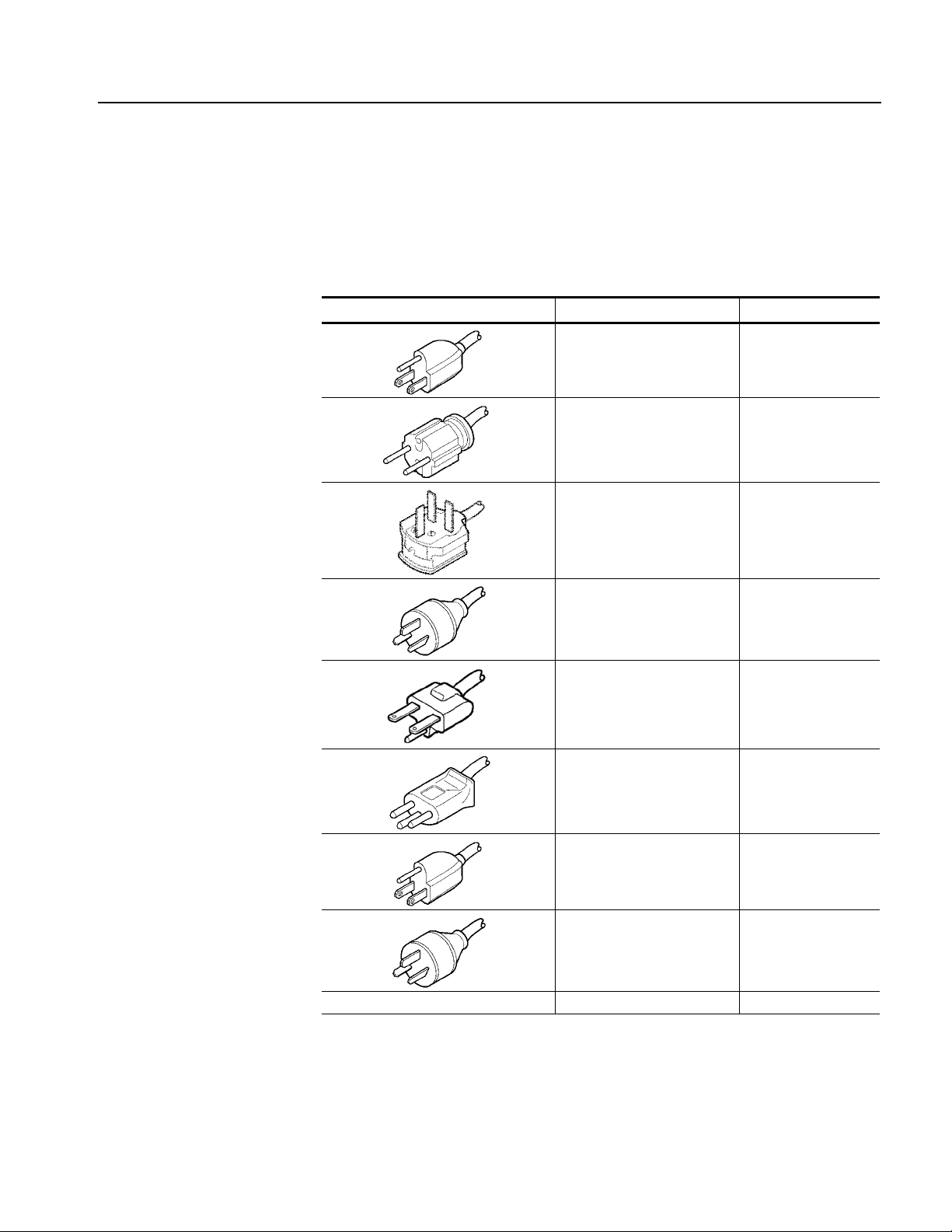
Table 1-1: Power cord identification
Plug configuration Normal usage Option number
North America
115 V
Universal Euro
220 V
United Kingdom
240 V
Australia
240 V
Standard (A0)
A1
A2
A3
North America
250 V
Switzerland
240V
Japan
100 V
China
240 V
No power code supplied. A99
A4
A5
A6
A10
RTX100A ISDB-T RF Signal Generator User Manual 1-3
Page 24

Getting Started
Optional Accessories
Options
The following items are optional accessories:
RTX100A ISDB-T RF Signal Generator Service Manual, Tektronix part
number 071-1757-XX.
WFM7F05 rackmount kit
1700F06 blank panel
The R TX100A can be ordered with the following options:
Instrument Option
Service Options
Power Cord Options
The following instrument option is available for the RTX100A:
Option SC: Adds the Scheduler software.
The following service options are available for the RTX100A:
Option C3: Provides calibration services for 3 years.
Option C5: Provides calibration services for 5 years.
Option D1: Provides calibration data.
Option D3: Provides calibration data for 3 years.
Option D5: Provides calibration data for 5 years.
Option R3: Extends the instrument warranty to 3 years.
Option R5: Extends the instrument warranty to 5 years.
See Table 1-1 on page 1-3.
1-4 RTX100A ISDB-T RF Signal Generator User Manual
Page 25

Initial Product Inspection
Perform the following product inspection procedure when you receive your
instrument:
1. Inspect the shipping carton for external damage, which indicates possible
2. Remove the RTX100A from the shipping carton.
3. Check that the instrument has not been damaged in transit. The exterior should
NOTE. Save the shipping carton and packaging materials for instrument
repackaging in case shipment becomes necessary.
4. Verify that the shipping carton contains the instrument, the standard
Getting Started
damage to the instrument.
not have any scratches or impact marks. Prior to shipment the instrument is
thoroughly inspected for mechanical defects.
accessories, and any optional accessories that you ordered.
Installation
Environment Operating
Requirements
5. Perform the functional check procedure (refer to Functional Check Procedur e
on page 1-10) after installing the instrument.
Contact your local Tektronix Field Office or representative if there is a problem
with your instrument or if your shipment is incomplete.
Before you install the instrument, refer to the General Safety Summary section at
the front of this manual for power source, grounding, and other safety information.
Verify that the location of your installation has the proper op erating environment.
CAUTION. Damage to the instrument can occur if this instrument is powered on at
temperatures outside of the specified temperature range.
RTX100A ISDB-T RF Signal Generator User Manual 1-5
Page 26
Getting Started
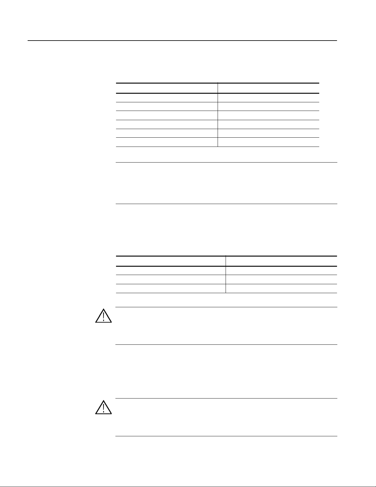
Table 1-2: Environmental operating requirement
Characteristics Specifications
RTX100A ambient temperatures from +5 °C to + 40 °C
RTX100A relative humidity from 20% to 80%
Clearance on top 5.0 cm (2 in)
Clearance on left side 5.0 cm (2 in)
Clearance on right side 5.0 cm (2 in)
Clearance in rear (from the fan guard) 5.0 cm (2 in)
NOTE. If you are installing the instrument in a dedicated rack, refer to the
instruction sheet that comes with the rackmounting kit for proper installation
procedures.
When the RTX100A is mounted in a 19-inch rack, verify that there is at least one
unit of clearance above the RTX100A.
AC Line Voltage
Requirement
Power Cord Requirement
Check that your location provides the proper electrical power requirements as
listed in Table 1-3.
Table 1-3: AC line power requirement
Parameter Description
Line voltage range 100 to 240 V
Line frequency 50/60 Hz
Maximum power 180 VA
CAUTION. The instrument does not have a power switch, but does have an
on/standby switch. When you connect the power cable to the AC line connector,
power is applied to the power supply standby circuit of the instrument. Read all
instructions on pages 1-7 and 1-8 before plugging the power cable into a power
source.
Refer to Table 1-1 on page 1-3 to verify that you are using the proper power
cord for your location. Connect the power cord from the rear-panel power
connector to the power system.
CAUTION. The instrument is shipped with a power cord appropriate for use with
your power systems (normal 115 V power system or 230 V power system). If the
instrument is to be used with a power system other than that specified in the order,
the power cord must be replaced with one appropriate for the power source used.
Refer to Table 1-1 for a listing of available power cords.
1-6 RTX100A ISDB-T RF Signal Generator User Manual
Page 27
Getting Started
VGA
LAN
Com
Printer
IEEE 1394b
SPI
In/Out
Clock/Ref
In
RF Out
ASI In
ASI Out
Trig
In/Out
Applying Power to the
Instrument
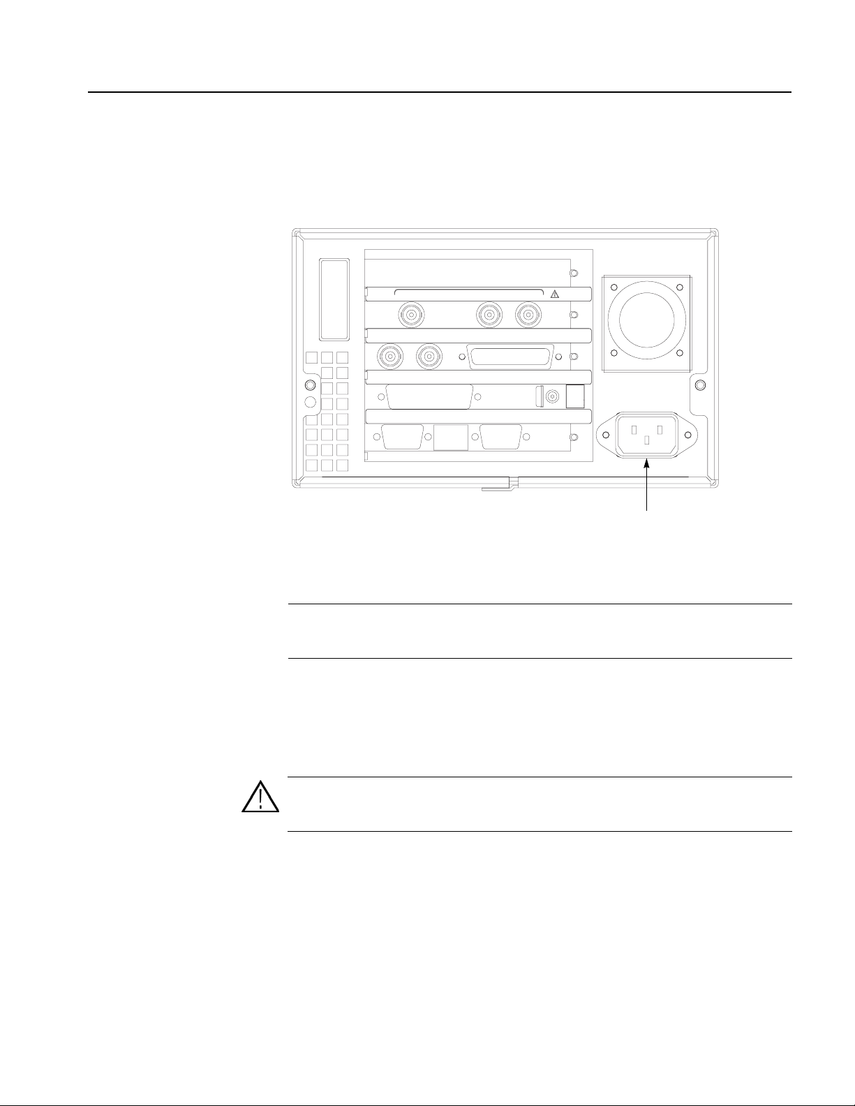
After you have verified the operating environment, AC line, and power cord
requirements, plug the power cord into the power connector on the rear panel (see
Figure 1-1), and then plug the power cord into the local power source.
Power connector
Figure 1-1: Rear-panel power connector
NOTE. To make a selection in a Windows dialog box after you power on the
instrument, connect a mouse to the USB connector on the front panel before you
power on.
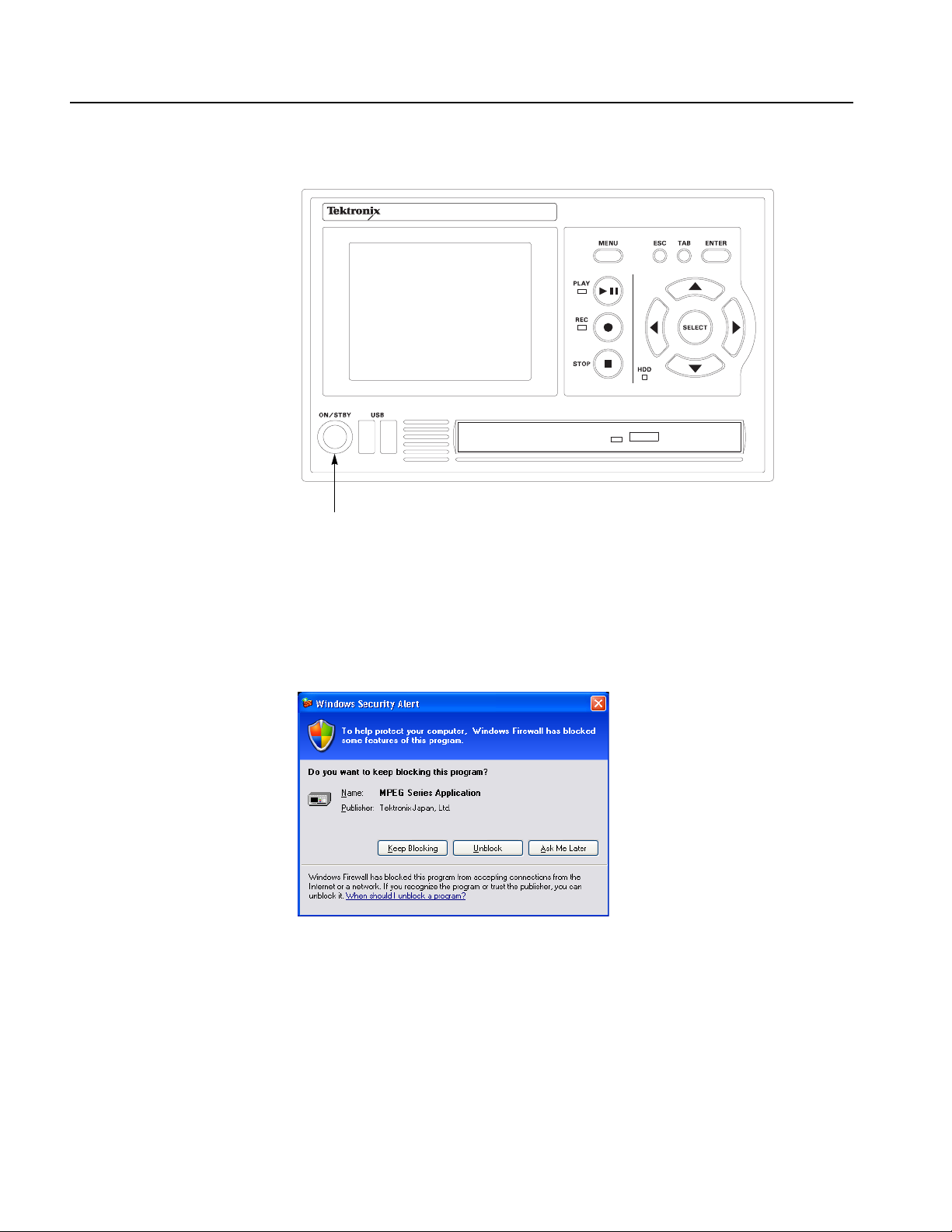
Power On. Press the ON/STBY switch (see Figure 1-2) to power on the instrument.
After you power on the instrument, verify that the fan on the rear panel is operating.
To verify that the fan is operating, place your hand behind the right side of the
instrument. You should be able to feel the fan’s air flow.
CAUTION. Do not operate the instrument if the cooling fan does not operate when
you turn the instrument on. Serious damage to your instrument can occur from
overheating if the cooling fan is not operating.
RTX100A ISDB-T RF Signal Generator User Manual 1-7
Page 28
Getting Started
RTX100A I S DB -T S i gnal G enerator
ON/STBY switch
Figure 1-2: Front-panel On/STBY switch
The first time you power on the instrument, the Windows Security Alert dialog
box appears as shown in Figure 1-3. This dialog box appears when a program tries
to use the resources or the ports on the system that are covered by the firewall.
Figure 1-3: Windows Security Alert dialog box
Click the Unblock button so that Windows allows the program (MPEG Series
Application) to run.
When you click the Unblock button, the MTX100A application window (Play
screen) is displayed.
1-8 RTX100A ISDB-T RF Signal Generator User Manual
Page 29

Repacking for Shipment
Getting Started
When you ship this instrument, use the original packaging material if possible. If
the original packaging is unfit for use or is not available, repackage the instrument
using the following procedure:
1. Obtain a corrugated cardboard shipping carton ha ving inside dimensions at
least six inches greater than the instrument dimensions and having a carton test
strength of at least 125 kg (275 pounds).
2. If the instrument is being shipped to a Tektronix Service Center for repair or
calibration, attach a tag to the instrument showing the following information:
The owner of the instrument (with address).
The name of a person at your firm who may be contacted if additional
information is needed.
The complete instrum e nt type and serial number.
A description of the service required.
3. Wrap the instrument with polyethylene sheeting or equivalent to protect the
outside finish and prevent entry of packing materials into the instrument.
4. Cushion the instrument on all sides by tightly packing dunnage or urethane
foam between the carton and the instrument, allowing for three inches
(7.62 cm) of padding on each side (including top and bottom).
5. Seal the carton with shipping tape or with an industrial stapler.
6. Mark the address of the Tektronix Service Center and your return address on
the carton in one or more prominent locations.
RTX100A ISDB-T RF Signal Generator User Manual 1-9
Page 30
Getting Started
Functional Check Procedure
Perform the following procedure if you are operating the instrument for the first
time (to verify that the instrument shipped without damage) or you suspect that the
instrument is not working properly:
NOTE. Before you perform this procedure, install the RTX100A using the
instructions listed in Installation starting on page Up Windows XP Professional.
1. Connect the RTX100A to a power source, and then turn the instrument on
using the ON/STBY switch.
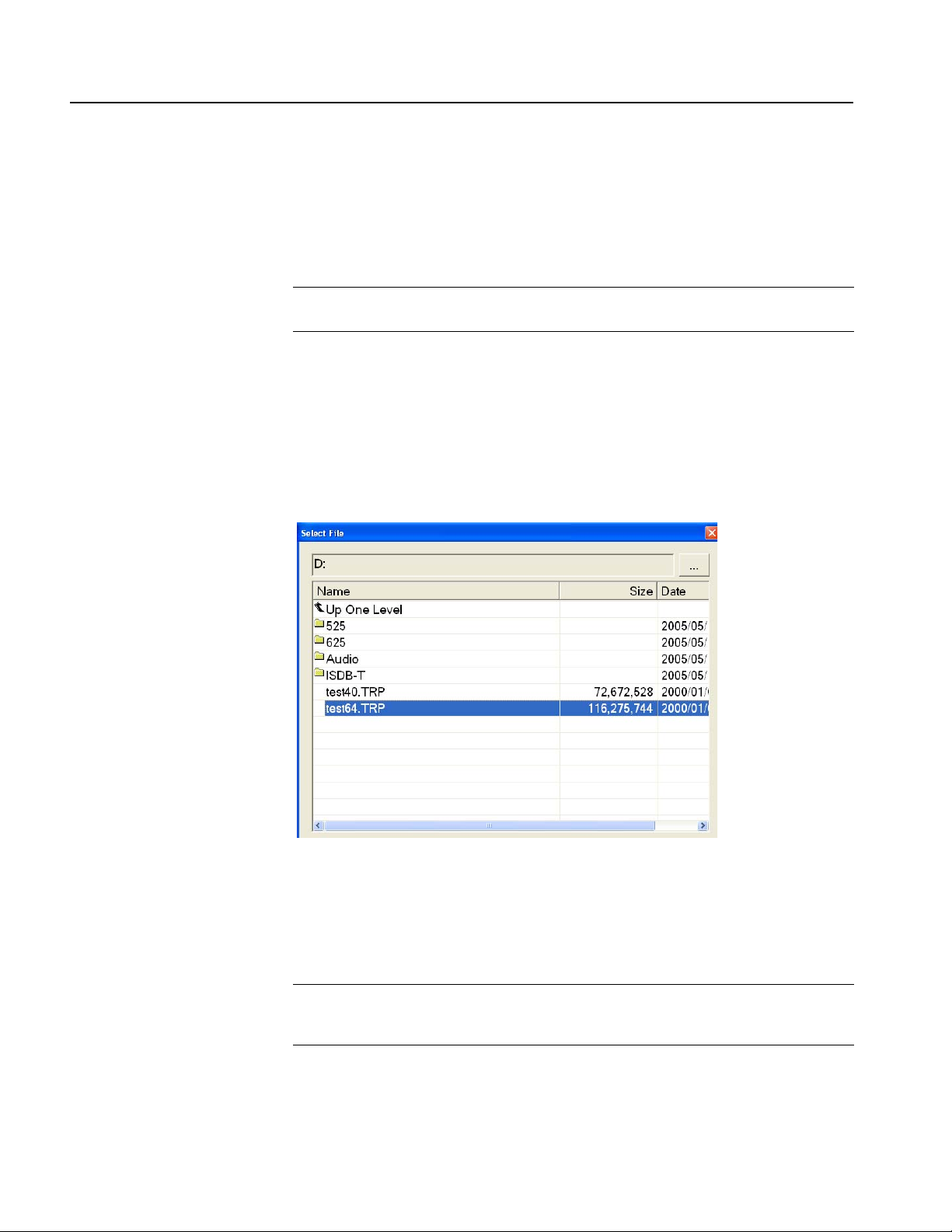
2. Press the front-panel MENU button to display the File menu command list.
3. Press the up (
then press the ENTER button to open the Select File dialog box shown in
Figure 1-4.
Figure 1-4: Select File dialog box
S) or down (T) arrow button to select Open from the list, and
4. Press the up (
then press the ENTER button. The hierarchy view of the transport stream file
will be displayed on the screen.
NOTE. You can select the test40.TRP file in step 4 of this procedure if you need to
decrease the bit rate of the transport str eam due to performance restrictions in your
decoder.
1-10 RTX100A ISDB-T RF Signal Generator User Manual
S) or down (T) arrow button to select the test64.TRP file, and
Page 31

Getting Started
5. Connect the interface cable provided with the instrument between the SPI
IN/OUT connector on the RTX100A rear panel and the SPI IN connector on
an MPEG decoder. See Figure 1-5.
6. Connect the decoder to a picture monitor.
7. Press the RTX100A PLAY button to start the transport stream output. When
transport stream output is started, the Play Status indicator appears on the
screen.
8. Check that the picture from the transport stream is displayed correctly on the
picture monitor.
RTX100A rear panel
Interface cable
MPEG decoder
SPI in
Output
Picture monitor
Input
Figure 1-5: Equipment connection for the functional check
RTX100A ISDB-T RF Signal Generator User Manual 1-11
Page 32

Getting Started
Windows Operations
All of the functions of the RTX100A are performed as an application (RTX100A
application) on the Windows XP operating system. Therefore, if you connect the
keyboard and mouse provided with the instrument to the front-panel USB
connectors, you can operate the R TX100A system with the same environment as a
Windows PC.
Operation on the
Play/Record Screen
Displaying the Windows
Screen (Desktop)
File Operation
System Settings
When you have connected a keyboard and mouse to the instrument, you can use
them to make menu selections and parameter settings in the Play/Record screen.
These operations behave in the same manner as the other Windows applications.
To display the Windows screen (Desktop), select Minimize or Exit from the File
menu in the Play screen or Record screen. For Minimize, the RTX100A application
window minimizes and the W indows XP desktop appears. For Exit, the RTX100A
application exits and the Windows XP desktop appears.
There are no menu commands to manage file operations in the RTX100A
application. Perform the file operations such as copy, delete, or upload/download
on Windows. Refer to W indows XP Online Help or other documentation about file
operations.
The R TX100A application is placed in the C:\ProgramFiles\Tektronix\Mpeg
Player folder. The sample transport stream files (test64.TRP and test40.TRP) are
placed on D: drive (Volume D).
This manual describes only the settings for connecting to an Ethernet network.
Refer to Windows XP Online Help or other documentation about other system
settings.
1-12 RTX100A ISDB-T RF Signal Generator User Manual
Page 33

Operating Basics
Page 34

Page 35

Operating Basics
Functional Overview
This section explains the basics of operating the RTX100A. The information is
divided into the following subsections:
Functional Overview contains descriptions of the front-panel controls, the
rear-panel connectors, and elements of the display.
Basic Menu Operation provides the basic concepts of how to operate the
R TX100A using the menus and front-panel buttons, and how to enter numeric
input into dialog boxes.
Tutorials contains procedures that show you how to output and record a
transport stream.
This subsection contains descriptions of the front-panel controls and the rear-panel
connectors.
Front-panel Controls
Figure 2-1 shows the locations of the front-panel controls.
ON / STBY Power Switch. Powers on or off the instrument.
CAUTION. If you power off the instrument using the ON/STBY power switch, the
current instrument settings are not saved (this operation corresponds to an
emergency shutdown in Windows XP). To prevent data loss, use the Shutdown
command from the File menu to power off the instrument.
USB Connectors. USB2.0 connectors to connect the keyboard and mouse provided
with the instrument for Windows operations. You can also connect other USB
devices.
DVD±RW Drive. DVD drive with capability of reading and writing to the following
standards: DVD-R/RW, DVD+R/RW, and CD-R/RW.
RTX100A ISDB-T RF Signal Generator User Manual 2-1
Page 36

Operating Basics
STOP button REC button PLAY button MENU button
ESC/TAB/ENTER
buttons
SELECT button
RTX100A I S D B -T S ignal Gener ator
ON/STBY
power switch
USB connector
Figure 2-1: RTX100A front panel
DVD±RW drive HDD access
indicator
Arrow buttons
MENU Button. Use this button to toggle the display of the menu command list on or
off.
PLAY Button. Press this button to start stream output. When the Record screen is
displayed, use this button to switch to the Play screen. When this button is pressed
during stream output, the stream output pauses. Press the button again to start the
stream output.
When an M-TMCC transport stream is selected, the RTX100A outputs the stream
from the start packet in the super frame to the maximum number of packets that can
be looped as an integral multiple of the number of super frames. When an ISDB-T
transport stream is selected, the RTX100A outputs the stream from the start packet
in the OFDM (Orthogonal Frequency Division Multiplexing) frame to the
maximum number of packets that can be looped as 2 X N of the number of OFDM
frames. If any transport streams within the ISDB-T transport stream have different
modulation parameters, select Non TS from the Packet Size command in the Play
menu (refer to page 3-5).
2-2 RTX100A ISDB-T RF Signal Generator User Manual
Page 37

Operating Basics
The status indicator at the left side of the button lights when stream data is being
output. The indicator blinks when the stream output pauses.
REC Button. Press this button to record the stream data being applied. If a broadcast
transport stream is applied to the ASI IN connector, pressing this button starts
outputting an RF modulated signal. When the Play screen is displayed, use this
button to switch to the Record screen.
The status indicator at the left side of the button blinks when a sync word is being
detected, or when the pretrigger portion of the stream data has been recorded.
STOP Button. This button performs the following functions:
If this button is pressed while a stream data is being output, the data output
stops.
If this button is pressed while the pretrigger portion is filled and the instrument
waits a trigger event or the posttrigger portion is being recorded, the recorded
data is stored in a file.
ESC/TAB/ENTER Buttons. These buttons perform the following functions:
The ESC button is used to cancel the selected operation. When any menu
command list is displayed, it closes the command list temporarily.
The TAB button is used to move through a dialog box.
The ENTER button is used to execute the selected menu command or enable
all setting changes in a dialog box.
SELECT Button. Use the SELECT button to enable or disable any setting changes
in a dialog box. It is also used to open the keypad, where you can enter numeric
values for a text box.
When an ISDB-T file is selected in the Play screen or an ISDB-T signal is captured
in the Record screen, pressing this button causes the ISDB-T Information dialog
box to appear.
Arrow Buttons. Use the arrow buttons to maneuver on the LCD display. For
example, you can use these buttons to move the Icon cursor or to move among the
menu selections.
HDD Access Indicator. This indicator lights when the hard disk drive or the
CD-R/W drive is in operation.
RTX100A ISDB-T RF Signal Generator User Manual 2-3
Page 38

Operating Basics
Rear-panel Connectors
Figure 2-2 shows the locations of the RTX100A rear-panel connectors.
Clock/Ref In RF Out Trig In/Out
RF Out
VGA
Trig
In/Out
Printer
LAN
Clock/Ref
In
ASI In
In/Out
Com
ASI In
SPI
ASI Out SPI In/Out
ASI Out
IEEE 1394b
VGA LAN Com IEEE 1394b PowerPrinter
Figure 2-2: RTX100A rear panel
RF Out. Use this BNC connector to output an RF signal.
NOTE. The RF signal output is only available when a broadcast transport stream
is being output or applied.
ASI In. Use this BNC connector to input an ASI (Asynchronous Serial Interface)
signal. When you want to output an RF signal using an external broadcast transport
stream, apply the transport stream to the connector.
ASI Out. Use this BNC connector to output an ASI (Asynchronous Serial Interface)
signal.
2-4 RTX100A ISDB-T RF Signal Generator User Manual
Page 39

Operating Basics
Clock/Ref In. Use this BNC connector to input an external reference signal or clock
signal to the RTX100A. Refer to Appendix A: Specifications for detailed
information about the signal specification.
NOTE. Use a continuous signal for an external reference or clock signal.
Trig In/Out. Use this BNC connector to input an external trigger event for stream
recording or output a 27 MHz reference clock signal or an ISDB-T frame pulse
signal. You can change the configuration from the Play menu (refer to the Play
Menu on page 3-5).
Refer to Appendix A: Specifications for detailed information about the signal
specification.
SPI In/Out. Use this 25-pin D-sub connector to input and output an SPI
(Synchronous Parallel Interface) signal. Refer to Appendix A: Specifications for
detailed information about the input voltage range for the signal.
Printer. Use this 25-pin D-sub connector to connect a printer. This interface
supports the IEEE 1284 parallel port standard.
IEEE1394b. Use this connector to connect an IEEE 1394b device such as an
external hard disk drive.
VGA . Use this 9-pin D-sub connector to display the instrument screen to an external
monitor.
The VGA output is automatically enabled only when you power on the instrument
with an external monitor connected. If you want to enable the VGA output after
powering on the instrument, perform the following steps:
1. Minimize the Play screen to display the Windows XP desktop.
2. Click the Intel(R) Extreme Graphics 2M icon (see below) at the right side of
the taskbar.
3. Select Graphic Options > Output To > Intel(R) Dual Display Clone >
Monitor+Notebook from the displayed menu.
RTX100A ISDB-T RF Signal Generator User Manual 2-5
Page 40

Operating Basics
LAN. (10/100/1000 Base-T). Use this connector to connect the RTX100A to your
local Ethernet network.
Com. This 9-pin D-sub connector provides a serial interface for instrument control.
Power Connector. Use this connector to apply power to the instrument using the
supplied power cord.
Display Elements
There are two types of display screens to operate the RTX100A; the Play screen
and the Record screen.
Play screen is used to output the selected stream. When you power on the
instrument, this screen will display the last screen showing before powering
down.
Record screen is used to record the input stream. When you press the REC
button or select the Record command from the File menu while the Play screen
is displayed, the screen switches to the Record screen.
This subsection explains the display elements that make up the Play and Record
screens.
Figure 2-3 shows the location of display elements of the Play screen. The display
elements of the Record screen are the same as that of the Play screen.
2-6 RTX100A ISDB-T RF Signal Generator User Manual
Page 41

Operating Basics
Menu bar
Toolbar
Icon cursor
Hierarchical
display of the
transport stream
Play status
indicator
Status bar
Menu
Remote connection status icons
Scroll bar
Menu commands list
Figure 2-3: Elements of the Play screen
Menu Bar. The Menu bar displays the names of the menus that can be used in the
Play or Record screen. Press the MENU button to enable or disable the menus.
Refer to Using the Menus on page 3-3 for detailed information about the menus.
RTX100A ISDB-T RF Signal Generator User Manual 2-7
Page 42

Operating Basics
Too lb ar. The toolbar provides shortcut buttons for many of the most often used
menu commands. Click a toolbar button to select the corresponding command.
You can toggle the toolbar display on and off using Toolbar command in the View
menu.
Refer to Toolbar Buttons on page 3 -32 for detailed information about the funct ion
of each toolbar button.
Hierarchy Display. Each icon in the hierarchy display represents an element of the
stream. The hierarchy text contains a description of the associated icon.
Refer to Hierarchy Display on page 3-33 for detailed information about the
hierarchy icons.
Icon Cursor. The icon cursor appears as a red box around an icon in the hierarchy
to indicate the currently selected icon.
Use the up (S) or down (T) arrow button to move the icon cursor between icons.
When the icon cursor is at the top or bottom of the hierarchy display , the hierarchy
scrolls to show additional elements of the stream when applicable.
Play/Record Status Indicator. The play status indicator (see Figure 2-4) is displayed
while the selected stream is being output. It shows the output status of the selected
stream: the progress of the stream output, the output source, the operational status,
and the elapsed time.
The record status indicator is displayed while the input stream is being recorded. It
shows the record status of the input stream: the progress of the stream record, the
record target, and the elapsed time.
1
23
4
Figure 2-4: Play status indicator
The play/record status indicator shows the following information:
1. Position Indicator . In the Play screen, this indicator shows the progress of the
stream output using the duration gauge. In the Record screen, this indicator
shows the progress of the stream record using the duration gauge.
2-8 RTX100A ISDB-T RF Signal Generator User Manual
Page 43

Operating Basics
The duration gauge is updated every 1 second. If you output a stream with a
repetition rate of around 3 seconds, the gauge may not be displayed correctly.
2. Output Source/Record Target. In the Play screen, this indicator shows the
output source used to output the selected stream. In the Record screen, this
indicator shows the record target used to record the input stream.
Either of the following icons are displayed according to the selected output
source or record target:
This icon shows that the hard disk is the output source or record target.
This icon shows that the RAM is the output source or record target.
3. Operation Status. Shows the current operation status of the instrument.
In the Play screen, the following icons are used:
This icon shows that the selected stream is being output.
This icon shows that the stream output is being stopped.
This icon shows that the selected stream is being read from the hard disk to the RAM.
In the Record screen, the following icons are used:
This icon shows that the captured stream is being recorded.
This icon shows that the stream record is being stopped.
This icon shows that the RTX100A waits for a trigger event.
This icon shows that a trigger event occurs.
This icon shows that the captured stream is being processed on the hard disk.
This icon shows that the captured stream is being saved from the RAM to the hard disk.
RTX100A ISDB-T RF Signal Generator User Manual 2-9
Page 44

Operating Basics
4. Elapsed Time. In the Play screen, this box displays the elapsed time of the
current stream data output.
In the Record screen, this box displays the elapsed time since the input stream
is recorded.
Scroll Bar. The scroll bar appears when there is a hierarchy display to show the
relative position of the hierarchy of the stream.
NOTE. After you scroll a hierarchy display in the Record screen, the display may
be out of focus. If this is the case, select an icon cursor on the display to refocus.
Status Bar. The status bar (see Figure 2-5) contains several indicators that display
general information about the transport stream output or record status .
12 3 4 56
Figure 2-5: Status bar
The Status bar shows the following information:
1. Standard. In the Play screen, this indicator shows the standard used to display
the selected stream (MPEG2, ARIB, DVB, ATSC, S-TMCC, M-TMCC,
ISDB-T, or Non TS). In the Record screen, this indicator shows the standard
used to display the input stream.
2. Packet Size. In the Play screen, this indicator displays the packet size in bytes
(188, 204, 208, or Non TS) of the stream output. In the Record screen, this
indicator displays the packet size in bytes of the input stream.
3. Clock Source. This indicator displays the source of the reference clock
(internal or external) used for the stream output.
4. Bit Rate. In the Play screen, this indicator displays the bit-rate (in Mbps) of the
stream output. In the Record screen, this indicator displays the bit-rate (in
Mbps) of the input stream.
5. RAM free space. In the Play screen, this indicator shows the RAM free space
that can be used to output the selected stream. In the Record screen, this
indicator shows the RAM free space that can be used to record the input
stream.
2-10 RTX100A ISDB-T RF Signal Generator User Manual
Page 45

Operating Basics
6. Output Source/Record Target. In the Play screen, this indicator shows the
output source used to output the selected stream. In the Record screen, this
indicator shows the record target used to record the input stream.
This indicator is the same as the output source/record target indicator of the
Play/Record Status indicator.
RF Status Display. Displays a parameter and an icon related to the RF output.
12
Figure 2-6: RF Status Display
1. This indicator display the center frequency (UHF channel number) for the RF
output. This value can be set using the RF Parameter command in the
ISDB-T/ASI menu.
2. This icon appears while outputting an RF signal.
Remote Connection Status Icons. The remote connection status icons appear when
a TCP/IP connection for remote control is established. The right icon shows the
status of the TCP/IP connection (this icon is always displayed when the TCP/IP
connection is established), and the left icon shows the lock status of the front-panel
buttons and mouse input.
There are two display states:
This shows that the TCP/IP connection for remote control is established.
This shows that the TCP/IP connection for remote control is established and the
front-panel buttons and mouse input are locked by the :SYSTem:KLOCk:STATe ON
command.
To reset the lock status, send the :SYSTem:KLOCk:STATe OFF command or
press the ESC button on the front panel (if a keyboard is connected, press the Esc
key).
When the TCP/IP connection is closed, the remote status icons disappear.
RTX100A ISDB-T RF Signal Generator User Manual 2-11
Page 46

Operating Basics
Basic Menu Operation
This section describes the basics of using the RTX100A menu and the methods for
entering numeric input in the various dialog boxes.
The menus are displayed in the menu bar at the top of the Play or Record screen.
You can operate these menus using the front panel MENU button, ESC button,
TAB button, ENTER button, and the arrow buttons (see Figure 2-7).
ESC button TAB button ENTER button
MENU button
Arrow buttons
Figure 2-7: Front panel showing the menu controls
Accessing Menu Commands. To access any menu command, press the MENU
button. When you press the MENU button, the File menu command list opens.
Use the up (S) or down (T) arrow button to move through the command list. Press
the ENTER button to execute the selected command.
Use the left (W) or right (X) arrow button to select the desired menu. Press the ESC
button to close the command list temporarily.
2-12 RTX100A ISDB-T RF Signal Generator User Manual
Page 47

Operating Basics
Press the MENU button again to close the menu command list.
NOTE. When you press the left arrow button while the File menu is displayed or
when you press the right arrow button while the Utility menu is displayed, the
Windows Contr ol menu appears.
Display States of the Menu Commands. The menu commands can have the
following three display states as shown in Figure 2-8:
A command followed by “X” indicates that a corresponding submenu will be
displayed after you press the ENTER button or the right (X) arrow button.
A command followed by an ellipsis (...) indicates that a corresponding dialog
box will open after you press the ENTER button.
A command name by itself will be executed after you press the ENTER button.
A corresponding submenu will be
displayed
Numeric Input
A corresponding dialog box will be
displayed when this command is executed
The displayed command will be executed
immediately
Figure 2-8: Display status of the menu commands
You can enter numeric values in the displayed dialog box by using the keypad or
by using the arrow buttons.
Numeric Input Using the Keypad. Perform the fo llowing procedure to input numeric
values by using the keypad. Figure 2-9 shows the keypad.
1. Open a dialog box including the text box in which you want to change a
parameter.
2. Press the TAB button repeatedly to select (highlight) the numeric parameter
you want to change in the open dialog box.
RTX100A ISDB-T RF Signal Generator User Manual 2-13
Page 48

Operating Basics
3. Press the SELECT button to open the keypad (see Figure 2-9).
Numeric input box
Clear key
Backspace
Cancel key
Enter key
Figure 2-9: Keypad
4. Press the TAB button or the arrow buttons to move the dotted line box onto the
number you want to input (when the keypad first opens, the box is located on
the ENT key).
5. Press the SELECT button. This displays the selected number in the numeric
input box.
6. Repeat steps 4 and 5 to input the desired parameter value.
7. Press the ENTER button (or select the ENT key and then press the SELECT
button). This saves the new value in the numeric input box and closes the
keypad.
Numeric Input Using the Arrow buttons. Per form the following procedure to change
a value by using the arrow buttons:
1. Open the dialog box containing the text box where you want to change a
parameter.
2. Press the TAB button repeatedly to select the numeric parameter you want to
change in the open dialog box.
3. Press the left (W) arrow button to begin editing the parameter. This highlights
the last digit.
4. Press the left (W) or right (X) arrow button to move the highlighted cursor to
the value you want to change.
5. Press the up (S) or down (T) arrow button to increase or decrease the value.
6. Repeat steps 4 and 5 to enter all of the desired values. T o add a digit, press the
left (W) arrow button.
2-14 RTX100A ISDB-T RF Signal Generator User Manual
Page 49

7. After you change all of the values, press the ENTER button.
About the Data Output Source
When you output the selected stream data, you can select either the hard disk or the
RAM as the output source. This subsection describes the operation of the
RTX100A when each output source is selected.
Operating Basics
RAM
Hard Disk
When you select the RAM as the output source, the RTX100A performs the
following:
When data output rate is less than or equal to 120 Mbps, the R TX100A output s
the first stream data while transferring the data from the hard disk to the RAM
and then continuously outputs the data from the RAM using looping methods.
When data output rate is more than 120 Mbps, the RTX100A continuously
outputs a stream data from the RAM using looping methods after the data is
completely transferred from the hard disk to the RAM.
If you select the RAM as the output source, you cannot output the data over the
RAM free space for the data output (maximum 256 MB). This RAM free space is
displayed on the status bar. Refer to Status Bar on page 2-10, for more information
about the status bar.
If you select the hard disk (Disk) as the output source, the RTX100A always
outputs the selected stream data from the hard disk regardless of the data output
rate. When the reading speed of the hard disk cannot overtake the data output rate,
the error message “Error: Output Buffer Empty” appears.
Use the Source command in the Play menu to select the output source. Refer to
Play Menu on page 3-5 for more information about the Play menu.
You can see the currently selec ted output sourc e in the status bar. Refer to Status
Bar on page 2-10, for more information about the status bar.
RTX100A ISDB-T RF Signal Generator User Manual 2-15
Page 50

Operating Basics
2-16 RTX100A ISDB-T RF Signal Generator User Manual
Page 51

Tuto ri a l s
Required Equipment
This section provides the following tutorials to familiarize you with the basic
functions of the RTX100A:
Outputting a transport stream
Recording a transport stream
Outputting an RF modulated broadcast transport stream
NOTE. These tutorials do not cover all the features and functions of the RTX100A.
The tutorials are intended to introduce you to the operations r equir ed to execute the
instrument's basic functions.
Refer to the Reference section for detailed descriptions of the menus and functions
used in these procedures.
Before you perform these tutorials, make sure that the RTX100A is properly
installed. Refer to Installation on page 1-5.
Table 2-1 lists the equipment required to perform the tutorials. Accuracy of
alternate equipment should equal or exceed that of the example instruments and
accessories. Using inadequate equipment may result in inaccurate measurements.
Table 2-1: Tutorial recommended test equipment and accessories
Item No. Requirement Example
MPEG test system 1 Real-time transport stream analyzer Tektronix MTS400 Series MPEG Test
Systems or equivalent
ISDB-T receiver 1 Panasonic VP-8480A ISDB-T Analyzer
75 Ω BNC cable 1 Length: 42 inches Tektronix part number 012-0074-00
RTX100A ISDB-T RF Signal Generator User Manual 2-17
Page 52

Tutorials
Outputting a Transport Stream
The hard disk drive of the RTX100A is shipped with files containing
factory-supplied samples of transport streams. This tutorial opens one of these
sample files and outputs the transport stream.
Perform the following steps to select and output a stored transport stream:
1. Press the front-panel PLAY button to display the Play screen.
2. Press the MENU button to open the File menu.
3. Press the up (S) or down (T) arrow button to select Open from the menu, and
then press the ENTER button to open the Select File dialog box shown in
Figure 2-10.
Figure 2-10: Select File dialog box
4. Press the up (S) or down (T) arrow button to select the test64.TRP file, and
then press the ENTER button. This displays the hierarchy view of the transport
stream file shown in Figure 2-11.
2-18 RTX100A ISDB-T RF Signal Generator User Manual
Page 53

Tutorials
Figure 2-11: Hierarchy view of the transport stream file
5. Connect the 75 Ω BNC cable between the ASI Out connector on the
RTX100A rear panel to the ASI In connector of the MPEG test system.
6. Press the RTX100A PLAY button to start the transport stream output.
When transport stream output is started, the play status indicator (see Figure 2-12)
appears and the PLAY indicator at the left side of the button lights.
Figure 2-12: Play status indicator
7. Set up the MPEG test system to monitor the transport stream output from the
RTX100A. Figure 2-13 shows the transport stream data displayed on an MPEG
test system.
8. Press the STOP button on the RTX100A to stop the transport stream output.
Observe that the Play Status indicator disappears.
RTX100A ISDB-T RF Signal Generator User Manual 2-19
Page 54

Tutorials
Figure 2-13: Transport stream display from an MPEG test system
Recording a Transport Stream
This tutorial captures a transport stream being applied into the ASI In connector
and records it on the hard disk as a file.
Perform the following steps to capture a transport stream and record it in the hard
disk as a file:
1. Press the front-panel REC button to display the Record screen.
Since no signal is being applied at this time, the No Signal message appears on
the top of the screen (see Figure 2-14).
Figure 2-14: No Signal message
2-20 RTX100A ISDB-T RF Signal Generator User Manual
Page 55

Tutorials
2. Connect the 75 Ω BNC cable between the ASI In connector on the RTX100A
rear panel to the ASI OUT connector of the MPEG test system.
3. Output a transport stream from the MPEG test system.
When transport stream output is started, the hierarchy view of the transport
stream is displayed on the Record screen of the RTX100A.
4. Press the RTX100A REC button.
When you press the button, the record status indicator (see Figure 2-15)
appears and the REC indicator at the left side of the button lights.
Figure 2-15: Record status indicator
After the transport stream record is completed, the record status indicator
disappears, and the transport stream is saved automatically with a file name which
shows the current date (yy:mm:dd).
RTX100A ISDB-T RF Signal Generator User Manual 2-21
Page 56

Tutorials
Outputting an RF modulated broadcast transport stream
The hard disk drive of the RTX100A is shipped with files containing
factory-supplied samples of broadcast transport streams. This tutorial converts a
broadcast transport stream into an RF signal and outputs it from the RF Out
connector.
1. Press the front-panel PLAY button to display the Play screen.
2. Select the Open command from the File menu to open the Select File dialog
box.
3. Press the up (S) or down (T) arrow button to select the ISDB-T folder, and
then press the ENTER button. This displays the content of the ISDB-T folder.
4. Press the up (S) or down (T) arrow button to select ISDB_T_M1.rmx, and
then press the ENTER button. This displays the hierarchy view of the selected
transport stream file.
You can display ISDB-T parameters of the transport stream by pressing the
front-panel SELECT button or by pressing the space key of th e key bo ard (if
it is connected).
5. If necessary, change RF parameters:
a. Select RF Parameter from the ISDB-T/ASI menu to open the ISDB-T
RF Parameter dialog box shown below.
b. In the dialog box, select a center frequency. You can select from
channel 13 to channel 62 as a center frequency. Refer to Table 2-2 for
information about the available UHF channels and their frequencies.
6. Connect the 75 Ω BNC cable between the RF Out connector on the RTX100A
rear panel and the RF INPUT connector on the ISDB-T receiver.
7. Press the RTX100A PLAY button to start the transport stream output.
8. Use the ISDB-T receiver to check that the RF modulated broadcast transport
stream is output from the RF Out connector.
2-22 RTX100A ISDB-T RF Signal Generator User Manual
Page 57

Tutorials
Table 2-2: UHF channel number and frequency
Channel Frequency (MHz) Channel Frequency (MHZ) Channel Frequency (MHz)
13 473.143 30 575.143 47 677.143
14 479.143 31 581.143 48 683.143
15 485.143 32 587.143 49 689.143
16 491.143 33 593.143 50 695.143
17 497.143 34 599.143 51 701.143
18 503.143 35 605.143 52 707.143
19 509.143 36 611.143 53 713.143
20 515.143 37 617.143 54 719.143
21 521.143 38 623.143 55 725.143
22 527.143 39 629.143 56 731.143
23 533.143 40 635.143 57 737.143
24 539.143 41 641.143 58 743.143
25 545.143 42 647.143 59 749.143
26 551.143 43 653.143 60 755.143
27 557.143 44 659.143 61 761.143
28 563.143 45 665.143 62 767.143
29 569.143 46 671.143 --- ----------
Note for RF Modulation
Output
When you output a broadcast transport stream from the RTX100A, note the
following:
You cannot perform RF modulation for transport streams other than broadcast
transport streams.
If there are a number of modulation parameters in the broadcast transport
stream currently being output, the RF modulation is distorted for about two
seconds at the parameter changing points.
The RTX100A does not support DQPSK modulation. If DPQSK modulation
is used in the selected broadcast transport stream, the stream is modulated to
QPSK and then output.
RTX100A ISDB-T RF Signal Generator User Manual 2-23
Page 58

Tutorials
2-24 RTX100A ISDB-T RF Signal Generator User Manual
Page 59

Reference
Page 60

Page 61

Reference
The Reference section is divided into the following subsections:
Using the Menus describes the function of each selection available in the
menus.
Hierarchy Display describes the icons used by the RTX100A to represent
transport stream elements.
Adding Jitter to PCRs provides instructions and procedures on how to add jitter
to PCRs.
Continuous Recording Feature describes features and basic action of
Continuous Recording.
Preset File provides information about the preset file and procedures on how
to save and load a preset file.
Connecting to a Network provides procedures to connect the RTX100A to
your network.
Syntax defines the command syntax and processing conventions.
Remote Commands provides the remote commands set used in the RTX100A.
Default Settings lists the default settings of the remote commands.
Err or Messages and Codes lists the codes and messages used in the status and
event reporting system in the RTX100A.
Network Interface Specifications describes the RTX100A network interface
specifications.
RTX100A ISDB-T RF Signal Generator User Manual 3-1
Page 62

Reference
3-2 RTX100A ISDB-T RF Signal Generator User Manual
Page 63

Using the Menus
This section describes the function of each selection available in the menus. This
section is divided into the following subsections:
Menus in the Play Screen describes all of the menu commands and their
Menus in the Record Screen describes all of the menu commands and their
Toolbar Buttons describes the toolbar buttons and their functions.
Refer to Basic Menu Operation on page 2-12 for information about how to operate
the menus.
Menus in the Play Screen
This subsection describes the menus available in the Play screen.
features available in the Play screen.
features available in the Record screen.
File Menu
The File menu in the Play screen contains commands for selecting a stream file and
for loading and saving a preset file. This menu also contains commands for exiting
the R TX100A application and for shutdown of the instrument. Table 3-1 describes
the commands in the File menu.
Table 3-1: File menu commands (Play screen)
Command Description
Open Opens a stream file stored in the E: drive (volume E). When a file is
selected, the RTX100A checks the packet size of the file. When it is a
transport stream file, its data is output in packets. Therefore, if an
incomplete packet is included at the start or end point of the file, the
portion is not output. The available minimum data size is 104 Kbyte.
When you select this command, the Select File dialog box appears. Refer
to Select File Dialog Box on page 3-4 for more information.
Load Preset Loads the specified preset file (*.set). When a preset file is loaded, the
current instrument settings are changed by the file's content. Refer to
Preset File beginning on page 3-59 for more information about the preset
file.
Save Preset Saves the current instrument settings as a preset file. Refer to Preset File
beginning on page 3-59 for more information about the preset file.
RECORD Switches to the Record screen.
Minimize Minimizes the RTX100A application window.
RTX100A ISDB-T RF Signal Generator User Manual 3-3
Page 64

Using the Menus
Table 3-1: File menu commands (Play screen) (cont.)
Command Description
Exit Quits the RTX100A application. The RTX100A application settings are
saved.
Shutdown Quits the RTX100A application and shuts down the RTX100A.
Select File Dialog Box. When you select the Open command from the File menu,
the Select File dialog box appears as shown in Figure 3-1.
Figure 3-1: Select File dialog box
Press the arrow buttons to select the desired file, and then press the ENTER button
to load the highlighted file.
Select Up One Level to move from the current directory to the directory one level
higher.
When you select the “...” button at the upper right side of the dialog box, the Select
File dialog box is displayed, and you can select the other file.
3-4 RTX100A ISDB-T RF Signal Generator User Manual
Page 65

Using the Menus
View Menu
Play Menu
The View menu contains commands that control the display of the Toolbar and
Status bar. Table 3-2 describes the commands available in the View menu.
Table 3-2: View menu commands
Command Description
Toolbar Toggles the display of the Toolbar on and off in the Play screen. A check
mark precedes the command in the menu when the Toolbar is selected
for display.
Status Bar Toggles the display of the Status bar on and off in the Play screen. A
check mark precedes the command in the menu when the Status bar is
selected for display.
The Play menu contains commands for defining output parameters such as packet
size, output clock rate, or output source. Table 3-3 describes the commands
available in the Play menu.
Table 3-3: Play menu commands
Command Description
Packet Size Sets the packet size (in bytes) for the stream. You can set the packet size
to 188 (188 + 0), 204 (188 + 16), 208 (188 + 20) bytes, or Non TS.
These packet sizes can only be set for an MPEG2 transport stream. For
an S-TMCC or M-TMCC transport stream, the packet size is fixed to 204.
For a Non TS stream, the packet size is fixed to Non TS.
When you select Non TS, the RTX100A deals with stream data in a byte
unit (not a packet unit) and outputs all of the data in a file. If a transport
stream contains any error, you can output it by selecting Non TS.
Clock Opens Clock dialog box where you can set the clock rate of the stream
output.
Refer to Clock Dialog Box on page 3-7 for more information.
Update Sets whether to update parameters in the stream when looped. You can
select On or Off. You cannot set to On for a Non TS stream.
You can select which parameters in the stream are updated using the
Others dialog box. Refer to Others Dialog Box on page 3-15 for more
information.
Sync Sets the format of the PSYNC signal output from the SPI In/Out
connector. You can select TS Packet, SF, or Non TS. For TS Packet, a
single pulse signal is output at the start point of each packet. For SF, a
single pulse is output at the start point of the SF appearing every 204 X
48 X8 bytes. For Non TS, the Set Non-TS Sync dialog box appears,
where you can enable the PSYNC and DVALID signals.
Refer to Set Non-TS Sync Dialog Box on page 3-10 for more information.
RTX100A ISDB-T RF Signal Generator User Manual 3-5
Page 66

Using the Menus
Table 3-3: Play menu commands (cont.)
Command Description
PCR Initial Value Opens the PCR Initial Value dialog box where you can set the initial value
of the program_clock_reference_base and
program_clock_reference_extension parameters when the transport
stream is output.
Refer to PCR Initial Value Dialog Box on page 3-11 for more information.
Source Selects the source for stream output. You can select RAM or Disk.
Refer to About the Data Output Source on page 2-15 for detailed
information about differences between the two sources.
Loop Sets whether or not the stream is output using the looping method. You
can select On or Off. If you select On, the selected stream is continuously
output. If you select Off, the selected stream is output once.
Start/Stop Opens the Start/Stop Position dialog box where you can set the start and
stop position of the stream, and initial start position of the stream for loop
output.
Refer to Start/Stop Position Dialog Box on page 3-12 for more
information.
Auto Play Sets whether or not the transport stream is automatically output using the
last power-down settings when you turn on the RTX100A. You can select
On or Off. If you select On, take care of the output level setting used when
the RTX100A was last turned off and the input level of the instrument
(device) currently connected to the RTX100A.
Timer Play Opens the Timer Play/Record dialog box where you can set the date and
time used to output a stream automatically.
Refer to Timer Play/Record Dialog Box on page 3-14 for more
information.
Other Opens the Others dialog box where you can set the standard used to
display the selected stream and display radix for the text information.
Refer to Others Dialog Box on page 3-15 for more information.
3-6 RTX100A ISDB-T RF Signal Generator User Manual
Page 67

Numerator
Denominator
Using the Menus
Clock Dialog Box. When you select the Clock command from the Play menu, the
Clock dialog box appears as shown in Figure 3-2.
Figure 3-2: Clock dialog box
Clock Source: Sets which clock will be used as the reference for the stream
output. Press the TAB button repeatedly to select an item in the field, and then
press the left (W) or right (X) arrow button to select the desired clock source.
You can select from the following settings:
Internal uses the internal clock of the RTX100A as the clock reference.
Ext Ref allows you to input a signal on the Clock/Ref In connector for use as
the clock reference. When you select the button to the right of the ExtRef
button, the following External Reference dialog box appears:
RTX100A ISDB-T RF Signal Generator User Manual 3-7
Page 68

Using the Menus
10 MHz: Selects a 10 MHz signal on the Clock/Ref In connector.
27 MHz: Selects a 27 MHz signal on the Clock/Ref In connector.
ISDB-T IFFT Clock: Selects a signal corresponding to the IFFT sample
clock rate (8.126984 MHz) on the Clock/Ref In connector.
Press the TAB button repeatedly to select an option button, and then press
the arrow buttons to select one of the options.
Ext P Clk (external parallel clock) allows you to input a clock signal on the
Clock/Ref In connector for use as the parallel clock.
Ext S Clk (external serial clock) allows you to input a clock signal on the
Clock/Ref In connector for use as the serial clock.
Data Rate: Sets the clock rate for the transport stream output. You can enter
the clock rate using the following methods (the first method provides greater
clock-rate precision):
Enter values into the numerator and denominator text boxes (see Figure 3-2 on
page 3-7). The RTX100A will then calculate the clock rate based on the ratio
of the numerator and denominator values.
Enter a value into the clock rate text box. The RTX100A will then calculate the
numerator and denominator text boxes based on the clock rate.
When you use the Ext P Clk or Ext S Clk mode, set the clock rate to the same
value as the input clock signal. Also, when you use the Ext S Clk mode, you
cannot set the value more than 32 Mbps.
Press the TAB button repeatedly to select the value you want to change, and
then press the SELECT button to open the keypad. Use the keypad to enter the
desired value.
Fixed ES Rate: Sets whether the elementary stream rate is fixed or not. When
it is checked, the elementary stream rate becomes constant regardless of the
clock rate setting. If you fix the elementary stream rate, you cannot set the
output clock rate (Data Rate) more than the data rate set when the stream file
was downloaded.
Press the TAB button to select the check box, and then press the SELECT
button to toggle the check box on (checked) or off (not checked).
When the Fixed ES Rate check box is enabled, PCR/P TS/DT S Update Method
in the Select Update Item dialog box (see page 3-19) is set to Hardware
automatically.
3-8 RTX100A ISDB-T RF Signal Generator User Manual
Page 69

Using the Menus
Default Rate: Displays the default clock rate and packet size and then changes
the values. When you select this button, the following Default Clock dialog
box appears.
Default Data Rate: Changes the default clock rate when the selected stream
file was downloaded.
Since the default clock rate is calculated based on the PCRs in the downloaded
stream file, the value can be different than the original clock rate. When the
elementary stream rate is fixed (refer to the Fixed ES Rate description), the
instrument refers to the default clock rate. Therefore, if the default clock rate
is different than the original clock rate, you need to set the value to the
appropriate value. If you change the value, the clock rate value in the Data Rate
dialog box is also changed.
Packet Size: Changes the default packet size when the selected stream file is
downloaded. If you change the value, the Packet Size setting in the Play menu
will also change.
Press the ENTER button to enable all setting changes.
RTX100A ISDB-T RF Signal Generator User Manual 3-9
Page 70

Using the Menus
Set Non-TS Sync Dialog Box. When you select the Non-TS from the Sync
command in the Play menu, the Set Non-TS Sync dialog box appears as shown in
Figure 3-3.
Figure 3-3: Set Non-TS Sync dialog box
Psync Enable: Sets the status of the PSYNC signal output from the SPI In/Out
connector. Press the TAB button repeatedly to select this item, and then press
the SELECT button to toggle the check box on (checked) or off (not checked).
Interval: Sets the output period of the PSYNC signal in the range of 16 to 255
bytes. This value needs to be set equal to or greater than the W idth value in the
Dvalid field. Press the TAB button repeatedly to select the box, and press the
up (S) or down (T) arrow button to set the value.
Dvalid Enable: Sets the status of the DVALID signal output from the SPI
In/Out connector. Press the TAB button repeatedly to select this item, and then
press the SELECT button to toggle the check box on (checked) or off (not
checked).
Width: Sets the data width of the DVALID signal in the range of 16 to 255
bytes. Press the TAB button repeatedly to select the box, and then press the up
(S) or down (T) arrow button to set the value.
Press the ENTER button to enable all setting changes.
3-10 RTX100A ISDB-T RF Signal Generator User Manual
Page 71

Using the Menus
PCR Initial Value Dialog Box. When you select the PCR Initial Value command
from the Play menu, the PCR Initial Value dialog box appears as shown in
Figure 3-4.
Figure 3-4: PCR Initial Value dialog box
Base Value: Sets the initial value for the program_clock_reference_base
value. You can set the value from 0 to 8589934591. The bracketed number
represents the number of bits for the program_clock_reference_base field.
Press the TAB button repeatedly to select the text box, and then press the
SELECT button to open the keypad. Use the keypad to set the desired value.
Extension Value: Sets the initial value for the program_clock_reference_
extension value. You can set the value from 0 to 299. The bracketed number
represents the number of bits for the program_clock_reference_extension
field.
Press the TAB button repeatedly to select the text box, and then press the
SELECT button to open the keypad. Use the keypad to set the desired value.
RTX100A ISDB-T RF Signal Generator User Manual 3-11
Page 72

Using the Menus
Start/Stop Position Dialog Box. When you select the Start/Stop command from the
Play menu, the Start/Stop dialog box appears as shown in Figure 3-5.
Slider
Figure 3-5: Start/Stop Position dialog box
Start: Sets the start position of the stream by time (h:m:s) or the number of
packets (the number of super frames for a M-TMCC file, or the number of
bytes for a Non TS file). Use the Format list box to select the way to set the
position.
Stop: Sets the stop position of the stream by time (h:m:s) or the number of
packets (the number of super frames for a M-TMCC file, or the number of
bytes for a Non TS file). Use the Format list box to select the way to set the
position.
Initial: Sets the initial start position of the stream for loop output. You can set
the value by time (h:m:s) or the number of packets (the number of super frames
for a M-TMCC file, or the number of bytes for a Non TS file). Use the Format
list box to select the way to set the position.
Play: Shows the actual time or number of packets (the number of super frames
for a M-TMCC file, or the number of bytes for a Non TS file) that is calculated
by the values of the Start and Stop text boxes.
Format: Specifies the way to set the start, stop, and initial positions of the
stream. For a transport stream file, you can select Time or Packets. For a
M-TMCC file, you can select Time or SF (super frame). For a Non TS file, you
can select Time or Bytes.
3-12 RTX100A ISDB-T RF Signal Generator User Manual
Page 73

Using the Menus
For an ISDB-T file, the start packet is defined as the first-appearing packet
including an OFDM frame start flag after the specified start position. The stop
packet is defined as the packet at the front of the last-appearing packet
including an OFDM frame start flag before the specified stop position. At this
time, if the number of OFDM frames between the start packet and stop packet
is not an even number, the packet in the last OFDM frame becomes the stop
packet.
There are two ways to set the start, stop, and initial positions: using the slider (see
Figure 3-5) to set them or using the text boxes to enter values directly.
Using the slider:
1. For the start and stop positions:
a. Press the TAB button repeatedly to select the slider. When the slider is
selected, broken lines are shown around it.
b. Press the left (W) or right (X) arrow button to move the slider to the place
you want to set the start position.
c. Press the TAB button repeatedly to select the Stop option button, and then
press the SELECT button.This moves the slider to the right end.
d. Press the TAB button repeatedly to select the slider. When the slider is
selected, broken lines are shown around it.
e. Press the left (W) or right (X) arrow button to move the slider to the place
you want to set the stop position.
f. Press the ENTER button to enable the values.
2. For the initial start position for loop output:
a. Press the TAB button repeatedly to select the Initial check box, and then
press the SELECT button. A red arrow appears on the slider.
b. Press the TAB button repeatedly to select the red arrow. When the arrow
is selected, broken lines are shown around it.
c. Press the left (W) or right (X) arrow button to move the slider to the place
you want to set the initial start position.
d. Press the ENTER button to enable the value.
RTX100A ISDB-T RF Signal Generator User Manual 3-13
Page 74

Using the Menus
Using the text boxes:
1. Press the TAB button repeatedly to select the Start text box. If you set a time,
select one of the text boxes for setting the hour, minute, or second.
2. Press the SELECT button. The keypad appears.
3. Use the keypad to enter the value.
4. If you set a time, repeat step 1 through step 3 to set the hour, minute, and
second.
5. Use the same procedure given in step 1 through step 4 to set the value in the
Stop text box.
6. Press the ENTER button to enable the values.
To reset all of the settings to the values when the dialog box was first displayed,
press the TAB button repeatedly to select the Reset button, and then press the
SELECT button.
Timer Play/Record Dialog Box. When you select the Timer Play command from the
Play menu, the Timer Play/Record dialog box appears as shown in Figure 3-6.
Figure 3-6: Timer Play/Record dialog box
Start at: Sets the date and time when the stream output or record starts. Press
the TAB button to select year, month, date, hour, minute, or second, and then
press the up (S) or down (T) arrow button to set the value.
If a mouse is connected to the RTX100A, you can display a calendar for date
setting by clicking the T arrow button at the right side of the date display,
When you press the ENTER button after setting the date and time, a dialog box
showing the current date and time, and set date and time is displayed. When
the date and time arrives, the dialog box closes and stream output or stream
record starts automatically.
3-14 RTX100A ISDB-T RF Signal Generator User Manual
Page 75

Using the Menus
If you want to cancel the operation, press the ENTER, ESC, or SELECT
button. When the dialog box that prompt you to confirm the operation is
displayed, press the SELECT or ENTER button to execute the operation.
Others Dialog Box. When you select the Other command from the Play menu, the
Others dialog box appears as shown in Figure 3-7.
Figure 3-7: Others dialog box
Standard: Sets the standard used on the hierarchy-display screen. You can
select ARIB, ATSC, DVB, or MPEG2. For a transport stream (ARIB, ATSC,
DVB, or MPEG2), the standard is set to the previous setting as a default. For
an S-TMCC, M-TMCC, or ISDB-T transport stream, you need to select ARIB
for proper display.
Press the TAB button repeatedly to select the list box, and then press the arrow
buttons to select one of the standards.
Numeric: Sets the base value used to describe the component information in
the hierarchy display. You can select Decimal, Hex, or Octal.
Press the T AB button repeatedly to select the list box, and then press the arrow
buttons to select one of the base values.
Ext Play S tart: Sets whether or not to start stream output using a trigger signal
applied to the Trig In/Out connector. You can select Off, Rise, or Fall. When
you select Rise, the stream output is started at the rising edge of the applied
trigger signal. When you select Fall, the stream output is started at the falling
edge of the applied trigger signal.
Press the TAB button repeatedly to select the list box, and then press the arrow
buttons to select one of the external play modes.
RTX100A ISDB-T RF Signal Generator User Manual 3-15
Page 76

Using the Menus
SPI Output Enable: Sets whether the signal output from the SPI In/Out
connector is enabled or not. If the Source command in the Record menu is set
to SPI, the signal output from the SPI In/Out connector is disable even if you
select the check box.
Press the TAB button repeatedly to select the check box, and then press the
ENTER button to toggle the output on or off.
Ext Trigger BNC: When you select this button, the following Ext Trigger
BNC dialog box appears.
BNC IN/OUT: Sets whether to use the rear-panel Trig In/Out connector as a
trigger signal input or a reference/ISDB-T frame pulse signal output. Y ou can
select INPUT or OUTPUT . For INPUT, the Trig In/Out connector can be used
to input an external trigger event. For OUTPUT , the T rig In/Out connector can
be used to output a 27 MHz reference clock or an ISDB-T frame pulse signal.
Use the Selection list box to select which signal is output from the connector.
Press the TAB button repeatedly to select the list box, and then press the arrow
buttons to select either INPUT or OUTPUT.
BNC OUT property: Selects the output signal from the T rig In/Out connector
when BNC Out is set to OUTPUT. You can select 27 MHz or ISDB-T Frame
Pulse. If you select 27 MHz, a 27 MHz reference clock signal is output from
the Trig In/Out connector. If you select ISDB-T Frame Pulse, an ISDB-T
frame pulse signal is output from the Trig In/Out connector.
Press the TAB button repeatedly to select the list box, and then press the arrow
buttons to select either as the output signal.
ISDB-T Frame Pulse Delay: Sets the amount of delay for the start packet
pulse of the ISDB-T frame in 1-parallel clocks of the SPI output. You can set
the value from 0 to 15.
3-16 RTX100A ISDB-T RF Signal Generator User Manual
Page 77

Using the Menus
TDT/TOT or STT: When you select this button, the following TDT/TOT
dialog box appears. The button name changes which standard is selected in the
Standard list box; TDT/TOT for ARIB or DVB, and STT for ATSC. Use this
dialog box to change the initial date and time of the TDT (Time and Data
T able), T OT (T ime Of fset Table), or STT (System Time Table) in the selected
stream.
The button is disabled when MPEG2 is selected in the Standard list box.
Original: Uses the original (default) value that is already defined in the
selected stream.
OS (Windows XP) Time: Uses the clock/calendar of the operating system
(Windows XP) to set the initial value. When you select t his option, the date and
time of all the TDTs, TOTs, or STTs in the selected stream are locked to the
clock/calendar of the operating system.
User Define: Uses a user-defined value to set the initial value. When you select
this option, the list boxes for setting the initial date and time of the TDT , TOT,
or STT are available.
Press the TAB button repeatedly to select an option button, and then press the
arrow buttons to select one of the options.
RTX100A ISDB-T RF Signal Generator User Manual 3-17
Page 78

Using the Menus
ISDB/P-TS: When you select this button, the following ISDB/P-TS dialog box
appears.
Data Rate Auto Convert (Play Mode): Sets whether to set the clock rate
automatically when the ISDB-TSB file is loaded. Press the TAB button
repeatedly to select this item, and then press the SELECT button to toggle the
check box on (checked) or off (not checked). When it is checked, the clock rate
is automatically set to (2048/1701) x 27 MHz and the elementary stream rate
becomes constant regardless of the Fixed ES Rate setting.
Loop by ISDB-T Frame (Play Mode): Sets whether to output the ISDB-T
transport stream in OFDM frames when looped. Press the TAB button
repeatedly to select this item, and then press the SELECT button to toggle the
check box on (checked) or off (not checked). When it is not checked, the
ISDB-T transport stream is looped in packets.
Treat as Partial TS (Play Mode): Sets whether to output a stream file
consisting of a 192-byte packet as a partial transport stream. Press the TAB
button repeatedly to select this item, and then press the SELECT button to
toggle the check box on (checked) or off (not checked). When it is not checked,
the stream is output in Non TS format.
3-18 RTX100A ISDB-T RF Signal Generator User Manual
Page 79

Using the Menus
Update: When you select this button, the following Select Update Item dialog
box appears. Use this dialog box to select which parameters in a stream are
updated when looped.
Continuity Counter: Sets whether to update continuity_counter. Press the
TAB button repeatedly to select this item, and then press the SELECT button
to toggle the check box on or off.
PCR/PTS/DTS: Sets whether to update PCR (Program Clock Reference),
PTS (Presentation Time Stamp), and DTS (Decoding Time-Stamp). Press the
TAB button repeatedly to select this item, and then press the SELECT button
to toggle the check box on or off.
Update Method: Specifies the method to update PCR/PTS/DTS. You can
select Software or Hardware.
Hardware: PCR/PTS/DTS are updated using the counter values of the
27 MHz clock on the output board. Since data output and PCRs are
completely locked, the continuity of PCRs is maintained at the loop point
even if playing long stream loops. However, timing errors occur in
PTS/DTS.
Software: PCR/PTS/DTS are updated by adding the actual looping time
(defined by the start and stop positions) to the stream every time it is
looped. There are no timing errors in PTS/DTS, however, it is difficult to
maintain the continuity of PCRs at the loop point because the updating is
not synchronized with the 27 MHz clock on the output boar d. Since this
method is used to update NPT, if you enable the NPT option, Software is
selected automatically.
Press the TAB button repeatedly to select the list box, and then press the arrow
buttons to select either of two methods.
RTX100A ISDB-T RF Signal Generator User Manual 3-19
Page 80

Using the Menus
TDT/TOT/STT: Sets whether to update TDT (Time & Data Table), TOT
(Time Offset Table), and STT (System Time Table). Press the TAB button
repeatedly to select this item, and then press the SELECT button to toggle the
check box on or off.
NPT: Sets whethe r to update NPT (Normal Play Time; STC_Reference field
in NPT Reference Descripter defined by ISO/IEC 18318-6). Press the TAB
button repeatedly to select this item, and then press the SELECT button to
toggle the check box on or off.
The NPT check box is only available when PCR/PTS/DTS is enabled and the
Update Method is set to Software. When the check box is enabled,
PCR/PTS/DTS becomes enabled and Update Method is set to Software. In
addition, the Fixed ES Rate option in the Clock dialog box becomes disabled.
Reed Solomon (ISDB-T only): Sets whether to update Reed-Solomon codes
in an ISDB-T transport stream. Press the TAB button repeatedly to select this
item, and then press the SELECT button to toggle the check box on or off.
Press the ENTER button to enable all setting changes.
ISDB-T/ASI Menu
The ISDB-T/ASI menu contains commands for setting the parameter for the RF
modulated output of a broadcast transport stream and an ASI output format. Table
3-4 describes the commands available in the ISDB-T/ASI menu.
Table 3-4: ISDB-T/ASI menu commands (Play screen)
Command Description
ASI Format Sets the output format of the ASI signal. You can select Byte or Packet.
For Byte, valid data is output using a burst transmission mode. For
Packet, valid data is output in each transport stream packet.
RF Parameter Sets the parameter for the RF modulated output of the broadcast
transport stream.
When you select this command, the ISDB-T Parameter dialog box
appears. Refer to ISDB-T RF Parameter Dialog Box on page 3-21 for
more information.
Calibration This command is not for users of the RTX100A. The command is used by
factory personnel only to calibrate the instrument.
3-20 RTX100A ISDB-T RF Signal Generator User Manual
Page 81

Using the Menus
ISDB-T RF Parameter Dialog Box. When you select the RF Parameter command
from the ISDB-T/ASI menu, the ISDB-T RF Parameter dialog box appears as
shown in Figure 3-8.
Figure 3-8: ISDB-T RF Parameter dialog box
Center Frequency: Sets the center frequency (UHF channel number) for the
RF modulated output. You can select the channel from 13 to 62. Refer to
Appendix A: Specifications for information about the relationship between the
channel numbers and their frequencies.
Utility Menu
Press the TAB button repeatedly to select the list box, and then press the arrow
buttons to select one of the channel number.
Press the ENTER button to enable all setting changes.
The Utility menu contains commands for setting the parameters for remote control
with the Ethernet interface and for displaying the system information such as
software and hardware versions. T able 3-5 describes the commands available in the
Utility menu.
Table 3-5: Utility menu commands
Command Description
Communication Opens the Communication dialog box where you can set the port number
needed to remotely control the RTX100A over an Ethernet network and
the terminator used to communicate with a controller.
Refer to Communication Dialog Box on page 3-22 for more information.
Option Key Opens the Option Key dialog box where you can enter an option key
(alphanumeric string) to enable a software option.
Refer to Option Key Dialog Box on page 3-23 for more information
Status Opens the Status dialog box where you can check general system
information including the software and hardware versions.
Refer to Status Dialog Box on page 3-24 for more information.
RTX100A ISDB-T RF Signal Generator User Manual 3-21
Page 82

Using the Menus
Communication Dialog Box. When you select the Communication command from
the Utility menu, the Communication dialog box appears as shown in Figure 3-9.
Figure 3-9: Communication dialog box
Port Number: Sets the port number needed to remotely control the R TX100A
over an Ethernet network. You can set the value from 1024 to 65535.
Press the TAB button repeatedly to select the box, and then press the up (S)
or down (T) arrow button to set the value.
Te rminator Tx: Sets the terminator used when the RTX100A sends
information to a controller . You can select LF (linefeed), CR (carriage return),
CRLF (carriage return and linefeed), or LFCR (linefeed and carriage return).
Press the TAB button repeatedly to select the list box, and then press the arrow
buttons to select one of the terminators.
Te rminator Rx: Sets the terminator used when the RTX100A receives
commands from a controller. You can select LF (linefeed) or CR (carriage
return).
Press the TAB button repeatedly to select the list box, and then press the arrow
buttons to select one of the terminators.
Press the ENTER button to enable all setting changes.
3-22 RTX100A ISDB-T RF Signal Generator User Manual
Page 83

Using the Menus
Option Key Dialog Box. When you select the Option Key command from the Utility
menu, the Option Key dialog box appears as shown in Figure 3-10.
Figure 3-10: Option Key dialog box
Instrument Name: Displays the instrument name.
Serial Number: Displays the instrument serial number.
Opt. Key: Enters an option key (alphanumeric string) that enables a software
option. The option key is supplied as part of a software upgrade kit.
CAUTION. Do not change any alphanumeric characters previously installed in the
enter fields except when you enter an option key. Doing so may cause the
instrument to operate improperly.
Refer to the documentation supplied with the software upgrade kit for detailed
information on how to enable the purchased software option.
Update: Enables the entered option key.
Show Option: Displays the option(s) currently installed in the instrument.
RTX100A ISDB-T RF Signal Generator User Manual 3-23
Page 84

Using the Menus
Status Dialog Box. When you select the Status co mmand from the Utility menu, the
Status dialog box appears as shown in Figure 3-11.
This dialog box shows the version of the RTX100A application and hardware
version of the main module.
Figure 3-11: Status dialog box
Menus in the Record Screen
This subsection describes the menus available in the Record screen.
File Menu
The File menu in the Record screen contains commands for setting the save mode
and for saving and loading a preset file. This menu also contains commands for
exiting the RTX100A application and for shutdown of the instrument. Table 3-6
describes the commands in the File menu.
Table 3-6: File menu commands (Record screen)
Command Description
Save Specifies the file name used when you save stream data. When you
Save Mode Sets the save mode when you save stream data. You can select Over
select this command, the Save as dialog box appears. By default, the
current data (yymmdd) is used as a file name.
Write or New File. In the Over Write mode, the existing file is overwritten
by the new file with the name specified in the Save command whenever
you save a stream data. In the New File mode, a new file is created
whenever you save a stream file. The file name is the following: the name
specified by the Save commands + # (1,2,3,4...).
3-24 RTX100A ISDB-T RF Signal Generator User Manual
Page 85

Using the Menus
Table 3-6: File menu commands (Record screen) (cont.)
Command Description
Load Preset Loads the specified preset file (*.set). When a preset file is loaded, the
current instrument settings are changed by the file's content. Refer to
Preset File beginning on page 3-59 for more information about the preset
file.
Save Preset Saves the current instrument settings as a preset file. Refer to Preset File
beginning on page 3-59 for more information about the preset file.
PLAY Switches to the Play screen.
Minimize Minimizes the RTX100A application window.
Exit Quits the RTX100A application. The RTX100A application settings are
saved.
Shutdown Quits the RTX100A application and shuts down the RTX100A.
View Menu
Record Menu
The View menu contains commands that control the display of the Toolbar and
Status bar. The View menu in the Record screen is the same as that in the Play
screen. Refer to Table 3-2 on page 3-5 for the commands available in the View
menu.
The Record menu contains commands for setting the input interface, record size,
trigger position, and target source. T able 3-7 describes the commands in the Record
menu.
Table 3-7: Record menu commands
Command Description
Source Sets the interface used to input a stream data. You can select SPI (SPI
In/Out connector) or ASI (ASI In connector).
Target Opens the Target dialog box where you can set the record size, trigger
position, and target source to record the input stream.
Refer to Target Dialog Box on page 3-26 for more information.
Timer Record Opens the Timer Play/Record dialog box where you can set the time used
to record the input stream automatically.
Refer to Timer Play/Record Dialog Box on page 3-14 for more
information.
Other Opens the Others dialog box where you can set the standard used to
display the input stream, display radix for the text information, and
external trigger status.
Refer to Others Dialog Box on page 3-28 for more information.
RTX100A ISDB-T RF Signal Generator User Manual 3-25
Page 86

Using the Menus
Target Dialog Box. When you select the Target command from the Record menu,
the Target dialog box appears as shown in Figure 3-12.
Figure 3-12: Target dialog box
Record Size: Sets the recording time (h:m:s) or file size (MB) to record the
input stream. Use the Format list box to select the way to set the record size.
Press the TAB button repeatedly to select the text box (or one of the text boxes
for setting a time), and then press the SELECT button to open the keypad. Use
the keypad to set the desired value.
The amount of free space available for the RAM or hard disk is displayed
below the data size text box. You cannot set the record size beyond this value.
Use the Without Limit check box to record the input stream to the full free
space in the hard disk or RAM. When it is checked, the available recording
time and data size are automatically set. In addition, when the check box is
enabled, the Continuous Recording check box becomes disabled.
NOTE. When you set the pretrigger portion, the same free space as the record size
is required.
There is a list box in the Record Size field to select which record target (RAM
or hard disk) is used to record the input stream. Press the TAB button
repeatedly to select the list box, and press the arrow buttons to toggle between
Disk or RAM.
3-26 RTX100A ISDB-T RF Signal Generator User Manual
Page 87

Using the Menus
Trigger Position: Sets the trigger position used to record the input stream.
You can set the trigger position by a time (h:m:s) or file size (MB).
Press the T AB button repeatedly to select the slider, and then press the left (W)
or right (X) arrow button to move it to the desired position.
Continuous Recording: Sets whether to enable Continuous Recording. With
Continuous Recording, you can record multiple stream files continuously on
the hard disk. Press the TAB button to select the check box, and then press the
SELECT button to toggle the check box on (checked) or off (not checked).
When the check box is enabled, the spin box (at the right side of the check box)
becomes available. Use the spin box to set the number of files afetr which to
stop Continuous Recording. After the specified number of files are created,
stream capture stops automatically. You can set the value from 2 to 32767.
When this option is selected, the Without Limit check box becomes disabled.
Refer to Continuous Recording Feature beginning on page 3-53 for detailed
information about Continuous Recording.
Ignore D valid: Sets whether the RTX100A ignores the DVALID signal from
the selected interface when a stream data is acquired. When it is checked, the
RTX100A ignores the DVALID signal, and the stream data is acquired
according to the internal clock signal.
Press the TAB button to select the check box, and then press the SELECT
button to toggle the check box on (checked) or off (not checked).
Format: Specifies the way to set the record size and trigger position. You can
select Time or File Size.
Press the ENTER button to enable all the settings and to close the dialog box.
RTX100A ISDB-T RF Signal Generator User Manual 3-27
Page 88

Using the Menus
Others Dialog Box. When you select the Other command from the Record menu,
the Others dialog box appears as shown in Figure 3-13.
Figure 3-13: Others dialog box
Standard: Sets the standard used to display the input stream. You can select
ARIB, ATSC, DV B, or MPEG2.
Press the TAB button repeatedly to select the list box, and then press the arrow
buttons to select one of the standards.
Numeric: Sets the base value used to describe the component information in
the hierarchy display. You can select Decimal, Hex, or Octal.
Press the TAB button repeatedly to select the list box, then press the arrow
buttons to select one of the base values.
Ext Record Start: Sets whether or not to start input stream record using a
trigger signal applied to the Trig In/Out connector . You can select Off, Rise, or
Fall. When you select Rise, the input stream record is started at the rising edge
of the applied trigger signal. When you select Fall, the input stream record is
started at the falling edge of the applied trigger signal.
When you use the external trigger signal to record the input stream, if the
pretrigger portion is defined, the RTX100ARTX100ARTX100A acquires
pretrigger data when a valid trigger signal occurs and then waits for a trigger.
When a valid trigger signal occurs again, the RTX100A acquires posttrigger
data and then creates a stream file.
Press the TAB button repeatedly to select the list box, and then press the arrow
buttons to select one of the external record modes.
3-28 RTX100A ISDB-T RF Signal Generator User Manual
Page 89

Using the Menus
Ext Trigger BNC: This item is common to the Play screen. Refer to Ext
Trigger BNC on page 3-16 for detailed information.
Press the ENTER button to enable all setting changes.
ISDB-T/ASI Menu
The ISDB-T/ASI menu contains commands for setting the parameters for the RF
modulated output of an input broadcast transport stream and selecting the reference
clock for the RF modulated output. This menu is only available when ASI is
selected from the Source command in the Record menu.
Table 3-8 describes the commands in the ISDB-T/ASI menu.
Table 3-8: ISDB-T/ASI menu command (Record screen)
Command Description
RF Parameter Opens the ISDB-T RF Parameter dialog box where you can set the
parameter for the RF modulated output of the broadcast transport stream
applied to the ASI In connector.
Refer to ISDB-T RF Parameter Dialog Box on page 3-30 for more
information.
RF Clock Source Opens the ISDB-T Clock Source dialog box where you can set the
reference clock for the RF modulated output of the broadcast transport
stream applied to the ASI In connector.
Refer to ISDB-T Clock Source Dialog Box on page 3-30 for more
information
RTX100A ISDB-T RF Signal Generator User Manual 3-29
Page 90

Using the Menus
ISDB-T RF Parameter Dialog Box. When you select the RF Parameter command
from the ISDB-T/ASI menu, the ISDB-T RF Parameter dialog box appears as
shown in Figure 3-14. This dialog box is same as the ISDB-T Parameter dialog box
displayed in the Play screen.
Figure 3-14: ISDB-T RF Parameter dialog box
Center Frequency: Sets the center frequency (UHF channel number) for the
RF modulated output. You can select from channel 13 to channel 62. Refer to
Appendix A: Specifications for information about the relationship between the
channel numbers and their frequencies.
Press the TAB button repeatedly to select the list box, and then press the arrow
buttons to select one of the channel number.
Press the ENTER button to enable all setting changes.
ISDB-T Clock Source Dialog Box. When you select the ISDB-T Clock Source
command from the ISDB-T/ASI menu, the ISDB-T Clock Source dialog box
appears as shown in Figure 3-15.
Figure 3-15: ISDB-T Clock Source dialog box
ASI Input: Uses an ASI si gnal applied to the ASI In connector as the reference
signal.
3-30 RTX100A ISDB-T RF Signal Generator User Manual
Page 91

Using the Menus
Ext Ref: Uses a signal applied to the Clock/Ref In connector as the reference
signal. When you select the button to the right of the ExtRef button, the
following External Reference dialog box appears:
10 MHz: Selects a 10 MHz signal on the Clock/Ref In connector.
27 MHz: Selects a 27 MHz signal on the Clock/Ref In connector.
ISDB-T IFFT Clock: Selects a signal corresponding to the IFFT sample
clock rate (8.126984 MHz) on the Clock/Ref In connector.
Utility Menu
Press the TAB button repeatedly to select an option button, and then press
the arrow buttons to select one of the options.
The Utility menu contains commands for displaying the system information such
as software and hardware versions. The Utility menu in the Record screen is the
same as that of the Play screen. Refer to Table 3-5 on page 3-21 for detailed
information.
RTX100A ISDB-T RF Signal Generator User Manual 3-31
Page 92

Using the Menus
Toolbar Buttons
The toolbar provides shortcut buttons for many of the most often used menu
commands. Click the appropriate button to implement one of the functions
described in Table 3-9.
NOTE. T o access the toolbar buttons, you need to connect a USB mouse to the USB
connector on the front panel.
Table 3-9: Toolbar button descriptions
Icon Name Function
LOAD TS file Opens the Select File dialog box. Equivalent to the Open
command in the File menu. This button is available when the Play
screen is displayed.
SAVE TS file Opens the Save as dialog box. Equivalent to the Save command
in the File menu. This button is available when the Record screen
is displayed.
Load Preset Opens the Open dialog box. Equivalent to the Load Preset
command in the File menu.
Save Preset Opens the Save as dialog box. Equivalent to the Save Preset
command in the File menu.
Play Outputs the selected stream. Equivalent to the PLAY button on the
front panel.
Record Records the acquired stream. Equivalent to the RECORD button
on the front panel.
Stop Stops the stream output or stream record. Equivalent to the STOP
button on the front panel.
Clock Opens the Clock dialog box. Equivalent to the Clock command in
the Play menu. This button is available when the Play screen is
displayed.
Target Opens the Target dialog box. Equivalent to the Ta rg et command
in the Record menu. This button is available when the Record
screen is displayed.
3-32 RTX100A ISDB-T RF Signal Generator User Manual
Page 93

Hierarchy Display
The R T X1 00 A displays the selected transport stream using a hierarchy structure.
This section describes the hierarchy display and defines each icon you may
encounter in the display.
Overview of the Hierarchy Display
The RTX100A uses icons displayed in a hierarchical structure to show the
interrelationship of transport stream components (see Figure 3-16). Additional
information about each stream component such as PID and Table ID numbers is
displayed next to each icon.
Scroll bar
Icon cursor
Figure 3-16: Example of the hierarchy display
The “+” symbol displayed to the left of some icons indicates that the item includes
lower-level transport stream components that are not displayed. The symbol
changes to “-” when the lower level components are displayed. To expand the
hierarchy , select the desired upper-level icon and press the right control button, and
to collapse the selected upper-level icon press the left control button.
When a transport stream contains more items than will display on the screen at one
time, a scroll bar appears at the right of the screen.
RTX100A ISDB-T RF Signal Generator User Manual 3-33
Page 94

Hierarchy Display
Hierarchy Display Icons
The Icon cursor is used to select individual transport stream components as
represented by the icons. The Icon cursor is displayed as a red square (border)
surrounding a hierarchy icon (see Figure 3-16). Use the arrow buttons to move the
Icon cursor through the hierarchy. The hierarchy display scrolls (if applicable)
when the Icon cursor reaches the top or bottom of the displayed portion of the
hierarchy.
When the menus are enabled, the Icon cursor is disabled. Press the front-panel
MENU button to toggle control between the Icon cursor and the menus.
Table 3-10 describes the icons you may encounter in the hierarchy display of the
RTX100A for transport streams using the MPEG-2, ARIB, DVB, and ATSC
formats.
T able 3-11 on page 3-37 describes icons that are specific to transport streams using
DVB format.
T able 3-12 on page 3-38 describes icons that are specific to transport streams using
ARIB format.
T able 3-13 on page 3-40 describes ico ns that are specific to transport streams using
the ATSC format.
Refer to Icon Text and Dialog Box on page 3-41 for descriptions of the icon text
and dialog box associated with the hierarchy icon.
Table 3-10: Icons used for MPEG-2, ARIB, DVB, and ATSC formats
Icon Element type
ISDB-T
Broadcast transport stream that is defined ARIB STD-B31.
S-TMCC
Transport stream to which TMCC information is inserted into 8 bytes in its
Reed-Solomon area (16 bytes).
M-TMCC
Transport stream to which TMCC information is inserted into its sync byte area, and
having super frame structure.
Non TS
Data stream other than transport stream format.
3-34 RTX100A ISDB-T RF Signal Generator User Manual
Page 95

Hierarchy Display
Table 3-10: Icons used for MPEG-2, ARIB, DVB, and ATSC formats (cont.)
Icon Element type
Transport Stream (TS)
This icon represents all transport stream packets that make up the stream.
Program Association Table (PAT)
One or more transport packets with a PID value and table_id value of 0x00.
Transport Stream Description Table (TSDT)
One or more transport packets with a PID value of 0x02 and a table_id value of
0x03.
Network Information Table (NIT)
One or more transport packets with a PID value specified by the network_PID in the
PAT.
Conditional Access Table (CAT)
One or more transport packets with a PID value of 0x01 and a table_id value of
0x0001.
Program Map Table (PMT)
One or more transport packets with a PID value specified by the program_map_PID
in the PAT and a table_id value of 0x02.
Program Clock Reference (PCR)
One or more transport packets with a PID value specified by the PCR_PID in the
PMT and a PCR_flag value of 1.
Video elementary stream
One or more transport packets with a PID value specified by the elementary_PID
in the PMT and a stream_type value of 0x01, 0x02, or 0x10.
A lock symbol appears in the icon when the transport_scrambling_control value is
set to 01.
Audio elementary stream
One or more transport packets with a PID value specified by the elementary_PID
in the PMT and a stream_type value of 0x03, 0x04, or 0x11.
A lock symbol appears in the icon when the transport_scrambling_control value is
set to 01.
Audio AAC, Audio AC3 (ATSC format)
One or more transport packets with a PID value specified by the elementary_PID
in the PMT and a stream_type value of 0x0F or 0x81 (ATSC format).
A lock symbol appears in the icon when the transport_scrambling_control value is
set to 01.
RTX100A ISDB-T RF Signal Generator User Manual 3-35
Page 96

Hierarchy Display
Table 3-10: Icons used for MPEG-2, ARIB, DVB, and ATSC formats (cont.)
Icon Element type
Data stream
One or more transport packets with a PID value specified by the elementary_PID
in the PMT and a stream_type value of other than 0x01-0x05, 0x08, and 0x0F (in
ATSC format, 0x81).
A lock symbol appears in the icon when the transport_scrambling_control value is
set to 01.
Private Section
One or more transport packets with a PID value specified by the elementary_PID
in the PMT and a stream_type value of 0x05.
A lock symbol appears in the icon when the transport_scrambling_control value is
set to 01.
Digital Storage Media Command and Control (DSM-CC)
One or more transport packets with a PID value specified by the elementary_PID
in the PMT and a stream_type value of 0x08.
A lock symbol appears in the icon when the transport_scrambling_control value is
set to 01.
Entitlement Control Message (ECM)
One or more transport packets with a PID value specified by the CA_PID of the
CA_descriptor in the PMT, a payload_start_unit_indicator value of 1, and the
payload does not start 000001 (section) or the payload starts 000001 (PES).
Entitlement Management Message (EMM)
One or more transport packets with a PID value specified by the CA_PID of the
CA_descriptor in the CAT, a payload_start_unit_indicator value of 1, and the
payload does not start 000001 (section) or the payload starts 000001 (PES).
GHOST
One or more transport packets with a PID value not specified in the PSI or Private
Section PID file when the transport stream is downloaded.
NULL
One or more transport packets with a PID value of 0x1FFF.
GARBAGE
One or more transport packets in the section-data structure at the beginning of the
section are not complete.
Adaptation Field Error (ADFERR)
One or more transport packets with an adaptation_field_control value of 0x00.
3-36 RTX100A ISDB-T RF Signal Generator User Manual
Page 97

Table 3-11: Icons specific to DVB format
Icon Element type
Service Description Table (SDT)
One or more transport packets with a PID value of 0x0011 and a table_id value of
0x42.
Bouquet Association Table (BAT)
One or more transport packets with a PID value of 0x0011 and a table_id value of
0x4A.
Event Information Table (EIT)
One or more transport packets with a PID value of 0x0012 and a table_id value of
0x4E-0x6F.
Running Status Table (RST)
One or more transport packets with a PID value of 0x0013 and a table_id value of
0x4E-0x71.
Stuffing Table (ST)
Hierarchy Display
One or more transport packets with a PID value of 0x0010-0x0013 and a table_id
value of 0x72.
Discontinuity Information Table (DIT)
One or more transport packets with a PID value of 0x1E and a table_id value of
0x7E.
Selection Information Table (SIT)
One or more transport packets with a PID value of 0x1F and a table_id value of
0x7F.
Time and Data Table (TDT)
One or more transport packets with a PID value of 0x0014 and a table_id value of
0x72.
Time Offset Table (TOT)
One or more transport packets with a PID value of 0x0014 and a table_id value of
0x73.
RTX100A ISDB-T RF Signal Generator User Manual 3-37
Page 98

Hierarchy Display
Table 3-12: Icons specific to ARIB format
Icon Element type
Service Description Table (SDT)
One or more transport packets with a PID value of 0x0011 and a table_id value of
0x42.
Bouquet Association Table (BAT)
One or more transport packets with a PID value of 0x0011 and a table_id value of
0x4A.
Event Information Table (EIT)
One or more transport packets with a PID value of 0x0012 and a table_id value of
0x4E-0x6F.
Running Status Table (RST)
One or more transport packets with a PID value of 0x0013 and a table_id value of
0x4E-0x71.
Stuffing Table (ST)
One or more transport packets with a PID value of 0x0010-0x0013 and a table_id
value of 0x72.
Discontinuity Information Table (DIT)
One or more transport packets with a PID value of 0x1E and a table_id value of
0x7E.
Selection Information Table (SIT)
One or more transport packets with a PID value of 0x1F and a table_id value of
0x7F.
Local event Information Table (LIT)
One or more transport packets with a PID value of 0x0020 and a table_id value of
0xD0.
One or more transport packets with a PID value specified by the elementary_PID
in the PMT and a table_id value of 0xD0 when a stream type value is 0x05.
Event Relation Table (ERT)
One or more transport packets with a PID value of 0x0021 and a table_id value of
0xD1.
One or more transport packets with a PID value specified by the elementary_PID
in the PMT and a table_id value of 0xD1 when a stream type value is 0x05.
Index Transmission Table (ITT)
One or more transport packets with a PID value specified by the elementary_PID
in the PMT and a table_id value of 0xD2.
Partial Content Announcement Table (PCAT)
One or more transport packets with a PID value of 0x22 and a table_id value of
0xC2.
3-38 RTX100A ISDB-T RF Signal Generator User Manual
Page 99

Table 3-12: Icons specific to ARIB format (cont.)
Icon Element type
Software Download Trigger Table (SDTT)
One or more transport packets with a PID value of 0x23 and a table_id value of
0xC3.
Download Control Table (DCT)
One or more transport packets with a PID value of 0x17 and a table_id value of
0xC0.
DownLoad Table (DLT)
One or more transport packets with a PID value specified by the DL_PID in the DCT
and a stream_type value of 0xC1.
A lock symbol appears in the icon when the transport_scrambling_control value is
set to 01.
Broadcaster Information Table (BIT)
One or more transport packets with a PID value of 0x24 and a table_id value of
0xC4.
Network Board Information Table (NBIT)
Hierarchy Display
One or more transport packets with a PID value of 0x25 and a table_id value of
0xC5 or 0xC6.
Linked Description Table (LDT)
One or more transport packets with a PID value of 0x25 and a table_id value of
0xC7.
Time and Data Table (TDT)
One or more transport packets with a PID value of 0x0014 and a table_id value of
0x72.
Time Offset Table (TOT)
One or more transport packets with a PID value of 0x0014 and a table_id value of
0x73.
RTX100A ISDB-T RF Signal Generator User Manual 3-39
Page 100

Hierarchy Display
Table 3-13: Icons specific to ATSC format
Icon Element type
Master Guide Table (MGT)
One or more transport packets with a PID value of 0x1FFB and a table_id value of
0xC7.
Terrestrial Virtual Channel Table (TVCT)
One or more transport packets with a PID value of 0x1FFB and a table_id value of
0xC8.
Cable Virtual Channel Table (CVCT)
One or more transport packets with a PID value of 0x1FFB and a table_id value of
0xC9.
Rating Region Table (RRT)
One or more transport packets with a PID value of 0x1FFB and a table_id value of
0xCA.
Event Information Table (EIT)
One or more transport packets with a PID value specified by the table_type_PID in
the MGT and a table_id value of 0xCB.
Channel Extended Text Table (CETT)
One or more transport packets with a PID value of 0x1FFB and a table_id value of
0xC8.
Event Extended Text Table (EETT)
One or more transport packets with a PID value of 0x1FFB and a table_id value of
0xC9.
Program Identifier Table (PIT)
One or more transport packets with a PID value specified by the elementary_PID
in the PMT and a table_id value of 0xD0 when a stream_type value is 0x85.
System Time Table (STT)
One or more transport packets with a PID value of 0x1FFB and a table_id value of
0xCD.
3-40 RTX100A ISDB-T RF Signal Generator User Manual
 Loading...