

Page 1

xx
RTPA2A
Real-Time Spectrum Analyzer
ZZZ
TekConnect® Probe Adapter
Instruction Manual
*P071176603*
071-1766-03
Page 2

Page 3

xx
RTPA2A
Real-Time Spectrum Analyzer
ZZZ
TekConnect® Probe Adapter
Instruction Manual
www.tektronix.com
071-1766-03
Page 4

Copyright © Tektronix. All rights reserved. Licensed software products are owned by Tektronix or its subsidiaries
or suppliers, and are protected by national copyright laws and international treaty provisions.
Tektronix products are covered by U.S. and foreign patents, issued and pending. Information in this publication
supersedes that in all previously published material. Specifications and price change privileges reserved.
TEKTRONIX and TEK are registered trademarks of Tektronix, Inc.
TekConnect is a registered trademark of Tektronix.
TriMode is a trademark of Tektronix.
Contacting Tektronix
Tektronix, Inc.
14200 SW Karl Braun Drive
P.O. B o x 5 0 0
Beaverton, OR 97077
USA
For product information, sales, service, and technical support:
In North America, call 1-800-833-9200.
Worl dwid e, visi t www.tektronix.com to find contacts in your area.
Page 5

Warranty
Tektronix warrants that this product will be free from defects in materials and workmanship for a period of one (1)
year from the date of shipment. If any such product proves defective during this warranty period, Tektronix, at its
option, either will repair the defective product without charge for parts and labor, or will provide a replacement
in exchange for the defective product. Parts, modules and replacement products used by Tektronix for warranty
work may be n
the property of Tektronix.
ew or reconditioned to like new performance. All replaced parts, modules and products become
In order to o
the warranty period and make suitable arrangements for the performance of service. Customer shall be responsible
for packaging and shipping the defective product to the service center designated by Tektronix, with shipping
charges prepaid. Tektronix shall pay for the return of the product to Customer if the shipment is to a location within
the country in which the Tektronix service center is located. Customer shall be responsible for paying all shipping
charges, duties, taxes, and any other charges for products returned to any other locations.
This warranty shall not apply to any defect, failure or damage caused by improper use or improper or inadequate
maintenance and care. Tektronix shall not be obligated to furnish service under this warranty a) to repair damage
result
b) to repair damage resulting from improper use or connection to incompatible equipment; c) to repair any damage
or malfunction caused by the u se of non-Tektronix supplies; or d) to service a product that has been modified or
integrated with other products when the effect of such modification or integration increases the time or difficulty
of servicing the product.
THIS WARRANTY IS GIVEN BY TEKTRONIX WITH RESPECT TO THE PRODUCT IN LIEU OF ANY
OTHER WARRANTIES, EXPRESS OR IMPLIED. TEKTRONIX AND ITS VENDORS DISCLAIM ANY
IMPLIED WARRANTIES OF MERCHANTABILITY OR FITNESS FOR A PARTICULAR PURPOSE.
TRONIX’ RESPONSIBILITY TO REPAIR OR REPLACE DEFECTIVE PRODUCTS IS THE SOLE
TEK
AND EXCLUSIVE REMEDY PROVIDED TO THE CUSTOMER FOR BREACH OF THIS WARRANTY.
TEKTRONIX AND ITS VENDORS WILL NOT BE LIABLE FOR ANY INDIRECT, SPECIAL, INCIDENTAL,
OR CONSEQUENTIAL DAMAGES IRRESPECTIVE OF WHETHER TEKTRONIX OR THE VENDOR HAS
ADVANCE NOTICE OF THE POSSIBILITY OF SUCH DAMAGES.
[W2 – 15AUG04]
btain service under this warranty, Customer must notify Tektronix of the defect before the expiration of
ing from attempts by personnel other than Tektronix representatives to install, repair or service the product;
Page 6

Page 7

Table of Contents
General Safety Summary ......................................................................................... iv
Compliance Information.......................................................................................... vi
EMC Compliance............. ................................ .................................. .............. vi
Environmen
Getting Started ... . . ..... . ..... . ... . . . .... . ..... . ..... . ... . . ..... . ..... . ... . . . .... . ..... . ..... . ..... ..... . ..... . ..... 1
Cable Connections........................................ ................................ ..................... 1
Real-Time Spectrum Analyzer Software Compatibility...................................... ............. 1
TekConnect Probe Compatibility ... . . .... . ..... . ..... . ..... . ..... . ..... . ..... . ... . . ..... . ..... . ..... . ..... . . 2
Standard Accessories .......................................................................................... 3
Options
Installing the Probe Adapter . . ... . . ..... . ..... . ..... . ..... . ... . . . .... . ..... . ..... . ..... . ..... . ..... ..... . ..... 6
Installing the USB Cable and Power Supply Cable . ..... . ... . . ..... . ..... . ... . . ..... . ..... . .... . ..... . .... 8
Installing the TekConnect Probe . ..... . ..... ..... . ..... . ... . . ..... . ..... . ... . . ..... . ... . . . .... . ..... . ... . . ... 9
Performing a Functional Check ............................................................................. 10
Operating Basics................................................................................................... 15
rstanding the Controls.................................................................................. 15
Unde
Reference ..................... ................................ ................................ ...................... 17
Avoiding Damage from Electrostatic Discharge or Overvoltage...... .................................. 17
Specifications .................. .................................. ................................ .................. 19
Maintenance........................................................................................................ 23
Inspecting and Cleaning...................................... ................................ ................ 23
oubleshooting......... ................................ .................................. .................... 23
Tr
Product Requires Service ................ ................................ .................................. .. 24
Repackaging for Shipment................................................................................... 25
Replaceable Parts .................................................................................................. 27
Parts Ordering Information .................................................................................. 27
Using the Replaceable Parts List............................................................................ 27
tal Considerations .... ................................ .................................. ....... viii
.......................................................................................................... 4
RTPA2A Instruction Manual i
Page 8

Table of Contents
List of Figure
Figure 1: The TekConnect probe adapter ........................................................................ 1
Figure 2: Pr
Figure 3: Back panel connections ................................................................................ 8
Figure 4: Installing TekConnect probes... . ..... . ..... . ..... ..... . ..... . ..... . ..... . ... . . . .... . ..... . ..... . ..... . 9
Figure 5: Connecting the RTPA2A components... .................................. .......................... 11
Figure 6: Check for lighted LEDs ..... ................................ .................................. ........ 12
Figure 7: Equipment setup with Real-Time Spectrum Analyzer... ................................ .......... 13
Figure 8:
Figure 9: Location of status LEDs............................... .................................. .............. 15
Figure 10: Insertion loss .......................................................................................... 20
Figure 11: Return loss....................................... ................................ ...................... 21
Figure 12: Exploded view ............ .................................. ................................ .......... 29
obe adapter inputs and outputs...................................................................... 6
Amplitude signal ......................... ................................ .............................. 14
s
ii RTPA2A Instruction Manual
Page 9

List of Tables
Table 1: Compatible probes ....................................................................................... 2
Table 2 : Sta
Table 3: Options .................................................................................................... 4
Table 4: Power cord options...................................... ................................ ................. 4
Table 5: Recommended equipment for functional check ..................................................... 10
Table 6: Probe amplitude offset for Channel B .... . . .... . . ..... . ..... . ..... . ...... . ..... . ..... . ..... . ..... . . .. 14
Table 7: Power status LED ....................................................................................... 15
Table 8 : U
Table 9: Probe status LED............ .................................. ................................ .......... 16
Table 10: Electrical characteristics .............................................................................. 19
Table 11: Environmental characteristics .... ................................ ................................ .... 19
Table 12: Physical characteristics ......... ................................ .................................. .... 20
Table 13: Probe Adapter LEDs .................................................................................. 23
Table
Table 15: Replaceable parts list.................................................................................. 28
Table 16: Optional accessories................................................................................... 30
ndard accessories ..................................................................................... 3
SB status LED......................................................................................... 15
14: Parts list column descriptions ...... ................................ .................................. 27
Table of Contents
RTPA2A Instruction Manual iii
Page 10

General Safety Summary
General Safet
To Avoid Fire or Personal
Injury
ySummary
Review the fo
this product or any products connected to it.
To avoid pot
Only qualified personnel should perform service procedures.
While using this product, you may need to access other parts of a larger system.
Read the safety sections of the other component manuals for warnings and
cautions r
Connect and Disconnect Properly. Do not connect or disconnect probes or test
leads while they are connected to a voltage source.
Connect and Disconnect Properly. Connect the probe output to the measurement
instrument before connecting the probe to the circuit under test. Connect the
probe reference lead to the circuit under test before connecting the probe input.
Disconnect the probe input and the probe reference lead from the circuit under test
e disconnecting the probe from the measurement instrument.
befor
Ground the Product. This product is grounded through the grounding conductor
e power cord. To avoid electric shock, the grounding conductor must be
of th
connected to earth ground. Before making connections to the input or output
terminals of the product, ensure that the product is properly grounded.
llowing safety precautions to avoid injury and prevent damage to
ential hazards, use this product only as specified.
elated to operating the system.
Observe All Terminal Ratings. To avo id fire or shock hazard, observe all ratings
and markings on the product. Consult the product manual for further ratings
information before making connections to the product.
Connect the probe reference lead to earth ground only.
Do not apply a potential to any terminal, including the common terminal, that
exceeds the maximum rating of that terminal.
Power Disconnect. The power cord disconnects the product from the power source.
Donotblockthepowercord;itmustremain accessible to the user at all times.
Do Not Operate Without Covers. Do not operate this product with covers or panels
removed.
Do Not Operate With Suspected Failures. If you suspect that there is damage to this
product, have it inspected by qualified service personnel.
Avoid Exposed Circuitry. Do not touch exposed connections and components
when powe r is present.
Use Proper AC Adapter. Use only the AC adapter specified for this product.
iv RTPA2A Instruction Manual
Page 11
General Safety Summary
Terms in this M anual
Do Not Operate i
Do Not Operate in an Explosive Atmosphere.
Keep Product Surfaces Clean and Dry.
Provide Prop
details on installing the product so it has proper ventilation.
These terms may appear in this manual:
WAR NI NG .
in injury or loss of life.
CAUTION
damage to this product or other property.
. Caution statements identify conditions or practices that could result in
DANGER
the marking.
WARNI
read the marking.
n Wet/Damp Conditions.
er Ventilation. Refer to the manual’s installation instructions for
Warning statements identify conditions or practices that could result
indicates an injury hazard immediately accessible as you read
NG indicates an injury hazard not immediately a ccessible as you
ION indicates a hazard to property including the product.
CAUT
RTPA2A Instruction Manual v
Page 12

Compliance Information
Compliance In
EMC Compliance
EC Declaration of
Conformity – EMC
formation
This section
standards with which the instrument complies.
Meets intent of Directive 2004/108/EC for Electromagnetic Compatibility.
Compliance was demonstrated to the following specifications as listed in the
Official Journal of the European Communities:
EN 61326-1:2006, EN 61326-2-1:2006. EMC requirements for electrical equipment
for meas
CISPR 11:2003. Radiated and conducted e missions, Group 1, Class A
IEC 61000-4-2:2001. Electrostatic discharge immunity
IEC 61000-4-3:2002. RF electromagnetic field immunity
IEC 61000-4-4:2004. Electrical fast transient/burst immunity
IEC 61000-4-5:2001. Power line surge immunity
lists the EMC (electromagnetic compliance) and environmental
urement, control, and laboratory use.
123
1000-4-6:2003. Conducted RF immunity
IEC 6
IEC 61000-4-11:2004. Voltage dips and interruptions immunity
4
EN 61000-3-2:2006. AC power line harmonic emissions
EN 61000-3-3:1995. Voltage changes, fluctuations, and flicker
European Contact.
ektronix UK, Ltd.
T
Western Peninsula
Western Road
Bracknell, RG12 1RF
United Kingdom
1
This product is intended for use in nonresidential areas only. Use in residential areas may cause electromagnetic
interference.
2
Emissions which exceed the levels required by this standard may occur when this equipment is connected to a
test object.
3
To ensure compliance with the EMC standards listed here, high quality shielded interface cables should be used.
4
Performance Criterion C applied at the 70%/25 cycle Voltage-Dip and the 0%/250 cycle Voltage-Interruption test
levels (IEC 61000-4-11).
vi RTPA2A Instruction Manual
Page 13

Compliance Information
Australia / New Zealand
Declaration of
Conformity – EMC
Complies with t
following standard, in accordance with ACMA:
CISPR 11:2003
accordance with EN 61326-1:2006 and EN 61326-2-1:2006.
he EMC provision of the Radiocommunications Act per the
. Radiated and Conducted Emissions, Group 1, Class A, in
RTPA2A Instruction Manual vii
Page 14

Compliance Information
Environmenta
l Considerations
Product End-of-Life
Handling
Restriction of Hazardous
Substances
This section provides information about the environmental impact of the product.
Observe the following guidelines when recycling an instrument or component:
Equipment R ecycling. Production of this equipment required the extraction and
use of natural resources. The equipment may contain substances that could be
harmful to
end of life. In order to avoid release of such substances into the environment and
to reduce the use of natural resources, we e ncourage you to recycle this product
in an appropriate system that will ensure that most of the materials are reused or
recycled appropriately.
This product has been classified as Monitoring and Control equipment, and is
outside the scope of the 2002/95/EC RoHS Directive.
the environment or human health if improperly handled at the product’s
This sym
Union requirements according to Directives 2002/96/EC and 2006/66/EC
on waste electrical and electronic equipment (WEEE) and batteries. For
informa
Tektronix Web site (www.tektronix.com).
bol indicates that this product complies with the applicable European
tion about recycling options, check the Support/Service section of the
viii RTPA2A Instruction Manual
Page 15
Getting Started
Cable Connections
The RTP2A2 Real-Time Spectrum Analyzer TekConnect Probe Adapter allows
you to connect a TekConnect probe to a Real-Time Spectrum Analyzer. The
probe adapte
inputs. The probe adapter connects to a Real-Time Spectrum Analyzer through a
USB cable and a coaxial cable.
Figure 1: The TekConnect probe adapter
r is comprised of an enclosure that houses two TekConnect probe
The USB cable provides a data and c ommunications path from the probe adapter
to the Real-Time Spectrum Analyzer. Probe characteristic data transfers through
this cable.
The SMA-to-N coaxial cable provides a low-noise path for the analog signal, from
the probe adapter to the Real-Time Spectrum Analyzer.
The power for the probe adapter and probe is supplied through the DC power
supply cable.
SMA-to-N Coa
USB Cable
xial Cable
Power
Real-Time Spectrum Analyzer Software Compatibility
If your product is running Windows 98 application software, you need to upgrade
to Windows XP to use the TekConnect probe adapter. To upgrade your product,
contact the Tektronix support center (for contact information, see the contact
page at the front of this manual).
If your product is a RSA2200A, RSA3300A, RSA3408A, or WCA200A Series
instrum
compatible with the TekConnect probe adapter. Contact Tektronix technical
support if you need to verify that your Main System software supports the
RTPA2A TekConnect probe adapter.
ent, it requires Main System software shipped after August 2005 to be
RTPA2A Instruction Manual 1
Page 16

Getting Started
For questions a
center.
TekConnect P robe Compatibility
The TekConnect probe adapter supports only TekConnect probes. Refer to the
table below for a list of compatible probes. (See Table 1.)
Table 1: Compatible probes
Probe Attenuation Description
P7225 10x Active Probe
P7240
P7260 5x, 25x Active Probe
P7330
P7313 5x, 25x
P7313SMA
P7350 6.25x
P7350SMA
P7380 5x, 25x
P7380SMA
P7504 5x, 12.5x TriMode Probe
P7506 5x, 12.5x TriMode Probe
P7508 5x, 12.5x TriMode Probe
P7513 5x, 12.5x TriMode Probe
P7516 5x, 12.5x TriMode Probe
P7520 5x, 12.5x TriMode Probe
bout an instrument not listed here, contact the Tektronix support
5x
5x
2.5x, 12.5x
6.25x
2.5x, 12.5x
Active Probe
Differential Probe
Differential Probe
Differential Probe
Differential Probe
Differential Probe
Differential Probe
Differential Probe
There is no support for TekProbe Level 2 legacy probes that use the TCA-1MEG,
TCA-BNC, and TCA75 adapters.
2 RTPA2A Instruction Manual
Page 17
Getting Started
Standard Acce
ssories
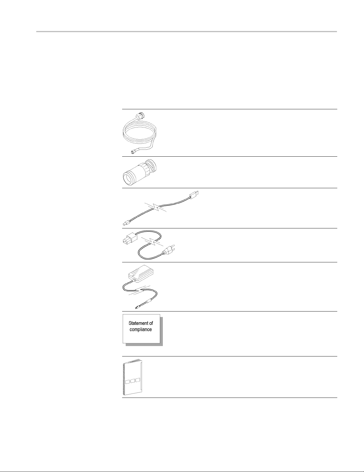
Standard accessories are listed in the table below. (See Table 2.) Order extra
standard accessories as needed.
Table 2: Sta
Accessory Descriptio
ndard accessories
1
n
50 Ω SMA-to-
connect the TekConnect probe adapter to the Real-Time
Spectrum Analyzer. T he SMA cable passes the analog
signal out
spectrum analyzer.
BNC-to-N adapter. Use the BNC-to-N adapter to connect
the TekConnect probe adapter to the Real-Time Spectrum
Analyzer RF input.
USB cabl
from a TekConnect probe adapter to the Real-Time
Spectrum Analyzer.
N cable. Use the 50 Ω SMA-to-N cable to
put from the probe adapter channel to the
e. Provides a data and communications path
Power c
Option A0 comes standard with the TekConnect probe
adapter. Other power cord options are available. (See
Table
Power supply and cable. Provides DC power to the
TekC o
Statement of compliance. Acertificate verifying that
the
procedures and work instructions. When applicable, test
equipment is traceable to known standards.
Inc
cannot be ordered.
Instruction manual. Provides instruction and information
about the TekConnect probe adapter.
Qu
TekConnect probe adapter and the Real-Time Spectrum
Analyzer.
1
See the Replaceable Parts List for Tektronix part numbers. (See Table 15 on page 28.)
ord. Provides AC power to the power supply.
4 on page 4.)
nnect probe adapter.
product is assembled and verified using established
luded with product at initial shipment. This accessory
ick reference card. Provides RF, I, and Q setups for the
RTPA2A Instruction Manual 3
Page 18
Getting Started
Options
Options that are available for the TekConnect probe adapter are listed in the two
tables that follow.
Table 3: Opt
Option Description
R3
R5
L0 English In
L5 Japanese Instruction Manual
1
See the Replaceable Parts List for Tektronix part numbers. (See Table 15 on page 28.)
ions
Repair Service 3 years (available at purchase only)
Repair Service 5 years (available at purchase only)
struction Manual
1
1
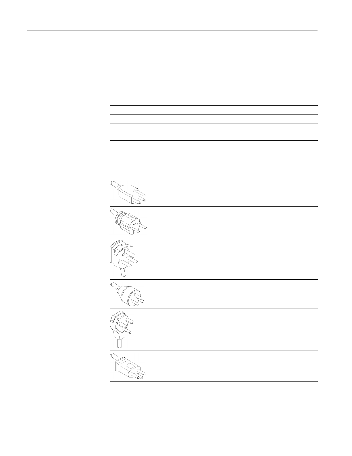
Table 4: Power cord options
Plug configuration Normal usage Option number
North America 120 V A0
(Standard)
66-00
161-00
Universal Euro A1
161-0066-09
United Kingdom A2
161-0066-10
tralia
Aus
th America 250 V
Nor
witzerland
S
A3
161-0066-13
A4
161-0104-08
A5
61-0154-00
1
4 RTPA2A Instruction Manual
Page 19

Table 4: Power cord options (cont.)
Plug configuratio n Normal usage Option number
Japan A6
161-A005-00
Getting Started
China
No power cord supplied A99
A10
161-0306-
00
RTPA2A Instruction Manual 5
Page 20

Getting Started
Installing the Probe Adapter
The TekConnect probe adapter, standard accessories, and location of the probe
inputs is shown below. (See Figure 2.)
You must allow for airflow clearance for the probe adapter. (See Table 11 on
page 19.)
Figure 2: Probe adapter inputs and outputs
6 RTPA2A Instruction Manual
Page 21

Getting Started
CONNECTIONS Table
Installing the
1. Connect the power cord.
2. Connect the power supply cable.
3. Connect the USB cable (also to the s pectrum analyzer).
4. Connect a 50 Ω SMA-to-N cable (also to the spectrum analyzer RF input).
Torque to 8 in-lb.
CAUTION. To prevent damage to the probe or spectrum analyzer, do not exceed
the voltage ratings specified on your TekConnect probe. For further probe
informat
of Probes on the Tektronix Web site.
5. Connect
All procedures in this ins truction manual match the cable configurations shown in
the CONNECTIONS table on the front of the probe adapter.
NOTE.
cable and probe connections to the spectrum analyzer. For the spectrum analyzer
to apply correct probe-related amplitude offsets, you must connect the cables as
shown under columns A and B. See the RTPA2A Real-Time Spectrum Analyzer
TekConnect Probe Adapter Setups Quick Reference for instructions on setting
up these connections.
probe adapter consists of the following steps:
ion, refer to your probe instruction manual, and if necessary, The ABC’s
a P7000 Series TekConnect probe.
The CONNECTIONS table on the front of the probe adapter recommends
RTPA2A Instruction Manual 7
Page 22

Getting Started
Installing th
e USB Cable and Power Supply Cable
When a USB cable is connected to a Tektronix Real-Time Spectrum Analyzer,
power is enabled to the probe. The USB cable must be attached for the probe
adapter and a
Use only the supplied power supply cable and power cord with the TekConnect
probe adapt
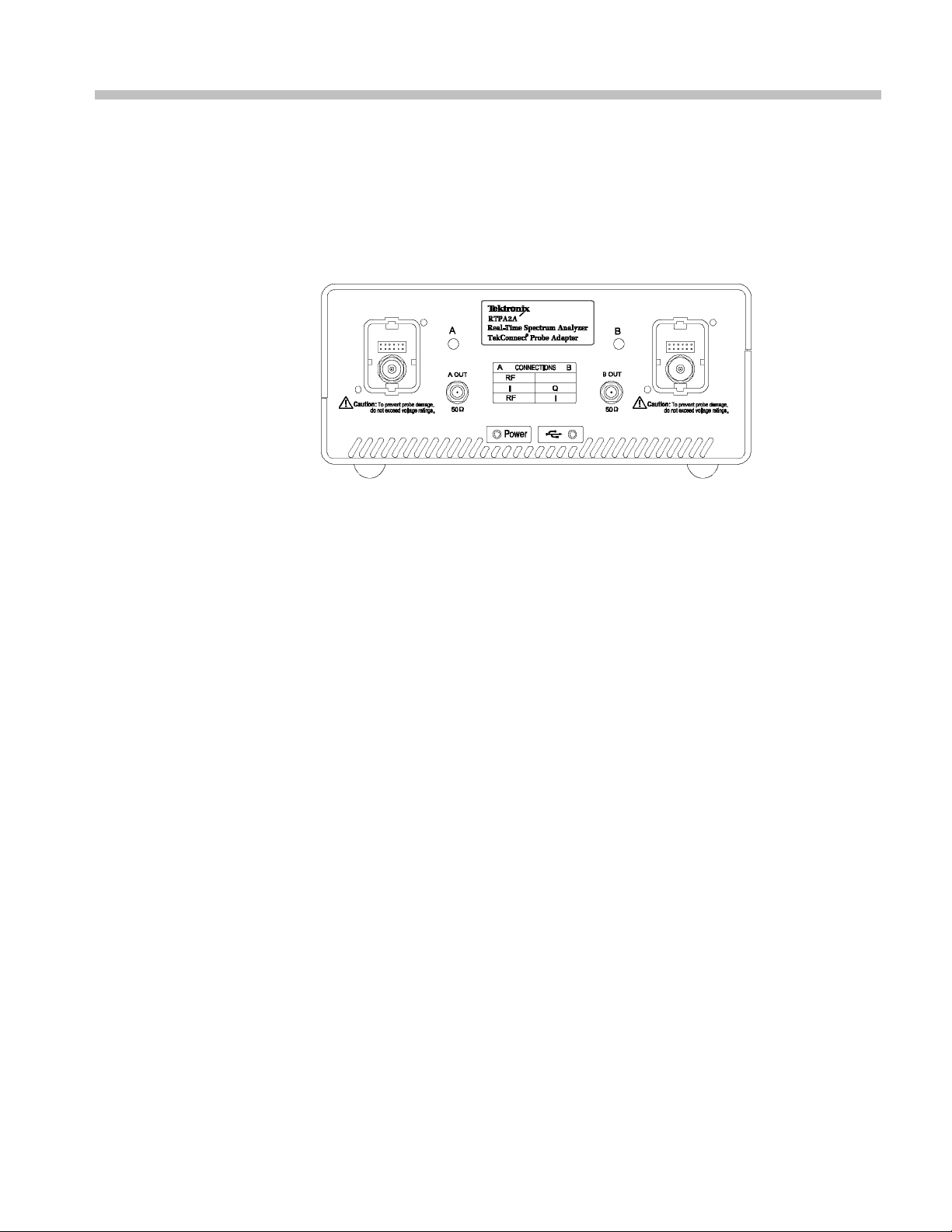
The USB and power supply connections on the back of the probe adapter are
shown belo
Spectrum Analyzer, refer to your user manual.
spectrum analyzer system to function properly.
er.
w. (See Figure 3.) To locate a USB connection on a Real-Time
Figure 3: Back panel connections
8 RTPA2A Instruction Manual
Page 23

Getting Started
Installing th
e TekConnect Probe
When the probe is connected, the probe adapter reads EEPROM information from
the probe, identifying the device and allowing the appropriate power s upplies
to be powered
NOTE. It is not necessary to power off the probe adapter when removing or
installing a TekConnect probe.
The TekConnect interface features a spring-loaded latch that provides audible and
tactile confirmation that a reliable connection has been made to the probe adapter.
Slide the probe into the TekConnect receptacle on the probe adapter. The probe
snaps into the receptacle when fully engaged. (See Figure 4.)
To release the probe from the probe adapter, grasp the compensation box, press
the latch button, and pull out the probe.
on.
Figure 4: Installing TekConnect probes
NOTE. Use the integral thumb screw (on probe models that have the option), to
secure the probe to the adapter.
RTPA2A Instruction Manual 9
Page 24

Getting Started
Performing a F
unctional Check
To verify that the TekConnect probe adapter is functioning properly, perform
the following procedure. Refer to the table below for a list of recommended
equipment. (
Table 5: Recommended equipment for functional check
Item description Recommended exam ple
Real-Time Spectrum Analyzer Tektronix RSA2200A, RSA3300A,
USB cable
Power s upply and cable
50 Ω SMA-to-N cable
TekConnect probe Tektronix P7000 Series
Probe tip adapter Attaching the probe tip will leave your hands
50 Ω (M-to-M) RF coaxial cable
BNC (F-to-F) adapter
T-BNC (M-to-two F) connector
50 Ω (BNC-type) termination
1
2
1
Included with the RTPA2A TekConnect probe adapter.
Nine-digit part numbers (XXX-XXXX-XX) are Tektronix part numbers.
See Table 5.)
1
1
RSA3408A, or WCA200A Series (See
page 1, Real-Time Spectrum Analyzer
Software Compatibility.)
174-4401-XX
119-7017-XX
174-5218-XX
2
2
2
free to perform the functional check.
Use the standard accessories recommended
in the functional check for your TekConnect
probe to attach the probe tip to a connector.
012-0057-XX
103-0028-XX
103-0030-XX
011-0049-XX
2
2
2
or equivalent
2
or equivalent
To verify the functionality of Channel A, perform the following tasks:
1. Set up the spectrum analyzer:
ower on and wait for the boot-up process to complete, if necessary.
a.P
b. Preset the factory defaults. For example, RSA2203A - Press the System
ey, and then press the Reset All to Factory Defaults side key.
k
c. Set the center frequency to 10 MHz.
d. Set the span to 1 MHz.
2. Connect the probe adapter as shown. (See Figure 5.) If necessary, refer to
Installing the Probe Adapter for more information. (See page 6, Installing the
Probe Adapter.)
10 RTPA2A Instruction M anual
Page 25

Getting Started
Figure
3. On the
NOTE. The probe adapter automatically powers off if the fan fails.
5: Connecting the RTPA2A components
probe adapter, visually check that the LEDs are lighted green. The
status LEDs on the probe adapter are lighted only when a probe is attached.
The LED locations are shown. (See Figure 6.)
If they are not lighted green, see the Troubleshooting section. (See page 23,
Troubleshooting.)
RTPA2A Instruction Manual 11
Page 26
Getting Started
Figure 6: Check for lighted LEDs
4. Connect the spectrum analyzer:
a. Attach o
spectrum analyzer.
b. Attach t
(See Figure 7.)
c. Attach
d. Attach the 50 Ω (BNC type) termination to an open end of the T-BNC
conne
ne end of a 50 Ω cable to the REF OUT connector on the
he other end of a 50 Ω cable to a BNC (F-to-F) barrel connector.
the BNC (F-to-F) barrel connector to the center T-BNC connector.
ctor.
12 RTPA2A Instruction M anual
Page 27
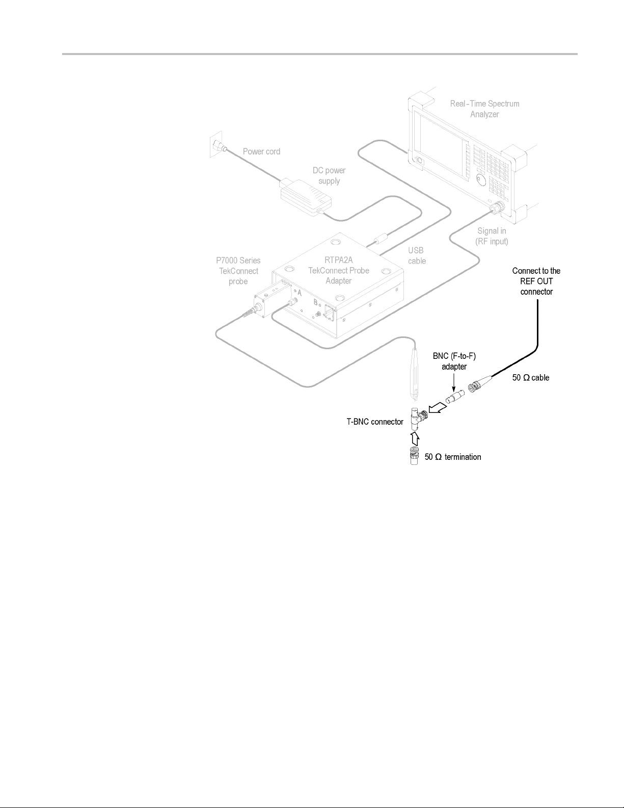
Getting Started
Figure 7: Equipment setup with Real-Time Spectrum Analyzer
5. Install a probe-tip adapter on the probe (optional). This leaves your hands free
to complete the rest of the functional check.
6. Connect the probe tip to the open end of the T-BNC connector.
The spectrum analyzer displays an amplitude signal (0 dBm ±5 dB) as shown.
(See Figure 8.)
RTPA2A Instruction Manual 13
Page 28

Getting Started
Figure 8: Amplitude signal
To verify the functionality of Channel B, perform the following tasks:
1. Move the probe from Channel A to Channel B.
2. Move the SMA cable from A OUT to B OUT.
NOTE. The spectrum analyzer will adjust the RF amplitude offset for Channel
A only. To correct the amplitude for Channel B, refer to the table below. (See
Table 6
.) For example, if you are using a 5X probe on Channel B, manually apply
an amplitude offset of –14 dB.
6: Probe amplitude offset for Channel B
Table
attenuation
Probe
2.5X –8 dB
5X –14 dB
6.25X –16 dB
10X –20
12.5X –22 dB
25X –28 dB
Amplitude offset
dB
14 RTPA2A Instruction M anual
Page 29

Operating Basics
This section contains information you need to operate the TekConnect probe
adapter.
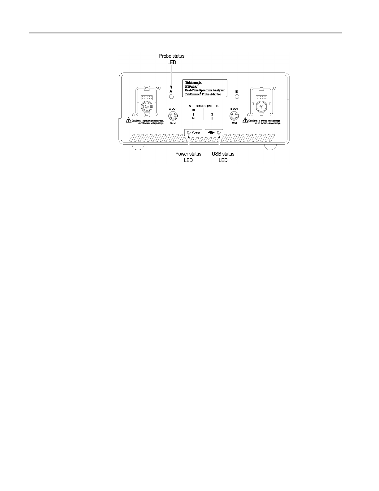
Understanding the Controls
The front panel on the TekConnect probe adapter has an LED for the status
of power, U
explanations. (See page 23, Troubleshooting.)
SB, and each probe connection. See the following LED status
Power Status
USB Status
Figure 9: Location o f status LEDs
The table below describes LED operation when power is on.
Table 7: Power status LED
LED Indicates
Solid green
Off
The table below describes LED operation when a USB cable is attached.
Table 8: USB status LED
LED Indicates
Solid green The USB host is detected and the spectrum
Proper power is applied
The probe adapter is not receiving power
analyzer is supported
RTPA2A Instruction Manual 15
Page 30

Operating Basics
Table 8: USB status LED (cont.)
LED Indicates
Flashes green
Off The USB host was not detected; recheck the
The USB host is detected, but the spectrum
analyzer is not supported
USB cable
Probe Status
The table below describes LED operation when a TekConnect probe is attached.
Table 9: Probe status LED
LED Indicates
Solid green
Solid red
Off
A suppor
An unsup
attached.
No powe
TekCo
ted probe is attached
ported or unrecognized probe is
r to the probe adapter
nnect receptacle did not detect a probe
NOTE. The Power and USB LEDs m ust both be solid green for the probe status
LEDs to operate.
16 RTPA2A Instruction M anual
Page 31

Reference
This section contains information you may need to t ake measurements or to avoid
damaging the RTPA2A product.
Avoiding Damage from Electrostatic Discharge or Overvoltage
Circuitry in the TekConnect probe adapter and probe is very susceptible to
damage fro
the system only in a static-controlled environment. Be sure to discharge to ground
any electrostatic charge that may be present on the center and outer connectors
of cables before attaching the cables to the system. Be sure to operate the
TekConnect probe adapter and probe only where DC voltage levels are within the
probe limits. Refer to the probe specifications in your probe instruction manual.
m electrostatic discharge or from overdrive signals. Be sure to operate
RTPA2A Instruction Manual 17
Page 32

Reference
18 RTPA2A Instruction M anual
Page 33

Specifications
This section lists the electrical, environmental, and physical characteristics of
the RTPA2A product.
Typical specifications are provided for your convenience and are not guaranteed.
The electrical characteristics listed below are valid when the RTPA2A product
operates within the environmental conditions listed in the table. (See Table 11.)
Table 10: Electrical characteristics
Characteristic Description
Output impedance, nominal 50 Ω
Frequency range2,typical
Insertion loss, typical
Without RF cable attached
With 1 meter cable (SMA-to-N)
174-5218-XX
Return loss, typical
Without RF cable attached
With 1 meter cable (SMA-to-N)
174-5218-XX
Electrical delay, nominal
Without RF cable attached 470 ps
With 1 meter male-to-male cable 4.62 ns
1
Provided by the spectrum analyzer input.
2
Provided by the RTPA2A product only.
1
DC to >18 GHz
DC to 10 GHz: <0.3 dB
(See Figure 10 on page 20.)
DC to 18 GHz: <0.5 dB
DC to 10 GHz: <1.2 dB
DC to 18 GHz: <2 dB
DC to 5 GHz: >25 dB
DC to 10 GHz: >20 dB
(See Figure 11 on page 21.)
DC to 18 GHz: >15 dB
DC to 5 GHz: >25 dB
DC to 10 GHz: >20 dB
DC to 18 GHz: >15 dB
Table 11: Environmental characteristics
Characteristic Description
Temperature range
Operating 10°Cto40°C(50°Fto104°F)
Nonoperating
Humidity
Operating 20 to 80% RH, noncondensing
Nonoperating
–20 °C to +60 °C (–68 °F to 140 °F)
5 to 90% RH, noncondensing
RTPA2A Instruction Manual 19
Page 34

Specifications
Table 11: Environmental characteristics (cont.)
Characteristic Description
Altitude
Operating 3,048 m (10,000 ft)
Nonoperating
Mechanical shock
Required airflow clearance (front and back) 2 in ( 5.08 cm)
12,190 m (40,000 ft)
50 g half-sine: 11 ms
Table 12
Characteristic Description
Weight
Dimens
Cabl
1
: Physical characteristics
1
ions
e length, nominal
Does not include accessories and shipping container.
1.07 kg (2.36 lbs)
Height: 110 mm (4.250 in)
Width: 70 mm (2.750 in)
: 42 mm (1.625 in)
Depth
.28 ft)
1m(3
The graphs of insertion loss and return loss are as follows:
Figure 10: Insertion loss
20 RTPA2A Instruction M anual
Page 35

Figure 11: Return loss
Specifications
RTPA2A Instruction Manual 21
Page 36

Specifications
22 RTPA2A Instruction M anual
Page 37

Maintenance
This section contains information on troubleshooting and how to clean and
maintain your equipment.
Inspecting and Cleaning
Remove accumulated loose dust from the probe adapter with a soft cloth or brush.
Remaining dirt may be removed with a soft cloth dampened with isopropyl
alcohol.
Do not immerse any equipment in cleaning solutions or use abrasive cleaners.
CAUTION. To prevent damage, avoid using cleaning materials that contain
acetone,
Troubleshooting
If you encounter problems installing or operating the probe adapter, try the
troubleshooting procedures before returning the probe adapter for service. (See
page 23, Troubleshooting.)
benzene, toluene, xylene, or similar solvents.
NOTE. If problems occur with your TekConnect probe adapter, the Technical
rt Center may need the firmware version of your probe adapter to isolate
Suppo
the symptoms to a specific cause. The firmware version number is located on the
back of the TekConnect probe adapter.
Table 13: Probe Adapter LEDs
LEDs
Power USB Probe Problem Check
on on green
off off off Power status LED remains off
on
on
off off USB status LED remains off USB connections on the probe adapter
flashing off USB status LED flashes If the spectrum analyzer software
None (probe adapter performing correctly)
—
Power c ord connection.
and spectrum analyzer.
needs to be upgraded. Refer to
Real-Time Spectrum Analyzer Software
Compatibility for more information. (See
page 1, Real-Time Spectrum Analyzer
Software C ompatibility .)
RTPA2A Instruction Manual 23
Page 38

Maintenance
Table 13: Probe Adapter LEDs (cont.)
LEDs
Power USB Probe Problem Check
on on
on on
on on green
off
red Probe status LED is red
Probe status LED on the probe adapter
remains off, and the fan is not rotating
Probe status LED on the probe adapter
remains off, and the fan is rotating
No Signal Detected (from the connected
TekConnect probe)
An internal fault has been detected. Send
the probe adapter for service.
If the probe status LED lights when the
probe is connected to the other probe
adapter channel, send the probe adapter
for service.
If the probe functions incorrectly in a
TekConnect oscilloscope, send the probe
for service.
If the probe status LED on the probe
adapter does not light in either channel,
but the probe functions in a TekConnect
scope, send the probe adapter for service.
Incompatible probe (See Table 1 on
page 2.)
The 50 Ω cable connection(s) between
the spectrum analyzer and the probe
adapter.
Product Requires Service
The following conditions indicate an internal failure. See the copyright page at
the front of the manual for information on contacting Tektronix for service.
No probe-adapter LEDs active at power on.
Probe status LEDs are inactive on one channel, but are active on the other
channel of the TekConnect probe adapter.
Probe status LED response is inconsistent when connecting the same probe
alternately to each channel of the TekConnect probe adapter.
USB status LED flashes even when attached to a valid Real-Time Spectrum
Analyzer.
Neither probe status LED lights when working probes are attached.
Power status LED is lighted, but the fan is not rotating.
24 RTPA2A Instruction M anual
Page 39

Maintenance
Repackaging f
or Shipment
If the original packaging is unfit for use or not available, use the following
packaging guidelines:
1. Use a corrugated cardboard shipping carton having inside dimensions at least
2. Place the probe adapter into an antistatic bag or wrap to protect it from
3. Place the probe adapter into the box and stabilize it with light packing material.
4. Seal the carton with shipping tape.
one inch greater than the probe dimensions. The box must have a carton
test streng
dampness.
th of at least 200 pounds.
RTPA2A Instruction Manual 25
Page 40

Maintenance
26 RTPA2A Instruction M anual
Page 41

Replaceable Parts
This section contains a list of the replaceable parts for the RTPA2A TekConnect
probe adapter. Use this list to identify and order replacement parts.
Parts Ordering Information
Replacement parts are available through your local Tektronix field office or
representative.
Changes to Tektronix products are sometimes made to accommodate improved
components as they become available and to give you the benefit of the latest
improvements. Therefore, when ordering parts, it is important to include the
followin
If you order a part that has been replaced with a different or improved part, your
local Tektronix field office or representative will contact you concerning any
change in part number.
ginformationinyourorder:
Part number
Instrument type or model number
Instrument serial number
Instrument modification n umber, if applicable
Using the Replaceable Parts List
This section contains a list of the mechanical and or electrical components that are
replaceable. Use this list to identify and order replacement parts. The following
table describes each column in the parts list.
ble 14: Parts list column descriptions
Ta
Column Column name Description
1
2 Tektronix part
3 and 4
5
6
Figure & index
number
number
Serial number Column three indicates the serial number at which the part was first effective. Column four
Qty This indicates the quantity of parts used.
Name &
description
Items in this section are referenced by figure and index numbers to the exploded view
illustrations that follow.
Use this part number when ordering replacement parts from Tektronix.
indicates the serial number at which the part was discontinued. No entry indicates the part is
good for all serial numbers.
An item name is separated from the description by a colon (:). B ecause of space limitations,
an item name may sometimes appear as incomplete. Use the U.S. Federal Catalog handbook
H6-1 for further item name identification.
RTPA2A Instruction Manual 27
Page 42

Replaceable Parts
Abbreviations
Abbreviations
conform to American National Standard ANSI Y1.1-1972.
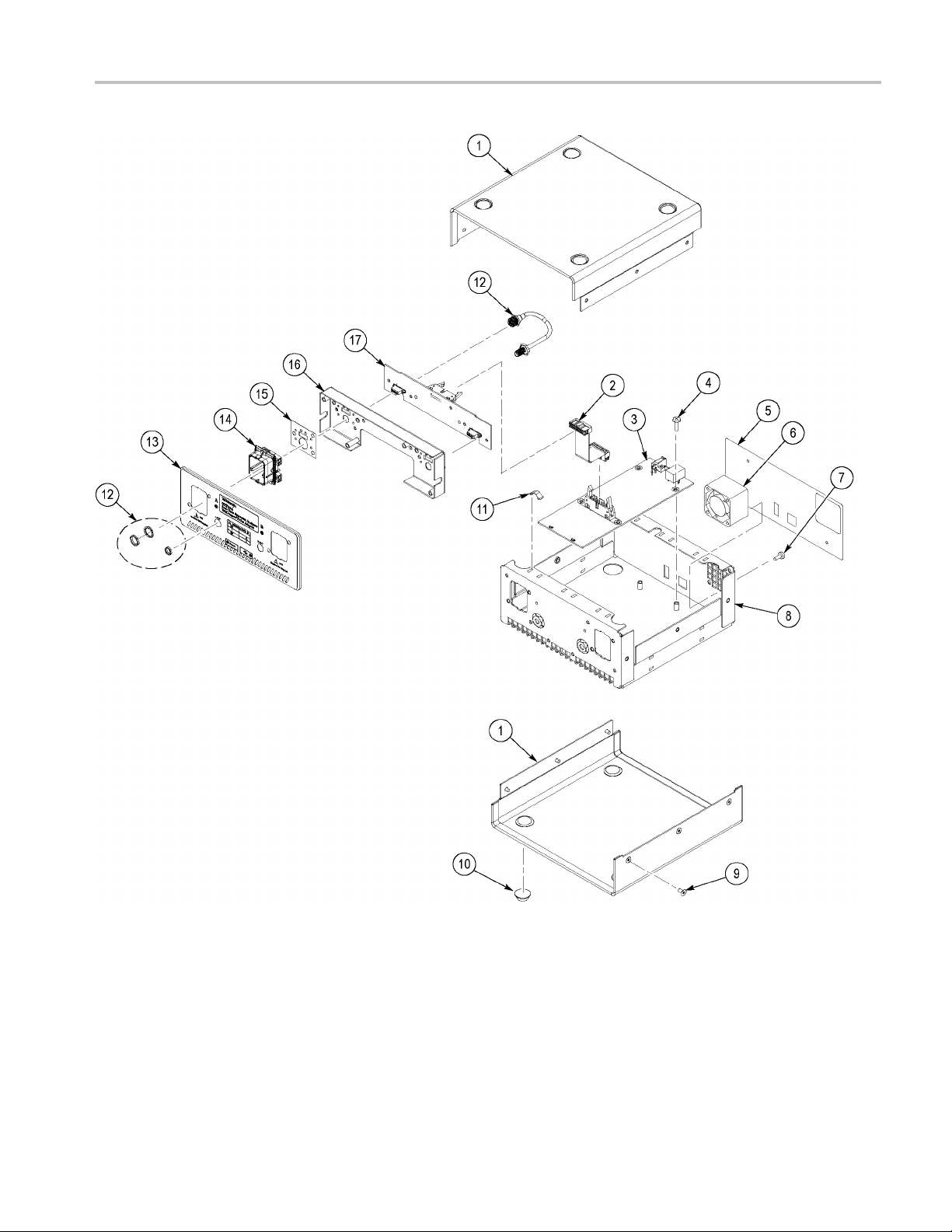
Table 15: Replaceable parts list
Fig. &
index
number
12-1 200-4827-XX 1
12-2 174-5189-XX 1
12-3 671-6079-XX 1
12-4 211-0722-XX 1
12-5 335-1350-XX 1
12-6 119-6617-XX 1
12-7
12-8 441-2442-XX 1
12-9 211-0734-XX 1
12-10 348-0430-XX 1
12-11 131-6417-XX 1
12-12 174-4856-XX 1
12-13 386-7448-XX 1
12-14 426-2625-XX 1
12-15 335-0428-XX 1
12-16 407-5087-XX 1
12-17 671-6176-XX 1
Tektronix part
number
211-0208-XX 1
220-0221-XX 1
071-1766-XX 1
071-1767-XX 1
071-1776-XX 1
174-5218-XX 1
103-0058-XX 1
174-4401-XX 1
119-7017-XX 1
161-0066-00 1 A0
Serial no.
effective
Serial no.
discont’d Qty Name & description
Standard Accessories
COVER; EXTERIOR,AL;SAFETY CONTROLLED
CABLE ASSEMBLY;2X8 .100 CENTER, .050 RIBBON, 8.00 LONG
CIRCUIT BD ASSY;USB;389378500,WIRED
SCREW,MACHINE; 6-32 X 0.250,PNH,STL,CDPL,T-15 TORX DR
MARKER,IDENT; LABEL, REAR PANEL; SAFETY CONTROLLED
FAN ASSEMBLY; DC,12V;0.045A,TACH OUTPUT,4100 RPM,5
CFM,20DBA,40MM X 40MM X 28MM;6 IN,3 LEAD, WITH CONN &
HOUSING,SAFETY CONTROLLED
SCREW,MACHINE; 4-40 X 1.625,FLH,100 DEG,STL CD PL,POZ
NUT ASSY; 4-40 X .250,HEX,LOCK WASHER
CHASSIS ASSY; MAIN
SCREW,MACHINE; 6-32 X 0.25O,FLH100,STL,CDPL,T-10 TORX DR
BUMPER,PLASTIC; POLYURETHANE,BLACK
CONTACT,ELEC; GROUNDING,0.600 L X 0.250 W X 0.220
D,ELECTROLESS NICKEL PLATE
CA,ASSY;SP,ELEC,SEMI-RIGID COAX, 0.141 OD
PLATE,MOUNTING;AL,SELLWOOD
MODULAR KIT; RECEPTACLE; PROBE ASSEMBLY, LATCHING,
SAFETY CONTROLLED
MARKER,IDENT; LABEL,COSMETIC,RECEPTACLE
BOTTOM,BLACK,LEXAN,W/PSA,SAFETY CONTROLLED
BRACKET ASSY, TEKCONNECT BUCKET MOUNT
CIRCUIT BD ASSY;TEKCONNECT INTERFACE CONTROL,W/V1.2
SW APPLICATION
MANUAL,INSTRUCTION; RTPA2A REAL-TIME SPECTRUM
ANALYZER TEKCONNECT PROBE ADAPTER,ENGLISH (standard
accessory, if you ordered Option L0)
CARD, QUICK REFERENCE;RTPA2A REAL-TIME SPECTRUM
ANALYZER TEKCONNECT PROBE ADAPTER
MANUAL,INSTRUCTION;RTPA2A REAL-TIME SPECTRUM
ANALYZER TEKCONNECT PROBE ADAPTER,JAPANESE,PAPER
(standard accessory, i f you ordered Option L5)
CABLE ASSY;MALE N CONNECTOR TO SMA
ADAPTER,CONN; N FEMALE TO BNC MALE
CABLE ASSY,I/O; USB, 26 AWG, 3 FT, A TO B, MALE, BLACK
POWER SUPPLY; EXTERNAL, DESKTOP (W/SPECIAL MOLEX
OUTPUT CONNECTOR) ; 50W, 12VDC 4.1A OUT, 90 - 254VAC 47 - 63
HZ IN; 78% EFF, UL, CSA, PSE, CCC ,SAFETY CONTROLLED
CABLE ASSY,PWR; 3,18 AWG,250V/10A,98.0 L,STR,IEC320,RCPT X
NEMA 5-15P,US,SAFETY CONTROLLED
28 RTPA2A Instruction M anual
Page 43
Replaceable Parts
Figure 12: Exploded view
RTPA2A Instruction Manual 29
Page 44

Replaceable Parts
Table 16: Optio
Tektronix
part number
161-0066-09 A1
161-0066-10 A2
161-0066-1
161-0104-08 A4
161-0154-00 A5
161-030
161-A005-00 A6
6-00
nal accessories
3
Option
number Name & description
A3
A10
CABLE ASSY,PWR; 3,0.75MM SQ,250V/10A,99.0
L,STR,IEC32
CABLE ASSY,
13A,FUSED UK PLUG(13A FUSE),UNITED KINGDOM,SAFETY CONTROLLED
CABLE ASSY,PWR; 3,1.0 MM SQ,250V/10A,2.5
METER,STR,IEC320,RCPT,AUSTRALIA,SAFETY CONTROLLED
CABLE ASSY,PWR; 3,18 AWG,250/10A,98.0 L,RTANG,IEC320,RCPT X STR,NEMA
6-15P,US
CA ASSY,P
METER,STR,IEC320,RCPT,SWISS,SAFETY CONTROLLED
CABLE ASSY,PWR; 3,1.0MM SQ,250V/10A,2.5 METER,RTANG,IEC320,RCPT,3C
CERTIFICATION,CHINA;SAFETY CONTROLLED
CABLE ASSY,PWR; RT ANGLE, JAPANESE T MARK,SAFETY CONTROLLED
0,RCPT,EUROPEAN,SAFETY CONTROLLED
PWR; 3,1.0 MM SQ,250V/10A,2.5 METER,STR,IEC320,RCPT X
,SAFETY CONTROLLED
WR; 3,1.0MM SQ,250V/10A,2.5
30 RTPA2A Instruction M anual
 Loading...