

Page 1

xx
Tektronix PPG4001
ZZZ
PatternPro® Programmable Pattern Generator
User Manual
*P077108900*
077-1089-00
Page 2

Page 3

xx
Tektronix PPG4001
ZZZ
PatternPro® Programmable Pattern Generator
User Manual
www.tektronix.com
077-1089-00
Page 4

Copyright © Tektronix. All rights reserved. Licensed software products are owned by Tektronix or its subsidiaries
or suppliers, and are protected by national copyright laws and international treaty provisions.
Tektronix products are covered by U.S. and foreign patents, issued and pending. Information in this publication
supersedes that in all previously published material. Specifications and price change privileges reserved.
TEKTRONIX and TEK are registered trademarks of Tektronix, Inc.
Contacting Tektronix
Tektronix, Inc.
14150 SW Karl Braun Drive
P.O. B o x 5 0 0
Beaverto
USA
For product information, sales, service, and technical support:
n, OR 97077
In North America, call 1-800-833-9200.
Worldwide, visit www.tektronix.com to find contacts in your area.
Page 5

Warranty
Tektronix warrants that this product will be free from defects in materials and workmanship for a period of one (1)
year from the date of shipment. If any such product proves defective during this warranty period, Tektronix, at its
option, either will repair the defective product without charge for parts and labor, or will provide a replacement
in exchange for the defective product. Parts, modules and replacem ent products used by Tektronix for warranty
work may be n
the property of Tektronix.
ew or reconditioned to like new performance. All replaced parts, modules and products become
In order to o
the warranty period and make suitable arrangements for the performance of service. Customer shall be responsible
for packaging and shipping the defective product to the service center designated by Tektronix, w ith shipping
charges prepaid. Tektronix shall pay for the return of the product to Customer if the shipment is to a location within
the country in which the Tektronix service center is located. Customer shall be responsible for paying all shipping
charges, duties, taxes, and any other charges for products returned to any other locations.
This warranty shall not apply to any defect, failure or damage caused by improper use or improper or inadequate
maintenance and care. Tektronix shall not be obligated to furnish service under this warranty a) to repair damage
result
b) to repair damage resulting from imp roper use or connection to incompatible equipment; c) to repair any damage
or malfunction caused by the use of non-Tektronix supplies; or d) to service a product that has b een modified or
integrated with other products when the effect of such modification or integration increases the time or difficulty
of servicing the product.
THIS WARRANTY IS GIVEN BY TEKTRONIX WITH RESPECT TO THE PRODUCT IN LIEU OF ANY
OTHER WARRANTIES, EXPRESS OR IMPLIED . TEKTRONIX AND ITS VENDORS DISCLAIM ANY
IMPLIED WARRANTIES OF MERCHANTABILITY OR FITNESS FOR A PARTICULAR PURPOSE.
TRONIX' RESPONSIBILITY TO REPAIR OR REPLACE DEFECTIVE PRODU CTS IS THE SOLE
TEK
AND EXCLUSIVE REMEDY PROVIDED TO THE CUSTOMER FOR BREACH OF THIS WARRANTY.
TEKTRONIX AND ITS VENDORS WIL L NOT BE LIABLE FOR ANY INDIRECT, SPECIAL, IN CIDEN TAL,
OR CONSEQUENTIAL DAMAGES IRRESPECTIVE OF W HET HER TEKTRONIX OR THE VENDOR H AS
ADVANCE NOTICE OF THE POSSIBILITY OF SUCH DAMAGES.
[W2 – 15AUG04]
btain service under this warranty, Customer must notify Tektronix of the defect before the expiration of
ing from attempts by personnel other th an Tektronix representatives to install, repair or service the product;
Page 6

Page 7

Table of Contents
Important safety information ..................... ................................ ................................. v
General safety summary ...................................................................................... v
Service safety summary ................................ .................................. ................... vii
Terms in this manual ..................... .................................. ................................. vii
Symbols and terms on the product ......................................................................... viii
Preface .............................................................................................................. ix
Features ...... ................................ .................................. ................................ ix
Documentation ................................................................................................. x
Getting started.... . . . ..... . ..... . ..... . . ... . . . ..... . ..... . ..... . . ..... . ..... . ..... . . ... . . . ..... . ..... . .... . . .... . . ... 1
Installation............................... .................................. ................................ ..... 1
Controls and connectors ........................................................................................... 4
Functional verification ............................................................................................. 6
Instrument setup ............................................................................................... 6
Power on and verify instrument operation ... .................................. ............................. 6
Verify the eye diagram ............... .................................. .................................. ..... 8
Check other settings . . ..... . ..... . ..... . .... . . .... . . .... . . .... . . .... . . .... . . .... . . .... . . .... . . .... . . .... . . .... . 9
Data and clock output instructions...... .................................. .................................. . 9
Input and output descriptions..................................................................................... 11
Overview ............ .................................. .................................. ...................... 11
Data outputs . .................................. ................................ ................................ 12
Graphical user interface (GUI) touch screen ......... .................................. ........................ 13
Jitter insertion (optional feature) ..... . ..... . ..... . ..... . ..... . ..... . ..... . ..... . ..... . ..... . ..... . ..... . ..... . ... 15
Jitter sources. . ..... . ..... . ..... . ..... . ... . . ..... . ..... . ..... . ..... . ..... . ... . . . .... . . .... . ..... . ..... . ..... . ... 15
Specifications .. ................................ .................................. .................................. 17
Data outputs . .................................. ................................ ................................ 17
Clock outputs........................ .................................. ................................ ........ 17
Data patterns .................................................................................................. 18
Jitter insertion . . . .... . . .... . . .... . . .... . . .... . . ... . . . .... . . .... . . .... . . .... . . .... . . ... . . . .... . . .... . . .... . . .... 19
Trigger system ................................................................................................ 20
Clock inputs ................................................................................................... 20
Reference clock ............................................................................................... 21
Control interfaces ....................... .................................. .................................. .. 21
Physical characteristics................................... .................................. .................. 22
Remote programming....... .................................. ................................ .................... 23
USB interface ................................................................................................. 23
Command information ................. ................................ .................................. .... 23
Common commands............... .................................. .................................. ............ 24
Summary....................................................................................................... 24
Reference ...................................................................................................... 24
PPG4001 Pattern Generator User Manual i
Page 8

Table of Contents
Regular comman
Summary....................................................................................................... 25
Reference ................... .................................. ................................ ...................... 29
:DIGital:PATTern:LENGth .................................................................................. 29
:DIGital:PATTern:TYPE ............. .................................. .................................. .... 29
:DIGital:PATTern:PLENgth ............. .................................. .................................. 30
:DIGital:PATTern:DATA..................... .................................. .............................. 31
:DIGital:PATTern:HDATa ................................................................................... 32
:DIGital:PATTern:SERRor....................................... .................................. .......... 33
:DIGital:PATTern:ERATe.... .................................. ................................ .............. 33
:DIGital:PATTern:ERATe:STATe ........................................................................... 33
:DIGital:PATTern:BSHift .................................................................................... 34
:DIGital:SIGNal[:POS|:NEG]:CROSsover:[VALue]..................................................... 34
:MMEMory:STORe:PDATa................................................................................. 35
:MMEMory:STORe:STATe ................................................................................. 35
:MMEMory:LOAD:PDATa ................... ................................ .............................. 35
:MMEMory:LOAD:STATe .................................................................................. 36
:MMEMory:MOVE:PDATa ....................... .................................. ........................ 36
:MMEMory:MOVE:STATe.................................................................................. 36
:MMEMory:DELete:PDATa............... .................................. ................................ 37
:MMEMory:DELete:STATe ............... .................................. ................................ 37
:MMEMory:CATalog:PDATa? ............................ .................................. ................ 37
:MMEMory:CATalog:STATe?................... .................................. .......................... 38
:OUTPut0:SOURce........................................................................................... 38
:OUTPut0:DIVider ........................................................................................... 38
:OUTPut:POLarity.................................... .................................. ...................... 39
:OUTPut[:STATe]..................................... ................................ ........................ 39
:OUTPut:CLOCk:DIVider................................................................................... 39
:SENSe:ROSCillator:SOURce ..... . ..... . ..... . ..... . ..... . ..... . ..... . ..... . ..... . ..... . ..... . ..... . ..... . 40
[:SOURce]:FREQuency[:CW|:FIXed] . .................................. .................................. 40
[:SOURce]:PM[:HF][:STATe]............................................................................... 40
[:SOURce]:PM[:HF]:INTernal1[:DEViation] ............................................................. 41
[:SOURce]:PM[:HF]:INTernal1:FREQuency ............................... .............................. 41
[:SOURce]:PM[:HF]:INTernal1:STATe.................................................................... 41
[:SOURce]:PM[:HF]:INTernal2[:DEViation] ............................................................. 42
[:SOURce]:PM[:HF]:INTernal2:STATe.................................................................... 42
[:SOURce]:PM[:HF]:INTernal4:CALibration............................. ................................ 42
[:SOURce]:PM[:HF]:INTernal4[:DEViation] ............................................................. 43
[:SOURce]:PM[:HF]:INTernal4:FILTer................................ .................................. .. 43
[:SOURce]:PM[:HF]:INTernal4:FREQuency ............................... .............................. 43
[:SOURce]:PM[:HF]:INTernal4:PLENgth......................................... ........................ 44
ds ...... .................................. ................................ ........................ 25
ii PPG4001 Pattern Generator User Manual
Page 9

Table of Contents
[:SOURce]:PM[
[:SOURce]:PM:LF[:INTernal3][:DEViation] ............................................................. 44
[:SOURce]:PM:LF[:INTernal3]:FREQuency ............................................................. 45
[:SOURce]:PM:LF[:INTernal3]:STATe .............. .................................. .................... 45
[:SOURce]:VOLTage[:POS|:NEG][:LEVel][:IMMediate]:[:AMPLitude] ..................... ........ 45
[:SOURce]:VOLTage[:POS|:NEG][:LEVel][:IMMediate]:OFFSet ... . . ..... . ..... . ... . . . .... . ..... . ... 46
[:SOURce]:
[:SOURce]:VOLTage[:LEVel][:IMMediate]:LINK..................................... .................. 46
:SYSTem:ERRor[:NEXT]?...... ................................ .................................. .......... 47
:TRIGger:SOURce ..................... .................................. .................................. .. 47
:TRIGger:LOCK.............................................................................................. 48
User service ........................................................................................................ 49
Service
General care ..... .................................. .................................. .......................... 49
Preventive maintenance.................. .................................. .................................. 50
Fuse replacement ................. .................................. ................................ .......... 51
Repack the instrument for shipment.............. ................................ .......................... 51
Compliance information .......................................................................................... 53
EMC c
Safety compliance ............................................................................................ 54
Environmental considerations ............................................................................... 56
Index
offerings.................. ................................ .................................. .......... 49
ompliance . ................................ .................................. .......................... 53
:HF]:INTernal4:STATe.......................... .................................. ........ 44
VOLTage[:POS|:NEG][:LEVel][:IMMediate]:TERMination.............................. 46
PPG4001 Pattern Generator User Manual iii
Page 10

Table of Contents
List of Figure
Figure 1: Front panel controls and connectors .................................................................. 4
Figure 2: Re
Figure 3: Verification setup........................................................................................ 6
Figure 4: Clock (top) and data (bottom) waveforms ........................................................... 8
Figure 5: Typical eye diagram example......................... .................................. ............... 9
Figure 6: Block diagram.............................. .................................. .......................... 12
Figure 7: GUI Main menu........................................................................................ 13
ar panel connectors .................................................................................. 5
List of Tables
Table i
Table 1: Power requirements...................................................................................... 2
Table 2: Maximum operating environmental considerations .................................................. 3
Table 3: Front panel controls and connectors ................................................................... 4
Table 4: Rear panel connectors ...... .................................. ................................ ........... 5
Table 5: GUI menu parameter locations .. ................................ .................................. .... 13
: PPG4001 Product options................................................................................ x
s
iv PPG4001 Pattern Generator User Manual
Page 11

Important safety information
This manual contains information and warnings that must be followed by the user
for safe operation and to keep the product in a safe condition.
To safely perform service on this product, additional information is provided at
the end of this section. (See page vii, Service safety summary.)
General safety summary
Use the product only as specified. Review the following safety precautions to
avoid inj
Carefully read all instructions. Retain these instructions for future reference.
ury and prevent damage to this product or any products connected to it.
oavoidfire or personal
T
injury
Comply wi
For correct and safe operation of the product, it is essential that you follow
general
in this manual.
The pro
Only qualified personnel who are aware of the hazards involved should remove
the co
Before use, always check the product with a known source to be sure it is
oper
This product is not intended for detection of hazardous voltages.
Use personal protective equipment to prevent shock and arc blast injury where
hazardous live conductors are exposed.
When incorporating this equipment into a system, the s afety of that syste m is the
responsibility of the assembler of the system.
e proper power cord. Use only the power cord specified for this product and
Us
certified for the country of use.
th local and national sa fety codes.
ly accepted safety procedures in addition to the safety precautions specified
duct is designed to be used by trained personnel only.
ver for repair, maintenance, or adjustment.
ating correctly.
o not use the provided power cord for other products.
D
Ground the product. This product is grounded through the grounding conductor
of the power cord. To avoid electric shock, the grounding conductor must be
connected to earth ground. Before making connections to the input or output
terminals of the product, make sure that the product is properly grounded.
Do not disable the power cord grounding connection.
PPG4001 Pattern Generator User Manual v
Page 12

Important safety information
Power disconne
source. See instructions for the location. Do not position the equipment so that
it is difficult to operate the power cord; it must remain accessible to the user at
all times to allow for quick disconnection if needed.
Observe all terminal ratings. To avoid fire or shock hazard, observe all ratings
and markings on the product. Consult the product manual for further ratings
information before making connections to the product.
Do not apply a potential to any terminal, including the common terminal, that
exceeds the maximum rating of that terminal.
The measuring terminals on this product are not rated for connection to mains or
Category II, III, or IV circuits.
Do not operate without covers. Do not operate this product with covers or panels
removed, or with the case open. Hazardous voltage exposure is possible.
Avoid exposed circuitry. Do not touch exposed connections and components
when power is present.
Do not operate with suspected failures. If you suspect that there is damage to this
product, have it inspected by qualified service personnel.
Disable the product if it is damaged. Do not use the product if it is damaged
or operates incorrectly. If in doubt about safety of the product, turn it off and
disconnect the power cord. Clearly mark the product to prevent its further
operation.
ct. The power cord disconnects the product from the power
Examine the exterior of the product before you use it. Look for c racks or missing
pieces.
Use only specified replacement parts.
Use proper fuse. Useonlythefusetypeandratingspecified for this product.
Wear eye protection. Wear eye protection if exposure to high-intensity rays or
laser radiation exists.
Do not operate in wet/damp conditions. Be aware that condensation may occur if
a unit is moved from a cold to a warm environment.
Do not operate in an explosive atmosphere.
Keep product surfaces clean and dry. Remove the input signals before you clean
the product.
Provide proper ventilation. Refer to the installation instructions in the manual for
details on installing the product so it has proper ventilation.
Slots and openings are provided for ventilation and should never be covered or
otherwise obstructed. Do not push objects into any of the openings.
vi PPG4001 Pattern Generator User Manual
Page 13

Important safety information
Provideasafew
convenient for viewing the display and indicators.
Avoid improper or prolonged use of keyboards, pointers, and button pads.
Improper or prolonged keyboard or pointer use may result in serious injury.
Be sure your work area meets applicable ergonomic standards. Consult with an
ergonomics professional to avoid stress injuries.
Use care when lifting and carrying the product. This product is provided with
handles for lifting and carrying.
Servicesafetysummary
The Service safety summary section contains additional information required to
safely perform service on the product. Only qualified personnel should perform
service procedures. Read this Service safety summary and the General safety
summary before performing any service procedures.
To avoid electric shock. Do not touch exposed connections.
Do not service alone. Do not perform internal service or a djustm ents of this
product unless another person capable of rendering first aid and resuscitation is
present.
orking environment. Always place the product in a location
Terms in this manual
Disconnect power. To avoid electric shock, switch off the product power and
disconnect the power cord from the mains power before removing any covers or
panels, or opening the case for servicing.
Use care when servicing with power on. Dangerous voltages or currents may exist
in this product. Disconnect power, remove battery (if applicable), and disconnect
test leads before removing protective panels, soldering, or replacing components.
Verify safety after repair. Always recheck ground continuity and mains dielectric
strength after performing a repair.
These terms may a ppear in this manual:
WAR NI NG . Warning statements identify conditions or practices that could result
in injury or loss of life.
CAUTION. Caution statements identify conditions or practices that could result in
damage to this product or other property.
PPG4001 Pattern Generator User Manual vii
Page 14
Important safety information
Symbols and te
rms on the product
These terms may appear on the product:
DANGER indicates an injury hazard immediately accessible as you read
the marking.
WARN ING indicates an injury hazard not immediately accessible as you
read the marking.
CAUTION indicates a hazard to property including the product.
When this symbol is marked on the pr oduct, be sure to consult the manual
to find out the nature of the potential hazards and any actions which have to
betakentoavoidthem.(Thissymbolmayalsobeusedtorefertheuserto
ratings in the manual.)
The follo
wing symbol(s) may appear on the product:
viii PPG4001 Pattern Generator User Manual
Page 15

Preface
Preface
Features
The Tektroni
control over operating parameters, including PRBS and user-defined patterns
and jitter insertion.
The operatio nal flexibility and pattern generation capability makes this unit
suitable for use in many different applications, including creating stressed serial
data patterns for receiver testing and characterization.
The Tektronix PPG4001 Pattern Generators provides serial data and clock outputs
with the following features:
4Gb/sto40Gb/soperation
Fully integrated benchtop instrument
Fixed data amplitude and offset
Fast rise/fall time
x PPG4001 PatternPro® Pattern Generator gives you extensive
500 mV single ended (1 V differential)
-500 mV to 0 V swing single-ended
8 ps 20/80% rise/fall time
User programmable data or built-in PRBS patterns
Adjustable internal clock source
Full-rate single-ended output
Half-rate differential output
10 kb/s resolution
Selectable prescaler output
External clock input
Trigger output
programmable as pattern trigger or clock/n
Jitter insertion (option):
High Frequency SJ/RJ/BUJ jitter insertion (Option HFJIT)
Low frequency jitter insertion (Option LFJIT)
External modulation input
PPG4001 Pattern Generator User Manual ix
Page 16

Preface
Documentation
Save up to twent
y-five user patterns in nonvolatile memory
Save up to twenty-five generator setups in nonvolatile memory
Touch screen graphical user interface & USB TMC interfaces
3RU height, full-rack design
Table i: PPG4001 Product options
Option Descriptio
HFJIT
LFJIT
High frequ
Low frequ
n
ency jitter insertion (SJ/RJ/BUJ)
ency jitter option
The following documentation is available:
PPG/PED Safety & Installation Manual, printed version shipped with the
product
This PPG4001 PatternPro Pattern Generator User Manual (PDF versions only,
downloadable from the Tektronix Web Site)
Product data sheets (PDF versions only, downloadable from the Tektronix
Web Site)
Declassification & Security instructions (PDF versions only, downloadable
from the Tektronix Web Site)
Check the Tektronix Web Site for a dditional product documentation at
www.Tektronix.com.
x PPG4001 Pattern Generator User Manual
Page 17

Getting started
Installation
The Tektronix PPG4001 Pattern Generator is carefully inspected e lectrically and
mechanically before shipment. After unpacking all items from the shipping
carton, che
during transit (there might be a protective film over the display, which can be
removed). Report damage to the shipping agent immediately. Save the original
packing carton for possible future shipment.
ck for any obvious signs of physical damage that may have occurred
Accessories
The following accessories a re included with your instrument:
Pattern
Power cord
Rack mount ears on the front of the instrument
PPG/PED Installation & Safety instructions
Accessoriesasordered
generator
PPG4001 Pattern Generator User Manual 1
Page 18

Getting s tarted
Power requirem
ents
CAUTION. Operating the instrument on an incorrect line voltage can cause
damage, possibly voiding the warranty. To avoid this, operate the instrument
with the correct line voltage.
The instrument operates from a single-phase line voltage listed in the following
table. Line voltage and line frequency are automatically sensed; there are no
switches to set. Check to ensure the operating voltage in your area is compatible.
Table 1: Power requirements
Item Description
Voltage 100 V to 240 V
Frequency 50 Hz to 60 Hz
Power 360 W, maximum
Power fuse
The pow
er cord supplied with the instrument contains a separate ground for use
T 2A 250V
with grounded outlets. When proper connections are made, the instrument chassis
is connected to power line ground through the ground wire in the power cord
providing protection against electric shock.
Ventilation
The unit has fans in the rear, as well as cooling vents on the bottom and side
panels to keep it from overheating.
CAUTION. Inadequate ventilation can damage the instrument; to avoid damaging
the instrument, observe the following precautions:
Do not block the c ooling vents.
Do not position any devices adjacent to the instrument that force air (heated or
unheated) into or onto the instrument surfaces or cooling vents. This additional
irflow could compromise performance.
a
When rack mounting the instrument, ensure there is adequate airflow around the
instrument rear, sides, and bottom to ensure proper cooling. Adequate airflow
enables air temperatures within approximately one inch of the instrument surfaces
to remain within specified limits under all operating conditions.
2 PPG4001 Pattern Generator User Manual
Page 19

Getting started
Environmental
considerations
The following t
able describes th e maximum operating environmental ratings for
your instrument.
Table 2: Maximum operating environmental considerations
Feature Description
Temperature
Humidity
Altitude
40 °C (104 °F)
80% for temperatures up to 31 °C (88 °F) decreasing linearly to 50%
at 40 °C (104 °F)
2000 m (6562 ft.)
PPG4001 Pattern Generator User Manual 3
Page 20

Controls and connectors
Controls and c
Figure
1: Front panel controls and connectors
onnectors
The followin
connectors.
NOTE. The exact location and spacing of the Data Out connectors may be
different depending on the output options ordered with the instrument.
g illustration and table describe the front panel controls and
Table 3: Front panel controls and connectors
Item Description
1
On/off switch Push this button to turn the instrument on and off. The green indicator inside the button lights
up when the instrument is on.
2 Display
3
Half-rate (/2)CLOCK Out
nectors
con
4
TA O UT connectors
DA
5
vided (/n) CLOCK OUT
Di
connector
6
FULL CLOCK OUT connector Single-ended full-rate clock output with 2.4 mm connector
7
Half-rate (/n) CLOCK IN
connector
8
Trigger Out SMA Differential Trigger Output. Levels swing from –500 mV to 0 V. Can be used single ended.
The display is a touch screen graphical user interface.
Differential half-rate clocks output with 2.4 mm connectors
Plus and minus Data outputs w ith 2.4 mm connectors
ngle-ended divided clock output with 2.92 mm connector. Binary divide ratios are selected
Si
through the user interface.
Half-rate clock input with a 2.4 mm connector, AC coupled. Used to supply an external half-rate
clock signal.
4 PPG4001 Pattern Generator User Manual
Page 21
Controls an d connectors
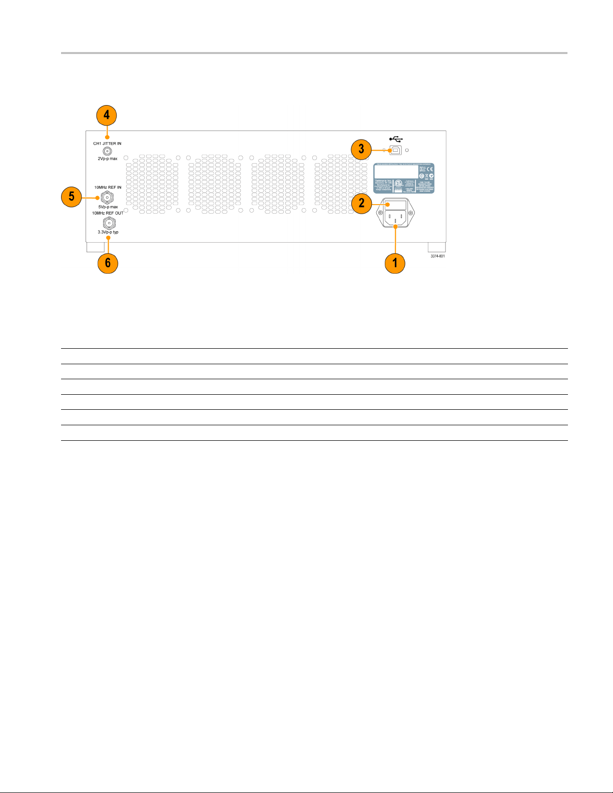
The following i
Figure 2: Rear panel connectors
Table 4:
Item Descrip
1
2 F use holder
3
4JITTERIN
5
6
Rear panel connectors
AC line r
USB con
10 MHz REF IN
10 MH
eceptacle
nection
zREFOUT
Connect
Line fu
Connec
SMA in
BNC in
BNC o
llustration and table describe the rear panel connectors.
tion
the appropriate power cord here.
se, 5 X 20 mm, 2 A, 250 V, SLO BLO
t the USB cable here to control the instrument from an external computer.
put for external jitter insertion (Option HFJIT)
put for external frequency reference
utput for buffered version of the frequency reference (internal or external)
PPG4001 Pattern Generator User Manual 5
Page 22
Functional verification
Functional ve
Instrument setup
rification
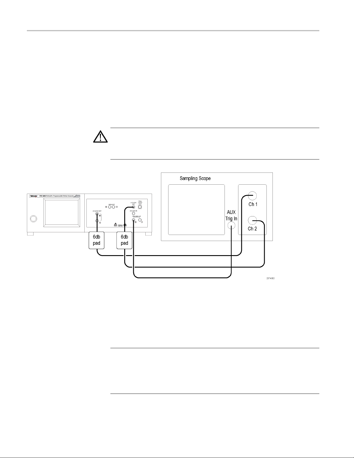
Atypicalse
following figure. The diagram uses only the + side of all differential connections,
the - side can be tested in the same manner. Use a Tektronix DSA8300 Digital
Serial Analyzer Sampling Oscilloscope or similar for functional verification.
CAUTION. Damage to the pattern generator and/or associated equipment can
occur if the input and output voltage ratings are exceeded. Check the input and
output vo
electrical attenuators where voltage ratings are commonly exc eeded.
tup for verifying the pattern generator operation is shown in the
ltage ratings for your equipment. The following illustration shows
Figure 3: Verification setup
Power on and verify instrument operation
The following steps assume the unit is connected as shown in the verification
setup.
NOTE. Note: The generator is internally tem perature compensated for timing and
output level continuously and automatically. Internal timing calibration will also
take place whenever the frequency is set (either manually or through remote
programming). Setting the frequency (or resetting the frequency to its current
value) is recommended after an initial 20-minute warm-up, or if a significant
change in ambient temperature has occurred during operation.
6 PPG4001 Pattern Generator User Manual
Page 23

Functional verification
1. Push front pane
The green light on the switch turns on.
The instrument goes through the start-up sequence.
TheMainmenudisplaysonthetouchscreen.
2. Select UTILITY by touching the on-screen button.
3. Select SAVE.
4. Select REC
5. Select BACK.
6. Select MAIN.
7. Turn OUTPUT ON.
8. Use the AUTO SCALE function on the sampling oscilloscope to identify and
display signals.
9. Adjust the sampling oscilloscope voltage, timing and display settings as
needed.
Channel 1 shows a square wave at the default clock rate.
l on/off switch.
ALL DEFAULTS (The instrument loads all the default settings.)
Channel 2 shows PRBS data with pattern trigger.
utput should be similar to the following figure (the displayed data
The o
pattern may differ).
PPG4001 Pattern Generator User Manual 7
Page 24

Functional verification
Verify the eye diagram
Figure 4: Clock (top) and data (bottom) waveforms
1. Select
2. Select TRIGGER.
3. Select TRIGGER TYPE = CLK/N.
4. Set NDIVISORto 64.
5. Turn off the display on the oscilloscope channel 1 (clock signal).
UTILITY.
8 PPG4001 Pattern Generator User Manual
Page 25

Functional verification
6. Adjust the samp
Output should be similar to the following figure.
ling oscilloscope amplitude, timing and display as needed.
Check
Data
Figure 5: Typical eye diagram example
other settings
Access the remaining menus to experiment with other settings.
and clock output instructions
Each side of the d ifferential signal has a typical voltage swing of from 0 V
to -500 mV.
Treat the outputs with care as they are static sensitive.
PPG4001 Pattern Generator User Manual 9
Page 26

Functional verification
For DC-co upled
Terminate the DUT or load w ith 50 to ground.
Terminate any unused output 50 to ground.
For AC-coupled use:
Provide a 50 to ground path prior to any DC block (a bias tee with
50 to ground. For example, use a bias tee, model number PSPL5542,
available from Tektronix.).
Terminate any unused output 50 to ground.
use:
10 PPG4001 Pattern Generator User Manual
Page 27

Input and output descriptions
Overview
RF connectors
Connector torque
specifications
Data out and /Data out
ut and /Trig out
Trig o
Data and Clock front panel RF connectors are 2.4 mm. All o ther front panel RF
connections are SMA.
Minimum:
Recommend
Maximum:
NOTE. Please note the s pecial termination instructions. (See page 9, Data and
clock ou
These a re the primary outputs from the unit. The outputs can be used single-ended
or differentially. Data pattern and timing can be controlled manually or remotely.
These differential outputs provide a timing reference for viewing the data signals.
The output amplitudes are fixed. Trigger options are PATTERN or CLOCK/N.
When using a pattern trigger, the trigger corresponds to the beginning of a pattern.
The pattern trigger mode can be used with user-defined or PRBS data. For the
CLOCK/N trigger mode, the clock frequency is reduced by a factor of N where
value N is required to be a multiple of 64.
the
ed:
tput instructions.)
2 i n-lbs (0.226 N-m)
7-10 in-lbs (0.791-1.130 N-m)
15 in-lb (1.695 N-m)
Full-clock out
/2 clock out
PPG4001 Pattern Generator User Manual 11
The clock output reflects the data rate; there is one full clock cycle per bit of
data. The clock output is AC coupled and the amplitude is fixed. The internal
ock actually operates over a range of 20 GHz to 40 GHz. When data rates
cl
<20 Gb/s are used, the internal clock will operate at a multiple of the data rate and
bit-stretching is used to produce data at the specified rate.
The /2 clock output reflects one half of the data rate; there is one full clock cycle
per two bits of data. The clock output is AC coupled and the amplitude is fixed.
The internal clock actually operates over a range of 20 GHz to 40 GHz. When
data rates <20 Gb/s are used, the internal clock will operate at a multiple of the
data rate and bit-stretching is used to produce data at the specified rate. The user
interface will indicate the /2 clock rate for this case. A built-in clock divider
can be used to divide the internal clock before it is sent to the /n clock output
(divisors of 1,2,4,8,16).
Page 28

Input and output descriptions
/2 Clk in
Functional block diagram
This is the inpu
a range of 10 GHz to 20 GHz.
The basic functional blocks are shown in the following figure.
t used to supply an e x ternal clock. Clock frequency is restricted to
Data ou
tputs
Output range
Figure 6: Block diagram
The instrument is designed to drive a 50 load. The voltage window is fixed over
a range from 0 V to -500 mV.
ING. To ensure proper operation, never load the output with less than 50 Ω.
WARN
12 PPG4001 Pattern Generator User Manual
Page 29
Graphical user interface (GUI) touch screen
Graphical use
r interface (GUI) touch screen
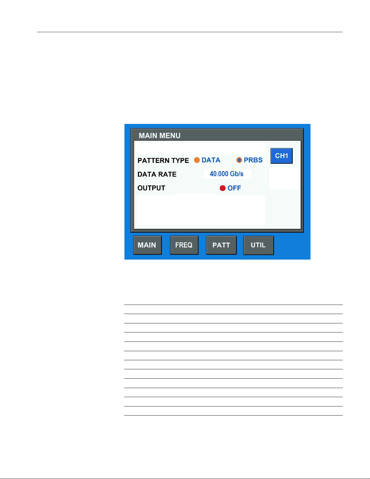
This unit is e
through this user interface. An example of the GUI is shown in the following
figure.
The following table gives a listing of where to find various parameters within
the menu structure.
quipped with touch screen controls. All manual settings are accessed
Figure 7: GUI Main menu
Table 5: GUI menu parameter locations
Parameter Found in menu(s)
10 MHz Ref (int / ext)
Data Rate
External Clock Enable TIMING [EXTFREQ]
Internal Clock Rate TIMING
Jitter Enable
Output Clock Rate TIMING
Pattern Length PATTERN
Pattern Type MAIN, PAT TER N
Pattern (user defined)
PRBS Length
Output ON / OFF MAIN, VOLTS
Recall Pattern
UTILITY
MAIN, TIMING
TIMING [JITTER]
PATT ER N [ DATA ]
PATT ER N
PATTERN [SAVE] [RECALL]
PPG4001 Pattern Generator User Manual 13
Page 30

Graphical user interface (GUI) touch screen
Table 5: GUI menu parameter locations (cont.)
Parameter Found in menu(s)
Recall Setup UTILITY [SAVE] [RECALL]
Save Pattern PATTERN [SAVE] [STORE]
Save Setup UTILITY [SAVE] [STORE]
Trigger Options UTILITY [TRIG GER]
14 PPG4001 Pattern Generator User Manual
Page 31

Jitter insertion (optional feature)
Jitter insert
ion (optional feature)
Jitter sources
Built-in high-frequency
sinusoidal modulation
source (Op
uncorrelated jitter (BUJ,
includedinOptionHFJIT)
Built-in random noise
modula
tion source (Option
tion HFJIT)
Built-in bounded
HFJIT)
The pattern g
page 19, Jitter insertion.)
Programmable frequency from 5 kHz to 100 MHz
Programma
Programmable amplitude up to 50 ps
Programmable modulation data rates from 100 Mb/s to 2.5 Gb/s
Full suite of program mable PRBS sequences
Low-pass filter values 25/50/100 MHz
Programmable amplitude up to 5 ps
enerator can be ordered with a built-in jitter insertion options. (See
ble amplitude up to 50 ps
P-P
P-P
RMS
Built-in low-frequency
sinusoidal modulation
source (Option LFJIT)
External modulation
ce
sour
External modulation input
(Jitter in)
SJ programmable frequency from 10 Hz to 10 MHz, from 5000 UI
0.5 UI
P-P
Amplitude up to 50 ps
5V
maximum input
P-P
Frequency range: DC to 100 MHz
Any waveform (or random)
Total jitter of the instrument (external plus built-in jitter) mu st not exceed the
above specifications for External modulation source.
from 5 kHz to 100 MHz
P-P
P-P
to
PPG4001 Pattern Generator User Manual 15
Page 32

Jitter insertion (optional feature)
16 PPG4001 Pattern Generator User Manual
Page 33

Specifications
Data outputs
Amplitude
Rise/fall time
Data output jitter
Connector type
DC coupled. Each side of the differential pair swings from -500 mV to 0 V.
Ground-referenced CML. Terminated 50 to ground.
Single-ended. 500 mV, typical
Differential. 1.0 V, typical
Scope bandwidth can impact the m ea sured signal rise time.
20 to 80%. 8ps,typical
10 to 90%. 12 ps, typical
Measured at 40 Gb/s with 211-1 PRBS
Total jitter (1E-12). 7ps
Random jitter. 200 fs, RMS, typical @ 40 Gb/s
2.4 mm
,typical
p-p
Output impedance
Clock outputs
Full rate clock output
Half-rate clock output
50 Ω. Single-ended
100 Ω. Differential
AC co upled, single-ended
Frequency. 20 GHz to 40 GHz
Amplitude. 500 mV
Connector type. 2.4 mm
AC coupled, differential
Amplitude. 500 mV
Connector type. 2.4 mm
,typical
p-p
,typical
p-p
PPG4001 Pattern Generator User Manual 17
Page 34

Specifications
/n clock o utput
Trigger output
Data patterns
Pattern type
Data rate
AC coupled, sin
gle ende d
Programmable divider. n = 2, 4, 8, 16
Amplitude. 500 mV
,typical
p-p
Connector type. 2.4 mm
Programmed as pattern trigger or clock/n (with n = multiples of 128)
Amplitude. -500 mV to 0 V, DC coupled
Connector type. SMA
Data (from memory) or PRBS
Programmable/adjustable
PRBS pattern lengths
Data pattern depth
Range. 4Gb/sto40Gb/s
Resolution. 10 kb/s
Accuracy. ±5 ppm
27-1 bits. Polynomial = X7+X6+1
9
2
-1 bits. Polynomial = X9+X5+1
11
2
-1 bits. Polynomial = X11+X9+1
15
2
-1 bits. Polynomial = X15+X14+1
23
2
-1 bits. Polynomial = X23+X18+1
31
2
-1 bits. Polynomial = X31+X28+1
Range. 2to4,194,304bits
Resolution. 1bit
18 PPG4001 Pattern Generator User Manual
Page 35

Specifications
Programmable error
Jitter insertion
High frequency jitter
insertion option
Built-in sine source
insertion
Error insertio
n can be enabled with either single bit error insertion or at a
programmable rate.
Single bit errors. Ye s
Programmable bit errors. 10
-3
to 10
-15
BER
Add-on option for the instrument. Sum of external, in ternal sine, interna
and BUJ. Exceeding the range can generate errors.
Total modulation range. 50 ps
p-p
Programmable from either the front panel touch screen or remote control.
Frequency range. 5kHzto100MHz
Amplitude range. 0to50ps
p-p
Accuracy. ±10%, typical
l noise,
Built-in random noise
source
Built-in BUJ source
External modulation input
Programmable from either the front panel touch screen or remote control.
Amplitude range. 0to5
RMS
Accuracy. ±10%, typical
Programmable from either the front panel touch screen or remote control.
Amplitude range. 0to50ps
p-p
Modulation data rates. 100Mb/sto2.5Gb/s
PRBS sequences. 7,9,11,15,23,31
Filter values. 25/50/100 MHz filters
DC coupled, 3 dB bandwidths
Frequency range. DC to 100 MH
Amplitude range. 0to50ps
Maximum input. 5V
p-p
z
p-p
PPG4001 Pattern Generator User Manual 19
Page 36

Specifications
Low frequency jitter
insertion (Option LFJIT)
Trigger system
Trigger wa veform
Add-on option
SJ modulation range curve points.
Parameter Value
10 Hz f
100 Hz f
1kHzf
mod
10 kHz f
100 kHz f
1MHzf
2MHzf
10 MHz f
mod
mod
mod
mod
mod
mod
mod
5000 UI
2000 UI
2000 UI
2000 UI
100 UI
10 UI
p-p
1UI
p-p
0.5 UI
p-p
p-p
p-p
p-p
p-p
p-p
Pattern mode. 1 pattern per trigger for pattern length = multiple of 128
128 patterns per trigger for other pattern lengths
Clock/n mode. 128 through (2
32
- 128), n= any multiple of 128 in that range
Output impedance
Connector type
Clock inputs
Frequency range
Input signal
High level
Low level
Duty cycle. 50%, for either Pattern or Clock/n
0V,typical
-500 mV, typical
50 , DC-coupled
SMA
10 GHz to 20 GHz, half rate
500 mV
, typical, AC coupled
p-p
Maximum input signal
800 mV
p-p
20 PPG4001 Pattern Generator User Manual
Page 37

Specifications
Input impedance
Reference clock
Input frequen
Maximum input signal
Input impedance
10 MHz reference
cy range
Input signal
Output signal
input/output
50 , AC-couple
100 MHz
1V
, typical, 50% duty square wave
p-p
5V
, ±10 V DC, Damage threshold
p-p
50 ,AC-cou
1.2 V
Yes, BNC connector
, typical, Square wave
p-p
d
pled
Control interfaces
Front pan
Computer programmable
el touchscreen
interface
Yes, edit all instrument settings
GUI
USB TMC, program all instrument settings
PPG4001 Pattern Generator User Manual 21
Page 38

Specifications
Physical characteristics
Front panel width (with
mounting tabs)
Height
Width
Depth (rack mount)
Weight
Operating temperature
48.3 cm (19.0 in)
13.3 cm (5.25 in)
45.1 cm (17.75 in)
35.1 cm (13
11.1 kg (24.5 lbs)
0°Cto40°C(32°Fto104°F)
.8 in)
22 PPG4001 Pattern Generator User Manual
Page 39

Remote programming
USB interface
All automated programming is accomplished through a USB TMC interface.
Command information
Sequential vs. overlapped
Long and s
Channel numbers
hort form
All commands are sequential commands. Sequential commands complete before
the next is executed. This means that completion of any command can be verified
by following it with any query. When the query response is received, the previous
command is certain to b e complete.
Commands have both a long and short form. In command descriptions, the long
form is the entire command while the short form is the part in capital letters.
Commands must be either the exact long form or the exact short form, other
combin
The PPG4001 pattern generator is currently available as a single-channel unit
(Channel 1) Commands for non-existent channels are not valid.
ations will create an error.
PPG4001 Pattern Generator User Manual 23
Page 40

Common commands
Common comman
Summary
Command Description
*IDN? Read Instrument's Identification string
*RST Reset instrument to default settings
Reference
*IDN?
Read the instrument’s identification string.
The returned s tring has the following format:
“Tektronix In c., Mod el code,SN,FWREV” Where:
ds
Model code = 12604
SN = serial number
FWREV
= firmware revision
*RST
Resets the instrument to default settings. This sets all parameters to their default
values, including output enable, pattern length, a nd pattern data.
24 PPG4001 Pattern Generator User Manual
Page 41

Regular commands
Summary
The following table provides a summary of the remote control commands.
Command Parameters Default Description
DIGITAL sub
:DIGital
:PAT Tern
:SIGNal [:POS|:NEG]:CROSsover
Memory subsystem
:STORe
system
:LENGth
:TYPE
:PLENgth <numeric>
:DATA <numeric>,
:HDATa <numer
or
:SERR
:ERATe <numeric> 1e-3 inserts error into the
:ERATe:STATe OFF | ON OFF
:BSHift
[:VALue] <numeric>
:PDATa <string>
:STATe
<numeric> 8
DATA | PR
<numer
<arbitrary block>
<numeric>,
<arbitrary block>
none
<numeric> 0
<string>
BS
ic>,
ic>,
set/query Pattern
Length
PRBS set/que
7
1000…
1000…
n/a
50% set/query crossing
n/a
n/a
ry Pattern type
ry PRBS length
set/que
ery Pattern Data
set/qu
set/query Pattern
Data in hexadecimal
cter format
chara
insert a single error
he data output
into t
output at the
data
specified rate
le error rate
enab
injection into the data
output
shift the pattern by the
ecified number of
sp
bits relative to nominal
position
oint
p
store pattern data in
system me mory
store instrument
settings in system
memory
Regular commands
(See page 29.)
(See pag
(See pag
(See pa
(See page 32.)
(See p
(See
(See page 33.)
(See page 34.)
(See page 34.)
(See page 35.)
(See page 35.)
e 29.)
e 30.)
ge 31.)
age 33.)
page 33.)
PPG4001 Pattern Generator User Manual 25
Page 42

Regular commands
Command Parameters Default Description
:LOAD
:PDATa <string>
:STATe
:MOVE
:PDATa <string>,
:STATe
:DELete
:PDATa <string>
:STATe
:CATalog
:PDATa
:STATe n/a n/a get list of instrument
put subsystem
Out
TPut0
:OU
OURce
:S
IVider
:D
:OUTPut
:POLarity NORMal |
[:STATe] OFF | ON OFF set/query data output
:OUTPut
:CLOCk:DIVider
<string>
<string>
<string>,
<string>
>
<string
n/a n/a get list of stored
Riodic |
PE
BITStream
umeric>
<n
INVerted
<numeric> varies programs the clock
n/a
n/a
n/a
n/a
n/a
n/a
TS
BI
8
12
NORM set/query data output
recall patter
from system memory
recall instr
settings from system
memory
rename existing
pattern data file in
system mem
rename existing
instrume
file in system memory
delete stored pattern
data file
memory
delete i
settings file in system
memory
patte
system memory
settings files in system
memo
se
event
set/query trigger
divider
polarity
enable/disable status
divider output for the
internal clock
nt settings
in system
nstrument
rn data files in
ry
t/query trigger out
n data
ument
ory
(See page 35.)
(See page 36.)
(See page 36.)
(See page
(See pag
(See page 37.)
(See page 37.)
(See page 38.)
ee page 38.)
(S
(See page 38.)
(See page 39.)
(See page 39.)
(See page 39.)
36.)
e 37.)
26 PPG4001 Pattern Generator User Manual
Page 43

Command Parameters Default Description
Sense subsystem
:SENSe:ROSCillator
:SOURce INTernal |
Source subsystem
[:SOURce]
:FREQuency[:CW|:FIXed]
PM [:HF]
:[:STATe] OFF | ON OFF set/query overall
al1[:DEViation]
:INTern
:INTernal1:FREQuency
rnal1:STATe
:INTe
:INTernal2[:DEViation] <numeric> 0 ps
Tern al2: STATe
:IN
:INTernal4:CALibration GAUSsian | CEI GAUS set/query BUJ
:INTernal4[:DEViation] <numeric> 0 ps
NTernal4:FILTer
I
:INTernal4:FREQuency
:INTernal4:PLENgth <numeric> 31
:INTernal4:STATe OFF | ON OFF set/query internal
EXTernal
<numeric>
<numeri
<numeric> 1 MHz
OFF | O
OFF
<
<numeric>
c>
N
|ON
numeric>
INT
30 G Hz set/query clock
0ps
OFF set/q
OFF set
00 MHz
1
2 GHz set/query internal HF
set/query 10 MHz
reference source
frequenc
jitter i
enable/disable status
set/query internal HF
sine jitter amplitude
set/query internal HF
sine j
HF sine jitter
enable/disable status
set/query internal
rand
random jitter
enable/disable status
am
s
BUJ jitter amplitude
set/query internal HF
BUJ generator filter
bandwidth
BUJ generator clock
frequency
set/query internal HF
BUJ generator PRBS
length
HF BUJ jitter
enable/disable status
y
nsertion
itter frequency
uery internal
om jitter amplitude
/query internal
plitude cal
et/query internal HF
Regular commands
(See page 40.)
(See page 40.)
(See page 40.)
(See page 41.)
(See page 41.)
age 41.)
(See p
(See page 42.)
epage42.)
(Se
(See page 42.)
Seepage43.)
(
(See page 44.)
(See page 44.)
(See page 44.)
(See page 45.)
PPG4001 Pattern Generator User Manual 27
Page 44

Regular commands
Command Parameters Default Description
:PM:LF
[:INTernal3][:DEViation] <numeric> 0 UI
[:INTernal3]:FREQuency
[:INTernal3]:STATe OFF | ON OFF set/query internal
:VOLTage#[:POS|:NEG][:LEVel][:IMMediate]
[:AMPLit
:OFFSet
:TERMination <numeric> 0 V
:VOLTage#[:LEVel][:IMMediate]
:LINK
System subsystem
:SYSTem:ERRor[:NEXT]?
Trigger subsystem
:TRIGger
:SOURce IMMediate |
:LOCK
ude]
<numeric> 10 kHz
<numeric
<numeric> 0 V
none
EXTernal
none
>
500 mV
OFF Enable/disable Linking (See page 46.)
n/a
IMM
n/a
set/query int
sine jitter amplitude
set/query internal LF
sine jitter frequency
LF sine jitt
enable/disable status
set/query data
amplitude
set/query data offset (See page 46.)
set/query data term (See page 46.)
query error queue
set/query clock source (See page 47.)
initiate lock to external
clock
ernal LF
er
(See page 44.)
(See page 45.)
(See page 45.)
(See page 45.)
(See page 47.)
(See page 48.)
28 PPG4001 Pattern Generator User Manual
Page 45

Reference
:DIGital:PATTern:LENGth
Reference
Form
Parameters Numeric
Value Coupling
Range Coupling
Default
Description
Example
Set & Query
None
None
8
Programs the Pattern Length. This value is only relevant if the pattern type is DATA.
The length can be any integer from 2 through 4,194,304.
Set pattern length to 56
:DIG:PATT:LENG 56
Query pattern length
:DIG:PATT:LENG?
:DIGital:PATTern:TYPE
Form
eters
Param
Value Coupling
Range Coupling
Default PRBS
cription
Des
Example
Set & Query
DATA | PRBS
None
None
grams the Pattern Type.
Pro
t the pattern type to PRBS
Se
:DIG:PATT:TYPE PRBS
Query pattern type
DIG:PATT:TYPE?
:
PPG4001 Pattern Generator User Manual 29
Page 46

Reference
:DIGital:PAT
Form
Parameters
Value Coupling
Range Coupling
Default
Description
Example
Tern:PLENgth
Set & Query
7|9|11|15|23|31
None
None
7
Programs the Pattern PRBS Length. PRBS Length is specified as 2
specified value. This value is only relevant if the pattern type is PRBS.
Set the PRBS length to (2
:DIG:PATT:PLEN 7
Query PRBS length
:DIG:PATT:PLEN?
N
-1, where N is the
7
-1)
30 PPG4001 Pattern Generator User Manual
Page 47

Reference
:DIGital:PAT
Form
Parameters <start address>,<bit count>,<data>
Value Coupling
Range Coupling
Default Default data is a 1 in position 1, all other bits are 0 .
Description
Example
Tern:DATA
Set & Query
<start address> is numeric, and is the bit number in pattern data memory of the first bit to write.
<bit count> is the number of bits to write into pattern data memory.
<data> is an arbitrary block of program data as defined in IEEE-488.2-1992, section 7.7.6.2. It
starts with a "#" character, followed by a single character representing the length of the length,
then 1 to 5 characters specifying the length as a decimal number, then the program data.
None
None
Programs the pattern data memory. Each byte of pattern data is a character (0 or 1)
representing one bit of pattern data. The start address can be any bit location, 1 – <max
address>. <max address> is > is 4,194,304. The bit count can be any number 1 – 1024. The
entire pattern data memory is accessible for reads or writes, even outside the range of the
current pattern length setting. The bit count parameter and the length of the data block must
match. (<start address> + <bit c ount>) must be ≤ (<max address> + 1).
:DIG:PATT:DATA 1,16,#216010000 01 01 01 001 0
This command does the following:
Starts loading the Ch 1 data into bit location 1.
Specifies that 16 bits of data will be loaded.
In the <data>:
#: signifies the beginning of the block
2: indicates that the length of the data length is two characters
16: indicates that data length is 16 bytes. (16 ASCII characters)
0100000101010010: is the character representation of the data
Thus, bits 1 through 16 in the channel 1 pattern data memory will be set to 0100000101010010.
:DIG:PATT:DATA? 1,8
This query reads 8 bits of pattern data starting from address 1. Given the above pattern data
memory contents, the response would be "#1801000001".
PPG4001 Pattern Generator User Manual 31
Page 48

Reference
:DIGital:PAT
Form
Parameters <start address>,<bit count>,<data>
Value Coupling
Range Coupling
Default Default data is a 1 in position 1, all other bits are 0.
Description
Example
Tern:HDATa
Set & Query
<start address> is numeric, and is the bit number in pattern data memory of the first bit to write.
<bit count> is the number of bits to write into pattern data memory.
<data> is an arbitrary block of program data as de fi ned in IEEE-488.2-1992, section 7.7.6.2. It
starts with a "#" character, followed by a single character representing the length of the length,
then 1 to 5 characters specifying the length as a decimal number, then the program data.
None
None
Programs the pattern data memory using hexadecimal character format. Each byte of pattern
data is a hexadecimal character (0-9, A-F or a-f) representing four bits of pattern data. The
start address can be any bit location, 1 – <max address>. <max address> is 4,194,304. The
bit count can be any number 1 – 4096. The entire pattern data memory is accessible for reads
or writes, even outside the range of the current pattern length setting.
The bit count parameter must be equal to 4 times the length of the data block or up to 3 bits
fewer. If it is fewer, then the extra bits in the last data byte are ignored. (<start address> +
<bit count>) must be ≤ (<max address> + 1).
:DIG:PATT:HDAT 1,16,#144152
This command does the following:
Starts loading the Ch 1 data into bit location 1.
Specifies that 16 bits of data will be loaded.
In the <data>:
#: signifies the beginning of the block
1: indicates that the length of the data length is one character
4: indicates that data length is 4 bytes. (4 A SCII characters)
4152: is the c haracter representation of the data
Thus, bits 1 through 16 in the channel 1 pattern data memory will be set to 0100000101010010.
:DIG:PATT:HDAT? 1,8
This query reads 8 bits of pattern data starting from address 1. Given the above pattern data
memory contents, the response would be "#1241".
Note that if the query requests a number of bits that is not a multiple of 4, s ome bits in the last
byte will not be meaningful, and will be 0.
32 PPG4001 Pattern Generator User Manual
Page 49

Reference
:DIGital:PAT
Form
Parameters None
Value Coupling
Range Coupling
Default n/a
Description
Example Insert one error into the data output.
Tern:SERRor
Set
None
None
Inserts a single error into the data output. Error insertion w orks for either data patterns or
PRBS patterns. If there is no pattern currently being output, for instance if the outputs are
disabled, the command has no effect.
:DIG:PATT:SERROR
:DIGital:PATTern:ERATe
Form
ters
Parame
oupling
Value C
Coupling
Range
lt
Defau
Description
ple
Exam
Set & Query
c
Numeri
None
None
1e-3
rt errors into the data output at the specified rate. Error rate insertion w orks for either data
Inse
patterns or PRBS patterns when error rate is enabled.
rt 2E-12 error rate into the data output.
Inse
:DIG:PATT:ERAT 2e-12
Gital:PATTern:ERATe:STATe
:DI
Form
Parameters
Value Coupling
Range Coupling
Default OFF
Description
Example Enable error insertion rate into the data output.
Set & Query
OFF | ON
None
None
Enables insertion of errors into the data output at a rate specified by the :DIGital:PATTern:ERATe
command.
:DIG:PATT:ERAT:STAT ON
PPG4001 Pattern Generator User Manual 33
Page 50

Reference
:DIGital:PAT
Form
Parameters Numeric
Value Coupling
Range Coupling
Default
Description
Example
Tern:BSHift
Set & Query
None
None
0
Shift the pattern by the specified number of bits relative to nominal position.
Insert bit shift of 10 into the data output.
:DIG:PATT:BSH 10
:DIGital:SIGNal[:POS|:NEG]:CROSsover:[VALue]
Form
Parameters
Value Coupling
Range Coupling
Default 50%
Description Programs the NRZ signal crossing point. Positive and negative outputs have independent
Example
Set & Query
Numeric [no units, value is in %]
None
None
crossing point adjustment, specified by [:POS | :NEG].
: to maintain normal complement behavior, if the POS output crossing point is set to
Note
50+X, then the NEG should be set to 50-X. For example, if the POS were set to 57%, the
NEG would be set to 43%.
Set negative output crossing point to 45 % .
IG:SIGN:NEG:CROS 45
:D
Query negative output crossing point?
:DIG:SIGN:NEG:CROS?
34 PPG4001 Pattern Generator User Manual
Page 51

Reference
:MMEMory:STO
Form
Parameters
Value Coupling
Range Coupling
Default N/A
Description
Example
Re:PDATa
Set
String
None
None
Store the current pattern data into the system memory. The pattern length and all pattern data
up to the pattern length are stored. The filename can be up to 8 characters long and is not
case-sensitive. Filenames must consist of only alphanumeric characters.
Store the pattern data in system memory.
:MMEM:STOR:PDAT “PATT1011”
:MMEMory:STORe:STATe
Form
Parameters
Coupling
Value
Coupling
Range
ult
Defa
Description
Example
Set
String
None
None
N/A
Sto
stored except for pattern data, pattern length and output enable status. The filenamecanbeup
to 8 characters long and is not case-sensitive. Filenames must consist of only alphanumeric
cha
St
:MMEM:STOR:STAT “PARAM22”
re the instrument setting into the system memory. Every parameter of the instrument is
racters.
ore the parameters in system memory.
MMEMory:LOAD:PDATa
:
Form
Parameters
Value Coupling
Range Coupling
Default N/A
Description
Example
Set
String
None
None
Recalls the pattern data from a saved file in system memory. The pattern length and all data up
to the pattern length are recalled. Pattern memory addresses above the pattern length are not
changed. The filename can be up to 8 characters long and is not case-sensitive. Filenames
must consist of only alphanumeric characters.
Recall the pattern data from file “PATT1011”.
MMEM:LOAD:PDAT “PATT1011”
PPG4001 Pattern Generator User Manual 35
Page 52

Reference
:MMEMory:LOA
Form
Parameters
Value Coupling
Range Coupling
Default N/A
Description
Example
D:STATe
Set
String
None
None
Recalls the instrument setting from a saved file in system memory. Every parameter of the
instrument is recalled except for pattern data, pattern length and output enable status. The
filename can be up to 8 characters long and is not case-sensitive. Filenames must consist
of only alphanumeric characters.
Recall the instrument settings from file “PARAM22”.
:MMEM:LOAD:STAT “PARAM22”
:MMEMory:MOVE:PDATa
Form
ters
Parame
Value Coupling
Range Coupling
Default N/A
cription
Des
Example
Set
String
None
None
Rename the existing saved pattern data file in system memory. The filename can be up to
8 characters long and is not case-sensitive. Filenames must consist of only alphanumeric
cha
Re
:MMEM:MOVE:PDAT “PATT1011”, “PATT010 1”
racters.
name the pattern data file PATT1011 to PATT0101.
MMEMory:MOVE:STATe
:
Form
Parameters
Value Coupling
Range Coupling
Default N/A
Description
Example
Set
String
None
None
Rename the existing saved instrument settings fi le in system memory. The filename can be up
to 8 characters long and is not case-sensitive. Filenames must consist of only alphanumeric
characters.
Rename the instrument settings filePARAM22toPARAM.
:MMEM:MOVE:STAT “PARAM22”, “PARAM”
36 PPG4001 Pattern Generator User Manual
Page 53

:MMEMory:DELete:PDATa
Reference
Form
Parameters
Value Coupling
Range Coupling
Default N/A
Description
Example
Set
String
None
None
Deletes an existing saved pattern data file in system memory. The filename can be up to
8 characters long and is not case-sensitive. Filenames must consist of only alphanumeric
characters.
Delete the existing pattern data file PATT0101.
:MMEM:DEL:PDAT “PATT0101”
:MMEMory:DELete:STATe
Form
Parameters
Value Coupling
Range Coupling
Default N/A
Description
mple
Exa
Set
String
None
None
Deletes an existing saved instrument settings file in system memory. The filename can be up
to 8
characters.
Delete the existing instrument settings file PARAM.
:MMEM:DEL:STAT “PARAM”
characters long and is not case-sensitive. Filenames must consis t of only alphanumeric
:MMEMory:CATalog:PDATa?
Form
Parameters None
Value Coupling
Range Coupling
Default N/A
Description
Example
PPG4001 Pattern Generator User Manual 37
Query
None
None
Get the list of pattern data files s tored in system memory. All the filenames stored in the
system memory are returned as capital letters.
Get the list of pattern data filesstoredinsystemmemory.
:MMEM:CAT:PDAT?
Page 54

Reference
:MMEMory:CAT
Form
Parameters None
Value Coupling
Range Coupling
Default N/A
Description
Example
alog:STATe?
Query
None
None
Get the list of instrument settings filesstoredinsystemmemory.Allthefilenames stored in the
system memory are returned as capital letters.
Get the list of instrument settings filesstoredinsystemmemory.
:MMEM:CAT:STAT?
:OUTPut0:SOURce
Form
ters
Parame
Value Coupling
Range Coupling
Default
ription
Desc
ample
Ex
Set & Query
PERiodic | BITStream
None
None
PERio
Prog
Set the trigger out event to bit stream.
:OUTP0:SOUR BITSTREAM
dic
rams the trigger out event.
iodic means the trigger will output a signal whose frequency is the clock rate divided
PER
by N, where N is the trigger divider setting.
BITStream means trigger pulses will be aligned with the pattern length.
:OUTPut0:DIVider
Form
Parameters Numeric
Value Coupling
Range Coupling
Default
Description
Example
38 PPG4001 Pattern Generator User Manual
Set & Query
None
None
128
Programs the trigger divider. This is meaningful only if the trigger output event is set to
periodic.. For the PPG4001, valid values are multiples of 128.
Set the trigger divider to 128.
:OUTP0:DIV 128
Page 55

Reference
:OUTPut:POLa
Form
Parameters
Value Coupling
Range Coupling
Default NORMal
Description
Example
rity
Set & Query
NORMal | INVerted
None
None
Programs the polarity of the channel outputs.
Set for inverted output
:OUTPUT:POLARITY INV
:OUTPut[:STATe]
Form
ters
Parame
Value Coupling
Range Coupling
Default OFF
ription
Desc
Example Disable the output.
Set & Query
OFF | ON
None
None
Programs the enable/disable status of the channel outputs. If the unit has optional
pre-emphasis outputs, the state of the pre-emphasized output is set together with that of
standard output.
the
TP OFF
:OU
:OUTPut:CLOCk:DIVider
Form
Parameters
Value Coupling
Range Coupling
Default Varies with model & options. The minimum allowed value is either 1 or 2.
Description
Example
Set & Query
1|2|4|8|16
None
None
Programs the clock output divider. The input to this divider is internal clock, and the output from
the divider goes to the c lock output or to the divided clock output if the full rate & divided outputs
are separate. The max and min valid values depend on the instrument model and options.
Program clock divider for 8.
:OUTP:CLOC:DIV 8
PPG4001 Pattern Generator User Manual 39
Page 56

Reference
:SENSe:ROSCi
Form
Parameters
Value Coupling
Range Coupling
Default
Description
Example
llator:SOURce
Set & Query
INTernal | EXTernal
None
None
INT
Programs the 10 MHz reference source.
Set the 10 MHz reference source to use the internal reference.
:SENSE:ROSCILLATOR:SOURCE INT ERN AL
[:SOURce]:FREQuency[:CW|:FIXed]
Form
ters
Parame
oupling
Value C
Coupling
Range
lt
Defau
Description
mple
Exa
Set & Query
c[Hz]
Numeri
None
None
30e9
rams the internal clock frequency, and also selects the internal clock as clock source if
Prog
it is not already selected.
Set frequency to 28 G Hz.
:FREQ 28e9
[:SOURce]:PM[:HF][:STATe]
Form
Parameters
Value Coupling
Range Coupling
Default OFF
Description
Example Enable overall HF jitter insertion.
Set & Query
OFF | ON
None
None
Programs the overall channel jitter insertion enable/disable status. The HF sources are HF
sine, random, and external. If enabled, the external jitter source is enabled and the internal
sources are set according to their i ndividual controls.
:PM ON
40 PPG4001 Pattern Generator User Manual
Page 57

Reference
[:SOURce]:PM
Form
Parameters
Value Coupling
Range Coupling
Default
Description
Example
[:HF]:INTernal1[:DEViation]
Set & Query
Numeric [S]
None
None
0ps
Programs the peak-to-peak amplitude of the channel internal sine jitter source. Units are in
seconds.
Set the internal HF sine jitter source to 11 ps peak-to-peak.
:PM:INT1 11ps
[:SOURce]:PM[:HF]:INTernal1:FREQuency
Form
Parameters Numeric [Hz]
Value Coupling
Range Coupling
Default
ription
Desc
mple
Exa
Set & Query
None
None
1MHz
Programs the frequency of the channel internal HF sine jitter source. Units are Hz.
Set sinusoidal jitter frequency to 1.3 MHz.
:PM:INT1:FREQ 1.3MHz
[:SOURce]:PM[:HF]:INTernal1:STATe
Form
Parameters
Value Coupling
Range Coupling
Default OFF
Description
Example Enable the internal HF sine jitter source.
Set & Query
OFF | ON
None
None
Programs the channel internal HF sine jitter source enable/disable status. Both this setting and
[:SOURce]:PM[:HF][:STATe] for a given channel must be on for HF sine jitter to be applied.
:PM:INTERNAL1:STATE ON
PPG4001 Pattern Generator User Manual 41
Page 58

Reference
[:SOURce]:PM
Form
Parameters
Value Coupling
Range Coupling
Default
Description
Example
[:HF]:INTernal2[:DEViation]
Set & Query
Numeric [S]
None
None
0ps
Programs the rms amplitude of the channel internal random jitter s ource. Units are in seconds.
Set the internal random jitter source to 7 ps rms.
:PM:INT2 7ps
[:SOURce]:PM[:HF]:INTernal2:STATe
Form
ters
Parame
Value Coupling
Range Coupling
Default OFF
ription
Desc
Example Disable the internal random jitter source.
Set & Query
OFF | ON
None
None
Programs the channel internal random jitter source enable/disable status. Both this setting and
[:SOURce]:PM[:HF][:STATe] for a given channel must be on for random jitter to be applied.
:PM:INTERNAL2:STATE OFF
[:SOURce]:PM[:HF]:INTernal4:CALibration
Form
Parameters
Value Coupling
Range Coupling
Default GAUS
Description
Example
Set & Query
GAUSsian | CEI
None
None
Programs the calibration source for the BUJ amplitude. BUJ amplitude is calibrated under
two conditions; select the source closest to the current settings. The settings for each cal
are given below.
Frequency Filter Plength
Gaussian 2 Gb/s
CIE 1.1 Gb/s
Select the CEI calibration.
:PM:INTERNAL4:CAL CEI
100 MHz 31
100 MHz
7
42 PPG4001 Pattern Generator User Manual
Page 59

Reference
[:SOURce]:PM
Form
Parameters
Value Coupling
Range Coupling
Default
Description
Example
[:HF]:INTernal4[:DEViation]
Set & Query
Numeric [S]
None
None
0ps
Programs the peak-to-peak amplitude of the channel internal BUJ jitter source. Units are
Seconds.
Set the internal BUJ random jitter source to 12 ps peak-to-peak.
:PM:INT4 12ps
[:SOURce]:PM[:HF]:INTernal4:FILTer
Form
Parameters Numeric [Hz]
Value Coupling
Range Coupling
Default
ription
Desc
Example
Set & Query
None
None
z
100 MH
Programs the bandwidth of the low-pass filter used to generate the BUJ jitter. Units are Hz.
Valid values are 25 MHz, 50 MHz, or 100 MHz. Other values will be rounded to the nearest
id value.
val
the internal BUJ low-pass filter to 50 MHz.
Set
:PM:HF:INT4:FILTER 50MHz
SOURce]:PM[:HF]:INTernal4:FREQuency
[:
Form
Parameters Numeric [Hz]
Value Coupling
Range Coupling
Default 2 GHz
Description
Example
Set & Query
None
None
Programs the clock frequency of the PRBS used to generate the BUJ jitter. Units are Hz.
Set clock frequency of the BUJ PRBS to 1.7 GHz.
:PM:INT4:FREQ 1.7GHz
PPG4001 Pattern Generator User Manual 43
Page 60

Reference
[:SOURce]:PM
Form
Parameters
Value Coupling
Range Coupling
Default
Description
Example
[:HF]:INTernal4:PLENgth
Set & Query
7|9|11|15|23|31
None
None
31
Programs the length of the PRBS used to generate the BUJ jitter. PRBS Length is specified as
N
-1, where N is the specified value.
2
Set PRBS Length of the channel BUJ PRBS to (2
:PM:INT4:PLEN 15
[:SOURce]:PM[:HF]:INTernal4:STATe
Form
Parameters
Value Coupling
Range Coupling
Default OFF
Description
Example Disable the internal BUJ jitter source.
Set & Query
OFF | ON
None
None
Programs the channel internal BUJ jitter source enable/disable status. Both this setting and
OURce]:PM[:HF][:STATe] for a given channel must be on for BUJ jitter to be applied.
[:S
:INTERNAL4:STATE OFF
:PM
15
-1).
[:SOURce]:PM:LF[:INTernal3][:DEViation]
Form
Parameters Numeric [UI]
Value Coupling
Range Coupling LF Sine Jitter F requency
Default
Description
Example
Set & Query
None
0UI
Programs the peak-to-peak amplitude of the internal LF sine jitter source. Units are UI.
Maximum allowed value depends on LF Sine Jitter Frequency. LF jitter is common to all
channels.
Set the internal LF sine jitter source to 2.5 UI peak-to-peak.
:PM:LF:INT3 2.5
44 PPG4001 Pattern Generator User Manual
Page 61

Reference
[:SOURce]:PM
Form
Parameters Numeric [Hz]
Value Coupling
Range Coupling LF Sine Jitter Amplitude
Default
Description
Example
:LF[:INTernal3]:FREQuency
Set & Query
None
10 kHz
Programs the frequency of the internal LF sine jitter source. Units are Hz. Allowed range
depends on LF Sine Jitter Amplitude. LF jitter is common to all channels.
Set the LF sinusoidal jitter frequency to 7.3 kHz.
:PM:LF:INT3:FREQ 7300
[:SOURce]:PM:LF[:INTernal3]:STATe
Form
ters
Parame
Value Coupling
Range Coupling
Default OFF
ription
Desc
Example Enable the internal LF sine jitter source.
Set & Query
OFF | ON
None
None
Programs the internal LF sine jitter source enable/disable status. LF jitter is common to all
channels.
:PM:LF:INTERNAL3:STATE ON
[:SOURce]:VOLTage[:POS|:NEG][:LEVel][:IMMediate]:[:AMPLitude]
Form
Parameters Numeric [V]
Value Coupling N/A
Range Coupling O ffset
Default
Description
Example
Set & Query
500 mV
Programs the amplitude of the output signal for the positive or negative data outputs.
Set positive data amplitude to 1 V.
:VOLT:POS 1V
Query the positive data amplitude.
:VOLT:POS?
PPG4001 Pattern Generator User Manual 45
Page 62

Reference
[:SOURce]:VO
Form
Parameters Numeric [V]
Value Coupling N/A
Range Coupling
Default
Description
Example
LTage[:POS|:NEG][:LEVel][:IMMediate]:OFFSet
Set & Query
Amplitude
0V
Programs the offset of the output signal for the positive or negative data outputs.
Set negative data offset to –0.5 V.
:VOLT:NEG:OFFS –0.5V
Query the negative data offset.
:VOLT:NEG:OFFS?
[:SOURce]:VOLTage[:POS|:NEG][:LEVel][:IMMediate]:TERMination
Form
Parameters Numeric [V]
Value Coupling Offset
Range Coupling Amplitude, Offset
Default
ription
Desc
Example
Set & Query
0V
Programs the user-supplied external termination voltage for the positive or negative data
outputs.
Set positive term voltage to –1.0 V.
LT:POS:TERM –1.0V
:VO
Query the positive voltage..
:VOLT:POS:TERM?
[:SOURce]:VOLTage[:LEVel][:IMMediate]:LINK
Form
Parameters Numeric [V]
Value Coupling Offset
Range Coupling Amplitude, Offset
Default
Description
Example Disable linking between data out and data out complement.
46 PPG4001 Pattern Generator User Manual
Set & Query
0V
When linking is on, the true & complement values for amplitude, offset, and termination of
the channels are coupled together.
:VOLT1:LINK OFF
Query the linking between data out and data out complement.
:VOLT:LINK?
Page 63

Reference
:SYSTem:ERRo
Form
Parameters None
Value Coupling N/A
Range Coupling N/A
Default N/A
Description
Example
r[:NEXT]?
Query
Queries the system error queue. Returns an integer representing the error number and a string
in double quotes containing the error description. The i nteger and string are separated by
a comma.
The error queue may have multiple items that can be retrieved using multiple queries. If the
queue is empty, the response will be: +0,"No error". If the queue receives more errors than it
can hold, the extra errors will be discarded.
Query the error queue.
:SYST:ERR?
:TRIGger:SOURce
Form
Parameters
Value Coupling N/A
Range Coupling N/A
Default
Description Programs the clock source.
xample
E
Set and Query
IMMediate | EXTernal
IMMediate
IMMediate means the internal clock source provides the clock. Clock frequency is set by
[:SOURce]:FREQuency[:CW|:FIXed] command.
the
EXTernal means the signal at the Ext Clock connector provides the clock source. Clock
frequency is equal to the frequency of the external signal.
ter changing to external clock source the generator must be locked to the clock. If external
Af
clock source is in use, the generator must be re-locked to the clock after any interruption
or change in frequency of the clock. The lock process must be successfully completed for
e generator to function properly. See the :TRIGger:LOCK command. (See page 48,
th
:TRIGger:LOCK.)
Set the clock source to internal.
:TRIG:SOUR IMM
PPG4001 Pattern Generator User Manual 47
Page 64

Reference
:TRIGger:LOC
Form
Parameters None
Value Coupling N/A
Range Coupling N/A
Default N/A
Description
Example Lock the generator to the external clock.
K
Set
Initiates the process of locking the generator to the external clock.
After changing to external clock source the generator must be locked to the clock. If external
clock source is in use, the generator must be re-locked to the clock after any interruption or
change in frequency of the clock. The lock process must be successfully completed for the
generator to function properly.
:TRIG:LOCK
48 PPG4001 Pattern Generator User Manual
Page 65

User service
Service offerings
This section describes high-level service information and procedures for your
instrument.
Tektronix provides service to cover repair under warranty and other services that
are designed to meet your specific service needs.
Whether providing warranty repair service or any of the other services
listed below, Tektronix service technicians are well equipped to service your
instruments. Services are provided at Tektronix Service Centers and on-site at
your faci
lity, depending on your location.
Warranty repair service
Calibration and repair
General care
servi
Tektronix warrants this product as described in the warranty statements at the
front of this manual. Tektronix technicians provide warranty service at most
nix service locations worldw ide. The Tektronix product catalog lists all
Tektro
service locations worldwide.
In addition to warranty repair, Tektronix Service offers calibration and other
ces that provide cost-effective solutions to your service needs and quality
servi
ce
standards compliance requirements. Tektronix instruments are supported
worldwide by the leading-edge design, manufacturing, and service resources of
Tektronix to provide the best possible service.
Protect the instrument from adverse weather conditions. The instrument is not
waterproof. Do not store or leave the instrument where the display will be
exposed to direct sunlight for long periods of time.
AUTION. To avoid damage to the instrument, do not expose it to s prays, liquids ,
C
or solvents.
PPG4001 Pattern Generator User Manual 49
Page 66

User service
Preventive maintenance
Preventive maintenance mainly consists of periodic cleaning. Periodic cleaning
reduces instrument breakdown and increases reliability. Clean the instrument as
needed, based on the operating environment. Dirty conditions may require more
frequent cleaning than computer room conditions.
Clean the flat panel display
The flat panel display is a soft plastic display a nd must be treated with care
during cleaning.
CAUTION. Improper cleaning agents or methods can damage the flat panel
display.
Do not use abrasive cleaners or commercial glass cleaners to clean the display
surface.
Do not spray liquids directly on the display surface.
Do not scrub the display with excessive force.
Avoid getting moisture inside the instrument while cleaning the display; use
only enough solution to dampen the wipe.
Clean the flat panel display surface by gently rubbing the display with a
cleanroom wipe (such as Wypall Medium Duty Wipes, #05701, available
from Kimberly-Clark Corporation).
If the d
isopropyl alcohol solution and gently rub the display surface. Avoid using
excess force or you may damage the plastic display surface.
isplay is very dirty, moisten the wipe with distilled water or a 75%
Clean the exterior surfaces
50 PPG4001 Pattern Generator User Manual
Clean the exterior surfaces with a dry, lint-free c loth or a soft-bristle brush. If dirt
remains, use a cloth or swab dampened with a 75% isopropyl alcohol solution. A
swab is useful for cleaning in narrow spaces around the controls and connectors.
Do not u se abrasive compounds on any part of the instrument.
To avoid damaging the instrument follow these precautions:
Avoid getting moisture inside the instrument during external cleaning and use
only enough solution to dampen the cloth or swab.
Do not wash the front-panel power switch. Cover the switch while washing
the instrum ent.
Use only deionized water when cleaning. Use a 75% isopropyl alcohol
solution as a cleanser and rinse with deionized water.
Do not use chemical cleaning agents; they may damage the instrument. Avoid
chemicals that contain benzene, toluene, xylene, acetone, or similar solvents.
Page 67

User service
Battery information
The coin cell ba
replaceable part. The coin cell battery is not rechargeable. Under no circumstances
attempt to recharge the battery.
ttery on the instrument computer motherboard is not a user
Fuse replacement
The instrument is protected by a fuse placed in series with the power line input.
The fuse is conservatively rated and should never open through the life of the
instrument. A blown fuse would generally indicate a problem with the instrument
which requires factory service. It is recommended that you arrange to have the
instrumen
t serviced if you experience a blown fuse.
Repack the instrument for shipment
If the in
tag showing the following information:
strument is to be shipped to a Tektronix service center for repair, attach a
Name of
Address of the owner
Instrument serial number
the product owner
A description of the problems encountered and/or service required
When pack ing an instrument for shipment, use the original packaging. If it is
unavailable or not fit for use, contact your Tektronix representative to obtain
new packaging.
PPG4001 Pattern Generator User Manual 51
Page 68

User service
52 PPG4001 Pattern Generator User Manual
Page 69

Compliance information
This section lists the EMC (electromagnetic compliance), safety, and
environmental standards with which the instrument com p lies.
EMC compliance
EC Declaration of
Conformity
–EMC
Meets intent of Directive 2004/108/EC for Electromagnetic Compatibility.
Complianc
e was demonstrated to the following specifications as listed in the
Official Journal of the European Communities:
EN 61326-1. EMC requirements for electrical equipment for measurement,
control, and laboratory use.
123
CISPR 11. Radiated and conducted emissions, Group 1, Class A
IEC 61000-4-2. Electrostatic discharge immunity
IEC 61000-4-3. RF electromagnetic field immunity
IEC 610
00-4-4. Electrical fast transient / burst immunity
IEC 61000-4-5. Power line surge immunity
IEC 61000-4-6. Conducted RF immunity
IEC 61000-4-11. Voltage dips and interruptions immunity
EN 61000-3-2. AC power line harmonic emissions
EN 61000-3-3. Voltage changes, fluctuations, and flicker
European contact.
Tektronix UK, Ltd.
Western Peninsula
estern Road
W
Bracknell, RG12 1RF
United Kingdom
1
This product is intended for use in nonresidential areas only. Use in residential areas may cause electromagnetic
interference.
2
Emissions which exceed the levels required by this standard may occur when this equipment is connected to a
test object.
3
For compliance with the EMC standards listed here, high quality shielded interface cables should be used.
PPG4001 Pattern Generator User Manual 53
Page 70

Compliance information
Australia / New Zealand
Declaration of
Conformity – EMC
Safety compliance
EU declaration of
conformity – low voltage
Complies with t
following standard, in accordance with ACMA:
CISPR 11. Radi
accordance with EN 61326-1.
Australia / New Zealand contact.
Baker & McKenzie
Level 27, AMP C en tre
50 Bridge Street
Sydney NSW 2000, Australia
This section lists the safety standards with which the product complies and other
safety c
Compliance was demonstrated to the following specification as listed in the
Official Journal of the European Union:
Low Voltage Directive 2006/95/EC.
ompliance information.
he EMC provision of the Radiocommunications Act per the
ated and Conducted Emissions, Group 1, Class A, in
nationally recognized
U.S.
testing laboratory listing
Canadian certification
Additional compliances
Equipment type
Safety class
EN 61010-1. Safety Requirements for Electrical Equipment for Measurement,
Control, and Laboratory Use – Part 1: General Requirements.
UL 61010-1. Safety Requirements for Electrical Equipment for Measurement,
Control, and Laboratory Use – Part 1: General Requirements.
CAN/CSA-C22.2 No. 61010-1. Safety Requirements for Electrical
Equipment for Measurement, Control, and Laboratory Use – Part 1: General
Requirements.
IEC 61010-1. Safety Requirements for Electrical Equipment for
Measurement, Control, and Laboratory U s e – Part 1: General Requirements.
Test and measuring equipment.
Class 1 – grounded product.
54 PPG4001 Pattern Generator User Manual
Page 71

Compliance information
Pollution degree
descriptions
Pollution degree rating
Ameasureofthe
and within a product. Typically the internal environment inside a product is
considered to be the same as the external. Products should be used only in the
environment for which they are rated.
Pollution degree 1. No pollution or only dry, nonconductive pollution occurs.
Products in this category are generally enca psulated, hermetically sealed, or
located in clean rooms.
Pollution degree 2. Normally only dry, nonconductive pollution occurs.
Occasionally a temporary conductivity that is caused by condensation must
be expected. This location is a typical office/home environment. Temporary
condensa
Pollution degree 3. Conductive pollution, or dry, nonconductive pollution
that bec
where neither temperature nor humidity is controlled. The area is p rotected
from direct sunshine, rain, or direct wind.
Pollution degree 4. Pollution that generates persistent conductivity through
conductive dust, rain, o r snow. Typical outdoor locations.
tion degree 2 (as defined in IEC 61010-1). Rated for indoor, dry location
Pollu
use only.
contaminants that could occur in the environment around
tion occurs only when the product is out of service.
omes conductive due to condensation. These are sheltered locations
Measurement and
voltage category
over
descriptions
Mains overvoltage
category rating
Measurement terminals on this product may be rated for measuring mains voltages
m one or more of the following categories (see specific ratings marked on
fro
the product and in the manual).
tegory II. Circuits directly connected to the building wiring at utilization
Ca
points (socket outlets and similar points).
ategory III. In the building wiring and distribution system.
C
Category IV. At the source of the electrical supply to the building.
NOTE. Only mains power supply circuits have an overvoltage category rating.
Only measurement circuits have a measurement category rating. Other circuits
within the product do not have either rating.
Overvoltage category II (as defined in IEC 61010-1).
PPG4001 Pattern Generator User Manual 55
Page 72

Compliance information
Environmental considerations
This section provides information about the environmental impact of the product.
Product end-of-life
handling
Restriction of hazardous
substances
Observe the f
Equipment recycling. Production of this equipment required the extraction and
use of n atural resources. The equipment may contain substances that could be
harmful to the environment or human health if improperly handled at the product’s
end of life. To avoid release of such substances into the environment and to
reduce the
an appropriate system that will ensure that most of the materials are reused or
recycled appropriately.
This pr
and is not required to comply with the s ubstance restrictions of the recast RoHS
Directive 2011/65/EU until July 22, 2017.
ollowing guidelines when recycling an instrument or component:
use of natural resources, we encoura ge you to recycle this produc t in
This symbol indicates that this product complies with the applicable European
Union re
on waste electrical and electronic equipment (WEEE) and batteries. For
information about recycling options, check the Support/Service section of the
Tektr on
oduct is classified as an industrial monitoring and control instrument,
quirements according to Directives 2012/19/E U and 2006/66/EC
ixWebsite(www.tektronix.com).
56 PPG4001 Pattern Generator User Manual
Page 73

Index
A
accessories, 1
B
battery inf
block diagram, 12
ormation, 51
C
cleaning
exterior, 50
flat panel display, 50
command information
long and
sequential vs. overlapped, 23
common commands, 24
compliance
EMC, 53
safety, 54
ctors
conne
front panel, 4
rear panel, 5
cooling, 2
short form, 23
D
data and clock output
instructions, 9
ta outputs
da
output range, 12
documentation, x
Environmental considerations, 56
Equipment recycling, 56
eye diagram, 8
F
flat panel display
cleaning,
fuse, 2
replacement, 51
50
G
general safety summary, v
I
important safety information, v
J
jitter insertion, 15
r sources, 15
jitte
M
maintenance
cleaning, 50
preventive, 50
O
options, x
output range, 12
Power on, 6
power requirements, 2
preventive maintenance, 50
R
regular commands, 25
repackagi
repair service, 49
RF connectors, 11
ng, 51
S
Safety compliance, 54
service offerings, 49
service safety summary, vii
cations, 17
specifi
T
torque specifications, 11
touch screen, 13
U
USB interface, 23
V
ventilation, 2
verification
strument setup, 6
In
verify instrument operation, 6
E
EMC compliance, 53
environmental considerations, 3
PPG4001 Pattern Generator User Manual 57
P
ackaging, 51
p
W
warranty service, 49
 Loading...