

Page 1

PHASER® 840
COLOR LASER PRINTER
Service Quick Reference Guide
Warning
The following servicing instructions are for
use by qualified service personnel only. To
avoid personal injury, do not perform any
servicing other than that contained in
operating instructions unless you are qualified
to do so.
This printing: May 1998
071-0388-00
Page 2

Copyright © 1998 by Tektronix, Inc., Wilsonville, Oregon. Printed in the United
States of America. All rights reserved. Contents of this publication may not be
reproduced in any form without permission of Tektronix, Inc.
®
Tektronix
, Phaser®, and Made for Each Other® are registered trademarks of
Tektronix, Inc. TekColor™, PhaserShare™, PhaserMatch™, PhaserLink™,
Finepoint™ and PhaserPrint™ are trademarks of Tektronix, Inc.
RealSUPPORT
SM
and TekColor CareSM are service marks of Tektronix, Inc.
Other marks are trademarks or registered trademarks of the companies with
which they are associated.
November 1998. First printing
December 1998. Changed pages: 41, 60, 76, 84, 85, 108, 126, 133
May 1999. Changed pages: 5, 61, 62, 68, 74, 112, 118, 124, 126, 127, 147, 149
TE/mq/mm
Page 3

User safety summary
Terms in manual
CAUTION Conditions that can result in damage to the product.
WARNING Conditions that can result in personal injury or loss of life.
Power source:
between the supply conductors or between either supply conductor and ground.
Use only the specified power cord and connector. For 220 VAC printers, do not
apply more than 250 volts RMS between the supply conductors or between either
supply conductor and ground. Use only the specified power cord and connector.
Refer to a qualified service technician for changes to the cord or connector.
Operation of product:
technician to replace fuses inside the product. Do not operate without the covers
and panels properly installed. Do not operate in an atmosphere of explosive
gases.
WARNING Turning the power off using the On/Off switch does not de-
Safety instructions:
product into a power source.
For 110 VAC printers, Do not apply more than 130 volts RMS
Avoid electric shock by contacting a qualified service
energize the printer. You must remove the power cord to
disconnect the printer from the mains. Keep the power cord
accessible for removal in case of an emergency.
Read all installation instructions carefully before you plug the
Terms on product
CAUTION A personal injury hazard exists that may not be apparent.
For example, a panel may cover the hazardous area. Also
applies to a hazard to property including the product itself.
DANGER A personal injury hazard exists in the area where you see the
sign.
Care of product:
Disconnect the power plug if the power cord or plug is frayed or otherwise
damaged, if you spill anything into the case, if product is exposed to any excess
moisture, if product is dropped or damaged, if you suspect that the product needs
servicing or repair, and whenever you clean the product.
Ground the product:
grounded AC outlets only. If necessary, contact a licensed electrician to install a
properly grounded outlet.
Disconnect the power plug by pulling the plug, not the cord.
Plug the three-wire power cord (with grounding prong) into
Page 4

Symbols as marked on product:
DANGER high voltage:
Protective ground (earth) terminal:
Use caution. Refer to the manual(s) for information:
!
WARNING:
controls (and other conductive parts) can cause an electrical shock. Electrical
product may be hazardous if misused.
If the product loses the ground connection, usage of knobs and
Service safety summary
For qualified service personnel only:
Summary.
Do not service alone:
unless another person capable of rendering first aid or resuscitation is present.
Use care when servicing with power on:
points in this product. To avoid personal injury, do not touch exposed
connections and components while power is on.
Disconnect power before removing the power supply shield, soldering, or
replacing components.
Do not wear jewelry:
other metallic objects could come into contact with dangerous voltages and
currents.
Power source:
not apply more than 250 volts rms between the supply conductors or between
either supply conductor and ground. A protective ground connection by way of
the grounding conductor in the power cord is essential for safe operation.
Do not perform internal service or adjustment of this product
Remove jewelry prior to servicing. Rings, necklaces, and
This product is intended to operate from a power source that will
Refer also to the preceding Users Safety
Dangerous voltages may exist at several
Page 5

Contents
General Information 1
Phaser 840 printer overview 2
Solid inks 3
About RAM upgrades 3
Memory considerations 4
Print engine assemblies 6
The main board 14
Combination sensors and their meanings 15
Media tray type sensing 15
Front panel 16
Rear panel 18
Regulatory specifications 24
Error Codes and Messages 25
Rear panel LEDs error codes 25
Error messages 28
Troubleshooting 37
System power-up sequence 37
Verifying main board CPU operation 39
Verifying print engine operation by printing its startup page 39
Verifying power supply operation 39
Measuring power supply voltages 40
Inspecting the power supply fuses 40
Testing for shorted drivers 41
Testing for a shorted motor 42
Testing motor and solenoid resistances 42
Media jams and the paper path 43
Media-based problems 43
Paper-pick errors 43
Print transfer jams 44
Checking the process motor and drive train 45
Media skews passing through the paper path 45
Printing and print quality problems 46
Streaks or lines across the print 46
Streaks or lines down the print 46
Missing ink or light colored ink band running length of print 47
Scratches parallel to the long axis of printing, particularly with film 48
White portion of print is colored 48
Color is uneven 49
Not printing 49
Service Guide
v
Page 6

Printing too light or too dark 49
Fuzzy text 50
Poor primary color fills 50
Poor small text resolution 51
Ghosting 51
Variation of density on second side of print 52
Ghost of first side image on second side of print 52
Vertical line appear wavy 52
Oil streaks on print 53
Poor ink adhesion, poor image durability 53
Incomplete image transfer to paper 54
Ink smears of first side of duplex print 55
Repeating print defects on print 55
Banding parallel to long edge of print 56
Wrinkling 56
Image is offset or cut off 57
Oil streaks on top of print 57
Macintosh printing problems 57
Image never prints 57
Image prints in black-and-white 58
Image is rotated 90 degrees 58
Printer isn’t in the Chooser 58
Windows printing problems 58
Image never prints 58
Adjustments 59
Bypass mode (manufacturing mode) 59
Cool down mode 59
Hidden service menu 60
Bypassing a “short menu” 60
Printing service test prints 61
Printing the Configuration Page 61
Selecting Duplex Oil Chase 61
Adjustments 62
Process belt tension adjustment 62
Exit roller drive belt tension adjustment 63
Y-axis belts tension adjustment 64
Printhead-to-drum spacing adjustment 66
Cap/wipe/purge assembly belt adjustments 68
Drum position encoder gap 70
Transfix roller pressure spring adjustment 72
X-axis scale adjustment 74
Vacuum check 75
vi
Phaser 840 Color Printer
Page 7

Cleaning and Maintenance 77
Cleaning 78
Cleaning Page 79
Vacuum 79
Drum temperature sensor 79
Maintenance 80
Maintenance roller 80
Waste tray 80
Lubrication 81
Inspection 82
Resetting NVRAM 83
Resetting NVRAM 83
Key FRU Removal and Replacement 87
Main board 88
Power supply 89
Power control board 90
Paper/drum heater 91
Upper feed roller assembly 92
Drum/transfix assembly 94
Drum position sensor assembly 99
Printhead 101
X-axis motor and drive assembly 104
Y-axis belt drive assembly 105
Cap/wipe/purge assembly 106
Locking the printhead 108
FRU List 109
High-capacity Paper Tray Assembly 126
Service tools 128
Supplies and accessories 128
Test Prints 133
Wiring Diagrams 145
Service Guide
vii
Page 8

Figures
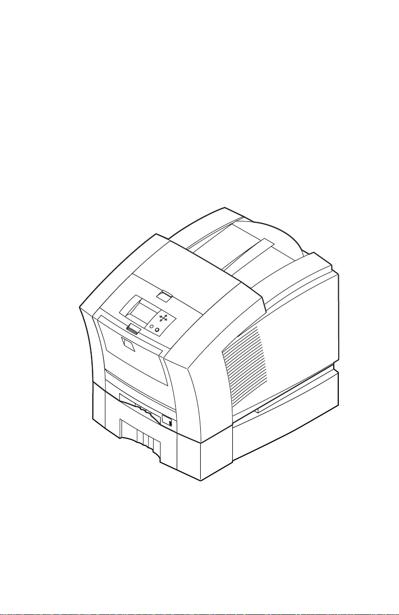
The Phaser 840 printer (shown with optional
High-capacity Paper Tray Assembly) 1
Internal features of the print engine 6
Circuit boards of the print engine (right front view) 7
Circuit boards of the print engine (left-rear view) 8
The printer’s I
Printhead maintenance system of the print engine 10
Sensors and switches on the right side of the print engine 11
Sensors and switches on the left side of the printer 12
Solenoids and clutches on the print engine 13
Features of the main board 14
Printer front panel 17
Printer rear panel 19
Attaching the service load connector to J250 41
Setting process belt tension 62
Setting exit roller drive belt tension 63
Setting the Y-axis belt tension 65
Attaching the digital gap indicator 66
Spacing the printhead to the drum 67
Aligning (timing) the cap/wipe/purge assembly drive belts 69
Setting the drum position encoder gap 71
Adjusting the transfix roller pressure springs 73
Adjusting the x-axis scale adjustment 74
Connecting the vacuum gauge to the printer 75
Resetting print engine NVRAM menu item 84
Clearing PostScript NVRAM menu item 85
Removing the main board 88
Removing the power supply 89
Removing the power control board 90
Removing the paper/drum heater 91
Remove the upper feed roller assembly (left side) 92
Removing the upper feed roller assembly (front) 93
Removing the drum transfix assembly (left side) 95
Removing the drum/transfix assembly (right side) 97
Marking the drum home flag sensor alignment 99
Removing the drum position sensor assembly 100
Plugging the reservoir holes 101
Removing the printhead 103
Removing the x-axis motor and drive assembly 104
2
C bus 9
viii
Phaser 840 Color Printer
Page 9

Removing the Y-axis belt drive assembly 105
Removing the cap/wipe/purge assembly 107
Cabinet FRUs 111
Imaging FRUs 113
Paper path FRUs 115
Motors and fans FRUs 117
Circuit boards FRUs 119
Solenoids and clutches FRUs 121
Gears and belts FRUs 123
Sensors and flags FRUs 125
High-capacity Paper Tray 127
Print engine wiring diagram 145
Wire routing on the right side of the printer near right I/O board 146
Wire dressing above the x-axis drive 147
Vacuum hose dressing 148
Routing wiring on the left side of the printer 149
Wire dressing behind the printhead 150
Service Guide
ix
Page 10

Tables
Installed RAM and printer capabilities 4
Tray switch sensor combinations 15
Rear panel DIP switch settings 19
Physical dimensions 20
Printer installation clearances 20
Functional specifications 21
Electrical specifications 22
Environmental specifications 23
Main board power-up self-test error codes 25
Front panel and fault history log error codes and messages 28
Motor and solenoid resistances 42
Hidden Service Menu 60
Cabinet FRUs 110
Imaging FRUs 112
Paper path FRUs 114
Motors and fans FRUs 116
Circuit board FRUs 118
Solenoid and clutches FRUs 120
Gears and belts FRUs 122
Sensors and flags FRUs 124
High-capacity Paper tray FRUs 126
Service tools 128
Supplies and accessories 128
x
Phaser 840 Color Printer
Page 11
General Information
This service guide contains information useful to verify operation, troubleshoot,
repair, adjust, and maintain a Tektronix Phaser® 840 Color Printer. This guide
includes a Field Replacement Unit list.
Topics such as printer theory of operation, detailed removal/replacement
procedures, configuration page details, and verifying printer operation are
located on the companion
To ensure complete understanding of the product, we recommend participation
in Phaser 840 printer service training, if available.
Color Printer Service & Support Resources CD-ROM
.
0388-01
The Phaser 840 printer (shown with optional High-capacity Paper Tray Assembly)
Service Guide
1
Page 12

Phaser 840 printer overview
The Phaser 840 Color Printer is an Adobe PostScript Level 3 (Version 3010) color,
solid ink-jet printer. It also supports color PCL 5C at 600 x 600 dots-per-inch
resolution. The Phaser 840 printer prints at a number of resolutions: A 10 pageper-minute (ppm) Fast Color Mode, a standard 5.7 ppm mode, an Enhanced
mode of 491 x 982 dpi at 3.3 ppm and a High-Resolution/Photo mode of 600 x
1200 dpi at 2.2 ppm.
All printer models but the standard version feature built-in auto-duplex printing.
Standard Phaser 840 printer .
and is equipped with 32 Mbytes of RAM. It can be upgraded to as much as
128 MBytes of RAM using any combination of two 16-, 32-, and 64-Mbyte RAM
DIMMs.
The Phaser 840 Plus printer.
printer to 64 Mbytes of RAM. It include a SCSI port daughter card to support an
external SCSI disk for additional font storage as well as a scanner. Special
circuitry on the SCSI port daughter card enables additional features like duplex
printing, job pipelining and Check Print mode. With job pipelining, the printer
can print one image and process the data for the next image at the same time.
Check Print mode prints the first page of a multiple page print job while holding
the remainder of the job pending front panel approval.
The Phaser 840 Extended printer.
of the Phaser 840 Plus printer but includes additional RAM to bring the printer to
128 Mbytes of RAM. It also includes a High-capacity Paper Tray and an internal
IDE hard drive.
All printers support four available paper trays: Two A and A4 trays are meant for
paper and low volumes of transparencies; two other A and A4 trays are meant for
label stock and high-volume transparencies. The optional 500-sheet Highcapacity Paper Tray Assemblies gives the printer a two-tray capability. With the
addition of a second High-capacity Paper Tray, the printer has a three tray
capability. (The High-capacity Paper Tray Assembly is sometimes referred to as a
lower feeder; it only supports paper printing.) The printer can also print six sizes
of handfed envelopes in low volumes.
A 133-MHz PowerPC processor oversees print engine operations and PostScript
image processing. The printer features an integral bi-directional parallel port
(IEEE 1284C with ECP mode) and a 10baseT Ethernet port (with support for
EtherTalk, Novell NetWare/NDS, TCP/IP, DHCP and Windows Peer-to-Peer).
A USB high-speed serial port is also provided. A rear panel slot allows
customers to install one “smart card” PhaserShare Series B Network Card. One
card provides a LocalTalk port. A second, alternative card offers a 10BaseT/
100BaseT/10Base2 Ethernet board providing standard protocol support for
EtherTalk, Novell NetWare/NDS, TCP/IP and DHCP. When installed, this card
disables the standard 10baseT port. A third card provides a Token Ring board
providing protocol support for TokenTalk, Novell NetWare/NDS and TCP/IP.
When inserted, this card also disables the standard 10baseT port.
The base Phaser 840 printer features 136 built-in fonts,
The Phaser 840 Plus printer option upgrades the
The Extended Features option has all the features
A second rear panel slot accommodates an internal IDE hard drive for print job
collation, job accounting, font storage and PDF direct printing.
2
Phaser 840 Color Printer
Page 13

The printer features Job Accounting, which maintains from 50 to 5000 records of
processed print jobs, depending on memory options and hard drive options. The
record contains information such as time and duration of the print and the
percentage of color coverage on the print. The log of records can be retrieved
using PhaserLink or PhaserShare.
Solid inks
Solid inks, sometimes called phase-change inks, are solid at room temperature
and are liquid at the higher temperature used during printing. The inks solidify
almost instantly after being jetted onto the printer’s drum. Because Tektronix'
proprietary solid inks bleed much less than ordinary liquid inks, they allow the
printer to print brilliant colors on plain paper. Each Tektronix solid-ink printer
inks are especially formulated for that printer; the inks are not interchangeable.
Note
Turning the printer off and allowing it to cool causes it to perform
a printhead cleaning and purge cycle upon power-up. The
printer's purge cycle consumes a significant amount of ink.
During normal use and servicing, turn the printer off and allow it
to cool only when necessary.
About RAM upgrades
The printer features two DIMM connectors which accept both 32-, or 64-Mbytes
RAM DIMMs (16-Mbyte RAM DIMMs work but are not offered). The printer can
use SDRAM DIMMs meeting these specifications:
■
168-pin DIMM
■
Synchronous DRAM
■
3.3 volts
■
10 nsec speed
■
Valid on-board Serial Presence Detect ROM
■
Unbuffered
■
Latency of 2
■
9 address columns
■
Maximum of 2.8 cm (1.1 in.) in height. SDRAM DIMMs from other
Phaser printers, such as the Phaser 740 and Phaser 780 color printers
may be too tall to fit inside a Phaser 840 printer.
Upon power-up, the image processor interrogates the 256 byte Serial Presence
Detect ROM, which describes the DIMM in great detail, such as data width, clock
delay, number of address columns and row, refresh rate and more. If the DIMM
does not meet the required specifications, it will be ignored; no error message will
be reported.
Service Guide
3
Page 14

Memory considerations
With more memory the printer dual frame buffers for printing one image while
processing a second image (which gives greater printing throughput). With
additional RAM memory, and the SCSI daughter card installed (the Plus and
Extended configurations), the printer’s capabilities increase as detailed in the
following table:
Installed RAM and printer capabilities
Feature Base (32 Mbytes) Plus configuration
Fast Color (draft)
printing
Standard Printing yes yes yes
Enhanced Printing yes yes yes
High-Resolution/
Photo Printing
Duplex printing no yes. The printer
Color PCL 5C yes yes yes
Pipelining no yes yes
Check Print no yes yes
Collation (requires
hard drive)
PDF printing.
Requires hard drive
Job accounting 50 records 500 records. 5000
Frame buffer (lower
print resolutions can
provide additional
frame buffer space)
yes yes yes
no yes yes
no yes yes
no Standard. Standard.
1 Letter size image 1 Letter-size image 2 Letter-size images
(64 Mbytes)
requires at least
80 Mbytes of RAM to
print duplexed, highresolution, 1200 x
600 dpi prints
records with optional
hard drive
Extended
configuration
(128 MBytes)
yes
5000 records with
included hard drive
4
Phaser 840 Color Printer
Page 15

Print the Configuration Page and check the item “Installed RAM” to see what
type of RAM is installed.
For example:
Installed RAM: 64 Mbytes
Mem slot 1: SDRAM/parity/64 MB/KMM366S823BTL-G0
Mem slot 2: empty
This is a list of SDRAM DIMMs that are branded for use by Tektronix in this
printer at the time this guide was published:
Size
32 Mbytes Samsung KMM366S403CTL-G0
32 Mbytes Samsung KMM366S403CTL-G0
32 Mbytes Micron MT166LSDT464Ag-66ZXX
64 Mbytes Samsung KMM366S823BTL-G0
64 Mbytes Micron/Crucial CT8M64S4D10-MBTBGLP
Maker Part Number
Service Guide
5
Page 16
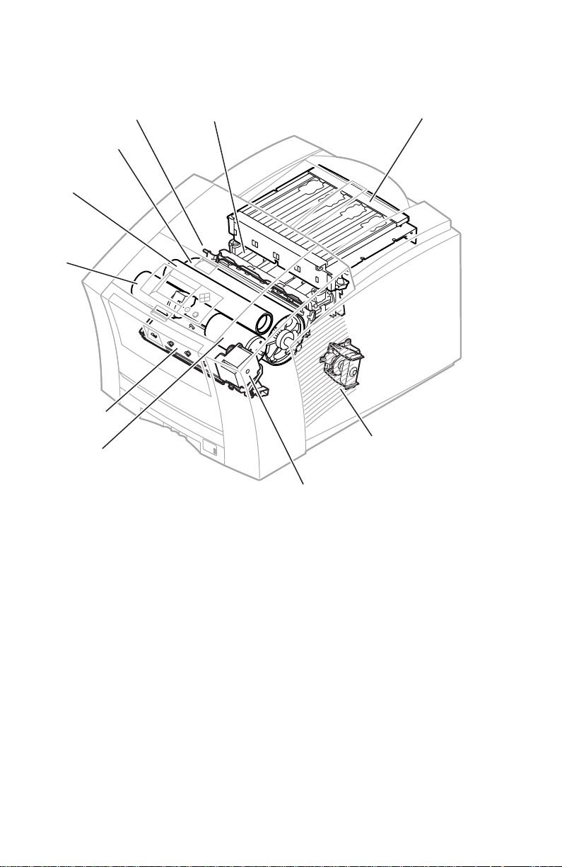
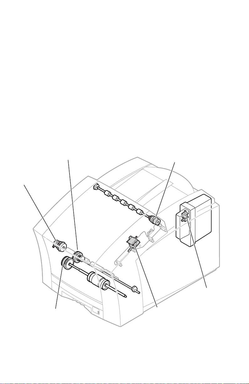
Print engine assemblies
2
Cap/wipe/purge
assembly
Drum
Transfix
roller
rocess
otor
Paper/
drum heater
Y-axis
motor
Printhead
Paper feed
motor
Ink load
assembly
X-axis drive
and motor
0388-0
Internal features of the print engine
6
Phaser 840 Color Printer
Page 17
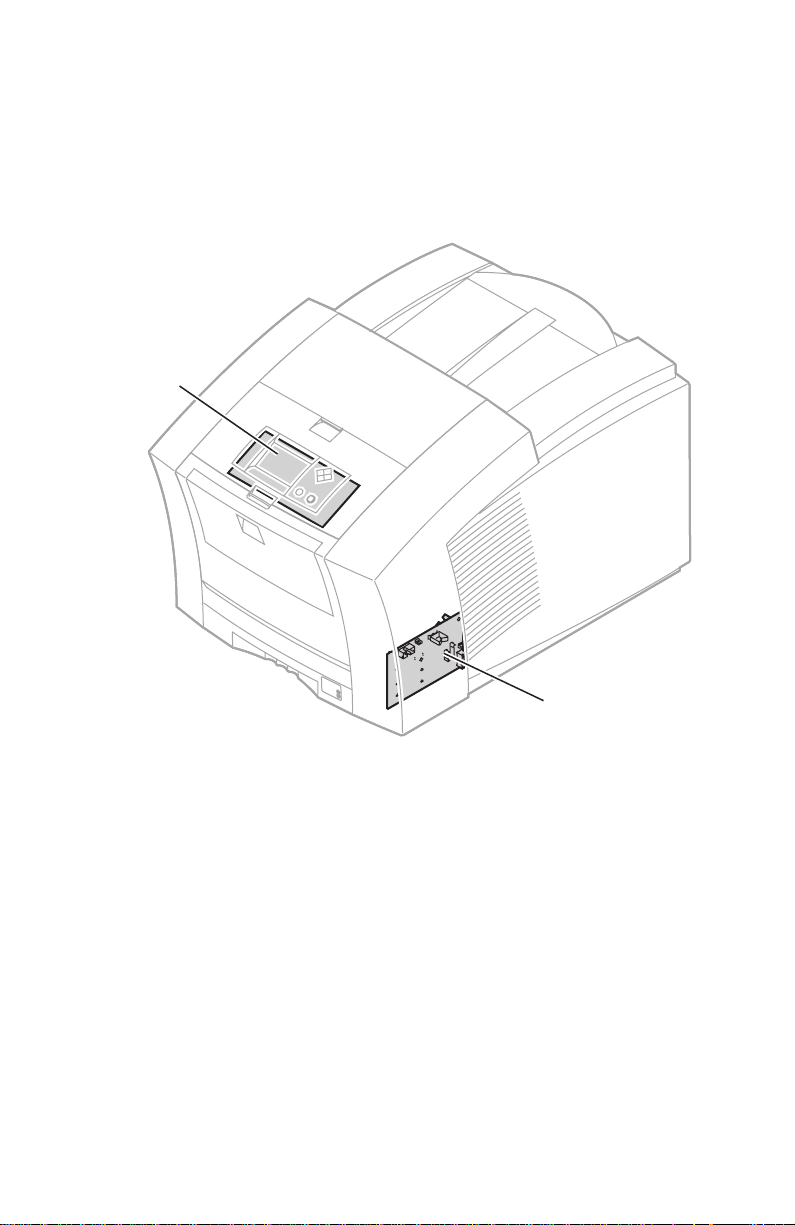
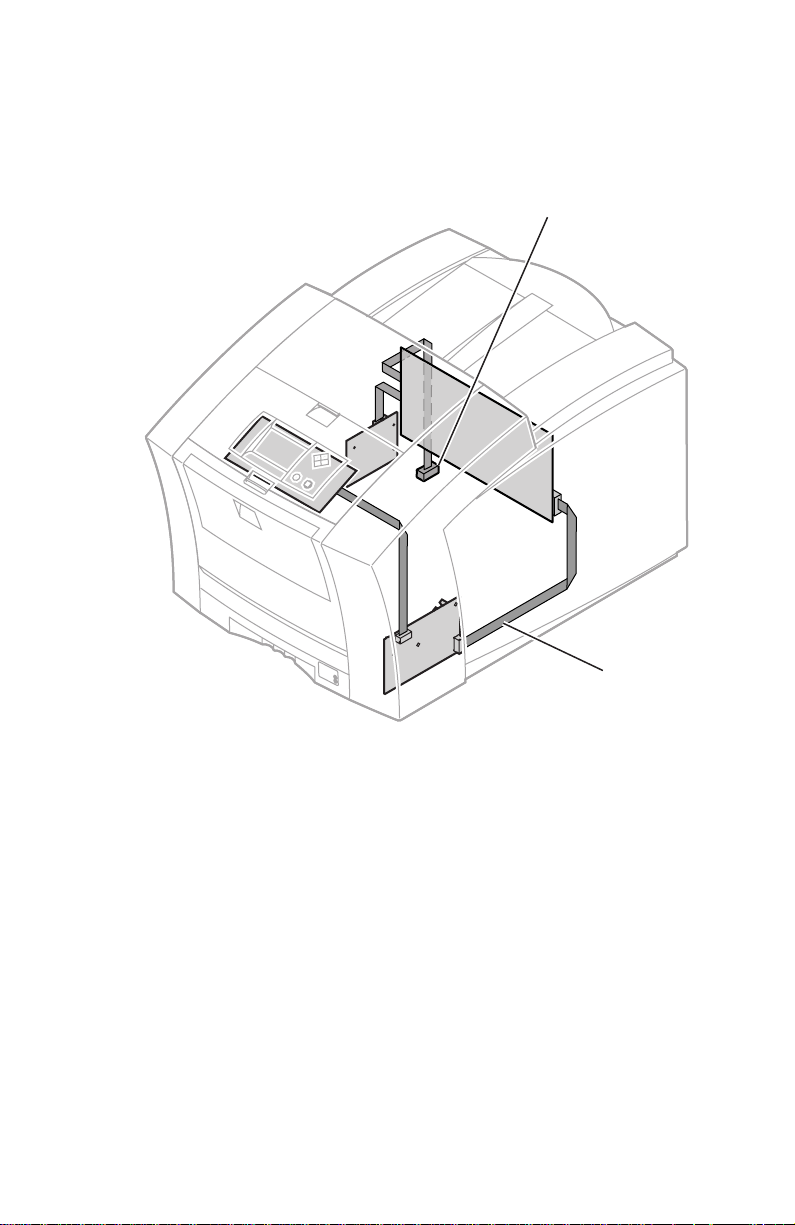
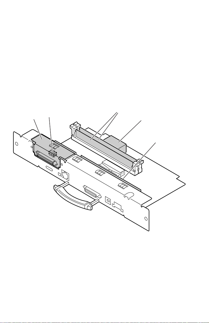
Six circuit boards support the printer’s electronics. Two boards, called I/
O boards, support the front panel, solenoids and sensors. The main board
contains the printer’s CPU processor, RAM and ROM. The power control board
distributes power supply voltages to the other printer boards as well as drive
many printer motors. The front panel provides a user interface to the printer. The
printhead drive board, a part of the printhead, manages the signals and voltages
of the printhead’s printing elements and sensors. The optional network card and
internal hard drive could be considered a seventh and eighth circuit boards.
Front
panel
Circuit boards of the print engine (right front view)
I/O board
right
Service Guide
0388-03
7
Page 18
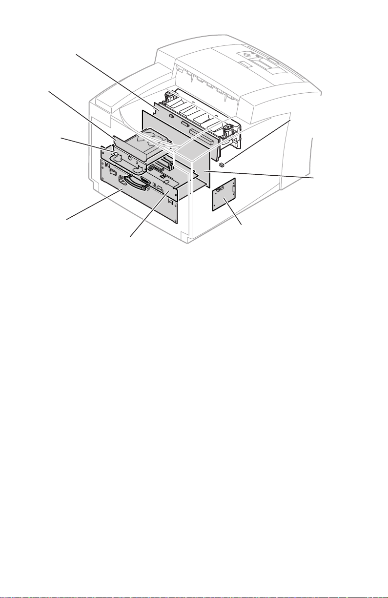
Printhead drive
board
Internal hard
drive
Network
card
Power
supply
Main board
Circuit boards of the print engine (left-rear view)
Drum
Maintenance
counter
EEPROM
Power
control
board
I/O board
left
0388-04
8
Phaser 840 Color Printer
Page 19
An internal data bus, called the I2C bus, connects all I/O boards to the main
board. Through this single bus, the main board can “poll” the I/O boards for the
state of the printer’s sensors as well as actuate the printer’s solenoids. This data
bus greatly simplifies the wiring that would otherwise be required for monitoring
numerous sensors and solenoids. The I
2
C bus also extends down to the High-
capacity Paper Trays.
High capacity
Paper T ray
connection
The printer’s I2C bus
Service Guide
I2C bus
0388-05
9
Page 20
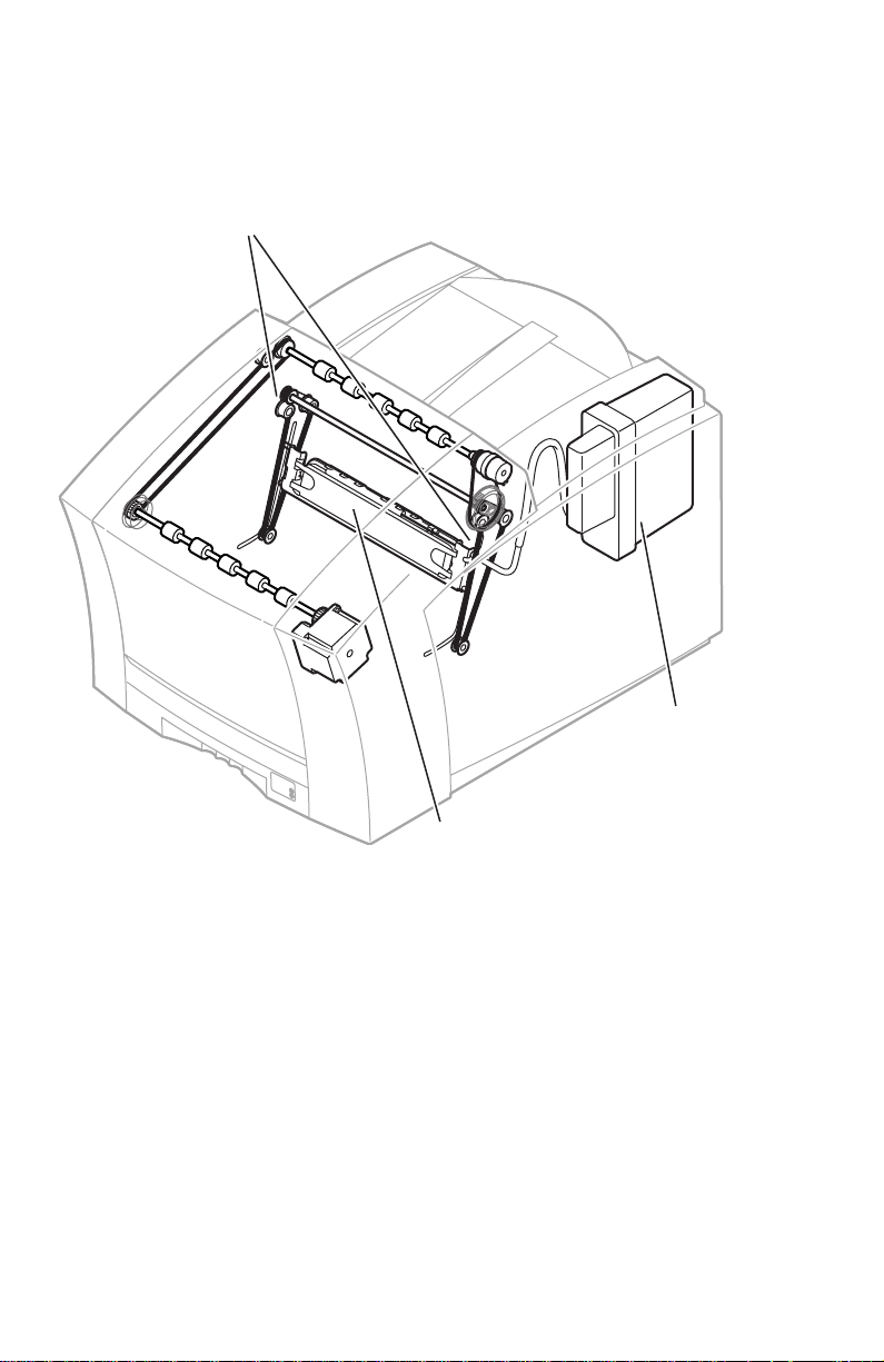
The printer features a printhead maintenance system used to clean the printhead
faceplate and clear clogs from the printhead nozzles. The system consists of a
vacuum pump assembly, the cap/wipe/purge assembly and the cap/wipe/
purge carriage drive.
Cap/wipe/purge
carriage drive
Cap/wipe/purge
assembly
Printhead maintenance system of the print engine
10
Phaser 840 Color Printer
Vacuum
pump
assembly
0388-06
Page 21
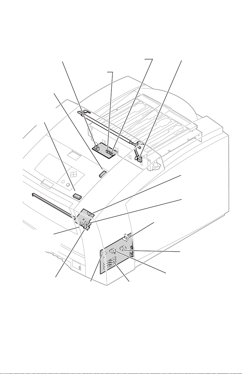
Sensors in the printer provide information to the main board to determine the
state of the printer. The printer monitors the positions of some of the movable
assemblies, such as the drum, as well as the temperature of many other
assemblies, such as the printhead, paper preheater and the drum.
Ink load
cover sensor
Top cover
switch
Front cover
switch
Preheater
entry/left
edge sensor
Ink-sticklow sensor
Ink-stickout sensor
Exit / tray-full
sensor
A4-size media
sensor
A-size media
sensor
Cap/wipe/purge
home sensor
Maintenance
blade position
sensor
Hand-feed
sensor
Paper-pick
sensor
Tray type
sensors
Paper-empty
sensor
Sensors and switches on the right side of the print engine
Service Guide
0388-07
11
Page 22
Transfix exit
sensor
Drum
temperature
sensor
Duplex
paper sensor
Drum-homeposition sensor
Drum encoder
sensor
Process
gear position
sensor
Preheater
exit sensor
Transfix
roller
Preheater
exit sensor
located on inside
wall of drum/transfix
frame
Drum
Sensors and switches on the left side of the printer
12
Phaser 840 Color Printer
Preheater
0388-34
Page 23
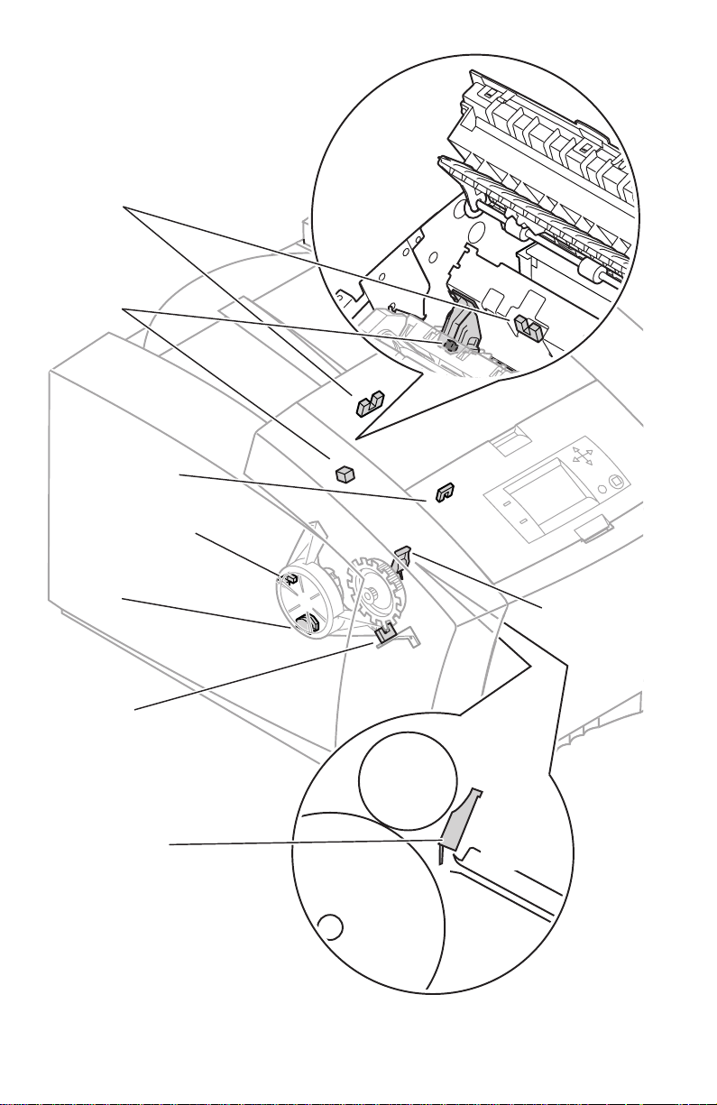
Caution
8
Electric clutches and solenoids are used by the printer to engage rollers as needed
to move paper through the printer as well as start some print processes.
The actual position of some printer assemblies, such as the
printhead or the cap/wipe/purge assembly, cannot be ascertained
at all times. The printer records, in NVRAM, where it last
positioned such assemblies each time it moves them. If, after
power-down or a power interruption, the assemblies are manually
repositioned, the printer erroneously assumes that the assemblies
are in the position it last left them. This assumption can result in
damage to the printer when it tries to position the assemblies. For
example, the printhead could be tilted forward and crash into the
raised cap/wipe/purge assembly.
Before turning on the printer, ensure the printhead is tilted
forward, centered in front of the drum and the cap/wipe/purge
assembly is in the retracted, home position. The tilt cam gear
should be disengaged from the gear drive train.
Upper feed
roller clutch
Pick clutch
Drum maintenance
cam clutch
Cap/wipe/purge
clutch
Air valve
solenoid
Transfix
solenoid
Solenoids and clutches on the print engine
Service Guide
0388-0
13
Page 24
The main board
The main board features the printer’s PowerPC processor that controls the engine
and the PostScript processing. Prominent on the main board is the ROM code
DIMM and the RAM DIMM plug-in modules. The code ROM DIMM also
contains the printer’s on-board fonts. Variations of the ROM code DIMM contain
alternate language fonts such as Kanji or Hangul.
Network connection is provided through a built-in 10baseT port. A plug-in SCSI
interface adaptor board provides a SCSI port for an external hard drive or
scanner.
The printer stores unique printer status and PostScript values in its NVRAM
module. The printer’s Ethernet address, unique to each printer, is stored in the
printer ID chip, an 8-pin socketed IC. All these socketed components should be
transferred to a replacement main board to maintain customer-unique settings.
SCSI riser
board
Boot ROM/
Printer ID
Features of the main board
RAM DIMMs
NV RAM/
Real Time Clock
Code ROM
DIMM
0388-09
14
Phaser 840 Color Printer
Page 25

Combination sensors and their meanings
Combinations of sensors are used by the printer to determine the type of standard
(or upper) media tray installed in the printer.
Media tray type sensing
The combinations of the three tray sensors inform the print engine what type of
media tray is installed. (The print engine does not detect the type of media
installed in the tray; it only detects the particular tray being used by the presence
of sensor flags on the side of the tray.) The tray sensors are located on the
right-side interior of the paper tray slot, mounted on I/O board right. There are
four tray types:
■
Letter (A-size).
low-volumes of A-size transparency film.
■
Metric Letter (A4-size).
paper as well as low-volumes of A4-size transparency film.
■
High-volume Transparency/Label (A).
volumes of U.S.-size transparency film as well as laser quality, adhesive
label stock.
■
High-volume Transparency/Label (A4).
volumes of Metric-size transparency film as well as laser quality,
adhesive label stock.
Table 1 Tray switch sensor combinations
This tray is sized for 8.5 x 11-inch (U.S.) paper as well as
This tray is used for 210 x 297 mm (Metric)
This tray supports high
This tray supports high
Tray type A Paper A4 Paper A Transparency A4 Transparency
Top switch Closed Open Closed Open
Middle switch Open Closed Open Closed
Bottom switc
h Open Open Closed Closed
Service Guide
15
Page 26

Front panel
These front panel features are found on the printer:
■
128 x 64 pixel backlit graphic display
■
Two push buttons and four arrow buttons
■
Two LEDs
LCD.
The backlit LCD serves two purposes: displaying current image processor
and print engine status information and displaying an interactive menu. Status
information includes image processor status such as
Receiving data
Out of paper, Paper Jam, Add ink
Customers can review and modify certain NVRAM, I/O ports and peripheral
parameters. Using the front panel to review and change parameters is discussed
in the topic, “Adjustments” on page 59.
and
Printing
. Print engine status includes messages such as
as well as error messages.
Ready to print
,
Buttons.
other two buttons are used as Select and Help.
In addition, when in the troubleshooting menu, pressing the
Select
Pressing and holding the
immediately to the language selection menu.
Holding the
correctly parked by flashing both front panel LEDs.
Turning the printer on with the rear panel DIP 2 in the “down” position, allows
access to the front panel during the warm-up cycle.
Four of the six buttons are arranged as a diamond-shaped keypad. The
button enters the hidden service support menu.
Left arrow
Right arrow
while turning off the printer will confirm the printhead is
and the
Select
button proceeds
Left arrow
and the
16
Phaser 840 Color Printer
Page 27
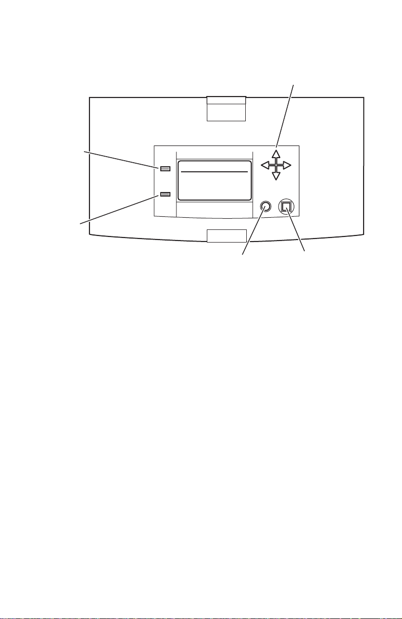
The topic “Resetting NVRAM” on page 83 explains how to use the front panel
buttons to reset the NVRAM to its factory-default values.
Navigation
buttons
Power
READY TO PRINT
Error
Printer front panel
Help
button
Select
button
0388-10
Service Guide
17
Page 28

Rear panel
Connectors
The rear panel of the printer features the host interface connectors to the printer; it
includes the following connectors:
■
Standard parallel (high-density connector), IEEE 1284C
■
Twisted Pair (10BaseT) Ethernet connector
■
A Universal Serial Bus port
■
Optional SCSI high-density connector (hard disk drive or Tektronix
approved scanner).
■
A special 5-pin connector accommodates a service RS-232 cable from a
PC or Macintosh computer running PC-based diagnostics.
The rear panel also includes two option slots. With the addition of a PhaserShare
network card in one slot, the printer can feature either of these connector
combinations:
■
LocalTalk connector
■
ThinNet (10Base2) and Twisted Pair (100BaseT) Ethernet or Token Ring
connectors.
Note
When an Ethernet or TokenRing PhaserShare card is installed,
the printer’s built-in 10BaseT Ethernet port is disabled.
The second slot accommodates an internal IDE hard drive for print job collation,
job accounting, font storage and PDF direct printing.
Health LEDs
Two health LEDs indicate the status of the printer’s CPU functions: PostScript
processing and print engine control.
■
Blinking
: The printer is operating normally. Both LEDs blink
irregularly during diagnostics.
If a soft error occurs, image processing occurs, but in a reduced capacity.
Soft failures include failure of expansion memory DIMMs or any of the
interface ports. When a soft error occurs, the printer automatically
prints a startup page listing the error.
■
On
or
Off, or blinking a coded error indication
: A hard error condition has
occurred that would keep the image processor board from operating.
Refer to the topic “Error Codes and Messages” on page 25 for the
meaning of a coded indication.
18
Phaser 840 Color Printer
Page 29
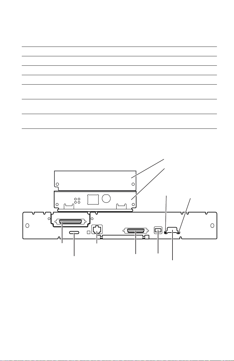
Switches
Four DIP switches allow you to reset the printer or place the printer in different
operating modes.
Table 2 Rear panel DIP switch settings
Function Switch 1 Switch 2 Switch 3 Switch 4
Normal operating mode UP UP UP UP
Service mode DOWN UP UP UP
Reset printer UP UP UP DOWN
Manufacturing mode (Bypass
UP DOWN UP UP
mode)
Development mode (engineering
DOWN DOWN DOWN UP
use only)
Recovery mode (engineering use
DOWN UP DOWN UP
only)
The following figure illustrates the rear panel of the printer.
IDE hard drive
Network card
PostScript
PhaserShare
Series B
Ethernet Card
health
TM
100
Mbs
TX
RX
TP
LINK
10/100Base-TX
10Base2
light
Engine
health
light
SCSI
Service
RS-232
Printer rear panel
Ethernet
10BaseT
Parallel
USB
DIP
switches
Service Guide
0388-11
19
Page 30

Physical dimensions
Dimensions Value
Height: 38.7 cm. (15.25 ins.)
Width: 40 cm (17.25 ins.)
Depth: 57.8 cm (22.75 ins.)
Weight: Approximately 36 kgs (79 lbs). Print engine weight only;
51.4 cm (20.25 ins.) with one High-capacity Paper Tray
Assembly
64.1 cm (25.25 ins.) with two High-capacity Paper Tray
Assemblies
add 9 kgs (20 lbs.) for each optional High-capacity Paper
Tray Assembly.
Printer installation clearances
Clearances Value
Top: 45.7 cm (18 ins.)
Left: 10.2 cm (4 ins.)
Right: 10.2 cm (4 ins.)
Front: Unrestricted to replace trays and clear paper jams
Rear: 10.2 cm (4 ins.)
Bottom: No obstruction under printer that could block its cooling
vents.
Mounting surface
flatness:
20
Phaser 840 Color Printer
Within 3 degrees of horizontal with all four feet in contact with
the surface.
Page 31

Functional specifications
Characteristic Specification
Printing process Solid ink-jet onto plain paper.
Color medium Cyan, magenta, yellow and black ink sticks, each shape-
coded. The printer uses the subtractive color system to
produce the colors red, green, and blue.
Addressability Selectable 273 x 300, 409 x 409, 491 x 982 or 600 x 1200
dots-per-inch (horizontal and vertical).
Engine printing
speed (single-sided)
The time it takes from loading to ejecting:
Fast Color 273 x 300 dot per inch:
on A- or A4-size: ≈ 6 seconds per print
Standard 409 x 409 dpi:
on A- or A4-size: ≈ 10.5 seconds per print
Enhanced 491 x 982 dpi:
on A- or A4-size: ≈ 18 seconds per print
Photo 600 x 1200 dpi:
on A- or A4-size: ≈ 24 seconds per print
Fast Transparency film (273 x 300 dpi):
on A- or A4-size: ≈ 12 seconds per print
Standard Transparency film 409 x 409 dpi):
on A- or A4-size: ≈ 22 seconds per print
Print times do not include image processing time, which
varies, due to image complexity. 25 mm (1 in.) margins
assumed with 35% ink coverage.
Minimum printing
All sides: 5 mm (0.2 in.)
margins
Maximum print area A-size: 8.1 x 10.6 in.
A4-size: 200 x 283 mm
Usable paper
weights
Tray fed: 16 - 32 lb. Bond (60 - 120 g/m
65 lb. (176 g/m
2
) Cover stock (main tray only)
Manual fed: 16 - 32 lb. Bond (60 - 120 g/m
50 - 80 lb. Cover (135 - 220 g/m
110 lb (216 g/m
2
) Index stock
2
)
2
)
2
) -single-sided
Usable envelopes #10 (U.S.)
#6 3/4 (U.S.)
C5 (Metric)
DL (Metric)
Choukei 3 Gou
Choukei 4 Gou
Do not use envelopes with endflaps, plastic windows or
metal clasps; they can damage the printer.
Label A/A4 laser quality sheet stock only, Recommended Avery™
white laser labels:
U.S.: 5160, 5960
Metric: L7162
Service Guide
21
Page 32

Electrical specifications
Characteristic Specification
Primary line voltages 87 to 132 VAC (115 VAC nominal)
174 to 264 VAC (220 VAC nominal)
Input voltage range is auto-sensed.
Primary voltage
47 to 63 Hz
frequency range
Power consumption 200 watts standby; 300 watts at idle; 600 watts during
printing. Maximum power consumption 1000 watts during
warm-up.
Current rating 115 VAC configuration – 8 amp max./1 amp min.
220 VAC configuration – 4 amp max./1 amp min.
Fusing F1: DC switcher - 6.3 amp slo-blo
F2: Drum heater 1, reservoir heater 1, ink melt chambers,
cap/wipe/purge unit - 10 amp slo-blo
F3: Jet stack left and right, paper pre-heaters, reservoir
heaters 2,3,and 4 10 amp slo blo
Fuses are not user-accessible.
Secondary voltages +5
V ± 2.5%
+12 V ± 5%
-12 V ± 5%
+40 V -5%, +12%
-52 V ± 10%
+54 V ± 10%
RF emissions Both 115 and 220 VAC-configured instruments pass these
standards:
EC EN60950:1992 Safety of Information Technology
Equipment including Business Equipment
EC EN55022:1992 Limits and methods of measurement of
radio interference characteristic of Information Technology
Equipment
EC EN50082-1:1997 The Generic Immunity Standard
Residential, Commercial, and Light Industry
EN61000-4-3:1995-02 RF Field Immunity
EN61000-4-2:1995-01 ESD (Electo-Static Discharge)
EN61000-4-4:1995-01 Fast Burst Transient
EN61000-4-5:1995-02 Line Surge
EN61000-4-6:1996-03 RF conducted Immunity
EN61000-4-11:1994-06 Voltage Dips and Interruptions
EN61000-3-3:1994-12 Flicker
73/23/EEC Low Voltage Directive
89/336/EEC Electromagnetic Compatibility Directive
89/392/EEC Machinery Directive
22
Phaser 840 Color Printer
Page 33

Environmental specifications
Characteristic Specification
Temperature
Operating
Storage and
shipping
Humidity
Operating
Non-operating
Altitude
Operating
Non-operating
Vibration/shock
Non-Operating
(vibration)
Non-operating
(shock)
Operating (shock)
10 to 32 C
-30 to 60
°
(50 to 90° F)
°
C (-22 to 140° F)
10 to 80% relative humidity, non-condensing
10 to 95% relative humidity, non-condensing
0 to 2400 m (8,000 ft.) at 25
°
C
0 to 15000 m (50,000 ft.)
Will withstand 0.15 G excitation, 5 to 200 Hz, 3 axes for up to
7 minutes with no impairment or subsequent damage.
0.5 g, 25 minute sweep, 5-200-5 Hz, 100-200 sec/sweep
cycles
The printer may have any corner raised and dropped 1.5 cm
(0.6 in.) while printing is in progress, without impairment of
operation that cannot be recovered by a printhead purge
cycle. The printer may have any corner raised and dropped
6 cm (2.4 in.) while idle without subsequent impairment of
operation.
Service Guide
23
Page 34

Regulatory specifications
The Phaser 840 Color Printer is in conformance with the following regulatory
standards:
■ FCC Part 15 Class B (for 115 VAC equipment)
■ EN55022 (CISPR 22) Class B
■ VCCI (CISPR 22) Class B
■ EN61000-3-2 Flicker on AC Mains Susceptibility
■ The packaged product meets National Safe Transit Committee Test
Procedures
Listed:
■ UL 1950 Information Technology Equipment
Certified to:
■ CSA C22.2 No. 950 Safety of Information Technology Equipment,
Including Electrical Business Equipment
GS licensed:
■ IEC 950 (1991) Second Edition; EN60950 Information Technology
Equipment
24
Phaser 840 Color Printer
Page 35

Error Codes and
Messages
Rear panel LEDs error codes
The rear panel LEDs are located on each side of the rear panel DIP switches.
left LED represents the operation of the PostScript firmware. The right LED represents
operation of the main board’s print engine firmware.
LEDs toggle back and forth for each successful pass through each SDRAM test. A
failure in the power on self tests is indicated by the left LED (the PS LED) flashing
in a specific pattern of long and/or short flashes and repeated indefinitely. A long
flash represents a 5, while a short flash is a 1. For example, a long flash followed
by 4 short flashes is 5 + 4 = 9. If the left LED repeatedly flashes in the same
sequence, then the PostScript processor has encountered an error and is looping.
The possible LED-encoded error codes are listed in the following table. Other
failures are indicated by the failure being printed on the Startup Page.
After successful power-up, the left LED flashes at a regular “heartbeat” rate. The
Power
front panel
cleared.
Table 3 Main board power-up self-test error codes
Left LED
flashes
Long flash =5
Short flash=1
2L+1S=11
1
2 SDRAM
light is turned on, the
Meaning Details
not used
SIMM
Presence
This test verifies for the presence of both SDRAM
SIMMs. If both SDRAM SIMMs are missing the
resultant error indication is 2 short flashes from the
left LED.
During the POST tests, the two
Error
light is flashed, and the LCD is
The
3 SDRAM bank 0This test verifies DRAM bank 0 in the DRAM DIMM
4 SDRAM bank 1This test verifies DRAM bank 1 in the DRAM DIMM
5 SDRAM bank 2This test verifies DRAM bank 0 in the DRAM DIMM
6 SDRAM bank 3This test verifies DRAM bank 1 in the DRAM DIMM
7 not used
8
not used
located in Position 0 (closest to the rear panel)
located in Position 0 (closest to the rear panel)
located in Position 1 (farthest from the rear panel)
located in Position 1 (farthest from the rear panel)
Service Guide
25
Page 36

Table 3 Main board power-up self-test error codes
Left LED
Meaning Details
flashes
Long flash =5
Short flash=1
2L+1S=11
9 NVRAM This test does a w alking 1s and a walking 0s test for
that last 4 bytes in the VxWorks section of the
NVRAM.
10 EPROM This test reads in the first 24 bytes from the EPROM
then verifies that the Tektronix Ethernet address
0x08, 0x00, and 0x11 has been copied into three
locations.
11 Mariner ASIC This test reads and verifies the version level of the
Mariner ASIC.
12 Medusa ASIC This tests reads and verifies the version level of the
Medusa ASIC.
13 Super Glue
ASIC
This tests reads and verifies the version level of the
Super Glue ASIC.
14 CL1284 IC This tests reads and verifies the version level of the
parallel port controller CL1284 chip.
none
SCSI This test verifies the functionality of the SCSI I/O
processor. Any test failures with this component are
treated as non-fatal errors with the error information
written to the Start Page. If a failure is detected, the
message “SCSI Option Card:” with one of the
following messages will be sent to the Start Page.
■
Wrong values in script-set scratch registers.
Script operation timed-out.
■
■
Script operation returns wrong exit code.
■
DMA transfer spills outside buffer.
DMA transfer data mismatch.
■
none
10baseT This test verifies the functionality of the Ethernet
LAN Controller chip. Any test failures with this
component are treated as non-fatal errors with the
error information written to the start page. If a failure
is detected, the message “Ethernet:” with one of the
following messages will be sent to the start page.
■
General Failure.
MAC internal loopback failure.
■
■
MII internal loopback failure (currently disabled)
26
Phaser 840 Color Printer
Page 37

Table 3 Main board power-up self-test error codes
Left LED
flashes
Long flash =5
Short flash=1
2L+1S=11
none
none
none
Meaning Details
Ethernet
100BaseT
Option Card
This test verifies the functionality of the Ethernet
LAN Controller chip. Any test failures with this
component are treated as non-fatal errors with the
error information written to the Start Page. If a f ailure
is detected, the message “Ethernet Option Card:
with one of the following messages will be sent to
the Start Page.
General Failure.
■
■
MAC internal loopback failure.
MII internal loopback failure.
■
Token Ring
Option Card
This test verifies the functionality of the processor
chip. Any test failures with this component are
treated as non-fatal errors with the error information
written to the Start Page.If a failure is detected, the
message “Token Ring Option Card:” with one of the
following messages will be sent to the Start Page.
■
General error
■
Problem with EEPROM
Error trying to Bring Up Diags
■
■
Error initializing device
Command completion error
■
■
Interrupt error
■
Wrong vendor ID
■
Wrong microcode version
Wrong version ID
■
LocalTalk
Option Card
This test verifies the functionality of the LocalTalk
option card. Any test failures with this component
are treated as non-fatal errors with the error
information written to the Start Page. If a failure is
detected, the message
General Error
LocalTalk Option Card:
will be sent to the Start Page.
Service Guide
27
Page 38

Error messages
Error codes indicate the following:
■
The failing system (XX,yyy.zz)
■
The failing subsystem (xx,
■
The actual problem (xx,yyy.ZZ).
■
The print engine copy count (xx,yyy.zz
Table 4 Front panel and fault history log error codes and messages
Error code Meaning
2,000: System fault I/O board...
YYY
.zz)
:123
) the error occurred on.
2,001.40:
SY_DEV_FAULT_IO_
RIGHT
2,002.40:
SY_DEV_FAULT_IO_
LEFT
4,000: PC (process control supervisor)....
4,001.40 (0x2401):
PC_DEV_FAULT_HEAD
_READ
4,002.41 (0x2402):
PC_DEV_FAULT_HEAD
_ZEROS
4,003.42 (0x2403):
PC_DEV_FAULT_HEAD
_ONES
4,004.43 (0x2404):
PC_DEV_FAULT_HEAD
_CHECKSUM
4,005.44 (0x2405):
PC_DEV_FAULT_DM_
CAM_ERR
4,009.48 (0x2409)
PC_DEV_FAULT_DM_
CAM_BEGIN
The engine can not detect the presence of the right I/O
board. Ensure the connections are good.
The engine can not detect the presence of the left I/O
board. Ensure the connections are good.
Failure reading printhead NVRAM data: chec k the wiring
to the printhead, I2C bus and other hardware.
Printhead NVRAM data was all zeros: has this printhead
been through normalization? If so, check wiring to
printhead.
Printhead NVRAM data was all ones: has this printhead
been through normalization? If so, check the wiring to the
printhead.
Printhead NVRAM checksum failure: the data within the
printhead NVRAM has been corrupted. Check the
hardware and wiring. The printhead may need to be
renormalized (a manufacturing function).
Failure positioning drum maintenance cam during a drum
maintenance cycle: check drum maintenance cam
solenoid, clutch, home sensor, and related hardware.
At the start of a drum maintenance cycle, when the drum
maintenance cam position should have been at blade
down, oil roller down, the drum maintenance cam home
sensor should have been TRUE and was instead FALSE.
Check the drum maintenance cam solenoid, clutch, home
sensor, and related hardware.
28
Phaser 840 Color Printer
Page 39

Table 4 Front panel and fault history log error codes and messages
Error code Meaning
4,010.40 (0x240A)
PC_DEV_FAULT_DM_
CAM_BU_WU
4,011.41 (0x240B)
PC_DEV_FAULT_DM_
CAM_BU_WD
4,012.42 (0x240C)
PC_DEV_FAULT_DM_
CAM_END
4,013.43 (0x240D)
PC_DEV_FAULT_GEAR
_GRIND
During the drum maintenance cycle, when the drum
maintenance cam position should have been at blade
up/oil roller up, the drum maintenance cam home sensor
should have been FALSE and was instead TRUE. Check
the drum maintenance cam solenoid, clutch, home
sensor, and related hardware.
During the drum maintenance cycle, when the drum
maintenance cam position should have been at blade
up/oil roller down, the drum maintenance cam home
sensor should have been FALSE and was instead TRUE.
Check the drum maintenance cam solenoid, clutch, home
sensor, and related hardware.
At the end of a drum maintenance cycle, when the drum
maintenance cam position should have been at blade
down/oil roller down, the drum maintenance cam home
sensor should have been TRUE and was instead FALSE.
Check the drum maintenance cam solenoid, clutch, home
sensor, and related hardware.
During power-on initialization, the engine is unable to
disengage the process motor. Prior to declaring this fault,
the engine has attempted to move the process motor
through enough revolutions to disengage the head tilt
mechanism, but the motor stalled. The X-axis was then
displaced to the right 3.8 mm (0.15 in.) and the disengage
was repeated, but the motor stalled again. This fault is
then declared. The head is unable to move on its tilt axis,
perhaps because it is colliding with something (head
restraint pin, cap, poorly installed ink loader, screwdriver.)
4,014.44 (0x240e)
PC_DEV_FAULT_6x6DP
I_CAL
4,015.45 (0x240F)
PC_DEV_FAULT_HEAD
_
ADJUST_TIMEOUT
4,016.46 (0x2410)
PC_DEV_FAULT_HEAD
_NV_FORMAT
4,016.68 Bad Message in main pc_ready message loop . The code
Calibration Failure: Defined but not used.
The engine spent too much time in the printhead
adjust-state. The engine declares a device f ault and shuts
down, rather than leave a hot heater against a cold drum
for an indefinite period.
The printhead format number, stored in printhead
NVRAM, is not understood by this version of engine
firmware.
received an unexpected message while the printer was in
ready state waiting for a command from PostScript.
Typically this message is a PM_RESULT_OK message
that is the result of a previous command to PM to tilt the
head back. The odd behavior is that PC is not waiting for
the operation to finish.
Service Guide
29
Page 40

Table 4 Front panel and fault history log error codes and messages
Error code Meaning
4,017.47 (0x2411)
PC_DEV_FAULT_
AMBIENT_TOO_COLD
4,018.48 (0x2412)
PC_DEV_FAULT_LATE_
CLEAN_REQUEST
4,019.40 (0x2413)
PC_DEV_FAULT_
193DPI_CAL
4,020.41
PC_DEV_FAULT_FTTR
_HEADCAP
04,021.4x
PC_DEV_FAULT_FTTR
_DIRTYDRUM
4,023.66 Cannot tilt head forward. The engine was attempting to
5,000: Y axis (drum)
Ambient temperature has fallen to less than 10o C.
Something may be wrong with a heater.
After the printer determined, at power-up, that the
printhead was warm enough not to need cleaning, and
while the printer was warming up, the printhead
temperature dropped below the head-clean-needed
threshold. Something may be wrong with a heater.
Calibration Failure: Target Volt-Sec Area of Fast Color
mode could not be achieved. Check the hardware. The
head may need to be renormalized.
Declared when the printer is booted and the head/cap
contact flag is set in NVRAM. The printer cannot run with
the head and cap/wipe/purge unit in contact because it
would be unwise to separate the two when the printhead
is cold.
Declared when the printer is booted and the drum is dirty.
Cleaning the drum when very cold could increase the
chance of gluing media to the drum surface and creating a
mess around the stripper fingers.
do something that required the printhead to be in print
position. The printhead was not in position and some
condition was preventing the code from tilting it.
5,001.41 (0x2c01)
YA_HOME_FAIL
5,002.41 (0x2b02):
YA_STALL_FAIL
5,002.42 (0x2b03):
YA_POS_FAIL
6,000: X axis
6,000.41 (0x3400):
XA_FAULT_MCURRENT
7,000: Process motor
30
Phaser 840 Color Printer
Drum-home sensor failure: the drum turned one full
revolution without seeing the drum home sensor activate .
Check the drum-home sensor or I/O board 1.
The Y-axis (drum) motor stalled, possibly because the
drum position sensor electronics have failed, or because
the motor drive or drive belts have failed, or because
something is physically blocking the motion of the drum.
Y-axis position failure, the drum is not where is should be,
possibly because the drum position sensor electronics
have f ailed, or because the motor drive or drive belts ha v e
failed, or because something is physically blocking the
motion of the drum.
X axis motor over/under current. Indicates motor coil(s)
are open, or shorted, or the motor fuse has opened.
Page 41

Table 4 Front panel and fault history log error codes and messages
Error code Meaning
7,001.43 (0x3c01):
PM_FAULT_AUXILIARY
_
MOTOR_ERROR
7,002.44 (0x3c02):
PM_FAULT_PROCESS_
MOTOR_STALL
7,003.45 (0x3c03):
PM_FAULT_
COMPOUND_
GEAR_SENSOR_BAD
7,004.46 (0x3c04):
PM_FAULT_DM_CAM_
SENSOR_BAD
8,000: Cap drive and web sensors
8,001.44 (0x4401):
CAP_FAULT_HOME_
SENSOR
8,002.46
CAP_FAULT_
OVERCURRENT
9,000: Ink loader: ink melters and printhead ink level sensors.
9,001.45 (0x4c01):
IL_FAULT_C_
TWANGER
The electronics report an error while operating the motor
in the auxiliary feeder (the optional High-capacity paper
Tray)
The process motor stalled during operation. This has
several possible causes, depending on what the process
motor was gear-connected to at the time of failure.
No transitions are observed of the compound gear sensor
when the compound gear should be turning. P erhaps the
sensor is failing, or the process motor to compound gear
linkage is broken.
No transitions are observed of the drum maintenance
cam sensor. The sensor may be failing or the drum
maintenance cam may be jammed.
An expected transition of the cap-home sensor did not
occur. The home sensor may be faulty, or the cap motor
may not be operating, or the cap may be jammed and
unable to move.
The cap/wipe/purge assembly stalled: Defined but not
used.
Malfunction of the ink-level sensor in the cyan reservoir.
Replace the printhead.
9,002.46 (0x4c02):
IL_FAULT_M_
TWANGER
9,003.47 (0x4c03):
IL_FAULT_Y_
TWANGER
9,004.48 (0x4c04):
IL_FAULT_K_
TWANGER
9,005.40 (0x4c05):
IL_FAULT_C_JAM
Malfunction of the ink-level sensor in the magenta
reservoir. Replace the printhead.
Malfunction of the ink-level sensor in the y ellow reservoir.
Replace the printhead.
Malfunction of the ink-level sensor in the black reservoir.
Replace the printhead.
The cyan ink-melt heater is on, but ink does not seem to
be dripping. Check that the ink stick is able to advance in
the chute. An ink stick jam will be reported three times
before an ink-melter fault is declared.
Service Guide
31
Page 42

Table 4 Front panel and fault history log error codes and messages
Error code Meaning
9,006.41 (0x4c06):
IL_FAULT_M_JAM
9,007.42 (0x4c07):
IL_FAULT_Y_JAM
9,008.43 (0x4c08):
IL_FAULT_K_JAM
11,000:DMC
11,011.61 DMC event parameter block not found. The DMC library
11,020.61 DMC event parameter block not found. The DMC library
13,000:Printhead thermals
13,001.40 (0x6c01):
TCH_JS_LEFT_OPEN
13,002.41 (0x6c02):
TCH_JS_LEFT_SHORT
The magenta ink-melt heater is on, but ink does not seem
to be dripping. Check that the ink stic k is able to advance
in the chute. An ink stic k jam will be reported three times
before an ink-melter fault is declared.
The yellow ink-melt heater is on, but ink does not seem to
be dripping. Check that the ink stick is able to advance in
the chute. An ink stick jam will be reported three times
before an ink-melter fault is declared.
The black ink-melt heater is on, but ink does not seem to
be dripping. Check that the ink stick is able to advance in
the chute. An ink stick jam will be reported three times
before an ink-melter fault is declared.
was attempting to locate an event parameter block in its
linked list. The block was not found.
was attempting to locate a timer parameter block in its
linked list. The block was not found.
The thermistor in the left jet stack appears to be open.
Replace the printhead.
The thermistor in the left jet stack appears to be shorted.
Replace the printhead.
13,003.42 (0x6c03):
TCH_JS_LEFT_HOT
13,004.43 (0x6c04):
TCH_JS_LEFT_SLOW
13,017.47 (0x6c11):
TCH_JS_RIGHT_OPEN
13,018.48 (0x6c12):
TCH_JS_RIGHT_
SHORT
13,019.40 (0x6c13):
TCH_JS_RIGHT_HOT
13,020.41 (0x6c14):
TCH_JS_RIGHT_SLOW
13,033.45 (0x6c21):
TCH_RESERVOIR_
OPEN
32
Phaser 840 Color Printer
The left jet stack heater is running away. Unplug the
printer NOW!
The left jet stack heater is not heating at all, or is not
heating as quickly as it should. Replace the printhead.
The thermistor in the right jet stack appears to be open.
Replace the printhead.
The thermistor in the right jet stack appears to be shorted.
Replace the printhead.
The right jet stack heater is running away. Unplug the
printer NOW!
The right jet stack heater is not heating at all, or is not
heating as quickly as it should.
The thermistor in the reservoir appears to be open.
Replace the printhead.
Page 43

Table 4 Front panel and fault history log error codes and messages
Error code Meaning
13,034.46 (0x6c22):
TCH_RESERVOIR_
SHORT
13,035.47 (0x6c23):
TCH_RESERVOIR_HOT
13,036.48 (0x6c24):
TCH_RESERVOIR_
SLOW
14,000: Cap/wipe/purge thermals
14,001.42 (0x7c01):
TCC_THERMISTOR_
OPEN
14,002.43 (0x7c02):
TCC_THERMISTOR_
SHORT
14,003.44 (0x7c03):
TCC_THERMISTOR_
HOT
14,004.45 (0x7c04):
TCC_THERMISTOR_
SLOW
15,000: Drum thermals
15,001.42 (0x7c01):
TCD_THERMISTOR_
OPEN
The thermistor in the reservoir appears to be shorted.
Replace the printhead.
The reservoir heater is running away. Unplug the printer
NOW!
The reservoir heater is not heating at all, or is not heating
as quickly as it should.
The cap/wipe/purge thermistor appears to be open.
Replace the drum temperature sensor.
The cap/wipe/purge thermistor appears to be shorted.
Replace the drum temperature sensor.
The cap/wipe/purge heater is running away. Unplug the
printer NOW!
The cap/wipe/purge heater is not heating at all, or is not
heating as quickly as it should. Check for an open
connection or open thermistor in power supply.
The drum thermistor appears to be open. Replace the
drum temperature sensor.
15,002.43 (0x7c02):
TCD_THERMISTOR_
SHORT
15,003.44 (0x7c03):
TCD_THERMISTOR_H
OT
15,004.45 (0x7c04):
TCD_THERMISTOR_
SLOW
15,005.4x TCD_F AN
BLOCKED
16,000: Preheater thermals
16,001.43 (0x8401):
TCP_THERMISTOR_
OPEN
The drum thermistor appears to be shorted. Replace the
drum temperature sensor.
The drum heater is running away. Unplug the printer
NOW! Verify that the vent on the right side of the printer is
not blocked.
The drum heater is not heating at all, or is not heating as
quickly as it should. Check for an open connection or
open thermistor in power supply.
The drum fan is not rotating properly.
The preheater thermistor appears to be open. Replace
the paper preheater.
Service Guide
33
Page 44

Table 4 Front panel and fault history log error codes and messages
Error code Meaning
16,002.44 (0x8402):
TCP_THERMISTOR_
SHORT
16,003.45 (0x8403):
TCP_THERMISTOR_
HOT
16,004.46 (0x8404):
TCP_THERMISTOR_
SLOW
19,000 Head
Calibration Fault
19,001.4X
HC_DEV_FAULT (0x01)
19,002.4X
HC_DEV_FAULT (0x02)
The preheater thermistor appears to be shorted. Replace
the paper preheater.
The preheater heater is running away. Unplug the printer
NOW!
The preheater heater is not heating at all, or is not heating
as quickly as it should. Check for an open connection or
open thermistor in power supply.
Occurs during the scales and offset calibration. If this
process fails a fault is declared. Any part in the chain
could be responsible for the incorrect reading including
the print head electronics, the A/D electronics, the
waveform generation electronics, power supply, Wave
Amplifier (on the power control board), print head
interconnect cable, etc.
Occur when the printer is attempting to determine how
many data taps the print head uses. If this process fails
an fault is declared. Any part in the chain could be
responsible for the incorrect reading including the print
head electronics, the A/D electronics, the waveform
generation electronics, power supply, Wave Amplifier (on
the power control board), print head interconnect cable,
etc.
22,700: Media jams
22,703,0C DECLARED
JAM
22,704,0C DECLARED
JAM
22,705,0C DECLARED
JAM
22,707,0C DECLARED
JAM
22,708,0C DECLARED
JAM
22,721,0C DECLARED
JAM
22,722, 0C DECLARED
JAM
34
Phaser 840 Color Printer
Stall event
Sensor failure
Media jam at exit tray
Media too long at exit tray
Media too short at exit tray
Media not staged at preheater entry in time for transfix
Media jam at stripper fingers
Page 45

Table 4 Front panel and fault history log error codes and messages
Error code Meaning
22,901,0C DOOR
EVENT
22,902, 0C DOOR
EVENT
22,LSS,TC: Media jams
L
indicates the location
of the jam
1 Bottom Hi-capacity
Paper Feeder
2 Middle Hi-capacity
Paper Feeder
3 Top standard tray
4 Handfeed
5 Front cover
6 Top cover
7 Y-axis jams (see
following error
codes)
9 Door opened jams
(see following error
codes)
T
indicates whether a
timeout or an event
occurred
0 = event
1 - timeout
C
indicates checksum
31,000 Motor Faults
The front access door is opened
The top, stripper, access door is opened
SS
indicates sensor location:
00 Usually because of an opened door
01 Bottom High-Capacity tray sensors
02 Bottom High-Capacity pick sensors
03 Middle High-Capacity tray sensors
04 Middle High-Capacity pick sensors
05 Standard tray sensors
06 Standard tray pick sensors
07 Handfeed sensors
08 Preheat entry sensor
09 Width sensors
10 Width A sensor
11 Width A4 sensor
12 Preheat exit sensor
13 Stripper exit sensor
14 Media Exit sensor
15 <undefined>
16 VE_DM CYCLE_DONE out of order
17 VE_TF_ROLLER_LIFTED out of order
18 Unknown reason
31,001.4x
MP_FAULT_AUX_MOTO
R_ERROR
31,002.4x
MP_FAULT_PROCESS_
MOTOR_STALL
31,003.4x
MP_FAULT_PREHEAT_
EXIT_SENSOR_BAD
Not used as a device fault condition.
Not used as a device fault condition.
Declared at boot time when a check is made to determine
the condition of the preheat exit sensor. Declared when
the sensors around the preheat exit sensor indicate the
presence or absence of media contrary to that indicated
by the preheat exit sensor.
Service Guide
35
Page 46

36
Phaser 840 Color Printer
Page 47

Troubleshooting
System power-up sequence
The following lists the chain of events that occur when you turn on a printer. You
can follow this list as one means of determining if the printer is operating
correctly. The exact chain of events depends upon where the printer “believes”
the printhead is positioned. The printer records in NVRAM the last known
position of the printhead and the cap/wipe/purge assembly.
Power switch turned on:
1.
Low-level, power-on self-test (POST) diagnostics are performed. The
two status LEDs at the rear panel should be blinking and the front panel
LEDs are turned on.
2.
If POST diagnostics pass, the front panel
the LCD display is cleared.
3.
If the printhead is in either the Standby or Print position:
a.
If the printer is in its Standby mode, the cap/wipe/purge motor is
run to ensure that the cap/wipe/purge assembly activates its home
position sensor. If the printer is in Print mode, the printhead is
moved to its X-axis home position and then centered.
b.
The process motor is rotated to tilt the printhead forward (if not
already forward), rotate all the rollers to their ready positions,
disengage the transfix roller, and lower the maintenance drawer
blade and wiper.
Error
LED is turned off and
Service Guide
37
Page 48

If the printhead is in the cap/wipe/purge position:
a.
The heaters in the printhead and cap/wipe/purge assembly are
activated to melt the ink “gluing” them together.
b.
The printhead is tilted back.
c.
The ink is allowed to drain from the cap/wipe/purge assembly.
d.
The cap/wipe/purge assembly is lowered to its home position.
e.
A short wipe is performed and the cap/wipe/purge assembly is
returned to its home position.
f.
The process motor is rotated to tilt the printhead forward (if not
already forward), rotate all the rollers to their ready positions,
disengage the transfix roller, and lower the maintenance drawer
blade and wiper.
g.
The printhead is moved to its X-axis home position and then
centered.
If the printhead is in the print position but the cap/wipe/purge
assembly is in some unknown intermediate position:
a.
If the cap/wipe/purge assembly is not detected in its home
position, then the heaters in the printhead and cap/wipe/purge
assembly are activated in case the printhead and cap/wipe/purge
may be “glued” together by cooled ink.
b.
After waiting for the ink to melt, the cap/wipe/purge assembly is
lowered to its home position.
c.
The process motor is rotated to tilt the printhead forward (if not
already forward), rotate all the rollers to their ready positions,
disengage the transfix roller, and lower the maintenance drawer
blade and wiper.
d.
The printhead is moved to its X-axis home position and then
centered.
e.
A short wipe is performed and the cap/wipe/purge assembly is
returned to its home position.
4.
The printhead is tilted back to the locked position.
5.
The front panel displays a warm up message.
6.
The heaters are enabled and the drum begins to rotate.
7.
When the ink in the printhead is molten, the cap/wipe/purge assembly
is positioned to the purge position.
8.
The printhead tilts forward and a purge cycle begins.
9.
A cleaning page is printed.
10.
The front panel displays a message that the printer is initializing and
then ready.
The print engine is initialized.
38
Phaser 840 Color Printer
Page 49

Verifying main board CPU operation
1.
If the printer does not power up (rear fan is off and power-up
diagnostics LEDs are off), go to the topic, “Verifying power supply
operation” below.
2.
Observe the rear panel LEDs located on each side of the rear panel DIP
switches.
The right LED represents operation of the main board’s print engine firmware.
During the POST tests the two LEDs toggle back and forth for each
successful pass through each DRAM test. A failure in the power on self
tests is indicated by the left LED (the PS led) flashing in a specific
pattern of long and/or short flashes and repeated indefinitely. Other
failures are indicated by the failure being printed on the Startup page.
After successful power-up, the left LED flashes at a regular “heartbeat” rate. The
front panel
cleared.
The left LED represents the operation of the PostScript firmware.
Power
light is turned on, the
Error
light is flashed, and the LCD is
Verifying print engine operation by printing its startup page
1.
If not already on, turn on the printer. If the printer does not begin
initializing, go to the topic, “Verifying power supply operation” below.
2.
Once the
Ready to Print
Printer Configuration menu item, press
select the
Startup Page.
Power
light is on (not blinking) and the front panel displays
, scroll to
Startup page
Menu
and press
menu item. The printer should print out a
Select.
Select,
Then scroll to the
and then scroll and
If the printer prints a startup page, then the print engine is working correctly. If
the printer does not print a startup page, then a problem exists with the print
engine.
Verifying power supply operation
Required tools
■
TORX T-20 screwdriver
Digital multi-meter (DMM)
■
The power supply is divided into two sections: the AC section used for heaters
and the DC section for control logic, printhead drivers and motors. Verifying the
power supply involves three steps:
■
Checking for proper AC voltage.
■
Inspecting the power supply fuses.
■
Testing for a shorted motor or solenoid driver, which shuts down the
power supply.
Service Guide
39
Page 50

Measuring power supply voltages
Warning
1.
Turn off the printer and unplug it from its power outlet.
2.
AC Input:
power being supplied to the printer; it should measure between 87 to
128 VAC (115 VAC nominal) or 174 to 250 VAC (220 VAC nominal).
3.
Proceed to the step, “Inspecting the power supply fuses” below.
If a heater shorts, F2 or F3 opens. The power supply does NOT shut
down, however, a
front panel.
AC line voltages are present on the power supply and possibly in
the printer, via the heaters, while the printer is plugged into an
AC outlet, even if the power switch is off.
With the DMM set to measure AC voltages, measure the
Service Required
error code is displayed on the
Inspecting the power supply fuses
Three fuses (F1 - F3) are mounted on the power supply.
1.
Turn off the printer and remove the power cord.
2.
Remove the screws securing the power supply. Disconnect the wiring
harnesses plugged into the power supply and remove power supply.
3.
With a DMM, determine that the fuses on the power
supply are functional. Fuse F1 is the AC input fuses for the DC section
of the power supply. If F1 opens, the power supply does not function
and should be replaced.
Caution
If the fuses are functional, but the printer's power supply does not output DC
voltages, proceed to the topic, “Testing for shorted drivers” on page 41.
40
Fuse F2 and F3 are used for the AC heaters within the printer;
they protect the power supply from, most often, a shorted triac. If
F2 or F3 blows, it is best to replace the power supply rather than
the fuse. Otherwise, with the fuse replaced, but the triac shorted,
AC power may be applied to the heater without the printer even
being turned on, resulting in a thermal runaway condition.
Phaser 840 Color Printer
Page 51

Testing for shorted drivers
1.
Turn off the printer.
2.
Disconnect the +40 DC loopback connector (the 4-pin connector with
the two loopback wires) from J250 at the top of the power control
board. (This isolates the Y-axis motor, process motor, X-axis motor,
paper feed motor, vacuum pump, solenoids and clutches).
3.
Attach the service load connector to J250 on the top of the power
control board (behind the printhead) to simulate a load on the power
supply. Attach the service load connector’s ground clip to the printer
frame. Do not leave the service load connector in place and poweredup for longer than 5 minutes; it gets hot from the current load.
Warning: AC voltage
hazard. Never attempt
to plug service load
connector here.
J 250
Service load
connector
Attaching the service load connector to J250
4.
Turn on the printer. If the rear panel LEDs illuminate (indicating
power), the power control board or its loads are current-limiting the
power supply. Go to Step 5. If no power is evident (no lit LEDs),
replace the power supply.
5.
Turn off the printer. Reconnect the +40 volt service connector to the
power control board; then disconnect all load connectors from the
power control board. Turn the printer on. If the rear panel LEDs still
do not illuminate, the power control board has a shorted driver and
must be replaced. If the LEDs do illuminate, isolate which motor or fan
is overloading the power control board and power supply by turning
off the printer and sequentially plugging each cable in one at a time
and turning on the printer until the power supply is disabled. Replace
the defective component. Also refer to the next topic “Testing for a
shorted motor” on page 42.
6.
Turn off the printer. Disconnect the two I2C bus cables from the power
control board. (This isolates the I/O boards and their solenoid drivers.)
If the rear panel LEDs illuminate, isolate which I/O board is shorting
or which I
7.
If the power supply still does not work, replace the power supply.
2
C cable is defective.
Service Guide
0388-66
41
Page 52

Testing for a shorted motor
1.
Reinstall the power supply if removed in the previous procedure.
2.
Disconnect the process motor, the Y-axis motor, X-axis motor and the
cap/wipe/purge assembly motor wiring harness.
3.
Turn on the printer again to see if it does not overload now that the
motors are disconnected from the power supply.
If the power supply is functional, move to the procedure, “Testing motor and
solenoid resistances” on page 42.
If the motors and solenoids are not shorted, but the power supply still does not
function, replace the power control board.
Testing motor and solenoid resistances
1.
Turn off the printer and disconnect the power cord.
2.
With a DMM set for measuring resistance, test each motor's windings
for correct resistance (disconnected from the printer). Rotate the
motor's drive shaft slightly while taking the measurement.
Table 5 Motor and solenoid resistances
Motor or solenoid Resistance (approximately)
Process motor 3 ohms
Y-axis motor 2 ohms
X-axis motor 60 ohms/phase
Paper feed motor <1 ohms/phase
Maintenance drawer camshaft electric
clutch
Paper-pick electric clutch 10 ohms
Transfix cam solenoid 45 ohms
10. ohms
42
Phaser 840 Color Printer
Page 53

Media jams and the paper path
Required tools
■
TORX screwdriver and tips
Digital multi-meter
■
Jams fall into the following four categories:
■
Media-based problems
■
Paper-pick errors
■
Paper-feeding errors
■
Paper-ejecting errors
Media-based problems
1.
Check that the correct type of media is being used. Fanning the media
eliminates its tendency to double-pick.
2.
Inspect the paper for bent, torn or folded corners.
3.
Check to ensure no small pieces of paper are in the paper path.
4.
Ensure that the correct media is in the correct media tray. The tray
switch actuators indicates the size and the type of media loaded in the
tray; the printer does not directly sense the size or type of media.
5.
Ensure the correct weight of paper is being used. Use 16 - 32 lb. Bond
(60 - 120 g/m
Bond (60 - 120 g/m
6.
Ensure that envelopes are of the acceptable size and orientation with
the side-flap up.
2
) in the paper trays. For manual feeding use 16 - 32 lb.
2
) or 50 - 80 lb Cover (135 - 220 gm2).
Paper-pick errors
Paper-pick errors occur when the media in the media tray mispicks or the printer
double-picks two or more sheets of paper.
1.
Fan the media before inserting it in the media tray.
2.
In humid environments, keep media sealed in packaging until it is
needed for printing.
3.
Ensure that the media fits properly in the tray. With the left edge of the
stack of paper flush against the tray rail, there should be a small gap
between the opposite edge of the stack of paper and the opposite side
rail.
4.
Clean the interior of the media tray. When installing paper, push the
stack of paper down until the tray's lift-plate locks to the bottom of the
tray. This prevents the top sheet of paper from being mispositioned as
the tray is inserted in the printer.
Service Guide
43
Page 54

5.
Check that the pick roller is being rotated. In its starting position, the
pick roller’s flat side should face down; the flat, keyed end on the left
end of the pick roller shaft faces up. If it is not, go to the topic
“Checking the process motor and drive train” on page 45. Otherwise,
go to Step 6.
6.
Clean the pick roller with alcohol and a lint-free cloth. Paper dust can
coat the pick roller and affect its ability to grip the paper and pull it out
of the tray. Also clean the transport rollers.
7.
Use the PC-based diagnostic’s Verify Drive Current Requirement Test
to check the operation of the paper-pick system.
8.
Inspect the wiring harness leading to the paper transport clutch for
nicks, cuts or crimped wiring. Ensure the connector is seated.
9.
Inspect the paper-feed module for obstructions.
Print transfer jams
1.
Using PC-diagnostics, test the paper preheater. If the test fails,
replace the paper/drum heater assembly.
2.
Check to see if the upper feed roller drive belt is broken or slipped off of
its pulleys. In such a case, the upper feed roller does not rotate when
the lower feed roller rotates.
3.
Check that the feed rollers rotate smoothly and that the front cover is
fully closed and seated.
4.
Check the paper-eject path for obstructions. Ensure no small pieces of
paper are trapped around the stripper fingers.
If a piece of paper is trapped in the paper pre-heater, try pushing it out
by inserting a stiff piece of cardstock into the paper preheater.
5.
Ensure that the transfix roller rotates during the transfix process.
6.
Test the sensors in the paper path. Look for damaged or non-operating
sensor flags.
7.
Check the transfix solenoid and its cam. Ensure they operate correctly
and are properly lubricated.
44
Phaser 840 Color Printer
Page 55

Checking the process motor and drive train
1.
Determine if the process motor runs. If it does not rotate, go to Step 2.
If it does rotate, go to Step 5.
2.
Measure to determine if +40 VDC is being supplied to the motor. If it
is, go to Step 3. If it is not, inspect the process motor's wiring harness.
If the harness is functional, then troubleshoot the power control board
and power supply. Refer back to the topic, “Verifying power supply
operation” on page 39.
3.
Disconnect the motor's wiring harness. Measure the resistance of the
motor's windings. The expected resistances are listed in Table 5
“Motor and solenoid resistances,” on page 42. If the windings are
opened, shorted or far out of tolerance, replace the motor.
4.
If the motor’s winding resistances are within specification, inspect the
wiring harness for nicks, crimps, opens or other problems. If the
harness is functional, then replace the power control board.
5.
Inspect the gear train on the inside of the printer frame; look for
stripped gears or broken teeth. Be sure to inspect the inner teeth on the
process motor gear.
Media skews passing through the paper path
1.
Check to see if the media is excessively curled. Curled media can get
mistracked in the paper path.
2.
Examine the paper path; ensure it is clear of obstructions.
3.
Ensure that the pick roller is clean so that it picks up a sheet of media
smoothly and evenly.
4.
Check the upper and lower feed rollers. Also make sure that the front
door is properly closed.
5.
Check the flexible, white “paper deskew” springs on the inside of the
front cover. Ensure none are bent, damaged, or missing.
6.
The printer should be installed on a flat, level surface.
Service Guide
45
Page 56

Printing and print quality problems
Generally, print problems fall into the following six categories:
■ Streaks or lines in the prints
■ No printing
■ Printing too light or too dark
■ Poor quality printing
■ Image is offset or cut off
■ Wrinkling
Streaks or lines across the print
1.
Check the Y-axis belt tension. If the Y-axis drive is not smoothly and
consistently rotating the drum, horizontal bands or lines appear in the
print.
2.
Replace the Y-axis motor.
3.
Replace the power control board.
Streaks or lines down the print
1.
Clean the blade of the drum
maintenance drawer.
6.
Check for media in the exit path.
46
Phaser 840 Color Printer
0388-41
2.
Possible missing or weak jet.
Print the service test print
Weak/Missing Jet to determine
if a jet is not performing.
Perform up to three printhead
cleaning cycles to try to clean a
clogged jet.
3.
If necessary, turn off the printer
and allow the printhead to cool
for 4 hours.
4.
Test the vacuum system for
proper vacuum levels and
operation.
5.
Ensure that no wiring harnesses
are interfering with the
horizontal slewing of the
printhead. In such a case, the
streaks or lines should be
parallel and evenly spaced.
Page 57

7.
The x-axis drive is not functioning correctly. If the X-axis drive does
not slew the printhead smoothly and evenly during printing, vertical
lines appear in the print. Print Service Test Print 1 “X-axis” to reveal an
X-axis problem. Replace the X-axis drive, if indicated.
8.
Replace the x-axis drive assembly.
9.
Replace the power control board.
10.
If streaks are on the front side of a duplex print, the paper preheater
may be scraping ink off the print. Clean the preheater using the front
panel initiated cleaning process “Remove ink smears.”
11.
Smears on a duplex print can also be caused by the paper preheater
operating at a too high temperature. Use the PC-diagnostics to check
the paper preheater’s temperature. Replace, if necessary.
Missing ink or light colored ink band running length of print
Possible missing or weak jet.
1.
Print the Service Test Print 2
“Weak Jet” to determine if a jet is
not performing. Perform up to
three printhead cleaning cycles to
try to clean a clogged jet.
2.
If necessary, turn off the printer
and allow the printhead to cool
for 6 hours.
0388-42
3.
Ensure the printhead
maintenance vacuum system
operates correctly.
4.
If weak or missing jet cannot be
recovered, replace the
printhead.
Service Guide
47
Page 58

Scratches parallel to the long axis of printing, particularly with film
Usually caused by foreign debris in the
paper path.
1.
Run a transparency through the
manual feed to see if the scratch
appears on the print. If it does not,
the scratch occurred in the paper
pick and early transport of the
transparency film.
2.
A scratch or smear caused by the
paper preheater can be caused by
debris built up on the heating
surfaces. Run the front panel
cleaning procedure Remove Ink
smears. Additionally, you can
manually force a sheet of thick 65
to 80 lb. paper through the paper
preheater to “buff” the paper
preheater heating surfaces. With
the leading and trailing ends of the
sheet of paper extending from the
0388-43
entry and exit of paper preheater,
gently pull the sheet of paper back
and forth several times and then
remove the sheet of paper. Be
careful of the paper sensor flags.
White portion of print is colored
0388-44
48
Phaser 840 Color Printer
Color on a print where no color should
be printed is often called a latent image.
A latent image remains on the drum
when it should have been transferred to
its sheet of paper. An insufficient
amount of oil on the drum, provided by
a dirty or defective or old maintenance
drawer may be the problem.
1.
Clean the wiper blade of the drum
maintenance drawer. If necessary,
replace the maintenance kit.
2.
Run diagnostics to ensure that
printer temperatures are in
tolerance. Ensure that the drum
heater is properly positioned. Print
using a smoother, laser quality
paper. Some recycled paper brands
may be too rough.
Page 59

3.
Dark rectangular marks on transparency film can be caused by an
accumulation of paper dust and oil on the feed rollers. Run 2 or 3
sheets of blank paper through the printer to clean the rollers or
manually clean the rollers.
4.
Replace the power control board.
5.
Non-functioning printhead data cable. Replace the main board.
6.
Replace the printhead.
Color is uneven
This may be due to poor thermal
regulation in the printer, resulting in
uneven heating of the printhead, which
in turn results in uneven ink drop
jetting.
1.
Clean the wiper blade and the wick
of the drum maintenance drawer.
Inspect the operation of the drum
maintenance cam roller and the left
and right cam actuators it pushes
against.
2.
Perform the procedure,
“Printhead-to-drum spacing
adjustment” on page 66 and
“Transfix roller pressure spring
adjustment” on page 72.
3.
Replace the printhead.
0388-45
Not printing
The printer processes a sheet of paper, but no image is printed on it.
1.
No drive voltages to the printhead. Check for a loose connector
leading to the printhead.
2.
Replace the power control board.
3.
Replace the printhead.
Printing too light or too dark
1.
Make sure the printer is correctly reading the type of tray installed and
that the tray is correctly set for the media loaded in it. Printing on
paper in transparency mode significantly darkens a print. Try a
different color correction setting.
2.
Perform the procedure, “Printhead-to-drum spacing adjustment” on
page 66.
Service Guide
49
Page 60

Fuzzy text
Poor primary color fills
0388-46
Text appears indistinct and difficult to
read.
1.
Head-to-drum gap is too great.
Verify the gap with the adjustment
as explained in the topic
“Printhead-to-drum spacing
adjustment” on page 66.
2.
Verify the drum temperature using
PC-based diagnostics. Ensure the
drum temperature sensor is
properly positioned.
3.
If the problem persists, replace the
printhead.
Primary fills appear banded and
inconsistent.
50
Phaser 840 Color Printer
0388-47
1.
Head-to-drum gap is too small.
Verify the gap with the adjustment
explained in the topic “Printheadto-drum spacing adjustment” on
page 66.
2.
Verify the drum temperature using
PC-based diagnostics. Ensure the
drum temperature sensor is
properly positioned.
3.
Verify the paper preheater
temperature using PC-based
diagnostics.
4.
If the problem persists, replace the
printhead.
Page 61

Poor small text resolution
Ghosting
0388-48
Small characters appear heavy and
“plug up.”
1.
Verify the drum temperature using
PC-based diagnostics. Ensure the
drum temperature sensor is
properly positioned.
2.
Inspect and clean the drum
temperature sensor.
3.
Ensure that the X-axis drive system
is correctly assembled and
lubricated.
4.
If the problem persists, replace the
printhead.
Drum is too warm.
0388-49
1.
Verify the drum temperature using
PC-based diagnostics. Ensure the
drum temperature sensor is
properly positioned.
Service Guide
51
Page 62

Variation of density on second side of print
1.
The transfix spring pressure is incorrect. Perform the procedure
“Transfix roller pressure spring adjustment” on page 72.
Ghost of first side image on second side of print
Incomplete image transfer is taking place on the first side of the print.
1.
Inspect the drum maintenance system. Does the drum maintenance
roller contain sufficient oil? Replace the drum maintenance roller (and
counter chip), if necessary.
2.
Is the drum maintenance cam roller and electric clutch operating
correctly? Test them using PC-based diagnostics.
3.
Ensure the left and right drum maintenance actuators operate correctly
when lifted by the cams of the drum maintenance cam roller.
Vertical line appear wavy
Straight vertical lines appear to be
wavy and ill-formed.
1.
Too much oil on the drum. Inspect
the drum maintenance drawer. Is
the wiper blade damaged? If
necessary, replace the drum
maintenance drawer.
52
Phaser 840 Color Printer
0388-50
2.
Are the drum maintenance cam
roller and electric clutch operating
correctly? Test them using PCbased diagnostics.
3.
Ensure the left and right drum
maintenance actuators operate
correctly when lifted by the cams of
the drum maintenance cam roller.
Page 63

Oil streaks on print
Oil stains the edge of the print.
1.
Inspect the drum maintenance
drawer. Is the wiper blade
damaged? If necessary, replace the
drum maintenance drawer.
2.
Are the drum maintenance cam
roller and electric clutch operating
correctly? Test them using PCbased diagnostics.
3.
Ensure the left and right drum
maintenance actuators operate
correctly when lifted by the cams
of the drum maintenance cam
roller.
0388-51
Poor ink adhesion, poor image durability
1.
Verify the paper preheater temperature using PC-based diagnostics.
2.
The drum is too cold. Verify the drum temperature using PC-based
diagnostics. Ensure the drum temperature sensor is properly
positioned and has no contamination between it and the drum surface.
3.
Try a different paper, if a specialty coated paper is being used.
4.
The transfix spring pressure is incorrect. Perform the procedure
“Transfix roller pressure spring adjustment” on page 72.
Service Guide
53
Page 64

Incomplete image transfer to paper
All of the image does not transfer to the
paper. Part of the image remains on the
drum to be picked up by a chase page
or the next print, usually caused by
insufficient or non-uniform drum
oiling.
1.
Inspect the drum maintenance
drawer. Is the wiper blade
damaged? If necessary, replace the
drum maintenance drawer.
2.
Inspect the drum maintenance
system. Does the drum
maintenance roller contain
sufficient oil? Replace the drum
maintenance roller, if necessary.
3.
Are the drum maintenance cam
roller and electric clutch operating
correctly? Test them using PCbased diagnostics.
0388-52
4.
Ensure the left and right drum maintenance actuators operate correctly
when lifted by the cams of the drum maintenance cam roller.
5.
The drum may be too warm, verify the drum temperature using PCbased diagnostics. Ensure the drum temperature sensor is properly
positioned and has no contamination between it and the drum surface.
6.
Verify the paper preheater temperature using PC-based diagnostics.
7.
Try a different paper, if a specialty coated paper is being used.
54
Phaser 840 Color Printer
Page 65

Ink smears of first side of duplex print
0388-53
Repeating print defects on print
Preheater temperature is too high.
1.
Verify the paper preheater
temperature using PC-based
diagnostics. Replace the paper
preheater, if necessary.
The distance between each artifact of a
repeating image defect reveals which
imaging component is causing the
defect.
0388-54
1.
Repeating defect 13.6 cm (5.34 in.)
are caused by the transfix roller.
2.
White or dark lines parallel to the
long edge of the print, spaced 1.4
mm (0.054 in) in solid fills, using
Standard printing mode indicate
the X-axis step accuracy is
incorrect. Ensure the long spring
mounted underneath the
printhead is intact and not
contaminated with ink; remove the
maintenance drawer to access the
underside of the printhead.
Inspect the X-axis drive system;
replace it if necessary.
Service Guide
55
Page 66

Banding parallel to long edge of print
0388-55
Wrinkling
Fills are inconsistent with wide bands
of variegated color.
1.
The head-to-drum gap is too great.
Perform the adjustment detailed in
the topic “Printhead-to-drum
spacing adjustment” on page 66.
2.
If the problem persists, replace the
printhead.
56
Phaser 840 Color Printer
0388-56
1.
Try different media from a sealed
package. In high-humidity
environments, paper left exposed
(unpacked) absorbs moisture and
begins to warp.
2.
Ensure the deskew fingers inside
the front cover are not damaged or
missing.
3.
Inspect the maintenance drawer
wiper blade. Replace the
maintenance drawer, if necessary.
4.
The transfix spring pressure is
incorrect. Perform the procedure
“Transfix roller pressure spring
adjustment” on page 72.
5.
Replace the drum/transfix
assembly.
Page 67

Image is offset or cut off
1.
Check the application for the correct image sizing and orientation.
2.
Ensure that Letter or A4 is the selected paper-size.
Oil streaks on top of print
1.
Clean the stripper fingers.
2.
Run chase pages through the printer to clean the drum. Use the front
panel menu item Remove Ink Smears.
3.
Clean the maintenance drawer blade or replace the maintenance kit.
Macintosh printing problems
Image never prints
The printer indicates it is receiving data, but no print comes out of printer or the
printer goes back to Ready to Print mode without printing an image.
1.
Make sure that the correct Phaser 840 printer icon was selected in the
Chooser. Try printing the job again. Try printing a different file or from
a different application.
2.
In the Chooser, switch background printing off. Try printing the job
again. With newer LaserWriter printer drivers, select Foreground
Printing in the Print dialog box.
3.
Download the Echo showpage snippet which produces a blank sheet of
paper, to determine if the printer is receiving and processing files.
4.
Make sure you are printing with the correct PPD file.
5.
Activate Error Handler using the front panel Advanced Printer
Settings menu. Alternately, download the Error Handler utility and
try printing the job again. If an error page is printed after printing the
job again, call the Customer Support Hotline at 1-800-835-6100 for
further assistance. Please have the error page in hand.
6.
If available, try printing to a black-and-white PostScript Level 2 printer
(such as an Apple LaserWriter). If the file does not print on the blackand-white PostScript printer, this may mean that the problem is
application- or network-related.
Service Guide
57
Page 68

Image prints in black-and-white
1.
In the Chooser, ensure a color printer icon is displayed next to the
Phaser 840 in the list of available printers. This indicates the printer’s
PPD has been selected and configured.
2.
In the Print dialog box, make sure that the Color/Grayscale option has
been selected.
3.
Make sure that the Phaser 840 printer icon was selected in the Chooser.
Try printing the job again.
4.
Check the version of your LaserWriter driver to ensure that it is version
6.0.x or higher. Earlier versions of the driver do not support color
PostScript.
5.
The application may require special instructions to print, such as those
contained in a .PPD file; check in the Phaser 840 Printer CD-ROM.
Image is rotated 90 degrees
1.
In the application's Page Setup, make sure that the image is selected to
print in Portrait or Landscape orientation, as you expect.
Printer isn’t in the Chooser
1.
Ensure that the printer is turned on and the rear panel health light is
flashing at a regular rate.
2.
Check the Network or AppleTalk control panel to ensure the proper
network or zone is selected.
3.
Check to see if the printer has not been renamed or placed in another
zone. You can print a Configuration Page, which lists this EtherTalk
information as well as other information about the printer.
Windows printing problems
Image never prints
The printer’s front panel Receiving data message is displayed as if receiving
data, but nothing comes out of printer or the printer goes back to Ready to
Print mode without printing an image.
1.
From the printer driver, under the printer's set up options, set
TRANSMISSION RETRY = 850.
58
Phaser 840 Color Printer
Page 69

Adjustments
Bypass mode (manufacturing mode)
Bypass mode allows you to access the front panel menus (bypassing the engine
and PostScript initializing processes) without having to wait for the printhead to
warm up. This way, you can reset NVRAM or read fault codes immediately.
Meanwhile, the printer continues to warm-up and initialize “in the background.”
1.
At the rear of the printer, set DIP Switch 2 into the
Ensure Switches 1, 3 and 4 are up. (Normal operation is all switches
up.)
2.
Turn on the printer.
The printer will not print a Cleaning page nor a Startup Page when placed in
Bypass Mode.
Cool down mode
The printer features a menu item that accelerates the cooling down of the
printhead. When the printer is turned off, it automatically gives the option of
performing a quick cool down.
1.
Turn off the printer.
down
position.
2.
Scroll to the menu item
Select.
3.
Open printer doors to help speed the cooling process.
The printer turns off all the engine heaters and runs the fans on high until the ink
in the printhead has solidified. Then the printer shuts itself off. If you are
shipping the printer, remove the maintenance drawer.
Shutdown For Moving Printer
Service Guide
and push
59
Page 70

Hidden service menu
To access the hidden service menu:
1.
Scroll to the
2.
Press and hold the Left arrow button.
3.
While holding the Left arrow button; press
Hidden Service Menu
Troubleshooting
Previous Menu
Test Prints
Fault History
Reset NVRAM
Cool Down for Power Off
Reset Printer
Head Adjust
Adjust X-axis Scale
Drift Compensation (On/Off)
Head-to-Drum Adjust
Execute Head Wipe
Print Usage Profile
Engine Copy count: xxxxx
Head SN: xxxxxxxx
Head Cal Date: dd mmm yyyy
Head Version: xx
Engine FW Version x.xx
Duplex Oil chase
Exit
Troubleshooting
menu and press
Select
Select
.
.
Bypassing a “short menu”
When the front panel is locked, the Printer Configuration menu will not show the
Default Printer Settings and Network Settings.
1.
Scroll to the
1.
While holding the Left arrow button; press
display the complete menu list.
2.
Exiting from the submenu returns the printer to the short version of the
Printer Configuration menu.
60
Printer Configuration
Phaser 840 Color Printer
menu.
Select
. The front panel will
Page 71

Printing service test prints
1.
Turn on the printer.
2.
Allow the printer to complete its power-up self-tests. The front panel
displays:
READY TO PRINT
3.
Scroll to the
4.
Press and hold the Left arrow button.
5.
While holding the Left arrow button, press
service menu.
6.
Scroll to the menu item
Refer to “Test Prints” on page 133; it discusses each test print and what printing
defect it reveals.
Troubleshooting
Test Prints
menu and press
Select
. Select a test print.
Select
.
to enter the hidden
Printing the Configuration Page
1.
Turn on the printer.
2.
Allow the printer to complete its power-up self-tests. The front panel
displays:
READY TO PRINT
3.
Scroll to the
4.
Scroll to the menu item
Select
Menu
button.
and press the
Printer Configuration
Select
button
.
and press the
5.
Scroll to the menu item
Select
button.
The configuration page shows a great deal of information regarding the data and
set-up values stored in NVRAM. Refer to the topic, “Configuration Page” on the
Color Printer Service & Support Resources CD-ROM
configuration page.
Print Configuration Page
for an explanation of the
and press the
Selecting Duplex Oil Chase
This item is turned on to correct a print artifact called “blistering.” Blistering,
when it occurs, affects the duplexed side of a solid fill and appears as the texture
of an orange peel. For blistering to occur, it must appear on the second side of the
second of two or more solid-fill duplex prints. Before enabling Duplex Oil Chase,
try different, heavier paper. Duplex Oil Chase enabled causes a blank page to
print on simplex to duplex printing transitions and after every 50 duplex prints.
1.
Scroll to the hidden service menu.
2.
Scroll and highlight the menu item
3.
Press Select to turn the menu item on.
4.
Exit the hidden service menu.
Duplex Oil Chase
Service Guide
.
61
Page 72

Adjustments
Process belt tension adjustment
1.
Turn off the printer and remove the left-side cabinet panel.
2.
To adjust the belt tension, loosen the process belt tensioner. With a
spring scale, press inward on the tension idler of the process belt with a
pressure of 0.7 kgs (1.5 lbs) and then tighten the tensioner in place. Do
not over-tension the belt.
Press here
to set belt
deflection
Setting process belt tension
3.
Reinstall the left side panel.
62
Phaser 840 Color Printer
Process belt
tensioner
0388-28
Page 73

Exit roller drive belt tension adjustment
1.
Turn off the printer and remove the left-side cabinet panel.
2.
To adjust the belt tension, loosen the exit roller drive belt tensioner.
With a spring scale, press downward on the idler tensioner of the exit
roller drive belt with a pressure of 0.5 kg (1 lb) then tighten the
tensioner in place. Do not over-tension the belt.
Press here to
set belt
deflection
Exit roller drive
belt tensioner
Setting exit roller drive belt tension
3.
Reinstall the left side panel.
Service Guide
0388-29
63
Page 74

Y-axis belts tension adjustment
Perform this procedure after loosening or removing the Y-axis belt drive
assembly.
1.
Ensure that the three mounting screws that secure the Y-axis drive
assembly to the chassis are 1 turn loose and that the Y-axis idler bracket
slides freely with respect to the chassis.
Note
2.
Attach the Y-axis belt tension tool (in its unloaded or folded out
position) to the keyholes in the side frame of the printer just below and
in front of the Y-axis drive assembly. The tool's fishhook should engage
the eyelet of the Y-axis drive assembly.
3.
Pull forward and down on the lever arm of the tension tool to apply
tension to the Y-axis belts.
4.
While the belts are under tension, rotate the drum pulley 5 times to
rotate the belts and seat them in place.
5.
Beginning with the upper-right screw, tighten the three mounting
screws to 30 in.-lbs. to secure the Y-axis drive assembly in place.
6.
Using PC-based diagnostics, run the test: “Position for Belt Tightening”
in the “Y-Axis Group” test suite. This positions the belts in the proper
orientation for retensioning. Do not move the pulleys.
7.
Place an index mark on the edge of each pulley: Mark the Y-axis drive
pulley and the drum pulley where the edges are closest to one another,
disregarding previous marks. Use a distinct color if the pulleys have
been previously marked.
If there is a situation in which diagnostics are not available when
installing a new Y-axis drive assembly or drum/transfix assembly,
then locate any previously placed index marks on the pulleys and
proceed as if re-using existing parts. Allow the system to cool as
long as feasible before mounting the Y-axis drive assembly onto
the chassis. Tensioning of the y-axis drive assembly without
diagnostics increases the risk of failures associated with low belt
tension (for example, a “growling” sound heard upon cold powerups).
8.
Loosen the 3 mounting screws until the bracket slides freely on the
chassis and then re-tighten the screws to 30 in.-lb.
9.
Release the tension tool's lever arm and remove the tool.
64
Phaser 840 Color Printer
Page 75

10.
Reassemble the printer and make a test print.
Tighten screws
after setting
tension
Mark the
pulleys
Attach tension
tool to keyholes
Setting the Y-axis belt tension
Y-axis belt
assembly
Pull lever arm
to set tension
0388-30
Service Guide
65
Page 76

Printhead-to-drum spacing adjustment
Tool required
■
Printhead-to-drum gap tools
9/64 in. hex tip
■
T-20 TORX tip
■
This procedure assures that the printhead is the proper distance from the drum.
Make this adjustment after removing or replacing the printhead.
1.
Remove the top cover. Remove the metal heat cover.
2.
Tilt the printhead to its print position and, if removed, attach the head
tilt spring.
3.
For the “hot” adjustment, scroll to the printer’s hidden service support
menu. Activate the diagnostic’s Printhead to Drum Gap Adjustment
(Hot) routine. The routine automatically centers the printhead, and
brings the printhead and drum to their operating temperatures.
4.
Lift the ink loader up and back slightly so that the printhead can be
accessed. Do not unplug the printhead.
5.
If not already tightened, tighten the printhead mounting screws to
20 in- lbs.
6.
If not already loose, loosen the printhead’s four locking screws (two at
each end of the printhead until they are just snug in place.
7.
Install the digital gap indicator and bracket to the left side of the printer
frame and tilt arm. Ensure the digital indicator is set to inches, “in.”
Origin
Press
to zero the digital indicator.
■
Small (3/16 in.) flat-blade screwdriver
Magnetic screwdriver
■
Secure indicator
in place with screw
provided in frame
Attach digital gap
indicator to side
frame
Attaching the digital gap indicator
66
Phaser 840 Color Printer
0388-31
Place indicator
bracket over
hex-screw
Attach bracket
in forward most
position to tilt
arm. Ensure a
flush fit.
0388-36
Page 77

8.
RIGHT
At the right side of the printhead, insert the RIGHT printhead spacer
between the printhead and the drum. Check the indicator; for a “hot
adjustment” it should read 0.0070
+
/- 0.0010 inches, and 0.0030 +/-
0.0010 inches for a “cold” adjustment. Adjust the printhead’s spacing
adjustment screws until the indicator reads the correct value.
Note
Do not insert both spacers at the same time as this will only
measure the larger of the two gaps.
Insert flatblade
screwdriver in
adjusting slot.
Use a twisting
motion to move
the printhead.
Gap tool
Tighten locking
screws when
both left and right
adjustments are
complete
Spacing the printhead to the drum
Position gap tool
between the printhead
and drum, hook in side
frame and over shaft
Printhead in
print position
Repeat adjustment
at this end of
printhead with
LEFT gap tool
0388-31
10.
11.
12.
13.
14.
15.
16.
9.
Remove the right printhead spacer and install the LEFT spacer between
the printhead and drum. Repeat the adjustment.
Remove the spacer. Snug the four locking screws using an X-pattern.
Then tighten the four screws, using the same X-pattern, to 20 in./lbs.
If not connected, plug the printhead’s data ribbon cable and power
wiring harness into the power control board. Inspect both ends of the
data ribbon cable to ensure they are properly seated.
Recheck the gap at both ends of the printhead.
Remove the head-to-drum gap indicator and bracket from the frame.
Reinstall the ink loader and metal heat cover.
Select complete from the front panel. Reinstall the top cover.
Print service test print Head to Drum Gap to check alignment.
Service Guide
67
Page 78

Cap/wipe/purge assembly belt adjustments
The tension of the cap/wipe/purge assembly belts is factory-set. Do not adjust
them unless you remove or replace one or both belts. The belts are Kevlarreinforced; they will not stretch over their lifetime. The belts are also factoryadjusted for parallel tracking (alignment). As long as the belts, cap/wipe/purge
assembly motor, or the belt clips (which hold the cap/wipe/purge assembly) are
not disturbed, no adjustment is needed.
However, if you replace one or both of the belts or the cap/wipe/purge drive
motor, you must ensure that the belts are in alignment (timing) with each other;
this ensures that the cap/wipe/purge assembly is perfectly aligned to the
faceplate of the printhead. If the belts are not aligned, the printhead purging is
ineffective, due to poor sealing between the printhead faceplate and the cap/
wipe/purge assembly.
1.
Ensure that the cap/wipe/purge assembly is properly installed.
2.
Rotate the large drive gear to pull the cap/wipe/purge assembly to
about the middle of its travel in the chassis frame slot.
3.
Ensure each timing belt lock is tightened to its fourth tooth, as
illustrated.
4.
Position the left-side timing belt lock so its pointer points between the
index mark on the printer frame.
5.
Holding the left belt so it does not move, inspect the right-side timing
belt lock’s pointer. It should point at the index mark on the right-side
printer frame.
If the right-side pointer does not point to the index mark while the leftside belt lock is between its marks, loosen the right timing belt by
removing the lower idler pulley and adjusting the belt so that it aligns
with the timing mark.
6.
Repeat until the right-side timing lock’s pointer points at the index
mark on the right-side frame as the left-side timing belt lock’s pointer
points between its index marks on the left-side frame.
68
Phaser 840 Color Printer
Page 79

Belt lock
Index mark
on right
frame
Fan
Idler
pulley
Right
cap/wipe/purge
assembly belt
Unlock
Latch
For new belt,
break off
actuator
on left-side
belt lock
Left belt lock:
align pointer
between
two index
marks
Lock
Leave gap
between latch
and belt
tensioner
0388-32
Aligning (timing) the cap/wipe/purge assembly drive belts
Service Guide
69
Page 80

Drum position encoder gap
This procedure ensures that the drum-position sensor assembly’s encoder wheel
rotates freely inside the gap of the drum-position sensor without the encoder
wheel’s disk touching the sensor. If the disk touches the sensor, it can abrade the
disk and result in erroneous drum position readings.
1.
Ensure that the retaining spring is not in the drum-position sensor
assembly’s encoder wheel groove. This ensures that the encoder wheel
is not tensioned and slides easily onto the drum shaft.
2.
If not already mounted in place, secure the drum-position sensor
assembly onto the drum shaft and secure it to the printer frame.
3.
Through the access hole in the drum-position sensor assembly, position
the encoder gap tool on the drum shaft.
4.
Reposition the drum-position sensor assembly’s encoder wheel on the
drum shaft until it butts firmly against the encoder gap tool.
5.
Holding the gap tool in place, with a small, flatblade screwdriver, slide
the encoder wheel’s retaining spring into the encoder wheel’s groove.
6.
Remove the gap tool. Reassemble the printer and make a test print.
70
Phaser 840 Color Printer
Page 81

Gap tool
Groove
Retaining
spring
Drum position
sensor
assembly
Setting the drum position encoder gap
0388-33
Service Guide
71
Page 82

Transfix roller pressure spring adjustment
1.
Print the service test print YMCKRGB in duplex mode. Duplex mode
can be set using the front panel menu Printer Default Settings.
2.
If any of the prints are wrinkled on both the left and right sides of the
print, the drum/transfix assembly must be replaced. No adjustment
will solve the problem.
3.
If wrinkling is only present on the left or right side of any print, note
which side.
4.
Remove the front cover to access the drum/transfix assembly.
5.
Draw a reference mark on the both the left and right spring set screws.
6.
On the side of the printer corresponding to the wrinkling, tighten the
set screw clockwise 1/8 of a revolution, using a 4 mm hex driver. On
the side that does not wrinkle, loosen its set screw 1/8 of a revolution.
Note
7.
Reassemble the printer and again print the service test print YMCKRGB
in duplex mode.
8.
If wrinkling still occurs on the same side, repeat Step 6 and 7.
Do not adjust the set screws more than 3/8 of a revolution from their
original position. Any adjustment beyond this point results in ink
adhesion problems.
9.
If wrinkling continues to occur, replace the drum/transfix assembly.
Whatever adjustment is added to one side must be taken away
from the other side to maintain roller balance.)
72
Phaser 840 Color Printer
Page 83

Original
registration mark
3/8 turn
maximum
3/8 turn
maximum
Adjusting the transfix roller pressure springs
Tension spring
set screws
0388-38
Service Guide
73
Page 84

X-axis scale adjustment
This adjustment sets the gain or rate-of travel of the printhead’s x-axis movement.
Perform this adjustment:
■ To correct thin, parallel pin stripes running the length of the page,
appearing evenly-spaced across the width of the page (not due to a
weak or missing jet).
■ Anytime the NVRAM chip is replaced
■ Anytime an X-axis component is replaced.
1.
Allow the printer to warm up to its idle, “Ready to Print,” state.
2.
Enter the “hidden” service menu by scrolling to the
Troubleshooting menu and pressing Select. Then press and hold
the Left arrow button and, while holding the Left arrow button, press
Select.
3.
Scroll to the service menu item Test Prints and press Select. Choose
the test print 1: X-axis Motion and press Select to print it.
4.
Interpret the second of the two X-axis motion prints. The print features
four purple columns, each containing a jagged black band. The black
bands should all align horizontally with each other.
5.
If an adjustment is needed, scroll to the menu item Set X-axis
Scale. Change the displayed value to a new value, if necessary.
Increasing the scale value raises the two center black bars. Decreasing
the scale value lowers the two center black bars.
6.
Select the menu item Print X-axis calibration pattern to
verify the adjustment. Repeat the adjustment, if necessary.
Increase scale
Correct Decrease scale
adjust to raise
center bars
Adjusting the x-axis scale adjustment
74
Phaser 840 Color Printer
adjust to lower
center bars
0388-67
Page 85

Vacuum check
Tools required
■ Magnetic screwdriver ■ Vacuum gauge
■ T-20 TORX tip ■ T-15 TORX tip
■ PC diagnostics
Use this check to verify the actions of the vacuum pump and the solenoid valve.
In addition, you can determine if the cap/wipe/purge assembly is sealing
properly against the printhead faceplate.
1.
Turn off the printer.
2.
Remove the top and right-side covers.
3.
With a T-connector, connect the vacuum gauge to the between the
vacuum/pump module and the cap/wipe/purge unit.
20
40
0
60
-76
Connecting the vacuum gauge to the printer
Vacuum guage
T-connector
Vacuum
assembly
Cap/wipe/purge
vacuum hose
0388-35
Service Guide
75
Page 86

4.
Turn on the printer and enable the PC diagnostics as explained in the
topic, “PC-based diagnostics” on the Phaser 840 Printer Service CD-
ROM.
5.
Run the Purge Printhead Test from the Head Maintenance
test suite. When the solenoid valve is energized, you should see the
vacuum gauge jump to about the value 51 cm Hg (20 in. Hg, 10 psi) and
within 4 to 6 seconds bleed off to 0.
If the vacuum does not reach the expected value:
■ There is a leak in the vacuum system from the pump
■ The accumulator and their plumbing or the vacuum pump is defective
If the vacuum drops to zero immediately, the cap/wipe/purge unit is
not sealed to the printhead.
This test allows you to check the action of the vacuum as it is applied to the
printhead; the cap/wipe/purge assembly should be sharply sucked against the
printhead faceplate. If it is not, there may be an ink clog in the vacuum tube
leading to the cap/wipe/purge assembly.
If the vacuum does not bleed off, then the air valve is not opening properly, the 7mil orifice (a part of the vacuum/pump assembly) is blocked or the vacuum
tubing may be clogged. If the printhead is hot, such a condition can allow ink to be
sucked into the vacuum system tubing. If the vacuum takes longer than 4 to
6 seconds to bleed off the cap/wipe/purge assembly is defective
If the vacuum bleeds off too quickly, then the cap/wipe/purge assembly is
defective; check to see if the cap/wipe/purge assembly is not sealing properly to
the faceplate. Check that the cap/wipe/purge assembly is properly positioned by
performing the “Cap/wipe/purge assembly belt adjustments” on page 68.
76
Phaser 840 Color Printer
Page 87

Cleaning and
Maintenance
The printer requires periodic cleaning to keep it in peak operating condition. Some
cleaning procedures, such as purging the ink-jets are done automatically when
necessary. Other procedures, such as scrubbing the paper-feed rollers with an alcoholsoaked cloth, must be done by customers.
The printer should be cleaned when any of the following symptoms occur:
■
Light stripes or missing colors appear in prints.
■
Ink smears or random streaks appear on the front or back of prints.
■
Oily spots appear along the top of prints.
■
Mispicks or multiple picks occur at the media tray.
■
Persistent paper jams inside the printer or at the media tray.
■
Wiggly vertical stripes caused by too much oil created by a dirty
maintenance drawer blade.
Most print-quality and media-transport problems can be cured by initiating cleaning
procedures available through the printer’s front panel menu.
Service Guide
77
Page 88

Cleaning
Supplies required
■
90% pure isopropyl alcohol
Foam swabs
■
■
Alcohol-moistened wipes
Caution
Do not use
rubbing alcohol
because it can contain water and oils
that leave undesirable residue on the printer parts. Never use
water
to clean the printer’s internal components.
Appropriate cleaning procedures, as listed in the following tables, should be
performed when specific print-quality or paper transport problems occur. All
cleaning procedures are detailed in the
Troubleshooting Manual
.
Phaser 840 Printer Advanced Features and
Light stripes or missing colors
Problem type Solution
Missing or light-colored
stripes on prints.
Select the automated procedure
from the front panel
Troubleshooting
Eliminate Light Stripes
menu.
Ink smears, oil spots or random ink streaks
Problem type Solution
Ink smears on the front,
back or edges of a page.
Oil (drum fluid) on top edge
of print.
Select the automated procedure
the front panel
Check the drum maintenance tray for ink and paper-dust
build-up on the wiper blade.
Select the automated procedure
front panel
Troubleshooting
Troubleshooting
Remove Ink Smears
menu.
Remove Ink smears
menu.
from
from the
Media jams
Problem type Solution
Paper-pick or jamming
problems at the tray.
Paper jamming problems at
the front door.
Paper- jamming problems at
the exit.
Paper-pick or jamming
problems at the tray of the
High-capacity Paper Tray
Assembly.
Duplex path jam Clean the preheat, duplex and exit rollers. Use the blue
Double picks Clean pick pad with 90% alcohol
78
Phaser 840 Color Printer
Clean the pick roller.
Clean the transport rollers. Use the blue thumbwheel on the
duplex roller to manually rotate the rollers.
Clean the exit rollers and the stripper fingers. Use the blue
thumbwheel on the duplex roller to manually rotate the rollers.
Clean the High-capacity Paper Tray Assembly feed roller.
thumbwheel on the duplex roller to manually rotate the rollers.
Page 89

Cleaning Page
Under certain conditions, the printer purges its ink-jet nozzles to clear any jets
plugged with ink. When the purge is completed, the printer outputs a cleaning
page to clear the purge pattern from the print drum. Ink jets are purged under the
following conditions:
■
During warm-up from a power-off condition.
■
When the printer exits the Energy Star mode.
■
When customers initiate the
cleaning procedure from the front panel.
Eliminate Light Stripes
automatic
Vacuum
Vacuum dust from the top cover, the metal heat duct over the printhead and
plastic dust cover under the stripper fingers.
Drum temperature sensor
With a dry swab, clean any buildup around the drum temperature sensor. You
can access the sensor through the opened stripper finger cover. Also make sure
the sensor rides evenly on the drum surface. You can remove the sensor, if
necessary, to clean under it.
Service Guide
79
Page 90

Maintenance
Maintenance roller
The printer uses the maintenance roller as part of its self-maintenance routine to
coat the print drum with oil before each print. The maintenance roller (and its
counter) must be replaced after about 30,000 prints (the starter maintenance roller
must be replaced after 10,000 prints). A front panel message indicates when the
maintenance roller is low. Printing is still possible when the maintenance roller
fluid is low. When a front panel message indicates the maintenance roller is
“empty,” the maintenance roller and its counter must be replaced before
continued printing is possible. Refer to the instructions included with the kit to
replace the maintenance roller kit.
Note
The drum fluid, an oil, poses no known adverse health effects.
Refer to the Material Safety Data Sheet for amino oil in
840 Printer Advanced Features and Troubleshooting
Manual
for more information.
Phaser
Waste tray
The maintenance drawer contains a waste tray that collects ink that has been
purged from the printer’s ink jets. The waste tray should be emptied each time
the maintenance drawer is removed from the printer. Refer to “Caring for Your
Printer,” in the
emptying the waste tray. Be sure to insert the waste tray into the maintenance
drawer before reinstalling the maintenance drawer in the printer. Never reuse
waste ink in the printer.
Phaser 840 Quick Reference Guide
for instructions on removing and
80
Phaser 840 Color Printer
Page 91

Lubrication
Tools and supplies required
■
Light oil
Grease 006-7997-00
■
In general, all of the printer's bearings and motors are lifetime factory-lubricated.
However, over time and under certain extreme operating conditions, oil and
grease may dry out, causing squeaks and rumbling noises in the printer. Look for
fine metal particles — a clear sign of an old or worn bearing. Replace the bearing
or the assembly it is a part of.
A drop of grease on a noisy bushing will quiet a noisy printer. Too much
lubrication can get into the paper path and attract dust, so apply lubrication
sparingly.
Lubricate the following only when needed:
■
Bushings:
dry.
■
Plastic gear train:
paper-feed module requires only a small amount of white grease for
noise reduction purposes. Apply grease sparingly so that it does not
fling off of the gears when they turn. You need only to apply a dab of
grease to a single gear and the grease will migrate throughout the entire
gear train. Do not apply oil to gears; only use approved grease.
Apply a drop of light oil to a bushing if it is noisy or running
This gear train from the process motor to the
Note
Do not apply lubricant to the head tilt gear or the head tilt gear
guide.
■
X-axis drive.
cone. Apply a
■
White (nylon) plastic bearings and cams:
Apply a
small
small
amount of grease on the tip of the nose
amount, 3 dabs, on the threads of the X-axis shaft.
No lubrication required.
Service Guide
81
Page 92

Inspection
Rollers:
■
■
■
■
Gears:
Replace the rollers when you see any of the following defects:
Flat spots.
Out of roundness.
Cracked rubber.
Loss of traction (tackiness) causing pick or feed failures.
Replace gears that show any signs of wear or breakage. Look for these
problems:
■
Thinned gear teeth.
■
Bent or missing gear teeth; check especially where a metal gear drives a
plastic gear.
■
Fractured or cracked gears. (Oil or incorrect grease on a plastic gear can
cause the gear to crack.)
Belts:
Inspect the belts for wear. There are eight rubber belts in the printer:
■
A belt from the process motor to the compound gear
■
Two belts from the y-axis motor drive
■
A belt from the lower paper feed roller to the upper paper feed roller
■
Two belts on the cap/wipe/purge drive
■
An exit roller drive belt
■
A small belt for driving the cap/wipe purge assembly from the cap/
wipe/purge clutch
Look for these problems:
■
Loose rubber particles below the belts indicate a worn belt.
■
Missing teeth in the belts.
■
Cracking or moderate fraying; a small amount of fraying is inevitable,
so look for other signs of wear before replacing the belt.
Clutches:
There are four clutches: the paper-pick roller clutch, the upper feed
roller clutch, the maintenance drawer cam clutch and the cap/wipe/purge clutch.
Symptoms of a malfunctioning clutch are the printer not picking paper from the
tray or other paper jams. Also the cap/wipe/purge system could fail. In such
cases, replace the clutch.
82
Phaser 840 Color Printer
Page 93

Resetting NVRAM
Resetting NVRAM
Resetting NVRAM returns
parameters, including those of the network card, to their factory defaults, except
the print count (for images processed through the image processor), the Adobe
firmware serial number, the usage profile and the authorization codes. Print
engine NVRAM values are not changed by the following procedure.
To reset the printer to its factory-default values, follow this procedure:
1.
If possible, print the Configuration Page for a record of all the printer’s
port settings and other customer-unique settings.
2.
Enter the
3.
Press and hold the Left arrow button.
4.
While holding the Left arrow button, press
service menu.
5.
Scroll to the menu item
6.
Press OK to reset NVRAM.
Troubleshooting
all
the printers's PostScript NVRAM-stored
menu.
Select
to enter the hidden
Reset NVRAM
.
Service Guide
83
Page 94
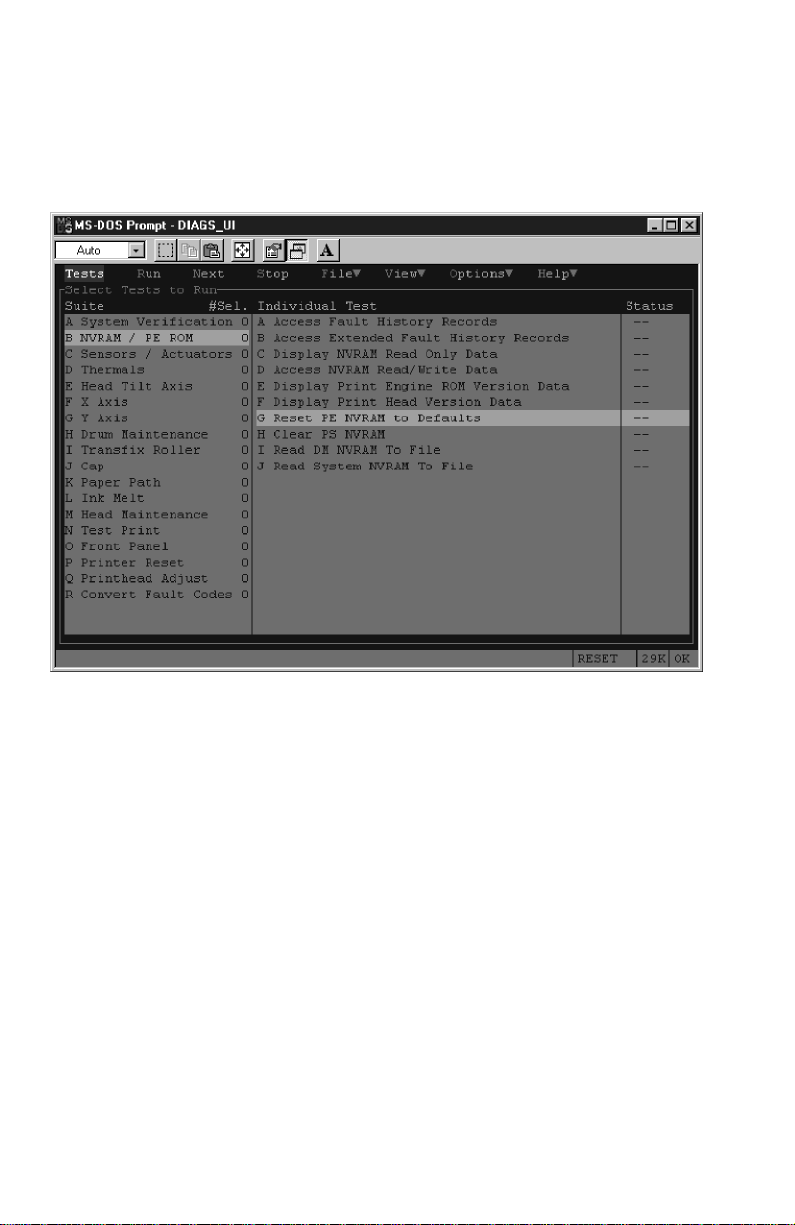
Alternately, you can also use the PC diagnostics to selectively return either the
print engine NVRAM contents or the PostScript NVRAM contents to their factory
default values as shown in the following illustrations.
Running
the printer that performs the indicated reset function; there is no confirmation or
cancel function.
Reset PE NVRAM to Default
or
Clear PS NVRAM
downloads a file to
Resetting print engine NVRAM menu item
84
Phaser 840 Color Printer
Page 95

Clearing PostScript NVRAM menu item
Service Guide
85
Page 96

86
Phaser 840 Color Printer
Page 97

Key FRU Removal and
Replacement
This topic illustrates how to remove and replace key printer Field Replaceable
Units (FRUs). For more detailed removal/replacement procedures, refer to the
Color Printer Service & Support Resources CD-ROM
Main board
■
Power control board
■
Power supply
■
Upper feed roller assembly
■
Preheat/drum heater assembly.
■
Drum/transfix assembly.
■
Drum position sensor assembly
■
Printhead
■
X-axis motor and drive assembly
■
Y-axis belt drive assembly
■
Cap/wipe/purge assembly
■
. Procedures included here are:
This topic concludes with a discussion about printhead locking.
Service Guide
87
Page 98

Main board
1.
Power down the printer. Leave the power cord plugged in to provide a
ground path for static discharges. Remove the interface cables.
2.
Loosen the two rear panel securing screws.
3.
Slide out the main board.
If you are replacing the main board, transfer the socketed realtime clock/
NVRAM chip and the printer ID chip to the new board so the printer’s settings
and Ethernet address are retained. Also swap the SCSI riser board, code ROM
DIMM and the SDRAM DIMMs.
RAM
DIMMS
SCSI
riser
board
Printer
ID
Main
board
Real time
clock/NVRAM
Code ROM
DIMM
Removing the main board
88
Phaser 840 Color Printer
840-4-36
Page 99

Power supply
Warning
1.
Turn off the printer and remove the power cord.
2.
Remove the right cover. Remove the left cover.
3.
Remove the rear cover.
4.
Remove the top cover.
5.
At the right side of the printer, disconnect the two wiring harnesses
leading to the power supply.
6.
Remove the four screws securing the power supply in place. Remove
the power supply.
Even when the printer is off, AC line voltages may be present at
the printer heaters while the printer is plugged into AC power.
Wiring
harnesses
Power supply
Removing the power supply
Service Guide
840-4-32
89
Page 100

Power control board
1.
Turn off the printer and remove the power cord.
2.
Remove the right cover. Remove the left cover.
3.
Remove the top cover.
4.
Remove the ink loader.
5.
Remove the main board.
6.
Remove the power supply.
7.
Remove the network card or its cover plate, whichever is in place.
8.
Remove the internal hard drive or cover plate which ever is in place.
9.
Disconnect the wiring harnesses leading to the power control board.
10.
Remove the four screws securing the power control board cover plate.
Remove the plate.
11.
Remove the four screws securing the power control board in place. Lift
and remove the board.
Cover
plate
Removing the power control board
90
Phaser 840 Color Printer
Power
control
board
 Loading...