

Page 1

PHASER® 780
COLOR LASER PRINTER
Service Quick Reference Guide
Warning
The following servicing instructions are for
use by qualified service personnel only. To
avoid personal injury, do not perform any
servicing other than that contained in
operating instructions unless you are qualified
to do so.
This printing: September 1999
063-3041-01
Page 2

Copyright © 1998 by Tektronix, Inc., Wilsonville, Oregon. Printed in the United
States of America. All rights reserved. Contents of this publication may not be
reproduced in any form without permission of Tektronix, Inc.
®
Tektronix
, Phaser®, and Made for Each Other® are registered trademarks of
Tektronix, Inc. TekColor™, PhaserShare™, PhaserMatch™, PhaserLink™,
Finepoint™ and PhaserPrint™ are trademarks of Tektronix, Inc.
RealSUPPORT
SM
and TekColor CareSM are service marks of Tektronix, Inc.
Other marks are trademarks or registered trademarks of the companies with
which they are associated.
October 1998: First Printing
December 1998: Changed pages; 2, 3, 15, 72, 78, 92, 93, 105, 108, 109, 111, 113, 114,
115, 117, 121, 124, 127, 129, 134, 137, 138, 139, 140, 141, 144, 145
TE/mq/mm
Page 3

Users safety summary
Terms in
manual:
Power source:
between the supply conductors or between either supply conductor and ground.
Use only the specified power cord and connector. For 220 VAC printers, Do not
apply more than 250 volts RMS between the supply conductors or between either
supply conductor and ground. Use only the specified power cord and
connector.Refer to a qualified service technician for changes to the cord or
connector.
Operation of product:
technician to replace fuses inside the product. Do not operate without the covers
and panels properly installed. Do not operate in an atmosphere of explosive
gases.
Safety instructions:
product into a power source.
Terms on
product:
CAUTION Conditions that can result in damage to the product.
WARNING Conditions that can result in personal injury
or loss of life.
For 110 VAC printers, Do not apply more than 130 volts RMS
Avoid electric shock by contacting a qualified service
WARNING Turning the power off using the On/Off switch does
not de-energize the printer. You must remove the power cord to
disconnect the printer from the mains. Keep the power cord
accessible for removal in case of an emergency.
Read all installation instructions carefully before you plug the
CAUTION A personal injury hazard exists that may not be
apparent. For example, a panel may cover the hazardous area.
Also applies to a hazard to property including the product itself.
DANGER A personal injury hazard exists in the area where
you see the sign.
Care of product:
Disconnect the power plug if the power cord or plug is frayed or otherwise
damaged, if you spill anything into the case, if product is exposed to any excess
moisture, if product is dropped or damaged, if you suspect that the pr oduct needs
servicing or repair, and whenever you clean the product.
Ground the product:
grounded AC outlets only. If necessary, contact a licensed electrician to install a
properly grounded outlet.
Disconnect the power plug by pulling the plug, not the cord.
Plug the three-wire power cord (with grounding prong) into
Page 4
Symbols as marked on product:
DANGER high voltage:
Protective ground (earth) terminal:
Use caution. Refer to the manual(s) for information:
!
Laser use caution. Refer to the manual(s) for information:
WARNING:
controls (and other conductive parts) can cause an electrical shock. Electrical
product may be hazardous if misused.
If the product loses the ground connection, usage of knobs and
Page 5
Service safety summary
For qualified service personnel only:
Refer also to the preceding Users Safety
Summary.
Do not service alone:
Do not perform internal service or adjustment of this product
unless another person capable of rendering first aid or resuscitation is present.
Use care when servicing with power on:
Dangerous voltages may exist at several
points in this product. To avoid personal injury, do not touch exposed
connections and components while power is on.
Disconnect power before removing the power supply shield, soldering, or
replacing components.
Do not wear jewelry:
Remove jewelry prior to servicing. Rings, necklaces, and
other metallic objects could come into contact with dangerous voltages and
currents.
Power source:
This product is intended to operate from a power source that will
not apply more than 250 volts rms between the supply conductors or between
either supply conductor and ground. A protective ground connection by way of
the grounding conductor in the power cord is essential for safe operation.
This product is certified under IEC 825 as a Class 1 Laser Product.
DANGER:
Invisible laser radiation
when open and interlock
defeated.
AVOID DIRECT
EXPOSURE TO BEAM.
PELIGRO:
Cuando se abre y se
invalida el bloqueo, se
producen radiaciones
invisibles de láser.
EVITESE LA
´
EXPOSICION
DIRECTA A TALES
RAYOS.
CAUTION:
Invisible laser radiation
when open and
interlocks defeated.
AVOID DIRECT
EXPOSURE TO BEAM.
VARNING:
Osynlig laserstrálning när denna
del är öppnad och
spärrar är
urkopplade.
STRÅLEN
ÄR FARLIG.
VORSICHT:
Unsichtbare Laserstrahlung,
wenn Abdeckung geöffnet
und Sicherheitsverriegelung
überbrückt.
NICH DEM STRAHL
AUSSETZEN.
VAROI:
Näkymätön
avattaessa ja
suojalukitus
ohitettaessa olet
alttiina lasersäteilylle.
ÄLÄ KATSO
SÄTEESEN.
ATTENTION:
Rayonnement laser invisible
dangereux en cas
d'ouverture et lorsque
la sécurité est neutralisée.
EXPOSITION DANGEREUSE
AU FAISCEAU.
VARNING:
Osynlig laserstrálning
när denna del är
öppnad och spärrar är
urkopplade.
BETRAKTA EJ
STRÅLEN.
ADVARSEL:
Usynlig laserstràling
ved abning når
sikkerhedsafbrydere
er ude af funktion.
UNDGÅ UD
ÆTTELSE FOR
STRÅLING.
Class 3B
ADVARSEL:
Usynlig laserstraling
nar deksel åpnes og
sikkerhedslas brytes.
UNNGÅ
EKSPONERING
FOR STRÅLEN.
PJQT4521ZA
9008-78
Page 6

Page 7

Contents
General Information 1
Phaser 780 overview 2
Memory considerations 3
Print engine assemblies 5
The image processor 10
Front panel 11
Rear panel 12
Network card LEDs 12
Specifications 14
Regulatory specifications 17
Safety 17
EMC 17
Energy Star certification 17
Error Codes and Messages 19
Troubleshooting 39
System power-up sequence 39
Print engine troubleshooting 40
Printer will not power up 40
Erratic printer operation 41
Making a print engine only test print 42
Printing and print quality problems 43
Initial checks and actions 43
Light (undertone) prints 44
Blank prints 45
Monochrome prints 46
Black prints 47
One color is faded 47
Missing band in direction of paper travel 48
Missing bands in parallel to the leading edge 49
Streaks in direction of paper travel 51
Streaks parallel with the leading edge 52
Banding 53
Edge of print is wrinkled with an area of ragged discoloration. 53
Random missing spots 54
Random spotting 55
Repetitive mark appears on each print 56
Residual image or ghosting 56
Background contamination 57
Unfused image or image easily rubs off of page 58
Toner on back of print 58
Service Guide
vii
Page 8

Print is mottled 59
Image mis-registered on paper 60
Color layer not correctly registered 60
Color representation not correct 61
Oil stain or gloss variation on print 61
Random spotting 62
Media jams and the paper path 63
Skewed image 63
Damaged prints 64
Inoperative lower tray feeder 65
Power problems 65
All front panel indicators remain off. The printer does not initialize
upon power-up 65
Front panel indications 66
Media tray indicates missing or empty when it is not 66
Macintosh printing problems 66
Image never prints 66
Image prints in black-and-white 66
Image is rotated 90 degrees 67
Windows printing problems 67
Image never prints 67
Blue color on the screen is printing too purple. 67
Printing from Windows 3.1 produces the message “Problem writing
device LPT1: Cancel or Retry”. 68
Workstation printing problems 68
Image never prints 68
Running built-in diagnostics 69
Adjustments 73
Printing test prints 73
Print service test prints 73
Printing the configuration page 73
Printing the demonstration pages 73
Print engine calibration 74
Adjusting for impulse banding 74
Cleaning and Maintenance 77
Service preventive maintenance procedure 77
Recommended tools 77
Cleaning 78
Resetting NVRAM 79
viii
Phaser 780 Color Printer
Page 9

Key FRU Disassembly 81
Paper feeder 82
Feeder registration chute 83
Feeder registration clutch 84
Registration brake clutch 85
Feeder metal registration roller 86
Feeder rubber registration roller 87
Feeder pre-registration clutch 88
Feeder pre-registration rollers 89
Paper-pick turn roller 91
Paper feed drive gear train 92
Paper-feed motor 93
Multi-purpose tray roller assembly 94
Multi-purpose tray pick rollers 95
Auto-density calibration sensor 97
Developer assembly 99
Developer clutch 101
Developer tie plate 102
Toner/developer dispense motor 104
Carousel assembly 105
Carousel motor 107
Carousel motor board 108
Carousel sensor 109
Laser unit 110
Erase lamp rail assembly 112
Erase lamp 114
Process drive unit 115
Waste auger assembly 117
Accumulator belt assembly 119
Accumulator belt cleaner assembly 121
Second bias transfer roller assembly 122
Second bias transfer roller cam assembly 123
Fuser assembly 125
Fuser drive gear train 126
Lower exit assembly 128
Full stack sensor 130
Low voltage power supply 131
High voltage power supply 132
Image processor 133
Image processor chassis 134
Print engine control board 135
Service Guide
ix
Page 10

FRU List 137
Supplies and accessories 176
Test Prints 179
Wiring Diagrams 185
x
Phaser 780 Color Printer
Page 11

Figures
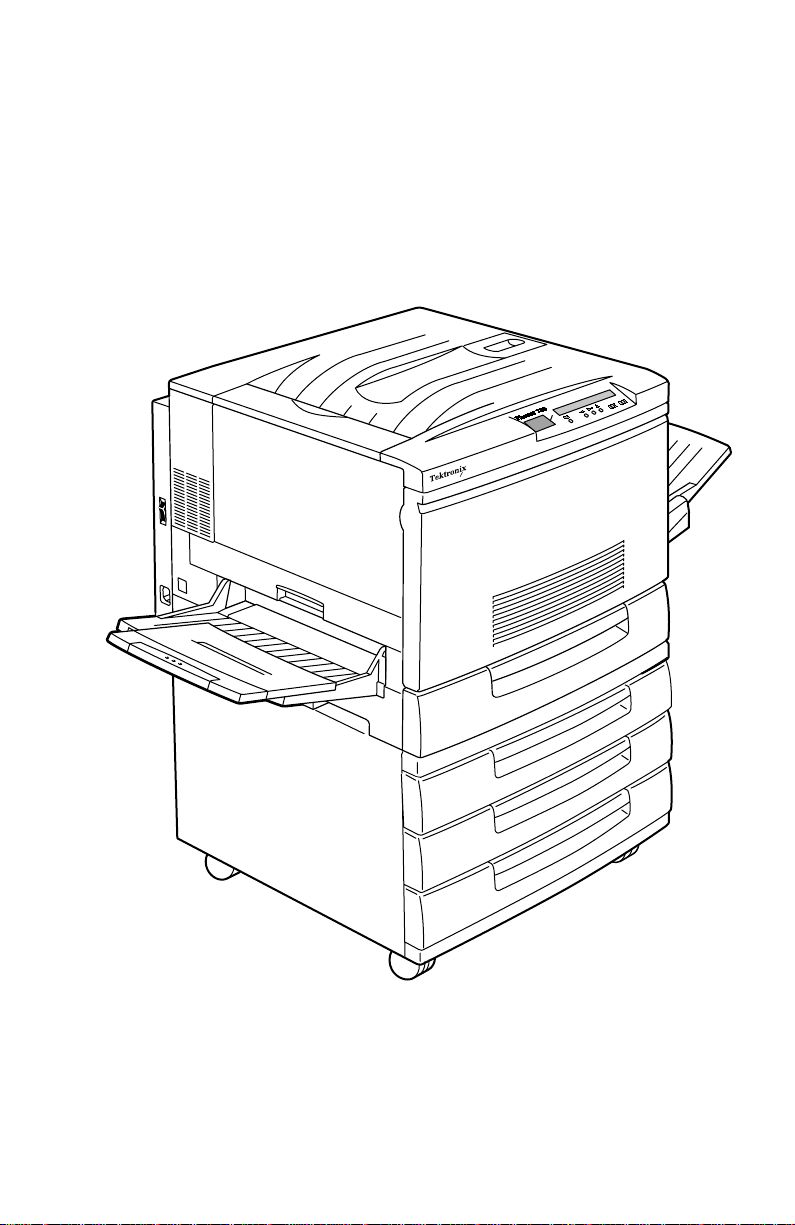
The Phaser 780 printer (shown with optional Lower Tray Assembly) 1
Internal features of the print engine 5
Circuit boards of the print engine 6
Motors of the print engine 7
Sensors and switches on the print engine 8
Solenoids and clutches on the print engine 9
Features of the image processor board 10
Printer front panel 11
Printer rear panel with the optional Ethernet card 13
Adjusting for impulse banding 75
Removing the paper feeder 82
Removing the registration chute 83
Removing the registration clutch 84
Removing the registration brake clutch 85
Removing the metal registration roller 86
Removing the rubber registration roller 87
Removing the feeder pre-registration clutch 88
Removing the feeder pre-registration roller 90
Removing the paper-pick turn roller 91
Removing the paper-feed drive gear train 92
Removing the paper-feed motor 93
Removing the multi-purpose tray roller assembly 94
Removing the multi-purpose tray pick rollers 96
Removing the auto-density calibration sensor 98
Removing a developer assembly 100
Removing the developer clutch 101
Removing the developer tie plate 103
Removing the toner/developer dispense motor 104
Removing the carousel assembly 106
Removing the carousel motor 107
Removing the carousel motor board 108
Removing the carousel sensor 109
Removing the laser unit 111
Removing the erase lamp rail assembly 113
Removing the erase lamp 114
Removing the process drive unit 116
Removing the waste auger assembly 118
Removing the accumulator belt assembly 120
Removing the accumulator belt cleaner assembly 121
Removing the second bias transfer roller assembly 122
Service Guide
xi
Page 12

Removing the second bias transfer roller cam assembly 124
Removing the fuser assembly 125
Removing the fuser-drive gear train 127
Removing the lower exit assembly 129
Removing the stack full sensor 130
Removing the low voltage power supply 131
Removing the high voltage power supply 132
Removing the image processor 133
Removing the image processor chassis 134
Removing the print engine control board 135
Printer cabinet FRUs 138
Paper feeder FRUs 140
Multi-purpose tray cover FRUs 142
Multi-purpose tray FRUs 144
Paper feeder cover FRUs 146
Paper feeder FRUs 148
Imaging FRUs 150
Developer FRUs 152
Carousel FRUs 154
Accumulator belt assembly FRUs 156
Fuser assembly FRUs 158
Paper exit FRUs 160
Paper exit FRUs 162
Drive FRUs 164
Electronic (rear) FRUs 166
Electronics (front) FRUs 168
Image processor FRUs 170
Optional lower feeder cabinet FRUs 172
Optional Feeder FRUs 174
Print engine wiring diagram 185
Map 1 – Wiring routing at the top and front of the printer 193
Map 2 – Wire routing around the engine control board 194
Map 3 – Wiring routing around the image processor board 195
Map 4 – Wiring routing around the paper feeder 196
Map 5 – Wire routing around the laser scanner and high voltage power supply 197
Map 6 – Wire routing at the rear of the printer 198
Map 7 – Wire routing around the power supply 199
Map 8 – Wire routing around the fuser 200
Wiring 1 – Low voltage power supply, laser unit, and interlock switches 201
Wiring 2 – Engine control board, auto-density calibration sensor, erase lamp, waste
toner sensor 202
Wiring 3 – Low voltage power supply, engine control board, high-voltage power
supply and imaging components 203
xii
Phaser 780 Color Printer
Page 13

Wiring 4 – Engine control board, used cartridge sensor, cartridge sensor, carousel
sensor, developer clutch, developer fan, toner dispense motor 204
Wiring 5 – Engine control board, low voltage power supply, carousel motor board,
rotary motor 205
Wiring 6 – Engine control board, low voltage power supply, bias transfer roller cam
solenoid accumulator belt sensor, paper feeder motor, process motor 206
Wiring 7 – Engine control board, low voltage power supply, fuser, oil roll assembly
207
Wiring 8 – Engine control board, fuser assembly, environment sensor 208
Wiring 9 – Engine control board, paper size switch board, feed solenoid, no paper
sensor, low paper sensor 209
Wiring 10 – Engine control board, paper feeder 210
Wiring 11 – Engine control board, paper feeder, multi-purpose tray 211
Wiring 12 – Engine control board, top exit sensor, media exit switch, full stack sensor,
fuser fan 212
Wiring 13 – Engine control board, image processor board, front panel, image processor
fan 213
Wiring 14 – Lower Tray Assembly master wiring diagram 214
Wiring 15 – Engine control board and low voltage power supply to Lower Tray
Assembly feeder board 215
Wiring 16 – Lower Tray Assembly feeder board to feeder chute switch, size switches
and feeder motor 216
Wiring 17 – Lower Tray Assembly feeder board to no paper sensors and low paper
sensors 217
Wiring 18 – Lower Tray Assembly feeder board to feed solenoids and turn chutes 218
Service Guide
xiii
Page 14

Tables
Memory and features sets 3
Physical dimensions of printer 14
Physical dimensions of lower tray feeder 14
Printer clearances 14
Functional specifications 15
Electrical specifications 16
Environmental specifications 16
Diagnostic tests 69
Printer cover FRUs 139
Paper feeder FRUs 141
Multi-purpose tray cover FRUs 143
Multi-purpose tray FRUs 145
Paper feeder cover FRUs 147
Paper feeder FRUs 149
Imaging FRUs 151
Developer FRUs 153
Carousel FRUs 155
Accumulator belt assembly FRUs 157
Fuser assembly FRUs 159
Paper exit FRUs 161
Paper exit FRUs 163
Drive FRUs 165
Electronic (rear) FRUs 167
Electronic (front) FRUs 169
Image processor FRUs 171
Optional lower feeder cabinet FRUs 173
Optional feeder FRUs 175
Supplies and accessories 176
Plug/Jack Locations - 1 186
Plug/Jack Locations - 2 187
Plug/Jack Locations - 3 188
Plug/Jack Locations - 4 189
Plug/Jack Locations - 5 190
Plug/Jack Locations - 6 191
Plug/Jack Locations - 7 192
xiv
Phaser 780 Color Printer
Page 15
General Information
This service guide contains information useful to verify operation, troubleshoot,
repair, adjust, and maintain a Tektronix Phaser® 780 Color Printer.
To ensure complete understanding of the product, we recommend participation
in Phaser 780 service training, if available.
The Phaser 780 printer (shown with optional Lower Tray Assembly)
Service Guide
3041-01
1
Page 16

Phaser 780 overview
The Phaser 780 Color Printer combines a color laser, continuous-tone print engine
with an image processor supporting Adobe’s PostScript 3 page description
language. The image processor features a bi-directional parallel interface and a
10baseT Ethernet port for host communication. Optional network adapter cards
to the image processor allow the printer to communicate on networks using
LocalTalk, Ethernet 100baseT or Token Ring protocols. The Ethernet network
card supports EtherTalk 100baseT, Novell and TCP/IP. With the Token Ring
network card, the printer supports Token Ring protocols. The network cards are
sometimes referred to as “smart cards” because each houses its own processor for
executing specific on-board protocols; only data is transferred from the installed
smart card to the printer’s image processor board. The PCL printer language is
also supported.
The printer is marketed in three versions:
Phaser 780 N
The
printer contains 136 standard, built-in fonts. The standard Phaser 780 prints at a
resolution of 600 x 600 dots-per-inch on A and B-size media. The base printer
does not support grayscale printing.
Phaser 780 GN
The
600 x 1200 dpi. It also contains 136 fonts. The graphics printers supports 16 level
grayscale printing as well as printing oversize-B images.
Phaser 780 P
The
features as the GN printer. In addition, the Plus version Phaser 780 supports
image pipelining for greater throughput, a print collation mode, and a “check
print before proceeding with job” mode. The plus printer also feature a SCSIcompatible interface to connect to an external hard disk drive for additional font
storage. The hard disk drive is also required for print collation of multiple copy
multi-page prints. A scanner can also be connected to the Plus printer’s SCSI port
to give the printer the ability to optically copy color images.
RAM memory in the printers can be supplemented with one or two additional 32, 64-, or 128-Mbyte RAM DIMMs; the maximum usable capacity is 192 Mbytes
Print speeds depend on the chosen resolution and selected media. For r esolutions
of 600 x 600 (standard), in color, the printer prints at 4 A-size pages per minute
(ppm) on paper . Monochrome printing (Fast Monochr ome) is at 16 ppm on paper .
Transparency film printing is always 2 ppm.
The printers support printing on A-, A4-, A5-, B-, B4, B5, SRA3, A3-, 13 x 19 in.
and Legal-sized paper from a 250-sheet tray. An optional three-tray second feeder
(called the Lower Tray Assembly) is available with additional 250-sheet standard
media trays. The printer features a built-in multi-purpose tray from which
specialty media, cardstock and envelopes can be fed. The printer also supports
manual feeding using the multi-purpose tray.
(Standard) comes standard with 64 Mbytes of RAM. The
(Graphics) features 96 Mbytes of RAM and can print at
(Plus) features 192 Mbytes of RAM and supports the same
After being idle for the selected amount of time the printer switches into its
Energy Star mode where it consumes less than 45 watts of power. It “awakens”
upon receiving data at any of its ports.
2
Phaser 780 Color Printer
Page 17

Memory considerations
The base printer features 32 Mbytes of RAM in one connector and features two
additional DIMM connectors which accept 16-, 32-, 64-, or 128 Mbytes RAM
DIMMs. The printer can use any off-the-shelf RAM meeting these specifications:
■
168 pin DIMM
■
Synchronous DRAM
■
3.3 volt
■
9 nsec speed
■
Valid on-board Serial Presence Detect ROM.
Upon power-up, the image processor interrogates the 256 byte Serial Presence
Detect ROM which describes the DIMM in great detail, with details such as data
width, clock delay, number of address columns and row, refresh rate and more. If
the DIMM does not meet the required specifications it will be ignored; no error
message will be reported.
With more memory the printer gains the capabilities of printing at higher
resolutions, printing without having to use image compression (which trades off
less installed RAM for longer image processing time) and dual frame buffers for
printing one image while processing a second image (which gives greater
printing throughput). With additional RAM memory, the printer’s capabilities
increase as detailed in the following table:
Table 1 Memory and features sets
Configuration/ options “Standard”
600 x 600 with full image
area
600 x 1200 with full
image area
Check Print/ PhaserMatch No No Yes
Job Pipelining No No Yes - 2 pages
Parallel port buffer 256 kbytes 256 kbytes 512 kbytes
Print Collation - requires
hard drive option
Fonts available 136 136 136
printer
w/ 64 Mbyte
RAM
Yes Yes Yes
No Yes Yes
No No Yes
“Graphics”
printer
w/ 96 Mbyte
RAM
“Plus” printer
w/ 192 Mbyte
RAM
Service Guide
3
Page 18

Print the Configuration Page and check the item “installed RAM” to see what
type of RAM is installed.
For example:
Installed RAM: 96 Mbytes
Mem slot 1: SDRAM/parity/64 MB/KMM366S824AT
Mem slot 1: empty
This is a list of DRAM SIMMs that are branded for use by Tektronix at the time
this guide was published:
Size
16 Mbyte Samsung KMM366S203BT
32 Mbyte Samsung KMM366S403BT
64 Mbyte Samsung KMM366S824AT
128 Mbyte Samsung KMM366S1623AT
32 Mbyte Smart Module SM564043574N6AA
64 Mbyte Smart Module SM564088574N6AA
32 Mbyte NEC MC-454AD645F-A10B
64 Mbyte NEC MC-454CB645FA-A10B
128 Mbyte NEC MC-4516CD645FZ-A10B
16 Mbyte Micron Tech. MT8LSDT264AG-66CL2
32 Mbyte Micron Tech. MT16LSDT264AG-10BC4
32 Mbyte Micron Tech. MT16LSDT264AG-662C1
64 Mbyte Micron Tech. MT8LSDT864AG-662D3
64 Mbyte Micron Tech. MT8LSDT864AG-10BD2
128 Mbyte Micron Tech. MT16LSDT1664AG-662DT
Maker Part Number
4
Phaser 780 Color Printer
Page 19
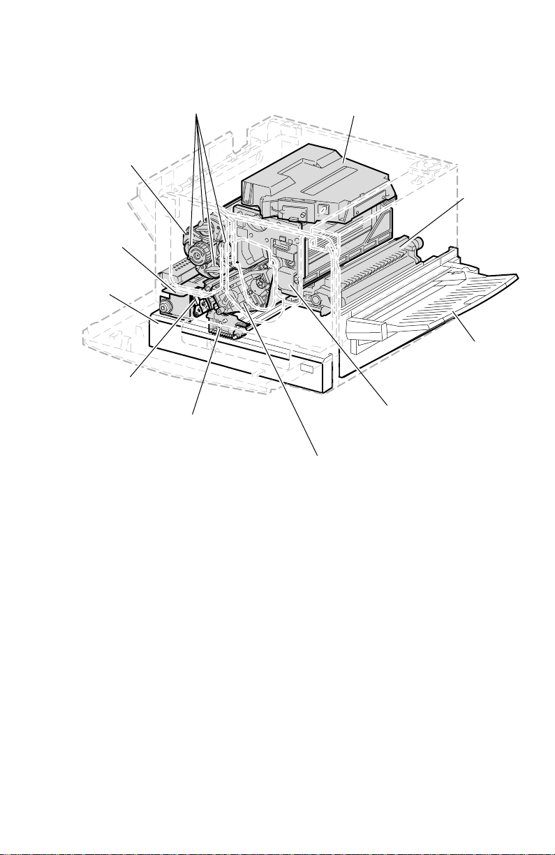
Print engine assemblies
Carousel
assembly
Fuser
Media
tray 1
Accumulator
belt cleaner
Developer
assemblies
Second bias
transfer roller
Laser
unit
Accumulator
belt assembly
Paper
feeder
Multi-purpose
tray
Imaging unit
3041-02
Internal features of the print engine
Service Guide
5
Page 20
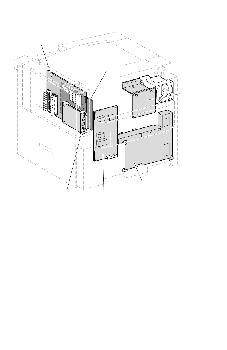
.
Image
processor
board
Engine
control
board
Carousel
motor
board
Network
card
Circuit boards of the print engine
6
Phaser 780 Color Printer
High Voltage
board
Low Voltage
Power Supply (LVPS)
3041-04
Page 21
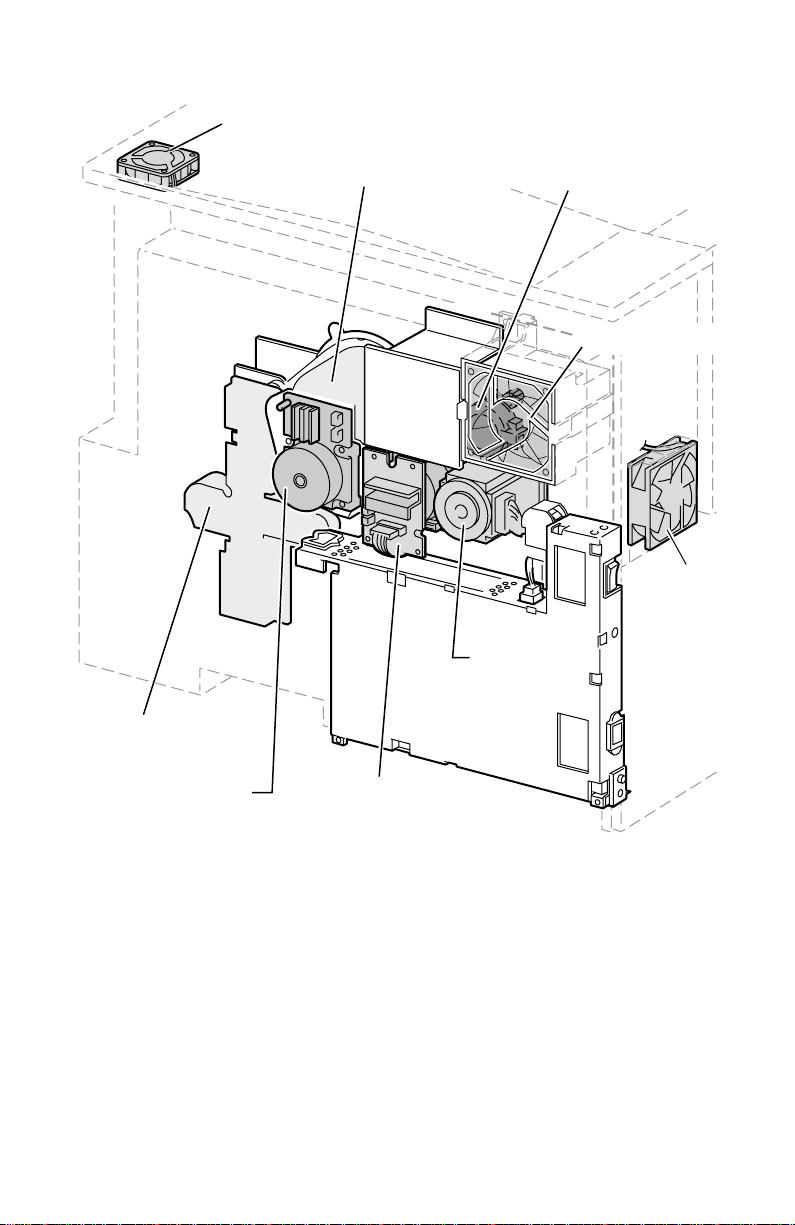
Image processor
fan
Process drive
assembly
Toner
dispense
motor
Developer fan
Fuser fan
Paper
feed drive
gear train
Process
motor
Motors of the print engine
Paper feed
motor
Carousel
motor
Service Guide
3041-03
7
Page 22
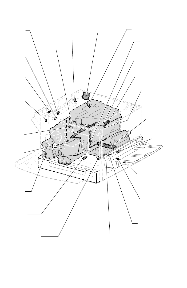
Exit
ensor
Used toner
artridge
ensor
Full
stack
sensor
Left front
cover
switch
Toner
cartridge
presence
sensor
user
emperature
ensor
Auto-density
calibration
sensor
Exit door
sensor
Top cover
switch
Carousel
sensor
Right front
cover switch
Waste cartridge
full sensor
Waste cartridge
sensor
Accumulator
belt home
sensor
Paper size
sensor
Edge
sensor
Fuser exit
ensor
Environment
sensor
Registration
sensor
Sensors and switches on the print engine
8
Phaser 780 Color Printer
Multi-purpose
tray paper
present sensor
Long paper
sensor
Low paper
sensor
Paper empty
sensor
3041-05
Page 23
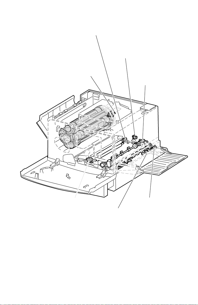
Registration
clutch
Second bias
transfer roller
solenoid
Developer clutch
Registration
brake clutch
Multi-purpose
tray clutch
Pre-Registration
clutch
Multi-purpose
pick-up solenoid
3041-06
Solenoids and clutches on the print engine
Service Guide
9
Page 24
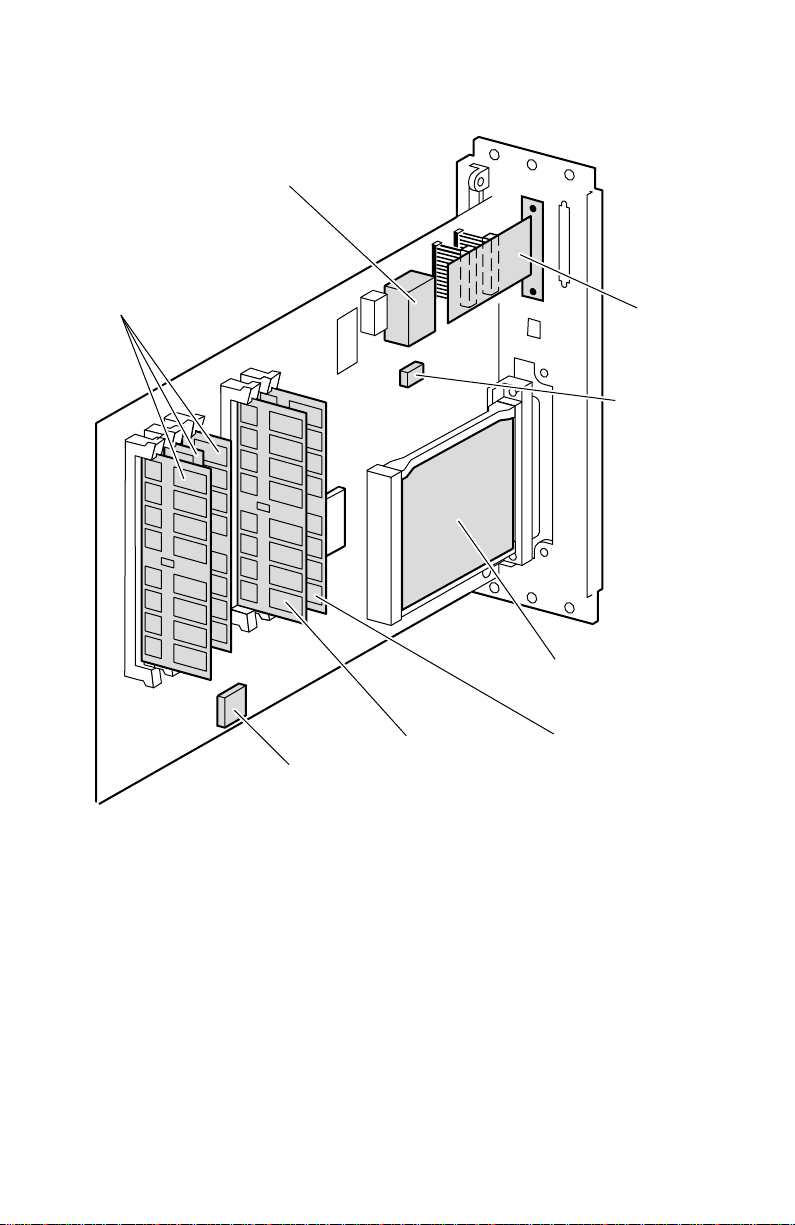
The image processor
Real Time Clock / NVRAM
RAM
DIMMS
Boot
ROM
Features of the image processor board
Font
DIMM
SCSI
riser
card
NVRAM
Network
card
Postscript
code ROM
DIMM
3041-07
10
Phaser 780 Color Printer
Page 25
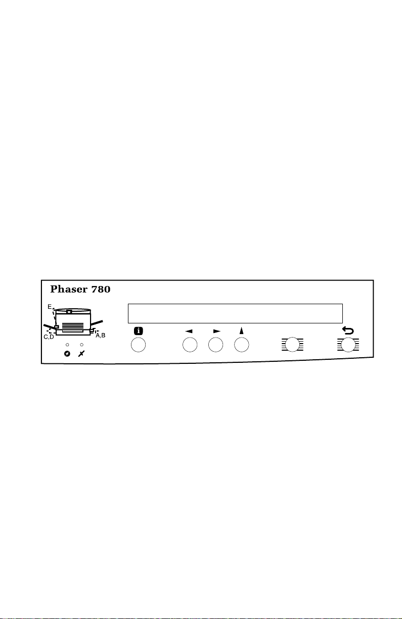
Front panel
These front panel features are found on the printer:
■
A two-line, 40-character LCD
■
Six push buttons
■
Five LEDs
LCD.
The LCD serves two purposes: Displaying current image processor and
print engine status information and displaying an interactive menu. Status
information includes image processor status such as
Printing
Jam
. Print engine status includes messages such as
, and
Toner Low
.
Ready, Processing
Out of paper, Paper
The interactive menu can only be entered while the printer is idle and r eady. The
interactive menu has two modes, review and modify. Customers can review and
modify certain NVRAM, I/O ports and peripheral parameters.
and
Buttons.
Button 6, the left-most button, is an
Exit key used to cancel an operation
while in the interactive menu. The functions of the remainder of the buttons are
defined by the particular menu or function being displayed on the LCD. The
bottom row of the LCD labels the current function of each button.
Ready
Print Menu Select
3041-18
Printer front panel
Service Guide
11
Page 26

Rear panel
Connectors
The rear panel of the printer features the host interface connectors:
■
Bi-directional parallel (high-density connector).
■
Twisted Pair 10baseT Ethernet connector. RX indicator (green);
while the network card is receiving data. The LED is
data is being received. If the LED is
on steady
, then a problem (probably
off steady
hardware) has occurred at the network hub.
■
SCSI high-density connector (external hard disk drive or optical scanner
only).
With the addition of a network card, the printer can feature either of these groups
of connectors:
■
ThinNet (100base2) and Twisted Pair (100baseT) Ethernet connectors.
This is Option P1.
■
LocalTalk connector. This is Option P3.
■
Unshielded Twisted Pair (10baseT) and shielded Twisted Pair (DB-9)
Token Ring connectors. This is Option P4.
Network card LEDs
blinks
while no
The Ethernet network card has four LED indicators:
■
TX indicator (yellow); blinks while data is transmitted to the host. The
LED is off while no data is being sent.
■
Twisted Pair (100baseT) and ThinNet (100base2). RX indicator (green);
blinks
while the network card is receiving data. The LED is
while no data is being received. If the LED is
on steady
off steady
, then a problem
(probably hardware) has occurred at the network hub.
■
TP Link. On steady indicates good circuit to nearest port; off indicates
no circuit.
■
100 MBS. Ethernet speed is 100 MBS when lit.
Note
Do not use both Ethernet connectors at the same time. With a
Ethernet or Token Ring network card installed, the 10baseT port
is disabled.
12
Phaser 780 Color Printer
Page 27
The Token Ring network card has two LED indicators:
■
Connection (yellow);
blinks
Ring,
Ring,
■
Ring Speed (green);
(MBPS),
■
When both LEDs blink, a network card failure has occurred.
while the printer is attempting to insert itself into the Token
on
when the printer is properly inserted in the ring.
on
when the card is set for 16 MBPS.
off
when the printer is not inserted into the Token
off
when the card is set for 4 megabits-per-second
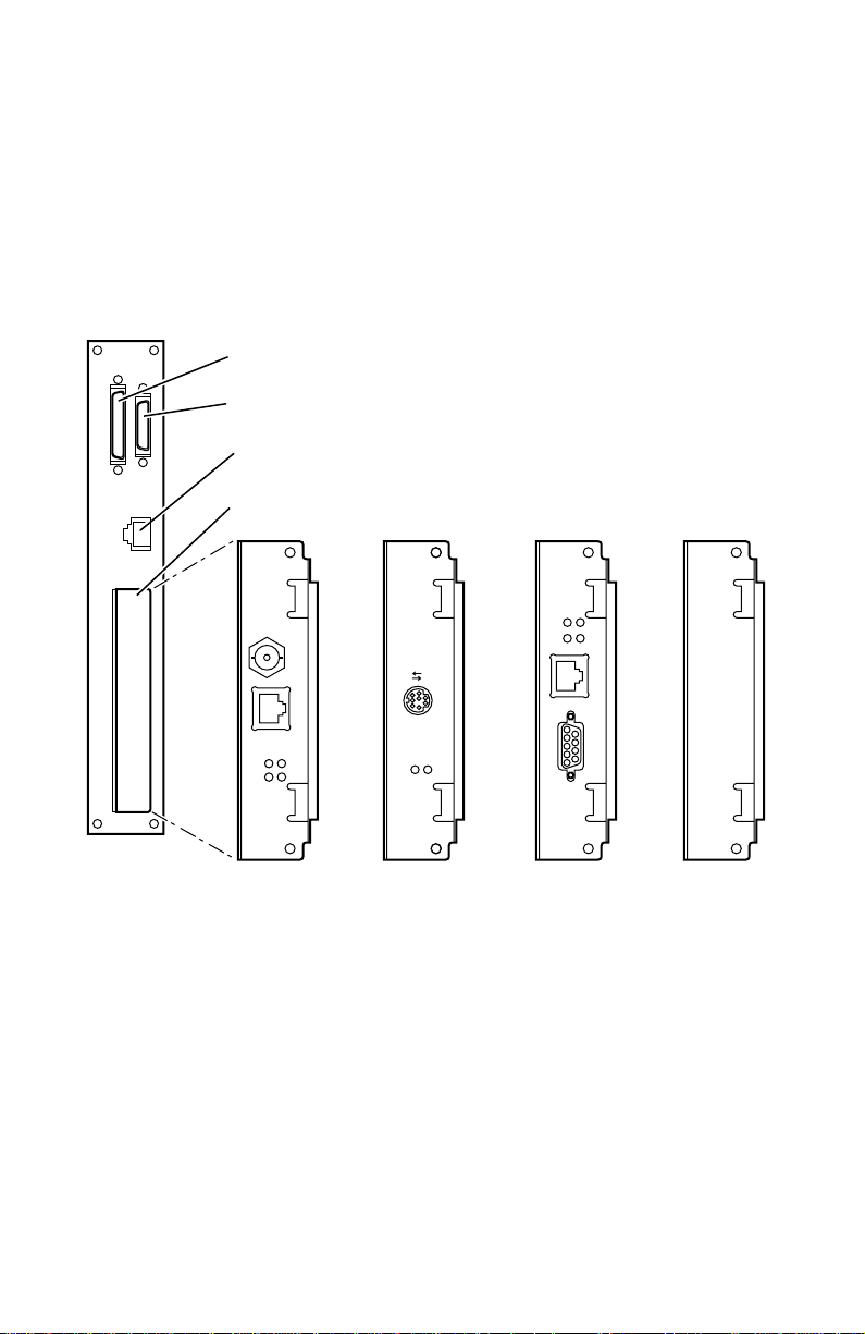
The following figure illustrates the rear panel of the printer.
SCSI port
Parallel port
10 base T ethernet port
Slot for network card & IDE hard drive
TX
RX
16
INS
10Base2
LocalTalk®
Mbs
UTP
10/100Base-TX
100
Mbs
TP
LINK
TX
RX
TM
Series B
Ethernet Card
PhaserShare
Ethernet
card
TX
RX
TM
Series B
PhaserShare
LocalTalk Card
LocalTalk
card
Printer rear panel with the optional Ethernet card
STP
TM
Series B
PhaserShare
Token Ring Card
Token Ring
card
Service Guide
Internal
hard drive
3041-08
13
Page 28

Specifications
Table 1 Physical dimensions of printer
Dimension Value
Height 49.2 cm (19 in) without lower tray feeder
Width 69.1 cm (27.2 in)
Depth 64.1 cm (24.2 in)
Weight 73.6 kg (161 lbs) with consumables installed
90.6 (36 in) with lower tray feeder
97.1 kg (213 lbs) with lower tray feeder and consumables
Table 2 Physical dimensions of lower tray feeder
Dimension Value
Height 41.4 cm (16.3 in)
Width 56 cm (22 in)
Depth 56 cm (22 in)
Weight 23.5 kg (52 lbs)
Table 3 Printer clearances
Dimension Value
Top 40.0 cm (15.7 in)
Left 50.3 cm (20 in)
Right 55.1 cm (21.5 in)
Front 83.5 cm (33 in)
Rear
Bottom No obstructions underneath that could block cooling vents
Mounting surface flatness Front feet less than 5 mm above or below rear feet
Mounting surface dimensions
14
Phaser 780 Color Printer
15.0 cm (6 in)
Left feet less than 10 mm above or below right feet
Level surface with dimensions of at least 79 cm (31 in.) by
152 cm (60 in.).
Page 29

Table 4 Functional specifications
Characteristic Specification
Printing process Electro-photographic, four color (CMYK), two transfer printing using
Color medium Four toner cartridges each containing one of four colors: cyan,
Addressability 600 x 600 dpi and 600 x 1200 dpi
Print speed Time from paper load to paper eject:
Minimum margins
Usable papers sizes
Usable paper weights 75 to 105 g/m
Tray capacities Main tray:
modulated (on/off) laser beam scanning. Imaged is fused to paper
using heat and pressure with silicone oil lubricant.
magenta, yellow or black. The toner is a nonmagnetic, dual
component contact medium.
A-size:
Four color: 4 pages per minute
Monochrome: 16 pages per minute
Transparency: 2 pages per minute
B-size:
Four color: 2 pages per minute
Monochrome: 8 pages per minute
Transparency: 1 page per minute
5 mm(0.2 in.) on all sides, except for Tabloid Plus (13 x 19 in.)
media which has a bottom margin of 25 mm (1 in.)
Paper
:
Envelope
:
3.5x5.5, minimum size US #10
8.5x11, Letter Euro Standard
8.5x14, Legal A4
11x17, Tabloid C4
12x18, Tabloid Extra C5
13x19, Tabloid Plus C6
A3 C65
A4
A5
B4
B5
Avery label: 5164, 5663, 7330, 7348
2
(20 to 24 lb) thru paper tray.
64 to 220 g/m2(80 lb) using the multi-purpose tray
Standard paper: 250 sheets
Transparency: 100 sheets
Lower feeder trays:
Standard paper: 250 sheets
Multi-purpose tray:
Standard paper/Letterhead: 150 sheets
Transparency: 50 sheets
Label: 50 sheets
Postcard: 75
Envelope: 30
Glossy/Coated: 75
Index: 30
Fabric Transfer: one at a time
Service Guide
15
Page 30

Table 5 Electrical specifications
Characteristic Specification
Primary line voltage 100/120 VAC (+/- 10%)
Primary voltage frequency
range
Power consumption EnergyStar: 20 watts
220/240 VAC (+/- 10%)
47 to 63 Hz
Standby: 100 watts
1000 watts with fuser on
Ready: 100 watts
1000 watts with fuser on
Printing: 1100 watts
Table 6 Environmental specifications
Characteristic Specification
Temperature:
Operating
Non-operating
Storage
Humidly:
Operating
Non-operating
Storage
0 to 32oC (41 to 90oF)
-20 to40oC (-4 to 104oF)
-20 to40oC (-4 to 104oF)
15 to 85% relative humidity
5 to 85% relative humidity
5 to 85% relative humidity
Altitude
Operating:
Non-operating
Vibration
Operating:
Non-operating
Shock-non-operating
Acoustic Noise
Idle:
Printing:
16
Phaser 780 Color Printer
0 to 3000 m (9900 ft.) at 25
0 to 15000 m (50,000 ft.)
Will withstand 0.5G excitation, 5 to 100 Hz, 3 axes for up to 50 minutes
with no impairment or subsequent damage.
0.5 g, 25 minute sweep, 5-100 Hz, 100-200 sec/sweep cycles
The printer may have any corner raised and dropped 5 cm (2 in.)
without impairment of operation.
38.3 db
54.8 db with impulse noise of 63.3 db
o
C
Page 31

Regulatory specifications
Safety
■ EN60950 CB Report by Third Party GOST and TUV certification
■ UL1950 Nationally Recognized Test Lab (NRTL) certified
■ CSA 950 SCC recognized test lab certified
EMC
■ EN55022 (CISPR 22) Class B
■ EN50082-1:1994 Susceptibility
■ EN61000-3-2 AC Mains Harmonic Distortion
■ EN61000-3-3 AC Mains Voltage Flicker
■ EN61000-4-2:1993 ESD
■ EN61000-4-4:1993 Fast Burst Transients
■ EN61000-4-5:1993 Line Surge
■ EN61000-4-11;1993 Voltage Dips and Interruptions
■ ENV50140:1993 Radiated RF Immunity
Energy Star certification
After 1-hour period of inactivity, the printer enters an standby mode, as required
by Energy Star . The wait time is a user -definable parameter (via the fr ont panel or
by using PhaserLink). Energy Star default is “ON” and the time-out default is
one hour. The printer enters a READY condition within 5 minutes after poweron.
.
Service Guide 17
Page 32

18 Phaser 780 Color Printer
Page 33

Error Codes and
Messages
The following table list error codes and messages reported by the print
engine control board.
Error code
and
message
Laser Unit
Error
(Error 10)
Image
Density Error
(Error 11)
Description Corrective action
There is a problem with the laser unit.
The engine control board did not receive
a signal from the laser start-of-scan
sensor within the specified time
The image density readings indicate a
problem. The engine control board
detected that the printer image density
was unusually low and attempts to raise
the density have failed.
Note
If the top cover is removed,
light can leak into the printer
and cause a auto-density
calibration sensor error.
Test the top cover and right
1.
front cover switches for
proper operation. Power for
the laser unit is routed
through both switches
Replace the laser unit.
2.
Replace the engine control
3.
board
1.
Power cycle the printer
Inspect the toner cartridges.
2.
Inspect the four developer
3.
housings. Each magnetic
roller should be evenly
coated with toner. Replace a
suspect developer assembly.
Test the toner/developer
4.
dispense motor. Replace it if
it does not run
Inspect and reseat the
5.
auto-density calibration
sensor. Ensure the senor’s
solenoid-activated cleaning
blade is in place and moves
freely.
Test the auto-density
6.
calibration sensor. If bad,
replace the auto-density
calibration sensor
Replace the imaging unit
7.
8.
Replace the engine control
board
9.
Replace the high voltage
board
Service Guide
19
Page 34

20
Error code
and
message
Image
Density Error
(Error 12)
Description Corrective action
The image density readings indicate a
problem. The engine control board
detected that the printer image density
was unusually high and attempts to
lower the density have failed.
Power cycle the printer
1.
2.
Ensure the toner cartridges
are fully functional and
relatively full of toner.
Test the toner dispense
3.
motor.
4.
Check the auto-density
calibration sensor for
contamination from toner.
Replace the sensor, if
necessary.
5.
Inspect and reseat the
auto-density calibration
sensor. Ensure the senor’s
solenoid-activated cleaning
blade is in place and moves
freely.
Test the auto-density
6.
calibration sensor. If bad,
replace the auto-density
calibration sensor
7.
Replace the engine control
board
Inspect the four developer
8.
housings. Each magnet
roller should be evenly
coated with toner. Replace a
suspect developer assembly.
9.
Replace the imaging unit
10.
Replace the high voltage
board
Phaser 780 Color Printer
Page 35

21
Error code
and
message
Autodensity
Calibration
Error
(Error 13)
Toner
Carousel
Error
(Error 21)
Description Corrective action
There is problem with the auto-density
calibration. The engine control board
detected that the auto-density
calibration sensor LED output signal is
below specified range.
1.
Power cycle the printer
Check the auto-density
2.
calibration sensor for
contamination from toner.
Replace the sensor, if
necessary.
Inspect and reseat the
3.
auto-density calibration
sensor. Ensure the senor’s
solenoid-activated cleaning
blade is in place and moves
freely.
4.
Test the auto-density
calibration sensor. If bad,
replace the auto-density
calibration sensor
Replace the engine control
5.
board
6.
Replace the low voltage
power supply
There is a problem with the carousel
home sensor. The engine control board
detected that the carousel home sensor
did not actuate within six seconds after
the start of the carousel motor.
Power cycle the printer
1.
2.
Manually rotate the carousel
assembly several revolutions
3.
Check for contamination that
may cause binding.
Test the carousel home
4.
sensor. Replace if needed
5.
Replace the carousel motor
6.
Replace the engine control
board
PCDC Error
(Error 22)
Environment
Sensor Error
(Error 23)
There is a problem with PCDC
calibration. The engine control board
detected that PCDC calibration value is
much lower than set specifications.
There is a problem with the environment
sensor circuit. The engine control board
detected an open environment sensor
circuit
Power cycle the printer
1.
2.
Inspect the process drive.
Ensure the drum rotates
Replace the engine control
3.
board
4.
Replace the image processor
board
1.
Power cycle the printer
Replace the environment
2.
sensor
3.
Replace the engine control
board
Service Guide
Page 36

22
Error code
and
message
Second Bias
Transfer
Roller Error
(Error 24)
Fuser
Temperature
Error
(Error 40)
Description Corrective action
The engine control board detected that
the measured current value thru the
second bias transfer roller was not within
specification.
Check the wiring from the
1.
high voltage power supply to
the second bias transfer roller
Replace the second
2.
bias transfer roller
3.
Replace the high
voltage power supply
4.
Replace the
accumulator belt
assembly
5.
Replace the engine
control board
There is a problem with the temperature
of the fuser. The engine control board
detected that the fuser temperature did
not reach 110˚C within six minutes after
the printer was turned on.
Open the fuser door and
1.
ensure the fuser connectors
are properly seated.
2.
Close the fuser and power
cycle the printer. Check that
the fuser heats up
Check for line voltage at P/J
3.
71 pins 1 and 2. If no v oltage
is present replace the power
supply
Replace the fuser
4.
Replace the engine control
5.
board
Fuser
Temperature
Error
(Error 41)
There is a problem with the fuser heat
rod control. The engine control board
detected that the fuser heat rods
remained on longer than the specified
time.
Phaser 780 Color Printer
1.
Open the fuser door and
ensure the fuser connectors
are properly seated.
2.
Close the fuser and power
cycle the printer. Check that
the fuser heats up
Check for line voltage at P/J
3.
71 pins 1 and 2. If no v oltage
is present replace the power
supply
Replace the fuser
4.
Replace the engine control
5.
board
Page 37

23
Error code
and
message
Fuser
Temperature
Error
(Error 42)
Fuser
Temperature
Error
(Error 43)
Description Corrective action
There is a problem with the fuser. The
engine control board senses an open
temperature sensor circuit.
1.
Open the fuser door and
ensure the fuser connectors
are properly seated.
2.
Close the fuser and power
cycle the printer. Check that
the fuser heats up
Check for line voltage at P/J
3.
71 pins 1 and 2. If no v oltage
is present replace the power
supply
Replace the fuser
4.
Replace the engine control
5.
board
There is problem with the fuser. The
engine control board detected that the
fuser did not reach ready temperature
during the specified time.
1.
Open the fuser door and
ensure the fuser connectors
are properly seated.
Close the fuser and power
2.
cycle the printer. Check that
the fuser heats up
Check for line voltage at P/J
3.
71 pins 1 and 2. If no v oltage
is present replace the power
supply
4.
Replace the fuser
Replace the engine control
5.
board
Fuser
Temperature
(Error 44)
The thermistor sensor indicates that the
fuser had reached the set overheat
temperature, The engine control board
has shutdown fuser temperature
operation.
1.
Allow the fuser to cool for 30
minutes
2.
Ensure the fuser wiring
harnesses are plugged in.
Check the fuser fan
3.
4.
Replace the fuser
5.
Replace the engine control
board
Replace the low voltage
6.
power supply
Service Guide
Page 38

24
Error code
and
message
Process
Motor Error
(Error 61)
Paper
Handling
Motor Error
(Error 62)
Imaging Unit
ID Error
(Error 69)
Description Corrective action
There is a problem with the process
motor. the engine control board did not
receive a signal from the accumulator
belt home sensor signal in the specified
time.
Test the process drive
1.
assembly
2.
Test the +24 VDC at P/J
32-11 and frame ground.
Test the accumulator belt
3.
home sensor
4.
Replace the process motor.
5.
Replace the accumulator belt
assembly
Replace the engine control
6.
board
7.
Replace the imaging unit
There is a problem with the paper feed
motor. The engine control board
received a failed signal from the paper
feed motor circuitry.
Power cycle the printer
1.
Replace the paper feed
2.
motor
3.
Replace the engine control
board
Check for mechanical binding
4.
in the paper feed drive gear
train
The engine control board detected a
used CRUM
1.
Reseat the imaging unit
2.
Power cycle the printer
Replace the imaging unit
3.
Replace the engine control
4.
board
Imaging Unit
ID Error
(Error 70)
Imaging Unit
ID Error
(Error 71)
Imaging Unit
Count Error
(Error 72)
There is a CRU Memory problem. The
engine control board detected that the
memory initial value of the installed
imaging unit is wrong.
An incompatible imaging unit is installed
in the printer. The engine control board
detected that the memory device in the
installed imaging unit is incompatible
with the printer.
There is a CRU memory problem. The
engine control board could not read the
CRUM counter value.
Phaser 780 Color Printer
1.
Reseat the imaging unit
Power cycle the printer
2.
Replace the imaging unit
3.
4.
Replace the engine control
board
1.
Power cycle the printer
Reseat the imaging uni
2.
Switch the printer power off,
3.
then on
4.
Replace the engine control
board
Power cycle the printer
1.
2.
Replace the imaging unit with
a new cartridge
3.
Replace the engine control
board
Page 39

25
Error code
and
message
Imaging Unit
ID Error
(Error 73)
Imaging Unit
Comm Error
(Error 74)
Imaging Unit
Comm Error
(Error 75)
Engine
Board Error
(Error 76)
Description Corrective action
The wrong imaging unit is installed in
the printer. The engine control board
detected that the installed imaging unit
is incompatible with the printer.
1.
Power cycle the printer
Replace the imaging unit with
2.
a new cartridge
3.
Replace the engine control
board
There is a CRU memory problem. The
engine control board could not write to
the CRUM.
1.
Power cycle the printer
Reseat the imaging unit in the
2.
printer
3.
Replace the imaging unit with
a new cartridge
Replace the engine control
4.
board
There is a CRU Memory problem. The
engine control board could not
communicate with the CRUM.
1. Power cycle the printer
2. Replace the imaging unit with
a new cartridge
3. Replace the engine control
board
The engine control board detected a
corrupted NVRAM during power-on self
test
1. Power cycle the printer
2. Replace the NVRAM
chip
3. Replace the engine control
board
ROM/
RAM Error
(Error 77)
There is a problem in reading
information from ROM or RAM on the
engine control board. The engine control
board could not read information on the
ROM or RAM.
1. Power cycle the printer
2. Check if +5 VDC is supplied
at P/J33-3 and frame ground.
If not, replace the low voltage
power supply
3. Replace the engine control
board
Service Guide
Page 40

Error code
and
message
Description Corrective action
Image
Contains T oo
Much
Coverage
Replace
Fuser Roll
Cartridge
Waste
Cartridge
Full
Image density exceeded design
specifications.
The engine control board detected that
the first 70mm of the lead edge of the
four color image about to be printed
exceeds the design specification for total
image density . The specification is 280%
or less image density. For example, a
density setting of 100% for each of the
four colors creates a layered four color
image with a combined density of 400%.
The fuser oil roll has reached end of life.
The engine control board detected that
the fuser oil roll has processed the
equivalent of 20,000 sheets of paper
since it was installed.
The waste cartridge is full. The engine
control board detected that the waste
cartridge sensor was on for 1250 print
cycles.
1. Power cycle the printer
2. Print a less complex, color
image to determine if it is
overly dense.
3. Replace the engine control
board
1. Replace the fuser roll
cartridge
2. Power cycle the printer
3. Ensure the fuser connectors
are properly seated
4. Test the fuser using internal
diagnostics
5. Replace the engine control
board
1. Replace the waste cartridge
2. Test the waste cartridge full
sensor using internal
diagnostics
3. Inspect the electrical
contacts and wiring Replace
the waste cartridge full
sensor
4. Replace the engine control
board
Replace
Black Toner
Cartridge
Black image density is too low. The
engine control board detected that the
auto-density calibration sensor reads
the black patch density as being below
specification and that the reading is
either slow to raise or does not raise
after the printer attempts to increase
density.
26 Phaser 780 Color Printer
1. Replace the black toner
cartridge
2. Test the toner/developer
dispense motor
3. Test the auto-density
calibration sensor
4. Replace the engine control
board
Page 41

Error code
and
message
Description Corrective action
Replace
Cyan Toner
Cartridge
Replace
Magenta
Toner
Cartridge
Replace
Yellow Toner
Cartridge
Cyan image density is too low. The
engine control board detected that the
auto-density calibration sensor reads
the cyan patch density as being below
specification and that the reading is
either slow to raise or does not raise
after the printer attempts to increase
density.
Magenta image density is too low. The
engine control board detected that the
auto-density calibration sensor reads
the magenta patch density as being
below specification and that the reading
is either slow to raise or does not raise
after the printer attempts to increase
density.
Yellow image density is too low. The
engine control board detected that the
auto-density calibration sensor reads
the yellow patch density as being below
specification and that the reading is
either slow to raise or does not raise
after the printer attempts to increase
density.
1. Replace the cyan toner
cartridge
2. Test the toner/developer
dispense motor
3. Test the auto-density
calibration sensor
4. Replace the engine control
board
1. Replace the magenta toner
cartridge
2. Test the toner/developer
dispense motor
3. Test the e auto-density
calibration sensor
4. Replace the engine control
board
1. Replace the yellow toner
cartridge
2. Test the toner/developer
dispense motor
3. Test the auto-density
calibration sensor
4. Replace the engine control
board
Replace
Imaging Unit
Fuser Roll
Cartridge
Low
The imaging unit has reached end of life.
The engine control board detected that
the installed imaging unit has reached
end of life.
The fuser oil roll is nearing end of life.
The engine control board detected that
the fuser oil roll is nearing the 20,000
mark.
1. Replace the imaging unit
2. Switch the printer power off,
then on
3. Inspect the CRUM for
damage or contamination.
clean or replace if necessary.
4. Replace the engine control
board
1. Replace the fuser oil roll
2. Replace the engine control
board
Service Guide 27
Page 42

Error code
and
message
Description Corrective action
Waste
Cartridge
Almost Full
Black Toner
Low
Cyan Toner
Low
Magenta
Toner Low
The waste toner box is almost full. The
engine control board detected that the
waste toner box is almost full and will
soon need to be replaced.
The black toner cartridge is low on toner.
The engine control board switched on
the dispense motor for more than 980
seconds in order to raise the image
density to normal.
The cyan toner cartridge is low on toner.
The engine control board switched on
the Dispense Motor for more than 800
seconds in order to raise the image
density to normal.
The magenta toner cartridge is low on
toner. The engine control board switched
on the Dispense Motor for more than
800 seconds in order to raise the image
density to normal.
1. Replace the waste toner box
2. Replace the engine control
board
1. Replace the black toner
cartridge
2. Test the dispense motor
3. Test the auto-density
calibration. Replace it, if
necessary.
4. Replace the engine control
board
1. Replace the cyan toner
cartridge
2. Test the dispense motor
3. Test the auto-density
calibration. Replace it, if
necessary.
4. Replace the engine control
board
1. Replace the magenta toner
cartridge
2. Test the dispense motor
3. Test the auto-density
calibration. Replace it, if
necessary.
4. Replace the engine control
board
Yellow Toner
Low
The yellow toner cartridge is low on
toner. the engine control board switched
on the Dispense Motor for more than
1150 seconds in order to raise the
image density to normal.
28 Phaser 780 Color Printer
1. Replace the yellow toner
cartridge
2. Test the dispense motor
3. Test the auto-density
calibration. Replace it, if
necessary.
4. Replace the engine control
board
Page 43

Error code
and
message
Description Corrective action
Media Low in
Tray 4
Media Low in
Tray 3
Media Low in
Tray 2
Media Low in
Tray 1
The engine control board detected that
the tray 4 low paper sensor is actuated.
The engine control board detected that
the tray 3 low paper sensor is actuated.
The engine control board detected that
the tray 2 low paper sensor is actuated.
The engine control board detected that
the Tray 1 Low Paper Sensor is
actuated.
1. Add paper to tray 4
2. Check for a damaged or
missing sensor actuator.
3. Replace the tray 4 low sensor
4. Replace the engine control
board
1. Add paper to tray 3
2. Check for a damaged or
missing sensor actuator.
3. Replace the tray 3 low sensor
4. Replace the engine control
board
1. Add paper to tray 2
2. Check for a damaged or
missing sensor actuator.
3. Replace the tray 2 low sensor
4. Replace the engine control
board
1. Add paper to tray 1
2. Check for a damaged or
missing sensor actuator.
3. Replace the tray 1 low sensor
4. Replace the engine control
board
Load Media
in Multipurpose T ray
Load Media
in T ra y 4
The multi-purpose tray is out of paper.
The engine control board detected that
the long multi-purpose tray paper sensor
is not actuated.
Tray 4 is out of paper.
The engine control board detected that
the paper empty sensor in tray 4 is
actuated.
1. Load paper into the
multi-purpose tray
2. Test the multi-purpose tray
paper sensors
3. Replace the engine control
board
1. Load paper into Tray 4
2. Test the paper empty sensor
3. Replace the lower feeder
circuit board
4. Replace the lower feeder
assembly
5. Replace the engine control
board
Service Guide 29
Page 44

Error code
and
message
Description Corrective action
Load Media
in T ra y 3
Load Media
in T ra y 2
Load Media
in T ra y 1
T r ay 3 is out of paper . The engine control
board detected that the paper empty
sensor in tray 3 is actuated.
T r ay 2 is out of paper . The engine control
board detected that the paper empty
sensor in tray 2 is actuated.
T r ay 1 is out of paper . The engine control
board detected that the paper empty
sensor in tray 1 is actuated.
1. Load paper into Tray 3
2. Test the tray’s paper empty
sensor
3. Replace the lower feeder
circuit board
4. Replace the lower feeder
assembly
5. Replace the engine control
board
1. Load paper into Tray 2
2. Test the tray’s paper empty
sensor
3. Replace the lower feeder
circuit board
4. Replace the lower feeder
assembly
5. Replace the engine control
board
1. Load paper into Tray 1
2. Test the tray’s paper empty
sensor
3. Replace the lower feeder
circuit board
4. Replace the engine control
board
Clear Jam At
A, B
The engine control board detected that
the registration sensor was actuated
while the printer was in standby.
30 Phaser 780 Color Printer
1. Clear jammed paper from the
printer
2. Test the feeder registration
exit sensor
3. Replace the engine control
board
Page 45

Error code
and
message
Description Corrective action
Clear Jam At
A, B
Clear Jam At
C, D
Clear Jam At
C, D
There is a problem near the registration
sensor. The engine control board
detected that the registration sensor did
not actuate within the specified time
after paper feed.
There is problem at the fuser exit
sensor. The engine control board
detected that the fuser exit sensor was
actuated while the printer was in
standby.
There is problem near the fuser exit
sensor. The engine control board
detected that the fuser exit sensor did
not actuate within the specified time
after the fuser entrance sensor was
actuated.
1. Clear jammed paper from the
printer
2. Check that the media tray
and ensure it is correctly
loaded
3. Test the pre-registration
clutch
4. Test the registration clutch
5. Test the paper feed motor
6. Check the operation of the
paper pick solenoid
7. Inspect the paper path
8. Clean the feed rollers
9. Test the registration sensor
10. Run the paper path test
11. Replace the engine control
board
1. Clear jammed paper from the
printer
2. Test the fuser exit sensor
3. Replace the engine control
board
1. Clear jammed paper from the
printer
2. Test the fuser exit sensor
3. Inspect the paper path
4. Inspect the fuser chute fan
5. Replace the fuser
6. Inspect the fuser drive gear
train. Replace if necessary
7. Replace the paper feed
motor.
8. Replace the engine control
board
Clear Jam at EThere is problem at the media exit
sensor. The engine control board
detected that the top exit sensor was
actuated while the printer was in
standby.
1. Clear jammed paper from the
printer
2. Test the feeder media exit
sensor
3. Inspect the paper exit path
4. Replace the engine control
board
Service Guide 31
Page 46

Error code
and
message
Description Corrective action
Clear Jam At EThe engine control board detected that
the media exit sensor did not actuate
within the specified time after the fuser
exit sensor actuated.
Media Size
Mismatch
The engine control board detected that
the paper that was fed into the printer
was not the same size that was detected
by the tray size sensors . The registration
sensor monitors the timing of the paper
as it runs through the printer.
Install Black
Toner
Cartridge
The black toner cartridge is either not
installed or not installed correctly. The
engine control board did not receive a
signal from the cartridge sensor when
the carousel frame moved the black
developer housing into position.
1. Clear jammed paper from the
printer
2. Inspect and clean the exit
rollers
3. Test the media exit sensor
4. Inspect and test the paper
feed gear train and paper
motor
5. T est the fuser driv e gear train
and exit guide
6. Replace the engine control
board
1. Set paper tray guides or use
another paper tray
2. Inspect the actuators at the
rear of the paper tray.
3. Test the paper tray size
sensors
4. Replace the paper tray size
sensor board.
5. Replace the engine control
board
1. Reseat the black toner
cartridge. Power cycle the
printer
2. Replace the black toner
cartridge
3. Replace the toner cartridge
presence sensor.
4. Replace the engine control
board.
Install Cyan
Toner
Cartridge
The cyan toner cartridge is either not
installed or not installed correctly. The
engine control board did not receive a
signal from the cartridge sensor when
the carousel frame moved the cyan
developer housing into position.
32 Phaser 780 Color Printer
1. Reseat the cyan toner
cartridge. Power cycle the
printer
2. Replace the cyan toner
cartridge
3. Replace the toner cartridge
presence sensor.
Page 47

Error code
and
message
Description Corrective action
Install
Magenta
Toner
Cartridge
Install Y ellow
Toner
Cartridge
Install Waste
Cartridge
Install
Tray 1
The magenta toner cartridge is either
not installed or not installed correctly.
The engine control board did not receive
a signal from the cartridge sensor when
the carousel frame moved the magenta
developer housing into position.
The yellow toner cartridge is either not
installed or not installed correctly. The
engine control board did not receive a
signal from the cartridge sensor when
the carousel frame moved the yellow
developer housing into position.
The waste toner box is not installed. The
engine control board detected that the
waste toner box sensor was deactuated.
The engine control board did not detect
a paper tray installed in Tray 1 slot.
1. Reseat the magenta toner
cartridge. Power cycle the
printer
2. Replace the magenta toner
cartridge
3. Replace the toner cartridge
presence sensor.
1. Reseat the yellow toner
cartridge. Power cycle the
printer
2. Replace the yellow toner
cartridge
3. Replace the toner cartridge
presence sensor.
4. Replace the engine control
board.
1. Reseat waste cartridge
2. Power cycle the printer
3. Test the waste toner sensor
4. Check the sensor wiring
5. Replace the sensor
6. Replace the engine control
board
1. Reseat the tray into the main
feeder slot
2. Inspect the tray’s switch
actuators for damage
3. Replace the paper size
sensor assembly
4. Replace the engine control
board
Install
Tray 2
The engine control board did not detect
a Paper Tray installed in Tray 2 slot.
1. Reseat the tray into the
second feeder slot
2. Inspect the tray’s switch
actuators for damage
3. Replace the paper size
sensor assembly
4. Inspect the lower
feeder-to-printer connections
at the back of the printer.
5. Replace the engine control
board
Service Guide 33
Page 48

Error code
and
message
Description Corrective action
Install
Tray 3
Install
Tray 4
Install
Imaging Unit
The engine control board did not detect
a Paper Tray installed in Tray 3 slot.
The engine control board did not detect
a Paper Tray installed in Tray 4 slot.
The imaging unit is either not installed or
not installed correctly. The engine
control board did receive a signal from
the customer replaceable unit memory.
1. Reseat the tray into the third
feeder slot
2. Inspect the tray’s switch
actuators for damage
3. Inspect the lower
feeder-to-printer connections
Replace the paper size
sensor assembly
4. Replace the engine control
board
1. Reseat the tray into the f ourth
feeder slot
2. Inspect the tray’s switch
actuators for damage
3. Inspect the lower
feeder-to-printer connections
Replace the paper size
sensor assembly
4. Replace the engine control
board
1. Reseat the imaging unit
2. Inspect the CRUM connector
for damage or contamination.
Clean or replace if necessary
3. Replace the imaging unit
4. Replace the engine control
board
Install Fuser
Roll
The engine control board detected that
the fuser oil roll assembly circuit is open.
Cartridge
34 Phaser 780 Color Printer
1. Reseat the fuser oil roll
2. Inspect the fuser roll contacts
and connectors. Ensure the y
are clean and seated
correctly
3. Replace the fuser roll
4. Replace the engine control
board
Page 49

Error code
and
message
Description Corrective action
Second Bias
Transfer
Roller Error
Replace
Fuser
Printer
Maintenance
Required Replace the
Accumulator
Belt Cleaner
Printer
Maintenance
Required
The engine control board detected that
the measured current value across
second bias transfer roller was not within
specifications.
The fuser has reached end of life. The
engine control board detected that the
fuser has processed 250,000 images or
the toner dispense motor has
accumulated more than 70,564 x 100ms
of running time.
The accumulator belt cleaner is nearing
end of life. The engine control board
detected that the accumulator belt
cleaner processed 100,000 sheets of
paper.
The accumulator cleaner belt has
reached end of life. The engine control
board detected that the accumulator belt
cleaner has processed over 102,000
belt clean cycles.
1. Power cycle the printer
2. Replace the high voltage
power supply
3. Replace the engine control
board
4. Replace the second bias
transfer roller
5. Replace the accumulator belt
assembly
1. Use diagnostics to verify the
print count
2. Replace the fuser
3. Replace the engine control
board
1. Use diagnostics to verify the
print count
2. Replace the accumulator belt
cleaner
3. Replace the engine control
board
1. Use diagnostics to verify the
print count
2. Replace the accumulator belt
cleaner
3. Replace the engine control
board
Printer
Maintenance
Required Replace the
Second Bias
Transfer
Roller
The second bias transfer roller is
nearing the end of its life. The engine
control board detected that the second
bias transfer roller has processed
100,000 sheets of paper.
1. Use diagnostics to verify the
print count
2. Replace the second bias
transfer roller
3. Replace the engine control
board
Service Guide 35
Page 50

Error code
and
message
Description Corrective action
Printer
Maintenance
Required
Printer
Maintenance
Required
Soon Imaging Unit
Life Almost
Over
Fuser Life
Almost Over
Replace the
imaging unit
The second bias transfer roller has
reached end of life. The engine control
board detected that second bias transfer
roller has completed over 100,000
images.
The imaging unit has reached end of life.
The engine control board detected that
the drum inside the imaging unit has
exceeded 90,000 revolutions.
The fuser is nearing end of life. The
engine control board detected that the
fuser processed 237,500 images or the
toner dispense motor has accumulated
more than 67,036 x 100ms of running
time.
The imaging unit has reached end of life.
The engine control board detected that
the imaging unit has printed 110,000
images.
1. Use diagnostics to verify the
print count
2. Replace the second bias
transfer roller
3. Replace the engine control
board
1. Replace the imaging unit
2. Replace the engine control
board
1. Replace the fuser
2. Replace the engine control
board
1. Replace the imaging unit
2. Check the CRUM connector
for damage or contamination.
Clean or replace if necessary
3. Replace the engine control
board
Close Lower
Tray
Assembly
The engine control board detected that
the lower feeder cov er interlock s witch is
deactuated.
Cover
36 Phaser 780 Color Printer
1. Close the feeder cover
2. Inspect the interlock switch.
Replace if necessary
3. Replace the feeder control
board
4. Inspect the lower
feeder-to-printer connections
at the rear of the printer
5. Replace the feeder
6. Replace the engine control
board
Page 51

Error code
and
message
Description Corrective action
Close Left
Fuser Unit
Close Exit
Cover
Close Right
Feed Unit
Close Front
Cover
The engine control board detected that
the fuser interlock circuit is open.
The engine control board detected that
the exit door switch is deactuated.
The engine control board detected that
the paper feeder Interlock circuit is
open.
The engine control board detected that
the front cover interlock switch is
deactuated.
1. Reseat the fuser
2. Inspect the fuser mating
connectors for proper fit
3. Replace the engine control
board
1. Close the exit cover
2. Replace the exit chute switch
3. Replace the upper exit
assembly
4. Replace the engine control
board
1. Close the paper feeder
assembly
2. Inspect the mating
connectors of the paper
feeder
3. Replace the paper feed
harness
4. Replace the paper feeder
5. Replace the engine control
board
1. Close the front cover
2. Inspect the cover’s switch
actuators. Replace the co ver
if damaged
3. Test for +24 VDC at Pins
P32-8 and 3. You should
measure 24 VDC at pin 3
through the right and left
cover interlock switches bac k
to pin 8.
4. Test for 5 VDC between
P33-1 and frame ground It
should switch between 5
and 0 VDC when the front
cover is opened and closed.
If not replace the left front
cover switch
5. Replace the low voltage
power supply
Service Guide 37
Page 52

Error code
and
message
Description Corrective action
Empty the
Top Output
Tray
The engine control board detected that
the full stack sensor is actuated for more
than 12 seconds.
1. Remove the prints from
output tray
2. Inspect for damage the
output tray full sensor.
Replace if necessary
3. Replace the engine control
board
Page 53

Troubleshooting
System power-up sequence
1.
The main power switch is turned on. (Or the front cover is opened and
then closed or diagnostics are exited.)
2.
The print engine reads the Customer Replaceable Unit Memory (CRUM).
3.
The print engine determines that all the CRUs are in place, except for the
toner cartridges.
4.
The print engine checks its sensors for any static jam errors.
5.
The print engine reads all life counters in NVRAM.
6.
The print engine applies voltage to the fuser to bring it up to standby
temperature.
7.
The process motor energizes and then a 1/4 second later, the paper feed
motor is energized.
8.
The print engine powers on the carousel motor and checks the presence of
the four toner developer assemblies.
9.
The print engine verifies proper operation of the image process
components. The auto-density calibration sensor checks the density
levels.
10.
The print engine initiates a cleaning cycle of the accumulator belt.
11.
The process motor is de-energized.
12.
The print engine updates the NVRAM
13.
The print engine updates the CRU memory.
14.
The paper feed motor is de-energized.
The print engine is initialized.
Service Guide
39
Page 54

Print engine troubleshooting
Printer will not power up
When you switch on the printer, the control panel does not light, the fans do not
rotate, the carousel motor does not cycle, and the printer does not go into warmup.
1.
110VAC IN Check
a.
Inspect the AC Power Cord. Is the AC Power Cord plugged into the
printer, and is the other end plugged into an AC wall outlet?
b.
Check the voltage at the AC wall outlet. Is there approximately
110 VAC (or 220 VAC if the printer is the 220 VAC model) at the AC
wall outlet?
c.
Remove the rear cover.
d.
Measure the voltage between the two low voltage power supply
solder points located next to the AC power jack. Is there 110 VAC
between the two points?
2.
Low voltage power supply check
a.
Measure the voltage between P33-3 on the low voltage power
supply and frame ground. Is there +5 VDC between P33-3 and
frame ground. If not, replace the low voltage power supply.
a.
Check for +24VDC between P32-3 on the low voltage power supply
and frame ground. Replace the low voltage power supply. Check
for +24VDC between P32-8 and frame ground. If voltage is at pin 3
but not at pin 8, check the front cover, fuser and paper feeder
interlock switches. Is there +24VDC between P32-11 and frame
ground? If not, replace the power supply. Check for a short in the
24 volt components (particularly on the paper feed motor circuit
board).
3.
Low voltage power supply loading check
a.
Disconnect P32 and P33 from the low voltage power supply.
b.
Measure the voltage between P33-3 on the low voltage power
supply and frame ground, and between P32-11 on the low voltage
power supply and frame ground. Is there +5 VDC between P33-3
and frame ground, and is there +24 VDC between P32-11 and frame
ground? If not, replace the low voltage power supply.
4.
Engine control board loading check
a.
Reconnect P32 and P33 to the low voltage power supply.
b.
Refer to “Wiring Diagrams” on page 185 and one by one disconnect
components that are connected to the engine control board.
40
Phaser 780 Color Printer
Page 55

c.
Measure the voltage between P33-3 on the low voltage power
supply and frame ground, and between P32-11 on the low voltage
power supply and frame ground. Do you eventually measure
+5 VDC between P33-3 and frame ground, and +24 VDC between
P32-11 and frame ground? If yes, replace the component that is
loading down the power supply. If no, replace the engine control
board.
5.
Image processor check
a.
Turn off the printer.
b.
Remove the image processor board.
c.
Turn on the printer. Does the printer go into warm-up? If yes,
replace the image processor board. If not, replace the engine
control board.
Erratic printer operation
The printer has a variety of intermittent problems, but generally does not
complete a print cycle. The problems are generally not identified by
displayed error codes.
1.
Does the printer frequently fail to enter printer warm-up or is the front
panel frequently inoperative? If yes, follow the earlier procedure
“Printer will not power up” on page 40.
2.
Run print engine test prints, which print independently of the image
processor, to determine if the image processor is the problem. Refer to
“Making a print engine only test print” on page 42.
3.
Low voltage power supply loading check
a.
Run 50 test prints from the image processor’s built in test prints.
b.
Measure the voltage between P33-3 on the low voltage power
supply and frame ground, and between P32-11 on the low voltage
power supply and frame ground. Is there a steady +5 VDC
between P33-3 and frame ground, and is there at steady +24V DC
between P32-11 and frame ground? If no, Replace the low voltage
power supply.
4.
If test prints from the image processor print reliably, reload the host’s
printer driver software or the host application software. Does the printer
still exhibit erratic operation?
5.
Try printer from another application. Ensure that the host computer
prints reliable to a different printer. Also try printing from another
computer to the Phaser 780.
6.
Replace the interface cable connecting the host to the printer.
7.
Replace the engine control board.
8.
Replace the image processor board.
Service Guide
41
Page 56

Making a print engine only test print
Using the image processor.
1.
Turn off the printer.
2.
Remove the right side panel to access the image processor board.
3.
Locate switch 4 of S930 on the image processor board. Closing switch 4
bypasses the image processor board and places the engine control board
into test mode upon power up.
4.
Turn on the printer.
5.
The printer generates process black (all four colors layered) grid patterns.
The printer feeds from the first tray that has paper - in this order; Tray 1,
T ray 2, Tray 3, T ray 4, and multi-purpose feeder. The printer sends the test
prints to the face down output tray. The printer generates test prints until
you stop the test.
6.
Switch off printer main power to stop generating test prints.
7.
Move the S930 switch 4 to the off (open) position.
Using the print engine board.
installed.
1.
Turn off the printer.
2.
Remove the image processor so you can access the engine control board.
3.
Locate JP3, just below the ROM chip on the engine control board.
4.
Move the switch to the ON position.
5.
Turn on the printer.
6.
The printer generates test prints just as it does in the previous procedure.
7.
Switch off printer main power to stop generating test prints.
8.
Move the switch to the 1 position.
To generate a test print without the image processor
42
Phaser 780 Color Printer
Page 57

Printing and print quality problems
Initial checks and actions
1.
Does the printer display an error code? If so go to “Error Codes and
Messages” on page 19.
2.
Is the AC power provided at the wall outlet within recommended
specifications?
3.
Is the printer properly gounded through the AC wall outlet?
4.
Is the printer located in an area where the temperature and humidity are
stable and within specifications?
5.
Is the printer located in an area free of dust?
6.
Is the printer located away from water outlets, steamers, electric heaters,
volatile gases, open flames and strong radio frequency sources?
7.
Is the printer shielded from the direct rays of the sun?
8.
Does the printer have adequate clearances on all sides for proper
ventilations?
9.
Is the printer installed on a level, stable surface?
10.
Is the correct paper stock being used in the printer?
11.
Is the customer using the printer correctly as explained in the user
documentation?
12.
Have the consumables been replaced correctly at the required intervals?
13.
Is the problem a failure or the result of improper use, incorrect media
type/weight, excessive use or a limitation of the duty cycle?
Service Guide
43
Page 58

Light (undertone) prints
The overall image density is too light.
The printer displays no error code.
1.
Inspect the paper that is
loaded in the paper tray.
Check that the paper is not
wrinkled or moist. Also
ensure it is the correct weight.
Card stock must be feed from
the multi-purpose tray.
Recycled paper and paper
less than 24 lbs may produce
less than optimum quality.
2.
Clean and inspect the autodensity calibration sensor . Test
the sensor using the printer’s
built-in diagnostics. If an error
11, 12, or 13 is detected, r eplace
the auto-density calibration
3041-37
size paper and open the front cover just as the sheet of paper starts to exit
the fuser. Inspect the image on the sheet of paper
rollers. Is the image density normal before it r eached the fuser rollers? If no,
go to Step 4. If yes, go to Step 7.
sensor.
3.
Print Service Test Print 1 on B-
before
it reaches the fuser
4.
Remove the imaging unit.
5.
Inspect the test print image on the accumulator belt. Does the image
appear completely transferred to the accumulator belt? If yes, replace the
second bias transfer roller. If not, replace the accumulator belt.
6.
Print Service Test Print 1 and inspect the image on the sheet of paper. Is
the image density now normal? If not, replace the high voltage power
supply.
7.
Print Service T est Print 1 again and inspect the image on the sheet of paper
after
it exits the fuser rolls. Is the image light when it exits the fuser? If
yes, replace the oil roll cartridge.
8.
Generate a test print.
9.
Inspect the image on the sheet. Is the image density now normal as it exits
the fuser? If not, replace the fuser.
44
Phaser 780 Color Printer
Page 59

Blank prints
The entire image area is blank. The
printer displays no error code.
1.
Generate a test print. Is the
test print blank? If no, reload
the printer driver software or
replace the image processor
board.
2.
Remove the imaging unit.
3.
Inspect the empty imaging
unit cavity for a sheet of paper
that could be blocking the
laser window.
4.
Generate a test print and open
the front cover just before the
sheet of paper enters the fuser .
5.
Remove the imaging unit.
6.
Inspect the image on the
the drum? If not, make an engine-only test print. If a test print is printed,
replace the image processor board. If not, replace the imaging unit.
7.
Generate a test print. Is the test print blank? If yes, replace the high
voltage power supply.
drum. Is there an image visible on
8.
Inspect the image on the surface of the accumulator belt? Is there an
image visible on the surface of the accumulator belt? If yes, replace the
second bias transfer roller. If not replace the accumulator belt.
9.
Replace the engine control board.
Service Guide
45
Page 60

Monochrome prints
3041-38
No color is present in a color print, only the black layer is printed. The printer
displays no error code. In some cases, depending on the nature of the failure,
only a portion of the print may be monochrome while the remainder of the print
is in color.
1.
Check the accumulator belt cleaner for correct installation. The cleaning
blade may be in constant contact with the accumulator belt, scraping off
each layer of color toner soon after it is transferred.
2.
Inspect the cleaner cam guides and holders located at the front and back of
the fuser assembly. Are the cleaner cam holders seated properly? If not,
reseat them as necessary.
3.
Manually actuate the cleaner cam solenoid and rotate the fuser input gear
to cycle the cleaner cam through its cycle of operation. Does the cleaner
cam operate the cleaner cam guides properly? If not, replace the fuser
assembly.
4.
Replace the accumulator belt cleaner.
46
Phaser 780 Color Printer
Page 61

Black prints
The entire image area is black. The
printer displays no error code.
1.
Power cycle the printer, if an
error 10 is detected replace
the laser scanner unit.
2.
Replace the engine control
board.
3.
Print Service Test Print 1.
4. Is the test print completely
black? If no, reload the
printer driver software or
replace the image processor
board.
5. Generate a test print and open
the front door just before the
sheet of paper enters the fuser .
6. Remove the imaging unit.
drum. Is there a developed test print image visible on the drum? If no,
replace the imaging unit.
8. Generate a test print. Is the test print black? Replace the high voltage
power supply.
7. Inspect the image on the
One color is faded
Toner cartridge is depleted or the toner developer is defective.
1. Replace the defective toner cartridge.
2. Replace the toner developer of the defective color.
Service Guide
3041-39
47
Page 62

Missing band in direction of paper travel
Leading Edge
3041-40
1. Is the paper wrinkled, dimpled, or show any signs of having a high
moisture content? Load fresh, dry paper.
There are areas of the image that are
extremely light or are missing
entirely. These missing areas form
wide bands that run along the page
from leading edge to trailing edge in
the direction of paper travel (B-size
print shown). The printer displays no
error code.
Note A-size prints are processed
through the printer with the
short edge of the print parallel to
the direction of the paper path
making print artifacts parallel to
the short edge of the print.
In B-size prints are processed
through the printer with the long
edge of the print parallel to the
paper path making artifacts
parallel to the long axis of the
print.
2. Print Service Print 1. Do the bands appear in all four colors, If yes, go to
Step 3, If not, go to Step 7.
3. Remove the imaging unit. Inspect the empty cavity for a scrap of paper or
a toner blotch that could be blocking the laser window.
4. Generate a test print and open the front cover just before the sheet of
paper enters the fuser.
5. Remove the imaging unit.
6. Inspect the image on the drum. Is there a normal test print image, without
any vertical band deletions, visible on the drum? If yes, go to Step 9. If no,
go to Step 7.
7. Remove the top cover.
8. Turn the carousel frame and inspect the magnetic rollers of each of the
four developer assemblies. Do the magnetic rollers of each developer
assembly appear smooth, evenly formed, without any low spots, and
without obvious contamination? If yes, replace the imaging unit. If not,
replace the faulty developer assembly.
9. Inspect the image on the surface of the accumulator belt? Is there a
normal test image, without any band deletions, visible on the surface of
the accumulator belt? If no, replace the accumulator belt.
10. Generate a test print and open the front cover just before the sheet of
paper enters the fuser.
48 Phaser 780 Color Printer
Page 63

11. Inspect the image on the paper just before the paper enter the fuser. Is
Leadi
there a normal test print image, without any band deletions, visible on the
sheet of paper? If not, replace the second bias transfer roller.
12. Generate a test print and slide the fuser assembly out of the printer just as
the sheet of paper exits the fuser.
13. Inspect the image on the sheet of paper just after the paper exits the fuser.
Is there a normal test print image on the sheet of paper before entering the
fuser but the image has visible band deletions after it exits the fuser? If
yes, replace the oil roll cartridge.
14. Generate a test print.
15. Inspect the image on the sheet. Is the image now normal, without band
deletions as it exits the fuser? If no, replace the fuser.
Missing bands in parallel to the leading edge
ng Edge
There are areas of the image that are
extremely light or are missing
entirely. These missing areas form
wide bands that run across the page
parallel with the leading edge of the
print, perpendicular with the
direction of paper travel (B-size print
shown). The printer displays no error
code.
Note A-size prints are processed
through the printer with the short
edge of the print parallel to the
direction of the paper path making
print artifacts parallel to the long
edge of the print.
In B-size prints are processed
3041-41
through the printer with the long
edge of the print parallel to the
paper path making artifacts
parallel to the short axis of the
print.
1. Inspect the paper that is loaded in the paper tray . Is the paper wrinkled,
dimpled, or show any signs of having a high moisture content?
2. Print Service Print 1. Do the bands appear in all four colors, If yes, go to
Step 3, If not, go to Step 11.
3. Generate a test print and open the front cover just before the sheet of
paper enters the fuser.
4. Remove the imaging unit.
Service Guide 49
Page 64

5. Inspect the image on the drum. Is there a normal test print image, without
any band deletions, visible on the drum? If yes, go to Step 6. If not,
replace the imaging unit.
6. Inspect the image on the surface of the accumulator belt? Is there a
normal test print image, without any horizontal band deletions, visible on
the surface of the accumulator belt? If no, replace the accumulator belt.
7. Inspect the image on the sheet of paper just before the paper enter the
fuser. Is there a normal test print image, without any band deletions,
visible on the sheet of paper? If not, replace the second bias transfer r oller .
8. Generate a test print and open the front cover just as the sheet of paper
exits the fuser.
9. Inspect the image on the sheet of paper just after the paper exits the fuser.
Is there a normal test print image on the sheet of paper before entering the
fuser but the image has visible horizontal band deletions after it exits the
fuser? If yes, replace the fuser roll cartridge.
10. Make another test print. If the problem still occurs, replace the fuser.
11. Remove the top cover.
12. Turn the carousel frame and inspect the magnet roller of each of the four
developer assemblies. Do the magnet rollers of each developer assembly
appear smooth, evenly formed, without any low spots, and without
obvious contamination? If not, replace the defective developer assembly.
13. Replace the high voltage power supply.
14. Replace each of the four developer assemblies, one at a time.
50 Phaser 780 Color Printer
Page 65

Streaks in direction of paper travel
Leading Edge
3041-42
1. Inspect the paper path, between feed and exit, for contamination or
obstructions. Is the paper path free of contamination or obstructions?
2. Check for dirty fuser guide rollers. Also look for toner contamination on
the fuser’s temperature sensor.
There are dark lines running along
the page in the direction of paper
travel from the leading edge to the
trailing edge (B-size print shown).
The printer displays no error code.
Note A-size prints are processed
through the printer with the
short edge of the print parallel to
the direction of the paper path
making horizontal print artifacts
parallel to the shot edge of the
print.
In B-size prints are processed
through the printer with the long
edge of the print parallel to the
paper path making horizontal
artifacts parallel to the long axis
of the print.
3. Print Service Print 4 and open the front cover just before the sheet of
paper enters the fuser.
4. Remove the imaging unit.
5. Inspect the image on the drum. Is there a normal test print image,
without any streaks, visible on the drum? If yes, go to Step 6. If not,
replace the imaging unit.
6. Inspect the image on the surface of the accumulator belt. Is there a
normal test print image, without any streaks, visible on the surface of the
accumulator belt? If no, replace the accumulator belt. If yes, inspect the
accumulator belt cleaner’s plastic shield for damage; replace the belt
cleaner, if necessary. Replace the second bias transfer roller.
7. Generate a test print and open the front cover just as the sheet of paper
exits the fuser.
8. Inspect the image on the sheet of paper just after the paper exits the fuser.
Is there a normal test print image on the sheet of paper before entering the
fuser but the image has visible streaks after it exits the fuser? If yes,
replace the fuser roll cartridge. If streaks continue to occur, replace the
fuser.
9. Remove the top cover.
Service Guide 51
Page 66

10. Turn the carousel frame and inspect the magnet roller of each of the four
developer assemblies. Do the magnet rollers of each developer assembly
appear smooth, evenly formed, without any low spots, and without
obvious contamination? If not, replace the defective developer assembly.
11. Replace the high voltage power supply.
Streaks parallel with the leading edge
Leading Edge
There are dark lines running parallel
with the leading edge of the print,
perpendicular to direction of paper
travel (B-size print shown). The
printer displays no error code.
Note A-size prints are processed
through the printer with the
short edge of the print parallel to
the direction of the paper path
making print artifacts parallel to
the long edge of the print.
In B-size prints are processed
through the printer with the long
edge of the print parallel to the
paper path making artifacts
parallel to the short axis of the
print.
3041-43
streaks appear in all colors? If not, go to Step 8.
1.Print Service Print 1. Do the
2. Print Service Print 4 and open the front cover just before the sheet of paper
enters the fuser.
3. Remove the imaging unit.
4. Inspect the image on the drum. Is there a normal test print image, without
any horizontal streaks, visible on the drum? If yes, go to Step 4. If not,
replace the imaging unit.
5. Inspect the image on the surface of the accumulator belt. Is there a normal
test print image, without any streaks, visible on the surface of the
accumulator belt? If no, replace the accumulator belt. If yes, inspect the
accumulator belt cleaner’s plastic shield for damage; replace the belt
cleaner, if necessary. Replace the second bias transfer roller.
6. Print Service Print 4 and slide the fuser out of the printer just as the sheet
of paper exits the fuser.
7. Inspect the image on the sheet of paper just after the paper exits the fuser.
Is there a normal test print image on the sheet of paper before entering the
fuser but the image has visible streaks after it exits the fuser? If yes,
replace the fuser roll cartridge. If streaks continue to occur, replace the
fuser.
52 Phaser 780 Color Printer
Page 67

8. Remove the top cover. Turn the carousel frame and inspect the magnet
roller of each of the four developer assemblies. Do the magnet rollers of
each developer assembly appear smooth, evenly formed, without any low
spots, and without obvious contamination? If not, replace the defective
developer assembly.
9. Replace the high voltage power supply.
Banding
3041-44
There are three kinds of banding:
1. If a dark band appears every 364 mm from the leading edge of a B-size
print or occasionally on A-size print, reseat the imaging unit and print
again. If the problem persists perform the procedure “Adjusting for
impulse banding” on page 74.
2. If a dark band appears at a 1.3 to 1.7 mm pitch throughout solid fills,
replace the process drive assembly.
3. Dark bands appearing randomly in solid fills at pitches such as 44 mm, 88
mm or 104 mm. Replace the process drive assembly.
Edge of print is wrinkled with an area of ragged discoloration.
3041-45
The fuser roll cartridge is out of position.
1. Reseat the fuser roll cartridge
Service Guide 53
Page 68

Random missing spots
There are small areas of the image
that are extremely light or are missing
entirely. These missing areas form
spots that are localized to small areas
of the page. The printer displays no
error code. A small number of
occasional missing spots is normal.
1. Inspect the paper that is
loaded in the paper tray.
Ensure the paper is not
wrinkled nor moist?
2. Random white spots with a
small grit-like center, usually
occurring in cyan and
magenta, can be caused by
compacted toner. Print
Service Print 5, 6, 7, or 8,
which ever color applies, to
3041-46
3. Replace the affected toner cartridge. If problem continues replace that
color’s developer.
4. Generate a test print and open the front cover just before the sheet of
paper enters the fuser.
5. Remove the imaging unit. Inspect the image on the drum. Is there a
normal test print image, without any spot deletions, visible on the drum?
If yes, go to Step 6. If not, replace the imaging unit.
6. Inspect the image on the surface of the accumulator belt? Is there a
normal test print image, without any spot deletions, visible on the surface
of the accumulator belt? If no, replace the accumulator belt.
7. Inspect the image on the sheet of paper just before the paper enter the
fuser. Is there a normal test print image, without any spot deletions? If
no, replace the second bias transfer roller.
8. Print Service Print 2 and open the front cover just as the sheet of paper
exits the fuser.
9. Inspect the image on the sheet of paper just after the paper exits the Fuser.
Is there a normal test print image on the sheet of paper before entering the
fuser but the image has visible spot deletions after it exits the fuser? If yes,
replace the fuser roll cartridge.
10. Make another test print. If the problem still occurs, replace the fuser.
11. Make a test print and the remove the top cover.
12. Turn the carousel frame and inspect the magnet roller of each of the four
developer assemblies. Do the magnet rollers of each developer assembly
appear smooth, evenly formed, without any low spots, and without
obvious contamination? If not, replace the defective developer assembly.
purge out the toner of the
affective color.
54 Phaser 780 Color Printer
Page 69

Random spotting
3041-47
There are spots of toner randomly scatter ed across the page. The printer displays
no error code.
1. Slide the paper feeder out of the printer and inspect the top of the
registration chute assembly. Is the top of the registration chute assembly
free of toner and foreign debris? If not, remove and inspect the waste
toner cartridge. Make sure the cartridge is not damaged or leaking.
2. If the spots appear in a single color, run 20 prints to consume the clumped
toner. If necessary, replace the toner cartridge.
3. Remove and inspect the imaging unit. Is the exterior of the imaging unit
clean and with no obvious toner leakage? If not, remove and inspect the
waste toner cartridge. Make sure the cartridge is not damaged or leaking.
4. Remove the top cover.
5. Turn the carousel frame and inspect the four developer assemblies. Does
each developer assembly appear clean, without any obvious toner on the
exterior of the assembly or falling from the magnetic brush? Clean the
dirty developer assembly. If the problem reoccurs, replace the faulty
developer assembly.
6. Inspect the fuser. Is the fuser free of toner? Clean the fuser, if necessary
by processing 10 sheets of B-size paper though it.
7. Remove and inspect the accumulator belt cleaner assembly. Is the
accumulator belt cleaner assembly clean and with no obvious toner
leakage? If not clean or replace the accumulator belt cleaner assembly, if
necessary.
8. With the accumulator belt cleaner assembly removed, inspect the
accumulator belt cleaner end of the auger. Is the auger clogged? Clean
the printer interior.
9. Remove the rear cover.
10. With the accumulator belt cleaner assembly removed, watch the auger
drive gear as you manually rotate the paper feed motor. Does the fuser
drive assembly rotate the auger drive gear? If not, replace the fuser drive
assembly.
11. As you manually rotate the paper feed motor place your finger inside the
auger opening and feel the movement of the auger spring. Does the
auger spring rotate when you manually rotate the paper feed motor? If
not, replace the auger assembly.
12. Replace the imaging unit.
Service Guide 55
Page 70

Repetitive mark appears on each print
3041-48
An identical mark or image appears on each, or every other, printed image.
1. If spots repeat every 264 mm (10.4 in.) or appear to move in the direction
of paper travel from print to print, replace the imaging unit. If a defect
repeats in exactly the same place on successive prints, replace the
accumulator belt assembly.
2. If a problem repeats every 117 mm (4.5 in.), r eplace the fuser. If a problem
repeats every 107 mm (4.25 in.), replace the fuser roll cartridge.
3. An 88 mm (3.5 in.) smear may occur on the first print made after a new
imaging unit is installed due to the misalignment of the imaging unit’s gear
teeth with its drive gear. Once printing starts, the teeth will mesh properly
and the problem will disappear.
4. A defect every 58 mm (2.5 in.) or less is related to the feed or exit rollers.
Residual image or ghosting
There are faint, ghostly images
appearing on the page. The images
may be either from a previous page or
from the page currently being printed.
The printer displays no error code.
1. Was the customer printing
numerous copies of the same
image? Avoid printing numerous
copies of the same image.
2. Generate a test print and open the
front cover just before the sheet of
paper enters the fuser.
3. Remove the imaging unit.
4. Inspect the image on the drum. Is
there a normal image, without
ghosts, visible on the drum? If no,
3041-49
replace the erase lamp. (A failing
high-voltage power supply can
also cause ghosting.)
5. If the customer is consistently printing 250 B-size (500 A-size) prints a day,
recommend the Hi-Duty Fuser Roll Cartridge. If fuser damage is
excessive, replace fuser and install Hi-duty Fuser Roll Cartridge.
56 Phaser 780 Color Printer
Page 71

6. Replace the imaging unit. Excessive duplexing of the same image can
cause ghost images on the imaging unit drum from fuser oil
contamination.
7. Inspect the image on the surface of the accumulator belt? Is there a
normal test print image, without ghosts, visible on the surface of the
accumulator belt? If a ghost is present, visually inspect the operation of
the cleaner cam solenoid and the cleaner cam guides located on the fuser
assembly. If no ghost is present, replace the accumulator belt cleaner
assembly.
8. Generate a test print and open the front cover just as the sheet of paper
exits the fuser.
9. Inspect the image on the sheet of paper just after the paper exits the Fuser.
Is there a normal test print image on the sheet of paper before entering the
fuser but the image has ghost images after it exits the fuser? If yes,
replace the fuser roll cartridge.
10. If ghosting continues, replace the fuser.
Background contamination
There is toner contamination on all or
most of the page. The contamination
appears as a very light gray dusting.
The printer displays no error code.
1. Print Service Print 2 and open
the front cover just before the
sheet of paper enters the fuser.
2. Remove the imaging unit.
Inspect the image on the drum.
Is there a normal test print
image, without background
contamination, visible on the
drum? If not, replace the high
voltage power supply.
3. Inspect the image on the
surface of the accumulator
belt? Is there a normal test
print image, without
3041-50
4. Print service Print 2 and open the front cover just as the sheet of paper
exits the fuser.
5. Inspect the image on the sheet of paper just after the paper exits the fuser.
Is there a normal test print image on the sheet of paper before entering the
fuser but the image has background after it exits the fuser? If so, replace
the fuser roll cartridge.
6. If background contamination continues to occur after 20 prints, replace
the fuser.
background, visible on the
surface of the accumulator
belt? If not replace the
accumulator belt assembly.
Service Guide 57
Page 72

Unfused image or image easily rubs off of page
The toner image is not completely
fused to the paper. The image
easily rubs off. The printer displays
no error code.
1. Is the image density very
2. Check the media weight and
3. Check the defaults set at the
4. Is the printed image fused to
3041-51
5. Replace the low voltage
6. Replace the engine control board
Toner on back of print
There is toner on the back of the
printed sheet of paper.
light? If light, but not blank,
go to the earlier topic “Light
(undertone) prints” on
page 44.
settings at the printer driver.
front panel for media size
and type.
the paper. If not, replace the
fuser.
power supply
1. Clean the printer interior
2. Inspect the paper that is loaded
in the paper trays. Is the paper
clean and free of toner?
3. Generate a test print and open
the front cover just before the
sheet of paper reaches the
second bias transfer roller , about
one second after the registration
solenoid actuates.
4. Slide the paper feeder out of the
printer and inspect the back of
the sheet of paper . Is the back of
the sheet of paper clean and free
of toner? If not clean the paper
3041-52
feeder and its metal and rubber
registration rollers.
5. Generate a test print and open the front cover just before the sheet of
paper reaches the fuser.
58 Phaser 780 Color Printer
Page 73

6. Open the front cover and inspect the back of the sheet of paper. Is the
back of the sheet clean and free of toner? If not, replace the second bias
transfer roller and if necessary also replace the accumulator belt cleaner
assembly.
7. Generate a test print and open the front cover just as the sheet of paper
exits the fuser.
8. Slide the fuser out of the printer and inspect the back of the sheet of
paper. Is the back of the sheet of paper clean and free of toner when it
exits the fuser? If not, clean the fuser rollers, by processing 10 sheets of Bsize paper through the printer, or replace the fuser.
9. Generate a test print and open the upper exit cover just as the sheet of
paper reaches exit roller.
10. Inspect the back of the sheet of paper. Is the back of the sheet of paper
clean and free of toner as it nears the exit roller? If not, clean or replace
the upper exit assembly.
Print is mottled
The printed image has a mottled
appearance.
1. Ensure good quality laser paper is
being used.
2. Check the media settings at the
printer driver and at the front
panel default settings for media
size and type.
3. Does mottling occur on only one
color? If yes, remove the top cover
and inspect the magnetic rollers of
the affected color’s developer
assembly. Ensure there is no
buildup. Replace the developer if
necessary.
4. Print Service Print 2 and open the
front cover just before the sheet of
3041-53
5. Inspect the image on the accumulator belt. Is there a normal image without
mottling on the belt? If not, replace the accumulator belt assembly.
6. Print a test print and open the front cover just before the sheet of media
reaches the fuser. Is there a normal image on the print without mottling. If
not replace the second bias transfer roller.
7. If the image on a print is normal before it passes through the fuser but
mottled afterwards, replace the fuser roll cartridge. If the problem
persists, replace the fuser.
media exits the fuser. Remove the
imaging unit and inspect the image
on the drum. Is there a normal
image without mottling. If not
replace the imaging unit.
Service Guide 59
Page 74

Image mis-registered on paper
3041-54
4. Replace the paper feeder.
5. Replace the engine control board.
The image area is not centered on the
page or the image is bleeding off of
the page. The printer displays no error
code.
1. Is the correct weight paper
correctly loaded in the tray(s)
or multi-purpose tray? Ensure
the paper guides are correctly
set.
2. Clean or replace the pick rollers.
3. Print Service Print 3 and slide
the paper feeder out about 10
seconds after pressing Print.
The paper should be evenly
pre-registered 6 mm (1/4 in.)
from the mylar registration
guide. If correctly registered,
test the registration clutch.
Clean the registration rollers. If
not, test the pick solenoid of the
tray being used. Replace if
needed.
Color layer not correctly registered
60 Phaser 780 Color Printer
The four color images are not
registered correctly and do not form a
clean, four color image on the page.
The printer displays no error code.
1. Ensure the shipping blocks
are removed from the paper
feeder.
2. T est the accumulator belt home
sensor. Replace it if necessary.
3. Replace the engine control
board.
4. Replace the image processor.
5. Replace the accumulator belt
assembly.
3041-55
Page 75

Color representation not correct
Oil stain or gloss variation on print
The color of the printed image is
completely different than the
computer image. The printer
displays no error code.
1. Ensure driver settings are
correct. Reload the printer
driver software.
2. Clean and inspect the auto-
density calibration sensor.
Test the sensor using the
printer’s built-in diagnostics.
3. Replace the image processor.
4. Replace the engine control
board.
5. Replace the carousel home
sensor.
3041-56
3041-57
Variations in glossiness in solid fills may occur near the oil roll cartridge end of
life or with printers running excessively high daily print volumes. If the
customer is consistently running a high volume of prints per day, they should
user the high-capacity fuser roll cartridge.
1. An oil stain may occur on first print after the printer has been idle for an
extended period. If the problem persists on sucessive prints, replace the
oil roll cartridge. Look for excessive oil around the fuser.
2. Check the media in the tray. Try new media.
3. Glossiness variations in solid fills may occur near the oil roll cartridge end
of life or with printers running high daily print volumes. On coated
paper, a variation in glossiness may occur 118 mm from the print’s
leading edge.
Service Guide 61
Page 76

Random spotting
There are spots of toner randomly
scattered across the page.
1. Slide the paper feeder out of
the printer and inspect the
top of the registration chute
assembly. Is the top of the
registration chute assembly
free of toner? If not, remove
and inspect the waste toner
cartridge. Make sure the
cartridge is not damaged or
leaking.
2. Remove and inspect the
imaging unit. Is the exterior of
the imaging unit clean and
with no obvious toner
leakage? If not, remove and
inspect the waste toner
3041-58
3. Turn the carousel frame and inspect the four developer assemblies. Does
each developer assembly appear clean, without any obvious toner on the
exterior of the assembly or falling from the magnetic brush? Clean the
dirty developer assembly. If the problem reoccurs, replace the faulty
developer assembly.
cartridge. Make sure the
cartridge is not damaged or
leaking.
4. Inspect the fuser. Is the fuser free of toner? Clean the fuser, if necessary.
5. Remove and inspect the accumulator belt cleaner assembly. Is the
accumulator belt cleaner assembly clean and with no obvious toner
leakage? If not clean or replace the accumulator belt cleaner assembly, if
necessary.
6. With the accumulator belt cleaner assembly removed, inspect the
accumulator belt cleaner end of the auger . Is the auger clogged? Clean the
printer interior.
7. Remove the rear cover. With the accumulator belt cleaner assembly
removed, watch the auger drive gear as you manually rotate the paper
feed motor. Does the fuser drive assembly rotate the auger drive gear? If
not, replace the fuser drive assembly.
8. As you manually rotate the paper feed motor place your finger inside the
auger opening and feel the movement of the auger spring. Does the auger
spring rotate when you manually rotate the paper feed motor? If not,
replace the auger assembly.
9. Replace the imaging unit.
62 Phaser 780 Color Printer
Page 77

Media jams and the paper path
Skewed image
The image area is twisted or is not parallel with the sides of the page. The printer
neither jams nor displays an error code.
1. Check that the paper tray’s metal hooks (at the corners of the leading
edge of the paper in the tray) are not bent or deformed.
2. Feed paper out of each of the available paper feeders. Does the image
skew when fed out of one tray but not when fed out of the others? If yes,
Inspect the paper and tray of the feeder that is skewing to ensure the tray
is correctly loaded and the paper is good.
3. Replace the multi-purpose tray pick-up roller or the main tray feed roller .
4. Print a test print and slide the paper feeder out about 10 seconds after
pressing PRINT. Carefully slide the paper feeder out of the printer and
inspect the position of the sheet of paper. Is the sheet of paper parallel to
the edges of the paper feeder? If not, replace the turn roller assembly.
5. Generate a test print and slide the fuser out of the printer just as the sheet
of paper is moving through the registration rollers. Carefully slide the
paper feeder out of the printer and inspect the position of the sheet of
paper. Is the sheet of paper parallel to the edges of the paper feeder as it
leaves the registration rollers? If no, clean or replace the feeder rubber
registration roller.
6. Remove second bias transfer roller. Manually raise and lower the cam
levers at the ends of the second bias transfer roller. Are the cam levers
undamaged? When you raise the levers does the second bias transfer
roller lower and when you release the levers does the second bias transfer
roller raise? Do the cam levers have a strong spring action? If not, r eplace
the second bias transfer roller.
Service Guide 63
Page 78

Damaged prints
The printed page exits the printer either wrinkled, creased, or torn. The printer
neither jams nor displays an error code.
The following components are associated with this specific problem. One or mor e
of these components may have failed partially or completely. If you cannot isolate
the problem, replace each component listed below, one at a time, until the
problem disappears. Check the media settings at the printer driver.
■ Paper feeder (usually appears without toner in creases or wrinkles)
■ Fuser)
■ Accumulator belt (usually appears with toner in creases or wrinkles)
1. Check that the paper tray’s metal hooks (at the corners of the leading
edge of the paper in the tray) are not bent or deformed.
2. Feed paper out of each of the available paper feeders. Is the paper
damaged when fed out of one tray but not when fed out of the others? If
so, inspect the tray for damage and check the paper to ensure it is correct.
3. Is the paper damaged when fed out of multi-purpose tray? Inspect the
multi-purpose tray for debris or obviously broken components that could
be damaging the paper as it feeds out of the assembly and into the printer.
4. Inspect the paper feeder for debris or broken components?
5. Generate a test print and open the front cover just as the sheet of paper is
moving through the registration rollers (about 1 second after you hear
paper feeding start).
6. Carefully slide the paper feeder out of the printer and inspect the sheet of
paper. Is the sheet of paper undamaged as it leaves the registration
rollers? If yes, replace the metal registration roller and the rubber
registration roller.
7. Generate a test print and open the front cover just before the sheet of
paper reaches the fuser. Open the front cover and inspect the sheet of
paper. Is the sheet of paper undamaged as it leaves the second bias
transfer roller? If yes, replace the second bias transfer roller.
8. Generate a test print and open the front cover just as the sheet of paper
exits the fuser. Inspect the sheet of paper. Is the sheet of paper damaged
as it exits the fuser? If yes, replace the fuser.
9. Generate a test print and open the upper exit cover just as the sheet of
paper reaches exit roller. Inspect the sheet of paper. Is the sheet of paper
undamaged as it nears exit roller? If no, clean or replace the lower exit
assembly and the upper exit assembly. Is the sheet of paper undamaged
until it reaches exit roller? If yes, replace exit roller.
64 Phaser 780 Color Printer
Page 79

Inoperative lower tray feeder
The lower tray feeder does not work at all, the lower tray feeder does not attempt
to feed paper, and the problem is not identified by a displayed error code.
1. Ensure the printer driver is configured with the “optional trays”
installed.
2. Try printing using a different application program.
3. Try printing using a different printer driver.
4. Try printing from another computer.
5. Check the wire harness that is running between the paper feeder circuit
board to the engine control board. Ensure the wire harnesses are
connected to P/J131 and 132 on the lower feeder circuit interface board
6. Generate test prints from Tray 2, Tray 3, and Tray 4. Does the printer
generate a test print from any of the lower feeder trays? If no, go to
Step 10.
7. Remove the lower feeder rear cover.
8. Measure the voltage between P/J133-B5 and frame ground on the lower
feeder circuit board. Is there +5VDC between P/J133-B5 and frame
ground on the lower feeder circuit board? If not, verify that +5 VDC on
P33-10 the low voltage power supply.
9. Measure the voltage between P/J133-B1 and frame ground and between
P/J133-B2 and frame ground on the lower feeder circuit board. Is there
+24VDC between P/J133-B1 and ground and between P/J133-B2 and FG?
If not, verify the +24VDC on pins 13 and 14 of the low voltage power
supply and the engine control board.
10. Replace the lower tray feeder circuit board.
11. Replace the engine control board.
Power problems
All front panel indicators remain off. The printer does not initialize upon powerup
1. Check to see if the printer is plugged in.
2. Check the power on/off switch.
3. Reset the fuser and the paper feeder.
4. Refer to the topic “Printer will not power up” on page 40.
Service Guide 65
Page 80

Front panel indications
Media tray indicates missing or empty when it is not
1. If there is media in the tray, then check the media sensors. If the lower
feeder is available, switch trays to verify the source of the problem
2. Check to see if the paper-empty sensor is broken.
3. Run service diagnostics on the media sensors.
4. Check the media selection switch actuators on the rear of the paper tray.
Also check the paper size switches at the rear of the printer frame or the
lower feeder.
Macintosh printing problems
Image never prints
Printer acts as if it is receiving data, but nothing comes out of printer or it goes
back to “Ready” mode without printing image.
1. Power cycle the printer and print again.
2. Make sure that the correct Phaser 780 printer icon was selected in the
Chooser. Try printing the job again.
3. In the Chooser or the print dialog, switch background printing to off. Try
printing the job again.
4. Ensure that the printer can print by printing an internal front panel test
print.
5. Enable the Error Handler through the front panel and try printing the job
again. If an error page is printed after printing the job again, call the
Customer Support Hotline for further assistance. Please have the error
page in hand.
If available, try printing to a black-and-white PostScript printer (such as
an Apple LaserWriter). If the file does not print on the black-and-white
PostScript printer, this may mean that the problem may be application- or
network-related.
Image prints in black-and-white
1. In the print driver dialog box, make sure the Color/Grayscale option has
been selected.
2. Check the version of your LaserWriter driver to ensure that it is version
6.0.7 or higher. Earlier versions of the driver do not support color
PostScript. The application may require special instructions to print.
3. Ensure the driver setting TekColor is not set to Monochrome mode.
66 Phaser 780 Color Printer
Page 81

Image is rotated 90 degrees
1. In the application's Page Setup, make sure that the image is selected to
print in portrait or landscape orientation to match the document. Also
ensure the selected paper size is correct.
2. Ensure that the printer can print by printing an internal front panel test
print.
3. Enable the Error Handler through the front panel and try printing the job
again. If an error page is printed after printing the job again, call the
Customer Support Hotline for further assistance. Please have the error
page in hand.
If available, try printing to a black-and-white PostScript printer (such as
an Apple LaserWriter). If the file does not print on the black-and-white
PostScript printer , this may mean that the pr oblem may be application- or
network-related.
Windows printing problems
Image never prints
Printer acts as if it is receiving data, but nothing comes out of printer or the
printer goes back to “Ready” mode with out printing image.
1. Under the printer's setup options, set RETRY = 850
2. Try printing from the printer driver.
3. Try printing from another application.
4. Try printing to another printer.
5. Try printing from another computer.
6. Try printing an internal front panel test print.
Blue color on the screen is printing too purple.
Many applications describe color as percentages of a video display screen’s
primary colors: red, green, and blue (RGB). When a printer translates these RGB
colors into its own primaries of cyan, magenta, and yellow (CMY), blue is often
printed as purple.
1. To adjust blue from within Microsoft Windows: Within the Tektronix
PostScript Windows driver you have an option, Vivid Color, that alters
to blue colors that are appearing purple.
To Access this option, select:
Printer Control Panel
Right click Printer Driver
Choose Properties
Choose Color Corrections
Select Vivid Color
Service Guide 67
Page 82

Printing from Windows 3.1 produces the message “Problem writing device
LPT1: Cancel or Retry”.
Option #1:
1. Select Printers, and click Configure.
2. Change the port selection from LPT1 to LPT1.OS2.
3. The MODE command disables DOS timeouts. The LPT1.OS2 selection
forces Windows to print through DOS instead of directly to the printer.
Option #2: The solution above does not allow users to spool documents using the
PrintManager. To use the PrintManager as well as correcting time-out problems,
edit the following line in the win.ini file:
TransmissionRetryTimeout=45 to:
TransmissionRetryTimeout=850
In Windows 3.1:
1. Follow the above instructions for issuing the MODE command in DOS.
2. Start Windows.
3. Select the Control Panel from the Main menu.
4. Select Printers
5. Select the appropriate printer and click on Connect.
6. Uncheck the Fast Printing Direct to Port box.
Workstation printing problems
Image never prints
Printer acts as if it is receiving data, but nothing comes out of the printer or the
printer goes back to “Ready” mode without printing an image.
For serial or parallel printing. Ensure that the print file ends with a “CTRL-D”
character. CTRL-D indicates the end-of-file, which the printer responds to by
closing host-to-printer communications and then processing and printing the file.
Use a text editor to open and examine the file. There is a utility file that you can
use to tag or remove a CTRL-D to the end of a print file. TCP/IP and Novell
protocols do not accept CTRL-D with the print files. Refer to the network user
manual.
68 Phaser 780 Color Printer
Page 83

Running built-in diagnostics
The printer diagnostic interface consists of a front panel containing a 2 line by
40 character LCD display and six buttons. For diagnostics, the front panel
switches are identified as 1 through 6 with switch 1 being the left-most switch
and switch 6 being the right-most switch.
To place the printer in service diagnostics mode. Turn on the printer and wait for a
string of “
button 3 for five seconds. You select individual test by navigating a tree-structure
with three buttons defined as Prev, Next, and Select.
Help Mode. You can enter a Help mode at the top level by pressing Prev or Nest
until Help Mode On/Off is displayed. Once you select Help mode and “H” is
displayed on the lower-right corner of the display. With help mode enabled, once
you select a test, information about the test is displayed in the top line of the
display. Buttons 3 and 4 are relabeled as Quit and More. Pressing More displays
additional information about the test. Pressing Quit leaves the test description
and asks if you want to run the test.
Table 1 Diagnostic tests
Test Sub-tests Detail
Service Print Source Tray 1
” to appear on the front panel display, as they appear, press and hold
*
Tray 2
Tray 3
Tray 4
Output Right Side
Media Paper
Print Black Grid
Paper Path Test
Image Processor Kernel, DIMMs, ROMs,
I/O
Engine ROM Revision
MPT
Top Cover
Transparency
Label
Cover
Color Grid
Black Patch
Color Patch
Service Guide 69
Page 84

Table 1 Diagnostic tests
Test Sub-tests Detail
Sensors Belt Home Sensor
Carousel Home Sensor
Waste Cartridge Sensor
Waste Cartridge Full
Sensor
Full Stack Sensor
Exit Sensor
New Toner Sensor
Toner Cartridge Present
Sensor
Paper Feeder Interlock
MPT Long Paper Sense
MPT Paper Sensor
MPT Edge Sensor
Registration Sensor
Oil Roller Switch
New Oil Roller Switch
Fuser Interlock Switch
Fuser Entry Sensor
Fuser Exit Sensor
Front Cover Interlock
Lower Feeder Interlock
T r ay 1 Present Indicates Missing or Size
Tray 2 Present
Tray 3 Present
Tray 4 Present
70 Phaser 780 Color Printer
of media selection
Page 85

Table 1 Diagnostic tests
Test Sub-tests Detail
Sensors (cont.) Tray 1 Low Sensor
Tray 1 Empty
Tray 2 Low Sensor
Tray 2 Empty
Tray 3 Low Sensor
Tray 3 Empty
Tray 4 Low Sensor
Tray 4 Empty
Auto-density Calibration
Sensor
Motors/Solenoids Process Motor Slow/Fast
Paper Feed Motor On/Off
Laser Motor On/Off
Toner Dispense Motor One Time
Lower Feeder Motor On/Off
MPT Feed Clutch
MPT Pick Solenoid
MPT Pre-Registration
Clutch
MPT Registration Clutch
Developer Clutch
Second Bias Transfer
Clutch
Oil Roller Solenoid
Belt Cleaner Solenoid
Pass/Fail test of sensor
and its wiper solenoid;
for solenoid portion of
test, listen for clicks of
sensor wiper solenoid.
Tray 2 Pick Solenoid
Tray 3 Pick Solenoid
Tray 4 Pick Solenoid
Tray 2 Feed Clutch
Service Guide 71
Page 86

Table 1 Diagnostic tests
Test Sub-tests Detail
Motor/Solenoids (cont.) Tray 3 Feed Clutch
Tray 4 Feed Clutch
Rear Fan Slow/Fast Speed
Fuser Fan Slow/Fast Speed
Erase lamp On/Off
Fuser Lamp (heater) On/Off
Front Panel Front Panel Display
Front Panel LEDs
Life Data Save Life Count The Save function copies
Restore Life Count
Drum Unit Life
Yellow T oner Life
Magenta T oner Life
Black Toner Life
Cyan Toner Life
Printer Life
Bias Transfer Roller Life
Belt Cleaner Life
all consumable and FRU
counts from the engine
control board NVRAM to
the image processor
board. The Restore
function returns the
values to the engine
control board NVRAM.
The Save function must
be performed prior to
replacing the engine
control board. Perform
the Restore function
after the replacement
Fuser Oil Life
Fuser Unit Life
Reset Fuser Life Perform the appropriate
Reset Bias Transfer
Roller Life
Reset Belt Cleaner Life
72 Phaser 780 Color Printer
reset function whenever
one of these FRUs is
replaced to return that
FRUs copy count to zero
Page 87

Adjustments
This topic discusses using the front panel’s interactive mode to review and
change the printer’s operation. It also contains the procedures to calibrate the
printer after you replace key Field Replaceable Units and to evaluate the printer's
functionality.
Printing test prints
The prints printed via the front panel the are generated by the image processor.
While the printer is idle you can use the front panel to print an image stor ed in the
image processor such as the configuration page.
Print service test prints
The service prints allow you to evaluate the printer’s print quality.
1.
Press the
2.
Select the
3.
Scroll to either
Print
Printing the configuration page
Printer Menu Select
Help Pages.
Service Print 1
.
button.
or
Service Print 2
and press
The configuration page shows a great deal of information regarding the data and
set-up values stored in NVRAM. In the same Help pages menu you can also print
the startup page.
1.
Press the
2.
With the
Page
Printer Menu Select
Help pages
menu item. Press
menu displayed, scroll to the
Print
button.
Configuration
.
Printing the demonstration pages
Demo pages demonstrate the capabilities of the printer.
1.
Press the
2.
With the
Page
Printer Menu Select
Help pages
item. Press
Print
button.
menu displayed, scroll to the
.
Service Guide
Demonstration
73
Page 88

Print engine calibration
Generally, only one print engine calibration is required. Usually, if you note a
print defect, replacing a toner cartridge, a developer or the imaging unit or
perhaps the paper feeder corrects the problem.
Adjusting for impulse banding
Impulse banding is a print artifact that occurs on prints when the developer roller
comes into contact with the drum. This adjustment adds shims to the carousel
assembly to slightly alter the position of each developer assembly relative to the
drum.
Note
1.
Ensure the printer is in a ready-to-operate condition.
2.
Turn off the printer.
3.
Remove the top cover.
4.
With a pen or marker (no pencil), scribe a line across the white tracking
roller located at the front of the developer roller.
5.
Position the white roller so the mark is even with the edge of the nearly
developer frame.
6.
Hold the carousel lock so it will not impede the carousel’s movement.
7.
With a slow, smooth action, rotate the carousel assembly 180o. Do not
allow the carousel to stop as the developer pass the drum surface.
Continue rotating the carousel to bring the marked developer to its
starting position.
8.
As the developer roller contacts and passes the drum surface, the
developer should rotate about 2 mm. Too much rotation, caused by the
roller contacting the drum too soon, causes impulse banding.
Inspect the white tracking roller for movement. If the mark is within
2 mm of its original position, no adjustment is needed.
The shims used in this adjustment permanently clip into place
and can be difficult to remove. You should modify a set of shims
by cutting the clips off of the shims so they can be inserted and
removed easily. Once you determine the correct shims required,
install permanent shims in their place.
If the mark is rotated beyond 2 mm, a shim is required.
9.
Generally, a 1 mm shim usually corrects impulse banding. Install a
shim in the side of the carousel assembly for the developer being tested.
10.
Repeat the procedure from Step 5 until the rotation is about 2 mm. If
rotation is not enough, use a smaller shim. Too much, use a larger shim.
11.
Repeat for each developer.
74
Phaser 780 Color Printer
Page 89

Developer
roller
Place mark on
white roller
After carousel rotation
mark should move 2mm
Install shim
Lift up slightly
to install shim
Adjusting for impulse banding
Service Guide
3041-32
75
Page 90

76
Phaser 780 Color Printer
Page 91

Cleaning and
Maintenance
Service preventive maintenance procedure
Whenever you check, service, or repair a printer, you should perform the following
procedures. Cleaning the printer, as outlined in the following steps, assures proper
operation of the printer and reduces the probability of having to service the printer in
the future.
The frequency of use and the type of paper a customer prints on will, in large part,
determine how critical cleaning the machine is. Users of ordinary Bond paper (copier
paper) should have very few problems since this paper is smooth and relatively dustfree. You should thoroughly inspect and clean these printers.
Ask each printer customer about the type of paper he or she uses so that you can be
sure to clean the parts of the printer that particular paper may affect. If a customer is
printing on the more unusual or dustier papers, then you should pay particular
attention to these printer parts:
■
The standard pick roller
■
The multi-purpose pick roller
■
The feed rollers
■
The cabinet interior
■
The exit rollers
Recommended tools
■
Toner vacuum cleaner
■
Suction bulb (air blower)
■
Cleaning water
■
Lint-free wipes
■
Cotton swabs
■
Imaging unit cover
■
Isopropyl alcohol (greater than 90% pure)
Service Guide
77
Page 92

Cleaning
Caution
1.
Turn off the printer.
2.
Remove the imaging unit and cover it to protect it from the light.
3.
Remove the toner cartridges.
4.
Slide out the fuser.
5.
Remove the paper tray.
6.
Slide out the paper feeder.
7.
Clean all printer rollers, except the second bias transfer roller and the
fuser rollers, with alcohol-dampened wipes only.
8.
Clean the laser window with puffs of air from the suction bulb.
Alternately, you can vacuum the window clean.
9.
Wipe off the pre-exposure erase lamp with a lint-free wipe.
10.
Vacuum out the interior of the printer.
11.
Vacuum loose toner out of the carousel assembly.
12.
Remove and clean the accumulator belt cleaner assembly. Removing
the accumulator belt cleaner assembly is explained on the
Service CD-ROM
using a vacuum with a brush attachment. Do not touch the cleaner
blade with your hands nor bend or crease the film seal.
Never
apply alcohol on the second bias transfer roller.
Never
apply alcohol to the fuser rollers.
. Once removed, gently vacuum the cleaner assembly
Phaser 780
13.
If you must clean the fuser rollers,
clean the fuser rollers by processing 10 sheets of paper through the
printer. If more cleaning is needed, clean the rollers with a soft, lintfree cloth with either fuser oil or water.
78
Phaser 780 Color Printer
never
clean them with alcohol. First
Page 93

Resetting NVRAM
Resetting NVRAM returns all the image processor's NVRAM-stored parameters
to their factory defaults except the print counts and the Adobe firmware serial
number.
Caution
To reset the image processor to its factory default values, follow this procedure:
1.
Turn on the printer
2.
When the row of “*”, begins to be displayed on the front panel, press
and release button 1 and then press and release button 4.
3.
When the front panel displays “
then press and release button 3. The display r esponds with the message
“
normally.
Resetting NVRAM will also reset the network card’s NVRAM.
If possible, copy down all network parameters or print the
Configuration Page.
Resetting NVRAM
Password?
.” Following NVRAM reset, the print powers up
”, press and release button 1,
Service Guide
79
Page 94

80
Phaser 780 Color Printer
Page 95

Key FRU Disassembly
This topic illustrates how to remove and replace key printer Field Replaceable
Units (FRUs). Refer to the later topic “FRU List” on page 137 for a list of the
printer’s FRUs. For more detailed removal/replacement procedures refer to the
Phaser 780 Service CD-ROM
.
Service Guide
81
Page 96

Paper feeder
1.
Slide the paper feeder far enough out of the printer so you can reach the
assembly rails.
2.
Push in on the front rail latch as you slide the front of the paper feeder
out far enough to disengage the latch.
3.
Push in on the rear rail latch as you slide the rear of the paper feeder out
far enough to disengage the latch.
4.
Slide the paper feeder out of the printer.
Reverse these steps to install the paper feeder.
Rear latch
Removing the paper feeder
82
Phaser 780 Color Printer
Front latch
780-5-34
Page 97

Feeder registration chute
1.
Slide the paper feeder out of the printer. You do not need to remove the
paper feeder.
2.
Remove the E-ring securing the rear arm of the registration chute to the
paper feeder.
3.
Remove the screw securing the ground wire to the chute. Remove the
wire.
4.
Open the registration chute.
5.
Slide the chute to the rear and remove the chute.
Reverse these step to install the registration chute.
Registration
chute
Ground
wire
Removing the registration chute
Service Guide
780-5-37
83
Page 98

Feeder registration clutch
1.
Remove the paper feeder as described in “Paper feeder” on page 82.
2.
Turn over the paper feeder and disconnect the wiring harness from the
registration clutch.
3.
Open the registration chute.
4.
Remove the E-ring securing the registration clutch to the rear of the
metal registration roller. Remove the registration clutch from the roller.
Reverse these steps to install the registration clutch.
Registration clutch
Removing the registration clutch
84
Phaser 780 Color Printer
Wiring harness
780-5-40
Page 99

Registration brake clutch
1.
Remove the paper feeder as described in “Paper feeder” on page 82.
2.
Turn the paper feeder over and disconnect the wiring harness from the
registration brake clutch.
3.
Remove the three screws securing the registration brake clutch
assembly to the side of the paper feeder. Remove the assembly.
4.
Remove the E-ring securing the registration brake clutch to the clutch
shaft and remove the clutch.
5.
Remove the E-ring securing the registration brake gear to the gear shaft.
Remove the gear.
Reverse these steps to install the registration brake clutch.
Wiring harness
Registration brake
assembly
Registration brake
clutch
Removing the registration brake clutch
Registration brake gear
Service Guide
780-5-46
85
Page 100

Feeder metal registration roller
1.
Remove the feeder registration clutch as described in “Feeder
registration chute” on page 83.
2.
Remove the registration brake clutch as described in “Registration
brake clutch” on page 85.
3.
Remove the E-ring securing the out gear at the front end of the metal
registration roller. Remove the gear.
4.
Remove the rear bearing from the metal registration roller.
5.
Slide the metal registration roller to the rear, slide the front of the roller
out of the front bearing, and remove the roller from the main paper
feeder.
Reverse these steps to install the feeder metal registration roller.
Metal registration roller
Rear bearing
Front bearing
Out gear
Removing the metal registration roller
86
Phaser 780 Color Printer
780-5-41
 Loading...