

Page 1

Service Manual
Phaser
®
540 and Phaser
Color Printers
®
540 Plus
Warning
The following servicing instructions are for
use by qualified service personnel only. To
avoid personal injury, do not perform any
servicing other than that contained in
operating instructions unless you are qualified
to do so.
This printing June 1995
070-9013-01
Page 2

Copyright
©
1995 by Tektronix, Inc., Wilsonville, Oregon. Printed in the United States of America. All rights
reserved. Contents of this publication may not be reproduced in any form without permission of Tektronix, Inc.
This instrument, in whole or in part, may be protected by one or more U.S. or foreign patents or patent applications.
Information provided upon request from Tektronix, Inc., P.O. Box 1000, Wilsonville, Oregon 97070-1000.
If acquired subject to FAR or DFARS, the following shall apply:
Unpublished — rights reserved under the copyright laws of the United States.
■
■
Restricted Rights Legend — Use, duplication or disclosures by the government is subject to restrictions as set forth
in subparagraph (c) (1)(ii) of the Rights in Technical Data and Computer Software at DFARS 252.227-7013, or in
subparagraph (c) (2) of the Commercial Computer Software – Restricted Rights clause at FAR 52.227-19, as
applicable. Tektronix, Inc., P.O. Box 1000, Wilsonville, Oregon 97070-1000.
Tektronix
®
is a registered trademark of Tektronix, Inc. TekColor™ and Photofine™ are trademarks of Tektronix, Inc.
Phaser™ is a trademark of Tektronix, Inc. for color printers and related products.
Adobe™ and PostScript™ are trademarks of Adobe Systems, Incorporated which may be registered in certain
jurisdictions.
EtherTalkg
®
is a registered trademark of Apple Computer, Incorporated.
Times™, Helvetica™, and Palatino™ are trademarks of Linotype-Hell AG and/or its subsidiaries.
Micronta
Microsoft
®
is a registered trademark of Radio Shack.
®
and Microsoft Windows® are registered trademarks of Microsoft Corporation.
®
Novell
OS/2
PANTONE
and NetWare
®
is a registered trademark of International Business Machine Corporation.
®
* Colors generated by the Phaser 540 and 540 Plus Color Printers are four-color process simulations and
®
are registered trademarks of Novell, Inc.
may not match PANTONE-identified solid color standards. Use current PANTONE Color Reference Manuals for
accurate colors.
PANTONE Color simulations are only obtainable on these products when driven by qualified Pantone-licensed
software packages. Contact Pantone, Inc. for a current list of qualified licensees.
* Pantone, Inc.’s check-standard trademark for color reproduction and color reproduction materials.
© Pantone. Inc., 1988.
TCP/IP is a trademark of FTP Software. Copyright (c) 1986, 1987, 1988, 1989 by FTP Software, Inc. All rights
reserved. PC/TCP for DOS is based on a set of programs originally designed and developed by the Massachusetts
Institute of Technology. FTP Software has made extensive modifications and enhancements to the M.I.T. programs.
TokenTalk® is a registered trademark of Apple Computer, Incorporated.
TORX™ is a trademark of TEKTRON.
The X Window System™ is a trademark of Massachusetts Institute of Technology.
Other marks are trademarks or registered trademarks of the companies with which they are associated.
TE/JG
Page 3
Users safety summary
Terms in manual:
Power source:
conductor and ground. Use only the specified power cord and connector. Refer to a qualified service technician for
changes to the cord or connector.
Operation of product:
product. Do not operate without the covers and panels properly installed. Do not operate in an atmosphere of
explosive gases.
Safety instructions:
Terms on product:
cover the hazardous area. Also applies to a hazard to property including the product itself.
DANGER A personal injury hazard exists in the area where you see the sign.
Care of product:
power cord or plug is frayed or otherwise damaged, if you spill anything into the case, if product is exposed to any
excess moisture, if product is dropped or damaged, if you suspect that the product needs servicing or repair, and
whenever you clean the product.
Ground the product:
necessary, contact a licensed electrician to install a properly grounded outlet.
Symbols as marked on product:
CAUTION Conditions that can result in damage to the product.
WARNING Conditions that can result in personal injury or loss of life.
Does not apply more than 250 volts RMS between the supply conductors or between either supply
Avoid electric shock by contacting a qualified service technician to replace fuses inside the
Read all installation instructions carefully before you plug the product into a power source.
CAUTION A personal injury hazard exists that may not be apparent. For example, a panel may
Disconnect the power plug by pulling the plug, not the cord. Disconnect the power plug if the
Plug the three-wire power cord (with grounding prong) into grounded AC outlets only. If
DANGER high voltage:
Protective ground (earth) terminal:
Use caution. Refer to the manual(s) for information:
!
Laser use caution. Refer to the manual(s) for information:
WARNING:
cause an electrical shock. Electrical product may be hazardous if misused.
If the product loses the ground connection, usage of knobs and controls (and other conductive parts) can
Page 4
Service safety summary
For qualified service personnel only:
Do not service alone:
Do not perform internal service or adjustment of this product unless another person capable of
Refer also to the preceding Users Safety Summary.
rendering first aid or resuscitation is present.
Use care when servicing with power on:
Dangerous voltages may exist at several points in this product. To avoid
personal injury, do not touch exposed connections and components while power is on.
Disconnect power before removing the power supply shield, soldering, or replacing components.
Do not wear jewelry:
Remove jewelry prior to servicing. Rings, necklaces, and other metallic objects could come into
contact with dangerous voltages and currents.
Power source:
This product is intended to operate from a power source that will not apply more than 250 volts rms
between the supply conductors or between either supply conductor and ground. A protective ground connection by
way of the grounding conductor in the power cord is essential for safe operation.
This product is certified under IEC 825 as a Class 1 Laser Product.
DANGER:
Invisible laser radiation
when open and interlock
defeated.
AVOID DIRECT
EXPOSURE TO BEAM.
PELIGRO:
Cuando se abre y se
invalida el bloqueo, se
producen radiaciones
invisibles de láser.
EVITESE LA
´
EXPOSICION
DIRECTA A TALES
RAYOS.
CAUTION:
Invisible laser radiation
when open and
interlocks defeated.
AVOID DIRECT
EXPOSURE TO BEAM.
VARNING:
Osynlig laser-
strálning när denna
del är öppnad och
spärrar är
urkopplade.
STRÅLEN
ÄR FARLIG.
VORSICHT:
Unsichtbare Laserstrahlung,
wenn Abdeckung geöffnet
und Sicherheitsverriegelung
überbrückt.
NICH DEM STRAHL
AUSSETZEN.
VAROI:
Näkymätön
avattaessa ja
suojalukitus
ohitettaessa olet
alttiina lasersäteilylle.
ÄLÄ KATSO
SÄTEESEN.
ATTENTION:
Rayonnement laser invisible
dangereux en cas
d'ouverture et lorsque
la sécurité est neutralisée.
EXPOSITION DANGEREUSE
AU FAISCEAU.
VARNING:
Osynlig laserstrálning
när denna del är
öppnad och spärrar är
urkopplade.
BETRAKTA EJ
STRÅLEN.
ADVARSEL:
Usynlig laserstràling
ved abning når
sikkerhedsafbrydere
er ude af funktion.
UNDGÅ UD
ÆTTELSE FOR
STRÅLING.
Class 3B
ADVARSEL:
Usynlig laserstraling
nar deksel åpnes og
sikkerhedslas brytes.
UNNGÅ
EKSPONERING
FOR STRÅLEN.
PJQT4521ZA
9008-78
Page 5

Contents
1 General Information
The Phaser 540 Color Printers 1-2
RAM and printer capabilities 1-2
Print engine assemblies 1-3
Front panel 1-6
Rear panel 1-8
Network card LEDs 1-9
Test print button 1-9
Health LED 1-10
Media tray type sensing 1-10
Specifications 1-12
Regulatory specifications 1-15
2 Installing the Printer and Drivers
Pre-install questions for customers 2-2
Unpacking 2-5
Printer inventory 2-5
Accessory box 2-5
Setting up the printer 2-7
Installing SIMM memory 2-7
Installing a network card 2-7
Cabling the printer 2-8
Connecting the printer to a Macintosh 2-8
LocalTalk connection to a Macintosh 2-8
Ethernet connection to a Macintosh 2-8
Connecting the printer to a PC 2-9
Direct connection to a PC 2-9
Networked connection using the Ethernet port 2-9
Networked connection using the Token ring port 2-9
Connecting the printer to a workstation 2-10
Direct connection to the workstation 2-10
Networked connection to a workstation 2-10
Networked connection using the Token Ring port 2-10
Connecting an optional SCSI hard disk drive to the printer 2-11
Connecting the optional CopyStation to the printer 2-12
Turning on the printer 2-13
The startup page 2-13
The configuration page 2-14
Service Manual
xv
Page 6

Driver and communication set up 2-20
Loading the Macintosh driver 2-20
Installing the Tektronix driver for Windows 3.1 2-21
If you have other Tektronix printer drivers already installed 2-21
Configuring the Tektronix Windows printer driver 2-22
Updating the standard Microsoft Windows PostScript driver 2-24
Installing the printer driver for OS/2 Version 2 2-25
Configuring the printer's serial port for a PC 2-27
Using printcap to configure a workstation for the printer's serial port 2-29
Configuring a Novell NetWare server for the printer 2-30
Configuring TCP/IP on a UNIX host 2-31
3 Verifying the Printer and Host Connections
Macintosh verification 3-1
Selecting the printer via the Chooser 3-1
Printing the directory from a Macintosh 3-3
Verifying that an application communicates to the printer 3-4
Using the Error Handler utility 3-4
PC verification 3-5
DOS connection verification 3-5
Windows 3.1 driver verification 3-5
OS/2 connection verification 3-6
Novell NetWare verification 3-7
Send a print file to the printer 3-7
Using the Error Handler utility 3-8
Workstation verification 3-9
Verifying connection and printing using TCP/IP protocols 3-9
Using the Error Handler utility 3-10
xvi
Phaser 540 Color Printer
Page 7

4 Key Operator Training
Overview 4-1
Printer controls and indicators 4-2
Loading media 4-3
Customer-replaceable consumables 4-4
Imaging unit 4-4
Toner cartridges 4-4
Transfer roller 4-4
Fuser 4-4
Clearing paper jams 4-5
Cleaning 4-5
Warranty information 4-6
Service support 4-6
Supplies ordering 4-7
If you need help 4-7
Using the automated fax systems 4-7
Tektronix Color Printer Information Server 4-9
Customer Support Hotline 4-10
Service support 4-10
Electronic bulletin board service 4-10
5 Theory of Operation
Overview 5-1
Functional block diagram 5-2
Laser imaging 5-4
Overview 5-4
Pre-exposure 5-6
Electrostatic charging 5-7
Laser exposure 5-8
The laser scanner 5-9
Toner pickup (development) 5-10
Toner transfer to the accumulator belt 5-11
Paper picking 5-12
Toner transfer to paper 5-13
Fusing and exiting 5-14
Print modes 5-15
Automatic color correction 5-16
Power supply 5-17
Image processor 5-18
Image rendering technology 5-18
Service Manual
xvii
Page 8

6 Troubleshooting
System power-up sequence 6-1
Print engine troubleshooting 6-2
Testing the print engine 6-2
Verifying printer operation by using its self-test print 6-3
Verifying power supply operation 6-3
Measuring power supply voltages 6-3
Inspecting the power supply fuses 6-5
Safety interlocks 6-5
Testing for a shorted motor 6-6
Testing motor resistances 6-7
Media jams and the paper path 6-8
Media-based problems 6-8
Media problems 6-8
Multiple-sheet pick 6-8
The printer is not distinguishing between paper and transparency film 6-9
The media skews passing through the paper path 6-9
Paper tray indicates empty when it is not 6-10
No paper feeder installed 6-10
No imaging unit installed 6-10
Jams 6-11
Paper mis-picks at the paper tray 6-11
Paper jams midway in the paper feeder 6-11
Paper jams at the second bias transfer roller 6-12
Fuser jams 6-13
Eject jams 6-13
Manual feed jams 6-14
Other problems 6-15
Waste tray for the photoconductive belt cleaner shows full when it is not 6-15
Transfer roller waste tray indicates not full when it is 6-15
No toner cartridge installed when it is 6-15
No pre-transfer charger installed when it is 6-16
No fuser installed when it is 6-16
Front door open when it is closed 6-16
Left-side door open when it is not 6-17
High temperature error 6-17
Low temperature error 6-17
High voltage error 6-18
Thermistor open error 6-18
Power supply fan does not run 6-18
xviii
Phaser 540 Color Printer
Page 9

Error messages 6-19
Print engine error codes 6-19
Printing and print quality problems 6-24
Blank print 6-24
All-black print 6-24
Missing primary color 6-24
Light print 6-25
Dark vertical line in print 6-25
Wavy light vertical lines in print 6-25
White horizontal line or band in all the colors of a print 6-25
White vertical lines in the print 6-26
Dirty background 6-26
Mis-transfer, missing portions of toner 6-26
Partial black dots 6-26
Dark, irregular steaks in all colors 6-26
Ghosting 6-27
Unfused or partially fused printing 6-27
Image is skewed on the paper 6-27
Stains on the back of the print 6-27
No printing on edge of print 6-28
Image is not centered on the print when it should be 6-28
The print is wrinkled 6-28
Macintosh printing problems 6-29
Image never prints 6-29
Image prints in black-and-white 6-29
Image is rotated 90 degrees 6-29
Printer isn’t in the Chooser 6-30
PC DOS printing problems 6-30
Image never prints 6-30
Windows printing problems 6-32
Image never prints 6-32
Blue color on the screen is printing too purple 6-32
Windows message “Problem writing device LPT1: Cancel or Retry” 6-32
Workstation printing problems 6-33
Image never prints 6-33
Service Manual
xix
Page 10

xx
7 Cleaning and Maintenance
Service preventive maintenance procedure 7-1
Recommended tools 7-1
Cleaning 7-2
Lubrication 7-2
8 FRU Disassembly/Assembly
Required tools 8-1
The printer cabinet 8-2
Upper rear cover 8-2
Lower rear cover 8-2
Top cover 8-2
Left door (for paper feeder access) 8-2
Left side cover 8-2
Manual feed tray 8-2
Front door 8-4
Upper and lower front covers 8-4
Bottom front cover 8-4
Front panel board 8-4
Toner level sensor board 8-4
Right side covers (front, rear and lower) 8-5
Paper feeder 8-6
Paper tray sensor board 8-6
Cartridge selector/eject unit (right door) 8-8
Laser scanner 8-9
Laser modulation board 8-10
Power supply 8-11
Fuser installed switch 8-11
Power supply fuse 8-13
Printer rear assemblies 8-14
Engine control board 8-14
Engine driver board 8-14
Charger sensor board 8-15
Main motor 8-16
Paper feed motor 8-16
Cleaning board 8-16
Toner cartridge drive unit 8-18
Home position sensor assembly and the left door opened switch 8-18
High-voltage board 8-20
Pre-exposure lamp 8-21
Pre-transfer lamp 8-21
Phaser 540 Color Printer
Page 11

Toner auto-density sensor 8-21
Image processor board 8-23
Installing RAM SIMMs 8-24
Installing a network card 8-26
Enabling TCP/IP with the authorization code 8-27
Replacing the code ROM SIMM 8-28
9 Checks and Adjustments
Required tools 9-1
Front panel menu 9-2
Printing test prints 9-4
Print service test prints 9-4
Printing the configuration page 9-4
Printing the demonstration pages 9-4
Printing the print engine’s test print 9-4
Image processor normal indicators 9-5
Image processor hard and soft error indicators 9-5
Printer self-diagnostics 9-6
Resetting NVRAM 9-9
Print engine calibration 9-10
Checking print registration 9-10
A Field Replaceable Units List
B Test Patterns
C Wiring Diagram
D Test Pattern Generator
Index
Service Manual
xxi
Page 12

Figures
Figure 1-1
Figure 1-2
Figure 1-3
Figure 1-4
Figure 1-5
Figure 1-6
Figure 1-7
Figure 2-1
Figure 2-2
Figure 2-3
Figure 5-1
Figure 5-2
Figure 5-3
Figure 5-4
Figure 5-5
Figure 5-6
Figure 5-7
Figure 5-8
Figure 5-9
Figure 5-10
Figure 5-11
Figure 5-12
Figure 5-13
Figure 5-14
The Phaser 540 Color Printer 1-1
Print engine major components 1-3
Print engine components (continued) 1-4
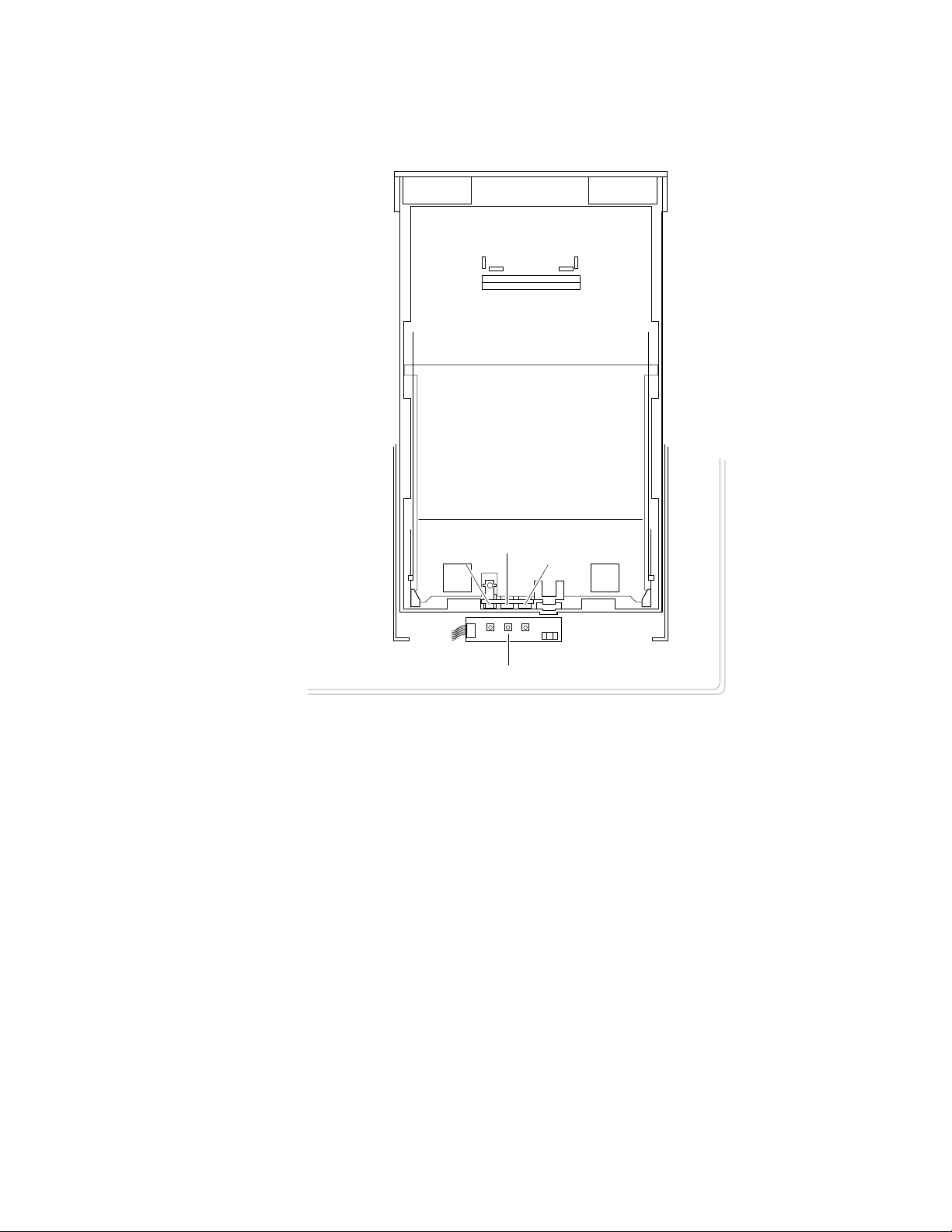
Print engine sensor, switch and solenoid locations 1-5
The front panel and its functions 1-7
The Phaser 540 rear panel 1-8
Tray switch sensors and actuators 1-11
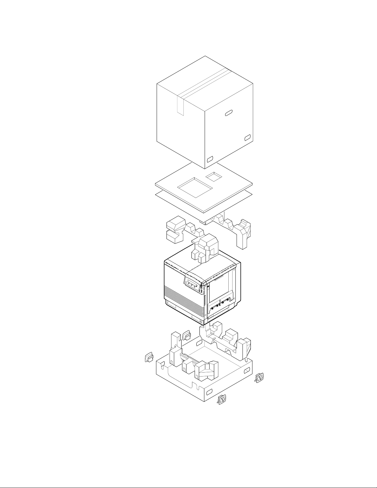
The Phaser 540 and its packaging 2-6
Connecting a SCSI hard disk drive to the Phaser 540 2-11
Connecting a CopyStation to the Phaser 540 2-12
Block diagram of the printer 5-2
Laser printing process overview 5-5
Pre-exposing the photoconductive belt 5-6
Electrostatic charging of the photoconductive belt 5-7
Laser exposure of the photoconductive belt 5-8
The laser scanner 5-9
Toner pickup 5-10
Toner transfer to the accumulator belt 5-11
Paper picking 5-12
Transferring toner to the paper 5-13
Fusing the toner to the paper 5-14
Print modes and printing dots 5-15
The power supply 5-17
The image processor graphics pipeline 5-19
Figure 6-1
Figure 6-2
xxii
Measuring the DC voltages (test points) 6-4
Door safety interlock switches 6-6
Phaser 540 Color Printer
Page 13

Figure 8-1
Figure 8-2
Figure 8-3
Figure 8-4
Figure 8-5
Figure 8-6
Figure 8-7
Figure 8-8
Figure 8-9
Figure 8-10
Figure 8-11
Figure 8-12
Figure 8-13
Figure 8-14
Figure 8-15
Figure 8-16
Figure 8-17
Removing cabinet covers 8-3
Removing cabinet covers 8-5
Removing the paper feeder and the paper tray sensor board 8-7
Removing the cartridge selector/eject unit 8-8
Removing the laser scanner 8-9
Removing the laser modulation board 8-10
Removing the power supply and the fuser installed switch 8-12
Replacing the power supply fuse 8-13
Removing the engine control, engine driver and charger sensor boards 8-15
Removing the main motor, paper-feed motor and cleaning board 8-17
Removing the toner cartridge drive unit, home position sensor and
the left door interlock switch 8-19
Removing the high-voltage board 8-20
Removing the pre-exposure lamp, pre-transfer lamp and toner auto-density sensor 8-22
Removing the image processor board 8-23
Installing RAM SIMMs 8-25
Installing a network card in the printer 8-26
Installing the code ROM SIMM 8-28
Figure 9-1
Figure 9-2
Figure 9-3
Figure A-1
Figure A-2
Figure A-3
Figure C-1
Menu map 9-2
Menu map 9-3
Checking the registration of the toner layers 9-10
Cabinet FRUs A-2
Cabinet FRUs A-3
The internal printer A-5
Wiring diagram C-1
Service Manual
xxiii
Page 14

Tables
Table 1-1
Table 1-2
Table 1-3
Table 1-4
Table 1-5
Table 1-6
Table 2-1
Table 2-2
Table 6-1
Table 6-2
Table A-1
Table A-2
Table A-3
Table A-4
Tray switch sensor combinations 1-10
Physical dimensions 1-12
Printer clearances 1-12
Functional specifications 1-13
Electrical specifications 1-13
Environmental specifications 1-14
Configuration page settings for the Phaser 540 2-14
Values for modifying the DEVPARAMS.PS file 2-28
Motor and solenoid resistances 6-7
Print engine service error codes 6-19
FRU parts list of the printer cabinet A-2
FRU part list of the printer cabinet A-3
FRU parts list of the exploded printer A-4
Supplies and accessories A-6
Table D-1
Test Pattern Generator DIP Switch settings for Phaser 540 D-4
xxiv
Phaser 540 Color Printer
Page 15
Chapter
1
General Information
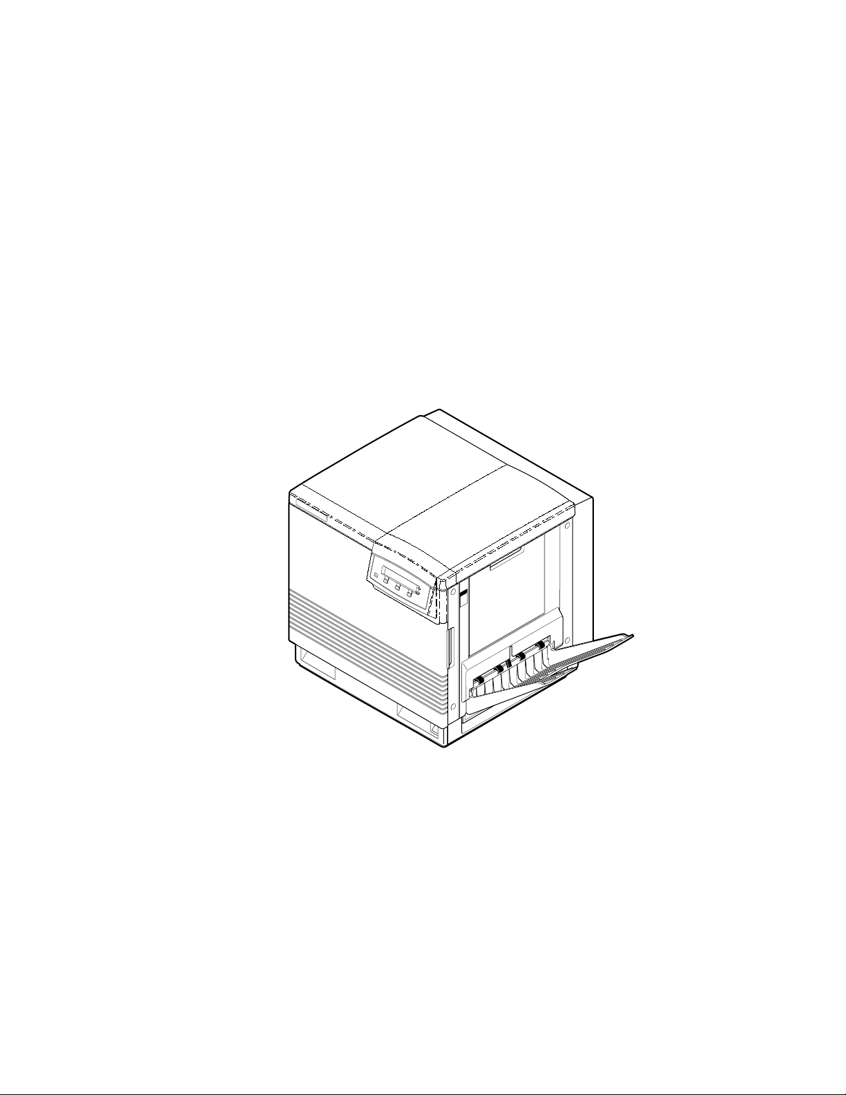
This service manual contains information useful for troubleshooting, repairing,
adjusting, and maintaining a Tektronix Phaser
Printers. This manual includes troubleshooting guides, adjustment procedures,
a field replaceable units (FRU) list and assembly/disassembly procedures for
selected FRUs. To ensure complete understanding of the product, we
recommend participation in Phaser 540 service training.
®
540 and Phaser
®
540 Plus Color
Figure 1-1 The Phaser 540 Color Printer
9013-01
Service Manual
1-1
Page 16

General Information
1
The Phaser 540 Color Printers
The Phaser 540 and Phaser 540 Plus Color Printers both combines a color laser,
continuous-tone print engine with an image processor supporting Adobe’s
PostScript Level 2 page description language (version 2015). The image
processor features a bi-directional parallel interface for host communication.
Optional network adapter cards to the image processor allow the printer to
communicate on networks using LocalTalk, serial, Ethernet or Token Ring
protocols. The Ethernet network card supports EtherTalk, Novell and TCP/IP.
With the Token Ring network card, the Phaser 540 Plus supports Toten Ring
protocols. The network cards are sometimes referred to as “smart cards”
because each houses its own processor for executing specific on-board protocols;
only data is transferred from the installed smart card to the printer’s image
processor board.
The printers each comes standard with 20 Mbytes of RAM which can be
supplemented with one or two additional 16-Mbyte RAM SIMMs. The printer
contains 39 standard, built-in fonts. The printer features a SCSI-compatible
interface to connect to an external hard disk drive for additional font storage.
An orderable option, the Phaser CopyStation can also be connected to the
printer’s SCSI port to give the printer the ability to optically copy color images.
The printer supports printing on A- and A4-sized paper and transparency film
from an A or A4-size tray. An optional two-tray second feeder (called the Lower
Tray Assembly) is available. The printer also supports manual feeding. The
Phaser 540 Plus also supports Legal-size paper in its Legal-size tray.
The printer prints at a user-selectable resolution of 300 dots-per-inch or
600 dots-per-inch. Color printing is at either 4 or 16 levels of color depending on
the amount of memory installed in the printer. After being idle for one hour the
printer switches into its Energy Star mode where it consumes less than 45 watts
of power. It “awakens” upon receiving data at any of its ports. The printer also
features a closed-loop image density sensor system that allows it to
auto-calibrate its color imaging so printing output remains consistent over the
life of the print engine and its consumable supplies.
RAM and printer capabilities
With additional RAM memory the printer’s capabilities increase:
■
With standard 20 Mbytes of RAM, the printer has a frame buffer of 16
Mbytes, an I/O buffer of 100 kbytes, an image pipeline color cache of
500 kbytes, and PostScript virtual memory of 3.6 Mbytes. With
standard 20 Mbytes of RAM, the printer can print 300 dpi
continuous-tone and 600 dpi bi-level images.
1-2
Phaser 540 Color Printer
Page 17
With 36 Mbytes of RAM, the printer has a frame buffer of 32 Mbytes,
■
an I/O buffer of 100 kbytes, an image pipeline color cache of 500
kbytes, and PostScript virtual memory of 3.6 Mbytes. With 36 Mbytes
of RAM the printer can print 300 or 600 dpi continuous-tone images
and has faster data throughput. With the additional RAM in the
Phaser 540 Plus, the scan-to-print start time of the Phaser CopyStation
is reduced to about 65 seconds.
■
With a maximum 52 Mbytes of RAM, the printer has a frame buffer of
32 Mbytes, an I/O buffer of 1 Mbytes, and image pipeline color cache
of 2 Mbytes, and PostScript virtual memory of 16.8 Mbytes.
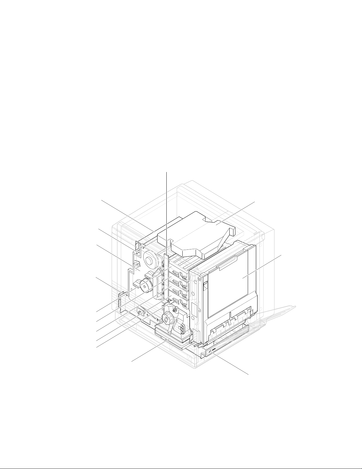
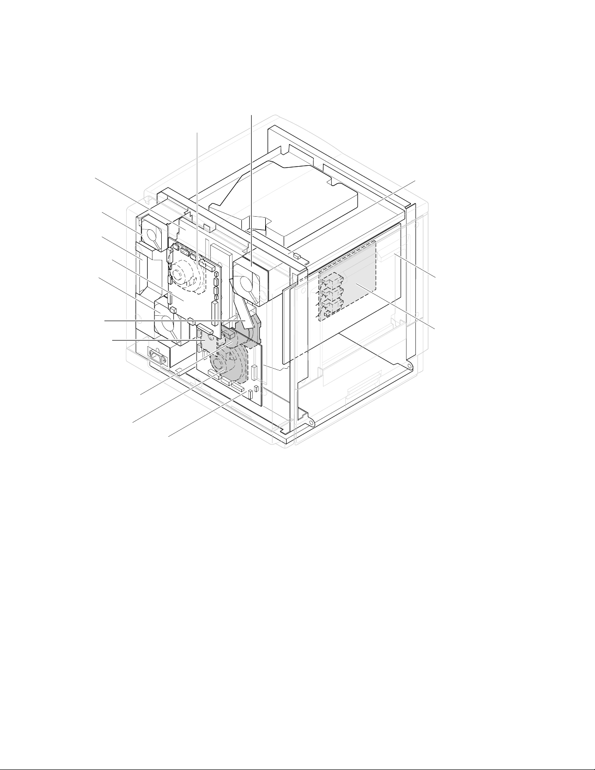
Print engine assemblies
Toner level
sensor board
General Information
1
Pre-exposure lamp
Imaging unit
Paper feeder
Black toner cartridge
Yelllow toner cartridge
Magentatoner cartridge
Cyan toner cartridge
Pre-transfer lamp
Ozone filter
Fuser
Laser scanner
Toner cartridge
selector/paper
exit unit
ER
P
A
P
A4
Paper tray
9013-02
Figure 1-2 Print engine major components
Service Manual
1-3
Page 18
General Information
1
Toner cartridge
drive unit
Power
supply fan
Power
supply unit
Engine
control board
Fuser fan
Charger
sensor board
Cleaning board
Toner
cartridge
motor
Ozone fan
Laser driver board
Image processor
board
High voltage board
Main motor
Paper feed motor
Engine driver board
Figure 1-3 Print engine components (continued)
9013-03
1-4
Phaser 540 Color Printer
Page 19
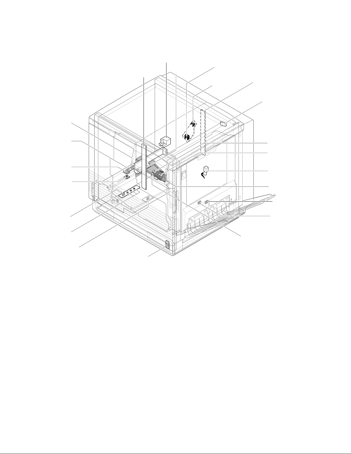
Manual feed
sensor
Registration
sensor
Transparency
sensor
(transmitter)
Transparency
sensor
(receiver)
Toner level
sensors
(transmitters)
Accumulator belt
home position sensor
Image density
sensor
Scorotron
charger
sensor
Pre-transfer
charger
sensor
General Information
Toner level sensors
(receivers) are mounted
inside the toner cartridge
driver unit
Front right door
opened switch
Transfer waste
bin sensor
Transfer roller
position sensor
Fuser-installed
switch
Left door opened
switch
1
Paper low
sensor*
Paper tray
type sensors
Paper jam
sensor
*Unused by image processor
Power switch
Figure 1-4 Print engine sensor, switch and solenoid locations
These sensors are not illustrated:
■
The photoconductive belt position sensor. This optical sensor marks
the home position of the photoconductive belt. It is mounted inside
the customer-replaceable imaging unit.
The photoconductive belt toner disposal bin full sensor. It is mounted
■
inside the customer-replaceable imaging unit. This ultrasonic sensor
determines if one of the imaging unit’s two waste toner bins is full
which, if true, would impair print quality. Under ordinary
circumstances, neither waste toner bin should fill up before the
imaging unit’s life is expired.
Paper-exit
sensor
Fuser-exit
sensor
Paper-empty
sensor
9013-04
The logic state of paper low sensor is not monitored or used by the image
processor.
Service Manual
1-5
Page 20

General Information
1
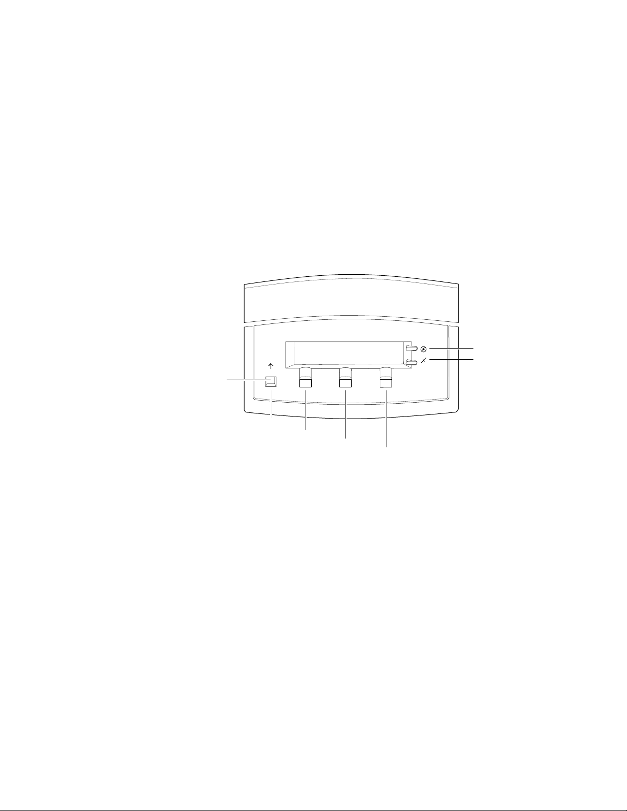
Front panel
These front panel features are found on the printer:
■
A two-line, 24-character LCD and two LEDs
Four push buttons
■
LCD
The LCD serves two purposes: displaying current controller and print
engine status information and displaying an interactive menu. Status
information includes controller status such as
Printing . Print engine status includes messages such as Out of paper ,
Paper Jam , and Out of toner . The interactive menu can only be entered
while the print engine and controller are idle. The interactive menu allows the
user to review and change certain NVRAM, I/O ports and peripheral
parameters. Using the front panel to review and change parameters is discussed
in Chapter 9, “Checks and Adjustments.”
Ready , Receiving data and
Buttons
cancel an operation while in the interactive menu. The functions of Buttons 2, 3
and 4 are defined by the particular menu or function being displayed on the
LCD display. The bottom row of the LCD labels the current function of each
button.
In addition, pressing the buttons as you turn on the printer enables certain
diagnostic modes:
■
■
■
The Chapter 9 topic, “Resetting NVRAM” on page 9-9 explains how to use the
front panel buttons to reset the NVRAM to its factory default values.
Button 1, the left-most button, is labeled the Exit key and is used to
Pressing and holding Button 1, as you turn on the printer, skips
power-up diagnostics (except for a brief kernel test) and proceeds to
PostScript startup.
Pressing and holding Button 2, as you turn on the printer, executes
extended diagnostics.
Pressing and holding Button 3, as you turn on the printer, executes
interactive service tests. These are described in “Printer
self-diagnostics” on page 9-6.
1-6
Phaser 540 Color Printer
Page 21
On
General Information
LEDs
The Power LED indicates the printer has +5 VDC available for its logic
control boards.
The
Error LED has three indications:
■
Off indicates that no errors have been detected.
■
indicates a warning to the user. An explanatory message, such as
Low Paper , is displayed on the LCD.
Blinking indicates an error has been detected. An error message, such
■
Paper Jam at Output , is displayed on the LCD. Error codes
as,
are listed and explained in the Section 6 topic, “Error messages” on
page 6-19.
1
Exit
Exit
Button 1
Button 2
Button 3
Button 4
Figure 1-5 The front panel and its functions
Power
Error
9013-06
Service Manual
1-7
Page 22
General Information
1
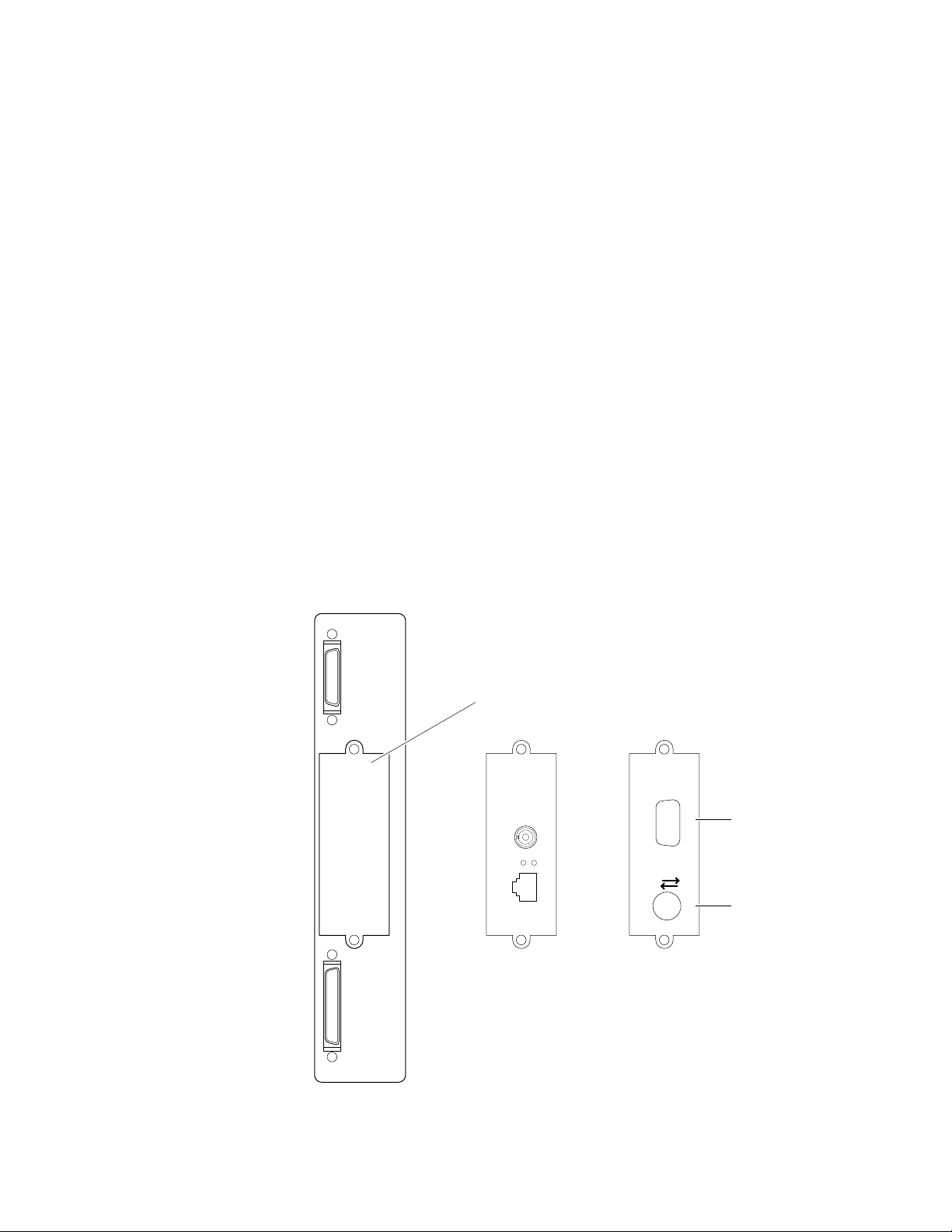
Rear panel
Connectors
The rear panel of the Phaser 540 printer features the host interface connectors to
the printer. It includes the following connectors:
Standard parallel (high-density connector).
■
■
SCSI high-density connector (font hard disk drive or
Phaser CopyStation only).
With the addition of a network card, the printer can feature either of these
groups of connectors:.
■
ThinNet (10base2) and Twisted Pair (10baseT) Ethernet connectors.
This is Option P1 and P2.
■
RS-232 serial and LocalTalk connectors. This is Option P2
Unshielded Twisted Pair (10baseT) and shielded Twisted Pair (DB-9)
■
Token Ring connectors. This is Option P4.
The figure below illustrates the rear panel.
Parallel
Smart card slot
for network card
Phaser™ Share
Ethernet Card
10Base2
Link
RX
TX
10Base-T
LocalTalk/Serial Card
Phaser™ Share
Serial LocalTalk®
RS-232
serial
LocalTalk
1-8
Figure 1-6 The Phaser 540 rear panel
Phaser 540 Color Printer
SCSI
Option
P1
P2
Option
P3
9013-05
Page 23

on
on
Network card LEDs
The Ethernet network card has two LED indicators:
■
■
Note
General Information
TX indicator (yellow); blinks while data is transmitted to the host. The
LED is off while no data is being sent.
Twisted Pair (10baseT). RX indicator (green); blinks while the
network card is receiving data. The LED is
being received. If the LED is
hardware) has occurred at the network hub.
ThinNet (10base2). RX indicator (green); blinks while the network
card is receiving data. The LED is
received. If the LED is
has occurred at the network hub.
Do not use both Ethernet connectors at the same time. If both are used
the 10base2 line is ignored.
on steady , then a problem (probably hardware)
off steady , then a problem (probably
off stead y while no data is being
on steady while no data is
1
Test print button
The Token Ring network card has two LED indicators:
■
Connection (yellow); off when the printer is not inserted into the Token
blinks while the printer is attemping to insert itself into the Token
Ring,
Ring,
Ring Speed (green); off when the card is set for 4 megabits per second
■
(MBPS),
When both LEDs blink, a network card failure has occured.
■
In the center of the rear cabinet panel is the test print button. Pressing this
button while the printer is idle causes the print engine to print a built-in test
print. The print is made independently of the image processor board.
when the printer is properly inserted in the ring.
when the card is set for 16 MBPS.
Service Manual
1-9
Page 24

General Information
On
1
Health LED
A health LED indicates the status of the image processor board. The health LED
is mounted on the image processor board and is viewable through the grill
behind the manual feed tray. (The grill is the removable RAM SIMM options
cover.) Once the PostScript code is loaded into memory and the image processor
is initialized and running, the image processor blinks the LED at a one-second
rate.
Blinking (at a steady rate): The printer is operating normally. The LED
■
blinks irregularly during power-up self-diagnostics.
If a soft error occurs, the image processor board operates, but in a
reduced capacity. Soft failures include failure of expansion memory
SIMMs or any of the interface ports. When a soft error occurs, the
printer automatically prints a startup page listing the error.
■
or Off : A hard error condition has occurred that would keep the
image processor board from operating.
Media tray type sensing
The combinations of the three tray sensors “tell” the print engine what type of
paper tray is installed. The tray sensors are located on the left-side interior of
the paper tray slot. Sensor actuators are attached to the bottom end of the tray to
close the appropriate sensor. There are four tray types:
■
Letter (A-size) paper
Letter (A-size) transparency film
■
■
Metric Letter (A4-size) paper
■ Metric Letter (A4-size) transparency film
■ Legal-size paper (Phaser 540 Plus)
Table 1-1 Tray switch sensor combinations
Left switch Middle switch Right switch Tray type
Closed Open Open Letter (A-size) paper
1-10
Closed Closed Open Letter (A-size) transparency film
Open Open Closed Metric Letter (A4-size) paper
Closed Open Closed Metric Letter (A4-size) transparency film
Open Closed Open Legal-size paper
Phaser 540 Color Printer
Page 25
General Information
1
Sensor actuators
Middle
Left
Right
Tray sensors
Figure 1-7 Tray switch sensors and actuators
9013-40
Service Manual
1-11
Page 26

1
General Information
Specifications
Table 1-2 Physical dimensions
Dimensions Specification
Height:
Width: 48.3 cm (19 in.) With output tray: 69.6 cm (27.4 in.)
Depth: 48.3 cm (19.5 in.)
45.7 cm (18 in.) With Lower Tray Assembly: 68.6 cm (27 in.)
Weight: Approximately 53.3 kgs (117 lbs.) with Lower Tray Assembly
and consumables installed.
Approximately 39.1 kgs (86.2 lbs.) without Lower Tray
Assembly.
Table 1-3 Printer clearances
Clearances Specification
Top: 7.6 cm (3 in.)
Left: 7.6 cm (3 in.)
Right: 10.2 cm (4 in.) for handling the output tray
Front: Unlimited for removal of consumable
Rear: 15.3 cm (6 in.) for connecting computer cable and pow er cord
Bottom: No obstruction under printer that could block its cooling vents.
Mounting surface
flatness:
Within 2 degrees of horizontal with all four feet in contact with
the table surface.
1-12
Phaser 540 Color Printer
Page 27

General Information
Table 1-4 Functional specifications
Characteristic Specification
Printing process Electro-photographic, four color (CMYK) transfer printing
1
Color medium Four toner cartridges each contain one of four colors: cyan,
Addressability Standard mode: 300 x 300 dots-per-inch text and graphics
Printing speed Time from paper-load to paper-eject:
Minimum printing
margins
Usable paper A-size (letter) and A4-size (Metric letter) and Legal-size of a
Paper tray capacity 250 sheets using 20-lb. paper. 100 sheets of transparency
magenta, yellow or black. The toner is a nonmagnetic,
monocomponent contact medium.
Enhanced mode: 600 x 600 dpi text and graphics
Four-color 3.5 pages per minute at 300 dpi
paper: 1.75 pages per minute at 600 dpi
Monochrome: 14 pages per minute at 300 dpi
7 pages per minute at 600 dpi
Four-color transparency: 1.3 pages per minute at 300 dpi
Print times do not include image processing time, which can
vary depending on image complexity.
All sides, 5 mm (0.2 ins.).
good quality, or premium laser printer or copier paper.
film. The optional Lower Tray Assembly also uses trays with
the same capacity.
Table 1-5 Electrical specifications
Characteristic Specification
Primary line voltages 87 to 128 VAC (115 VAC or 100 VAC nominal); 174 to 260
Primary voltage
frequency range
Power consumption 60 watts (fuser off), 850 watts (fuser on) during Ready state,
Primary voltage fusing 110 VAC configuration – 10 amp
Secondary DC voltages Image processor:
RF emissions Both 110 and 220 VAC-configured instruments pass these
VAC (220 VAC nominal)
47 to 63 Hz
950 watts during Warm-up state, 45 watts during Energy Star
state
220 VAC configuration – 6.3 amp
+ 5 VDC ± 0.25 (1A minimum, 6 A maximum)
± 12 VDC ± 0.6 (100 mA max)
Print engine:
+ 5V ± .25 (2.2 A max)
+ 12V ± .25 (0.4 A max)
- 12V ± .25 (0.1 A max)
+ 24V ± .25 (3.0 A max)
standards: FCC Part 15 Class B
VDE Class B
EN55022 (CISPR 22) Class B
VCCI (CISPR 22) Class B
Service Manual
1-13
Page 28

1
General Information
Table 1-6 Environmental specifications
Characteristic Specification
Temperature
Operating
Non-operating
Storage
Humidity
Operating
Non-operating
10o to 32.5o C (50oto 91oF)
o
0
to 40o C (32o to 104o F)
o
-20
to 60o C (-4
o
to 140o F)
Media should be acclimated 24 hours before using in the
printer.
10 to 80% relative humidity, non-condensing
10 to 90% relative humidity, non-condensing
Media should be acclimated 24 hours before using in the
printer.
Altitude
Operating
Non-operating
Vibration/shock
Operating
Non-Operating
(vibration)
Non-operating (shock)
Acoustic Noise
(operating)
o
0 to 2500 m (8,000 ft.) at 25
C
0 to 15000 m (50,000 ft.)
(Fuser maximum 4000 m (13,300 ft.)
May drop any side or corner 50 mm (2 in.) without impairment
of subsequent operation.
On five mutually perpendicular axes: 0.5 g, 25-minute sweep,
5 to 200 to 5 Hz, 100 to 200 sec./sweep cycle. No resonant
frequencies below 50 Hz.
30 g, trapezoidal flared pulse, 20 msec each axis.
Aver age sound le vel (LEQ) is less than 53 dbA. Peak noise in
standby mode is 47 dbA.
1-14
Phaser 540 Color Printer
Page 29

Regulatory specifications
The printer is a recognized component in conformance with the following
regulatory standards:
■ The packaged product meets ASTM D4169-86 and ASTM D4728-87
Transportation Standards.
■ Listed UL 1950 Information Processing and Business Equipment.
■ Certified CSA C22.2 No. 950 Safety of Information Technology
Equipment, Including electrical Business Equipment.
■ GS licensed IEC 950 (1991) Second Edition; EN60950 Information
Processing and Business Equipment.
■ VDE 0871/6.78 (Class B) Regulation for the Radio Frequency Interface
Suppression of High Frequency Apparatus and Installations.
■ VDE 0875, Regulation for RFI Suppression of Electrical Equipment
and Installations
General Information
1
■ EN55022 (CISPR 22) Class B
VCCI (CISPR 22) Class B
■ FCC Class B (for 115 VAC equipment) pursuant to Sub-part J
of Part 15.
Service Manual
1-15
Page 30

Page 31

Chapter
2
Installing the Printer and
Drivers
This chapter discusses installing the printer and its drivers as a part of the S0
printer installation option. Tektronix Service Option S0 consists of three main
functions detailed in this and the next two chapters of this manual:
■
Chapter 2 “Installing the Printer and Drivers.” The first portion of
installation instructions, this chapter, consists of five basic processes:
Pre-installation interview. This is a phone interview to verify that the
■
customer is ready for the printer. The interview verifies that the
customer has a suitable place for the printer with the proper
environment. The call also verifies that any assistance, such as network
system administration, will be available for the scheduled installation
and that all necessary cables will be available.
■
Unpacking. This is the procedure for taking the printer out of its
shipping box.
Testing. This checks that the printer works properly prior to connecting
■
it to a host computer.
Cabling and configuring. This discusses setting up the printer for
■
communicating to the appropriate host computers.
■
Loading drivers. This covers installing software on the host computers
and configuring the host applications to drive the printer.
Following these steps, proceed to Chapter 3 and then Chapter 4.
■
Chapter 3 “Verifying the Printer and Host Connections” explains how
to verify that the printer, the host driver and the connection between
them functions correctly.
■
Chapter 4 “Key Operator Training” gives a procedure for training the
customer to use and care for the printer.
Service Manual
2-1
Page 32

Installing the Printer and Drivers
2
Pre-install questions for customers
Prior to installing the printer, you should contact the customer and verify that he
or she has prepared an appropriate location for the printer. You will also want to
ensure that you have all the information you need to install the printer at the
customer's site.
Ask the customer the following:
Customer's name
Address ___________________________________________________________
Phone number _____________________________________________________
What type of computers will be networked with the printer?
■
■
Will this printer be connected directly to a host either:
■
What kind of network environment will the printer be installed into?
In the event that the printer is to be installed into a network
■
environment, will a network administrator be available to help in
assigning network names and addresses for the printer?
Administrator's name__________________________
Phone Number________________________________
___________________________________________________
❏
PC ______________
❏
UNIX____________
❏
serial
dware Protocols
Har
❏
LocalTalk
❏
ThickNet (10Base5)
❏
ThinNet (10Base2)
❏
Twisted Pair (10BaseT)
❏
Macintosh___________
❏
other _______________
❏
parallel?
❏
EtherTalk
❏
TCP/IP
❏
Novell NetWare
❏
TokenRing
❏
other _______________
2-2
■
In the event that the printer is to be installed in a TCP/IP network, has
the network administrator assigned printer name and IP addresses for
the printer? Printer Name _____________________
What software application packages will be used with the printer?
■
Some applications require special printing utility files.
_____________________________________________
■
Will the application(s) and sample files be available at the time of the
installation to send test files to the printer?________
■
Will a SCSI font disk be installed on the
printer?
Phaser 540 Color Printer
Printer IP address__________________
Net Mask _________________________
Broadcast address _________________
Gateway__________________________
______________________________________
Page 33

Installing the Printer and Drivers
For installations using the printer’s Ethernet interface you should
■
inform the network administrator of the printer's preconfigured
Ethernet address. It is printed on the startup page as well as printed
on a label placed inside the front door.
Does the customer have the appropriate power outlet available? The
■
printer should be installed on a minimum 15 amp circuit. The
printer's AC power input is ordered for:
110 VAC (87 to 128 VAC)
220 VAC (174 to 250 VAC)
■
Did the customer order the correct power cord?
_______ U.S. Standard (161-0104-00
_______ European Option A1 (161-0104-06)
_______ United Kingdom Option A2 (161-0066-10)
_______ Australian Option A3 (161-0104-05)
_______ Swiss Option A5 (161-0154-00)
■
Customers must provide the particular interface cable they need to use
with the printer. Customers can purchase the following from the
Tektronix Graphics Supplies Order Desk by calling 1-800-835-6100.
2
■
Parallel cable, DB25 male to Centronics 1284C 012-1468-00
Serial, 9-pin to 9-pin, 3 m (10 ft.), null modem 012-1379-00
■
■
Serial, 9-pin to 25-pin, 3 m (10 ft.), null modem 012-1380-00
For AppleTalk installations,
customers must provide the appropriate
network adapter to the printer's 9-pin circular LocalTalk connector.
Customers can obtain an adapter from their dealer.
The printer requires the following environmental conditions:
■
Temperature: 10 to 32.5
Humidity: 10 to 80% relative humidity, non-condensing
■
■
Power: 10 A at 110 VAC
o
C (50 to 91
o
F)
6.3 A at 220 VAC
Clearances: A space measuring 107 cm wide by 50 cm deep by 46 cm high
(42 ins. wide by 19.5 ins. deep by 18 ins. high). The width of the printer accounts
for enough clearance to install the paper tray and open the manual feed tray.
Add an additional 23 cm (9 ins) to the height if a lower tray assembly is to be
installed.
Weight support: 39.1 kgs (86.2 lbs.) without the Lower Tray Assembly and
installed consumables. Approximately 53 kgs (117 lbs.) with the Lower Tray
Assembly.
Service Manual
2-3
Page 34

Installing the Printer and Drivers
2
Driver software must be installed on the host computer to use the printer to its
fullest potential. A host computer must meet the following conditions:
Mac
Mac II, Performa, Centris or Quadra, PowerMac or PowerBook.
■
■
System 6.0.7 or later
4 Mbytes RAM
■
PC
■
IBM AT, PS/2 or compatible, with a 386 or later CPU, a 5.25- or
3.5-inch floppy drive, and a hard disk drive, 2 Mbytes RAM
DOS system
DOS 3.1 or later
An application that supports color PostScript or HP-GL
Windows systems
Windows 3.1
2 Mbytes of hard disk space
Workstation
■
UNIX workstations: The X Window System,
SUN workstations: Solaris 1.1 (BSD), Solaris 2.x (Sys V, optional LPD
support required)
DEC: Ultrix, VMS, OpenVMS
HP: HP-UX
SGI: IRIX
IBM RS6000: AIX (optional LPD support required)
750 kbyte hard disk space for files
■
Based on the results of the pre-install interview with the customer, you may
wish to access the Tektronix Highly Automated Library (HAL) at 1 800 835-6100
or EuroHAL for articles that may help with installing the printer into a
customer's network. You can call HAL 24 hours a day, 7 days a week. The
articles can be faxed to you in just minutes. HAL may also have articles that
may be of interest to your customer, such as printing from a specific application.
(This is a good way of introducing the HAL system to the customer.)
2-4
Phaser 540 Color Printer
Page 35

Unpacking
Printer inventory
Installing the Printer and Drivers
Power cord
■
■
User manual
Quick Start installation instructions
■
■
TekColor™ Care envelope (product registration enclosed)
Quick Reference Card
■
■
Supplies information sheet
Printer driver reference manual and diskettes
■
■
Optional Phaser Share network user manual and diskettes
2
Accessory box
Standard paper tray, A or A4
■
■
Output tray
Four toner cartridges (cyan, magenta, yellow and black)
■
■
Imaging unit
Fuser
■
■
Phaser 540 media sampler
Note
Interface cables must be ordered separately.
Service Manual
2-5
Page 36
Installing the Printer and Drivers
2
2-6
9013-07
Figure 2-1 The Phaser 540 and its packaging
Phaser 540 Color Printer
Page 37

Setting up the printer
Installing SIMM memory
The standard configuration for a Phaser 540 includes 20 Mbytes of memory. Two
optional SIMMs can be added for a total of 52 Mbytes of memory. The optional
SIMM installation order is as follows:
■
connector P81 = SIMM 1
connector P82 = SIMM 2
■
Refer to the Chapter 8 topic, “Installing RAM SIMMs” on page 8-24.
Installing a network card
Network support is provided via two optional Phaser Share Network Interface
plug-in cards.
Installing the Printer and Drivers
2
The LocalTalk/Serial Interface Card support AppleTalk/LocalTalk
■
protocols and RS-232 serial connectors.
The Ethernet Interface Card supports EtherTalk, Novell NetWare and
■
TCP/IP protocols.
The Token Ring Interface Card supports TokenRing protocols
■
(Phaser 540 Plus only)
Refer to the Chapter 8 topic, “Installing a network card” on page 8-26.
Service Manual
2-7
Page 38

Installing the Printer and Drivers
1.
2.
3.
2
Cabling the printer
Note
This topic explains making a hardware connection between the printer and its
host computer, setting the communication parameters for the printer's serial and
parallel ports to be compatible with the user's host computer and driver
installation. This topic is divided into three main parts: Macintosh, PC, and
workstation.
Carry spare serial and parallel cables. You can use them if you
encounter a defective cable or as an alternate means of testing the
printer-to-host communications.
Connecting the printer to a Macintosh
A direct connection between the printer and a Macintosh is through the printer's
serial port. Since this is a highly unlikely connection for a customer to use
because of the serial port’s slow data speed, it is not discussed. A networked
connection for a Macintosh will most likely be either a LocalTalk network or an
Ethernet network.
LocalTalk connection to a Macintosh
Note
For a LocalTalk network, the Serial/LocalTalk network card must be
installed.
Turn off the printer. LocalTalk protocol requires you to attach the
LocalTalk cable with the printer powered
For a LocalTalk network connection, attach the network adapter to the
printer's LocalTalk port. Then attach the network cable (LocalTalk
cable, PhoneNet, etc.) to the network adapter.
Turn on the printer.
off .
Ethernet connection to a Macintosh
Note
1.
2.
For an Ethernet connection, the printer must have the Ethernet option
card installed.
Turn off the printer. EtherTalk protocol requires you to attach the
Ethernet cable with the printer powered off.
Attach the network cable (ThinNet or TwistedPair) to the printer’s
appropriate Ethernet connector. Use only one connector.
2-8
Phaser 540 Color Printer
Page 39

3.
Turn on the printer. During the printer's boot-up process, the printer's
network name is displayed in the Mac's Chooser and its node address
is resolved with the network. If the network features multiple zones,
the network router assigns the printer a default zone name. The
printer’s configuration page lists the name. The topic “Printing the
configuration page” on page 9-4 explains printing this page.
Connecting the printer to a PC
Direct connection to a PC
1.
Turn off the printer. Turn off the PC.
2.
Attach the parallel interface cable to the host computer. Attach the
other end to the printer. Alternatively, attach the serial cable to the
host computer's serial port. Attach the other end to the printer's serial
port. The serial connections requires that the Serial/LocalTalk
network card be installed.
Installing the Printer and Drivers
2
3.
Turn on the printer and the PC.
Networked connection using the Ethernet port
Note
In Novell NetWare networks, the printer is connected to the network in the
same manner as the workstations using an Ethernet connection.
1.
2.
3.
For an Ethernet connection, the printer must have the Ethernet option
card installed.
Turn off the printer.
Connect the interface cable to the printer’s ThinNet or TwistedPair
Ethernet connector. Use only one connector.
Turn on the printer.
Networked connection using the Token ring port
Note
For Token Ring networks, the Phaser 540 Plus must have the optional
Token Ring network card installed.
1.
Turn off the printer.
2.
Connect the interface cable to the printer’s appropriate Token Ring
connector.
3.
Turn on the printer.
Service Manual
2-9
Page 40

2
Installing the Printer and Drivers
Connecting the printer to a workstation
Direct connection to the workstation
1.
Turn off the printer. Turn off the host computer.
2.
Attach the parallel interface cable to the workstation. Attach the other
end to the printer. Alternatively, attach the serial cable to the
workstation's serial port. Attach the other end to the printer's serial
port. The serial connections requires that the Serial/LocalTalk
network card be installed.
3.
Turn on the printer and the computer.
Networked connection to a workstation
Note
1.
2.
3.
For an Ethernet connection, the printer must have the Ethernet option
card installed.
Turn off the printer.
In the case of an Ethernet network, connect the interface cable to the
printer’s Ethernet ThinNet or TwistedPair connector. Use only one
connector.
Turn on the printer.
Networked connection using the Token Ring port
Note
1.
2.
For Token Ring networks, the Phaser 540 Plus must have the optional
Token Ring network card installed.
Turn off the printer.
Ensure the transmission speed jumper on the printer’s Token Ring
network card is set for the speed of the token ring network. Not
installed set the card for 16 Mbps (the most common configuration);
installed set the card for 4 Mbps.
2-10
3.
Connect the network interface cable to the printer’s appropriate Token
Ring connector.
4.
Turn on the printer.
Phaser 540 Color Printer
Page 41

Installing the Printer and Drivers
Connecting an optional SCSI hard disk drive to the printer
Perform this procedure if the customer has a hard disk drive available for font
storage. Otherwise, continue to the next procedure.
1.
Make sure that the printer and the SCSI disk drive are turned off.
2.
Attach the SCSI cable to the printer's SCSI port.
3.
Attach the other end of the SCSI cable to the SCSI drive.
4.
Attach a terminator to the SCSI drive's second connector. (This is not
required if the disk drive is internally terminated.)
2
Terminator
SCSI cable
SCSI drive
Figure 2-2 Connecting a SCSI hard disk drive to the Phaser 540
5.
Select the desired SCSI address (0 through 6) on the SCSI drive. The
printer’s SCSI address is 7.
6.
Turn on the disk drive first, and then turn on the printer.
7.
Refer to the Phaser 540 Drivers and Utilities Printing Reference for details
on formatting the SCSI disk, controlling Sys/Start job files, and using
the LaserWriter Utility to load fonts onto the disk drive.
9013-09
Service Manual
2-11
Page 42

2
Installing the Printer and Drivers
Connecting the optional CopyStation to the printer
Perform this procedure if the customer has purchased a CopyStation.
Otherwise, continue to the next procedure. The CopyStation may be
“daisychained” with one or more SCSI drives being used for font storage. Be
sure that each SCSI device uses a unique SCSI address (0 through 4). Installing a
CopyStation is fully explained in the Phaser CopyStation User Manual.
1.
Make sure that the printer and the SCSI disk drive are turned off.
2.
Attach the CopyStation’s SCSI cable to the printer's SCSI port.
3.
Attach the other end of the SCSI cable to the CopyStation’s SCSI port.
CopyStation
SCSI cable
Figure 2-3 Connecting a CopyStation to the Phaser 540
Note
4.
5.
The CopyStation uses two SCSI address: 5 and 6. Make sure that
any connected SCSI hard drive does not use these addresses.
Turn on the CopyStation (and any hard drives) first, and then turn on
the printer.
Refer to the Phaser CopyStation User Manual for details.
9013-59
2-12
Phaser 540 Color Printer
Page 43

Turning on the printer
The startup page
When you turn on the printer, it executes a series of self-tests to determine if
there are any problems with the PostScript interface. After running self-tests, the
printer prints a startup page if it has not been disabled. After running self-tests
and printing the startup page, the printer is ready for operation. A front panel
menu item allows you to enable or disable the startup page.
The startup page provides you with valuable information about the printer:
■ Printer name
■ Fonts
■ Ports (serial, parallel, LocalTalk, Ethernet, Token Ring)
■ Ethernet protocols
Installing the Printer and Drivers
2
■ TekColor corrections and print quality mode
■ Pages printed
■ RAM installed
■ Tektronix version firmware level
■ Print engine firmware level
■ Adobe version software level
■ Printer SCSI ID
■ Authorization code
■ SCSI disk attached
■ Phaser CopyStation attached
If the printer detects a non-fatal error at power-up, the startup page prints with
an error message. This is true, even if the startup page has been disabled. The
printer will still force a print to report the error.
Message Description
Parallel, SCSI or Network card port failed The named port is not working. The other
x
DRAM SIMM
failed The optional memory SIMM x is not
ports can still be used.
working. In this message,
number of the SIMM that failed (1 or 2).
Since the printer’s base memory is still
working, the printer can still be used, but
large images may not print, fonts may not
download, and throughput may suffer.
x
indicates the
Service Manual
2-13
Page 44

2
Installing the Printer and Drivers
The configuration page
To provide further diagnostic information, the printer is able to print a
configuration page. The configuration page lists the values the printer stores in
its NVRAM. These values can be informative when troubleshooting the printer,
particularly networked operations. Refer to the Chapter 6 topic “Printing the
configuration page” on page 9-4 for details on printing the configuration page.
A downloadable PostScript utility, found on the Drivers and Utilities diskette,
also allows you to print the configuration page.
The configuration page gives you the following information:
■ General information about the printer, such as page count, the
programmed name, Ethernet address, the TCP/IP authorization code
(if loaded), timeouts, number of fonts, and total memory
■ Color settings such as Finepoint and Vivid Color.
■ Serial port settings
■ Parallel port settings
■ LocalTalk port settings
■ EtherTalk settings
■ Token Ring settings
■ TCP/IP settings
■ Novell NetWare settings
Table 2-1 Configuration page settings for the Phaser 540
Parameter Description Saved
in
NVRAM
Printer type The name of the product. yes Phaser 540
Printer name The current name of the printer as seen
on a network
Pages printed Total number of print jobs processed
through the image processor.
yes <printer type>
yes 0
Default Limits or alternate choices
same as the
name of the
product
Any name defined by the
customer up to 31 characters
in length
Startup page
enabled
Ethernet
address
2-14
Indicates if the printer prints a startup
page upon power-up.
A unique number for each
Ethernet-capable printer.
Phaser 540 Color Printer
yes No Yes
yes Hardware-
dependent.
Legal values
have the form
xx:xx:xx:xx:xx:xx
Page 45

Table 2-1 Configuration page settings for the Phaser 540 (cont'd.)
Installing the Printer and Drivers
2
Parameter Description Saved
in
NVRAM
Authorization
code
PostScript
version
Tektronix
version
Fonts in ROM Number of font stored in the printers
Job Timeout Amount of time a job can take to
Wait Timeout Amount of time the image processor
Manual Feed
Timeout
Upper media Type of media believed to be installed in
A unique number downloaded to the
printer (in the field or at the factory) to
enable TCP/IP protocols.
Firmware level of the PostScript
interpreter code.
Firmware level of the printer engine
code.
ROM memory.
process.
waits for additional data from a host.
The amount of time the printer waits for a
user to manually insert sheet of media
for a manual feed print job.
the upper or main tray.
yes <not authorized> Valid code number in the
yes 0 seconds Any value denoted in seconds.
yes 40 seconds Any value greater than 14
yes 60 seconds Any integer value; 0 means
yes Paper Transparency
Default Limits or alternate choices
format
0000-0000-0000-0000-0000-0
000-0000
39 39
0 means unlimited amount of
time
denoted in seconds; 0 means
unlimited amount of time
unlimited amount of time
Manual media Type of media believed to be feed in the
Media tray Indicates the default media tray. yes Upper Middle, Lower, Auto
Media type Type of media assumed to be in each
Energy Star
time-out
RAM memory Total amount of RAM on the image
Color
Correction
Print quality
mode
Phaser™
Share
LocalTalk port
interpreter
LocalTalk
Printer T ype
manual feed tray.
printer tray and the manual feed tray.
Amount of idle time allowed before the
printer switches to a low energy power
down mode.
processor board.
Indicates the type of color adjustments
used to simulate different color uses.
Indicates the quality mode to use for
image printing
Indicates the type of Phaser Share
network card installed
Indicates the type of interpreter in use at
the port
Indicates the type of printer installed at
the port
yes Paper Transparency
yes Paper Transparency
yes 1 hour Any integer from 1 to 90
denoting hours.
20 Mbytes 36 or 52
yes None User Defined, Vivid Color,
Simulate Display, SWOP
Press, Euroscale Press,
Commercial Press,
Monochrome, Raw RGB
Colors, Raw CMYK Colors
yes Standard Enhanced, Fast
no none LocalTalk/Serial, Ethernet,
Token Ring
yes PostScript Level 2 Not installed, Disabled,
<interpreter>
yes LaserWriter Any string 32 characters in
length or less
Service Manual
2-15
Page 46

2
Installing the Printer and Drivers
Table 2-1 Configuration page settings for the Phaser 540 (cont'd.)
Parameter Description Saved
in
NVRAM
LocalTalk Node Indicates the LocalTalk network node
Parallel Port
interpreter
Parallel Port
Encoding
Parallel Port
back channel
Handshaking Setting whether unidirectional or
Serial Port
interpreter
Serial port
encoding
Serial port
speed
Serial port
flagging
number of the printer
Indicates the type of interpreters in use
at the port
Indicates the type of data encoding the
parallel port is inspecting
The device used for standard output and
standard error.
bidirectional communication is used.
Indicates the type of interpreters in use
at the port.
Data byte encoding for communication. yes ASCII Binary, Raw, TBCP
Baud rate. yes 9600 38400 (product dependant),
Hardware or software flagging. yes XonXoff DTR, DTR low, Etx Ack,
no 0 Any integer 1 through 254
yes PostScript Level 2 Not installed, Disabled,
yes Binary ASCII, Raw, TBCP
yes None Serial B, Serial C, ... , or
yes PostScript Level 2 Not installed, Disabled,
Default Limits or alternate choices
<interpreter>
Parallel, Parallel B,
Parallel C, ...
<interpreter>
19200, 9600, 4800, 2400
Robust Xon Xoff, Xon Xoff2
Serial port
check parity
Serial port data
bits
Serial port stop
bits
EtherTalk Port
interpreter
EtherTalk
Printer type
EtherT alk Zone Name assigned by network administrator
EtherTalk
Network
EtherTalk Node Indicates the EtherTalk address of a
TokenTalk
interpreter
Token Ring
Address
Speed Data transmission speed the network
Parity check encoding method. yes None Space, Even, Odd, Mark
Bits used to encode a data byte. yes 8 7
Number of stop bits. yes 1 2
Indicates the type of interpreter in use at
the port.
Indicates the type of printer installed at
the port.
for the zone the printer is assigned to.
The EtherTalk protocol address
assigned at boot time for routing.
printer on the network.
Indicates the type of interpreter in use at
the port.
A unique number for each printer . based
on the printer’s ID.
card is set to. Set by a jumper on the
card. (Jumper not installed equals
16 Mbps, jumper installed equals
4 Mbps).
yes PostScript Level 2 Not installed, Disabled,
LaserWriter Any string, 32 character or
yes * Any string, 32 characters or
yes 0 integer 1 through 65534
yes 0 integer 1 through 253
yes PostScript
Level 2
yes None Any valid token ring address
yes 16 Mbps 4 Mbps
<interpreter>
less
less
Not installed, Disabled,
<interpreter>
2-16
Phaser 540 Color Printer
Page 47

Table 2-1 Configuration page settings for the Phaser 540 (cont'd.)
Installing the Printer and Drivers
2
Parameter Description Saved
in
NVRAM
Bridging Token Ring source routing. yes Adaptive (printer
All Routes
Broadcast
Connection
State
Early T ok en
Release
Firmware
Version
Printer type Indicates the type of printer installed at
Zone Name assigned by network
Network Node Indicates the Token Ring address of the
The printer sends response packets
back to the host indicating all possible
routes to the printer.
Indicated if the printer is connected or
inserted into the token ring.
The printer releases the token at the end
of the last byte transmitted (not
applicable a 4 Mbps).
Firmware version of the printer’s Token
Ring network card.
the port.
administrator for the zone the printer is
assigned to.
printer on the network.
yes False True
yes Inserted No Cable, Cable connected,
yes On Off
yes
yes * Any string, 32 characters or
yes 0 Integer assigned by network
Default Limits or alternate choices
determines route
based on data)
LaserWriter Any string, 32 character or
Transparent (no source
routing), SourceRoute (use
source routing)
Removed, Duplicated Address
X.XX
less
less
NetWare port
interpreter
Print Server
Name
Configuration
file server
Login Password Indicates whether or not a network
Queue Scan
rate
Network
Address
Ethernet Frame
Type
TCP/IP port
interpreter
RARP/BOOTP Used for setting the printer’s IP address
IP Address The Internet Protocol address. If null,
Indicates the type of interpreters in use
at the port.
Name of printer server. yes TEK01B009,
Name of the configuring file server. yes null string
password has been set.
Rate at which printer will scan queue for
print jobs.
Printer address and node on the
Ethernet network.
How IPX packets are transmitted over
the network.
Indicates the type of interpreter in use at
the port.
from a boot server.
the address will be set at run time via
RARP or BOOTP.
yes Auto Select Disabled, <interpreter>
user-defined
hardware
dependant
user-defined
yes Not set Set, Not set
yes 15 seconds An integer 1 through 300 in
seconds
yes null string An 8 digit hex number
00000001 through FFFFFFFE
yes Adaptive 802.3-X, DIX, 802.3-2,
802.3-2-SNAP
yes Not authorized, Disabled
yes False True
yes Not Set String of 15 or fewer
characters of the format
N.N.N.N followed by the word
“Dynamic” if IP Address
Dynamic parameter is set to
true.
Service Manual
2-17
Page 48

2
Installing the Printer and Drivers
Table 2-1 Configuration page settings for the Phaser 540 (cont'd.)
Parameter Description Saved
in
NVRAM
Network Mask Indicates which fields of the IP Address
Broadcast
Address
Gateway
Address(es)
Ethernet Frame
Type
LPR port
interpreter
LPR Host
access list
designate the network portion and which
designate the node portion. If null, the
mask will be determined from the
printer’s IP address or the BOOTP or
ICMP Netmask Reply.
The IP Address used to broadcast
messages on the local network. If null,
the value will be determined from the IP
Address and Network Mask at runtime.
A list of addresses of the gateways to
other networks.
Data packet encapsulation type for
ARP/RARP requests and IP datagrams.
Indicates the type of interpreter in use at
the BSD system configured port.
List of TCP/IP network addresses for
host to access to printer.
yes Default String of 15 or fewer
yes Default String of 15 or fewer
yes None String of 15 or fewer
yes DIX Adaptive, 802.2-SNAP. May
yes Not Authorized, Disabled
yes Unrestricted, only first 16 on
Default Limits or alternate choices
characters of the format
N.N.N.N
characters of the format
N.N.N.N
characters of the format
N.N.N.N
be followed by the word
“Dynamic”
<null string>
list print on the configuration
page
LPR Receive
Window Size
AppSocket
port
interpreter
AppSocket
Data Port
Number
AppSocket Host
access list
AppSocket
Status Port
Number
AppSocket
Receive
Window Size
AppSocket
Send Window
Size
Syslog Protocol that acts as a remote front
Buffer size used by the printer. yes 0 0 to 512. 0 means the buffer
Indicates the type of interpreter in use at
the System V configured port.
Port number for bi-directional
transmission of printer language jobs.
List of TCP/IP network addresses for
host to access to printer.
Port number for sending status
information back to the host computer.
The buffer size on the printer in which to
receive data. The actual window size is
established when the connection is
made and may be smaller to
accommodate the host.
The buffer size on the printer in which to
send data. The actual window size is
established when the connection is
made and may be smaller to
accommodate the host.
panel to the printer.
size will be based on the total
memory in the printer
yes Auto Select Not Authorized, Disabled,
<interpreter>
yes 9100 1024 through 65535
yes Unrestricted, only first 16 on
list print on the page
yes 9101 1024 through 65535
yes 0 1024 to 59392
yes 0 1024 to 59392
yes Not Authorized, <null string>
2-18
Phaser 540 Color Printer
Page 49

Table 2-1 Configuration page settings for the Phaser 540 (cont'd.)
Installing the Printer and Drivers
2
Parameter Description Saved
in
NVRAM
Log Hosts List of address of host that want to
receive syslog messages.
Log Priority The threshold indicating the priority level
of messages from the printer that will be
sent to the list of log host(s).
SNMP Allow the printer to respond to status
queries from host-resident SNMP
utilities.
System name Printer name. yes Phaser 540 String of 0 to 255 characters
System contact Name and phone number or address of
person responsible for the printer.
System location Location of the printer. yes String of 0 to 255 characters
Trap Hosts A list of hosts, one for each protocol,
which are able to receive traps.
yes Send no
yes 5 0 – unit is no longer usable,
yes Not Authorized, <null string>
yes String of 0 to 255 characters
yes None None, N.N.N.N/Public,
Default Limits or alternate choices
messages
List of IP addresses in the
format N.N.N.N
1 – messages indicating action
is needed on part of system
administrator,
2 – critical error messages,
3 – error message,
4 – warning messages,
5 – normal but significant
message,
6 – informational messages,
7 – debugging messages
N.N.N.N/Proxy,
N.N.N.N/Private,
N.N.N.N/Regional,
N.N.N.N/Core
Private Hosts A single node address per protocol of a
Authentication
Failure Traps
SCSI Disk Indicates if a SCSI disk is attached to the
Execute
Sys/Start Job
Boot Delay Number of seconds the printer waits
Check parity If true, data parity should be checked. False True
Disk Address SCSI address of disk for the SCSI
Printer address SCSI address of printer when it is the
host which is able to set SNMP
variables.
If enabled, the printer sends a trap for
SNMP authentication failure.
printer. Also indicates its storage
capacity and the amount of free space.
Determine whether or not to run the
system start file during system initiation.
before booting up the attached hard
drive.
communication channel.
initiator.
yes None List of IP addresses of the
form N.N.N.N
yes Enabled Disabled
Not connected Online,
Yes Run Skip
Yes 0 Any positive integer
No 6 0 to 7
No 7 0 to 7
total space, free space
Service Manual
2-19
Page 50

2
Installing the Printer and Drivers
Driver and communication set up
Loading the Macintosh driver
The printer uses the Adobe PostScript Level 2 language. To take advantage of
the Level 2 features, Tektronix developed the Tektronix Phaser 540 driver, which
appears in the Chooser along with the LaserWriter 7.0.x or 8.0x driver. The
Phaser 540 driver includes special paper sizes and TekColor color correction
options. Refer to the Phaser 540 Drivers and Utilities Printing Reference for more
details on the Tektronix drivers.
To install the Tektronix driver with system 6.0.7 or higher
1.
Restart the Macintosh with the Shift key held down until the message
Extension off is displayed on the screen. This disables any
anti-virus software.
2.
Place the Phaser Macintosh Printer Driver and Utilities diskette into
the disk drive.
3.
Double-click on the Installer icon.
4.
Follow the directions on the screen to complete the driver installation.
If you are using system 6.0.7, the LaserWriter 7.1.2 software and its
support files (Laser Prep, Backgrounder, and PrintMonitor) are required
to use the Tektronix driver and to print in the background. To install
this software:
a.
Open the folder Old System Items in the Macintosh Driver and
Printer Utilities diskette.
b.
Drag the files Backgrounder V1.3 and PrintMonitor V7.0 from the
diskette to the closed System Folder on the Macintosh’s hard disk.
At the alert message, click OK to automatically install these files in
their proper folders.
5.
Restart the Macintosh.
6.
Select the driver’s icon and the printer in the Chooser.
The Phaser Share software and utilities diskette contains an LaserWriter Utility
file you can use to reprogram the printer to reside in another EtherTalk zone, if
necessary.
2-20
Phaser 540 Color Printer
Page 51

Installing the Tektronix driver for Windows 3.1
The Tektronix Windows driver is a Windows PostScript driver customized for
Tektronix printers. These instructions assume a basic familiarity with Windows
operation and terminology. For additional information about Windows, refer to
your Microsoft Windows documentation.
1.
Insert the Tektronix Windows 3.1 Printer Driver diskette into your
computer’s disk drive, for example, drive B:.
2.
Start Windows.
3.
Open the Control Panel. Double-click the Printers icon; the Printers
dialog box appears.
4.
Choose the Add>> button. (If no printers are installed, go to the next
step.)
5.
In the List of Printers, select Install Unlisted or Updated Printer.
Installing the Printer and Drivers
2
6.
Choose the Install button.
Note
7.
8.
9.
10.
Printers using the Tektronix driver for Windows will have
(TekColor) listed in their name. Printers without this designation
are using the standard Microsoft Windows PostScript driver and the
WPD file; both files can be loaded.
Type in the drive the PC diskette is in, for example drive B:, and
choose the OK button.
Select your printer and choose OK.
The driver software you need is automatically installed.
Continue with the later topic “Configuring the Tektronix Windows
printer driver” on page 2-22.
If you have other Tektronix printer drivers already installed
If you still have an earlier version of the Tektronix Windows driver, you can use
the INSTALL.EXE program on that diskette to remove the older driver software.
1.
Start Windows.
2.
Insert your older Tektronix Windows driver diskette into your
computer’s disk drive, for example, drive B.
3.
Click File.
4.
Click Run.
Service Manual
2-21
Page 52

2
Installing the Printer and Drivers
5.
Type the following command:
B:INSTALL
The Install Tektronix® Printers dialog box appears.
6.
Select All Tektronix Printers, and choose the Deinstall button.
7.
When the program finishes removing the old files, choose the Exit
button, and eject the diskette.
8.
If you have the TekColor PS Previewer still installed, refer to the topic
“Removing the TekColor PS Previewer software” in the Phaser 540
Drivers and Utilities Printing Reference to delete the files.
9.
When you are finished removing the old driver files, restart Windows.
10.
Go on to the topic “Installing the Tektronix driver” in this chapter, to
install all of your Tektronix printers with the latest driver software.
Configuring the Tektronix Windows printer driver
1.
The Printers dialog box should still be displayed; if not, double-click
the Printers icon in the Control Panel.
2.
Choose your printer from the list of installed printers.
3.
Choose the Set As Default Printer button if you want to select your
printer as the default.
4.
Choose the Connect button; the Connect dialog box appears.
5.
Select the port the printer is connected to. Your printer is connected to
your computer through one of the computer's communications ports.
You need to tell the driver which port your printer uses so the driver
can print your documents.
The two main types of communications ports are parallel ports and
serial ports; your computer may have one or more of each. Generally,
your printer is connected through LPT1: if it is connected to a parallel
port, or through COM1: if it is connected to a serial port. If you have
multiple ports, your printer may be connected to another, such as
COM2:.
Note
The printer’s configuration page contains the information you need to
set up the printer’s port.
■ For a parallel port set up in Windows: Select your parallel (LPT) port
in the list.
2-22
■ For a serial port set up in Windows: Select your serial (COM) port in
the list. Choose the Settings button to see the Settings dialog box. Fill
in each item according to your configuration, then choose the OK
button. Refer to your Windows documentation for details, or ask your
network administrator for help.
Phaser 540 Color Printer
Page 53

Installing the Printer and Drivers
■ For a network port set up in Windows: Select your network (LPTx or
COMx) port in the list. Choose the Network button to see the
Printers-Network Connections dialog box. Fill in each item according
to your configuration, then choose the OK button. Refer to your
Windows documentation for details, or ask your network administrator
for help.
2
Note
Disable the Print Manager when using the network.
Other communications ports may include EPT: (an interface for the
IBM Page-Printer, which requires the installation of a special card in
your computer), and LPT1.OS2 and LPT2.OS2, which Windows may
require if you are using certain spoolers or other add-on software
programs. The port FILE: lets you write a PostScript document to a
file instead of to the printer. For more information about
communication ports, refer to your Windows documentation.
6.
Set the Time-outs. These options regulate your computer’s
communications with its printer ports.
■ Device Not Selected: (For parallel – LPT – ports only) Type a value of
0, or between 15 and 999, in this text box to change the number of
seconds Windows waits before notifying you that a printer is off-line.
The default is 15 seconds.
■ Transmission Retry: Type a value between 45 and 850 in this text box
to change the number of seconds Windows waits after a print job has
begun sending characters to the printer before sending an Alert
message that the printer is no longer accepting data. The default setting
is 45 seconds. When using the Print Manager with a shared printer, you
should set this option to a larger value, such as 600 (10 minutes) to
avoid the Alert message when printing multiple page documents.
7.
Choose the OK button to return to the Printers dialog box, then
choose the set up button. A dialog box appears with the name of the
printer you selected across the top. Use this dialog box to select paper
source, paper size, and image orientation.
8.
Choose the Options button to see the Options dialog box. Make sure
that the Color box is checked to print in color.
9.
From the Options dialog box, choose the Advanced button to see the
Advanced Options dialog box. Make sure that the Use PostScript
Level 2 Features check box is checked on.
Service Manual
2-23
Page 54

2
Installing the Printer and Drivers
This option affects the print time of bitmapped (raster) images by
improving the image transfer time from the computer to the printer,
and by improving the image processing time in the printer. This
option is only available to applications that use this Tektronix driver
with Tektronix PostScript Level 2 printers, such as the Phaser 540.
When this box is checked, the Compress Bitmaps option is
unavailable (grayed-out). Choose the OK button to return to the
Options dialog box.
10.
In the Options dialog box, choose the Printer Features button to see
the Tektronix Printer Features dialog box. Make color correction and
media type selections as desired. Choose the OK button to return to
the Options dialog box.
11.
Choose the OK button to return to the dialog box that lists your
printer's name across the top.
12.
Choose the OK button to return to the Printers dialog box.
13.
Choose the Close button.
Updating the standard Microsoft Windows PostScript driver
If a customer prefers to use the standard Microsoft Windows PostScript printer
driver instead of the Tektronix driver for Windows, follow these instructions.
This update procedure provides printer page size information for applications
within Windows using the standard driver. However, color adjustments and
other PostScript Level 2 features are available only with the Tektronix Windows
3.1 driver and are not supported by the standard driver.
These instructions assume a basic familiarity with Windows operation and
terminology. For additional information about Windows, refer to your
Microsoft Windows documentation.
Update procedure
1.
Start Windows.
2.
Open the Control Panel.
3.
Double–click on the Printers icon.
4.
Choose the Add>> button; a list of printers is displayed.
Highlight the Tektronix printer you want to use.
5.
Select Install Unlisted or Updated Printer.
6.
Choose the Install button.
2-24
Note
Phaser 540 Color Printer
Printers using the Tektronix driver for Windows have (TekColor)
listed in their name. Printers without this designation are using the
standard Microsoft Windows PostScript driver and the WPD file.
Page 55

7.
When prompted, insert the Tektronix–provided Windows 3.1 Printer
Driver diskette into your computer’s disk drive. Choose your printer
(without (TekColor) after the name) then click the OK button. When
asked to insert a disk with the updated PSCRIPT.DRV file, enter
system as the location so the current PSCRIPT.DRV file is used.
Installing the printer driver for OS/2 Version 2
Under OS/2 Version 2.0 printing is managed through printer object icons.
Object icons represent a printer set up, and are associated with a port, a driver,
and a queue, if appropriate. These object icons replace the earlier Print Manager
functions. Normally, a printer object icon is installed during the initial OS/2 2.0
installation. A single printer object on the desktop may represent more than one
printer. A printer object on the desktop is a “generic” object that can be
configured to point to any printer by changing settings in the settings notebook
for this object. You may not have more than one printer object pointing to the
same I/O Port. Port designations for each printer object must be unique. Before
new printers are installed, existing printer object assignments must be changed.
Installing the Printer and Drivers
2
Note
For parallel port connections, check existing printer object port assignments
before installing a new printer to be sure there is no conflict. Once you are
familiar with existing printer objects (drivers and ports associated with these
objects) you can install a new printer.
In the procedure below, the printer remains associated with LPT1, and you will
set up a new printer object for LPT2. Following are the steps to create the LPT2
PRINTER object:
1.
2.
3.
4.
IBM suggests that printer objects be named to represent available
printer ports rather than printer names or printer drivers. This
avoids the confusion of a specific printer name being associated with
an object that is using a driver for a different printer.
Check all existing printer objects to be sure that they do not point to
LPT2. Make any necessary changes to the settings for these printer
objects.
Locate the original OS/2 Print Driver Diskettes (numbered 1-5).
Find and open the Templates folder and locate the Printer Template.
Using the mouse, point to the Printer Template, hold down the right
mouse button, drag the object onto the desktop, and release the mouse
button.
5.
The Create a Printer dialog box will be displayed. In the name field,
type: LPT2 PRINTER. This is the only opportunity to assign this name
and it cannot be changed. The first 8 characters (except spaces) will
display in all printer selection menus, so the printer will be listed as
LPT2_PRIN.
Service Manual
2-25
Page 56

2
Installing the Printer and Drivers
6.
Scroll through the printer drivers listed to locate the proper Tektronix
printer driver name. Select it then click Install from the menu
options.
7.
In the Install New Printer Driver dialog box, click on the button
according to the driver shipped with OS/2. If necessary, set the
directory to B: and insert the Printer Diskette #1 in drive B:. Click on
Refresh. The system searches the diskette for driver groups and
prompts you to stop the search or continue. When the PostScript
driver (PSCRPT.DRV) appears, stop the search.
8.
A list of possible PostScript printers are displayed for your selection.
Using the scroll bars, move down through the alphabetical listing
until you find the selection PSCRIPT.Tektronix Phaser 540. Click on
the correct printer name and then click on Install. The system will
install your printer driver. Click OK.
9.
Close the Install New Printer Driver dialog box. Before leaving the
Create a Printer dialog box, adjust the printer port time-out setting.
Double-click on the port you have selected, in this example, LPT2.
Change the time-out to 180 seconds. Then click OK.
10.
To create the new printer object on the desktop, click Create; a new
printer driver object is placed on your desktop. Confirm and adjust
the settings for this printer driver by performing the following steps.
a.
Bring up the Settings Notebook by clicking the right mouse
button on LPT2 PRINTER. Click on SETTINGS.
b.
Select the Printer Driver Tab. Confirm that the Tektronix
Phaser 540 is selected (highlighted). Double-click on the Phaser
540 driver to configure the Printer Properties. This is where you
can define printer paper sizes and orientation. These settings can
be adjusted from within software applications as well. To get
started, set Forms to A-size paper; this is the recommended setting.
Next, select Device Defaults, set Form to A-size and set
Orientation to Landscape. One of the most likely causes of
printer errors is that the document and device defaults do not
properly match.
c.
Select Options and make sure that it is properly set to Phaser 540;
if not, repeat the previous steps. While in this screen, set Job and
Wait to 0, if they aren't already. Click OK on the Options and
Device Defaults dialogs for Printer Properties. Select the Output
Ta b . Ensure that the proper port is selected.
d.
Select the Queue Options Tab. Activate a check for both Printer
Specific Format and Job Dialog Before Print. Close the
Notebook.
2-26
Phaser 540 Color Printer
Page 57

e.
If LPT2 PRINTER is not the only printer object on the desktop,
then you may want to make it the default printer before opening a
software application. To do so, point the cursor to the LPT2
PRINTER object, click the right mouse button, click Set Default,
and select LPT2 PRINTER.
Configuring the printer's serial port for a PC
Use the PostScript command file DEVPARAM.PS (located on the Printers
Utilities diskette) to modify the printer’s serial port settings.
The following example sets flow control to Xon/Xoff, parity to none, data bits to 8,
stop bits to 2 and the baud rate to 9600. In the example below, the changes are
persistent across print jobs and across power cycles; they remain in effect until
specifically changed again.
CTRL-D
systemdict/languagelevel known{languagelevel 2 eq
{true (0) startjob dup not
{/exitserver errordict /invalidaccess get exec}
if}{false}ifelse}{false}ifelse
not {quit} if
Installing the Printer and Drivers
2
Note
(%Serial_NV%) <</Password (0)
/FlowControl /X0nXoff
/Parity /None
/DataBits 8
/StopBits 2
/Baud 9600 >> setdevparams
false (0) startjob pop
CTRL-D
CTRL-D is the ASCII End-Of-Text (EOT) character.
Service Manual
2-27
Page 58

2
Installing the Printer and Drivers
1.
Use a text editor or word processor to modify the DEVPARAMS.PS
file. (Be sure to save the file as a text-only file.) Substitute the values
you want for the values used in the sample DEVPARAM.PS. The
possible values for each parameter are listed in the following table.
The values are case-sensitive; they must be entered exactly as shown.
Table 2-2 Values for modifying the DEVPARAMS.PS file
Parameter key Allowed Values Types
FlowControl XonXoff (software)
DTR (hardware)
string
Parity Even
Odd
None
Space
DataBits 7
8
StopBits 1
2
Baud rate 300
600
1200
2400
4800
9600
19200
38400
Enabled true
false
CheckParity true
false
On true
false
Interpreter PostScript
HP7475A
LaserJet III
string
integer
integer
integer
boolean
boolean
boolean
string
2-28
Protocol Normal
2.
Use the DOS COPY command to send DEVPARAM.PS to the printer;
for example: COPY DEVPARAM.PS COM1: (Substitute the
appropriate port for COM1:.)
Phaser 540 Color Printer
Raw
string
Binary
TBCP
Page 59

Installing the Printer and Drivers
2
Using
printcap
to configure a workstation for the printer's serial port
The printcap file configures the workstation's lpr queues. The file is usually
found in the workstation's /etc. directory. The printer's rear panel switch settings
should all be down. Use a null modem cable since the printer is set up as a
DTE device. For this example, the printer's serial port settings are as follows:
Speed: 9600
Flagging: Software (XON/XOFF)
Data Bits: 8
Parity: Ignore
To set up a printcap entry, perform the following steps:
1.
Make a backup copy of the /etc/printcap file.
2.
Append to the printcap file a new print queue name and set the port
parameters as needed. Append the following to the printcap file:
px:\
:br#9600:rw:\
:fc#00000374:fs#00000003:\
:xc#0:xs#0040060:\
:mx#0:sf:sh:\
:sd=/var/spool/px:\
:if=/var/spool/px/if:\
:lp=/dev/ttya:
px may be changed to whatever unique printer name you choose. The
device driver name in lp may be different depending upon which
serial port the printer is connected to and the device driver naming
scheme for the workstation.
3.
Create a directory called /var/spool/px and create a file in the directory
called if. The content of the file should look like this:
#!/bin/sh
/bin/cat
4.
Give the if file executable permission:
chmod +x if
Service Manual
2-29
Page 60

2
Installing the Printer and Drivers
If communication to the serial port uses 7 data bits, the value for xs
changes as follows. All other set up parameters remain the same.
px:\
:br#9600:rw:\
:fc#00000374:fs#00000003:\
:xc#0:xs#0040040:\
:mx#0:sf:sh:\
:sd=/var/spool/px:\
:if=/var/spool/px/if:\
:lp=/dev/ttya:
5.
To print a PostScript file, type:
lpr -Ppx filename
Configuring a Novell NetWare server for the printer
This is a brief overview of the steps you follow to configure a Novell NetWare
file server and set up print queue to support the printer on a Novell network.
The Phaser Share Software User Manual gives the step by step procedure you
follow to perform this configuration. There are two methods, each using a
different utility program, you can use to configure the file server and set up
print queues. In brief, this is what you will do:
1.
Load the utility Advanced Configuration Tool (ACT) onto the file
server through a workstation.
2.
Log on to a file server as supervisor with supervisor privileges.
3.
Run ACT and select Quick Configuration.
4.
At this point you will be able to “see” a list of available printers. The
printer’s print server name is displayed. The default name is
TEKxxxxxx where xxxxxx is the last six hex digits of the printer’s
Ethernet address. Select the printer. If the printer is not displayed,
refer to the Novell NetWare Configuration topic in the Phaser Color
Printers Network Manual.
5.
Select a file server for the printer to service.
6.
Select a queue for the printer to service or create a new queue.
7.
Save the configuration.
8.
Following this, you can select another file server and create more
queues for the printer to service. You can have a total of 32 queues on
up to eight file servers.
2-30
9.
After all file servers have been configured, save the configuration file
and restart the print server.
Phaser 540 Color Printer
Page 61

Alternately, you can use a utility called PCONSOLE to perform the same
configuration. However, using PCONSOLE, you will not “see” and select the
printer on the network as you did in Step 4. Instead, you must enter the print
server name (TEKxxxxxx) of the printer as it is shown on the printer’s
configuration page. (Refer to the topic “Printing the configuration page” on
page 9-4 for details on printing the configuration page.)
Configuring TCP/IP on a UNIX host
This is a brief overview of the steps you follow to configure the host and the
printer for TCP/IP network. The Phaser Share User Manual gives the step-by-step
procedure you follow to perform this configuration. You will first configure the
host and then the printer.
Configuring the host
1.
Add the printer name to the host table (/etc/host) and assign an IP
address to the printer’s name.
2.
Assign a print queue to the printer by editing the /etc/printcap file.
Installing the Printer and Drivers
2
Configuring the printer
1.
Authorize the TCP/IP protocol. This will have already been done at
the factory if the Option P2 was purchased with the printer. For a
TCP/IP protocol field upgrade you will have to perform this
procedure at the customer site. This is done locally through the
parallel port.
2.
Set the printer’s IP address. This is done remotely from the host. You
manually execute a script that creates a PostScript file which you will
send to the printer to load the IP address into the printer’s NVRAM.
Alternately, you can create a RARP or BOOTP configuration file to
automatically configure the printer’s IP address (although it will not
be stored in the printer’s NVRAM).
3.
Optionally, configure the printer’s TCP/IP parameters:
■ lpr, the host access table (if the customer site uses lpr).
■ AppSocket, the printer language(s) supported by the printer (if the
customer site uses AppSocket).
■ Syslog, collect printer information for the network administrator.
■ SNMP, allow the administrator to query and control the printer’s status
remotely.
Service Manual
2-31
Page 62

Page 63

1.
2.
3.
4.
Chapter
3
Verifying the Printer and
Host Connections
In this chapter, you verify that the host computer can print to the printer. This
chapter assumes that the printer and the printer drivers have been properly
installed as explained in the previous chapter “Installing the Printer and
Drivers.”
Macintosh verification
Selecting the printer via the Chooser
This procedure applies to both operating system version 6.0.7 and system 7.0
(and higher).
Note
If the Mac is served by an Ethernet network or both a LocalTalk and
Ethernet network, ensure that the Mac's proper network port is
Apple menu (in the upper-left corner of the screen)
enabled. Click the
and select the item
Network . From its dialog box, select the appropriate network port.
The printer uses Phase II EtherTalk protocols.
Turn on the printer and the Macintosh, if they are turned off.
With the mouse, click and hold the Macintosh's Apple menu (in the
upper-left corner of the screen). Select the
pull-down menu.
The Chooser dialog box is now displayed on the screen. On the left
side of the dialog box are icons representing the printer drivers
installed on the Macintosh. Select the driver icon
clicking on it once. If the host and the printer are a part of a zone, you
should first select the printer driver and then pick the zone the printer
resides in. The printer may also be intentionally installed in another
zone.
Displayed on the right side of the dialog box are a list of printers that
the selected driver will print to. Select the newly installed printer
Phaser 540 . (If, for example, a Phaser 540 is already on the network
with the name
named
Phaser 5401 .)
Control Panels . Click the control panel item
Chooser from the Apple's
Phaser 540 by
Phaser 540 , then the newly installed printer will be
Service Manual
3-1
Page 64

5.
6.
Verifying the Printer and Host Connections
3
Displayed on the bottom of the dialog box is the background printing
option. Click the
turned back on after the printer verification.)
Close the Chooser by clicking on the small box in the upper-left corner
of the dialog box. The Phaser 540 is now your chosen printer.
You have now verified that the printer is on the network and is communicating
with the Macintosh.
If you do not see the printer listed in the dialog box, then the printer is not
communicating with the Macintosh. For Ethernet connections, check the rear
panel of the printer; the green receive data RX LED of the Ethernet network card
should intermittently flash as the network card communicates to the host
network. If the RX LED is on steady, then a problem has occurred at the network
hub. Check the printer's cable connection to the network.
At the printer, check the printer to see if it health LED is blinking. The LED is
seen through the grill behind the manual feed tray. Ensure that the correct
network is selected. Refer to Chapter 6, “Troubleshooting” for more information
about networks. More troubleshooting tips are included in the reference manual
Phaser 540 Drivers and Utilities Printing Reference.
OFF button to turn it off. (If desired, this can be
3-2
Phaser 540 Color Printer
Page 65

1.
2.
3.
4.
1.
2.
3.
Verifying the Printer and Host Connections
Printing the directory from a Macintosh
Make sure that you have an open window displayed on the screen
(such as the hard disk drive's window).
At the Macintosh desktop, click and hold on the File menu bar item.
For System 7 or higher : Scroll down the File pull-down menu and
select the item
For System 6.0.7 to 6.0.8 : Scroll down the File pull-down menu and
select the item
A print dialog box appears on the screen. Click on the Print button in
the upper right corner of the dialog box to send a file to the printer.
This verifies that the Macintosh and the printer driver can send a file to the
printer. If the printer does not make a print, there may be a problem with the
printer driver. In this case, if possible, you should verify that the Macintosh can
print to a different printer on the same network. Choose a different PostScript
printer driver such as an Apple LaserWriter in the Chooser and then repeat Steps
2 and 3. If the file doesn't print, then you must diagnose and fix the problem on
the Macintosh:
Print Window... .
Print Directory... .
3
Restart the Macintosh with the Shift key pressed down to power
up with the Macintosh’s Extensions off.
Try printing again. If it prints, then an Extension is conflicting
with the Tektronix driver.
Identify the conflicting Extension, and then reload the Tektronix
driver. Contact Customer Support Hotline for a possible solution
for the conflicting Extension.
Service Manual
3-3
Page 66

1.
2.
3.
4.
1.
2.
3.
4.
5.
Verifying the Printer and Host Connections
3
Verifying that an application communicates to the printer
This procedure verifies that an application installed on the Macintosh can print
to the printer. Note that many applications require a special printer description
APD , PDF , PDX or PPD files) to print to a printer. These files contain
file (
information specific to a particular printer, such as page sizes, margins, and
printing options. Refer to the Readme files on the diskettes for the latest
information on which applications require which printer page description files
and how to install them. The printer description files are provided on the
Macintosh Printer and Utilities diskette.
Ensure that the correct driver is selected in the Chooser.
Start an application and select a file that contains text.
With an illustration or a page of text displayed, click and scroll down
File pull-down menu and select the item Print... .
the
A print dialog box appears on the screen. Click on the Print button in
the upper right corner of the dialog box to send a file to the printer.
If problems occur at this point, download the error handling utility to the printer
as explained in the next procedure. Contact the Customer Support Hotline
1-800-835-6100.
Using the Error Handler utility
If the Macintosh does not print to the Phaser 540 printer, download the
Tektronix Error Handler.
Place the printer's Macintosh Printer Utilities diskette in the disk
drive. (The utility files are stored in a compressed format and must be
decompressed before they can be used. The software diskette
reference manual explains how to decompress files.)
Select the Phaser 540 printer in the Chooser .
Locate the Tek Error Handler file in the folder of decompressed utilities
files.
Launch the LaserWriter Utility.
3-4
Click and pull-down the Download PostScript file menu item. Select
the
This loads the error handling utility into the printer's memory where it remains
until the printer is turned off. Send a file to the printer as explained in the
previous procedure. If an error occurs, the printer will print a page listing the
error.
Phaser 540 Color Printer
Tek Error Handler file and download it to the printer.
Page 67

1.
2.
1.
2.
3.
4.
5.
. 6.
OK . 7.
PC verification
DOS connection verification
Verify that the PC can communicate with the printer.
Power up the printer and the PC. If the PC is running under
Windows, exit Windows so the PC is operating under DOS alone.
At the DOS prompt, type (in lowercase) the following:
echo showpage > port:
Substitute port: with LPT1 :, LPT2 :, or COM1 : etc. or whichever
corresponds to the port the printer is attached to.
If the printer port is set to adaptive:
echo %! > port
echo showpage > port:
Verifying the Printer and Host Connections
3
The printer should respond by picking, processing, and ejecting a sheet of paper.
If this does not happen, check your cabling. Ensure that you have the port
properly configured as explained in the Chapter 2 topic “Cabling the printer” on
page 2-8.
Windows 3.1 driver verification
Using the Windows Write application, verify that the PC, running under
Windows 3.1, can print to the printer.
If it is not already running, launch Windows by typing this command:
WIN
Launch the Program Manager by double-clicking the Program
Manager
Open the Accessories window by double-clicking the Accessories
icon.
Double-click on the Write icon. (If Write is not available, you can use
any other text editor-type program.)
icon.
Type in a line of text such as
Click the File menu item and select Printer Setup... from the menu list.
Phaser 540 from the displayed list of available printer drivers.
Select
Click
Click File and select Print . A print file will be transmitted to the
printer.
THIS IS A TEST
Service Manual
3-5
Page 68

Verifying the Printer and Host Connections
3
OS/2 connection verification
The Print Screen function is controlled from within the OS/2 System folder.
1.
Open the System folder, then open the System object.
2.
Click on the Print Screen Tab to view the Print Screen settings. Be
sure that Enable has been selected. With Enable Print Screen selected,
the following options are available.
a.
You may print the contents of a window by pointing to that
window and pressing Print Screen.
b.
You may print the full screen by first opening any window,
placing the cursor on the desktop away from any open windows,
and then pressing Print Screen. Be sure that at least one window is
open.
c.
You may use Print Screen on any port (any available printer) by
changing the default printer selection. (Point to any printer object,
click the right mouse button, click on Select Default, and click on
the desired printer.) This is a simple way to be sure that all
printers are set up correctly.
3-6
Phaser 540 Color Printer
Page 69

Novell NetWare verification
NetWare is a shell program running above DOS. Generally, in a Novell network,
a file server, which looks and acts much like a PC, maintains queues for the print
files created and sent for printing from other workstations on the network. The
Phaser 540, in turn, finds all file servers with Phaser 540 queues and extracts the
print files from them. You must determine if a PC can send a print file to the file
server.
As outlined in the Section 2 topic, “Configuring a Novell NetWare server for the
printer” on page 2-30, the file server and printer are configured during the
printer installation using software such as Advanced Configuration Tool (ACT)
or PCONSOLE. The file server is given a name and configured with queues for
the printer.
Send a print file to the printer
1.
Log into a file server from a NetWare workstation to gain printer
access.
Verifying the Printer and Host Connections
3
2.
Type:
CAPTURE NB NT NFF Q=<queue name> L=1
where <queue name> is the name established by the network
administrator of a queue the printer is to service, such as PHASER.
L=1 specifies port LPT1.
3.
Use any text editor to create the following two-line, text-only print file.
%!
showpage
4.
Copy the print file to LPT1 using this syntax:
copy <file.nam> LPT1:
where <file.nam> is the name of the print file.
The printer should load and then eject a blank sheet of paper.
If the print file does not print, verify that the printer has been set up to
service the queue. Also verify that the password set for the printer (if
one was set by the administrator), is the same as that used for the print
server. Ensure that the Ethernet frame type the printer is using is the
supported by the file server. Finally, make sure that the correct
language is being used by the printer to interpret the incoming print
file; this is indicated on the printer’s configuration page. For
additional information, refer to the Troubleshooting chapter of the
Phaser Share Network Cards and Printer Management Software User
Manual.
Service Manual
3-7
Page 70

3
Verifying the Printer and Host Connections
5.
Once you are able to send a print file to the printer, launch an
application on one of the Novell networked workstations and print to
the printer’s queue.
Using the Error Handler utility
If a PC has trouble printing directly to the Phaser 540, download the Tek Error
Handler utility file to the printer. The Tek Error Handler (TEKEHAND.PS) is for
PostScript Level 1 and Level 2 printers.
1.
Locate the TEKEHAND.PS file in the PHSR540 directory on the Printer
Utilities diskette.
2.
Copy the file TEKEHAND.PS to the PC's hard disk or use the file from
the diskette.
3.
Use the DOS COPY command to send the file to the printer. For
example: COPY filename LPT1:. If necessary, substitute the
appropriate port for LPT1:
This loads the error handling utility into the printer's memory where it remains
until the printer is turned off. Send a file to the printer as explained in the
previous procedure. If an error occurs, the printer will print a page listing the
error.
3-8
Phaser 540 Color Printer
Page 71

Verifying the Printer and Host Connections
Workstation verification
Verifying connection and printing using TCP/IP protocols
The printer accepts files from networked UNIX and VMS workstations using
TCP/IP communications. The printer supports BSD UNIX 4.3, AT&T's UNIX
System V with BSD 4.3 lpr extensions, and DEC VMS with Tektronix PhaserSym
software. The printer conforms to Ethernet IEEE 802.3 network specifications.
UNIX
1.
To verify the host-to-printer (UNIX host) connection, execute the ping
command from the host. If ping does not work, the printer or host has
not been properly configured, or there is a cabling problem
2.
To print to the printer from the host, you must first have the printer’s
queue established. This is site-dependent and requires the aid of the
site’s network administrator. Once the queue is in place you can
proceed to the next step.
3
3.
Send a print file to the printer using the following syntax:
lpr -P <queue name> <file.nam>
The queue name was established earlier in Step 3. The print file
<file.nam> can be any PostScript print file. To keep things simple, you
should send a simple file such as the one of the utility files included in
the software diskettes such as config.ps which causes the printer to
print out its configuration page.
If the page prints, out then both the printer, printer queue and the network
connections are working correctly. If the print file cannot be sent, then a problem
probably exists in the print queue set-ups for the printer, since ping was verified
in Step 1. You and the network administrator should repeat the TCP/IP
installation as outlined in the printer’s Phaser Share user manual.
Service Manual
3-9
Page 72

3
Verifying the Printer and Host Connections
VMS
To print to the printer in the VMS environment, you must have the PhaserSym
symbiont running on the host. To print to the printer from the host, you must
first have the printer’s queue established. This is site-dependent and requires
the aid of the site’s network administrator. After the queue is in place you can
proceed to the next step.
1.
To verify the host-to-printer (VMS host) connection, use the NCP
LOOP CIRCUIT command from the host. If this does not work, the
printer or host has not been properly configured, or there is a cabling
problem
2.
From the host, issue the SHOW QUEUE /full command to list all the
available printer queues. Ensure that the Phaser 540’s queue is listed.
3.
Print to the printer by sending this command:
where <queue name> is the printer queue and <file.nam> is any
PostScript file. If the file does not print, the print queue has not been
configured properly.
print/queue=<queue name> <file.nam>
Using the Error Handler utility
If the workstation print file does not print on the printer, (the file downloads
without an error but no print is ever made), then download the Tek Error
Handler utility to the printer.
1.
Locate the TEKEHAND.PS file in the PHSR540 directory on the Printer
Utilities diskette.
2.
Copy the file TEKEHAND.PS to the workstation's hard disk or use the
file from the diskette.
3.
Send the file to the printer.
This loads the error handling utility into the printer's memory where it remains
until the printer is turned off. Send a print file to the printer as explained in the
previous procedure. If an error occurs, it will print a page listing the error.
3-10
Phaser 540 Color Printer
Page 73

Chapter
4
Overview
Key Operator Training
This chapter covers the last portion of the Tektronix Service Option S0
installation: training the printer's key operator. The steps you follow here place
an emphasis on encouraging the key operator to read and use the printer's
customer manual and to clean and care for the printer.
Key operator training consists of the following items:
■
Printer controls and indicators
■
Loading media
■
Customer-replaceable consumables
■
Clearing jams
Cleaning
■
■
Warranty information
Service support information
■
■
Ordering supplies
■
Additional help
Service Manual
4-1
Page 74

Key Operator Training
4
Printer controls and indicators
Review the controls and indicators with the key operator.
■
Explain the front panel and how to “navigate” its menu using the
front panel buttons; refer to the user manual.
■
Show and explain the customer how to observe the flashing health
LED through the grill behind the manual feed tray.
■
Show and explain to the customer the RX (receive) and TX (transmit)
LEDs on the rear panel of the network card (if installed).
4-2
Phaser 540 Color Printer
Page 75

Loading media
Paper/transparency: Demonstrate how to load paper or transparency film into
a paper tray.
■
■
■
■
Before loading paper into the tray, there are a few factors to consider:
Key Operator Training
Emphasize to the customer not to touch the printing surface of the
media; handle it by the edges only. Fingerprints can affect print
quality.
Explain that the customer should not bend the media (especially
transparency film) too sharply. Otherwise, print quality may be
affected.
Demonstrate fanning the media (especially transparency film) prior to
installing it in the paper tray.
Show where this is explained in the user manual.
4
Paper grain: short or long
■
■
Grade, weight and thickness:
Bond: 61 to 90 g/m
■
2
(16 to 24 lbs.)
Follow these guidelines when you make transparencies:
Use only Tektronix transparencies .
■
■
Be sure to load transparencies with the printing side up.
When using the tray, load the transparencies so that the notched end
■
of the transparency is in the lower-right corner of the tray. The
notched end should be next to the load level decal inside the tray, near
the paper backstop.
When using manual feed, insert the transparency film so that the
■
notched end goes in first toward the back of the printer.
Show where this is explained in the user manual.
■
For manual feeding, wait 5 seconds after the first sheet enters the printer before
manually inserting a second sheet.
Explain to the customer not to re-use media that has been processed through or
jammed inside the printer; damage to the printer may result. Also, do not print
double-sided prints; it will shorten the life of the imaging unit and can damage
paper path components such as the pick rollers paper feed rollers and sensors.
Service Manual
4-3
Page 76

Key Operator Training
4
Customer-replaceable consumables
Imaging unit
Explain to customers how to install an imaging unit.
■
■
Demonstrate how to properly handle an imaging unit. Emphasize
that they should never touch the green photoconductive belt or the
black accumulator belt.
Warn them about the imaging unit’s sensitivity to light. Exposing the
■
imaging unit to a little as 5 minutes of office lighting will greatly shorten the
life of the imaging unit. The imaging unit should always be covered when
removed from the printer.
Toner cartridges
Transfer roller
Explain to customers how to install a toner cartridge.
■
■
Demonstrate how to properly handle a toner cartridge. Emphasize
that they should never touch the developer roller underneath the
spring-loaded cover.
Show customers the proper way to store and transport toner
■
cartridges; the cartridges should always remain in a flat position (as if
installed in the printer).
■
Demonstrate to customers how to properly handle the transfer roller;
only handle the roller by its green-colored handles. Don’t touch the
roller. Don’t touch end of the roller shaft, it is coated with an
electrically-conductive grease.
■
Explain to the customer how to remove and install the transfer roller.
When installing a new transfer roller, emphasize to customers that
they must remove the protective endcap from the end of the roller
shaft.
■
Show customers how to clean the transfer roller.
Fuser
4-4
Show customers the transfer roller waste toner bin and how to
■
properly handle and dispose of it.
Demonstrate to customers how to properly handle the fuser.
■
■
Warn customers of the hot rollers on the side of the fuser.
Phaser 540 Color Printer
Page 77

Clearing paper jams
Paper input (pick jam): Show how to remove the tray to clear a paper-pick jam.
■
Show where this is explained in the user manual.
Point out the paper empty flag (inside the paper feeder).
■
■
Point out the pick rollers.
Point out how to release the paper from the feed rollers.
■
Process jam (print jam): Show customers how to open the front cover to access
and clear a printing jam.
■
Show where this is explained in the user manual.
Explain to customers that any time a print has passed by the transfer
■
roller but before it reaches the fuser, it has unfused toner adhering to
it. In these cases where jams occur, the sheet of media should be
removed by first removing the imaging unit, and then continuing to
pull the sheet of media forward through the transfer roller. Under no
circumstances should a sheet of media with toner on it be pulled
backward past the transfer roller. This contaminates the transfer roller
and aligning rollers with toner.
Key Operator Training
4
Cleaning
Exit (exit jams): Show customers how to open the right cover to access and clear
an exit jam.
Show where this is explained in the user manual.
■
■
Explain the importance of keeping the printer clean. Emphasize how
dirt and dust can affect print quality and paper-pick reliability.
■
Demonstrate how to clean the pre-transfer corona with the cleaning
tool.
■
Show customers how they can use a plastic, squeeze-type, suction
bulb to blow air to clean the image-density sensors and the
accumulator belt home-position sensor. A swab is provided with each
new imaging unit; demonstrate how to use it to clean the sensors. Be
careful not to brush clothing against the toner cartridges’ developer
roller.
■
Generally, if pick problems are not occurring, then the pick rollers
should not be cleaned.
Service Manual
4-5
Page 78

Key Operator Training
4
Warranty information
Review the warranty information with customers to ensure that they are aware
of the printer's warranty and the duration of its coverage.
Service support
Tektronix has a reputation for superior world-wide service. We are enhancing
our service offering to make it easy for the customer to buy. The customer
benefits with higher productivity, priority service and greater satisfaction.
Our new series of service programs is called RealSUPPORT™ from Tektronix.
The first program in the series is RealSUPPORT™ On-site. The theme of the
program, “support for you in the real world,” will be backed with a variety of
collateral information.
A package containing an agreement will be shipped to each customer
purchasing on-site service. The customer fills out the agreement and attaches a
copy of the invoice or shipping memo for the printer and sends the agreement to
Tektronix within 90 days of printer shipment. This starts the service agreement,
its duration dating from the printer ship date.
On-site service for 1, 2 or 3 years provides customers with the least expensive
means of servicing their Tektronix printer and guarantees the fastest possible
response time, minimizing downtime.
Customers can upgrade their 1-year return-to-depot warranty to 90 days on-site
at no charge, or purchase RealSUPPORT™ On-site Service.
4-6
Phaser 540 Color Printer
Page 79

1.
2.
3.
4.
5.
Supplies ordering
The printer is shipped with the latest version of the supplies information sheet.
It lists all the available supplies for the printer, as well as printer accessories,
such as software and printer stands, that customers may be interested in.
Additionally, some supplies are listed in the user manual.
United States: Customers can call toll-free at 1-800-835-6100 (ask for the
Graphics Supplies Order Desk) to place a supplies order. Open Monday
through Friday, 6:00 am to 5:00 pm (PST). Shipments are made within 24 hours.
Outside the United States: Contact your nearest Tektronix dealer.
If you need help
Using the automated fax systems
As an alternative to the Customer Support Hotline, and to provide up-to-date
information quickly, Tektronix has set up HAL (Highly Automated Library) and
EuroHAL, two interactive, automated fax systems. These automated fax systems
provide Macintosh, PC, and workstation users with the latest technical hints and
tips (like color adjustments), solutions to common technical problems, and
application notes for software problems (such as CorelDRAW! and
QuarkXpress).
Key Operator Training
4
Customers may call HAL or EuroHAL from anywhere in the world. The fax
systems are available 24 hours a day, seven days a week.
Use HAL to order a catalog or individual documents in the U.S.A. and Canada
If customers have a fax machine and a touch-tone voice telephone, customers
can order a HAL catalog, listing all of the information offered by HAL, by calling
(503) 682-7450 (direct) or, in the U.S. and Canada, call 1-800-835-6100 .
Before customers call, write down the area code and telephone
number for their fax machine. HAL will ask customers to key this
number through the keypad on their voice telephone. If customers are
calling from outside the United States or Canada, they’ll need to know
the international access code to reach their country from the United
States. Without a complete fax number, HAL cannot call their fax
machine.
Call only from a touch-tone voice telephone.
Follow through the voice-prompted menu.
Order individual documents by entering the desired document’s
number as listed in the HAL catalog. Enter the number by using the
telephone’s keypad.
Customers can order up to three documents per call.
Service Manual
4-7
Page 80

Key Operator Training
6.
1.
2.
1
3.
4
The HAL catalog or documents that customers request are faxed to
them in a matter of minutes.
Use EuroHAL to order a catalog or individual documents in Europe
EuroHAL includes many documents, some in English and some in other
European languages. If a local version of the document that customers want is
available, EuroHAL will send it in their language. Otherwise, it will send
English documents.
If customers have a tone-dial telephone and a fax machine, they can use
EuroHAL. If their telephone has star (*) and hash mark (#) keys then it can
probably use tones; ask their local telephone suppliers if unsure.
If customers’ telephone do not have these keys or has a dial, they will need to
tone dialer from their local telephone or electronics shop. This small box is
buy a
held to the phone and will send the standard tones that they need to talk to
EuroHAL.
To use EuroHAL, dial one of the numbers listed in the following table.
Country Number
Austria 00 44 1628 478 347
Belgium 00 44 1628 478 347
Denmark 00 44 1628 478 347
Finland 990 44 1628 478 347
France 05 90 81 86
Germany 0130 819 220
Holland 00 44 1628 478 347
Italy 00 44 1628 478 347
Norway 0 95 44 1628 478 347
Spain 07 44 1628 478 347
Sweden 0 09 44 1628 478 347
Switzerland 00 44 1628 478 347
UK 01628 478 347
Other countries +44 1628 478 347 (where + is your country’s
International Access Code)
4-8
EuroHAL answers and asks which language customers want to use.
For English Press
For French Press 2
For German Press 3
The first time customers use EuroHAL, they should order a catalog.
This lists all the documents that are available and is constantly
updated.
Phaser 540 Color Printer
Page 81

4.
Key Operator Training
EuroHAL asks customers for their fax machine number. If customers
are calling from outside the UK, they should add their country code
first, as shown in the following table.
Press #
Customer area code and
Country Country code
Austria 00 43 area code fax number #
Belgium 00 32 area code fax number #
Denmark 00 45 area code fax number #
Finland 00 358 area code fax number #
France 00 33 area code fax number #
Germany 00 49 area code fax number #
Holland 00 31 area code fax number #
Italy 00 39 area code fax number #
Norway 00 47 area code fax number #
Spain 00 34 area code fax number #
fax number
when
finished
4
Sweden 00 46 area code fax number #
Switzerland 00 41 area code fax number #
UK customer fax numbe
Other countries 00 xx area code number #
Tektronix Color Printer Information Server
Unix and VMS workstation utility files included with the printer on a PC
diskette let customers set up the printer to select between media trays, print
quality modes, color correction modes and other features. If customers don’t
have the means of transferring these files from the PC diskette, they can request
files from the Tektronix Color Printer Information Server, an automatic file
serving program on the Internet that responds to requests for files.
Send electronic mail requests for files to the following address:
color_printer_info@TEKTRONIX.TEK.COM
To receive the list of information available on the server, type the following at the
Subject prompt:
send index
To examine the full index for any library, type:
r #
send index from library-name
To request a single file from a directory, type:
send filename from library-name
To determine file size, type:
send list of filename from library-name
Service Manual
4-9
Page 82

4
Key Operator Training
Customer Support Hotline
If customers encounter problems while using their printer, they can call toll-free
at 1-800-835-6100 (ask for the Customer Support Hotline). The Hotline can
answer technical question regarding using the printer, ranging from printing
from application software to technical specifications.
United States and Canada: The customer can call toll free 1-800-835-6100 (ask
for the Customer Support Hotline). Open Monday through Friday 6:00 am to
5:00 pm (PST).
Service support
If the printer needs service, customers should contact their Tektronix service
representative at 1-800-835-6100 in the United States. Customers should be
prepared with the printer type, serial number and, if applicable, print samples
revealing the problem.
Electronic bulletin board service
Tektronix supports an electronic bulletin board service (BBS) that customers
with a modem can connect to download the latest versions of Tektronix drivers
and software. To connect to the BBS, phone (503) 685-4504 and use 9600 baud, 8
bits, 1 stop bit, and no parity.
4-10
Phaser 540 Color Printer
Page 83

Chapter
5
Overview
Theory of Operation
This section covers the theory of operation of each subsystem within the printer:
■
Functional block diagram
■
Imaging
■
Fusing
■
The paper path
■
The power supply
■
The image processor
Service Manual
5-1
Page 84
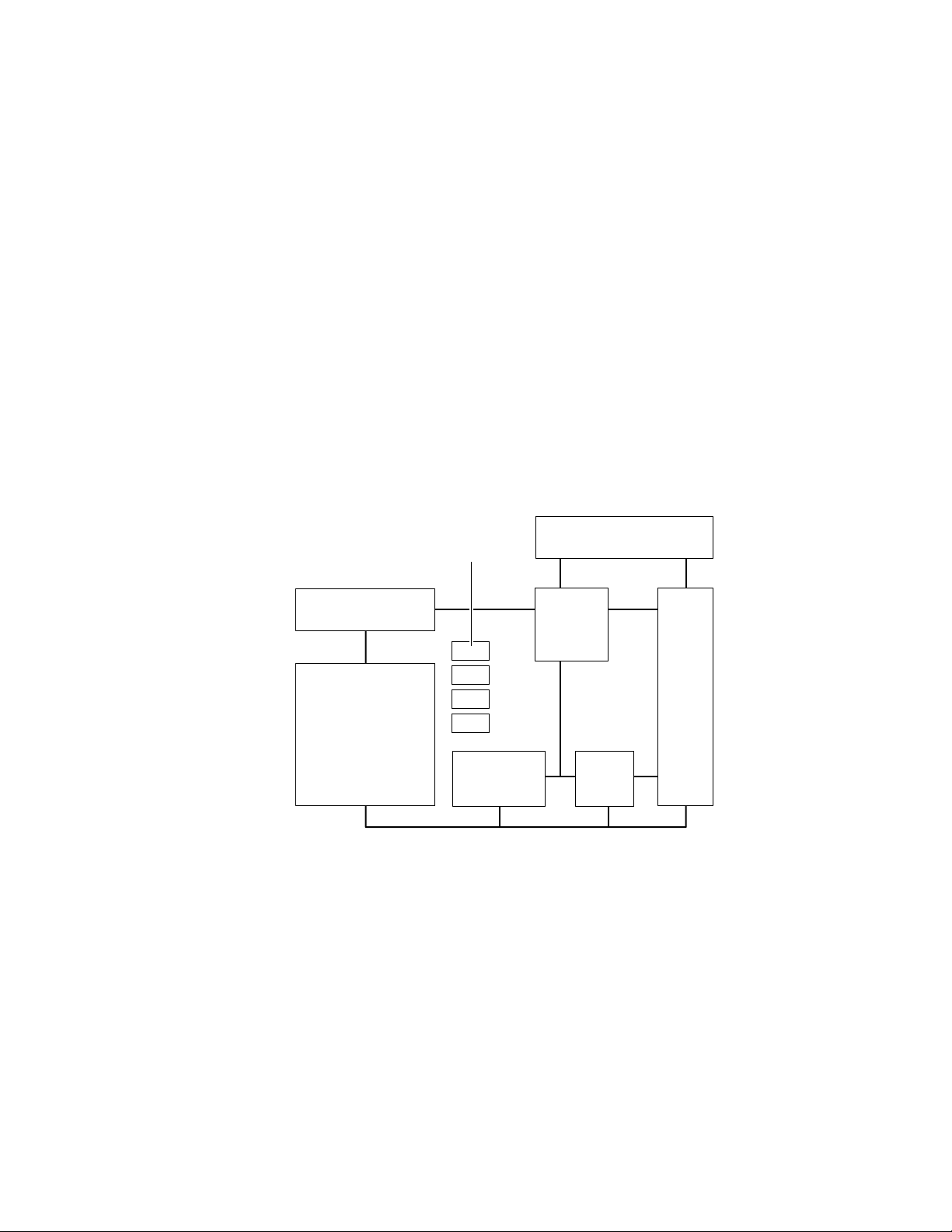
Theory of Operation
5
Functional block diagram
The printer is made of eight major blocks:
■
Imaging unit
Laser scanner
■
■
Toner cartridges
Engine boards
■
■
Fuser
Power supply
■
■
Mechanicals
Image processor board
■
Toner
cartridges
Laser scanner
Imaging
unit
Figure 5-1 Block diagram of the printer
Image processor
board
Engine
control
boards
Power
supply
FuserMechanicals
9013-10
5-2
The imaging unit
The imaging unit forms the heart of the printer. This customer-replaceable unit
contains the photoconductive belt and accumulator belt on which imaging takes
place.
The laser scanner
The laser scanner is the device that “writes“ the image onto the imaging unit’s
photoconductive belt.
Phaser 540 Color Printer
Page 85

Theory of Operation
The toner cartridges
Four toner cartridges, black, yellow, cyan and magenta, contain the primary
color toners that are sequentially transferred onto imaging unit’s
photoconductive belt depending on where the laser exposed the belt.
Subsequently, the toner is transferred to the imaging unit’s accumulator belt
from which it is transferred to a sheet of media.
The fuser
The fuser permanently bonds the toners to the media through a combination of
heat and pressure.
The engine boards
Working as the “brains” of the print engine, the engine control board coordinates
all printer functions. It contains the microprocessor and ROM that control
printer operations. The engine driver board drives the printer’s motors and
solenoids.
5
The power supply
The power supply provides regulated DC power source for the printer’s
electronics, motors and high-voltage chargers and bias rollers.
The mechanicals
Mechanicals include the motors and solenoids that drive the belts and rollers of
the printer.
The image processor board
The image processor board converts the image data from the host computer into
a raster format for the print engine.
Service Manual
5-3
Page 86

Theory of Operation
5
Laser imaging
Overview
The laser printer prints an image on paper using a technique called laser
electrophotography
Discharge Area Development or “write black.” In this process, a digitally
modulated laser, scans laterally across a negatively charged, rotating
photoconductive belt. Where the belt is exposed by the laser beam is where the
image is written and toner is transferred.
In the color print process, the photoconductive belt rotates past the laser scanner
and the toner cartridges four times, once for each primary color and black.
During each sucessive pass, the laser exposes the portions of belt that
correspond to the primary color’s component of the image. Toner is attracted to
the laser-exposed portions of the belt. As the photoconductive belt rotates it
passes the accumulator belt. As the name implies, the accumulator belt
accumulates or picks up each primary layer of toner from the photoconductive
belt and holds it, layer upon layer, until it contains the entire image. At this
point, a sheet of paper is advanced past the accumulator belt and the toner is
transferred to the sheet of paper. The paper advances to the fuser where heat
and pressure permanently bond the toner to the paper. From the fuser, the
paper is driven to the output tray.
. The printer uses the electrographic process known as
A photoconductive belt cleaning blade scrapes residual toner off of the belt
before the next primary color’s toner is applied to the belt. This prevents each
toner from contaminating the next color’s layer. The cleaning blade is in
constant contact with the belt. An accumulator belt cleaner scapes residual
toner off of the accumulator belt. This prevent an image from one print
contaminating or ”ghosting” on the next print. The blade only comes in contact
with the belt once the accumulated toner layers are transferred to the sheet of
paper.
5-4
Phaser 540 Color Printer
Page 87
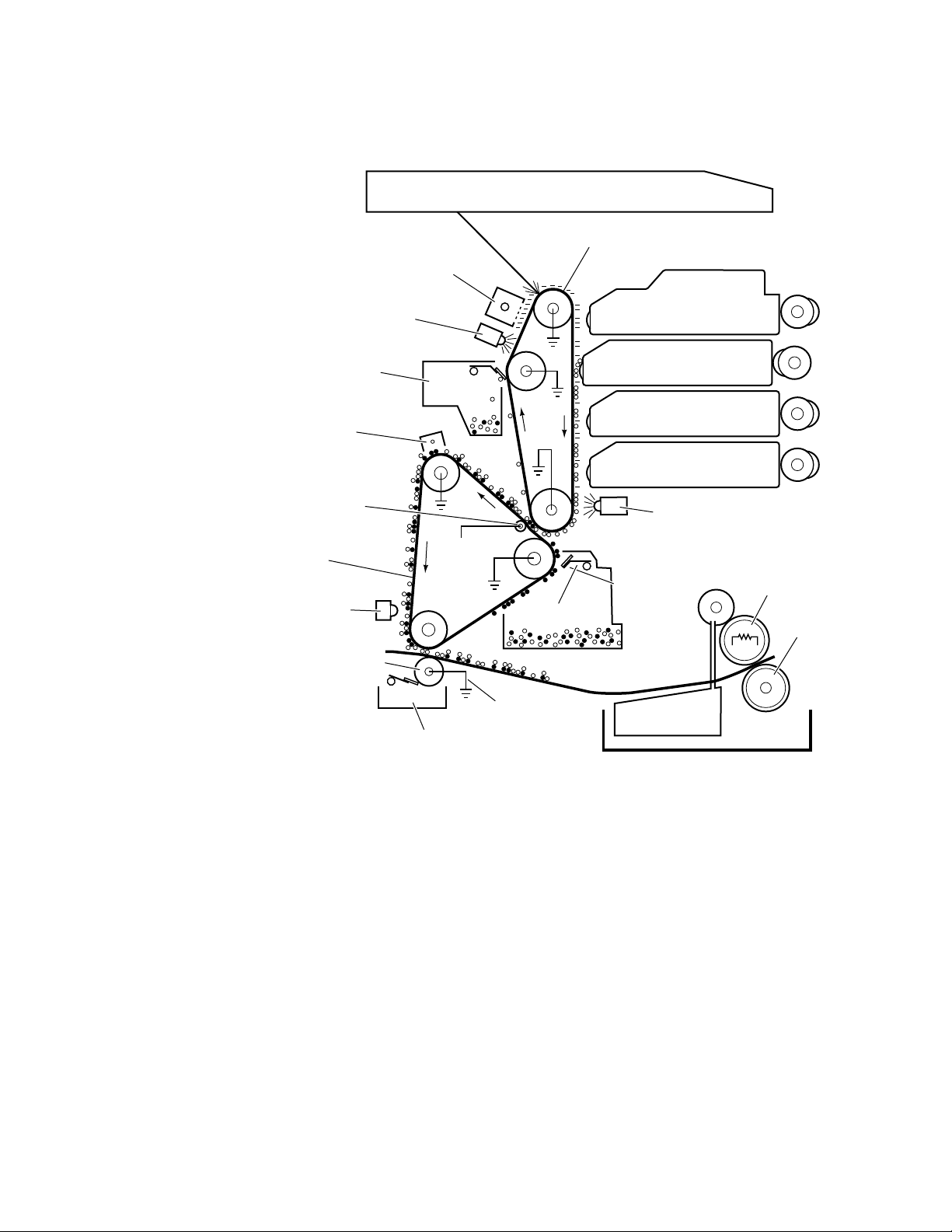
Erase
lamp
Photo conductive
belt cleaner
Pre-transfer
charger
First bias
transfer
roller
Scorotron
charger
Laser scanner
Photoconductive belt
Theory of Operation
Toner
developers
Black
Yellow
Magenta
Cyan
Pre-transfer Lamp
5
Accumulator
belt
Toner
density
sensor
Second bias
transfer
roller
+350v
On-Off
+900v - paper
+1500v - film
Bias roller
cleaner
Figure 5-2 Laser printing process overview
Accumulator
belt cleaner
Oil
Heated
roller
Pressure
roller
Fuser
9013-11
Service Manual
5-5
Page 88
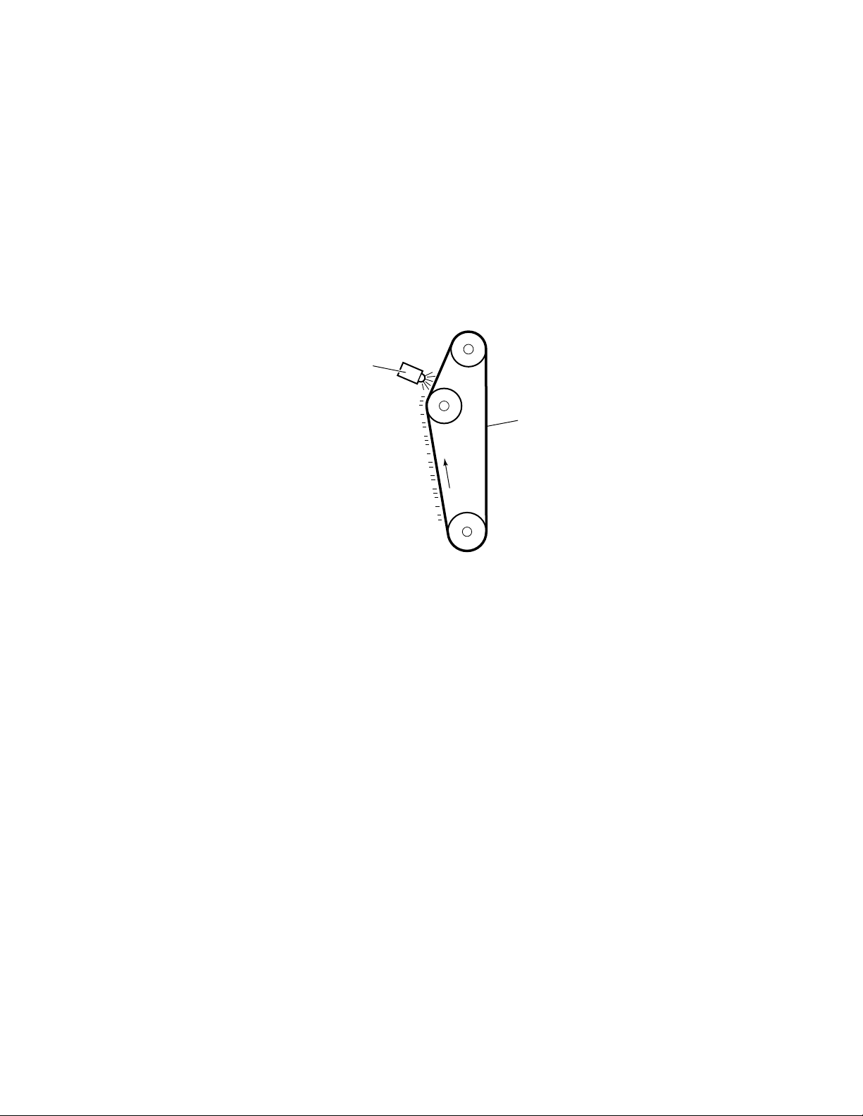
Theory of Operation
5
Pre-exposure
The print process begins when the photoconductive belt passes by the
pre-exposure lamp. The belt is moving at a speed of 96 mm-per-second for
300 dpi printing or 48 mm-per-second for 600 dpi printing. The light of the
pre-exposure lamp, which is a horizontal row of red LEDs, removes random
negative charges from the photoconductive belt. Before pre-exposure, the
surface of the belt varies from -500 volts to +50 volts. Following pre-exposure,
the voltage level of the illuminated portion of the belt only varies from 0 to +50
volts. The pre-exposure lamp is sometimes called the erase lamp since it
“erases” negative charges from the belt.
Pre-exposure
lamp
Light from the
pre-exposure
lamp LEDs
removes negative
charges from
the belt.
Figure 5-3 Pre-exposing the photoconductive belt
Photoconductive
belt
9013-13
5-6
Phaser 540 Color Printer
Page 89
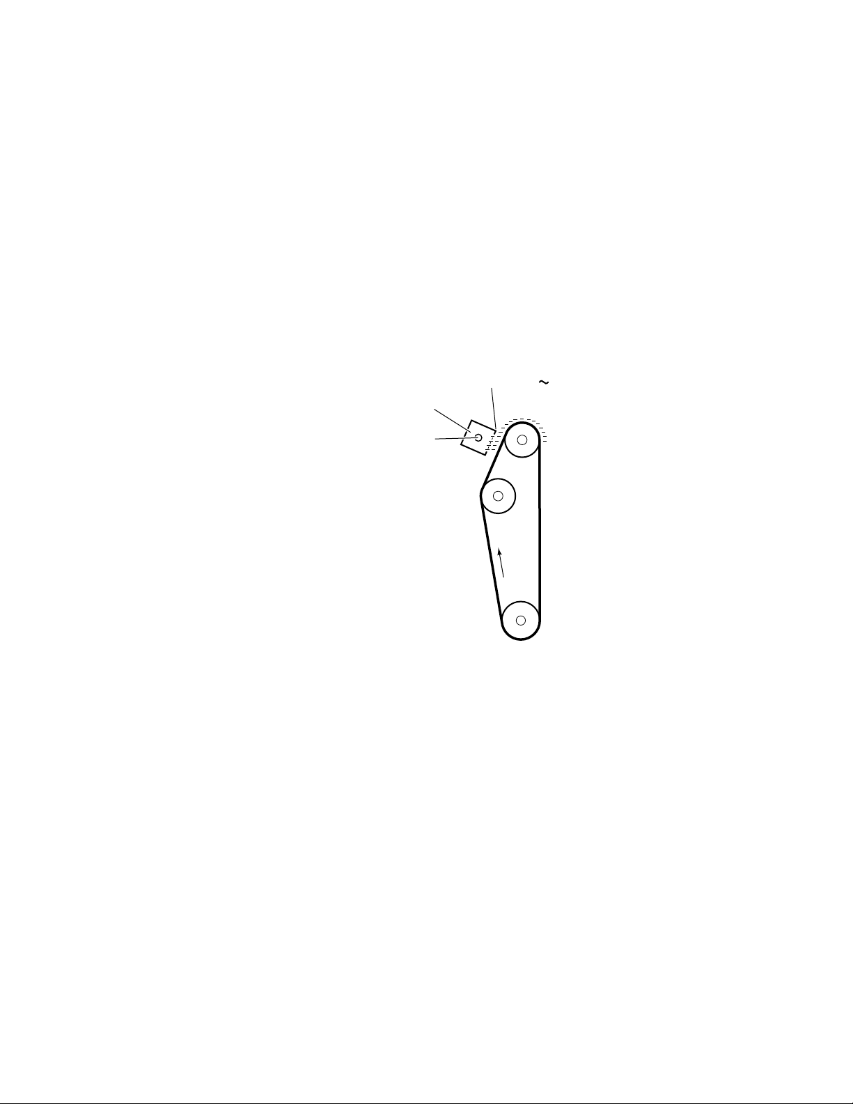
Electrostatic charging
The electrostatic potential of the belt is not uniform following pre-exposure. As
the belt rotates, it passes a scorotron charger which bombards the belt with
negative charges. The scorotron charger behaves somewhat like a vacuum tube.
The grid of the charger, held at a potential of between -500 volts (for 600dpi
printing) to -520 volts (for 300 dpi printing) and coupled with the varying
voltage potential on any discrete point on the belt’s surface, determine how
many electrons can flow from the corona wire onto that point of the belt’s
surface. The corona wire is charged to -6 kvolts with a constant current of
µ
400
varying charge of the belt surface, results in a uniform negative potential on the
belt surface of -500 volts or -520 volts, depending on the selected dot-per-inch
printing.
Theory of Operation
A. The varying electron output from the scorotron, directly based on the
Scorotron
charger
-6kv
Grid -500 -520v
5
The scorotron
charger lays down
a uniform negative
charge on the belt
surface.
9013-14
Figure 5-4 Electrostatic charging of the photoconductive belt
Service Manual
5-7
Page 90

Theory of Operation
5
Laser exposure
As the photoconductive belt rotates, the uniformly charged portion of the belt is
exposed by the modulated laser beam. As the belt passes vertically in front of
the horizontally scanning laser beam, negative charges on the belt surface are
neutralized where exposed by the beam. This forms a latent image on the belt.
The laser beam is turned off for “non-written” portions of the image.
The power of the laser beam is varied from 0.5 mW to 0.7 mW depending on
whether the printer is printing in 600 dots per inch (dpi) mode or 300 dpi mode.
Additionally, the duty cycle of the beam, for each dot, is varied from 70% to 0 to
achieve grayscale printing. Following laser exposure, the negative potential of
the belt varies in steps from -500 or -520 volts (unexposed) to -50 volts (fully
exposed).
Laser scanner
The laser beam
selectively neutralizes
some of the negative
charges on the belt
surface.
Figure 5-5 Laser exposure of the photoconductive belt
9013-15
5-8
Phaser 540 Color Printer
Page 91

The laser scanner
Lenses and mirrors in the laser scanner direct the beam at the photoconductive
belt. The beam originates at a laser diode. The beam is made parallel by the
collimator lens and is directed at the rotating polygonal mirror. The mirror
rotates at a constant 11,500 revolutions per minute. This transforms the beam
into a horizontally scanning beam, which is directed through a fwhich alters the beam’s angular rotation motion into a constant horizontal
motion. The beam then passes through a toric correction lens, which corrects the
beam for any vertical misregistration. The beam then reflects off of a mirror and
passes through a window where it scans across the rotating photoconductive
belt. At the beginning of each of its horizontal sweeps, the horizontal sync
mirror deflects the laser beam to the horizontal sync sensor. This alerts the
engine control board that the laser beam is beginning its horizontal sweep and
that it can begin to modulate the signal for the data to be printed on that line of
the image.
Laser diode
Collimator lens
Theory of Operation
Θ
primary lens,
5
Horizontal
sync mirror
Photo-conductive
belt
Rotating
mirror
f-0 primary
lens
Toric
correction
lens
Horizontal
sync sensor
Mirror
Window
Figure 5-6 The laser scanner
Service Manual
9013-16
5-9
Page 92

Theory of Operation
5
Toner pickup (development)
As the photoconductive belt continues to rotate, it passes by one of the four
toner cartridges. Each cartridge is selectively cam-driven forward to bring its
developer roller into direct contact with the belt when it is that cartridge’s turn
to transfer its toner to the belt during the belt’s four rotations past the cartridges.
The currently activated toner cartridge’s developer roller is charged to a
potential between -80 to -350 volts. Toner is attracted to the exposed portions of
the belt in reverse proportion to the amount of negative charges left on the belt.
Since the charge on the fully exposed portions of the belt is at least near -50 volts,
the greatest amount of toner is transferred. Where the negative charges are
greater at the lightly exposed or unexposed areas, less or no toner is transferred.
The developer roller rotates at 1.6 (300 dpi printing) or 2.13 (600 dpi printing)
times the speed of the photoconductive belt to ensure a constant supply of toner.
As the belt advances, it passes the pre-transfer lamp which, like the
pre-exposure lamp, removes remaining negative charges from the unexposed
portions of the belt.
Developer roller
Photoconductive
belt
Figure 5-7 Toner pickup
-120~ -350v
Toner cartridges
Pre-transfer
lamp
Black
Yellow
Magenta
Cyan
Cam driver
Toner is transferred
to the portion of the
belt exposed by the
laser beam.
The pre-transfer
lamp removes
remaining negative
charges from the
unexposed portions
of the belt.
9013-17
5-10
Phaser 540 Color Printer
Page 93

Toner transfer to the accumulator belt
As the photoconductive belt rotates, it comes in contact with the accumulator
belt, which rotates at the same speed. The first bias transfer roller, located under
the accumulator belt at the contact point with the photoconductive belt, carries a
charge of +500 volts. This strong potential attracts and holds the toner from the
photoconductive belt to the accumulator belt. The accumulator belt rotates four
times so it can pick up or accumulate each of the four toner layers, one layer on
top of the last. An accumulator belt home-position sensor sync signal, generated
from a timing mark on the accumulator belt, informs the engine control board
that it is time to begin exposing the next toner layer’s information onto the
photoconductive belt. When that happens, the accumulator belt is rotated in the
proper position to transfer the toner layer in proper registration with the
previous layer(s).
As the accumulator belt rotates, it passes the pre-transfer charger. The charger
floods the toner and belt with a uniform layer of electrons to give the toner a
strong negative charge; this will improve transfer of the toner to the paper. Any
toner remaining on the photoconductive belt after the transfer to the
accumulator belt is scraped off by the photoconductive belt cleaning blade,
which is always in contact with the belt. This leaves the photoconductive belt
clean for the next layer of toner to be transferred from the toner cartridges.
Theory of Operation
5
Photoconductive belt
cleaning blade
-5.5kv
Pre-transfer
charger
The pre-transfer
charger gives the
toner a uniform
negative charge
Accumulator
belt home
sensor
First bias
transfer
roller
+350v
Accumulator
belt
Figure 5-8 Toner transfer to the accumulator belt
Photoconductive
belt
The toner on the
photo-conductive
belt is attracted to
the strong positive
potential of the first
bias transfer roller.
Four layers of toner,
latent images of
cyan, magenta,
yellow and black,
build up on the
accumulator belt
9013-18
Service Manual
5-11
Page 94

Theory of Operation
5
Paper picking
A sheet of paper (or transparency film) is picked when a pair of cam-shaped
rollers, driven by the paper-feed motor, rotate and force a sheet of paper from
the stack into a pair of intermediate rollers. The intermediate rollers advance the
sheet of paper to the aligning rollers. The paper is pushed against the aligning
rollers slightly without them rotating to create a slight buckle in the paper,
which aligns the sheet of paper parallel to the paper path. At this point, the
paper remains stationary until the image is ready to be printed on the paper.
The pick sensor detects whether the sheet of paper arrived at the aligning rollers.
Aligning
roller
Path for
manually
fed paper
Intermediate
rollers
Figure 5-9 Paper picking
Pick
sensor
Pick rollers
Path for paper from
optional Lower Tray Assembly
9013-12
5-12
Phaser 540 Color Printer
Page 95

Toner transfer to paper
Once all four layers of toner have been picked up on the accumulator belt, a
sheet of paper (which has already been picked) is advanced to the second bias
transfer roller. (In the user manual the second bias transfer roller is referred to as
the transfer roller , a customer-replaceable consumable.) The movement of the
sheet of paper is timed so that the leading edge of the toner image on the
accumulator belt meets with the paper after 5 mm of the leading edge of the
paper has passed. A strong positive voltage (+900 volts for plain paper,
+1500 volts for transparency film for 300 dpi printing and +1000 for 600 dpi
printing on paper) in the second bias transfer roller, located under the sheet of
paper, attracts the toner from the accumulator belt to the paper. The paper (or
transparency film) advances at the same speed as the accumulator belt.
As the toner is being transferred to the paper, the accumulator belt cleaning
blade is activated. This blade scrapes any remaining traces of toner from the
accumulator belt prior to the next image transfer of toner.
Theory of Operation
5
The strong positive
potential of the
second bias transfer
roller attracts toner
to the paper.
Second bias
transfer roller
Figure 5-10 Transferring toner to the paper
The cleaning blade
scrapes leftover
traces of toner from
the accumulator belt.
Accumulator belt
cleaning blade
9013-19
Service Manual
5-13
Page 96
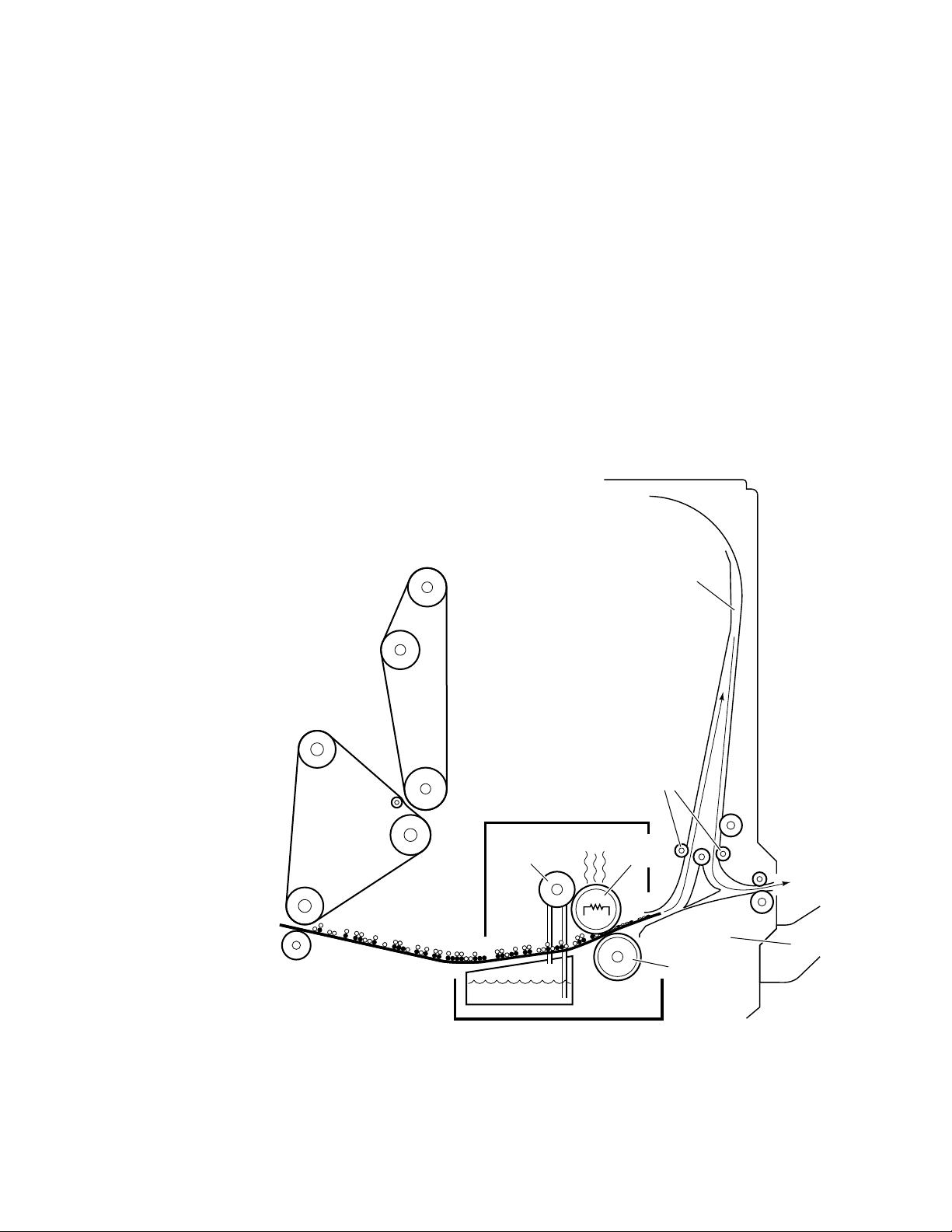
Theory of Operation
5
Fusing and exiting
As the paper receives the toner it passes through the fuser. A heated roller on
the top surface of the paper melts the toner on the paper. Sandwiched between a
pressure roller underneath and the heated roller on top, the melted toner bonds
into the paper. An oil supply keeps the heated roller lubricated so that the
melted toner does not adhere to the roller. Following fusing, the paper advances
to the output tray. When not printing, the heated roller is held at a temperature
of 160
printing, and 150
Depending on printer driver instructions, the paper may go directly to the
output tray, printed side up. Or, if instructed, the sheet of paper may be routed
to the reverser, which drives the sheet up a narrow channel and then reverses
direction, and routes the sheet of paper to the output tray upside down. This is
appropriate for a collated series of prints that need to remain in first-to-last
order.
o
C. The heater roller is set to 170
o
C for 600 dpi printing.
o
C for 300 dpi and transparency film
The reverser allows
the prints to exit to
the exit tray printed
side down
Using heat and
pressure, the fuser
bonds the toner to
the paper
Fuser unit
Oil
roller
Oil
Reverser
Reverser
rollers
Heated
roller
Output
tray
Pressure
roller
5-14
9013-20
Figure 5-11 Fusing the toner to the paper
Phaser 540 Color Printer
Page 97
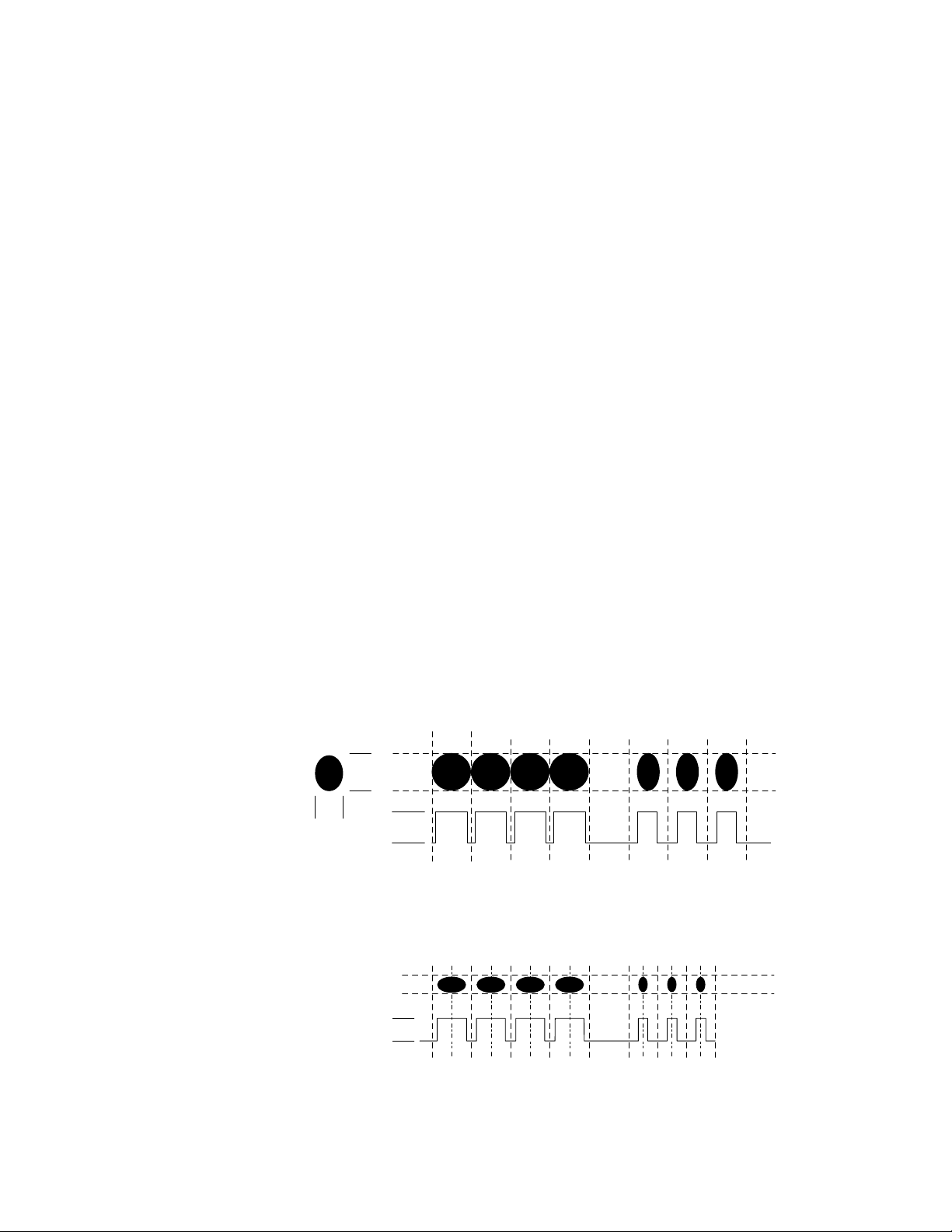
Print modes
Theory of Operation
There are three print modes: Fast, Standard and Enhanced. Standard mode is
600 dpi, bi-level printing. Enhanced mode is 600 dpi, continuous-tone printing.
Fast mode is 300 dpi, continuous-tone printing.
If no motion were involved, the laser dot produced would be an ovoid shape,
measuring about 60 microns wide by 80 microns tall. In practice, to print a dot,
the sweeping laser beam is left on long enough to create a roughly circular dot.
In Standard 300 dpi printing mode, the area allowed for a pixel is 84 microns
square. Toner particles attracted to the laser dot measure about 8 microns in
size. Allowing for vertical stacking, a solid, 300 dpi pixel may consist of only 200
to 300 toner particles. For grayscale printing, even fewer particles would be
deposited onto a pixel. As illustrated below, for printing 300 dpi solid dots the
laser beam is pulsed at a 70% duty cycle at an amplitude of 0.7 mW. (A 70% duty
cycle is used to create horizontal lines of equal thickness and scalloped
appearance as vertical lines.) To achieve grayscaling of black and color, the
beam’s duty cycle is sequentially stepped down to 0% to achieve 16 grayscale
levels at 300 dpi.
5
Standard mode 600 dpi printing is achieved by cutting in half the speed of the
photoconductive and accumulator belts and the paper transport. In addition,
the laser energy is lowered to 0.5 mW and the laser pulse rate is doubled; this
results in a slightly smaller dot.
For Enhanced mode, the laser beam duty cycle varies from 70 to 0% to create
four grayscale color levels. A technique called 2-dot modulation, where one pair
of laser pulses are combined, is used to create larger 600 dpi dots. Text and solid
colors are written at a 600 vertical lines per inch rate, while grayscaled
information is written at 300 vertical lines per inch.
84µ
60-80µ
60µ
84µ
0.7mW
70% duty
cycle of
laser beam
produces fully
saturated
dots
300 dpi
printing
Lower duty
cycle results
in lighter
saturation
of dots
0.5mW
2 dot modulation
Figure 5-12 Print modes and printing dots
Service Manual
600 dpi
printing
9013-21
5-15
Page 98

Theory of Operation
5
Automatic color correction
The printer features a unique ability to measure how much toner it is depositing
on the accumulator belt for a specific density of color. During this
self-calibration sequence, the printer exposes a portion of the photoconductive
belt with predetermined, stepped values of energy to produce a saturation
dither pattern for each color. In each case, a certain, expected amount of toner
should be transferred to the accumulator belt for each step. Reflective sensors,
located adjacent the accumulator belt, optically sense how much toner was
actually transferred to the accumulator belt; this is called the printer’s
densimetric response. This response data is transmitted to the image processor
board, which makes calculations and then downloads a color correction table to
the print engine control board. The color correction table indicates the exact
laser beam pulse duty cycle to produce properly saturated grayscales.
5-16
Phaser 540 Color Printer
Page 99
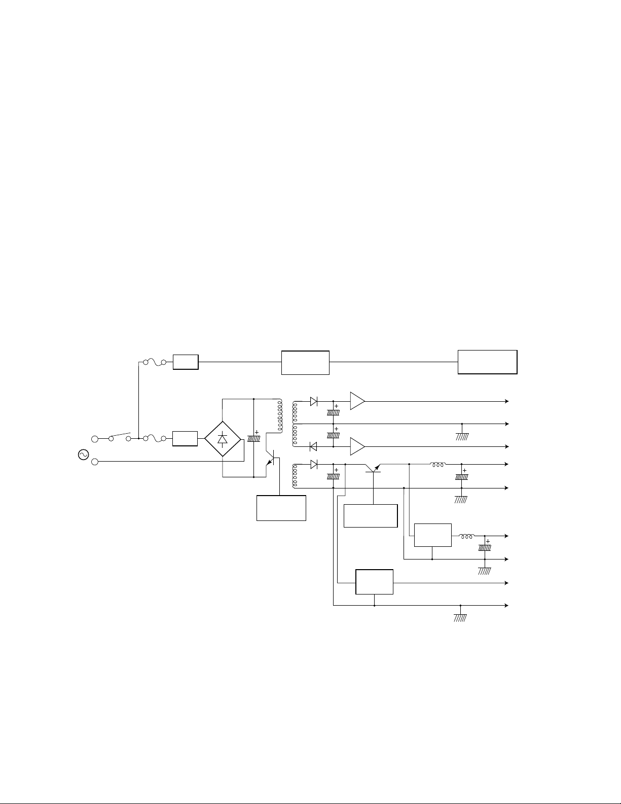
Power supply
Theory of Operation
The low voltage power supply generates five DC voltages:
■
+5 VDC for the image processor logic. For short protection., a
switching FET in the DC/DC converter monitors the output voltage
and in the event of a short, cuts the voltage off.
+5VDC for the engine control logic. For short protection, the voltage
■
difference of the choke coil and feedback to the DC/DC converter is
monitored and protected by the DC/DC converter.
■
+24 VDC for the motors, high voltage board and the cams, clutches
and solenoids. Short protection is provided by detecting the source
current of the main switching FET in the primary side and cutting off
the FET by IC control.
■
±
12 VDC for the image processor, laser diode sensor and op-amps.
Short protection is provided by a regulator IC which reduces the
output current.
5
Filter
AC
Filter
Figure 5-13 The power supply
Control IC
Zero cross
switch
Regulator IC
Regulator IC
Energy star
mode control
DC-DC
converter
DC-DC
converter
Fuser halogen
lamp (750W)
+12V
±12VGND
-12V
+24VC
+24VGND
+5VB
(engine logic)
+5VBGND
+5VC
(IP logic)
+5VCGND
9013-22
Service Manual
5-17
Page 100

5
Theory of Operation
Image processor
Image rendering technology
The image processor board handles PostScript data sent from a host computer
and transforms it into a format suitable for the print engine. The
hardware/software structure that performs this function is called a graphics
pipeline. The graphics pipeline is composed of five basic parts.
■ The I/O serializer handles the communication and protocol with the
parallel and SCSI port as well as communication with the installed
network card. The particular installed network card handles Ethernet,
LocalTalk or serial communication protocols.
■ The PostScript data received through the I/O serializer is routed to the
PostScript interpreter. The PostScript interpreter generates display lists
which describe objects and text fonts as they are to appear on the
printed page. As needed, the PostScript interpreter reads font data
stored in ROMs on the image processor board. The PostScript
interpreter also handles errors it encounters in the PostScript data.
■ The PostScript interpreter's display list is, in turn, routed to the
rasterizer. The rasterizer converts the objects and fonts into a
bitmapped image composed of color planes. Color planes are bitmaps
of the primary colors cyan, magenta and yellow that make up the
image.
■ The engine driver outputs the color bitmaps to the print engine. It
handles the data transfer buffering and basic input/output functions.
■ The control loop, which oversees the operation of the graphics pipeline,
routes the color planes to the engine driver that transmits the color
plane data to the print engine. The control loop also monitors the
control and error signals fed back from the print engine.
5-18
Phaser 540 Color Printer
 Loading...