

Page 1

Service Manual
Phaser
™
340
Color Printer
Warning
The following servicing instructions are for
use by qualified service personnel only. To
avoid personal injury, do not perform any
servicing other than that contained in
operating instructions unless you are qualified
to do so.
This printing Febuary 1996
070-9100-01
Page 2

Copyright
©
1996 by Tektronix, Inc., Wilsonville, Oregon. Printed in the United States of America. All rights
reserved. Contents of this publication may not be reproduced in any form without permission of Tektronix, Inc.
This instrument, in whole or in part, may be protected by one or more U.S. or foreign patents or patent applications.
Information provided upon request from Tektronix, Inc., P.O. Box 1000, Wilsonville, Oregon 97070-1000.
If acquired subject to FAR or DFARS, the following shall apply:
■
Unpublished — rights reserved under the copyright laws of the United States.
■
Restricted Rights Legend — Use, duplication or disclosures by the government is subject to restrictions as set forth
in subparagraph (c) (1) (ii) of the Rights in Technical Data and Computer Software at DFARS 252.227-7013, or in
subparagraph (c) (2) of the Commercial Computer Software – Restricted Rights clause at FAR 52.227-19, as
applicable. Tektronix, Inc., P.O. Box 1000, Wilsonville, Oregon 97070-1000.
Tektronix
®
is a registered trademark of Tektronix, Inc. TekColor™ and Photofine™ are trademarks of Tektronix, Inc.
Phaser™ is a trademark of Tektronix, Inc. for color printers and related products.
Adobe™ and PostScript™ are trademarks of Adobe Systems, Incorporated which may be registered in certain
jurisdictions.
PowerBook®, Macintosh® and EtherTalk® is a registered trademark of Apple Computer, Incorporated.
Times™, Helvetica™, and Palatino™ are trademarks of Linotype-Hell AG and/or its subsidiaries.
Micronta® is a registered trademark of Radio Shack.
Microsoft® and Microsoft Windows® are registered trademarks of Microsoft Corporation.
Novell® and NetWare® are registered trademarks of Novell, Inc.
OS/2® is a registered trademark of International Business Machine Corporation.
PANTONE
®
* Colors generated by the Phaser 340 Color Printer are four-color process simulations and may not
match PANTONE-identified solid color standards. Use current PANTONE Color Reference Manuals for accurate
colors.
PANTONE Color simulations are only obtainable on these products when driven by qualified Pantone-licensed
software packages. Contact Pantone, Inc. for a current list of qualified licensees.
* Pantone, Inc.’s check-standard trademark for color reproduction and color reproduction materials.
© Pantone. Inc., 1988.
TCP/IP is a trademark of FTP Software. Copyright (c) 1986, 1987, 1988, 1989 by FTP Software, Inc. All rights
reserved. PC/TCP for DOS is based on a set of programs originally designed and developed by the Massachusetts
Institute of Technology. FTP Software has made extensive modifications and enhancements to the M.I.T. programs.
TokenTalk® is a registered trademark of Apple Computer, Incorporated.
TORX™ is a trademark of TEKTRON.
The X Window System™ is a trademark of Massachusetts Institute of Technology.
Other marks are trademarks or registered trademarks of the companies with which they are associated.
TE/JG/CC
Page 3

Users safety summary
Terms in manual:
Power source:
conductor and ground. Use only the specified power cord and connector. Refer to a qualified service technician for
changes to the cord or connector.
Operation of product:
product. Do not operate without the covers and panels properly installed. Do not operate in an atmosphere of
explosive gases.
Safety instructions:
Terms on product:
Care of product:
power cord or plug is frayed or otherwise damaged, if you spill anything into the case, if product is exposed to any
excess moisture, if product is dropped or damaged, if you suspect that the product needs servicing or repair, and
whenever you clean the product.
CAUTION Conditions that can result in damage to the product.
WARNING Conditions that can result in personal injury or loss of life.
Do not apply more than 250 volts RMS between the supply conductors or between either supply
Avoid electric shock by contacting a qualified service technician to replace fuses inside the
WARNING Turning the power off using the On/Off switch does not de-energize the printer.
You must remove the power cord to disconnect the printer from the mains. Keep
the power cord accessible for removal in case of an emergency.
Read all installation instructions carefully before you plug the product into a power source.
CAUTION A personal injury hazard exists that may not be apparent. For example, a panel
may cover the hazardous area. Also applies to a hazard to property including the
product itself.
DANGER A personal injury hazard exists in the area where you see the sign.
Disconnect the power plug by pulling the plug, not the cord. Disconnect the power plug if the
Ground the product:
necessary, contact a licensed electrician to install a properly grounded outlet.
Symbols as marked on product:
DANGER high voltage:
Protective ground (earth) terminal:
Use caution. Refer to the manual(s) for information:
Plug the three-wire power cord (with grounding prong) into grounded AC outlets only. If
!
WARNING:
cause an electrical shock. Electrical product may be hazardous if misused.
If the product loses the ground connection, usage of knobs and controls (and other conductive parts) can
Page 4

Service safety summary
For qualified service personnel only:
Do not service alone:
rendering first aid or resuscitation is present.
Use care when servicing with power on:
personal injury, do not touch exposed connections and components while power is on.
Disconnect power before removing the power supply shield, soldering, or replacing components.
Do not wear jewelry:
contact with dangerous voltages and currents.
Power source:
between the supply conductors or between either supply conductor and ground. A protective ground connection by
way of the grounding conductor in the power cord is essential for safe operation.
Do not perform internal service or adjustment of this product unless another person capable of
Remove jewelry prior to servicing. Rings, necklaces, and other metallic objects could come into
This product is intended to operate from a power source that will not apply more than 250 volts rms
Refer also to the preceding Users Safety Summary.
Dangerous voltages may exist at several points in this product. To avoid
Page 5

Contents
1 General Information
Phaser 340 overview 1-2
Solid inks 1-3
Memory considerations 1-3
Print engine assemblies 1-4
The main board 1-12
Combination sensors and their meanings 1-13
Media tray type sensing 1-13
Rear panel 1-14
Front panel 1-15
Specifications 1-16
Regulatory specifications 1-20
2 Installing the Printer and Drivers
Pre-install questions for customers 2-2
Unpacking 2-6
Inventory for printer 2-6
Setting up the printer 2-8
Cabling the printer 2-10
Connecting the printer to a Macintosh 2-10
LocalTalk connection to a Macintosh 2-10
Ethernet connection to a Macintosh 2-10
Connecting the printer to a PC 2-11
Direct connection to a PC 2-11
Networked connection to a PC using the printer’s Ethernet port 2-11
Connecting the printer to a workstation 2-11
Direct connection to a workstation 2-11
Networked connection to a workstation 2-11
Installing a SCSI hard disk drive on a Phaser 340 2-12
Connecting the optional CopyStation to the printer 2-13
Turning on the printer 2-14
Startup page 2-14
Configuration page 2-15
Service Manual
v
Page 6

vi
Driver and communication setup 2-21
Installing a Macintosh driver 2-21
Phaser 340 driver 2-21
Phaser 340 GX driver 2-22
Installing a printer driver for Microsoft Windows 95 2-23
Installing the Tektronix driver for Windows 3.1 2-25
If you have other Tektronix printer drivers already installed 2-25
Configuring the Tektronix Windows printer driver 2-26
Updating the standard Microsoft Windows PostScript driver 2-28
Installing the printer driver for OS/2 Version 2 2-29
Configuring the printer's serial port for a PC 2-31
Using printcap to configure a Unix workstation for the printer's serial port 2-31
Configuring a Novell NetWare server for the printer 2-32
Configuring TCP/IP 2-33
3 Verifying the Printer and Host Connections
Verifying printing from a Macintosh 3-1
Selecting the printer via the Chooser 3-1
Printing the directory from a Macintosh 3-2
Verifying that an application communicates to the printer 3-3
Using the Error Handler utility 3-3
Verifying printing from a PC 3-4
DOS connection verification 3-4
Windows 95 driver verification 3-4
Windows 3.1 driver verification 3-5
OS/2 connection verification 3-6
Novell NetWare verification 3-7
Send a print file to the printer 3-7
Using the Error Handler utility 3-8
Verifying printing from a workstation 3-9
Verifying and printing using the TCP/IP protocols 3-9
Using the Error Handler utility 3-10
Phaser 340 Color Printer
Page 7

4 Key Operator Training
Printer controls and indicators 4-2
Printer rear panel connections 4-2
Loading consumables 4-3
Cleaning 4-4
Clearing paper jams 4-5
Affecting print quality 4-5
Moving the printer 4-5
Warranty information 4-6
Supplies ordering 4-6
If you need help 4-6
Customer Support Hotline 4-6
Service support 4-6
Electronic Bulletin Board Service 4-7
Using the automated fax systems 4-7
Tektronix Color Printer Information Server 4-10
Accessing the printer’s web page 4-10
5 Theory of Operation
Overview 5-1
Functional block diagram 5-2
Drum/transfix assembly 5-3
Maintenance tray 5-5
Printhead 5-7
Ink loader 5-11
Cap/wipe/purge assembly 5-12
Power supply 5-14
Main board 5-16
Print process in operation 5-18
Printhead tilt 5-18
Drum preparation 5-20
Printing 5-22
Paper pick 5-26
Transfixing, stripping and exiting 5-28
Printer self-maintenance 5-30
Printhead maintenance cycle 5-30
Paper preheater cleaning 5-33
Pick roller cleaning 5-33
Transfix roller oiling 5-34
Drum cleaning (chase page) 5-34
Service Manual
vii
Page 8

6 Troubleshooting
System power-up sequence 6-1
Print engine troubleshooting 6-3
Verifying main board CPU operation 6-3
Verifying print engine operation by using its test print 6-5
Verifying power supply operation 6-5
Measuring power supply voltages 6-5
Inspecting the power supply fuses 6-8
Testing for a shorted DC supply 6-8
Testing for a shorted motor 6-9
Testing motor and solenoid resistances 6-9
Media jams and the paper path 6-10
Media-based problems 6-10
Paper-pick errors 6-10
Print transfer jams 6-11
Checking the process motor and drive train 6-11
Media skews passing through the paper path 6-12
Printing and print quality problems 6-12
Streaks or lines in the print parallel to the short axis of printing 6-12
Streaks or lines in the print parallel to the long axis of printing 6-13
Scratches in the transparency parallel to the long axis of printing 6-13
White portion of print is colored 6-13
Color is uneven 6-14
Not printing 6-14
Printing too light or too dark 6-14
Image is offset or cut off 6-14
Wrinkling 6-14
Oil streaks on top of print 6-14
Error codes and messages 6-15
viii
Phaser 340 Color Printer
Page 9

ix
PC-based diagnostics 6-27
Requirements 6-27
Starting the diagnostics 6-28
Selecting tests 6-31
Running tests 6-33
Saving and restoring test selections 6-38
Saving and restoring other settings 6-38
The diagnostic pull-down menus summary 6-39
Test Command (Alt-T) 6-39
View Menu 6-39
Run Command 6-39
Next Command 6-39
Stop Command 6-39
File Menu (Alt-F) 6-40
Options Menu 6-40
Help Menu 6-40
Problems and solutions 6-41
Power problems 6-41
Front panel indications 6-41
Macintosh printing problems 6-41
PC DOS printing problems 6-43
Windows printing problems 6-44
Workstation printing problems 6-45
Image processor hard and soft error indicators 6-45
7 Cleaning and Maintenance
Cleaning 7-2
Cleaning Page 7-3
Vacuum 7-3
Drum temperature sensor 7-3
Maintenance 7-4
Maintenance tray 7-4
Waste tray 7-4
Lubrication 7-5
Inspection 7-6
Service Manual
Page 10

x
8 Field Replaceable Unit Disassembly/Assembly
Required tools 8-1
Lower Paper Tray Assembly 8-2
Cabinet panels and covers 8-4
Ink loader 8-6
Metal dust cover 8-8
Fans 8-9
Rear fan 8-9
Drum fan 8-10
Power supply 8-12
Vacuum system 8-14
Vacuum pump 8-14
Accumulator 8-15
Solenoid valve 8-16
Y-axis belt drive assembly 8-18
Heaters 8-20
Paper preheater 8-20
Drum heater 8-22
Drum position sensor assembly 8-24
Drum/transfix assembly 8-27
Motors 8-32
Y-axis (drum) motor and process motor 8-32
Cap/wipe/purge drive motor 8-34
X-axis drive assembly 8-36
Printhead 8-37
Cap/wipe/purge assembly 8-41
Upper and lower stripper finger assemblies 8-43
Rollers 8-44
Exit roller 8-44
Lower feed roller and feed roller magnetic clutch 8-46
Pick roller 8-47
Head tilt cam gear 8-49
Replacement 8-50
Phaser 340 Color Printer
Page 11

xi
Circuit boards 8-53
I/O board 1 8-53
I/O board 2 and I/O board 3 8-54
I/O board 4 8-55
Power control board 8-56
Interconnect board 8-58
Main board 8-60
RAM SIMM 8-61
Code ROM SIMM 8-62
Network card 8-63
Enabling TCP/IP with the authorization code 8-64
9 Checks and Adjustments
Required tools summary 9-1
Front panel menu 9-2
Bypass mode (Version 2 printers) 9-5
Cool down mode (Version 2 printers) 9-6
Printing test prints 9-6
Printing service test prints 9-6
Printing the configuration page 9-7
Adjustments 9-8
Paper-feed belt tension adjustment 9-8
Y-axis belts tension adjustment 9-9
Printhead-to-drum spacing adjustment 9-11
Cap/wipe/purge assembly belt adjustments 9-13
Drum position encoder gap 9-15
Vacuum check 9-17
Adjusting for best print quality 9-19
Resetting NVRAM 9-21
Viewing NVRAM contents 9-22
A Field Replaceable Units List
B Test Patterns
C Wiring Diagrams
Index
Service Manual
Page 12

Figures
Figure 1-1
Figure 1-2
Figure 1-3
Figure 1-4
Figure 1-5
Figure 1-6
Figure 1-7
Figure 1-8
Figure 1-9
Figure 1-10
Figure 1-11
Figure 1-12
Figure 2-1
Figure 2-2
Figure 2-3
Figure 2-4
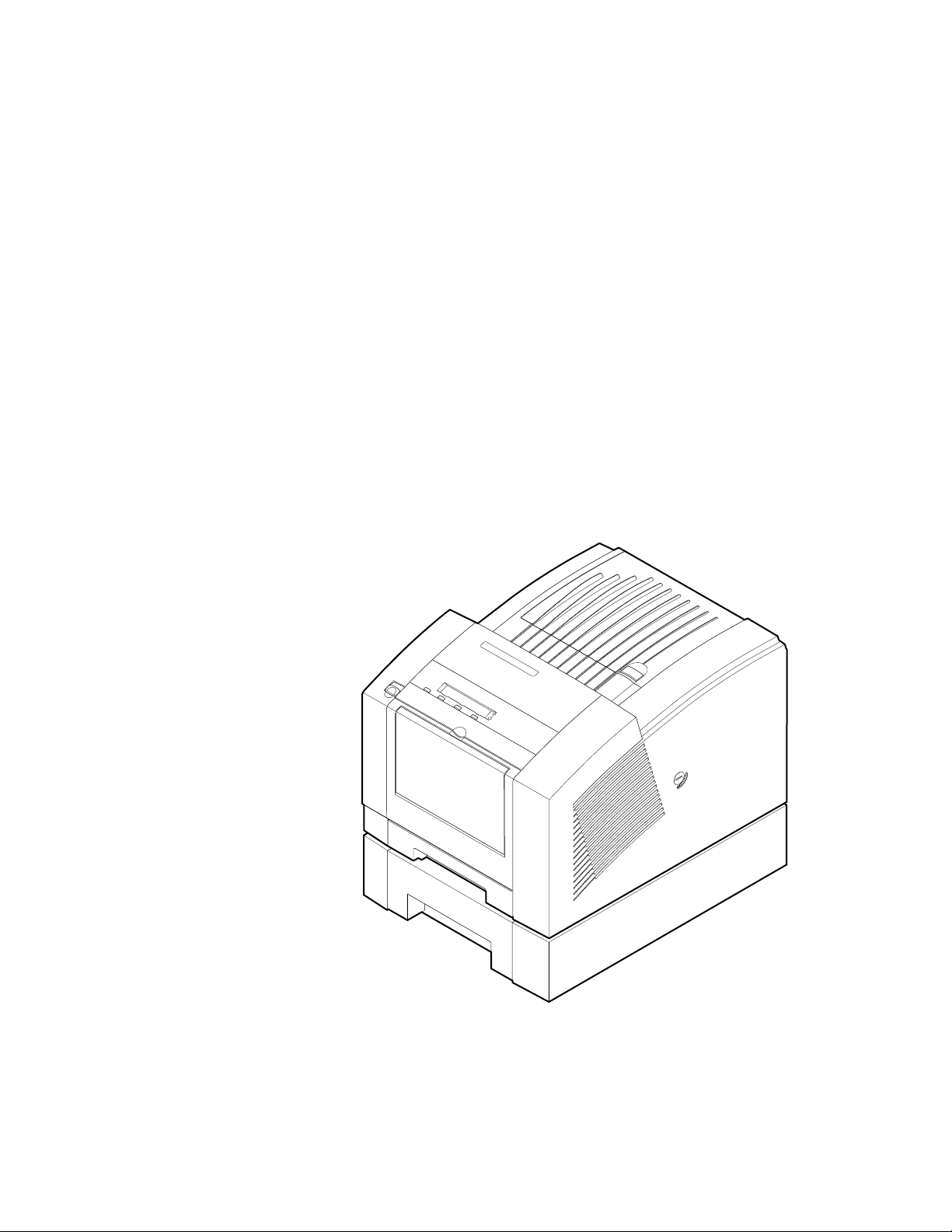
The Phaser 340 printer (shown with optional Lower Paper Tray Assembly) 1-1
Internal features of the print engine 1-4
Circuit boards of the print engine (right front view) 1-5
Circuit boards of the print engine (left-rear view) 1-6
The printer’s I
Printhead maintenance system of the print engine 1-8
Left-side sensors and switches on the print engine 1-9
Right-side sensors and switches on the print engine 1-10
Solenoids on the print engine 1-11
Features of the main board 1-12
Printer rear panel with the optional Ethernet card 1-14
Printer front panel 1-15
The printer packaging 2-7
Unlocking the transit restraint lock 2-8
Connecting a SCSI hard disk drive to a Phaser 340 2-12
Connecting a CopyStation to a Phaser 340 2-13
2
C bus 1-7
Figure 5-1
Figure 5-2
Figure 5-3
Figure 5-4
Figure 5-5
Figure 5-6
Figure 5-7
Figure 5-8
Figure 5-9
Figure 5-10
Figure 5-11
Figure 5-12
Figure 5-13
Figure 5-14
Figure 5-15
Overview of the printer 5-2
The drum and its systems 5-3
The drum/transfix assembly 5-4
The drum maintenance cartridge 5-5
The printhead 5-7
The ink-jet array nozzle arrangement and cross-section 5-8
X-axis printhead movement during printing 5-9
The printhead tilting mechanism 5-10
The ink loader 5-11
The cap /wipe/purge assembly 5-12
The cap/wipe/purge assembly and vacuum system 5-13
Power supply block diagram 5-15
Main board block diagram 5-17
Tilting the printhead 5-19
Drum preparation for printing 5-21
xii
Phaser 340 Color Printer
Page 13

Figure 5-16
Figure 5-17
Figure 5-18
Figure 5-19
Figure 5-20
Figure 6-1
Figure 6-2
Figure 6-3
Figure 6-4
Figure 6-5
Figure 6-6
Figure 6-7
Figure 6-8
Figure 6-9
Figure 6-10
Figure 6-11
Figure 6-12
Printing the latent (pre-transfer) image on the drum 5-23
Printing the latent (pre-transfer) image on the drum (later printers) 5-25
Paper picking and positioning for transfixing 5-27
Image transfixing, stripping and paper exiting 5-29
The printhead maintenance cycle 5-32
Measuring the DC voltages (test points) and fuses 6-7
Turning off AppleTalk 6-28
Configuring SoftPC’s Serial Port 6-29
PC-based diagnostics screen display 6-30
The diagnostics global help screen 6-32
The Test Suite list 6-33
The Individual test within a selected test suite 6-34
Running a test 6-35
An Individual Test help screen 6-36
Sensor Test summary 6-36
Test result of a Motor Motion test 6-37
The Thermal Test 6-37
Figure 7-1
Figure 8-1
Figure 8-2
Figure 8-3
Figure 8-4
Figure 8-5
Figure 8-6
Figure 8-7
Figure 8-8
Figure 8-9
Figure 8-10
Figure 8-11
Figure 8-12
Figure 8-13
Figure 8-14
Figure 8-15
Phaser 340 cleaning page 7-3
Removing the Lower Paper Tray Assembly 8-3
Removing the printer panels and covers 8-5
Removing the ink loader 8-7
Removing the metal dust cover 8-8
Removing the rear fan 8-9
Removing the drum fan 8-11
Removing the power supply 8-13
Removing the vacuum pump 8-14
Removing the accumulator 8-15
Removing the solenoid valve 8-17
Removing the Y-axis belt drive assembly 8-19
Removing the paper preheater 8-21
Removing the drum heater 8-23
Marking the drum-to-drum home flag sensor alignment 8-25
Removing the drum position sensor assembly 8-26
Service Manual
xiii
Page 14

Figure 8-16
Figure 8-17
Figure 8-18
Figure 8-19
Figure 8-20
Figure 8-21
Figure 8-22
Figure 8-23
Figure 8-24
Figure 8-25
Figure 8-26
Figure 8-27
Figure 8-28
Figure 8-29
Figure 8-30
Figure 8-31
Figure 8-32
Figure 8-33
Figure 8-34
Figure 8-35
Figure 8-36
Figure 8-37
Figure 8-38
Figure 8-39
Removing the drum/transfix assembly (left side) 8-28
Removing the drum/transfix assembly (right side) 8-29
Removing the drum/transfix assembly (front) 8-31
Removing the process motor or the Y-axis motor 8-33
Removing the cap/wipe/purge drive motor 8-35
Removing the X-axis drive assembly 8-36
Plugging the reservoir holes 8-38
Removing the printhead 8-39
Removing the cap/wipe/purge assembly 8-42
Removing the upper and lower stripper finger assemblies 8-43
Removing the exit roller 8-45
Removing the feed roller 8-46
Removing the pick roller 8-48
Removing the cam follower pin 8-49
Removing the head tilt cam gear for removal 8-50
Adjusting the cam follower pin 8-51
Removing I/O board 1 8-53
Removing I/O board 2 and I/O board 3 8-55
Removing the power control board 8-57
Removing the interconnect board 8-59
Removing the main board 8-60
Installing the RAM SIMM on the main board 8-61
Installing the code ROM SIMM on the main board 8-62
Installing the network card in the printer 8-63
xiv
Phaser 340 Color Printer
Page 15

Figure 9-1
Figure 9-2
Figure 9-3
Figure 9-4
Figure 9-5
Figure 9-6
Figure 9-7
Figure 9-8
Figure 9-9
Figure 9-10
Figure 9-11
Figure 9-12
Figure 9-13
Figure 9-14
Figure 9-15
Figure 9-16
Figure A-1
Figure A-2
Figure A-3
Main menu roadmap (printers serial-numbered B0xxxxx thru BBxxxxx) 9-2
Main menu roadmap (printers serial-numbered B0xxxxx thru BBxxxxx - continued) 9-3
Main menu roadmap (printers serial-numbered BCxxxxx and up) 9-4
Main menu roadmap (printers serial-numbered BCxxxxx and up - continued) 9-5
Setting paper-feed belt tension 9-8
Setting the Y-axis belt tension 9-10
Printhead to drum gap adjustment menu 9-11
Spacing the printhead to the drum 9-12
Aligning (timing) the cap/wipe/purge assembly drive belts 9-14
Setting the drum position encoder gap 9-16
Connecting the vacuum gauge to the printer 9-17
Selecting the vacuum check test 9-18
Printhead test menu 9-19
Printhead weak jet adjustment 9-20
NVRAM Test menu 9-21
Viewing NVRAM contents 9-22
The printer exterior FRUs A-3
The printer interior FRUs A-7
The printer interior FRUs (left side) A-9
Figure C-1
Figure C-2
Figure C-3
Figure C-4
Figure C-5
Figure C-6
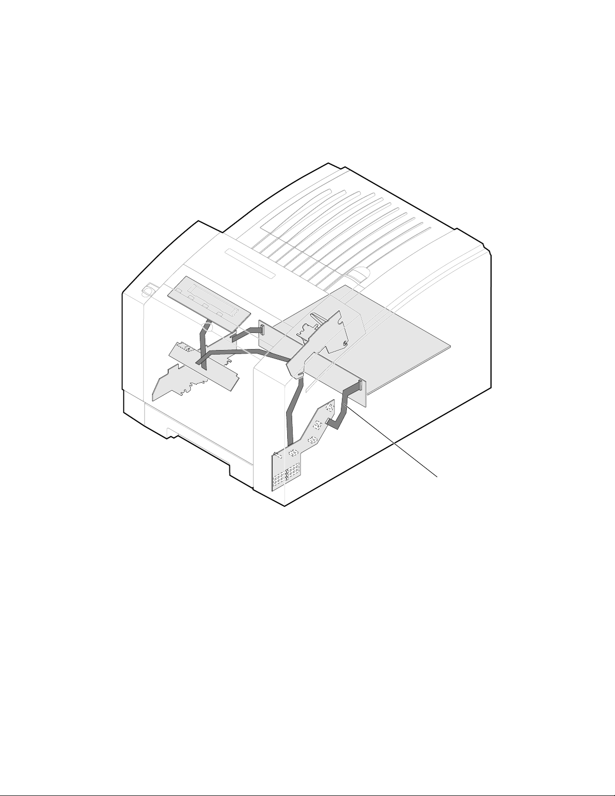
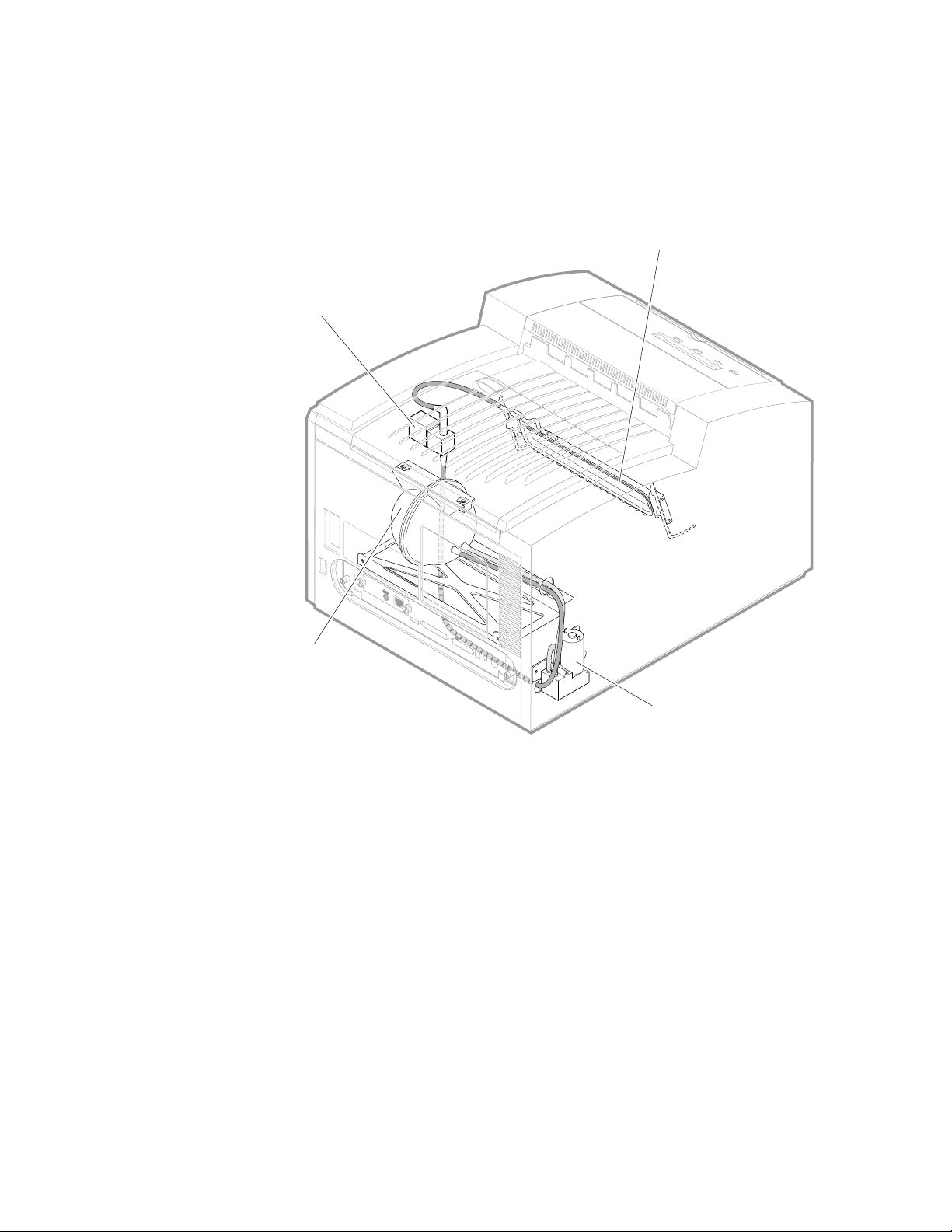
Print engine wiring diagram C-1
Wire dressing around the x-axis drive C-2
Wire dressing the vacuum hose and drum fan C-2
Wire dressing behind the printhead C-3
Routing ink loader sensor wiring harness C-3
Routing wiring on the left side of the printer C-4
Service Manual
xv
Page 16

Tables
Table 1-1
Table 1-2
Table 1-3
Table 1-4
Table 1-5
Table 1-6
Table 2-1
Table 6-1
Table 6-2
Table 6-3
Table 6-4
Table 6-5
Table 6-6
Table 6-7
Table 6-8
Table 6-9
Table 6-10
Tray switch sensor combinations 1-13
Physical dimensions 1-16
Printer clearances 1-16
Functional specifications 1-17
Electrical specifications 1-18
Environmental specifications 1-19
Configuration page settings 2-15
29K processor power up self-test error codes 6-3
68K processor power up self-test error codes 6-4
Motor and solenoid resistances 6-9
Front panel and fault history log error codes and messages 6-15
Power problems 6-41
Front panel indicators and their meanings 6-41
Macintosh printing problems 6-41
PC DOS printing problems 6-43
Windows printing problems 6-44
Workstation printing problems 6-45
xvi
Phaser 340 Color Printer
Page 17
Chapter
1
General Information
This service manual contains information useful to verify operation,
troubleshoot, repair, adjust, and maintain a Tektronix Phaser™ 340 Color Printer.
The first half of this manual familiarizes you with the printer and provides
information on installing and verifying the printer and training printer
customers as a part of the Option S0 printer installation procedure. The latter
half of the manual includes troubleshooting guides, adjustment procedures,
assembly/disassembly procedures and an FRU list.
To ensure complete understanding of the product, we recommend participation
in Phaser 340 service training, if available.
9100-01
Figure 1-1 The Phaser 340 printer (shown with optional Lower Paper Tray Assembly)
Service Manual
1-1
Page 18

General Information
1
Phaser 340 overview
The Phaser 340 Color Printer is an Adobe PostScript Level 2 color, solid ink-jet
printer with Tektronix color matching extensions (TekColor 3.0). The Phaser 340
is marketed in two variations: The Phaser 340 and the Phaser 340 Plus.
Externally and mechanically, the Phaser 340 and Phaser 340 Plus are identical.
The startup page indicates whether the printer is a “Plus” model. Additionally,
the Macintosh printer driver indicates if the printer is a “Plus” model.
Note
The Phaser 340 prints at an addressability of 300 dots per inch (dpi) and features
17 built-in fonts and 8 Mbytes of RAM, which can be upgraded to 12 Mbytes.
The Phaser 340 Plus prints at an addressability of 600 x 300 dots-per-inch or
300 x 300 dpi, features up to 69 built-in fonts, and comes with 24 Mbytes of
RAM. The Phaser 340 Plus is also capable of job pipelining; it can print one
image and process the data for the next image at the same time.
Both printers features two available paper trays: A and A4, with an optional
500-sheet high-capacity Lower Paper Tray Assembly which gives the printer a
dual-tray capability. (The Lower Paper Tray Assembly is sometimes referred to
as the second feeder; it only supports paper printing.) The printers print images
on A- and A4-size paper and transparency film with 5 mm (0.2 in.) margins; the
bottom margin is 7 mm (0.3 in). Each can print up to a rate of four pages per
minute; although the Phaser 340 Plus has greater image processing capabilities
for better image throughput. Both variations feature a SCSI port to support an
external SCSI disk for additional font storage and the Phaser CopyStation copier
option.
Unless otherwise noted, descriptions and servicing are identical for
the Phaser 340 and the Phaser 340 Plus.
Early in 1996, Tektronix introduced a significantly redesigned
Phaser 340 and Phaser 340 Plus, denoted by the serial number
xxxx and higher. These printers are often referred to as Version 2
BCx
printers. Theses printer feature some new FRU components that are
not compatible with older printers. These printers also have a updated
front panel menu structure with new menu items.
1-2
A 68K processor oversees print engine operations; the printer’s PostScript image
processor is powered by a 32-MHz 29K RISC processor. The printer features an
integral bi-directional parallel port. A rear panel slot allows customers to install
one “smart card” Phaser Share Network Card. One card provides an RS-232C
serial port and a LocalTalk port. A second, alternative card offers an Ethernet
port which includes standard support for EtherTalk and Novell NetWare.
A third card provides a Token Ring interface supporting Novel NetWare,
TokenTalk, and TCP/IP. TCP/IP protocol support is standard in printers
serial-numbered BC01
a downloaded software key in earlier printers.
Phaser 340 Color Printer
xxx and up. TCP/IP protocol is optionally supported via
Page 19

Solid inks
Solid inks, sometimes called phase-change inks, are solid at room temperature
and are liquid at the higher temperature used during printing. The inks solidify
almost instantly after being jetted onto the printer’s drum. Because Tektronix'
proprietary solid inks bleed much less than ordinary liquid inks, they allow the
printer to print brilliant colors on plain paper.
Note
Turning the printer off and allowing it to cool causes it to perform a
printhead cleaning and purge cycle upon power-up. The printer's
purge cycle consumes a significant amount of ink. During normal use
and servicing, turn the printer off and allow it to cool only when
necessary.
Memory considerations
Phaser 340.
300 x 300 dpi printing and features 1.5 Mbytes of virtual memory. With a
4 Mbyte upgrade (12 Mbytes total) the printer’s virtual memory is increased to
3 Mbytes. A 16-Mbyte RAM SIMM can be installed in the Phaser 340, but it will
only recognize 4 Mbytes of the SIMM.
With a base memory configuration of 8 Mbytes, the printer delivers
General Information
1
Phaser 340 Plus.
600 x 300 dpi, job pipeline 600-dpi images, off-load images from the host faster
than a base Phaser 340, store more downloadable fonts, improve imaging
performance, and increase the input memory buffer for the parallel port.
With its total of 24 Mbytes, the Phaser 340 Plus can print
Service Manual
1-3
Page 20
General Information
1
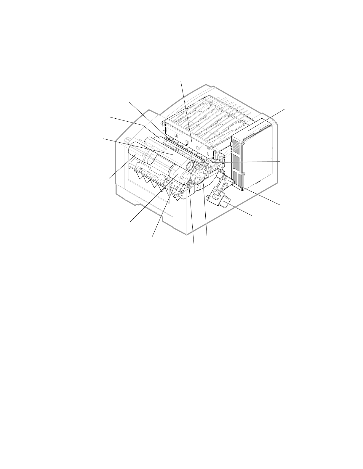
Print engine assemblies
Cap/wipe/purge
assembly
Drum
Transfix
roller
Ink load
assembly
Power
supply
Printhead
Process
motor
Y-axis motor
Paper
pre-heater Drum
Figure 1-2 Internal features of the print engine
X-axis
drive
X-axis
motor
Maintenance
tray
heater
9100-02
1-4
Phaser 340 Color Printer
Page 21
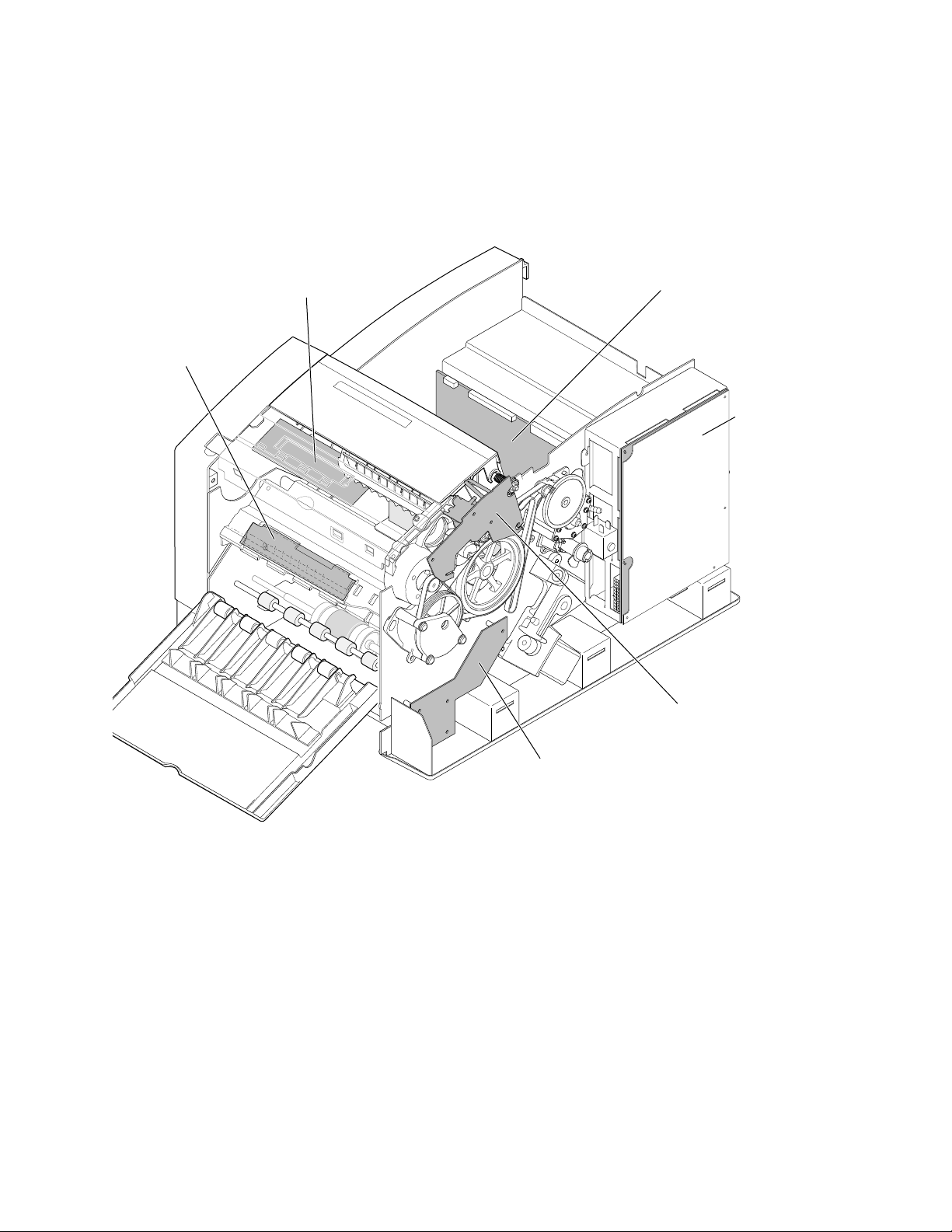
I/O Board 4
General Information
Ten circuit board support the printer’s electronics. Four board, called
I/O board 1 through I/O board 4 supports the front panel, solenoids and
sensors. The main board contains the printer’s two CPU processors, a
29K processor which executes the PostScript image processing and a
68K processor which controls the print engine.
Front panel
Power
control board
1
Power supply
Figure 1-3 Circuit boards of the print engine (right front view)
I/O Board 3
I/O Board 2
9100-94
Service Manual
1-5
Page 22
General Information
1
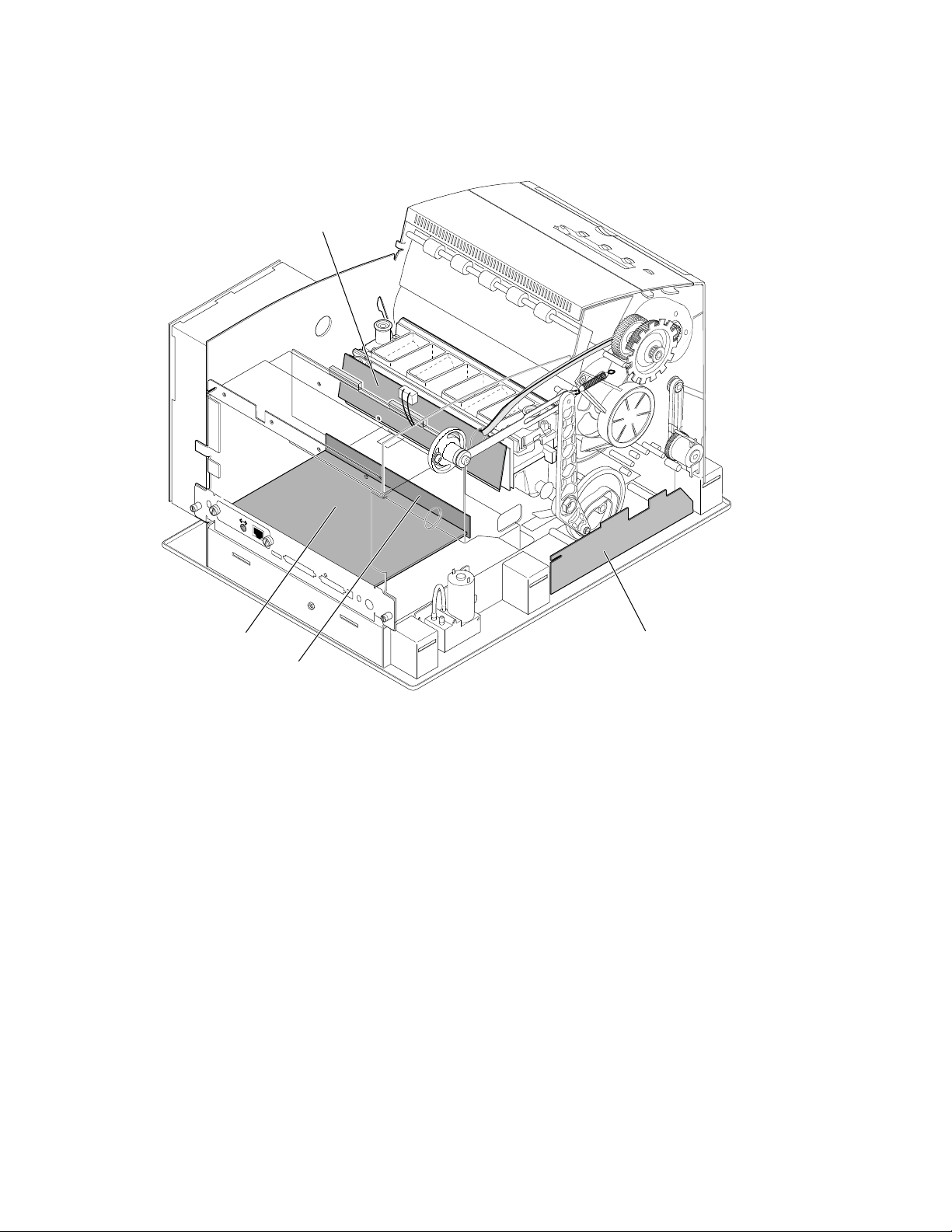
Printhead drive board
Ethernet®
Smart Card
PHASER 340
Service
port
MODEL 4682 PXi
Parallel
SCSI Disk
DIP
AUX
Feeder
Main board
Interconnect board
Figure 1-4 Circuit boards of the print engine (left-rear view)
I/O Board 1
9100-38
1-6
Phaser 340 Color Printer
Page 23
General Information
An internal data bus, called the I
2
C bus, connects all I/O boards to the main
board. Through this single bus, the main board can “poll” the I/O boards for the
state of the printer’s sensors as well as actuate the printer’s solenoids. This data
bus greatly simplifies the wiring that would otherwise be required for
monitoring dozens of sensors and actuating solenoids.
1
Figure 1-5 The printer’s I
2
C bus
I2C bus
9100-04
Service Manual
1-7
Page 24
General Information
1
The printer features a printhead maintenance system used to clean the printhead
faceplate and clear clogs from the printhead nozzles. The system consists of a
vacuum pump, a vacuum accumulator, a solenoid valve and a cap/wipe/purge
assembly.
Cap/wipe/purge
assembly
Air valve
Ethernet®
Smart Card
PHASER 340
Service
port
MODEL 4682 PXi
Parallel
SCSI Disk
Vacuum
accumulator
DIP
AUX
Feeder
Figure 1-6 Printhead maintenance system of the print engine
Air pump
9100-03
1-8
Phaser 340 Color Printer
Page 25
Drum home position
sensor
Drum encoder
sensor
Transfix gear
position sensor
Paper preheat
exit sensor
Paper preheat
entry sensor
Left maintenance
tray sensor
General Information
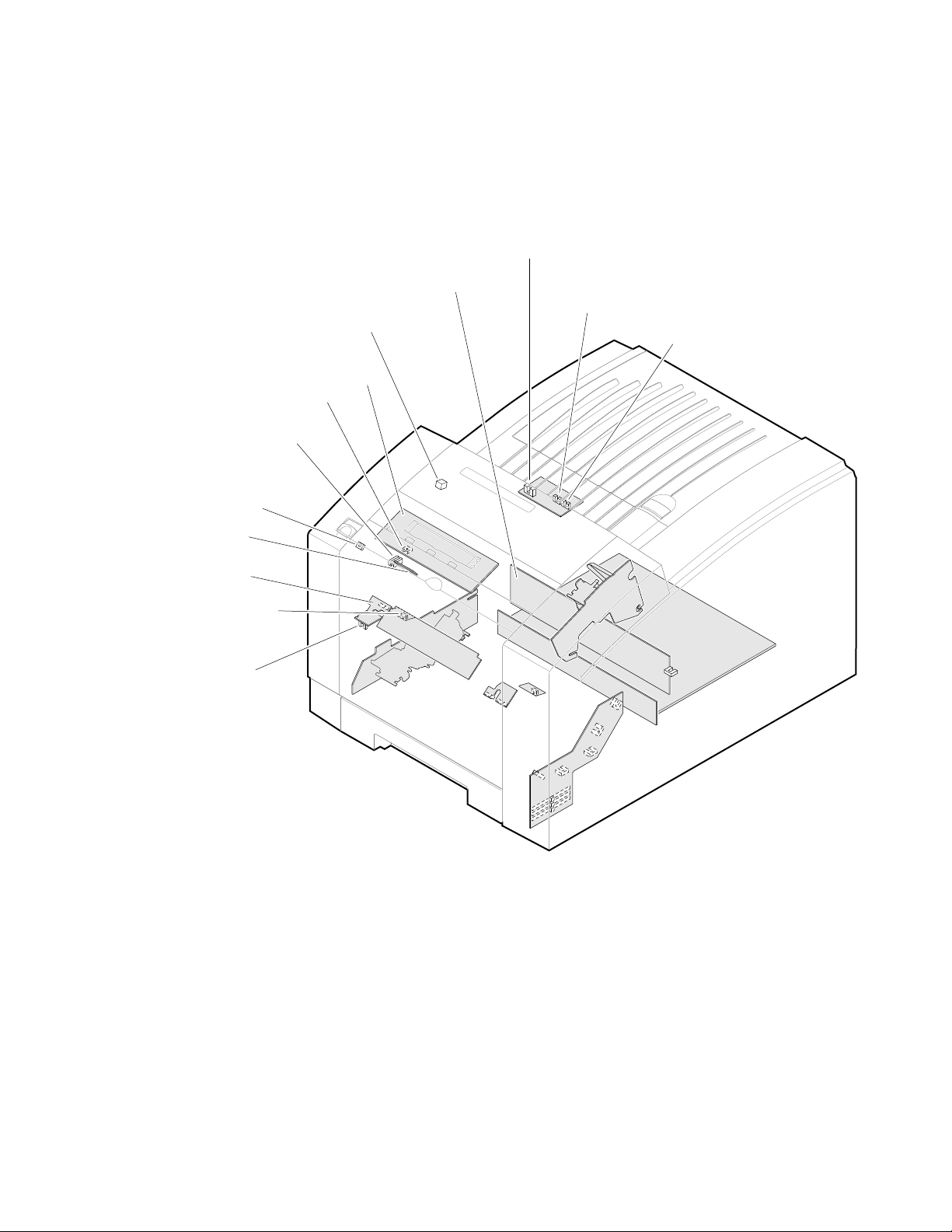
Sensors in the printer provide information to the main board to determine the
state of the printer. The printer monitors the positions of some of the movable
assemblies, such as the drum, as well as the temperature of many other
assemblies, such as the printhead, paper preheater and the drum.
Ink load door
sensor
Ink stick out
sensors
Ink stick low
sensors
Front panel
Drum
temperature
sensor
Power
control
board
1
Front cover and
handfeed sensors
Figure 1-7 Left-side sensors and switches on the print engine
9100-72
Service Manual
1-9
Page 26
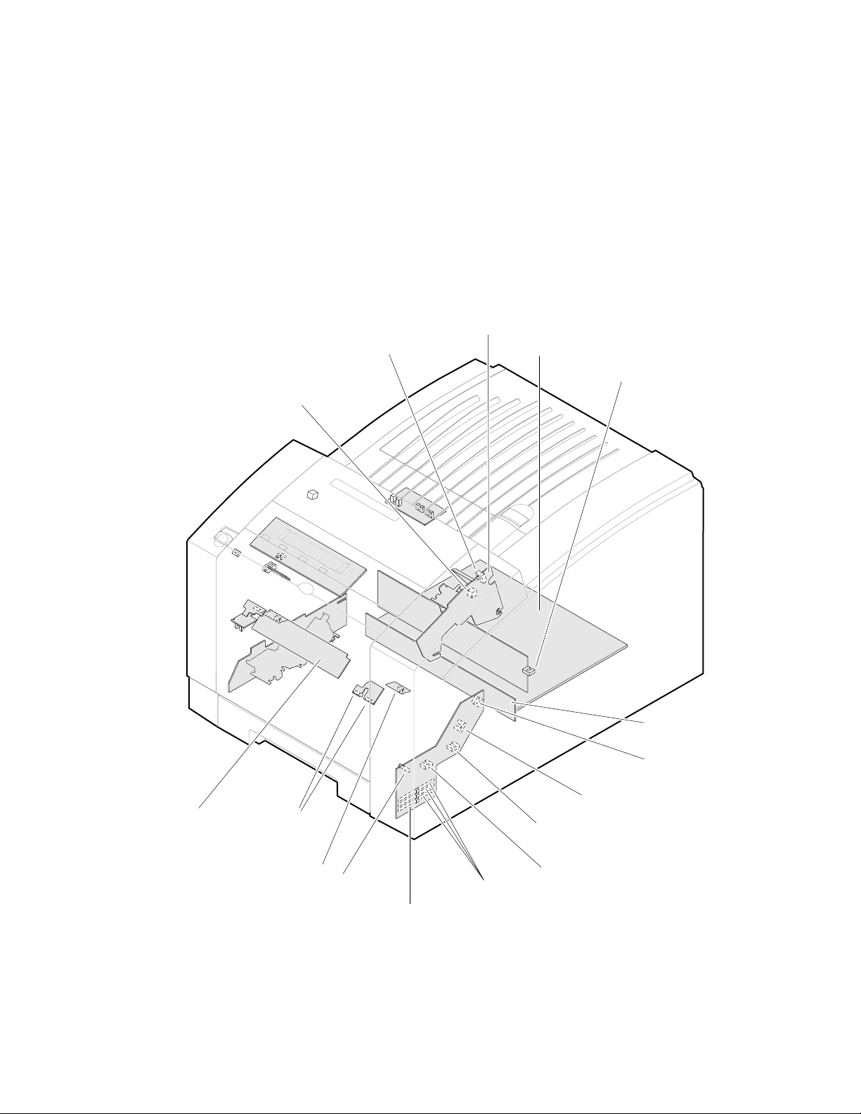
General Information
1
Caution
Stripper cover
opensensor
The actual position of some printer assemblies, such as the
printhead or the cap/wipe/purge assembly, cannot be ascertained at
all times. The printer records, in NVRAM, where it last positioned
such assemblies each time it moves them. If, after power-down or a
power interruption, the assemblies are manually repositioned, the
printer erroneously assumes that the assemblies to be in the
position it last left them. This assumption can result in damage to
the printer when it tries to position the assemblies. For example,
the printhead could be tilted forward and crash into the raised
cap/wipe/purge assembly.
Paper exit
sensor
I/O Board 3
Main board
Printhead
lock sensor
I/O Board 4
Paper width
sensors
Right
maintenance
tray sensor
Paper-pick
sensor
I/O Board 2
Figure 1-8 Right-side sensors and switches on the print engine
1-10
Phaser 340 Color Printer
Interconnect
board
X-axis
home sensor
Cap wipe/purge
assembly home sensor
Maintenance tray
blade position sensor
Paper-empty sensor
Tray type sensors
9100-73
Page 27
Head tilt
solenoid
Maintenance tray
camshaft
solenoid
General Information
1
Paper pick
solenoid
Transfer cam
solenoid
Figure 1-9 Solenoids on the print engine
Air valve
9100-05
Service Manual
1-11
Page 28
General Information
1
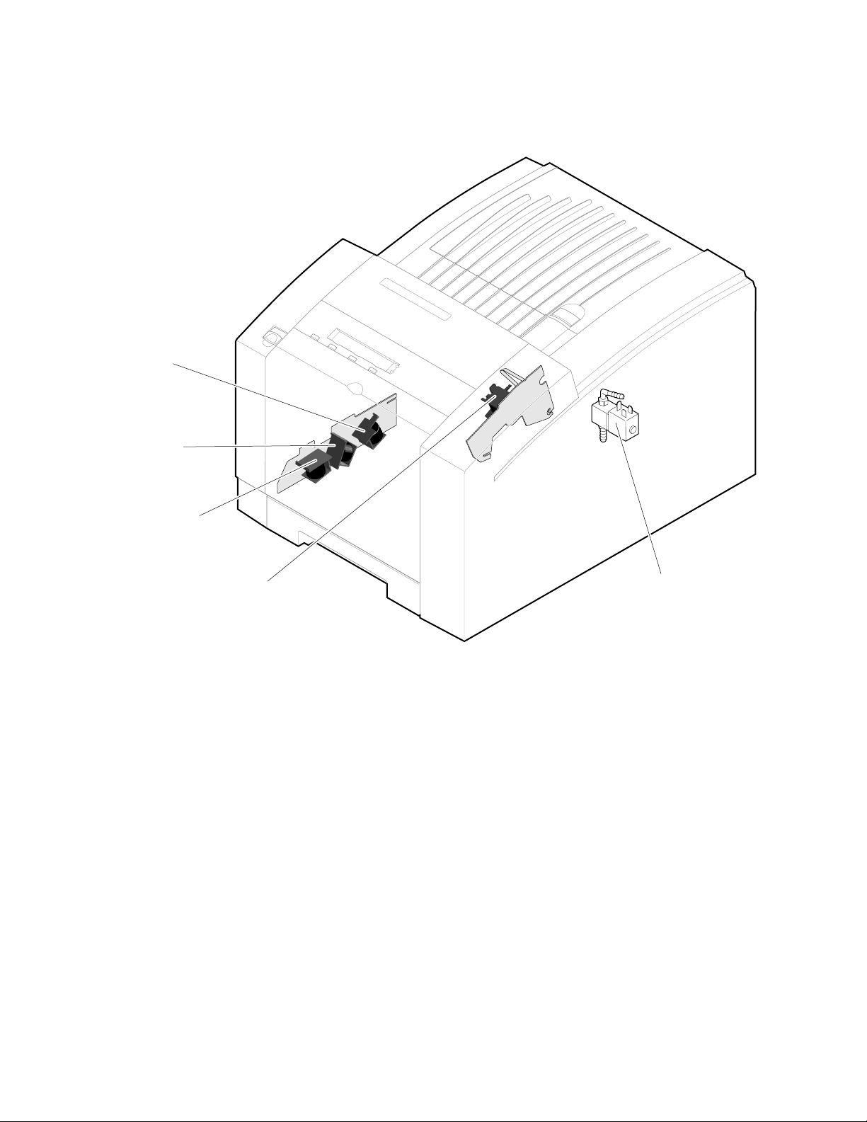
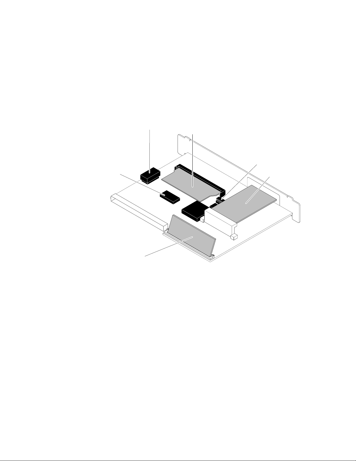
The main board
The main board features two processors: one processor controls the functions of
the print engine and the other provides PostScript image processing. Prominent
on the main board is the ROM code SIMM and the RAM SIMM plug-in
modules. Network connection is provided through the plug-in network card.
The printer stores unique printer status and PostScript values in its NVRAM
module. The printer’s IP address, unique to each printer, is stored in a socketed
ROM IC.
NV RAM
Print engine
ROM
RAM SIMM
Figure 1-10 Features of the main board
PostScript
ROM
Printer ID ROM
Network card
9100-06
1-12
Phaser 340 Color Printer
Page 29

Combination sensors and their meanings
Combinations of sensors are used by the printer to determine the type of
standard media tray installed in the printer.
Media tray type sensing
The combinations of the three tray sensors “tell” the print engine what type of
standard media tray is installed. (The print engine does not detect the type of
media installed in the tray; it only detects the particular tray being used.) The
tray sensors are located on the right-side interior of the paper tray slot, mounted
on I/O board 2. There are four tray types:
■
Letter (A-size). This tray is sized for 8.5 x 11-inch (Olympic) paper.
Metric Letter (A4-size). This tray is used for 210 x 297 mm (Metric)
■
paper.
Transparency (A). This tray supports Olympic-size transparency film.
■
General Information
1
■
Transparency (A4). This tray supports Metric-size transparency
film.
Table 1-1 Tray switch sensor combinations
Tray type
Top switch
Middle switch
Bottom switc h
A Paper A4 Paper A Transparency A4 Transparency
Closed Open Closed Open
Open Closed Open Closed
Open Open Closed Closed
Service Manual
1-13
Page 30
General Information
On
1
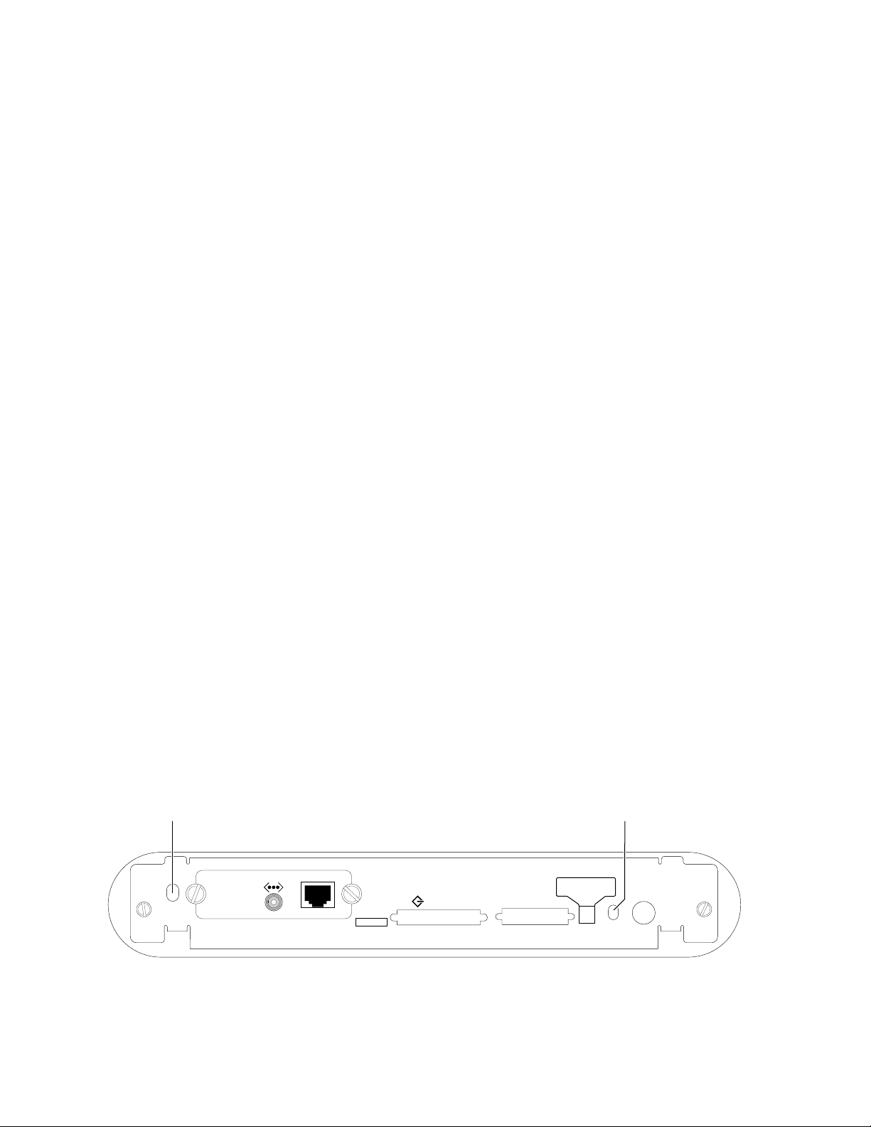
Rear panel
Connectors
The rear panel of the printer features the host interface connectors to the printer;
it includes the following connectors:
Standard parallel (high-density connector)
■
■
SCSI high-density connector (font hard disk drive only)
With the addition of a Phaser Share network card, the printer can feature either
of these connector combinations:
RS-232 serial and LocalTalk connectors
■
■
ThinNet (10base2) and Twisted Pair (10baseT) Ethernet connectors
29K processor
health light
Health LEDs
Two health LEDs indicate the status of the printer’s two CPU processors (a 29K
and a 68K processor).
Blinking : The printer is operating normally. Both LEDs blink
■
irregularly during diagnostics.
If a soft error occurs, the image processor’s 29K operates, but in a
reduced capacity. Soft failures include failure of expansion memory
SIMMs or any of the interface ports. When a soft error occurs, the
printer automatically prints a startup page listing the error.
■
or Off, or blinking a coded error indication : A hard error condition has
occurred that would keep the image processor board from operating.
Refer to the Chapter 6 topic “Verifying main board CPU operation” on
page 6-3 for the meaning of a coded indication.
The following figure illustrates the rear panel of the printer.
68K processor
health light
Ethernet®
PHASER 340
Service
port
Figure 1-11 Printer rear panel with the optional Ethernet card
1-14
Phaser 340 Color Printer
SCSI Disk
Parallel
1
Service2Reset
DIP
AUX
Feeder
9100-07
Page 31

Front panel
General Information
These front panel features are found on the printer:
■
A two-line, 24-character LCD
Four push buttons
■
■
Two LEDs
LCD.
The LCD serves two purposes: displaying current image processor and
print engine status information and displaying an interactive menu. Status
information includes image processor status such as
Printing . Print engine status includes messages such as Out of paper ,
and
Ready , Receiving data
Paper Jam , and Add ink .
The interactive menu can only be entered while the printer is idle and ready.
The interactive menu has two modes, review and modify. Customers can review
and modify certain NVRAM, I/O ports and peripheral parameters. Using the
front panel to review and change parameters is discussed in Chapter 9, “Check
and Adjustments.”
1
Buttons.
Button 1, the left-most button, is an Exit key used to cancel an operation
while in the interactive menu. The functions of buttons 2, 3 and 4 are defined by
the particular menu or function being displayed on the LCD. The bottom row of
the LCD labels the current function of each button.
In addition, pressing the buttons as you turn on the printer enables certain
diagnostic modes.
Pressing and holding Button 1, as you turn on the printer, skips
■
power-up diagnostics.
Pressing and holding Button 2, as you turn on the printer, executes
■
extended diagnostics.
The Chapter 9 topic “Resetting NVRAM” on page 9-21 explains how to use the
front panel buttons to reset the NVRAM to its factory default values.
Ready
Clean Menu
Exit
Power
Error
Figure 1-12 Printer front panel
Service Manual
9100-08
1-15
Page 32

1
General Information
Specifications
These specifications apply to the printer.
Table 1-2 Physical dimensions
Dimensions Value
Height: 33 cm. (13 ins.)
Width: 40 cm (15.7 ins.)
Depth: 50.2 cm (19.7 ins.)
Weight: Approximately 32 kgs (70 lbs). Print engine weight only; add
45.7 cm (18 ins.) with Lower Paper Tray Assembly
7 kgs (15.5 lbs.) for optional Lower Paper Tray Assembly.
Table 1-3 Printer clearances
Clearances Value
Top: 45.7 cm (18 ins.)
Left: 10.2 cm (4 ins.)
Right: 10.2 cm (4 ins.)
Front: Unrestricted to replace trays and clear paper jams
Rear: 10.2 cm (4 ins.)
Bottom: No obstruction under printer that could block its cooling
Mounting surface
flatness:
vents.
Within 3 degrees of horizontal with all four feet in contact with
the surface. The printer should not be tilted more than 15
from horizontal for more than 1 minute while the printer is idle
or the ink is hot (in liquid state) or if the maintenance tray is
installed.
o
1-16
Phaser 340 Color Printer
Page 33

Table 1-4 Functional specifications
Characteristic Specification
Printing process Solid ink-jet onto plain paper.
General Information
1
Color medium Cyan, magenta, yellow and black ink sticks, each
Addressability Selectable 300 x 300 or 600 x 300 dots-per-inch (horizontal
Engine printing speed The time it takes from loading to ejecting:
Minimum printing
margins
Maximum print area A-size: 8.1 x 10.4 in.
Usable paper weights Tray fed: 16 - 32 lb Bond (60 - 120 g/m
shape-coded. The printer uses the subtractive color system
to produce the colors red, green, and blue. Only black ink is
used to create the color black.
and vertical). Only Phaser 340 Plus configuration can print at
600 x 300 dpi.
300 dots per inch:
on A- or A4-size: ≈15 seconds per print
600 dots per inch:
on A- or A4-size: ≈ 30 seconds per print
Transparency film printing:
on A- or A4-size: ≈ 30 seconds per print
Print times do not include processing time by the image
processor, which varies, due to image complexity.
All sides: 5 mm (0.2 in.) e xcept bottom which is 7 mm (0.7 in.)
2432 x 3134 pixels
A4-size: 200 x 283 mm
2368 x 3342 pixels
2
)
Manual fed: 16 - 32 lb Bond (60 - 120 g/m
50 - 80 lb Cover (135 - 220 gm
2
)
2
)
Service Manual
1-17
Page 34

1
General Information
Table 1-5 Electrical specifications
Characteristic Specification
Primary line voltages 87 to 132 VAC (115 VAC nominal)
Primary voltage
frequency range
Power consumption 300 watts at idle; 600 during printing. Maximum power
Current rating 115 VAC configuration – 5.7 amp max./1 amp min.
Fusing F1: DC switcher - 6.3 amp slo-blo
Secondary voltages +5
RF emissions Both 115 and 220 VAC-configured instruments pass these
174 to 264 VAC (220 VAC nominal)
Input voltage range is switch-selectable.
47 to 63 Hz
consumption 1000 watts during warm-up.
220 VAC configuration – 3.6 amp max./1 amp min.
F2: Jet stack left and right - 6.3 amp fast-blo
F3: Ink melt chambers,
cap/wipe/purge assembly - 6.3 amp fast blo
F4: Ink reservoir - 10 amp slo-blo
F5: Drum heater - 6.3 amp slo-blo
Fuses are not user-accessible.
V ± 2%
+12 V ± 5%
-12 V ± 5%
+40 V -5%, +12%
-40 V ± 10%
+54 V ± 10%
standards: FCC Part 15 Class B
EN55022 (CISPR 22) Class B
VCCI (CISPR 22) Class B
1-18
Phaser 340 Color Printer
Page 35

Table 1-6 Environmental specifications
Characteristic Specification
General Information
1
Temperature
Operating
Storage and shipping
Humidity
Operating
Non-operating
Altitude
Operating
Non-operating
Vibration/shock
Non-Operating
(vibration)
Non-operating (shock)
Operating (shock)
Acoustic Noise
(operating)
15 to 35 C
-30 to 60
°
(59 to 95° F)
°
C (-22 to 140° F)
10 to 80% relative humidity, non-condensing
10 to 95% relative humidity, non-condensing
0 to 2400 m (8,000 ft.) at 25
°
C
0 to 15000 m (50,000 ft.)
Will withstand 0.15G excitation, 5 to 200 Hz, 3 axes for up to
7 minutes with no impairment or subsequent damage.
0.5 g, 25 minute sweep, 5-200-5 Hz, 100-200 sec/sweep
cycles
The printer may have any corner raised and dropped 1.5 cm
(0.6 in.) while printing is in progress, without impairment of
operation that cannot be recovered by a printhead purge
cycle. The printer may have any corner raised and dropped
6 cm (2.4 in.) while idle without subsequent impairment of
operation.
Aver age sound le v el (LEQ) is less than 50 dbA. Peak noise is
55 dbA.
Service Manual
1-19
Page 36

1
General Information
Regulatory specifications
The Phaser 340 is in conformance with the following regulatory standards:
■ FCC Part 15 Class B (for 115 VAC equipment)
■ EN55022 (CISPR 22) Class B
■ VCCI (CISPR 22) Class B
■ The packaged product meets National Safe Transit Committee Test
Procedures
Listed:
■ UL 1950 Information Technology Equipment
Certified to:
■ CSA C22.2 No. 950 Safety of Information Technology Equipment,
Including Electrical Business Equipment
GS licensed:
■ IEC 950 (1991) Second Edition; EN60950 Information Technology
Equipment
1-20
Phaser 340 Color Printer
Page 37

Chapter
2
Installing the Printer and
Drivers
This chapter discusses installing the printer and its drivers as a part of the
S0 installation option. Tektronix Service Option S0 consists of three main
functions detailed in this and the next two chapters of this manual:
■
Chapter 2 “Installing the Printer and Drivers.” The first portion of
installation instructions, this chapter, consists of five basic processes:
Pre-installation interview. This is a phone interview to verify that the
■
customer is ready for the printer. The interview verifies that the
customer has a suitable place for the printer with the proper
environment. The call also verifies that any assistance, such as network
system administration, will be available for the scheduled installation
and that all necessary cables will be available.
■
Unpacking. This is the procedure for taking the printer out of its
shipping box.
■
Testing. This checks that the printer works properly prior to connecting
it to a host computer.
Cabling and configuring. This discusses setting up the printer for
■
communicating to the appropriate host computers.
Loading drivers. This covers installing software on the host computers
■
and configuring the host applications to drive the printer.
Following these steps, proceed to Chapter 3 and then Chapter 4.
■
Chapter 3 “Verifying the Printer and Its Hosts” explains how to verify
that the printer, the host driver and the connection between them
functions correctly.
■
Chapter 4 “Key Operator Training” gives a procedure for training
customers to use and care for the printer.
Service Manual
2-1
Page 38

Installing the Printer and Drivers
2
Pre-install questions for customers
Prior to installing the printer, you should contact the customer and verify that he
or she has prepared an appropriate location for the printer. You will also want to
ensure that you have all the information you need to install the printer at the
customer's site.
Ask the customer the following:
Customer's name
Address ___________________________________________________________
Phone number _____________________________________________________
What type of computers will be networked to the printer?
■
■
Which type of host-to-printer connection will be used:
■
What kind of network environment will the printer be installed into?
■
In the event that the printer is to be installed into a network
environment, will a network administrator be available to help in
assigning network names and addresses for the printer?
Administrator's name__________________________
Phone Number________________________________
___________________________________________________
❏
PC ______________
❏
UNIX____________
❏
serial
dware Protocols
Har
❏
LocalTalk
❏
Token Ring
❏
ThinNet (10Base2)
❏
Twisted Pair (10BaseT)
❏
Macintosh___________
❏
other _______________
❏
parallel
❏
EtherTalk
❏
TCP/IP
❏
Novell NetWare
❏
other _______________
2-2
In the event that the printer is to be installed in a TCP/IP network, has
■
the network administrator assigned a printer name and the
appropriate addresses for the printer?
What software application packages will be used with the printer?
■
(Some applications require special printing utility files.)
_____________________________________________
Phaser 340 Color Printer
Printer Name _____________________
Printer IP address__________________
Net Mask _________________________
Broadcast address _________________
Gateway__________________________
Page 39

Installing the Printer and Drivers
Will the application(s) and sample files be available at the time of the
■
installation to send test files to the printer? _______________________
Will a SCSI font disk be installed on the printer? __________________
■
■
For installations using the printer’s built-in Ethernet interface, you
should inform the network administrator of the printer's
preconfigured Ethernet address; it is printed on the configuration
page.
■
Does the customer have the appropriate power outlet available? The
printer's AC power input is set for these voltages:
115 VAC (87 to 128 VAC)
220 VAC (174 to 264 VAC)
If necessary, refer to the later topic, “Selecting the AC input voltage.”
Did the customer order the correct power cord?
■
_______ U.S. Standard (161-0230-01)
_______ European Option A1 (161-0104-06)
_______ United Kingdom Option A2 (161-0066-10)
_______ Australian Option A3 (161-0104-05)
_______ Swiss Option A5 (161-0154-00)
2
Customers must provide the particular interface cable or network
■
adapter they need to use with the printer. Customers can purchase the
following from the Tektronix Graphics Supplies Order Desk by calling
1-800-835-6100.
Parallel cable, DB25-pin plug to Centronics 1284C 012-1468-00
■
■
Serial, 9-pin to 9-pin, 3 m (10 ft.), null modem 012-1379-00
Serial, 9-pin to 25-pin, 3 m (10 ft.), null modem 012-1380-00
■
For AppleTalk installations,
customers must provide the appropriate
network adapter to the printer's 9-pin circular LocalTalk connector.
Customers can obtain an adapter from their dealer. For Ethernet
networks,
customers must provide the appropriate network cables to
connect to the printer’s ThinNet or Twisted Pair connector.
Service Manual
2-3
Page 40

Installing the Printer and Drivers
2
The printer requires the following environmental conditions:
■
Temperature: 15 to 35
Humidity: 10 to 80% relative humidity, non-condensing
■
■
Power: 115 VAC or 220 VAC. The printer requires about 10 amps of
o
C (59 to 95
o
F)
current at full load in 115 VAC mode; 5 A at 220 VAC mode.
■
Clearances: A space measuring 46 cm wide by 92 cm deep by 76 cm
high (18 ins. wide by 36 ins. deep by 30 ins. high). The space in front
of the printer accounts for enough clearance to install the paper tray.
The extra height is to install the ink sticks.
■
Weight support: 45 kgs (100 lbs.)
Driver software must be installed on the host computer to use the printer’s
fullest potential. A host computer must meet the following conditions:
Mac
Mac II, Performa, Centris, Quadra or PowerMac
■
■
Operating System 6.0.7 or later
4 Mbytes RAM
■
PC
■
IBM AT, PS/2 or compatible, with a 386 or later CPU, a 3.5-inch floppy
disk drive, and a hard disk drive, 2 Mbytes RAM, 2 Mbytes of hard
disk space
DOS systems
DOS 3.1 or later
An application that supports color PostScript or HP-GL
Windows systems
Windows 3.1
Windows 95
OS/2
Windows for Workgroups 3.11
Windows NT and Daytona
2-4
Phaser 340 Color Printer
Page 41

Installing the Printer and Drivers
Workstation
UNIX workstations: The X Window System,
■
SUN workstations: Solaris 1.1 (BSD), Solaris 2.x (Sys V, optional LPD
support required)
DEC: Ultrix, VMS, OpenVMS
HP: HP-UX
SGI: IRIX
IBM RS6000: AIX (optional LPD support required)
■
750 kbyte hard disk space for files
Based on the results of the pre-install interview with the customer, you may wish
to access the Tektronix Highly Automated Library (HAL) during business hours,
at 1-800-835-6100 (ask to be transferred to HAL) for articles that may help with
installing the printer into a customer's network. You can call HAL directly at
(503) 682-7450, 24 hours a day, 7 days a week. The articles can be faxed to you in
just minutes. HAL may also have articles that may be of interest to your
customer, such as printing from a specific application. (This is a good way of
introducing the HAL system to the customer.) Outside of the U.S. you may use
EuroHAL. Refer to the Chapter 4 topic, “Using the automated fax systems” on
page 4-7.
2
Service Manual
2-5
Page 42

Installing the Printer and Drivers
2
Unpacking
Inventory for printer
■
■
■
■
■
■
Printer
A-size paper tray (or A4)
Power cord
TekColor Care envelope (includes a printer registration card)
Cleaning kit
Supplies information sheet
Ink sticks
■
■
Maintenance tray
Paper sampler
■
■
User manual
Installation instructions
■
■
Printer drivers and utilities reference manual
Phaser printing utilities and driver diskettes
■
■
Optional Lower Paper Tray Assembly (with paper tray)
Phaser Share network utilities user manual (optional)
■
■
Phaser Share utilities diskette (optional)
2-6
Phaser 340 Color Printer
Page 43

Installing the Printer and Drivers
2
Figure 2-1 The printer packaging
9100-09
Service Manual
2-7
Page 44

Installing the Printer and Drivers
1.
2.
3.
5.
6.
2
Setting up the printer
Installing the printer is explained in detail in the Phaser 340 Color Printer User
Manual
the printer.
. The following is a brief list of the steps you follow to unpack and set up
Remove the printer from its shipping box and place it in its working
location. If the Lower Paper Tray Assembly was also purchased, place
the Lower Paper Tray Assembly in the working location and then
install the printer on top of it.
Install the paper tray(s) in the printer.
Unlock the transit restraint lock on the right side of the printer.
2
Figure 2-2 Unlocking the transit restraint lock
4. AC voltage selection:
side of the printer. Ensure that it is set to the correct voltage for the
customer's installation (either 115 VAC or 220 VAC).
Ensure that the power switch is off .
Plug the printer's power cord into the printer's AC receptacle. Plug
the other end into an appropriate AC power outlet.
Locate the AC voltage select switch on the right
3
9101-03
2-8
Phaser 340 Color Printer
Page 45

7.
Installing the Printer and Drivers
Install the printer’s maintenance tray and paper tray. Note that when
a new maintenance tray is installed, the printer requires a 15-minute
wait before it will print.
8. Installing RAM SIMMs
. The standard configuration of the printer
includes 8 Mbytes of RAM. This can be supplemented with a 4- or
16-Mbyte RAM SIMM. To install the optional memory, refer to the
Chapter 8 topic, “RAM SIMM” on page 8-61.
9. Installing a network card
. Network support is provided via three
optional Phaser Share Network Interface plug-in cards.
■
The LocalTalk/Serial Card supports AppleTalk/LocalTalk protocols
and RS-232 serial connectors.
The Ethernet Interface Card supports the EtherTalk, Novell NetWare,
■
and TCP/IP protocols.
■ The Token Ring Network Card supports Novell NetWare, TokenTalk
and TCP/IP protocols.
2
To install a network card, refer to the Chapter 8 topic, “Network card”
on page 8-63.
10.
Following RAM SIMM or network card installation, turn on the
printer to ensure that the card works properly. The printer executes a
power-up self-test and prints a startup page. If the printer fails its
self-test, refer to Chapter 6, “Troubleshooting.” The printer can take
up to 15 minutes to warm up from a cold start.
11.
Turn off the printer and connect the printer to a host.
Service Manual
2-9
Page 46

2
Installing the Printer and Drivers
Cabling the printer
Note
This topic explains making a hardware connection between the printer and its
host computer, setting the communication parameters for the printer's serial and
parallel ports to be compatible with the user's host computer and driver
installation. This topic is divided into three main parts: Macintosh, PC, and
workstation.
Carry spare serial and parallel cables and network adapters.
You can use them if you encounter a defective cable or as an alternate
means of testing the printer-to-host communications.
Connecting the printer to a Macintosh
LocalTalk connection to a Macintosh
1.
Turn off the printer. LocalTalk protocol requires that you attach the
LocalTalk cable with the printer powered off.
2.
For a direct connection, attach the interface cable or adapter to the host
computer's LocalTalk port. (The port has a printer icon printed next to
it.) Attach the other end to the printer’s LocalTalk port.
For a LocalTalk network connection, attach the network adapter to the
printer's LocalTalk port.
3.
Turn on the printer and the computer.
Ethernet connection to a Macintosh
Note
1.
2.
3.
For an Ethernet connection, the printer must have the optional
Phaser Share Ethernet card installed.
Turn off the printer. Ethernet protocol requires that you attach the
Ethernet cable with the printer powered off.
Attach the Ethernet cable to the printer’s Ethernet port. A ThickNet
(10base 5) cable requires a 10base 5 to ThinNet (10base2) or Twisted
Pair (10baseT) network adapter to connect to one of the printer's two
Ethernet connectors.
Turn on the printer. During the printer's boot-up process, the printer's
network name is displayed in the Mac's Chooser and its node address
is resolved with the network. If the network has multiple zones, the
network router assigns the printer a default zone name. The printer’s
configuration page lists the zone name. The Chapter 9 topic, “Printing
the configuration page” on page 9-7, explains printing this page.
2-10
Phaser 340 Color Printer
Page 47

Connecting the printer to a PC
Direct connection to a PC
1.
Turn off the printer. Turn off the host computer.
2.
Attach the parallel interface cable to the host computer; attach the
other end to the printer.
3.
Turn on the printer first and then the computer.
Networked connection to a PC using the printer’s Ethernet port
In the Novell network, the printer is connected to the network in the same
manner as workstations using an Ethernet connection.
1.
Turn off the printer.
2.
Connect the interface cable to the printer’s Ethernet connector.
Installing the Printer and Drivers
2
3.
Turn on the printer.
Connecting the printer to a workstation
Direct connection to a workstation
1.
Turn off the printer. Turn off the host computer.
2.
Attach the parallel interface cable to the workstation; attach the other
end to the printer.
3.
Turn on the printer and the computer.
Networked connection to a workstation
1.
Turn off the printer.
2.
In the case of an Ethernet network, connect the interface cable to the
printer’s Ethernet connector.
3.
Turn on the printer.
Service Manual
2-11
Page 48
2
Installing the Printer and Drivers
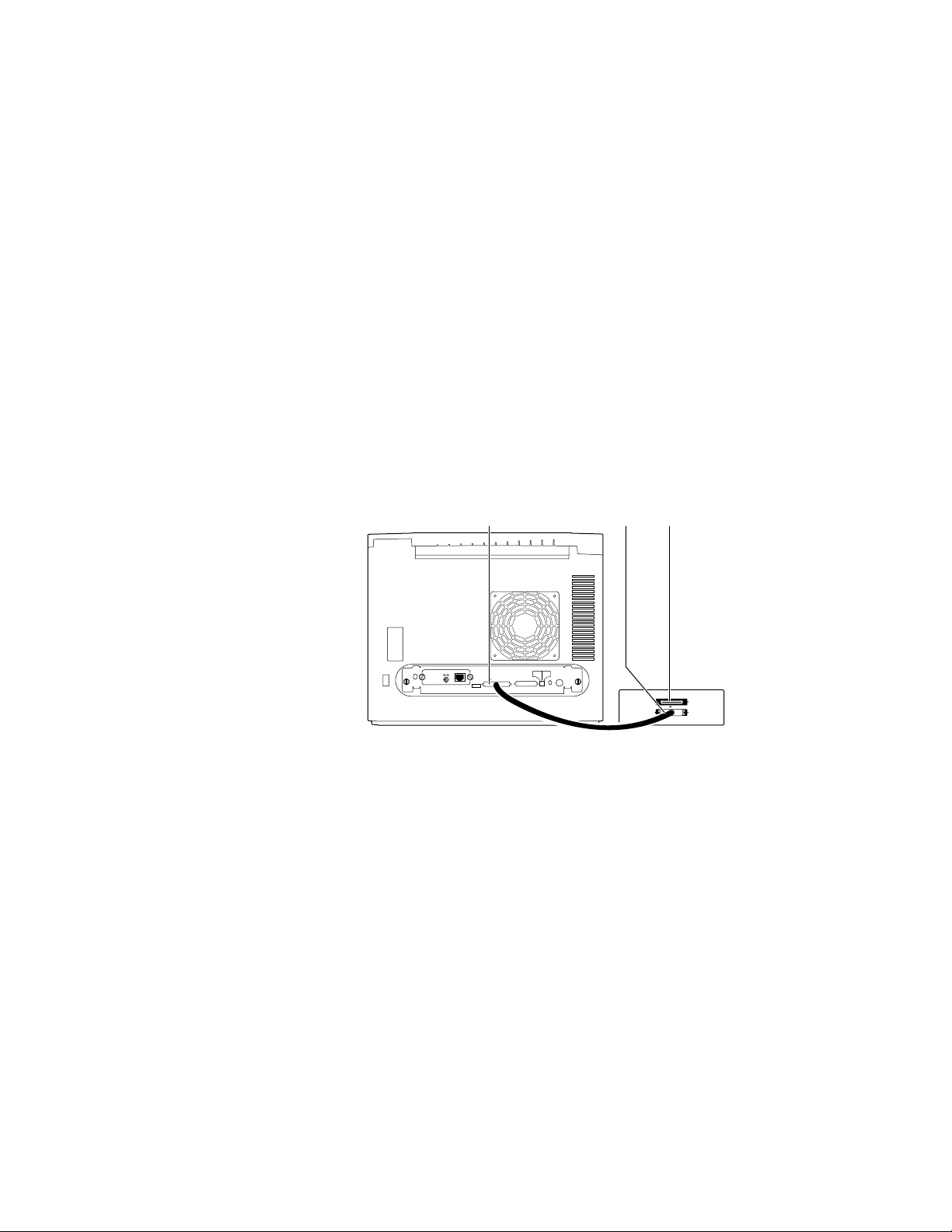
Installing a SCSI hard disk drive on a Phaser 340
Perform this procedure if the customer has a hard disk drive available for font
storage. Otherwise, continue to the next procedure, “Connecting the optional
CopyStation to the printer”.
1.
Make sure that the printer and the SCSI disk drive are turned off.
2.
Attach the SCSI cable to the printer's SCSI port. The printer may
require the SCSI cable (part numbered 013-1465-00) to connect the
drive’s standard 50-pin SCSI connector to the smaller, high-density
SCSI connector on the printer’s rear panel.
3.
Attach the other end of the SCSI cable to the SCSI drive.
4.
Attach a terminator to the SCSI drive's second connector. (This is not
required if the disk drive is internally terminated.)
Phaser 340 SCSI
Disk
drive
SCSI
Terminator
Ethernet®
PHASER 340
Service
Only
Smart Card
1
Service2Reset
Second
SCSI Disk
Feeder
Parallel
SCSI
9100-10
Figure 2-3 Connecting a SCSI hard disk drive to a Phaser 340
5.
Turn on the disk drive first, and then the printer.
6.
Refer to the Phaser 340 Driver and Utilities Printing Reference for details
on formatting a SCSI disk, controlling Sys/Start job files, and using the
LaserWriter Utility to load fonts onto the disk drive.
2-12
Phaser 340 Color Printer
Page 49
Installing the Printer and Drivers
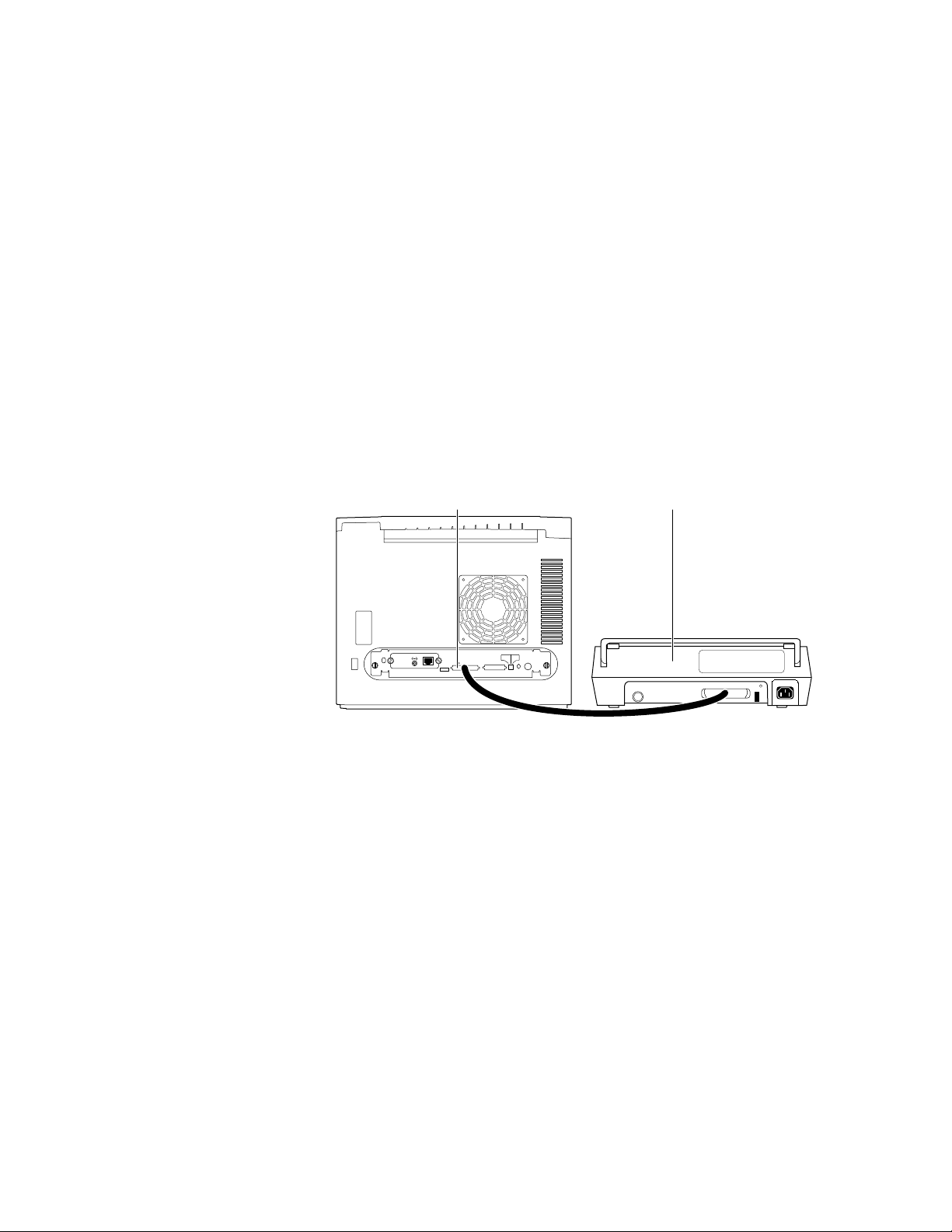
Connecting the optional CopyStation to the printer
Perform this procedure if the customer has purchased a CopyStation.
Otherwise, continue to the next procedure, “Turning on the printer”. The
CopyStation may be “daisychained” with one or more SCSI drives being used
for font storage. Be sure that each SCSI device uses a unique SCSI address
(0 through 4). Installing a CopyStation is fully explained in the Phaser
CopyStation User Manual.
1.
Make sure that the printer and any attached SCSI disk drive are
turned off.
2.
Attach the CopyStation’s SCSI cable to the printer's SCSI port. The
SCSI drive may require the SCSI cable (part numbered 013-1465-00) to
connect the drive’s standard 50-pin SCSI connector to the smaller,
high-density SCSI connector on the printer’s rear panel.
3.
Attach the other end of the SCSI cable to the CopyStation’s SCSI port.
2
Phaser 340 SCSI CopyStation
Ethernet®
PHASER 340
Service
Only
Smart Card
1
Service2Reset
Second
SCSI Disk
Feeder
Parallel
Figure 2-4 Connecting a CopyStation to a Phaser 340
Note
The CopyStation uses two SCSI address; they are preset to 5 and 6.
Make sure that any connected SCSI hard drive does not use these
addresses.
4.
Turn on the CopyStation (and any hard drives) first, and then turn on
the printer.
5.
Refer to the Phaser CopyStation User Manual for details.
9100-11
Service Manual
2-13
Page 50

2
Installing the Printer and Drivers
Turning on the printer
Startup page
When you turn on a Phaser 340 printer, it executes a series of self-tests to
determine if there are any problems with the PostScript interface. After running
self-tests and reaching the “Ready” state, the printer prints a startup page (if the
startup page has been enabled). After running self-tests and printing the startup
page, the printer is ready for operation. A downloadable PostScript utility file,
found on the Drivers and Utilities diskette, allows you to enable or disable the
startup page. Alternately, you can disable the startup page using the front panel
menu; refer to the Chapter 9 topic, “Front panel menu” on page 9-2.
The startup page provides valuable information about the printer:
■ Fonts
■ Ports (Serial, Parallel, LocalTalk, Ethernet)
■ Printer name
■ Ethernet protocols
■ TekColor corrections and print quality mode
■ Pages printed
■ RAM installed
■ Tektronix version firmware
■ Adobe PostScript version software
■ Printer ID
■ Authorization code
■ SCSI disk attached
If the printer detects a non-fatal error at power-up, the startup page prints with
an error message printed in red; this is true, even if the startup page has been
disabled; the printer will still force a print to report the error.
Message Description
Serial, Parallel, LocalTalk, EtherTalk, or
SCSI Port failed
DRAM SIMM failed The memory SIMM is not working. Since
The named port is not working. The other
ports can still be used.
the printer’s base memory is still working,
the printer can still be used, but large
images may not print, special imaging
features may not work and throughput may
be reduced.
2-14
Phaser 340 Color Printer
Page 51

Configuration page
Installing the Printer and Drivers
To provide further diagnostic information, the printer can print a configuration
page. The configuration page lists the values that the printer stores in its
NVRAM as well as those of an installed network card’s NVRAM. These values
can be informative when troubleshooting the printer, particularly networked
operations. To print a configuration page, while the printer is powered-up and
idle, scroll through the front panel menu and select Configuration Page from the
Test Prints menu. Refer to the Section 9 topic, “Printing the configuration page”
on page 9-7.
The configuration page gives the following information:
■ General information about the printer, such as print count, the
assigned name, Ethernet address, the authorization code (if loaded),
timeouts, number of fonts, and total memory
■ Color settings such as Photofine enabled and Vivid Color
■ Serial port settings (if installed)
2
■ Parallel port settings
■ LocalTalk port settings (if installed)
■ EtherTalk settings (if installed)
■ TCP/IP settings (if installed)
■ Novell NetWare settings (if installed)
Table 2-1 Configuration page settings
Parameter Description Saved
in
NVRAM
Printer type The name of the product. yes Phaser 340 or
Printer name The current name of the printer as
Pages printed Total number of prints processed
PostScript FW
version number
seen on a network.
through the image processor.
Tektronix version number of the
PostScript firmware running on the
printer’s 29K processor.
yes <printer name>
yes 0
no not applicable
Default Limits or alternate choices
Phaser 340 Plus
the default is the
same name of the
product
Any name defined by the user
up to 31 characters in length.
Print engine FW
version number
T ektronix v ersion number of the engine
firmware running on the printer’s 68K
processor. Read from ROM and
stored in NVRAM.
yes not applicable
Service Manual
2-15
Page 52

2
Installing the Printer and Drivers
Table 2-1 Configuration page settings (cont'd.)
Parameter Description Saved
in
NVRAM
High altitude
flag
Startup page
enabled
Printer ID The Ethernet address provided for
Authorization
code
Fonts in ROM Number of font stored in the printers
Job Timeout Amount of time a job can take to
Wait Timeout Amount of time the image processor
Manual Feed
time-out
Flag indicating whether or not the
printer has been set to operate
optimally for high altitudes.
Indicates if the printer prints a startup
page upon power-up.
each printer.
A unique number downloaded to the
printer (in the field or at the factory) to
enable TCP/IP protocols.
ROM memory.
process.
will wait for additional data from a host.
Amount of time allowed to install a
sheet of media in the manual feed tray.
yes Off On
yes Yes No
yes In the format
yes 0000-0000-0000-
yes 0 seconds Any value denoted in
yes 40 seconds Any value denoted in
yes 60 second Any integer, denoted in
Default Limits or alternate choices
xx:xx:xx:xx:xx:xx
Valid code number
0000-0000-00000000
17 52 or 69
seconds; 0 means unlimited
amount of time.
seconds; 0 means unlimited
amount of time.
seconds. 0 indicates an
unlimited amount of time.
Energy Star
time-out
Media tray Indicates the default media tray. yes Upper Lower, Auto
RAM memory Total amount of RAM on the image
Color
Correction
Parallel port
interpreter
Parallel port
Encoding
Parallel port
mode
Parallel port
back channel
Amount of idle time allowed before the
printer switches to a low energy power
mode.
processor board.
Indicates the type of color adjustments
used to simulate different color uses.
Indicates the type of interpreters in use
at the port.
Indicates the type of data encoding the
parallel port is expecting.
Indicates the mode of the port
(bi-directional or not).
The device used for standard output
and standard error.
yes 999 Any integer from 0 to 999
denoting hours; 0 means
unlimited amount of time.
no 8 MBytes 12 or 24 Mbytes
yes None User-defined, Vivid Color,
Simulate Display, SWOP
(Specification for Web Offset
Publication) Press,
Euroscale Press, Commercial
Press, SNAP (Specification
for Non-heat Advertising
Print) Newsprint
Monochrome, Raw RGB
Colors, Raw CMYK Colors.
yes PostScript Level 2 Not installed, Disabled,
<interpreter>
yes Binary ASCII, Raw, TBCP
yes Compatibility Nibble
yes Serial
2-16
Phaser 340 Color Printer
Page 53

Table 2-1 Configuration page settings (cont'd.)
Installing the Printer and Drivers
2
Parameter Description Saved
in
NVRAM
LocalTalk port
interpreter
LocalTalk
printer type
LocalTalk node Indicates the LocalTalk network node
Serial port
interpreter
Serial port
encoding
Serial port
speed
Serial port
flagging
Serial port
check parity
Serial port data
bits
Serial port stop
bits
Indicates the type of interpreter in use
at the port.
Indicates the type of printer installed at
the port.
number of the printer.
Indicates the type of interpreters in use
at the port.
Data byte encoding for communication. yes ASCII Binary, Raw, TBCP
Baud rate. yes 9600 38400 (printer-dependent),
Hardware or software flagging. yes XonXoff DTR, DTR low, Etx Ack,
Parity check encoding method yes None Space, Even, Odd, Mark
Bits used to encode a data byte. yes 8 7
Number of stop bits. yes 1 2
yes PostScript Level 2 Not installed, Disabled,
yes LaserWriter Any string 32 characters in
no 0 Any integer 0 through 254
yes PostScript Level 2 Not installed, Disabled,
Default Limits or alternate choices
<interpreter>
length or less
<interpreter>
19200, 9600, 4800, 2400
Robust Xon Xoff, Xon Xoff2
EtherTalk Port
interpreter
EtherTalk
printer type
EtherTalk zone Name assigned by the network
EtherTalk
network
EtherTalk node Indicates the EtherTalk address of a
NetWare port
interpreter
Print server
name
Configuration
file server
Login Password Indicates whether a network password
Queue Scan
interval
Indicates the type of interpreter in use
at the port.
Indicates the type of printer installed at
the port.
administrator for the zone the printer is
assigned to
The EtherTalk protocol address
assigned at boot time for routing.
printer on a network.
Indicates the type of interpreters in use
at the port (Phaser 340 only).
Name of the printer server. yes TEK01B009,
Name of the configuring file server. yes null string
has been set.
Interval between successive queue
scans by the printer.
yes PostScript Level 2 Disabled, <interpreter>
LaserWriter Any string of 32 character or
less.
yes * An y string of 32 characters or
less.
yes 0 Integer 1 through 65535
yes 0 Integer 1 through 65535
yes Auto Select Disabled, <interpreter>
user-defined
hardwaredependent
user-defined
yes Not set Set
yes 15 seconds An integer 1 through 3600 in
seconds
Service Manual
2-17
Page 54

2
Installing the Printer and Drivers
Table 2-1 Configuration page settings (cont'd.)
Parameter Description Saved
in
NVRAM
Network
Address
Ethernet frame
type
TCP/IP port
interpreter
RARP/BOOTP
(Reverse
Address
Resolution
Protocol/Boot
Parameter
Protocol)
IP Address The Internet Protocol address. If null,
Network Mask Indicates which fields of the IP
Printer’s network number on the
Ethernet network; it is automatically
set when the printer is turned on.
How IPX packets are transmitted over
the network.
Indicates the type of interpreter in use
at the port
Used for setting the printer’s IP
address from a boot server.
the address will be set at run time via
RARP or BOOTP.
Address designates the network
portion and which designates the node
portion. If null, the mask will be
determined from the printer’s IP
address or the BOOTP or ICMP
(Internet Control Message Protocol)
Netmask Reply.
yes null string An 8 digit hex number
yes Adaptive 802.3-X, DIX, 802.3-2,
yes Not authorized, Disabled
yes False True
yes Not Set String of 15 or fewer
yes Default String of 15 or fewer
Default Limits or alternate choices
00000001 through
FFFFFFFE
802.3-2-SNAP
characters of the format
N.N.N.N followed by the
word “Dynamic” if IP Address
Dynamic parameter is set to
True.
characters of the format
N.N.N.N
Broadcast
Address
Gateway
Address(es)
Ethernet Frame
Type
LPR port
interpreter
LPR Host
access list
LPR Receive
Window Size
The IP Address used to broadcast
messages on the local network. If null,
the value will be determined from the
IP Address and Network Mask at run
time.
A list of addresses of the gateways to
other networks.
yes Default String of 15 or fewer
yes None String of 15 or fewer
characters of the format
N.N.N.N
characters of the format
N.N.N.N
Data packet encapsulation type for
ARP (Address Resolution Display and
Control/RARP requests and IP
datagrams.
Indicates the type of interpreter in use
at the BSD system configured port
(Phaser 340 only).
List of TCP/IP network addresses for
host access to printer.
Buffer size used by the printer. yes 0 0 to 512. 0 means the buffer
yes DIX Adaptive, 802.2-SNAP, may
be followed by the word
“Dynamic.”
yes Not Authorized, Disabled,
<null string>
yes Unrestricted, only first 16
network addresses on list
print on the configuration
page.
size will be based on the total
memory in the printer.
2-18
Phaser 340 Color Printer
Page 55

Table 2-1 Configuration page settings (cont'd.)
Installing the Printer and Drivers
2
Parameter Description Saved
in
NVRAM
AppSocket
port
interpreter
AppSocket
Data Port
Number
AppSocket Host
access list
AppSocket
status port
number
AppSocket
receive window
size
AppSocket
send window
size
Indicates the type of interpreter in use
at the System V configured port.
Port number for bi-directional
transmission of printer language jobs.
List of TCP/IP network addresses for
host access to printer.
Port number for sending status
information back to the host computer.
The buffer size on the printer in which
to receive data. The actual window
size is established when the
connection is made and may be
smaller to accommodate the host.
The buffer size on the printer in which
to send data. The actual window size
is established when the connection is
made and may be smaller to
accommodate the host.
yes Auto Select Not Authorized, Disabled,
yes 9100 1024 through 65535
yes Unrestricted, only first 16
yes 9101 1024 through 65535
yes 0 1024 through 59392
yes 0 1024 through 59392
Default Limits or alternate choices
<interpreter>
network addresses on list
print on the configuration
page.
Syslog Protocol that acts as a remote front
panel to the printer.
Log Hosts Address list of hosts that want to
receive syslog messages.
Log Priority The threshold indicating the priority
level of messages from the printer that
will be sent to the list of log host(s).
SNMP Allow the printer to respond to status
queries from host-resident Simple
Network Management Protocol
(SNMP) utilities.
System name Printer name yes Phaser 340 String of 0 to 255 characters
System contact Name and phone number or address
of person responsible for the printer.
System location Location of the printer. yes String of 0 to 255 characters
yes Not Authorized, <null string>
yes Send no
messages
yes 5 0 – unit is no longer usable,
yes Not Authorized, <null string>
yes String of 0 to 255 characters
List of IP addresses in the
format N.N.N.N
1 – messages indicating
action is needed on part
of system admin,
2 – critical error messages,
3 – error message,
4 – warning messages,
5 – normal but significant
message,
6 – informational messages,
7 – debugging messages
Service Manual
2-19
Page 56

2
Installing the Printer and Drivers
Table 2-1 Configuration page settings (cont'd.)
Parameter Description Saved
in
NVRAM
Trap Hosts A list of hosts, one for each protocol,
which are able to receive traps.
yes None None,
Default Limits or alternate choices
N.N.N.N
N.N.N.N/
N.N.N.N/
N.N.N.N/
N.N.N.N/
Private Hosts A single node address per protocol of
Authentication
Failure Traps
SCSI Disk Indicates if a SCSI disk is attached to
Execute
Sys/Start Job
Boot Delay Number of seconds the printer waits
Check parity If true, data parity should be checked. False True
a host which is able to set SNMP
variables.
If enabled, the printer sends a trap for
SNMP authentication failure.
the printer. Also indicates its storage
capacity and the amount of free space.
Determine whether or not to run the
system start file during system
initiation.
before booting up the attached hard
drive.
yes None List of IP addresses of the
form
yes Enabled Disabled
Not connected On-line,
space.
Yes Run Skip
Yes 0 Any positive integer.
/Public,
Proxy,
Private,
Regional,
Core
N.N.N.N
total space, free
Uninitialized.
Disk Address SCSI address of disk for the SCSI
communication channel.
Printer address SCSI address of printer when it is the
initiator.
No disk-dependant 0 to 6
No 7
2-20
Phaser 340 Color Printer
Page 57

Driver and communication setup
Installing a Macintosh driver
Installing the Printer and Drivers
2
Note
A Phaser 340 printer uses the Adobe PostScript Level 2 language. To take
advantage of the Level 2 features, Tektronix developed the Tektronix Phaser
driver which appears in the Chooser, along with the LaserWriter 7.0.x driver.
The Phaser driver includes special paper sizes for each printer and TekColor
color correction adjustment options. Refer to the Phaser 340 Drivers and Utilities
Printing Reference for more details.
Turn off any anti-virus software running on the Macintosh before
installing the Tektronix software.
Phaser 340 driver
1.
Make sure that the Macintosh is turned on with System Software
version 6.0.7, 7.0 or later installed.
2.
Insert the Macintosh Driver and Printer Utilities diskette into the disk
drive. When the diskette appears on the desktop, it should be open,
showing the icons inside.
3.
Drag the Phaser 340 driver icon from the diskette to the closed System
Folder icon on the Macintosh hard disk.
■ System 7.0 and later users: at the alert message, click OK to
automatically install the driver in the Extensions folder.
■ System 6.0.7 users: the driver is installed in the System Folder.
4.
System 6.0.7 users: LaserWriter 7.1.2 software is required to use the
Tektronix driver with system 6.0.7. If this software is required, do the
following steps:
a.
Open the Old System Items folder on the Macintosh Driver and
Printer Utilities diskette.
b.
Drag the Backgrounder V1.3 and PrintMonitor V7.0 from the
diskette to the closed System Folder icon on the Macintosh hard
disk. At the alert message, click OK to automatically install these
items in their proper places.
5.
Select Chooser from the Apple menu.
Service Manual
2-21
Page 58

2
Installing the Printer and Drivers
6.
Click the Phaser 340 printer driver icon on the left side of the Chooser.
A list appears containing the printers connected to the Macintosh or
printers that are available on a network. (If the printer driver icon
does not appear, Restart the Macintosh, and repeat the printer driver
installation procedure; also check the cable connections on the
computer and printer.)
7.
Click on the Phaser 340 printer in the list of printers on the right side
of the Chooser.
8.
Close the Chooser by clicking its close box.
Phaser 340 GX driver
1.
Make sure that the Macintosh is turned on with System Software
version 7.5 or later and QuickDraw GX installed.
2.
Insert the Macintosh Driver and Printer Utilities diskette into the disk
drive.
3.
When the diskette appears on the desktop, it should be open, showing
the icons inside.
4.
Drag the Phaser 340 GX driver icon from the diskette to the closed
System Folder icon on your Macintosh hard disk. At the alert message,
click OK to automatically install the driver in the Extensions folder.
5.
Select Chooser from the Apple menu.
6.
Click the Phaser 340 GX printer driver icon on the left side of the
Chooser. A list appears containing the printers connected to the
Macintosh or printers that are available on a network. (If the printer
driver icon does not appear, Restart the Macintosh, and repeat the
printer driver installation procedure; also check the cable connections
on the computer and printer.)
7.
In the Connect via field’s pop-up menu, select the printer’s
communication method:
■ The AppleTalk option is the standard network connection.
■ The Servers option is used to select a shared desktop printer. See the
Phaser 340 Drivers and Utilities Printing User Reference manual for
details.
2-22
8.
Click on the Phaser 340 in the list of printers on the right side of the
Chooser.
9.
Click the Create button to create a desktop printer. An icon of the
printer appears on the desktop with the same name as the printer
selected in the Chooser.
Phaser 340 Color Printer
Page 59

10.
Close the Chooser by clicking its close box.
The Phaser Share diskette contains an EtherTalk Zone snippet to reprogram the
printer to reside in another EtherTalk zone, if necessary.
Installing a printer driver for Microsoft Windows 95
For best performance and added features when printing from Windows 95, use
the Windows 95 printer driver (as opposed to the Windows 3.1 printer driver,
which may cause printing problems in Windows 95).
1.
Remove the Windows 3.1 driver (if applicable) from your PC. For
instructions, refer to Phaser 340 Drivers and Utilities Printing Reference.
Installing the Printer and Drivers
2
Caution
If the customer had previously installed a Tektronix Windows 3.1
printer driver in Windows 3.1, then upgraded to Windows 95, that
driver will appear in Windows 95 and may cause printing problems
in the new operating system.
2.
Start Windows 95.
3.
Insert the Phaser 340 CD-ROM in the computer’s CD-ROM drive, or
insert the Printer Software for Windows diskette in the host
computer’s disk drive.
4.
Click the Start icon in the taskbar on the screen. In the menu that
appears, click Run.
5.
In the Run window, type in the name of the drive that the CD-ROM or
diskette is in followed by the file name SETUP.EXE, then click OK.
For example:
B:SETUP
6.
In the Tektronix Printer Installation window, select one of the
following, then click OK:
■ The Easy selection automatically installs the printer driver software. If
you select Easy, click OK and go to Step 8.
■ The Custom selection automatically installs the printer driver software,
the downloadable utility files, and the color sampler chart files. If you
select Custom, click OK then go to Step 7.
7.
If you selected Custom, follow these steps:
a.
In the Custom dialog box, select the options you want installed,
then click OK. You can select as many options as you like.
■ Install Printer
■ Install Utility Files
■ Install Samplers
Service Manual
2-23
Page 60

2
Installing the Printer and Drivers
b.
When prompted for a directory name to use for installing the
software, use the default directory name PHSRTOOL or type in a
new name, then click OK.
8.
At the message dialog box, click OK; the Control Panel opens.
9.
In the Control Panel, double-click the Printers icon; the Printers
window appears.
10.
In the Printers window, double-click Add Printer; the Add Printer
Wizard appears. Click Next.
11.
Select the printer’s connection:
■ Select Local Printer if the printer is connected directly to a host
computer, then click Next.
■ Select Network Printer if the customer’s computer accesses the printer
through a network. Click Browse to search the network and select a
printer queue. Then click Next.
12.
In the window listing Manufacturers/Printers, click Have Disk. The
Install From Disk dialog box appears.
13.
Use either the Phaser 340 CD-ROM or the Printer Software for
Windows diskette. Type in the name of the drive that the CD-ROM or
diskette is in, and click OK.
14.
A list of Tektronix printers should appear. Select the printer in the list,
then click Next.
■ Select Tektronix Phaser 340 if you have the standard configuration of
the printer.
■ Select Tektronix Phaser 340 1200 dpi if you have the extended options
feature of the printer.
15.
Select the port your printer is connected to, then click Next.
16.
It is recommended that you use the default printer name shown under
Printer Name. Click Yes if you want this printer to be the default
printer. Then click Next.
17.
At the prompt, Would you like to print a test page? click Yes
to verify the printer’s connection. Then click Finish.
2-24
A status bar appears while files are copied to your computer.
18.
If prompted, select the path for the PostScript driver file
ICONLIB.DLL; this should be in your WINDOWS/SYSTEM directory.
If the file isn’t installed on the hard disk, insert the Microsoft CD-ROM
for Windows 95, select the WIN95 directory, and click OK. Or, insert
the requested floppy diskette for Windows 95 and click OK. The
software you need is installed.
Phaser 340 Color Printer
Page 61

19.
If your printer is set up correctly and if you clicked Yes in Step 17, a
test page prints showing the Windows 95 logo and information on
your printer.
The Phaser 340 printer should appear in the Printers window.
Installing the Tektronix driver for Windows 3.1
The Tektronix Windows driver is a Windows PostScript driver customized for
Tektronix printers. These instructions assume a basic familiarity with Windows
operation and terminology. For additional information about Windows, refer to
your Microsoft Windows documentation.
1.
Insert the Tektronix Windows 3.1 Printer Driver diskette into your
computer’s disk drive, for example, drive B.
2.
Start Windows.
3.
Open the Control Panel. Double-click the Printers icon; the Printers
dialog box appears.
Installing the Printer and Drivers
2
4.
Choose the Add>> button.
5.
In the List of Printers, select Install Unlisted or Updated Printer.
6.
Choose the Install button.
Note
7.
8.
9.
Printers using the Tektronix driver for Windows will have (TekColor)
listed in their name. Printers without this designation are using the
standard Microsoft Windows PostScript driver and the WPD file.
Type in the drive the PC diskette is in, for example drive B:, and
choose the OK button.
Select your printer and choose OK; the driver software you need is
automatically installed.
Continue with the later topic “Configuring the Tektronix Windows
printer driver” on page 2-26.
If you have other Tektronix printer drivers already installed
If you still have an earlier version of the Tektronix Windows driver, you can use
the INSTALL.EXE program on that “old” driver diskette to remove the older
driver software.
1.
Start Windows.
2.
Insert your older Tektronix Windows driver diskette into your
computer’s disk drive, for example, drive B.
3.
Click File.
Service Manual
2-25
Page 62

2
Installing the Printer and Drivers
4.
Click Run.
5.
Type the following command:
B:INSTALL
The Install Tektronix® Printers dialog box appears.
6.
Select All Tektronix Printers, and choose the Deinstall button.
7.
When the program finishes removing the old files, choose the Exit
button, and eject the diskette.
8.
If you have the TekColor PS Previewer still installed, refer to the topic
“Removing the TekColor PS Previewer software” in the Phaser 340
Drivers and Utilities Printing Reference to delete the files.
9.
When you are finished removing the old driver files, restart Windows.
Configuring the Tektronix Windows printer driver
1.
The Printers dialog box should still be displayed; if not, double-click
the Printers icon in the Control Panel.
2.
Choose your printer from the list of installed printers.
3.
Choose the Set As Default Printer button if you want to select your
printer as the default.
4.
Choose the Connect button; the Connect dialog box appears.
5.
Select the port the printer is connected to. Your printer is connected to
your computer through one of the computer's communications ports.
You need to tell the driver which port your printer uses so that the
driver can print your documents.
The two main types of communications ports are parallel ports and
serial ports; your computer may have one or more of each. Generally,
your printer is connected through LPT1 if it is connected to a parallel
port, or through COM1 if it is connected to a serial port. If you have
multiple ports, your printer may be connected to another, such as
COM2.
Note
The printer’s configuration page contains the information you need to
set up the printer’s port.
■ For a parallel port setup in Windows: Select your parallel (LPT) port
in the list.
2-26
■ For a serial port setup in Windows: Select your serial (COM) port in
the list. Choose the Settings button to see the Settings dialog box. Fill
in each item according to your configuration, then choose the OK
button. Refer to your Windows documentation for details, or ask your
network administrator for help.
Phaser 340 Color Printer
Page 63

Installing the Printer and Drivers
■ For a network port setup in Windows: Select your network (LPT or
COM) port in the list. Choose the Network button to see the
Printers-Network Connections dialog box. Fill in each item according
to your configuration, then choose the OK button. Refer to your
Windows documentation for details, or ask your network administrator
for help.
Other communications ports may include EPT (an interface for the
IBM Page-Printer, which requires the installation of a special card in
your computer), and LPT1.OS2 and LPT2.OS2, which Windows may
require if you are using certain spoolers or other add-on software
programs. The port FILE: lets you write a PostScript document to a
file instead of to the printer. For more information about
communication ports, refer to your Windows documentation.
6.
Set the Timeouts. These options regulate your computer’s
communications with its printer ports.
■ Device Not Selected: (For parallel/LPT ports only.) Type a value of 0,
or a value between 15 and 999, in this text box to change the number of
seconds Windows waits before notifying you that a printer is off-line.
The default is 15 seconds.
2
■ Transmission Retry: Type a value between 45 and 850 in this text box
to change the number of seconds Windows waits after a print job has
begun sending characters to the printer, before sending an Alert
message that the printer is no longer accepting data. The default setting
is 45 seconds. When using the Print Manager with a shared printer, you
should set this option to a larger value, such as 850 (10 minutes) to
avoid the Alert message when printing multiple-page documents.
7.
Choose the OK button to return to the Printers dialog box, then
choose the Setup button. A dialog box appears with the name of the
printer you selected across the top. Use this dialog box to select paper
source, paper size, and image orientation.
8.
Choose the Options button to see the Options dialog box. Make sure
that the Color box is checked to print in color.
9.
From the Options dialog box, choose the Advanced button to see the
Advanced Options dialog box. Make sure that the Use PostScript
Level 2 Features check box is checked on.
This option affects the print time of bitmapped (raster) images by
improving the image transfer time from the computer to the printer,
and by improving the image processing time in the printer. This
option is only available to applications that use this Tektronix driver
with Tektronix PostScript Level 2 printers. When this box is checked,
the Compress Bitmaps option is unavailable (grayed-out). Choose the
OK button to return to the Options dialog box.
Service Manual
2-27
Page 64

2
Installing the Printer and Drivers
10.
In the Options dialog box, choose the Printer Features button to see
the Tektronix Printer Features dialog box. Make color correction and
media type selections as desired. Choose the OK button to return to
the Options dialog box.
11.
Choose the OK button to return to the dialog box that lists your
printer's name across the top.
12.
Choose the OK button to return to the Printers dialog box.
13.
Choose the Close button.
Updating the standard Microsoft Windows PostScript driver
If a customer prefers to use the standard Microsoft Windows PostScript printer
driver instead of the Tektronix driver for Windows, follow these instructions.
This update procedure provides printer page size information for applications
within Windows using the standard driver. However, color adjustments and
other PostScript Level 2 features are available only with the Tektronix
Windows 3.1 driver and are not supported by the standard driver.
These instructions assume a basic familiarity with Windows operation and
terminology. For additional information about Windows, refer to your
Microsoft Windows documentation.
Update procedure
1.
Start Windows.
2.
Open the Control Panel.
3.
Double–click on the Printers icon.
4.
Choose the Add>> button; a list of printers is displayed.
Highlight the Tektronix printer you want to use.
5.
Select Install Unlisted or Updated Printer.
6.
Choose the Install button.
Note
7.
Printers using the Tektronix driver for Windows have (TekColor)
listed in their name. Printers without this designation are using the
standard Microsoft Windows PostScript driver and the WPD file.
When prompted, insert the Tektronix–provided Windows 3.1 Printer
Driver diskette into your computer’s disk drive. Choose your printer
without (TekColor) after the name, then click the OK button. When
asked to insert a diskette with the updated PSCRIPT.DRV file, enter
system as the location so that the current PSCRIPT.DRV file is used.
2-28
Phaser 340 Color Printer
Page 65

Installing the printer driver for OS/2 Version 2
Under OS/2 Version 2.0 printing is managed through printer object icons.
Object icons represent a printer setup, and are associated with a port, a driver,
and a queue, if appropriate. These object icons replace the earlier Print Manager
functions. Normally, a printer object icon is installed during the initial OS/2 2.0
installation. A single printer object on the desktop may represent more than one
printer. A printer object on the desktop is a “generic” object that can be
configured to point to any printer by changing settings in the settings notebook
for this object. You may not have more than one printer object pointing to the
same I/O Port. Port designations for each printer object must be unique. Before
new printers are installed, existing printer object assignments must be changed.
Installing the Printer and Drivers
2
Note
Check existing printer object port assignments before installing a new printer to
be sure there is no conflict. Once you are familiar with existing printer objects
(drivers and ports associated with these objects) you can install a new printer.
In the procedure below the printer remains associated with LPT1, and you will
set up a new printer object for LPT2. Following are the steps to create the LPT2
PRINTER object:
1.
2.
3.
4.
IBM suggests that printer objects be named to represent available
printer ports rather than printer names or printer drivers. This
avoids the confusion of a specific printer name being associated with
an object that is using a driver for a different printer.
Check all existing printer objects to be sure that they do not point to
LPT2. Make any necessary changes to the settings for these printer
objects.
Locate the original OS/2 Print Driver Diskettes (1-5).
Find and open the TEMPLATES folder and locate the Printer
Template.
Using the mouse, point to the Printer Template, hold down the right
mouse button, and drag the object onto the desktop and release the
mouse button.
5.
The Create a Printer dialog box will be displayed. In the name field,
type: LPT2 PRINTER. This is the only opportunity to assign this name
and it cannot be changed. The first 8 characters (except spaces) will
display in all printer selection menus, so the printer will be listed as
LPT2PRIN.
6.
Scroll through the printer drivers listed to locate the proper Tektronix
printer driver name. If it is listed, select it, otherwise, point the cursor
to any other driver listed and click the right mouse button. Click
Install from the menu options.
Service Manual
2-29
Page 66

2
Installing the Printer and Drivers
7.
In the Install New Printer Driver dialog box, type B: and insert the
Printer Diskette #1 in drive B. Click on Refresh. The system searches
the diskette for driver groups and prompts you to stop the search or
continue. When the PostScript driver (PSCRPT.DRV) appears, stop
the search.
8.
At this point, a list of possible PostScript printers are displayed for
your selection. Using the scroll bars, move down through the
alphabetical listing until you find the selection PSCRIPT.Tektronix
Phaser 340. Click on the correct printer name and then click on
Install. The system will install your printer driver. Click OK.
9.
Close the Install New Printer Driver dialog box. Before leaving the
Create a Printer dialog box, adjust the printer port time-out setting.
Double-click on the port you have selected, in this example, LPT2.
Change the time-out to 180 seconds. Then click OK.
10.
To create the new printer object on the desktop, click on Create. A
new printer driver object is placed on your desktop. Confirm and
adjust the settings for this printer driver by launching an application
program and performing the following steps.
a.
Bring up the Settings Notebook by clicking the right mouse
button on LPT2 PRINTER. Click on the arrow to the right of
OPEN; click on SETTINGS.
b.
Select the Printer Driver Tab. Confirm that the Tektronix
Phaser 340 is selected (highlighted). Double-click on the
Phaser 340 driver to configure the Printer Properties; this is where
you can define printer paper sizes and orientation. These settings
can be adjusted from within software applications as well. To get
started, set Forms to Legal-size paper; this is the recommended
setting. Next, select Device Defaults, set Form to Legal and set
Orientation to Landscape. One of the most likely causes of
printer errors is that the document and device defaults do not
match.
c.
Select Options and make sure that it is set to Phaser 340; if not,
repeat the previous steps. While in this screen, set Job and Wait
to 0, if they aren't already. Select the Output Tab; ensure that the
proper port is selected.
d.
Select the Queue Options Tab. Activate a check for both Printer
Specific Format and Job Dialog Before Print. Return to the
Settings Notebook dialog box and close it.
e.
If LPT2 PRINTER is not the only printer object on the desktop,
then you may want to make it the default printer before opening a
software application. To make a default printer, point the cursor
to the LPT2 PRINTER object, click the right mouse button, click
on Set Default, and select LPT2 PRINTER.
2-30
Phaser 340 Color Printer
Page 67

Configuring the printer's serial port for a PC
Use the front panel menu to modify the printer’s serial port settings. By
scrolling to the Serial Settings menu item, you configure the printer's serial port.
You may set these parameters:
■ Data rate
■ Data bits
■ Stop bits, parity
■ Flow control
■ LocalTalk enabled
Refer to the Chapter 9 topic, “Front panel menu” on page 9-2 for a diagram that
shows how to navigate to the Serial Settings menu item.
Installing the Printer and Drivers
2
Using
printcap
to configure a Unix workstation for the printer's serial port
The printcap file configures the workstation's lpr queues. The file is usually
found in the workstation's /etc directory. Use a null modem cable, since the
printer is set up as a DTE device. For this example, the printer's serial port
settings are as follows:
Speed: 9600
Flagging: Software (XON/XOFF)
Data Bits: 8
Parity: Ignore
To set up a printcap entry, perform the following steps:
1.
Make a backup copy of the /etc/printcap file.
2.
Add to the printcap file a new print queue name and set the port
parameters as needed. Add the following to the printcap file:
px:\
:br#9600:rw:\
:fc#00000374:fs#00000003:\
:xc#0:xs#0040060:\
:mx#0:sf:sh:\
:sd=/var/spool/px:\
:if=/var/spool/px/if:\
:lp=/dev/ttya:
px may be changed to whatever unique printer name you choose. The
device driver name in lp may be different depending upon which
serial port the printer is connected to and the device driver naming
scheme for the workstation.
Service Manual
2-31
Page 68

2
Installing the Printer and Drivers
3.
Create a directory called /var/spool/px and create a file in the directory
called if. The content of the file should look like this:
#!/bin/sh
/bin/cat
4.
Give the if file executable permission, type:
chmod +x if
If communication to the serial port uses 7 data bits, the value for xs
changes as follows. All other setup parameters remain the same.
px:\
:br#9600:rw:\
:fc#00000374:fs#00000003:\
:xc#0:xs#0040040:\
:mx#0:sf:sh:\
:sd=/var/spool/px:\
:if=/var/spool/px/if:\
:lp=/dev/ttya:
5.
To print a PostScript file, type:
lpr -Ppx filename
Configuring a Novell NetWare server for the printer
This is a brief overview of the steps you follow to configure a Novell NetWare
file server and to set up a print queue to support the printer on a Novell
network. The Phaser Share User Manual gives the step-by-step procedure you
follow to perform this configuration. There are two methods, each using a
different utility program, that you can use to configure the file server and set up
print queues. In brief, this is what you will do:
1.
Load the utility Advanced Configuration Tool (ACT) onto the file
server through a workstation.
2.
Log on to a file server as supervisor with supervisor privileges.
3.
Run ACT and select Quick Configuration.
4.
At this point, you will be able to see a list of available printers. The
printer’s print server name is displayed. The default name is
TEKxxxxxx where xxxxxx is the last six hex digits of the printer’s
Ethernet address. If the printer is not displayed, refer to the Novell
NetWare configuration topic in the Phaser Share User Manual.
2-32
5.
Select a file server to be configured.
6.
Select a queue to service the printer or create a new queue.
Phaser 340 Color Printer
Page 69

7.
Save the configuration file.
8.
Following this, you can select another file server and create more
queues for the printer to service. You can have a total of 32 queues.
9.
After all file servers have been configured, save the configuration file
and restart the print server.
Alternatively, you can use a utility called PCONSOLE to perform the same
configuration. However, using PCONSOLE, you will not see and select the
printer on the network as you did in Step 4. Instead, you must enter the print
server printer name (TEKxxxxxx) as it is shown on the printer’s configuration
page. (Refer to the topic “Printing the configuration page” on page 9-7 for
details on printing the configuration page.)
Configuring TCP/IP
This is a brief overview of the steps you follow to configure the host and the
printer for a TCP/IP network. The Phaser Share User Manual gives the
step-by-step procedure you follow to perform this configuration. You will first
configure the host and then the printer.
Installing the Printer and Drivers
2
Configuring the host
1.
Add the printer name to the host table (/etc/host) and assign an Internet
Protocol (IP) address to the printer’s name.
2.
Assign a print queue to the printer by editing the /etc/printcap file.
Configuring the printer
1.
Set the printer’s IP address. This can be done through the printer’s
front panel. Alternately, you can create a RARP or BOOTP
configuration file to automatically configure the printer’s IP address
(although it will not be stored in the printer’s NVRAM).
1.
Authorize the TCP/IP protocol. This will have already been done at
the factory if the Option P2 was purchased with the printer. For a
TCP/IP protocol field upgrade you will have to perform this
procedure at the customer site by downloading the authorization code
to the printer. Alternately, you can access and authorize the printer
through a Web browser.
Service Manual
2-33
Page 70

2
Installing the Printer and Drivers
2.
Optionally, configure the printer’s TCP/IP parameters:
■ lpr, the host access table (if the customer site uses lpr).
■ AppSocket, the printer language(s) supported by the printer (if the
customer site uses AppSocket).
■ syslog, a system’s log collect printer information for the network
administrator.
■ SNMP (Simple Network Management Protocol), allows the system
administrator to query and control the printer’s status remotely.
2-34
Phaser 340 Color Printer
Page 71

Installing the Printer and Drivers
2
Service Manual
2-35
Page 72

Page 73

1.
2.
3.
4.
Chapter
3
Verifying the Printer and
Host Connections
In this chapter, you verify that the host computer can send files to the printer.
This chapter assumes that the printer and the printer drivers have been properly
installed as explained in the previous chapter “Installing the Printer and
Drivers.”
Verifying printing from a Macintosh
Selecting the printer via the Chooser
This procedure applies to both operating system version 6.0.7 (and higher) and
system 7.0 (and higher).
Note
If the Mac is served by an Ethernet network or by both a LocalTalk and
Ethernet network, ensure that the Mac's proper network port is
enabled. Click on the
screen) and select the item
panel item
network port.
Turn on the printer and the Macintosh, if they are turned off.
With the mouse, click and hold on the Macintosh's Apple menu (in the
upper-left corner of the screen). Select the
pull-down menu.
The Chooser dialog box is now displayed on the screen. On the left
side of the dialog box are icons representing the printer drivers
installed on the Macintosh. Select the driver icon
clicking on it once. If the host and the printer are a part of a zone, you
should first select the printer driver and then pick the zone that the
printer resides in. The configuration page lists the zone the printer is
currently installed in.
Displayed on the right side of the dialog box are a list of printers that
the selected driver will print to. Select the newly installed printer
Phaser 340 . (If, for example, a Phaser 340 is already on the network
with the name
named
Network . From its dialog box, select the appropriate
Phaser 340 , then the newly installed printer will be
Phaser 3401 .)
Apple menu (in the upper-left corner of the
Control Panels . Click on the control
Chooser from the Apple's
Phaser 340 , by
Service Manual
3-1
Page 74

5.
6.
1.
2.
3.
4.
Verifying the Printer and Host Connections
3
Displayed on the bottom of the dialog box is the background printing
option. Click the
turned back on after the printer verification.)
Close the Chooser by clicking on the small box in the upper-left corner
of the dialog box; the Phaser 340 is now your chosen printer.
You have now verified that the printer is on the network and is communicating
with the Macintosh.
If you do not see the printer listed in the dialog box, then the printer is not
communicating with the Macintosh. Check the printer's cable connection to the
network. Also check the printer to see if its rear panel health LEDs are blinking.
Ensure that the correct network is selected, in the event that the Macintosh is
connected to more than one network (such as both LocalTalk and Ethernet).
Refer to Chapter 6, “Troubleshooting” for more information about networks.
More troubleshooting tips are included in the reference manual
Drivers and Utilities Printing Reference.
OFF button to turn it off. (If desired, this can be
Phaser 340
Printing the directory from a Macintosh
Make sure that you have an open window displayed on the screen
(such as the hard disk drive's window).
At the Macintosh desktop, click and hold on the File menu bar item.
For System 7 or higher : Scroll down the File pull-down menu and
select the item
For System 6.0.7 to 6.0.8 : Scroll down the File pull-down menu and
select the item
A print dialog box appears on the screen. Click on the Print button in
the upper right corner of the dialog box to send a file to the printer.
This verifies that the Macintosh and the printer driver can send a file to the
printer. If the printer does not make a print, then there may be a problem with
the printer driver. In this case, if possible, you should verify that the Macintosh
can print to a different printer on the same network. Choose a different
PostScript printer driver such as an Apple LaserWriter in the Chooser and then
repeat Steps 2 and 3. If the file doesn't print, then the customer must diagnose
and fix the problem on the Macintosh.
Print Window... .
Print Directory... .
3-2
Phaser 340 Color Printer
Page 75

1.
2.
3.
4.
1.
2.
3.
4.
5.
Verifying the Printer and Host Connections
Verifying that an application communicates to the printer
This procedure verifies that an application installed on the Macintosh can print
to the printer. Note that many applications require a special printer page
description file (
contain information specific to a particular printer, such as page sizes, margins,
and printing options. Refer to the Driver’s and Utility
for the latest information on which applications require which printer page
description file. The printer page description files are provided on the Drivers
and Utilities diskette.
Ensure that the correct driver is selected in the Chooser.
Start an application and select a file that contains text.
With an illustration or a page of text displayed, click and scroll down
File pull-down menu and select Print... .
the
A print dialog box appears on the screen. Click on the Print button in
the upper right corner of the dialog box to send a file to the printer.
APD , PDF , PDX or PPD files) to print to a printer. These files
diskette's README file
3
If problems occur at this point, download the error handling utility to the printer
as explained in the next procedure. Contact the Customer Support Hotline at
1-800-835-6100. Refer to the appropriate reference manual for your printer: the
Phaser 340 Drivers and Utilities Printing Reference . Each provides information on
using the printer with specific applications.
Using the Error Handler utility
If the Macintosh does not print to the printer, reset the printer and then
download one of the Tek Error Handler utility files to the printer.
Place the printer's Macintosh Printer Utilities diskette in the disk
drive.
Select the Phaser 340 printer in the Chooser .
Locate the Tek Error Handler file in the folder of utilities files.
Double-click the LaserWriter utility.
From the Utilities menu, select Download PostScript file . Select the
Tek Error Handler and download it to the printer.
file
This loads the error handling utility into the printer's memory where it remains
until the printer is turned off. Send a file to the printer as explained in the
previous procedure. If an error occurs, the printer will print a page listing the
error.
Service Manual
3-3
Page 76

Verifying the Printer and Host Connections
1.
2.
1.
2.
3.
. 4.
OK . 5.
3
Verifying printing from a PC
DOS connection verification
Verify that the PC can communicate with the printer.
Power up the printer and the PC. If the PC is running under
Windows, exit Windows so that the PC is operating under DOS alone.
At the DOS prompt, type (in lowercase) the following:
echo showpage > port:
Substitute port: with LPT1 :, LPT2 :, or COM1 : etc. or whichever
corresponds to the port the printer is attached to.
The printer should respond by picking, processing, and ejecting a blank sheet of
paper; if this does not happen, check your cabling. Ensure that you have the
port properly configured as explained in the Chapter 2 topic, “Cabling the
printer” on page 2-10.
Windows 95 driver verification
Using the Windows Write application, verify that the PC, running under
Windows 95, can print to the printer.
If it is not already running, start Windows 95
Launch a simple text program such as one of the Windows 95
programs Notepad or WordPad. (If Notepad or WordPad is not
available, you can use any other text editor-type program.)
Type in a line of text such as
Click the File menu item and select Printer Setup... from the menu
list. Select
drivers. Click
Click File and select Print . A print file will be transmitted to the
printer.
Phaser 340 from the displayed list of available printer
THIS IS A TEST
3-4
Phaser 340 Color Printer
Page 77

1.
2.
3.
4.
5.
. 6.
Windows 3.1 driver verification
Using the Windows Write application, verify that the PC, running under
Windows 3.1, can print to the printer.
If it is not already running, launch Windows by typing this command:
WIN
Launch the program manager by double-clicking the Program
Manager
Open the Accessories window by double-clicking the Accessories
icon.
Double-click on the Write icon. (If Write is not available, you can use
any other text editor-type program.)
Type in a line of text such as
Click the File menu item and select Printer Setup... from the menu list.
Select Phaser 340, whichever applies) from the displayed list of
available printer drivers. Click OK.
icon.
Verifying the Printer and Host Connections
THIS IS A TEST
3
7.
Click File and select Print. A print file will be transmitted to the
printer.
Service Manual
3-5
Page 78

3
Verifying the Printer and Host Connections
OS/2 connection verification
Note
1.
2.
The Print Screen function is controlled from within the OS/2 System
folder.
Open the System folder, then open the System object.
Click on the Print Screen Tab to view the Print Screen settings. Be
sure that Enable has been selected. With Enable Print Screen selected,
the following options are available.
a.
You may print the contents of a window by pointing to that
window and pressing Print Screen.
b.
You may print the full screen by first opening any window,
placing the cursor on the desktop away from any open windows,
and then pressing Print Screen. Be sure that at least one window is
open.
c.
You may use Print Screen on any port (any available printer) by
changing the default printer selection. (Point to any printer object,
click the right mouse button, click on Select Default, and click on
Phaser 340.) This is a simple way to be sure that all printers are set
up correctly.
3-6
Phaser 340 Color Printer
Page 79

Novell NetWare verification
NetWare is a shell program running above DOS. Generally, in a Novell network,
a file server, which looks and acts much like a PC computer, maintains queues
for the print files created and sent for printing from other workstations on the
network. The printer, in turn, finds all file servers with Phaser 340 queues and
extracts its print files from them. You must determine if a computer can
communicate a print file to the file server.
Generally, as outlined in the Chapter 2 topic, “Configuring a Novell NetWare
server for the printer” on page 2-32, the file server and printer are configured
during the printer installation using software such as Advanced Configuration
Tool (ACT) or pconsole. The file server is given a name and configured with
queues for the printer.
Send a print file to the printer
1.
Log into a file server from a NetWare workstation.
2.
Type:
Verifying the Printer and Host Connections
3
CAPTURE NB NT Q=<queue name> L=1
where <queue name> is the name established by the network
administrator of a queue the printer is to service, such as TEK340. L=1
specifies port LPT1
3.
Use any text editor to create the following two-line, text-only print file.
%!
showpage
4.
Copy the print file to LPT1 using this syntax:
copy <file.nam> LPT1:
where <file.nam> is the name of the print file.
The printer should load and then eject a blank sheet of paper.
If the print file does not print, verify that:
■ The printer has been set up to service the queue.
■ The password set for the printer (if one was set by the administrator), is
the same as that used for the print server.
■ The Ethernet frame type that the printer is using is supported by the file
server.
■ The correct printer language is being used by the printer to interpret the
incoming print file; this is indicated on the printer’s configuration page.
Service Manual
3-7
Page 80

3
Verifying the Printer and Host Connections
5.
When you are able to send a print file to the printer, launch an
application on one of the Novell-networked workstations and print to
the printer’s queue.
Using the Error Handler utility
If a PC has trouble printing directly to the printer, reset the printer and then
download one of the Tek Error Handler utility files to the printer.
1.
Locate the TEKEHAND.PS file in the PHSR340 directory on the Printer
Utility diskette.
2.
Copy the file TEKEHAND.PS to the PC's hard disk or use the file from
the diskette.
3.
Use the DOS COPY command to send the file to the printer. For
example:
COPY tekehand.ps LPT1:.
If necessary, substitute the appropriate port for LPT1:
This loads the error handling utility into the printer's memory where it remains
until the printer is turned off. Send a file to the printer as explained in the
previous procedure. If an error occurs, the printer will print a page listing the
error.
3-8
Phaser 340 Color Printer
Page 81

Verifying the Printer and Host Connections
Verifying printing from a workstation
Verifying and printing using the TCP/IP protocols
The Phaser 340 accepts files from networked UNIX and VMS workstations using
TCP/IP communications. The printer supports BSD UNIX 4.3, AT&T's UNIX
System V with BSD 4.3 lpr extensions, and DEC VMS with Tektronix PhaserSym
software. The Phaser 340 conforms to Ethernet IEEE 802.3 network
specifications.
UNIX
1.
To verify the host-to-Phaser 340 (UNIX host) connection, execute the
ping command from the host.
2.
To print to the printer from the host, you must first have the printer’s
queue established. This is site-dependent and requires the aid of the
site’s network administrator. After the queue is in place you can
proceed to the next step.
3
3.
Send a print file to the printer using the following syntax:
lpr -P<queue name> <file.nam>
The queue name was established earlier in Step 3. The print file
<file.nam> can be any PostScript print file. To keep things simple, send
a simple file such as the one of the snippets included in the software
diskettes: config.ps causes the printer to print out its configuration
page.
If the page prints, then both the printer and the network connection are working
correctly. If the print file cannot be sent, then a problem probably exists in the
network set-ups for the printer. You and the network administrator should
repeat the TCP/IP installation as outlined in the printer’s Phaser Share user
manual.
Service Manual
3-9
Page 82

3
Verifying the Printer and Host Connections
VMS
To print to the Phaser 340 in the VMS environment, you must have the symbiont
PhaserSym running on the host. To print to the printer from the host, you must
first have the printer’s queue established. This is site-dependent and requires
the aid of the site’s network administrator. When the queue is in place, you can
proceed to the next step.
1.
To verify the VMS host-to-Phaser 340 connection, use the NCP LOOP
CIRCUIT command from the host.
2.
From the host, issue the SHOW QUEUE /full command to list all the
available printer queues. Ensure that the Phaser 340’s queue is listed.
3.
Print to the printer by sending the command:
where <queue name> is the printer’s queue and <file.nam> is any
PostScript file.
print/queue=<queue name> <file.nam>
Using the Error Handler utility
If the workstation host does not print to the printer, reset the printer and then
download the Tek Error Handler utility to the printer.
1.
Locate the TEKEHAND.PS file in the PHSR340 directory on the Printer
Utility diskette.
2.
Copy the TEKEHAND.PS file to the workstation's hard disk or use the
file from the diskette.
3.
Make sure that the printer port is configured to receive PostScript,
then send the file to the printer.
This loads the error handling utility into the printer's memory where it remains
until the printer is turned off. Send a print file to the printer as explained in the
previous procedure. If an error occurs, it will print a page listing the error.
3-10
Phaser 340 Color Printer
Page 83

Chapter
4
Key Operator Training
This chapter covers the last portion of the Tektronix Service Option S0
installation: Training the printer's key operator. The steps you follow here place
an emphasis on encouraging the key operator to read and use the printer's user
manual to operate, clean, and care for the printer.
Service Manual
4-1
Page 84

4
Key Operator Training
Printer controls and indicators
Front panel LEDs: Explain the meanings of the front panel LEDs.
■
Show where these indicators are explained in the user manual.
Front panel LCD display: Explain the layout and use of the front panel LCD
display. Explain how to use the front panel buttons and how they correspond to
the display.
Error reporting: Explain how error conditions are displayed on the front panel.
Show where error conditions are explained in the user manual.
■
Printer rear panel connections
Network connections: Explain the different types of Phaser Share cards that
provide printer connectivity.
■
Show where these connections are explained in the user manual and
where to find more information about expanding their printing
system with other network options, cables, and accessories.
4-2
Phaser 340 Color Printer
Page 85

Loading consumables
Paper/transparencies: Demonstrate how to load paper or transparency film into
a paper or transparency tray.
Emphasize to the customers not to touch the printing surface of the
■
transparency media; handle it by the edges only. Fingerprints affect
print quality.
■
Explain to customers that they should not bend the media (especially
transparency film) too sharply. Otherwise, print quality may be
affected and jams may occur inside the printer.
Demonstrate fanning the media prior to installing it in the paper tray.
■
■
Emphasize that the first sheet of manually-fed media should be fed
only after the front panel prompt appears. Subsequent sheets should
be fed using the same prompt message to avoid jams at the manual
feeder.
Key Operator Training
4
■
Explain the advantages of purchasing a separate, dedicated
transparency tray and Lower Paper Tray Assembly.
■
Show where media loading information is explained in the user
manual.
Ink sticks: Demonstrate how to load an ink stick.
Emphasize to customers to use only Phaser 340 ink sticks. Also
■
emphasize that they should not use ink sticks that have large pieces
missing and not to load any small broken pieces.
■
Show where ink stick handling and loading instructions are explained
in the user manual and on the ink stick card shipped with each ink
stick box.
Maintenance tray: Explain the purpose of the maintenance tray.
■
Explain when to replace the maintenance tray, how to remove and
install the new maintenance tray, and proper handling procedures for
a used maintenance tray.
Emphasize that the maintenance tray must be fully latched on both
■
sides to prevent media jams.
Explain how and when to empty the waste tray.
■
■
Instruct customers not to leave the maintenance tray in a tilted
position.
Service Manual
4-3
Page 86

Key Operator Training
4
Cleaning
Explain how keeping the printer clean can ensure the highest-quality prints.
Emphasize how dirt and dust can affect print quality and paper-pick reliability.
Stress the importance of using 90% or higher isopropyl alcohol, not
■
rubbing alcohol.
Stress the importance of not printing on both sides of the media; doing
■
so will offset ink inside the printer, requiring subsequent cleaning to
be performed.
Explain the contents and use of the cleaning kit.
■
Show how to use the user manual to locate proper cleaning
■
procedures. Demonstrate the use of the front panel menu to initiate
cleaning routines.
Show the location of the paper feed rollers inside the printer and
■
inside the front cover.
Show the location of the exit cover release button inside the front
■
cover and the surfaces that will require cleaning inside the exit cover.
4-4
Phaser 340 Color Printer
Page 87

Clearing paper jams
Media jam locations: Show the four possible locations for media jams: inside
the exit cover, inside the front cover, at the manual feed slot, at the media tray.
Show the location of the jam-clearing information in the user manual.
■
Affecting print quality
Increasing RAM memory: Explain that 600 x 300 dpi paper printing is only
available with a 16-Mbyte memory upgrade and that transparencies are printed
using the 300 dpi mode.
Printing transparencies using a paper tray: The printer tries to make the print
the customer requests. If paper is loaded in the printer, and the customer
requests, via the print driver, a transparency, then the printer indicates that
transparency film must be loaded and waits for the customer to do so.
Show where this is explained in the user manual and where to find the
■
Tektronix order number for the transparency tray.
Key Operator Training
4
Using TekColor color corrections: Explain that different color correction modes
are available and where to find more information in the user manual.
Moving the printer
Transit restraint: Explain the importance of powering down the printer using
the power switch and locking the transit restraint before moving or shipping the
printer. Failure to properly lock the print head can result in serious damage to
the printer.
Show where this is explained in the user manual.
■
■
Don’t tilt the printer with the maintenance tray installed inside.
Emphasize that the maintenance tray must be removed from the
■
printer and transported separately in a sealed plastic bag. The oil in
the maintenance tray can be messy if the tray is tipped or left tilted.
■
Allow the inks in the printhead to solidify (about 20 minutes) before
moving or tilting the printer.
Service Manual
4-5
Page 88

Key Operator Training
4
Warranty information
Review the warranty information with customers to ensure that they are aware
of the printer's warranty and the duration of its coverage.
Supplies ordering
The printer is shipped with the latest version of the supplies information sheet;
it lists all the available supplies for the printer, as well as printer accessories,
such as software and printer stands, that customers may be interested in.
Additionally, some supplies are listed in the user manual.
United States: Customers can call toll-free at 1-800-835-6100 (ask for the Color
Printing Supplies Order Desk) to place a supplies order. Open Monday through
Friday, 6:00 am to 5:00 pm (PST). Shipments are made within 24 hours.
Outside the United States: Contact your nearest Tektronix dealer.
If you need help
Customer Support Hotline
If customers encounter problems while using their printer that cannot be
resolved using the user manual, they can call Tektronix’ Customer Support
Hotline for help. The Hotline can answer technical question regarding using the
printer, ranging from printing from application software to technical
specifications.
United States and Canada: Customers can call 1-800-835-6100 toll-free (ask for
the Customer Support Hotline). Open Monday through Friday 6:00 am to
5:00 pm (PST).
Service support
If the printer needs service, customers should contact their Tektronix service
representative at
prepared with the printer type, serial number and, if applicable, print samples
revealing the problem.
1-800-835-6100 in the United States. Customers should be
4-6
Phaser 340 Color Printer
Page 89

1.
2.
3.
Electronic Bulletin Board Service
Tektronix supports an electronic bulletin board service (BBS) for customers with
a modem; they can connect to the bulletin board to download the latest versions
of Tektronix drivers and software. To access the BBS 24 hours a day, 7 days a
week, call
Tektronix color printer support is also available through on-line services
■
■
■
■
■
■
(503) 685-4504. Use 9600 baud, 8 bits, 1 stop bit, and no parity.
World Wide Web: http://www.tek.com/Color_Printers/
Tektronix anonymous ftp server: ftp.tek.com/Color_Printers
Automatic File Server: color_printer_info@tek.com
Technical support: support@ColorPrinters.tek.com
America Online: Keyword: Tektronix
eWorld: Shortcut: Tektronix
Key Operator Training
4
■
ComputServe Go Tektronix
Using the automated fax systems
As an alternative to the Customer Support Hotline, and to provide up-to-date
information quickly, Tektronix has set up HAL (Highly Automated Library) and
EuroHAL, two interactive, automated fax systems. These automated fax systems
provide Macintosh, PC, and workstation users with the latest technical hints and
tips (like color adjustments), solutions to common technical problems, and
application notes for software problems (such as CorelDRAW! and
QuarkXpress).
Customers may call HAL or EuroHAL from anywhere in the world. The fax
systems are available 24 hours a day, seven days a week.
Use HAL to order a catalog or individual documents in the U.S.A. and Canada
If customers have a fax machine and a touch-tone voice telephone, they can
order a HAL catalog, listing all of the information offered by HAL, by calling
(503) 682-7450 (direct) or, in the U.S. and Canada, call 1-800-835-6100 .
Before calling, instruct customers to write down the area code and
telephone number for customers fax machine. HAL will ask
customers to key this number through the keypad on their voice
telephone. If they are calling from outside the United States or
Canada, they’ll need to know the international access code to reach
their country from the United States. Without a complete fax number,
HAL cannot call their fax machine.
Call only from a touch-tone voice telephone.
Follow through the voice-prompted menu.
Service Manual
4-7
Page 90

Key Operator Training
4.
5.
6.
7.
1
8.
4
Order individual documents by entering the desired document’s
number as listed in the HAL catalog. Enter the number by using the
telephone’s keypad.
Customers can order up to three documents per call.
The HAL catalog or documents that customers request are faxed to
them in a matter of minutes.
Use EuroHAL to order a catalog or individual documents in Europe
EuroHAL includes many documents, some in English and some in other
European languages. If a localized version of the document is available,
EuroHAL will send it in that specific language. Otherwise, it will send English
documents.
If customers have a tone-dial telephone and a fax machine, they can use
EuroHAL. If customers’ telephones have star (*) and hash mark (#) keys, then
they can probably use tones; ask your local telephone supplier if unsure.
If customers’ telephones do not have these keys or have a dial, they will need to
tone dialer from their local telephone or electronics shop. This small box is
buy a
held to the phone and will send the standard tones that are needed to talk to
EuroHAL.
To use EuroHAL, dial one of the numbers listed in the following table.
Austria 00 44 1908 681 839 Italy 09 44 1908 681 839
Belgium 00 44 1908 681 839 Norway 0 95 44 1908 681 839
Denmark 00 44 1908 681 839 Spain 07 44 1908 681 839
Finland 00 44 1908 681 839 Sweden 0 09 44 1908 681 839
France 05 90 81 86 Switzerland 00 44 1908 681 839
Germany 0120 819 220 United Kingdom 01908 681 839
Holland 09 44 1908 681 839 other countries +44 1908 681 839
(where + is your
country’s International
Access Code)
EuroHAL answers and asks which language customers want to use.
For English Press
For French Press 2
For German Press 3
4-8
The first time customers use EuroHAL, they should order a catalog;
this lists all the documents that are available and is continually
updated.
Phaser 340 Color Printer
Page 91

9.
Key Operator Training
EuroHAL asks customers for their fax machine number. If calling
from outside the UK, customers must add their country code first, as
shown in the following table.
Press #
Customers area code and
Country Country code
Austria 00 43 area code fax number #
Belgium 00 32 area code fax number #
Denmark 00 45 area code fax number #
Finland 00 358 area code fax number #
France 00 33 area code fax number #
Germany 00 49 area code fax number #
Holland 00 31 area code fax number #
Italy 00 39 area code fax number #
Norway 00 47 area code fax number #
Spain 00 34 area code fax number #
fax number
when
finished
4
Sweden 00 46 area code fax number #
Switzerland 00 41 area code fax number #
UK just enter customer fax
Other countries 00 xx area code number #
numbe
r
#
Service Manual
4-9
Page 92

Key Operator Training
4
Tektronix Color Printer Information Server
Unix and VMS workstation utility files included with the printer on a PC
diskette let customers set up the printer to select between media trays, print
quality modes, color correction modes and other features. If customers don’t
have the means of transferring these files from the PC diskette, they can request
files from the Tektronix Color Printer Information Server, an automatic file
serving program on the Internet that responds to requests for files.
Send electronic mail requests for files to the following address:
color_printer_info@tek.com
To receive the list of information available on the server, type the following at
Subject prompt:
the
send index
To examine the full index for any library, type:
send index from library-name
To request a single file from a directory, type:
send filename from library-name
To determine file size, type:
send list of filename from library-name
Accessing the printer’s web page
For printers serial-numbered BCxxxxx and up. PhaserLink, the Tektronix
implementation of a World Wide Web server inside the printer, allows a
customer to communicate to the printer using a web browser. With PhaserLink,
a customer can view and set printer and networking parameters. A homepage
built into the printer links the printer to other homepages such as the Tektronix
World Wide Web home page.
To view the printer’s homepage, the printer must be connected to a network
supporting TCP/IP protocols. Refer to the PhaserShare Network Cards and
Software User Manual.
4-10
Phaser 340 Color Printer
Page 93

Chapter
5
Overview
Theory of Operation
This chapter covers the theory of operation of each subsystem within the printer:
■
Functional block diagram
Drum/transfix assembly
■
Maintenance tray
■
Printhead
■
Ink loader
■
Cap/wipe/purge assembly
■
Power supply
■
Main board
■
Print process in operation
■
■
Printhead maintenance cycle
Service Manual
5-1
Page 94

Theory of Operation
5
Functional block diagram
The printer is made of seven major blocks:
■
Drum/transfix assembly
Drum maintenance tray
■
■
Printhead
Ink loader
■
■
Cap/wipe/purge assembly
Power supply
■
■
Main board
Power supply
Figure 5-1 Overview of the printer
Ink loader
Printhead
Cap/wipe/purge assemblyMain board
Drum/transfix assembly
Maintenance
tray
9100-12
5-2
Phaser 340 Color Printer
Page 95

Drum/transfix assembly
The drum/transfix assembly forms the key portion of the printer where imaging
takes place. The main features of the drum/transfix assembly are its drum and
transfix roller. In operation, the image to be printed on paper is first “printed”
on the rapidly rotating drum. A sheet of heated paper is then passed between
the drum (now rotating much more slowly) and the transfix roller. Under the
pressure between the drum and the transfix roller, the image is transferred to the
sheet of paper. The paper pre-heater heats up the sheet of paper prior to image
transferring.
Tranfix roller
Theory of Operation
Drum
5
Paper path
Paper
heater
Drum
heater
Figure 5-2 The drum and its systems
9100-14
An encoder wheel and sensor on the left end of the drum monitors the drum’s
speed as well as its “home” position. Also necessary for printing is the drum
heater, which heats the surface of the drum to a constant 49
o
C (120
o
F) for
imaging. A temperature sensor in contact with the drum surface monitors the
drum temperature. The main board interprets the sensor’s signal and turns on
the drum heater to heat the drum, or turns on the drum fan to cool the drum.
Service Manual
5-3
Page 96
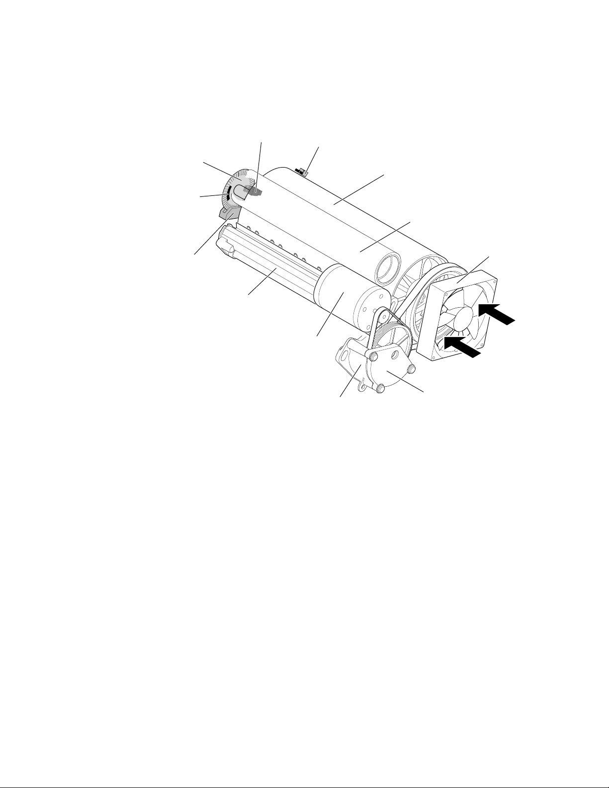
Theory of Operation
5
The drum is driven by a closed-loop servo motor which, through a double
reduction belt drive, rotates the drum at 190 rpm for imaging and a constant low
speed for image transfer to paper.
Encoder
disk
Home
flag
Encoder
Drum heater
Home sensor
Servo motor
Warning: Closed-loop
servo drive
Temperature
sensor (~49°C)
Drum
Transfer roller
Fan
Belt drive
9100-13
Figure 5-3 The drum/transfix assembly
Warning
Keep your fingers away from the drum drive system; it uses a
closed-loop drive system. A closed-loop servo drive system is
inherently dangerous. Since the motor speeds up if it senses the
drum drive system slowing down, fingers caught in the drum belts
and gears can be severely injured.
5-4
Phaser 340 Color Printer
Page 97
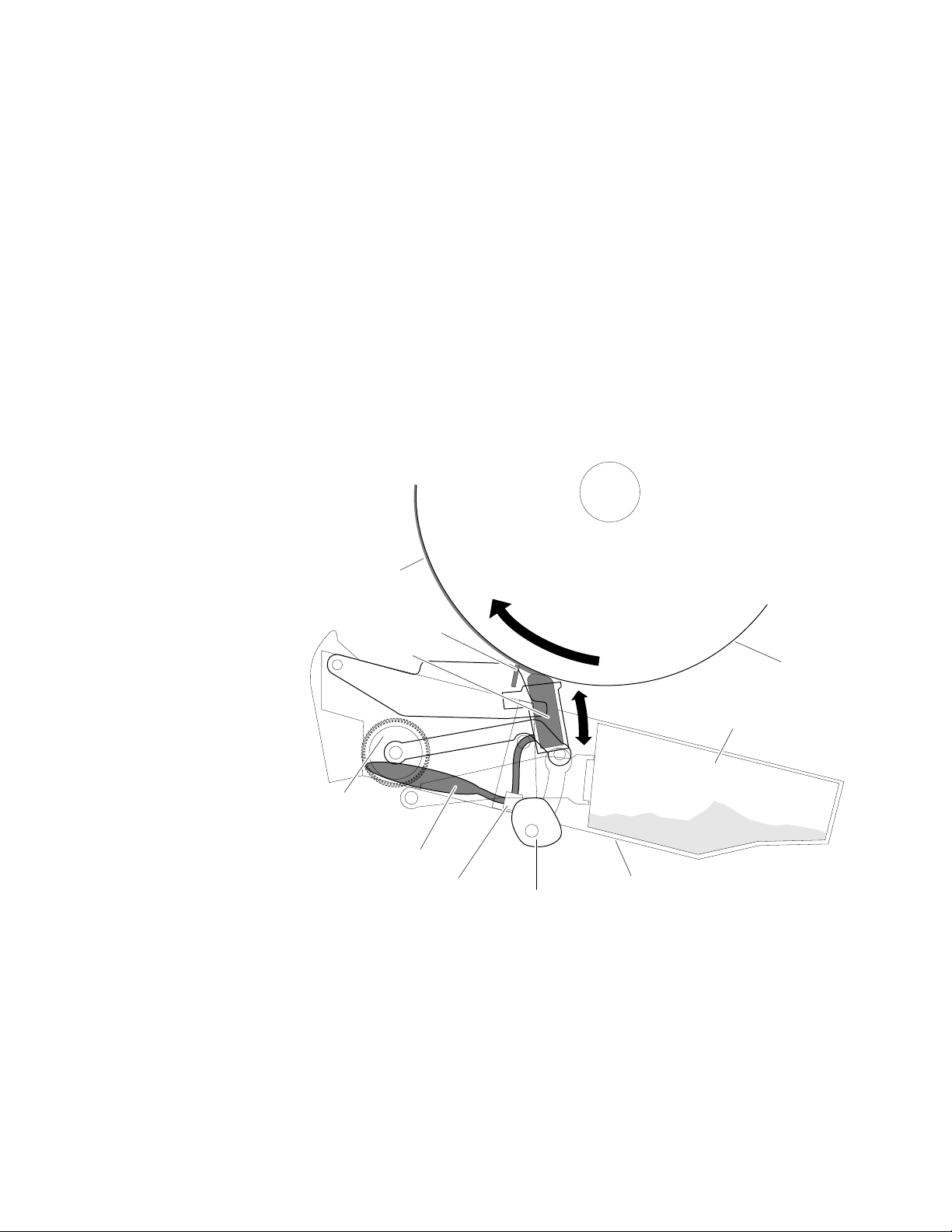
9100-15
Oil on drum
Blade
Wick
Drum
Maintenance cartridge
Waste ink bin
Oil valves
Oil bladder
Counter
gear
Cam
Maintenance tray
Theory of Operation
The maintenance tray performs two functions. It’s primary function is to apply
a thin coating of releasing agent, a silicon oil, 5 millionths of an inch thick to the
surface of the drum prior to printing. The releasing agent keeps the ink from
sticking to the drum’s surface and facilitates its transfer to the sheet of paper or
transparency film. The release agent is contained in a 100 cc bladder. Applying
the releasing agent is accomplished using an oil-saturated wick supplied by two
tubes from the bladder. Small valves keep the oil from leaking out of the bladder
when the maintenance tray is not in the printer. The drum maintenance
cartridge’s second function is to collect waste ink from printhead purges in a
waste bin.
Note
The oil valves are always open when the maintenance tray is installed
in the printer. The oil can leak out if the printer does not remain level.
5
Figure 5-4 The drum maintenance cartridge
Service Manual
5-5
Page 98

Theory of Operation
5
Prior to each print, a cam, driven by the process motor, raises the wick against
the slowly rotating drum. A compliant blade, also raised by the same cam,
assures that the oil film is smooth and even across the drum’s surface. As the
drum completes one rotation, the rotating cam lowers the wick and then a
moment later, lowers the blade.
A counter gear slowly and incrementally advances a sensor interrupt flag across
the width of the maintenance tray each time the cartridge is used. When it
interrupts its sensor, it indicates the maintenance cartridge must be replaced.
(Initial shipments of maintenance trays advance a fabric roll with notches cut in
the beginning and end of the roll to signal the print engine main board of the
presence of a new or consumed tray.) The sensors are mounted on the
maintenance tray guides on the inside of the printer frame.
5-6
Phaser 340 Color Printer
Page 99
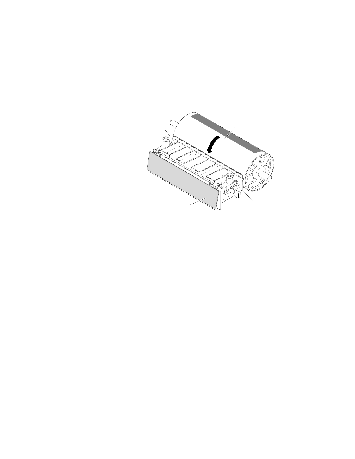
Printhead
Theory of Operation
The printhead is the heart of the printer. The printhead spans nearly the length
of the drum. Using its 352 ink-jet nozzles (88 jets for each primary color), with
just a horizontal motion of slightly less than 5 mm (0.2 inches), the printhead can
print the entire image on the rotating drum. The printhead produces two sized
drops of ink: a large drop for 300 dpi printing and a smaller drop for 600 dpi
printing.
Reservoir
Drum
5
Head drive board
Figure 5-5 The printhead
Jet stack
9100-16
The printhead’s jet stack is fabricated from a stack of chemically etched steel
plates which are brazed together to form the ink-jet array. Channels formed by
the stacked plates route ink past the 352 individual, piezoelectric crystal-driven
diaphragms, which force the ink in droplets out the 352 corresponding nozzles.
Looking at the printhead face, the nozzles are arranged in four rows with the
yellows nozzles forming the top row, the magenta nozzles forming the next row
24 pixels below, and the cyan row forming the third row 24 pixels below the
magenta row. The black nozzles are located 12 pixels below and 2 to the left of
the cyan nozzles. Each nozzle is separated horizontally by 28 pixels. (Pixel
spacing is at 300 pixels per inch.) During the printing process, the printhead
travels 28 pixels horizontally to provide complete coverage.
The ink-jet array is bonded to a cast aluminum ink reservoir. The reservoir
supplies the molten ink to the ink-jet array. Heaters in the reservoir and the
o
ink-jet array maintain the ink at a temperature of about 140
C for printing. The
level of the ink in the reservoir is kept at a constant level. The level is detected
by a sensor probe which senses the conductance of the ink at the probe tip.
Service Manual
5-7
Page 100
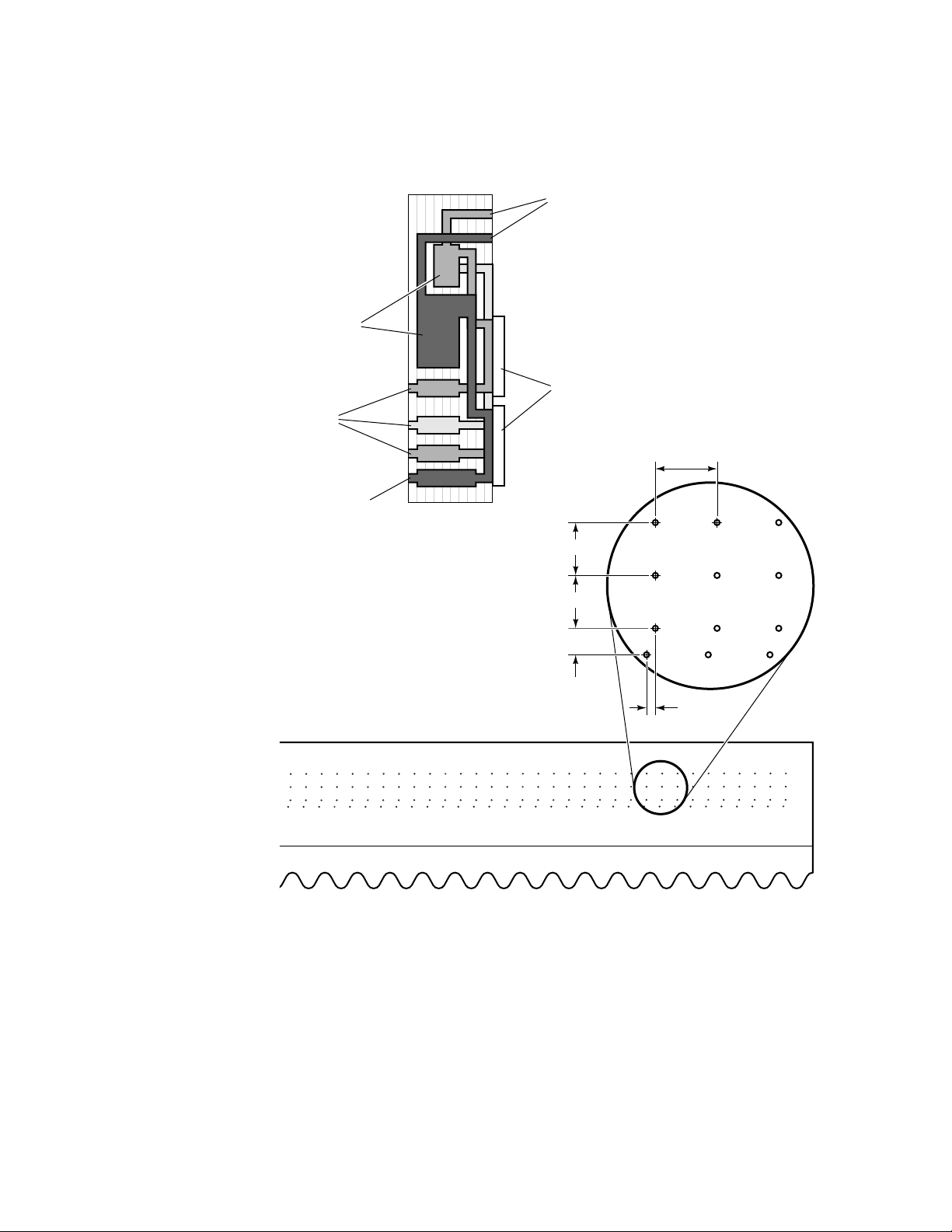
Theory of Operation
5
The illustration below shows a cross-section of the ink-jet array and the jet
nozzle arrangement.
Ink inlet
Manifolds
Piezoelectric crystals
Color
nozzles
Black nozzles
28 pixels
24 pixels
24 pixels
12 pixels
2 pixels
9100-17
5-8
Figure 5-6 The ink-jet array nozzle arrangement and cross-section
Phaser 340 Color Printer
 Loading...