

Page 1

Service Manual Addendum
Phaser
™
340 and Phaser
Color Printer
™
350
This addendum contains information for servicing Phaser 340 Color Printers
printers serial-numbered BCxxxxx and up and Phaser 350 Color Printers.
July 1996
070-9100-85
Service Manual
1
Page 2

2
Phaser 340 overview
The Phaser 340 Color Printer is an Adobe PostScript Level 2 color, solid ink-jet
printer with Tektronix color matching extensions (TekColor 3.0). The Phaser 340
is marketed in two variations: The Phaser 340 and the Phaser 340 Plus (also
called Phaser 340 with Extended Features). Externally and mechanically, the
Phaser 340 and Phaser 340 Plus are identical. The startup page indicates
whether the printer is a “Plus” model. Additionally, the Macintosh printer
driver indicates if the printer is a “Plus” model.
Note
The Phaser 340 prints at an addressability of 300 dots per inch (dpi) and features
17 built-in fonts and 8 Mbytes of RAM, which can be upgraded to 12 Mbytes.
The Phaser 340 Plus prints at an addressability of 600 x 300 dots-per-inch or
300 x 300 dpi, features 69 built-in fonts, and comes with 24 Mbytes of RAM. The
Phaser 340 Plus is also capable of job pipelining; it can print one image and
process the data for the next image at the same time.
Both printers feature two available paper trays: A and A4, with an optional
500-sheet high-capacity Lower Paper Tray Assembly which gives the printer a
dual-tray capability. (The Lower Paper Tray Assembly is sometimes referred to
as the second feeder; it only supports paper printing.) The printers print images
on A- and A4-size paper and transparency film with 5 mm (0.2 in.) margins; the
bottom margin is 7 mm (0.3 in). Each can print up to a rate of four pages per
minute; although the Phaser 340 Plus has greater image processing capabilities
for faster image throughput. Both variations feature a SCSI port to support an
external SCSI disk for additional font storage and the Phaser CopyStation copier
option.
Unless otherwise noted, descriptions and servicing are identical for
the Phaser 340 and the Phaser 340 Plus.
Early in 1996, Tektronix introduced a significantly redesigned
Phaser 340 and Phaser 340 Plus, denoted by the serial numbers
xxxx, BDx xxxx, BEx xxxx, B6E xxxx and B6F xxxx . These
BCx
printers are often referred to as Version 2 printers. Theses printer
feature some new FRU components that are not compatible with older
printers. These printers also have an updated front panel menu
structure with new menu items.
A 68K processor oversees print engine operations; the printer’s PostScript image
processor is powered by a 32-MHz 29K RISC processor. The printer features an
integral bi-directional parallel port. A rear panel slot allows customers to install
one “smart card” Phaser Share Network Card. One version card provides an
RS-232C serial port and a LocalTalk port. A second, alternative card offers an
Ethernet port which includes support for EtherTalk, Novell NetWare and
TCP/IP. A third card provides a Token Ring interface supporting Novel
NetWare, TokenTalk, and TCP/IP. TCP/IP protocol support is standard in
printers serial-numbered BCxx
supported via a downloaded software key in earlier printers (Version 1 printers).
Phaser 340 and 350 Color Printers
xxx and up. TCP/IP protocol is optionally
Page 3

Phaser 350 overview
The Phaser 350 Color Printer is a significant improvement over the Phaser 340.
Foremost among the Phaser 350 Color Printer’s features is its 6 page-per-minute
FastColor print mode. The print mode is selectable through the front panel and
from printer drivers. Other features are: The ability to set the printer’s IP
address easily from the front panel, a multi-page print collation mode (hard disk
required), and PrintCheck which lets you preview the first print of a muliple
copy job before letting the printjob continue. The front panel features the printer
name and status information similar to the Phaser 550.
The Phaser 350 prints at an addressability of 300 dots per inch (dpi) and features
17 built-in fonts and 8 Mbytes of RAM, which can be upgraded to 24 Mbytes.
The Phaser 350 with the Extended Featues option prints at an addressability of
600 x 300 dots-per-inch (Enhanced) or 300 x 300 dpi (Standard), features
69 built-in fonts, and comes with 24 Mbytes of RAM. The Phaser 350 with
Extended Features is also capable of job pipelining; it can print one image and
process the data for the next image at the same time.
Version 3.0 Ethernet and TokenRing cards add support for Telnet and ftp, and
PhaserLink allows users to monitor and control the printer via an internet
browser.
Print engine exchange
In extreme situations it may be necessary for service personnel to exhange the
entire print engine, while transferring the main board which maintains
purchased options and network identity at the customer’s printer.
The two printer modules for this exchange program are:
650-3260-00 supports Phaser 340s serial-numbered B1xxxxx through
■
B9xxxxx, except B6Exxxx and B6Fxxxx.
650-3184-01 supports Phaser 340s serial-numbered BCxxxxx through
■
BExxxxx and B6Exxxx and B6Fxxxx. It also supports all Phaser 350s.
The 650-3260-00 engine is a 2:1 jet interlace chassis; the 650-3184-01 is a 4:1 jet
interlace chassis shipped with two front panel logos so the proper one can be
installed.
Service Manual
3
Page 4

4
B4 zz
B5 zz
B6 zz
B7 zz
B8 zz
B9 zz
BC zz
Serial numbering for Phaser 350
The serial number has the format of B YRxxxx where:
■
B = Beaverton
Y = Year (0-9)
■
■
R = Revision level (A thru Z, minus “I” and “O”)
xxxx = numerical values only (0-9)
■
This is the begining serial number for the Phaser 350:
B6A0100
■
Serial number history for Phaser 340
■
B = Beaverton
Y = Year (0 - 9)
■
■
M = Month (0 - 9, A, B, C)
D = Day (base 34)
■
■
R = Revision level (range 0 thru 9 and A thru Z; base 34)
xxxx = numerical values only (0 - 9)
■
■
zz = alphanumerial values (range 0 - 9 and A through Z; base 34)
These are previous printer serial number patterns in sequential order:
■
B15 First production output, serial number format B RYMDzz .
B25 V1.2 print engine firmware.
■
■
B35 V1.8 print engine firmware.
■
Serial number format change, serial number format B RzzDMY .
■
■
■
■
■
■
V1.22 print engine firmware.
V1.24 print engine firmware, field update is 650-3163-02.
Power supply 650-3365-01 or 650-3397-00 thermistor kit.
Redesigned cap/wipe/purge assembly 650-3258-01.
2-flag ink loader.
Version 2 chassis, Web support and NDS support on Netware, 4:1
jet interlace.
Phaser 340 and 350 Color Printers
Page 5

BD zz
BE zz
■
■
pick).
■
B6E Serial number format change; serial number format BY Rxxxx .
B6F New main board, 671-3760-80 is exchange part number.
■
De-skew hardware installed (only 14 printers shipped).
Same as BCzz (de-skew removed, too noisy during paper
Accessing the printer’s web page
For printers serial-numbered BCxxxxx and up and the Phaser 350. PhaserLink,
the Tektronix implementation of a World Wide Web server inside the printer,
allows a customer to communicate to the printer using a web browser. With
PhaserLink, a customer can view and set printer and networking parameters. A
homepage built into the printer links the printer to other homepages such as the
Tektronix World Wide Web home page.
To view the printer’s homepage, the printer must be connected to a network
supporting TCP/IP protocols and be assigned an IP address. Refer to the
PhaserShare Network Cards and Software User Manual .
PC-based diagnostics
The PC-based diagnostics allows you to interactively test and check the
operations and functionality of the printer. The diagnostics are provided on a
3-1/2 inch floppy diskette. All of the diagnostic tests are started from the PC.
Some of the tests are stored on-board the main board in ROM and are merely
started by the PC-based diagnostics; other tests are downloaded to the printer
from the PC. The test are functionally divided into two classes: 29K tests, which
execute test stored in the 29K processor’s ROM and the 68K tests which are
downloaded to the printer to test the 68K processor and the print engine.
The PC diagnostics were developed to run on a PC. The diagnostics are used
with an Apple® PowerBook® running PC emulation software as this is the
portable computer in use by Tektronix Field Service.
Note
Printers serial-numbered B0xxxxx to BB xxxxx use diagnostics
version 1.24. Printers serial-numbered BCxxxxx and up use
diagnostics version 2.40. Both diagnostics are available on the same
diskette. Printers B0xxxxx to BBxxxxx may receive a firmware
upgrade, upgrade kit Z340PL, revising the firmware to 2.40R. The
“R” is visible only on the ROM’s label, not on the printer’s startpage.
These printers require version 2.40R or 2.40RA diagnostics.
A future release of the diagnostics is planned that will automatically
select the correct version when the diagnostics are started.
Service Manual
5
Page 6

6
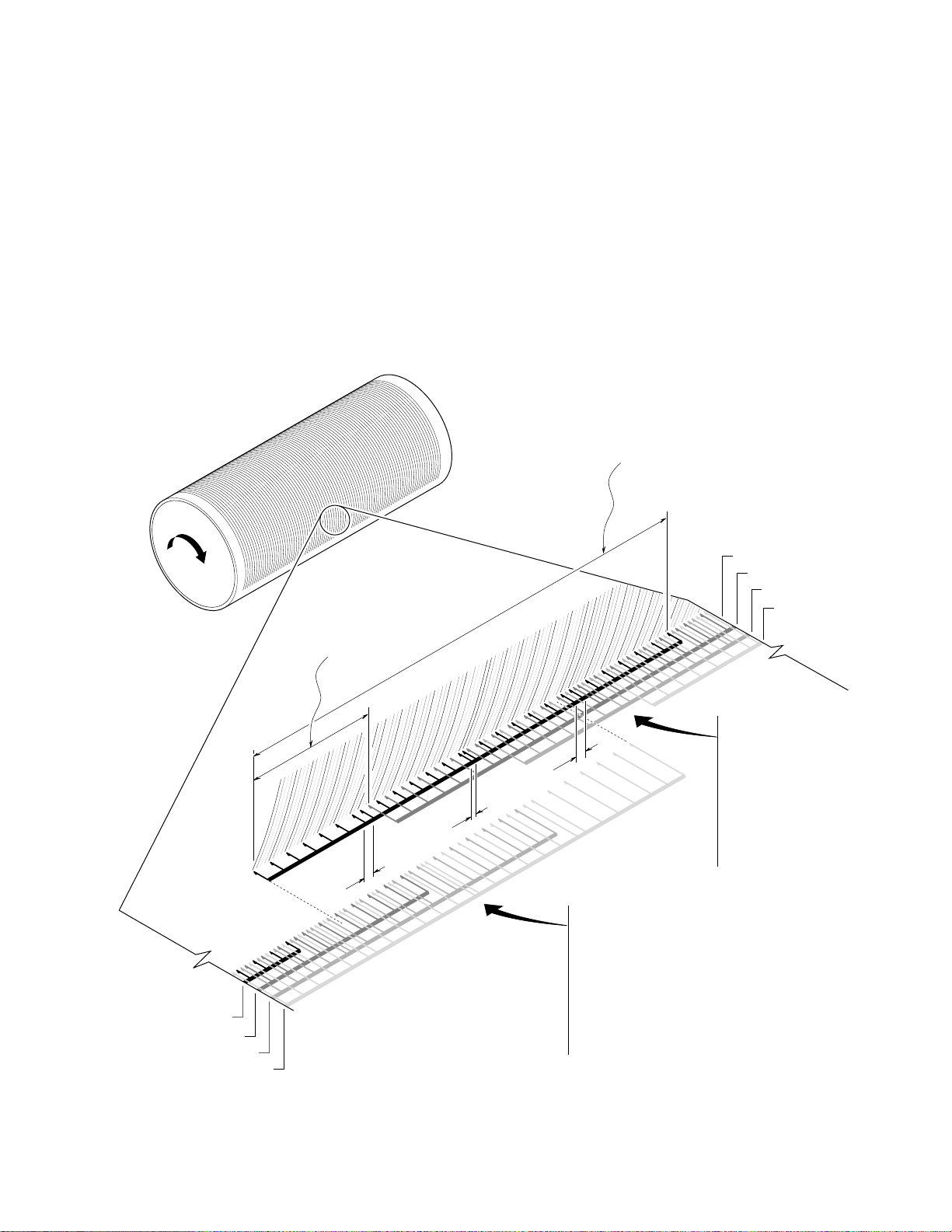
Jet interlacing
1.
2.
3.
4.
5.
6.
7.
Phaser 340 color printers serial numbered BC xxxxx and later and Phaser 350
printers use a different method of laying ink onto the drum; they perform a
“four-jet interlace.” As the drum reaches the correct speed of 176 rpm, the
ink-jets begin to fire to deposit the image on the oiled portion of the drum. As
the jets fire, the printhead slews in the x-axis to complete the image on the drum.
When the ink image is about 80% complete, the paper-pick cycle begins.
For 300 dpi printing, each jet lays down 28 pixel columns. Each jet lays down
one pixel column for each drum rotation (28 revolutions total). Each jet travels
horizontally the distance of 112 pixels to lay down its 28 pixel columns within
that 112 pixel-wide field. The 112 pixel-wide field of each jet overlaps the
112 pixel-wide field of six other jets; this is where interlacing occurs. To lay
down its 28 pixel columns, each jet follows this sequence:
Print 1st column, step four columns to the right, print 2nd column,
step four columns to the right. Repeat until 7 columns are laid down.
Step 2 additional columns to the right.
Print the 8th column, step 4 columns to the right, print 9th column,
step 4 columns to the right. Repeat until 7 columns are laid down
(total of 14 so far).
Step 1 additional column to the right.
Print the 15th column, step 4 columns to the right, print the 16th
column, step 4 columns to the right. Repeat until another 7 columns
are laid down (21 total so far).
Step 2 additional columns to the right.
Print the 22nd column, step 4 columns to the right, print the 23rd
column, step 4 columns to the right. Repeat until the last 7 columns
are laid down for a total of 28 pixel columns.
The intermediate 2-step, 1-step and 2-step movement between the 7th and 8th
pixel columns, the 14th and 15th columns, and the 21st and 22nd columns,
respectively, allow the 28 pixels columns of each jet to properly interlace with
the 28 pixel columns of the other jets it is combined with. A total of
2,432 columns, each 3,134 dots tall, are laid down.
The advantage of this print method is that variability between jets is “averaged
out” by being interlaced with three other jets. As shown in the illustration, of the
28 pixel columns printed by any single jet, only two of its pixel columns are
actually ever adjacent. Usually they are separated by three other pixel columns
produced by other jets, hence the name
spacing between jets and the 112 pixel-wide field that each jet travels, the pixel
columns of any one jet actually interlaces with the pixel columns of six other jets,
although no more than four at any one time.
four-jet interlace . Because of the 28 pixel
In reality, because of the fixed width of the printhead and inter-jet spacing, the
outermost jets cannot interlace completely with their adjacent jets. In this case,
the drum rotates for seven extra imaging rotations (14 if both end jets are
needed) for the printhead to reposition the end jets so they can fill-in the missing
pixel columns that cannot otherwise be interlaced.
Phaser 340 and 350 Color Printers
Page 7
7
For transparency printing, the image is printed in the same manner. However,
the image is printed, with smaller droplets, twice on the drum, the second image
positioned precisely over the first image before being transferred to the sheet of
transparency film; this increases image density.
For 600 x 300 dpi printing, each jet lays down 56 columns of ink drops spread
over a 224 pixel-wide field. The drum rotates 56 times to receive the pixel
columns. The same interlace method is used, except 14 pixel columns are
printed between the intermediate 2-step, 1-step and 2-step movements. A total
of 4,864 columns, each 3,134 dots tall, are laid down. The x-axis motor steps at
half the rate to double the resolution in the x-axis. Also, the printhead jets
output smaller, 600 dpi dots.
112 pixel-wide
field traveled by a jet
1 of 4
2 of 4
3 of 4
4 of 4
28 pixel
separation
between jets
2 Step
1 Step
2 Step
Output of four
side-by-side jets
1 of 4
2 of 4
3 of 4
4 of 4
Column of pixel dots
produced by four
adjacent jets are
interlaced together
for 300 dpi printing.
Each jet produces
28 pixel columns.
For 600 dpi printing,
each jet produces
56 pixel columns.
Columns of pixel
dots produced by
previous set of four
adjacent jets. Note
how the ending
columns of this set
interlace with
beginning columns
of the next set of
four jets.
9100-107
Service Manual
Page 8

8
Enabling TCP/IP with the authorization code
.
1.
2.
3.
1.
2.
3.
TCP/IP protocol support is standard in Phaser 340 printers serial-numbered
xxx and up and Phaser 350 printers. This feature depends upon the version
BCxx
of firmware on the PhaserShare card being 2.0 or higher. TCP/IP protocol is
optionally supported via a downloaded software key in earlier printers.
When the Phaser Share Ethernet card is installed, the EtherTalk and Novell
protocols are immediately active. For printer’s serial numbered B1xxxxx
through B9xxxxx, the Ethernet card’s TCP/IP protocol must be activated by a
downloadable authorization code, sometimes referred to as its software key.
The authorization code is printed on a certificate included with the printer (if the
option was factory-installed) or with the field upgrade kit. The
Manual and Phaser Share Network User Manual
authorization code and download it to the printer
two-step process: It consists of editng a file called “authorize.ps” that contains
the authorization code and then downloading the file to the printer using a file
downloading utility such as Font Downloader or LaserWriter Utility.
explain how to activate the
Downloading the code is a
Phaser Share User
Bypass mode
Bypass mode allows you to access the front panel menus (bypassing the engine
and PostScript initializing processes) without having to wait for the printhead to
warm up. This way, you can reset NVRAM or read fault codes immediately.
Meanwhile, the printer continues to warm-up and initialize “in the
background.” Even if the engine faults, bypass mode can be active.
Press and hold front panel buttons 1 and 2 (left two buttons). Turn on
the printer.
Wait for the message Entering Bypass Mode to be displayed
(about 40 seconds).
Release buttons 1 and 2. For the Phaser 350, do not press buttons 1
and 2 until the first “Warming Up” message is displayed, then quickly
press the buttons and hold for a few seconds until “Entering Bypass
Mode” is displayed.
Cool down mode
Phaser 340 printers serial-numbered BCxxxxx and up and Phaser 350 printers
have a menu item that accelerates the cooling of the printhead.
Enter the extended menu by pressing Menu and Exit .
Scroll to the Service Suppor t menu item and press Menu.
Scroll to the item Cool-down for Power Off and press OK .
The printer turn off all the engine heaters and runs the fans on high until the ink
in the printhead has solidified. Then the printer’s front panel informs you the
printer can be turned off.
Phaser 340 and 350 Color Printers
Page 9

Error codes and messages
Error codes indicate the following:
■
the failing system ( XX ,yyy.zz)
the failing subsystem (xx, YYY .zz)
■
■
the actual problem (xx,yyy.ZZ).
■ the print engine copy count (xx,yyy.zz:123) the error occurred on.
Codes from 24,000 through 24,999 are engine failures reported by the PostScript
controller. They are not stored in the fault history table of the NVRAM. They
are reported when the engine has been stuck in a state for 25 minutes.
Front panel and fault history log error codes and messages
Error code Meaning
4,000: PC (process control supervisor)....
4,001.40 (0x2401):
PC_DEV_FAULT_HEAD_READ
4,002.41 (0x2402):
PC_DEV_FAULT_HEAD_ZEROS
4,003.42 (0x2403):
PC_DEV_FAULT_HEAD_ONES
4,004.43 (0x2404):
PC_DEV_FAULT_HEAD_CHECK
SUM
4,005.44 (0x2405):
PC_DEV_FAULT_DM_
CAM_ERR
4,006.45 (0x2406):
PC_DEV_FAULT_300DPI_CAL
4,007.46 (0x2407):
PC_DEV_FAULT_600DPI_CAL:
4,008.47 (0x2408)
PC_DEV_FAULT_STUCK_DMC:
4,009.48 (0x2409)
PC_DEV_FAULT_DM_
CAM_BEGIN
Failure reading printhead NVRAM data: check the wiring to the
printhead, I
Printhead NVRAM data was all zeros: has this printhead been through
normalization? If so, check wiring to printhead.
Printhead NVRAM data was all ones: has this printhead been through
normalization? If so, check the wiring to the printhead.
Printhead NVRAM checksum failure: the data within the printhead
NVRAM has been corrupted. Check the the printhead ribbon cable and
associated connections.
Failure positioning drum maintenance cam during a drum maintenance
cycle: check drum maintenance cam solenoid, clutch, home sensor, and
related hardware.
Calibration failure: Target Volt-Sec Area of 300 dpi could not be
achieved. “Head Adjust” head drive voltage may be incorrectly set.
Possible hardware failure on printhead.
Calibration Failure: Target Volt-Sec Area of 600 dpi could not be
achieved. “Head Adjust” head drive voltage may be incorrectly set.
Possible hardware failure on printhead.
Failure to advance the drum maintenance tray sensor interrupt flag. It
has been in the new tray state for too long. Check the hardware.
At the start of a drum maintenance cycle, when the drum maintenance
cam position should have been at blade down, wick down, the drum
maintenance cam home sensor should have been TRUE and was
instead FALSE. Check the drum maintenance cam solenoid, clutch,
home sensor, and related hardware.
2
C bus and other hardware.
4,010.40 (0x240A)
PC_DEV_FAULT_DM_CAM_BU_
WU
During the drum maintenance cycle, when the drum maintenance cam
position should have been at blade up/wick up, the drum maintenance
cam home sensor should have been FALSE and was instead TRUE.
Check the drum maintenance cam solenoid, clutch, home sensor, and
related hardware.
Service Manual
9
Page 10

Front panel and fault history log error codes and messages (cont'd.)
Error code Meaning
4,011.41 (0x240B)
PC_DEV_FAULT_DM_
CAM_BU_WD
4,012.42 (0x240C)
PC_DEV_FAULT_DM_
CAM_END
4,013.43 (0x240D)
PC_DEV_FAULT_GEAR_GRIND
4,015.45 (0x240F)
PC_DEV_FAULT_HEAD_
ADJUST_TIMEOUT
4,016.46 (0x2410)
PC_DEV_FAULT_HEAD_NV_
FORMAT
4,017.47 (0x2411)
PC_DEV_FAULT_AMBIENT_
TOO_COLD
During the drum maintenance cycle, when the drum maintenance cam
position should have been at blade up/wic k down, the drum maintenance
cam home sensor should have been FALSE and was instead TRUE.
Check the drum maintenance cam solenoid, clutch, home sensor, and
related hardware.
At the end of a drum maintenance cycle, when the drum maintenance
cam position should have been at blade down/wick down, the drum
maintenance cam home sensor should have been TRUE and was
instead FALSE. Check the drum maintenance cam solenoid, clutch,
home sensor, and related hardware.
During power-on initialization, the engine is unable to disengage the
process motor. Prior to declaring this fault, the engine has attempted to
move the process motor through enough revolutions to disengage the
head tilt mechanism, but the motor stalled. The X axis was then
displaced to the right 0.15 inches and the disengage was repeated, but
the motor stalled again. This fault is then declared. The head is unable
to move on its tilt axis, perhaps because it is colliding with something
(head restraint pin, cap, poorly installed ink loader, screwdriver.)
The engine spent too much time in printhead adjust state. The engine
declares a device fault and shuts down, rather than leave a hot heater
against a cold drum for an indefinite period
The printhead format number, stored in printhead NVRAM, is not
understood by this version of engine firmware.
Ambient temperature has fallen to less than 10
wrong with a heater.
o
C. Something may be
4,018.48 (0x2412)
PC_DEV_FAULT_LATE_CLEAN_
REQUEST
4,019.40 (0x2413) :
PC_DEV_FAULT_193DPI_CAL
5,000: Y axis (drum)
5,001.41 (0x2c01):
YA_HOME_FAIL
5,002.41 (0x2b02):
YA_STALL_FAIL
5,002.42 (0x2b03): YA_POS_FAIL Y-axis position failure, the drum is not where is should be, possibly
5,002.41 (0x2b02):
YA_STALL_FAIL
5,003.42 (0x2b03): YA_POS_FAIL Y axis position failure: the drum is not where it should be. Besides the
After the printer determined, at power up, that the printhead was warm
enough not to need cleaning, and while the printer was warming up the
printhead temperature dropped below the head-clean-needed threshold.
Something may be wrong with a heater.
Calibration Failure: Target Volt-Sec Area of Fast Color mode could not be
achieved. “Head Adjust” head drive voltage may be incorrectly set.
Possible hardware failure on printhead.
Drum home sensor failure: the drum turned one full revolution without
seeing the drum home sensor activate. Check the drum home sensor.
The Y-axis (drum) motor stalled, possibly because the drum position
sensor electronics have failed, or because the motor drive or drive belts
have failed, or because something is physically blocking the motion of
the drum.
because the drum position sensor electronics have failed, or because the
motor drive or drive belts have failed, or because something is physically
blocking the motion of the drum
The drum stalled: the drum stalled because the motor drive or drive
belts have f ailed, or because something is ph ysically b loc king the motion
of the drum.
possible mechanical problems, this can be caused by software latency
errors, if too many interrupts occur during drum positioning.
10
Phaser 340 and 350 Color Printers
Page 11

Front panel and fault history log error codes and messages (cont'd.)
Error code Meaning
6,000: X axis
6,000.41 (0x3400):
XA_FAULT_MCURRENT
6,001.42 (0x3401):
XA_FAULT_NOHOME
6,002.43 (0x3402):
XA_FAULT_NGHOME
6,003.44 (0x3403):
XA_FAULT_LOST
7,000: Process motor
7,001.43 (0x3c01):
PM_FAULT_AUXILIARY_
MOTOR_ERROR
7,002.44 (0x3c02):
PM_FAULT_PROCESS_MOTOR_
STALL
7,003.45 (0x3c03):
PM_FAULT_ COMPOUND_
GEAR_SENSOR_BAD
7,004.46 (0x3c04):
PM_FAULT_DM_CAM_
SENSOR_BAD
X axis motor over/under current. Indicates that motor coil(s) are open, or
shorted, or the x-axis motor fuse has opened.
X-axis home position not found. Indicates that the x-axis home sensor
has failed, or something has prevented the printhead motion during a
home operation.
Unexpected x-axis home sensor activation. The sensor has failed, the
motor control is moving the printhead in the wrong direction, or the user
has engaged the printhead restraint mechanism.
A verify of the home calibration failed. After locating the home sensor
transition, the DMC computed x-axis position varied from the home value
by more than the acceptable tolerance.
The electronics report an error while operating the motor in the auxiliary
feeder (the optional lower tray)
The process motor stalled during operation. This has several possible
causes, depending on what the process motor was gear-connected to at
the time of failure.
No transitions are observed of the compound gear sensor when the
compound gear should be turning. Perhaps the sensor is bad, or the
process motor to compound gear linkage is broken.
No transitions are observed of the drum maintenance cam sensor. The
sensor may be bad or the drum maintenance cam may be jammed.
7,005.47:
PM_FAULT_PREHEAT_EXIT_
SENSOR_BAD ().
8,000: Cap drive and web sensors
8,001.44 (0x4401):
CAP_FAULT_HOME_
SENSOR
8,002.45 (0x4402):
CAP_FAULT_WEB_
SENSORS
8,003.46 (0x4403): CAP_FAULT_
OVERCURRENT
9,000: Ink loader: ink melters and printhead ink level sensors.
9,001.45 (0x4c01): IL_FAULT_C_
TWANGER
9,002.46 (0x4c02): IL_FAULT_M_
TWANGER
9,003.47 (0x4c03): IL_FAULT_Y_
TWANGER
9,004.48 (0x4c04): IL_FAULT_K_
TWANGER
The preheater exit sensor is not being detected, it is either unplugged or
defective.
An expected transition of the cap home sensor did not occur. The home
sensor may be faulty, or the cap motor may not be operating, or the cap
may be jammed and unable to move.
A fault is detected in the web sensors. Check the left and right
maintenance tray sensors and their wiring harness.
The cap/wipe/purge assembly stalled. (This f ault does not actually occur
because the mechanism is loose. When the assembly jams, the motor
skips over teeth.)
Malfunction of the ink level sensor in the cyan reservoir. Replace the
printhead.
Malfunction of the ink level sensor in the magenta reservoir . Replace the
printhead.
Malfunction of the ink level sensor in the yellow reservoir. Replace the
printhead.
Malfunction of the ink level sensor in the black reservoir. Replace the
printhead.
Service Manual
11
Page 12

Front panel and fault history log error codes and messages (cont'd.)
Error code Meaning
9,005.40 (0x4c05):
IL_FAULT_C_JAM
9,006.41 (0x4c06):
IL_FAULT_M_JAM
9,007.42 (0x4c07):
IL_FAULT_Y_JAM
9,008.43 (0x4c08):
IL_FAULT_K_JAM
13,000:printhead thermals
13,001.40 (0x6c01):
TCH_JS_LEFT_OPEN
13,002.41 (0x6c02):
TCH_JS_LEFT_SHORT
13,003.42 (0x6c03):
TCH_JS_LEFT_HOT
13,004.43 (0x6c04):
TCH_JS_LEFT_SLOW
13,017.47 (0x6c11):
TCH_JS_RIGHT_OPEN
13,018.48 (0x6c12):
TCH_JS_RIGHT_SHORT
The cyan ink melt heater is on, but ink does not seem to be dripping.
Check that the ink stick is able to advance in the chute.
The magenta ink melt heater is on, but ink does not seem to be dripping.
Check that the ink stick is able to advance in the chute.
The yellow ink melt heater is on, but ink does not seem to be dripping.
Check that the ink stick is able to advance in the chute.
The black ink melt heater is on, but ink does not seem to be dripping.
Check that the ink stick is able to advance in the chute.
The thermistor in the left jetstack appears to be open. Replace the
printhead ribbon cable. Check connections. Peplace the printhead.
The thermistor in the left jetstack appears to be shorted. Replace the
printhead.
The left jetstack heater is running away. Unplug the printer NOW!
The left jetstack heater is not heating at all, or is not heating as quickly as
it should. Replace the printhead ribbon cable. Check connections.
Peplace the printhead.
The thermistor in the right jetstack appears to be open. Replace the
printhead ribbon cable. Check connections. Peplace the printhead.
The thermistor in the right jetstack appears to be shorted. Replace the
printhead.
13,019.40 (0x6c13):
TCH_JS_RIGHT_HOT
13,020.41 (0x6c14):
TCH_JS_RIGHT_SLOW
13,033.45 (0x6c21):
TCH_RESERVOIR_OPEN
13,034.46 (0x6c22):
TCH_RESERVOIR_SHORT
13,035.47 (0x6c23):
TCH_RESERVOIR_HOT
13,036.48 (0x6c24):
TCH_RESERVOIR_SLOW
14,000: Cap thermals
14,001.41 (0x7401):
TCC_THERMISTOR_OPEN
14,002.42 (0x7402):
TCC_THERMISTOR_SHORT
14,003.43 (0x7403):
TCC_THERMISTOR_HOT
14,004.44 (0x7404):
TCC_THERMISTOR_SLOW
The right jetstack heater is running away. Unplug the printer NOW!
The right jetstack heater is not heating at all, or is not heating as quickly
as it should. Replace the ribbon cab le. Check connections. Peplace the
printhead.
The thermistor in the reservoir appears to be open. Replace the
printhead ribbon cable. Check connections. Peplace the printhead.
The thermistor in the reservoir appears to be shorted. Replace the
printhead.
The reservoir heater is running away. Unplug the printer NOW!
The reservoir heater is not heating at all, or is not heating as quickly as it
should. Replace the ribbon cable. Check connections. Peplace the
printhead.
The cap/wipe/purge assembly thermistor appears to be open. Replace
the assembly.
The cap/wipe/purge assembly thermistor appears to be shorted.
Replace the assembly.
The cap/wipe/purge assembly heater is running away. Unplug the printer
NOW! Possible swapped sensor cable connectors on I/O #2.
The cap/wipe/purge assembly heater is not heating at all, or is not
heating as quickly as it should. Check for open connection or open
thermistor in power supply.
12
Phaser 340 and 350 Color Printers
Page 13

Front panel and fault history log error codes and messages (cont'd.)
Error code Meaning
14,005.45:TCC_WRONG_
TYPE_CAP
15,000: Drum thermals
15,001.42 (0x7c01):
TCD_THERMISTOR_OPEN
15,002.43 (0x7c02):
TCD_THERMISTOR_SHORT
15,003.44 (0x7c03):
TCD_THERMISTOR_HOT
15,004.45 (0x7c04):
TCD_THERMISTOR_SLOW
16,000: Preheater thermals
16,001.43 (0x8401):
TCP_THERMISTOR_OPEN
16,002.44 (0x8402):
TCP_THERMISTOR_SHORT
16,003.45 (0x8403):
TCP_THERMISTOR_HOT
16,004.46 (0x8404):
TCP_THERMISTOR_SLOW
22,000: Media jams
The installed cap/wipe/purge assembly is the wrong type for this printer.
Verify and install the correct assembly or firmware for this printer.
The drum thermistor appears to be open. Replace the drum temperature
sensor.
The drum thermistor appears to be shorted. Replace the drum
temperature sensor.
The drum heater is running away. Unplug the printer NOW! Possible
swapped power cable with the preheater. Possible swapped sensor
cable at I/O #2.
The drum heater is not heating at all, or is not heating as quickly as it
should. Check for open connection or open thermistor in power supply.
The preheater thermistor appears to be open. Replace the paper
preheater.
The preheater thermistor appears to be shorted. Replace the paper
preheater.
The preheater heater is running away. Unplug the printer NOW!
Possible swapped power cable with the drum heater.
The preheater heater is not heating at all, or is not heating as quickly as
it should. Chec k for open connection or open thermistor in power supply.
22,000.37 Jam -- Media at standard tray, unexpected event standard tray ajar 1.
22,001.38 Jam -- Media at standard tray, unexpected event standard tray A4-size
22,002.30 Jam -- Media at standard tray, unexpected event standard tray not used.
22,003.31 Jam -- Media at standard tray, unexpected event standard tray ajar 2.
22,004.32 Jam -- Media at standard tray, unexpected event standard tray A-size
22,005.33 Jam -- Media at standard tray, unexpected event standard tray A4-size
22,006.34 Jam -- Media at standard tray, unexpected event standard tray A-size
22,007.35 Jam -- Media at standard tray, unexpected event standard tray not
22,008.36 Jam -- Media at standard tray, unexpected event paper pick sensor
22,009.37 Jam -- Media at standard tray, unexpected event paper pick sensor
22,010.38 Jam -- Media at standard tray, unexpected event paper A-width sensor
22,011.30 Jam -- Media at standard tray, unexpected event paper A-width sensor
transparency.
transparency.
paper.
paper.
present.
TRUE.
FALSE.
FALSE, A4-width sensor FALSE.
TRUE, A4-width sensor FALSE.
22,012.31 Jam -- Media at standard tray, unexpected event paper A-width sensor
FALSE, A4-width sensor TRUE.
Service Manual
13
Page 14

Front panel and fault history log error codes and messages (cont'd.)
Error code Meaning
22,013.32 Jam -- Media at standard tray, unexpected event paper A-width sensor
22,014.33 Jam -- Media at standard tray, unexpected event paper preheat entry
22,015.34 Jam -- Media at standard tray, unexpected event paper preheat entry
22,016.35 Jam -- Media at standard tray, unexpected event paper preheat exit
22,017.36 Jam -- Media at standard tray, unexpected event paper preheat exit
22,018.37 Jam -- Media at standard tray, unexpected event paper exit sensor
22,019.38 Jam -- Media at standard tray, unexpected event paper exit sensor
22,020.30 Jam -- Media at standard tray, une xpected e vent paper hand-f eed sensor
22,021.31 Jam -- Media at standard tray, une xpected e vent paper hand-f eed sensor
22,022.32 Jam -- Media at standard tray, unexpected event auxiliary tray not
22,023.33 Jam -- Media at standard tray, unexpected event auxiliary tray A-size.
22,024.34 Jam -- Media at standard tray, unexpected event auxiliary tray A4-size.
TRUE, A4-width sensor TRUE.
sensor TRUE.
sensor FALSE.
sensor TRUE.
sensor FALSE.
TRUE.
FALSE.
TRUE.
F ALSE.
present.
22,032.33 Jam -- Media at auxiliary tray, unexpected event standard tray ajar 1.
22,033.34 Jam -- Media at auxiliary tray, unexpected event standard tray A4-size
22,034.35 Jam -- Media at auxiliary tray, unexpected event standard tray not used.
22,035.36 Jam -- Media at auxiliary tray, unexpected event standard tray ajar 2.
22,036.37 Jam -- Media at auxiliary tray, unexpected event standard tray A-size
22,037.38 Jam -- Media at auxiliary tray, unexpected event standard tray A4-size
22,038.30 Jam -- Media at auxiliary tray, unexpected event standard tray A-size
22,039.31 Jam -- Media at auxiliary tray, unexpected event standard tray not
22,040.32 Jam -- Media at auxiliary tray, unexpected event paper pick sensor
22,041.33 Jam -- Media at auxiliary tray, unexpected event paper pick sensor
22,042.34 Jam -- Media at auxiliary tray, unexpected event paper A-width sensor
22,043.35 Jam -- Media at auxiliary tray, unexpected event paper A-width sensor
transparency.
transparency.
paper.
paper
present.
TRUE.
FALSE.
FALSE, A4-width sensor FALSE.
TRUE,A4-width sensor FALSE
14
Phaser 340 and 350 Color Printers
Page 15

Front panel and fault history log error codes and messages (cont'd.)
Error code Meaning
22,044.36 Jam -- Media at auxiliary tray, unexpected event paper A-width sensor
22,045.37 Jam -- Media at auxiliary tray, unexpected event paper A-width sensor
22,046.38 Jam -- Media at auxiliary tray, unexpected event paper preheat entry
22,047.30 Jam -- Media at auxiliary tray, unexpected event paper preheat entry
22,048.31 Jam -- Media at auxiliary tray, unexpected event paper preheat exit
22,049.32 Jam -- Media at auxiliary tray, unexpected event paper preheat exit
22,050.33 Jam -- Media at auxiliary tray, unexpected e vent paper exit sensor TRUE.
22,051.34 Jam -- Media at auxiliary tray, unexpected event paper exit sensor
22,052.35 Jam -- Media at auxiliary tray, unexpected e vent paper hand-feed sensor
22,053.36 Jam -- Media at auxiliary tray, unexpected e vent paper hand-feed sensor
22,054.37 Jam -- Media at auxiliary tray, unexpected event auxiliary tray not
22,055.38 Jam -- Media at auxiliary tray, unexpected event auxiliary tray A-size
FALSE, A4-width sensor TRUE
TRUE, A4-width sensor TRUE
sensor TRUE
sensor FALSE
sensor TRUE.
sensor FALSE.
FALSE.
TRUE.
F ALSE.
present.
22,056.30 Jam -- Media at auxiliary tray, unexpected event auxiliary tray A4-size.
22,064.38 Jam -- Media at front cover, unexpected event standard tray ajar 1.
22,065.30 Jam -- Media at front cover, unexpected event standard tray A4-size
22,066.31 Jam -- Media at front cover, unexpected event standard tray not used.
22,067.32 Jam -- Media at front cover, unexpected event standard tray ajar 2.
22,068.33 Jam -- Media at front cover, unexpected event standard tray A-size
22,069.34 Jam -- Media at front cover, unexpected event standard tray A4-size
22,070.35 Jam -- Media at front cover, unexpected event standard tray A-size
22,071.36 Jam -- Media at front cover, unexpected event standard tray not present
22,072.37 Jam -- Media at front cover, unexpected event paper pick sensor TRUE.
22,073.38 Jam -- Media at front cover, unexpected event paper pick sensor FALSE.
22,074.30 Jam -- Media at front cover, unexpected event paper A-width sensor
22,075.31 Jam -- Media at front cover, unexpected event paper A-width sensor
22,076.32 Jam -- Media at front cover, unexpected event paper A-width sensor
transparency.
transparency.
paper.
paper.
FALSE, A4-width sensor FALSE.
TRUE, A4-width sensor FALSE.
FALSE, A4-width sensor TRUE.
Service Manual
15
Page 16

Front panel and fault history log error codes and messages (cont'd.)
Error code Meaning
22,077.33 Jam -- Media at front cover, unexpected event paper A-width sensor
22,078.34 Jam -- Media at front cover, unexpected event paper preheat entry
22,079.35 Jam -- Media at front cover, unexpected event paper preheat entry
22,080.36 Jam -- Media at front cover, unexpected event paper preheat exit sensor
22,081.37 Jam -- Media at front cover, unexpected event paper preheat exit sensor
22,082.38 Jam -- Media at front cover, unexpected event paper exit sensor TRUE.
22,083.30 Jam -- Media at front cover, unexpected event paper exit sensor FALSE.
22,084.31 Jam -- Media at front cover, unexpected event paper hand-feed sensor
22,085.32 Jam -- Media at front cover, unexpected event paper hand-feed sensor
22,086.33 Jam -- Media at front cover, unexpected event auxiliary tray not present.
22,087.34 Jam -- Media at front cover, unexpected event auxiliary tray A-size.
22,088.35 Jam -- Media at front cover, unexpected event auxiliary tray A4-size.
22,096.34 Jam -- Media at exit cover, unexpected event standard tray ajar 1.
TRUE, A4-width sensor TRUE.
sensor TRUE.
sensor FALSE.
TRUE.
FALSE.
TRUE.
FALSE.
22,097.35 Jam -- Media at exit cover, unexpected event standard tray A4-size
22,098.36 Jam -- Media at exit cover, unexpected event standard tray not used.
22,099.37, Jam -- Media at exit cover, unexpected event standard tray ajar 2.
22,100.38, Jam -- Media at exit cover, unexpected event standard tray A-size
22,101.30, Jam -- Media at exit cover, unexpected event standard tray A4-size
22,102.31, Jam -- Media at exit cover, unexpected event standard tray A-size paper.
22,103.32 Jam -- Media at exit cover, unexpected event standard tray not present.
22,104.33 Jam -- Media at exit cover, unexpected event paper pick sensor TRUE.
22,105.34 Jam -- Media at exit cover, unexpected event paper pick sensor FALSE.
22,106.35 Jam -- Media at exit cover, unexpected event paper A-width sensor
22,107.36 Jam -- Media at exit cover, unexpected event paper A-width sensor
22,108.37 Jam -- Media at exit cover, unexpected event paper A-width sensor
22,109.38 Jam -- Media at exit cover, unexpected event paper A-width sensor
transparency.
transparency.
paper.
FALSE, A4-width sensor FALSE.
TRUE, A4-width sensor FALSE.
FALSE, A4-width sensor TRUE.
TRUE, A4-width sensor TRUE.
16
22,110.30, Jam -- Media at exit cov er, unexpected ev ent paper preheat entry sensor
TRUE.
Phaser 340 and 350 Color Printers
Page 17

Front panel and fault history log error codes and messages (cont'd.)
Error code Meaning
22,111.31 Jam -- Media at exit cov er, unexpected ev ent paper preheat entry sensor
22,112.32 Jam -- Media at exit cover, unexpected event paper preheat exit sensor
22,113.33 Jam -- Media at exit cover, unexpected event paper preheat exit sensor
22,114.34 Jam -- Media at exit cover, unexpected event paper exit sensor TRUE.
22,115.35 Jam -- Media at exit cover, unexpected event paper exit sensor FALSE.
22,116.36 Jam -- Media at exit cover, unexpected event paper hand-feed sensor
22,117.37 Jam -- Media at exit cover, unexpected event paper hand-feed sensor
22,118.38 Jam -- Media at exit cover, unexpected event auxiliary tray not present.
22,119.30 Jam -- Media at exit cover, unexpected event auxiliary tray A-size.
22,120.31 Jam -- Media at exit cover, unexpected event auxiliary tray A4-size.
22,128.30 Jam -- Media at exit tray, unexpected event standard tray ajar 1.
22,129.31 Jam -- Media at exit tray, unexpected event standard tray A4-size
22,130.32 Jam -- Media at exit tray, unexpected event standard tray not used.
22,131.33 Jam -- Media at exit tray, unexpected event standard tray ajar 2.
F ALSE.
TRUE.
FALSE.
TRUE.
FALSE.
transparency.
22,132.34 Jam -- Media at exit tray, unexpected event standard tray A-size
22,133.35 Jam -- Media at exit tray, unexpected event standard tray A4-size paper.
22,134.36 Jam -- Media at exit tray, unexpected event standard tray A-size paper.
22,135.37 Jam -- Media at exit tray, unexpected event standard tray not present.
22,136.38 Jam -- Media at exit tray, unexpected event paper pick sensor TRUE.
22,137.30 Jam -- Media at exit tray, unexpected event paper pick sensor FALSE.
22,138.31 Jam -- Media at exit tra y, unexpected e v ent paper A-width sensor FALSE,
22,139.32 Jam -- Media at exit tray, unexpected event paper A-width sensor TRUE,
22,140.33 Jam -- Media at exit tra y, unexpected e v ent paper A-width sensor FALSE,
22,141.34 Jam -- Media at exit tray, unexpected event paper A-width sensor TRUE,
22,142.35 Jam -- Media at exit tray, unexpected event paper preheat entry sensor
22,143.36 Jam -- Media at exit tray, unexpected event paper preheat entry sensor
22,144.37 Jam -- Media at exit tray, unexpected event paper preheat exit sensor
transparency.
A4-width sensor FALSE.
A4-width sensor FALSE.
A4-width sensor TRUE.
A4-width sensor TRUE.
TRUE.
FALSE.
TRUE.
Service Manual
17
Page 18

Front panel and fault history log error codes and messages (cont'd.)
Error code Meaning
22,145.38 Jam -- Media at exit tray, unexpected event paper preheat exit sensor
22,146.30 Jam -- Media at exit tray, unexpected event paper exit sensor TRUE.
22,147.31 Jam -- Media at exit tray, unexpected event paper exit sensor FALSE.
22,148.32 Jam -- Media at exit tray, unexpected event paper hand-feed sensor
22,149.33 Jam -- Media at exit tray, unexpected event paper hand-feed sensor
22,150.34 Jam -- Media at exit tray, unexpected event auxiliary tray not present.
22,151.35 Jam -- Media at exit tray, unexpected event auxiliary tray A-size
22,152.36 Jam -- Media at exit tray, unexpected event auxiliary tray A4-size.
22,160.35 Jam -- Media at hand-feed, unexpected event standard tray ajar 1.
22,161.36 Jam -- Media at hand-feed, unexpected event standard tray A4-size
22,162.37 Jam -- Media at hand-feed, unexpected event standard tray not used.
22,163.38 Jam -- Media at hand-feed, unexpected event standard tray ajar 2.
22,164.30 Jam -- Media at hand-feed, unexpected event standard tray A-size
22,165.31 Jam -- Media at hand-feed, unexpected event standard tray A4-size
FALSE.
TRUE.
FALSE.
transparency.
transparency.
paper.
22,166.32 Jam -- Media at hand-feed, une xpected event standard tray A-size paper.
22,167.33 Jam -- Media at hand-feed, unexpected event standard tray not present.
22,168.34 Jam -- Media at hand-feed, unexpected event paper pick sensor TRUE.
22,169.35 Jam -- Media at hand-feed, unexpected event paper pick sensor FALSE.
22,170.36 Jam -- Media at hand-feed, unexpected event paper A-width sensor
22,171.37 Jam -- Media at hand-feed, unexpected event paper A-width sensor
22,172.38 Jam -- Media at hand-feed, unexpected event paper A-width sensor
22,173.30 Jam -- Media at hand-feed, unexpected event paper A-width sensor
22,174.31 Jam -- Media at hand-feed, unexpected event paper preheat entry
22,175.32 Jam -- Media at hand-feed, unexpected event paper preheat entry
22,176.33 Jam -- Media at hand-feed, unexpected event paper preheat exit sensor
22,177.34 Jam -- Media at hand-feed, unexpected event paper preheat exit sensor
22,178.35 Jam -- Media at hand-feed, unexpected event paper exit sensor TRUE.
FALSE, A4-width sensor FALSE.
TRUE, A4-width sensor FALSE.
FALSE, A4-width sensor TRUE.
TRUE, A4-width sensor TRUE.
sensor TRUE.
sensor FALSE.
TRUE.
FALSE.
18
Phaser 340 and 350 Color Printers
Page 19

Front panel and fault history log error codes and messages (cont'd.)
Error code Meaning
22,179.36 Jam -- Media at hand-feed, unexpected event paper exit sensor FALSE.
22,180.37 Jam -- Media at hand-feed, unexpected event paper hand-feed sensor
22,181.38 Jam -- Media at hand-feed, unexpected event paper hand-feed sensor
22,182.30 Jam -- Media at hand-feed, unexpected event auxiliary tray not present.
22,183.31 Jam -- Media at hand-feed, unexpected event auxiliary tray A-size.
22,184.32 Jam -- Media at hand-feed, unexpected event auxiliary tray A4-size.
22,192.31 Jam -- Front access door open.
22,193.32 Jam -- Stripper access door open.
22,194.33 Jam -- Unexpected hand-feed interrupted operation.
22,195.34 Jam -- Y-axis motor (drum motor) stall.
22,196.35 Jam -- Media not present at preheat entry sensor for transfer start.
22,197.36 Jam -- Media trailing edge time-out at paper exit sensor.
22,198.37 Jam -- Media too short to fully transfer image.
22,199.38 Jam -- Media too long.
22,200.30 Jam -- Media leading edge time-out at paper exit sensor.
22,201.31 Jam -- A-width expected,A4-width seen at preheat entry media stage.
22,202.32 Jam -- A4-width expected, A-width seen at preheat entry media stage.
TRUE.
FALSE.
22,203.33 Jam -- Standard tray media leading edge time-out at paper pick sensor.
22,204.34 Jam -- Media leading edge time-out at A/A4 paper width sensors.
22,205.35 Jam -- Media leading edge time-out at preheat entry sensor.
22,206.36 Jam -- Media leading edge time-out at preheat exit sensor.
22,207.37 Jam -- Auxiliary tray media leading edge time-out at paper pick sensor.
22,208.38 Jam -- During hand-feed stage, media leading edge time-out at preheat
22,209.30 Jam -- A-width sensor TRUE, A4-width sensor FALSE at preheat entry
22,210.31 Jam -- A width sensor FALSE, A4 width sensor FALSE at preheat entry
22,211.32 Jam -- Media sensed at handfeed
22,212.33 Jam -- Media sensed at exit tray
22,213.34 Jam -- A width media sensed at preheat entry
22,214.35 Jam -- A-width sensor FALSE, A4-width sensor FALSE at preheat entry
22,224.36 Jam -- media location and cause unknown.
24,000 PostScript Errors
24,000.17 Engine reports power is off.
entry sensor.
stage.
stage
stage.
Service Manual
19
Page 20

Front panel and fault history log error codes and messages (cont'd.)
Error code Meaning
24,001.18 Engine reports it is running diagnostics.
24,002.10 Engine is stuck in the VxWorks shell.
24,003.11 Engine is stuck in mechanism initialization.
24,004.12
24,005.13 Engine is in state Ready but isn't permitting commands.
24,006.14 Engine is stuck, in STANDBY.
24,007.15 Engine is stuck while printing.
24,008.16 Engine is stuck while cleaning the drum.
24,009.17 Engine is stuck while purging the printhead.
24,010.18 Engine is stuck while wiping the printhead.
24,011.10 Engine is stuck while oiling the rollers.
24,012.11
24,013.12 Engine has a fault but won't indicate why. Possibly needs new drum
24,014.13 Engine is stuck while powering down.
unused
unused
maintenance tray or left maintenance tray sensor is defective or
disconnected.
24,015.14
24,016.15 Engine is stuck while oiling the drum.
24,017.16 Engine is stuck while turning the pick rollers.
24,018.17 Engine is stuck while warming up -- thermals won't stabilize.
24,019.18 Engine is stuck while warming up -- thermals are stable.
24,020.10 Engine is stuck while warming up -- it's too cold to warm up.
24,021.11 Engine is stuck while cooling down.
24,022.12 Engine is stuck while in cool state.
24,023.13 Engine is stuck while in printhead adjust state.
24.024.14 Engine is stuck while flushing the printhead.
unused
20
Phaser 340 and 350 Color Printers
Page 21

Menu map – Phaser 340 (Version 2)
Ready
Clean: media tray jams
Menu
Clean
Clean: light stripes
Clean: ink smears
Help pages
Menu map
Configuration page
Startup page
Demonstration pages
Page count
Page count: XXX Print quality: 300 dpi
TekColor: vivid color
TekColor: display
TekColor: SWOP
TekColor: euroscale
TekColor: commercial
TekColor: monochrome
TekColor: none
Print quality Printer defaultsTekColor: correction
Print quality: 600 x 300 dpi
Default tray
Default tray: upper
Default tray: lower
Default tray: auto
Startup page
Startup page: enabled
Startup page: disabled
Startup mode
Startup mode: enabled
Startup mode: disabled
Cleaning page source
Cleaning page source: upper
Main menu map (Phaser 340 printers serial-numbered BCxxxxx and up)
Cleaning page source: lowerl
Energy Star timeout
Timeout: XXX hrs.
Service Manual
21
Page 22

Option P3 installed Option P1 or P4 installed
Serial settings Network settings
Data rate
Data rate: XXXXX
Data bits
Data bit: 7
Data bit: 8
Stop bits
Stop bits: 1
Stop bits: 2
Parity
Parity: even
Parity: odd
Parity: mark
Parity: space
Parity: none
TCP/IP
TCP/IP: enabled
TCP/IP: disabled
EtherTalk
EtherTalk: enabled
EtherTalk: disabled
NetWare
NetWare: enabled
NetWare: disabled
HTTP
HTTP: enabled
HTTP: disabled
Service support
"menu"
Cooldown for Power Off
Head serial number
#: XXXXXXXX
Calibration date
Calibrated: XXXX
Engine FW version
FW version: XX.XX
Fault history
Purge Volume
****
Fault history 1
Fault history 5
Standard
Low
High
"menu & exit"
Engine copy count
Test prints
Service print 1
Service print 8
Head-To Drum Adjust
Reset printer
Reset NVRAM
Head adjust
Head adjust: XXX
Authorization code
Field 1: XX
Field 14: XX
Network settings
TCP/IP address
Language
Language: English
Language: Español
Language: Français
Language: Deutsch
Language: Italiano
Language: Japanese
**
***
***
Flow control
Flow control: XON/XOFF
Flow control: DTR
LocalTalk
LocalTalk: enabled
LocalTalk: disabled
Only appears when
*
option P3 Serial/LocalTalk
cord installed
A value controlling head
**
drive voltage. Standard
setting is 128.
Network card
***
Fault history 5 is the most
****
recent error.
Main menu map (Phaser 340 printers serial-numbered BCxxxxx and up - continued)
22
Phaser 340 and 350 Color Printers
Field 1: XXXX
Field 4: XXXX
Network mask
Field 1: XXXX
Field 4: XXXX
Broadcast mask
Field 1: XXXX
Field 4: XXXX
9100-120
Page 23

Menu map – Phaser 350
Ready
Clean: light stripes
Clean: media tray jams
Menu
Clean
Clean: ink smears
Help pages
Menu map
Configuration page
Startup page
Demonstration pages
RGB Color Sampler
CMYK Color Sampler
Page count
Page count: XXX Fast Color
TekColor: Vivid Color
TekColor: Display
TekColor: SWOP
TekColor: Euroscale
TekColor: Commercial
TekColor: Monochrome
TekColor: None
Print quality Printer defaultsTekColor Correction
Standard
Enhanced
Default tray
Default tray: upper
Default tray: lower
Default tray: auto
Startup page
Startup page: enabled
Startup page: disabled
SCSI Startup mode
SCSI Startup mode: enabled
SCSI Startup mode: disabled
Cleaning page source
Cleaning page source: upper
Cleaning page source: lowerl
Phaser 350 main menu map
Energy Star timeout
Timeout: XXX hrs.
Check Print
Check Print: Enabled
Check Print: Disabled
Check Print Timeout
Timeout: XXX mins
Collate Pages
Collate Pages: Enabled
Collate Pages: Disabled
Service Manual
23
Page 24

Option P3 installed Option P1 or P4 installed
Serial settings Network settings
Data rate
Data rate: XXXXX
Data bits
Data bit: 7
Data bit: 8
Stop bits
Stop bits: 1
Stop bits: 2
Parity
Parity: even
Parity: odd
Parity: mark
Parity: space
Parity: none
Flow control
Flow control: XON/XOFF
Flow control: DTR
LocalTalk
LocalTalk: enabled
TCP/IP
Enable Interface
TCP/IP Address
XXX.XXX.XXX.XXX
Increment Shift Set
Network Mask
XXX.XXX.XXX.XXX
Increment Shift Set
Gateway Mask
XXX.XXX.XXX.XXX
Increment Shift Set
Broadcast Mask
XXX.XXX.XXX.XXX
Increment Shift Set
EtherTalk
EtherTalk: enabled
EtherTalk: disabled
Netware
Novell: enabled
Novell: disabled
HTTP
HTTP: enabled
HTTP: disabled
Token Talk****
Token Talk: enabled
Token Talk: disabled
Service support
"menu"
Cooldown for Power Off
Head serial number
#: XXXXXXXX
Calibration date
Calibrated: XXXX
Head version
FW version: XX.XX
Engine FW version
FW version: XX.XX
Fault history
Fault history 1
Fault history 5
Purge Volume
if P3 option installed
*
if P4 option installed
****
Standard
Low
High
"menu & exit"
Engine copy count
Test prints
Service print 1
Service print 8
Head-To Drum Adjust
Reset printer
Reset NVRAM
Head adjust
Head adjust: XXX
Authorization code
Field 1: XX
Field 14: XX
Language
Language: English
Language: Español
Language: Français
Language: Deutsch
Language: Italiano
Language: Japanese
LocalTalk: disabled
Phaser 350 main menu map
24
Phaser 340 and 350 Color Printers
9100-121
Page 25

Phaser 340 Field Replaceable Units List
Phaser 340 FRU exterior parts list
Figure
A-1 parts
1 200-4223-02 1 Cover, Front Jam Access
2 200-4224-02 1 Cover, Stripper Access
3 200-4225-01 1 Cover , Top
4 200-4187-01 1 Cover Side, Right
5 200-4274-00 1 Cover Side, Left
6 200-4189-00 1 Cover, Back
7 367-0454-00 1 Handle, Release Lever
8 214-4639-00 2 Pivot Hinge, Front Cover
9 200-4220-00 1 Cap, Head Restraint
Part number Serial number
Effective Discontinued
334-8366-25 1 Logo Marker, Z340/Z340P
334-8366-29 1 Logo Marker, Z340J
Quantity Name and description
Service Manual
25
Page 26

3
2
5
7
8
1
8
9
6
4
9100-75
The Phaser 340 printer exterior FRUs
26
Phaser 340 and 350 Color Printers
Page 27

Phaser 340 FRU interior parts list
Figure
A-2 parts
1 386-6851-00 1 Finger, Stripper, Upper, Assembly
2 650-3426-00 1 Finger, Stripper, Lower, Kit
3 119-5237-00 1 Drum Temperature Sensor Assembly
4 650-3428-00 1 Drum/Transfix Assembly
5a, b 650-3299-00 1 Exit Roller and Lower Feed Roller
6 351-0959-00 1 Guide, Exit, Lower
7 650-3257-00 1 Front Panel Assembly
8a
8b
9 650-3153-00 1 Printhead and Install Kit
10 166-0704-00 1 Rigid Vacuum Tube
11 650-3362-03 1 Ink Loader
12 650-3461-00 1 Head Ribbon Cable and Clip
13 671-3038-06 1 Circuit Board, Power Control
14 162-0474-00 1 Tube
Part number Serial number
Effective Discontinued
650-3260-00
650-3184-01
650-3258-01
650-3185-00
B0
BC
B0
BC
xxxxx
xxxxx
xxxxx
xxxxx
BB
BB
xxxxx
xxxxx
Quantity Name and description
Print engine w/o Main Board and SIMMs
1 Cap/Wipe/Purge Assembly
Cap/Wipe/Purge Assembly, PTC-regulate
15 671-3331-50 1 Circuit Board, Interconnect
16 119-4894-00 1 Fan, Rear
17a
17b
17c
17d
17e
18a
18b
19a
19b
20a
20b
20c
20d
20e
21
21a
21b
22 650-3261-00 1 Motor, Stepper, Cap/Wipe/Purge
23 2 Belt, Cap/Wipe/Purge Drive - part of
671-3565-00
671-3641-00
671-3594-00
671-3809-00
671-3811-00
671-1561-01
671-3133-00
671-3037-80
671-3760-80
671-3468-02
671-3469-00
671-3470-02
386-6815-00
213-1090-00
650-3365-01
159-0047-00
159-0352-00
B0
B0
B0
BC
BC
B0
B6F
xxxxx
xxxxx
xxxxx
xxxxx
xxxxx
xxxxx
xxxx
BB
xxxxx
BB
xxxxx
BB
xxxxx
BExxxxx/B6Exxxx
1 Masked PS ROM SIMM, Z340
1 4 MByte RAM SIMM, Z340
1 Circuit Board, Main, Z340/Z340P
1
1
1
1
2
1
1
4
Masked PS ROM SIMM,Z340P
Masked PS ROM SIMM, Z340J “Kanji”
Masked PS ROM SIMM, Z340/Z340P
Masked PS ROM SIMM, Z340J “Kanji”
16 MByte RAM SIMM, Z340 Plus
Circuit Board, Main, Z340/Z340P
Network card, Ethernet, 4676FP1
Network card, LocalTalk/Serial, 4676FP3
Network card, TokenRing, 4676FP4
Blank cover plate (no card installed)
Blank cover plate thumbscrews
Power Supply
Fuse, 10A slow, F4
Fuse, 6.3A, DIN, F1, F2, F3, F5
Assembly, includes items 23 and 24
650-3268-00 belt kit
24 1 Drive Gear - part of 650-3296-00 kit
Service Manual
27
Page 28

Phaser 340 FRU interior parts list
Figure
A-2 parts
25 650-3266-00 1 Solenoid Valv e Assembly .
26 343-1580-00 1 Restraint, Printhead Shipping Assembly
27 174-3402-00 1 Cable, Power Supply
28 650-3363-00 1 Circuit Board, I/O 3
29 650-3262-00 1 Exit Gear Assembly
30 119-4893-00 1 Fan, Drum Cooling
31a
31b
32 119-4822-00 1 Sensor, Head Restraint
33 401-0732-00 1 Drum Ring Gear
34 650-3263-00 1 Y-Axis Pulley Assembly / with Belts
35 671-3192-52 1 Circuit Board, I/O 2
36 351-0972-00 1 Guide, Paper Tray, Right
37 214-4651-00 2 Drum Maintenance Tray Actuator,
38 351-0963-01 1 Guide, Nose, Right
39 351-0969-00 1 Guide, Pick Assembly
Part number Serial number
Effective Discontinued
650-3259-00
650-3186-00
B0
BC
xxxxx
xxxxx
BB
xxxxx
Quantity Name and description
1 X-Axis Drive Assembly
X-Axis Drive Assembly
Left/Right
40 351-0951-00 1 Guide, Paper Tray, Left
41 343-1566-00 1 Assembly, Spring/Retainer
42 351-0957-00 1 Guide, Nose, Left
43 351-0991-00 1 Guide Drawer Assembly, Right
44 351-0971-02 1 Guide Drawer Assembly, Left
45 401-0701-00 1 Roller, Pick Assembly
46 650-3163-02
671-3913-00
163-0646--00
650-3182-00
650-3183-00
47 386-6902-00 3 Tray Sense Buttons
48 671-3198-50 1 Paper Preheater Exit Sensor
49 119-4720-00 1 Paper Preheater Assembly with Upper
50 174-3398-00 1 Cable, I/O board 4 to I/O Board 3
51 174-3399-00 1 Cable, I/O Board 4 to Front Panel
52 650-3364-00 1 Drum Heater Assembly
53 147-0108-00 1 Process Motor
54 147-0109-01 1 Y-axis Drive Motor
xxxxx
B0
B0xxxxx BBxxxxx
B0xxxxx BBxxxxx
BC
xxxxx
BC
xxxxx
BB
xxxxx
1 Engine FW ROM, Z340, Z340P, V1.24
Engine FW ROM, Z340PL, V2.40RB
Engine FW ROM, Z340PL, V2.40RP
Engine FW ROM, Z340, “Base”, V2.40
Engine FW ROM, Z340P, “Plus”, V2.40P
Feed Roller
55 671-3191-53 1 Circuit Board, I/O 1
28
Phaser 340 and 350 Color Printers
Page 29

Phaser 340 FRU interior parts list
Figure
A-2 parts
56 202-0342-01 1 Accumulator
57 156-4001-00 1 NVRAM IC for Main Board
Part number Serial number
Effective Discontinued
650-3269-00 Hardware Kit
650-3267-00 Bushing Kit
650-3268-00 Belt Kit
650-3289-00 Flag Kit
650-3296-00 Gear Kit
Quantity Name and description
Belt, Paper Path Transport
Belt, Paper Transport
Belt, Drum Y-Axis
Belt, Motor Y-Axis
Belt, Cap/Wipe/Purge Drive, 2 per kit
Latch, Flag
Flag, Exit Sensor
Flag, Paper Out, Sense
Flag, Hand Feed
Flag, Paper-pick
Flag, Paper Tray Sense
Flag, Preheat Entrance
Flag, A
Flag, A-4
Flag, Exit Sensor
Flag, Advance Gear / Home
Pulley, Lower, Paper Transport
Gear, Compound, Paper Transport
Gear, Drum Maint Lower Idler
Gear, Paper Path Idler
Gear, Shaft, Eccentric
Gear, Compound, Shaft, Eccentric
Gear, #13
Gear, #14
Pulley, Gear, Compound
Pulley, Idler
Pulley, Left Drive
Roller, Maintenance Drive Belt
Assembly
Gear, Exit Roller
Gear, Exit, Drum Pulley
Gear, Exit, Idler
Gear, DM, First Stage
Gear, DM, Second Stage
Gear, DM, Third Stage
Gear, DM, Idle
650-3298-00 Spring Kit
Spring, Head Tilt
Spring, Exit Disengage
Spring, Belt Tensioner, Left
Spring, Paper Tray Flag
Spring, Drum Maintenance, Pivot
Spring, Actuator Return, Jam Access
Spring, Motor Mount, Right
650-3299-00 Shaft Roller Kit
Roller, Exit
Roller, Lower Transport
Cam, Drum Maintenance
Service Manual
29
Page 30

The Phaser 340 printer interior FRUs
58
19
16
15
13
12
11
18
17
46
56
57
14
10
20
21
27
25
24
23
22
26
33
9100-76
28
29
30
31
32
34
35
9
8
7
5a
6
4
3
2
1
41
37
55
54
53
52
51
50
48
49
40
36
47
39
43
44
38
42
45
5b
30
Phaser 340 and 350 Color Printers
Page 31

Phaser 340 FRU interior part list (left side)
Figure
A-3
parts
1 650-3430-00 1 Vacuum Pump Assembly
2 2 Belt, Cap/Wipe/Purge Drive, 2 Per - part of
3 650-3264-00 1 Position Sensing Assembly
4 1 Gear, Compound, Shaft, Eccentric - part of
5 119-4968-00 1 Transfix Gear Position Sensor
6 1 Belt, Paper Transport - part of 650-3268-00
7 401-0708-00 1 Clutch, Electric, Paper Transport
8 401-0706-01 1 Gear, Compound, Paper Path Assembly
9 401-0709-01 1 Clutch, Paper Pick
10 401-0710-00 1 Clutch, Drum Maintenance Cam Shaft
11 1 Belt, Paper Path Transport - part of
12a
12b
Part number Serial number
Effective Discontinued
401-0733-01
401-0751-00
B0
BC
xxxxx
xxxxx
BB
xxxxx
Quantity Name and description
650-3268-00 Belt Kit
650-3296-00 Kit
Belt Kit
650-3268-00 Belt Kit
1 Head Tilt Cam Gear
Service Manual
31
Page 32

12
2
3
1
10
11
4
5
8
6
7
9
The Phaser 340 printer interior FRUs (left side)
Phaser 340 supplies and accessories
Part number Serial number
Effective Discontinued
Supply 016-1341-00 Cleaning Kit
Supply 436-0293-01 1 Tray, Paper (A) Letter US, Standard
Quantity Name and description
9100-77
Supply 436-0292-01 1 Tray, Paper (A4) Metric, Standard
Supply 436-0288-00 1 Tray, Paper. (A) US letter, For LPTA
Supply 436-0289-00 1 Tray, Paper, (A4) Metric, For LPTA
Supply 436-0301-00 1 Tray, Transparency (A) US
Supply 436-0302-01 1 Tray, Transparency (A4) Metric
Supply 348-1373-00 1 Paper Separator Pad For Std Tray
Supply 436-0294-03 1 Cartridge, Drum Maintenance
Supply 436-0299-00 1 Tray, W aste Ink
32
Phaser 340 and 350 Color Printers
Page 33

Phaser 340 supplies and accessories (cont'd.)
Part number Serial number
Effective Discontinued
Supply 016-1307-00 Black Ink Stix (3 per box)
Supply 016-1308-00 Cyan Ink Stix (3 per box)
Supply 016-1309-00 Magenta Ink Stix (3 per box)
Supply 016-1310-00 Yellow Ink Stix (3 per box)
Supply 016-1359-00 Transparency Film, A-size, Std, 50 sheets
Supply 016-1360-00 Transparency Film, A4-size, Std, 50 sheets
Supply 016-1361-00 Transparency Film, A-size, Prem, 50 sheets
Supply 016-1362-00 Transparency Film, A4-size, Prem, 50 sheet
436-0277-00 1 Lower Tray Assembly w/ Letter Tray
436-0287-00 1 Lower Tray Assembly w/ A4 Tray
070-9100-01 Service Manual
070-9101-03 P340 Users Manual, English
070-9101-12 P340 Users Manual, French
070-9101-22 P340 Users Manual, Italian
070-9101-32 P340 Users Manual, German
070-9101-42 P340 Users Manual, Spanish
Quantity Name and description
070-9538-01 PhaserShare Networking and Printer
063-2278-01 SW Drivers and Utilities Diskettes
063-2491-01 SW Drivers and Utilities CD
065-0550-00 Carton Kit, Shipping
013-0299-00 1 Parallel adapter, Centronics 36 Pin to
012-1468-00 1 Cable, Parallel IEEE-1284-C to DB25M
012-1465-00 1 Cable, SCSI-2 to 50 Pin SCSI
012-1313-00 1 Cable, Serial, DB9F to DB25M
012-1312-00 1 Cable, Serial, DB25F to DB25M
Service 174-3493-00 1 Cable, Serial Adapter, Diags, Level Shifter
Service 063-2295-06 Service PC-based Diagnostics SW
Service 012-1498-00 Cable, Mac, Serial DIN8 to DB25M
Service 650-3300-00 Tool Kit - which includes the following:
Service 003-1489-00 1 Tool, Alignment, Encoder disk
Service 003-1499-00 1 Tool, Gap, Head to Drum
Service 003-1500-00 1 Tool, Belt Tensioner, Y-Axis
Management SW Manual
IEEE-1284-C “mini”
Diskette, V1, V2 and V3
Service 003-1503-00 1 Hot Head Handler
Service Manual
33
Page 34

Phaser 340 supplies and accessories (cont'd.)
Part number Serial number
Effective Discontinued
Service 003-1504-00 1 Hot Head Plug Assembly
Service 003-0827-00 1 Screwdriver, torque
Service 006-7824-01 Pack of 10 Alcohol Wipes
Service 161-0066-00 Power cord, Std., USA, Canada, 115V,
Service 161-0066-09 Power cord, Option A1, Universal
Service 161-0066-10 Power cord, Option A2, United Kingdom,
Service 161-0066-11 Power cord, Option A3, Australia, 240V
Service 161-0154-00 Power cord, Option A5, Switzerland, 220V
Kit Z340LTA Lower Tray Assembly w /A-size Tray
Kit Z340LTA,
Kit 4685F16 16 Mbyte RAM SIMM
Kit Z340ROM B0xxxxx BB
Svc Kit 650-3163-02 B0xxxxx B5
Svc Kit 650-3397-00 B0xxxxx B6
Kit Z340PL, Opt 01 B0xxxxx BB
Opt 01
xxxxx
xxxxx
xxxxx
xxxxx
Quantity Name and description
European, 220V
240V
Lower Tray Assembly w/ A4-size Tray
Upgrade to Z340 Plus, requires 4685F16
Version 1.24 Print Engine Firmware
Power Supply Thermistor Replacement Kit
PS SIMM v2.26; PE ROM v2.40RP.
Upgrades Z340 Plus to PhaserLink.
Requires V2,0 or 3.0 network card for
PhaserlInk features
Kit Z340PL, Opt 02 B0xxxxx BB
Kit Z350UP1 Firmware kit, V3.0 for Ethernet card
Kit Z350UP4 firmware kit, V3.0 for TokenRing card
Kit Z340FX, Opt 01 B0xxxxx BB
Kit Z340FX, Opt 02 BCxxxxx B6F
Kit Z340UP BCxxxxx B6F
xxxxx
xxxxx
xxxx
xxxx
PS SIMM v2.26; PE ROM v2.40RP.
Upgrades Z340 “Base” to PhaserLink.
Requires V2,0 or 3.0 network card for
PhaserlInk features
PS SIMM v2.26; PE ROM v2.40RP and 16
Mbyte RAM SIMM. Upgrades Version 1
Z340 “Base” to “Plus”.
PS SIMM v2.26; PE ROM v2.40P and 16
Mbyte RAM SIMM. Upgrades Version 2
Z340 “Base” to “Plus”.
Upgrades a Z 340 Plus (Extended Featues)
to a Z350 with Extended Features. Not
compatiable with B0xxxxxthrough
BBxxxxx. Not compatible to “Base” model.
34
Phaser 340 and 350 Color Printers
Page 35

Phaser 350 Field Replaceable Units List
Phaser 350 FRU exterior parts list
Figure
A-1 parts
1 200-4223-02 1 Cover, Front Jam Access
2 200-4224-02 1 Cover, Stripper Access
3 200-4225-01 1 Cover , Top
4 200-4187-01 1 Cover Side, Right
5 200-4274-00 1 Cover Side, Left
6 200-4189-00 1 Cover, Back
7 367-0454-00 1 Handle, Release Lever
8 214-4639-00 2 Pivot Hinge, Front Cover
9 200-4220-00 1 Cap, Head Restraint
Part number Serial number
Effective Discontinued
334-8356-34 Logo Marker, Z350
Quantity Name and description
Service Manual
35
Page 36

3
2
5
7
8
1
8
9
6
4
9100-75
The Phaser 350 printer exterior FRUs
36
Phaser 340 and 350 Color Printers
Page 37

Phaser 350 FRU interior parts list
Figure
A-2 parts
1 386-6851-00 1 Finger, Stripper, Upper, Assembly
2 650-3426-00 1 Finger, Stripper, Lower, Kit
3 119-5237-00 1 Drum Temperature Sensor Assembly
4 650-3428-00 1 Drum/Transfix Assembly
5a, b 650-3299-00 1 Exit Roller and Lower Feed Roller
6 351-0959-00 1 Guide, Exit, Lower
7 650-3257-00 1 Front Panel Assembly
8 650-3185-00 1 Cap/Wipe/Purge Assembly, PTC-regulate
9 650-3153-00 1 Printhead and Install Kit
10 166-0704-00 1 Rigid Vacuum Tube
11 650-3362-03 1 Ink Loader
12 650-3461-00 1 Head Ribbon Cable and Clip
13 671-3038-06 1 Circuit Board, Power Control
14 162-0474-00 1 Tube
15 671-3331-50 1 Circuit Board, Interconnect
Part number Serial number
Effective Discontinued
650-3184-01 Print engine w/o Main Board and SIMMs
Quantity Name and description
16 119-4894-00 1 Fan, Rear
17 671-3940-00
18 671-3133-00 1 16 MByte RAM SIMM
19 671-3760-80
20a
20b
20c
20d
20e
21
21a
21b
22 650-3261-00 1 Motor, Stepper, Cap/Wipe/Purge Assembly,
23 2 Belt, Cap/Wipe/Purge Drive - part of
24 1 Drive Gear - part of 650-3296-00 kit
25 650-3266-00 1 Solenoid Valv e Assembly .
26 343-1580-00 1 Restraint, Printhead Shipping Assembly
671-3688-01
671-3897-80
671-3468-03
671-3469-00
671-3470-03
386-6815-00
213-1090-00
650-3365-01
159-0047-00
159-0352-00
1 PS ROM SIMM, Z350 (masked)
1 Circuit Board, Main, P350
1
1
1
1
2
1
1
4
PS ROM SIMM, Z350J “Kanji” (masked)
Circuit board, Main, P350 Kanji
(no FW installed on these boards)
Network card, Ethernet, 4676FP1
Network card, LocalTalk/Serial, 4676FP3
Network card, TokenRing, 4676FP4
Blank cover plate (no card installed)
Blank cover plate thumbscrews
Power Supply
Fuse, 10A slow, F4
Fuse, 6.3A, DIN, F1, F2, F3, F5
includes items 23 and 24
650-3268-00 belt kit
27 174-3402-00 1 Cable, Power Supply
Service Manual
37
Page 38

Phaser 350 FRU interior parts list
Figure
A-2 parts
28 650-3363-00 1 Circuit Board, I/O 3
29 650-3262-00 1 Exit Gear Assembly
30 119-4893-00 1 Fan, Drum Cooling
31 650-3186-00 1 X-Axis Drive Assembly
32 119-4822-00 1 Sensor, Head Restraint
33 401-0732-00 1 Drum Ring Gear
34 650-3263-00 1 Y-Axis Pulley Assembly / with Belts
35 671-3192-52 1 Circuit Board, I/O 2
36 351-0972-00 1 Guide, Paper Tray, Right
37 214-4651-00 2 Drum Maintenance Tray Actuator, Left/Right
38 351-0963-01 1 Guide, Nose, Right
39 351-0969-00 1 Guide, Pick Assembly
40 351-0951-00 1 Guide, Paper Tray, Left
41 343-1566-00 1 Assembly, Spring/Retainer
42 351-0957-00 1 Guide, Nose, Left
43 351-0991-00 1 Guide Drawer Assembly, Right
Part number Serial number
Effective Discontinued
Quantity Name and description
44 351-0971-02 1 Guide Drawer Assembly, Left
45 401-0701-00 1 Roller, Pick Assembly
46 163-0821-00
163-0822-00
47 386-6902-00 3 Tray Sense Buttons
48 671-3198-50 1 Paper Preheater Exit Sensor
49 119-4720-00 1 Paper Preheater Assembly with Upper F eed
50 174-3398-00 1 Cable, I/O board 4 to I/O Board 3
51 174-3399-00 1 Cable, I/O Board 4 to Front Panel
52 650-3364-00 1 Drum Heater Assembly
53 147-0108-00 1 Process Motor
54 147-0109-01 1 Y-axis Drive Motor
55 671-3191-53 1 Circuit Board, I/O 1
56 202-0342-01 1 Accumulator
57 156-4001-00 1 NVRAM IC for Main Board
58 671-3997-00 Kanji Font ROM (optional)
650-3269-00 Hardware Kit
1 Engine ROM, Z350 Base
Engine ROM, Z350 Extended Features
Roller
38
650-3267-00 Bushing Kit
Phaser 340 and 350 Color Printers
Page 39

Phaser 350 FRU interior parts list
Figure
A-2 parts
Part number Serial number
Effective Discontinued
650-3268-00 Belt Kit
650-3289-00 Flag Kit
650-3296-00 Gear Kit
Quantity Name and description
Belt, Paper Path Transport
Belt, Paper Transport
Belt, Drum Y-Axis
Belt, Motor Y-Axis
Belt, Cap/Wipe/Purge Drive, 2 per kit
Latch, Flag
Flag, Exit Sensor
Flag, Paper Out, Sense
Flag, Hand Feed
Flag, Paper-pick
Flag, Paper Tray Sense
Flag, Preheat Entrance
Flag, A
Flag, A-4
Flag, Exit Sensor
Flag, Advance Gear / Home
Pulley, Lower, Paper Transport
Gear, Compound, Paper Transport
Gear, Drum Maint Lower Idler
Gear, Paper Path Idler
Gear, Shaft, Eccentric
Gear, Compound, Shaft, Eccentric
Gear, #13
Gear, #14
Pulley, Gear, Compound
Pulley, Idler
Pulley, Left Drive
Roller, Maintenance Drive Belt Assembly
Gear, Exit Roller
Gear, Exit, Drum Pulley
Gear, Exit, Idler
Gear, DM, First Stage
Gear, DM, Second Stage
Gear, DM, Third Stage
Gear, DM, Idle
650-3298-00 Spring Kit
Spring, Head Tilt
Spring, Exit Disengage
Spring, Belt Tensioner, Left
Spring, Paper Tray Flag
Spring, Drum Maintenance, Pivot
Spring, Actuator Return, Jam Access
Spring, Motor Mount, Right
650-3299-00 Shaft Roller Kit
Roller, Exit
Roller, Lower Transport
Cam, Drum Maintenance
Service Manual
39
Page 40

The Phaser 350 printer interior FRUs
58
16
17
15
13
12
11
18
46
56
57
14
10
20
21
19
24
23
22
27
25
26
33
9100-76
28
29
30
31
32
34
35
9
8
7
5a
6
4
3
2
1
41
37
55
54
53
52
51
50
48
49
40
36
47
39
43
44
38
42
45
5b
40
Phaser 340 and 350 Color Printers
Page 41

Phaser 350 FRU interior part list (left side)
Figure
A-3
parts
1 650-3430-00 1 Vacuum Pump Assembly
2 2 Belt, Cap/Wipe/Purge Drive, 2 Per - part of
3 650-3264-00 1 Position Sensing Assembly
4 1 Gear, Compound, Shaft, Eccentric - part of
5 119-4968-00 1 Transfix Gear Position Sensor
6 1 Belt, Paper Transport - part of 650-3268-00
7 401-0708-00 1 Clutch, Electric, Paper Transport
8 401-0706-01 1 Gear, Compound, Paper Path Assembly
9 401-0709-01 1 Clutch, Paper Pick
10 401-0710-00 1 Clutch, Drum Maintenance Cam Shaft
11 1 Belt, Paper Path Transport - part of
12 401-0751-00 1 Head Tilt Cam Gear
Part number Serial number
Effective Discontinued
Quantity Name and description
650-3268-00 Belt Kit
650-3296-00 Kit
Belt Kit
650-3268-00 Belt Kit
Service Manual
41
Page 42

12
2
3
1
10
11
4
5
8
6
7
9
The Phaser 350 printer interior FRUs (left side)
Phaser 350 supplies and accessories
Part number Serial number
Effective Discontinued
Supply 016-1341-00 Cleaning Kit
Supply 436-0293-01 1 Tray, Paper (A) Letter US, Standard
Quantity Name and description
9100-77
Supply 436-0292-01 1 Tray, Paper (A4) Metric, Standard
Supply 436-0288-00 1 Tray, Paper. (A) US letter, For LPTA
Supply 436-0289-00 1 Tray, Paper, (A4) Metric, For LPTA
Supply 436-0301-00 1 Tray, Transparency (A) US
Supply 436-0302-01 1 Tray, Transparency (A4) Metric
Supply 348-1373-00 1 Paper Separator Pad For Std Tray
Supply 436-0294-03 1 Cartridge, Drum Maintenance
Supply 436-0299-00 1 Tray, W aste Ink
42
Phaser 340 and 350 Color Printers
Page 43

Phaser 350 supplies and accessories (cont'd.)
Part number Serial number
Effective Discontinued
Supply 016-1307-00 Black Ink Stix (3 per box)
Supply 016-1308-00 Cyan Ink Stix (3 per box)
Supply 016-1309-00 Magenta Ink Stix (3 per box)
Supply 016-1310-00 Yellow Ink Stix (3 per box)
Supply 016-1359-00 Transparency Film, A-size, Std, 50 sheets
Supply 016-1360-00 Transparency Film, A4-size, Std, 50 sheets
Supply 016-1361-00 Transparency Film, A-size, Prem, 50 sheets
Supply 016-1362-00 Transparency Film, A4-size, Prem, 50 sheet
436-0277-00 1 Lower Tray Assembly w/ Letter Tray
436-0287-00 1 Lower Tray Assembly w/ A4 Tray
070-9100-01 Service Manual, with 070-9100-85
070-9538-01 PhaserShare Networking and Printer
063-2546-00 SW Drivers and Utilities Diskettes
063-2550-00 SW Drivers and Utilities CD, Z350 “Base”
063-2543-00 SW Drivers and Utilities CD , Z350 Extended
Quantity Name and description
addendum
Management SW Manual
Features
070-9682-00 P350 Users Manual, English
070-9682-10 P350 Users Manual, French
070-9682-20 P350 Users Manual, Italian
070-9682-30 P350 Users Manual, German
070-9682-40 P350 Users Manual, Spanish
065-0550-00 Carton Kit, Shipping
013-0299-00 1 Parallel adapter, Centronics 36 Pin to
012-1468-00 1 Cable, Parallel IEEE-1284-C to DB25M
012-1465-00 1 Cable, SCSI-2 to 50 Pin SCSI
012-1313-00 1 Cable, Serial, DB9F to DB25M
012-1312-00 1 Cable, Serial, DB25F to DB25M
Service 174-3493-00 1 Cable, Serial Adapter, Diags, Level Shifter
Service 063-2295-06 Service PC-based Diagnostics SW
Service 012-1498-00 Cable, Mac, Serial DIN8 to DB25M
Service 650-3300-00 Tool Kit - which includes the following:
Service 003-1489-00 1 Tool, Alignment, Encoder disk
IEEE-1284-C “mini”
Diskette, V1, V2 and V3
Service 003-1499-00 1 Tool, Gap, Head to Drum
Service Manual
43
Page 44

Phaser 350 supplies and accessories (cont'd.)
Part number Serial number
Effective Discontinued
Service 003-1500-00 1 Tool, Belt Tensioner, Y-Axis
Service 003-1503-00 1 Hot Head Handler
Service 003-1504-00 1 Hot Head Plug Assembly
Service 003-0827-00 1 Screwdriver, torque
Service 006-7824-01 Pack of 10 Alcohol Wipes
Service 161-0066-00 Power cord, Std., USA, Canada, 115V,
Service 161-0066-09 Power cord, Option A1, Universal
Service 161-0066-10 Power cord, Option A2, United Kingdom,
Service 161-0066-11 Power cord, Option A3, Australia, 240V
Service 161-0154-00 Power cord, Option A5, Switzerland, 220V
Kit Z340LTA Lower Tray Assembly w /A-size Tray
Kit Z340LTA,
Opt 01
Kit 4685F16 16 Mbyte RAM SIMM
Kit Z350FX Extended features ROM upgrade, includes
Quantity Name and description
European, 220V
240V
Lower Tray Assembly w/ A4-size Tray
16 Mbyte RAM SIMM
Kit Z350DSK 2 Gbyte External Hard Drive
44
Phaser 340 and 350 Color Printers
Page 45

Phaser 340 Test Prints
Test prints for printers serial-numbered BC
Printers serial numbered BC
Service Test Print 1 - Jstep5.
be printed in 300 dpi, it should only be printed and
interpreted in 600 x 300 dpi
problems with the x-axis motion of the printhead.
Look for: Unusually wide white gaps or thick black
lines between the thin, vertical black lines. The thin
lines should be evenly spaced and consistent across
the width of the page.
Causes: Gaps could either be caused by a
defective x-axis drive or by something, such as a
wiring harness interfering with the horizontal
movement of the printhead. The ink loader, without
the top cover installed to secure it in place, ma y rest
too low and interfere with the printhead’s motion. In
this case the ink loader should rest on extrusions on
the printer’s side frames
xxxxx
and up.
While this print can
. This print reveals
xxxxx
and up (Version 2 printers).
Gaps
9100-113
Service Manual
45
Page 46

Printers serial numbered BC
7475 76 7778 7980
xxxxx
and up.
Service Test Print 2 - Weak jet. This print shows
which jets are not outputting enough, if any, ink
compared to its neighboring jets. Note that the
yellow jets bands have a small amount of cyan ink
added to them, which tints them green, to make
them more visible.
Look for: No interlacing is used in this print; expect
light/dark variation between jets. Look for
much
lighter colored vertical bands in the horizontal bars.
Weak jets in the yellow band are distinguished by a
cyan tint.
Causes: A jet may be partially clogged; perform
printhead clean/purge cycles on the printhead to
remove contaminants from the poor performing jet.
Turn the printer off for 2 to 3 hours (or overnight, if
practical). Then perform clean/purge cycle again.
As a last resort, replace the printhead.
1234 678910111213141516171819202122232425262728293031323334353637383940414243444546474849505152535455565758596061626364656667686970717273747576777879808182838485868788
5
1234 678910111213141516171819202122232425262728293031323334353637383940414243444546474849505152535455565758596061626364656667686970717273747576777879808182838485868788
5
1234 678910111213141516171819202122232425262728293031323334353637383940414243444546474849505152535455565758596061626364656667686970717273747576777879808182838485868788
5
1234 678910111213141516171819202122232425262728293031323334353637383940414243444546474849505152535455565758596061626364656667686970717273747576777879808182838485868788
5
Weak jet
Printers serial numbered BC
xxxxx
and up.
Service Test Print 3 - Big bands. The large,
secondary colored areas in this print reveal banding.
much
Look for: Vertical “bars” or bands of
lighter
color or a different hue running in-line in one or more
of the solid fills.
Causes: Banding is caused by color-to-color
misregistration inherent in the fabrication of the jet.
Ensure the printhead-to-spacing is correct. Then
use the PC diagnostics to ensure that the printhead
and drum thermals are correct. A weak jet can
cause banding; refer to Test Print 2. Make sure that
the drum temperature sensor is correctly mounted
and in proper, even contact with the drum. If
necessary, remove the sensor and check it for an
accumulation of debris at its contact point. As a last
resort, replace the printhead.
9100-114
Banding
46
9100-115
Phaser 340 and 350 Color Printers
Page 47

Printers serial numbered BC
1234567890
xxxxx
and up.
Service Test Print 4 - Reverse text. This print in
300 dpi indicates if the printhead is outputting
properly-sized drops of ink and that the drum
temperature is not too high.
Look for: Legibility in the lines of 6 point text;
particularly in the primary colors. If the letters are
closed or badly “plugged” with ink, the printhead is
laying down to much ink. In a good print you should
see five v ertical parallel lines of different thicknesses
on both the left and right side of the print. If the
thinnest line is missing, the printhead is outputting
too much ink or the drum temperature is too high.
Causes: Check the thermal regulation of the
printhead and of the drum. Make sure that the drum
temperature sensor is correctly mounted and in
proper, even contact with the drum. If necessary,
remove the sensor and check it for an accumulation
of debris at its contact point. Replace the drum
temperature sensor. As a last resort, replace the
printhead.
■ Note: This print should be made with the printer
covers closed and in place. The heat loss without
the covers can hide the “too-hot” thermal problem.
10 point Times-Roman ABCDEFGHIJKLMNOPQRSTUVWXYZabcdefghijklmnopqrstuvwxyz1234567890
8 point Times-Roman ABCDEFGHIJKLMNOPQRSTUVWXYZabcdefghijklmnopqrstuvwxyz1234567890!@#$%^&*
6 point Times-Roman ABCDEFGHIJKLMNOPQRSTUVWXYZabcdefghijklmnopqrstuvwxyz1234567890!@#$%^&*
5 point Times-Roman ABCDEFGHIJKLMNOPQRSTUVWXYZabcdefghijklmnopqrstuvwxyz1234567890!@#$%^&*
4 point Times-Roman ABCDEFGHIJKLMNOPQRSTUVWXYZabcdefghijklmnopqrstuvwxyz1234567890!@#$%^&*
Thin line
missing
Printers serial numbered BC
xxxxx
and up.
Service Test Print 5 - Transparency/manual feed
mode. This print allows you to evaluate
transparency printing as well as manual feeding. It
prints two prints, one with primary color fills and one
with secondary color fills and a band of 50% blue as
this is a popular background for overhead foils.
Look for: Look for uniformity of fill with no
scratching. Evaluate the print on an overhead
projector. Some print artifacts visible on the print do
not show when projected. Likewise, some defects
do not show until projected.
Causes: The ink drops from the jets are traveling in
incorrect trajectories. The printhead is incorrectly
mounted or its printhead-to-drum spacing is
incorrect.
9100-116
Service Manual
9100-117
47
Page 48

Printers serial numbered BC
Service Test Print 6 - Black dither pattern. This
print is made up of a 66% black fill. It reveals
variations in the ink drop spread caused by thermal
variations or transfix roller pressure variations or
drum oiling variations.
Look for: Large area of differences in the density
across the width of the page. (A slight variation is
normal.) Look for a lighter vertical band, about 1/5
the width of the page, running the length of the page.
Also look for small light spots or irregular white lines,
vertically aligned with each other, in the print every
13.3 cm (5.25 in).
This pattern is sensitive to the density variations in
the paper it is printed on. Use a high-quality grade of
laser printer paper; otherwise, the print will appear
mottled.
Causes: Use the PC diagnostics to check the
printhead and drum for good thermal regulation.
Also check the printhead-to-drum gap. Ensure the
drum fan is running properly. A vertical band, 1/5
page wide, running the length of the page, is caused
by a stuck heating plate in the paper preheater . Run
the front panel cleaning procedure Clean: Ink
Smears which raises the temperature of the paper
preheater and may free the stuck heating plate.
Additionally, you may manually f orce a thick sheet of
paper (65 to 80#) though the paper preheater to jar
the plate free. Light spots are caused by a defective
transfix roller with a weak, soft spot that is not
pushing the ink into the paper as the rest of the roller
does. In this case, replace the drum/transfix unit.
Replace the drum maintenance tray; particularly if
you observe variations in the glossiness of the print.
xxxxx
and up.
Uneven fillUneven fill
Should see
Should see
even fill
even fill
left to right
left to right
Light band
9100-88
48
Phaser 340 and 350 Color Printers
Page 49

Printers serial numbered BC
xxxxx
and up.
Service Test Print 7 - Printhead diagnostic. This
print is used for manufacturing and engineering
evaluation of printhead performance.
Printers serial numbered BC
xxxxx
and up.
Service Test Print 8 - Solid fills . These seven prints
show uniformity of fill.
Look for: Even, uniform fills throughout each print.
Wrinkles or deformity of the paper itself caused by
the print process show up in blue and green prints at
600 dpi before other colors. A slight amount of
wrinkling in green fills at 600 dpi is normal. But there
should be no wrinkling in 600 dpi blue fills.
Causes: Weak jets or uneven drum heating may
cause uneven fills.
To solve wrinkling, try different print media. Replace
the drum maintenance tray to correct streaking.
Check the drum temperature sensor for debris
build-up on the sensor or the sensor is in improper
contact with the drum. Refer to Test Print 4.
The transfix pressure is incorrect. Replace the
drum/transfix assembly.
9100-118
Service Manual
9100-119
49
Page 50

Phaser 350 test prints
Test prints for Phaser 350 Color Printers
Service Test Print 1 - Jstep5.
be printed in 300 dpi, it should only be printed and
interpreted in 600 x 300 dpi
problems with the x-axis motion of the printhead.
Look for: Unusually wide white gaps or thick blue
lines between the thin, vertical blue lines at the
bottom of the print. The thin lines should be evenly
spaced and consistent across the width of the page.
Causes: Gaps could either be caused by a
defective x-axis drive or by something, such as a
wiring harness interfering with the horizontal
movement of the printhead. The ink loader, without
the top cover installed to secure it in place, ma y rest
too low and interfere with the printhead’s motion. In
this case the ink loader should rest on extrusions on
the printer’s side frames
While this print can
. This print reveals
Gaps
9100-000
50
Phaser 340 and 350 Color Printers
Page 51

Service Test Print 2 - Weak jet. This print shows
7475 76 7778 7980
which jets are not outputting enough, if any, ink
compared to its neighboring jets. Note that the
yellow jets bands have a small amount of cyan ink
added to them, which tints them green, to make
them more visible.
Look for: No interlacing is used in this print; expect
light/dark variation between jets. Look for
much
lighter colored vertical bands in the horizontal bars.
Weak jets in the yellow band are distinguished by a
cyan tint.
Causes: A jet may be partially clogged; perform
printhead clean/purge cycles on the printhead to
remove contaminants from the poor performing jet.
Turn the printer off for 2 to 3 hours (or overnight, if
practical). Then perform clean/purge cycle again.
As a last resort, replace the printhead.
1234 678910111213141516171819202122232425262728293031323334353637383940414243444546474849505152535455565758596061626364656667686970717273747576777879808182838485868788
5
1234 678910111213141516171819202122232425262728293031323334353637383940414243444546474849505152535455565758596061626364656667686970717273747576777879808182838485868788
5
1234 678910111213141516171819202122232425262728293031323334353637383940414243444546474849505152535455565758596061626364656667686970717273747576777879808182838485868788
5
1234 678910111213141516171819202122232425262728293031323334353637383940414243444546474849505152535455565758596061626364656667686970717273747576777879808182838485868788
5
Weak jet
Service Test Print 3 - Big bands. The large,
secondary colored areas in the these four prints
reveals banding. The tinted bands in the second,
third and fourth print run from 20, 30, 40, 50, 60 , 70
and 80% tints of a the secondary colors blue, green
and red.
Look for: Vertical “bars” or bands of
much
lighter
color or a different hue running in-line in one or more
of the solid fills.
Causes: Banding is caused by color-to-color
misregistration inherent in the fabrication of the jet.
Ensure the printhead-to-spacing is correct. Then
use the PC diagnostics to ensure that the printhead
and drum thermals are correct. A weak jet can
cause banding; refer to Test Print 2. Make sure that
the drum temperature sensor is correctly mounted
and in proper, even contact with the drum. If
necessary, remove the sensor and check it for an
accumulation of debris at its contact point. As a last
resort, replace the printhead.
9100-114
Banding
Service Manual
9100-000
51
Page 52

Printers serial numbered BC
1234567890
xxxxx
and up.
Service Test Print 4 - Reverse text. This print in
300 dpi indicates if the printhead is outputting
properly-sized drops of ink and that the drum
temperature is not too high.
Look for: Legibility in the lines of 6 point text;
particularly in the primary colors. If the letters are
closed or badly “plugged” with ink, the printhead is
laying down to much ink. In a good print you should
see five v ertical parallel lines of different thicknesses
on both the left and right side of the print. If the
thinnest line is missing, the printhead is outputting
too much ink or the drum temperature is too high.
Causes: Check the thermal regulation of the
printhead and of the drum. Make sure that the drum
temperature sensor is correctly mounted and in
proper, even contact with the drum. If necessary,
remove the sensor and check it for an accumulation
of debris at its contact point. Replace the drum
temperature sensor. As a last resort, replace the
printhead.
■ Note: This print should be made with the printer
covers closed and in place. The heat loss without
the covers can hide the “too-hot” thermal problem.
10 point Times-Roman ABCDEFGHIJKLMNOPQRSTUVWXYZabcdefghijklmnopqrstuvwxyz1234567890
8 point Times-Roman ABCDEFGHIJKLMNOPQRSTUVWXYZabcdefghijklmnopqrstuvwxyz1234567890!@#$%^&*
6 point Times-Roman ABCDEFGHIJKLMNOPQRSTUVWXYZabcdefghijklmnopqrstuvwxyz1234567890!@#$%^&*
5 point Times-Roman ABCDEFGHIJKLMNOPQRSTUVWXYZabcdefghijklmnopqrstuvwxyz1234567890!@#$%^&*
4 point Times-Roman ABCDEFGHIJKLMNOPQRSTUVWXYZabcdefghijklmnopqrstuvwxyz1234567890!@#$%^&*
10 point Times-Roman ABCDEFGHIJKLMNOPQRSTUVWXYZabcdefghijklmnopqrstuvwxyz1234567890
8 point Times-Roman ABCDEFGHIJKLMNOPQRSTUVWXYZabcdefghijklmnopqrstuvwxyz1234567890!@#$%^&*
6 point Times-Roman ABCDEFGHIJKLMNOPQRSTUVWXYZabcdefghijklmnopqrstuvwxyz1234567890!@#$%^&*
5 point Times-Roman ABCDEFGHIJKLMNOPQRSTUVWXYZabcdefghijklmnopqrstuvwxyz1234567890!@#$%^&*
4 point Times-Roman ABCDEFGHIJKLMNOPQRSTUVWXYZabcdefghijklmnopqrstuvwxyz1234567890!@#$%^&*
10 point Times-Roman ABCDEFGHIJKLMNOPQRSTUVWXYZabcdefghijklmnopqrstuvwxyz1234567890
8 point Times-Roman ABCDEFGHIJKLMNOPQRSTUVWXYZabcdefghijklmnopqrstuvwxyz1234567890!@#$%^&*
6 point Times-Roman ABCDEFGHIJKLMNOPQRSTUVWXYZabcdefghijklmnopqrstuvwxyz1234567890!@#$%^&*
5 point Times-Roman ABCDEFGHIJKLMNOPQRSTUVWXYZabcdefghijklmnopqrstuvwxyz1234567890!@#$%^&*
4 point Times-Roman ABCDEFGHIJKLMNOPQRSTUVWXYZabcdefghijklmnopqrstuvwxyz1234567890!@#$%^&*
10 point Times-Roman ABCDEFGHIJKLMNOPQRSTUVWXYZabcdefghijklmnopqrstuvwxyz1234567890
8 point Times-Roman ABCDEFGHIJKLMNOPQRSTUVWXYZabcdefghijklmnopqrstuvwxyz1234567890!@#$%^&*
6 point Times-Roman ABCDEFGHIJKLMNOPQRSTUVWXYZabcdefghijklmnopqrstuvwxyz1234567890!@#$%^&*
5 point Times-Roman ABCDEFGHIJKLMNOPQRSTUVWXYZabcdefghijklmnopqrstuvwxyz1234567890!@#$%^&*
4 point Times-Roman ABCDEFGHIJKLMNOPQRSTUVWXYZabcdefghijklmnopqrstuvwxyz1234567890!@#$%^&*
10 point Times-Roman ABCDEFGHIJKLMNOPQRSTUVWXYZabcdefghijklmnopqrstuvwxyz1234567890
8 point Times-Roman ABCDEFGHIJKLMNOPQRSTUVWXYZabcdefghijklmnopqrstuvwxyz1234567890!@#$%^&*
6 point Times-Roman ABCDEFGHIJKLMNOPQRSTUVWXYZabcdefghijklmnopqrstuvwxyz1234567890!@#$%^&*
5 point Times-Roman ABCDEFGHIJKLMNOPQRSTUVWXYZabcdefghijklmnopqrstuvwxyz1234567890!@#$%^&*
4 point Times-Roman ABCDEFGHIJKLMNOPQRSTUVWXYZabcdefghijklmnopqrstuvwxyz1234567890!@#$%^&*
10 point Times-Roman ABCDEFGHIJKLMNOPQRSTUVWXYZabcdefghijklmnopqrstuvwxyz1234567890
8 point Times-Roman ABCDEFGHIJKLMNOPQRSTUVWXYZabcdefghijklmnopqrstuvwxyz1234567890!@#$%^&*
6 point Times-Roman ABCDEFGHIJKLMNOPQRSTUVWXYZabcdefghijklmnopqrstuvwxyz1234567890!@#$%^&*
5 point Times-Roman ABCDEFGHIJKLMNOPQRSTUVWXYZabcdefghijklmnopqrstuvwxyz1234567890!@#$%^&*
4 point Times-Roman ABCDEFGHIJKLMNOPQRSTUVWXYZabcdefghijklmnopqrstuvwxyz1234567890!@#$%^&*
10 point Times-Roman ABCDEFGHIJKLMNOPQRSTUVWXYZabcdefghijklmnopqrstuvwxyz1234567890
8 point Times-Roman ABCDEFGHIJKLMNOPQRSTUVWXYZabcdefghijklmnopqrstuvwxyz1234567890!@#$%^&*
6 point Times-Roman ABCDEFGHIJKLMNOPQRSTUVWXYZabcdefghijklmnopqrstuvwxyz1234567890!@#$%^&*
5 point Times-Roman ABCDEFGHIJKLMNOPQRSTUVWXYZabcdefghijklmnopqrstuvwxyz1234567890!@#$%^&*
4 point Times-Roman ABCDEFGHIJKLMNOPQRSTUVWXYZabcdefghijklmnopqrstuvwxyz1234567890!@#$%^&*
Thin line
missing
Printers serial numbered BC
xxxxx
and up.
Service Test Print 5 - Transparency/manual feed
mode. This print allows you to evaluate
transparency printing as well as manual feeding. It
prints two prints, one with primary color fills and one
with secondary color fills and a band of 50% blue as
this is a popular background for overhead foils.
Look for: Look for uniformity of fill with no
scratching. Evaluate the print on an overhead
projector. Some print artifacts visible on the print do
not show when projected. Likewise, some defects
do not show until projected.
Causes: The ink drops from the jets are traveling in
incorrect trajectories. The printhead is incorrectly
mounted or its printhead-to-drum spacing is
incorrect.
9100-116
52
9100-117
Phaser 340 and 350 Color Printers
Page 53

Printers serial numbered BC
Service Test Print 6 - Black dither pattern. This
print is made up of a 66% black fill. It reveals
variations in the ink drop spread caused by thermal
variations or transfix roller pressure variations or
drum oiling variations.
Look for: Large area of differences in the density
across the width of the page. (A slight variation is
normal.) Look for a lighter vertical band, about 1/5
the width of the page, running the length of the page.
Also look for small light spots or irregular white lines,
vertically aligned with each other, in the print every
13.3 cm (5.25 in).
This pattern is sensitive to the density variations in
the paper it is printed on. Use a high-quality grade of
laser printer paper; otherwise, the print will appear
mottled.
Causes: Use the PC diagnostics to check the
printhead and drum for good thermal regulation.
Also check the printhead-to-drum gap. Ensure the
drum fan is running properly. A vertical band, 1/5
page wide, running the length of the page, is caused
by a stuck heating plate in the paper preheater . Run
the front panel cleaning procedure Clean: Ink
Smears which raises the temperature of the paper
preheater and may free the stuck heating plate.
Additionally, you may manually f orce a thick sheet of
paper (65 to 80#) though the paper preheater to jar
the plate free. Light spots are caused by a defective
transfix roller with a weak, soft spot that is not
pushing the ink into the paper as the rest of the roller
does. In this case, replace the drum/transfix unit.
Replace the drum maintenance tray; particularly if
you observe variations in the glossiness of the print.
xxxxx
and up.
Uneven fillUneven fill
Should see
Should see
even fill
even fill
left to right
left to right
Light band
9100-88
Service Manual
53
Page 54

Printers serial numbered BC
xxxxx
and up.
Service Test Print 7 - Printhead diagnostic. This
print is used for manufacturing and engineering
evaluation of printhead performance.
Printers serial numbered BC
xxxxx
and up.
Service Test Print 8 - Solid fills . These seven prints
show uniformity of fill.
Look for: Even, uniform fills throughout each print.
Wrinkles or deformity of the paper itself caused by
the print process show up in blue and green prints at
600 dpi before other colors. A slight amount of
wrinkling in green fills at 600 dpi is normal. But there
should be no wrinkling in 600 dpi blue fills.
Causes: Weak jets or uneven drum heating may
cause uneven fills.
To solve wrinkling, try different print media. Replace
the drum maintenance tray to correct streaking.
Check the drum temperature sensor for debris
build-up on the sensor or the sensor is in improper
contact with the drum. Refer to Test Print 4.
The transfix pressure is incorrect. Replace the
drum/transfix assembly.
9100-118
54
9100-119
Phaser 340 and 350 Color Printers
 Loading...