

Tektronix DPO70000SX Series, DPO77002SX, DPO75002SX, DPO73304SX, DPO72304SX User Manual
...Page 1

DPO70000SX Series
Oscilloscopes
User
*P071335707*
071-3357-07
Page 2

Page 3

DPO70000SX Series
Oscilloscopes
User
Warning
The servicing instructions are for use by qualified personnel only. To avoid
personal injury, do not perform any servicing unless you are qualified to do
so. Refer to all safety summaries prior to performing service.
Supports DPO70000SX Series Product Firmware V10.0 and above
www.tek.com
071-3357-07
Page 4

Copyright © Tektronix. All rights reserved. Licensed software products are owned by Tektronix or its subsidiaries or suppliers, and are
protected by national copyright laws and international treaty provisions. Tektronix products are covered by U.S. and foreign patents, issued
and pending. Information in this publication supersedes that in all previously published material. Specifications and price change privileges
reserved.
TEKTRONIX and TEK are registered trademarks of Tektronix, Inc.
TekScope, TekConnect, and FastAcq are registered trademarks of Tektronix, Inc.
FastFrame, OpenChoice, MyScope, MultiView Zoom, SignalVu, TekExpress, TriMode, TekSecure, TekProbe, TekVPI, TekVISA,
UltraSync, and PinPoint are trademarks of Tektronix.
Contacting Tektronix
Tektronix, Inc.
14150 SW Karl Braun Drive
P.O. Box 500
Beaverton, OR 97077
USA
For product information, sales, service, and technical support:
■
In North America, call 1-800-833-9200.
■
Worldwide, visit www.tek.com to find contacts in your area.
Page 5

Table of Contents
Important safety information ............................................................................................................................... vii
General safety summary ............................................................................................................................... vii
Service safety summary ................................................................................................................................ ix
Terms in the manual ...................................................................................................................................... ix
Terms on the product .................................................................................................................................... ix
Symbols on the product ................................................................................................................................. ix
Compliance Information ...................................................................................................................................... xi
EMC compliance ........................................................................................................................................... xi
Safety compliance ........................................................................................................................................ xii
Environmental compliance ........................................................................................................................... xiii
Preface ............................................................................................................................................................... xv
Install your instrument
Standard accessories ..................................................................................................................................... 1
Operating requirements ................................................................................................................................. 2
Power supply requirements ............................................................................................................................ 3
Preventing instrument damage ...................................................................................................................... 3
Preventing ESD ........................................................................................................................................ 3
Observe maximum input voltage .............................................................................................................. 5
Selecting the proper attenuator ................................................................................................................ 5
Connector cleaning .................................................................................................................................. 5
Proper connection technique .................................................................................................................... 6
Power on the instrument ................................................................................................................................ 9
Power off the instrument .............................................................................................................................. 10
Multi-instrument configuration ...................................................................................................................... 10
Instrument stacking ................................................................................................................................ 10
Before startup ......................................................................................................................................... 13
UltraSync™ bus cable ............................................................................................................................ 13
UltraSync™ bus cable connection order ................................................................................................ 13
Master and extension connection order ................................................................................................. 15
Multi-instrument power on ...................................................................................................................... 16
Switching between multi-instrument modes ........................................................................................... 20
ATI versus TekConnect channels .......................................................................................................... 21
Multi-instrument status displays ............................................................................................................. 22
Available features ................................................................................................................................... 22
DPO7AFP Auxiliary Front Panel (optional) .................................................................................................. 23
DPO70000SX Series User
i
Page 6

Table of Contents
Inspect the instrument .................................................................................................................................. 23
Verify internal diagnostics pass .............................................................................................................. 23
Activating Windows 10 ........................................................................................................................... 24
Windows interface guidelines ................................................................................................................. 25
Signal path compensation ............................................................................................................................ 26
Connecting to a network .............................................................................................................................. 29
Adding a second monitor ............................................................................................................................. 30
Activating Windows 10 ................................................................................................................................. 30
Restoring instrument operating system and product software ..................................................................... 31
Operating system restore ............................................................................................................................. 31
Internal recovery utility ................................................................................................................................. 31
Product software installation ........................................................................................................................ 32
Getting acquainted with your instrument
Front-panel connectors ................................................................................................................................ 33
Rear-panel connectors ................................................................................................................................. 35
Interface and display .................................................................................................................................... 36
Control panel ................................................................................................................................................ 38
Accessing online help .................................................................................................................................. 39
Accessing menus and control windows ....................................................................................................... 40
Inspect your instrument
Verify internal diagnostics pass .................................................................................................................... 41
Acquisition
Signal path compensation ............................................................................................................................ 43
Setting up analog signal input ...................................................................................................................... 46
Using default setup ...................................................................................................................................... 48
Using autoset ............................................................................................................................................... 49
Probe compensation and deskew ................................................................................................................ 50
Deskew Tool ................................................................................................................................................ 50
Acquisition concepts .................................................................................................................................... 55
Acquisition hardware .............................................................................................................................. 55
Sampling process ................................................................................................................................... 56
Real-Time sampling ............................................................................................................................... 56
Interpolated Real-Time sampling ........................................................................................................... 56
Equivalent-Time sampling ...................................................................................................................... 56
Waveform record .................................................................................................................................... 57
ii DPO70000SX Series User
Page 7

Table of Contents
Interpolation ............................................................................................................................................ 57
How the acquisition modes work ............................................................................................................ 57
Enable enhanced effective number of bits ................................................................................................... 58
Changing the acquisition mode .................................................................................................................... 59
Starting and stopping an acquisition ............................................................................................................ 60
Selecting the horizontal mode ...................................................................................................................... 61
Using FastAcq .............................................................................................................................................. 63
Using DSP enhanced bandwidth ................................................................................................................. 64
Setting the termination voltage ..................................................................................................................... 66
Using roll mode ............................................................................................................................................ 67
Setting up a bus ........................................................................................................................................... 68
Set up a serial bus ....................................................................................................................................... 70
Set up a parallel bus .................................................................................................................................... 71
Set up bus display ........................................................................................................................................ 73
Using FastFrame mode ................................................................................................................................ 74
Using FastFrame frame finder ..................................................................................................................... 76
Pinpoint triggers
Triggering concepts ...................................................................................................................................... 79
Trigger event .......................................................................................................................................... 79
Trigger modes ........................................................................................................................................ 79
Trigger holdoff ........................................................................................................................................ 79
Trigger coupling ...................................................................................................................................... 80
Horizontal position .................................................................................................................................. 80
Slope and level ....................................................................................................................................... 80
Delayed trigger system ........................................................................................................................... 80
Choosing a trigger type ................................................................................................................................ 81
Trigger selections ......................................................................................................................................... 83
Checking trigger status ................................................................................................................................ 84
Using A (Main) and B (Delayed) triggers ..................................................................................................... 85
Trigger on B event .................................................................................................................................. 86
B trigger after delay time ........................................................................................................................ 86
B triggers after arm on A ........................................................................................................................ 86
Arm-on-A then Trigger-on-B (Horizontal delay on) ................................................................................. 87
Vertical setup control window (M Chx tab) ............................................................................................. 88
Triggering with reset ............................................................................................................................... 89
Correcting trigger position ...................................................................................................................... 90
Triggering with B-Event scan ....................................................................................................................... 91
Triggering on a parallel bus .......................................................................................................................... 94
DPO70000SX Series User iii
Page 8

Table of Contents
Triggering on a serial bus ............................................................................................................................. 96
Triggering using visual triggers (Visual triggering) ....................................................................................... 98
Setting up action on event .......................................................................................................................... 100
Sending E-Mail on trigger ........................................................................................................................... 101
Setting up E-Mail on event ......................................................................................................................... 102
Using horizontal delay ................................................................................................................................ 104
Display a waveform
Setting the display style ............................................................................................................................. 105
Setting the display persistence .................................................................................................................. 106
Setting the display format ........................................................................................................................... 107
Selecting the waveform interpolation ......................................................................................................... 108
Adding screen text ..................................................................................................................................... 109
Setting the graticule style ........................................................................................................................... 110
Setting the trigger level marker .................................................................................................................. 111
Displaying the date and time ...................................................................................................................... 111
Using the color palettes .............................................................................................................................. 112
Setting reference waveform colors ............................................................................................................. 113
Setting math waveform colors .................................................................................................................... 114
Using MultiView zoom ................................................................................................................................ 115
Zooming in multiple areas .......................................................................................................................... 116
Lock and scroll zoomed waveforms ........................................................................................................... 118
Hide waveforms in the zoomed window ..................................................................................................... 119
Searching and marking waveforms ............................................................................................................ 119
To manually set and clear (delete) marks: ................................................................................................. 120
To automatically set and clear (delete) search marks ................................................................................ 122
Using a visual search ................................................................................................................................. 127
Analyzing waveforms
Taking automatic measurements ............................................................................................................... 129
Automated measurement selections .......................................................................................................... 130
Customizing an automatic measurement ................................................................................................... 133
Gating ................................................................................................................................................... 134
Statistics ............................................................................................................................................... 134
Snapshot .............................................................................................................................................. 135
Annotate measurements ...................................................................................................................... 135
Reference levels ................................................................................................................................... 136
Taking cursor measurements ..................................................................................................................... 138
iv DPO70000SX Series User
Page 9

Table of Contents
Setting up a histogram ............................................................................................................................... 140
Using math waveforms ............................................................................................................................... 142
Using spectral analysis .............................................................................................................................. 145
Using the error detector ............................................................................................................................. 148
Using mask testing ..................................................................................................................................... 152
Using limit testing ....................................................................................................................................... 155
MyScope
Creating a new MyScope control window .................................................................................................. 157
Using MyScope control windows ............................................................................................................... 161
Saving and recalling information
Saving screen captures .............................................................................................................................. 163
Saving waveforms ...................................................................................................................................... 165
Recalling waveforms .................................................................................................................................. 167
Saving instrument setups ........................................................................................................................... 168
Recalling instrument setups ....................................................................................................................... 169
Saving measurements ............................................................................................................................... 170
Saving user masks ..................................................................................................................................... 171
Saving histogram data ............................................................................................................................... 172
Saving timestamps ..................................................................................................................................... 173
Copying your results to the clipboard ......................................................................................................... 174
Printing a hard copy ................................................................................................................................... 176
Run application software
Application examples
Capturing intermittent anomalies ............................................................................................................... 179
Using the extended desktop and OpenChoice architecture for efficient documentation ............................ 182
Triggering on buses ................................................................................................................................... 184
Specifications
Vertical system analog channels ................................................................................................................ 187
Horizontal and acquisition system .............................................................................................................. 191
Trigger specifications ................................................................................................................................. 192
Input-output port specifications .................................................................................................................. 194
DPO70000SX Series User v
Page 10

Table of Contents
Power source specification ........................................................................................................................ 194
Mechanical specifications .......................................................................................................................... 195
Environmental specifications ...................................................................................................................... 195
Appendix A, Maintenance
Maintenance ............................................................................................................................................... 197
Cleaning ..................................................................................................................................................... 197
Exterior cleaning ........................................................................................................................................ 197
Adjustment interval ..................................................................................................................................... 198
Adjustment ................................................................................................................................................. 198
Flat panel display cleaning ......................................................................................................................... 198
Returning the instrument for service .......................................................................................................... 199
TekScope recovery report utility ................................................................................................................. 199
Replaceable parts ...................................................................................................................................... 201
Parts ordering information .......................................................................................................................... 202
Appendix B, Version releases
Obtaining the latest advanced analysis application and version releases ................................................. 203
vi DPO70000SX Series User
Page 11

Important safety information
This manual contains information and warnings that must be followed by the user for safe operation and to keep the product in a
safe condition.
To safely perform service on this product, see the Service safety summary that follows the General safety summary.
General safety summary
Use the product only as specified. Review the following safety precautions to avoid injury and prevent damage to this product or
any products connected to it. Carefully read all instructions. Retain these instructions for future reference.
This product shall be used in accordance with local and national codes.
For correct and safe operation of the product, it is essential that you follow generally accepted safety procedures in addition to
the safety precautions specified in this manual.
The product is designed to be used by trained personnel only.
Only qualified personnel who are aware of the hazards involved should remove the cover for repair, maintenance, or adjustment.
Before use, always check the product with a known source to be sure it is operating correctly.
This product is not intended for detection of hazardous voltages.
Use personal protective equipment to prevent shock and arc blast injury where hazardous live conductors are exposed.
While using this product, you may need to access other parts of a larger system. Read the safety sections of the other
component manuals for warnings and cautions related to operating the system.
When incorporating this equipment into a system, the safety of that system is the responsibility of the assembler of the system.
To avoid fire or personal injury
Use proper power cord. Use only the power cord specified for this product and certified for the country of use. Do not use the
provided power cord for other products.
Ground the product. This product is grounded through the grounding conductor of the power cord. To avoid electric shock, the
grounding conductor must be connected to earth ground. Before making connections to the input or output terminals of the
product, ensure that the product is properly grounded. Do not disable the power cord grounding connection.
Power disconnect. The power cord disconnects the product from the power source. See instructions for the location. Do not
position the equipment so that it is difficult to operate the power cord; it must remain accessible to the user at all times to allow for
quick disconnection if needed.
Connect and disconnect properly. Do not connect or disconnect probes or test leads while they are connected to a voltage
source. Use only insulated voltage probes, test leads, and adapters supplied with the product, or indicated by Tektronix to be
suitable for the product.
Observe all terminal ratings. To avoid fire or shock hazard, observe all rating and markings on the product. Consult the product
manual for further ratings information before making connections to the product.
Do not apply a potential to any terminal, including the common terminal, that exceeds the maximum rating of that terminal.
The measurement terminals on this product are not rated for connection to mains or Category II, III, or IV circuits.
Do not operate without covers. Do not operate this product with covers or panels removed, or with the case open. Hazardous
voltage exposure is possible.
Avoid exposed circuitry. Do not touch exposed connections and components when power is present.
DPO70000SX Series User
vii
Page 12

Important safety information
Do not operate with suspected failures. If you suspect that there is damage to this product, have it inspected by qualified
service personnel.
Disable the product if it is damaged. Do not use the product if it is damaged or operates incorrectly. If in doubt about safety of the
product, turn it off and disconnect the power cord. Clearly mark the product to prevent its further operation.
Before use, inspect voltage probes, test leads, and accessories for mechanical damage and replace when damaged. Do not use
probes or test leads if they are damaged, if there is exposed metal, or if a wear indicator shows.
Examine the exterior of the product before you use it. Look for cracks or missing pieces.
Use only specified replacement parts.
Do not operate in wet/damp conditions. Be aware that condensation may occur if a unit is moved from a cold to a warm
environment.
Do not operate in an explosive atmosphere.
Keep product surfaces clean and dry. Remove the input signals before you clean the product.
Provide proper ventilation. Refer to the installation instructions in the manual for details on installing the product so it has
proper ventilation.
Slots and openings are provided for ventilation and should never be covered or otherwise obstructed. Do not push objects into
any of the openings.
Provide a safe working environment. Always place the product in a location convenient for viewing the display and indicators.
Avoid improper or prolonged use of keyboards, pointers, and button pads. Improper or prolonged keyboard or pointer use may
result in serious injury.
Be sure your work area meets applicable ergonomic standards. Consult with an ergonomics professional to avoid stress injuries.
Use care when lifting and carrying the product. This product is provided with a handle or handles for lifting and carrying.
WARNING. The product is heavy. To reduce the risk of personal injury or damage to the device get help when lifting or carrying
the product.
Use only the Tektronix rackmount hardware specified for this product.
viii DPO70000SX Series User
Page 13
Important safety information
Service safety summary
The Service safety summary section contains additional information required to safely perform service on the product. Only
qualified personnel should perform service procedures. Read this Service safety summary and the General safety summary
before performing any service procedures.
To avoid electric shock. Do not touch exposed connections.
Do not service alone. Do not perform internal service or adjustments of this product unless another person capable of rendering
first aid and resuscitation is present.
Disconnect power. To avoid electric shock, switch off the product power and disconnect the power cord from the mains power
before removing any covers or panels, or opening the case for servicing.
Use care when servicing with power on. Dangerous voltages or currents may exist in this product. Disconnect power, remove
battery (if applicable), and disconnect test leads before removing protective panels, soldering, or replacing components.
Verify safety after repair. Always recheck ground continuity and mains dielectric strength after performing a repair.
Terms in the manual
These terms may appear in this manual:
WARNING. Warning statements identify conditions or practices that could result in injury or loss of life.
CAUTION. Caution statements identify conditions or practices that could result in damage to this product or other property.
Terms on the product
These terms may appear on the product:
■
DANGER indicates an injury hazard immediately accessible as you read the marking.
■
WARNING indicates an injury hazard not immediately accessible as you read the marking.
■
CAUTION indicates a hazard to property including the product.
Symbols on the product
When this symbol is marked on the product, be sure to consult the manual to find out the nature of the potential
hazards and any actions which have to be taken to avoid them. (This symbol may also be used to refer the user to
ratings in the manual.)
The following symbols may appear on the product:
DPO70000SX Series User ix
Page 14

Important safety information
x DPO70000SX Series User
Page 15

Compliance Information
This section lists the EMC (electromagnetic compliance), safety, and environmental standards with which the instrument
complies.
EMC compliance
EC Declaration of Conformity – EMC
Meets intent of Directive 2014/30/EU for Electromagnetic Compatibility. Compliance was demonstrated to the following
specifications as listed in the Official Journal of the European Communities:
EN 61326-1, EN 61326-2-1. EMC requirements for electrical equipment for measurement, control, and laboratory use.
■
CISPR 11. Radiated and conducted emissions, Group 1, Class A
■
IEC 61000-4-2. Electrostatic discharge immunity
■
IEC 61000-4-3. RF electromagnetic field immunity
■
IEC 61000-4-4. Electrical fast transient / burst immunity
■
IEC 61000-4-5. Power line surge immunity
■
IEC 61000-4-6. Conducted RF immunity
■
IEC 61000-4-11. Voltage dips and interruptions immunity
1 2 3
4
5
5
EN 61000-3-2. AC power line harmonic emissions
EN 61000-3-3. Voltage changes, fluctuations, and flicker
Australia / New Zealand Declaration of Conformity – EMC
Complies with the EMC provision of the Radiocommunications Act per the following standard, in accordance with ACMA:
■
EN 61326-1 and EN 61326-2-1. Radiated and conducted emissions, Group 1, Class A.
1
This product is intended for use in nonresidential areas only. Use in residential areas may cause electromagnetic interference.
2
Emissions which exceed the levels required by this standard may occur when this equipment is connected to a test object.
3
If interconnect cables are used, they must be high quality, low-EMI shielded cables.
4
Equipment may not meet the immunity requirements of this standard when test leads and/or test probes are connected due to coupling of electromagnetic interference
onto those leads/probes. To minimize the influence of electromagnetic interference, minimize the loop area between the unshielded portions of signal and associated
return leads, and keep leads as far away as possible from electromagnetic disturbance sources. Twisting unshielded test leads together is an effective way to reduce
loop area. For probes, keep the ground return lead as short as possible and close to the probe body. Some probes have accessory probe tip adapters to accomplish this
most effectively. In all cases, observe all safety instructions for the probes or leads used.
5
The performance criterion for when the oscilloscope is subjected to the continuously present electromagnetic phenomenon: 10 mV/division to 1 V/division: ≤0.4 division
waveform displacement or ≤0.8 division increase in peak–to–peak noise.
DPO70000SX Series User xi
Page 16

Compliance Information
Safety compliance
This section lists the safety standards with which the product complies and other safety compliance information.
EU declaration of conformity – low voltage
Compliance was demonstrated to the following specification as listed in the Official Journal of the European Union:
Low Voltage Directive 2014/35/EU.
■
EN 61010-1. Safety Requirements for Electrical Equipment for Measurement, Control, and Laboratory Use – Part 1: General
Requirements.
U.S. nationally recognized testing laboratory listing
■
UL 61010-1. Safety Requirements for Electrical Equipment for Measurement, Control, and Laboratory Use – Part 1: General
Requirements.
Canadian certification
■
CAN/CSA-C22.2 No. 61010-1. Safety Requirements for Electrical Equipment for Measurement, Control, and Laboratory Use
– Part 1: General Requirements.
Additional compliances
■
IEC 61010-1. Safety Requirements for Electrical Equipment for Measurement, Control, and Laboratory Use – Part 1:
General Requirements.
Equipment type
Test and measuring equipment.
Safety class
Class 1 – grounded product.
Pollution degree description
A measure of the contaminants that could occur in the environment around and within a product. Typically the internal
environment inside a product is considered to be the same as the external. Products should be used only in the environment for
which they are rated.
■
Pollution Degree 1. No pollution or only dry, nonconductive pollution occurs. Products in this category are generally
encapsulated, hermetically sealed, or located in clean rooms.
■
Pollution Degree 2. Normally only dry, nonconductive pollution occurs. Occasionally a temporary conductivity that is caused
by condensation must be expected. This location is a typical office/home environment. Temporary condensation occurs only
when the product is out of service.
■
Pollution Degree 3. Conductive pollution, or dry, nonconductive pollution that becomes conductive due to condensation.
These are sheltered locations where neither temperature nor humidity is controlled. The area is protected from direct
sunshine, rain, or direct wind.
■
Pollution Degree 4. Pollution that generates persistent conductivity through conductive dust, rain, or snow. Typical outdoor
locations.
xii DPO70000SX Series User
Page 17

Compliance Information
Pollution degree
Pollution Degree 2 (as defined in IEC 61010-1). Note: Rated for indoor, dry location use only.
IP rating
IP20 (as defined in IEC 60529).
Measurement and overvoltage category descriptions
Measurement terminals on this product may be rated for measuring mains voltages from one or more of the following categories
(see specific ratings marked on the product and in the manual).
■
Measurement Category II. For measurements performed on circuits directly connected to the low-voltage installation.
■
Measurement Category III. For measurements performed in the building installation.
■
Measurement Category IV. For measurements performed at the source of low-voltage installation.
NOTE. Only mains power supply circuits have an overvoltage category rating. Only measurement circuits have a measurement
category rating. Other circuits within the product do not have either rating.
Mains overvoltage category rating
Overvoltage Category II (as defined in IEC 61010-1)
Environmental compliance
This section provides information about the environmental impact of the product.
Product end-of-life handling
Observe the following guidelines when recycling an instrument or component:
Equipment recycling. Production of this equipment required the extraction and use of natural resources. The equipment may
contain substances that could be harmful to the environment or human health if improperly handled at the product’s end of life.
To avoid release of such substances into the environment and to reduce the use of natural resources, we encourage you to
recycle this product in an appropriate system that will ensure that most of the materials are reused or recycled appropriately.
This symbol indicates that this product complies with the applicable European Union requirements according to
Directives 2012/19/EU and 2006/66/EC on waste electrical and electronic equipment (WEEE) and batteries. For
information about recycling options, check the Tektronix Web site (www.tek.com/productrecycling).
Perchlorate materials. This product contains one or more type CR lithium batteries. According to the state of California, CR
lithium batteries are classified as perchlorate materials and require special handling. See www.dtsc.ca.gov/hazardouswaste/
perchlorate for additional information.
DPO70000SX Series User xiii
Page 18

Compliance Information
xiv DPO70000SX Series User
Page 19

Preface
This manual describes the installation and basic operation of DPO70000SX series instruments. For additional operating
information, refer to the instrument help on your instrument. The following instruments are supported by this document:
■
DPO77002SX
■
DPO75902SX
■
DPO75002SX
■
DPO73304SX
■
DPO72304SX
■
DPO71604SX
■
DPO71304SX
Key features
DPO70000SX Series instruments can help you verify, debug, and characterize electronic designs. Key features include:
■
70 GHz bandwidth and 200 GS/s on 1 analog channel and 33 GHz bandwidth and 100 GS/s on 2 analog channels,
DPO77002SX
■
59 GHz bandwidth and 200 GS/s on 1 analog channel and 33 GHz bandwidth and 100 GS/s on 2 analog channels,
DPO75902SX
■
50 GHz bandwidth and 200 GS/s on 1 analog channel and 33 GHz bandwidth and 100 GS/s on 2 analog channels,
DPO75002SX
■
33 GHz bandwidth and 100 GS/s on 2 analog channels or 4 channels at 50 GS/s, DPO73304SX
■
23 GHz bandwidth and 100 GS/s on 2 analog channels or 4 channels at 50 GS/s, DPO72304SX
■
16 GHz bandwidth and 100 GS/s on 2 analog channels or 4 channels at 50 GS/s, DPO71604SX
■
13 GHz bandwidth and 100 GS/s on 2 analog channels or 4 channels at 50 GS/s, DPO71304SX
■
Enhanced Bandwidth capability that, when enabled, applies Digital Signal Processing (DSP) filters that can extend the
bandwidth and flatten the passband. Enhanced Bandwidth provides a matched response across enabled channels when
they are at maximum sample rate. You can limit the bandwidth down to 500 MHz to optimize the signal to noise ratio.
Enhanced bandwidth is extended to the probe tip for some high performance probes and tips.
■
Record lengths up to 1,000,000,000 samples, depending on model and option
■
Up to 1.0% DC vertical gain accuracy, depending on model
■
Combine up to 4 instruments using UltraSync™ interface for increased channel count.
■
Display user interface on an optional external monitor
■
Up to 4 analog input channels, depending on model (each with 8-bit resolution when not in Hi-Res mode), auxiliary trigger
input and output
■
Full programmability, with an extensive command set and a message-based interface
■
PinPoint triggering with flexible A and B trigger events
■
Edge trigger >20 GHz, Aux trigger > 10 GHz.
■
Selectable trigger position correction to more accurately place the trigger and reduce jitter
DPO70000SX Series User
xv
Page 20

Preface
■
Powerful built-in measurement capability, including histograms, automatic measurements, eye pattern measurements and
measurement statistics
■
Mathematically combine waveforms to create waveforms that support your data-analysis task. Use arbitrary filters in math
equations. Use spectral analysis to analyze waveforms in the frequency domain.
■
Ability to control sample rate and record length separately from horizontal scale
■
An intuitive, graphical user interface (UI), with online help that is built in and available on screen
■
Internal, removable disk storage
Documentation
Review the following table to locate more information about this product.
To read about Use these documents
Installation and operation (overviews) User manual.
Operation and user interface Instrument help from the Help menu.
Programmer commands Programmer manual. This manual is available on the Tektronix
Web site (www.tektronix.com/manuals).
Conventions used in this manual
The following icons are used throughout this manual.
Step Front panel
power
Connect power Network PS-2 SVGA USB
xvi DPO70000SX Series User
Page 21

Install your instrument
Unpack the instrument and check that you received all items listed as Standard Accessories. Recommended accessories,
probes, instrument options, and upgrades are listed in the online help. Check the Tektronix Web site (www.tektronix.com) for the
most current information.
Standard accessories
Accessory Tektronix part number
User manual -- depends on language option 071-3357-xx
Front protective cover , TekConnect instruments
ATI instruments
PCIe Host Port protective plug 200-5344-00
2nd ethernet port plug 200-5389-00
50 Ω term on Fast Edge (2X) 015-1022-01
TCA-292D (5X) (3X on ATI instruments) 090-0044-00
Windows compatible keyboard 119-7275-xx
Windows compatible mouse 119-7054-xx
Static protection wrist strap 006-3415-05
Deskew cable (M2.92 to M2.92) 174-6793-00
Deskew adapter (1.85F to 2.92F), ATI instruments only 103-0483-00
Attenuator 2.92 mm female to 2.92 mm male, 50 Ω,10 DB 011-0221-00
ATI connector saver (1.85mm), ATI instruments only 103-0474-00
ATI protective cap, ATI instruments only 016-2101-00
Torque wrench, ATI instruments only 067-2787-00
Backing wrench, ATI instruments only 003-1942-00
Accessories pouch 016-2045-00
Best Practices manual 071-2989-04
ROHS info 071-2185-04
Calibration certification 001-1179-00
Cal cert envelope 006-8018-01
Power cord – one of the following:
200-5337-00
200-5358-00
DPO70000SX Series User 1
Page 22

Install your instrument
Accessory Tektronix part number
North America (Option A0) 161-0213-00
Universal Euro (Option A1) 161-0209-00
United Kingdom (Option A2) 161-0210-00
Australia (Option A3) 161-0211-01
Switzerland (Option A5) 161-0212-01
Japan (Option A6) 161-0213-00
China (Option A10) 161-0320-00
India (Option A11) 161-0325-00
Brazil (Option A12) 161-0358-00
No power cord (Option A99)
Operating requirements
WARNING.
To prevent injury and instrument damage, do not operate the instrument while the instrument is resting on its rear feet.
1. Place the instrument on a cart or bench. The instrument should rest on its bottom feet. An optional rack mounting kit is
available. Observe the following clearance requirements and dimensions:
■
Top: 0 in (0 mm)
■
Left side: 3 in (76 mm)
■
Right side: 3 in (76 mm)
■
Rear: 3 in (76 cm) beyond the rear feet to protect any cables connected to the rear panel
■
Bottom: 0 in (0 mm) standing on feet, flip stands down
CAUTION. To ensure proper cooling, keep the bottom and sides of the instrument clear of obstructions.
To ensure proper cooling, if the instruments are stacked on top of each other, the bottom feet must remain on the
instruments.
2. Width: 19.0 inches (483 mm)
3. Height: 6.0 inches (152 mm)
4. Before operating the instrument, verify the ambient temperature: 5 °C to +45 °C (+41 °F to +113 °F)
5. Verify the operating humidity: 8% to 80% relative humidity at up to +32 °C (+90 °F)
5% to 45% relative humidity above +32 °C (+90 °F) up to +45 °C (+113 °F), noncondensing, and is limited by a maximum
wet-bulb temperature of +29.4 °C (+85 °F) (derate relative humidity to 32% at +45 °C (+113 °F))
6. Verify the operating altitude: 3,000 m (9,843 feet), derate maximum operating temperature by 1 °C per 300 meters
(984.25 feet) above 1500 meters (4921.25 feet) altitude.
7. Maximum input voltage:
TekConnect channels: ≤1.2 V/FS settings:
±1.5 V relative to the termination bias (30 mA maximum).
2 DPO70000SX Series User
Page 23

Install your instrument
±5 V absolute maximum input.
>1.2 V/FS settings: ±8.0 V. Limited by maximum Vterm current and the attenuator power.
ATI Channel: ± 0.75 V
Aux channel: ±5.0 V
pk
pk
Power supply requirements
The power supply requirements for your instrument are listed in the following table.
Source Voltage and Frequency Power Consumption
100 VAC to 240 VAC, 50/60 Hz
or 115 VRMS, 400 Hz.
WARNING.
To reduce the risk of fire and shock, ensure that the mains supply voltage fluctuations do not exceed 10% of the operating
voltage range.
Preventing instrument damage
Preventing ESD
980 W
CAUTION. A direct electrostatic discharge can damage the instrument input. To learn how to avoid this damage, read the
following information.
Electrostatic discharge (ESD) is a concern when handling any electronic equipment. The instrument is designed with robust ESD
protection, however it is still possible that large discharges of static electricity directly into the signal input may damage the
instrument. To avoid damage to the instrument, use the following techniques to prevent electrostatic discharge to the instrument.
1. Discharge the static voltage from your
body by wearing a grounded antistatic
wrist strap while connecting and
disconnecting cables and TekConnect
adapters. The instrument provides a front
panel connection for this purpose.
DPO70000SX Series User 3
Page 24

Install your instrument
2. A cable that is left unconnected on a
bench, or carried across a room, can
develop a large static charge. Discharge
the static voltage from all cables before
connecting them to the instrument or
device under test by momentarily
grounding the center conductor of the
cable, or by connecting a 50 Ω
termination to one end, before attaching
the cable to the instrument.
CAUTION. Do not use a tool (such as a
screwdriver, wrench end, etc) to short the
center conductor to the ground shell on
the connector, as any sort of scratch or
nick may damage the RF response of the
cable.
4 DPO70000SX Series User
Page 25

Install your instrument
Observe maximum input voltage
WARNING. Observe all terminal ratings. To avoid damaging the instrument, observe all rating and markings on the product.
Consult the product manual for further ratings information before making connections to the product.
Do not apply a potential to any terminal, including the common terminal, that exceeds the maximum rating of that terminal.
The maximum input voltage for the ATI (Asynchronous Time-Interleaved) input is ±0.75 Vpk. This is the maximum voltage before
damage occurs.
The maximum input voltage for the TekConnect inputs is ±1.5 V relative to the termination bias (30 mA maximum) on ≤ 1.2 V full
scale settings and 8 V on >1.2 V full scale settings.
Selecting the proper attenuator
The ATI input has a maximum voltage range of 300 mVFS. Use of an attenuator can increase the maximum voltage range.
Table 4: Maximum ATI voltage range
Attenuator Maximum ATI voltage range
None 300 mV
3 dB 420 mV
6 dB 600 mV
10 dB 950 mV
16 dB (6 dB + 10 dB attenuators) 1.88 V
20 dB 3 V
FS
FS
FS
FS
FS
FS
Connector cleaning
All connectors must be kept clean. Dirt in connectors can damage the connector and any connectors the dirty connector is used
with. Dirt will also likely impair the RF performance. All cables, attenuators, and adapters should be stored with connector covers
to keep dust out.
Before each use do the following:
DPO70000SX Series User 5
Page 26

Install your instrument
1. Verify that the connectors are free of dirt,
metal particles, scratches and
deformations.
2. Verify the connectors are the correct size.
WARNING. To avoid eye damage, ware
eye protection when using compressed
air.
3. With the connector pointed down, use low
pressure compressed air, at an angle to
the connector, to clean the connectors.
4. If the connector still needs cleaning, use
an appropriately sized swab moistened
with isopropyl alcohol to clean the
connector threads and mating surfaces.
Do not snag the center conductor.
CAUTION. Never put pressure on the
center pin of the connectors. Applying
pressure to the center pin could damage
the connector.
Proper connection technique
Use 8 inch-pounds of torque when making connections to the ATI 1.85 mm connector, SMA connectors, adapters, DC Blocks, or
cables. Using the improper torque or connection technique may degrade your signals and damage the connectors.
Use the following procedure to make connections to the ATI input:
CAUTION. Failure to use the supplied backing wrench and torque wrench when making connections to the ATI input may
damage your instrument.
6 DPO70000SX Series User
Page 27

Install your instrument
1. Discharge the static voltage from your body by wearing a grounded antistatic wrist strap while connecting and disconnecting
cables and adapters. The instrument provides a front panel connection for this purpose. Use the ground connection with the
black plastic grommet, as this has a 1 MΩ series isolation resistance, so that there is no chance of shock, but the static
voltage can be discharged.
Figure 1: Wear an antistatic wrist strap
2. Use the supplied connector saver to protect the instrument connector. When not in use, protect against dirt and ESD
damage by installing the end cap. Alternate locations to store the ATI protective cover include the upper right corner of the
front panel and to the right of the audio connectors on the rear panel. When installing the connector saver tighten to 8 inchpounds.
CAUTION. The connector saver can appear to tighten/loosen opposite to expectations because the oscilloscope ATI input
connector is a male connector.
Figure 2: Installing a connector saver
3. Use the backing wrench on the connector saver to prevent damage caused by rotation of the connectors when installing a
connector.
DPO70000SX Series User 7
Page 28
Install your instrument
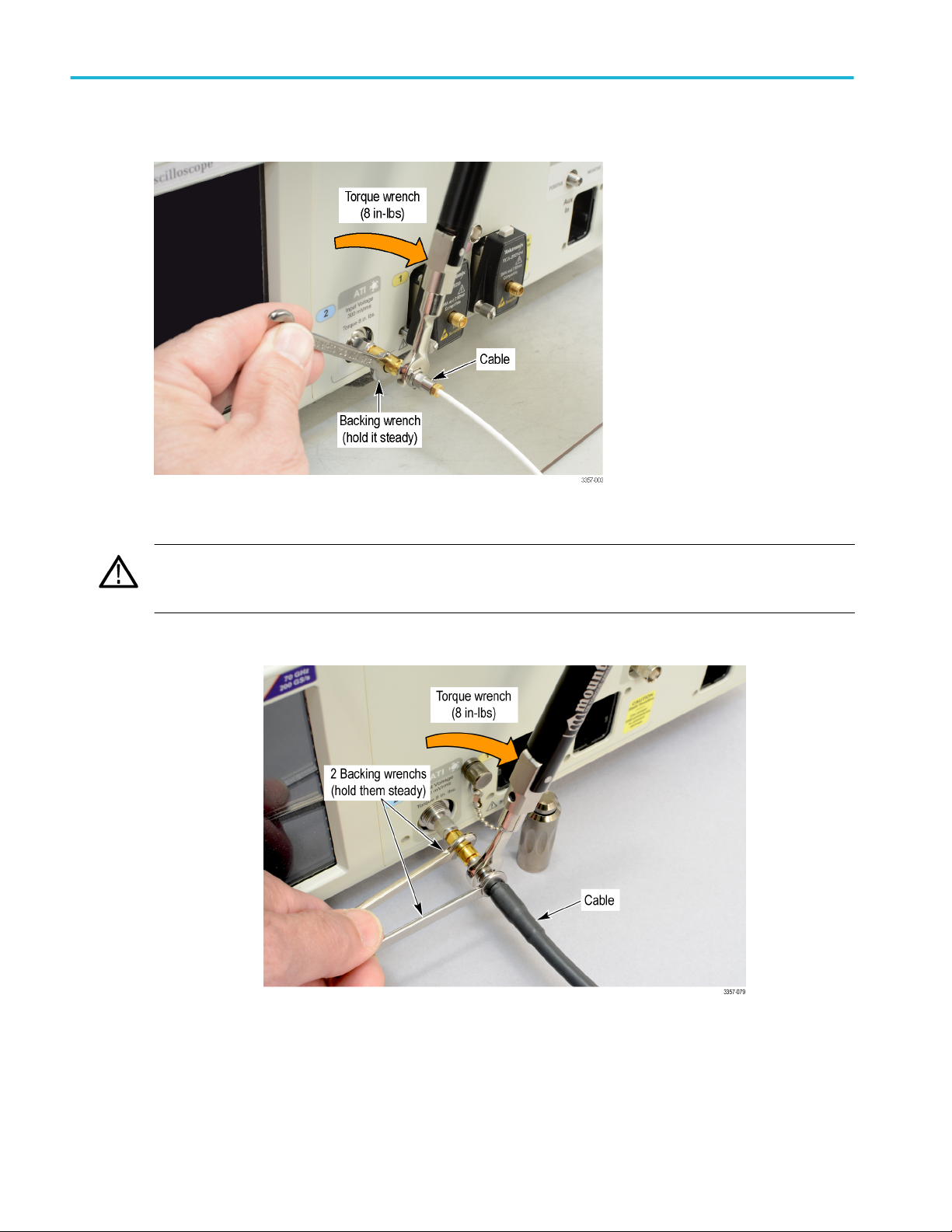
4. Use the supplied torque wrench to tighten (8 inch-pounds) your cable connector to the connector saver.
Figure 3: Installing a cable
CAUTION. Failure to prevent rotation of the center conductors when making connections to the ATI input will damage your
instrument. If necessary use a second backing wrench on the cable, to prevent its rotation. Use the supplied torque wrench
to tighten (8 inch-pounds) all connectors.
5. If necessary use a second backing wrench on the cable, to prevent its rotation.
Figure 4: Use a second backing wrench
8 DPO70000SX Series User
Page 29

Install your instrument
Power on the instrument
1. Connect the AC power cord to the rear of the instrument.
2. Use the front-panel power button to switch the instrument on.
The power button indicates instrument power states:
■
No light – no power applied
■
Green – powered on
DPO70000SX Series User 9
Page 30

Install your instrument
Power off the instrument
1. Press the front-panel power button to shut down the instrument.
NOTE. If powering off a multi-instrument configuration, power off the master first.
The shutdown process takes approximately 30 seconds to complete, placing the instrument in standby mode. Alternatively,
use the Windows Shutdown menu.
NOTE. You can force an immediate shutdown by pressing and holding the power button for four seconds. Unsaved data is
lost.
2. To completely remove power to the instrument, perform the shutdown just described, and then remove the power cord from
the instrument.
Multi-instrument configuration
Connect instruments in a multi-instrument configuration to create an up to 4 channel, highest bandwidth, and highest sample rate
system with synchronized trigger and sample clock.
Instrument stacking
Multiple instruments may be stacked to save space and allow shorter cables and more convenient connections.
WARNING. When using an instrument upside down, be careful to avoid pinching your fingers.
10 DPO70000SX Series User
Page 31

Install your instrument
DPO70000SX Series User 11
Page 32
Install your instrument
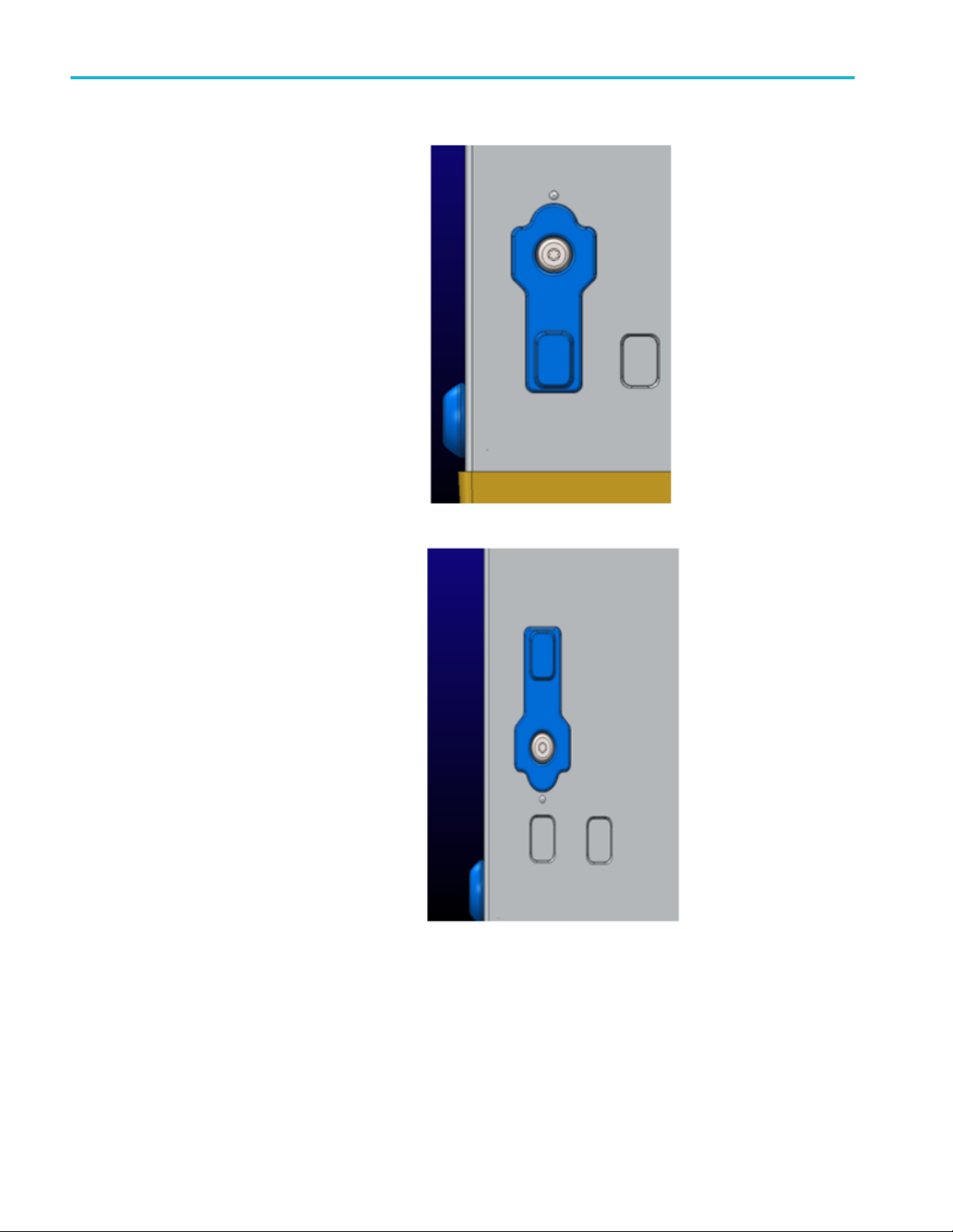
Standard orientation of the top feet is useful
when placing an instrument inverted on the
work bench. Standard orientation of the top
feet is also use when stacking an OM4000 on
the instrument.
Use the rotated orientation of the top feet to
stack two instruments on top of each other.
When stacking two instruments, the bottom feet sit in the holes exposed when the top feet are rotated.
12 DPO70000SX Series User
Page 33

Install your instrument
Before startup
All instruments in a multi-Instrument configuration must be connected properly before powering on the instruments. If the
configuration is changed after the instruments are powered on, a system restart may be required.
If an instrument is not connected in a multi-instrument configuration, the instrument powers on in its stand alone mode, not multiinstrument mode.
UltraSync™ bus cable
An UltraSync bus cable will connect any multi-instrument configuration capable instrument.
All cables must be connected to the instruments prior to power up. A restart will be required if the instruments are turned on
before the cables are connected.
UltraSync™ bus cable connection order
Connect UltraSync bus cable bundles to the Master:
1. Select which instrument will be the Master instrument.
At the Master instrument connect each UltraSync cable bundle set to the designated ports (start with the To Extension B
ports; then if connecting a third instrument use the To Extension C ports, and then if connecting a fourth instrument use the
To Extension D ports):
2. Connect the clock cable to the 12.5 GHz Clock Out connector (8 in-lbs torque).
3. Connect the Trigger cable to the Trigger connector.
4. Connect the PCIe cable to the PCIe connector.
DPO70000SX Series User 13
Page 34

Install your instrument
Connect UltraSync bus cable bundles to the Extension.
At the Extension, connect each UltraSync cable bundle set to the designated ports:
1. Connect the clock cable to the 12.5 GHz Clock In connector (8 in-lbs torque).
2. Connect the trigger cable to the To Master Trigger connector.
3. Connect the PCIe cable to the PCIe connector
14 DPO70000SX Series User
Page 35
Install your instrument
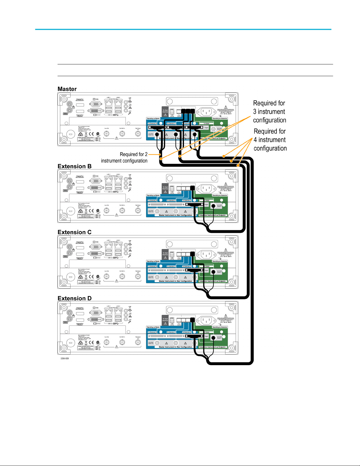
Master and extension connection order
Connect each extension instrument to the master instrument sequentially from left to right (Extension B, C, and then D).
NOTE. Connect the extensions to the master in a star pattern, do not daisy chain the instruments.
If powering off a multi-instrument system, power off the master first.
DPO70000SX Series User 15
Page 36

Install your instrument
Multi-instrument power on
During the start-up process the instrument checks to see if instruments are connected in a Multi-instrument configuration. If
instruments are not connected, the instrument powers up in stand-alone mode. If instruments are connected, the configuration is
validated. If the configuration is not valid, guidance is provided to help you create a valid configuration.
NOTE. After successful power on of your multi-instrument system, wait for the warm-up time to complete, and then run Signal
Path Compensation.
The following image shows an extension with a connection that is invalid and provides guidance to correct the connection
(provide the missing connection to the master).
The following image shows a master connected incorrectly and provides guidance to fix the problem (provide the missing
connection to the extension).
16 DPO70000SX Series User
Page 37

Install your instrument
The following images show the master and extension with valid connections.
DPO70000SX Series User 17
Page 38

Install your instrument
After the multi-instrument connections are verified and the instruments display their operating status displays, the master displays
its status and timer display. Pause the timer if you have additional changes to make before the oscilloscope application starts.
Press Start Scope to bypass the timer. When the timer runs down, the oscilloscope application starts.
18 DPO70000SX Series User
Page 39
Install your instrument
If your multi-instrument configuration includes ATI instruments, you have the opportunity to select either ATI Channels or non-ATI
(TekConnect) Channels. In this example ATI Channels are selected.
NOTE. You also have the option to select Time Synchronized mode of all TekConnect channels. In this mode acquisitions are
time synchronized and the Master controls the horizontal, record length, and trigger settings of all TekConnect channels. To
ensure all channels are synchronized, operate the multi-instrument configuration in single sequence mode. Retrieve all
TekConnect channel data using programmable interface commands. Waveform data is not sent to the Master. If you plan to use
Time Synchronized mode, contact your Tektronix representative for additional information.
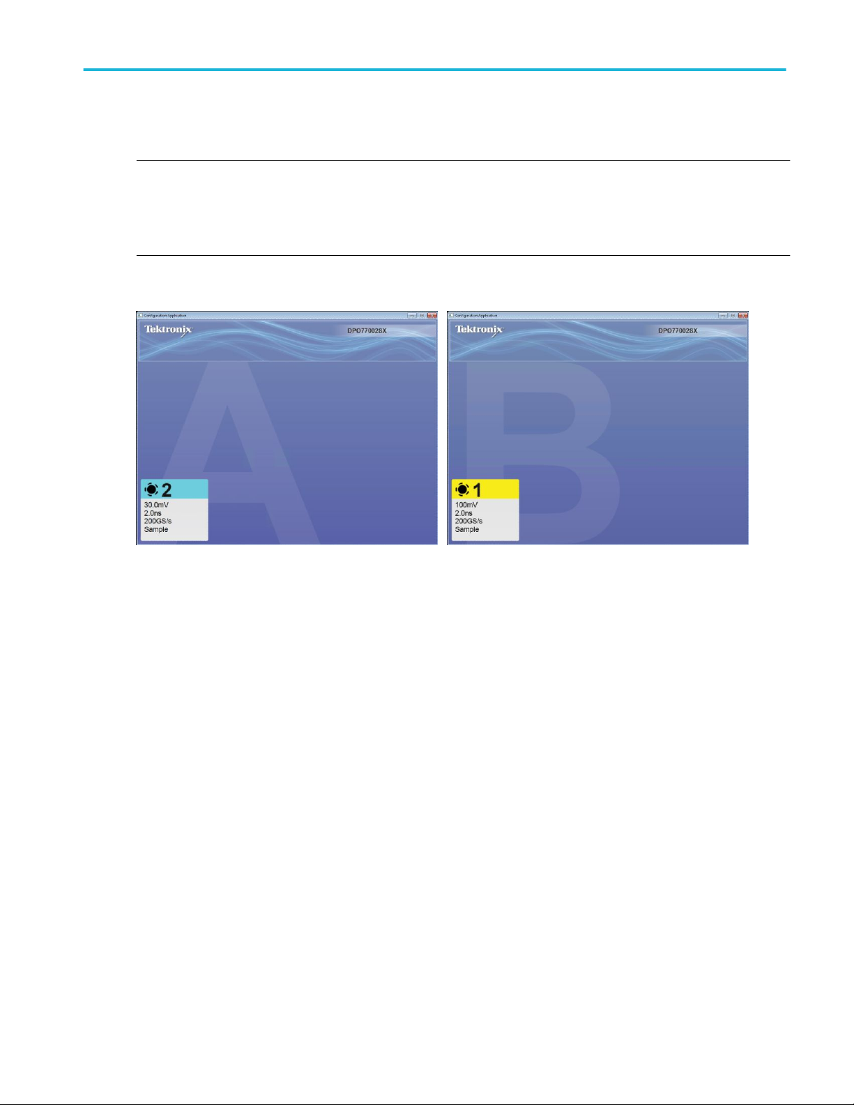
After the multi-instrument connections are verified, the instruments display their operating status displays. In this example the
Master (A) is acquiring on channel 2 (ATI). The Extension (B) is acquiring on channel 2 (ATI) and is displayed as channel 1.
The master display identifies itself as the Master and identifies the channels being acquired.
To switch between the Configuration Application and the oscilloscope display (on the oscilloscope), use Alt-Tab. To close the
Configuration Application, click the x. If the x is not visible, make the x visible by double clicking in the upper right hand corner of
the Configuration Application.
DPO70000SX Series User 19
Page 40

Install your instrument
After the multi-instrument system powers on, perform a signal path compensation. See Signal path compensation on page 26.
Switching between multi-instrument modes
To switch among ATI channels, TekConnect channels, and Time Synchronized modes, use the following procedure:
1. From the Vertical > Configuration menu
select either ATI, TekConnect, or
TimeSync.
20 DPO70000SX Series User
Page 41
Install your instrument
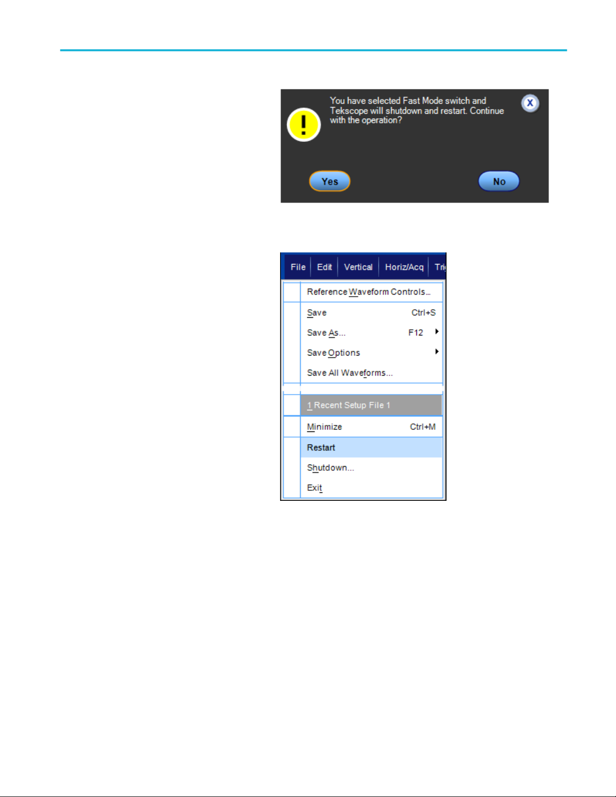
2. Click Yes to continue.
Restart of a multi-instrument system. To restart your multi-instrument system without powering down the oscilloscopes, do the
following step:
1. To shut down the Configuration Manager
and all of the Scope applications and
then restart them without changing the
configuration mode, select File > Restart.
ATI versus TekConnect channels
ATI channels provide up to 70 GHz bandwidth and 200 GS/s sample rate and the lowest noise. When using the ATI channel, the
TekConnect channels are not available.
TekConnect channels have up to 33 GHz bandwidth and 100 GS/s sample rate. TekConnect channels offer multiple connection
options with TCA adapters, and are compatible with a wide range of performance probes.
DPO70000SX Series User 21
Page 42

Install your instrument
Multi-instrument status displays
In a multi-instrument configuration, the display shows status information such as: channel numbers, on/off, run/stop, Arm/trig'd,
and UltraSync connectivity information. The master instrument also displays the trigger setup and the channels being acquired
and displayed.
Available features
Features discussed in this manual that are available on some instruments or configurations are noted in the tables.
Table 5: Stand-Alone instrument
Feature DPO77002SX
DPO75902SX
DPO75002SX
State (Clocked
Available on TekConnect channels Available
Pattern) trigger
XYZ mode Available on TekConnect channels Available
Equivalent time
Available on TekConnect channels Available
acquisitions
HiRes and peak
Available on TekConnect channels Available
detect
FastAcq Available on TekConnect channels Available
Roll mode Available on TekConnect channels Available
IRE and MV graticule
Available on TekConnect channels Available
modes
DPO73304SX
DPO72304SX
DPO71604SX
DPO71304SX
22 DPO70000SX Series User
Page 43
Install your instrument
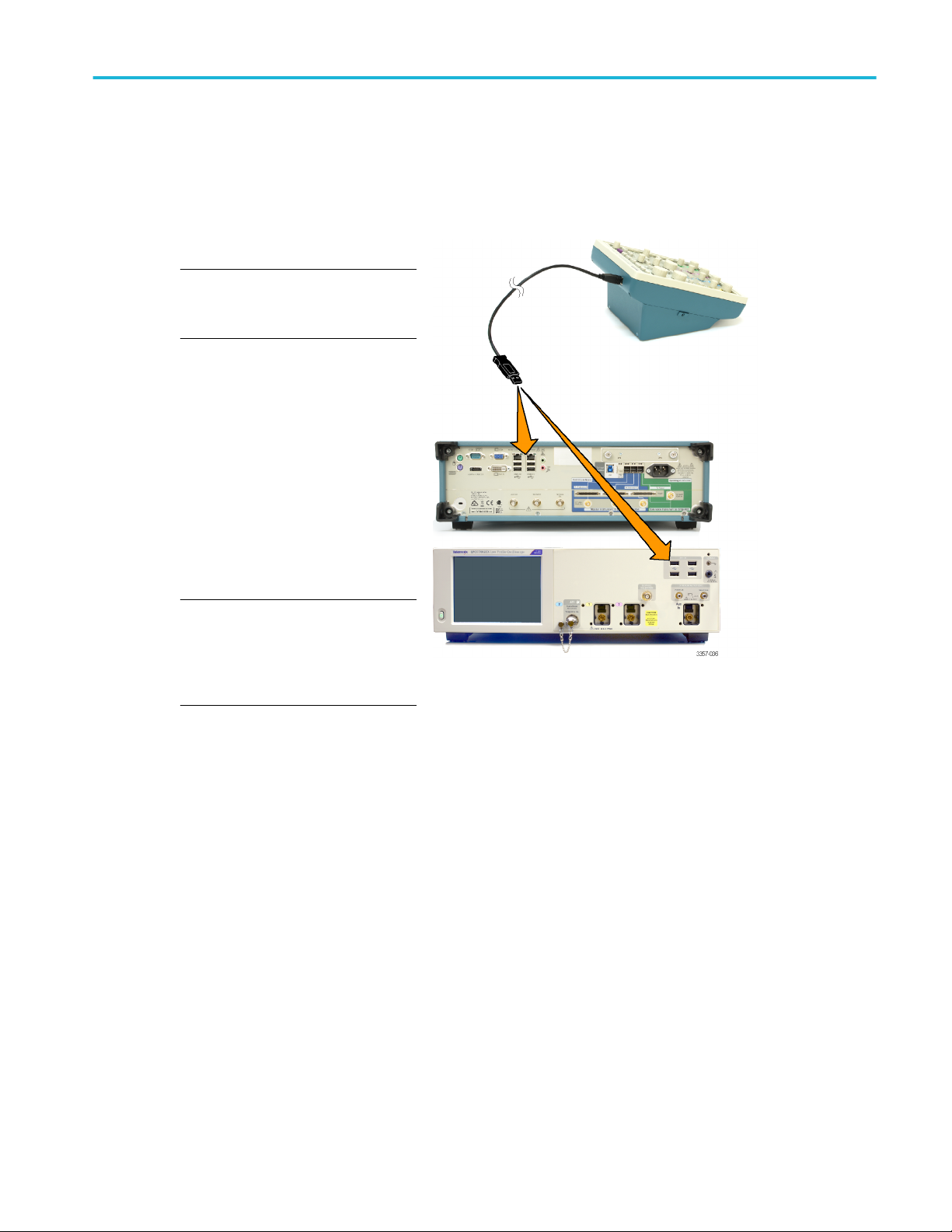
DPO7AFP Auxiliary Front Panel (optional)
The DPO7AFP is an optional plug-in panel that provides physical knobs and buttons to control the DPO70000SX series
oscilloscope. To connect the DPO7AFP:
1. Close the TekScope application.
NOTE. The TekScope application must
be closed before connecting the
DPO7AFP.
2. Plug the DPO7AFP into any USB port on
the DPO70000SX. Wait until the
Windows OS recognizes and loads the
required drivers.
3. Start the TekScope application. The
panel LEDs will light when TekScope
connects to the panel.
4. To verify that the DPO7AFP is working,
push any channel button and observe
that the TekScope application enables or
disables the selected channel
NOTE. If you unplug the DPO7AFP while
TekScope is running, you will need to
close TekScope, reconnect the
DPO7AFP, and restart TekScope to use
the DPO7AFP.
Inspect the instrument
Every time you power on the instrument, the instrument automatically performs the power-on self test diagnostics.
Verify internal diagnostics pass
Use the following procedures to verify the functionality of your instrument.
DPO70000SX Series User 23
Page 44

Install your instrument
1. Power on the instrument.
2. Select Instrument Diagnostics....
3. Click Run. The test results appear in the
diagnostics control window.
4. Verify that all tests pass. If diagnostic
failures occur, contact your local
Tektronix service personnel.
Activating Windows 10
The copy of Microsoft Windows 10 that ships with this product is shipped in Deferred Activation mode. Microsoft has a default
activation method that requires a connection to the Internet. If you are not able to connect to the Internet, you can activate
Windows 10 by phone or you can continue to operate in Deferred Activation mode.
First time activation. You can activate Windows 10 either of the following ways.
1. Connect the instrument to the Internet. Windows will automatically activate. You can also go to System Properties to
connect and activate.
2. Call Microsoft and speak with a representative to activate Windows 10. Contact information and a unique activation code
(installation ID) will appear in a pop up window.
Activation with removable drives. If the SSD is removed from one instrument and inserted into another instrument, then the
activation process will need to run again on the second instrument. If the second instrument is not connected to the Internet, the
activation will fail and an Activate Windows watermark will display on the screen. To activate Windows and remove the
watermark, you must connect to the Internet or call Microsoft.
24 DPO70000SX Series User
Page 45

Install your instrument
Windows interface guidelines
Because the instrument uses the Microsoft Windows interface, you have open access to the Windows operating system. You can
access the Windows desktop to load and run other Windows-based applications such as Microsoft Excel.
Follow these guidelines to avoid making operating system changes that might cause problems while using the instrument:
■
Be careful when making changes in the Control Panel. Avoid making changes to any controls with which you are unfamiliar.
■
Do not delete or change any system fonts; this can affect the quality of the display.
■
Be careful when making changes to the system Display properties. Changing settings such as resolution, text size, fonts,
and orientation affects the usability of the display and the touchscreen.
■
Do not change the contents of the Windows folder or the Program Files\Tektronix\AWG70000\ folder.
■
Do not change the BIOS settings; this can affect the overall operation of the instrument.
DPO70000SX Series User 25
Page 46

Install your instrument
Signal path compensation
Perform the Signal Path Compensation (SPC) regularly to ensure that your measurements have the highest level of accuracy.
Tektronix considers it a best practice to run SPC when using the instrument to measure signals with higher sensitivity (10 mV/div
and lower) settings regardless of temperature shift or time since it was last run. Failure to perform SPC may result in the
instrument not meeting warranted performance levels.
SPC corrects for DC inaccuracies caused by temperature variation or by long-term drift. SPC optimizes the acquisition system,
corrects DC offset, and interleave calibration. SPC is adversely affected by input signals with AC components.
Use this procedure to optimize the acquisition system:
■
If the temperature has changed more than 5 °C (9 °F) since the last signal path compensation (SPC)
■
If using the instrument to measure signals with higher sensitivity (10 mV/div and lower) run SPC at least once a week
■
If the front panel SPC status icon is not green
■
If you replace or insert drive media
■
If you change the configuration of your multi-instrument system, such as changing which instrument is the master or an
extension.
1. Prerequisites:
■
Instrument must be powered on until
Utility > Instrument Calibration >
Temperature Status is Ready.
■
All channel input signals must be
removed.
■
If the timebase external reference
mode is selected, leave the external
reference signal connected and
active.
26 DPO70000SX Series User
Page 47

Install your instrument
2. Select Instrument Calibration.
3. When the Temperature Status changes
to Ready, click Run SPC to start the
calibration. Calibration may take 10 to
15 minutes.
NOTE. Before running the SPC
calibration, remove all channel input
signals.
NOTE. If you use a drive that has not had
SPC run while in the current instrument,
you will see a no prior SPC warning
message. If you see this warning, run
SPC.
Utility menu on DPO70000SX
instruments
Calibration menu on DPO70000SX instruments
DPO70000SX Series User 27
Page 48
Install your instrument
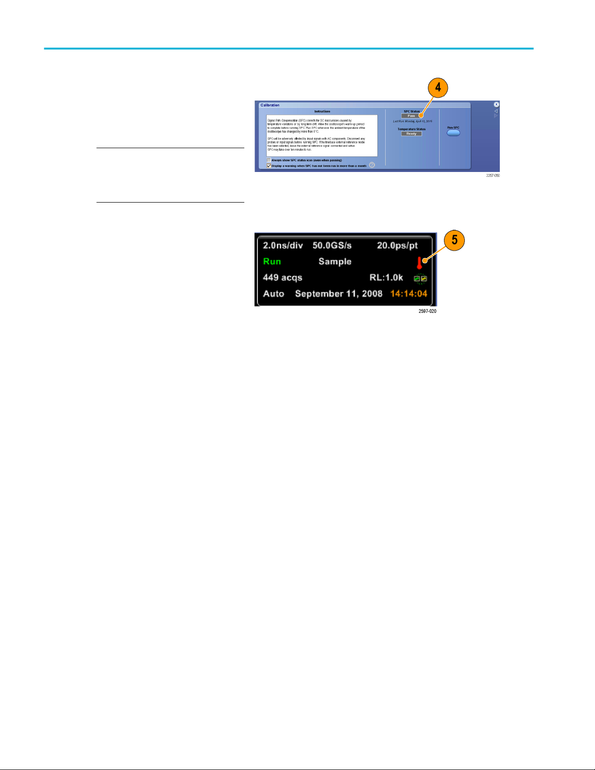
4. If the instrument does not pass,
recalibrate the instrument, or have the
instrument serviced by qualified service
personnel.
NOTE. To always show the SPC status
icon or display a warning when SPC has
not been run in more than a month, click
the corresponding check box.
Calibration menu on DPO70000SX instruments
5. If the SPC needed icon is red, perform a
signal path compensation.
Check the color of the SPC Status icon:
■
Green indicates that SPC
successfully passed and the
temperature is stable.
■
Yellow indicates that the instrument
is in the warm up state or that it has
been over 30 days since SPC was
last run.
■
Red indicates that SPC needs to be
run (the temperature has varied
more than 5 °C, SPC failed, or SPC
has not been run).
28 DPO70000SX Series User
Page 49

Install your instrument
Connecting to a network
Connect your instrument to a network for
printing, file sharing, internet access, and other
functions. Consult with your network
administrator and use the standard Windows
utilities to configure the instrument for your
network.
Use the Remote Desktop Connection of
Windows to control and view the instrument
remotely.
DPO70000SX Series User 29
Page 50

Install your instrument
Adding a second monitor
You can operate the instrument while using Windows and installed applications on an external monitor. Follow the procedure
below to set up a dual monitor configuration.
1. Turn power off.
2. Connect second monitor.
3. Connect keyboard.
4. Connect mouse.
5. Turn instrument power on.
6. Turn monitor power on.
Activating Windows 10
The copy of Microsoft Windows 10 that ships with this product is shipped in Deferred Activation mode. Microsoft has a default
activation method that requires a connection to the Internet. If you are not able to connect to the Internet, you can activate
Windows 10 by phone or you can continue to operate in Deferred Activation mode.
First time activation
You can activate Windows 10 either of the following ways.
1. Connect the instrument to the Internet. Windows will automatically activate. You can also go to System Properties to
connect and activate.
2. Call Microsoft and speak with a representative to activate Windows 10. Contact information and a unique activation code
(installation ID) will appear in a pop up window.
30 DPO70000SX Series User
Page 51

Install your instrument
Activation with removable drives
If the SSD is removed from one instrument and inserted into another instrument, then the activation process will need to run
again on the second instrument. If the second instrument is not connected to the Internet, the activation will fail and an Activate
Windows watermark will display on the screen. To activate Windows and remove the watermark, you must connect to the
Internet or call Microsoft.
Restoring instrument operating system and product software
You can restore the instrument’s Windows Operating System directly from the instrument. The instrument does not ship with an
operating system restore disc.
To restore or update the product software, you need to download the current version from the Tektronix web site.
NOTE. Restoring or updating the product software does not require that you restore the Windows operating system.
Operating system restore
CAUTION. Using the restore process reformats the hard drive and reinstalls the operating system. All saved data is lost. If
possible, save important files to external media before performing a system restore.
The Windows operating system installed is designed for this instrument’s hardware and product software. Installing a version
other than the one provided will not function properly.
After the operating system is installed, you need to download the product software installation package from the Tektronix web
site and reinstall the software.
Internal recovery utility
This is the preferred method to restore a damaged Windows Operating System. This method restores the Windows Operating
System using the Acronis Startup Recovery Manager. The Acronis software reinstalls the operating system using restore images
preinstalled on the hard drive.
This method retains the restore images, providing the ability to repeat the restore process.
1. Attach the keyboard to the instrument.
2. Restart the instrument. During the boot-up process you will see the following message at the top of the screen:
Starting Acronis Loader... press F5 for Acronis Startup Recovery Manager
NOTE. To successfully complete the system restore, you must use the Windows version of the Acronis software. Using a
generic MAC keyboard starts the DOS version of the Acronis software. Do not use a MAC keyboard.
3. Repeatedly press the F5 key until the Acronis True Image Tool opens. There is a 15-second time period from when the
message appears until the instrument proceeds with the normal instrument startup. If the instrument does not open the
Acronis application, power off the instrument, then power on the instrument and try again.
4. Click Restore.
5. In the Confirmation dialog box, click Yes to restore the instrument operating system, or No to exit the restore process. The
restore process takes approximately 30 minutes; the actual time depends on the instrument configuration.
DPO70000SX Series User 31
Page 52

Install your instrument
Product software installation
NOTE. For DPO77002SX instruments you must order the product software from Tektronix.
1. Download the product software installation package. The installation package contains:
■
Instructions
■
Product software installer
2. Install the product software following all on-screen prompts.
32 DPO70000SX Series User
Page 53

Getting acquainted with your instrument
Front-panel connectors
Figure 5: ATI with TekConnect channels
DPO70000SX Series User 33
Page 54

Getting acquainted with your instrument
Figure 6: TekConnect channels
Table 6: Front-panel connectors
Identifier Connector Description
1 USB 2.0 Four USB connectors.
2 Chassis ground Banana type ground connection.
Ground through 1 MΩ resistor Banana type ground connection.
Discharge the static voltage from your body by wearing a grounded
antistatic wrist strap while connecting and disconnecting cables and
TekConnect adapters.
3 DC Probe Calibration Probe calibration output
4 1, 2, 3, and 4(Analog inputs) These connectors supply analog signals.
5 Aux In Auxiliary trigger input
6 Differential Fast Edge Differential fast edge step output.
34 DPO70000SX Series User
Page 55
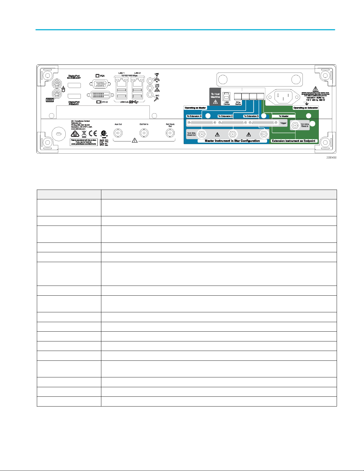
Getting acquainted with your instrument
Rear-panel connectors
Table 7: Rear-panel connectors
Connector Description
PCIe PCIe port to connect external devices or to configure multi-instrument systems.
12.5 GHz Clock In SMA type connector to provide an external clock signal used in multi-instrument configurations.
12.5 GHz Clock Out SMA type connector to provide a high speed clock that is related to the sample rate. This clock is used in
multi-instrument configurations.
Trigger UltraSync trigger bus.
LAN RJ-45 connectors to connect the instrument to a network.
USB 3.0 Four USB 3.0 Host connectors (type A) to connect devices such as a mouse, keyboard, or other USB
devices. Tektronix does not provide support or device drivers for USB devices other than the supplied
mouse and keyboard.
USB USB device connector
VGA VGA port to connect a monitor for extended desktop operation. To connect a DVI monitor to the VGA
connector, use a DVI-to-VGA adapter.
DVI-D Use the DVI-D Video port to send the instrument display to a projector or to a flat-panel LCD monitor.
Display port These connectors provide digital display interfaces
PS/2 mouse This connector is for a PS/2 mouse.
PS/2 keyboard This connector is for a PS/2 keyboard
Audio These connectors provide microphone input, line in, and line out.
Auxiliary output SMA type connector provides a TTL-compatible, negative polarity pulse when the instrument triggers or
when certain other events occur, such as a mask test failure or completion.
Reference output SMA type connector to provide a synchronization signal to external devices.
External reference input SMA type connector to provide an external reference clock input.
Power Power cord input.
DPO70000SX Series User 35
Page 56

Getting acquainted with your instrument
Interface and display
The menu bar mode provides access to commands that control all of the instrument features and functions. The toolbar mode
provides access to the most common features.
1. Menu Bar: Access to data I/O, printing,
online help, and instrument functions
2. Buttons/Menu: Click to toggle between
toolbar and menu bar modes and to
customize your toolbar
3. Multipurpose Knob Readouts: Adjust
and display parameters controlled by the
multipurpose knobs
4. Display: Live, reference, math, and bus
waveforms display here, with cursors
5. Waveform Handle: Click and drag to
change vertical position of a waveform or
bus. Click the handle and change the
position and scale using the multipurpose
knobs.
6. Controls Status: Quick reference to
vertical selections, scale, offset, and
parameters. Probe status is provided for
some probe tips.
7. Readouts: Display cursor and
measurement readouts in this area.
Measurements are selectable from the
menu bar or toolbar. If a control window
is displayed, some combinations of
readouts move to the graticule area.
WARNING. If there is vertical clipping, there may be a dangerous voltage on the probe tip, but the readout will indicate a low
voltage. A symbol appears in the measurement readout if a vertical clipping condition exists. Automatic amplitude-related
measurements where the signal is vertically clipped produce inaccurate results. Clipping also causes inaccurate amplitude
values in waveforms that are stored or exported for use in other programs. If a math waveform is clipped, it will not affect
amplitude measurements on that math waveform.
8. Status: Display of acquisition status, mode, and number of acquisitions; trigger status; date; time; and quick reference to
record length and horizontal parameters
36 DPO70000SX Series User
Page 57

Getting acquainted with your instrument
1. Buttons/Menu: Click to toggle between
toolbar and menu bar modes and to
customize the toolbar
2. Drag cursors to measure waveforms on
screen
3. Drag the position icons to reposition a
waveform
4. Click the icon to assign the multipurpose
knobs to waveform vertical position and
scale
5. Drag across the waveform area to create
a box for zooming, enabling/disabling
histograms, gating measurements, and
adding and controlling visual trigger areas
6. Drag icon to change the trigger level
DPO70000SX Series User 37
Page 58

Getting acquainted with your instrument
Control panel
NOTE. These controls are available on the Auxiliary Front Panel accessory. The functions these controls perform are available in
the instrument menus.
1. Push to automatically set up the vertical,
horizontal, and trigger controls based on
selected channels.
2. Push to return settings to default values.
3. Push to make a hard copy or save a
screen capture.
4. Push to turn on MultiView Zoom and add
a magnified graticule to the display.
5. Horizontally scale, position, delay, and
set record length (resolution) of all
waveforms.
6. Use to start and stop acquisition, start a
single acquisition sequence, clear data,
or start fast acquisitions.
7. Use to set the trigger parameters. Push
Advanced to display additional trigger
functions. The Arm, Ready, and Trig'D
lights show the acquisition status.
8. Turn to adjust waveform intensity.
9. Turn to adjust parameters selected from
the screen interface. Push to toggle
between normal and fine adjustment.
10. Push to turn cursors on or off.
11. Use to search and mark waveforms.
12. Push to turn the touch screen on and off.
13. Turn channel displays on and off.
Vertically scale, position, or offset the
waveform. Toggle between position and
offset.
38 DPO70000SX Series User
Page 59
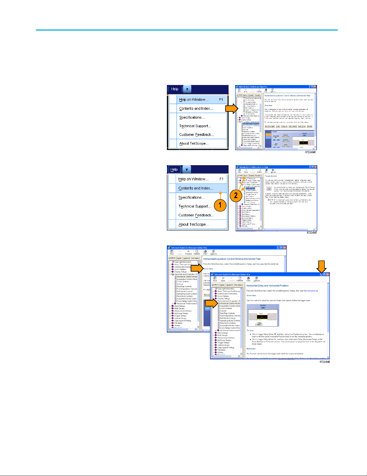
Getting acquainted with your instrument
Accessing online help
In-depth information is available in the online help on all the features of your instrument.
To access context-sensitive help on the active
window, select Help > Help on Window... or
press F1.
1. To access any topic in the help system,
select Help > Contents and Index....
2. Use the Contents, Index, Search, or
Favorites tab to select the topic, and then
click Display.
To navigate within the help system:
■
Click a button in a help window to
navigate between the Overview and
specific topics.
■
Click the Minimize button in the help
window to move help out of the way so
you can operate the instrument.
■
Click Alt and Tab to see the last help
topic again.
DPO70000SX Series User 39
Page 60

Getting acquainted with your instrument
Accessing menus and control windows
Access menus and control windows using the following techniques:
■
Click a menu, and then select a
command.
■
For a shortcut menu, right-click anywhere
in the graticule or on an object. The
shortcut menu is context sensitive and
varies with the area or object where you
right-clicked. Some examples are shown
in the figure at right.
■
In the toolbar mode, click a button to
quickly access a setup control window.
See Interface and display.
40 DPO70000SX Series User
Page 61

Inspect your instrument
Use the following procedures to verify the functionality of your instrument.
Verify internal diagnostics pass
1. Power on the instrument.
2. Select Instrument Diagnostics....
3. Click Run. The test results appear in the
diagnostics control window.
4. Verify that all tests pass. If diagnostic
failures occur, contact your local
Tektronix service personnel.
DPO70000SX Series User 41
Page 62

Inspect your instrument
42 DPO70000SX Series User
Page 63

Acquisition
This section contains concepts of and procedures for using the acquisition system.
Signal path compensation
Perform the Signal Path Compensation (SPC) regularly to ensure that your measurements have the highest level of accuracy.
Tektronix considers it a best practice to run SPC when using the instrument to measure signals with higher sensitivity (10 mV/div
and lower) settings regardless of temperature shift or time since it was last run. Failure to perform SPC may result in the
instrument not meeting warranted performance levels.
SPC corrects for DC inaccuracies caused by temperature variation or by long-term drift. SPC optimizes the acquisition system,
corrects DC offset, and interleave calibration. SPC is adversely affected by input signals with AC components.
Use this procedure to optimize the acquisition system:
■
If the temperature has changed more than 5 °C (9 °F) since the last signal path compensation (SPC)
■
If using the instrument to measure signals with higher sensitivity (10 mV/div and lower) run SPC at least once a week
■
If the front panel SPC status icon is not green
■
If you replace or insert drive media
■
If you change the configuration of your multi-instrument system, such as changing which instrument is the master or an
extension.
1. Prerequisites:
■
Instrument must be powered on until
Utility > Instrument Calibration >
Temperature Status is Ready.
■
All channel input signals must be
removed.
■
If the timebase external reference
mode is selected, leave the external
reference signal connected and
active.
DPO70000SX Series User 43
Page 64
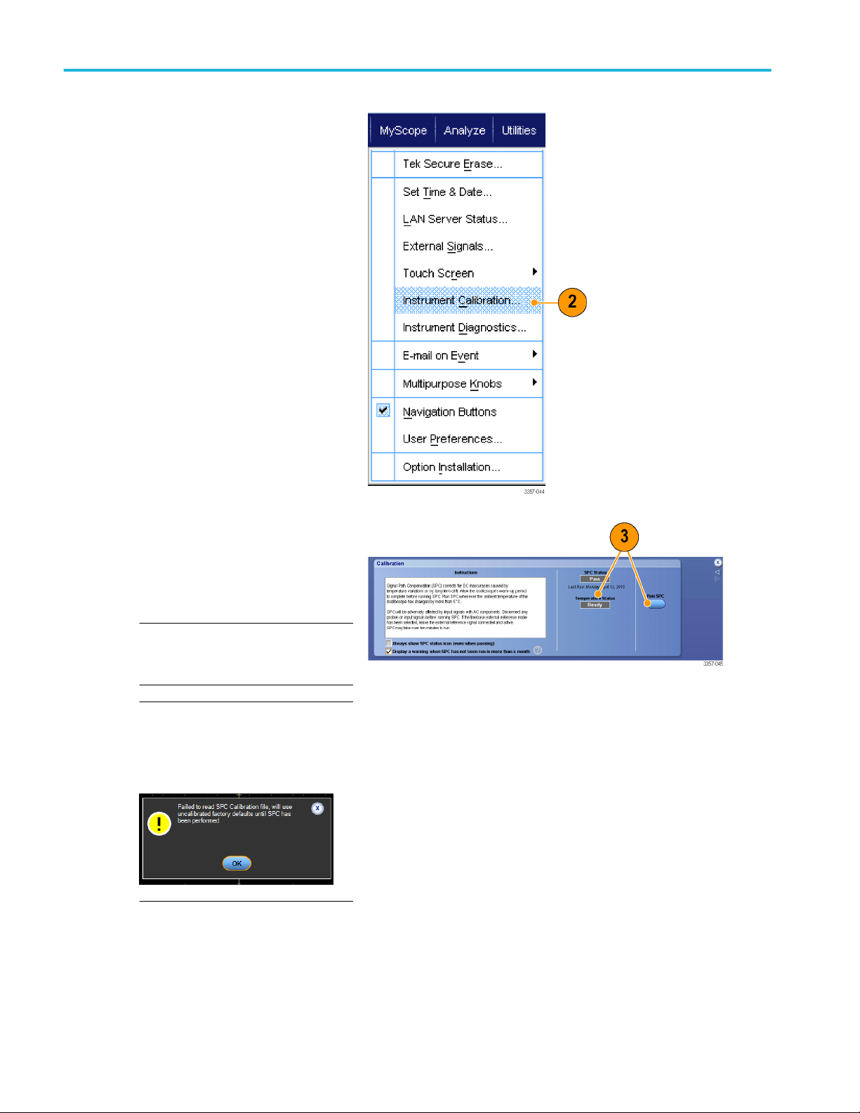
Acquisition
2. Select Instrument Calibration.
3. When the Temperature Status changes
to Ready, click Run SPC to start the
calibration. Calibration may take 10 to
15 minutes.
NOTE. Before running the SPC
calibration, remove all channel input
signals.
NOTE. If you use a drive that has not had
SPC run while in the current instrument,
you will see a no prior SPC warning
message. If you see this warning, run
SPC.
Utility menu on DPO70000SX
instruments
Calibration menu on DPO70000SX instruments
44 DPO70000SX Series User
Page 65

Acquisition
4. If the instrument does not pass,
recalibrate the instrument, or have the
instrument serviced by qualified service
personnel.
NOTE. To always show the SPC status
icon or display a warning when SPC has
not been run in more than a month, click
the corresponding check box.
Calibration menu on DPO70000SX instruments
5. If the SPC needed icon is red, perform a
signal path compensation.
Check the color of the SPC Status icon:
■
Green indicates that SPC
successfully passed and the
temperature is stable.
■
Yellow indicates that the instrument
is in the warm up state or that it has
been over 30 days since SPC was
last run.
■
Red indicates that SPC needs to be
run (the temperature has varied
more than 5 °C, SPC failed, or SPC
has not been run).
DPO70000SX Series User 45
Page 66
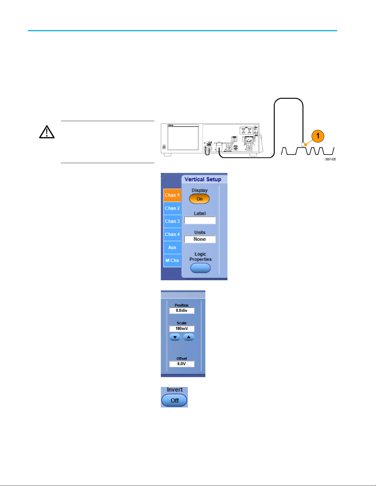
Acquisition
Setting up analog signal input
Use the drop down menus or the Auxiliary Front Panel to set up your instrument to acquire the signal.
If using the drop down menus, do the following steps:
1. Connect the probe or cable to the input
signal source.
CAUTION. To prevent damage to the
instrument, always wear an antistatic
wrist strap when making connections to
the instrument and observe the maximum
input voltage ratings for input connectors.
2. Select the input channel: Select Vertical
> Vertical Setup. Select the tab for the
channel you want to select, and then
press the Display button to toggle the
channel on or off.
3. Select Horiz/Acq > Autoset.
4. Select Vertical > Vertical Setup. Adjust
the vertical position, scale, and offset:
Double click the Position, Scale, and
Offset controls and use the pop-up
keypad make the adjustment.
5. If you want to invert the input signal, click
the Invert button to toggle invert on and
off. The Invert button is in the Vertical
Setup menu or the Deskew/Attenuation/
Invert menu.
46 DPO70000SX Series User
Page 67
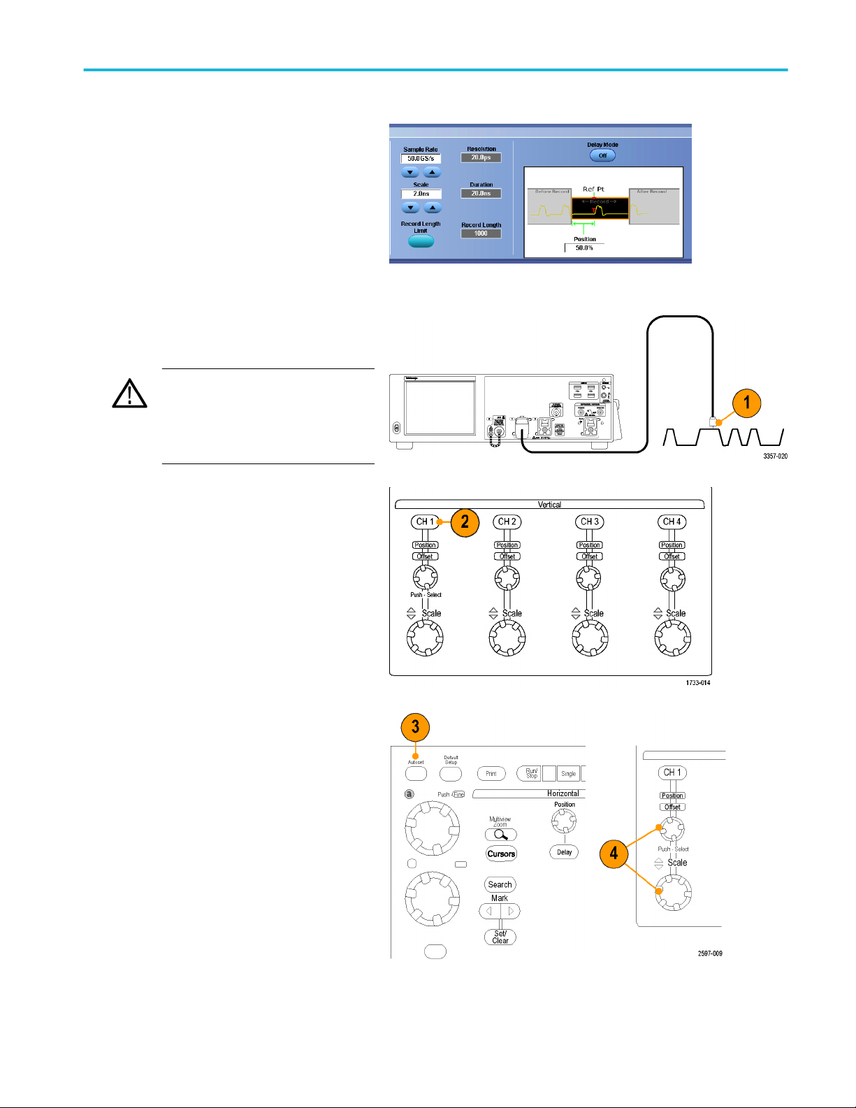
Acquisition
6. Select Horiz/Acq > Horizontal/
Acquisition Setup. Adjust the horizontal
position and scale: Double click the
Position and Scale controls and use the
pop-up keypad to make the adjustment.
The horizontal position determines the
number of pretrigger and posttrigger
samples.
If using the Auxiliary Front Panel, do the following steps:
1. Connect the probe or cable to the input
signal source.
CAUTION. To prevent damage to the
instrument, always wear an antistatic
wrist strap when making connections to
the instrument and observe the maximum
input voltage ratings for input connectors.
2. Select the input channel.
3. Select Horiz/Acq then Autoset.
4. Adjust the vertical position, scale, and
offset.
DPO70000SX Series User 47
Page 68

Acquisition
5. Adjust the horizontal position and scale.
The horizontal position determines the
number of pretrigger and posttrigger
samples.
Using default setup
1. To quickly return to the factory default
settings, select Recall Default Setup
from the file menu or push DEFAULT
SETUP on the Auxiliary Front Panel.
48 DPO70000SX Series User
Page 69

Acquisition
Using autoset
Use Autoset to quickly and automatically set up the instrument (acquisition, horizontal, trigger, and vertical) based on the
characteristics of the input signal. Autoset makes adjustments to the signal such that the waveform displays two or three cycles
with the trigger level near the midlevel.
1. Connect the probe, and then select the
input channel. See Setting up analog
signal input on page 46.
2. To execute an Autoset, select Horiz/Acq
and then Autoset or push the AUTOSET
button on the Auxiliary Front Panel.
3. Click Undo to undo the last Autoset.
Parameters that are not affected by
Autoset retain their settings.
Quick tips
■
Autoset automatically sets up the analog channels.
■
On instruments with iCapture, autoset automatically sets up the iCapture channels.
■
To position the waveform appropriately, Autoset may change the vertical position. Autoset may also adjust vertical offset.
■
If you use Autoset when one or more channels are displayed, the instrument selects the lowest numbered channel for
horizontal scaling and triggering. You can individually control the vertical scaling of each channel.
■
If you use Autoset when no channels are displayed, the instrument turns on channel one (Ch 1) and scales it.
■
Close Autoset Undo control window by clicking the X. After Autoset Undo closes, you can still undo the last Autoset by
selecting the Undo Last Autoset command from the Edit menu.
■
Stop the Autoset Undo control window from opening automatically by changing the User Preferences in the Utilities menu.
DPO70000SX Series User 49
Page 70

Acquisition
Probe compensation and deskew
To optimize measurement accuracy, see the instrument online help to perform the following procedures:
■
Compensate passive probes
■
Compensate active probes
■
Deskew input channels
Deskew Tool
From the Analyze menu, select Deskew Tool.
Overview
Use the Deskew Tool to compensate for propagation delays in your input signal path.
The deskew tool can be used either on a stand alone oscilloscope or between multiple DPO70000SX oscilloscopes connected
via ultrasync cables.
The deskew tool uses the oscilloscope trigger point to align all channels in time. This tool requires that a live signal be connected
to each channel. The live signals must be time synchronized to the trigger channel. The signals used for deskew can be the
same or opposite polarity compared to the trigger channel. For signals with the same polarity, the nearest edge with same
polarity as the trigger will be used as the reference edge for alignment. For differential signals, the nearest edge with the opposite
polarity as the trigger will be used for alignment.
50 DPO70000SX Series User
Page 71

Acquisition
1. Display Mode where the modes can be:
■
Standalone for a standalone oscilloscope
■
Multiscope for multiple ATI/TekConnect instruments
■
Time Sync mode
2. Channel selection - channels are grayed out when the channel is off. Press the channel button to toggle the channel on or
off.
3. Histogram view - Mean, StdDev and Population are shown.
4. Slope and Level - define the slope and level to use for deskewing.
■
Trigger uses the trigger slope and level as the reference polarity and level for the channel's alignment.
■
Rise uses the rising edge nearest the trigger point and allows you to adjust the level.
■
Fall uses the falling edge nearest the trigger point and allows you to adjust the level.
■
Either uses either the rising or falling edge and level.
NOTE. When using the deskew tool to align a differential pair select the trigger slope for the first channel and an edge
with its polarity opposite of the trigger's polarity.
5. Deskew To Mean - adds the measured skew value for each selected channel to the channel deskew value for each
respective channel.
6. Set 0 - resets all channel deskew values to 0.
7. Histogram Reset - clears the histograms of their population data.
8. Set Default - sets the Slope to Trigger on all channels and resets the histograms.
The tool works by precisely computing the difference between the trigger location and each channel's selected edge. The
computed values are shown in the histogram view. To align the oscilloscope channels, select the slope and level, wait for a
sufficient population to be accumulated (wait for the indicator near the To Mean button to turn green), and then press the To
Mean button.
Typically on DPO70000SX oscilloscopes it takes two accumulations and To Mean button presses to get femtosecond (fs) level
alignment. This is because when deskew values are set to 0 in the oscilloscope, the skew values can be in the picosecond (ps)
range. The difference in resolution between ps and fs is large. So the first try gets you close and the second gets into the fs
range.
DPO70000SX Series User 51
Page 72

Acquisition
To use
Use the Deskew Tool to compensate for propagation delays in your input signals.
1. Set the trigger mode to edge and adjust the trigger level on the reference channel until you have a stable trigger.
2. Select the channels to deskew. Ensure that each channel has a live signal attached and it has an edge that is within 0.5 UI
of the edge on the trigger channel.
3. Select the slope and level for each channel.
4. Wait for a sufficient population to be accumulated (the indicator near the To Mean button turns green)
5. Press the To Mean button.
6. Repeat steps 4 and 5 multiple times. The difference in resolution between ps and fs is large. So the first try gets you close
and the second gets into the fs range.
This figure is an example of fast edge signals before deskew:
This figure is an example of fast edge signals after deskew:
52 DPO70000SX Series User
Page 73

Acquisition
This figure is an example of differential signals before deskew:
DPO70000SX Series User 53
Page 74

Acquisition
This figure is an example of differential signals after deskew:
54 DPO70000SX Series User
Page 75
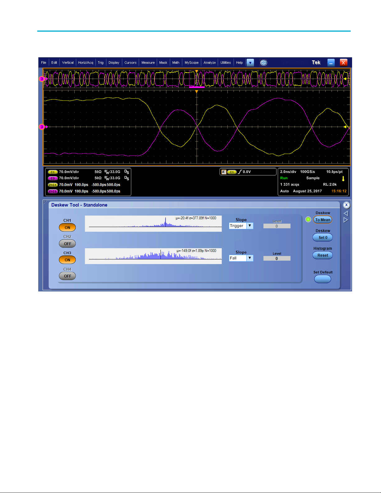
Acquisition
Acquisition concepts
Acquisition hardware
Before a signal is displayed, it must pass through the input channel where it is scaled and digitized. Each channel has a
dedicated input amplifier and digitizer. Each channel produces a stream of digital data from which the instrument extracts
waveform records.
DPO70000SX Series User 55
Page 76

Acquisition
Sampling process
Acquisition is the process of sampling an
analog signal, converting it into digital data,
and assembling it into a waveform record,
which is then stored in acquisition memory.
Real-Time sampling
In real-time sampling, the instrument digitizes
all of the points it acquires using one trigger
event. Use real-time sampling to capture
single-shot or transient events.
Interpolated Real-Time sampling
In interpolated real-time sampling, the
instrument digitizes all of the points it acquires
using one trigger event. If the instrument
cannot acquire enough samples for a
complete waveform at the maximum real-time
sample rate, it interpolates. Use interpolated
real-time sampling to capture single-shot or
transient events.
Equivalent-Time sampling
The instrument uses equivalent-time sampling
to extend its sample rate beyond its real-time
maximum sampling rate. Equivalent-time
sampling is only used if Equivalent Time is
selected and the time base is set to a
sampling rate that is too fast to create a
waveform record using real-time sampling.
The instrument makes multiple acquisitions of
a repetitive waveform to obtain the sample
density required for one complete waveform
record. Thus, equivalent time sampling should
only be used with repetitive signals.
56 DPO70000SX Series User
Page 77

Acquisition
Waveform record
The instrument builds the waveform record
through use of the following parameters:
■
Sample interval: The time between
sample points.
■
Record length: The number of samples
required to fill a waveform record.
■
Trigger point: The zero time reference in
a waveform record.
■
Horizontal position: When horizontal
delay is off, the horizontal position is a
percentage of the waveform record
between 0 and 99.9 percent. The trigger
point and the horizontal reference are at
the same time in the waveform record.
For example, if the horizontal position is
50 percent, then the trigger point is in the
middle of the waveform record. When
horizontal delay is on, the time from the
trigger point to the horizontal reference is
the horizontal delay.
Interpolation
Your instrument can interpolate between the samples it acquires when it does not have all of the actual samples it needs to fill
the waveform record. Linear interpolation computes record points between actual acquired samples by using a straight line fit.
Sin(x)/x interpolation computes record points using a curve fit between the actual values acquired. Sin(x)/x interpolation is the
default interpolation mode because it requires fewer actual sample points than linear interpolation to accurately represent the
waveform.
How the acquisition modes work
Acquisition mode
Sample mode retains the first sampled point from
each acquisition interval. Sample is the default
mode.
Peak Detect mode uses the highest and lowest of
all the samples contained in two consecutive
acquisition intervals. This mode only works with
real-time, noninterpolated sampling and is useful
for catching high frequency glitches.
Hi Res mode calculates the average of all the
samples for each acquisition interval. Hi-Res
provides a higher-resolution, lower-bandwidth
waveform.
DPO70000SX Series User 57
Page 78

Acquisition
Acquisition mode
Envelope mode finds the highest and lowest
record points over many acquisitions. Envelope
uses Peak Detect for each individual acquisition.
Average mode calculates the average value for
each record point over many acquisitions. Average
uses Sample mode for each individual acquisition.
Use average mode to reduce random noise.
Waveform Database mode is a three-dimensional
accumulation of source waveform data over
several acquisitions. In addition to amplitude and
timing information, the database includes a count
of the number of times a specific waveform point
(time and amplitude) was acquired.
Enable enhanced effective number of bits
Use this control, in the Acquisition tab, to turn the Enhanced Effective Number of Bits (ENOB) on or off to optimize waveform
detail.
1. Click the Enhanced Effective Number of Bits check box to turn ENOB On or Off. You will find this control in the
Acquisitions tab of the Horizontal/Acquisition control window.
Enhanced Effective Number of Bits enables interleave correction DSP that improves the effective number of bits. This control is
only available in some instrument models. This control is not available in Hi Res mode.
When Enhanced Effective Number of Bits is enabled, EB+ is displayed in the horizontal/acquisition readout.
58 DPO70000SX Series User
Page 79

Acquisition
Changing the acquisition mode
Use this procedure to change the acquisition mode.
1. Select Horiz/Acq > Acquisition Mode.
2. To select an acquisition mode, do one of
the following:
■
Select an acquisition mode directly
from the menu.
■
Click Mode..., and then select an
acquisition mode.
3. For Average or Envelope acquisition
modes, click the # of Wfms control, and
then set the number of waveforms with
the multipurpose knob. For WfmDB
mode, click the Samples control, and
then set the number of samples with the
multipurpose knob.
Quick tip
■
Click the keypad icon to set the number of waveforms or samples.
■
WfmDB mode is not available in multi-unit configurations.
DPO70000SX Series User 59
Page 80

Acquisition
Starting and stopping an acquisition
After the channels that you want to acquire are selected, use the following procedure.
1. To start the acquisition, select Horiz/Acq
> Run/Stop and click Run/Stop or push
the RUN/STOP button on the Auxiliary
Front Panel.
2. To stop the acquisition, click Run/Stop
again or push the RUN/STOP button.
3. To take a single acquisition, click Single
Sequence or push the Single button.
60 DPO70000SX Series User
Page 81
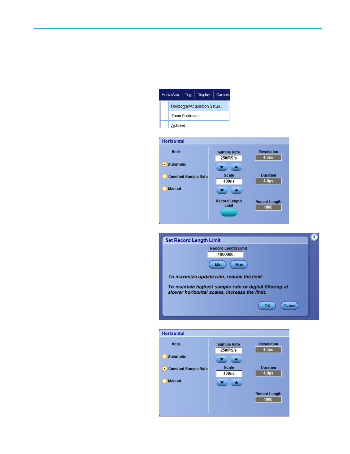
Acquisition
Selecting the horizontal mode
Your instrument has three horizontal modes. Automatic is the default mode. Select the horizontal mode that works best for your
test setup.
To set the horizontal mode, select Horiz/Acq
> Horizontal/Acquisition Setup to display the
horizontal control window. Choose one of the
modes described below.
In Automatic mode you can set the Scale and
Sample Rate. Record length is a dependent
variable. If changing the scale would cause the
record length to exceed the Record Length
Limit, the sample rate is decreased to the next
available setting.
If the sampling mode is real time and the
sample rate is at the real time limit, attempting
to increase the sample rate has no effect.
To set the Record Length Limit, click Record
Length Limit and set the limit using the
buttons or keypad. The default maximum limit
depends on your instrument model and record
length option.
In Constant Sample Rate mode you can set
the Sample Rate and Scale. The default
sample rate ensures bandwidth filter
operation. Record length is a dependent
variable. The maximum record length depends
on your instrument model and record length
option.
The Auxiliary Front Panel resolution knob
changes the sample rate in both automatic
and constant sample rate modes.
DPO70000SX Series User 61
Page 82

Acquisition
In Manual mode you can set the Sample Rate
and Record Length. Horizontal Scale is a
dependent variable calculated from the sample
rate and record length.
The Horizontal Scale knob changes record
length in manual mode.
All three modes interact with sample rate,
scale, and record length as shown. The
horizontal line is the maximum real-time
sample rate. Each staircase shows that as you
increase the scale, the sample rate must
decrease when either the maximum record
length or the record length limit you set is
reached. Manual mode uses the maximum
record length.
Automatic and Constant Sample Rate modes
are identical. However, Constant Sample Rate
mode keeps the sample rate constant at a rate
that guarantees bandwidth enhancement
filters are used.
62 DPO70000SX Series User
Page 83

Acquisition
Using FastAcq
Fast acquisition mode reduces the dead time between waveform acquisitions, enabling the capture and display of transient
events such as glitches or runt pulses. Fast acquisition mode can also display waveform phenomena at an intensity that reflects
their rate-of-occurrence. FastAcq is not available on ATI channels and on some instrument configurations.
1. Push FastAcq on the optional front
pannel or select Horiz/Acq > Fast
Acquisition.
2. Find glitches, transients, or other random
events.
When you have identified an anomaly,
set the trigger system up to look for it.
See Capturing intermittent anomalies on
page 179.
Quick tips
■
To optimize for capturing details or rare events, select Horiz/Acq > Horizontal/Acquisition Setup > Acquisition> Fast
Acq, and then select Optimize For Capturing Details or Capturing rare events.
DPO70000SX Series User 63
Page 84

Acquisition
Using DSP enhanced bandwidth
If your instrument has the enhanced bandwidth feature, use the DSP (digital signal processing) enhanced bandwidth for more
accurate rise time measurements, to extend the bandwidth, and flatten the passband at the full sample rate. The enhanced
bandwidth provides a matched response across enabled channels so you can perform channel-to-channel comparison and
differential measurements.
1. Use AUTOSET to set the horizontal,
vertical, and trigger controls or set the
controls manually.
2. Select Vertical > Bandwidth
Enhanced....
64 DPO70000SX Series User
Page 85

Acquisition
3. Click Digital Filters (DSP) Enabled to
turn the enhanced bandwidth on. You
must set the sample rate correctly to
enable DSP.
4. To force a constant sample rate that
enables DSP filters, check Force
Constant Sample Rate.
NOTE. If not already set, selecting
Constant Sample rate sets the horizontal
mode to constant sample rate, sets the
sample rate to allow DSP, and selects a
DSP bandwidth.
5. Select the desired bandwidth from the
Bandwidth list.
The available bandwidth selections
depend on your instrument, probe, and
probe tip.
Selecting Analog Only selects a hardware
(HW) bandwidth.
6. To apply your selections to all channels,
check Apply To All Channels.
When different probing makes it
impossible for the instrument to set all
channels the same, the instrument sets
each channel to the closest bandwidth
value possible.
The bandwidth indicator appears in the vertical
readout when the enhanced bandwidth is
turned on.
Quick tips
■
Right click the waveform handle to display a menu where you can select the channel bandwidth and other bandwidth
enhanced settings.
■
The DSP enhanced bandwidth occurs at maximum sample rate.
■
Use the DSP enhanced bandwidth when your signals have rise times less than 50 ps.
■
Select Analog Only for higher waveform throughput, overdriven signals, and when you prefer to use your own DSP postprocessing.
■
You can limit the instrument bandwidth by selecting Vertical > Bandwidth Limit and then selecting the bandwidth.
DPO70000SX Series User 65
Page 86

Acquisition
Setting the termination voltage
Oscilloscope inputs have traditionally been terminated to ground. The signals being measured often are not ground referenced.
Pulling signals to ground can impair measurement results or potentially damage the DUT. Termination voltage is available on
TekConnect channels, but not ATI channels.
The instrument delivers a variable termination voltage up to ±3.5 volts to the device under test (DUT), and supports a large offset
range. This allows you to adjust the oscilloscope to mirror the conditions and behavior of the DUT, and measure high-speed
signals in an environment similar to the one in which they operate.
Using the combination of termination voltage and offset to center the oscilloscope reference point in the operating range of the
DUT maximizes the available dynamic range and minimizes the noise of the measurement system.
To set the termination voltage of a channel, do these steps:
1. Select Vertical > Vertical Setup.
2. Click in the Termination Voltage field.
Set the termination voltage using the
keypad or multipurpose knobs.
66 DPO70000SX Series User
Page 87

Acquisition
Using roll mode
Roll mode gives a display similar to a strip chart recorder for low-frequency signals. Roll mode displays acquired data points
without waiting for the acquisition of a complete waveform record.
1. Select Horiz/Acq > Horizontal/
Acquisition Setup....
2. If not selected, click the Acquisition tab.
Click Auto to turn on Roll mode.
NOTE. Roll mode requires Sample, Peak
Detect, or Hi Res acquisition mode.
3. To stop acquisitions in Roll mode:
■
If you are not in Single Sequence,
select Horiz/Acq > Run/Stop and
then click Run/Stop or push RUN/
STOP on the Auxiliary Front Panel
to stop Roll mode.
■
If you are in Single Sequence, Roll
mode acquisitions stop automatically
when a complete record is acquired.
Quick tips
■
Switching to Envelope, Average, or WfmDB acquisition mode will turn off Roll mode.
■
Roll mode is disabled when you set the horizontal scale to 50 ms per division or faster.
■
Roll mode is disabled when using a multi-unit configuration.
DPO70000SX Series User 67
Page 88

Acquisition
Setting up a bus
You can set up serial (optional) and parallel buses.
1. Select Vertical > Bus Setup.
2. Select the Config tab.
3. Scroll to, and then select the bus to set
up.
4. To toggle the display of the bus on or off,
click the Bus button.
5. To change the default label of the bus,
click Label and enter a new label using
the keyboard.
6. To change the displayed position of the
bus, click Bus Position and use the
keyboard or multipurpose knob to enter a
new bus position.
68 DPO70000SX Series User
Page 89

Acquisition
7. To select the bus type, click Bus Type
Serial or Parallel.
You can set up each bus type.
See Set up a serial bus on page 70. or
See Set up a parallel bus on page 71.
Quick tips
■
Position a bus or waveform by clicking on the bus or waveform handle and dragging the handle to the desired position.
DPO70000SX Series User 69
Page 90

Acquisition
Set up a serial bus
You can set serial (optional) bus parameters.
1. To set up a serial bus, select Bus Type
Serial and select the type of serial bus
from the drop-down list.
Each bus type has its own collection of
parameters that you set up. Set up other
bus types as appropriate for the selected
bus.
See the online help for additional help
setting up a bus.
2. To select the input for the displayed
components of the bus, click the
component Input and select from the
displayed list.
3. To set an input threshold, double click
Threshold and enter the threshold using
the keypad.
NOTE. To set thresholds independently
when they are currently shared, go to
Trig > A Event (Main) Trigger Setup
and change Settings to Independent.
4. To select the polarity for the displayed
components of the bus, click the
component Polarity and select from the
displayed list.
Quick tips
■
To use a custom serial decoder, see the online help.
70 DPO70000SX Series User
Page 91
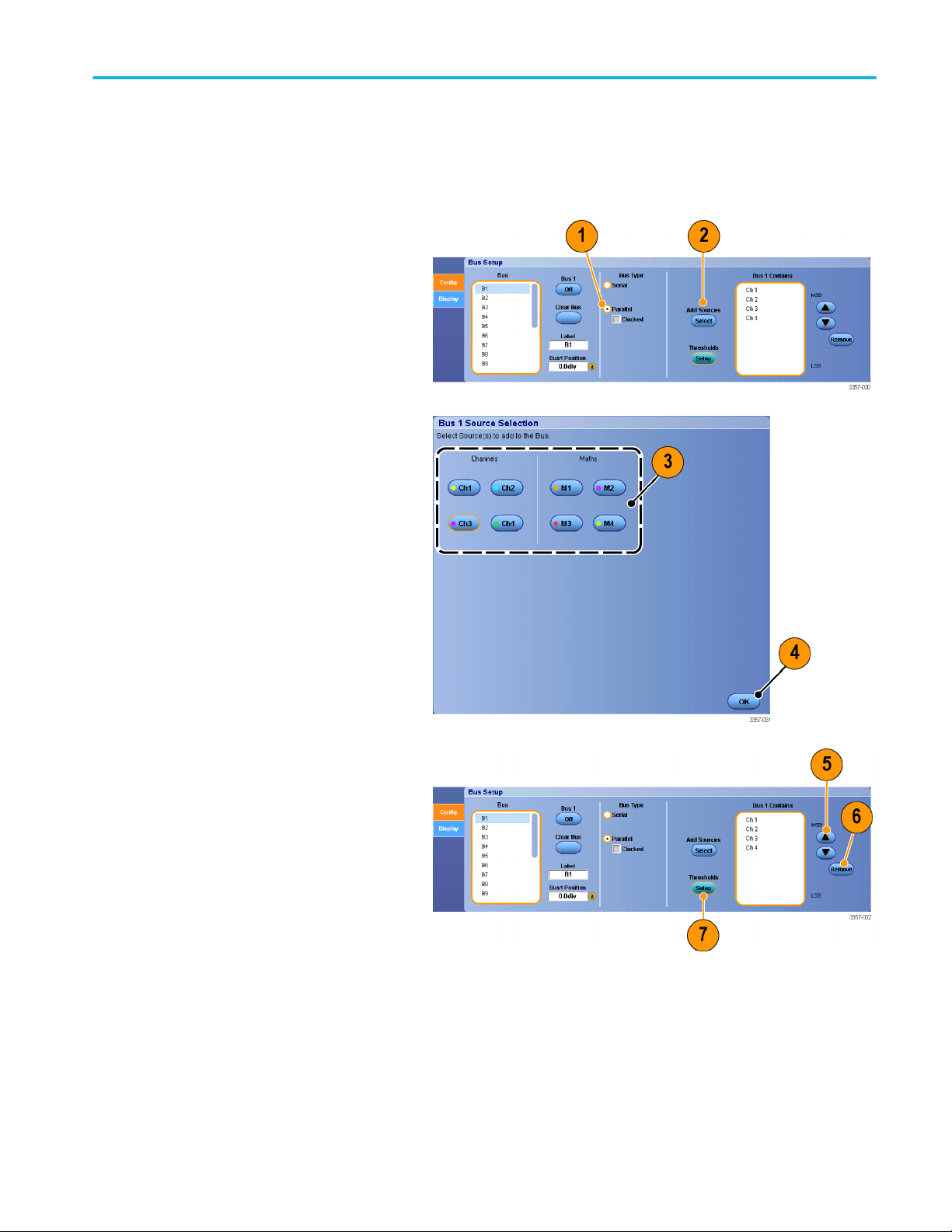
Acquisition
Set up a parallel bus
You can set parallel bus parameters.
1. To set up a parallel bus, select Bus Type
Parallel.
See the online help for additional help
setting up a bus.
2. To add sources to the bus, click the Add
Sources Select button.
3. Click the button for each channel you
want in the bus. The order of the parallel
bus is determined by the order in which
you select the channels.
4. Click the OK button.
5. To move a channel within the bus, scroll
to and select the channel you want to
move, and then click the up or down
arrow buttons.
6. To remove a channel within the bus,
scroll to and select the channel you want
to remove, and then click the Remove
button.
7. To set channel thresholds, click the
Thresholds Setup button.
DPO70000SX Series User 71
Page 92

Acquisition
8. For each threshold you want to set,
double click the channel Threshold, and
enter the threshold using the keypad or
multipurpose knobs on the optional
Auxiliary Front Panel.
9. When the desired thresholds have been
set, click the OK button.
10. To set the clock source and polarity,
double click the item and select from the
displayed list. To set the clock level,
double click the Clock Level, and enter
the level using the keypad or
multipurpose knobs on the optional
Auxiliary Front Panel.
72 DPO70000SX Series User
Page 93

Acquisition
Set up bus display
You can set the bus style and decoding.
1. Select Vertical > Bus Setup.
2. Select the Display tab.
3. To select the bus, scroll to display the
bus, and then select the bus.
4. Select the decoding from the bus
decoding list.
See the online help for information on the
Results Table.
5. Click a + box to expand (display
additional) the views, or click a - box to
collapse (remove) views.
6. Bus views may also be added or
removed from the display by clicking on
the + box or - box in the display. Available
views may include Transaction/transport,
link/framing/packets, physical/bytes/
symbols, and bit level.
DPO70000SX Series User 73
Page 94
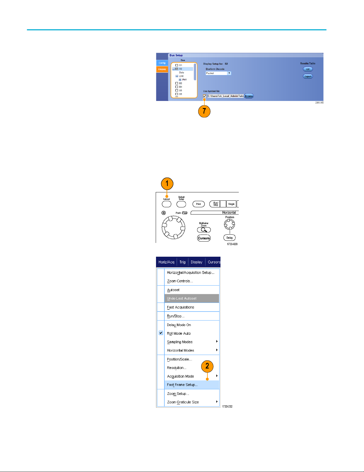
Acquisition
7. If using a symbol table, check Use
Symbol File. Click Browse and browse
to the symbol table file.
For some buses other settings are
available. Set the other settings as
appropriate for your bus.
See the online help for additional help
setting up a bus.
Using FastFrame mode
FastFrame allows you to capture many trigger events as single records in a larger record, and then view and measure each
record individually. Time Stamps display the absolute trigger time for a specific frame and the relative time between triggers of
two specified frames.
1. Use AUTOSET to set the horizontal,
vertical, and trigger controls or set the
controls manually.
2. Select Horiz/Acq > FastFrame Setup....
74 DPO70000SX Series User
Page 95

Acquisition
3. Push FastFrame to toggle it On.
4. Select Frame Size and # of Events
Frames. Then use the multipurpose
knobs to set each one. Number of frames
represents the number of trigger events
that are captured. Frame size is the
number of samples that are stored with
each trigger event (or frame). The
number of frames is reduced if there is
insufficient memory to store all the
records. The shorter the frame length, the
more frames you can acquire.
5. Use the Frame Viewing controls to select
the frame that you want to view.
6. To view multiple frames superimposed
over each other, select Overlay.
7. Use the Time Stamps controls to select
the source for, and frame number of, the
reference frame. The reference frame is
the starting point when measuring the
relative time between two frames.
Quick tips
■
Use FastFrame when you want to preserve the data associated with each trigger event for further analysis or visual
inspections.
■
Use FastFrame when you want to capture multiple events that have long dead times between them that are of no interest to
you.
■
Multiple frames are best viewed with the Normal, Green, or Gray color palettes because the dark blue selected frame may
be hard to distinguish if you use Temp or Spectral.
DPO70000SX Series User 75
Page 96

Acquisition
■
If you select an Average Summary Frame, you can set Math functions (Averaging) to apply to All Frames or have it apply to
Only the Summary Frame. If the summary data is of primary interest, selecting Summary Frame Only can substantially
improve system throughput.
Using FastFrame frame finder
Frame finder allows you to find a FastFrame frame that is different from other frames.
1. Select the source of the FastFrame
frames.
2. Set the Search Range by entering the
From Frame # and the To Frame #.
3. Stop acquisitions by selecting Horiz/Acq
> Run/Stop and clicking Run/Stop or by
pushing Run/Stop on the Auxiliary Front
Panel.
4. Push Start to start the search.
76 DPO70000SX Series User
Page 97

Acquisition
Frame Finder searches for and displays a
different frame.
5. If the anomaly you are looking for is not in
the displayed frame, push No. Frame
Finder searches for another different
frame.
6. If the anomaly you are looking for is in the
displayed frame, push Yes.
7. If you are done searching, push Stop.
8. Select Horiz/Acq > Run/Stop and click
Run/Stop or push Run/Stop on the
Auxiliary Front Panel to restart
acquisitions.
DPO70000SX Series User 77
Page 98

Acquisition
78 DPO70000SX Series User
Page 99

Pinpoint triggers
The Pinpoint trigger system comes with advanced trigger types that are usable on both A and B triggers, and it can reset the
trigger sequence if the B event does not occur after a specific number of events or a specific time. Pinpoint triggers support
capture of events based on the most complex trigger event or sequence of trigger events.
This section contains concepts and procedures for using the trigger system.
Triggering concepts
Trigger event
The trigger event establishes the time-zero point in the waveform record. All waveform record data are located in time with
respect to that point. The instrument continuously acquires and retains enough sample points to fill the pretrigger part of the
waveform record. When a trigger event occurs, the instrument starts acquiring samples to build the posttrigger part of the
waveform record (displayed after, or to the right of, the trigger event). Once a trigger is recognized, the instrument will not accept
another trigger until the acquisition is complete and the holdoff time has expired.
Trigger modes
The trigger mode determines how the instrument behaves in the absence of a trigger event:
■
Normal trigger mode enables the instrument to acquire a waveform only when it is triggered. If no trigger occurs, the last
waveform record acquired remains on the display. If no last waveform exists, no waveform is displayed.
■
Auto trigger mode enables the instrument to acquire a waveform even if a trigger does not occur. Auto mode uses a timer
that starts after a trigger event occurs. If another trigger event is not detected before the timer times out, the instrument
forces a trigger. The length of time it waits for a trigger event depends on the time base setting.
Auto mode, when forcing triggers in the absence of valid triggering events, does not synchronize the waveform on the display.
The waveform will appear to roll across the screen. If valid triggers occur, the display will become stable.
In edge-trigger mode, force the instrument to trigger by pushing the Force Trigger button on the Trigger Setup control window.
Select the trigger mode in the Trig > Mode menu. For more information, see the instrument online help.
Trigger holdoff
Trigger holdoff can help stabilize triggering, by extending the period in which further trigger recognition is suppressed after
initiating an acquisition. Such an extension can help the system skip over the remaining events of a recurring burst of events, and
thus always trigger on the first event in each burst. Adjust holdoff to obtain stable triggering when the instrument is triggering on
undesired trigger events.
Set the trigger holdoff in the Trig > Holdoff menu. For more information, see the instrument online help.
DPO70000SX Series User
79
Page 100

Pinpoint triggers
Trigger coupling
Trigger coupling determines what part of the signal is passed to the trigger circuit. Edge triggering can use all available coupling
types: AC, DC, Low Frequency Rejection, High Frequency Rejection, Noise Rejection, and RF coupling. All other trigger types
use DC coupling only. Your instrument may not offer all coupling types.
Select the trigger coupling in the Trig > A Event (Main) Trigger Setup menu. For more information, see the instrument online
help.
Horizontal position
Horizontal position defines where the trigger occurs on the waveform record. It lets you choose how much the instrument
acquires before and after the trigger event. The part of the record that occurs before the trigger is the pretrigger part. The part
that occurs after the trigger is the posttrigger part.
Pretrigger data is valuable when troubleshooting. For example, if you are trying to find the cause of an unwanted glitch in your
test circuit, trigger on the glitch and make the pretrigger period large enough to capture data before the glitch. By analyzing what
happens before the glitch, you may uncover information that helps you find the source of the glitch. Alternatively, to see what is
happening in your system as a result of the trigger event, make the posttrigger period large enough to capture data after the
trigger.
Slope and level
The slope control determines whether the instrument finds the trigger point on the rising or the falling edge of a signal. The level
control determines where on that edge the trigger point occurs.
Delayed trigger system
You can trigger with the A (Main) trigger system alone or combine the A (Main) trigger with the B (Delayed) trigger to trigger on
sequential events. When using sequential triggering, the A trigger event arms the trigger system, and the B trigger event triggers
the instrument when the B trigger conditions are met. A and B triggers can (and typically do) have separate sources. The B
trigger condition is based on a time delay or a specified number of events. See Using A (Main) and B (Delayed) triggers on
page 85.
80 DPO70000SX Series User
 Loading...