

Page 1

MSO70000C/DX,
DPO70000C/DX, DPO7000C,
MSO5000/B, and DPO5000/B
Series Oscilloscopes
Specifications and Performance Verification
Technical Reference
*P077006314*
077-0063-14
Page 2

Page 3

MSO70000C/DX,
DPO70000C/DX, DPO7000C,
MSO5000/B, and DPO5000/B
Series Oscilloscopes
Specifications and Performance Verification
Technical Reference
Warning
The servicing instructions are for use by qualified personnel only. To avoid
personal injury, do not perform any servicing unless you are qualified to do
so. Refer to all safety summaries prior to performing service.
This document supports product firmware version 6.8.0 and above.
Revision B
www.tek.com
077-0063-14
Page 4

Copyright © Tektronix. All rights reserved. Licensed software products are owned by Tektronix or its subsidiaries
or suppliers, and are protected by national copyright laws and international treaty provisions. Tektronix products
are covered by U.S. and foreign patents, issued and pending. Information in this publication supersedes that in all
previously published material. Specifications and price change privileges reserved.
TEKTRONIX and TEK are registered trademarks of Tektronix, Inc.
Pinpoint, TekLink, and RT-Eye are registered trademarks of Tektronix, Inc.
Contacting Tektronix
Tektronix, Inc.
14150 SW Karl Braun Drive
P.O. Box 500
Beaverton, OR 97077
USA
For product information, sales, service, and technical support:
■
In North America, call 1-800-833-9200.
■
Worldwide, visit www.tek.com to find contacts in your area.
Page 5

Warranty
Tektronix warrants that this product will be free from defects in materials and workmanship for a period of one
(1) year from the date of shipment. If any such product proves defective during this warranty period, Tektronix, at
its option, either will repair the defective product without charge for parts and labor, or will provide a replacement
in exchange for the defective product. Parts, modules and replacement products used by Tektronix for warranty
work may be new or reconditioned to like new performance. All replaced parts, modules and products become the
property of Tektronix.
In order to obtain service under this warranty, Customer must notify Tektronix of the defect before the expiration
of the warranty period and make suitable arrangements for the performance of service. Customer shall be
responsible for packaging and shipping the defective product to the service center designated by Tektronix, with
shipping charges prepaid. Tektronix shall pay for the return of the product to Customer if the shipment is to a
location within the country in which the Tektronix service center is located. Customer shall be responsible for
paying all shipping charges, duties, taxes, and any other charges for products returned to any other locations.
This warranty shall not apply to any defect, failure or damage caused by improper use or improper or inadequate
maintenance and care. Tektronix shall not be obligated to furnish service under this warranty a) to repair damage
resulting from attempts by personnel other than Tektronix representatives to install, repair or service the product;
b) to repair damage resulting from improper use or connection to incompatible equipment; c) to repair any
damage or malfunction caused by the use of non-Tektronix supplies; or d) to service a product that has been
modified or integrated with other products when the effect of such modification or integration increases the time
or difficulty of servicing the product.
THIS WARRANTY IS GIVEN BY TEKTRONIX WITH RESPECT TO THE PRODUCT IN LIEU OF ANY
OTHER WARRANTIES, EXPRESS OR IMPLIED. TEKTRONIX AND ITS VENDORS DISCLAIM ANY
IMPLIED WARRANTIES OF MERCHANTABILITY OR FITNESS FOR A PARTICULAR PURPOSE.
TEKTRONIX' RESPONSIBILITY TO REPAIR OR REPLACE DEFECTIVE PRODUCTS IS THE SOLE AND
EXCLUSIVE REMEDY PROVIDED TO THE CUSTOMER FOR BREACH OF THIS WARRANTY.
TEKTRONIX AND ITS VENDORS WILL NOT BE LIABLE FOR ANY INDIRECT, SPECIAL,
INCIDENTAL, OR CONSEQUENTIAL DAMAGES IRRESPECTIVE OF WHETHER TEKTRONIX OR THE
VENDOR HAS ADVANCE NOTICE OF THE POSSIBILITY OF SUCH DAMAGES.
[W2 – 15AUG04]
Page 6

Page 7

Table of Contents
Important safety information .............................................................................................................. iii
General safety summary ................................................................................................................ iii
Terms in the manual ...................................................................................................................... vi
Terms on the product ..................................................................................................................... vi
Symbols on the product ................................................................................................................. vi
Specifications (MSO70000C/DX, DPO70000C/DX, and DPO7000C series)
Vertical system analog channels ..................................................................................................... 2
Horizontal and acquisition system ................................................................................................ 48
Trigger specifications ................................................................................................................... 58
Serial trigger specifications .......................................................................................................... 65
Digital acquisition specifications .................................................................................................. 68
Input-output port specifications .................................................................................................... 70
Data storage specifications ........................................................................................................... 73
Power source specification ........................................................................................................... 74
Mechanical specifications ............................................................................................................. 74
Environmental specifications ....................................................................................................... 76
Specifications (MSO/DPO5000/B Series)
Analog channel input and vertical specification ........................................................................... 77
Horizontal and acquisition system specifications ......................................................................... 86
Trigger specifications ................................................................................................................... 88
Digital acquisition specifications MSO5000/B series .................................................................. 93
P6616 digital probe specifications ................................................................................................ 93
Display specificationsContainer ................................................................................................... 94
Input-Output port specifications ................................................................................................... 94
Data storage specifications ........................................................................................................... 96
Power source specifications .......................................................................................................... 96
Environmental specifications ....................................................................................................... 97
Mechanical specifications ............................................................................................................. 98
Performance verification (MSO/DPO70000C, MSO/DPO70000DX, and
DPO7000C series)
Performance verification (MSO/DPO70000C, MSO/DPO70000DX, and DPO7000C series) ... 99
Conventions ........................................................................................................................... 100
MSO70000C/DX, DPO70000C/DX, DPO7000C, MSO5000/B, DPO5000/B Series i
Page 8

Table of Contents
Brief procedures (MSO/DPO70000C, MSO/DPO70000DX, and DPO7000C series) .............. 102
Self tests ................................................................................................................................ 102
Functional tests ...................................................................................................................... 103
Performance tests (MSO/DPO70000C, MSO/DPO70000DX, and DPO7000C series) ............ 115
Prerequisites .......................................................................................................................... 116
Equipment required ............................................................................................................... 116
Test record ............................................................................................................................. 121
Signal acquisition system checks .......................................................................................... 176
Time base system checks ...................................................................................................... 241
Trigger system checks ................................................................................................................ 253
Check time qualified trigger accuracy ........................................................................................ 253
Check sensitivity edge trigger DC coupled ................................................................................ 257
Output signal checks ................................................................................................................... 265
Check aux trigger out ................................................................................................................. 266
Check probe compensation or fast edge output .......................................................................... 268
Serial trigger checks (Optional on some models) ....................................................................... 271
Check serial trigger baud rate limits ........................................................................................... 271
Check serial trigger clock recovery range <4 GHz models ........................................................ 277
Sine wave generator leveling procedure ..................................................................................... 281
Method 1 ..................................................................................................................................... 281
Method 2 ..................................................................................................................................... 283
Performance verification (MSO/DPO5000/B series)
Performance verification (MSO/DPO5000/B series) ................................................................. 285
Test record .................................................................................................................................. 286
Performance tests (MSO/DPO5000-B series) ............................................................................ 316
Prerequisites ................................................................................................................................ 316
Self test ....................................................................................................................................... 317
Check input impedance (Resistance) .......................................................................................... 318
Check DC balance ...................................................................................................................... 319
Check DC gain accuracy ............................................................................................................ 321
Check offset accuracy ................................................................................................................. 323
Check analog bandwidth ............................................................................................................ 326
Check random noise sample acquisition mode ........................................................................... 329
Check sample rate and delay time accuracy ............................................................................... 330
Check delta time measurement accuracy .................................................................................... 332
Check digital threshold accuracy (MSO5000/B only) ............................................................... 334
Check trigger out ........................................................................................................................ 337
ii MSO70000C/DX, DPO70000C/DX, DPO7000C, MSO5000/B, DPO5000/B Series
Page 9

Important safety information
This manual contains information and warnings that must be followed by the user
for safe operation and to keep the product in a safe condition.
General safety summary
Use the product only as specified. Review the following safety precautions to
avoid injury and prevent damage to this product or any products connected to it.
Carefully read all instructions. Retain these instructions for future reference.
Comply with local and national safety codes.
For correct and safe operation of the product, it is essential that you follow
generally accepted safety procedures in addition to the safety precautions
specified in this manual.
The product is designed to be used by trained personnel only.
Only qualified personnel who are aware of the hazards involved should remove
the cover for repair, maintenance, or adjustment.
Before use, always check the product with a known source to be sure it is
operating correctly.
This product is not intended for detection of hazardous voltages.
Use personal protective equipment to prevent shock and arc blast injury where
hazardous live conductors are exposed.
MSO70000C/DX, DPO70000C/DX, DPO7000C, MSO5000/B, DPO5000/B Series iii
Page 10

Important safety information
To avoid fire or personal
injury
Use proper power cord. Use only the power cord specified for this product and
certified for the country of use. Do not use the provided power cord for other
products.
Ground the product. This product is grounded through the grounding conductor of
the power cord. To avoid electric shock, the grounding conductor must be
connected to earth ground. Before making connections to the input or output
terminals of the product, ensure that the product is properly grounded. Do not
disable the power cord grounding connection.
Power disconnect. The power cord disconnects the product from the power
source. See instructions for the location. Do not position the equipment so that it
is difficult to operate the power cord; it must remain accessible to the user at all
times to allow for quick disconnection if needed.
Connect and disconnect properly. Do not connect or disconnect probes or test
leads while they are connected to a voltage source. Use only insulated voltage
probes, test leads, and adapters supplied with the product, or indicated by
Tektronix to be suitable for the product.
Observe all terminal ratings. To avoid fire or shock hazard, observe all rating and
markings on the product. Consult the product manual for further ratings
information before making connections to the product. Do not exceed the
Measurement Category (CAT) rating and voltage or current rating of the lowest
rated individual component of a product, probe, or accessory. Use caution when
using 1:1 test leads because the probe tip voltage is directly transmitted to the
product.
Do not apply a potential to any terminal, including the common terminal, that
exceeds the maximum rating of that terminal.
Do not operate without covers. Do not operate this product with covers or panels
removed, or with the case open. Hazardous voltage exposure is possible.
Avoid exposed circuitry. Do not touch exposed connections and components when
power is present.
Do not operate with suspected failures. If you suspect that there is damage to this
product, have it inspected by qualified service personnel.
Disable the product if it is damaged. Do not use the product if it is damaged or
operates incorrectly. If in doubt about safety of the product, turn it off and
disconnect the power cord. Clearly mark the product to prevent its further
operation.
Before use, inspect voltage probes, test leads, and accessories for mechanical
damage and replace when damaged. Do not use probes or test leads if they are
damaged, if there is exposed metal, or if a wear indicator shows.
Examine the exterior of the product before you use it. Look for cracks or missing
pieces.
Use only specified replacement parts.
Do not operate in wet/damp conditions. Be aware that condensation may occur if a
unit is moved from a cold to a warm environment.
Do not operate in an explosive atmosphere.
iv MSO70000C/DX, DPO70000C/DX, DPO7000C, MSO5000/B, DPO5000/B Series
Page 11

Important safety information
Keep product surfaces clean and dry. Remove the input signals before you clean
the product.
Provide proper ventilation. Refer to the manual's installation instructions for
details on installing the product so it has proper ventilation.
Slots and openings are provided for ventilation and should never be covered or
otherwise obstructed. Do not push objects into any of the openings.
Provide a safe working environment. Always place the product in a location
convenient for viewing the display and indicators.
Avoid improper or prolonged use of keyboards, pointers, and button pads.
Improper or prolonged keyboard or pointer use may result in serious injury.
Be sure your work area meets applicable ergonomic standards. Consult with an
ergonomics professional to avoid stress injuries.
Use care when lifting and carrying the product. This product is provided with
handles for lifting and carrying.
WARNING. The product is heavy. To reduce the risk of personal injury or damage
to the device get help when lifting or carrying the product.
Probes and test leads
Use only the Tektronix rackmount hardware specified for this product.
Before connecting probes or test leads, connect the power cord from the power
connector to a properly grounded power outlet.
Keep fingers behind the finger guards on the probes.
Remove all probes, test leads and accessories that are not in use.
Use only correct Measurement Category (CAT), voltage, temperature, altitude,
and amperage rated probes, test leads, and adapters for any measurement.
MSO70000C/DX, DPO70000C/DX, DPO7000C, MSO5000/B, DPO5000/B Series v
Page 12
Important safety information
Terms in the manual
Terms on the product
These terms may appear in this manual:
WARNING. Warning statements identify conditions or practices that could result
in injury or loss of life.
CAUTION. Caution statements identify conditions or practices that could result in
damage to this product or other property.
These terms may appear on the product:
■
DANGER indicates an injury hazard immediately accessible as you read the
marking.
Symbols on the product
■
WARNING indicates an injury hazard not immediately accessible as you
read the marking.
■
CAUTION indicates a hazard to property including the product.
When this symbol is marked on the product, be sure to consult the
manual to find out the nature of the potential hazards and any actions
which have to be taken to avoid them. (This symbol may also be used
to refer the user to ratings in the manual.)
The following symbols may appear on the product:
vi MSO70000C/DX, DPO70000C/DX, DPO7000C, MSO5000/B, DPO5000/B Series
Page 13
Specifications (MSO70000C/DX, DPO70000C/DX, and DPO7000C series)
This chapter contains specifications for the instrument. All specifications are
guaranteed unless noted as "typical." Typical specifications are provided for your
convenience but are not guaranteed. Specifications that are marked with the
symbol are checked in this manual. All specifications apply to all models unless
noted otherwise.
<4 GHz models. Includes the DPO7000C Series instruments unless noted
otherwise.
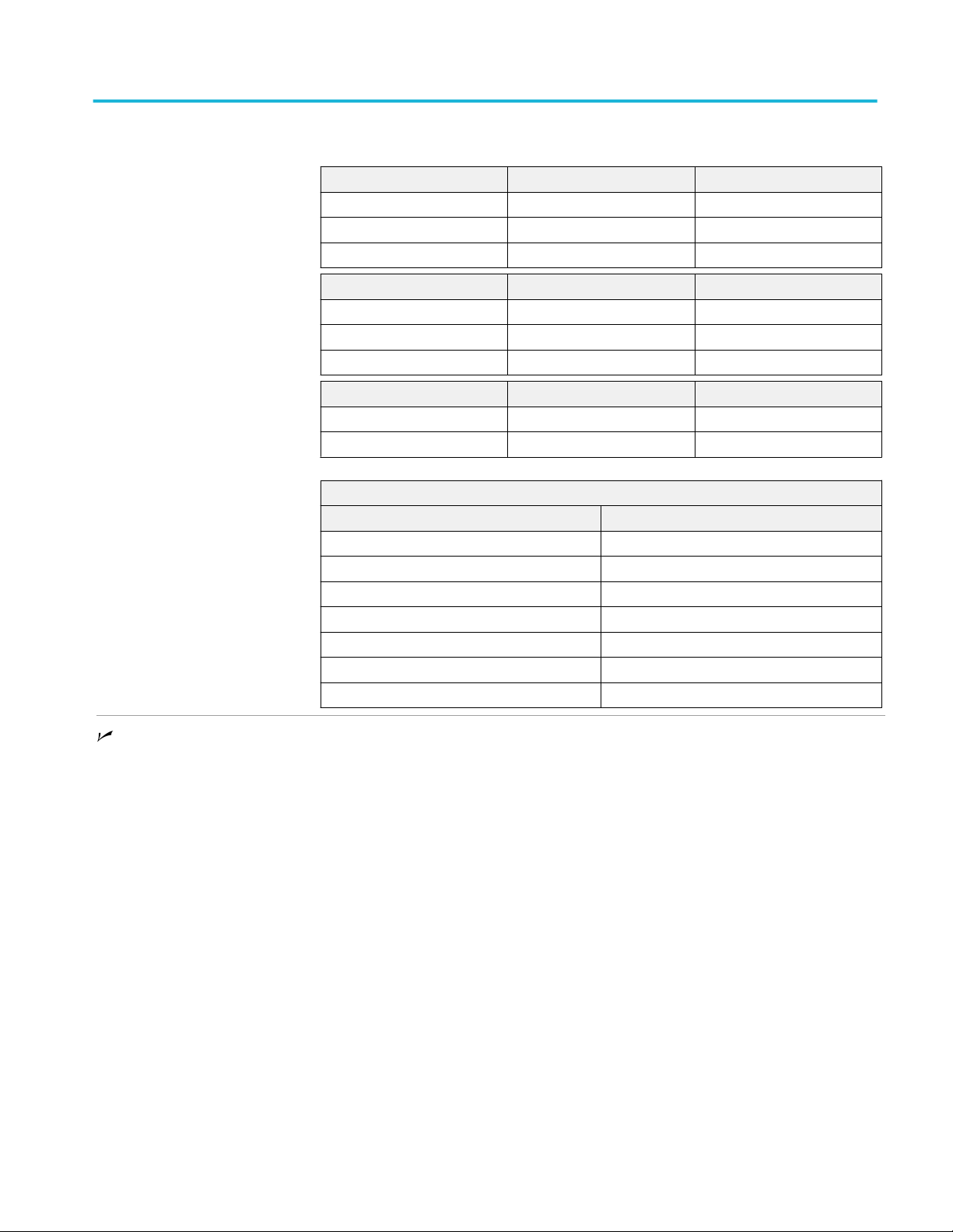
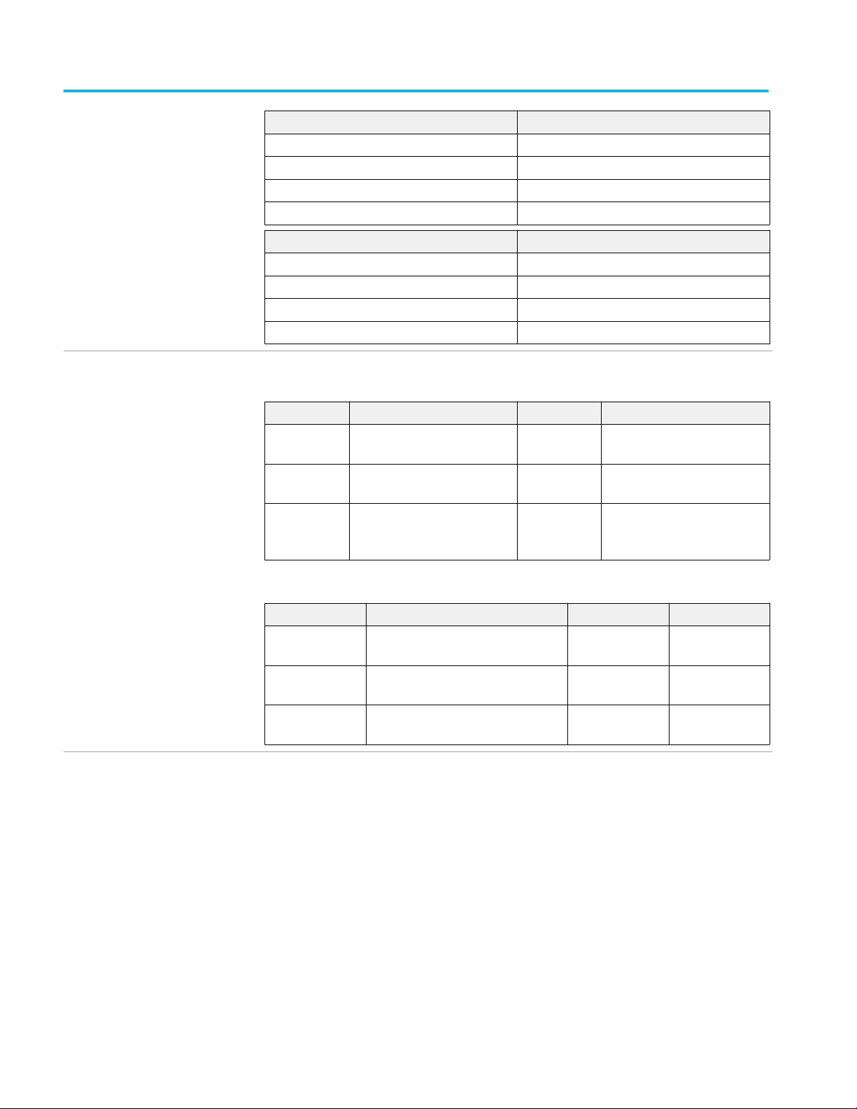
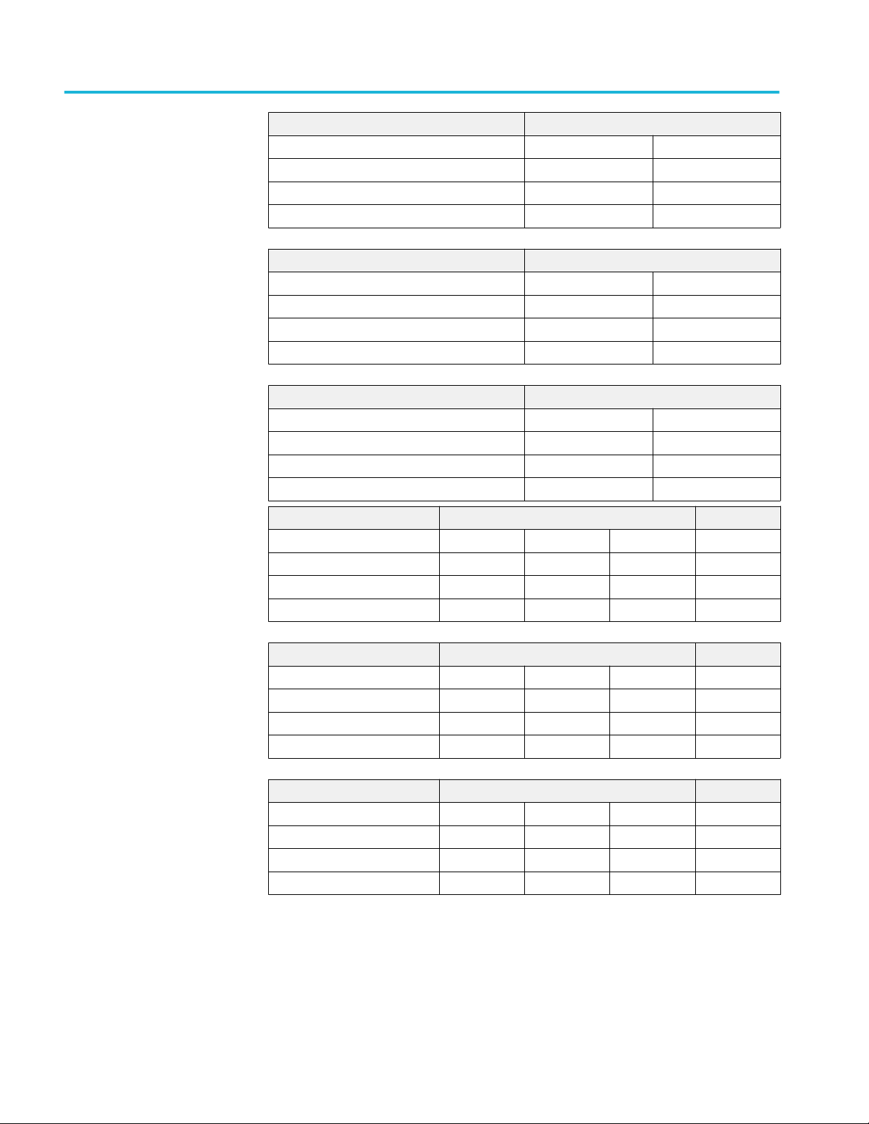
Table 1: Instrument Model Numbers (<4 GHz)
DPO
7354C (3.5 GHz)
7254C (2.5 GHz)
7104C (1 GHz)
7054C (500 MHz)
≥4 GHz, ≤20 GHz models. Includes the MSO70000C and DPO70000C Series
instruments unless noted otherwise.
Table 2: Instrument Model Numbers (≥4 GHz, ≤20 GHz)
MSO DPO
70404C (4 GHz) 70404C (4 GHz)
70604C (6 GHz) 70604C (6 GHz)
70804C (8 GHz) 70804C (8 GHz)
71254C (12.5 GHz) 71254C (12.5 GHz)
71604C (16 GHz) 71604C (16 GHz)
72004C (20 GHz) 72004C (20 GHz)
>20 GHz models. Includes the MSO70000DX and DPO70000DX Series
instruments unless noted otherwise.
Table 3: Instrument Model Numbers (>20 GHz)
MSO DPO
72304DX (23 GHz) 72304DX (23 GHz)
72504DX (25 GHz) 72504DX (25 GHz)
73304DX (33 GHz) 73304DX (33 GHz)
≥4 GHz models. Includes all MSO70000C/DX and DPO70000C/DX Series
instruments.
MSO70000C/DX, DPO70000C/DX, DPO7000C, MSO5000/B, DPO5000/B Series 1
Page 14

Specifications (MSO70000C/DX, DPO70000C/DX, and DPO7000C series)
To meet specifications, two conditions must first be met:
■
The instrument must have been calibrated in an ambient temperature between
18 °C and 28 °C (64 °F and 82 °F).
■
The instrument must be operating within the environmental limits. (See page
1-78.)
■
The instrument must be powered from a source that meets the specifications.
(See page 2-18.)
■
The instrument must have been operating continuously for at least 20 minutes
within the specified operating temperature range. (60 minutes continuous
operation required for the MSO/DPO70000DX instruments if the ambient
relative humidity is greater than 60%.)
■
You must perform the Signal Path Compensation procedure after the warmup period. See the online help for instructions on how to perform signal path
compensation. If the ambient temperature changes more than 5 °C, repeat the
procedure.
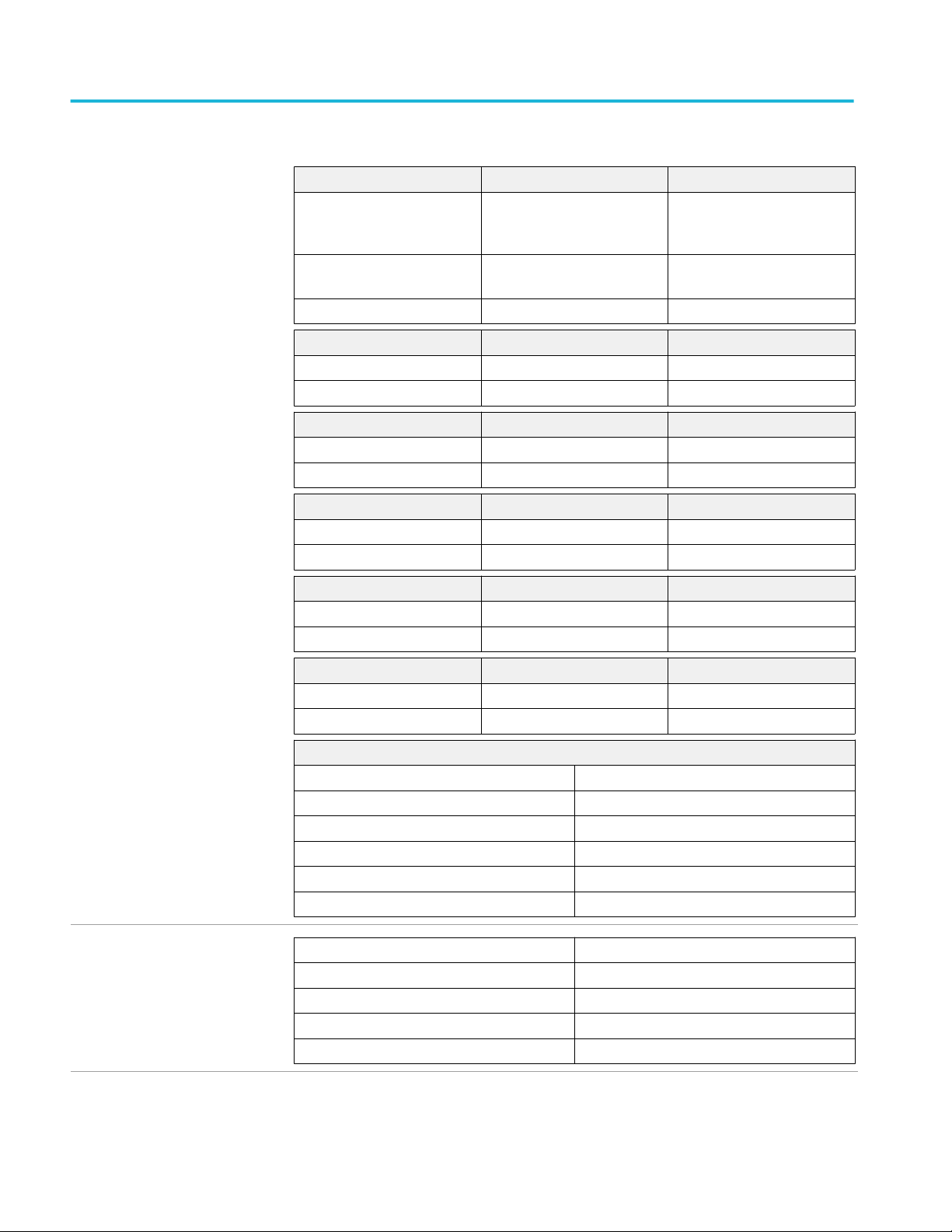
Vertical system analog channels
Number of channels Four channels, all identical
Input connector
≥ 4 GHz models TekConnect. Power supply compatible with VPI.
< 4 GHz models BNC and VPI probe
Input coupling
>20 GHz models DC, 50 Ω to a programmable termination voltage, and GND.
GND coupling disconnects the input connector from all channel input circuitry and connects a
ground reference to the channel input circuitry.
The termination in 50 Ω coupling can be connected to any DC value from –3.5 V to +3.5 V.
≥4 GHz, ≤20 GHz models DC, 50 Ω, and GND. GND coupling disconnects the input connector from all channel input circuitry
and connects a ground reference to the channel input circuitry.
<4 GHz models DC, AC, or GND. GND coupling approximates ground reference by measuring an unused
preamplifier input that has been connected to ground. The signal being measured is not
disconnected from the channel input load.
Input resistance >20 GHz
models
≤1.2 VFS settings 50 Ω ±3% at 18 to 28 ºC (64 to 82 ºF)
50 Ω ±4% over 5 to 45 ºC (45 to 113 ºF), type tested
>1.2 VFS settings 50 Ω ±4.4% over 5 to 45 ºC (45 to 113 ºF), type tested
2 MSO70000C/DX, DPO70000C/DX, DPO7000C, MSO5000/B, DPO5000/B Series
Page 15

Vertical system analog channels (cont.) Specifications (MSO70000C/DX, DPO70000C/DX, and DPO7000C
series)
Input resistance ≥4 GHz
≤20 GHz models
100 mVFS to 995 mVFS: 50 Ω ±1.5% at 25 ºC (77 ºF)
50 Ω ±2% over 10 to 45 ºC (50 to 113 ºF), type tested
1 VFS to 5 VFS: 50 Ω ±2.2 Ω over 10 to 45 ºC (50 to 113 ºF), type tested
Input impedance DC coupled
<4 GHz models
1 MΩ, DC coupled 1 MΩ ± 1% in parallel with 13 pF ± 2 pF
50 Ω, DC coupled 50 Ω ± 1%, typical
Maximum input voltage range
>20 GHz models
≤1.2 VFS settings: ±1.5 V relative to the termination bias (30 mA maximum)
±5 V absolute maximum input
>1.2 VFS settings: 8 V. Limited by maximum Vterm current and the attenuator power rating at maximum temperature.
Maximum input voltage ≥4 GHz
and ≤20 GHz models
<1.0 V/Full Scale settings: ±3.3 V Maximum
≥ 1.0 V/Full Scale settings: ±5.0 V Maximum
Maximum input voltage <4 GHz
models
1 MΩ – DC coupled 150 V. Derate at 20 dB/decade to 9 VRMS above 200 kHz.
1 MΩ – AC coupled, or GND
coupled
50 Ω 5 V RMS, with peaks ≤ ± 24 V
Measurement category for MSODPO70K and DPO7K series only
Input termination voltage (VTerm)
range >20 GHz models
≤1.2 VFS settings: -3.5 V to +3.5 V
>1.2 VFS settings: 0 V
Input termination voltage (VTerm)
range ≤20 GHz models
The maximum input voltage at the BNC, between center conductor and ground is 400 V peak. The
RMS voltage is limited to <150 V for arbitrary waveshapes including DC. The maximum pulse width
for impulses with peaks over 150 V is 50 μs. Example: At 0 V to 400 V peak, rectangular wave, the
duty factor is 14%.
The maximum transient withstand voltage is ± 800 V peak.
The measuring terminals on this product are not rated for connection to mains or Measurement
Category II, III or IV circuits.
0 V
MSO70000C/DX, DPO70000C/DX, DPO7000C, MSO5000/B, DPO5000/B Series 3
Page 16
Specifications (MSO70000C/DX, DPO70000C/DX, and DPO7000C series) Vertical system analog channels
(cont.)
Input VSWR >20 GHz models,
typical
≤1.2 VFS settings: 0 – 17 GHz: 1.4:1
>1.2 VFS settings: 0 – 17 GHz: 1.4:1
Input VSWR ≥4 GHz ≤20 GHz
models
Input VSWR <4 GHz models
Measured with a TekConnect TCA-292D adaptor and a network analyzer.
17 – 20 GHz: 1.6:1
20 – 33 GHz: 2.0:1
17 – 33 GHz: 2.0:1
Measured with a TekConnect SMA adapter and a network analyzer
Input Frequency VSWR < 1 V/Full Scale VSWR ≥ 1 V/Full Scale
<2.5 GHz 1.25:1 1.2:1
<6 GHz 1.5:1 1.2:1
<14 GHz 2.1:1 1.5:1
<15 GHz 2.5:1 1.5:1
<20 GHz 3.2:1 1.9:1
Input Frequency VSWR
<3.5 GHz 3.0:1
<2.5 GHz 2.0:1
<2 GHz 1.5:1
<1 GHz 1.2:1
Number of digitized bits 8 bits
Digitizer nonlinearity, typical < 1.0 DL (digitization level), differential; < 1 DL integral, independently based
Sensitivity range
>20 GHz models, 50 Ω 62.5 mVFS to 6 V
≥4 GHz, ≤20 GHz models,
50 Ω
<4 GHz models, 50 Ω 1 mV/div to 1 V/division, in a 1-2-5 sequence
<4 GHz models, 1 MΩ 1 mV/div to 10 V/division, in a 1-2-5 sequence
DC gain accuracy sample or
average acquisition mode ≥4 GHz
models
DC gain accuracy sample or
average acquisition mode <4 GHz
models
100 mVFS to 5 VFS. Below 100 mVFS, Full Scale (FS) is software zoom.
Fine adjustment available with ≥1% resolution
Fine adjustment available with ≥1% resolution
± 2%
± 1.0% with 0 V net offset
Add 0.5% for ranges <2 mV/div
FS
4 MSO70000C/DX, DPO70000C/DX, DPO7000C, MSO5000/B, DPO5000/B Series
Page 17

Vertical system analog channels (cont.) Specifications (MSO70000C/DX, DPO70000C/DX, and DPO7000C
series)
Add 1.5% x | net offset/Max offset | for ranges <5 mV/div
Add 0.5% x | net offset/Max offset | for ranges ≥ 5 mV/div
Add 0.5% for ranges ≥ 1 V/div in 1 MΩ coupling and with net offset >10 V
DC voltage measurement
accuracy >20 GHz models
DC voltage measurement
accuracy ≥4 GHz ≤20 GHz models
Average acquisition mode
( ≥16 averages)
Delta voltage measurement
between any two averages of
≥16 waveforms acquired under
the same setup and ambient
conditions
Average acquisition mode
( ≥16 averages)
Delta voltage measurement
between any two averages of
≥16 waveforms acquired under
the same setup and ambient
conditions
Gain setting DC measurement accuracy
62.5 mVFS – 1.2 V
FS
±[2% | reading - net offset | +
0.4% | net offset | + 0.2% | net
offset – Vterm setting | +2.5 mV
+ 0.014 FS]
1.21 VFS – 6 V
FS
±[2% | reading - net offset | +
0.4% | net offset | + 12.5 mV +
0.014 FS]
62.5 mVFS – 6 V
FS
±[2% | reading – net offset | +
0.008 FS]
Gain setting DC measurement accuracy
100 mVFS to 995 mV
FS
±[2% | reading – net offset | +
0.35% | net offset | +1.5 mV +
0.014 FS]
1 VFS to 5 V
FS
±[2% | reading – net offset | +
0.35% | net offset | +7.5 mV +
0.014 FS]
100 mVFS to 5 V
FS
±[2% | reading | + 0.008 FS]
DC voltage measurement
accuracy <4 GHz models
Average acquisition mode
DC accuracy (in volts)
Net offset = offset - ( position × volts/division).
±(DC Gain Accuracy × | reading -(net offset) | + offset accuracy + 0.1 division)
( ≥16 averages)
Delta voltage measurement
±(DC Gain Accuracy × | reading | + 0.05 division)
between any two averages of
≥16 waveforms acquired with
the same setup and ambient
conditions
MSO70000C/DX, DPO70000C/DX, DPO7000C, MSO5000/B, DPO5000/B Series 5
Page 18

Specifications (MSO70000C/DX, DPO70000C/DX, and DPO7000C series) Vertical system analog channels
(cont.)
Sample acquisition mode,
typical
Delta voltage measurement
between any two samples
acquired with the same setup
and ambient conditions,
typical
Position range ± 5 divisions
±(DC Gain Accuracy × | reading -(net offset) | + offset accuracy + 0.15 division + 0.6 mV)
±(DC Gain Accuracy × | reading | + 0.15 division + 1.2 mV)
Convert offset, position and the constant offset term to volts by multiplying by the appropriate volts/
div.
Specification applies to any sample and to the High, Low, Max, Min, Mean, Cycle Mean, RMS, and
Cycle RMS measurements. Delta volts specification applies to subtractive calculations involving
two of these measurements. Delta volts specification applies to the Positive Overshoot, Negative
Overshoot, peak-peak, and amplitude measurements.
6 MSO70000C/DX, DPO70000C/DX, DPO7000C, MSO5000/B, DPO5000/B Series
Page 19

Vertical system analog channels (cont.) Specifications (MSO70000C/DX, DPO70000C/DX, and DPO7000C
series)
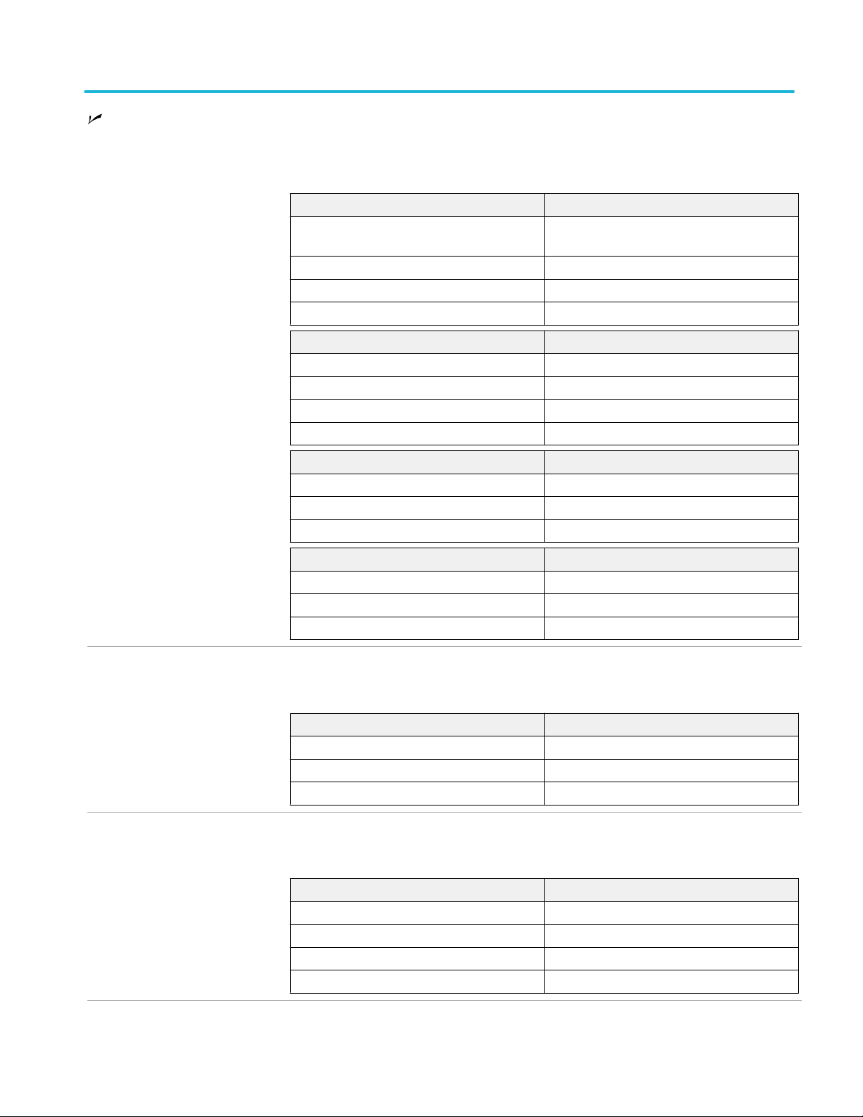
Offset range
>20 GHz models
≥4 GHz, ≤20 GHz models Offset is reduced to allow for position control according to the following formulas:
Full Scale voltage range Offset range
62.5 mVFS – 1.2 V
>1.2 VFS – 6 V
FS
FS
±3.4 V
±6 V
10 mV/div to 99.5 mV/div: Offset range = ±(0.5 V - (V/div setting × 5 div))
100 mV/div to 500 mV/div: Offset range = ±(2.5 V - (V/div setting × 5 div))
SCALE range Offset range
10 mV/div ±0.450 V
12 mV/div ±0.440 V
14 mV/div ±0.430 V
16 mV/div ±0.420 V
18 mV/div ±0.410 V
19.9 mV/div ±0.4005 V
20 mV/div ±0.400 V
30 mV/div ±0.350 V
40 mV/div ±0.300 V
49.8 mV/div ±0.251 V
50 mV/div ±0.250 V
60 mV/div ±0.200 V
70 mV/div ±0.150 V
80 mV/div ±0.100 V
90 mV/div ±0.050 V
99.5 mV/div ±0.0025 V
100 mV/div ±2.00 V
120 mV/div ±1.90 V
140 mV/div ±1.80 V
160 mV/div ±1.70 V
200 mV/div ±1.50 V
248 mV/div ±1.260 V
250 mV/div ±1.250 V
300 mV/div ±1.00 V
400 mV/div ±0.50 V
500 mV/div ±0.00 V
MSO70000C/DX, DPO70000C/DX, DPO7000C, MSO5000/B, DPO5000/B Series 7
Page 20
Specifications (MSO70000C/DX, DPO70000C/DX, and DPO7000C series) Vertical system analog channels
(cont.)
<4 GHz models, 50 Ω coupling
SCALE range Offset range
1 mV/div to 50 mV/div ±1.0 V
50.5 mV/div to 99.5 mV/div ±1.5 V - 10 divisions
100 mV/div to 500 mV/div ±10 V
505 mV/div to 1 V/div ±15 V - 10 divisions
<4 GHz models, 1 MΩ
coupling
SCALE range Offset range
1 mV/div to 50 mV/div ±1 V
50.5 mV/div to 99.5 mV/div ±1.5 V - 10 divisions
100 mV/div to 500 mV/div ±10 V
505 mV/div to 995 mV/div ±15 V - 10 divisions
1.0 V/div to 5 V/div ±100 V
5.05 V/div to 10 V/div ±150 V - 10 divisions
Offset accuracy Net offset = offset - (position × volts/division).
>20 GHz models
Full scale voltage range Offset accuracy
62.5 mVFS to 1.2 V
>1.2 VFS to 6 V
FS
FS
±(0.4% | net offset | + 0.2% | net offset – Vterm
setting | + 2.5 mV + 1% Full Scale)
±(0.6% | net offset | + 13.4 mV + 1% Full Scale)
≥4 GHz, ≤20 GHz models
<4 GHz models
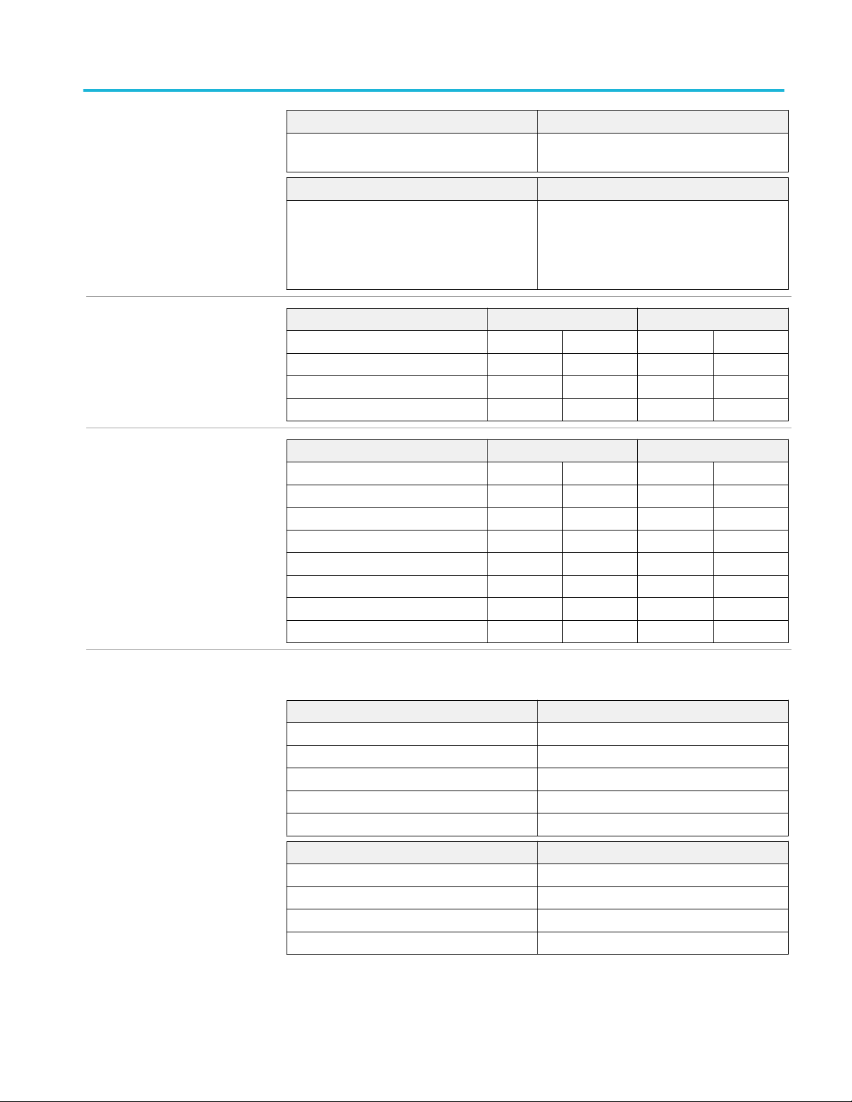
Analog bandwidth >20 GHz
models
SCALE range Offset accuracy Temperature variation
10 mV/div to 99.5 mV/div ±(0.35% × | net offset | +
1.5 mV + 1% x Full Scale)
100 mV/div to 0.5 V/div ±(0.35% × | net offset | +
±(0.45% × | offset | /°C)
7.5 mV + 1% x Full Scale)
SCALE range Offset accuracy
1 mV/div to 9.95 mV/div ±(0.2% × | net offset | + 1.5 mV + 0.1 div × V/div
setting)
10 mV/div to 99.5 mV/div ±(0.35% × | net offset | + 1.5 mV + 0.1 div × V/
div setting)
100 mV/div to 1 V/div ±(0.35% × | net offset | + 15 mV + 0.1 div × V/
div setting)
1.01 V/div to 10 V/div ±(0.25% × | net offset | + 150 mV + 0.1 div
× V/div setting)
Bandwidth with a TCA292D adapter.
Operating ambient temperature <30 °C. Use the Temperature variation table to determine the
amount of performance derating above the temperature limit.
Enhanced bandwidth only applies to full scale (FS) stepped gain settings of 62.5 mV, 100 mV,
200 mV, 500 mV, 1 V, 2 V, and 5 V.
8 MSO70000C/DX, DPO70000C/DX, DPO7000C, MSO5000/B, DPO5000/B Series
Page 21
Vertical system analog channels (cont.) Specifications (MSO70000C/DX, DPO70000C/DX, and DPO7000C
series)
The MSO/DPO73304DX, MSO/DPO72504DX, and MSO/DPO72304DX instrument bandwidths
with BWE disabled are typical.
MSO/DPO73304DX
BW settings Bandwidth Sample rate
No BWE DC to >33 GHz, typical All
33 GHz BWE DC to >33 GHz 100 GS/s
23 GHz BWE DC to >23 GHz 50 GS/s
MSO/DPO72504DX
MSO/DPO72304DX
BW settings Bandwidth Sample rate
No BWE DC to >25 GHz, typical All
25 GHz BWE DC to >25 GHz 100 GS/s
23 GHz BWE DC to >23 GHz 50 GS/s
BW settings Bandwidth Sample rate
No BWE DC to >23 GHz, typical 50, 100 GS/s
23 GHz BWE DC to >23 GHz 50, 100 GS/s
Typical temperature derating
Frequency TC, (dB/°C)
DC — 5 GHz 0.005 dB/°C
10 GHz 0.010 dB/°C
15 GHz 0.025 dB/°C
20 GHz 0.045 dB/°C
25 GHz 0.065 dB/°C
30 GHz 0.115 dB/°C
33 GHz 0.160 dB/°C
Analog bandwidth ≥4 GHz,
≤20 GHz models
DC 50 Ω coupling, full bandwidth, TCA-292mm or TCA-N adapter, operating ambient temperature
15 °C to 40 °C (59 °F to 104 °F).
Enhanced bandwidth only applies to full scale (FS) settings of 100 mV, 200 mV, 500 mV, 1 V, and
2.5 V. Enhanced bandwidth of 4 GHz, 6 GHz, and 8 GHz is only available at 25 GS/s and 50 GS/s.
Use the Temperature variation table to determine the amount of performance derating above the
temperature limit.
MSO70000C/DX, DPO70000C/DX, DPO7000C, MSO5000/B, DPO5000/B Series 9
Page 22
Specifications (MSO70000C/DX, DPO70000C/DX, and DPO7000C series) Vertical system analog channels
(cont.)
The MSO/DPO72004C and MSO/DPO71604C instrument bandwidths with BWE disabled are
typical.
MSO/DPO72004C
BW Settings Bandwidth Temp constraint
20 GHz BWE
20 mV, 50 mV, 100 mV, and
250 mV/div
20 GHz BWE
100 mV full scale (10 mV/div)
No BWE DC to >16 GHz, typical <30 °C
DC to >20 GHz <30 °C
DC to >18 GHz <30 °C
MSO/DPO71604C
MSO/DPO71254C
MSO/DPO70804C
MSO/DPO70604C
MSO/DPO70404C
BW Settings Bandwidth Temp constraint
BWE DC to >16 GHz <30 °C
No BWE DC to >16 GHz, typical <30 °C
BW Settings Bandwidth Temp constraint
BWE DC to >12.5 GHz <30 °C
No BWE DC to >12.5 GHz <30 °C
BW Settings Bandwidth Temp constraint
BWE DC to >8 GHz <45 °C
No BWE DC to >8 GHz <45 °C
BW Settings Bandwidth Temp constraint
BWE DC to >6 GHz <45 °C
No BWE DC to >6 GHz <45 °C
BW Settings Bandwidth Temp constraint
BWE DC to >4 GHz <45 °C
No BWE DC to >4 GHz <45 °C
Typical temperature variation
Frequency TC, (dB/°C)
DC — 11 GHz 0
12.5 GHz – 0.02
16 GHz – 0.04
18 GHz – 0.09
20 GHz – 0.09
Analog bandwidth with P7313
active probe, ≥4 GHz models
MSO/DPO72004C, MSO/DPO71604C DC >12.5 GHz, typical
MSO/DPO71254C DC >11 GHz, typical
MSO/DPO70804C DC >8 GHz, typical
MSO/DPO70604C DC >6 GHz, typical
MSO/DPO70404C DC >4 GHz, typical
10 MSO70000C/DX, DPO70000C/DX, DPO7000C, MSO5000/B, DPO5000/B Series
Page 23
Vertical system analog channels (cont.) Specifications (MSO70000C/DX, DPO70000C/DX, and DPO7000C
series)
Analog bandwidth 50 Ω DC
coupled <4 GHz models
DPO7354C
DPO7254C
DPO7104C
Full bandwidth, operating ambient of ≤ 30 °C (86 °F), derated by 1% for each °C above 30 °C
(86 °F)
Note: The DPO7354C is guaranteed 3.5 GHz bandwidth with BWE On and can be verified with a 4division sine wave. Typical bandwidth when measured with an 8-division sine wave is 3 GHz.
SCALE range Bandwidth
10 mV/div to 1 V/div DC to 3.5 GHz, BWE on
DC to 2.5 GHz, BWE off
5 mV/div to 9.99 mV/div DC to 2.0 GHz
2 mV/div to 4.99 mV/div DC to 500 MHz, typical
1 mV/div to 1.99 mV/div DC to 200 MHz, typical
SCALE range Bandwidth
10 mV/div to 1 V/div DC to 2.5 GHz
5 mV/div to 9.99 mV/div DC to 2.0 GHz
2 mV/div to 4.99 mV/div DC to 500 MHz, typical
1 mV/div to 1.99 mV/div DC to 200 MHz, typical
SCALE range Bandwidth
5 mV/div to 1 V/div DC to 1.0 GHz
2 mV/div to 4.99 mV/div DC to 500 MHz, typical
1 mV/div to 1.99 mV/div DC to 200 MHz, typical
DPO7054C
Analog bandwidth 1 MΩ DC
coupled <4 GHz models
Analog bandwidth with TAP2500
VPI probe, typical, DPO7254C
SCALE range Bandwidth
5 mV/div to 1 V/div DC to 500 MHz
2 mV/div to 4.99 mV/div DC to 400 MHz, typical
1 mV/div to 1.99 mV/div DC to 200 MHz, typical
Full bandwidth, operating ambient temperature of ≤ 30 °C (86 °F), derated by 1% for each °C
above 30 °C (86 °F)
SCALE range Bandwidth
5 mV/div to 10 V/div DC to 500 MHz, typical
2 mV/div to 4.98 mV/div DC to 350 MHz, typical
1 mV/div to 1.99 mV/div DC to 175 MHz, typical
Full bandwidth, operating ambient of ≤ 30 °C (86 °F), derated by 1% for each °C above 30 °C
(86 °F)
SCALE range Bandwidth
≥ 100 mV/div DC to 2.5 GHz
50 mV/div to 99.5 mV/div DC to 2.0 GHz
20 mV/div to 49.8 mV/div DC to 500 MHz
10 mV/div to 19.9 mV/div DC to 200 MHz
MSO70000C/DX, DPO70000C/DX, DPO7000C, MSO5000/B, DPO5000/B Series 11
Page 24

Specifications (MSO70000C/DX, DPO70000C/DX, and DPO7000C series) Vertical system analog channels
(cont.)
Analog bandwidth with X10
passive probe, typical, <4 GHz
models
Analog bandwidth selections
<4 GHz models
Lower frequency limit AC coupled
<4 GHz models
Upper frequency limit 250 MHz
bandwidth limited <4 GHz models
Upper frequency limit 20 MHz
bandwidth limited <4 GHz models
Passband flatness, BWE, typical
MSO/DPO73304DX, MSO/
DPO72504DX, MSO/
DPO72304DX
Full bandwidth, operating ambient of ≤ 30 °C (86 °F), derated by 1% for each °C above 30 °C
(86 °F)
SCALE range Bandwidth
5 mV/div to 10 V/div DC to 500 MHz
2 mV/div to 4.98 mV/div DC to 300 MHz
1 mV/div to 1.99 mV/div DC to 175 MHz
20 MHz, 250 MHz, and Full
10 Hz when 1 MΩ, AC coupled. The limit is reduced by a factor of 10 when 10X, passive probes
are used.
250 MHz
20 MHz
Step settings Temperature constraint
62.5 mVFS, 100 mVFS, 200 mVFS, 500 mVFS,
1 VFS, 2 VFS, and 5 V
± 0.5 dB from DC to 50% of nominal bandwidth.
± 1.5 dB from 50% to 80% of nominal
bandwidth.
All other gain settings
± 1.0 dB from DC to 50% of nominal bandwidth
± 2.0 dB from 50% to 80% of nominal
bandwidth.
FS
At 25 °C
MSO/DPO72004C, MSO/
DPO71604C, MSO/DPO71254C
Use the Temperature variation table to determine the amount of performance derating above the
temperature limit.
Step settings Temperature constraint
100 mVFS, 200 mVFS, 500 m VFS, 1 VFS, and
2.5 VFS
± 0.5 dB from DC to 50% of nominal bandwidth.
± 1.5 dB from 50% to 80% of nominal
bandwidth.
Non-step settings
± 1.0 dB from DC to 50% of nominal bandwidth
± 2.0 dB from 50% to 80% of nominal
bandwidth.
At 25 °C
12 MSO70000C/DX, DPO70000C/DX, DPO7000C, MSO5000/B, DPO5000/B Series
Page 25
Vertical system analog channels (cont.) Specifications (MSO70000C/DX, DPO70000C/DX, and DPO7000C
series)
MSO/DPO70804C, MSO/
DPO70604C, MSO/DPO70404C
Typical temperature variation
Calculated rise time 50 Ω, typical,
>20 GHz models
Calculated rise time 50 Ω, typical,
≥4 GHz ≤20 GHz models
Step settings Temperature constraint
± 0.5 dB from DC to 50% of nominal bandwidth.
± 1 dB from 50% to 80% of nominal bandwidth.
Frequency TC, (dB/°C)
DC – 11 GHz
12.5 GHz
16 GHz
18 GHz
20 GHz
DSP On DSP Off
10% - 90% 20% - 80% 10% - 90% 20% - 80%
MSO/DPO73304DX 13 ps 9 ps 21 ps 14 ps
MSO/DPO72504DX 16 ps 12 ps 22 ps 15 ps
MSO/DPO72304DX 17 ps 13 ps 24 ps 16 ps
DSP On DSP Off
10% - 90% 20% - 80% 10% - 90% 20% - 80%
MSO/DPO72004C at 20 GHz 19 ps 14 ps NA NA
MSO/DPO72004C at 18 GHz 22 ps 15 ps NA NA
MSO/DPO71604C 24.5 ps 17 ps 30 ps 20 ps
MSO/DPO71254C 32 ps 22 ps 33 ps 23 ps
MSO/DPO70804C 49 ps 34 ps 47 ps 32 ps
MSO/DPO70604C 65 ps 45 ps 62 ps 43 ps
MSO/DPO70404C 98 ps 68 ps 93 ps 65 ps
10 °C to 40 °C
0
– 0.02
– 0.04
– 0.09
– 0.09
Calculated rise time 50 Ω, typical,
<4 GHz models
DPO7354C
DPO7254C
Scale 10% - 90%
1 mV/div - 1.99 mV/div 1.2 ns
2 mV/div - 4.99 mV/div 650 ps
5 mV/div - 9.9 mV/div 180 ps
10 mV/div - 1 V/div, BWE off 145 ps
10 mV/div - 1 V/div, BWE on 115 ps (signals limited to 4 vertical divisions)
Scale 10% - 90%
1 mV/div - 1.99 mV/div 1.2 ns
2 mV/div - 4.99 mV/div 650 ps
5 mV/div - 9.9 mV/div 180 ps
10 mV/div - 1 V/div 160 ps
MSO70000C/DX, DPO70000C/DX, DPO7000C, MSO5000/B, DPO5000/B Series 13
Page 26
Specifications (MSO70000C/DX, DPO70000C/DX, and DPO7000C series) Vertical system analog channels
(cont.)
DPO7104C
DPO7054C
Step response settling time,
typical, >20 GHz models
DSP off
Scale 10% - 90%
1 mV/div - 1.99 mV/div 1.2 ns
2 mV/div - 4.99 mV/div 580 ps
5 mV/div - 9.9 mV/div 300 ps
10 mV/div - 1 V/div 300 ps
Scale 10% - 90%
1 mV/div - 1.99 mV/div 1.2 ns
2 mV/div - 4.99 mV/div 680 ps
5 mV/div - 9.9 mV/div 460 ps
10 mV/div - 1 V/div 460 ps
The time by which the step response enters and stays below the indicated % error. Step transition
occurs at the 50% amplitude point of the step leading edge.
Instrument Gain setting (FS) Settling Error Time
MSO/
DPO73304DX,
MSO/
DPO72504DX,
MSO/
DPO72304DX
62.5 mV, 100 mV, 200 mV, <6% 150 ps – 400 ps
500 mV, 1 V, 1.2 V, 1.4 V, <5% (<5.5% 400 ps – 3 ns
2 V, 4 V MSO/
DPO73304DX)
<3%
3 ns – 1 ms
DSP on (fastest BWE setting) DSP on (fastest BWE setting) Instrument Gain setting (FS) Settling
Instrument Gain setting (FS) Settling Error Time
MSO/
DPO73304DX
MSO/
DPO72504DX,
MSO/
DPO72304DX
62.5 mV, 100 mV, 200 mV, <3.5% 150 ps – 400 ps
500 mV, 1 V, 1.2 V, 1.4 V, <2.5% 400 ps – 3 ns
2 V, 4 V <1.5% 3 ns – 1 ms
14 MSO70000C/DX, DPO70000C/DX, DPO7000C, MSO5000/B, DPO5000/B Series
Page 27

Vertical system analog channels (cont.) Specifications (MSO70000C/DX, DPO70000C/DX, and DPO7000C
series)
Step response settling time
≥4 GHz, ≤20 GHz models
DSP off
DSP on
The time by which the step response enters and stays below the indicated % error. Step transition
occurs at the 50% amplitude point of the step leading edge.
Instrument Gain setting (FS) ± Step
amplitude
MSO/
DPO72004C
MSO/
DPO71604C
MSO/
DPO71254C
MSO/
DPO70804C
MSO/
DPO70604C
MSO/
DPO70404C
Instrument Gain setting (FS) ± Step
MSO/
DPO72004C
MSO/
DPO71604C
MSO/
DPO71254C
MSO/
DPO70804C
MSO/
DPO70604C
MSO/
DPO70404C
100 mV, 200 mV, 500 mV, 1 V,
2 V, 5 V
100 mV, 200 mV, 500 mV, 1 V,
2 V, 5 V
100 mV
200 mV
500 mV
1 V
2 V
5 V
100 mV
200 mV
500 mV
1 V
2 V
5 V
100 mV
200 mV
500 mV
1 V
2 V
5 V
100 mV
200 mV
500 mV
1 V
2 V
5 V
≤ 100% FS,
≤ 50% FS
overdrive
≤ 100% FS,
≤ 50% FS
overdrive
amplitude
≤ 100% FS,
≤ 50% FS
overdrive
≤ 100% FS,
≤ 50% FS
overdrive
≤ 100% FS,
≤ 50% FS
overdrive
≤ 100% FS,
≤ 50% FS
overdrive
Settling
Error
< 9%
< 5.5%
< 2.5%
< 0.15%
< 6%
< 3%
<2.5%
<0.15%
Settling Error
Amount Time
<6%
<3%
<2.5%
<0.15%
< 6%
< 3%
< 2.5%
< 0.15%
< 6%
< 3%
< 2.5%
< 0.15%
< 6%
< 3%
< 2.5%
< 0.15%
Time
150 ps
400 ps
3 ns
1 ms
150 ps
600 ps
3 ns
1 ms
100 ps
400 ps
3 ns
1 ms
150 ps
600 ps
3 ns
1 ms
200 ps
800 ps
3 ns
1 ms
300 ps
1.2 ns
3 ns
1 ms
MSO70000C/DX, DPO70000C/DX, DPO7000C, MSO5000/B, DPO5000/B Series 15
Page 28

Specifications (MSO70000C/DX, DPO70000C/DX, and DPO7000C series) Vertical system analog channels
(cont.)
Pulse response peak detect or
envelope mode <4 GHz models
This instrument uses analog peak detection for pulse capture in Peak Detect or Envelope mode at
sample rates of 125 MS per second and slower. At faster sample rates the instrument uses
conventional sampling.
The minimum single pulse widths for 50% or greater amplitude capture for pulses greater than
2 divisions in magnitude.
Sample rate setting Minimum pulse width
≤ 10 GS/s 1 ÷ (sample rate) or 100 ps
40 MS/s 1 ÷ (sample rate) or 25 ps
16 MSO70000C/DX, DPO70000C/DX, DPO7000C, MSO5000/B, DPO5000/B Series
Page 29

Vertical system analog channels (cont.) Specifications (MSO70000C/DX, DPO70000C/DX, and DPO7000C
series)
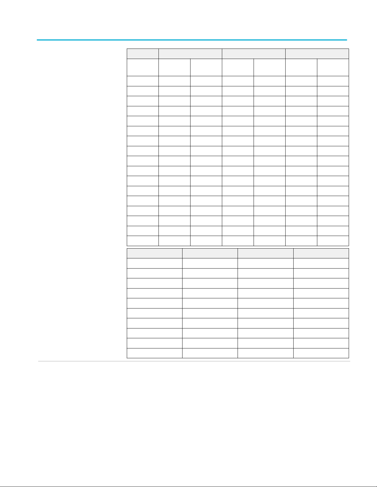
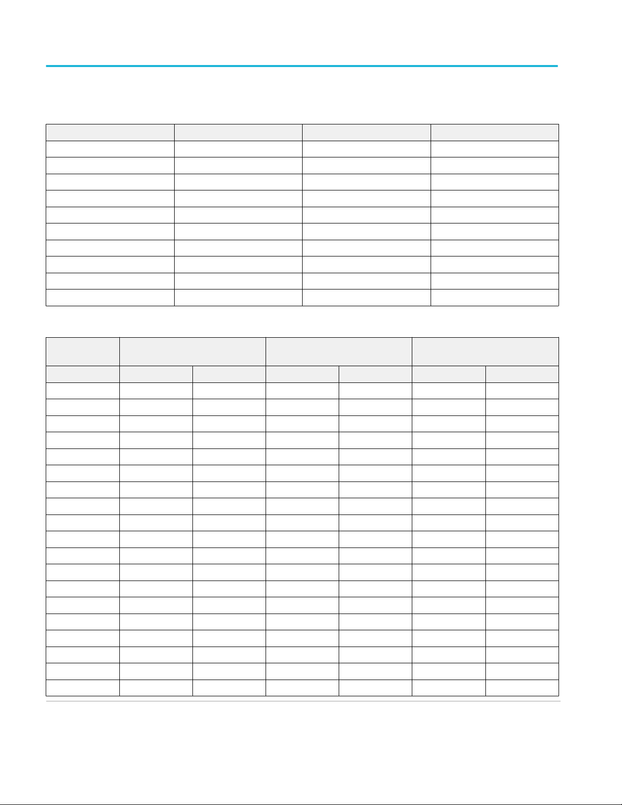
Effective bits, typical, ≥4 GHz
models
DSP on, Enhanced MIMO filter,
full bandwidth
Nine division sine wave input at the indicated frequency, sampled at 500 mVFS vertical sensitivity
and maximum sample rate.
MSO/DPO73304DX MSO/DPO72504DX MSO/DPO72304DX
Input
frequency
10 MHz 5.4 bits 5.4 bits 5.3 bits 5.7 bits 5.3 bits 5.9 bits
1 GHz 5.3 bits 5.2 bits 5.3 bits 5.7 bits 5.2 bits 5.8 bits
2 GHz 5.2 bits 5.2 bits 5.2 bits 5.5 bits 5.2 bits 5.7 bits
3 GHz 5.1 bits 5.1 bits 5.1 bits 5.4 bits 5.1 bits 5.6 bits
4 GHz 5.2 bits 5.1 bits 5.2 bits 5.4 bits 5.2 bits 5.6 bits
5 GHz 5.1 bits 5.2 bits 5.1 bits 5.4 bits 5.1 bits 5.6 bits
6 GHz 5.1 bits 5.0 bits 5.1 bits 5.3 bits 5.0 bits 5.6 bits
7 GHz 5.1 bits 5.0 bits 5.1 bits 5.3 bits 5.1 bits 5.5 bits
8 GHz 5.1 bits 5.1 bits 5.1 bits 5.3 bits 5.1 bits 5.6 bits
9 GHz 5.0 bits 5.1 bits 5.1 bits 5.3 bits 5.0 bits 5.6 bits
10 GHz 5.1 bits 5.2 bits 5.1 bits 5.5 bits 5.0 bits 5.5 bits
11 GHz 4.9 bits 5.1 bits 4.9 bits 5.4 bits 4.9 bits 5.4 bits
12 GHz 5.0 bits 5.2 bits 5.0 bits 5.5 bits 5.0 bits 5.5 bits
13 GHz 4.9 bits 5.1 bits 4.9 bits 5.4 bits 4.9 bits 5.4 bits
14 GHz 4.9 bits 5.1 bits 4.9 bits 5.3 bits 4.8 bits 5.3 bits
15 GHz 4.8 bits 4.9 bits 4.8 bits 5.2 bits 4.8 bits 5.1 bits
16 GHz 4.8 bits 4.8 bits 4.8 bits 5.2 bits 4.7 bits 5.2 bits
17 GHz 4.8 bits 4.9 bits 4.8 bits 5.1 bits 4.7 bits 5.2 bits
18 GHz 4.8 bits 4.9 bits 4.8 bits 5.1 bits 4.8 bits 5.3 bits
19 GHz 4.8 bits 4.8 bits 4.7 bits 5.1 bits 4.7 bits 5.2 bits
20 GHz 4.6 bits 4.7 bits 5.1 bits 5.1 bits 4.7 bits 5.1 bits
21 GHz 4.8 bits 4.8 bits 4.9 bits 5.2 bits 4.8 bits 5.3 bits
22 GHz 4.6 bits 4.8 bits 5.1 bits 4.8 bits 5.3 bits
23 GHz 4.9 bits 5.2 bits 5.2 bits
24 GHz 5.0 bits 5.2 bits
25 GHz 4.8 bits 5.2 bits
26 GHz 4.9 bits
27 GHz 4.8 bits
28 GHz 4.7 bits
29 GHz 4.9 bits
30 GHz 4.9 bits
31 GHz 4.8 bits
32 GHz 4.8 bits
33 GHz 4.8 bits
50 GS/s 100 GS/s 50 GS/s 100 GS/s 50 GS/s 100 GS/s
MSO70000C/DX, DPO70000C/DX, DPO7000C, MSO5000/B, DPO5000/B Series 17
Page 30

Specifications (MSO70000C/DX, DPO70000C/DX, and DPO7000C series) Vertical system analog channels
(cont.)
DSP on, full bandwidth Nine division sine wave input at the indicated frequency, sampled at 500 mVFS vertical sensitivity
and maximum sample rate
MSO/DPO73304DX MSO/DPO72504DX MSO/DPO72304DX
Input
frequency
10 MHz 5.2 bits 5.4 bits 5.2 bits 5.7 bits 5.2 bits 6.0 bits
1 GHz 5.0 bits 5.4 bits 5.0 bits 5.4 bits 5.0 bits 5.5 bits
2 GHz 5.0 bits 5.4 bits 5.0 bits 5.1 bits 5.0 bits 5.3 bits
3 GHz 4.9 bits 5.0 bits 4.9 bits 5.3 bits 4.9 bits 5.4 bits
4 GHz 4.8 bits 4.5 bits 4.6 bits 4.6 bits 4.5 bits 4.8 bits
5 GHz 4.7 bits 4.7 bits 4.7 bits 5.0 bits 4.7 bits 5.3 bits
6 GHz 4.7 bits 4.8 bits 4.7 bits 5.0 bits 4.7 bits 5.2 bits
7 GHz 4.8 bits 4.9 bits 4.8 bits 5.2 bits 4.8 bits 5.3 bits
8 GHz 4.8 bits 5.0 bits 4.8 bits 5.0 bits 4.8 bits 5.4 bits
9 GHz 4.7 bits 5.0 bits 4.7 bits 5.2 bits 4.7 bits 5.3 bits
10 GHz 4.7 bits 5.0 bits 4.7 bits 5.3 bits 4.7 bits 5.4 bits
11 GHz 4.7 bits 5.0 bits 4.7 bits 5.1 bits 4.7 bits 5.2 bits
12 GHz 4.7 bits 5.1 bits 4.7 bits 5.2 bits 4.7 bits 5.3 bits
13 GHz 4.7 bits 4.7 bits 4.7 bits 5.1 bits 4.7 bits 5.2 bits
14 GHz 4.8 bits 5.0 bits 4.8 bits 5.2 bits 4.8 bits 5.2 bits
15 GHz 4.6 bits 4.8 bits 4.6 bits 5.0 bits 4.6 bits 5.1 bits
16 GHz 4.6 bits 4.6 bits 4.6 bits 5.0 bits 4.6 bits 5.2 bits
17 GHz 4.6 bits 4.8 bits 4.6 bits 5.0 bits 4.6 bits 5.1 bits
18 GHz 4.6 bits 4.7 bits 4.6 bits 4.9 bits 4.6 bits 5.1 bits
19 GHz 4.6 bits 4.5 bits 4.6 bits 4.8 bits 4.6 bits 5.0 bits
20 GHz 4.5 bits 4.4 bits 4.6 bits 4.8 bits 4.6 bits 5.0 bits
21 GHz 4.6 bits 4.4 bits 4.6 bits 4.8 bits 4.6 bits 5.1 bits
22 GHz 4.6 bits 4.6 bits 4.6 bits 4.8 bits 4.6 bits 5.1 bits
23 GHz 4.6 bits 5.0 bits 5.1 bits
24 GHz 4.7 bits 4.9 bits
25 GHz 4.7 bits 5.1 bits
26GHz 4.6 bits
27 GHz 4.6 bits
28 GHz 4.6 bits
29 GHz 4.6 bits
30 GHz 4.6 bits
31 GHz 4.5 bits
32 GHz 4.5 bits
33 GHz 4.5 bits
50 GS/s 100 GS/s 50 GS/s 100 GS/s 50 GS/s 100 GS/s
18 MSO70000C/DX, DPO70000C/DX, DPO7000C, MSO5000/B, DPO5000/B Series
Page 31

Vertical system analog channels (cont.) Specifications (MSO70000C/DX, DPO70000C/DX, and DPO7000C
series)
Enhanced bandwidth
MSO/DPO72004C MSO/DPO71604C MSO/DPO71254C
Input
frequency
10 MHz 5.0 bits 5.3 bits 5.6 bits 6.0 bits 5.9 bits 6.2 bits
1 GHz 5.0 bits 5.3 bits 5.6 bits 5.9 bits 5.8 bits 6.1 bits
2 GHz 4.9 bits 5.2 bits 5.6 bits 5.9 bits 5.7 bits 5.9 bits
3 GHz 4.9 bits 5.0 bits 4.6 bits 4.4 bits 4.8 bits 4.5 bits
4 GHz 4.8 bits 4.9 bits 4.2 bits 4.0 bits 4.3 bits 4.0 bits
5 GHz 4.8 bits 4.9 bits 4.6 bits 4.4 bits 5.5 bits 5.2 bits
6 GHz 4.7 bits 4.8 bits 4.5 bits 4.3 bits 4.9 bits 4.8 bits
7 GHz 4.0 bits 3.97 bits 3.9 bits 3.7 bits 5.5 bits 5.6 bits
8 GHz 3.6 bits 3.9 bits 3.4 bits 3.5 bits 5.6 bits 5.8 bits
9 GHz 3.2 bits 3.2 bits 5.1 bits 5.1 bits 5.6 bits 5.8 bits
10 GHz 2.8 bits 2.8 bits 5.5 bits 5.7 bits 5.6 bits 5.8 bits
11 GHz 3.9 bits 3.9 bits 5.4 bits 5.6 bits 5.6 bits 5.8 bits
12 GHz 4.8 bits 5.0 bits 5.4 bits 5.6 bits 5.6 bits 5.7 bits
13 GHz 4.5 bits 4.7 bits 5.2 bits 5.4 bits
14 GHz 4.4 bits 4.6 bits 5.1 bits 5.3 bits
15 GHz 4.5 bits 4.7 bits 5.1 bits 5.0 bits
16 GHz 4.5 bits 4.7 bits 4.8 bits 5.0 bits
17 GHz 4.1 bits 4.6 bits
18 GHz 4.2 bits 4.7 bits
19 GHz 4.6 bits 4.8 bits
20 GHz 4.8 bits 5.0 bits
50 GS/s 100 GS/s 50 GS/s 100 GS/s 50 GS/s 100 GS/s
Enhanced bandwidth
MSO/DPO70804C MSO/DPO70604C MSO/DPO70404C
Input frequency 25 GS/s 25 GS/s 25 GS/s
10 MHz 5.7 bits 5.8 bits 6.0 bits
1 GHz 5.7 bits 5.8 bits 5.9 bits
2 GHz 5.7 bits 5.7 bits 5.8 bits
3 GHz 5.5 bits 5.6 bits 5.7 bits
4 GHz 5.5 bits 5.6 bits 5.7 bits
5 GHz 5.5 bits 5.5 bits
6 GHz 5.4 bits 5.4 bits
7 GHz 5.4 bits
8 GHz 5.3 bits
MSO70000C/DX, DPO70000C/DX, DPO7000C, MSO5000/B, DPO5000/B Series 19
Page 32

Specifications (MSO70000C/DX, DPO70000C/DX, and DPO7000C series) Vertical system analog channels
(cont.)
Without enhanced bandwidth
MSO/DPO73304DX MSO/DPO72504DX MSO/DPO72304DX
Input
frequency
10 MHz 5.2 bits 5.2 bits 5.2 bits 5.2 bits 5.2 bits 5.4 bits
1 GHz 4.8 bits 4.8 bits 5.0 bits 5.0 bits 5.0 bits 5.0 bits
2 GHz 4.9 bits 4.9 bits 5.0 bits 5.0 bits 5.0 bits 5.1 bits
3 GHz 4.8 bits 4.8 bits 4.9 bits 4.9 bits 4.9 bits 5.1 bits
4 GHz 4.7 bits 4.7 bits 4.5 bits 4.7 bits 4.7 bits 4.7 bits
5 GHz 4.7 bits 4.7 bits 4.7 bits 4.7 bits 4.7 bits 4.8 bits
6 GHz 4.7 bits 4.7 bits 4.7 bits 4.7 bits 4.7 bits 4.8 bits
7 GHz 4.7 bits 4.7 bits 4.7 bits 4.7 bits 4.7 bits 4.9 bits
8 GHz 4.6 bits 4.6 bits 4.8 bits 4.8 bits 4.7 bits 4.9 bits
9 GHz 4.7 bits 4.6 bits 4.7 bits 4.7 bits 4.7 bits 4.9 bits
10 GHz 4.7 bits 4.7 bits 4.7 bits 4.7 bits 4.7 bits 4.9 bits
11 GHz 4.7 bits 4.7 bits 4.7 bits 4.7 bits 4.7 bits 4.9 bits
12 GHz 4.7 bits 4.7 bits 4.7 bits 4.7 bits 4.7 bits 4.9 bits
13 GHz 4.5 bits 4.5 bits 4.5 bits 4.5 bits 4.5 bits 4.8 bits
14 GHz 4.7 bits 4.7 bits 4.7 bits 4.7 bits 4.7 bits 4.9 bits
15 GHz 4.6 bits 4.6 bits 4.6 bits 4.6 bits 4.6 bits 4.7 bits
16 GHz 4.5 bits 4.4 bits 4.5 bits 4.4 bits 4.5 bits 4.7 bits
17 GHz 4.5 bits 4.4 bits 4.5 bits 4.4 bits 4.5 bits 4.7 bits
18 GHz 4.5 bits 4.4 bits 4.5 bits 4.4 bits 4.5 bits 4.6 bits
19 GHz 4.2 bits 4.1 bits 4.5 bits 4.4 bits 4.5 bits 4.5 bits
20 GHz 4.3 bits 4.2 bits 4.5 bits 4.5 bits 4.5 bits 4.5 bits
21 GHz 4.5 bits 4.5 bits 4.6 bits 4.6 bits 4.5 bits 4.6 bits
22 GHz 4.5 bits 4.4 bits 4.6 bits 4.6 bits 4.5 bits 4.8 bits
23 GHz 4.5 bits 4.4 bits 4.6 bits 4.6 bits 4.3 bits 4.8 bits
24 GHz 4.4 bits 4.5 bits 4.6 bits 4.6 bits
25 GHz 4.5 bits 4.4 bits 4.5 bits 4.5 bits
26GHz 4.4 bits 4.3 bits
27 GHz 4.1 bits 4.34 bits
28 GHz 4.1 bits 4.1 bits
29 GHz 4.2 bits 3.8 bits
30 GHz 4.2 bits 4.2 bits
31 GHz 4.4 bits 4.2 bits
32 GHz 4.1 bits 4.1 bits
33 GHz 4.3 bits 4.2 bits
50 GS/s 100 GS/s 50 GS/s 100 GS/s 50 GS/s 100 GS/s
20 MSO70000C/DX, DPO70000C/DX, DPO7000C, MSO5000/B, DPO5000/B Series
Page 33
Vertical system analog channels (cont.) Specifications (MSO70000C/DX, DPO70000C/DX, and DPO7000C
series)
Without enhanced bandwidth
MSO/DPO72004C MSO/DPO71604C MSO/DPO71254C
Input
frequency
10 MHz 5.4 bits 2.0 bits 5.4 bits 2.0 bits 5.6 bits 2.0 bits
1 GHz 5.4 bits 2.0 bits 5.4 bits 2.0 bits 5.5 bits 2.0 bits
2 GHz 5.3 bits 2.0 bits 5.3 bits 2.0 bits 5.4 bits 2.0 bits
3 GHz 5.3 bits 2.0 bits 4.6 bits 2.0 bits 4.6 bits 2.0 bits
4 GHz 5.2 bits 2.0 bits 4.3 bits 2.0 bits 4.4 bits 2.0 bits
5 GHz 5.2 bits 2.0 bits 4.6 bits 2.0 bits 5.3 bits 2.0 bits
6 GHz 5.0 bits 2.0 bits 4.4 bits 2.0 bits 5.2 bits 2.0 bits
7 GHz 4.8 bits 2.0 bits 4.1 bits 2.0 bits 4.5 bits 2.0 bits
8 GHz 4.4 bits 2.0 bits 3.4 bits 2.0 bits 5.0 bits 2.0 bits
9 GHz 4.1 bits 2.0 bits 3.2 bits 2.0 bits 5.0 bits 2.0 bits
10 GHz 4.0 bits 2.0 bits 3.5 bits 2.0 bits 5.1 bits 2.0 bits
11 GHz 4.1 bits 2.0 bits 4.1 bits 2.0 bits 5.2 bits 2.0 bits
12 GHz 3.8 bits 2.0 bits 3.5 bits 2.0 bits 5.1 bits 2.0 bits
13 GHz 4.1 bits 2.0 bits 4.1 bits 2.0 bits
14 GHz 4.7 bits 2.0 bits 4.7 bits 2.0 bits
15 GHz 4.7 bits 2.0 bits 4.7 bits 2.0 bits
16 GHz 4.7 bits 2.0 bits 4.7 bits 2.0 bits
50 GS/s 100 GS/s 50 GS/s 100 GS/s 50 GS/s 100 GS/s
Without enhanced bandwidth
MSO/DPO70804C MSO/DPO70604C MSO/DPO70404C
Input frequency 25 GS/s 25 GS/s 25 GS/s
10 MHz 5.6 bits 5.7 bits 5.8 bits
1 GHz 5.6 bits 5.7 bits 5.8 bits
2 GHz 5.4 bits 5.6 bits 5.7 bits
3 GHz 5.4 bits 5.5 bits 5.6 bits
4 GHz 5.3 bits 5.4 bits 5.6 bits
5 GHz 5.2 bits 5.3 bits
6 GHz 5.2 bits 5.3 bits
7 GHz 5.2 bits
8 GHz 5.7 bits
MSO70000C/DX, DPO70000C/DX, DPO7000C, MSO5000/B, DPO5000/B Series 21
Page 34

Specifications (MSO70000C/DX, DPO70000C/DX, and DPO7000C series) Vertical system analog channels
(cont.)
Effective bits, typical, <4 GHz
models
DPO7354C, Enhanced
bandwidth
40 GS/s Analog bandwidth setting
Input Frequency 3.5 GHz 3.0 GHz 2.5 GHz 2.0 GHz 1.0 GHz 0.5 GHz
10 MHz 5.9 bits 6.1 bits 6.2 bits 6.4 bits 6.8 bits 7.1 bits
510 MHz 5.9 bits 6.0 bits 6.1 bits 6.4 bits 6.8 bits 7.1 bits
1010 MHz 5.6 bits 5.7 bits 5.8 bits 6.1 bits 6.8 bits
1510 MHz 5.6 bits 5.8 bits 6.2 bits 6.3 bits
2010 MHz 5.8 bits 6.0 bits 6.1 bits 6.3 bits
2510 MHz 5.7 bits 5.7 bits 5.9 bits
3010 MHz 5.7 bits 5.8 bits
3510 MHz 5.6 bits
20 GS/s Analog bandwidth setting
Input Frequency 3.5 GHz 3.0 GHz 2.5 GHz 2.0 GHz 1.0 GHz 0.5 GHz
10 MHz 5.8 bits 6.0 bits 6.2 bits 6.3 bits 6.7 bits 7.0 bits
510 MHz 5.8 bits 6.0 bits 6.1 bits 6.3 bits 6.7 bits 7.0 bits
1010 MHz 5.6 bits 5.6 bits 5.7 bits 6.0 bits 6.7 bits
1510 MHz 5.6 bits 5.8 bits 6.1 bits 6.2 bits
2010 MHz 5.8 bits 6.0 bits 6.1 bits 6.2 bits
2510 MHz 5.6 bits 5.7 bits 5.8 bits
3010 MHz 5.7 bits 5.7 bits
3510 MHz 5.5 bits
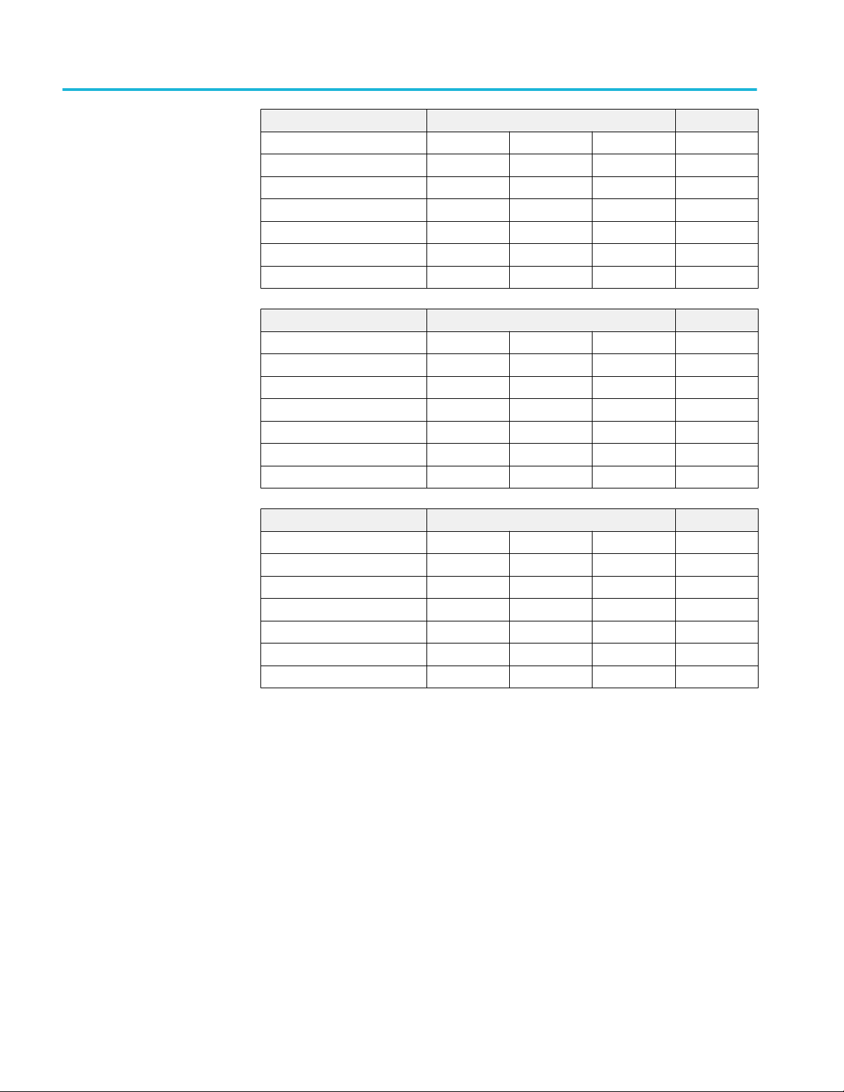
DPO7354C, Without enhanced
bandwidth
10 GS/s Analog bandwidth setting
Input Frequency 3.5 GHz 3.0 GHz 2.5 GHz 2.0 GHz 1.0 GHz 0.5 GHz
10 MHz 5.8 bits 5.9 bits 6.1 bits 6.2 bits 6.7 bits 7.0 bits
510 MHz 5.7 bits 5.9 bits 6.0 bits 6.2 bits 6.7 bits 7.0 bits
1010 MHz 5.5 bits 5.6 bits 5.7 bits 6.0 bits 6.7 bits
1510 MHz 5.5 bits 5.7 bits 6.0 bits 6.1 bits
2010 MHz 5.6 bits 5.8 bits 6.0 bits 6.1 bits
2510 MHz 5.5 bits 5.6 bits 5.7 bits
3010 MHz 5.6 bits 5.7 bits
3510 MHz 5.4 bits
40 GS/s Analog bandwidth setting
Input Frequency 2.5 GHz 0.5 GHz 0.25 GHz 0.02 GHz
10 MHz 5.9 bits 6.3 bits 6.5 bits 6.6 bits
510 MHz 5.8 bits 6.3 bits
1010 MHz 5.6 bits
1510 MHz 5.6 bits
22 MSO70000C/DX, DPO70000C/DX, DPO7000C, MSO5000/B, DPO5000/B Series
Page 35

Vertical system analog channels (cont.) Specifications (MSO70000C/DX, DPO70000C/DX, and DPO7000C
series)
40 GS/s Analog bandwidth setting
2010 MHz 5.1 bits
2510 MHz 4.6 bits
20 GS/s Analog bandwidth setting
Input Frequency 2.5 GHz 0.5 GHz 0.25 GHz 0.02 GHz
10 MHz 5.9 bits 6.3 bits 6.5 bits 6.6 bits
510 MHz 5.8 bits 6.3 bits
1010 MHz 5.6 bits
1510 MHz 5.6 bits
2010 MHz 5.2 bits
2510 MHz 4.6 bits
10 GS/s Analog bandwidth setting
Input Frequency 2.5 GHz 0.5 GHz 0.25 GHz 0.02 GHz
10 MHz 5.9 bits 6.3 bits 6.5 bits 6.6 bits
510 MHz 5.8 bits 6.3 bits
1010 MHz 5.6 bits
1510 MHz 5.7 bits
2010 MHz 5.7 bits
2510 MHz 5.5 bits
MSO70000C/DX, DPO70000C/DX, DPO7000C, MSO5000/B, DPO5000/B Series 23
Page 36
Specifications (MSO70000C/DX, DPO70000C/DX, and DPO7000C series) Vertical system analog channels
(cont.)
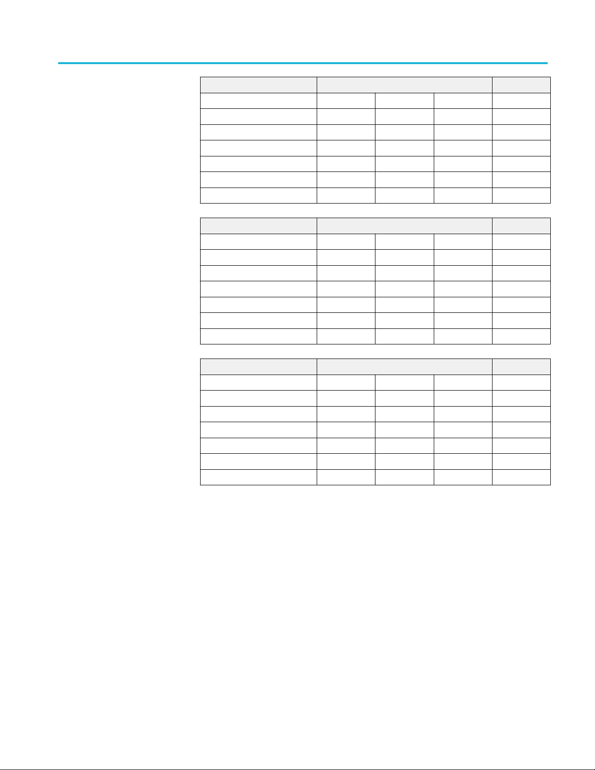
DPO7254C, Enhanced
bandwidth
40 GS/s Analog bandwidth setting
Input Frequency 2.5 GHz 2.0 GHz 1.0 GHz 0.5 GHz
10 MHz 6.2 bits 6.4 bits 6.9 bits 7.2 bits
510 MHz 6.1 bits 6.3 bits 6.9 bits 7.2 bits
1010 MHz 5.9 bits 6.1 bits 6.9 bits
1510 MHz 6.1 bits 6.4 bits
2010 MHz 6.1 bits 6.3 bits
2510 MHz 5.6 bits
20 GS/s Analog bandwidth setting
Input Frequency 2.5 GHz 2.0 GHz 1.0 GHz 0.5 GHz
10 MHz 6.1 bits 6.3 bits 6.8 bits 7.1 bits
510 MHz 6.1 bits 6.3 bits 6.8 bits 7.1 bits
1010 MHz 5.8 bits 6.1 bits 6.8 bits
1510 MHz 6.0 bits 6.3 bits
2010 MHz 6.1 bits 6.3 bits
2510 MHz 5.6 bits
10 GS/s Analog bandwidth setting
Input Frequency 2.5 GHz 2.0 GHz 1.0 GHz 0.5 GHz
10 MHz 6.1 bits 6.4 bits 6.9 bits 7.2 bits
510 MHz 6.1 bits 6.3 bits 6.9 bits 7.2 bits
1010 MHz 5.7 bits 6.1 bits 6.9 bits
1510 MHz 5.9 bits 6.4 bits
2010 MHz 6.0 bits 6.3 bits
2510 MHz 5.5 bits
24 MSO70000C/DX, DPO70000C/DX, DPO7000C, MSO5000/B, DPO5000/B Series
Page 37
Vertical system analog channels (cont.) Specifications (MSO70000C/DX, DPO70000C/DX, and DPO7000C
series)
DPO7254C, Without enhanced
bandwidth
40 GS/s Analog bandwidth setting
Input Frequency 2.5 GHz 0.5 GHz 0.25 GHz 0.02 GHz
10 MHz 5.9 bits 6.3 bits 6.5 bits 6.6 bits
510 MHz 5.9 bits 6.3 bits
1010 MHz 5.6 bits
1510 MHz 5.6 bits
2010 MHz 5.2 bits
2510 MHz 4.5 bits
20 GS/s Analog bandwidth setting
Input Frequency 2.5 GHz 0.5 GHz 0.25 GHz 0.02 GHz
10 MHz 5.9 bits 6.3 bits 6.5 bits 6.6 bits
510 MHz 5.9 bits 6.3 bits
1010 MHz 5.6 bits
1510 MHz 5.6 bits
2010 MHz 5.2 bits
2510 MHz 4.5 bits
10 GS/s Analog bandwidth setting
Input Frequency 2.5 GHz 0.5 GHz 0.25 GHz 0.02 GHz
10 MHz 5.9 bits 6.3 bits 6.5 bits 6.6 bits
510 MHz 5.9 bits 6.3 bits
1010 MHz 5.6 bits
1510 MHz 5.7 bits
2010 MHz 5.8 bits
2510 MHz 5.5 bits
MSO70000C/DX, DPO70000C/DX, DPO7000C, MSO5000/B, DPO5000/B Series 25
Page 38
Specifications (MSO70000C/DX, DPO70000C/DX, and DPO7000C series) Vertical system analog channels
(cont.)
DPO7104C, Enhanced
bandwidth
DPO7104C, Without enhanced
bandwidth
20 GS/s Analog bandwidth setting
Input Frequency 1.0 GHz 0.5 GHz
10 MHz 6.7 bits 7.2 bits
510 MHz 6.7 bits 7.2 bits
1010 MHz 6.7 bits
10 GS/s Analog bandwidth setting
Input Frequency 1.0 GHz 0.5 GHz
10 MHz 6.6 bits 7.1 bits
510 MHz 6.5 bits 7.1 bits
1010 MHz 6.5 bits
5 GS/s Analog bandwidth setting
Input Frequency 1.0 GHz 0.5 GHz
10 MHz 6.4 bits 7.0 bits
510 MHz 6.4 bits 7.0 bits
1010 MHz 6.3 bits
20 GS/s Analog bandwidth setting
Input Frequency 1.0 GHz 0.5 GHz 0.25 GHz 0.02 GHz
10 MHz 6.4 bits 6.4 bits 6.6 bits 6.7 bits
510 MHz 6.1 bits 6.4 bits
1010 MHz 5.7 bits
10 GS/s Analog bandwidth setting
Input Frequency 1.0 GHz 0.5 GHz 0.25 GHz 0.02 GHz
10 MHz 6.4 bits 6.4 bits 6.6 bits 6.7 bits
510 MHz 6.3 bits 6.4 bits
1010 MHz 6.3 bits
5 GS/s Analog bandwidth setting
Input Frequency 1.0 GHz 0.5 GHz 0.25 GHz 0.02 GHz
10 MHz 6.4 bits 6.4 bits 6.6 bits 6.7 bits
510 MHz 6.3 bits 6.4 bits
1010 MHz 6.3 bits
26 MSO70000C/DX, DPO70000C/DX, DPO7000C, MSO5000/B, DPO5000/B Series
Page 39

Vertical system analog channels (cont.) Specifications (MSO70000C/DX, DPO70000C/DX, and DPO7000C
series)
DPO7054C, Enhanced
bandwidth
DPO7054C, Without enhanced
bandwidth
10 GS/s Analog bandwidth setting
Input Frequency 0.5 GHz
10 MHz 6.8 bits
510 MHz 6.8 bits
5 GS/s Analog bandwidth setting
Input Frequency 0.5 GHz
10 MHz 6.7 bits
510 MHz 6.7 bits
2.5 GS/s Analog bandwidth setting
Input Frequency 0.5 GHz
10 MHz 6.5 bits
510 MHz 6.4 bits
10 GS/s Analog bandwidth setting
Input Frequency 0.5 GHz 0.25 GHz 0.02 GHz
10 MHz 6.5 bits 6.6 bits 6.7 bits
510 MHz 6.4 bits
5 GS/s Analog bandwidth setting
Input Frequency 0.5 GHz 0.25 GHz 0.02 GHz
10 MHz 6.5 bits 6.6 bits 6.7 bits
510 MHz 6.4 bits
2.5 GS/s Analog bandwidth setting
Input Frequency 0.5 GHz 0.25 GHz 0.02 GHz
10 MHz 6.5 bits 6.6 bits 6.7 bits
510 MHz 6.4 bits
MSO70000C/DX, DPO70000C/DX, DPO7000C, MSO5000/B, DPO5000/B Series 27
Page 40
Specifications (MSO70000C/DX, DPO70000C/DX, and DPO7000C series) Vertical system analog channels
(cont.)
Noise typical >20 GHz models
Without enhanced bandwidth
Gain setting, full scale MSO/DPO73304DX MSO/DPO72504DX MSO/DPO72304DX
62.5 mV 0.88 mV 0.83 mV 0.79 mV
100 mV 0.96 mV 0.90 mV 0.86 mV
200 mV 1.53 mV 1.47 mV 1.41 mV
500 mV 4.19 mV 3.57 mV 3.14 mV
1 V 8.30 mV 6.94 mV 6.10 mV
2.0 V 18.84 mV 16.70 mV 14.19 mV
3.0 V 24.64 mV 21.53 mV 19.09 mV
4.0 V 37.91 mV 31.53 mV 26.01 mV
5.0 V 43.36 mV 36.74 mV 31.84 mV
6.0 V 47.93 mV 41.00 mV 36.97 mV
Enhanced bandwidth
Gain setting, full
scale
62.5 mV 0.84 mV 0.84 mV 0.82 mV 0.90 mV 0.75 mV 0.76 mV
100 mV 0.93 mV 0.93 mV 0.81 mV 0.92 mV 0.78 mV 0.79 mV
150 mV 1.31 mV 1.29 mV 1.17 mV 1.29 mV 1.08 mV 1.19 mV
200 mV 1.52 mV 1.6 mV 1.40 mV 1.56 mV 1.14 mV 1.19 mV
200 mV 2.49 mV 2.52 mV 2.28 mV 2.49 mV 2.10 mV 2.29 mV
400 mV 2.92 mV 2.52 mV 2.80 mV 3.08 mV 2.58 mV 2.29 mV
500 mV 3.55 mV 2.52 mV 3.35 mV 3.75 mV 2.65 mV 2.67 mV
600 mV 4.86 mV 4.86 mV 4.5 mV 4.80 mV 4.14 mV 4.42 mV
700 mV 5.25 mV 5.39 mV 5.04 mV 5.39 mV 4.64 mV 4.96 mV
800 mV 5.76 mV 6.08 mV 5.52 mV 6.00 mV 5.08 mV 5.52 mV
900 mV 5.76 mV 6.66 mV 6.12 mV 6.66 mV 5.63 mV 6.13 mV
1 V 6.80 mV 7.30 mV 6.70 mV 7.20 mV 5.09 mV 5.11 mV
1.1 V 8.69 mV 9.02 mV 8.47 mV 8.91 mV 7.79 mV 8.20 mV
1.2 V 9.12 mV 9.60 mV 9.00 mV 9.48 mV 8.28 mV 8.72 mV
2.0 V 15.4 mV 16.4 mV 12.4 mV 12.9 mV 11.7 mV 11.9 mV
3.0 V 19.9 mV 22.8 mV 17.2 mV 17.7 mV 15.3 mV 15.5 mV
4.0 V 28.8 mV 31.8 mV 24.4 mV 24.9 mV 21.6 mV 21.9 mV
5.0 V 34.3 mV 31.8 mV 28.1 mV 28.7 mV 25.7 mV 25.1 mV
6.0 V 39.8 mV 43.8 mV 34.1 mV 34.8 mV 29.7 mV 30.1 mV
MSO/DPO73304DX MSO/DPO72504DX MSO/DPO72304DX
100 GS/s 50 GS/s 100 GS/s 50 GS/s 100 GS/s 50 GS/s
28 MSO70000C/DX, DPO70000C/DX, DPO7000C, MSO5000/B, DPO5000/B Series
Page 41

Vertical system analog channels (cont.) Specifications (MSO70000C/DX, DPO70000C/DX, and DPO7000C
series)
Noise, typical, ≥4 GHz ≤20 GHz
models
Without enhanced bandwidth
Gain setting, full scale MSO/ DPO
72004C
100 mV 0.87 mV 0.87 mV 0.67 mV 0.58 mV 0.53 mV 0.50 mV
150 mV 1.06 mV 1.06 mV 0.84 mV 0.74 mV 0.73 mV 0.69 mV
200 mV 1.21 mV 1.21 mV 0.98 mV 0.90 mV 0.86 mV 0.86 mV
300 mV 1.82 mV 1.82 mV 1.49 mV 1.34 mV 1.25 mV 1.25 mV
400 mV 2.29 mV 2.29 mV 1.80 mV 1.76 mV 1.67 mV 1.67 mV
500 mV 2.78 mV 2.78 mV 2.29 mV 2.02 mV 2.02 mV 2.02 mV
600 mV 3.35 mV 3.35 mV 2.78 mV 2.52 mV 2.46 mV 2.46 mV
700 mV 3.92 mV 3.92 mV 3.27 mV 3.02 mV 2.90 mV 2.90 mV
800 mV 4.49 mV 4.49 mV 3.76 mV 3.52 mV 3.34 mV 3.34 mV
900 mV 5.14 mV 5.14 mV 4.25 mV 3.87 mV 3.78 mV 3.78 mV
1.0 V 6.48 mV 6.48 mV 4.89 mV 4.50 mV 4.28 mV 4.28 mV
2.0 V 11.47 mV 11.47 mV 8.98 mV 8.80 mV 8.36 mV 8.36 mV
2.5 V 14.04 mV 14.04 mV 11.43 mV 10.81 mV 10.34 mV 10.34 mV
3.0 V 16.61 mV 16.61 mV 13.88 mV 12.82 mV 12.32 mV 12.32 mV
4.0 V 21.83 mV 21.83 mV 18.78 mV 17.36 mV 16.91 mV 16.91 mV
4.5 V 24.41 mV 24.41 mV 21.30 mV 19.44 mV 18.97 mV 18.97 mV
5.0 V 26.99 mV 26.99 mV 23.59 mV 21.51 mV 21.02 mV 21.02 mV
MSO/ DPO
71604C
MSO/ DPO
71254C
MSO/ DPO
70804C
MSO/ DPO
70604C
MSO/ DPO
70404C
Enhanced bandwidth, sample rates less than 100 GS/s.
MSO/DPO72004C
MSO/DPO71604C
MSO/DPO71254C
where applicable
Gain Setting, full scale
100 mV NA NA 1.09 mV 0.70 mV 0.63 mV 0.59 mV
150 mV NA NA 1.06 mV 0.93 mV 0.75 mV 0.79 mV
200 mV 2.08 mV 1.67 mV 1.34 mV 1.09 mV 0.88 mV 0.92 mV
300 mV 3.70 mV 2.35 mV 1.90 mV 1.57 mV 1.35 mV 1.31 mV
400 mV 4.18 mV 3.10 mV 2.53 mV 2.08 mV 1.68 mV 1.67 mV
500 mV 3.55 mV 3.10 mV 2.61 mV 2.29 mV 2.04 mV 2.02 mV
600 mV 5.06 mV 3.70 mV 3.13 mV 2.78 mV 2.45 mV 2.46 mV
700 mV 6.09 mV 4.30 mV 3.65 mV 3.27 mV 2.99 mV 2.90 mV
800 mV 6.62 mV 4.90 mV 4.16 mV 3.76 mV 3.40 mV 3.34 mV
900 mV 7.21 mV 5.31 mV 4.57 mV 4.16 mV 3.71 mV 3.59 mV
1.0 V 10.52 mV 8.35 mV 7.98 mV 5.32 mV 4.55 mV 4.50 mV
2.0 V 21.38 mV 15.54 mV 12.66 mV 10.28 mV 8.33 mV 8.70 mV
20 GHz 19 GHz 18 GHz 17 GHz 16 GHz 15 GHz
MSO70000C/DX, DPO70000C/DX, DPO7000C, MSO5000/B, DPO5000/B Series 29
Page 42

Specifications (MSO70000C/DX, DPO70000C/DX, and DPO7000C series) Vertical system analog channels
(cont.)
MSO/DPO72004C
MSO/DPO71604C
MSO/DPO71254C
where applicable
2.5 V 17.77 mV 17.87 mV 14.82 mV 12.26 mV 9.96 mV 10.51 mV
3.0 V 25.05 mV 20.20 mV 16.88 mV 14.24 mV 12.17 mV 12.32 mV
4.0 V 33.34 mV 24.86 mV 21.17 mV 18.26 mV 17.07 mV 15.98 mV
4.5 V 35.86 mV 27.20 mV 23.29 mV 20.25 mV 18.6 mV 17.80 mV
5.0 V 38.40 mV 29.53 mV 25.41 mV 22.23 mV 20.29 mV 19.61 mV
MSO/DPO72004C
MSO/DPO71604C
MSO/DPO71254C
where applicable
Gain Setting, full scale
100 mV 0.58 mV 0.58 mV 0.55 mV 0.53 mV 0.51 mV 0.49 mV
150 mV 0.77 mV 0.73 mV 0.72 mV 0.71 mV 0.68 mV 0.65 mV
200 mV 0.87 mV 0.84 mV 0.82 mV 0.81 mV 0.78 mV 0.75 mV
300 mV 1.28 mV 1.26 mV 1.28 mV 1.20 mV 1.16 mV 1.10 mV
400 mV 1.63 mV 1.59 mV 1.67 mV 1.49 mV 1.43 mV 1.39 mV
500 mV 1.92 mV 1.85 mV 1.80 mV 1.78 mV 1.72 mV 1.65 mV
600 mV 2.35 mV 2.27 mV 2.42 mV 2.18 mV 2.12 mV 1.99 mV
700 mV 2.79 mV 2.69 mV 2.94 mV 2.58 mV 2.51 mV 2.34 mV
800 mV 3.23 mV 3.10 mV 3.40 mV 2.98 mV 2.90 mV 2.78 mV
900 mV 3.51 mV 3.39 mV 3.63 mV 3.27 mV 3.14 mV 3.02 mV
1.0 V 4.26 mV 4.22 mV 4.09 mV 4.05 mV 3.94 mV 3.73 mV
2.0 V 8.23 mV 7.96 mV 8.39 mV 7.47 mV 7.16 mV 6.93 mV
2.5 V 9.95 mV 9.62 mV 9.57 mV 9.03 mV 8.68 mV 8.35 mV
3.0 V 11.68 mV 11.27 mV 12.35 mV 10.58 mV 10.19 mV 9.76 mV
4.0 V 15.19 mV 15.34 mV 17.26 mV 14.79 mV 14.29 mV 13.60 mV
4.5 V 16.92 mV 17.09 mV 18.49 mV 16.47 mV 15.93 mV 15.12 mV
5.0 V 18.66 mV 18.83 mV 19.60 mV 18.15 mV 17.56 mV 16.65 mV
20 GHz 19 GHz 18 GHz 17 GHz 16 GHz 15 GHz
14 GHz 13 GHz 12.5 GHz 12 GHz 11 GHz 10 GHz
30 MSO70000C/DX, DPO70000C/DX, DPO7000C, MSO5000/B, DPO5000/B Series
Page 43

Vertical system analog channels (cont.) Specifications (MSO70000C/DX, DPO70000C/DX, and DPO7000C
series)
MSO/DPO72004C
MSO/DPO71604C
MSO/DPO71254C
where applicable
Gain Setting, full scale
100 mV 0.46 mV 0.45 mV 0.43 mV 0.40 mV 0.37 mV 0.34 mV
150 mV 0.63 mV 0.60 mV 0.57 mV 0.54 mV 0.51 mV 0.48 mV
200 mV 0.71 mV 0.67 mV 0.63 mV 0.60 mV 0.57 mV 0.53 mV
300 mV 1.03 mV 0.99 mV 0.95 mV 0.89 mV 0.84 mV 0.77 mV
400 mV 1.33 mV 1.27 mV 1.18 mV 1.10 mV 1.06 mV 0.98 mV
500 mV 1.57 mV 1.48 mV 1.41 mV 1.31 mV 1.22 mV 1.10 mV
600 mV 1.89 mV 1.79 mV 1.71 mV 1.60 mV 1.49 mV 1.35 mV
700 mV 2.21 mV 2.11 mV 2.01 mV 1.88 mV 1.76 mV 1.59 mV
800 mV 2.21 mV 2.11 mV 2.01 mV 1.88 mV 1.76 mV 1.59 mV
900 mV 2.86 mV 2.74 mV 2.61 mV 2.45 mV 2.29 mV 2.08 mV
1.0 V 3.55 mV 3.36 mV 3.18 mV 2.99 mV 2.77 mV 2.65 mV
2.0 V 6.55 mV 6.33 mV 5.94 mV 5.51 mV 5.28 mV 4.90 mV
2.5 V 7.92 mV 7.63 mV 7.20 mV 6.68 mV 6.34 mV 5.83 mV
3.0 V 9.30 mV 8.93 mV 8.46 mV 7.84 mV 7.40 mV 6.77 mV
4.0 V 13.01 mV 12.40 mV 11.81 mV 11.07 mV 10.37 mV 9.51 mV
4.5 V 14.50 mV 13.80 mV 13.17 mV 12.34 mV 11.53 mV 10.54 mV
5.0 V 15.98 mV 15.20 mV 14.53 mV 13.61 mV 12.68 mV 11.57 mV
9 GHz 8 GHz 7 GHz 6 GHz 5 GHz 4 GHz
MSO70000C/DX, DPO70000C/DX, DPO7000C, MSO5000/B, DPO5000/B Series 31
Page 44

Specifications (MSO70000C/DX, DPO70000C/DX, and DPO7000C series) Vertical system analog channels
(cont.)
MSO/DPO72004C, MSO/
DPO71604C, MSO/
DPO71254C where
applicable
Gain Setting, full scale
100 mV 0.31 mV 0.26 mV 0.20 mV 0.17 mV
150 mV 0.44 mV 0.39 mV 0.34 mV 0.27 mV
200 mV 0.48 mV 0.44 mV 0.37 mV 0.31 mV
300 mV 0.69 mV 0.61 mV 0.52 mV 0.44 mV
400 mV 0.88 mV 0.78 mV 0.66 mV 0.57 mV
500 mV 1.03 mV 0.91 mV 0.76 mV 0.68 mV
600 mV 1.24 mV 1.09 mV 0.91 mV 0.82 mV
700 mV 1.45 mV 1.27 mV 1.06 mV 0.95 mV
800 mV 1.76 mV 1.51 mV 1.10 mV 1.10 mV
900 mV 1.88 mV 1.63 mV 1.35 mV 1.22 mV
1.0 V 2.38 mV 2.02 mV 1.57 mV 1.31 mV
2.0 V 4.43 mV 4.12 mV 3.42 mV 2.88 mV
2.5 V 4.43 mV 4.12 mV 3.42 mV 2.88 mV
3.0 V 6.22 mV 5.63 mV 4.72 mV 4.10 mV
4.0 V 8.83 mV 7.86 mV 6.63 mV 5.86 mV
4.5 V 9.81 mV 8.68 mV 7.34 mV 6.53 mV
5.0 V 10.80 mV 9.51 mV 8.06 mV 7.20 mV
3 GHz 2 GHz 1 GHz 500 MHz
32 MSO70000C/DX, DPO70000C/DX, DPO7000C, MSO5000/B, DPO5000/B Series
Page 45

Vertical system analog channels (cont.) Specifications (MSO70000C/DX, DPO70000C/DX, and DPO7000C
series)
MSO/
DPO70804C,
MSO/
DPO70604C,
MSO/
DPO70404C,
where applicable
Gain Setting, full scale
100 mV 0.54 mV 0.51 mV 0.48 mV 0.45 mV 0.42 mV 0.40 mV
150 mV 0.73 mV 0.69 mV 0.64 mV 0.60 mV 0.55 mV 0.50 mV
200 mV 0.86 mV 0.80 mV 0.77 mV 0.72 mV 0.68 mV 0.60 mV
300 mV 1.34 mV 1.25 mV 1.16 mV 1.07 mV 0.98 mV 0.89 mV
400 mV 1.67 mV 1.58 mV 1.50 mV 1.41 mV 1.32 mV 1.14 mV
500 mV 1.94 mV 1.85 mV 1.76 mV 1.67 mV 1.58 mV 1.41 mV
600 mV 2.41 mV 2.29 mV 2.17 mV 2.04 mV 1.91 mV 1.70 mV
700 mV 2.87 mV 2.73 mV 2.58 mV 2.41 mV 2.23 mV 1.99 mV
800 mV 3.34 mV 3.17 mV 2.99 mV 2.77 mV 2.55 mV 2.29 mV
900 mV 3.70 mV 3.56 mV 3.34 mV 3.12 mV 2.90 mV 2.55 mV
1.0 V 4.28 mV 3.99 mV 3.83 mV 3.46 mV 3.38 mV 3.00 mV
2.0 V 8.36 mV 8.09 mV 7.48 mV 6.95 mV 6.60 mV 5.80 mV
2.5 V 10.23 mV 9.86 mV 9.20 mV 8.61 mV 8.18 mV 7.21 mV
3.0 V 12.10 mV 11.62 mV 10.92 mV 10.27 mV 9.75 mV 8.62 mV
4.0 V 16.61 mV 15.90 mV 14.99 mV 14.18 mV 12.97 mV 11.50 mV
4.5 V 18.57 mV 17.75 mV 16.78 mV 15.91 mV 14.55 mV 12.92 mV
5.0 V 20.53 mV 19.60 mV 18.58 mV 17.65 mV 16.13 mV 14.34 mV
8 GHz 7 GHz 6 GHz 5 GHz 4 GHz 3 GHz
MSO70000C/DX, DPO70000C/DX, DPO7000C, MSO5000/B, DPO5000/B Series 33
Page 46

Specifications (MSO70000C/DX, DPO70000C/DX, and DPO7000C series) Vertical system analog channels
(cont.)
MSO/DPO70804C, MSO/
DPO70604C, MSO/DPO70404C,
where applicable
Gain Setting, full scale
100 mV 0.37 mV 0.32 mV 0.24 mV
150 mV 0.46 mV 0.39 mV 0.32 mV
200 mV 0.55 mV 0.46 mV 0.40 mV
300 mV 0.78 mV 0.67 mV 0.57 mV
400 mV 1.01 mV 0.88 mV 0.76 mV
500 mV 1.23 mV 1.01 mV 0.92 mV
600 mV 1.50 mV 1.23 mV 1.10 mV
700 mV 1.76 mV 1.44 mV 1.28 mV
800 mV 2.02 mV 1.65 mV 1.45 mV
900 mV 2.24 mV 1.89 mV 1.67 mV
1.0 V 2.59 mV 2.03 mV 1.65 mV
2.0 V 5.08 mV 4.19 mV 3.66 mV
2.5 V 6.32 mV 5.20 mV 4.61 mV
3.0 V 6.32 mV 5.20 mV 4.61 mV
4.0 V 10.07 mV 8.28 mV 7.50 mV
4.5 V 10.07 mV 8.28 mV 7.50 mV
5.0 V 12.55 mV 10.31 mV 9.41 mV
2 GHz 1 GHz 500 MHz
34 MSO70000C/DX, DPO70000C/DX, DPO7000C, MSO5000/B, DPO5000/B Series
Page 47

Vertical system analog channels (cont.) Specifications (MSO70000C/DX, DPO70000C/DX, and DPO7000C
series)
Enhanced bandwidth, at 100 GS/s.
MSO/DPO72004C
MSO/DPO71604C
MSO/DPO71254C
Gain Setting, full scale
100 mV N/A N/A 0.981 mV 0.63 mV 0.5706 mV 0.531 mV
150 mV N/A N/A 0.954 mV 0.837 mV 0.729 mV 0.711 mV
200 mV 1.736 mV 1.4195 mV 1.139 mV 0.9265 mV 0.816 mV 0.782 mV
300 mV 2.92 mV 1.9975 mV 1.615 mV 1.3345 mV 1.156 mV 1.1135 mV
400 mV 3.072 mV 2.635 mV 2.1506 mV 1.768 mV 1.53 mV 1.4195 mV
500 mV 2.944 mV 2.635 mV 2.2185 mV 1.9465mV 1.802 mV 1.717 mV1.802 m
600 mV 3.784 mV 3.145 mV 2.6605 mV 2.363 mV 2.176 mV 2.091 mV
700 mV 4.424 mV 3.655 mV 3.1025 mV 2.7795 mV 2.737 mV 2.465 mV
800 mV 4.704 mV 4.165 mV 3.536 mV 3.196 mV 2.9155 mV 2.839 mV
900 mV 5.296 mV 4.5135 mV 3.8845 mV 3.536 mV 3.196 mV 3.0515 mV
1.0 V 8.688 mV 7.0975 mV 6.783 mV 4.522 mV 4.0545 mV 3.825 mV
2.0 V 15.352 mV 13.209 mV 10.761 mV 8.738 mV 7.735 mV 7.395 mV
2.5 V 17.392 mV 15.1895 mV 12.597 mV 10.421mV 9.248 mV 8.9335 mV
3.0 V 19.432 mV 17.17 mV 14.348 mV 12.104 mV 11.407 mV 10.742 mV
4.0 V 25.736 mV 21.131 mV 17.9945 mV 15.521mV 15.2575 mV 13.583 mV
4.5 V 27.52 mV 23.12 mV 19.7965 mV 17.2125 mV 16.184 mV 15.13 mV
5.0 V 30.064 mV 25.1005 mV 21.5985 mV 18.8955 mV 18.0795 mV 16.6685 mV
20 GHz 19 GHz 18 GHz 17 GHz 16 GHz 15 GHz
V
MSO70000C/DX, DPO70000C/DX, DPO7000C, MSO5000/B, DPO5000/B Series 35
Page 48

Specifications (MSO70000C/DX, DPO70000C/DX, and DPO7000C series) Vertical system analog channels
(cont.)
MSO/DPO72004C
MSO/DPO71604C
MSO/DPO71254C
Gain Setting, full scale
100 mV 0.522 mV 0.493 mV 0.4675 mV 0.4505 mV 0.4335 mV 0.4165 mV
150 mV 0.693 mV 0.6205 mV 0.612 mV 0.6035 mV 0.578 mV 0.5525 mV
200 mV 0.7395 mV 0.714 mV 0.697 mV 0.6885 mV 0.663 mV 0.6375 mV
300 mV 1.088 mV 1.071 mV 1.088 mV 1.02 mV 0.986 mV 0.935 mV
400 mV 1.3855 mV 1.3515 mV 1.4195 mV 1.2665 mV 1.2155 mV 1.1815 mV
500 mV 1.632 mV 1.5725 mV 1.53 mV 1.513 mV 1.462 mV 1.4025 mV
600 mV 1.9975 mV 1.9295 mV 2.057 mV 1.853 mV 1.802 mV 1.6915 mV
700 mV 2.3715 mV 2.2865 mV 2.499 mV 2.193 mV 2.1335 mV 1.989 mV
800 mV 2.7455 mV 2.635 mV 2.89 mV 2.533 mV 2.465 mV 2.363 mV
900 mV 2.9835mV 2.8815mV 3.0855 mV 2.7795mV 2.669 mV 2.567 mV
1.0 V 3.621 mV 3.587 mV 3.4765 mV 3.4425 mV 3.349 mV 3.1705 mV
2.0 V 6.9955 mV 6.766 mV 7.1315 mV 6.3495 mV 6.086 mV 5.8905 mV
2.5 V 8.4575 mV 8.177 mV 8.1345 mV 7.6755 mV 7.378 mV 7.0975 mV
3.0 V 9.928 mV 9.5795 mV 10.4975 mV 8.993 mV 8.6615 mV 8.177 mV
4.0 V 12.9115 mV 13.039 mV 14.671 mV 12.5715 mV 12.1465 mV 11.56 mV
4.5 V 14.382 mV 14.5265 mV 15.7165 mV 13.9995 mV 13.5405 mV 12.852 mV
5.0 V 15.861 mV 16.0055 mV 16.66 mV 15.4275 mV 14.926 mV 14.1525 mV
14 GHz 13 GHz 12.5 GHz 12 GHz 11 GHz 10 GHz
36 MSO70000C/DX, DPO70000C/DX, DPO7000C, MSO5000/B, DPO5000/B Series
Page 49
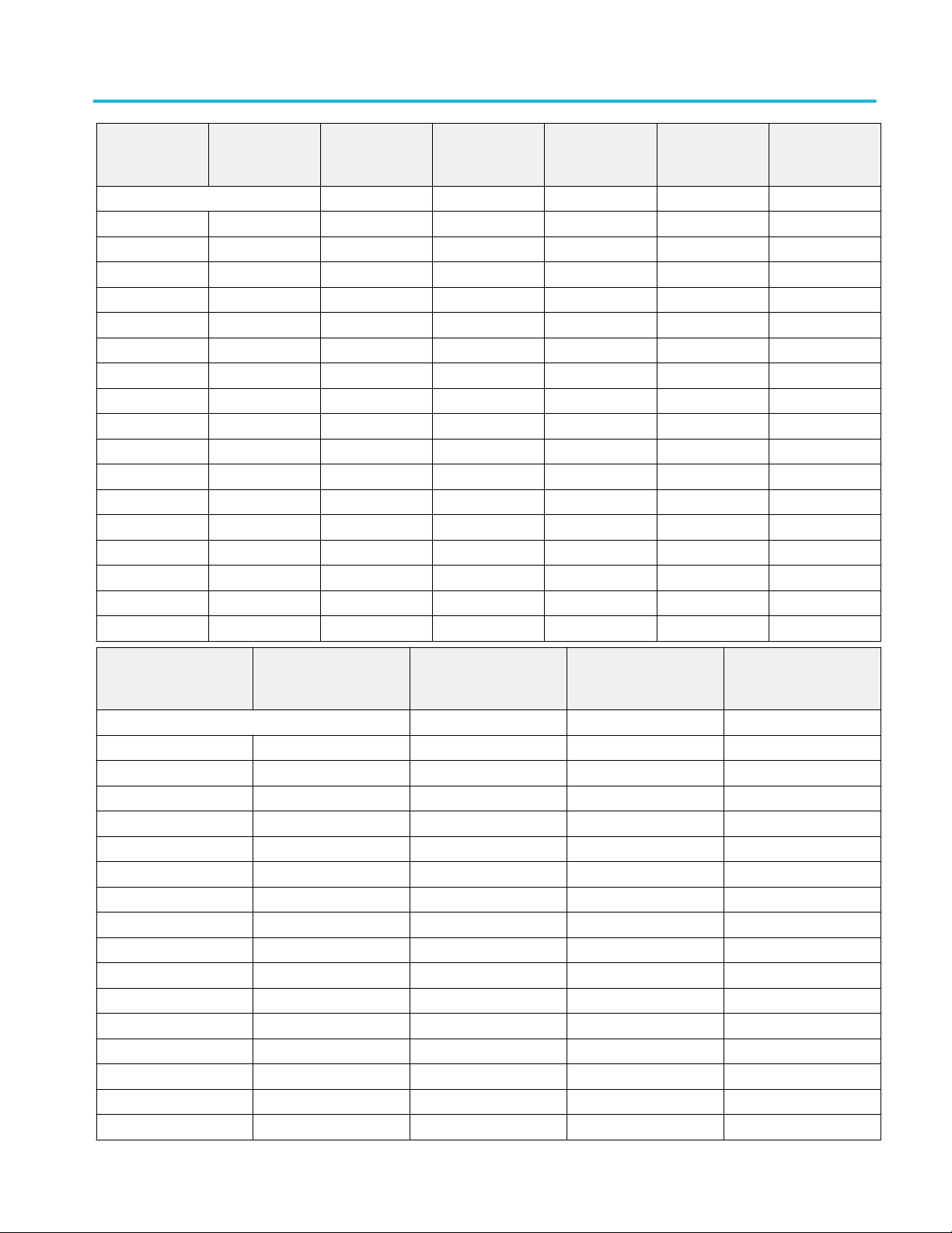
Vertical system analog channels (cont.) Specifications (MSO70000C/DX, DPO70000C/DX, and DPO7000C
series)
MSO/DPO72004C
MSO/DPO71604C
MSO/DPO71254C
Gain Setting, full scale
100 mV 0.391 mV 0.3825 mV 0.387 mV 0.36 mV 0.333 mV 0.306 mV
150 mV 0.5355 mV 0.51 mV 0.513 mV 0.486 mV 0.459 mV 0.432 mV
200 mV 0.6035 mV 0.5695 mV 0.5355 mV 0.51 mV 0.4845 mV 0.4505 mV
300 mV 0.8755 mV 0.8415mV 0.8075 mV 0.7565mV 0.714 mV 0.6545 mV
400 mV 1.1305 mV 1.0795 mV 1.003 mV 0.935 mV 0.901 mV 0.833 mV
500 mV 1.3345 mV 1.258 mV 1.1985 mV 1.1135 mV 1.037 mV 0.935 mV
600 mV 1.6065 mV 1.5215 mV 1.4535 mV 1.36 mV 1.2665 mV 1.1475 mV
700 mV 1.8785 mV 1.7935 mV 1.7085 mV 1.598 mV 1.496 mV 1.3515 mV
800 mV 2.2185 mV 2.1165 mV 2.0145 mV 1.9125 mV 1.768 mV 1.666 mV
900 mV 2.431 mV 2.329 mV 2.2185 mV 2.0825mV 1.9465mV 1.768 mV
1.0 V 2.431 mV 2.329 mV 2.2185 mV 2.0825mV 1.9465mV 1.768 mV
2.0 V 5.5675 mV 5.3805 mV 5.049 mV 4.6835 mV 4.488 mV 4.165 mV
2.5 V 6.732 mV 6.4855 mV 6.12 mV 5.678 mV 5.389 mV 4.9555 mV
3.0 V 7.905 mV 7.5905 mV 7.191 mV 6.664 mV 6.29 mV 5.7545 mV
4.0 V 11.0585mV 10.54 mV 10.0385 mV 9.4095 mV 8.8145 mV 8.0835 mV
4.5 V 12.325 mV 11.73 mV 11.1945 mV 10.489 mV 9.8005 mV 8.959 mV
5.0 V 13.583 mV 12.92 mV 12.3505 mV 11.5685 mV 10.778 mV 9.8345 mV
9 GHz 8 GHz 7GHz 6 GHz 5 GHz 4 GHz
MSO/DPO72004C MSO/
DPO71604C MSO/
DPO71254C
Gain Setting, full scale
100 mV 0.279 mV 0.234 mV 0.18 mV 0.153 mV
150 mV 0.396 mV 0.351 mV 0.306 mV 0.243 mV
200 mV 0.408 mV 0.374 mV 0.3145 mV 0.2635 mV
300 mV 0.5865 mV 0.5185mV 0.442 mV 0.374 mV
400 mV 0.748 mV 0.663 mV 0.561 mV 0.4845 mV
500 mV 0.8755 mV 0.7735 mV 0.646 mV 0.578 mV
600 mV 1.054 mV 0.9265 mV 0.7735 mV 0.697 mV
700 mV 1.2325 mV 1.0795 mV 0.901 mV 0.8075 mV
800 mV 1.496 mV 1.2835 mV 1.037 mV 0.935 mV
900 mV 1.598 mV 1.3855mV 1.1475 mV 1.037 mV
1.0 V 1.598 mV 1.3855mV 1.1475 mV 1.037 mV
2.0 V 3.7655 mV 3.502 mV 2.907 mV 2.448 mV
2.5 V 4.5305 mV 4.1395 mV 3.4595 mV 2.9665 mV
3.0 V 5.287 mV 4.7855 mV 4.012 mV 3.485 mV
4.0 V 7.5055 mV 6.681 mV 5.6355 mV 4.981 mV
4.5 V 8.3385 mV 7.738 mV 6.239 mV 5.5505 mV
3 GHz 2 GHz 1GHz 500 MHz
MSO70000C/DX, DPO70000C/DX, DPO7000C, MSO5000/B, DPO5000/B Series 37
Page 50

Specifications (MSO70000C/DX, DPO70000C/DX, and DPO7000C series) Vertical system analog channels
(cont.)
MSO/DPO72004C MSO/
DPO71604C MSO/
DPO71254C
5.0 V 9.18 mV 8.0835 mV 6.851 mV 6.12 mV
3 GHz 2 GHz 1GHz 500 MHz
38 MSO70000C/DX, DPO70000C/DX, DPO7000C, MSO5000/B, DPO5000/B Series
Page 51

Vertical system analog channels (cont.) Specifications (MSO70000C/DX, DPO70000C/DX, and DPO7000C
series)
Noise, typical, <4 GHz models
DPO7354C Enhanced
bandwidth
40 GS/s
Step gain 3.5 GHz 3.0 GHz 2.5 GHz 2.0 GHz 1.0 GHz 0.5 GHz
500 mV/div 23.5 mV 20.2 mV 18.9 mV 16.5 mV 12.2 mV 9.7 mV
200 mV/div 10.9 mV 9.2 mV 8.1 mV 7.05 mV 5.3 mV 4.1 mV
100 mV/div 6.6 mV 5.4 mV 4.9 mV 4.2 mV 3.05 mV 2.35 mV
50 mV/div 2.35 mV 2.1 mV 1.9 mV 1.7 mV 1.3 mV 1.0 mV
20 mV/div 1.03 mV 0.89 mV 0.811 mV 0.72 mV 0.53 mV 0.43 mV
10 mV/div 0.61 mV 0.55 mV 0.47 mV 0.42 mV 0.3 mV 0.23 mV
5 mV/div 0.41 mV 0.415 mV 0.41 mV 0.4 mV 0.21 mV 0.16 mV
2 mV/div 0.19 mV 0.19 mV 0.19 mV 0.19 mV 0.185 mV 0.185 mV
1 mV/div 0.12 mV 0.12 mV 0.12 mV 0.12 mV 0.12 mV 0.12 mV
20 GS/s
Step gain 3.5 GHz 3.0 GHz 2.5 GHz 2.0 GHz 1.0 GHz 0.5 GHz
500 mV/div 24.3 mV 21.6 mV 19.1 mV 16.7 mV 12.4 mV 9.9 mV
200 mV/div 11.1 mV 9.3 mV 8.4 mV 7.1 mV 5.35 mV 4.2 mV
100 mV/div 6.65 mV 5.5 mV 4.95 mV 4.25 mV 3.1 mV 2.4 mV
50 mV/div 2.45 mV 2.2 mV 1.95 mV 1.8 mV 1.35 mV 1.1 mV
20 mV/div 1.055 mV 0.93 mV 0.83 mV 0.75 mV 0.55 mV 0.435 mV
10 mV/div 0.625 mV 0.55 mV 0.475 mV 0.425 mV 0.31 mV 0.24 mV
5 mV/div 0.415 mV 0.415 mV 0.415 mV 0.415 mV 0.215 mV 0.16 mV
2 mV/div 0.19 mV 0.19 mV 0.19 mV 0.19 mV 0.185 mV 0.185 mV
1 mV/div 0.12 mV 0.12 mV 0.12 mV 0.12 mV 0.12 mV 0.12 mV
10 GS/s
Step gain 3.5 GHz 3.0 GHz 2.5 GHz 2.0 GHz 1.0 GHz 0.5 GHz
500 mV/div 25.8 mV 22.2 mV 20.0 mV 17.7 mV 13.2 mV 10.4 mV
200 mV/div 11.7 mV 9.9 mV 8.7 mV 7.5 mV 5.5 mV 4.3 mV
100 mV/div 6.9 mV 5.6 mV 5.0 mV 4.3 mV 3.2 mV 2.4 mV
50 mV/div 2.6 mV 2.3 mV 2.05 mV 1.85 mV 1.4 mV 1.15 mV
20 mV/div 1.11 mV 0.99 mV 0.87 mV 0.77 mV 0.58 mV 0.45 mV
10 mV/div 0.65 mV 0.55 mV 0.49 mV 0.43 mV 0.32 mV 0.25 mV
5 mV/div 0.415 mV 0.42 mV 0.42 mV 0.42 mV 0.22 mV 0.16 mV
2 mV/div 0.19 mV 0.19 mV 0.19 mV 0.19 mV 0.185 mV 0.185 mV
1 mV/div 0.12 mV 0.12 mV 0.12 mV 0.12 mV 0.12 mV 0.12 mV
DPO7354C Without enhanced
bandwidth
40 GS/s
Step gain 2.5 GHz 0.5 GHz 0.25 GHz 0.02 GHz
500 mV/div 23.5 mV 16.3 mV 14.5 mV 14.0 mV
200 mV/div 10.7 mV 6.9 mV 6.1 mV 5.8 mV
MSO70000C/DX, DPO70000C/DX, DPO7000C, MSO5000/B, DPO5000/B Series 39
Page 52
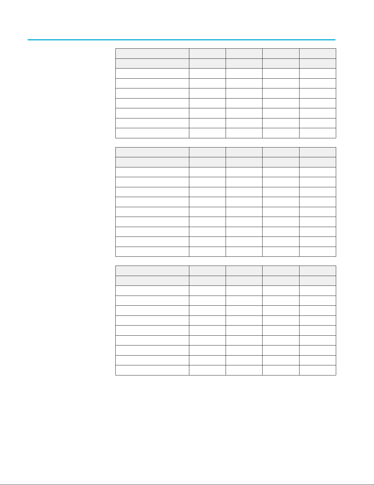
Specifications (MSO70000C/DX, DPO70000C/DX, and DPO7000C series) Vertical system analog channels
(cont.)
40 GS/s
Step gain 2.5 GHz 0.5 GHz 0.25 GHz 0.02 GHz
100 mV/div 6.3 mV 3.8 mV 3.2 mV 3.0 mV
50 mV/div 2.4 mV 1.75 mV 1.6 mV 1.5 mV
20 mV/div 1.07 mV 0.7 mV 0.63 mV 0.595 mV
10 mV/div 0.61 mV 0.38 mV 0.32 mV 0.3 mV
5 mV/div 0.41 mV 0.24 mV 0.18 mV 0.151 mV
2 mV/div 0.19 mV 0.18 mV 0.115 mV 0.065 mV
1 mV/div 0.12 mV 0.12 mV 0.115 mV 0.045 mV
20 GS/s
Step gain 2.5 GHz 0.5 GHz 0.25 GHz 0.02 GHz
500 mV/div 23.0 mV 16.3 mV 14.5 mV 14.0 mV
200 mV/div 10.5 mV 6.9 mV 6.1 mV 5.8 mV
100 mV/div 6.25 mV 3.8 mV 3.2 mV 3.0 mV
50 mV/div 2.4 mV 1.75 mV 1.6 mV 1.5 mV
20 mV/div 1.04 mV 0.7 mV 0.63 mV 0.595 mV
10 mV/div 0.605 mV 0.38 mV 0.32 mV 0.3 mV
5 mV/div 0.4 mV 0.24 mV 0.18 mV 0.151 mV
2 mV/div 0.19 mV 0.18 mV 0.115 mV 0.065 mV
1 mV/div 0.12 mV 0.12 mV 0.115 mV 0.045 mV
10 GS/s
Step gain 2.5 GHz 0.5 GHz 0.25 GHz 0.02 GHz
500 mV/div 22.8 mV 16.3 mV 14.5 mV 14.0 mV
200 mV/div 10.4 mV 6.9 mV 6.1 mV 5.8 mV
100 mV/div 6.15 mV 3.8 mV 3.2 mV 3.0 mV
50 mV/div 2.4 mV 1.75 mV 1.6 mV 1.5 mV
20 mV/div 1.035 mV 0.7 mV 0.63 mV 0.595 mV
10 mV/div 0.59 mV 0.38 mV 0.32 mV 0.3 mV
5 mV/div 0.395 mV 0.24 mV 0.18 mV 0.151 mV
2 mV/div 0.19 mV 0.18 mV 0.115 mV 0.065 mV
1 mV/div 0.12 mV 0.12 mV 0.115 mV 0.045 mV
40 MSO70000C/DX, DPO70000C/DX, DPO7000C, MSO5000/B, DPO5000/B Series
Page 53
Vertical system analog channels (cont.) Specifications (MSO70000C/DX, DPO70000C/DX, and DPO7000C
series)
DPO7254C Enhanced
bandwidth
40 GS/s
Step gain 2.5 GHz 2.0 GHz 1.0 GHz 0.5 GHz
500 mV/div 19.7 mV 16.2 mV 12.1 mV 9.9 mV
200 mV/div 8.71 mV 6.97 mV 4.97 mV 4.0 mV
100 mV/div 5.23 mV 4.25 mV 2.97 mV 2.36 mV
50 mV/div 2.0 mV 1.64 mV 1.23 mV 1.03 mV
20 mV/div 0.866 mV 0.707 mV 0.528 mV 0.431 mV
10 mV/div 0.523 mV 0.425 mV 0.297 mV 0.236 mV
5 mV/div 0.343 mV 0.349 mV 0.21 mV 0.154 mV
2 mV/div 0.135 mV 0.135 mV 0.135 mV 0.135 mV
1 mV/div 0.095 mV 0.095 mV 0.095 mV 0.095 mV
20 GS/s
Step gain 2.5 GHz 2.0 GHz 1.0 GHz 0.5 GHz
500 mV/div 19.5 mV 16.1 mV 12.0 mV 9.8 mV
200 mV/div 8.7 mV 7.05 mV 5.1 mV 4.0 mV
100 mV/div 5.15 mV 4.2 mV 2.95 mV 2.35 mV
50 mV/div 2.0 mV 1.65 mV 1.25 mV 1.05 mV
20 mV/div 0.855 mV 0.71 mV 0.52 mV 0.425 mV
10 mV/div 0.515 mV 0.42 mV 0.295 mV 0.235 mV
5 mV/div 0.34 mV 0.345 mV 0.21 mV 0.155 mV
2 mV/div 0.135 mV 0.135 mV 0.135 mV 0.135 mV
1 mV/div 0.095 mV 0.095 mV 0.095 mV 0.095 mV
10 GS/s
Step gain 2.5 GHz 2.0 GHz 1.0 GHz 0.5 GHz
500 mV/div 20.2 mV 16.7 mV 12.5 mV 10.3 mV
200 mV/div 8.9 mV 7.3 mV 5.3 mV 4.16 mV
100 mV/div 5.3 mV 4.3 mV 3.05 mV 2.4 mV
50 mV/div 2.1 mV 1.7 mV 1.3 mV 1.1 mV
20 mV/div 0.88 mV 0.74 mV 0.55 mV 0.435 mV
10 mV/div 0.52 mV 0.43 mV 0.3 mV 0.24 mV
5 mV/div 0.345 mV 0.33 mV 0.21 mV 0.155 mV
2 mV/div 0.135 mV 0.135 mV 0.135 mV 0.135 mV
1 mV/div 0.095 mV 0.095 mV 0.095 mV 0.095 mV
MSO70000C/DX, DPO70000C/DX, DPO7000C, MSO5000/B, DPO5000/B Series 41
Page 54
Specifications (MSO70000C/DX, DPO70000C/DX, and DPO7000C series) Vertical system analog channels
(cont.)
DPO7254C Without enhanced
bandwidth
40 GS/s
Step gain 2.5 GHz 0.5 GHz 0.25 GHz 0.02 GHz
500 mV/div 22.7 mV 16.4 mV 15.0 mV 14.5 mV
200 mV/div 9.84 mV 6.97 mV 6.2 mV 5.8 mV
100 mV/div 5.89 mV 3.74 mV 3.2 mV 2.9 mV
50 mV/div 2.31 mV 1.69 mV 1.55 mV 1.45 mV
20 mV/div 0.964 mV 0.697 mV 0.63 mV 0.59 mV
10 mV/div 0.574 mV 0.379 mV 0.325 mV 0.295 mV
5 mV/div 0.4 mV 0.231 mV 0.175 mV 0.145 mV
2 mV/div 0.19 mV 0.195 mV 0.12 mV 0.065 mV
1 mV/div 0.12 mV 0.12 mV 0.12 mV 0.045 mV
20 GS/s
Step gain 2.5 GHz 0.5 GHz 0.25 GHz 0.02 GHz
500 mV/div 21.8 mV 16.0 mV 15.0 mV 14.5 mV
200 mV/div 9.6 mV 6.8 mV 6.2 mV 5.8 mV
100 mV/div 5.7 mV 3.65 mV 3.2 mV 2.9 mV
50 mV/div 2.25 mV 1.65 mV 1.55 mV 1.45 mV
20 mV/div 0.94 mV 0.68 mV 0.63 mV 0.49 mV
10 mV/div 0.56 mV 0.37 mV 0.325 mV 0.295 mV
5 mV/div 0.38 mV 0.225 mV 0.175 mV 0.145 mV
2 mV/div 0.19 mV 0.195 mV 0.12 mV 0.065 mV
1 mV/div 0.12 mV 0.12 mV 0.12 mV 0.045 mV
10 GS/s
Step gain 2.5 GHz 0.5 GHz 0.25 GHz 0.02 GHz
500 mV/div 21.8 mV 16.0 mV 15.0 mV 15.5 mV
200 mV/div 9.6 mV 6.8 mV 6.2 mV 5.8 mV
100 mV/div 5.65 mV 3.65 mV 3.2 mV 2.9 mV
50 mV/div 2.2 mV 1.65 mV 1.55 mV 1.45 mV
20 mV/div 0.94 mV 0.68 mV 0.63 mV 0.59 mV
10 mV/div 0.56 mV 0.37 mV 0.325 mV 0.295 mV
5 mV/div 0.37 mV 0.225 mV 0.175 mV 0.145 mV
2 mV/div 0.19 mV 0.195 mV 0.12 mV 0.065 mV
1 mV/div 0.12 mV 0.12 mV 0.12 mV 0.045 mV
42 MSO70000C/DX, DPO70000C/DX, DPO7000C, MSO5000/B, DPO5000/B Series
Page 55

Vertical system analog channels (cont.) Specifications (MSO70000C/DX, DPO70000C/DX, and DPO7000C
series)
DPO7104C Enhanced
bandwidth
20 GS/s
Step gain 1.0 GHz 0.5 GHz
500 mV/div 13.2 mV 9.7 mV
200 mV/div 5.57 mV 3.93 mV
100 mV/div 3.27 mV 2.24 mV
50 mV/div 1.36 mV 0.98 mV
20 mV/div 0.574 mV 0.408 mV
10 mV/div 0.328 mV 0.232 mV
5 mV/div 0.229 mV 0.16 mV
2 mV/div 0.135 mV 0.135 mV
1 mV/div 0.095 mV 0.095 mV
10 GS/s
Step gain 1.0 GHz 0.5 GHz
500 mV/div 14.7 mV 10.3 mV
200 mV/div 6.09 mV 4.34 mV
100 mV/div 3.55 mV 2.38 mV
50 mV/div 1.53 mV 1.05 mV
20 mV/div 0.625 mV 0.441 mV
10 mV/div 0.350 mV 0.24 mV
5 mV/div 0.236 mV 0.16 mV
2 mV/div 0.135 mV 0.135 mV
1 mV/div 0.095 mV 0.095 mV
5 GS/s
Step gain 1.0 GHz 0.5 GHz
500 mV/div 15.9 mV 10.7 mV
200 mV/div 6.71 mV 4.48 mV
100 mV/div 3.74 mV 2.46 mV
50 mV/div 1.68 mV 1.1 mV
20 mV/div 0.682 mV 0.454 mV
10 mV/div 0.378 mV 0.247 mV
5 mV/div 0.241 mV 0.16 mV
2 mV/div 0.135 mV 0.135 mV
1 mV/div 0.095 mV 0.095 mV
MSO70000C/DX, DPO70000C/DX, DPO7000C, MSO5000/B, DPO5000/B Series 43
Page 56

Specifications (MSO70000C/DX, DPO70000C/DX, and DPO7000C series) Vertical system analog channels
(cont.)
DPO7104C Without enhanced
bandwidth
20 GS/s
Step gain 1.0 GHz 0.5 GHz 0.025 GHz 0.02 GHz
500 mV/div 16.2 mV 15.2 mV 14.0 mV 13.3 mV
200 mV/div 6.8 mV 6.3 mV 5.7 mV 5.3 mV
100 mV/div 3.7 mV 3.4 mV 3.0 mV 2.8 mV
50 mV/div 1.7 mV 1.6 mV 1.45 mV 1.4 mV
20 mV/div 0.7 mV 0.64 mV 0.58 mV 0.55 mV
10 mV/div 0.38 mV 0.35 mV 0.3 mV 0.285 mV
5 mV/div 0.25 mV 0.21 mV 0.17 mV 0.14 mV
2 mV/div 0.15 mV 0.15 mV 0.1 mV 0.065 mV
1 mV/div 0.11 mV 0.11 mV 0.11 mV 0.04 mV
10 GS/s
Step gain 1.0 GHz 0.5 GHz 0.025 GHz 0.02 GHz
500 mV/div 16.2 mV 15.2 mV 14.0 mV 13.3 mV
200 mV/div 6.8 mV 6.3 mV 5.7 mV 5.3 mV
100 mV/div 3.7 mV 3.4 mV 3.0 mV 2.8 mV
50 mV/div 1.7 mV 1.6 mV 1.45 mV 1.4 mV
20 mV/div 0.7 mV 0.64 mV 0.58 mV 0.55 mV
10 mV/div 0.38 mV 0.35 mV 0.3 mV 0.285 mV
5 mV/div 0.25 mV 0.21 mV 0.17 mV 0.14 mV
2 mV/div 0.15 mV 0.15 mV 0.1 mV 0.065 mV
1 mV/div 0.11 mV 0.11 mV 0.11 mV 0.04 mV
5 GS/s
Step gain 1.0 GHz 0.5 GHz 0.025 GHz 0.02 GHz
500 mV/div 16.2 mV 16.2 mV 14.0 mV 13.3 mV
200 mV/div 6.8 mV 6.3 mV 5.7 mV 5.3 mV
100 mV/div 3.7 mV 3.4 mV 3.0 mV 2.8 mV
50 mV/div 1.7 mV 1.6 mV 1.45 mV 1.4 mV
20 mV/div 0.7 mV 0.64 mV 0.58 mV 0.550 mV
10 mV/div 0.38 mV 0.35 mV 0.3 mV 0.285 mV
5 mV/div 0.25 mV 0.21 mV 0.17 mV 0.14 mV
2 mV/div 0.15 mV 0.15 mV 0.1 mV 0.065 mV
1 mV/div 0.11 mV 0.11 mV 0.11 mV 0.04 mV
44 MSO70000C/DX, DPO70000C/DX, DPO7000C, MSO5000/B, DPO5000/B Series
Page 57
Vertical system analog channels (cont.) Specifications (MSO70000C/DX, DPO70000C/DX, and DPO7000C
series)
DPO7054C Enhanced
bandwidth
10 GS/s
Step gain 0.5 GHz
500 mV/div 11.9 mV
200 mV/div 5.0 mV
100 mV/div 2.75 mV
50 mV/div 1.2 mV
20 mV/div 0.5 mV
10 mV/div 0.28 mV
5 mV/div 0.185 mV
2 mV/div 0.11 mV
1 mV/div 0.09 mV
5 GS/s
Step gain 0.5 GHz
500 mV/div 13.0 mV
200 mV/div 5.35 mV
100 mV/div 2.95 mV
50 mV/div 1.35 mV
20 mV/div 0.54 mV
10 mV/div 0.3 mV
5 mV/div 0.19 mV
2 mV/div 0.11 mV
1 mV/div 0.09 mV
DPO7054C Without enhanced
bandwidth
2.5 GS/s
Step gain 0.5 GHz
500 mV/div 15.0 mV
200 mV/div 6.2 mV
100 mV/div 3.35 mV
50 mV/div 1.56 mV
20 mV/div 0.63 mV
10 mV/div 0.375 mV
5 mV/div 0.205 mV
2 mV/div 0.11 mV
1 mV/div 0.09 mV
10 GS/s
Step gain 0.5 GHz 0.025 GHz 0.02 GHz
500 mV/div 15.1 mV 14.0 mV 13.2 mV
200 mV/div 6.35 mV 5.7 mV 5.4 mV
100 mV/div 3.4 mV 2.95 mV 2.75 mV
MSO70000C/DX, DPO70000C/DX, DPO7000C, MSO5000/B, DPO5000/B Series 45
Page 58

Specifications (MSO70000C/DX, DPO70000C/DX, and DPO7000C series) Vertical system analog channels
(cont.)
10 GS/s
Step gain 0.5 GHz 0.025 GHz 0.02 GHz
50 mV/div 1.6 mV 1.45 mV 1.38 mV
20 mV/div 0.645 mV 0.58 mV 0.55 mV
10 mV/div 0.34 mV 0.3 mV 0.277 mV
5 mV/div 0.21 mV 0.165 mV 0.141 mV
2 mV/div 0.13 mV 0.1 mV 0.062 mV
1 mV/div 0.096 mV 0.097 mV 0.04 mV
5 GS/s
Step gain 0.5 GHz 0.025GHz 0.02 GHz
500 mV/div 15.1 mV 14.0 mV 13.2 mV
200 mV/div 6.35 mV 5.7 mV 5.4 mV
100 mV/div 3.4 mV 2.95 mV 2.75 mV
50 mV/div 1.6 mV 1.45 mV 1.38 mV
20 mV/div 0.645 mV 0.58 mV 0.55 mV
10 mV/div 0.34 mV 0.3 mV 0.277 mV
5 mV/div 0.21 mV 0.165 mV 0.141 mV
2 mV/div 0.13 mV 0.1 mV 0.062 mV
1 mV/div 0.096 mV 0.097 mV 0.04 mV
2.5 GS/s
Step gain 0.5 GHz 0.025GHz 0.02 GHz
500 mV/div 15.1 mV 14.0 mV 13.2 mV
200 mV/div 6.35 mV 5.7 mV 5.4 mV
100 mV/div 3.4 mV 2.95 mV 2.75 mV
50 mV/div 1.6 mV 1.45 mV 1.38 mV
20 mV/div 0.645 mV 0.58 mV 0.55 mV
10 mV/div 0.34 mV 0.3 mV 0.277 mV
5 mV/div 0.21 mV 0.165 mV 0.141 mV
2 mV/div 0.13 mV 0.1 mV 0.062 mV
1 mV/div 0.096 mV 0.097 mV 0.04 mV
46 MSO70000C/DX, DPO70000C/DX, DPO7000C, MSO5000/B, DPO5000/B Series
Page 59

Vertical system analog channels (cont.) Specifications (MSO70000C/DX, DPO70000C/DX, and DPO7000C
series)
Channel-to-channel crosstalk
(channel isolation)
>20 GHz models, typical Input frequency range (up to the rated bandwidth). Assumes two channels with the same scale and
bandwidth settings.
0 to 9 GHz ≥ 120:1 isolation
>9 to 12 GHz ≥ 80:1 isolation
>12 to 15 GHz ≥ 50:1 isolation
>15 to 20 GHz ≥ 25:1 isolation
>20 to 33 GHz ≥ 20:1 isolation
≥ 4 GHz, ≤20 GHz models,
typical
<4 GHz models, typical RMS voltage ratio of ≥ 100:1 at ≤ 100 MHz and ≥ 30:1 at > 100 MHz up to 2.5 GHz, and
Delay between channels, BWE,
typical
>20 GHz models ≤ 1 ps between any two channels at any gain setting at 25 °C ±5 °C. Derate linearly to ≤ 3 ps at
Delay between channels, full
bandwidth, equivalent time, typical
>20 GHz models ≤ 3 ps between any two channels at any gain setting at 25 °C.
≥ 4 GHz, ≤20 GHz models ≤ 10 ps between any two channels with equal volts/div and coupling settings.
Input frequency range (up to the rated bandwidth). Assumes two channels with the same scale and
bandwidth settings.
0 to 10 GHz ≥ 120:1 isolation
>10 GHz to 12 GHz ≥ 80:1 isolation
>12 GHz to 15 GHz ≥ 50:1 isolation
>15 GHz to 20 GHz ≥ 25:1 isolation
≥20:1 above 2.5 GHz
5 °C and 45 °C.
≤ 10 ps for any two channels at any gain setting over temperature.
≤ 10 ps delay change when enabling and disabling Channel Equalization (DSP matching).
Delay between channels, typical
<4 GHz models
Internal probe power <4 GHz
models
Probe power per probe, <4 GHz
models
≤ 100 ps between any two channels with the same scale and coupling settings with input
impedance set to 50 Ω, DC coupling and scale set at or above 10 mV/div.
50 W maximum
Voltage Maximum Amperage Voltage Tolerance
5 V 50 mA ± 5%
12 V 1 A ±10%
MSO70000C/DX, DPO70000C/DX, DPO7000C, MSO5000/B, DPO5000/B Series 47
Page 60

Specifications (MSO70000C/DX, DPO70000C/DX, and DPO7000C series)
Horizontal and acquisition system
Real-time sample rate range
Number of channels
acquired
MSO/DPO70804C
MSO/DPO70604C
MSO/DPO70404C
MSO/DPO73304DX
MSO/DPO72504DX
MSO/DPO72304DX
MSO/DPO72004C
MSO/DPO71604C
MSO/DPO71254C
DPO7354C and
DPO7254C
DPO7104C 1 20 GS/s 40 GS/s
DPO7054C 1 20 GS/s
All channels Up to 25 GS/s
All channels Up to 50 GS/s
Two channels Up to 100 GS
1 40 GS/s
2 20 GS/s
3 or 4 10 GS/s
2 10 GS/s 20 GS/s
3 or 4 5 GS/s 10 GS/s
2 10 GS/s
3 or 4 5 GS/s
Sample rate, maximum
(Standard) (Option 2SR)
Equivalent-time sample rate or
interpolated waveform rate range
≥4 GHz models Up to 5 TS/s and 0.2 ps trigger placement resolution
<4 GHz models Up to 4 TS/s
Maximum record length, sample
mode, ≥4 GHz models
Equivalent-time acquisition can be enabled or disabled. When disabled, waveforms are interpolated
at the fastest time base settings.
The maximum record length depends on the installed record length options. Maximum record
length is less in serial trigger mode, hi-res mode, or when using the FIR filter.
Option 2XL installed
(standard on DPO70000C/DX Series)
Option 5XL installed
(standard on MSO70000C/DX Series)
Option 10XL installed 125,000,000 points (all channels)
Option 20XL installed 250,000,000 points (all channels)
Option 50XL installed (DX models only) 500,000,000 points (all channels), 1 G on 1–
31,250,000 points
62,500,000 points (all channels)
2 channels at 50 GS/s and 100 GS/s sample
rates or greater (interpolated or equivalent time)
48 MSO70000C/DX, DPO70000C/DX, DPO7000C, MSO5000/B, DPO5000/B Series
Page 61

Horizontal and acquisition system (cont.) Specifications (MSO70000C/DX, DPO70000C/DX, and DPO7000C
series)
Maximum record length, sample
mode <4 GHz models
Standard, DPO7354C and
DPO7254C
DPO7104C
DPO7054C
Option 2RL installed,
DPO7354C and DPO7254C
DPO7104C
DPO7054C
The maximum record length depends on the number of active channels and the record length
options installed. Maximum record length is less in serial trigger mode, hi-res mode or when using
the FIR filter.
10 GS/s
20 GS/s or less
40 GS/s or less
5 GS/s
10 GS/s or less
20 GS/s or less
2.5 GS/s
5 GS/s or less
10 GS/s or less
10 GS/s
20 GS/s or less
40 GS/s or less
5 GS/s
10 GS/s or less
20 GS/s or less
2.5 GS/s
5 GS/s or less
10 GS/s or less
12,500,000 points (3 or 4 channels)
25,000,000 points (2 channels)
50,000,000 points (1 channel)
12,500,000 points (3 or 4 channels)
25,000,000 points (2 channels)
50,000,000 points (1 channel)
12,500,000 points (3 or 4 channels)
25,000,000 points (2 channels)
50,000,000 points (1 channel)
25,000,000 points (3 or 4 channels)
50,000,000 points (2 channels only)
125,000,000 points (1 channel only)
25,000,000 points (3 or 4 channels)
50,000,000 points (2 channels only)
125,000,000 points (1 channel only)
25,000,000 points (3 or 4 channels)
50,000,000 points (2 channels only)
125,000,000 points (1 channel only)
Option 5RL installed,
DPO7354C and DPO7254C
DPO7104C
DPO7054C
Option 10RL installed,
DPO7354C and DPO7254C
Maximum record length, HiRes
mode
10 GS/s
20 GS/s or less
40 GS/s or less
5 GS/s
10 GS/s or less
20 GS/s or less
2.5 GS/s
5 GS/s or less
10 GS/s or less
10 GS/s
20 GS/s or less
40 GS/s or less
Half the record length of sample mode
50,000,000 points (3 or 4 channels)
125,000,000 points (2 channels only)
250,000,000 points (1 channel only)
50,000,000 points (3 or 4 channels)
125,000,000 points (2 channels only)
250,000,000 points (1 channel only)
50,000,000 points (3 or 4 channels)
125,000,000 points (2 channels only)
250,000,000 points (1 channel only)
125,000,000 points (3 or 4 channels)
250,000,000 points (2 channels only)
500,000,000 points (1 channel only)
MSO70000C/DX, DPO70000C/DX, DPO7000C, MSO5000/B, DPO5000/B Series 49
Page 62

Specifications (MSO70000C/DX, DPO70000C/DX, and DPO7000C series) Horizontal and acquisition system
(cont.)
Seconds division range ≥4 GHz models, Fastest sweep speed is 20 ps per division
<4 GHz models
DPO7354
C,
DPO7254
C
Horizontal
mode
Automatic 25 ps -
ConstantSR25 ps -
Manual 25 ps -
Record
Length
1 K 10 K 100 K 1 M 10 M 100 M 400/500 M
20 s
20 s
40 s
250 ps 200 s
250 ps 200 s
250 ps 400 s
2.5 ns 1ks
2.5 ns 1ks
2.5 ns 4ks
50 ns 1 ks
50 ns 1 ks
25 ns 40 ks
500 ns 1 ks
500 ns 1 ks
250 ns 400 ks
5 us - 1 ks 5 us - 1 ks
5 us - 1 ks 10 us -
1 ks
2.5 us 4 Ms
12.5 us -
8.19 Ms
DPO7104
C,
DPO7054
C
Horizontal
mode
Automatic 25 ps -
ConstantSR25 ps -
Manual 25 ps -
Acquisition update rate, typical
≥4 GHz models Fast Acquisition on: 300,000 waveforms per second maximum
<4 GHz models Fast Acquisition on: 250,000 waveforms per second maximum
Time base delay time range 5 ns to 250 s
Internal time-base reference
frequency
10 MHz
Electronically adjustable over about ±5 ppm.
Record
Length
1 K 10 K 100 K 1 M 10 M 100 M 200/250 M
20 s
20 s
40 s
250 ps 200 s
250 ps 200 s
250 ps 400 s
2.5 ns 1ks
2.5 ns 1ks
2.5 ns 4ks
50 ns 1 ks
50 ns 1 ks
25 ns 40 ks
500 ns 1 ks
500 ns 1 ks
250 ns 400 ks
5 us - 1 ks 5 us - 1 ks
5 us - 1 ks 10 us -
1 ks
2.5 us 4Ms
5 us - 8 Ms
Long term sample rate
accuracy
<4 GHz models ± 2.5 ppm initial accuracy. Aging < 1 ppm per year. Applies only when using the internal reference.
≥4 GHz models ± 1.5 ppm initial accuracy. Aging < 1 ppm per year. Applies only when using the internal reference.
50 MSO70000C/DX, DPO70000C/DX, DPO7000C, MSO5000/B, DPO5000/B Series
Page 63

Horizontal and acquisition system (cont.) Specifications (MSO70000C/DX, DPO70000C/DX, and DPO7000C
series)
Timing jitter (aperture uncertainty),
typical
>20 GHz models Measured at the maximum sample rate.
External Reference Low with ~0 dBm input drive at 10 MHz
<250 fs rms for record durations less than 10 μs
<350 fs rms for record durations less than 100 μs
<400 fs rms for record durations less than 10 ms
<600 fs rms for record durations less than 10 s
External Reference Hi with ~0 dBm input drive at 10 MHz
<250 fs rms for record durations less than 2 μs
<700 fs rms for record durations less than 10 s
For external reference in high (tracking) mode, the input reference must be low noise and the
edge slew rate must exceed 1.5 V/ns to achieve the typical jitter results.
Internal Reference
<250 fs rms for record durations less than 10 μs
<350 fs rms for record durations less than 100 μs
<400 fs rms for record durations less than 5 ms
In high (tracking) mode, the input reference must be low noise and the edge slew rate must
exceed 1.5 V/ns.
For internal reference, specification assumes no signal attached to the external reference input.
≥4 GHz, ≤20 GHz models Measured at the maximum BWE enabled bandwidth.
Total:
<250 fs rms for record durations less than 10 μs
<350 fs rms for record durations less than 100 μs
<650 fs rms for record durations less than 1 ms
<15 parts/trillion for record durations less than 60 s
<2 ps peak-to-peak for record durations less than 10 μs
<3 ps peak-to-peak for record durations less than 100 μs
<4 ps peak-to-peak for record durations less than 1 ms
This assumes either internal reference, or external reference in low (stable) mode. For external
reference in high (tracking) mode, the input reference must be low noise, and the edge slew rate
must exceed 1.5 V/ns to achieve the above approximate jitter results. For the general case,
external reference in high (tracking) mode, the specification is:
<250 fs rms for record durations less than 2 μs
You can approach the performance of internal reference using a clean reference signal with input
slew rate exceeding 1.5 V/ns. This is most easily achieved either with a square wave meeting that
slew rate or using a 100 MHz sine wave (≈2 Vp-p). This is required for the best possible
performance in synchronous sampling applications.
MSO70000C/DX, DPO70000C/DX, DPO7000C, MSO5000/B, DPO5000/B Series 51
Page 64

Specifications (MSO70000C/DX, DPO70000C/DX, and DPO7000C series) Horizontal and acquisition system
(cont.)
<4 GHz models Total:
<1 ps rms for record durations less than 10 μs.
<2.5 ps rms for record durations less than 30 ms.
<65 parts/trillion for record durations less than 10 s.
Jitter noise floor, typical, ≥4 GHz
models
MSO/DPO70000DX models
MSO/DPO70000C models
Applies to time periods as long as 10.0 μs. Typical jitter noise floor is measured at the maximum,
BWE enabled bandwidth:
MSO/DPO73304DX
MSO/DPO72504DX
MSO/DPO72304DX
<323 fs
<364 fs
<378 fs
Calculate the jitter noise floor (JNF) for a given instrument setting using the following formula:
Ntyp = typical input-referred noise spec (volts rms)
FN = 1.3 for instrument bandwidth ≤9 GHz; 1.5 for instrument bandwidth ≥10 GHz
SR = slew rate around the measurement
FI = (1.7 x 10⁻²)/sqrt(2) = 1.2 x 10⁻²
tr = rise time of the measurement edge
tj = timebase jitter or aperture uncertainty
TBA = timebase accuracy (2 ppm)
1
2
2
2
JNF
RMS
= (N
typ
× FN)2×
+ F
(
)
SR
I
× t
r
+ t
2
seconds
j
RMS
The interpolated sample rate of the waveform must be at least 25 times the bandwidth of the signal
being measured.
MSO/DPO72004C at 20 GHz 400 fs
MSO/DPO72004C,
300 fs
MSO/DPO71604C
at 16 GHz
MSO/DPO71254C at 12.5 GHz 300 fs
MSO/DPO70804C
450 fs
MSO/DPO70604C
MSO/DPO70404C
Calculate the jitter noise floor (JNF) for a given instrument setting using the following formula:
FS = full-scale setting (volts)
A = signal amplitude as a fraction of full-scale
trm = 10 - 90% displayed (or measured) rise time (seconds)
N = input-referred noise (volts rms)
tj = short term timing jitter (seconds rms)
JNF
RMS
N
=
FS × A
× t
2
2
+ t
rm
seconds
j
RMS
52 MSO70000C/DX, DPO70000C/DX, DPO7000C, MSO5000/B, DPO5000/B Series
Page 65

Horizontal and acquisition system (cont.) Specifications (MSO70000C/DX, DPO70000C/DX, and DPO7000C
series)
Timebase stability (sample rate
jitter or jitter noise floor), typical
<4 GHz models <1.0 ps rms for record durations less than 10 μs
Timebase jitter with external
reference, typical, ≥4 GHz models
Delta time measurement
accuracy, >20 GHz models
Total:
<2.5 ps rms for record durations less than 30 ms
<65 parts/trillion for record durations less than 10 s
≤3 ps
The formula to calculate the maximum delta-time measurement accuracy (DTAmax) for a given
instrument setting and input signal is given below (assumes insignificant signal content above
Nyquist and insignificant error due to aliasing, overdrive recovery and overdrive interpolation):
N
FN = 1.3 for instrument bandwidth ≤9 GHz; 1.5 for instrument bandwidth ≥10 GHz
SR1 = slew rate around 1st point in measurement (1st edge)
SR2 = slew rate around 2nd point in measurement (2nd edge)
TBA = timebase accuracy (2 ppm)
FI = 1.2 × 10⁻²
tr1 = rise time of first edge
r
t
2
tj = sample jitter/aperture uncertainty (about 250 fs for time durations less than 10 μs)
at 100 ms delay
RMS
= typical input-referred noise spec (volts rms)
typ
= rise time of second edge
t
= delta-time measurement (seconds)
reading
Peak-peak based on statistical accumulation of 1000 waveforms.
1
2
1
2
2
2
DTA
MAX
RMS is guaranteed regardless of data-gathering duration.
DTA
MAX
The term under the square-root sign is the stability and is due to time interval error (TIE). The
errors due to this term occur throughout a single-shot measurement. The second term is due to
both the absolute center-frequency accuracy and the center-frequency stability of the timebase and
varies between multiple single-shot measurements over the observation interval (the amount of
time from the first single-shot measurement to the final single-shot measurement). The observation
interval may not exceed 1 year.
Test at maximum bandwidth.
pk-pk
= 10 × (N
RMS
= 10 × (N
typ
typ
× FN)
TBA × t
× FN)
TBA × t
2
2
(
SR
reading
1
(
SR
reading
)
1
seconds
2
)
1
seconds
+
(
+
(
SR
SR
+ F
)
2
pk-pk
1
)
2
RMS
×(t
I
2
2
+ F
×(t
I
r1
2
r1
+ t
+ t
2
r2
2
r2
+ (2 × tj)2+
)
+ (2 × tj)2+
)
MSO70000C/DX, DPO70000C/DX, DPO7000C, MSO5000/B, DPO5000/B Series 53
Page 66

Specifications (MSO70000C/DX, DPO70000C/DX, and DPO7000C series) Horizontal and acquisition system
(cont.)
Test at 62.5 mVFS, 50 mVFS, 100 mVFS.
MSO/DPO73304DX at
100 GS/s, BWE on
MSO/DPO72504DX at
100 GS/s, BWE on
MSO/DPO72304DX at
100 GS/s, BWE on
MSO/DPO73304DX at
100 GS/s, BWE off, typical
MSO/DPO72504DX at
100 GS/s, BWE off, typical
MSO/DPO72304DX at
100 GS/s, BWE off, typical
6.25 mV/div, <10 ns measurement interval, 19.49 GHz, amplitude = 80% FS, 0.803 ps rms,
8.03 ps
pk-pk
50 mV/div, <10 ns measurement interval, 19.49 GHz, amplitude = 80% FS, 0.564 ps rms,
5.64 ps
pk-pk
100 mV/div, <10 ns measurement interval, 19.49 GHz, amplitude = 80% FS, 0.555 ps rms,
5.55 ps
pk-pk
6.25 mV/div, <10 ns measurement interval, 15.53 GHz, amplitude = 80% FS, 0.881 ps rms,
8.81 ps
pk-pk
50 mV/div, <10 ns measurement interval, 15.53 GHz, amplitude = 80% FS, 0.639 ps rms,
6.39 ps
pk-pk
100 mV/div, <10 ns measurement interval, 15.53 GHz, amplitude = 80% FS, 0.639 ps rms,
6.39 ps
pk-pk
6.25 mV/div, <10 ns measurement interval, 14.28 GHz, amplitude = 80% FS, 0.889 ps rms,
8.89 ps
pk-pk
50 mV/div, <10 ns measurement interval, 14.28 GHz, amplitude = 80% FS, 0.666 ps rms,
6.66 ps
pk-pk
100 mV/div, <10 ns measurement interval, 14.28 GHz, amplitude = 80% FS, 0.677 ps rms,
6.77 ps
pk-pk
6.25 mV/div, <10 ns measurement interval, 19.49 GHz, amplitude = 80% FS, 0.888 ps rms,
8.88 ps
pk-pk
50 mV/div, <10 ns measurement interval, 19.49 GHz, amplitude = 80% FS, 0.577 ps rms,
5.77 ps
pk-pk
100 mV/div, <10 ns measurement interval, 19.49 GHz, amplitude = 80% FS, 0.577 ps rms,
5.77 ps
pk-pk
6.25 mV/div, <10 ns measurement interval, 15.53 GHz, amplitude = 80% FS, 0.108 ps rms,
1.08 ps
pk-pk
50 mV/div, <10 ns measurement interval, 15.53 GHz, amplitude = 80% FS, 0.673 ps rms,
6.73 ps
pk-pk
100 mV/div, <10 ns measurement interval, 15.53 GHz, amplitude = 80% FS, 0.673 ps rms,
6.73 ps
pk-pk
6.25 mV/div, <10 ns measurement interval, 14.28 GHz, amplitude = 80% FS, 0.109 ps rms,
1.09 ps
pk-pk
50 mV/div, <10 ns measurement interval, 14.28 GHz, amplitude = 80% FS, 0.701 ps rms,
7.01 ps
pk-pk
100 mV/div, <10 ns measurement interval, 14.28 GHz, amplitude = 80% FS, 0.713 ps rms,
7.13 ps
pk-pk
Delta time measurement
accuracy ≥4 GHz, ≤20 GHz models
The formula to calculate the maximum delta-time measurement accuracy (DTAmax) for a given
instrument setting and input signal is given below (assumes insignificant signal content above
Nyquist and insignificant error due to aliasing, overdrive recovery and overdrive interpolation):
SR1 = slew rate around 1st point in measurement (1st edge)
SR2 = slew rate around 2nd point in measurement (2nd edge)
FN = 1.3 for instrument bandwidth ≤9 GHz; 1.5 for instrument bandwidth ≥10 GHz
54 MSO70000C/DX, DPO70000C/DX, DPO7000C, MSO5000/B, DPO5000/B Series
Page 67

Horizontal and acquisition system (cont.) Specifications (MSO70000C/DX, DPO70000C/DX, and DPO7000C
series)
Ntyp = typical input-referred noise spec (volts rms)
TBA = timebase accuracy (1.5 ppm)
treading = delta-time measurement (seconds)
Peak-peak based on statistical accumulation of 1000 waveforms.
1
2
1
DTA
MAX
RMS is guaranteed regardless of data-gathering duration.
DTA
MAX
The term under the square-root sign is the stability and is due to time interval error (TIE). The
errors due to this term occur throughout a single-shot measurement. The second term is due to
both the absolute center-frequency accuracy and the center-frequency stability of the timebase and
varies between multiple single-shot measurements over the observation interval (the amount of
time from the first single-shot measurement to the final single-shot measurement). The observation
interval may not exceed 1 year.
pk-pk
RMS
= 10 × (N
= (N
typ
typ
× FN)
× FN)
TBA × t
2
(
SR
TBA × t
2
1
1
(
SR
reading
2
+
)
reading
)
1
1
(
SR
seconds
2
+
(
seconds
2
)
2
+ 1ps2+ (2 × 10⁻⁹× t
)
SR
2
pk-pk
+ 1ps2+ (2 × 10⁻⁹× t
RMS
reading
reading
)2+
)2+
MSO/DPO72004C at 500 GS/s
(IT mode), BWE off
MSO/DPO71604C at 500 GS/s
(IT mode), BWE off
MSO/DPO71254C at 500 GS/s
(IT mode), BWE off
MSO/DPO70804C at 500 GS/s
(IT mode), BWE off
Test at maximum bandwidth. Test at 10 mV, 50 mV, 100 mV.
10 mV/div, <10 ns measurement interval, 9.94 GHz, amplitude = 80% FS, 1.280 ps rms,
12.80 ps
50 mV/div, <10 ns measurement interval, 9.94 GHz, amplitude = 80% FS, 1.172 ps rms,
11.72 ps
100 mV/div, <10 ns measurement interval, 9.94 GHz, amplitude = 80% FS, 1.186 ps rms,
11.86 ps
10 mV/div, <10 ns measurement interval, 9.94 GHz, amplitude = 80% FS, 1.280 ps rms,
12.80 ps
50 mV/div, <10 ns measurement interval, 9.94 GHz, amplitude = 80% FS, 1.172 ps rms,
11.72 ps
100 mV/div, <10 ns measurement interval, 9.94 GHz, amplitude = 80% FS, 1.186 ps rms,
11.86 ps
10 mV/div, <10 ns measurement interval, 7.76 GHz, amplitude = 80% FS, 1.304 ps rms,
13.04 ps
50 mV/div, <10 ns measurement interval, 7.76 GHz, amplitude = 80% FS, 1.201 ps rms,
12.01 ps
100 mV/div, <10 ns measurement interval, 7.76 GHz, amplitude = 80% FS, 1.205 ps rms,
12.05 ps
10 mV/div, <10 ns measurement interval, 4.97 GHz, amplitude = 80% FS, 1.462 ps rms,
14.62 ps
50 mV/div, <10 ns measurement interval, 4.97 GHz, amplitude = 80% FS, 1.295 ps rms,
12.95 ps
100 mV/div, <10 ns measurement interval, 4.97 GHz, amplitude = 80% FS, 1.336 ps rms,
13.36 ps
pk-pk
pk-pk
pk-pk
pk-pk
pk-pk
pk-pk
pk-pk
pk-pk
pk-pk
pk-pk
pk-pk
pk-pk
MSO70000C/DX, DPO70000C/DX, DPO7000C, MSO5000/B, DPO5000/B Series 55
Page 68

Specifications (MSO70000C/DX, DPO70000C/DX, and DPO7000C series) Horizontal and acquisition system
(cont.)
MSO/DPO70604C at 500 GS/s
(IT mode), BWE off
MSO/DPO70404C at 500 GS/s
(IT mode), BWE off
MSO/DPO72004C at 500 GS/s
(IT mode), 20 GHz, BWE on
MSO/DPO72004C at 500 GS/s
(IT mode), 18 GHz, BWE on
MSO/DPO72004C, MSO/
DPO71654C at 500 GS/s (IT
mode), 16 GHz, BWE on
MSO/DPO72004C, MSO/
DPO71654C, MSO/DPO71254C
at 500 GS/s (IT mode),
12.5 GHz, BWE on
MSO/DPO70804C at 500 GS/s
(IT mode), 8 GHz, BWE on
10 mV/div, <10 ns measurement interval, 3.73 GHz, amplitude = 80% FS, 1.625 ps rms,
16.25 ps
pk-pk
50 mV/div, <10 ns measurement interval, 3.73 GHz, amplitude = 80% FS, 1.427 ps rms,
14.27 ps
pk-pk
100 mV/div, <10 ns measurement interval, 3.73 GHz, amplitude = 80% FS, 1.463 ps rms,
14.63 ps
pk-pk
10 mV/div, <10 ns measurement interval, 2.48 GHz, amplitude = 80% FS, 2.022 ps rms,
20.22 ps
pk-pk
50 mV/div, <10 ns measurement interval, 2.48 GHz, amplitude = 80% FS, 1.762 ps rms,
17.62 ps
pk-pk
100 mV/div, <10 ns measurement interval, 2.48 GHz, amplitude = 80% FS, 1.821 ps rms,
18.21 ps
pk-pk
50 mV/div, <10 ns measurement interval, 9.94 GHz, amplitude = 80% FS, 1.260 ps rms,
12.60 ps
pk-pk
100 mV/div, <10 ns measurement interval, 9.94 GHz, amplitude = 80% FS, 1.432 ps rms,
14.32 ps
pk-pk
10 mV/div, <10 ns measurement interval, 9.94 GHz, amplitude = 80% FS, 1.336 ps rms,
13.36 ps
pk-pk
50 mV/div, <10 ns measurement interval, 9.94 GHz, amplitude = 80% FS, 1.182 ps rms,
11.82 ps
pk-pk
100 mV/div, <10 ns measurement interval, 9.94 GHz, amplitude = 80% FS, 1.234 ps rms,
12.34 ps
pk-pk
10 mV/div, <10 ns measurement interval, 9.94 GHz, amplitude = 80% FS, 1.219 ps rms,
12.19 ps
pk-pk
50 mV/div, <10 ns measurement interval, 9.94 GHz, amplitude = 80% FS, 1.154 ps rms,
11.54 ps
pk-pk
100 mV/div, <10 ns measurement interval, 9.94 GHz, amplitude = 80% FS, 1.159 ps rms,
11.59 ps
pk-pk
10 mV/div, <10 ns measurement interval, 7.45 GHz, amplitude = 80% FS, 1.333 ps rms,
13.33 ps
pk-pk
50 mV/div, <10 ns measurement interval, 7.45 GHz, amplitude = 80% FS, 1.212 ps rms,
12.12 ps
pk-pk
100 mV/div, <10 ns measurement interval, 7.45 GHz, amplitude = 80% FS, 1.228 ps rms,
12.287 ps
pk-p
k
10 mV/div, <10 ns measurement interval, 4.97 GHz, amplitude = 80% FS, 1.354 ps rms,
13.54 ps
pk-pk
50 mV/div, <10 ns measurement interval, 4.97 GHz, amplitude = 80% FS, 1.235 ps rms,
12.35 ps
pk-pk
100 mV/div, <10 ns measurement interval, 4.97 GHz, amplitude = 80% FS, 1.241 ps rms,
12.41 ps
pk-pk
56 MSO70000C/DX, DPO70000C/DX, DPO7000C, MSO5000/B, DPO5000/B Series
Page 69

Horizontal and acquisition system (cont.) Specifications (MSO70000C/DX, DPO70000C/DX, and DPO7000C
series)
MSO/DPO70804C, MSO/
DPO70604C at 500 GS/s (IT
mode), 6 GHz, BWE on
MSO/DPO70804C, MSO/
DPO70604C, MSO/DPO70404C
at 500 GS/s (IT mode), 4 GHz,
BWE on
Delta time measurement
accuracy <4 GHz models
10 mV/div, <10 ns measurement interval, 3.73 GHz, amplitude = 80% FS, 1.445 ps rms,
14.45 ps
pk-pk
50 mV/div, <10 ns measurement interval, 3.73 GHz, amplitude = 80% FS, 1.295 ps rms,
12.95 ps
pk-pk
100 mV/div, <10 ns measurement interval, 3.73 GHz, amplitude = 80% FS, 1.329 ps rms,
13.29 ps
pk-pk
10 mV/div, <10 ns measurement interval, 2.48 GHz, amplitude = 80% FS, 1.674 ps rms,
16.74 ps
pk-pk
50 mV/div, <10 ns measurement interval, 2.48 GHz, amplitude = 80% FS, 1.437 ps rms,
14.37 ps
pk-pk
100 mV/div, <10 ns measurement interval, 2.48 GHz, amplitude = 80% FS, 1.478 ps rms,
14.78 ps
pk-pk
For signals having amplitude greater than 5 divisions, reference level = 50%, filter set to sin(x)/x,
acquired at 10 mV/div or greater. The displayed risetime/sample interval must be greater than
1.4 but less than 4. Extra error will occur for two channel measurements due to channel to channel
skew. Peak specification is based on statistical accumulation of 1000 waveforms.
Single shot, sample or HiRes, full bandwidth (0.06/sample rate + 2.5 ppm x | reading |)RMS
± (0.30/(sample rate) + (2.5 ppm x | reading |))
peak
Average Mode, ≥100 averages, full bandwidth
± (2.5 ppm x | reading | + 4 ps)
selected.
MSO70000C/DX, DPO70000C/DX, DPO7000C, MSO5000/B, DPO5000/B Series 57
Page 70

Specifications (MSO70000C/DX, DPO70000C/DX, and DPO7000C series)
Trigger specifications
Trigger jitter DC coupled A edge
random holdoff, typical
≥4 GHz models 100 fs using enhanced trigger placement.
1 ps rms for low frequency, fast rise time signal, A edge, time holdoff = 30 μs
<4 GHz models 1.5 ps rms for low frequency, fast rise time signal
(DPO7104C and DPO7054C: 3 ps total trigger jitter.)
Edge trigger sensitivity DC
coupled, typical
≥4 GHz models
<4 GHz models
All sources, positive or negative edge, for vertical scale settings ≥10 mV/div and ≤1 V/div
Trigger Source Sensitivity
A Event trigger ≤ 4%FS from DC to 50 MHz
≤ 10%FS at 4 GHz
≤ 15%FS at 6 GHz
≤ 20%FS at 8 GHz
≤ 50%FS at 11 GHz
20%FS from DC to instrument bandwidth
(typical, enhanced trigger on, auto mode only for
frequencies above 8 GHz)
B Event trigger ≤ 4%FS from DC to 50 MHz
≤ 10%FS at 4 GHz
≤ 15%FS at 6 GHz
≤ 50%FS at 9 GHz
20%FS from DC to instrument bandwidth
(typical, enhanced trigger on, auto mode only for
frequencies above 6 GHz)
Auxiliary input 250 mV from DC to 50 MHz, increasing to
350 mV at 1 GHz
Trigger Source Sensitivity
Main and Delayed trigger ≤ 0.7 div from DC to 50 MHz
≤ 1.2 div at 2.5 GHz
≤ 2.5 div at 3.5 GHz with BWE on
Auxiliary input 1 MΩ: 250 mV from DC to 50 MHz, increasing to
350 mV at 250 MHz
50 Ω: 150 mV from DC to 50 MHz, increasing to
200 mV at 1.8 GHz
Video trigger, Ch1 - Ch4 0.6 to 2.5 divisions of video sync tip
Trigger sensitivity TPC, typical The minimum signal levels required for stable triggering of a waveform when the hardware is
incapable of doing so (excessive frequency, small input).
>20 GHz models
Trigger Source Sensitivity
A Event trigger, Ch1 – Ch4 20%×FS from DC to instrument bandwidth
B Event trigger, Ch1 – Ch4 20%×FS from DC to instrument bandwidth
58 MSO70000C/DX, DPO70000C/DX, DPO7000C, MSO5000/B, DPO5000/B Series
Page 71

Trigger specifications (cont.) Specifications (MSO70000C/DX, DPO70000C/DX, and DPO7000C series)
Edge trigger sensitivity not DC
coupled, typical
≥4 GHz models
<4 GHz models
All sources, positive or negative edge, for vertical scale settings ≥10 mV/div and ≤1 V/div
Trigger Coupling Sensitivity
NOISE REJ 15%FS from DC to 50 MHz
35%FS at 3 GHz
50%FS at 5 GHz
AC Same as DC-coupled limits for frequencies >
100 Hz, attenuates signals <100 Hz
HF REJ Same as DC-coupled limits for frequencies <
20 kHz, attenuates signals > 20 kHz
LF REJ Same as DC-coupled limits for frequencies >
200 kHz, attenuates signals < 200 kHz
Trigger coupling Sensitivity
NOISE REJ 3 times the DC-coupled limits
AC Same as DC-coupled limits for frequencies >
100 Hz, attenuates signals <100 Hz
HF REJ Same as DC-coupled limits for frequencies <
20 kHz, attenuates signals > 20 kHz
LF REJ Same as DC-coupled limits for frequencies >
200 kHz, attenuates signals < 200 kHz
Trigger level or threshold range
>20 GHz models
≥4 GHz, ≤20 GHz models
<4 GHz models
Trigger Source Range
Any channel ±100% FS from center of screen
Auxiliary input ±4.0 V
Line 0 V, Not settable
Trigger Source Range
Any channel ±120% FS from center of screen
Auxiliary input ±4.0 V
Line 0 V, Not settable
Trigger Source Range
Any channel ±12 divisions from center of screen
Auxiliary input ±5 V
Line Not settable
MSO70000C/DX, DPO70000C/DX, DPO7000C, MSO5000/B, DPO5000/B Series 59
Page 72

Specifications (MSO70000C/DX, DPO70000C/DX, and DPO7000C series) Trigger specifications (cont.)
Trigger level or threshold
accuracy, typical
≥4 GHz models
<4 GHz models
Trigger position error, typical Edge trigger, DC coupling, for signals having a slew rate at the trigger point of ≥ 0.5 divisions/ns
≥4 GHz models
<4 GHz models
Time range for time-qualified
triggers
≥4 GHz models
Edge trigger, DC coupled
Trigger Source Accuracy
Channel 1, 2, 3, or 4 ± [(2% | trigger level - net offset | ) + (3.5% FS)
+ offset accuracy]
Auxiliary Not specified
Trigger Source Accuracy
Channel 1, 2, 3, or 4 ± [(2% | deflection | ) + (0.7 divisions ×
Auxiliary Not specified
Acquisition mode Trigger Position Error
Sample, Average ± (1 waveform interval + 50 ps)
Peak Detect, Envelope ± (2 waveform intervals + 50 ps)
Acquisition mode Trigger Position Error
Sample, Average ± (1 waveform interval + 200 ps)
Peak Detect, Envelope ± (2 waveform intervals + 200 ps)
Setup/Hold Violation
Setup time
Hold time
Setup + hold time
Timeout 400 ps to 1 s
Time qualified window, outside >t 600 ps to 1 s
All other types 300 ps to 1 s
-100 ns to +100 ns
-1 ns to +100 ns
500 ps minimum
<4 GHz models 300 ps to 1 s
Time-qualified trigger timer
accuracy
≥4 GHz models
<4 GHz models
For Glitch, Width, Time qualified runt, Transition, or Setup/hold violation types
Time range Accuracy
Glitch and width triggering (300 ps to 1.0 ns typical)
<300 ns to 1.01 μs ±(3% of setting + 80 ps)
1.02 μs to 1 s ±(TB accuracy + 100 ns)
Other time-qualified types (300 ps to 1.0 ns typical)
<300 ps to 1.01 μs ±(5% of setting + 200 ps)
1.02 μs to 1 s ±(TB accuracy + 20 ns)
Time range Accuracy
<1 μs (<2 ns typical) ±(20% of setting + 0.5 ns)
1 μs to 1 s ±(0.01% of setting + 100 ns)
60 MSO70000C/DX, DPO70000C/DX, DPO7000C, MSO5000/B, DPO5000/B Series
Page 73
Trigger specifications (cont.) Specifications (MSO70000C/DX, DPO70000C/DX, and DPO7000C series)
Width and glitch trigger sensitivity,
typical
≥4 GHz models 15% x FS from DC to 1 GHz, not violating the minimum timing requirements for each type (for
vertical settings from 10 mV/div to 1 V/div at the input connector)
<4 GHz models 1.0 division from DC to 1 GHz (at input connector)
Width and glitch trigger minimum
timing requirements
≥4 GHz models
<4 GHz models
Runt trigger sensitivity, typical
≥4 GHz models 15% x FS from DC to 1 GHz, not violating the minimum timing requirements for each type (for
<4 GHz models 1.0 division (at input connector)
Runt trigger, minimum timing
requirements
≥4 GHz models
For vertical scale settings 10 mV/div and 1 V/div
Minimum
pulse width
Width and glitch types 150 ps 300 ps N.A. N.A.
Logic qualified width and glitch
types
Width type 225 ps 250 ps N.A. N.A.
Logic qualified width type 190 ps 250 ps 40 ps 175 ps
Glitch type 170 ps 250 ps N.A. N.A.
Logic qualified glitch type 100 ps 250 ps 40 ps 60 ps
vertical settings from 10 mV/div to 1 V/div at the input connector)
A runt event occurs at the end of the runt whether or not the runt was time qualified. Logic qualified
runt triggers require that the logic condition be true during the entire duration of the runt plus some
minimum amount of time after the runt event occurred.
Runt type 200 ps 300 ps
Logic qualified runt type 200 ps 300 ps 300 ps 300 ps
Time qualified runt type 476 ps 510 ps N.A. N.A.
Time and logic qualified runt
type
150 ps 300 ps 20 ps 40 ps
Minimum
pulse width
Minimum
pulse time
520 ps 360 ps 160 ps 105 ps
Minimum
rearm time
Minimum
rearm time
Minimum
rearm time
Setup time Hold time
Setup time Hold time
Setup time Hold time
<4 GHz models
Runt type 225 ps 250 ps N.A. N.A.
Time qualified runt type 360 ps 450 ps N.A. N.A.
Logic qualified runt type Runt width +
Time and logic qualified runt
type
Minimum
pulse time
150 ps
Runt width +
330 ps
Minimum
rearm time
250 ps 160 ps -16 ps
250 ps 160 ps 175 ps
Setup time Hold time
MSO70000C/DX, DPO70000C/DX, DPO7000C, MSO5000/B, DPO5000/B Series 61
Page 74

Specifications (MSO70000C/DX, DPO70000C/DX, and DPO7000C series) Trigger specifications (cont.)
Pattern and state trigger sensitivity
DC coupled, typical, ≥4 GHz
models
Logic and state trigger sensitivity
DC coupled, typical, <4 GHz
models
Logic and state trigger minimum
timing requirements, typical,
<4 GHz models
Video-type trigger formats and
field rates, <4 GHz models
Timeout trigger minimum timing
requirements
≥4 GHz models
15% x FS from DC to 1 GHz, not violating the minimum timing requirements for each type (for
vertical settings from 10 mV/div to 1 V/div at input connector)
1.0 division from DC to 1 GHz (for vertical settings from 10 mV/div to 1 V/div at input connector)
Minimum duration of logic state: 100 ps (10 GB/s). The minimum duration of the logic pattern
includes delay mismatch between channels.
Minimum pulse width Rearm time
Logic type 100 ps (10 GB/s) 100 ps
State type 500 ps 500 ps
Time qualified logic type 300 ps 500 ps
Triggers from negative sync composite video, field 1 or field 2 for interlaced systems, any field,
specific line, or any line for interlaced or non-interlaced systems. Supported systems include NTSC,
PAL, SECAM, and HDTV 1080/24sF, 1080p/25, 1080i/50, 1080i/60, 1080p/24, 720p/60, 480p/60.
Timeout event occurs after the signal has stayed in some state the minimum amount of time. Setup
and hold times are how long before and after the timeout event the logic level must remain valid in
order to generate a trigger.
Minimum
pulse width
Timeout type N.A. 300 ps + pulse
Logic qualified timeout type N.A. 300 ps + pulse
Minimum
rearm time
width
width
Setup time Hold time
N.A. N.A.
50 ps 50 ps
<4 GHz models
Minimum
pulse width
Timeout type 300 ps 500 ps + pulse
Logic qualified timeout type 300 ps 500 ps + pulse
Minimum
rearm time
width
width
Setup time Hold time
N.A. N.A.
200 ps 200 ps
62 MSO70000C/DX, DPO70000C/DX, DPO7000C, MSO5000/B, DPO5000/B Series
Page 75

Trigger specifications (cont.) Specifications (MSO70000C/DX, DPO70000C/DX, and DPO7000C series)
Window trigger minimum timing
requirements
≥4 GHz models
Window enters 150 ps 500 ps N.A. N.A.
Window exits 500 ps 150 ps N.A. N.A.
Logic qualified window enters 150 ps 500 ps N.A. N.A.
Logic qualified window exits 500 ps 150 ps N.A. N.A.
Window inside >t N.A. 500 ps N.A. N.A.
Window outside >t N.A. 150 ps N.A. N.A.
Minimum
pulse width
Minimum
rearm time
Setup time Hold time
<4 GHz models
Window 225 ps 300 ps N.A. N.A.
Logic qualified window 190 ps 300 ps -20 ps 0 ps
Transition trigger, minimum timing
requirements
≥4 GHz models
<4 GHz models
Transition trigger delta time range 1 ns to 1 s
Setup-Hold violation trigger, setup
and hold time ranges
The transition trigger event occurs at the end of the transition. The logic condition must be valid at
the moment the transition event occurs minus the setup time plus the hold time. Rearm time is the
time below the lower threshold and the time above the upper threshold. Neither time can be
violated.
Transition type 0 ps 500 ps N.A. N.A.
Logic qualified transition type 0 ps 500 ps 50 ps 50 ps
Transition type 0 ps 225 ps N.A. N.A.
Logic qualified transition type 330 ps 225 ps 225 ps 175 ps
Setup time -100 ns 100 ns
Hold time -1 ns 102 ns
Setup + hold time 500 ps
Minimum
pulse width
Minimum
pulse width
Minimum
pulse width
Minimum Maximum
Minimum
rearm time
Minimum
rearm time
Minimum
rearm time
Setup time Hold time
Setup time Hold time
Setup time Hold time
MSO70000C/DX, DPO70000C/DX, DPO7000C, MSO5000/B, DPO5000/B Series 63
Page 76

Specifications (MSO70000C/DX, DPO70000C/DX, and DPO7000C series) Trigger specifications (cont.)
Setup-hold time violation trigger,
minimum clock pulse widths,
typical
≥4 GHz models
Minimum time from active clock edge to
inactive edge
Hold times ≥ 0: Hold time + 550 ps 500 ps
Hold times <0: Hold time + 1.6 ns 500 ps
Minimum time from inactive clock edge to
active edge
<4 GHz models
Pattern and state trigger, minimum
timing requirements, typical,
≥4 GHz models
Period trigger sensitivity, typical
≥4 GHz models 1.5 divisions (at input connector)
<4 GHz models 1.0 division (at input connector)
B trigger after events minimum
timing requirements, typical
≥4 GHz models
Minimum time from active clock edge to
inactive edge
Hold times ≥ 0: Hold time + 500 ps 500 ps
Hold times <0: Hold time + 1.5 ns
The transition trigger event occurs at the end of the transition. The logic condition must be valid at
the moment the transition event occurs minus the setup time plus the hold time.
Pattern type 150 ps 200 ps N.A. N.A.
Time qualified pattern type 150 ps 300 ps N.A. N.A.
State type 1.7 GHz N.A. 25 ps 100 ps
Minimum pulse width Maximum counting frequency Minimum time between
140 ps 3.5 GHz 1 ns
Minimum
pulse width
Minimum time from inactive clock edge to
active edge
Minimum
rearm time
Setup time Hold time
channels
<4 GHz models
B trigger after events, event
counter range
≥4 GHz models 1 to 2,000,000,000
<4 GHz models 1 to 10,000,000
B trigger after time, time delay
range
≥4 GHz models 3.2 ns to 3 Ms
<4 GHz models 5 ns to 250 s
Minimum pulse width Maximum counting frequency Minimum time between
channels
200 ps 1 ns
64 MSO70000C/DX, DPO70000C/DX, DPO7000C, MSO5000/B, DPO5000/B Series
Page 77

Trigger specifications (cont.) Specifications (MSO70000C/DX, DPO70000C/DX, and DPO7000C series)
Variable A event trigger holdoff
range
Lowest frequency for successful
set level to 50%, typical
Trigger jitter (RMS)
≥4 GHz models 100 fs using enhanced Trigger placement. 1.0 ps RMS (typical) for low frequency, fast rise time
<4 GHz models 1.5 ps RMS (typical)
250 ns to 12 s + random holdoff
50 Hz
signal, A edge, time holdoff = 30 μs.
Serial trigger specifications
Low speed serial trigger, ≥4 GHz
models
Number of bits 128 bits
Baud rate limits 10 Mbits/s
High speed serial trigger number
of bits
≥4 GHz models 64 bits for NRZ data rates ≤ 1.25 GBaud
40 bits for 8b/10b data rates between 1.25 GBd and 6.25 GBd
<4 GHz models 64 bits
MSO70000C/DX, DPO70000C/DX, DPO7000C, MSO5000/B, DPO5000/B Series 65
Page 78

Specifications (MSO70000C/DX, DPO70000C/DX, and DPO7000C series) Serial trigger specifications (cont.)
High speed serial trigger, serial
word recognizer position accuracy
≥4 GHz models ± 200 ps
<4 GHz models
Serial trigger decoding types
≥4 GHz models
<4 GHz models NRZ
Acquisition mode
Sample, Average ± (1 waveform interval + 200 ps)
Peak Detect, Envelope ± (2 waveform intervals + 200 ps)
≤ 1.25 GB: NRZ
≤ 1.25 GB: 1.25 GB to 6.25 GB: 8B10B
Serial trigger baud rate limits
≥4 GHz models
Serial trigger baud rate limits,
<4 GHz models
NRZ Up to 1.25 GBd
8B10B, typical NRZ 8B10B encoded data at the following bit
rates:
1.25 GBd,
1.50 GBd,
1.57 GBd,
1.62 GBd,
1.65 GBd,
2.00 GBd,
2.50 GBd,
2.7 GBd,
3.00 GBd,
3.125 GBd,
3.2 GBd,
4.25 GBd,
4.80 GBd,
5.00 GBd,
5.4 GBd,
6.00 GBd,
6.25 GBd
Up to 1.25 GBd (Option PTM adds protocol trigger to DPO7000C Series)
Error detection jitter tolerance ≤ 0.4 UI of total jitter on the signal.
Clock recovery frequency range
≥4 GHz models, typical 1.5 MBaud to 3.125 GBaud. Above 1250 MHz, the clock is only available internally as a trigger
source. Below 1250 MHz, the clock is also available at the recovered clock output along with
regenerated data.
<4 GHz models 1.5 MBaud to 1.25 GBaud.
66 MSO70000C/DX, DPO70000C/DX, DPO7000C, MSO5000/B, DPO5000/B Series
Page 79

Serial trigger specifications (cont.) Specifications (MSO70000C/DX, DPO70000C/DX, and DPO7000C series)
Clock recovery jitter, typical
≥4 GHz models < 0.25% bit period + 2 ps rms for PRBS data patterns with 50% transition density.
< 0.25% bit period + 1.5 ps rms for repeating 0011 data patterns.
Bit rate Pattern Jitter (ps rms)
PRBS 0011
3.125 GBd 00110011 2.8 ps 2.3 ps
2.74 GBd 00110011 2.9 ps 2.4 ps
2.35 GBd 00110011 3.1 ps 2.6 ps
2.34 GBd 00110011 3.1 ps 2.6 ps
1.95 GBd 00110011 3.3 ps 2.8 ps
1.57 GBd 00110011 3.6 ps 3.1 ps
100 MBd 00110011 27 ps 27 ps
10 MBd 00110011 252 ps 252 ps
<4 GHz models 20 ps
20 ps
+ 1.25% Unit interval RMS for PRBS data patterns.
RMS
+ 1.25% Unit interval RMS for repeating 0011 data patterns. (Transition density of 50%).
RMS
Jitter increases by 1.4 every time the transition density is reduced by half.
28 ps
30 ps
+ 1.25% Unit interval RMS for 25% transition density.
RMS
+ 1.25% Unit interval RMS for 12.5% transition density.
RMS
Clock recovery tracking
acquisition range
≥4 GHz models ± 2% of requested baud, data rates below 1.25 GBaud.
± 0.25% of requested baud, data rates above 1.25 GBaud.
<4 GHz models ± 5% of requested baud
Minimum signal amplitude needed
for clock recovery, typical
≥4 GHz models 1 division peak-peak up to 1.25 GBd
1.5 divisions peak-peak above 1.25 GBd
Tri-level signals need 50% more pk-pk amplitude
<4 GHz models 1 division peak-peak up to 1.25 GBd
50% more peak-to-peak amplitude is required for tri-level signals.
Serial interface triggering
standards supported
<4 GHz models I2C, CAN, SPI, USB1.1, RS232/422/485/UART
MSO70000C/DX, DPO70000C/DX, DPO7000C, MSO5000/B, DPO5000/B Series 67
Page 80

Specifications (MSO70000C/DX, DPO70000C/DX, and DPO7000C series)
Digital acquisition specifications
Minimum signal amplitude
300 mV p-p; logic threshold centered in dynamic range of signal;
f ≤1.5 GHz for P6780
f ≤350 MHz for P6717A
Minimum detectable pulse width
(mainframe and logic probe),
typical
Number of probe channels 17
Number of digital acquisition
channels
Digital channel resolution 1 bit, either a 0 or a 1
Logic threshold range -2 V to +5 V
with P6780 probe -2 V to +4.5 V
with P6717A probe -1.5 V to +4.0 V
Logic threshold resolution 5 mV
Logic threshold accuracy (with
probe attached), typical
Single acquisition displayed timing
uncertainty between digital
channels with P6780 probe, typical
Without deskew 160 ps
After deskew 80 ps
<400 ps
16
≤3% of threshold setting ±75 mV
Number of digital channels
available for analog acquisition
iCapture bandwidth with general
purpose probe, typical
iCapture bandwidth with solder-in
differential probe, typical
iCapture rise time with solder-in
differential probe, typical
Position range of analog iCapture
channels
4. Any of the 16 acquisition channels + clock qualifier channel can be displayed in place of any
analog channel on the instrument
>300 MHz
>2.5 GHz
≤200 ps
±5 divisions
68 MSO70000C/DX, DPO70000C/DX, DPO7000C, MSO5000/B, DPO5000/B Series
Page 81

Digital acquisition specifications (cont.) Specifications (MSO70000C/DX, DPO70000C/DX, and DPO7000C
series)
iCapture DC analog accuracy
(mainframe and probe)
Gain ranges of analog channels
with probe
Digital channel comparison values 0, 1, or don't care
Word recognizer trigger functions
Combinational trigger AND, NAND, OR, NOR
Edge qualified combinational
trigger
Trigger toggle rate, typical ≥1.5 GHz
Single channel trigger jitter,
typical
iCapture trigger level range ± Full scale
iCapture trigger level accuracy 6% of trigger level +0.4 divisions
iCapture trigger sensitivity 5% of FS from DC to 0.5 GHz
±(5% of reading +0.2 division)
250 mV/div, 375 mV/div, 750 mV/div, 1.25 V/div, 1.88 V/div, 3.75 V/div
AND, NAND, OR, NOR qualified on the rising or falling edge, or either edge of CQ, the qualifying
channel
5 ps rms for A event edge trigger using low frequency, fast rise time signal
6% of FS from 0.15 GHz to 1 GHz
8% of FS from 1.01 GHz to 1.5 GHz
9% of FS from 1.51 GHz to 2.0 GHz
13% of FS from 2.0 GHz to 2.5 GHz
Low speed serial trigger threshold
accuracy, typical
Low speed serial trigger threshold
range
Maximum low speed serial trigger
toggle rate
Maximum digital acquisition
sample rate
Maximum record length, sample
mode
Standard 12.5 GS/s or less 10,000,000 points (all channels)
Option 2XL installed 12.5 GS/s or less 20,000,000 points (all channels)
Option 5XL installed 12.5 GS/s or less 50,000,000 points (all channels)
Option 10XL installed 12.5 GS/s or less 125,000,000 points (all channels)
Option 20XL installed 12.5 GS/s or less 250,000,000 points (all channels)
±(3% of setting ±125 mV) relative to the probe tip input
+20 mV/°C from the operating temperature at which SPC was run
-2 to +4.5 V with DI probe
-1.5 to +4 V with GP probe
I2C: 3.4 MHz
SPI: 4.25 MHz
12.5 GS/s
The maximum record length depends on the number of active channels and the installed record
length options. The maximum record length is less in serial trigger mode, hi-res mode, or when
using the FIR filter.
MSO70000C/DX, DPO70000C/DX, DPO7000C, MSO5000/B, DPO5000/B Series 69
Page 82

Specifications (MSO70000C/DX, DPO70000C/DX, and DPO7000C series)
Input-output port specifications
Auxiliary trigger input
characteristics and range
≥4 GHz models 50 Ω, ±4 V (DC plus peak AC)
MSO/DPO70000DX: 50 Ω, ±5 V (DC plus peak AC)
<4 GHz models 50 Ω, ± 5%; maximum input voltage ± 5 V (DC + peak AC)
1 MΩ, ±5%, 150 V CAT1. Derate at 20 dB/decade to 9 V RMS above 200 kHz
Auxiliary output logic polarity and
functionality
Auxiliary output logic levels
CH3 output voltage typical < 4 GHz
models
High speed serial data output baud
rate range
≥ 4 GHz models Fbaud ≤ 1250 MB. Output swing of 1010 repeating pattern at this baud will be at least 200 mV into
High speed serial clock output
frequency range
≥4 GHz models Peak-to-peak output swing at 625 MHz is at least 200 mV p-p into 50 Ω. Higher frequencies are
Default output is A trigger low true (a negative edge when the A trigger event occurs). You can also
program the output to A trigger high true, B trigger low or high true, disabled, force high, and force
low.
V
high V
out
≥2.5 V into 1 MΩ load,
≥1.0 V into 50 Ω load to ground
50 mV/div ± 20% into a 1 MΩ load
25 mV/div ±20% into a 50 Ω load
50 Ω.
further attenuated by approximately 6 dB per octave above 625 MHz.
Use AC or DC coupled 50 Ω termination; AC coupling the clock provides about 10% more
amplitude.
low (true)
out
≤0.7 V into 1 MΩ load
≤0.25 V into 50 Ω load to ground
High speed serial data and clock
output voltages, typical
≥4 GHz models Voh = -1.0 V
Vol = -1.7 V
Assumes a load impedance greater than 1 kΩ. (50 Ω source termination.)
If a 50 Ω or 75 Ω load is used, either use a DC blocking capacitor in series with the signal or
reference the termination to about -1.3 V. The signal amplitude will be correspondingly reduced.
70 MSO70000C/DX, DPO70000C/DX, DPO7000C, MSO5000/B, DPO5000/B Series
Page 83

Input-output port specifications (cont.) Specifications (MSO70000C/DX, DPO70000C/DX, and DPO7000C
series)
High speed serial data output
latency, typical
≥4 GHz models 11 ns ± 4 ns, plus the following synchronous latency depending on the data encoding:
35.5 clock cycles for NRZ, CMI, Manchester, and B-0-V decoded data.
36.5 clock cycles for NRZI decoded data.
39.5 clock cycles for B3ZS decoded data.
40.5 clock cycles for B4ZS decoded data.
42.5 clock cycles for B6ZS decoded data.
44.5 clock cycles for B8ZS decoded data.
Probe compensation output
step amplitude and offset
>20 GHz models 440 mV ± 22% into a 50 Ω load (Vol = -0.14 V, Voh = 0.3 V, typical)
810 mV ± 22% into a ≥10 kΩ load, (Vol = -0.25 V, Voh = 0.56 V, typical)
≥4 GHz, ≤20 GHz models 440 mV ± 22% into a 50 Ω load (Vol = -0.2 V to 0 V, Voh = 0.2 V to 0.4 V, typical)
810 mV ± 22% into a 10 kΩ load, (Vol = -0.4 V to 0 V, Voh = 0.4 V to 0.8 V)
<4 GHz models 1 V ± 1.5% into a ≥ 100 kΩ load (Vol = -1.0 V, Voh = 0 V typical)
Add 0.05%/°C for temperatures greater than or less than 25 °C
Probe compensation output step
frequency
≥4 GHz models 1 kHz ± 20%
<4 GHz models 1 kHz ± 5%
Probe calibration output step rise
time
≥4 GHz models 300 ps (10% to 90%) directly into an input channel. To deskew a probe, use a 50 Ω terminator in
series with the deskew fixture to minimize HF aberrations.
<4 GHz models ≤350 ps at 1 V, into a ≥20 KΩ load to ground.
≤1 ns at 2 V, into a 50 Ω load to ground.
To deskew a probe, use a 50 Ω terminator in series with the deskew fixture to minimize HF
aberrations.
Probe calibration output step
aberrations
Jitter of internal probe calibration
trigger
≤ ± 1% after the first 500 ns following the square wave transition. To deskew a probe, use a 50 Ω
terminator in series with the deskew fixture to minimize HF aberrations.
5 ps RMS
External reference input frequency,
typical
Run SPC whenever the external reference is more than 0.1% (1000 ppm) different than the
nominal reference or the reference at which SPC was last run.
MSO70000C/DX, DPO70000C/DX, DPO7000C, MSO5000/B, DPO5000/B Series 71
Page 84

Specifications (MSO70000C/DX, DPO70000C/DX, and DPO7000C series) Input-output port specifications
(cont.)
The timebase changes in correspondence to the fluctuations in the external reference.
≥4 GHz models 10 MHz, 100 MHz
The instrument scans for either 10 MHz or 100 MHz.
<4 GHz models 10 MHz
External reference input
sensitivity, typical
≥4 GHz models ≥ 200 mV
<4 GHz models ≥ 1.5 V
p-p
p-p
External reference input voltage,
maximum, typical
> 20 GHz models: 4 Vp-p
≤20 GHz models: 7 Vp-p
External reference input
impedance, typical
>20 GHz models Rin = 50 Ω
≥4 GHz, ≤20 GHz models Rin = 1.5 kΩ, Cin = 40 pF, measured at >100 kHz
<4 GHz models 385 Ω, Cin = 137 pF, measured at 10 MHz
External reference input frequency
variation tolerance, typical
>20 GHz models Low (stable) jitter mode: ± 10 ppm
High (tracking) mode: ± 1%
≥4 GHz, ≤20 GHz models Low (stable) jitter mode: ± 100 ppm
High (tracking) mode: ± 1%
Running SPC is required whenever the external reference is more than 0.1% (1000 ppm) different
from the nominal reference frequency or reference at which SPC was last run.
<4 GHz models 9.8 MHz to 10.2 MHz
Internal reference output
frequency
≥4 GHz models 10 MHz
<4 GHz models 10 MHz available at AUXOUT
Internal reference output voltage,
typical
≥4 GHz models > 750 mV peak-peak into 50 Ω
> 1.5 V peak-peak into 1 MΩ (internally AC coupled).
<4 GHz models
V
high V
out
≥2.5 V into open circuit,
≥1.0 V into 50 Ω load to ground
low (true)
out
≤0.7 V with ≤4 mA sink,
≤0.25 V into 50 Ω load to ground
72 MSO70000C/DX, DPO70000C/DX, DPO7000C, MSO5000/B, DPO5000/B Series
Page 85

Input-output port specifications (cont.) Specifications (MSO70000C/DX, DPO70000C/DX, and DPO7000C
series)
Input and output ports
DVI Video port >20 GHz models: A female Digital Visual Interface (DVI-D) compatible port
≤20 GHz models: A female Digital Visual Interface (DVI-I) compatible port
VGA port, DX models only A female Video Graphics Array (VGA) compatible port
Passive eSATA Port Instrument must be powered down to make connection
COM1 and COM2 serial ports 9 pin D-Sub ports, use NS16C550-compatible UARTS, transfer speeds up to 115.2 kb/s.
DX models have only COM1.
Keyboard and Mouse ports PS-2 compatible, instrument must be powered down to make connection
LAN port RJ-45 connector, supports 10 base-T, 100 base-T, and Gigabit Ethernet
External audio ports External audio jacks for microphone input and line output
USB ports >20 GHz models: Four rear panel and 2 front panel USB 2.0 connectors. On DX models, two of the
rear panel connectors are USB 3.0/USB 2.0
≤20 GHz models: Four side or rear panel and 1 front panel USB 2.0 connectors
GPIB port IEEE 488.2 standard interface, listener or controller
Data storage specifications
Hard disk
>20 GHz models Waveforms and setups are stored on the hard disk.
2.5-inch SATA hard disk, drive capacity is ≥300 GB. DX models use a ≥300 GB solid state drive. C
models use a ≥500 GB hard disk drive.
≤20 GHz models 2.5-inch SATA hard disk, drive capacity is ≥160 GB.
MSO70000C/DX, DPO70000C/DX, DPO7000C, MSO5000/B, DPO5000/B Series 73
Page 86

Specifications (MSO70000C/DX, DPO70000C/DX, and DPO7000C series)
Power source specification
Power consumption
≥4 GHz models <1200 VA
<4 GHz models 550 Watts maximum
Source voltage and frequency
≥4 GHz models 100 to 240 V
115 V ± 10%, 400 Hz
CAT II
<4 GHz models 100 V to 240 V
115 V ± 10%, 400 Hz
, 50 Hz to 60 Hz,
RMS
± 10%, 47 Hz to 63 Hz
RMS
Value probe interface (VPI), <4 GHz
models
Probe interface allows installing, powering, compensating and controlling a wide range of probes
offering a variety of features.
Mechanical specifications
Weight
<4 GHz models Benchtop
configuration
Rackmount kit 0.9 kg (2 lbs)
≥4 GHz non-MSO models,
Benchtop configuration
MSO70000C Series, Benchtop
configuration
MSO70000DX Series,
Benchtop configuration
Rackmount kit, ≥4 GHz
models
14.0 kg (31 lbs) instrument only
21.8 kg (48 lbs) when packaged for domestic shipment
2.2 kg (5 lbs) kit packaged for domestic shipment
23 kg (50.6 lbs) oscilloscope only
37 kg (81.4 lbs) packaged for domestic shipment
25.0 kg (55 lbs) instrument only
39 kg (86 lbs) when packaged for domestic shipment
25.0 kg (55 lbs) instrument only
39 kg (86 lbs) when packaged for domestic shipment
2.04 kg (4.5 lbs) rackmount kit
3.4 kg (7.5 lbs) kit packaged for domestic shipment
74 MSO70000C/DX, DPO70000C/DX, DPO7000C, MSO5000/B, DPO5000/B Series
Page 87

Mechanical specifications (cont.) Specifications (MSO70000C/DX, DPO70000C/DX, and DPO7000C series)
Dimensions
<4 GHz models, Benchtop
configuration
With front cover and feet Without front cover and feet
295.4 mm (11.6 in) height
468.6 mm (18.4 in) width
318 mm (12.5 in) depth
311.15 mm (12.25 in) height
482.6 mm (19.0 in) width
520.7 mm (20.5 in) depth
278 mm (10.95 in) height
450.8 mm (17.75 in) width
308.6 mm (12.15 in) depth
<4 GHz models, Rackmount
configuration
≥4 GHz models, Benchtop
configuration
≥4 GHz models, Rackmount
configuration
Cooling
Required clearances
With front cover and feet Without front cover and feet
311.15 mm (12.25 in) height
482.6 mm (19.0 in) width
520.7 mm (20.5 in) depth
With front cover Without front cover
278 mm (10.95 in) height
330 mm (13 in) with feet extended
451 mm (17.75 in) width
442 mm (17.4 in) depth
With rack handles Without rack handles
267 mm (10.5 in) height
502 mm (19.75 in) width
489 mm (19.4 in) depth
Fan-forced air circulation with no air filter
Top 0 mm (0 in)
Bottom 6.35 mm (0.25 in) minimum or 0 mm (0 in) when
Left side 76 mm (3 in)
Right side 76 mm (3 in) ≥4 GHz models
Rear 0 mm (0 in) on rear feet
277 mm (10.9 in) height
330 mm (13 in) with feet extended
451 mm (17.75 in) width
432 mm (17.02 in) depth
267 mm (10.5 in) height
482 mm (19 in) width
442 mm (17.4 in) depth
standing on feet, flip stands down
0 mm (0 in) < 4 GHz models
Construction material Chassis parts are constructed of aluminum alloy, front panel is constructed of plastic laminate,
circuit boards are constructed of glass laminate
MSO70000C/DX, DPO70000C/DX, DPO7000C, MSO5000/B, DPO5000/B Series 75
Page 88

Specifications (MSO70000C/DX, DPO70000C/DX, and DPO7000C series)
Environmental specifications
Temperature <4 GHz models
Operating +5 °C to +45 °C (41 °F to +113 °F), with noncondensing conditions
Nonoperating -40 °C to +71 °C (-40 °F to +160 °F), with 15 °C/hour maximum gradient, without disk media
installed in disk drives
Temperature ≥4 GHz models
Operating +5 °C to +45 °C (41 °F to +113 °F), with 11 °C per hour maximum gradient, noncondensing,
derated 1 °C per 300 meters (984.25 feet) above 1500 meters (4921.25 feet) altitude
Nonoperating -20 °C to +60 °C (-4 °F to +140 °F), with 20 °C/hour maximum gradient, without disk media
installed in disk drives
Humidity >4 GHz models
Operating 8% to 80% relative humidity with a maximum wet-bulb temperature of +29 ºC (84 °F) at or below
+45 ºC (113 °F), noncondensing
Upper limit derated to 30% relative humidity at +45 ºC (+113 °F)
Nonoperating 5% to 90% relative humidity with a maximum wet-bulb temperature of +29 ºC (84 °F) at or below
+60 ºC (140 ºF), noncondensing
Upper limit derated to 20% relative humidity at +60 ºC (+140 °F)
Humidity ≥4 GHz models
Operating 8% to 80% relative humidity at up to +32 °C (+90 °F)
5% to 45% relative humidity above +32 °C (+90 °F) up to +45 °C (+113 °F), noncondensing, and is
limited by a maximum wet-bulb temperature of +29.4 °C (+85 °F) (derates relative humidity to 32%
at +45 °C (+113 °F)
Nonoperating 5% to 95% relative humidity at up to +30 °C (+86 °F),
5% to 45% relative humidity above +30 °C (+86 °F), up to +60 °C (+140 °F), noncondensing, and
is limited by a maximum wet-bulb temperature of +29.4 °C (+85 °F) (derates relative humidity to
11% at +60 °C (+140 °F))
Altitude <4 GHz models
Operating Up to 3,000 meters (9,843 feet)
Nonoperating Up to 12,192 meters (40,000 feet)
Altitude ≥4 GHz models
Operating Up to 3,000 meters (9,843 feet), derate maximum operating temperature by 1 °C per 300 meters
(984.25 feet) above 1500 meters (4921.25 feet) altitude
Nonoperating Up to 12,000 meters (39,370 feet)
76 MSO70000C/DX, DPO70000C/DX, DPO7000C, MSO5000/B, DPO5000/B Series
Page 89
Specifications (MSO/DPO5000/B Series)
This chapter contains specifications for the MSO5000/B and DPO5000/B series
oscilloscopes. All specifications are guaranteed unless noted as "typical." Typical
specifications are provided for your convenience but are not guaranteed.
Specifications that are marked with the
Verification.
All specifications apply to all MSO5000/B and DPO5000/B models unless noted
otherwise. To meet specifications, two conditions must first be met:
■
The instrument must have been operating continuously for twenty minutes
within the specified operating temperature range.
■
You must perform the Signal Path Compensation (SPC) operation before
evaluating the instrument's performance to the specifications. (See page 4-32,
Self Test.) If the operating temperature changes by more than 10 °C (18 °F),
perform the SPC operation again.
Analog channel input and vertical specification
Number of input channels 4 analog channels, digitized simultaneously
symbol are checked in Performance
Input coupling DC or AC
Input resistance selection 1 MΩ or 50 Ω
250 kΩ selectable for performance verification.
Input impedance DC coupled
1 MΩ
50 Ω
Input capacitance 1MΩ DC coupled 13 pF ± 2 pF
1 MΩ ±1%
50 Ω ±1%
MSO5204/B,
DPO5204/B
MSO5104/B,
DPO5104/B
MSO5054/B,
DPO5054B
MSO5034/B,
DPO5034/B
VSWR ≤1.5:1 from DC to 2 GHz, typical
VSWR ≤1.5:1 from DC to 1 GHz, typical
VSWR ≤1.5:1 from DC to 500 MHz, typical
VSWR ≤1.5:1 from DC to 350 MHz, typical
MSO70000C/DX, DPO70000C/DX, DPO7000C, MSO5000/B, DPO5000/B Series 77
Page 90

Specifications (MSO/DPO5000/B Series) Analog channel input and vertical specification (cont.)
Maximum input voltage
1 MΩ 300 VRMS with peaks ≤±425 V at the BNC
CAT II
For <100 mV/div, derate at 20 dB/decade above 100 kHz to 30 VRMS at 1 MHz, 10 dB/decade
above 1 MHz
For ≥100 mV/div, derate at 20 dB/decade above 3 MHz to 30 VRMS at 30 MHz, 10 dB/decade
above 30 MHz
50 Ω 5 VRMS with peaks ≤±20 V (DF ≤ 6.25%)
Overvoltage trip is intended to protect against overloads that might damage termination resistors. A
sufficiently large impulse might cause damage regardless of the overvoltage protection circuitry
because of the finite time required to detect and respond.
DC balance 0.1 div with the input DC 50 Ω coupled and 50 Ω terminated
0.2 div at 1 mV/div with the input DC 50 Ω coupled and 50 Ω terminated
0.2 div with the input DC 1 MΩ coupled and 50 Ω terminated
Number of digitized bits 8 bits
Displayed vertically with 25 digitization levels (DL) per division, 10.24 divisions dynamic range.
"DL" is the abbreviation for "digitization level." A DL is the smallest voltage level change that can be
resolved by an 8-bit A-D Converter. This value is also known as the LSB (least significant bit).
Sensitivity range (coarse)
1 MΩ 1 mV/div to 10 V/div in a 1-2-5 sequence
50 Ω 1 mV/div to 1 V/div in a 1-2-5 sequence
Sensitivity range (fine)
1 MΩ
50 Ω
Sensitivity resolution (fine) ≤1% of current setting
DC gain accuracy For 50 Ω, 1 MΩ, TPP0500, and TPP1000 path:
1 mV/div to 5 V/div <–50% to >+50% of selected setting
10 V/div <–50% to 0%
1 mV/div to 500 mV/div <–50% to >+50% of selected setting
1 V/div <–50% to 0%
Allows continuous adjustment from 1 mV/div to
10 V/div
±1.5%, derated at 0.100%/°C above 30 °C
Allows continuous adjustment from 1 mV/div to
1 V/div
±2.0%, derated at 0.100%/°C above 30 °C, 1 mV/Div setting, typical
±3.0% variable gain, derated at 0.100%/°C above 30 °C
78 MSO70000C/DX, DPO70000C/DX, DPO7000C, MSO5000/B, DPO5000/B Series
Page 91

Analog channel input and vertical specification (cont.) Specifications (MSO/DPO5000/B Series)
Offset ranges, minimum
Position range ±5 divisions
Offset accuracy ±[0.005 × | offset - position | + DC Balance]
Number of waveforms for average
acquisition mode
Volts/div setting Offset range
1 MΩ input 50 Ω input
1 mV/div to 50 mV/div ±1 V ±1 V
50.5 mV/div to 99.5 mV/div ±0.5 V ±0.5 V
100 mV/div to 500 mV/div ±10 V ±10 V
505 mV/div to 995 mV/div ±5 V ±5 V
1 V/div to 5 V/div ±100 V ±5 V
5.05 V/div to 10 V/div ±50 V Not applicable
For 50 Ω path, 1 V/div is the maximum vertical setting.
The input signal cannot exceed Max Input Voltage for the 50 Ω input path. Refer to the Max Input
Voltage specification for more information.
Both the position and constant offset term must be converted to volts by multiplying by the
appropriate volts/div term.
2 to 10,000 waveforms
Default of 16 waveforms
DC voltage measurement accuracy
average acquisition mode
DC voltage measurement
accuracy, sample acquisition
mode, typical
Average of ≥ 16 waveforms ±[DC Gain Accuracy × | reading – (offset -
position) | + offset accuracy + 0.1 division ]
Refer to DC Gain Accuracy for temperature
derating information.
Delta Volts between any two averages of
≥16 waveforms acquired with the same
oscilloscope setup and ambient conditions
Note: Offset, position, and the constant offset term must be converted to volts by multiplying by the
appropriate volts/div term.
The basic accuracy specification applies directly to any sample and to the following
measurements: High, Low, Max, Min, Mean, Cycle Mean, RMS, and Cycle RMS. The delta volt
accuracy specification applies to subtractive calculations involving two of these measurements.
The delta volts (difference voltage) accuracy specification applies directly to the following
measurements: Positive Overshoot, Negative Overshoot, Peak-to-Peak, and Amplitude.
±[DC gain accuracy × | reading | + 0.05 div]
Refer to DC Gain Accuracy for temperature
derating information.
MSO70000C/DX, DPO70000C/DX, DPO7000C, MSO5000/B, DPO5000/B Series 79
Page 92

Specifications (MSO/DPO5000/B Series) Analog channel input and vertical specification (cont.)
Measurement type DC Accuracy (in volts)
Any sample ±[DC gain accuracy × | reading - (offset -
position) | + offset accuracy +0.15 div + 0.6 mV]
Refer to DC Gain Accuracy for temperature
derating information.
Delta volts between any two samples acquired
with the same oscilloscope setup and ambient
conditions
Offset, position, and the constant offset term must be converted to volts by multiplying by the
appropriate volts/div term.
±[DC gain accuracy × | reading | + 0.15 div +
1.2 mV]
Refer to DC Gain Accuracy for temperature
derating information.
Analog bandwidth 50 Ω DC
coupled
Analog bandwidth 1 MΩ DC
coupled
Full bandwidth, with amplitude tolerance of -3 dB and operating temperatures of ≤30 °C (86 °F).
Reduce the bandwidth by 1% for each °C above 30 °C.
Instrument SCALE range Bandwidth
MSO5204/B,
DPO5204/B
MSO5104/B,
DPO5104/B
MSO5054/B,
DPO5054/B
MSO5034/B,
DPO5034/B
Full bandwidth, with amplitude tolerance of -3 dB and operating temperatures of ≤30 °C (86 °F).
Reduce the bandwidth by 1% for each °C above 30 °C.
Instrument SCALE range Bandwidth
MSO5204/B,
DPO5204/B,
MSO5104/B,
DPO5104/B
MSO5054/B,
DPO5054/B
MSO5034/B,
DPO5034/B
10 mV/div — 1 V/div
5 mV/div — 9.98 mV/div
2 mV/div — 4.98 mV/div
1 mV/div — 1.99 mV/div
5 mV/div — 9.98 mV/div
2 mV/div — 4.98 mV/div
1 mV/div — 1.99 mV/div
5 mV/div — 9.98 mV/div
2 mV/div — 4.98 mV/div
1 mV/div — 1.99 mV/div
2 mV/div — 4.98 mV/div
1 mV/div — 1.99 mV/div
5 mV/div — 10 V/div DC to 500 MHz
2 mV/div — 4.98 mV/div DC to 350 MHz
1 mV/div — 1.99 mV/div DC to 175 MHz
5 mV/div — 10 V/div DC to 500 MHz
2 mV/div — 4.98 mV/div DC to 350 MHz
1 mV/div — 1.99 mV/div DC to 175 MHz
5 mV/div — 10 V/div DC to 350 MHz
2 mV/div — 4.98 mV/div DC to 350 MHz
1 mV/div — 1.99 mV/div DC to 175 MHz
DC to 2.00 GHz
DC to 1.50 GHz
DC to 350 MHz
DC to 175 MHz
DC to 1.00 GHz
DC to 350 MHz
DC to 175 MHz
DC to 500 MHz
DC to 350 MHz
DC to 175 MHz
DC to 350 MHz
DC to 175 MHz
80 MSO70000C/DX, DPO70000C/DX, DPO7000C, MSO5000/B, DPO5000/B Series
Page 93

Analog channel input and vertical specification (cont.) Specifications (MSO/DPO5000/B Series)
The MSO/DPO5204/B and MSO/DPO5104/B models have separate 50 Ω and 1 MΩ analog paths,
so they must be tested at both settings. All other models have one analog path, so the analog path
is fully tested with the 50 Ω termination.
Analog bandwidth with TPP0500
and TPP1000 probe, typical
Lower frequency limit, AC coupled,
typical
Full bandwidth, with amplitude tolerance of -3 dB and operating temperatures of ≤30 °C (86 °F).
Reduce the bandwidth by 1% for each °C above 30 °C.
Instrument SCALE range Bandwidth
MSO5204/B,
DPO5204/B,
MSO5104/B,
DPO5104/B
MSO5054/B,
DPO5054/B
MSO5034/B,
DPO5034/B
< 10 Hz when AC, 1 MΩ coupled
The AC coupled lower frequency limits are reduced by a factor of 10 when 10X passive probes are
used.
50 mV/div — 100 V/div DC to 1 GHz (TPP1000 probe)
DC to 500 MHz (TPP0500
probe)
20 mV/div — 49.8 mV/div DC to 350 MHz
10 mV/div — 19.9 mV/div DC to 175 MHz
50 mV/div — 100 V/div DC to 500 MHz
20 mV/div — 49.8 mV/div DC to 350 MHz
10 mV/div — 19.9 mV/div DC to 175 MHz
50 mV/div — 100 V/div DC to 350 MHz
20 mV/div — 49.8 mV/div DC to 350 MHz
10 mV/div — 19.9 mV/div DC to 175 MHz
Upper frequency limit, 250 MHz
bandwidth limited, typical
Upper frequency limit, 20 MHz
bandwidth limited, typical
Calculated rise time, typical Calculated Rise Time at 350/BW (MHz). The formula is calculated by measuring -3 dB bandwidth
250 MHz, ±20%
20 MHz, ±20%
of the oscilloscope. The formula accounts for the rise time contribution of the oscilloscope
independent of the rise time of the signal source.
Instrument 50 Ω
10 mV/div to 1 V/
div
MSO5204/B,
DPO5204/B
Instrument 50 Ω
MSO5104/B, DPO5104/B 350 ps 1 ns 2 ns
MSO5054/B, DPO5054/B 700 ps 1 ns 2 ns
MSO5034/B, DPO5034/B 1 ns 1 ns 2 ns
175 ps 233 ps 1 ns 2 ns
50 Ω
5 mV/div to
9.98 mV/div
5 mV/div to 1 V/
div
50 Ω
2 mV/div to
4.99 mV/div
50 Ω
2 mV/div to
4.99 mV/div
50 Ω
1 mV/div to
1.99 mV/div
50 Ω
1 mV/div to
1.99 mV/div
MSO70000C/DX, DPO70000C/DX, DPO7000C, MSO5000/B, DPO5000/B Series 81
Page 94

Specifications (MSO/DPO5000/B Series) Analog channel input and vertical specification (cont.)
Peak detect or envelope mode
pulse response, typical
Instrument TPP1000 probe
50 mV/div to
100 mV/div
MSO5204/B, DPO5204/B 350 ps I ns 2 ns
MSO5104/B, DPO5104/B 350 ps I ns 2 ns
MSO5054/B, DPO5054/B 700 ps I ns 2 ns
MSO5034/B, DPO5034/B I ns I ns 2 ns
Instrument TPP0500 probe
50 mV/div to
10 V/div
MSO5204/B, DPO5204/B 700 ps I ns 2 ns
MSO5104/B, DPO5104/B 700 ps I ns 2 ns
MSO5054/B, DPO5054/B 700 ps I ns 2 ns
MSO5034/B, DPO5034/B I ns I ns 2 ns
Instrument
(Sample Rate Maximum)
MSO5204/B, DPO5204/B,
MSO5104/B, DPO5104/B
MSO5054/B, DPO5054/B,
MSO5034/B, DPO5034/B
Minimum pulse width
>100 ps
>200 ps
TP1000 probe
20 mV/div to
49.8 mV/div
TPP0500 probe
20 mV/div to
49.8 mV/div
TPP1000 probe
10 mV/div to
19.9 mV/div
TPP0500 probe
10 mV/div to
19.9 mV/div
Effective bits, typical Specifications are valid at maximum per channel sample rate and at 1k record length.
Model Input frequency Effective bits
MSO5204/B,
DPO5204/B
MSO5104/B,
DPO5104/B
MSO5054/B,
DPO5054/B
MSO5034/B,
DPO5034/B
4.9 MHz 6.0 bits
2 GHz 6.0 bits
4.9 MHz 6.0 bits
1 GHz 6.0 bits
4.9 MHz 6.0 bits
500 MHz 6.0 bits
4.9 MHz 6.0 bits
350 MHz 6.0 bits
82 MSO70000C/DX, DPO70000C/DX, DPO7000C, MSO5000/B, DPO5000/B Series
Page 95

Analog channel input and vertical specification (cont.) Specifications (MSO/DPO5000/B Series)
Random noise, sample
acquisition mode
Instrument Bandwidth limit RMS noise
1 MΩ 50 Ω
MSO5204,
DPO5204
Instrument Bandwidth limit RMS noise
MSO5104,
DPO5104
Full Bandwidth ≤(180 μV + 8.0% of Volts/div
setting)
250 MHz bandwidth ≤(120 μV + 5.0% of Volts/div
setting)
20 MHz bandwidth ≤(120 μV + 5.0% of Volts/div
setting)
1 MΩ 50 Ω
Full Bandwidth ≤(150 μV + 8.0% of Volts/div
setting)
250 MHz bandwidth ≤(100 μV + 5.0% of Volts/div
setting)
20 MHz bandwidth ≤(100 μV + 5.0% of Volts/div
setting)
≤(150 μV + 6.0% of Volts/div
setting)
≤(75 μV + 4.0% of Volts/div
setting)
≤(75 μV + 4.0% of Volts/div
setting)
≤(75 μV + 6.0% of Volts/div
setting)
≤(50 μV + 4.0% of Volts/div
setting)
≤(50 μV = 4.0% of Volts/div
setting)
Instrument Bandwidth limit RMS noise
1 MΩ 50 Ω
MSO5054,
DPO5054
Instrument Bandwidth limit RMS noise
MSO5034,
DPO5034
Full Bandwidth ≤(130 μV + 8.0% of Volts/div
setting)
250 MHz bandwidth ≤(100 μV + 6.0% of Volts/div
setting)
20 MHz bandwidth ≤(100 μV + 4.0% of Volts/div
setting)
1 MΩ 50 Ω
Full Bandwidth ≤(130 μV + 8.0% of Volts/div
setting)
250 MHz bandwidth ≤(100 μV + 6.0% of Volts/div
setting)
20 MHz bandwidth ≤(100 μV + 4.0% of Volts/div
setting)
MSO/DPO5204B 50 Ω termination 1 MΩ termination
Vertical Setting Full BW 250 MHzBW20 MHzBWFull BW 250 MHzBW20 MHz
1 mV/div 0.09 0.07 0.20 0.11
2 mV/div 0.20 0.12 0.10 0.45 0.21 0.13
5 mV/div 0.40 0.21 0.20 0.70 0.28 0.24
≤(130 μV + 8.0% of Volts/div
setting)
≤(100 μV + 6.0% of Volts/div
setting)
≤(100 μV + 4.0% of Volts/div
setting)
≤(130 μV + 8.0% of Volts/div
setting)
≤(100 μV + 6.0% of Volts/div
setting)
≤(100 μV + 4.0% of Volts/div
setting)
BW
MSO70000C/DX, DPO70000C/DX, DPO7000C, MSO5000/B, DPO5000/B Series 83
Page 96
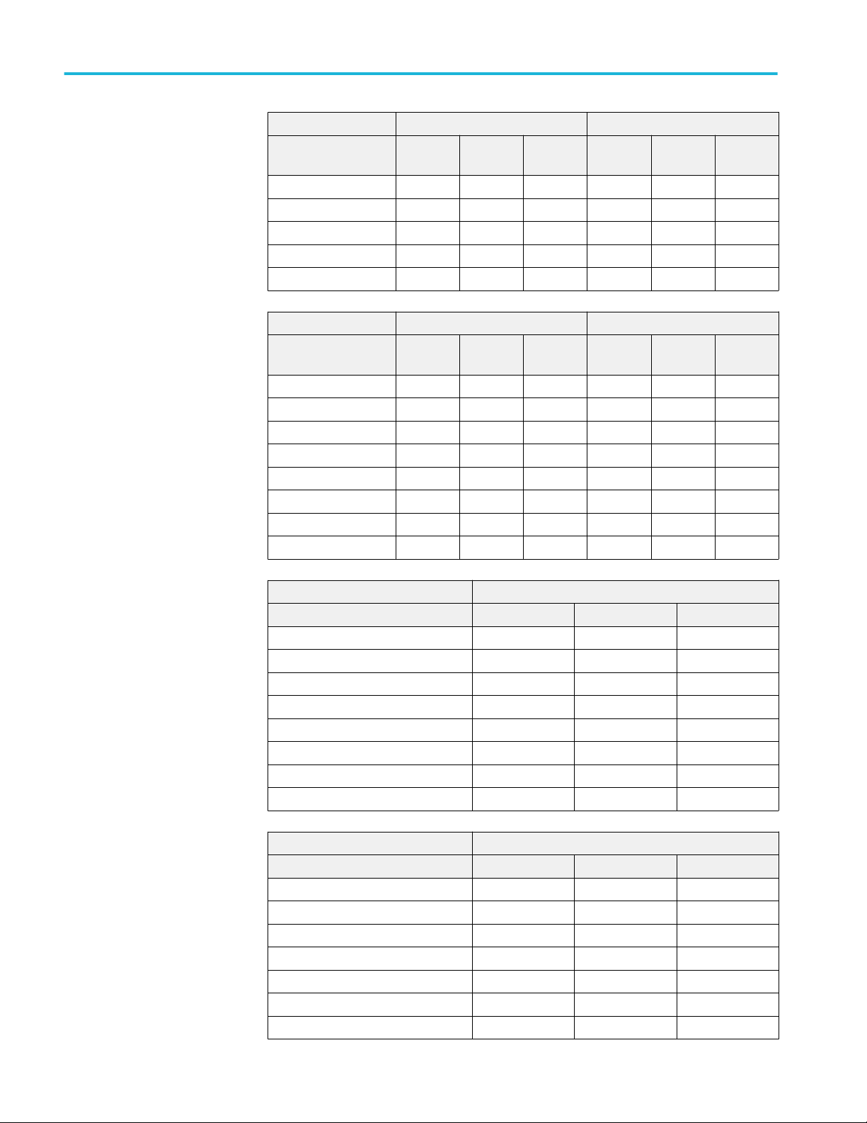
Specifications (MSO/DPO5000/B Series) Analog channel input and vertical specification (cont.)
MSO/DPO5204B 50 Ω termination 1 MΩ termination
Vertical Setting Full BW 250 MHzBW20 MHzBWFull BW 250 MHzBW20 MHz
BW
10 mV/div 0.65 0.37 0.33 0.85 0.45 0.45
20 mV/div 1.10 0.75 0.60 1.10 0.80 0.80
50 mV/div 2.50 1.90 1.50 2.30 2.00 1.90
100 mV/div 6.1 3.7 3.1 5.0 3.8 4.0
1 V/div 43.0 38.0 30.5 50.0 37.5 35.0
MSO/DPO5104B 50 Ω termination 1 MΩ termination
Vertical Setting Full BW 250 MHzBW20 MHzBWFull BW 250 MHzBW20 MHz
BW
1 mV/div 0.09 0.07 0.21 0.11
2 mV/div 0.17 0.12 0.10 0.38 0.20 0.13
5 mV/div 0.28 0.20 0.18 0.55 0.28 0.23
10 mV/div 0.45 0.37 0.33 0.65 0.45 0.40
20 mV/div 0.80 0.75 0.60 1.00 0.80 0.80
50 mV/div 2.00 1.90 1.50 2.30 2.00 1.90
100 mV/div 4.5 3.7 3.0 4.5 3.8 4.0
1 V/div 40.0 38.0 30.0 45.0 37.5 35.0
MSO/DPO5054B 50 Ω termination
Vertical Setting Full BW 250 MHz BW 20 MHz BW
1 mV/div 0.20 0.11
2 mV/div 0.27 0.21 0.13
5 mV/div 0.38 0.30 0.22
10 mV/div 0.55 0.55 0.45
20 mV/div 1.10 1.00 0.80
50 mV/div 2.50 2.50 1.90
100 mV/div 5.0 4.75 4.0
1 V/div 50.0 50.0 40.0
MSO/DPO5054B 50 Ω termination
Vertical Setting Full BW 250 MHz BW 20 MHz BW
1 mV/div 0.20 0.11
2 mV/div 0.27 0.21 0.13
5 mV/div 0.38 0.30 0.22
10 mV/div 0.55 0.55 0.45
20 mV/div 1.10 1.00 0.80
50 mV/div 2.50 2.50 1.90
100 mV/div 5.0 4.75 4.0
84 MSO70000C/DX, DPO70000C/DX, DPO7000C, MSO5000/B, DPO5000/B Series
Page 97

Analog channel input and vertical specification (cont.) Specifications (MSO/DPO5000/B Series)
MSO/DPO5054B 50 Ω termination
Vertical Setting Full BW 250 MHz BW 20 MHz BW
1 V/div 50.0 50.0 40.0
Delay between channels, full
bandwidth, typical
Deskew range –75 ns to +75 ns
Crosstalk channel isolation ≥100:1 at ≤100 MHz and ≥30:1 at >100 MHz up to the rated bandwidth for any two channels
TekVPI interface The probe interface allows installing, powering, compensating, and controlling a wide range of
Total probe power Five TekVPI-compliant probe interfaces (one per channel)
Probe power per channel
≤100 ps between any two channels with input impedance set to 50 Ω, DC coupling, with equal
volts/division setting or above 10 mV/div
All settings in the instrument can be manually time aligned using the Probe Deskew function
having equal Volts/Div settings
probes offering a variety of features.
The interface is available on all front panel inputs including Aux In. Aux In only provides 1 MΩ input
impedance and does not offer 50 Ω as the other input channels do.
15 W maximum internal probe power (12 W maximum with firmware versions <6.4.0)
Provision for 50 W probe power with 119-7465-00 TekVPI External Power Supply
Voltage Max Amperage Voltage Tolerance
5 V 50 mA (250 mW) ±5%
12 V 2 A (24 W) ±10%
MSO70000C/DX, DPO70000C/DX, DPO7000C, MSO5000/B, DPO5000/B Series 85
Page 98
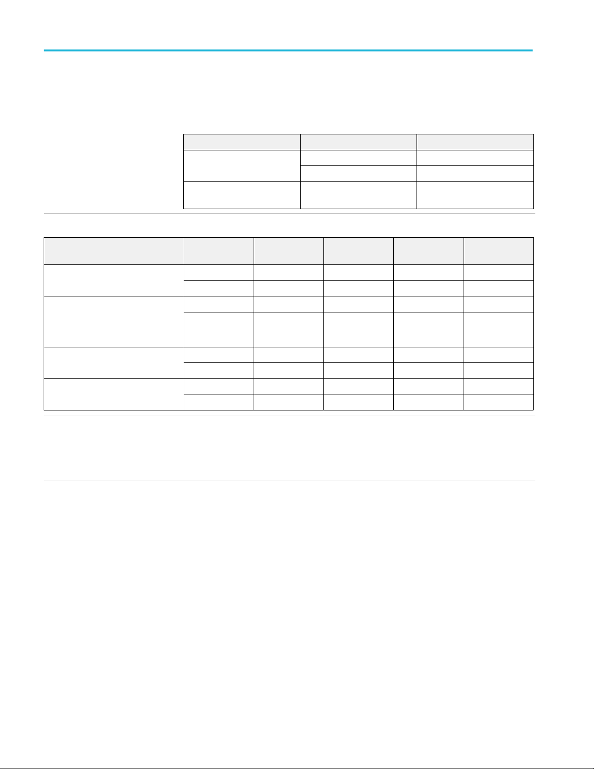
Specifications (MSO/DPO5000/B Series)
Horizontal and acquisition system specifications
Sample rate
Instrument Maximum sample rate Number of channels
MSO5204/B, DPO5204/B,
MSO5104/B, DPO5104/B
MSO5054/B, DPO5054/B,
MSO5034/B, DPO5034/B
Record length, analog channels
10 GS/s 1 or 2
5 GS/s 3 or 4
5 GS/s 1 – 4
Option Number of
Channels
Standard (MSO/DPO5000 Series) 3 or 4 12.5 M 12.5 M 12.5 M 12.5 M
1 or 2 25 M 25 M 12.5 M 12.5 M
Option 2RL
(MSO/DPO5000 Series)
Standard
(MSO/DPO5000B Series)
Option 5RL 3 or 4 50 M 50 M 50 M 50 M
Option 10RL 3 or 4 125 M 125 M 125 M 125 M
Record length, digital channels The record length ranges for a standard instrument are the same as for the analog channel
3 or 4 25 M 25 M 25 M 25 M
1 or 2 50 M 50 M 25 M 25 M
1 or 2 125 M 125 M 50 M 50 M
1 or 2 250 M 250 M 125 M 125 M
specification table (above).
The record length ranges for an instrument with an option are the same as for the analog channel
specifications, up to 40M.
2 GHz 1 GHz 500 MHz 350 MHz
86 MSO70000C/DX, DPO70000C/DX, DPO7000C, MSO5000/B, DPO5000/B Series
Page 99
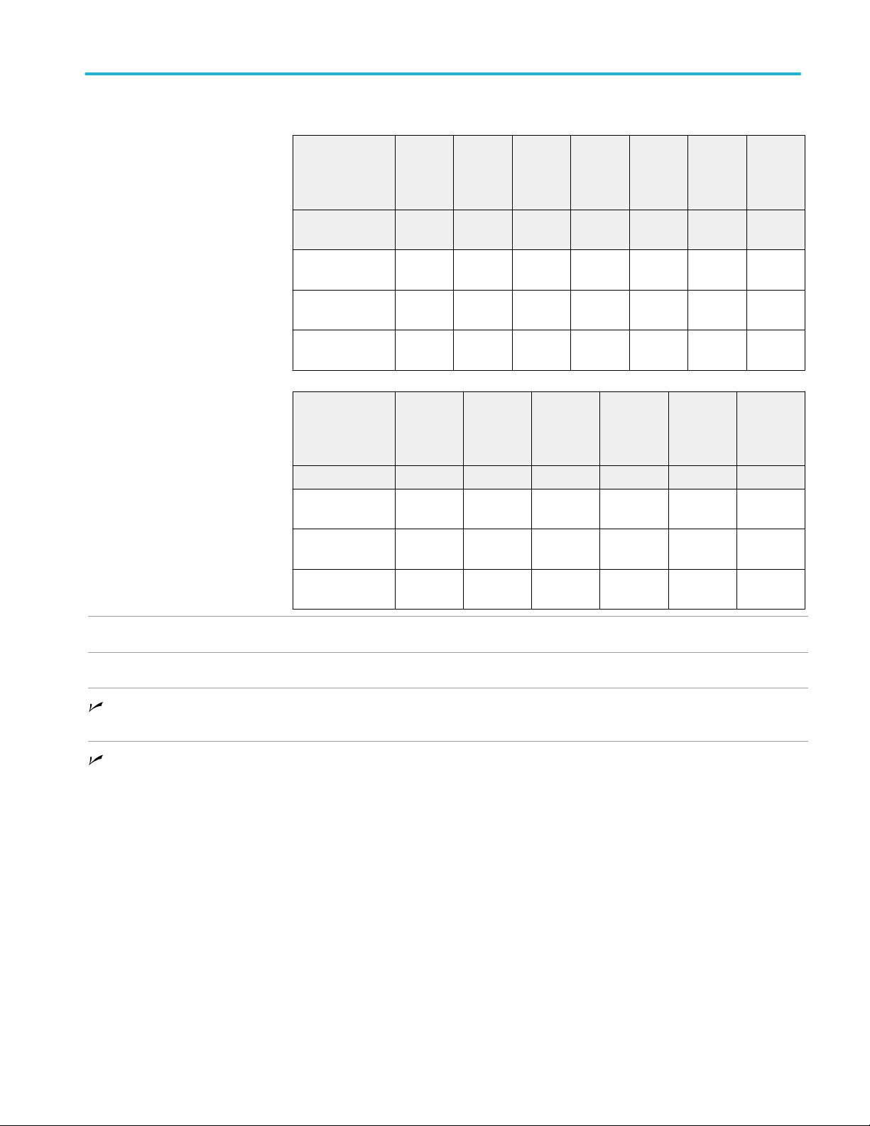
Horizontal and acquisition system specifications (cont.) Specifications (MSO/DPO5000/B Series)
Seconds/Division range
MSO5204B,
DPO5204B,
MSO5104B,
DPO5104B
Horizontal Mode 1 K 10 K 100 K 1 M 10 M 100 M 200/250
Automatic 250 ps -
Constant SR 250 ps -
Manual 250 ps -
MSO5054B,
DPO5054B,
MSO5034B,
DPO5034B
Horizontal Mode 1 K 10 K 100 K 1 M 10 M 100 M
Automatic 250 ps -
Constant SR 250 ps -
Manual 250 ps -
Record
Length
20 s
20 s
40 s
Record
Length
20 s
20 s
40 s
2.5 ns 200 s
2.5 ns 200 s
2.5 ns 400 s
2.5 ns 200 s
2.5 ns 200 s
2.5 ns 400 s
50 ns 1 ks
50 ns 1 ks
25 ns 4 ks
500 ns 1 ks
500 ns 1 ks
250 ns 40 ks
50 ns - 1 ks 500 ns -
50 ns - 1 ks 500 ns -
25 ns - 4 ks 250 ns -
5 us - 1 ks 50 us -
5 us - 1 ks 50 us -
2.5 us 400 ks
1 ks
1 ks
40 ks
M
50 us -
1 ks
1 ks
25 us 4 Ms
5 us - 1 ks 50 us - 1 ks
5 us - 1 ks 50 us - 1 ks
2.5 us 400 ks
1 ks
50 us 1 ks
50 us 8 Ms
25 us 4 Ms
Maximum update rate Maximum triggered acquisition rate: >250,000 wfm/s
Aperture uncertainty ≤(3 ps + 0.1 ppm × record duration)RMS, for records having ≤1 minute duration
Long-term sample rate and
delay time accuracy
Delta-time measurement
accuracy
±5 ppm over any ≥1 ms time interval
The formula to calculate the delta-time measurement accuracy (DTAmax) for a given instrument
setting and input signal is given below (assumes insignificant signal content above Nyquist and
insignificant error due to aliasing):
SR1 = slew rate around 1st point in measurement (1st edge)
SR2 = slew rate around 2nd point in measurement (2nd edge)
N =input-referred noise (VRMS)
TBA = time base accuracy (5 ppm)
tp = delta-time measurement duration (seconds)
RD = (record length)/(sample rate)
tsr = 1/(sample rate)
assume edge shape that results from Gaussian filter response
MSO70000C/DX, DPO70000C/DX, DPO7000C, MSO5000/B, DPO5000/B Series 87
Page 100

Specifications (MSO/DPO5000/B Series) Horizontal and acquisition system specifications (cont.)
N
2
N
DTA
DTA
pk-pk
RMS
= ±5 × 2
N
= 2
SR
+ 2
SR
1
2
N
+ 2
1
SR
2
2
+ (3ps + 1 × 10⁻⁷× RD)2+ 2tsrTBA × t
SR
2
2
+ (3ps + 1 × 10⁻⁷× RD)2+
(
2 × t
sr
12
2
)
+ TBA × t
p
p
The term under the square-root sign is the stability and is due to TIE (Time Interval Error). The
errors due to this term occur throughout a single-shot measurement. The second term is due to
both the absolute center-frequency accuracy and the center-frequency stability of the time base
and varies between multiple single-shot measurements over the observation interval (the amount of
time from the first single-shot measurement to the final single-shot measurement).
The observation interval may not exceed 1 year.
Trigger specifications
Aux in external trigger input
impedance, typical
Aux in (external) trigger maximum
input voltage
Aux in external trigger bandwidth,
typical
Trigger bandwidth, edge, typical
Trigger bandwidth, pulse and
logic, typical
1 M Ω ±1% in parallel with 13 pF ±2 pF
The maximum input voltage at the BNC 300 VRMS
Installation Category II
Derate at 20 dB/decade above 3 MHz to 30 VRMS at 30 MHz, 10 dB/decade above 30 MHz.
250 MHz ±20%
MSO5204/B, DPO5204/B 2 GHz
MSO5104/B, DPO5104/B 1 GHz
MSO5054/B, DPO5054/B 500 MHz
MSO5034/B, DPO5034/B 350 MHz 350 MHz
MSO5204/B, DPO5204/B 1 GHz
MSO5104/B, DPO5104/B 1 GHz
MSO5054/B, DPO5054/B 500 MHz
MSO5034/B, DPO5034/B 350 MHz
88 MSO70000C/DX, DPO70000C/DX, DPO7000C, MSO5000/B, DPO5000/B Series
 Loading...