

Page 1

Ethernet 10/100/1000BASE-T Application Software
TDSET3 • DPO4ENET Data Sheet
Applications
Features & Benefits
TDSET3 Ethernet Compliance Testing
Automated Compliance Testing for 10, 100, and 1000BASE-T PHY
Verification
Designed for use with MSO/DPO5000, DPO7000, and
DPO/DSA/MSO70000 Series Oscilloscopes
10BASE-T Eth
10BASE-Te Ethernet
100BASE-T Ethernet
1000BASE-T Ethernet
Tektronix offers comprehensive, integrated tool sets for validating the
physical layer of IEEE 802.3 Et hernet devices, and for developing a nd
debugging Ethernet-based systems.
The Tektronix TDSET3 Ethernet Compliance Test application and selected
Tektronix oscilloscopes provide one-button testing for 10/100/1000BASE-T
test suites as specified by the IEEE standard for compliance testing.
TDSET3 automates compliance testing and allows engineers to perform the
required te
The Tektronix DPO4ENET Serial Application Module and MSO/DPO4000B
Series osc
validating and debugging Etherne t-based systems. DPO4ENET offers
automated trigger, decode, and search for 10BASE-T and 100BASE-TX
Ethernet, enabling fast and efficient validation and debug.
ernet
sts efficiently and reliably right on the bench.
illoscopes sim plify analysis of Ethernet waveforms when
DPO4ENET Ethernet Triggering and Analysis
ted Trigger, Decode, and Search for 10BASE-T and
Automa
100BASE-TX Ethernet
Designed for use with the MSO/DPO4000B Series Oscilloscopes
Page 2
Data Sheet
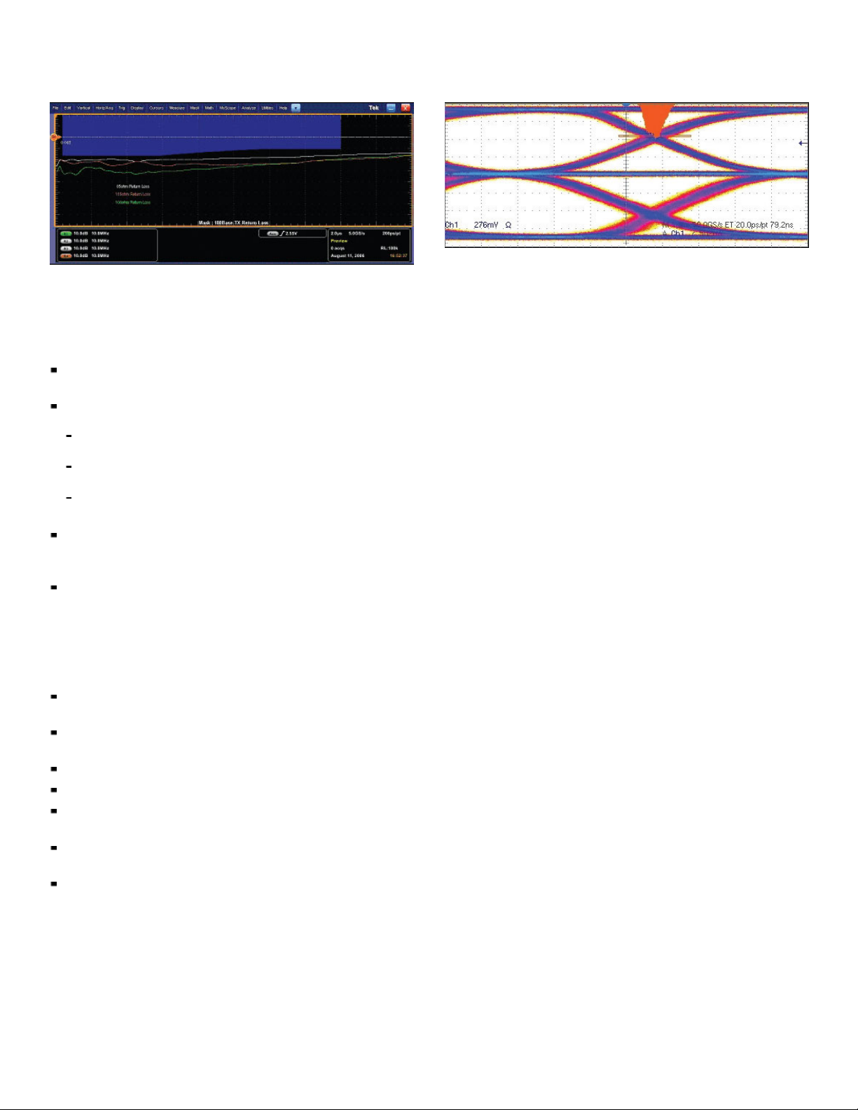
85/100/115 plots for the 100BASE-TX Return Loss measurement.
Peak-to-peak jitter on 100BASE-TX with single voltage crossing.
TDSET3 – Automated Ethernet Physical Layer
Compliance Testing
Ethernet compliance testing has some unique measurement challenges:
Generating the “disturbing ” signal requires tools to generate both pattern
data and noise to provide real-world noise for return loss measurements
There are many individual amp litude, timing, return loss, and template
tests requ
Because
takes a lot o f setup and measurement time, and makes repeatable
measurement results difficult to achieve quickly
Performing return loss measurements can be expensive if using a vector
networ
using an arbitrary waveform generator (AWG) and oscilloscope
The TDSET3 provides automated compliance testing for 10, 100, and
1000BASE-T PHY verification, including:
Compliance and margin testing for a ccu rate analysis and improved
interoperability
Time- and frequency-domain measurements made with single analysis
instrument
Jitter and timing measurements with and without filters
Amplitude, linearity, and droop testing for transmitter performance
Frequency domain measurements including return loss and power
spectral density
User-defined mode enables flexible parameter control for
characterization and margin analysis
Detailed test reports with margin and statistical information aid analysis
Wide Ra ng e of Tests
nsure reliable information transmission over a network, industry
To e
standards specify requirements for the network’s physical layer. The
ired for each Ethernet variant:
The 10BASE-T standard specifies 22 tests per port plus fault
tolerance and CMRR
The 100BA
more
The 1000BASE-T standard calls for 80 tests per port plus BER,
CMRR, and
SE-TX standard outlines 12 tests per port plus CMRR and
more
of the large number of individual tests, compliance testing
k analyzer. Tektronix provides a patented, cost-effective method
TDSET3 Ethernet Compliance Test Software a utomat es Ethernet physical
layer tests for 10BASE-T, 10BASE-Te, 100BASE-TX, and 1000BASE-T
in compliance with standards such as IEEE 802.3-2000 and ANSI
X3.263-1995. The portfolio of tests includes core PMA and MDI tests like
Template, Distortion, Return Loss, Jitter (including the proposed alternate
jitter method), and Common Mode Voltage.
Amplitude Domain Tests
The industry standards require th e signals to have amplitudes within
specified ranges to assure interoperabili
tests vary with the signal speeds, but include such parameters as peak
or p eak-to-peak amplitude, overshoot, common mode voltage, and
positive/negative pulse symmetry.
ty between devices. The amplitude
Return Loss Test
The return loss of the cabling system can also affect interoperability.
The standards define the minimum amount of attenuation the reflected
signal should have relative to the incident signal. The Return Loss test
measures the impedance, typically over the range of 100 ±15%. TDSET3
ingeniously performs the Return Loss test for 85, 100, and 115 (111 for
10BASE-T) impedances as prescribed by the standards, using the same
tools such as oscilloscopes and AWG used for other tests, enabling efficient
usage of resources.
Time Domain Tests
Timing parameters of the signals are also specified by the standards.
These tests include timing measurements such as rise time, fall time, and
difference or symmetry between rise and fall times.
Jitter Tests
Jitter tests quantify the timing variations of the edges of the signal, using
specified test patterns. These jitter measurements include the contributions
from duty cycle distortion and the baseline wander. Jitter is determined by
accumulating waveforms, measuring the widt h of the accumulated points
at the eye crossing, and the peak-to-peak is inferred from minimum and
ximum values in the tails of the histogram. For example, the figure above
ma
shows the jitter measurement on a 100BASE-TX signal.
2 www.tektronix.com
Page 3

Ethernet 10/100/1000BASE-T Application Software — TDSET3 • DPO4ENET
Positive side AOI Template test of 100BASE-TX signal.
Template Tes ts
Template mask tests are often used to quickly verify that the transmitted
signal meets industry-standard requirements. These template masks
are defined so that signal distortions such as overshoot, jitter, incorrect
rise and fall times, etc., will cause the mask test to fail. An example of a
100BASE-TX template mask test is shown above.
TF-GBE-BTP Basic Ethernet Test Fixture.
Test Report Generation
The unparalleled au tomation built into TDSET3 also enables faster
validation including the tedious task of generating reports. The user can
generate summary or detailed reports at a press of a button.
Test Fixtures
The TF-GBE Series of test fixtures supports many of th e Ethernet
compliance tests, providing convenient signal access, test points for
accurate removal of disturbing signals, return loss calibration, and
cross-connect circuits to connect to traffic generators and link partners.
GBE-BTP is the basic test package for 10/100/1000BASE-T tests.
The TFThe TF-GBE-ATP is the advanced test package which also includes a
1000BASE-T jitter test channel cable.
EE Test Fixture for Energy Efficient Ethernet measurements on 10BASE-Te.
TF-GBE-
The TF-GBE-EE is an additional test fixture which is required to perform the
Energy Efficient Ethern et measurements.
Complete Solution for Receiver Test
Tektronix offers a complete solution for creating and managing “disturbing”
signals for accurate receiver stress testing. The Tektronix arbitrary
waveform generators provide support for a dding and removing the
noise-related elements of the disturbing signal. Tektronix offers a complete
nstruments for Ethernet compliance tests and debug work; from
setofi
oscilloscopes and probes, to compliance test software, test fixtures, and
signal sources.
www.tektronix.com 3
Page 4

Data Sheet
g on a specific 10BASE-T MAC source address. A complete set of triggers,
Triggerin
triggers for specific MAC address, MAC length/type, MAC client data, IPv4 and
including
TCP header
capture yo
content, TCP and IPv4 client data, and FCS errors, ensures you quickly
ur event of interest.
DPO4ENET – 10BASE-T and 100BASE-TX
Triggering and Analysis
Debugging Ethernet-based embedded system s designs provide s some
complex measurement and analysis cha llenges:
Capturing specific Ethernet addresses an d data
Displaying the eleme nts of the Ethernet message in an understandable
in a variety of formats, for a wide variety of engineers and
format,
technicians
Time-correlating Ethernet messages with analog and digital signals in
the embedded system
Capturing long time windows of Ethernet traffic and then finding specific
within the acquired data
events
The DPO4ENET application module, installed in an MSO/DPO4000B
Series oscilloscope, provides a robust set of tools for debugging embedded
s with 10BASE-T and 100BASE-TX Ethernet, including:
system
ated serial triggering, decode, and search for Ethernet 10BASE-T
Autom
and 100BASE-TX
Triggering on all the critical elements of an Ethernet 10BASE-T and
100BASE-TX such as address, data, etc.
Triggering on and decoding IPv4 internet protoc ol and TCP transport
col
proto
ding all the critical elements of each message. No more counting
Deco
1s and 0s!
Searching through long acquisitions using user-definedcriteriatofind
specific messages
Event Table showing decoded serial bus activity in a tabular,
e-stamped format for quick summary of system activity
tim
ed display of 100BASE-TX, showing preamble, MAC addresses, IP header, TCP
Color-cod
header com
ponents of the serial signal.
10BASE-T and 100BASE-TX Triggering
Trigger on packet content such as start frame delimiter (SFD), MAC
addresses, MAC length/type, MAC client data, Q-tag control information,
IPv4 and TCP header, TCP and IPv4 client data, end-of-packet, and FCS
errors.
10BASE-T and 100BASE-TX Decode
The DPO4ENET Ethernet Serial Application Module provides a higher-level,
combined view of the individual signals that make up the 10BASE-T or
100BASE-TX bus, making it easy to identify where packets begin and
end and identifying subpacket components such as preamble, SFD, MAC
addresses, data, FSC, errors, etc.
Are you wasting time manually decoding the waveform? Tired of having
to visually inspect the waveform to count clocks, determine if each bit is
a1ora0
, combine bits into byte s, and determine the hex value? Let the
MSO4000B or DPO4000B with a DPO4ENET Ethernet Serial Application
Module do it for you! Once you’ve set up a 10BASE-T o r 100BASE-TX bus,
the MSO4000B or DPO4000B Series will decode each packet on the bus,
and display the value in hex, binary, or ASCII in the bus waveform.
4 www.tektronix.com
Page 5

Ethernet 10/100/1000BASE-T Application Software — TDSET3 • DPO4ENET
100BASE-T
informati
10BASE-T and 100BASE-TX Event Table
In addition to seeing 10BASE-T and 100BASE-TX decoded data on the
bus waveform itself, you can view all captured packets in a tabular view
much like you would see in a software listing. Packets are time stamped and
listed consecutively with columns for each component (Time, Destination
Address, Source Address, Length, Data, FCS/CRC, and Errors).
10BASE-T and 100BASE-TX Search
10BASE-T and 100BASE-TX packet content triggering is very useful for
isolating the event of interest, but once you’ve captured it and need to
analyze the surrounding d ata, what do you do? In the past, users had
to manually scroll through the waveform counting and converting bits
and loo
Serial Application Module, you can enable the MSO4000B or DPO4000B
Series oscilloscope to automatically search through the acquired data
for user-defined criteria including packet content. Each occurrence is
highlighted by a search mark. Rapid navigation between marks is as simple
as pressing the Previous ()andNext () buttons on the oscilloscope
front p
X decoded Event Table showing all packet information with time stamp
on.
king for what caused the event. With a DPO4ENET Ethernet
anel.
Characteristics
TDSET3 Compliance Test Characteristics
General Mask
Autofit, Waveform/Sample Count.
Instrument Compatibility
Model Description
MSO5034
DPO5034
MSO5054
DPO5054
MSO5104
DPO5104
MSO5204
DPO5204
DPO7054
DPO7104
DPO7254
DPO7354
DPO/DSA/MSO70K
Series
10BASE-T/10BASE-Te
Test Description
Template
MAU Template
Scale
Amplitude
Harmonic
Jitter With and without cable
Return Loss
ASE-TX
100B
Test Description
Template Positive and negative polarity
Amplitude
Time Domain Tests
Jitter Jitter and duty cycle distortion
Return Loss
1000BASE-T
Test Description
Template
Amplitude
Disturber Options
Jitter
Return Loss
*185 and 115 plots require four-channel oscilloscopes.
2
If clock inaccuracy is high, results may vary on some oscilloscopes due to limitations on the segmented
*
memory acquisitions.
3
*
Slave-filtered tests require four-channel oscilloscopes.
Recommended for Compliance Testing of 10BASE-T and
10BASE-Te
Recommended for Compliance Testing of 10BASE-T,
10BASE-Te, and 100BASE-TX
Recommended for Compliance Testing of 10BASE-T,
10BASE-Te, 100BASE-TX, and 1000BASE-T
MAU Ext (and inverted), MAU Int (and inverted), Link Pulse,
and TP_IDL
0.9 and 1.1
Differential voltage, common mode output voltage
Content of ones
85, 100, 111 *
1
Signal amplitude, amplitude symmetry, differential output
voltage, waveform overshoot
Rise Time, Fall Time, Rise/Fall Time Symmetry
85, 100, 111 *
1
Points A, B, C, D, F, H
Peak voltage (points A, B)
Level Accuracy (points B, C, D)
Droop (points G, J)
Distortion (with and without TX_TCLK*
2
)
Common Mode Output Voltage
With and without disturber signal
3
Master (filtered and unfiltered), Slave*
(filtered and
unfiltered)
85, 100, 111 *
1
www.tektronix.com 5
Page 6

Data Sheet
DPO4ENET Ethernet Triggering and Analysis Test
Characteristi
cs
Instrument Compatibility
Model Description
MSO4034B
MSO4054B
MSO4104B
DPO4034B
DPO4054B
DPO4104B
Trigger and Decode: 10BASE-T and 100BASE-TX
Bus Setup Options
Option
Ethernet
Compatibility
Sources Single-ended:
Recommended
Probing
Thresholds Presets
Address/Data
Formats Available
Description
10BASE-T, 100BASE-TX
Analog channels 1-4
Differential:
Analog channels 1-4
Math channel
Reference channels 1-4
10BASE-T: Single-ended or differential
100BASE-TX: Differential
10BASE-T: Single-ended (D+ 1.25 V; D– 1.25 V); Differential
(High 1.25 V; Low –1.25 V)
100BASE-TX: Single-ended (D+ 500 mV; D– 500 mV);
Differential (High 500 mV; Low –500 mV)
Hex
Binary
Hex or ASCII: Data
Decimal and Hex: Other Fields
Bus Decode
Characteristic
Ethernet Data
Rates
Decode Display
Internet Protocol
Support
Transport Layer
Protcol Support
Description
10BASE-T: 10 Mb/s
100BASE-TX: 100 Mb/s
Start (green bar)
MAC Address (yellow packet)
Data (cyan packet)
IPv4 Header (white packet)
TCP Header (brown packet)
CRC (purple packet)
Stop (red bar)
Error (red packet)
IPv4
TCP
Display Modes
Mode Description
Bus Bus only
Bus and Waveforms Simultaneous display of bus and digital waveforms
Event Table Decoded packet data in a tabular view
Bus Trigger Options
ription
Option
Trigger and/or Search On 10BASE-T:
Desc
Start Frame Delimiter
MAC Addresses: Trigger on source and destination 48-bit addresses
MAC Length/Type: Trigger on ,<,=,>,, a particular 16-bit value, or inside or outside of a range
MAC Client Data: Trigger on ,<,=,>,, a particular 16-bit value, or inside or outside of a range. Selectable number of bytes to
trigger on from 1-16. Byte offset options of Don't Care, 0-1499
MAC Q-tag Control Information: Trigger on Q-tag 32-bit value
IP Header: Trigger on IP header 4-bit value, Source Address, Destination Address.
TCP Header: Trigger on Destination Port, Source Port, Sequence Number, and Ack Number
TCP/IPv4 Client Data: Trigger on ,<,=,>,, a particular data value, or inside or outside of a range
End of Packet
FCS (CRC) Error
100BASE-TX:
Start Frame Delimiter
MAC Addresses: Trigger on Source and Destination 48-bit address values
MAC Q-tag Control Information: Trigger on Q-tag 32-bit value
MAC Length/Type: Trigger on ,<,=,>,, a particular 16-bit value, or inside or outside of a range
IP Header: Trigger on IP header 4-bit value, Source Address, Destination Address
TCP Header: Trigger on Destination Port, Source Port, Sequence Number, and Ack Number
TCP/IPv4 Client Data: Trigger on ,<,=,>,, a particular data value, or inside or outside of a range. Selectable number of bytes to
trigger on from 1-16. Byte offset options of Don't Care, 0-1499
MAC Client Data: Trigger on ,<,=,>,, a particular data value, or inside or outside of a range. Selectable number of bytes to
trigger on from 1-16. Byte offset options of Don't Care, 0-1499
End of Packet
Idle
FCS (CRC) Error
6 www.tektronix.com
Page 7

Ordering Information
Ethernet 10/100/1000BASE-T Application Software — TDSET3 • DPO4ENET
TDSET3 10, 100, 1000BASE -T Ethernet Physical-layer
Compliance Test Application
Model New Instrument
Orders
MSO/DPO5000 Series Opt. ET3 DPO-UP
Product
Upgrades
Floating
Licenses
DPOFL-ET3
Opt. ET3
DPO7000 Ser
ies
Opt. ET3 DPO-UP
DPOFL-ET3
Opt. ET3
DPO/DSA/MSO70000
Series
Opt. ET3 DPO-UP
Opt. ET3
DPOFL-ET3
TDSET3 Recommended Accessories
For most Ethernet signal probing, use a 1-1.5 GHz differential probe.
For 1000BASE-T jitter testing, use two 1-1.5 GHz active probes for slave jitter test,
and one 1-1.5 GHz active probe for master jitter test.
Please refer to www.tek.com/probes for further information on the recommended
models of probes and any necessary probe adapters.
Ethernet Test Fixtures
Fixture Description
E-BTP
TF-GB
E-ATP
TF-GB
E-EE
TF-GB
E-JTC
TF-GB
BE-SIC
TF-G
*4Order directly from Crescent Heart Software http://www.c-h-s.com/.
Basic Ethernet Test Package
ced Ethernet Test Package, includes Jitter Channel
Advan
yEfficient Ethernet Test Package*
Energ
eter 1000BASE-T Jitter Test Channel Cable
103-m
t (4 inch or 0.1 meter) RJ-45 Interconnect Cable
Shor
4
DPO4ENET MSO/DPO4000B Series 10BASE-T and
100BASE-TX Triggering and Analysis Application
Model New Instrument
Orders
MSO/DPO4000 Series DPO4ENET DPO4ENET
Product
Upgrades
Floating
Licenses
—
Recommended Probes
Please refer to www.tek.com/probes for further information on the recommended
models of probes and any necessary probe adapters.
Additional
Tektroni x
and 40/100
resources
TDSET3 sol
at: www.te
Information
offers a range of solutions for Ethernet testing, including 10GBASE-T
G Ethernet. To see a comprehensive listing, and download the latest
, visit: www.tek.com/ethernet.
ution updates and up-to-date instrument software upgrades are available
k.com/downloads.
Product(s) are m
anufactured in ISO registered facilities.
Signal Source (for Return Loss and Disturbing Signal Tests)
5
102*
AFG3
Gene
*5Setup filesandwaveformstobecopiedontotheinstrumentusingamemorystick.
6
Two am pl ifiers, one for each channel, are required. Tektronix has qualified Picosecond Pulse Labs Amplifier
*
Model #5866.
, AFG3252*5, AWG5000C, or AWG7000C*6Series Arbitrary Waveform
rator.
www.tektronix.com 7
Page 8

Data Sheet
Contact Tektronix:
ASEAN / Australa
Balkans, Israel, South Africa and other ISE Countries +41 52 675 3777
Central East Eu
Mexico, Central/South America & Caribbean (52) 56 04 50 90
* European toll-free number. If not accessible, call: +41 52 675 3777
rope, Ukraine, and the Baltics +41 52 675 3777
Central Europe & Greece +41 52 675 3777
Middle East,
Asia, and North Africa +41 52 675 3777
The Netherlands 00800 2255 4835*
People’s Rep
Republic of
United Kingdom & Ireland 00800 2255 4835*
sia (65) 6356 3900
Austria 00800 2255 4835*
Belgium 00800 22
Brazil +55(11)37597600
Canada 1 800 833 9200
Denmark +4580881401
Finland +41526
France 008 00 2255 4835*
Germany 00800 2255 4835*
Hong Kong 400 8
India 000 800 650 1835
Italy 00800 2255 4835*
Japan 81 (3) 67
Luxembourg +41526753777
ublic of China 400 820 5835
Poland +41 52 675 3777
Korea 001 800 8255 2835
Russia & CIS +7 (495) 7484900
South Africa +41526753777
Spain 00800
Sweden 00800 2 255 4835*
Switzerland 00800 2255 4835*
Tai wa n 886 (
55 4835*
75 3777
20 5835
14 3010
Norway 800 16098
Portugal 80 08 12370
2255 4835*
2) 2722 9622
USA 1 800 833 9200
Updated 25 May 2010
www.tektronix.com
For Further I nformation. Tektronix maintains a comprehensive, constantly expanding
collection of application notes, t echnical briefs and other resources to help engineers working
on the cutting edge of technology. Please visit www.tektronix.com
t © Tektronix, Inc. All rights r eserved. Tektronix products are covered by U.S. and foreign patents,
Copyrigh
d pending. Information in this publication supersedes that in all previously published material.
issued an
tion and price change privileges reserved. TEKTRONIX and TEK are registered trademarks of
Specifica
x, Inc. All other trade names referenced are the service marks, trademarks, or registered trademarks
Tek tro ni
espective companies.
of their r
06 Jan 2011 61W-26144-1
 Loading...