

Mixed Signal Oscilloscopes
MSO4000B, DPO4000B Series Data Sheet
Connectivity
Two USB 2.0 Host Ports on the Front Panel and Two on the Rear Panel
for Quick and Easy Data Storage, Printing, and Connecting a USB
Keyboard
USB 2.0 Device Port on Rear Panel for Easy Connection to a PC or
Direct Printing to a PictBridge
Integrated 10/100/1000BASE-T Ethernet Port for Network Connection
and Video Out Port to Export the Oscilloscope Display to a Monitor or
Projector
Optional Serial Triggering and Analysis
Automated Serial Triggering, Decode, and Search Options for I2C,
SPI, USB, Ethernet, CAN, LIN, FlexRay, RS-232/422/485 /UART,
MIL-STD-1553, and I
Mixed Signal Design and Analysis (MSO Series)
Features & Benefits
Key Performance Specifications
1 GHz, 5 00 MHz, 350 MHz Bandwidth Models
4 Analog Channel Models
16 Digital Channels (MSO Series)
Up to 5 GS/s Sample Rate on All Channels
20 Megapoint Record Length on All Channels
>50,000 wfm/s Maximum Waveform Capture Rate
Standard Passive Voltage Probes with Less than 4 pF Capacitive
Loading and 500 MHz or 1 GHz Analog Bandwidth
Suite of Advanced Triggers
Ease of Use Features
Wave Inspector®Controls provide Easy Navigation and Automated
Search of Waveform Data
41 Automated Measurements, Waveform Histograms, and FFT Analysis
for Simplified Waveform Analysis
TekV P I®Probe Interface supports Active, Differential, and Current
Probes for Automatic Scaling and Units
10.4 in. (264 mm) Bright XGA Color Display
Small Footprint and Lightweight – Only 5.8 in. (147 mm) d eep and 11 lb.
(5 kg)
Automated Triggering, Decode, and Search on Parallel Buses
Per-channel Threshold Settings
Multichannel Setup and Hold Triggering
MagniVu™ High-speed Acquisition Pro vides 60.6 ps Fine Timing
Resolution on Digital Channels
Optional Application Support
Power Analysis
Limit and Mask Testing
HDTV and Custom Video Analysis
Feature-rich Tools for Debugging Mixed
Signal Designs
With the MSO/DPO4000B Mixed Signal Oscilloscope Series, you can
analyze up to 20 analog and digital signals with a single instrument to
quickly find and diagnose problems in complex designs. Bandwidths up to
1 GHz and a minimum of 5X oversampling on all channels ensure you have
the performance you need to se e fast-changing signal details. To capture
long windows of signal activity while maintaining fine timing resolution, the
MSO/DPO4000B Series offers a deep record length of 20M points standard
on all channels.
With Wave Inspector
serial and parallel bus analysis, limit and mask testing, and automated
power analysis – the MSO/DPO4000B Oscilloscope Series from Tektronix
provides the feature-rich tools you need to simplify and speed debug of
your complex design.
®
-compatible Printer
2
S/LJ/RJ/TDM
®
controls for rapid waveform navigation, autom ated
Data Sheet
Discover –
of capturi
Fast waveform capture rate - over 50,000 wfm/s - maximizes the probability
ng elusive glitches and other infrequent events.
Comprehensive Features Speed Eve ry Stage
of Debug
The MSO/DPO4000B Series offers a robust set of features to speed every
stage of debugging your design – from quickly d iscovering an anomaly and
capturing it, to searching your waveform record for the event and analyzing
its characteristics and your device’s behavior.
Discover
To debug a design problem, first you must know it exists. Every
design engineer spends time looking for problems in their design, a
time-consuming and frustrating task without the right debug tools.
The M SO/DPO40 00B Series offers the industry’s most comp lete
visualization of signals, providing fast insight into the real operation of your
device. A fast waveform capture rate - greater than 50,000 waveforms
per second - enables you to see glitches and other infrequent transients
seconds, revealing the true nature of device faults. A digital phosphor
within
display with intensity grading shows the history of a signal’s activity by
intensifying areas of the signal that occur more frequently, providing a visual
display of just how often anomalies occur.
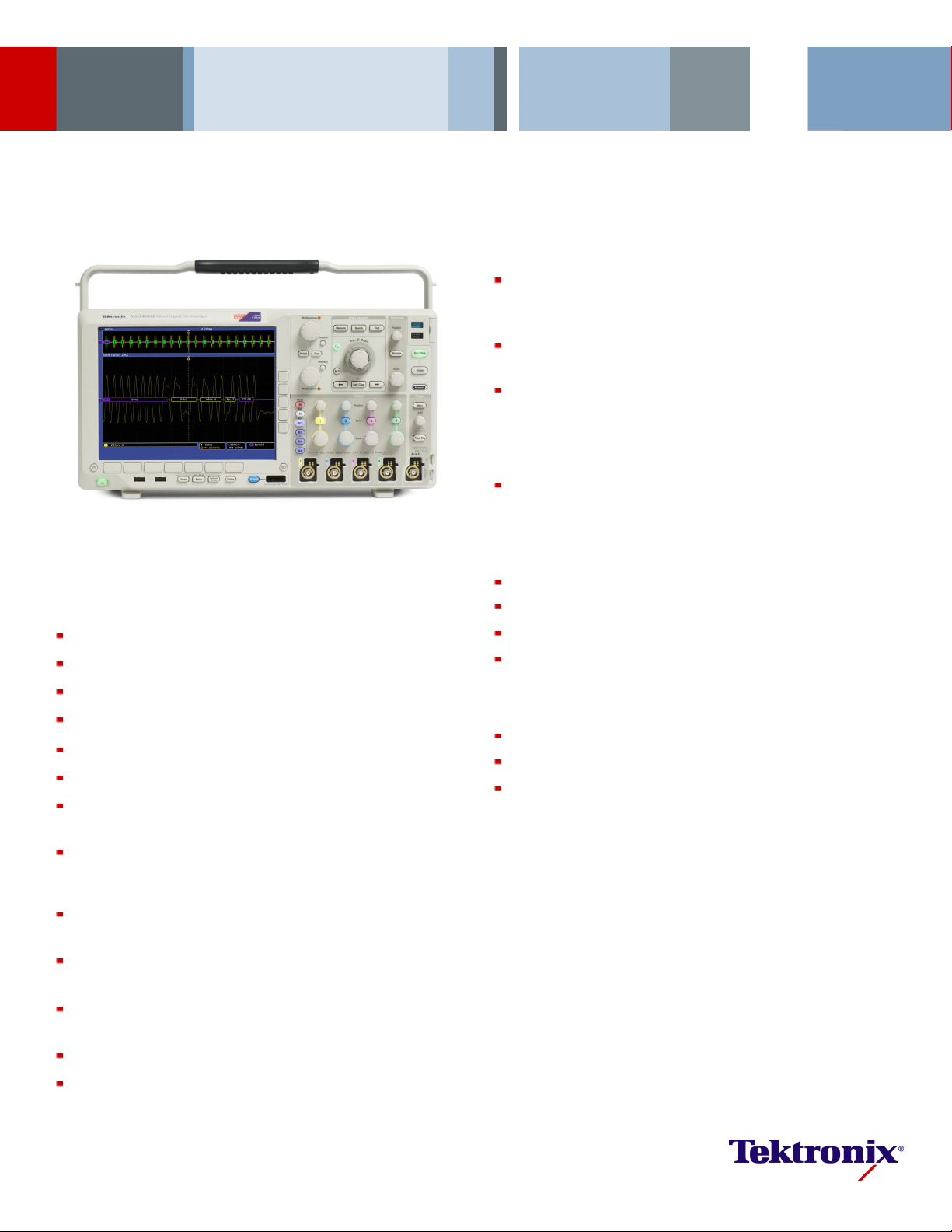
Capture – T
complete s
quickly ca
riggering on a specific transmit data packet going across an RS-232 bus. A
et of triggers, including triggers for specific serial packet content, ensures you
pture your event of interest.
Capture
Discovering a device fault is only the first step. Next, you must capture the
event of interest to identify root cause.
Accurately capturing any signal of interest b egins with proper probing. The
MSO/DPO4000B Series includes four low-capacitance probes for accurate
signal capture. These industry-first high-impedance passive voltage probes
have less than 4 pF of capacitive loading to minimize the affect of the probe
on your circuit’s operation, offering the performance of an active probe with
the flexib
ility of a passive probe.
The MSO/DPO4000B Series provides a complete set of triggers – including
meout, logic, pulse width/glitch, setup/hold violation, serial packet,
runt, ti
and parallel data – to help quickly find your event. With up to a 20M point
record length, you can capture many events of interest, even thousands of
serial packets, in a single acquisition for further analysis while maintaining
high resolution to zoom in on fine signal details.
From triggering on specific p acket content to au tomatic decode in
multiple data formats, the MSO/DPO4000B Series provides integrated
support for the industry’s broadest range of serial buses – I
t, CAN, LIN, FlexRay, RS-232/422/485/UART, M IL-STD-155 3, and
Etherne
2
I
S/LJ/RJ/TDM. The ability to decode up to four serial and/or parallel buses
2
C, SPI, U SB,
simultaneously means you gain insight into system-level problems quickly.
To further help troubleshoot system-level interactions in complex embedded
systems, the MSO4000B Series offers 16 digital channels in addition to
its analog channels. Since the digital channels are fully integrated into
the oscilloscope, you can trigger across all input channels, automatically
time correlating all analog, digital, and serial signals. The MagniVu™
peed acquisition enables you to acquire fine signal detail (up to
high-s
60.6 ps resolution) around the trigger point for precision measurements.
MagniVu is essential for making accurate timing measurements for setup
and hold, clock delay, signal skew, and glitch characterization.
2 www.tektronix.com
Mixed Signal Oscilloscopes — MSO4000B, DPO4000B Series
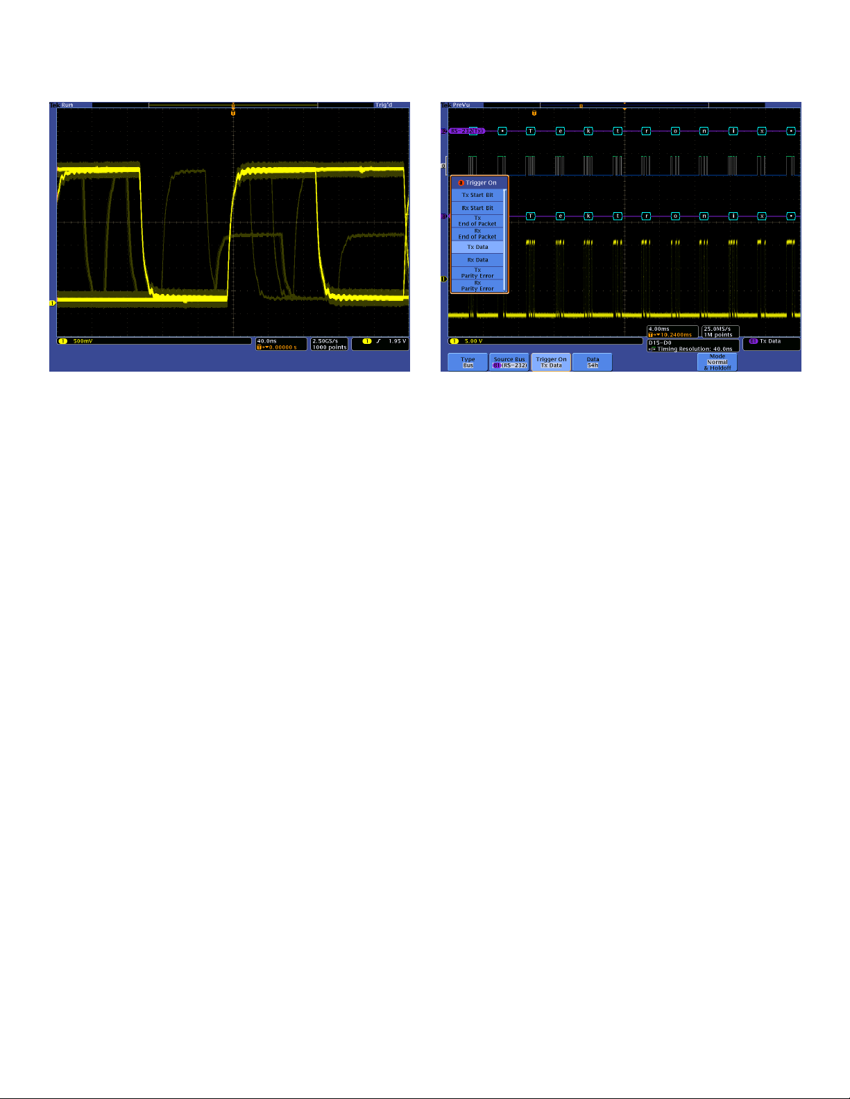
Search–I2C decode showing results from a Wave Inspector search for Address value
50. Wave Inspector controls provide unprecedented efficiency in viewing and navigating
waveform data.
Search
Finding your event of interest in a long waveform record can be time
consuming without the right search tools. With today’s record lengths
pushing beyond a million data points, locating your event can mean scrolling
through thousands of screens of signal activity.
The MSO/DPO4000B Series offers the industry’s most comprehe nsive
search and waveform navigation with its innovative Wave Inspector
®
controls. These controls speed panning and zooming through your record.
With a unique force-feedback system, you can move from one end of your
record to the other in just seconds. User marks allow you to mark any
n that you may want to reference later for further investigation. Or,
locatio
automatically search your record for criteria you de fine. Wave Inspector
will instantly search your entire record, including analog, digital, and serial
bus data. Along the way it will automatically mark every occurrence of your
defined event so you can quickly move between events.
Analyze – W
(jitter) o
data. A com
performan
aveform histogram of a falling edge showing the distribution of edge position
ver time. Included are numeric measurements made on the waveform histogram
prehensive set of integrated analysis tools speeds verification of your design’s
ce.
Analyze
Verifying that your prototype’s performance matches simulations and meets
the project’s design goals requires analyzing its behavior. Tasks can range
from simple checks of rise times and pulse widths to sophisticated power
loss analysis and investigation of noise sources.
The MSO/DPO4000B Series offers a comprehensive set of integrated
analysis tools including waveform- and screen-based cursors, 41
automated measurements, advanced waveform math including arbitrary
n editing, waveform histograms, FFT analysis, and trend plots for
equatio
visually determining how a measurement is changing over time. Specialized
application support for serial bus analysis, power supply d esign, limit and
mask testing, and video design and development is also available.
For extended analysis, National Instrument’s LabVIEW SignalExpress™
Tektronix Edition provides over 200 built-in functions including time and
frequency domain analysis, data logging, and customizable reports.
www.tektronix.com 3
Data Sheet
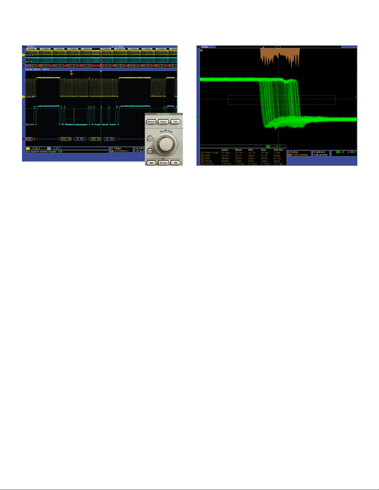
Search step 1: You define what you would like to find.
Wave Inspector controls provide unprecedented efficiency in viewing, navigating, and
analyzing waveform data. Zip through your 20M point record by turning the outer pan
control (1). Get from the beginning to end in seconds. See something of interest and want
to see more details? Just turn the inner zoom control (2).
Wave Inspector®Navigation and Search
A 20M point record length represents thousands of screens of information.
The MSO/DPO4000B Series enables you to find your event in seconds with
Wave Inspector, the industry’s best tool for navigation and search.
Wave Inspector offers the following innovative controls:
Zoom/Pan
A dedicated, two-tier front-panel control provides intuitive control of both
zooming and panning. The inner control adjusts the zoom factor (or zoom
scale); turning it clockwise activat es zoom and goes to progressively higher
ctors, while turning it counte rclockwise results in lower zoom factors
zoom fa
and eventually turning zoom off. No longer do you need to navigate through
multiple menus to adjust your zoom view. The outer control pans the zoom
box across the waveform to quickly get to the portion of waveform you are
interested in. The outer control also utilizes force feedback to determine
how fast to pan on the waveform. The farther you turn the outer control, the
the zoom box moves. Pan direction is changed by simply turning the
faster
control the other way.
Play/Pause
cated Play/Pause front-panel button scrolls the waveform across the
A dedi
display automatically while you look for anomalies or an event of interest.
Playback speed and direction are controlled using the intuitive pan control.
Once again, turning the control further makes the waveform scroll faster an d
changing direction is a s simple as turning the c ontrol the other way.
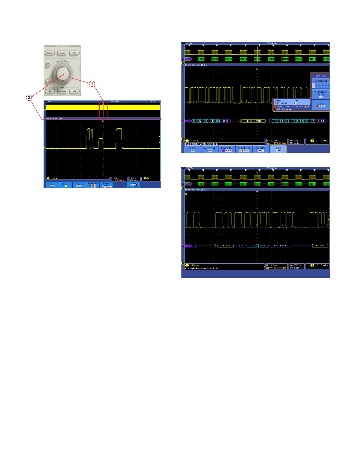
Search step 2: Wave Inspector automatically searches through the record and marks each
event with a hollow white triangle. You can then use the Previous and Next buttons to
jump from one event to the next.
User Marks
Press the Set Mark front-panel button to place one or more marks on
the waveform. Navigating between marks is as s imple as pressing the
Previous (←)andNext (→) buttons on the fro nt panel.
Search Marks
The Search button allows you to automatically search through your long
acquisition looking for user-defined events. All occurrences of the event
ghlighted with search marks and are easily navigated to, using the
are hi
front-panel Previous (←) and Next (→) buttons. Search types include
edge, pulse width/glitch, timeout, runt, logic, setup and hold, rise/fall
time, parallel bus, and I
RS-232/422/485/UART, MIL-STD-1553, and I
2
C, SPI, USB, Ethernet, CAN, LIN, FlexRay,
2
S/LJ/RJ/TDM packet content.
4 www.tektronix.com
osphor technology enables greater than 50,000 wfm/s waveform capture rate
Digital ph
ime intensity grading on the MSO/DPO4000B Series.
and real-t
Digital Phosphor Te chnology
The MSO/DPO4000B Series’ digital phosphor technology provides you with
fast insight into the real operation of your device. Its fast waveform capture
rate - greater than 50,000 wfm/s - g ives you a high probability of quickly
seeing the infrequent problems common in digital systems: runt pulses,
glitches, timing issues, and more.
Waveforms are superimposed with one another an d waveform points that
occur more frequently are intensified. This quickly highlights the events
that over
occur less often.
With the M
variable persistence (including zero persistence), determining how long
the previous waveform acquisitions stay on-screen. This allows you to
determine how ofte n an anomaly is occurring.
time occur more often or, in the case of infrequent anomalies,
SO/DPO4000B Series, you can choose in finite persistence or
Mixed Signal Oscilloscopes — MSO4000B, DPO4000B Series
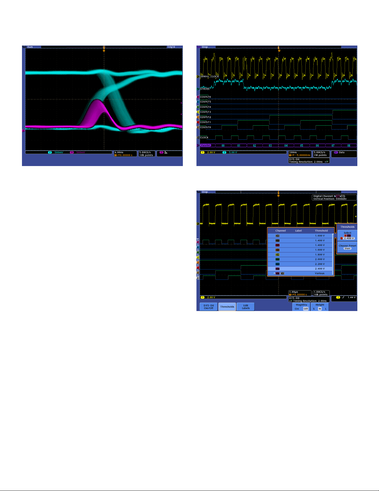
The MSO Series provides 16 integrated digital channels enabling you to view and analyze
time-correlated analog and digital signals.
Accurate High-speed Probing
The TPP S
Series oscilloscope, provide up to 1 GHz of analog bandwidth, and less
than 4 pF of capacitive loading. The extremely low capacitive loading
minimizes adverse affects on your circuits and is more forgiving of longer
ground leads. And, since the probe ban dwidth matches your oscilloscope
bandwidth, you can see the high-frequency components in your signal
which is
voltage probes offer all the benefits of general-purpose probes like high
dynamic range, flexible connection options, and robust mechanical design,
while providing the performance of active probes.
eries probes, included standard with every MSO/DPO4000B
critical for high-speed applications. The TPP Series passive
Mixed Sig nal Design and Analysis
(MSO Series)
The MSO
channels. These channels are tightly integrated into the oscilloscope’s user
4000B Series Mixed Signal Oscilloscopes provide 16 digital
With the color-coded digital waveform display, groups are created by simply placing digital
channels together on the screen, allowing the digital channels to be moved as a group.
You can set threshold values for each channel, enabling support for up to 16 different
logic families.
interface, simplifying operation and making it possible to solve mixed-signal
issues easily.
Color-coded Digital Waveform Display
The MSO4000B Series has redefined the way you view digital waveforms.
One common problem shared by both logic analyzers and mixed signal
oscilloscopes is determining if data is a one or a zero when zoomed in far
enough that the digital trace stays flat all the way across the display. The
MSO4000
B Series has color-coded digital traces, displaying ones in green
and zeros in blue.
www.tektronix.com 5
Data Sheet
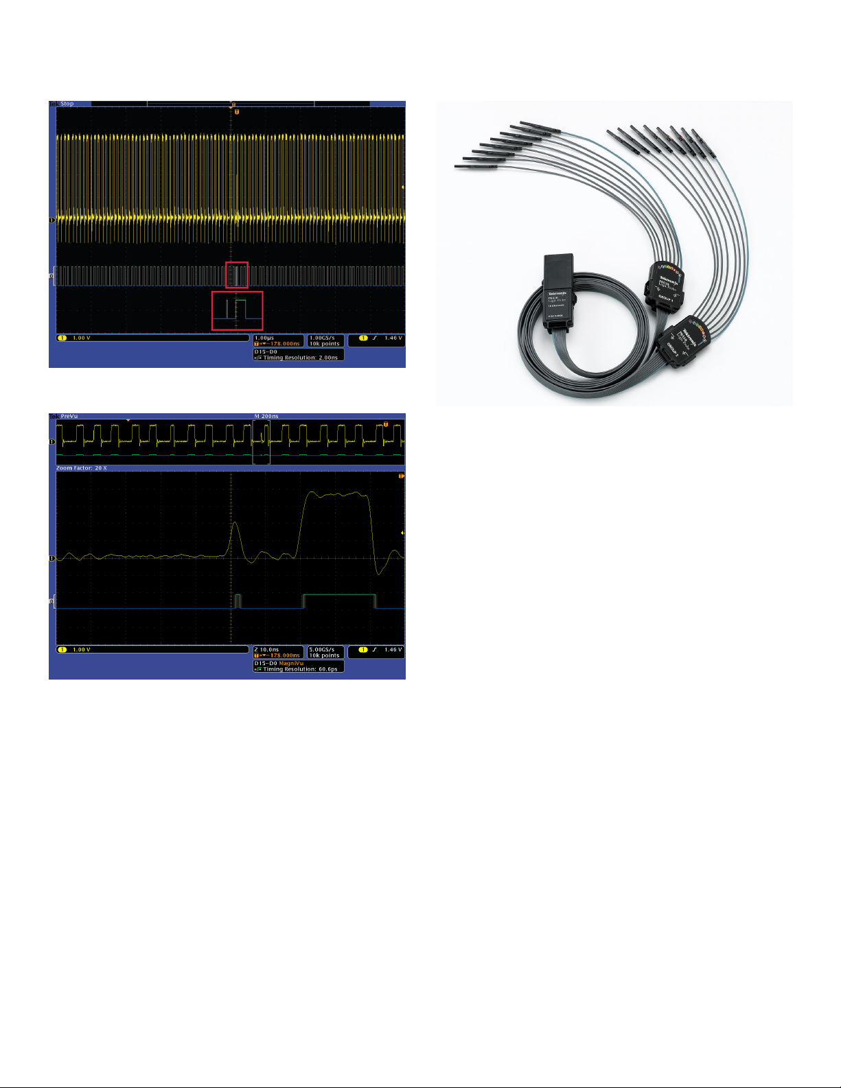
White edges indicate additional information is available by zooming in. As shown here,
zooming in on the white edge reveals a hidden glitch.
The P6616 MSO probe offers two eight-channel pods to simplify connecting to your
device.
gniVu high-resolution record provides 60.6 ps timing resolution, enabling you to
The Ma
ritical timing measurements on your digital waveforms.
make c
The multiple transition detection hardware of the MSO4000B Series will
show you a white edge on the display when the system detects multiple
transitions. White edges indicate that more information is available by
zooming in or acquiring at faster sampling rates. In most cases zooming in
reveal the pulse t hat was not viewable with the previous settings. If the
will
white edge is still present after zooming in as far as possible, this indicates
that increasing the sample rate on the next acquisition will reveal higher
frequency information than the previous settings could acquire.
The MSO40
00B Series simp lifies channel setup by allowing you to group
digital waveforms and enter waveform labels by using a USB keyboard.
By simply placing digital waveforms next to each other, they form a group.
Once a group is formed, you can position all the channels contained in that
group collectively. This greatly reduces the normal setup time associated
with positioning channels individually.
MagniVu™ High-speed Acquisition
The main digital acquisition mode on the MSO4000B Series will capture
up to 20M points at 500 MS/s (2 ns resolution). In addition to the main
the MSO4000B Series provides an ultra high-resolution record
record,
called MagniVu which acquires 10,000 points at up to 16.5 GS/s (60.6 ps
resolution). Both main and MagniVu waveforms are acquired on every
trigger and can be switched between in the display at any time, run ning
or stopped. MagniVu provides significantly finer timing resolution than
comparable MSOs on the market, instilling confidence when making critical
easurements on digital waveforms.
timing m
P6616 M
SO Probe
This unique probe design offers two eight-channel pods. Each channel ends
robe tip featuring a recessed ground for simplified connection to the
with a p
device under test. The coax on the first channel of each pod is colored blue
making it easy to identify. The common ground uses an automotive-style
connector making it easy to create custom grounds for co nnecting to
the device under test. When connecting to square pins, the P66 16 has
an adapter that attaches to the probe head extending the probe ground
th the probe tip so you can attach to a head er. The P6616 offers
flush wi
outstanding electrical characteristics, having only 3 pF of capacitive loading,
a 100 kΩ input resistance, and capable of acq uiring toggle rates >500 MHz
and pulses as short as 1 ns in duration.
6 www.tektronix.com
 Loading...