


x
MSO4000 and DPO4000 Series
Digital Phosphor Oscilloscopes
ZZZ
User Manual
*P071212104*
071-2121-04


xx
MSO4000 and DPO4000 Series
Digital Phosphor Oscilloscopes
ZZZ
User Manual
www.tektronix.com
071-2121-04

Copyright © Tektronix. All rights reserved. Licensed software products are owned by Tektronix or its subsidiaries or suppliers, and are
protected by na
tional copyright laws and international treaty provisions.
Tektronix pro
previously published material. Specifications and price change privileges reserved.
TEKTRONIX and TEK are registered trademarks of Tektronix, Inc.
e*Scope, iView, OpenChoice, TekSecure, and TekVPI are registered trademarks of Tektronix, Inc.
MagniVu and Wave Inspector are trademarks of Tektronix, Inc.
Tektronix is an authorized licensee of the CompactFlash® trademark.
PictBridge is a registered trademark of the Standard of Camera & Imaging Products Association CIPA DC-001-2003 Digital Photo
Solutions for Imaging Devices.
Contactin
Tektronix, Inc.
14200 SW Karl Braun Drive
P.O. Box 500
Beaverton, OR 97077
USA
For product information, sales, service, and technical support:
In North America, call 1-800-833-9200.
Worldwide, visit www.tektronix.com to find contacts in your area.
ducts are covered by U.S. and foreign patents, issued and pending. Information in this publication supersedes that in all
g Tektronix

MSO4000 and DPO 4000 Series Oscilloscopes
Warranty
Tektronix warrants that the product will be free from defects in materials and workmanship for a period of three (3) years from the date
of original pu
option, either will repair the defective product without charge for parts and labor, or will provide a replacement in exchange for the
defective product. Batteries are excluded from this warranty. Parts, modules and replacement products used by Tektronix for warranty
work may be ne
rchase from an authorized Tektronix distributor. If the product proves defective during this warranty period, Tektronix, at its
w or reconditioned to like new performance. All r eplaced parts, modules and products become the property of Tektronix.
In order to ob
period and make suitable arrangements for the performance of s ervice. Customer shall be responsible for packaging and shipping
the defective product to the service center designated by Tektronix, shipping charges prepaid, and with a copy of customer proof of
purchase. T
the Tektronix service center is located. Customer shall be responsible for paying all shipping charges, duties, taxes, and any other
charges for products returned to any other locations.
This warranty shall not apply to any defect, failure or damage caused by improper use or improper or inadequate maintenance and
care. Tekt
other than Tektronix representatives to install, repair or service the product; b) to repair damage resulting from improper use or
connection to incompatible equipment; c) to repair any damage or malfunction caused by the use of non-Tektronix supplies; or
d) to serv
increases the time or difficulty of servicing the product.
THIS WARRANTY IS GIVEN BY TEKTRONIX W ITH RESPECT TO THE PRODUCT IN LIEU OF ANY OTHER WARRANTIES,
EXPRESS OR IMPLIED. TEKTRONIX AND ITS VENDORS DISCLAIM ANY IMPLIED WARRANTIES OF MERCHANTABILITY OR
FITNESS
IS THE SOLE AND E XCLU S IVE REMEDY PROVIDED TO THE CU STOMER FOR BREACH OF THIS WARRANTY. TEKTRONIX
AND ITS VENDORS WILL NOT BE LIABLE FOR ANY INDIRECT, SPECIAL, INCIDENTAL, OR CONSEQUENTIAL DAMAGES
IRRESPE
DAMAGES.
[W16 – 15AUG04]
tain service under this warranty, Customer must notify Tektronix of the defect before the expiration of the warranty
ektronix shall pay for the return of the product to Customer i f the shipment is to a location within the country in which
ronix shall not be obligated to furnish service under this warranty a) to repair damage resulting from attempts by personnel
ice a product that has been modified or integrated with other products when the effect of such modification or integration
FOR A PARTICULAR PURPOSE. TEKTRONIX’ RESPONSIBILITY TO REPAIR OR REPLACE DEFECTIVE PRODUCTS
CTIVE OF WHETHER TEKTRONIX OR THE VENDOR HAS ADVANCE NOTICE OF THE POSSIBILITY OF SUCH

P6516 Probe
Warranty
Tektronix warrants that the product will be free from defects in materials and workmanship for a period of one (1) year from the date of
original purc
option, either will repair the defective product without charge for parts and labor, or will provide a replacement in exchange for the
defective product. Batteries are excluded from this warranty. Parts, modules and replacement products used by Tektronix for warranty
work may be ne
hase from an authorized Tektronix distributor. If the product proves defective during this warranty period, Tektronix, at its
w or reconditioned to like new performance. All replaced parts, modules and products become the property of Tektronix.
In order to ob
period and make suitable arrangements for the performance of service. Customer shall be responsible for packaging and shipping
the defective product to the service center designated by Tektronix, shipping charges prepaid, and with a copy of customer proof of
purchase. T
the Tektronix service center is located. Customer shall be responsible for paying all shipping charges, duties, taxes, and any other
charges for products returned to any other locations.
This warranty shall not apply to any defect, failure or damage caused by improper use or improper or inadequate maintenance and
care. Tekt
other than Tektronix representatives to install, repair or service the product; b) to repair damage resulting from improper use or
connection to incompatible equipment; c) to repair any damage or malfunction caused by the use of non-Tektronix supplies; or
d) to serv
increases the time or difficulty of servicing the product.
THIS WARRANTY IS GIVEN BY TEKTRONIX WITH RESPECT TO T HE PRODUCT IN LIEU OF ANY OTHER WARRANTIES,
EXPRESS OR IMPLIED. TEKTRONIX AND ITS VENDORS DISCLAIM ANY IMPLIED WARRANTIES OF MERCHANTABILITY OR
FITNESS
IS THE SOLE AND EXCLUSIVE REMEDY PROVIDED TO THE CUSTOMER FOR BREACH OF T HIS WARRANTY. TEKTRONIX
AND ITS VENDORS WILL NOT BE LIABLE FOR ANY INDIRECT, SPECIAL, INCIDENTAL, OR CONSEQUENTIAL DAMAGES
IRRESPE
DAMAGES.
[W15 – 15AUG04]
tain service under this warranty, Customer must notify Tektronix of the defect before the expiration of the warranty
ektronix shall pay for the return of the product to Customer if the shipment is to a location within the country in which
ronix shall not be obligated to furnish service under this warranty a) to repair damage resulting from attempts by personnel
ice a product that has been modifi ed or integrated with other products when the effect of such modification or integration
FOR A PARTICULAR PURPOSE. TEKTRONIX’ RESPONSIBILITY TO REPAIR OR REPLACE DEFECTIVE PRODUCTS
CTIVE OF WHETHER TEKTRONIX OR THE VE NDOR HAS ADVANCE NOTICE OF THE POSSIBILITY OF SUCH

P6139A Probe
Warranty
Tektronix warrants that this product will be free from defects in materials and workmanship for a period of one (1) year from the date of
shipment. If a
product without charge for parts and labor, or will provide a replacement in exchange for the defective product. Parts, modules and
replacement products used by Tektronix for warranty work may be new or reconditioned to like new performance. All replaced
parts, modul
ny such product proves defective during this warranty period, Tektronix, at its option, either will repair the defective
es and products become the property of Tektronix.
In order to ob
and make suitable arrangements for the performance of service. Customer shall be responsible for packaging and shipping the
defective product to the service center designated by Tektronix, with shipping charges prepaid. Tektronix shall pay for the return of the
product to C
be responsible for paying all shipping charges, duties, taxes, and any other charges for products returned to any other locations.
This warranty shall not apply to any defect, failure or damage caused by improper use or improper or inadequate maintenance and
care. Tektronix shall not be obligated to furnish service under this warranty a) to repair damage resulting from a ttempts by personnel
other than
connection to incompatible equipment; c) to repair any damage or malfunction caused by the use of non-Tektronix supplies; or
d) to service a product that has been modified or integrated with other products when the effect of such modification or integration
increase
THIS WARR
EXPRESS OR IMPLIED. TEKTRONIX AND ITS VENDORS DISCLAIM ANY IMPLIED WARRANTIES OF MERCHANTABILITY OR
FITNESS FOR A PARTICULAR PURPOSE. TEKTRONIX’ RES PON SIBILITY TO REPAIR OR REPLACE DEFECTIVE PRODUCTS
IS THE SO
AND ITS VENDORS WILL NOT BE LIABLE FOR ANY INDIRECT, SPECIAL, INCIDENTAL, OR CONSEQUENTIAL DAMAGES
IRRESPECTIVE OF WHETHER TEKTRONIX OR THE VENDOR HAS ADVANCE NOTICE OF THE POSSIBILITY OF SUCH
DAMAGES
[W2 – 15
tain service under this warranty, Customer must notify Tektronix of the defect before the expiration of the warranty period
ustomer if the shipment is to a location within the country in which the Tektronix service center is located. Customer shall
Tektronix representatives to install, repair or service the product; b) to repair damage resulting from improper use or
s the time or difficulty of servicing the product.
ANTY IS GIVEN BY TEKTRONIX WITH RESPECT TO THE PROD UCT IN LIEU OF ANY OTHER WARRANTIES,
LE AND EXCLUSIVE REMEDY PROV IDED TO THE CUSTOMER FOR BREACH OF THIS WARRANTY. TEKTRONIX
.
AUG04]


Table of Contents
General Safety Summary ... .. . .. . . . .. . .. .. . .. .. . .. .. . .. .. . .. . .. .. . .. .. . .. .. . .. .. . .. . . . .. ... .. . .. .. . .. .. . .. .. . .. ... .. . . . .. . .. .. . .. .. .. v
Compliance Information .............................................................................................................. vii
EMC Compliance................................................................................................................ vii
Safety Compliance ............................................................................................................... ix
Environmental Considerations................................................................................................... xi
Preface................................................................................................................................ xii
Key Features................................................................................................................... xiii
Conventions Used in This Manual.. .. . .. . .. .. . .. .. . .. .. . .. .. . .. .. . .. .. . .. . .. .. . .. .. . .. .. . .. .. . .. .. . .. .. . .. . .. .. . .. .. . .. .. . .. .. xiii
Installation.............................................................................................................................. 1
Before Installation ................................................................................................................ 1
Operating Considerations........................................................................................................ 6
Connecting Probes. .. .. . .. .. . .. . .. .. . .. .. . .. ... .. . .. .. . .. .. . .. . .. .. . .. .. . .. ... .. . .. .. . .. . . . .. . .. .. . .. .. . .. . .. .. . .. .. . .. ... .. . .. .. 9
Securing the Oscilloscope ...................................................................................................... 10
Powering On theOscilloscope ................................................................................................. 11
Powering Off the Oscilloscope.................................................................................................. 12
Functional Check. .. . .. . . . .. . .. .. . .. .. . .. . . . .. . .. .. . .. .. . .. . . . .. . .. .. . .. ... .. . .. .. . .. .. . .. ... .. . .. .. . .. .. . .. ... .. . .. .. . .. .. . .. . .. 12
Compensating a Passive Voltage Probe . ... .. . .. .. . .. .. . .. .. . .. .. . .. . . . .. ... .. . .. .. . .. .. . .. .. . .. .. . .. . . . .. . .. .. . .. .. . .. .. . .. .. 13
Application Module Free Trial... .. . .. .. . .. .. . .. .. . .. .. . .. .. . .. .. . .. .. . .. .. . .. .. . .. .. . .. .. . .. .. . .. .. . .. .. . .. .. . .. .. . .. .. . .. .. . . . . 14
Installing an Application Module. . .. .. . .. . .. .. . . . .. ... .. . .. .. . .. .. . .. .. . .. .. . .. .. . .. .. . .. .. . .. .. . .. .. . .. .. . .. .. . .. .. . .. .. . .. .. . . 15
Changing the User Interface Language . .. . .. .. . .. .. . .. ... .. . .. .. . .. .. . .. . .. .. . .. .. . .. ... .. . .. .. . .. . . . .. . .. .. . .. .. . .. . .. .. . .. .. 15
Changing the Date and Time .. . .. . . . .. . .. .. . .. . .. .. . .. .. . .. . .. .. . .. ... .. . .. .. . .. ... .. . .. .. . .. . .. .. . .. .. . .. . .. .. . .. . . . .. . .. .. . .. 16
Signal Path Compensation . .. . .. .. . .. .. . .. . . . .. ... .. . .. .. . .. .. . .. .. . .. ... .. . . . .. . .. .. . .. .. . .. .. . .. ... .. . .. .. . .. .. . .. .. . .. ... .. . 18
Upgrading Firmware ............................................................................................................ 19
Connecting Your Oscilloscope to a Computer ... .. . .. .. . .. .. . .. .. . .. .. . .. .. . .. . .. .. . .. .. . .. .. . .. .. . .. .. . .. .. . .. . .. .. . .. .. . .. .. 22
Connecting a USB Keyboard to Your Oscilloscope. . .. .. . .. .. . .. .. . .. . .. .. . .. .. . .. .. . .. ... .. . . . .. . .. .. . .. .. . .. . . . .. . .. .. . .. .. . 26
Get Acquainted with the Instrument ................................................................................................. 27
Front-Panel Menus and Controls. . . . .. . .. .. . .. .. . .. .. . .. .. . .. .. . .. .. . .. .. . .. . .. .. . .. .. . .. .. . .. .. . .. .. . .. .. . .. .. . .. . . . .. ... .. . .. 27
Front-Panel Connectors ... .. . .. .. . .. .. . .. .. . .. .. . .. . . . .. ... .. . .. .. . .. .. . .. .. . .. .. . .. .. . .. .. . .. . .. .. . . . .. . .. .. . .. .. . .. .. . .. .. . .. 38
Side-Panel Connector... .. . .. .. . .. . . . .. . .. .. . .. .. . .. . .. .. . .. .. . .. . .. .. . .. .. . .. .. . .. . .. .. . .. .. . .. ... .. . .. .. . .. . . . .. . .. .. . .. .. . .. . 38
Rear-Panel Connectors. .. . .. .. . .. .. . .. .. . .. . .. .. . .. .. . .. .. . .. .. . .. .. . .. .. . .. .. . .. . . . .. ... .. . .. .. . .. .. . .. .. . .. .. . .. .. . .. .. . .. . .. 39
ire the Signal ... .. . .. ... .. . . . .. . .. .. . .. .. . .. .. . .. .. . .. .. . .. . . . .. .. . .. . .. .. . .. .. . .. .. . .. .. . .. .. . .. .. . .. .. . .. . . . .. ... .. . .. .. . .. .. . .40
Acqu
Setting Up Analog Channels.. ... .. . .. .. . .. . . . .. . .. .. . .. .. . .. . . . .. . .. .. . .. .. . .. . . . .. . .. .. . .. .. . .. . . . .. . .. .. . .. ... .. . .. .. . .. .. . .. 40
Using the Default Setup......................................................................................................... 43
Using Autoset ................................................................................................................... 44
Acquisition Concepts............................................................................................................ 45
How the Analog Acquisition Modes Work.. .. . .. .. . .. .. . .. . .. .. . .. .. . .. .. . .. .. . .. . . . .. . .. .. . .. .. . .. . . . .. ... .. . .. .. . .. .. . .. .. . .. 46
Changing the Acquisition Mode, Record Length, and Delay Time. .. . .. ... .. . .. .. . .. .. . .. ... .. . .. .. . .. .. . .. . .. .. . .. .. . .. .. . .. 47
Using Roll Mode................................................................................................................. 49
Setting Up a Serial or Parallel Bus ............................................................................................. 50
Setting Up Digital Channels . .. . . . .. ... .. . .. .. . .. .. . .. .. . .. .. . .. . . . .. ... .. . .. .. . .. .. . .. .. . .. .. . .. . . . .. ... .. . .. .. . .. .. . .. .. . .. .. . 62
When and Why to Turn On MagniVu. .. . .. . . . .. . .. .. . .. . .. .. . .. . .. .. . .. ... .. . .. .. . .. . .. .. . .. ... .. . .. ... .. . .. .. . .. . .. .. . .. . .. .. . 64
Using MagniVu .................................................................................................................. 64
Table of Content
s
MSO4000 and DPO4000 Series Oscilloscopes User Manual i

Table of Content
Trigger Setup . .. . .. .. . .. .. . .. ... .. . . . .. . .. .. . .. .. . .. .. . .. .. . .. . .. .. . .. .. . .. .. . .. .. . .. . . . .. . .. .. . .. .. . .. .. . .. .. . .. . .. .. . .. .. . .. .. ...... 66
Display Waveform Data .............................................................................................................. 81
Analyze Waveform Data. . .. . . . .. ... .. . .. .. . .. .. . .. .. . .. ... .. . . . .. . .. .. . .. .. . .. .. . .. .. . .. . .. .. . .. .. . .. .. . .. .. . .. . . . .. . .. .. . .. .. . .. .. .. 95
Save and Recall Information ....................................................................................................... 122
Using Application Modules .. .. . . . .. . .. .. . .. .. . .. .. . .. .. . .. ... .. . . . .. . .. .. . .. .. . .. .. . .. .. . .. ... .. . . . .. . .. .. . .. .. . .. .. . .. .. . .. ... .. . .137
Application Examples............................................................................................................... 138
s
Triggering Concepts............................................................................................................. 66
Choosing a Trigger Type . .. .. . .. .. . .. . . . .. . .. .. . .. .. . .. . . . .. . .. .. . .. .. . .. . . . .. ... .. . .. .. . .. .. . .. ... .. . .. .. . .. .. . .. ... .. . .. .. . .. . 69
Selecting Triggers. . .. .. . .. .. . .. .. . .. .. . .. . .. .. . .. .. . .. .. . .. .. . .. .. . .. .. . .. .. . .. . . . .. ... .. . .. .. . .. .. . .. .. . .. .. . .. .. . .. .. . .. ... .. .70
Triggering on Buses............................................................................................................. 72
Checking Trigger Settings .. .. . .. .. . .. .. . .. . . . .. .. . .. ... .. . . . .. ... .. . .. .. . . . .. . .. .. . .. .. . .. .. . .. .. . .. .. . .. .. . .. .. . .. .. . .. .. . .. .. 78
Using Sequence Trigger (A (Main) and B (Delayed)). . . . .. ... .. . .. .. . .. .. . .. ... .. . .. .. . .. .. . .. ... .. . .. .. . .. .. . .. .. . .. . .. .. . .. . 78
Starting and Stopping an Acquisition. .. . .. . . . .. ... .. . .. .. . .. .. . .. .. . .. .. . .. . . . .. . .. .. . .. .. . .. .. . .. .. . .. .. . .. . . . .. . .. .. . .. .. . .. . 80
Adding and Removing a Waveform .. . .. . .. .. . .. .. . .. .. . .. .. . .. . . . .. . .. .. . .. .. . .. .. . .. .. . .. . .. .. . .. .. . .. .. . .. .. . .. . . . .. . .. .. . .. 81
Setting the Display Style and Persistence ..................................................................................... 81
Setting Waveform Intensity ..................................................................................................... 84
Scaling and Positioning a Waveform........................................................................................... 85
Setting Input Parameters . . .. ... .. . .. .. . .. .. . .. .. . .. .. . .. ... .. . .. .. . .. .. . .. .. . .. ... .. . . . .. . .. .. . .. .. . .. .. . .. .. . .. . .. .. . .. .. . .. .. 86
Positioning and Labeling Bus Signals. . .. ... .. . .. .. . .. .. . .. .. . .. .. . .. . . . .. ... .. . .. .. . .. .. . .. .. . .. .. . .. . . . .. ... .. . .. .. . .. .. . .. .. 90
Positioning, Scaling, and Grouping Digital C hannels .. . .. ... .. . . . .. . .. .. . .. .. . .. .. . .. .. . .. . .. .. . . . .. . .. .. . .. .. . .. .. . .. .. . .. . .. 91
Viewing Digital Channels . . .. .. . .. .. . .. .. . .. .. . .. . . . .. ... .. . .. .. . .. .. . .. .. . .. .. . .. .. . .. .. . .. . .. .. . . . .. . .. .. . .. .. . .. .. . .. .. . .. .. . 92
Annotating the Screen .. . .. ... .. . .. .. . .. .. . .. .. . .. . .. .. . .. .. . .. .. . .. ... .. . . . .. . .. .. . .. .. . .. . . . .. ... .. . .. .. . .. .. . .. .. . .. . .. .. . .. . 93
Viewing the Trigger Frequency ... . .. .. . .. . .. .. . .. ... .. . .. .. . .. .. . .. . .. .. . .. .. . .. ... .. . .. .. . .. . . . .. . .. .. . .. . .. .. . .. .. . .. ... .. . .. 94
Taking Automatic Measurements............................................................................................... 95
Selecting Automatic Measurements............................................................................................ 96
Customizing anAutomatic Measurement .................................................................................... 100
Taking Manual Measurements with Cursors .. ... .. . .. .. . .. .. . .. . .. .. . .. .. . .. .. . .. . .. .. . .. .. . .. ... .. . .. .. . .. . . . .. . .. .. . .. ... . 103
Setting Up a Histogram ....................................................................................................... 107
Using Math Waveforms ....................................................................................................... 110
Using FFT ...................................................................................................................... 111
Using Advanced Math......................................................................................................... 113
Using Reference Waveforms................................................................................................. 114
Using Wave Inspector to Manage Long Record Length Waveform
Analyzing Power . .. . .. . . . .. . .. .. . .. ... .. . .. .. . .. .. . .. ... .. . .. .. . .. .. . .. ... .. . .. .. . .. .. . .. . .. .. . .. .. . .. .. . .. . .. .. . .. .. . .. .. . .. . 121
Saving a Screen Image ....................................................................................................... 124
Saving and Recalling Waveform Data........................................................................................ 125
Saving and Recalling Setups ................................................................................................. 127
Saving with One Button Push ................................................................................................ 129
Printing a Hard Copy.......................................................................................................... 130
Erasing Oscilloscope Memory ................................................................................................ 135
Taking SimpleMeasurements ................................................................................................ 138
Analyzing Signal Detail . .. . .. .. . .. .. . .. .. . .. .. . .. . . . .. ... .. . .. .. . .. .. . .. .. . .. .. . .. . . . .. ... .. . .. .. . .. .. . .. .. . .. .. . .. . . . .. ... .. . 145
Triggering on a Video Signal. .. . . . .. . .. .. . .. .. . .. .. . .. .. . .. . .. .. . .. .. . .. .. . .. .. . .. . . . .. . .. .. . .. .. . .. .. . .. .. . .. . .. .. . .. .. . .. .. . 149
Capturing a Single-Shot Signal.. . .. .. . .. .. . .. .. . .. ... .. . .. .. . .. .. . .. .. . .. . .. .. . .. .. . .. .. . .. ... .. . . . .. . .. .. . .. .. . .. . . . .. . .. .. . 151
Correlating Data with a TLA5000 Logic Analyzer. . .. .. . .. ... .. . . . .. . .. .. . .. .. . .. . . . .. ... .. . .. .. . .. .. . .. .. . .. . .. .. . .. .. . .. .. . 154
s........................................................ 116
ii MSO4000 and DPO4000 Series Oscilloscopes User Manual

Table of Content
Tracking Down Bus Anomalies ... .. . .. .. . .. . .. .. . .. .. . .. ... .. . .. .. . .. . . . .. . .. .. . .. .. . .. . .. .. . .. .. . .. ... .. . .. .. . .. .. . .. . .. .. . . 156
Troubleshooti
ng Circuits Using Parallel Buses .............................................................................. 158
Troubleshooting an RS-232 Bus . .. .. . .. .. . .. . . . .. . .. .. . .. ... .. . .. .. . .. .. . .. ... .. . .. .. . .. .. . .. . .. .. . .. .. . .. .. . .. . .. .. . .. .. . .. 160
Appendix: Warranted Specifications............................................................................................... 162
Index
s
MSO4000 and DPO4000 Series Oscilloscopes User Manual iii

Table of Content
s
iv MSO4000 and DPO4000 Series Oscilloscopes User Manual

General Safety S
ummary
General Safet
Review the following safety precautions to avoid injury and prevent damage to this product or any products connected to it.
To avoid potential hazards, use this product only as specified.
Only qualified personnel should perform service procedures.
To Avoid Fire or Personal Injury
Use Proper Power Cord. Use only the power cord specified for this product and certified for the country of use.
Connect and Disconnect Properly. Do not connect or disconnect probes or test leads while they are connected
to a voltage source.
Connect and Disconnect Properly. De-energize the circuit under test before connecting or disconnecting the current
probe.
Ground th
shock, the grounding conductor must be connected to earth ground. Before making connections to the input or output
terminals of the product, ensure that the product is properly grounded.
Observe All Terminal Ratings. To avoid fire or shock hazard, observe all ratings and markings on the product. Consult
the prod
The inpu
e Product.
uct manual for further ratings information before making connections to the product.
ts are not rated for connection to mains or Category II, III, or IV circuits.
y Summary
This product is grounded through the grounding conductor of the power cord. To avoid electric
Connect
Do not a
Power D
Do not block the power switch; it must remain accessible to the user at all times.
the probe reference lead to earth ground only.
pply a potential to any terminal, including the common terminal, that exceeds the maximum rating of that terminal.
isconnect.
The power switch disconnects the product from the power source. See instructions for the location.
Do Not Operate Without Covers. Do not operate this product with covers or panels removed.
Do Not Operate With Suspected Failures. If you suspect that there is damage to this product, have it inspected by
qualified service personnel.
Avoid Exposed Circuitry. Do not touch exposed connections and components when power is present.
Do Not Operate in Wet/Damp Conditions.
Do Not Operate in an Explosive Atmosphere.
Keep Product Surfaces Clean and Dry.
Provide Proper Ventilation.
per ventilation.
pro
Refer to the manual’s installation instructions for details on installing the product so it has
MSO4000 and DPO4000 Series Oscilloscopes User Manual v
General Safety S
TermsinthisManual
These terms may appear in this manual:
WARNING. Warning statements identify conditions or practices that could result in injury or loss of life.
CAUTION. Caution statements identify conditions or practices that could r esult in damage to this product or other property.
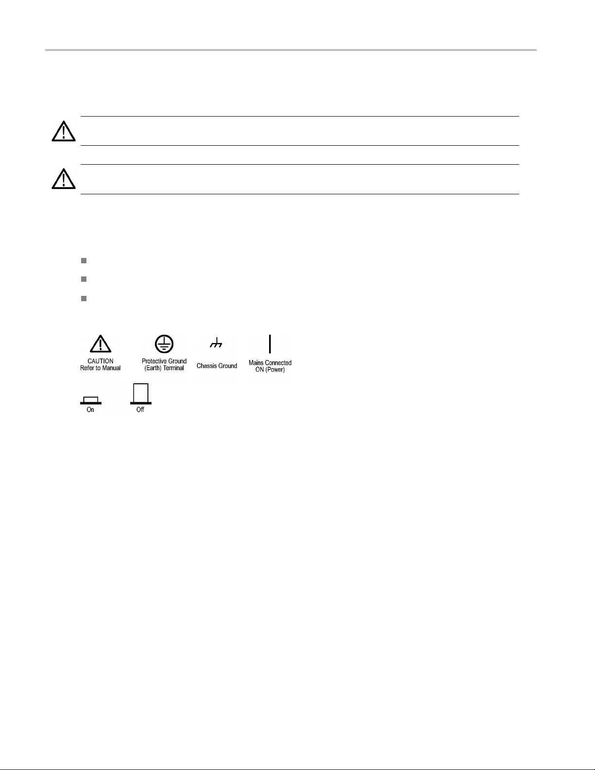
Symbols and Terms on the Product
These terms may appear on the product:
DANGER indicates an injury hazard immediately accessible as you read the marking.
WARNING indicates an injury hazard not immediately accessible as you read the marking.
CAUTION indicates a hazard to property including the product.
The following symbol(s) may appear on the product:
ummary
vi MSO4000 and DPO4000 Series Oscilloscopes User Manual

Compliance Info
rmation
Compliance In
This section lists the EMC (electromagnetic compliance), safety, and environmental standards with which the instrument
complies.
EMC Compliance
EC Declaration of Conformity – EMC
Meets intent of Directive 2004/108/EC for Electromagnetic Compatibility. Compliance was demonstrated to the following
specifications as listed in the Official Journal of the European Communities:
EN 61326-1:2006, EN 61326-2-1:2006. EMC requirements for electrical equipment for measurement, control, and
laboratory use.
CISPR 11:2003. Radiated and conducted emissions, G roup 1, Class A
IEC 61000-4-2:20
IEC 61000-4-3:2002. RF electromagnetic field immunity
IEC 61000-4-4:2004. Electrical fast transient/burst immunity
IEC 61000-4-5:2001. Power line surge immunity
IEC 61000-4-6:2003. Conducted RF immunity
IEC 61000-4-11:2004. Voltage dips and interruptions immunity
1234
formation
01. Electrostatic discharge immunity
5
6
7
EN 61000-3-2:2006. AC power line harmonic emissions
EN 61000-3-3:1995. Voltage changes, fluctuations, and flicker
European Contact.
Tektronix UK, Ltd.
Western Peninsula
Western Road
Bracknell, RG12 1RF
United Kingdom
1
This product is i ntended for use in nonresidential areas only. Use in residential areas may cause electromagnetic interference.
2
Emissions which exceed the levels required by this standar
3
To ensure compliance with the EMC standards listed here, high quality shielded interface cables should be used.
4
Instrument rebooting may be experienced where the EUT takes longer than 10 seconds to recover from a transient immunity test.
5
The increase in trace noise while subjected to the test field (3 V/m over the frequency range 80 MHz to 1 GHz, 1.4 GHz to 2.0 GHz, and
1 V/m from 2.0 GHz to 2.7 GHz, with 80% amplitude modulation at 1 kHz) is not to exceed 8 major division(s) peak-to-peak. Ambient
fields may induce triggering when trigger threshold is offset less than 4 major divisions from ground reference (IEC 61000-4-3).
6
The increase in trace noise wh
fields may induce triggering when trigger threshold is offset less than 1 major division from ground reference (IEC 61000-4-6).
7
Performance Criterion C applied at the 70%/25 cycle Voltage-Dip and the 0%/250 cycle Voltage-Interruption test levels
(IEC 61000-4-11).
ile subjected to the injected 3 V test signal is not to exceed 2 major divisions peak-to-peak. Ambient
d may occur when this equipment is connected to a test object.
MSO4000 and DPO4000 Series Oscilloscopes User Manual vii

Compliance Info
Australia / New Zealand Declaration of Conformity – EMC
Complies with the EMC provision of the Radiocommunications Act per the following standard, in accordance with ACMA:
CISPR 11:2003. Radiated and Conducted Emissions, Group 1, Class A, in accordance with EN 61326-1:2006 and
EN 61326-2-1:2006.
rmation
viii MSO4000 and DPO4000 Series Oscilloscopes User Manual

Safety Compliance
EC Declaration of Conformity – Low Voltage
Compliance was demonstrated to the following specification as listed in the Official Journal of the European Communities:
Low Voltage Directive 2006/95/EC.
EN 61010-1: 2001. Safety requirements for electrical equipment for measurement control and laboratory use.
Compliance Info
rmation
U.S. Nation
UL 61010-1:2004, 2ndEdition. Standard for electrical measuring and test equipment.
ally Recognized Testing La boratory Listing
Canadian Certification
CAN/CSAlaboratory use. Part 1.
C22.2 No. 61010-1:2004. Safety requirements for electrical equipment for measurement, control, and
Additional Compliances
IEC 61010-1: 2001. Safety requirements for electrical equipment for measurement, control, and laboratory use.
Equipment Type
Test and measuring equipment.
y Class
Safet
Class 1 – grounded product.
Pollution Degree Description
asure of the contaminants that could occur in the environment around and within a p roduct. Typically the internal
Ame
environment inside a product is considered to be the same as the external. Products should be used only in the environment
for which they are rated.
Pollution Degree 1. No pollution or only dry, nonconductive pollution occurs. Products in this category are generally
capsulated, hermetically sealed, or located in clean rooms.
en
llution Degree 2. Normally only dry, nonconductive pollution occurs. Occasionally a temporary conductivity that is
Po
caused by condensation must be expected. This location is a typical office/home environment. Temporary condensation
occurs only when the product is out of service.
Pollution Degree 3. Conductive pollution, or dry, nonconductive pollution that becomes conductive due to condensation.
hese are sheltered locations where neither temperature nor humidity is controlled. The area is protected from direct
T
sunshine, rain, or direct wind.
Pollution Degree 4. Pollution that generates persistent conductivity through conductive dust, rain, or snow. Typical
outdoor locations.
MSO4000 and DPO4000 Series Oscilloscopes User Manual ix

Compliance Info
Pollution Degree
Pollution Degree 2 (as defined in IEC 61010-1). N ote: Rated for indoor use only.
Installation (Overvoltage) Category Descriptions
Terminals on this product may have different installation (overvoltage) category designations. The installation categories are:
Measurement Category IV. For measurements performed at the source of low-voltage installation.
Measurement Category III. For measurements performed in the building installation.
Measurement Category II. For measurements performed on circuits directly connected to the low-voltage installation.
Measurement Category I. For measurements performed on circuits not directly connected to MAINS.
rmation
Overvolta
Overvoltage Category I (as defined in IEC 61010-1).
ge Category
x MSO4000 and DPO4000 Series Oscilloscopes User Manual

Environmental Considerations
This section provides information about the environmental impact of the product.
Product End-of-Life Handling
Observe the following guidelines when recycling an instrument or component:
Equipment Recycling. Production of this equipment required the extraction and use of natural resources. The
equipment may contain substances that could be harmful to the environment or human health if improperly handled at the
product’s end of life. In o rder to avoid release of such substances into the environment and to reduce the use of natural
resources, we encourage you to recycle this product in an appropriate system that will ensure that most of the materials are
reused or recycled appropriately.
This symbol indicates that this product complies with the applicable European Union requirements according
to Directives 2002/96/EC and 2006/66/EC on waste electrical and electronic equipment (WEEE) and
batteries. For information about recycling options, check the Support/Service section of the Tektronix Web
site (www.tektronix.com).
Compliance Info
rmation
Mercury N
to environmental considerations. Please contact your local authorities or, within the U nited States, refer to the E-cycling
Central Web page (www.eiae.org) for disposal or recycling information.
Restric
This product has been classified as Monitoring and Control equipment, and is outside the scope of the 2002/95/EC RoHS
Directive.
otification.
tion of Hazardous Substances
This product uses an LCD backlight lamp that contains mercury. Disposal may be regulated due
MSO4000 and DPO4000 Series Oscilloscopes User Manual xi

Preface
Preface
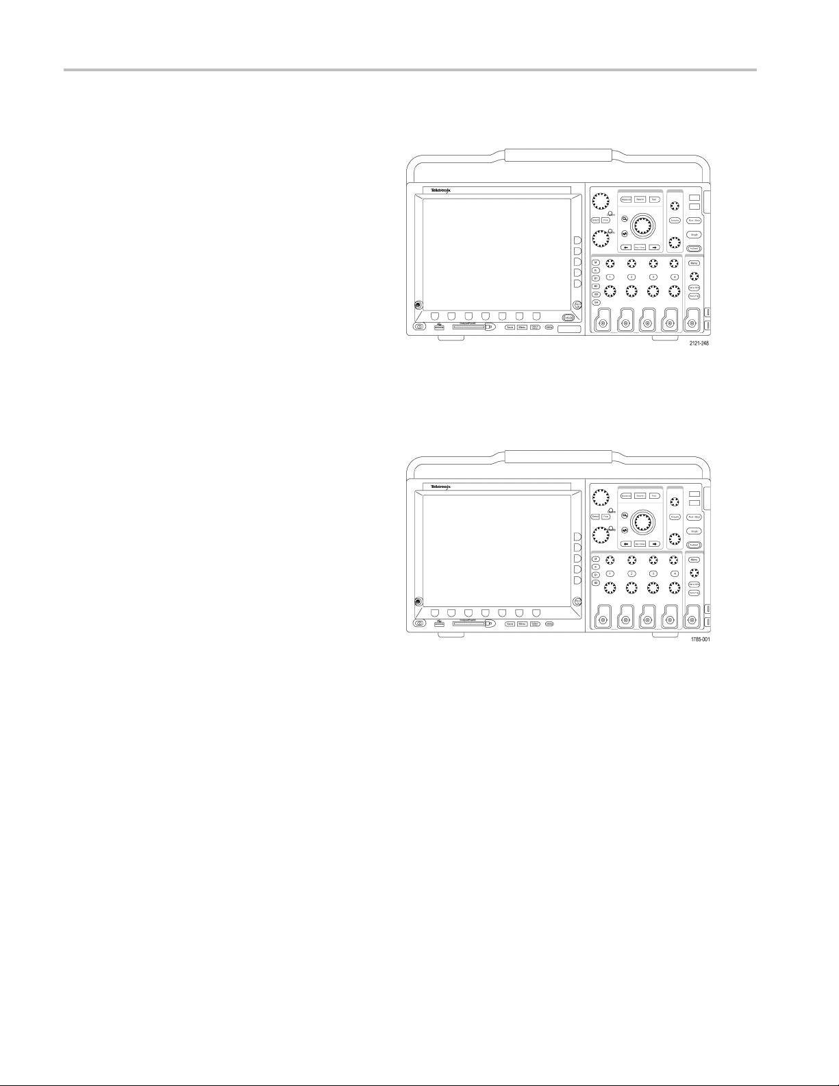
This manual describes the installation and operation of the following oscilloscopes:
MSO4104 MSO4054 MSO4034 MSO4032
DPO4104 DPO4054 DPO4034 DPO4032
xii MSO4000 and DPO4000 Series Oscilloscopes User Manual

Key Features
MSO4000 and DPO4000 Series instruments can help you verify, debug, and characterize electronic designs. Key features
include:
1 GHz, 500 MHz, and 350 MHz bandwidths
2 and 4 channel models
Sample rates up to 5 GS/s on all analog channels
10 M points record length on all channels
50,000 waveforms/second display rate
Preface
I2C, SPI, USB 2.0, CAN, LIN, FlexRay, RS-232, RS-422, RS-485, UART, I2S, Left Just
TDM bus triggering and analysis (with the appropriate application module and oscilloscope model)
Power analysis application module (optional)
Wave Inspector controls for managing long record lengths, with zoom and pan, play and pause, search and mark
Waveform histograms with measurements on histogram data, automatic measurements, and measurement statistics
10.4 inch (264 mm) XGA color display
Small and lightweight, at 5.5 inches (140 mm) deep and 11 pounds (5 kg)
USB and CompactFlash available for quick and easy storage
Direct printing to any PictBridge-compatible printer
Built-in Ethernet port
USB 2.0 device port for d
OpenChoice documentation and analysis software
NI SignalExpress™ Tektronix Edition productivity and analysis software
Remote viewing and control with e*Scope
Remote control with VISA connectivity
TekVPI Versatile Probe Interface supports active, differential, and current probes for automatic scaling and units
irect PC control of the oscilloscope using USBTMC protocol
ified (LJ), Right Justified (RJ), and
MSO4000 Mixed Signal Oscilloscopes also offer:
MagniVu 60.6 ps resolution
Parallel bus triggering and analysis
Per channel threshold settings
16 digital channels
Conventions Used in T his Manual
The following icons are used throughout this manual.
Sequence Step
MSO4000 and DPO4000 Series Oscilloscopes User Manual xiii
Front panel power
Connect power
Network
USB

Preface
xiv MSO4000 and DPO4000 Series Oscilloscopes User Manual

Installation
Before Installation
Unpack the oscilloscope and check that you received all item s listed as standard accessories. The following pages list
recommended accessories and probes, instrument options, and upgrades. Check the Tektronix Web site (www.tektronix.com)
for the most current information.
Standard Accessories
Accessory Description
MSO4000 and DPO4000 Series
Oscilloscopes User Manual
MSO4000 and DPO4000 Series
Oscilloscopes Documentation Browser
CD
NI LabVIEW SignalExpress Tektronix Edition
and Tektronix O penChoice Desktop CD
Calibration certificate documenting
traceability to national metrology institute(s),
and ISO9001 quality system registration.
Front Panel Overlay
For MSO4000 and DPO4000 Series: Probes One, 500 MHz, 10X passive probe per channel
Front Cover
Tektronix part
number
English (Option L0)
French (Option L1)
Italian (Option L2)
German (Option L3)
Spanish (Option L4)
Japanese (Option L5)
Portuguese (Option L6)
Simple Chinese (Option L7)
Traditional Chinese (Option L8)
Korean (Option L9)
Russian (Option L10)
Electronic versions of documents, including
the Programmer M anual and the Technical
Reference.
Productivity, analysis, and documentation
software
French (Option L1)
Italian (Option L2)
German (Option L3)
Spanish (Option L4)
Japanese (Option L5)
Portuguese (Option L6)
Simplified Chinese (Option L7)
Traditional Chinese (Option L8)
Korean (Option L9)
Russian (Option L10)
Hard plastic cover to help protect the instrument 200-4908-00
071-2121-XX
071-2122-XX
071-2123-XX
071-2124-XX
071-2125-XX
071-2126-XX
071-2127-XX
071-2128-XX
071-2129-XX
071-2130-XX
071-2131-XX
063-4022-XX
063-3967-XX
——
335-1634-XX
335-1635-XX
335-1636-XX
335-1637-XX
335-1638-XX
335-1639-XX
335-1640-XX
335-1641-XX
335-1642-XX
335-1643-XX
P6139A
Installation
MSO4000 and DPO4000 Series Oscilloscopes User Manual 1

Installation
Standard Accessories (cont.)
Accessory Description
Power Cord
For MSO4000 Series: Logic probe One, 16-channel logic probe
North America (Opti o n A0)
Universal Euro (Option A1)
United Kingdom (Option A2)
Australia (Option A3)
Switzerland (Option A5)
Japan (Option A6)
China (Option A10)
India (Option A11)
No power cord or AC adapter (Option A99)
Tektronix part
number
161-0104-00
161-0104-06
161-0104-07
161-0104-05
161-0167-00
161-A005-00
161-0306-00
161-0400-00
——
P6516
2 MSO4000 and DPO4000 Series Oscilloscopes User Manual

Optional Accessories
Accessory Description
DPO4AUDIO
DPO4AUTO
The audio serial triggering and analysis module
enables trigg
Right Justified (RJ), and TDM buses.
The automoti
module enables triggering on packet level
information on CAN and LIN serial buses, as
well as digit
bus decoding, search tools, and packet decode
tables with timestamp information
eringonI
2
S, Left Justified (LJ),
ve serial triggering and analysis
al views of the signal, bus views,
Installation
Tektronix part
number
DPO4AUDIO
DPO4AUTO
NOTE. LIN wo
rks on DPO4000s with serial
numbers greater than C020000 and on all
MSO4000s. Oscilloscopes purchased under
GSA contra
ct may use a different serial
number scheme. Contact Tektronix if you need
more details.
DPO4AUTOMAX The FlexRay, CAN, and LIN serial triggering
and analy
sis module p rovides FlexRay bus
support as well as all the features of the
DPO4AUTO module (CAN and LIN bus
).
support
NOTE. LIN and FlexRay work on DPO4000s
with serial numbers greater than C020000 and
on all MS
O4000s. O scilloscopes purchased
under GSA contract may use a different serial
number scheme. Contact Tektronix if you need
tails.
s triggering on RS-232, RS-422, RS-485
DPO4CO
MP
more de
The computer triggering and analysis module
enable
and UART serial buses, search tools, bus
views, bus decoding in hex, binary, and ASCII,
code tables with timestamp information
and de
DPO4
EMBD
The embedded serial triggering and analysis
le enables triggering on packet level
modu
informationonI
2
C and SPI serial buses, as
well as digital views of the signal, bus views,
ecoding, search tools, and packet decode
bus d
tables with timestamp information
power analysis module supports
DPO4PWR
The
measurements of power quality, switching loss,
harmonics, ripple, modulation, safe operating
a, and slew rate.
are
DPO4AUTOMAX
DPO4CO
DPO4
MP
EMBD
DPO4PWR
MSO4000 and DPO4000 Series Oscilloscopes User Manual 3

Installation
Optional Accessories (cont.)
Tektronix part
Accessory Description
DPO4USB
DPO4VID
NEX-HD2HEADER
TPA-BNC TekVPI to TekProbe II BNC Adapter TPA-BNC
TEK-USB-488 Adapter GPIB to USB Adapter TEK-USB-488
Getting Started with OpenChoice Solutions
Manual with CD
Rackmount kit Adds rackmount brackets RM4000
Soft transit case Case for carrying instrument ACD4000
Hard transit case
CompactFlash to USB memory card reader Card reader
USB flash drive
MSO4000 and DPO4000 Series
Oscilloscopes Programmer Manual
MSO4000 and DPO4000 Series
Oscilloscopes Technical Reference
Manual
Tektronix 4000 Series Oscilloscopes Service
manual
Tektronix 4000 Series Oscilloscopes Module
Installation Instructions
The universal bus serial triggering and analysis
module enables triggering on packet level
information on USB 2.0 serial buses, as well
as digital views of the signal, bus views,
bus decoding in hex, binary, and ASCII,
search tools, and packet decode tables with
timestamp information.
The extended video module enables triggering
on a variety of standard HDTV signals, as
well as on custom (non-standard) bilevel and
trilevel video signals with 3 to 4,000 lines.
Adapter that routes the channels from a Mictor
connector to 0.1 inch header pins
Describes ways to develop host-computer
software applications that work with your
oscilloscope
Traveling case, which requires use of the soft
transit case (AC4000)
Extra storage 119-7276-00
Describes commands for remote control of the
oscilloscope. Available electronically on the
Documentation Browser CD or for download
from www.tektronix.com/manuals.
Describes the oscilloscope specifications
and performance verification procedure.
Available electronically on the Documentation
Browser CD or for download from
www.tektronix.com/manuals.
Service information on MSO4000 and
DPO4000 oscilloscopes
Manual 071-2136-XX
number
DPO4USB
DPO4VID
NEX-HD2HEADER
020-2513-XX
HCTEK4321
119-6827-00
077-0248-XX
077-0247-XX
071-2137-XX
4 MSO4000 and DPO4000 Series Oscilloscopes User Manual

Installation
Optional Accessories (cont.)
Tektronix part
Accessory Description
DPO3PWR and DPO4PWR Power
Measurement Module User Manual
The MSO4000 and DPO4000 Series oscilloscopes work with multiple optional probes. (See page 9, Connecting Probes.)
Check the Tektronix Web site (www.tektronix.com) for the most current information.
English (Option L0)
French (Option L1)
Italian (Option L2)
German (Option L3)
Spanish (Option L4)
Japanese (Option L5)
Portuguese (Option L6)
Simplified Chinese (Option L7)
Traditional Chinese (Option L8)
Korean (Option L9)
Russian (Option L10)
number
071-2631-XX
077-0235-XX
077-0236-XX
077-0237-XX
077-0238-XX
077-0239-XX
077-0240-XX
077-0241-XX
077-0242-XX
077-0243-XX
077-0244-XX
MSO4000 and DPO4000 Series Oscilloscopes User Manual 5
Installation
Operating Considerations
MSO4000 and DPO4000 Series
Oscilloscopes
Input Voltage: 100 V to 240 V ±10%
Input Power Frequency:
47 Hz to 66 Hz (100 V to 240 V)
400 Hz (100 V to 132 V)
Power Consumption: 250 W maximum
Weight: 5 kg (11 lbs), standalone instrument
Height, including feet but not handle:
229 mm (9.0 in)
Width, from handle hub to handle hub: 439 mm
(17.3 in)
Depth, from feet to front of knobs: 137 mm (5.4 in)
Depth, from feet to front of front cover: 145 mm (5.7 in)
Clearance: 51 mm (2 in)
Temperature:
Operating: +0 °C to +50 °C
Nonoperating: -20 °C to +60 °C
MSO4000 Series
Humidity:
Operating: High: 40 °C to 50 °C, 10% to 60% RH
Operating: Low: 0 °C to 40 °C, 10 to 90% RH
Non-operating: High: 40 °C to 60 °C, 5 to 60% RH
Non-operating: Low: 0 °C to 40 °C, 5 to 90% RH
DPO4000 Series
Altitude:
Operating: 3,000 m (about 10,000 ft)
Nonoperating Altitude: 12,192 m (40,000 ft)
Random Vibration:
Operating: 0.31 G
Non-operating: 2.46 G
, 5 – 500 Hz, 10 minutes per axis, 3 axes (30 minutes total)
RMS
, 5 – 500 Hz, 10 minutes per axis, 3 axes (30 m inutes total)
RMS
Pollution Degree: 2, Indoor use only
Acquisition System: 1 M Ω
The maximum input voltage at the BNC, between center conductor and shield is 400 V
derated to 2.6 V
The maximum transient withstand voltage is ± 800 V
at 500 MHz.
RMS
.
pk
For steady-state sinusoidal waveforms, derate at 20 dB/decade above 200 kHz to 13 V
(DF ≤ 39.2%), 250 V
pk
at 3 MHz and above.
pk
to 130 kHz
RMS
6 MSO4000 and DPO4000 Series Oscilloscopes User Manual

Acquisition System: 50 Ω
The maximum input voltage at the BNC, between center conductor and shield is 5 V
, with peaks ≤ ±20V(DF≤ 6.25%)
RMS
Acquisition System: Digital Inputs
The maximum i
nput voltage at the input for the logic probe is ±15 V peak.
Aux In: 1 MΩ
The maximum input voltage at the BNC, between center conductor and shield is 400 V
derated to 5 V
The maximum
at 500 MHz.
RMS
transient withstand voltage is ±800 V
.
pk
For steady-state sinosoidal waveforms, derate at 20 dB/decade above 200 kHz to 13 V
(DF ≤ 39.2%), 250 V
pk
at 3 MHz and above.
pk
CAUTION. To ensure proper cooling, keep the sides and rear of the instrument clear of obstructions.
to2MHz
RMS
Installation
MSO4000 and DPO4000 Series Oscilloscopes User Manual 7

Installation
P6139A Passive Probe
Input Voltage
400 V
300 V
150 V
:
or 400 V DC; CAT I (2,500 Vpktransient)
RMS
or 300 V DC; CAT II (2,500 Vpktransient
RMS
V DC; CAT III (2,500 V
or 150
RMS
pk
transient)
For steady-state, sinusoidal waveforms, derate at 20 dB/decade above 2.5 MHz to 50 V
Output Voltage (terminated into 1 MΩ):
40 V
30 V
15 V
Temperatu
or 40 V DC; CAT I (2,500 Vpkimpulse)
RMS
V DC; CAT I (250 V
or 30
RMS
or 15 V DC; CAT I (250 Vpkimpulse)
RMS
impulse)
pk
re:
Operating: -15 °C to +65 °C ( +5 °F to +149 °F)
Nonoperating: -62 °C to +85 °C ( -80 °F to +185 °F)
Altitude: ≤ 2,000 meters
n Degree: 2, Indoor use only
Pollutio
Humidity:
ng: High: 40 °C to 50 °C, 10% to 60% RH
Operati
Operating: Low: 0 °C to 40 °C, 10 to 90% RH
P6516 Logic Probe
at 20 MHz and above.
RMS
Threshold Accuracy: ±(100 mV + 3% of threshold)
um signal swing: 6.0 V
Maxim
Minimum signal swing: 500 mV
peak-to-peak
centered around the threshold voltage
peak-to-peak
Maximum nondestructive input signal to probe: ±15 V
Input resistance: 20 KΩ
ut capacitance: 3.0 pF typical
Inp
Temperature:
erating: 0 °C to +50 °C (+32 °F to +122 °F)
Op
Nonoperating: -55 °C to +75 °C (-67 °F to +167 °F)
titude:
Al
Operating: 4.5 km (15,000 ft) maximum
Nonoperating: 15 km (50,000 ft) maximum
Pollution Degree: 2, Indoor use only
8 MSO4000 and DPO4000 Series Oscilloscopes User Manual

Humidity: 10% to 95% relative humidity
Cleaning
Inspect the oscilloscope and probes as often as operating conditions require. To clean the exterior surface, perform the
following steps:
1. Remove loose dust on the outside of the oscilloscope and probes with a lint-free cloth. Use care to avoid scratching the
clear glass display filter.
2. Use a soft cloth dampened with water to clean the oscilloscope. Use an aqueous solution of 75% isopropyl alcohol
for more efficient cleaning.
CAUTION. To avoid damage to the surface of the oscilloscope or probes, do not use any abrasive or chemical cleaning
agents.
Connecting Probes
Installation
The oscilloscop
1. Tektronix Versatile Probe Interface
(TekVPI)
These probes su
communication with the oscilloscope
through on-screen menus and remotely
through progr
remote control is useful in applications
like ATE where you want the system to
preset probe p
2. TPA-BNC Adap
The TPA-BNC Adapter allows you to
use TEKPROBE II probe capabilities,
such as prov
passing scaling and unit i nformation to
the oscilloscope.
e supports probes with the following:
pport two-way
ammable support. The
arameters.
ter
iding probe power, and
MSO4000 and DPO4000 Series Oscilloscopes User Manual 9

Installation
3. Plain BNC Interfaces
Some of these use TEKPROBE
capabilities
and scaling to the oscilloscope. Some
only pass the signal and there is no other
communicati
to pass the waveform signal
on.
4. Logic Probe I
only)
The P6516 probe provides 16 channels
of digital (
For more in
www.tektronix.com.
nterface (MSO4000 Series
on or off state) information.
formation on the many probes available for use with DPO4000 and MSO 4000 Series oscilloscopes, refer to
Securing the Oscilloscope
1. Use a standard laptop computer style
security
to your location.
lock to secure your oscilloscope
10 MSO4000 and DPO4000 Series Oscilloscopes User Manual

Powering On the Oscilloscope
Ground the Oscilloscope and Yourself
Before pushing the power switch, connect the oscilloscope to an electrically neutral reference point, such as earth ground.
Do this by plu
gging the three-pronged power cord into an outlet grounded to earth ground.
Installation
Grounding th
same ground as any circuits that you are testing.
Ifyouareworkingwithstaticsensitive
components
electricity that builds up on your body
can damage static-sensitive components.
Wearing a g
static charges on your body to earth ground.
To connec
e oscilloscope is necessary for safety and to take accurate measurements. The oscilloscope needs to share the
, ground yourself. Static
rounding strap safely sends
t the power cord and power on the oscilloscope:
MSO4000 and DPO4000 Series Oscilloscopes User Manual 11

Installation
Powering Off the Oscilloscope
To power off the oscilloscope and remove the power cord:
Functional Check
Perform this quick functional check to verify that your oscilloscope is operating correctly.
1. Connec
2. Power on the oscilloscope.
t the oscilloscope power cable
as described in Powering On the
Oscilloscope. (See page 11.)
12 MSO4000 and DPO4000 Series Oscilloscopes User Manual

3. Connect the P6139A probe tip and
reference lead to the PROBE COMP
connectors on
4. Push Default Setup.
the oscilloscope.
Installation
5. Push Autos
NOTE. For
recommended that you set the Vertical scale
to 500 mV.
Compe
Whenever you attach a passive voltage probe for the first time to any input channel, compensate the probe to match it to
the corresponding oscilloscope input channel.
To properly compensate your passive probe:
et. The screen should now
display a square wave, approximately
2.5 V at 1 kHz.
best performance, it is
If the signal appears but is misshapen,
perform the procedures for compensating
the prob
a Passive Voltage Probe.)
If no signal appears, rerun the procedure.
If this
have the instrument serviced by qualified
service personnel.
e. (See page 13, Compensating
does not remedy the situation,
nsating a Passive Voltage Probe
1. Follow the steps for the functional
check. (See page 12, Functional
Check.)
2. Check the shape of the displayed
waveform to determine if your
probe is properly compensated.
MSO4000 and DPO4000 Series Oscilloscopes User Manual 13
Properly compensated
Under compensated Over compensated

Installation
3. If necessary, adjust your probe.
Repeat as needed.
Quick Tips
Use the shortest possible ground lead
and signal
ringing and distortion on the measured
signal.
path to minimize probe-induced
Application Module Free Trial
A 30-day free trial is available for all application modules not installed in your oscilloscope. The trial period begins when you
power on the oscilloscope for the first time.
After 30 days, you must purchase the module if you want to continue using the application. To see the date when your free
trial period expires, push the front panel Utility button, push the lower-bezel U tility Page button, use multipurpose knob a to
select Config, and push the lower-bezel About button.
Signal with a short ground lead
Signal with a long ground lead
14 MSO4000 and DPO4000 Series Oscilloscopes User Manual

Installing an Application Module
CAUTION. To avoid damage to the oscilloscope or application module, observe ESD (electrostatic discharge) precautions.
(See page 11, Pow
ering On the Oscilloscope.)
Installation
Turn off the os
(See page 12, Po
Optional application module packages extend the capability of your oscilloscope. You can install up to four application
modules at one time. Application modules go into the two slots w ith windows in the upper right corner of the front panel.
Two additio
facing away from you.
Refer to the Tektronix 4000 Series Oscilloscopes Application Module Installation Instructions that came with your application
module for instructions on installing and testing an application module.
NOTE. If yo
restore the features, turn off the oscilloscope power, reinstall the module and turn on the oscilloscope power.
Changin
To change the language of the oscilloscope user interface, and to change the front-panel button labels through the use
of an overlay:
1. Push Utility.
cilloscope power while removing or adding an application module.
wering Off the Oscilloscope.)
nal slots are directly behind the two that you can see. To use these slots, install the module with the label
u remove an application m odule, the features provided by the application module become unavailable. To
g the User Interface Language
ty
2. Push U
tility Page.
3. Turn multipurpose knob a and select Config.
h Language from the resulting
4. Pus
lower-bezel menu.
Utili
Page
Config
Utility
Pag
Config
Language
e
Eng
lish
Set Date &
Time
TekSecure
Erase
Mem
About
ory
MSO4000 and DPO4000 Series Oscilloscopes User Manual 15

Installation
5. Turn m u ltipur p
ose knob a and select the
desired language. Choose among: English,
French, German, Italian, Spanish, Brazilian
Portuguese, R
ussian, Japanese, Korean,
Simplified Chinese, and Traditional Chinese.
6. If you choose
to use English, be sure that
the plastic front-panel overlay is removed.
If you choose a language other than English,
place the pl
astic overlay for the language
that you desire over the front panel to display
labels in that language.
Changing
To set the internal clock with the current date and time:
1. Push Utility.
2. Push Utility Page.
3. Turn
4. Push Set Date & Time.
the Date and Time
multipurpose knob a and select Config.
Utility
Page
Config
Utility
Page
Con
Language
English
fig
Set D
Time
ate &
Tek S
Erase
Memory
ecure
About
16 MSO4000 and DPO4000 Series Oscilloscopes User Manual

Installation
5. Push the side-
bezel buttons and turn both
multipurpose knobs (a and b)tosetthetime
and date values.
6. Push OK Set D
ate & Time.
Display
Date &
Time
On|Off
Hour
4
Minute
44
Month
May
Day
3
Year
2009
OK Set
Date &
Time
MSO4000 and DPO4000 Series Oscilloscopes User Manual 17

Installation
Signal Path Compensation
Signal Path Compensation (SPC) corrects for DC inaccuracies caused by temperature variations and/or long-term drift.
Run the compensation whenever the ambient temperature has changed by more than 10 °C (18 °F) or once a week
if you use vertical settings of 5 mV/division or less. Failure to do so may result in the instrument not meeting warranted
performance levels at those volts/div settings.
To compensate the signal path:
1. Warm up the oscilloscope for at least
20 minutes. Remove all input signals
(probes and cables) from channel inputs.
Input signals with AC components adversely
affect SPC.
2. Push Utility.
3. Push Ut
4. Turn m
ility Page.
ultipurpose k nob a and select
Calibration.
5. Push
Signal Path from the lower-bezel
menu.
y
Utilit
Page
Calibration
Utility
Page
Calibration
Signal
Path
Pass
Factory
Pas
s
18 MSO4000 and DPO4000 Series Oscilloscopes User Manual

Installation
6. Push OK Compensate Signal Paths from
the resulting side-bezel menu.
The calibrati
on will take approximately
OK Com-
pensate
Signal
Paths
10 minutes to complete.
7. After calibr
ation, v e rify that the status
indicator on the lower-bezel menu displays
Pass.
Utility
Page
Calibration
Signal
Path
Pass
Factory
Pass
If it does not, then recalibrate the instrument
or have the instrument serviced by qualified
service pe
rsonnel.
Service personnel use the factory calibration
functions
to calibrate the internal voltage
references of the oscilloscope using
external sources. Contact your Tektronix
field offic
e or representative for assistance
with factory calibration.
NOTE. Signal Path Compensation does not include calibration to the probe tip. (See page 13, Compensating a Passive
Voltage Probe.)
Upgrading Firmware
To upgrade the firmware of the oscilloscope:
1. Open up a Web browser and go to
www.tektronix.com/software. Proceed to
the software finder. Download the latest
firmware for your oscilloscope on your PC.
ip the files and copy the firmware.img
Unz
file into the root folder of a USB flash drive.
MSO4000 and DPO4000 Series Oscilloscopes User Manual 19

Installation
2. Power off your oscilloscope.
3. Insert the
USB port on your oscilloscope.
4. Power
automatically recognizes the replacement
firmware and installs it.
If the
firmware, rerun the procedure. If the
problem continues, try a d ifferent model of
USB fl
qualified service personnel.
USB flash drive into the front-panel
on the oscilloscope. The instrument
instrument does not install the
ash drive. Finally, if needed, contact
NOTE. Do not power off the oscilloscope or
ve the USB flash drive until the oscilloscope
remo
finishes installing the firmware.
20 MSO4000 and DPO4000 Series Oscilloscopes User Manual

5. Power off the oscilloscope and remove the
USB flash drive.
6. Power on the oscilloscope.
Installation
7. Push Ut
ility.
8. Push Utility Page.
9. Turn multipurpose knob a and select Config.
Utility
Page
Config
MSO4000 and DPO4000 Series Oscilloscopes User Manual 21

Installation
10. Push About.Th
firmware version number.
11. Confirm that th
e version number matches
e oscilloscope displays the
Utility
Page
Config
Language
English
that of the new firmware.
Connecting Your Oscilloscope to a Computer
You may want to document your work for future reference. Instead of saving screen images and waveform data to a
CompactFlash storage device or USB flash drive, and then generating a report later, you may want to send the image or
waveform data directly to a remote PC for analysis. You may also want to control an oscilloscope at a remote location from
your computer. (See page 124, Saving a Screen Image.) (See page 125, Saving and Recalling Waveform Data.)
Two ways to connect your oscilloscope to a computer are through the VISA drivers and the e*Scope Web-enabled tools.
Use VISA to communicate with your oscilloscope from your computer through a software application. Use e*Scope to
communicate with your oscilloscope through a Web browser.
Using VISA
VISA lets you use your MS-Windows computer to acquire data from your oscilloscope for use in an analysis package that
runs on your PC, such as Microsoft Excel, National Instruments LabVIEW, or a program of your own creation. You can use a
common c
ommunications connection, such as USB, Ethernet, or GPIB, to connect the computer to the oscilloscope.
Set Date &
Time
TekSecure
Erase
Memory
About
To se t up
VISA communications between your oscilloscope and a computer:
1. Load the VISA drivers on your computer.
You will find the drivers on the appropriate
CD that
comes with your oscilloscope or
at the Tektronix s oftware finder Web page
(www.tektronix.com).
22 MSO4000 and DPO4000 Series Oscilloscopes User Manual

2. Connect the oscilloscope to your computer
with the appropriate USB or Ethernet cable.
To communicate between the oscilloscope
and a GPIB system, connect the oscilloscope
to the TEK-USB-488 GPIB-to-USB Adapter
with a USB cable. Then connect the adapter
to your GPIB system with a GPIB cable.
Cycle the power on the oscilloscope.
Installation
3. Push Utility.
4. Push Utility Page.
5. Turn multipurpose knob a and select I/O.
6. If you are using USB, the system sets itself
up automatically for you, if USB is enabled.
Check USB on the lower-bezel menu to
be sure that USB is enabled. If it is not
bled, push USB. Then push Connect to
ena
Computer on the side-bezel menu.
Utility
Page
I/O
Uti
Page
I/O
lity
USB
Computer
ernet
Eth
Network
Settings
GPIB
1
MSO4000 and DPO4000 Series Oscilloscopes User Manual 23

Installation
7. To use Ethernet
, push the Ethernet Network
Settings bottom-bezel button.
On the side-be
zel menu, if you are on a
DHCP Ethernet network and using a through
cable, set DHCP to On. If you are using a
cross-over c
able, set it to Off and set a hard
DHCP/
BOOTP
On|Off
coded TCPIP address.
8. If you are us
ing GPIB, push GPIB. Enter
the GPIB address on the side-bezel menu,
using multipurpose knob a.
Talk/Listen
Address
(a) 1
This will set the GPIB address on an
attached TEK-USB-488 Adapter.
9. Run your application software on your
computer.
Quick Tips
The CD t
efficient connectivity between your oscilloscope and your computer. There are toolbars that speed connectivity with
Microsoft Excel and Word. There is also a standalone acquisition program called the OpenChoice Desktop.
hat is shipped with your oscilloscope includes a variety of Windows-based software tools designed to ensure
The rear-panel USB 2.0 device port is the correct USB port for computer connectivity. Use the rear- and front-panel USB
st ports to connect your oscilloscope to USB flash drives. Use the USB Device port to connect your oscilloscope
2.0 ho
to a PC or a PictBridge printer.
USB Host port
USB Device port
ng e*Scope
Usi
e*Scope lets you access any Internet-connected D PO4000 or MSO4000 Series oscilloscope from a browser on your
workstation, PC, or laptop computer. No matter where you are, your oscilloscope is as close as the nearest browser.
24 MSO4000 and DPO4000 Series Oscilloscopes User Manual

To set up e*Scope communications between your oscilloscope and a Web browser running on a remote computer:
Installation
1. Connect the os
cilloscope to your computer
network with the appropriate E thernet cable.
If you are connecting directly to your computer,
youneedaCros
sover Ethernet Cable. If you
are connecting to a network or a hub you need a
Straight Through Ethernet Cable.
2. Push Utility.
3. Push Utili
ty Page.
4. Turn multipurpose knob a and select I/O.
Utility
Page
I/O
5. Push Et
hernet Network Settings.
Utility
Page
I/O
USB
Computer
Ethernet
Networ
Settings
GPIB
k
1
MSO4000 and DPO4000 Series Oscilloscopes User Manual 25

Installation
6. On the side-bezel menu, if you are on a
DHCP Ethernet network and using dynamic
addressing, s
et DHCP to On. If you are
using static addressing, set it to Off.
Push Change
Instrument Settings.Ifyou
are using DHCP, note the Ethernet address
and instrument name. If you are using Static
addressing
, enter the Ethernet address you
will be using.
NOTE. Depending on the type and speed
of network to which your 4000 Series
cope is connected, you may not see the
oscillos
DHCP/BOOTP field update instantaneously
after pressing the DHCP/BOOTP button. It may
takeafe
w seconds to update.
7. Start your browser on your remote computer.
In the browser address line, enter the IP
s or, if DHCP is set to On in the
addres
oscilloscope, simply enter the instrument
name.
Change
Instrument
Settings
DHCP/
BOOTP
On|Off
Test Con-
nection
8. You should now see the e*Scope screen
showing the oscilloscope display, on your
rowser.
Web b
If e*Scope does not work, rerun the
procedure. If it still does not work, contact
ified service personnel.
qual
necting a USB Keyboard to Your Oscilloscope
Con
You can connect a USB keyboard to a USB Host port on the rear or front panel of the oscilloscope. The oscilloscope will
detect the keyboard, even if it is plugged in while the oscilloscope is powered on.
You can use the keyboard to quickly create names or labels. You can bring up the Label menu through the lower-bezel label
button of the Channel or Bus menus. U se the arrow keys on the keyboard to move the insertion point, and then type in a
name or label. Labeling channels and buses makes the information on the screen easier to identify.
26 MSO4000 and DPO4000 Series Oscilloscopes User Manual

Get Acquainted w
ith the Instrument
Get Acquainte
d with the Instrument
Front-Panel Menus and Controls
The front panel has buttons and controls for the functions that you use most often. Use the menu buttons to access
more specialized functions.
Using the Menu System
To use the menu system:
1. Push a front-panel menu button to
display the menu that you want to use.
You can use the B1 through B4 buttons
on the MSO4000 Series oscilloscopes
to support up to four different serial or
parallel buses.
2. Push a l
menu item. If a pop-out menu appears,
turn multipurpose knob a to select
the de
appears, press the button again to select
the desired choice.
ower-bezel button to select a
sired choice. If a pop-up menu
MSO4000 and DPO4000 Series Oscilloscopes User Manual 27

Get Acquainted w
ith the Instrument
3. Push a side-bez
side-bezel menu item.
If the menu item contains more than
one choice, pu
repeatedly to cycle through the choices.
If a pop-out menu appears, turn
multipurpos
choice.
4. To r emo v e a
lower-bezel button again or push Menu
Off.
5. Certain menu choices require you to set
a numeri
Use the upper and lower multipurpose
knobs a and b to adjust values.
el button to choose a
sh the side-bezel button
e knob a to select the desired
side-bezel menu, push the
c value to complete the setup.
6. Push Fine to turn off or on the ability to
make sma
ller adjustments.
28 MSO4000 and DPO4000 Series Oscilloscopes User Manual

Using the Menu Buttons
Use the menu buttons to perform many functions in the oscilloscope.
1. Measure. Push to perform automated
measurements on waveforms or to
configure cursors.
2. Search. Push to search through
an acquisition for user-defined
events/criteria.
3. Test. Push to activate advanced or
application-specific testing features.
4. Acquire. Push to set the acquisition
mode and adjust the record length.
5. Autoset. Push to perform an automatic
setup of oscilloscope settings.
Get Acquainted w
ith the Instrument
6. Trigger M
settings.
7. Utility
functions, such as selecting a language
or setting the date/time.
8. Save / R
and recall setups, waveforms, and
screen images to internal memory, a
Compa
drive.
9. Channel 1,2,3,or4Menu. Push
to set vertical parameters for input
wave
the corresponding waveform from the
display.
enu. Push to specify trigger
. P ush to activate the system utility
ecall Menu. Push to save
ctFlash card, or a USB flash
forms and to display or remove
MSO4000 and DPO4000 Series Oscilloscopes User Manual 29

Get Acquainted w
10. B1 or B2.Pushtodefine and display a
bus if you have the appropriate module
application k
module supports CAN and LIN
buses. The DPO4AUTOMAX supports
CAN, LIN, and
DPO4EMBD module supports I
SPI buses. The DPO 4US B supports
USB 2.0 buses
module supports RS-232, RS-422,
RS-485, and UART buses. The
DPO4AUDIO m
Justified (LJ), Right Justified (RJ), and
TDM buses.
Also, push
or remove the corresponding bus from
the display.
On the MSO4000 Series, you can use
the B3 and
four different serial buses, and parallel
buses.
ith the Instrument
eys. The DPO4AUTO
FlexRay buses. The
.TheDPO4COMP
odule supports I
the B1 or B2 button to display
B4 buttons to support up to
2
C and
2
S, Left
11. R. Push to manage reference waveforms,
ng the display or removal of each
includi
reference waveform from the display.
12. M . Push to manage the math waveform,
including the display or removal of the
aveform from the display.
math w
30 MSO4000 and DPO4000 Series Oscilloscopes User Manual

Using Other Controls
These buttons and knobs control waveforms, cursors, and other data input.
1. Turn the upper multipurpose knob a,
when activated, to move a cursor, to set
a numerical parameter value for a menu
item, or to select from a pop-out list of
choices. Push the Fine button to toggle
between coarse and fine adjustment.
Screen icons tell you when a or b are
active.
2. Cursors. Push once to activate the
two vertical cursors. Push again to turn
on the two vertical and two horizontal
cursors. Push again to turn off all
cursors.
When the cursors are on, you can turn
the multipurpose knobs to control their
position.
Get Acquainted w
ith the Instrument
3. Select. Push to activate special
functions.
For example, when using the two vertical
cursors (and no horizontal ones are
visible), you can push this button to link
or unlink the cursors. When the two
vertical and two horizontal cursors are
both visible, you can push this button to
make either the vertical cursors or the
horizontal cursors active.
4. Fine. Push to toggle between making
coarse and fine adjustments with the
vertical and horizontal position knobs, the
trigger level knob, and many operations
of multipurpose knobs a and b.
5. Waveform Intensity. Push to enable
multipurpose knob a to control waveform
display intensity and knob b to control
graticule intensity.
6. Turn the lower multipurpose knob b,
when activated, to move a cursor or set
a numerical parameter value for a menu
item. Push Fine to make adjustments
more slowly.
MSO4000 and DPO4000 Series Oscilloscopes User Manual 31

Get Acquainted w
ith the Instrument
7. Zoom button. Pu
mode.
8. Pan (outer knob). Turn to scroll the zoom
window through the acquired waveform.
9. Zoom (inner knob). Turn to control the
zoom factor
in further. Turning it counterclockwise
zooms out.
10. Play-pause button. Push to start or stop
the automatic panning of a waveform.
Control th
pan knob.
11. ← Prev.Pu
waveform mark.
12. Set/Clear Mark. Push to establish or
delete a waveform mark.
13. → Next. Push to jump to the next
waveform mark.
sh to activate zoom
. Turning it clockwise zooms
e speed and direction with the
sh to jump to the previous
14. Horizontal Position. Turn to adjust
the trigger point location relative to the
red waveforms. Push Fine to ma ke
acqui
smaller adjustments.
15. Horizontal Scale. Turn to adjust the
horizontal scale (time/division).
16. Run/Stop . Push to start or stop
acquisitions.
17. Single. Push to m ake a single
acquisition.
18. Autoset. Push to automatically set the
vertical, horizontal, and trigger controls
for a usable, stable display.
19. Trigger Level. Turn to adjust the trigger
level.
20. S et to 50%. Push to set the trigger level
to the midpoint of the waveform.
32 MSO4000 and DPO4000 Series Oscilloscopes User Manual

21. Force Trig. Push to force an immediate
trigger event.
22. Vertical Position. Turn to adjust the
vertical position of the corresponding
waveform. Pu
adjustments.
sh Fine to ma ke smaller
Get Acquainted w
ith the Instrument
23. 1, 2, 3, 4.Pu
the corresponding waveform from the
display and access the vertical menu.
24. Vertical Scale. Turn to adjust the
vertical s
waveform (volts/division).
25. Print.Pu
the printer selected in the Utility menu.
(See page 130, Printing a Hard Copy.)
26. Power switch. Push to power on or off
the inst
27. USB 2.0
cable here to connect peripherals to
the oscilloscope, such as a keyboard, a
er, or a flash drive. There are two
print
more USB 2.0 host ports on the rear
panel.
sh to display or remove
cale factor of the corresponding
sh to print a screen image using
rument.
host port. Insert a USB
28. CompactFlash Drive. Insert a
actFlash card here.
Comp
29. Com
30. Save. Push to perform an immediate
31. Default Setup. Push to perform an
MSO4000 and DPO4000 Series Oscilloscopes User Manual 33
pactFlash Eject. Pops the
CompactFlash card out of the
CompactFlash drive.
ve operation. The save operation uses
sa
the current save parameters, as defined
in the Save / Recall menu.
mmediate restore of the oscilloscope to
i
the default settings.

Get Acquainted w
ith the Instrument
32. D15 - D0. Push to
digital channels from the display, and to
access the digital channel setup menu
(MSO4000 Seri
33. Menu Off. Pus
menu from the screen.
display or remove the
es only).
h to clear a displayed
Identifying Items in the Display
The items shown to the right may appear in
the display. Not all of these items are visible
at any given time. Some readouts move
outside the graticule area when menus are
turned off.
1. The acquisition readout shows when an
acquisition is running, stopped, or when
acquisition preview is in effect. Icons are:
Run: Acquisitions enabled
Stop: Acquisitions not enabled
Roll: In roll mode (40 ms/div or
slower)
PreVu: In this state, the oscilloscope
is stopped or between triggers.
You can change the horizontal
or vertical position or scale to
see approximately what the next
acquisition will look like.
34 MSO4000 and DPO4000 Series Oscilloscopes User Manual

Get Acquainted w
ith the Instrument
2. The trigger pos
trigger position in the acquisition.
3. The expansion point icon (an orange
triangle)
horizontal scale expands and
compresses around.
4. The waveform record view shows the
trigger l
record. The line color corresponds to the
selected waveform color.
5. The trigger status readout shows trigger
status. Status conditions are:
ition icon shows the
shows the point that the
ocation relative to the waveform
Trig’d: Triggered
Auto: Acquiring untriggered data
PrTrig: Acquiring pretrigger data
Trig?: Waiting for trigger
6. The cursor readout shows time,
amplitude, and delta (Δ) values for each
r.
curso
For FFT measurements, it shows
frequency and magnitude.
erial buses, the readout shows the
For s
decoded values.
MSO4000 and DPO4000 Series Oscilloscopes User Manual 35

Get Acquainted w
ith the Instrument
7. The trigger lev
level on the waveform. The icon color
corresponds to the trigger source color.
8. The trigger readout shows the trigger
source, slope, and level. The trigger
readouts for other trigger types show
other parameters.
9. The top line of the record length/sampling
rate readout shows the sampling rate
(adjust with the Horizontal Scale knob).
The bottom line shows the record length
(adjust with the Acquire menu).
10. The horizontal position/scale readout
shows on the top line the horizontal scale
(adjust with the Horizontal Scale knob).
With Delay Mode on, the bottom line
shows the time from the T symbol to the
expansion point icon (adjust with the
Horizontal Position knob).
Use horizontal position to insert added
delay between when the trigger occurs
and when you actually capture the data.
Insert a negative time to capture more
pretrigger information.
With Delay Mode off, the bottom line
shows the time location of the trigger
within the acquisition, as a percentage.
el icon shows the trigger
11. The Timing Resolution readout shows
the timing resolution of the digital
channels.
Timing resolution is the time between
samples. It is the reciprocal of the digital
sample rate.
When the MagniVu control is on,
“MagniVu” appears in the readout.
36 MSO4000 and DPO4000 Series Oscilloscopes User Manual

Get Acquainted w
ith the Instrument
12. Measurement re
selected measurements. You can select
up to eight measurements to display at
one time.
A
symbol appears instead of the
expected numerical measurement if a
vertical cli
of the waveform is above or below the
display. To obtain a proper numerical
measurement
and position knobs to make all of the
waveform appear in the display.
13. The auxiliary waveform readouts show
the vertic
of the math and reference waveforms.
14. The chann
scale factor (per division), coupling,
invert, and bandwidth status. Adjust with
the Verti
1, 2, 3,or4 menus.
15. For analog channels, the waveform
baseline indicator shows the zero-volt
a waveform (ignoring the effect
level of
of offset). The icon colors correspond to
the waveform colors.
adouts show the
pping condition exists. Part
, turn the vertical scale
al and horizontal scale factors
el readout shows the channel
cal Scale knob and the channel
16. For digital channels (MSO4000 Series
only), the baseline indicators point to
the high and low levels. The indicator
colors follow the color code used on
resistors. The D0 indicator is black, the
D1 indicator is brown, the D2 indicator is
red, and so on.
17. The group icon indicates when digital
channels are grouped (MSO4000 Series
only).
MSO4000 and DPO4000 Series Oscilloscopes User Manual 37

Get Acquainted w
ith the Instrument
18. The bus display
level information for serial buses or for
parallel buses (MSO4000 Series only).
The bus indica
and bus type.
shows decoded packet
tor shows the bus number
Front-Panel Connectors
1. Logic Probe Connector (on
MSO4000 models only)
2. Channel 1, 2,(3, 4). Channel inputs with
TekVPI Versatile Probe Interface.
3. Aux In. Trigger level range is adjustable
from +8 V to –8 V. The maximum input
voltage is 400V peak, 250V RMS. Input
resistance is 1 MΩ ± 1% in par allel with
13 pF ±2 pF.
4. PROBE COMP. Square wave signal
source to compensate probes. Output
voltage: 0 – 2.5V, amplitude ± 1% behind
1kΩ ±2%. Frequency: 1 kHz.
5. Ground.
6. Application Module Slots.
Side-Panel Connector
1. Ground strap connector. This is a
receptacle for a grounding strap.
38 MSO4000 and DPO4000 Series Oscilloscopes User Manual

Rear-Panel Connectors
Get Acquainted w
ith the Instrument
1. Trigger Out.U
output to synchronize other test
equipment with your oscilloscope. A
LOW to HIGH tra
trigger occurred. The logic level for Vout
(HI) is ≥2.5V open circuit; ≥1.0 V into a
50Ω load to gr
Vout (LO) is ≤0.7 V into a load of ≤4mA;
≤0.25 V into a 50Ω load to ground.
2. XGA Out. Use the XGA Video port
(DB-15 fema
oscilloscope display on an external
monitororprojector.
3. LAN. Use the LAN (Ethernet) port (RJ-45
connector
a 10/100 Base-T local area network.
4. Device. Use the USB 2.0 High speed
device port to control the oscilloscope
through
TEK-USB-488 Adapter. The USBTMC
protocol allows USB devices to
communi
messages. This lets you run y our GPIB
software applications on USB hardware.
se the USB port to connect a
Also, u
PictBridge-compatible printer to the
oscilloscope.
se the trigger signal
nsition indicates that the
ound. The logic level for
le connector) to show the
) to connect the oscilloscope to
USBTMC or GPIB with a
cate using IEEE488 style
5. Host. Use the USB 2.0 Full speed host
(two on the rear-panel and one on
ports
the front) to take advantage of USB flash
drives and printers.
6. Power input. Attach to an AC power line
integral safety ground. (See page 6,
with
Operating Considerations.)
7. Connector for future use.
MSO4000 and DPO4000 Series Oscilloscopes User Manual 39

Acquire the Sign
al
Acquire the Si
This section describes concepts of and procedures for setting up the oscilloscope to acquire the signal as you want it to.
gnal
Setting Up Analog Channels
Use front-panel buttons and knobs to set up your instrument to acquire signals using the analog channels.
1. Connect the P6139A or VPI probe to the
input signa
2. Select the input channel by pushing the
front-panel buttons.
l source.
NOTE. If you are using a probe that does not
supply probe encoding, set the attenuation
(probe factor) on the oscilloscope vertical
menu for the channel to match the probe.
3. Push Default Setup.
4. Push
Autoset.
40 MSO4000 and DPO4000 Series Oscilloscopes User Manual

Acquire the Sign
al
5. Push the desire
adjust the vertical position and scale.
6. Adjust the horizontal position and scale.
The horizontal position determines the
number of pr
samples.
The horizontal scale determines the size
of the acqu
waveform. You can scale the window to
contain a waveform edge, a cycle, several
cycles, or
d channel button. Then
etrigger and posttrigger
isition window relative to the
thousands of cycles.
Quick Tip
Use the zoom feature to see multiple cycles of your signal in the upper part, and a single cycle in the lower part of the
display. (See page 116, Using Wave Inspector to Manage Long Record Length Waveforms.)
Labeling Channels and Buses
n add a label to the channels and buses shown on the display for easy identification. The label is placed on the
You ca
waveform baseline indicator in the left side of the screen. The label can have up to 32 characters.
To label a channel, push a channel input button for an analog channel to label a channel.
1. Push a front panel button for an input
nel or a bus.
chan
MSO4000 and DPO4000 Series Oscilloscopes User Manual 41

Acquire the Sign
al
2. Push a lower-b
ezel button to create a label,
such as for channel 1 or B1.
3. Push Select Preset Label to view a list of
labels.
4. Turn multipurpose knob b to scroll through
the list to fi
nd a suitable label. You can edit
the label after you insert it if necessary.
5. Push Inse
rt Preset Label to add the label.
If you are using a USB keyboard, use the
arrow keys to position the insertion point and
e inserted label, or type in a new label.
edit th
(See page 26, Connecting a USB Keyboard
to Your Oscilloscope.)
Label
Select
Preset
Label
Insert
Preset
Label
6. If you do not have a USB keyboard
connected, push the side- and lower-bezel
arrow keys to position the insertion point.
42 MSO4000 and DPO4000 Series Oscilloscopes User Manual

Acquire the Sign
al
7. Turn multipurp
ose knob a to scroll through
the list of letters, numbers, and other
characters to find the character in the name
that you want t
o enter.
8. Push Select or Enter Character to let the
oscilloscope know that you have picked the
proper character to use.
You can use the lower-bezel buttons to edit
the label as needed.
9. Continue scrolling and pushing Select until
you have entered all the desired characters.
For another label, push the side- and
lower-bezel arrow keys to reposition the
insertion point.
ABCDEFGHIJKLMNOPQRSTUVWXYZ
abcdefghijklmnopqrstuvwxyz
0123456789_=+-!@#$%^&*()[]{}<>/~’”\|:,.?
Enter
Character
Back
Space
Delete
Clear
10. Push Display Labels and select On to see
the label.
Using the Default Setup
turn the oscilloscope to its default settings:
To re
1. Push Default Setup.
2. If you change your mind, push Undo
Default Setup to undo the last default
setup.
Display
Labels
On|Off
Undo
Default
Setup
MSO4000 and DPO4000 Series Oscilloscopes User Manual 43

Acquire the Sign
al
Using Autoset
Autoset adjusts the instrument (acquisition, horizontal, trigger, and vertical controls) such that it displays four or five waveform
cycles for analog channels with the trigger near the midlevel, and ten cycles for digital channels.
Autoset works with both the analog and digital channels.
1. Connect the analog probe, and then select
the input channel. (See page 40, Setting
Up Analog Channels.)
Connect the logic probe and select the
input channel. (See page 62, Setting Up
Digital Channels.)
2. Push Autoset to execute an Autoset.
3. If desired, push Undo Autoset to undo
Autoset.
the last
You can also disable the Autoset function if you want to set up a waveform manually. To disable or enable the Autoset function:
1. Push and hold Autoset.
2. Push a
3. Rele
nd hold Menu Off.
ase Menu Off, and then release
Autoset.
Undo
Autoset
44 MSO4000 and DPO4000 Series Oscilloscopes User Manual

Acquire the Sign
al
4. Select the desired side-bezel setting.
Quick Tips
To position the waveform appropriately, Autoset may change the vertical position. Autoset always sets vertical offset
to0V.
If you use Autoset when no channels are displayed, the instrument turns on channel one (1) and scales it.
If you use Autoset and the oscilloscope detects a video signal, the oscilloscope automatically sets the trigger type to
video and makes other adjustments to display a stable video signal.
Acquisition Concepts
Before a signal can be displayed, it must pass through the input channel where it is scaled and digitized. Each channel
has a dedi
extracts waveform records.
Sampling Process
cated input amplifier and digitizer. Each channel produces a stream of digital data from which the instrument
Autoset
Enabled
Autoset
Disabled
ition is the process of sampling an
Acquis
analog signal, converting it into digital
data, and assembling it into a waveform
, which is then stored in acquisition
record
memory.
Real-Time Sampling
DPO4000 and MSO4000 Series
oscilloscopes use real-time sampling.
In real-time sampling, the instrument
digitizes all of the points it acquires using a
single trigger event.
Input signal
Record points
Sampling rate
Sampled points
Digital values
MSO4000 and DPO4000 Series Oscilloscopes User Manual 45

Acquire the Sign
Waveform Record
The instrument builds the waveform record through use of the following parameters:
Sample interval: The time between
recorded sample points. Adjust this by
turning the Horizontal Scale knob or
changing the record length with the bezel
buttons.
Record length: The number of samples
required to fill a waveform record. Set
this by pushing the Acquire button and
using the resulting lower- and side-bezel
menus.
Trigger point: The zero time reference in
a waveform record. It is shown on the
screen by an orange T.
Horizontal position: When Delay Mode
is on, this is the time from the trigger
point to the expansion point. Adjust this
by turning the Horizontal Position knob.
Use a positive time to acquire the record
after the trigger point. Use a negative
time to acquire it before the trigger point.
al
Expansion point: The point that the
horizontal scale expands and contracts
around. It is shown by an orange triangle.
How the Analog Acquisition Modes Work
Sample mode retains the first sampled point
from each acquisition interval. Sample is the
default mode.
Peak Detect mode uses the highest and
lowest of all the samples contained in two
consecutive acquisition intervals. This mode
only works with real-time, noninterpolated
sampling and is useful for catching high
frequency glitches.
46 MSO4000 and DPO4000 Series Oscilloscopes User Manual

Hi Res mode calculates the average of all
the samples for each acquisition interval.
This mode also
only works with real-time,
noninterpolated sampling. Hi-Res provides
a higher-resolution, lower-bandwidth
waveform.
Acquire the Sign
al
Envelope mo
de finds the highest and lowest
record points over all acquisitions. Envelope
uses P eak Detect for each individual
acquisitio
n.
Average mode calculates the average value
for each re
cord point over a user-specified
number of acquisitions. Average uses
Sample mode for each individual acquisition.
Use avera
ge mode to reduce random noise.
Changing the Acquisition Mode, Record Length, and Delay Time
Use this procedure to change the a cquisition mode.
1. Push Acquire.
2. Push Mode.
Mode
Sample
Record
Length
10k
Delay
On |
Off
Set Horiz.
Position to
10%
Waveform
Display
XY Display
Off
MSO4000 and DPO4000 Series Oscilloscopes User Manual 47

Acquire the Sign
al
3. Then choose the acquisition mode from
the side-bezel menu. You can chose from:
Sample, Peak D
etect, Hi Res, Envelope, or
Average.
NOTE. Peak Detect and Hi Res modes
take advanta
ge of sample points that the
oscilloscope would have discarded at lower
sweep speeds. Therefore, these modes only
work when th
e current sample rate is less than
the maximum possible s ample rate. As soon
as the oscilloscope starts to acquire at the
maximum sa
mple rate, then the Peak Detect,
Hi Res and Sample modes all look the same.
You can control the sample rate by setting the
Horizonta
4. If you chos
l scale and the Record Length.
e Average, turn multipurpose
knob a to set the number of waveforms to
average over.
Acquisition
Mode
Sample
Peak
Detect
Hi Res
Envelope
Average
16
5. Push Record Length.
6. Push the side-bezel menu, record length
button.
Choose among: 1000, 10 k, 100 k, 1 M, and
10 M points.
10k points
48 MSO4000 and DPO4000 Series Oscilloscopes User Manual

Acquire the Sign
al
7. Push the lower-
On when you want to delay the acquisition
relative to the trigger event.
With Delay set to On, turn the Horizontal Position knob counterclockwise to increase the delay. The trigger point will move
to the left and ultimately outside of the acquired waveform. Then you can adjust the Horizontal Scale knob to acquire more
detail around the area of interest at the center of the screen.
When this delay is on, the trigger point separates from the horizontal expansion point. The horizontal expansion point
stays at the center of the screen. The trigger point can move off the screen. When this happens, the trigger marker turns
to point in the direction of the trigger point.
Use the delay feature when you want to acquire waveform detail that is separated from the trigger event by a significant
interval of time. For example, you can trigger on a sync pulse that occurs once every 10 ms and then look at high-speed
signal characteristics that occur 6 ms after the sync pulse.
When the delay feature is set to Off, the expansion point is tied to the trigger point so that scale changes are centered
around the trigger point.
Using Roll Mode
bezel Delay button to select
Roll mode gives a display similar to a strip chart recorder fo r low-frequency signals. Roll mode lets you see acquired data
points w
Roll mo
ithout waiting for the acquisition of a complete waveform record.
de is enabled when the trigger mode is auto and the horizontal scale is set to 40 ms/div or slower.
Quick Tips
Switching to Envelope or Average acquisition mode, using digital channels, using math waveforms, turning on a bus,
tching to Normal trigger will disable Roll mode.
or swi
mode is disabled when you set the horizontal scale to 20 ms per division or faster.
Roll
Run/Stop to halt Roll mode.
Push
MSO4000 and DPO4000 Series Oscilloscopes User Manual 49

Acquire the Sign
al
Setting Up a Serial or Parallel Bus
Your oscilloscope can decode and trigger on signal events or conditions that occur on:
I2C and SPI serial buses if the DPO4EMBD application module is installed
USB 2.0 serial buses if the DPO4USB application module is installed (edge-trigger only for high-speed bus)
CAN and LIN serial buses if the DPO4AUTO or DPO4AUTOMAX application m odule is installed. LIN works on
DPO4000s with a serial number greater than C020000 or on any MSO4000
FlexRay serial buses if the DPO4AUTOMAX application module is installed. FlexRay works on DPO4000’s with a
serial number greater than C02000 or on any MSO4000
RS-232, RS-422, RS-485, and UART serial buses if the DPO4COMP application module is installed
Audio buses (I2S, Left Justified (LJ), Right Justified (RJ), and TDM) if the DPO4AUDIO application module is installed
Parallel buses if you are using an MSO4000 Series oscilloscope
(See page 14, Application Module Free Trial.)
Using Buses in Two Steps
To quickly use serial bus triggering:
1. Push B1 or B2 and enter parameters of the
bus on wh
You can separately use B1 and B2 to view
two different buses.
NOTE. O
use the B3 and B4 buttons and view up to four
different buses.
2. Push T
parameters. (See page 69, Choosing a
Trigger Type.)
You ca
triggering on the bus signal.
ich to trigger.
n the MSO4000 Series, you can also
rigger Menu and enter trigger
n display bus information without
SettingUpBusParameters
NOTE. For all serial bus sources, use any combination of channels 1 through 4, and D15 through D0.
trigger on serial or parallel bus conditions, refer to Triggering on Buses. (See page 72, Triggering on Buses.)
To
50 MSO4000 and DPO4000 Series Oscilloscopes User Manual

To set up bus parameters:
1. Push B1 or B2 to bring up the lower-bezel
bus menu.
NOTE. You can also push B3 or B4 on the
MSO4000 Series.
Acquire the Sign
al
2. Push Bus. Turn multipurpose knob a to
scroll through the list of bus types and select
the desired
only), I
bus: Parallel (MSO4000 Series
2
C,SPI,USB,CAN,LIN,FlexRay,
RS-232, or Audio.
The actual
menu items shown will depend on
your model oscilloscope and the application
modules installed.
3. Push Define Inputs. The choices depend
on the se
lected bus.
Use the side-bezel buttons to define
ters for the inputs, such as specific
parame
signals to an analog or digital channel.
elect Parallel, push the side-bezel
If you s
button to enable or disable Clocked Data.
Push the side-bezel button to select the
Clock Edge on which to clock data: rising
falling edge, or both edges.
edge,
Turn multipurpose knob a to select the
Number of Data Bits in the parallel bus.
multipurpose knob a to select the
Turn
desired bit to define.
Turn multipurpose knob b to select the
red analog or digital channel as the
desi
source for the bit.
Bus B1
Parallel
Define
Inputs
Clocked
Data
Yes |
No
Clock
Edge
rof
Numbe
Data Bits
(a) 16
Define Bits
(a) Bit 15
(b) D15
Define
Inputs
Thresholds B1 Label
Parallel
Bus
Display
Event
Table
MSO4000 and DPO4000 Series Oscilloscopes User Manual 51

Acquire the Sign
al
4. Push Threshol
You can set the
ds.
threshold for all channels in
the parallel or serial bus from a list of preset
values. The values are based on common
types of inte
grated circuits. The preset
values are:
1.4 V for TTL
2.5 V for 5.0
VCMOS
1.65 V for 3.3 V CMOS
1.25 V for 2.5 V CMOS
-1.3 V for E
CL
3.7 V for PECL
0V
Alternate
ly, you can set the threshold to
a specific value for the signals that make
up the parallel or serial bus. To do so,
push the S
elect side-bezel button and turn
multipurpose knob a to select a Bit or a
Channel number (Signal name).
Bus B1
Parallel
Define
Inputs
Thresholds B1 Label
Parallel
Bus
Display
Event
Tab l e
Then, turn multipurpose knob b to define the
voltage level above which the oscilloscope
treats the signal as a logic high and below
which as a logic low.
5. Push B1 Label to edit the label for the
bus. (See page 41, Labeling Channels and
s.)
Buse
Bus B1
Parallel
Define
Input
holds
Thres
s
B1 Lab
Parallel
el
Bus
Display
Event
Tab l e
52 MSO4000 and DPO4000 Series Oscilloscopes User Manual

Acquire the Sign
al
6. Push Bus Displ
ay and use the side-bezel
menu to define how to display the parallel or
serial bus.
Push the desir
ed side-bezel menu choice to
display the bus data in hexadecimal, binary,
ASCII (RS-232 only), or Signed Decimal
(Audio only)
format.
7. Push Event Table and select On to display a
list of bus
For a cloc
packets with timestamps.
ked parallel bus, the table lists the
value of the bus at each clock edge. For
an unclocked parallel bus, the table lists the
value of t
he bus whenever any one of its bits
changes.
For an RS-232 bus, the table lists decoded
bytes or
packets.
Hex
Binary
ASCII
Event
Tab l e
On |Off
Save
Event
Tab l e
8. Push Sav
e Event Table to save the event
table data in a .csv (spreadsheet) format on
the currently selected storage device.
This example of an Event Table is from an
RS-232 bus.
2 event tables display one line for each
RS-23
7- or 8-bit byte when Packets are set to Off.
RS-232 event tables display one line for each
t when Packets are set to On.
packe
2
I
C, SPI, CAN, and LIN event tables display
one line for each packet.
MSO4000 and DPO4000 Series Oscilloscopes User Manual 53

Acquire the Sign
al
9. Push B1 or B2 and
turn multipurpose knob
a to move the bus display up or down on the
screen.
You can also pu
sh B3 or B4 on the MSO 4000
Series.
To acquire da
ta from an I
1. If you select I2C, push Define Inputs and
the appropriate side-bezel menu choices.
2
C bus, you need to also set up these items:
Bus B1
I2C
Define
Inputs
Thresholds Include
R/W in
Address
No
B1 Label
I2C
Bus
Display
You can assign the predefined SCLK Input
or SDA Input
to the channel connected to
the signal.
2. Push In clu
de R/W in Address and then
push the desired side-bezel button.
This control determines how the oscilloscope
2
I
shows the
C addresses in bus decode
traces, cursor readouts, Event Table listings,
and trigger settings.
If you select Yes, the oscilloscope displays 7-bit addresses as eight bits, where the eighth bit (LSB) is the R/W bit. It
displays 10-bit addresses as 11 bits where the third bit is the R/W bit.
Event
Tabl e
If you select No, the oscilloscope displays 7-bit addresses as seven bits, and 10-bit addresses as ten bits.
In the physical layer of the I
t include these five bits in address readouts.
does no
2
C protocol, 10 bit I2C addresses are preceded by the five bit code, 11110. The oscilloscope
54 MSO4000 and DPO4000 Series Oscilloscopes User Manual

To acquire data from an SPI bus, you need to also set up these items:
Acquire the Sign
al
1. If you selecte
d SPI, push Define Inputs and
the appropriate side-bezel menu choices.
You can set t h
e Framing to SS (Slave
Select) or to Idle Time.
You can assign the predefined SCLK, SS,
MOSI,orMIS
O signals to any channel.
2. Push Co nfigure and the desired side-bezel
menu choic
es.
3. Push SCLK to set the edge of the signal to
match the
SPI bus being acquired.
4. Set the level of the SS, MOSI, and MISO
signals t
o match the SPI bus.
Active High means that a signal is considered
active when the signal is greater than the
ld value.
thresho
Active Low means that the signal is
considered active when the signal is lower
than the
threshold value.
Bus B1
SPI
SCLK
SS
Active
High
Active Lo
MOSI
Active
High
Active Lo
MISO
Active
High
Active L
-more10f2
ow
Define
Inputs
w
w
Thresholds
Configure
B1 Label
SPI
Bus
Display
Event
Tab l e
MSO4000 and DPO4000 Series Oscilloscopes User Manual 55

Acquire the Sign
al
5. Use m ultipurp
ose knob a to set the number
of bits of the SPI Word Size.
6. Push either si
de bezel button to set the bit
order of the SPI bus.
Word Size
(a) 8 bits
Bit Order
MS First
Bit Order
LS First
To acquire data from a USB bus, you need to also set up these items:
1. If you selec
ted USB, push Define Inputs to
set the USB bus speed and probe type.
2. Push the S
peed side-bezel button to set the
bus speed.
3. Push the a
ppropriate side-bezel buttons to
set the input type and source.
Bus B1
USB
Speed
Low
(1.5 Mbps)
Full
(12Mbps)
Differential
Singleended
Define
Inputs
Full Speed
Thresholds B1 Label
USB
Bus
Display
Event
Tabl e
4. Push Threshold s .
Bus B1
USB
Define
Inputs
Full Speed
Thresholds B1 Label
USB
Bus
Display
Event
Tabl e
56 MSO4000 and DPO4000 Series Oscilloscopes User Manual

Acquire the Sign
al
5. Turn multipur
pose knob a to select the
voltage threshold level for a logic high (1).
6. Turn multipurpose k nob b to select the
voltage thres
7. You can also p
hold level for a logic low (0).
ush the Choose Preset and
Apply Preset side-bezel buttons to set and
apply high and low preset threshold levels for
the selected
8. Push Bus Di
USB logic family.
splay and use the side-bezel
buttons to select Bus, Bus and Waveforms,
or Number Format.
If you select the Number Format, turn
multipurpose knob a to select from the following
formats:
Decimal
Decimal
Frame & Address, Hex Data
Frame & Address, ASCII Data
Diff Probe
High (1)
(a) 798mV
Diff Probe
Low (1)
(b)
–802mV
Choose
Preset
1.4V
–1.4V
Apply
Preset
Bus B1
USB
Define
Inputs
Full Speed
Threshold
s
B1 Label
USB
Bus
Display
Event
Tab l e
Hex
Binary
To acquire data from a CAN bus, you need to also set up these items:
1. If you selected CAN, push Define Inpu ts and
the appropriate side-bezel menu choices.
2. Turn multipurpose knob a to select the
channel connected to the CAN bus source.
3. Turn multipurpose knob a to select the type
of CAN signal: CAN_H, CAN_L, Rx, Tx, or
Differential.
4. Turn multipurpose knob a to set the Sample
Point from 5% to 95% of the position within
the bit period or the unit interval.
Bus B1
CAN
CAN Input
(a) 1
Signal
Type
CAN
Sample
Point
50%
_H
Define
Inputs
Thresholds Bit Rate
500 Kbps
B1 Label
CAN
Bus
Display
Event
Tab l e
MSO4000 and DPO4000 Series Oscilloscopes User Manual 57

Acquire the Sign
al
5. Push Bit Rate a
nd turn multipurpose knob a
to select from the list of predefined bit rates.
Bus B1
CAN
Define
Inputs
Alternately, you can set the bit rate to a
specific value
.Todoso,selectCustom, and
then turn multipurpose knob b to set the bit
rate from 10,000 to 1,000,000.
To acquire data from a LIN bus, you need to also set up these items:
1. If you selected LIN, push Define Inputs and
the appropr
iate side-bezel menu choices.
2. Turn multipurpose knob a to select the
channel c
3. Turn mul
onnected to the LIN bus source.
tipurpose knob a to set the Sample
Point from 5% to 95% of the position within
the bit period or the unit interval.
4. Select the Polarity to match the LIN bus
being acquired.
Bus B1
LIN
LIN Input
(a) 1
Sample
Point
50%
Polari
Normal
(High=1)
Polari
Inverted
(High=0)
Define
Inputs
ty
ty
Thresholds Bit Rate
500 Kbps
Thresholds
Configure
B1 Label
CAN
B1 Label
LIN
Bus
Display
Bus
Display
Event
Tabl e
Event
Tab l e
5. Push Configure and the appropriate
side-bezel menu choices.
Bus B1
LIN
Define
Input
holds
Thres
s
Configure
B1 Lab
LIN
el
Bus
Display
Event
Tab l e
58 MSO4000 and DPO4000 Series Oscilloscopes User Manual

Acquire the Sign
al
6. Push Bit Rate,
and turn multipurpose knob a
to select from the list of predefined bit rates.
Alternately, you can set the bit rate to a
specific value
.Todoso,selectCustom, and
Bit Rate
(a)
19.2K bps
then turn multipurpose knob b to set the bit
rate from 800 bps to 100,000 bps.
7. Push LIN Standard, and turn multipurpose
knob a to select the appropriate standard.
8. Push Includ
e Parity Bits with Id to select
whether or not to include parity bits.
LIN
Standard
v1.x
Include
Parity Bits
with Id
Off
On|
To acquire data from a RS-232 bus, you need to also set up these items:
1. If you sel
ected RS-232, push Configure and
the desired side-bezel menu choices.
Use the si
de-bezel menu to configure the
Bus B1
RS-232
Define
Inputs
bus. Use Normal polarity for RS-232 signals
and Inverted polarity for RS-422, RS-485,
and UART
buses.
Thresholds
Configure
9600-8-N
B1 Label
RS-232
Bus
Display
Event
Tab l e
MSO4000 and DPO4000 Series Oscilloscopes User Manual 59

Acquire the Sign
al
2. Push Bit Rate,
and turn multipurpose knob a
to select the appropriate bit rate.
3. Push Data Bits
and select the number to
match the bus.
4. Push Parity a
nd turn multipurpose knob a to
match the polarity used by the bus as None,
Bit Rate
9600 bps
Data Bits
7|
8
Parity
(a) None
Odd, or Even.
5. Push Packets and select On or O ff.
6. Turn multip
urpose knob a to select an
end-of-packet character.
Packets
On|
Off
End of
Packet
0A
(Linefeed)
RS-232 decoding displays a stream of bytes.
You can organize the stream into packets
with an end
-of-packet character
To acquire data from an audio bus, you need to also set up these items:
1. If you sel
ected Audio, push De fine Input
and the desired side-bezel menu choices.
Bus B1
Audio
Define
Inputs
Thresholds
Configure
B1 Label
RS-232
Bus
Display
Event
Tabl e
60 MSO4000 and DPO4000 Series Oscilloscopes User Manual

Acquire the Sign
al
2. Push Type, and
turn multipurpose knob
a to select the type of audio bus data
configuration on which to trigger.
3. Select I2S to trigger on the standard Inter-IC
Sound, or Integrated Interchip Sound,
electrical s
erial bus interface standard stereo
format.
4. Select Left
Justified to trigger on an I2S
stream where there is no bit clock delay and
the data starts right on the edge of the word
select clo
ck.
5. Select Right Justified to trigger on an I2S
stream wh
ere the data lines up with the right
edge of the word select clock.
6. Select TD
M to trigger on time-division
multiplexing.
7. Push Co
nfigure, and the appropriate
side-menu buttons to further set up I2S
triggering.
Audio Bus
Type
I2S
Left
Justified
(LJ)
Right
Justified
(RJ)
TDM
Physical Layer Bus Activity
Oscilloscope waveform traces from analog channels 1 to 4, digital channels D15 to D0, and the traces you see when you
choose to display a bus always show the physical layer bus activity. In the physical layer display, bits that were transmitted
earlier are to the left, and bits that were transmitted later are to the right.
I2C, and CAN buses transmit the MSB (most significant bit) first
SPI buses do not specify a bit order
RS-232 and LIN buses transmit the LSB (least significant bit) first
NOTE. The oscilloscope displays the decode traces and event tables for all buses with the MSB on the left and LSB
on the right.
For example, an RS-232 signal (after the start bit) might be high, high, high, low, high, low, low, and high. Since the RS-232
protocol uses high for z ero and low for one, this value would be 0001 0110.
Since the decode displays the MSB first, the oscilloscope reverses the order of the bits and displays 0110 1000. If the bus
display is set to hex, the value displays as 68. If the bus display is set to ASCII, the value displays as h.
MSO4000 and DPO4000 Series Oscilloscopes User Manual 61

Acquire the Sign
al
RS-232
If you defined an end-of-packet character
to use for RS-232 decoding, the stream of
bytes will be displayed as packets.
When decoding an RS-232 bus in ASCII
mode, a large dot indicates that the value
represents a character outside the printable
ASCII range.
Setting Up Digital Channels
Use front-panel buttons and knobs to set up your instrument to acquire signals using the digital channels.
1. Connect the P6516 16-channel logic probe
to the input signal source.
2. Connect the ground lead or leads to the
circuit ground.
You can connect a separate lead for each
channel or a common ground lead for each
group of 8 wires.
3. If needed, connect the appropriate grabber
for each probe to the probe tip.
4. Connect the each probe to the desired circuit
test point.
62 MSO4000 and DPO4000 Series Oscilloscopes User Manual

5. Push the D15 - D0 front panel button to
display the menu.
Acquire the Sign
al
6. Push the lower-bezel D15 - D0 button to
access the D15 - D0 On or Off menu.
7. Turn multipurpose knob a to scroll through
the list of digital channels. Turn multipurpose
knob b to position the selected channel.
As you position channels close to each other
on the display, the oscilloscope groups the
channels, and adds the group to the pop-up
list. You can select the group from the list to
move all the channels in the group instead of
individual channels.
8. Push the lower-bezel Thresholds button.
You can assign a different threshold value
to each channel.
9. Push the lower-bezel Edit Labels button
and create the label. You can create labels
through the front panel or with an optional
USB keyboard. (See page 41, Labeling
Channels and Buses.)
10. Push the lower-bezel MagniVu button to
increase the timing resolution. (See page 64,
When and Why to Turn On MagniVu.)
D15–D0
On/Off
Thresholds Edit Labels MagniVu
On |
Off
Height
S |ML
MSO4000 and DPO4000 Series Oscilloscopes User Manual 63

Acquire the Sign
al
11. Push the lowerrepeatedly to set the signal height. You only
need to do this once to set the height for all
of the digital
bezel Height button
channels.
Quick Tip
Use the zoom feature to see multiple cycles of the signal in the upper part, and a single cycle in the lower part of the
display. (See page 116, Using Wave Inspector to Manage Long Record Length Waveforms.)
When setting up the logic probe, the first set of eight leads (pins 7 to 0) on the logic probe are marked GROUP 1 on the
lead box. The second set (pins 15 to 8) is marked GROUP 2.
Theleadforthefirst channel in each group is colored blue for easy identification while you connect the logic probe to the
device under test. The other leads are gray.
Digital channels store a high or low state for each sample. The threshold that separates high from low can be set
separately for each channel.
When and Why to Turn On MagniVu
For MSO4000 Series only, MagniVu allows you to have higher resolution to accurately determine edge placement. T his
helps you to make precise timing measurements on digital edges. You can see up to 32 times more detail than with
normal d
igital channel sampling.
The Magn
MagniVu provides an ultra high resolution view of your data sampled at a maximum resolution of 60.6 ps for 10,000 points
centered around the trigger.
NOTE. M
looking somewhere other than the trigger point, then the digital signal may be off screen. In most of these cases, you can find
the digital record by looking for the digital signal in the upper overview and panning accordingly.
NOTE.
the shading is not displayed, you do not need to use MagniVu. (See page 92, Viewing Digital Channels.)
iVu record is acquired in parallel to the main digital acquisition and is available at any time, running or stopped.
agniVu centers itself around the trigger point. If you turn MagniVu on while using a large record length and you are
You should turn on MagniVu when light gray shading is displayed to indicate the uncertainty of the edge position. If
Using MagniVu
1. Push D15 – D0.
64 MSO4000 and DPO4000 Series Oscilloscopes User Manual

Acquire the Sign
al
2. Push MagniVu and select On.
D15 – D0
On/Off
Thresholds Label MagniVu
Off
On |
Quick Tips
If you think you need more timing resolution, turn on MagniVu to increase the resolution.
MagniVu is always acquired. If the oscilloscope is in a stopped state, you can turn on MagniVu and still get the resolution
without ta
The seria
king another acquisition.
l bus features do not use data acquired in MagniVu mode.
Height
S |ML
MSO4000 and DPO4000 Series Oscilloscopes User Manual 65

Trigger Setup
Trigger Setup
This section contains concepts and procedures for setting up the oscilloscope to trigger on your signal.
Triggering Concepts
Trigger Event
The trigger event establishes the time-reference point in the waveform record. All waveform record data is located in time
with respect to that point. The instrument continuously acquires and retains enough sample points to fill the pretrigger portion
of the waveform record. That is the part of the waveform that is displayed before, or to the left of, the triggering event on
screen. When a trigger event occurs, the instrument starts acquiring samples to build the posttrigger portion of the waveform
record, that is, the part displayed after or to the right of the trigger event. After a trigger is recognized, the instrument will not
accept another trigger until the acquisition is complete and the holdoff time has expired.
Untrigg
ered display
Trigger
ed display
Trigger Modes
The trigger mode determines how the instrument behaves in the absence of a trigger event:
Normal trigger mode enables the instrument to acquire a waveform only when it is triggered. If no trigger occurs, the last
waveform record acquired remains on the display. If no last waveform exists, no waveform is displayed.
Auto trigger mode enables the instrument to acquire a waveform even if a trigger does not occur. Auto mode uses a
timer that starts when the acquisition is started, and the pretrigger information is obtained. If a trigger event is not
detected before the timer times out, the instrument forces a trigger. The length of time it waits for a trigger event
depends on the time base setting.
Auto mode, when forcing triggers in the absence of valid triggering events, does not synchronize the waveform on the
display. The waveform will appear to roll across the screen. If valid triggers occur, the display will become stable.
You can also force the instrument to trigger by pushing the front-panel Force Trig button.
66 MSO4000 and DPO4000 Series Oscilloscopes User Manual

Trigger Holdoff
Trigger Setup
Adjust holdof
the instrument is triggering on undesired
trigger events.
Trigger holdo
since the oscilloscope does not recognize
new triggers during the holdoff time. When
the instrume
disables the trigger system until acquisition
is complete. In addition, the trigger system
remains dis
that follows each acquisition.
f to obtain stable triggering when
ff can help stabilize triggering,
nt recognizes a trigger event, it
abled during the holdoff period
Trigger Coupling
Trigger co
signal is passed to the trigger circuit. Edge
triggering can use all available coupling
types: DC
Frequency Rejection, and Noise Rejection.
All other trigger types use DC coupling only.
upling determines what part of the
, Low Frequency Rejection, High
Holdoffs
Horizo
When De
position to acquire waveform detail in a
region that is separated from the trigger
locati
ntal Position
lay Mode is on, use horizontal
on by a significant interval of time.
MSO4000 and DPO4000 Series Oscilloscopes User Manual 67

Trigger Setup
1. Adjust the position (delay) time by
2. Turn horizontal SCALE to acquire the
rotating the Horizontal Position knob.
detail that y
(delay) expansion point.
ou need around the position
The part of the record th
posttrigger portion. Pretrigger data can help you troubleshoot. For example, to find the cause of an unwanted glitch in
your test circuit, you can trigger on the glitch and make the pretrigger period large enough to capture data before the
glitch. By analyzing w
glitch. Alternatively, to see what is happening in your system as a result of the trigger event, make the posttrigger period
large enough to capture data a fter the trigger.
at occurs before the trigger is the pretrigger portion. The part that occurs after the trigger is the
hat happens before the glitch, you may uncover information that helps you find the source of the
Slope and Level
The slope control de
instrument finds the trigger point on the rising
or the falling edge of a signal.
The level control d
edge the trigger point occurs.
The oscilloscope provides a long horizontal
bar or bars across
show the trigger level.
termines whether the
etermines where on that
the graticule to temporarily
1. Turn the front-panel Trigger Level knob
to adjust the trigger level without going
to a menu.
2. Push the front-panel Set to 50% button
to quickly set the trigger level to the
midpoint of the waveform.
68 MSO4000 and DPO4000 Series Oscilloscopes User Manual

Choosing a Trigger Type
To select a trigger:
1. Push Trigger Menu.
Trigger Setup
2. Push Type tobringuptheTrigger Type
side-bezel menu.
NOTE. The bus trigger in the MSO4000 Series
works on parallel buses even without an
application module. Using the bus trigger on
other buses requires use of the DPO4AUDIO,
DPO4AUTO, DPO4AUTOMAX, DPO4COMP,
DPO4EMBD, or DPO4USB application module.
3. Turn multipurpose knob a to select the
desired trigger type.
4. Com plete the trigger setup using the
lower-bezel menu controls displayed for
the trigger type. The controls to set up the
trigger vary depending on the trigger type.
Trigger
Type
Sequence
(B Trigger)
Pulse
Width
Runt
Logic
Setup &
Hold
Rise/Fall
Time
Video
Bus
Type
Edge
Source1CouplingDCSlope
Level
100 mV
Mode
Auto
& Holdoff
MSO4000 and DPO4000 Series Oscilloscopes User Manual 69

Trigger Setup
Selecting Triggers
Trigger Type Trigger Conditions
Edge
Sequence
(B Trigger)
Trigger on a rising or falling edge, as defined by the
slope contro
Reject, and Noise Reject.
Edge triggers are the simplest and most commonly
used trigge
An edge trigger event occurs when the trigger source
passes through a specified voltage level in the specified
direction.
Combine an
B Event (Delayed) trigger to capture more complex
signals. (See page 78, Using Sequence Trigger (A
(Main) and
Time. After the A Event occurs, the trigger system waits
the specified amount of time, and then looks for the B
Event bef
Events.
looks for a specified number of B Events before
triggering and displaying the waveform.
l. Coupling choices are DC, LF Reject, HF
r type, with both analog and digital signals.
edge A Event (Main) trigger with the
B (Delayed)).)
ore triggering and displaying the waveform.
After the A Event occurs, the trigger system
Pulse Wi
Runt Trigger on a pulse amplitude that crosses one threshold
dth
on pulses that are less than, greater than, equal
Trigger
to, or not equal to a specified time. You can trigger on
positive or negative pulses. Pulse width triggers are
ily used on digital signals.
primar
but fails to cross a second threshold before recrossing
st. You can detect positive or negative (or either)
the fir
runts, or only those wider than, less than, greater than,
equal to, or not equal to a specified width. Runt triggers
rimarily used on digital signals.
are p
70 MSO4000 and DPO4000 Series Oscilloscopes User Manual

Trigger Setup
Trigger Type Trigger Condit
Logic
Setup and Hold Trigger when a logic data input changes state inside of
Trigger when a
state. Use multipurpose knob a to select a channel.
Push the appropriate side-bezel button to set that
channel’s sta
Use the Clock side-bezel button to enable clocked
(state) triggering. You can have at most a single clock
channel. Pus
change the polarity of the clock edge. Turn off c locked
triggering and return to unclocked (pattern) triggering by
selecting t
or don’t care.
For unclocked triggering, by default, triggering occurs
when the se
select triggering when the condition goes false, or
time-qualified triggering.
You can use
(4 analog and 16 digital) with MSO4000 Series
oscilloscopes.
NOTE. Opt
by using only analog channels or only digital channels.
the setup or hold time relative to a clock edge.
Setup is
and not change before a clock edge occurs. Hold is the
time that data should be stable and not change after
aclock
MSO4000 Series oscilloscopes are capable of multiple
channel Setup and Hold triggering, and can monitor
te of an entire bus for setup and hold violations.
the sta
You can use up to 20 channels for a Setup and Hold
trigger (4 analog and 16 digital) with MSO4000 Series
loscopes.
oscil
Use the Clock side-bezel button to select the clock
channel. Use the Select control, Data,andNot used
ons to select one or more channels you want to
butt
monitor for setup and hold violations.
ions
ll channels transition to the specified
te to High (H), Low (L),orDon’t Care (X).
htheClock Edge bottom bezel button to
he clock channel and setting it to high, low,
lected condition goes true. You can also
up to 20 channels for a logic trigger
imum Logic trigger performance is achieved
the amount of time that data should be stable
edge occurs.
NOTE. Optimum Setup and Hold trigger performance is
eved by using only analog channels or only digital
achi
channels.
Rise/Fall Time Trigger on rise and fall times. Trigger on pulse edges
that traverse between two thresholds at faster or slower
es than the specified time. Specify pulse edges as
rat
positive or negative or either.
MSO4000 and DPO4000 Series Oscilloscopes User Manual 71

Trigger Setup
Trigger Type Trigger Condit
Video
Bus Trigger on v
Trigger on spe
signal. Only composite signal formats are supported.
Trigger on NTSC, PAL, or SECAM. Works with
Macrovision s
With the DPO4VID module, trigger on a variety of HDTV
video standard signals, as well as custom (non-standard)
bilevel and t
2
I
C requires a DPO4EMBD module.
SPI requires a DPO4EMBD module.
CAN requir
module.
RS-232, RS-422, RS-485, and UA RT require a
DPO4COMP m
LIN requires either a DPO4AUTO or a DPO4AUTOMAX
module.
FlexRay r
Parallel requires an MSO4000 Series oscilloscope.
(See page 14, Application Module Free Trial.)
rilevel video signals with 3 to 4,000 lines.
arious bus conditions.
es a DPO4AUTO or DPO4AUTOMAX
equires a DPO4AUTOMAX module.
ions
cified fields or lines of a composite video
ignals.
odule.
Triggering on Buses
You can use your oscilloscope to trigger on CAN, I2C, SPI, RS-232, RS-422, RS-485, UART, LIN, FlexRay, I2S, Left Justified,
Right Justified, and TDM buses, if you have the appropriate DPO4AUTO, DPO4AUTOMAX, DPO4EMBD, DPO4COMP,
or DPO4AUDIO application module installed. The MSO4000 Series can trigger on parallel buses without an application
module. The oscilloscope can display both physical layer (as analog waveforms) and protocol level information (as digital
and symbolic waveforms).
To set up the bus trigger:
1. If you have not already defined your bus
using the front-panel B1 and B2 buttons
(and B3 and B4 on the MSO4000 Series),
do so now. (See page 50, Setting Up a
Serial or Parallel Bus.)
2. Push Trigger Menu.
72 MSO4000 and DPO4000 Series Oscilloscopes User Manual

Trigger Setup
3. Push Type.
4. Turn multipur
pose knob a to scroll through
the trigger type side menu until you select
Bus.
5. Push Source Bus and turn multipurpose
knob a to scr
oll through the source bus side
menu until you select the bus that you want
to trigger on.
6. Push Trigger On and select the desired
trigger on feature from the side-bezel menu.
If you are
using the parallel bus trigger, you
can trigger on a binary or hex data value.
Push the lower-bezel Data button and enter
the param
eters of interest with multipurpose
knobs a and b.
If you are using the I2C bus trigger, you
ger on Start, Repeated Start,
can trig
Stop, Missing Ack, Address, Data,or
Address/Data.
re using the SPI bus trigger, you can
If you a
trigger on SS Active, MOSI, MISO,orMOSI
&MISO.
re using the CAN bus trigger, you
If you a
can trigger on Start of Frame, Type of
Frame, Identifier, Data, Id & Data, End of
, and Missing Ack.
Frame
Type
Bus
B1 (I2C)
B2
(Parallel)
Source
Bus
B1 (I2C)
Trigger On
Address
Address
07F
Direction
Write
Mode
Auto
& Holdoff
If you are using the RS-232 bus trigger, you
rigger on Tx Start Bit, Rx Start Bit, Tx
can t
End of Packet, Rx End of Packet,Tx Data,
or Rx Data.
If you are using the LIN bus trigger, you
can trigger on Sync, Identifier, Data, Id
ta,Wakeup Frame
&Da
, Sleep Frame,or
Error.
you are using the FlexRay bus trigger,
If
you can trigger on Start of Frame, Type
of Frame, Identifier, Cycle Count,Header
elds, Data, Id & Data, End of Frame or
Fi
Error.
MSO4000 and DPO4000 Series Oscilloscopes User Manual 73

Trigger Setup
7. If you are setting up an I2C trigger and have
made a Trigger On selection of Address
or Address/Da
Address button to access the I
ta, push the lower-bezel
2
C Address
side-bezel menu.
Push the side
-bezel Addressing Mode
button and select 7bitor 10 bit. Push
the side-bezel Address button. Enter
the address p
arameters of interest with
multipurpose knobs a and b.
Then push the lower-bezel menu Direction
button and s
elect the direction of interest:
Read, Write,orRead or Write.
If you have
made a Trigger On selection
of Data or Address/Data, push the
lower-bezel Data button to access the I
Data side
-bezel menu.
2
C
Push the Number of Bytes button and
enter the number of bytes with multipurpose
knob a.
Push the side-bezel Addressing Mode
button and select 7bitor 10 bit. Push
-bezel Data button. Enter the data
the side
parameters of interest with multipurpose
knobs a and b.
e information on the I
For mor
2
C address
formats, refer to item 2 under Setting Up
Bus Parameters.
8. If you are setting up an SPI trigger and have
made a Trigger On selection of MOSI or
push the lower-bezel Data button,
MISO,
push the side-bezel MOSI (or MISO) button,
and enter the data parameters of interest
multipurpose knobs a and b.
with
Then push the Number of Bytes button and
enter the number of bytes with multipurpose
a.
knob
If you select MOSI & M ISO, push the
lower-bezel Data button and enter the
ameters of interest in the side-bezel
par
menus.
ou are setting up a U SB trigger and
9. If y
have made a Trigger On selection of Sync,
Reset, Suspend, Resume,orEnd of
cket, no further set up is needed.
Pa
74 MSO4000 and DPO4000 Series Oscilloscopes User Manual

If you have made a Trigger On selection
of Token (Address) Packet, push the
lower-bezel T
select from the Any (XX01), SOF (0101),
Out (0001), IN (1001),orSETUP (1101)
side-bezel b
lower-bezel button, and use multipurpose
knob a to select a Trigger When condition
from =, ≠, <, >
Outside Range.
oken Type button, and
uttons. Then push the Address
, ≤, ≥, Inside Ran ge ,or
Trigger Setup
After selec
Address side-bezel button and enter
a binary, hex, or decimal value with
multipurp
If you have made a Trigger On selection
of Data Pa
Data Packet Type button, and select
from the Any (XX11), DATA0 (0011),or
DATA1 (10
push the Data lower-bezel button, and use
multipurpose knob a to select a Trigger
When con
Range,orOutside Range.
After s
Number of Bytes side-bezel button and
enter a number with multipurpose knob a.
After s
the Byte Offset side-bezel button and use
multipurpose knob a to se lect Don’t Care,
or an o
Data side-bezel button and enter a binary,
hex, or ASCII value with multipurpose knobs
a and
If you have made a Trigger On selection of
Hand
Handshake Type button, and select from
the Any (XX10), ACK (0010), NAK (1010),
or S
ting the condition, push the
ose knobs a and b.
cket, push the lower-bezel
11) side-bezel buttons. Then
dition from =, ≠, <, >, ≤, ≥, Inside
electing the condition, push the
electing the number of bytes, push
ffset number of bytes. Then push the
b.
shake Packet, push the lower-bezel
TALL (1110) side-bezel buttons.
If you have made a Trigger On selection
Special Packet, push the lower-bezel
of
Special Type button, and select from the
Any (XX00), PRE (1100),orReserved
000) side-bezel buttons.
(0
If you have made a Trigger On selection
f Error, push the lower-bezel Error Type
o
button, and select from the PID Check Bits,
Token CRC5, Data CRC16,orBit Stuffing
ide-bezel buttons.
s
MSO4000 and DPO4000 Series Oscilloscopes User Manual 75

Trigger Setup
10. If you are setting up a CAN trigger and have
11. If you are setting up an RS-232 trigger and
made a Trigger On selection of Type of
Frame, push th
e lower-bezel Frame Type
button, and select Data Frame, Remote
Frame, Error Frame, or Overload Frame.
Ifyouhavema
de a Trigger On selection of
Identifier, push the lower-bezel Identifier
button, and select a Format. Then push the
Identifier si
de-bezel button, and enter a
binary or hex value with multipurpose knobs
a and b.
Push the low
er-bezel menu Direction button
and select the direction of interest: Read,
Write,orRead or Write.
If you have
made a Trigger On selection
of Data. Push the lower-bezel Data button
and enter the parameters of interest with
multipurp
have made
ose knobs a and b.
a Trigger On selection of Tx
Data or Rx Data, push the lower-bezel Data
button.
Push the
Number of Bytes button and
enter the number of bytes with multipurpose
knob a.
e side-bezel Data button, and enter
Push th
the parameters of interest with multipurpose
knobs a and b.
12. If you are setting up an LIN trigger and
have made a Trigger On selection of
ifier, Data,orIdenti
Ident
fier & Data,push
the lower-bezel Identifier or Data buttons
and enter the parameters of interest on the
lting side-bezel menu.
resu
If you have made a Trigger On selection
of Error, push the lower-bezel Error Type
on and enter the parameters of interest
butt
on the resulting side-bezel menu.
ou are using the I
13. If y
2
S, Left Justified or
Right Justified bus, you can trigger on Word
Select or Data.
14. If you are using the TDM bus, you can
igger on Frame Sync or Data.
tr
76 MSO4000 and DPO4000 Series Oscilloscopes User Manual

Trigger Setup
I2C, SPI, USB, CAN, LIN, and FlexRay Bus Trigger Data Matching
Rolling window byte matching for I2C, SPI, USB, and FlexRay. To use a rolling window to trigger on data, you
define the number of bytes to match. Then the oscilloscope uses a rolling window to find any match within a packet,
with the window rolling one byte at a time.
For example, if the number of bytes is one, the oscilloscope will attempt to match the first byte, second byte, third, and so
on within the packet.
If the number of bytes is two, the oscilloscope will try to match any two consecutive bytes, such as one and two, two and
three, three and four, and so on. If the oscilloscope finds a match, it will trigger.
With FlexRay, obtain a rolling window match by setting the Byte Offset to Don’t care. Do this by pressing the front-panel
Trigger button, followed by setting the lower-bezel Type to Bus, Trigger On to Data, pressing Data, and entering the
byte offset with the side menu and multipurpose knob a.
Specificby
USB, CAN, and FlexRay.
For I2C and SPI, enter the number of bytes to match the number of bytes in the signal. Then use don’t cares (X) to
mask the bytes that you are not interested in.
For I2C, push the lower-bezel Trigger On to trigger on Address/Data.PushAddress. On the side-bezel menu, push
Address,
address. The data will be matched starting at the first byte without using a rolling window.
For USB, triggering occurs when the user-selected data input matches the data and qualifier in the signal starting at
the byte offset. Set the number of bytes to match the number of bytes of interest. Use the data qualifier to perform: =,
!=,<,>,
For CAN,
the first byte. Set the number of bytes to match the number of bytes of interest. Use the data qualifier to perform: =,
!=, <, >, >=, and <= operations. Triggering on identifier and data always matches the identifier and data selected by
the use
For Fle
the byte offset. Set the number of bytes to match the number of bytes of interest. Use the data qualifier to perform: =,
!=, <, >, >=, and <= operations. Triggering on identifier and data always matches the identifier and data selected by
the us
te matching (non-rolling window matching for a specific position in the packet) for I
You can trigger on a specificbyteforI2C, SPI, CAN, and FlexRay in several ways:
and rotate multipurpose knobs a and b as needed. Set the address to don’t cares (X) if you want to mask the
>=, and <= operations.
triggering occurs when the user-selected data input matches the data and qualifier in the signal starting at
r, w ith the data starting at the first byte. No rolling window is used.
xRay, triggering occurs when the user-selected data input matches the data and qualifier in the signal starting at
er, w ith the data starting at the first byte. No rolling window is used.
RS-232 Bus Trigger Data Matching
2
C, SPI,
You can trigger on a specific data value for RS-232 bytes. If you defined an end-of-packet character to use for RS-232 bus
decoding, you can use the same end-of-packet c haracter as a data value for trigger data matching. To do so, choose the Tx
End of Packet or the Rx End of Packet character as the Trigger On selection.
Parallel Bus Trigger Data Matching
imum parallel bus trigger performance is achieved by using only analog channels or only digital channels
Opt
(MSO4000 Series only).
MSO4000 and DPO4000 Series Oscilloscopes User Manual 77

Trigger Setup
Checking Trigger Settings
To quickly det
ermine the settings of some
key trigger parameters, check the Trigger
readout at the bottom of the display. The
readouts diff
er for edge and the advanced
triggers.
1. Trigger source = channel 1.
Edge trigger readout
2. Trigger slope = rising.
3. Trigger level = 0.00 V.
Using Sequence Trigger (A (Main) and B (Delayed))
Combine an edge A Event (Main) trigger with the B Event (Delayed) trigger to capture more complex signals. After the A
Event occurs, the trigger system looks for the B Event before triggering and displaying the waveform.
A and B triggers can (and typically do) have separate sources.
Use the Edge trigger menu to set up the A trigger first. Then, to use the B trigger:
1. Push Trigger Menu.
2. Push Ty pe.
3. Turn multipurpose knob a to select a trigger
type of Sequence (B Trigger).
This brings up the Sequence (B Trigger)
menu.
4. Push BTriggerAfterA.
Type
Sequence
igger)
(B Tr
Source
1
CouplingDCSlope
Level
0.00 V
B Trigger
After A
Time
Mode
Auto
& Holdoff
78 MSO4000 and DPO4000 Series Oscilloscopes User Manual
 Loading...