

Page 1

DPO4000 Series
Digital Phosphor Oscilloscopes
User Manual
www.tektronix.com
071-1785-00
Page 2

Copyright © Tektronix. All rights reserved. Licens ed software products are owned by Tektronix or its subsidiaries or suppliers, and are protected by
national copyright laws and international treaty provisions.
Tektronix products are covered by U.S. and foreign patents, issued and pending. Information in this publication supersedes that in all previously
published material. Specifications and price ch ange privileges reserved.
TEKTRONIX and TEK are registered trademarks of Tektronix, Inc.
e*Scope, iView, OpenChoice, TekSecure, and TekVPI are registered trademarks of Tektronix, Inc.
Wave Inspector is a trademark of Tektronix, Inc.
Contacting Tektronix
Tektronix, Inc.
14200 SW Karl Braun Drive
P.O. B ox 5 0 0
Beaverton, OR 97077
USA
For product information, sales, service, and technical support:
In North America, call 1-800-833-9200.
Worldwide, visit www.tektronix.com to find contacts in your area.
Page 3

Warranty 4
Tektronix warrants that this product will be free from defects in materials and workmanship for a period of three ( 3) years from the date of shipment. If
any such product proves d efective during this warranty period, Tektronix, at its option, either will repair the defective product without charge for parts
and labor, or will provide a replacement in exchange for the defective product. Parts, modules and replacement products used by Tektronix for
warranty work may be new or reconditioned to like new performance. All replaced parts, modules and products become the property of Tektronix.
In order to obtain service under this warranty, Customer must notify Tektronix of the defect before the expiration of the warranty period and make
suitable arrangements for the performance of service. Customer shall be responsible for packag ing and shipping the defective product to the service
center designated by Tektronix, with shipping charges prepaid. Tektronix shall pay for the return of the product to Customer if the shipment is to a
location within the country in which the Tektronix service center is l o cated. Customer shall be responsible for paying all shipping charges, duties,
taxes, and any other charges for products returned t o any other locations.
This warranty shall not apply to any defect, failure or da m age caused b y improper use or improper or inadequate maintenance and care. Tektronix
shall not be obligated to furnish service under this warranty a) to repair damage resulting from attempts by personnel other than Tektronix
representatives to install, repair or service the product; b) to repair damage resulting from improper use or connection to incompatible equipment; c) to
repair any damage or malfunction caused by the use of non-Tektronix supplies; or d) to s ervice a product that has been modified or integrated with
other products when the effect of such modification or integration increases the time or difficulty of servicing the product.
THIS WARRANTY IS GIVEN BY TEKTRONIX WITH RESPECT TO THE PRODUCT IN LIEU OF ANY OTHER WARRANTIES, EXPRESS OR
IMPLIED. TEK TRONIX AND ITS VENDORS DISCLAIM ANY IMPLIED WARRANTIES OF MERCHANTABILITY OR FITNESS FOR A PARTICULAR
PURPOSE. TEKTRONIX’ RESPONSIBILITY TO REPAIR OR REPLACE DEFECTIVE PRODUCTS IS THE SOLE AND EXCLUSIVE REMEDY
PROVIDED TO THE CUSTOMER FOR BREACH OF THIS WARRANTY. TEKTRONIX AND ITS VENDORS WILL NOT BE LIABLE FOR ANY
INDIRECT, SPECIAL, INCIDENTAL, OR CONSEQUENTIAL DAMAGES IRRESPECTIVE OF WHETHER TEKTRONIX OR THE VENDOR HAS
ADVANCE NOTICE OF THE POSSIBILITY OF SUCH DAMAGES.
Page 4

Page 5

Table of Contents
General Safety Summary .. . ................................................................................................................ v
Environmental Considerations ............................................................................................................ viii
Preface....................................................................................................................................... x
Key Features........................................................................................................................... x
Where to Find More Information..................................................................................................... xii
Conventions Used in This Manual................................................................................................... xiii
Installation .................................................................................................................................. 1
Before Installation..................................................................................................................... 1
Operating Considerations ............................................................................................................ 6
Connecting Probes .................................................................................................................. 10
Powering On the Oscilloscope ...................................................................................................... 11
Powering Off the Oscilloscope ......................................................................................................14
Functional Check .................................................................................................................... 15
Compensating the Prob e . ........................................................................................................... 17
Installing an Application Module . . . .................................................................................................. 19
Changing the U ser Interface Language ............................................................................................. 20
Changing the D ate and Time . . ...................................................................................................... 23
Signal Path Compensation .......................................................................................................... 25
Upgrading Firmware................................................................................................................. 28
Connecting Your Oscilloscope to a Compute r . ..................................................................................... 34
Table of Contents
DPO4000 Series User Manual i
Page 6

Table of Contents
Get Acquainted with the Instrument.. ..................................................................................................... 45
Acquire the Signal ......................................................................................................................... 70
Trigger Setup and Run .................................................................................................................... 91
Front-Panel Menus and Controls . . .................................................................................................. 45
Front-Panel Connectors .. . .......................................................................................................... 66
Side-Panel Connector . .............................................................................................................. 67
Rear-Panel Connectors.............................................................................................................. 68
Setting Up Signal Input .............................................................................................................. 70
Using the Default Setup ............................................................................................................. 73
Using Autoset ........................................................................................................................ 74
Acquisition Concepts ................................................................................................................ 75
How the Acquisition Modes Work ................................................................................................... 78
Changing the Acquisition Mode and Record Length................................................................................ 80
Using Roll Mode ..................................................................................................................... 83
Defining a Serial Bus ................................................................................................................ 84
Triggering Concepts .. . .............................................................................................................. 91
Choosing a Trigger. .................................................................................................................. 98
Selecting Triggers.. .................................................................................................................. 99
Triggering on Buses . . .............................................................................................................. 102
Checking Trigger Status ... ......................................................................................................... 107
Using A (Main) and B (Delayed) Triggers.......................................................................................... 107
Starting and S topping an Acquisition. . ............................................................................................. 111
ii DPO4000 Series User Manual
Page 7

Table of Contents
Display Waveform Data .................................................................................................................. 112
Adding and Removing a Waveform ................................................................................................ 112
Setting the Display Style and Persistence ......................................................................................... 112
Setting Waveform and Graticule Intensity.......................................................................................... 115
Setting the Graticule Style.......................................................................................................... 117
Setting the LCD Backlight ..........................................................................................................118
Scaling and Positioning a Waveform............................................................................................... 120
Setting Input Parameters ........................................................................................................... 122
Analyze Waveform Data.................................................................................................................. 129
Taking Automatic Measurements................................................................................................... 129
Selecting Automatic Measurements................................................................................................ 131
Customizing anAutomatic Measurement .......................................................................................... 137
Taking Manual Measurements with Cursors . .. .................................................................................... 144
Using Math Waveforms............................................................................................................. 150
Using FFT........................................................................................................................... 153
Using Advanced Math .............................................................................................................. 157
Using Reference Waveforms ....................................................................................................... 160
Managing Long R ecord Length Waveforms........................................................................................ 163
Save andRecall Information ............................................................................................................. 174
Saving a Screen Image............................................................................................................. 174
Saving and Recalling Waveform Data. ............................................................................................. 176
Saving and Recalling Setups . . ..................................................................................................... 184
DPO4000 Series User Manual iii
Page 8

Table of Contents
Use Application Modules................................................................................................................. 200
ApplicationExamples..................................................................................................................... 201
Index
Saving with One Button Push ...................................................................................................... 187
Printing a Hard Copy................................................................................................................ 189
Erasing DPO4000 Memory ......................................................................................................... 196
Taking Simple Measurements ...................................................................................................... 201
Analyzing Signal Detail ............................................................................................................. 217
Triggering on a Video Signal .. . .................................................................................................... 226
Capturing a Single-Shot Signal . .................................................................................................... 230
Correlating Data With a TLA5000 Logic Analyzer ................................................................................. 235
Tracking Down Bus Anomalies..................................................................................................... 238
iv DPO4000 Series User Manual
Page 9

General Safety Summary
Review the following safety precautions to avoid injury and prevent damage to this product or any products connected to it.
To avoid potential hazards, use this product only as specified.
Only qualified personnel should pe rform service procedures.
To Avoid Fire or Personal Injury
Use Proper Power Cord. Use only the power cord specified for this product and certified for the country of use.
Connect and Disconnect Properly. Do not connect or disconnect probes or test leads while they are connected to a voltage
source.
Connect and Disconnect Properly. De-energize the circuit un der test before connecting or disconnecting the current probe.
Ground the Product. This product is grounded through the ground ing c onducto r of the power cord. To avoid electric shock,
the grounding conductor must be connected to earth ground. Before making connections to the input or output terminals of
the product, ensure that the product is properly grounded.
Observe All Terminal Ratings. To avoid fire or shock hazard, observe all ratings and markings on the product. Con su lt the
product manual for further ratings information before making connections to the product.
The inputs are not rated for connection to mains or Category II, III, or IV circuits.
Connect the probe reference lead to earth ground only.
General Safety Summary
Do not ap ply a potential to any terminal, including the c ommon terminal, that exceeds the maximum rating of that terminal.
DPO4000 Series User Manual v
Page 10

General Safety Summary
Power Disconnect. The power switch disconnects the product from the po wer source . See instructions for the location. Do not
block the power switch; it must remain accessible to the u ser at all times.
Do Not Operate Withou t Covers. Do not operate this product with covers or panels removed.
Do Not Operate With Suspected Failures. If you suspect that there is damage to this product, have it inspected by qualified
service personnel.
Avoid Exposed Circuitry. Do not touch exposed connections and components when power is present.
Do Not Operate in Wet/Damp Conditions.
Do Not Operate in an Explosive Atmosphere.
Keep Product Surfaces Clean and Dry.
Provide Proper Ventilation.
ventilation.
Refer to the manual’s installation instru ctions for details on installing the product so it has proper
TermsinthisManual
These terms may appear in this manual:
WARNING. Warning statements identify conditions or practices that could result in injury or loss of life.
CAUTION. Caution statements identify conditions or practices that could result in damage to t his product or other property.
vi DPO4000 Series User Manual
Page 11
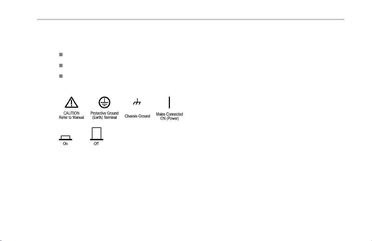
Symbols and Terms on the Product
These terms may appear on the product:
DANGER indicates an injury hazard immediately accessible as you read the marking.
WARNING indicates an injury hazard not immediately accessible as you read the marking.
CAUTION indicates a hazard to property including the product.
The following symbols may appear on the product:
General Safety Summary
DPO4000 Series User Manual vii
Page 12

Environmental Considerations
Environmental Considerations
This section provides information about the environmental impact of the prod uct.
Product End-of-Life Handling
Observe the following guidelines when recycling an instrument or compo nent:
Equipment Recycling. Production of t his equipment required the extraction and use of natural resources. The equipmen t may
contain substances that could be harmful to the environment or human health if improperly handled at the product’s end of life. In
order to avoid r elease of such substances into the environment and to reduce the use of natural resources, we encourage you to
recycle this product in an appropriate system that will ensure that most of the materials are reused or recycled appropriately.
The symbol shown below indicates that this product complies with the European Union’s requirements according to Directive
2002/96/EC on waste electrical and electronic equipment (WEEE). For information about recycling options, check the
Support/Service section of the Tektronix Web site (www.tektronix.com).
Mercury Notification. This product uses an LCD backlight lamp that contains mercury. Disposal may be regulated due
to environmental considerations. Please contact your local authorities or, within the United States, the Electronics Industries
Alliance (www.eiae.org) for disposal or recycling information.
viii DPO4000 Series User Manual
Page 13

Environmental Considerations
Restriction of Hazardous Substances
This product has been classified as Monitoring and Control equipment, and is outside the scope of the 2002/95/EC RoHS Directive.
This product is known to contain lead, cadmium, mercury, and hexavalent chromium.
DPO4000 Series User Manual ix
Page 14

Preface
Preface
This manual describes the installation and operation of the following DPO4000 Series Instruments:
DPO4104 DPO4054 DPO4034 DPO4032
Key Features
DPO4000 Series instruments can he lp you verify, debug, and characterize electronic designs. Key features include:
1 GHz, 500 MHz, and 350 MHz bandwidt hs
2 and 4 channel models
Sample rates up to 5 GS/s on all channels
10 Megapoint record length on all channels
I2C, SPI, and CAN serial triggering and analysis
(Requires use of the DPO4EMBD (for I
Wave Inspector controls for managing long record lengths, with zoom and pan, play and pause, search and mark
10.4 inch (264 mm) XGA color display
Small footprint and lightweight, at 140 mm (5.5 inches) deep and 5 kg (11 pounds)
USB and CompactFlash available for qu ick and easy storage
Built-in Ethernet port
USB 2.0 device port for direct PC control of the oscilloscope using USBTMC protocol
x DPO4000 Series User Manual
2
C and SPI) or DPO4AUTO (for CAN) application modules)
Page 15

OpenChoice documentation and an alysis software
Remote viewing with control (e*Scope and OpenChoice connectivity)
TekVPI Versatile Probe Interface supports active, differential, and current probes for automatic scaling and units
Preface
DPO4000 Series User Manual xi
Page 16

Preface
Where to Find More Information
The following information is available for your oscilloscope:
To read about Use these documents
Installation and Operation This DPO4000 User Man ual
Specifications and Performance
Verification
Programmer Commands The DPO4000 Programmer Manual (071-1845-XX) (PDF only)
Analysis and Connectivity Tools The optional Getting Started with OpenChoice Solutions Manual (02 0-2514-XX) (includes
English: 071-1785-XX
French: 071-1799-XX
Italian: 071-1800-XX
German: 071-1801 -XX
Spanish: 071-1802-XX
Japanese: 071-1803-XX
Portuguese: 071-1804-XX
Simplified Chinese: 071-1805-XX
Traditional Chinese: 071-1806-XX
Korean: 071-1807-XX
Russian: 071-1808-XX
The DPO4000 Technical Refe rence (071-1843-XX) (PDF only)
aCD)
xii DPO4000 Series User Manual
Page 17
To read about Use these docum ents
Servicing and calibration The optional DPO4000 Service Manual (071-1844-XX)
Installing and testing application
modules
The DPO4000 Series Application Module Installation Instructions manual (071-1833-XX)
(11 languages)
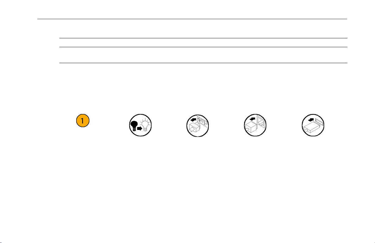
Conventions Used in This Manual
The following icons are u sed throughout this manual.
Preface
Sequence Step
DPO4000 Series User Manual xiii
Front panel power
Connect power
Network
USB
Page 18

Preface
xiv DPO4000 Series User Manual
Page 19

Installation
Before Installation
Unpack the oscilloscope and check that you received all items listed as standard accessories. The following pages list
recommended accessories and probes, instrument option s, and upgrades. Check the Tektronix Web site (www.tektronix.com) for
the most current information.
Standard Accessories
Accessory Tektronix part number
DPO4000 User Manual
English (Option L0)
French (Option L1)
Italian (Option L2)
German (Option L3)
Spanish (Option L4)
Japanese (Option L5)
Portuguese (Option L6)
Simple Chinese (Option L7)
Traditional Chinese (Option L8)
Korean (Option L9)
Russian (Option L10)
Installation
071-1785-XX
071-1799-XX
071-1800-XX
071-1801-XX
071-1802-XX
071-1803-XX
071-1804-XX
071-1805-XX
071-1806-XX
071-1807-XX
071-1808-XX
DPO4000 Series User Manual 1
Page 20

Installation
Standard Accessories (cont.)
Accessory Tektronix part number
DPO4000 Documentation Browser CD Electronic versions of DPO4000 documents,
including the Programmer M anual and the
Technical Reference.
OpenChoice Desktop CD Applications that let you capture and transfer data
from your oscilloscope to an external PC. Use the
standalone OpenChoice Desktop, MS Word, or
MS Excel Toolbars.
Calibration certificate documenting traceability
to national metrology institute(s), and ISO9001
quality system registration.
One 500 MHz, 10x passive probe per channel
Front Cover
CompactFlash memory card
Hard plastic cover to help protect the instrument 200-4908-00
Extra storage 156-9413-00
063-1810-XX
020-2514-XX
——
P6139A
2 DPO4000 Series User Manual
Page 21

Installation
Standard Accessories (cont.)
Accessory Tektronix part number
Power Cord
North America (Option A0)
Universal Euro (Option A1)
United Kingdom (Option A2)
Australia (Option A3)
Switzerland (Option A5)
Japan (Option A6)
China (Option A10)
India (Option A11)
No power cord or AC adapter (Option A99)
161-0104-00
161-0104-06
161-0104-07
161-0104-05
161-0167-00
161-A005-00
161-0306-00
161-0400-00
——
DPO4000 Series User Manual 3
Page 22

Installation
Optional Accessories
Accessory Tektronix Part Number
DPO4EMBD
The embedded serial triggering and an alysis
DPO4EMBD
module enables triggering on packet level
information on I
2
C and SPI serial buses, as w ell
as digital views of the signal, bus views, bus
decoding, search tools, and packet decode tables
with timestamp information
DPO4AUTO
The embedding automotive serial triggering and
DPO4AUTO
analysis module enables triggering on packet
level information on CAN serial buses, as well
as digital views of the signal, bus views, bus
decoding, search tools, and packet decode tables
with timestamp information
TPA-BNC TekVPI to TekProbe 2 BNC Adapter TPA-BNC
TEK-USB-488 Adapter GPIB to USB Adapter TEK-USB-488
Getting Started with OpenChoice Solutions
Manual with CD
Describes ways to develop host-computer
software applications that work with your
020-2513-XX
oscilloscope
Rackmount kit Adds rackmount brackets RM4000
Soft transit case Case for carrying instrument AC4000
Hard transit case
Traveling case, which requires use of the soft
HCTEK4321
transit case (AC4000)
4 DPO4000 Series User Manual
Page 23

Installation
Optional Accessories (cont.)
Accessory Tektronix Part Number
CompactFlash memory card
CompactFlash to USB memo ry card reader Card reader
DPO4000 Programmer Manual Describes commands for remote control of the
DPO4000 Technical Reference Manual Describes the DPO4000 oscilloscope
DPO4000 Service manual Service information
DPO4000 Module Installation Instructions
The DPO4000 oscilloscope works with multiple optional probes. (See page 10, Connecting Probes.) Check the Tektronix Web
site (www.tektronix.com) for the most current information.
Extra storage 156-9413-00
119-6827-00
071-1845-XX
DPO4000 oscilloscope. Available electronically
on the Documentation Browser CD or for
download from www.tektronix.com.
071-1809-XX
specifications and performance verification
procedure. Available electronically on the
Documentation B rowser CD or for download from
www.tektronix.com.
071-1844-XX
Manual 071-1833-XX
DPO4000 Series User Manual 5
Page 24
Installation
Operating Considerations
DPO4000 Series Oscilloscope
Input Voltage: 100 V to 240 V ±10%
Input Power Frequency:
47 Hz to 66 Hz (100 V to 240 V)
400 Hz (100 V to 132 V)
Power Consumption: 250 W maximum
Weight: 5 kg (11 lbs), stand-alone instrument
Height, including feet but not handle:
229 mm (9.0 in)
Width, from handle hub to handle hub: 439 mm
(17.3 in)
Depth, from feet to front of knobs: 137 mm
(5.4 in)
Depth, from feet to front of front cover: 145 mm
(5.7 in)
Clearance: 51 mm (2 in)
Temperature:
Operating: +0 °C to +50 °C
Nonoperating: -20 °C to +60 °C
6 DPO4000 Series User Manual
Page 25

Humidity:
Operating: High: 40 °C to 50 °C, 10% to 60% RH
Operating: Low: 0 °C to 40 °C, 10 to 90% RH
Non-operating: High: 40 °C to 60 °C, 5 to 60% RH
Non-operating: Low: 0 °C to 40 °C, 5 to 90% RH
Altitude:
Operating: 3,000 m (about 10,000 ft)
Nonoperating Altitude: 12,192 m (40,000 ft)
Random Vibration:
Operating: 0.31 G
Non-operating: 2.46 G
, 5 – 500 Hz, 10 minutes per axis, 3 axes (30 minutes total)
RMS
, 5 – 500 Hz, 10 minutes per axis, 3 axes (30 minutes total)
RMS
Pollution Degree: 2, Indoor use only
Acquisition System: 1 MΩ
The maximum input voltage at the BNC, between center conductor and shield is 400 V
deratedto2.6V
The maximum transient withstand voltage is ± 800 V
at 500 MHz.
RMS
peak
.
For steady-state sinusoidal waveforms, derate at 20 dB/decade a bove 200 kHz to 13 V
Acquisition System: 50Ω
The maximum input voltage at the BNC, between center conductor and shield is 5 V
RMS
(DF ≤ 39.2%), 250 V
peak
at 3 MHz and above.
pk
to 130 kHz
RMS
, with peaks ≤ ±20 V (DF ≤ 6.25%)
Installation
DPO4000 Series User Manual 7
Page 26

Installation
External Trigger: 1 MΩ
The maximum input voltage at the BNC, between center conductor and shield is 400 V
derated to 5 V
The maximum transient withstand voltage is ±800 V
at 500 MHz.
RMS
peak
.
For steady-state sinosoidal waveforms, derate at 20 dB/decade above 200 kHz to 13 V
P6139A Passive Probe
Input Voltage:
400 V
300 V
150 V
For steady-state, sinusoidal waveforms, derate at 20 dB/decade above 2.5 MHz to 50 V
Output Voltage (terminated into 1 MΩ):
40 V
30 V
15 V
Temperature:
Operating: -15 °C to +65 °C ( +5 °F to +149 °F )
Nonoperating: -62 °C to +85 °C ( -80 °F to +185 °F)
or 400 V DC; CAT I (2,500 V
RMS
or 300 V DC; CAT II (2,500 V
RMS
or 150 V DC; CAT III (2,500 V
RMS
or 40 V DC; CAT I (2,500 V
RMS
or 30 V DC; CAT I (250 V
RMS
or 15 V DC; CAT I (250 V
RMS
peak
peak
peak
transient)
peak
transient
peak
transient)
peak
impulse)
impulse)
impulse)
(DF ≤ 39.2%), 250 V
peak
at 3 MHz and above.
peak
at 20 MHz and above.
RMS
to2MHz
RMS
Altitude: ≤ 2,000 meters
8 DPO4000 Series User Manual
Page 27

Installation
Pollution Degree: 2, Indoor use only
Humidity:
Operating: High: 40 °C to 50 °C, 10% to 60% RH
Operating: Low: 0 °C to 40 °C, 10 to 90% RH
CAUTION. To ensure proper cooling, keep the sides and rear of the instrument clear of obstructions.
Cleaning
Inspect the oscilloscope and pro bes as often as operating conditions require. To clean the exterior surface, perform the following
steps:
1. Remove loose dust on the outside of the oscilloscope and probes with a lint-free cloth. Use care to avoid scratching the clear
glass display filter.
2. Use a soft cloth dampened with water to clean the oscilloscope. Use an aqueous solution of 75% isopropyl alcohol for
more efficient cleaning.
CAUTION. To avoid damage to the surface of the oscilloscope or probes, do not use any abrasive or chemical cleaning agents.
DPO4000 Series User Manual 9
Page 28
Installation
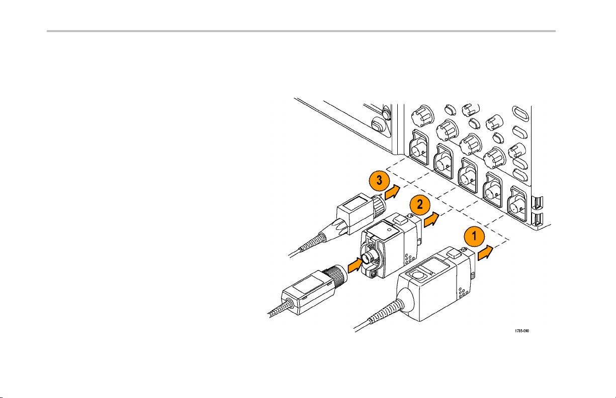
Connecting Probes
The DPO4000 oscilloscope supports probes with the following:
1. Tektronix Versatile Probe Interf ace
(TekVPI)
These probes support two-way
communication with the oscilloscope
through on-screen menus and remotely
through programmable support. The
remote control is usefu l in applications like
ATE where you want the system to preset
probe parameters.
2. TPA-BNC Adapter
The TPA-BNC Adapter allows you to use
TekProbe Level II probe capabilities, such
as providing probe power and passing
information to the oscilloscope on scaling
and whether the units are volts or amperes.
3. Plain BNC interfaces
These probes only pass the waveform
signal to the oscilloscope. There is no
other communication.
10 DPO4000 Series User Manual
Page 29

For more information on the many probes available for use with DPO4000 oscilloscopes, refer to www.tektronix.com.
Powering On the Oscilloscope
Ground the Oscilloscope and Yourself
Before pushing the power switch, connect the oscilloscope to an electrically neutral reference point, such as earth ground. Do this
by plugging the three-pronged power cord into an outlet grounded to earth ground.
Grounding the oscilloscope is necessary for safety and to take accurate measurements. The oscilloscope needs to share the
same ground as any circuits that you are testing.
Installation
DPO4000 Series User Manual 11
Page 30

Installation
If you are working with static sensitive
components, ground yourself. Static electricity
that builds up on your body can da mage
static-sensitive components. Wearing a
grounding strap safely sends static charges on
your body to earth ground.
12 DPO4000 Series User Manual
Page 31

To connect the power cord and power on the oscilloscope:
Installation
DPO4000 Series User Manual 13
Page 32

Installation
Powering Off the Oscilloscope
To power off the oscilloscope and remove the power cord:
14 DPO4000 Series User Manual
Page 33

Functional Check
Perform this quick functional check to verify that your oscilloscope is operating correctly.
1. Connect the oscilloscope power cable as
described above.
2. Power on the oscilloscope.
Installation
DPO4000 Series User Manual 15
Page 34

Installation
3. Connect the oscilloscope P6139A probe tip
and reference lead to the PROBE COMP
connectors.
4. Press Default Setup.
16 DPO4000 Series User Manual
Page 35

5. Push the Autoset button. The screen
should now display a square wave,
approximately 2.5 V at 1 kHz.
If the signal appears but is misshapen,
perform the procedures for compensating
the probe. (See page 17, Compensating
the Probe.)
If no signal appears, rerun the procedure.
If it no signal still appears, have the
instrument serviced by qualified service
personnel.
Compensating the Probe
Whenever you attach a passive voltage probe for the first time to any input channel, compensate the probe to match it to
the corresponding oscilloscope input channel.
To properly compensate y our passive probe:
1. Follow the steps for the functional check.
(See page 15, Functional Check.)
Installation
DPO4000 Series User Manual 17
Page 36

Installation
2. Check the shape of the displayed
waveform to determine if your probe is
properly compensated.
3. If necessary, adjust your probe. Repeat
as needed.
Properly compensated
Under compensated Over compensated
18 DPO4000 Series User Manual
Page 37

Quick Tips
Use the shortest possible ground lead and signal
path to minimize probe-induced ringing and
distortion on the measured signal.
Installation
Short ground lead
Long ground lead
Installing an Application Module
CAUTION. To avoid damage to the oscilloscope or application module, observe ESD precautions. (See page 11, Powering
On the Oscilloscope.)
Turn off the oscilloscope power while removing or ad ding an application module.
(See page 14, Powering Off the Oscilloscope.)
DPO4000 Series User Manual 19
Page 38

Installation
Optional application module packages extend the capability of your oscilloscope. Install up to four application modules at one
time into the two slots with windows in the upper right corner of the front panel and the two additional slots hidden behind the two
you can see.
Refer to the DPO4000 Series Application Module Installation Instructions that came with your application module for instructions
on installing and testing an application module.
NOTE. If you remove an application module, the features provided by the application module become unavailable. To restore the
features, turn off th e oscilloscope powe r, reinstall the module and turn on the oscilloscope power.
Changing the User Interface Language
To change the language of the oscilloscope user interface and the front-panel button labels:
1. Push Utility.
2. Push System repeatedly until you select
Config from the pop-up menu.
20 DPO4000 Series User Manual
Config
Page 39

Installation
3. Push Language from the resulting lower-bezel
menu.
4. Push the side-bezel button corresponding
to the desired language. Ch oose among:
English, French, Italian, German, Spanish,
Japanese, Brazilian Portuguese, Simplified
Chinese, Traditional Chinese, Korean, and
Russian.
System
Config
Language
English
Francais
Deutsch
Italiano
-more1of3
Language
English
Set Date &
Time
TekSecure
Erase
Memory
Version
v1.00
DPO4000 Series User Manual 21
Page 40

Installation
5. If you choose to use English, be sure that the
plastic front-panel overlay is removed.
If you choose a language other than English,
place the plastic overlay for the language
that you desire over the front panel to display
labels in that language.
22 DPO4000 Series User Manual
Page 41

Changing the Date and Time
To set the internal clock with the current date and time:
1. Push Utility.
Installation
2. Push System repeatedly until you select
Config
Config from the pop-up menu.
3. Push Set Date & Time.
System
Config
Language
English
Set Date &
Time
TekSecure
Erase
Memory
Version
DPO4000 Series User Manual 23
Page 42

Installation
4. Push the side-panel buttons and rotate both
multipurpose knobs (a and b)tosetthetime
and date values.
5. Push OK Enter Date & Time.
Date Time
Set
Display
Date/Time
ON OFF
Hour: 4
Min: 1
Month: July
Day: 19
Year: 2005
OK Enter
Date &
Time
OK Enter
Date &
Time
24 DPO4000 Series User Manual
Page 43

Signal Path Compensation
Signal Path Compensation (SPC) corrects for DC inaccuracies caused by temperature variations and/or long-term drift. Run the
compensation whenever the ambient temperature has changed by more tha n 10 °C or once a week if you use vertical settings of
5 mV/division or less. Failure to do so may result in the instrument not meeting warranted performance levels at those volts/div
settings.
To compensate the signal path:
1. Warm up the oscilloscope for at least
20 minutes. Remove all input signals (probes
and cables) f rom channel inputs. Input signals
with AC components adversely affect SPC.
Installation
DPO4000 Series User Manual 25
Page 44

Installation
2. Push Utility.
3. Push System repeatedly until you select
Calibration
Calibration from the resulting pop-up menu.
4. Push Signal Path from the lower-bezel menu.
5. Push OK Compensate Signal path from the
resulting side-bezel menu.
System
Calibration
OK Com-
pensate
Signal Path
Signal Path
Pass
Factory
Pass
The calibration will take approximately
10 minutes to complete.
26 DPO4000 Series User Manual
Page 45

Installation
6. After calibration, verify that the status indicator
on the lower-bezel menu displays Pass.
System
Calibration
Signal Path
Pass
Factory
Pass
If it does not, then recalibrate the instrument
or have the instrument serviced by quali fi ed
service personnel.
7. Service personnel use the factory calibration
functions to calibrate the internal voltage
references of the oscilloscope using external
sources. Refer to your Tektronix field office
or representative for assistance with factory
calibration.
NOTE. Signal Path Compensation does not include calibration to the probe tip. (See page 17, Compensa ting the Probe.)
DPO4000 Series User Manual 27
Page 46

Installation
Upgrading Firmware
To upgrade the firmware of the oscilloscope:
1. Open up a Web browser and go to
www.tektronix.com. Proceed to the softw are
finder. Download the latest firmware for your
DPO4000 series oscilloscope on to a USB
storage device.
28 DPO4000 Series User Manual
Page 47

2. Power off your DPO4000.
Installation
DPO4000 Series User Manual 29
Page 48

Installation
3. Insert the USB stora ge device into the
front-panel USB port on your DPO4000.
30 DPO4000 Series User Manual
Page 49

4. Power on the DPO4000 . The instrument
automatically recognizes the replacement
firmware and installs it.
If the instrument does not install the firmware,
rerun the procedure. It the problem continues,
contact qualified service personnel.
CAUTION. Do not power off the oscilloscope
or remove the USB storage device until the
oscilloscope finishes installing the firmwar e.
Installation
DPO4000 Series User Manual 31
Page 50

Installation
5. Power off the DPO4000 and remove the USB
storage device.
32 DPO4000 Series User Manual
Page 51

6. Power on the DPO4000.
7. Push Utility.
Installation
DPO4000 Series User Manual 33
Page 52

Installation
8. Push Version. The oscilloscope displays the
firmware version number.
System
Config
9. Confirm that the version number matches that
of the new firmware.
Connecting Your Oscilloscope to a Computer
You may want to document your work for future reference. Instead of saving screen images and waveform data to a CompactFlash
or USB storage device, and then generating a report later, you may want to send it directly to a remote PC for analysis. You may
also want to control an oscilloscope at a remote location from your comp uter.
Two ways to connect your oscilloscope to a computer are the TekVISA-based OpenChoice and the e*Scope Web-enabled tool.
Use OpenChoice to communicate with your oscilloscope from your co mputer through a software application. Use e*Scope to
communicate with your oscilloscope through a Web browser.
Using OpenChoice
OpenChoice lets you use your MS-Windows computer to acquire data from your oscilloscope for use in an analysis package that
runs on your PC, such as Microsoft Excel, National Instruments Lab VIEW. or a program of your own creation. You can use a
common communications protocol, such as USB, Ethernet, or GPIB to connect the computer to the oscilloscope.
Language
English
Set Date &
Time
TekSecure
Erase
Memory
Version
34 DPO4000 Series User Manual
Page 53

To set up OpenChoice communications between your oscilloscope and a computer:
1. Load the TekVISA drivers on your comp uter.
Find these on the OpenChoice D esktop
CD or at the Tektronix software finder Web
page (www.tektronix.com). When done, the
TekVISA icon appears in the Windows System
Tray. Typically, this is the bottom right of
the Windows desktop on your MS-Windo ws
computer.
Installation
DPO4000 Series User Manual 35
Page 54

Installation
2. Connect the DPO4000 to your computer with
the appropriate USB or Ethernet cable.
To communicate between the DPO4000 and a
GPIB system, connect the oscilloscope to the
TEK-USB-488 GPIB-to-USB Adapter with a
USB cable. Then connect the adapter to your
GPIB system with a GPIB cable.
36 DPO4000 Series User Manual
Page 55

3. Push Utility.
Installation
4. Push System repeatedly to select I/O.
5. To use Ethernet, push Ethernet Network
Settings.
I/O
System
I/O
USB
Enabled
Ethernet
Network
Settings
GPIB
1
DPO4000 Series User Manual 37
Page 56

Installation
On the side-bezel menu, if you are on a DHCP
Ethernet network and using a through cable,
set DHCP to On. If you are using a cross-over
cable, set it to Off and set a hard coded TCPIP
address.
6. If you are using GPIB , pu sh GPIB.
7. Enter the GPIB address on the side-bezel
menu, using multipurpose knob a.
This will set the GPIB address on an attached
TEK-USB-488 Adapter.
Network
Configura-
tion
Change
Instrument
Settings
DHCP/
BOOTP
On
Off
Test
Connection
Talk/Listen
Address
a
1
38 DPO4000 Series User Manual
Page 57

8. If you are using USB, the system sets itself up
automatically for you, if USB is enabled.
Check USB on the bottom-bezel menu to
be sure that USB is enabled. If it is not
enabled, push USB.ThenpushEnabled on
the side-bezel menu.
9. Run your application soft ware on your
computer.
10. In case of pro blems getting oscilloscope-to-PC
communications to work, refer to the
networking troubleshooter. To bring up the
troubleshooter, click the TekVISA icon on the
System Tray of your MS-Wind ows computer.
Then go to the online help.
Quick Tips
The DPO4000 comes with a va riety of Windows-based software tools designed to ensure efficient connectivity between your
oscilloscope and your computer. There are tool bars that speed connectivity with Microsoft Excel and Word. There is also a
standalone acquisition program called the OpenChoice Desktop.
The rear-panel USB 2.0 device port is the correct USB port for computer connectivity. Use the rear- and front-panel USB 2.0
host ports to connect your oscilloscope to storage devices and printers.
Installation
DPO4000 Series User Manual 39
Page 58

Installation
Using e*Scope
e*Scope lets you access any Internet-connected DPO4000 Series Oscilloscope from a browser on your workstation, PC, or laptop
computer. N o matter where you are, your DPO4000 is as close as the nearest browser.
To set up e*Scop e communications between your oscilloscope and a Web browser running on a remote computer:
1. Connect the DPO4000 to your computer
network with the appropriate Ethernet cable.
2. Push Utility.
40 DPO4000 Series User Manual
Page 59

Installation
3. Push System repeatedly to select I/O.
4. Push Ethernet Network Settings.
I/O
System
I/O
USB
Ethernet
Network
Settings
GPIB
DPO4000 Series User Manual 41
Page 60

Installation
5. Push Change Instrument Settings to
determine the Ethernet address and
instrument name.
On the side-bezel menu, if yo u are on a
DHCP Ethernet network and using dynamic
addressing, set DHCP to On. If you are using
static addressing, set it to Off.
6. Start your browser on your remote computer.
In the browser address line, enter the IP
address or, if DHCP is set to On in the
oscilloscope, simply enter the instrument
name.
Network
Configura-
tion
Change
Instrument
Settings
DHCP/
BOOTP
On Off
Test
Connection
42 DPO4000 Series User Manual
Page 61

7. You should now see the e*Scope screen, with
a copy of the oscilloscope display, on your
Web browser.
If e*Scope does not work, rerun the proce dure.
If it still does not work, contact qualified service
personnel.
Installation
DPO4000 Series User Manual 43
Page 62

Installation
44 DPO4000 Series User Manual
Page 63

Get Acquainted with the Instrument
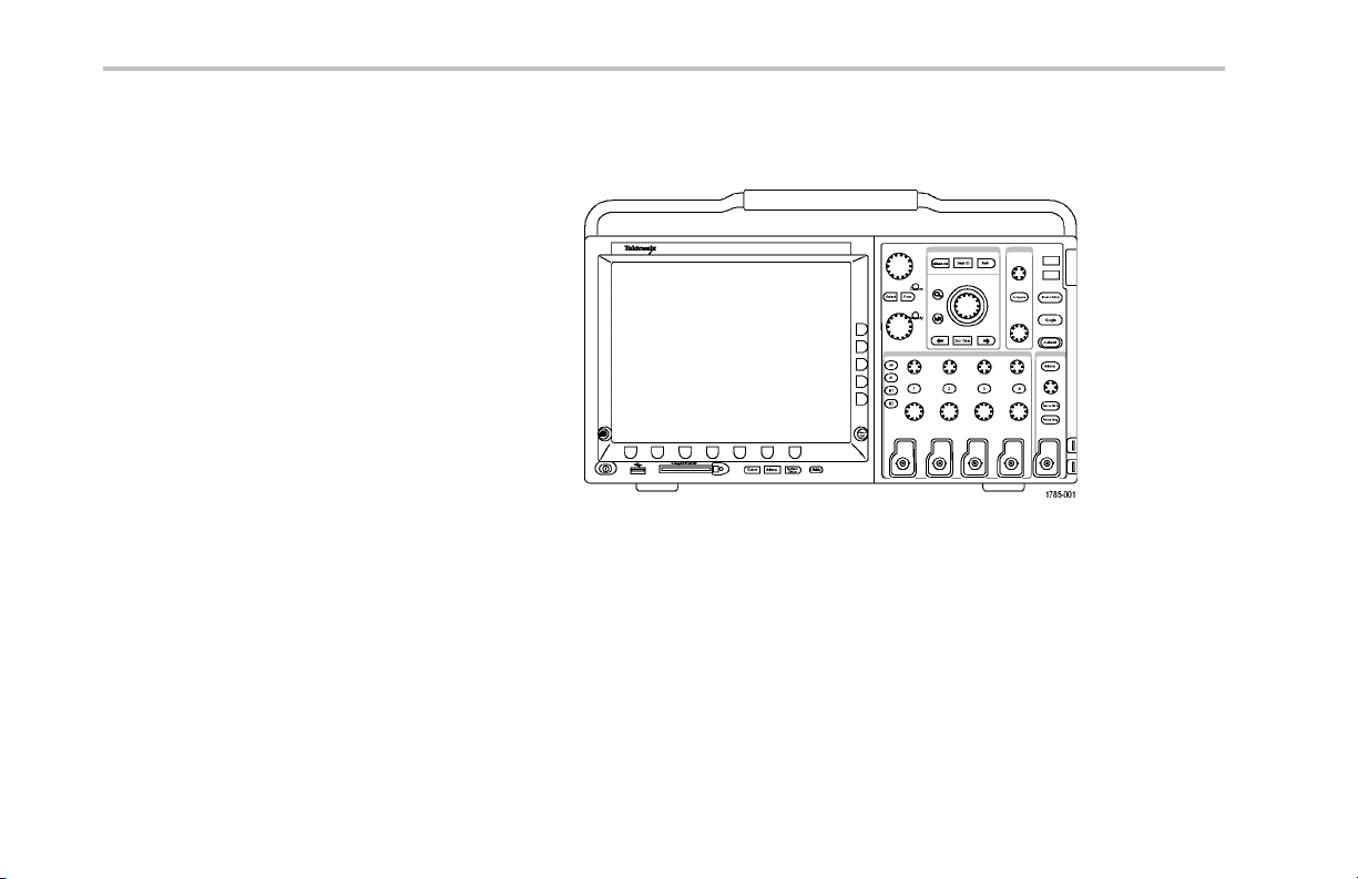
Front-Panel Menus and Controls
The front panel has buttons and controls for the functions that you use most often. Use the menu buttons to access more
specialized functions.
Get Acquainted with the Instrument
DPO4000 Series User Manual 45
Page 64

Get Acquainted with the Instrument
Using the Menu System
To use the menu system:
1. Push a front-panel menu button to display
the menu that you want to use.
46 DPO4000 Series User Manual
Page 65

2. Push a lower-bezel button to select a menu
item. If a pop-up menu appears, push the
lower-bezel button repeatedly to select the
desired choice.
3. Push a side-bezel button to choose a
side-bezel menu item.
If the menu item contains more than
one choice, push the side-bezel button
repeatedly to cycle through the choices.
Get Acquainted with the Instrument
DPO4000 Series User Manual 47
Page 66

Get Acquainted with the Instrument
4. To remove a side-bezel menu, push the
lower-bezel button again or push Menu
Off.
5. Certain menu choices require you to set
a numerical value to complete the setup.
Use the upper and lower multipurpose
knobs a and b to adjust values.
6. Push Fine to turn off or on the ability to
make smaller adjustments.
48 DPO4000 Series User Manual
Page 67

Using the Menu Buttons
Use the menu buttons to perform many functions in the oscilloscope.
1. Measure. Push to perform automated
measurements on waveforms or to
configure cursors.
2. Search. Push to search through an
acquisition for user-d e fined events/criteria.
3. Test. Push to activate advanced or
application-specific testing features.
4. Acquire. Push to set the acquisition mode
and adjust the record length.
5. Autoset. Push to perform an automatic
setup of oscilloscope settings.
6. Trigger Menu. Push to specify trigger
settings.
Get Acquainted with the Instrument
DPO4000 Series User Manual 49
Page 68

Get Acquainted with the Instrument
7. Utility. Push to activate the system utility
functions, such as selecting a language or
setting the date/time.
8. Default Setup. Push to restore the
oscilloscope to the default s e ttings.
9. Save / Recall Menu . Pushtosave
and recall setups, waveforms, and
screen images to internal memory, a
CompactFlash card, or a USB storage
device.
10. Channel 1,2,3,or4. Push to set vertical
parameters for input waveforms and to
display or remove the corresponding
waveform from the display.
50 DPO4000 Series User Manual
Page 69

11. B1 or B2. Pushtodefine and display a
bus, if you have the appropriate module
application keys. The DPO4AUTO module
supports CAN. The DPO4EMBD module
supports I
2
C and SPI.
Also, push the B1 or B2 button to display
or remove the corresponding bus from the
display.
12. R. Push to manage reference waveforms,
including the display or removal of each
reference waveform from the display.
13. M. Push to manage the math waveform,
including the display or removal of the
math waveform from the display.
Get Acquainted with the Instrument
DPO4000 Series User Manual 51
Page 70

Get Acquainted with the Instrument
Using Other Controls
These buttons and knobs control waveforms, cursors and other data input.
1. Turn the upper multipurpose knob a,
when activated, to move a cursor or set
a numerical parameter value for a menu
item. Push the nearby Fine button to toggle
between coarse and fine adjustment.
Screen icons tell you when a or b are
active.
2. Cursors. Push once to activate the two
vertical cursors. Push again to turn on the
two vertical and two horizontal cursors.
Push again to turn off all cursors.
When the cursors are on, you can turn
the multipurpose knobs to control their
position.
52 DPO4000 Series User Manual
Page 71

3. Select. Push to activate special functions.
For example, when using the two vertical
cursors (and no horizontal one s are
visible), you can push this button to link or
unlink the cursors. When the two vertical
and two horizonta l cursors are both visible,
you can push this button to make either
the vertical cursors or the horizontal ones
active.
4. Fine. Push to toggle between making
coarse and fine adjustments with the
vertical and horizontal position knobs, the
trigger level knob, and many operations of
multipurpose knobs a and b.
5. Waveform Intensity. Push to enable
multipurpose knob a to control waveform
display intensity and knob b to control
graticule intensity.
Get Acquainted with the Instrument
DPO4000 Series User Manual 53
Page 72

Get Acquainted with the Instrument
6. Turn the lower multipurpose knob b,
when activated, to move a cursor or set
a numerical parameter value for a menu
item. Push Fine to make adjustments
more slowly.
7. Zoom button. Push to activate zoom mode.
8. Pan (outer knob). Turn to scroll the zoom
window through the acquired waveform.
9. Zoom (inner knob). Turn to control the
zoom factor. Turning it clockwise zooms in
further. Turning it counterclockwise zooms
out.
10. Play-pause button. Push to start or stop the
automatic panning of a waveform. Control
the speed and direction with the pan knob.
11. ← Prev. Push to jump to the previous
waveform mark.
54 DPO4000 Series User Manual
Page 73

12. Set/C lear Mark. Push to establish or
delete a waveform mark.
13. → Next. Pushtojumptothenext
waveform mark.
14. Horizontal Position. Turn to adjust
the trigger point location relative to the
acquired waveforms. Push Fine to make
smaller adjustments.
15. Horizontal Scale. Turn to adjust the
horizontal scale (time/division).
Get Acquainted with the Instrument
DPO4000 Series User Manual 55
Page 74

Get Acquainted with the Instrument
16. Run/Stop. Pushtostartorstop
acquisitions.
17. Single. Push to make a single acquisition.
18. Autoset. Push to automatically set the
vertical, horizontal, and trigger controls for
a usable, stable display.
19. Trigger Level. Turn to adjust the trigger
level.
20. Set to 50%. Push to set the trigger level to
the midpoint of the waveform.
21. Force Trig. Push to force an immediate
trigger event.
56 DPO4000 Series User Manual
Page 75

22. Vertical Position. Turn to adjust the
vertical position of the corresponding
waveform. Push Fine to make sma ller
adjustments.
23. 1,2,3,4. Push to display or remove the
corresponding waveform from the display
and access the vertical menu.
24. Vertical Scale. Turn to adjust the vertical
scale factor of the corresponding waveform
(volts/division).
25. Print. Push to initiate a hard copy using the
printer selected in the Utility menu .
26. Power switch. Push to power on or off the
instrument.
Get Acquainted with the Instrument
DPO4000 Series User Manual 57
Page 76

Get Acquainted with the Instrument
27. USB 2.0 host port. Insert a USB cable here
to connect peripherals, such as printers
and storage devices, to the oscilloscope.
There are also two more USB 2.0 host
ports on the rear panel.
28. CompactFlash Drive. Insert a
CompactFlash card here.
29. CompactFlash Eject. Pops the
CompactFlash card out of the
CompactFlash drive.
30. Save. Push to perform an immediate save
operation. The save operation uses the
current save parameters, as definedinthe
Save / Recall menu.
31. Default Setup. Push to perform an
immediate restore of the oscilloscope to
the default settings.
32. Menu Off. Push to clear a d isplayed menu
from the screen.
58 DPO4000 Series User Manual
Page 77

Identifying Items in the Display
The items shown to the right may a ppear in the
display. Not all o f these items are visible at any
given time. Some readouts move outside the
graticule area when me nus are turned off.
Get Acquainted with the Instrument
DPO4000 Series User Manual 59
Page 78

Get Acquainted with the Instrument
1. The acquisition readout shows when an
acquisition is running, stopped, or when
acquisition preview is in effect. Icons are:
Run: Acquisitions enabled
Stop: Acquisitions not enabled
Roll: In roll mode (40 ms/div or slower)
PreVu: In this state, the oscilloscope
is stopped or between triggers. You
can change the horizontal or vertical
position or scale to see approximat ely
what the next acquisition will look like.
RUN
60 DPO4000 Series User Manual
Page 79

2. The trigger position icon shows the trigger
position in the acquisition.
3. The expansion point icon (an orange
triangle) sho ws the point that the horizontal
scale expands and compre sse s around.
4. The waveform record view shows the
trigger location relative to the waveform
record. The line color corresponds to the
selected waveform color.
Get Acquainted with the Instrument
DPO4000 Series User Manual 61
Page 80

Get Acquainted with the Instrument
5. The trigger status readout shows trigger
status. Status conditions are:
Trig’d: Triggered
Auto: Acquiring untriggered signal
PrTrig: Acquiring pretrigger data
Trig?: Waiting for trigger
6. The cursor readout shows time, amplitude,
and delta (∆) values for each cursor.
For FFT measurements, it shows frequency
and magnitude.
Trig’d
62 DPO4000 Series User Manual
Page 81

7. The trigger level icon sho ws the trigger
level on the waveform. The icon color
corresponds to the trigger source channel
color.
8. The edge trigger readout shows the trigger
source, slope, and level. The trigger
readouts for other trigger types show other
parameters.
9. The top line of the record length/sampling
rate readout shows the sampling rate
(adjust with the Horizontal Scale knob).
The bottom line shows the record length
(adjust with the Acquire menu).
Get Acquainted with the Instrument
DPO4000 Series User Manual 63
Page 82

Get Acquainted with the Instrument
10. The horizontal position/ scale readout
shows on the top line the horizontal scale
(adjust with the Horizontal Scale knob)
and on the bottom line the time from the T
symbol to the expansion point icon (adjust
with the Horizontal Position knob).
Use horizontal position to insert added
delay between when the trigger occurs and
when you actually capture the data. I nsert
a negative time to capture more pretrigger
information.
11. The auxiliary waveform readouts show the
vertical and horizontal scale factors of the
math or reference waveforms.
12. The channel readout shows the channel
scale factor (per division), coupling, and
invert status. Adjust with the Vertical Scale
knob and th e channel 1, 2, 3,or4 menus.
64 DPO4000 Series User Manual
Page 83

13. Measurement readouts show the selected
measurements. You can select up to four
measurements to display at one time.
A
symbol appears instead of the
expected numerical measurement if a
vertical clipping condition exists. Part of the
waveform is above or below the display. To
obtain a proper numerical measurement,
turn the vertical scale and position knobs
to make all of the waveform appear in the
display.
14. The waveform baseline indicator shows
the zero-volt level of a waveform (ignoring
the effect of offset). The icon colors
correspond to the waveform colors.
Get Acquainted with the Instrument
DPO4000 Series User Manual 65
Page 84

Get Acquainted with the Instrument
Front-Panel Connectors
1. Channel 1, 2,(3, 4). Channel inputs with
TekVPI Versatile Probe Interface.
2. Aux In. Trigger level range is adjustable
from +8 V to –8 V. The maximum input
voltage is 400V peak, 250V RMS. Input
resistance is 1 MΩ ± 1% in parallel with
13 pF ±2 pF.
3. PROBE COMP. Sq uare wave signal
source to compen sate probes. Output
voltage: 0 – 2.5V, amplitude ± 1% behind
1k Ω ±2%. Frequency: 1 kHz.
4. Ground .
5. Application Module Slots.
66 DPO4000 Series User Manual
Page 85

Side-Panel Connector
1. Ground strap connector. This is a
receptacle for a grounding strap.
Get Acquainted with the Instrument
DPO4000 Series User Manual 67
Page 86

Get Acquainted with the Instrument
Rear-Panel Connectors
1. Trigger Out. Use the trigger signal output
to synchronize other test equipment
with your oscilloscope. A LOW to H IGH
transition indicates the trigge r occurred.
The logic level for Vout (HI) is ≥2.5V open
circuit; ≥1.0 V into a 50Ω load to ground.
The logic level f or Vout (LO) is ≤0.7 V into
a load of ≤4mA;≤0.25 V into a 50Ω load
to ground.
2. XGA Out. UsetheXGAVideoport(DB-15
female connector) to show the oscilloscope
display on an external monitor or projector.
3. LAN. Use the LAN (Ethernet) port (RJ-45
connector) to connect the oscilloscope to a
10/100 Base-T local area network.
4. Device. Use the USB 2.0 High speed
device port to control the oscilloscope
through USBTMC or GPIB with a
TEK-USB-488 Adapter. The USBTMC
protocol allows USB devices to
communicate using IEEE488 style
messages. This lets you run your GPIB
software applications on USB hardware.
68 DPO4000 Series User Manual
Page 87

5. Host. Use the USB 2.0 Full speed host
ports (two) to take advantage of USB mass
storage devices and printers.
6. Power input. Attach to an AC power line
with integral safety ground. (See page 6,
Operating Considerations.)
Get Acquainted with the Instrument
DPO4000 Series User Manual 69
Page 88

Acquire the Signal
Acquire the Signal
This section describes concepts of and procedures for setting up the oscilloscope to acquire the signal as you want it to.
Setting Up Signal Input
Use front-panel buttons to set up your instrument to acquire the signal.
1. Connect the P6139A or VPI probe to the
input signal source.
70 DPO4000 Series User Manual
Page 89

2. Select the input channel by pushing the
front-panel buttons.
NOTE. If you are using a probe that does not
supply probe encoding (not a P6139A nor a
VPI probe), set the attenuation (probe factor)
on the oscilloscope side-bezel menu.
3. Push Autoset.
Acquire the Signal
DPO4000 Series User Manual 71
Page 90

Acquire the Signal
4. Push the desired channel butto n. Then
adjust the vertical position and scale.
5. Adjust the horizontal position and scale.
The horizontal p osition determines the
number of pretrigger and posttrigger
samples.
The horizontal scale determines the size
of the acquisition window relative to the
waveform. You can scale the window to
contain a waveform edge, a cycle, several
cycles, or thousands of cycles.
72 DPO4000 Series User Manual
Page 91

Quick Tip
Use the zoom feature to see multiple acquisition cycles in the upper part and a single cycle in the lower part of the display.
(See page 163, Managing Long Record Length Waveforms.)
Using the Default Setup
To return the oscilloscope to its default settings:
1. Push Default Setup.
Acquire the Signal
2. If you change your mind, push Undo Default
Setup to undo the last default setup.
Undo
Default
Setup
Quick Tip
The DPO4000 Technical Reference describes the default setup settings in detail. This manual is available on the accompanying
CD or at www.tektronix.com.
DPO4000 Series User Manual 73
Page 92

Acquire the Signal
Using Autoset
Autoset adjusts the instrument (acquisition, horizontal, trigger, and vertical controls) such that it displays two or three waveform
cycles with the trigger near the midlevel.
1. Connect the probe, and then select the input
channel. (See page 70, Setting Up Signal
Input.)
2. Push Autoset to execute an Autoset.
3. If desired, push Autoset Undo to undo the
last Autoset.
74 DPO4000 Series User Manual
Undo
Autoset
Page 93

Quick Tips
To position the waveform appropriately, Autoset may change the vertical position. Autoset always sets vertical offset to 0 V.
If you use Autoset w hen no channels are displayed, the instrument turns on channel one (1) and scales it.
Acquisition Concepts
Before a signal can be displayed, it must pass through the input channel where it is scaled and digitize d. Each channel has a
dedicated input amplifier and digitizer. Each channel produces a stre am of digital data from w hich the instrument extracts waveform
records.
Sampling Process
Acquisition is the process of sampling an
analog signal, converting it into digital data,
and assembling it into a waveform record,
which is then stored in acquisition memory.
Input signal
Acquire the Signal
Sampled points
Digital values
DPO4000 Series User Manual 75
Page 94

Acquire the Signal
Real-time Sampling
DPO4000 series oscilloscopes use real-time
sampling. In real-time sampling, the instrument
digitizes all of the points it acquires using a
single trigger event.
Record points
Sampling rate
76 DPO4000 Series User Manual
Page 95

Waveform R ecord
The instrument builds the waveform record through use of the following parameters:
Sample interval: The time between
recorded sample points. Adjust this by
turning the Horizontal Scale knob.
Record length: The numb er of samples
required to fill a wa veform record. Set this
by pushing the Acquire button and using
the resulting lower-bezel menu.
Trigger point: The zero time reference in a
waveform record. It is shown on the screen
by an orange T.
Acquire the Signal
DPO4000 Series User Manual 77
Page 96

Acquire the Signal
Horizontal position: The time from the
trigger point to the expansion point. Adjust
this by turning the Horizontal Position
knob.
Use a positive time to acquire the record
after the trigger point. Use a negative time
to acquire it before the trigger point.
Expansion point: The point that the
horizontal scale expands and contracts
around. It is shown by an orange triangle.
How the Acquisition Modes Work
Sample mode retains the first sampled point
from each acquisition interval. Sample is the
default mode.
78 DPO4000 Series User Manual
Page 97

Peak Detect mode uses the highest and lowest
of all the samples contained in two consecutive
acquisition intervals. This mode only works
with real-time, noninterpolated sampling and is
useful for catching high frequency glitches.
Hi Res mode calculates the average of all
the samples for each acquisition interval.
This mode also only works with real-time,
noninterpolated sampling. Hi-Res provides a
higher-resolution, lower-bandwidth waveform.
Envelope mode finds the highest and
lowest record points over all acquisitions.
Envelope uses Peak Detect for each individual
acquisition.
Average mode calculates the average value for
each record point over a user-specified number
of acquisitions. Average uses Sample mode for
each individual acquisition. Use average mode
to reduce random noise.
Acquire the Signal
DPO4000 Series User Manual 79
Page 98

Acquire the Signal
Changing the Acquisition Mode and Record Length
Use this procedure to change the acquisition mode.
1. Push Acquire.
2. Push Mode.
Mode
Average
Record
Length
10k
Reset
Horizontal
Position
Waveform
Display
80 DPO4000 Series User Manual
Page 99

Acquire the Signal
3. Then choose the acquisition mode from
the side-bezel menu. You can chose from:
Sample, Peak Detect, Hi Res, Envelope, or
Average.
NOTE. Peak Detect and High Res require more
than one sample point per sample interval. If there
is only one sample point, these two mode s will
appear the same as sample mode.
Acquisition
Mode
Sample
Peak
Detect
Hi Res
Envelope
Average
16
DPO4000 Series User Manual 81
Page 100

Acquire the Signal
4. If you chose Average, turn multipurpose knob
a to set the number of waveforms to average
over.
5. Push Record Length.
6. Push the side-bezel menu, record length
1000 points
button.
Choose between: 1000, 10 k, 100 k, 1 M, and
10 M points.
82 DPO4000 Series User Manual
 Loading...