

Page 1

xx
MSO2000B, DPO2000B, MSO2000 and DPO2000
ZZZ
Series Oscilloscopes
Programmer Manual
*P077073800*
077-0738-00
Page 2

Page 3

xx
MSO2000B, DPO2000B, MSO2000 and DPO2000
ZZZ
Series Oscilloscopes
Programmer Manual
Revision A
www.tektronix.com
077-0738-00
Page 4

Copyright © Tektronix. All rights reserved. Licensed software products are owned by Tektronix or its subsidiaries
or suppliers, and are protected by national copyright laws and international treaty provisions.
Tektronix products are covered by U.S. and foreign patents, issued and pending. Information in this publication
supersedes that in all previously published material. Specifications and price change privileges reserved.
TEKTRONIX and TEK are registered trademarks of Tektronix, Inc.
Contacting
Tektronix, Inc.
14150 SW Karl Braun Drive
P.O. B o x 5 0
Beaverton, OR 97077
USA
For product information, sales, service, and technical support:
In North America, call 1-800-833-9200.
Worl dwi
Tektronix
0
de, visit www.tektronix.com to find contacts in your area.
Page 5

Table of Contents
Getting Started ..... . ..... . ..... . ... . . ..... . ..... . ..... . ..... . ..... . ... . . . .... . ..... . ..... . ..... . ..... . ..... . ..... . 1-1
Setting Up Remote Communications Hardware . . .... . ..... . ..... . ... . . ..... . ..... . ... . . . .... . ..... . .... 1-2
Connecting via Ethernet................................................................................ 1-2
Connecting via USB........... ................................ .................................. ....... 1-3
Connecting via GPIB ...................... ................................ ............................. 1-4
Setting Up Remote Communications Software . ..... . ..... . ... . . . .... . ..... . ..... . ..... . ... . . ..... . ..... 1-5
Using TekVISA .......................... ................................ ............................... 1-6
Using Tektronix e*Scope Software .................................................................. 1-7
Documentation ............................................................................................... 1-9
Command Syntax...................................... .................................. ......................... 2-1
Command and Query Structure ............................................................................ 2-1
Clearing the oscilloscope ..... . ... . . . .... . ..... . ..... . ..... . ..... . ..... ..... . ..... . ..... . ..... . ..... . ... . . . . 2-4
Command Entry.............................................................................................. 2-4
Constructed Mnemonics .................................................................................... 2-6
Argument Types................................... ................................ ........................... 2-7
Command Groups .............................................................................................. 2-11
Acquisition Command Group . .... . ..... . ..... . ..... . ..... . ..... . ..... . ... . . ..... . ..... . ..... . ..... . ..... 2-11
Alias Command Group................. ................................ .................................. . 2-12
Bus Command Group ..................................................................................... 2-13
Calibration and Diagnostic Command Group .......................................................... 2-16
Cursor Command Group....... ................................ .................................. ......... 2-17
Display Command Group................................................................................. 2-18
Ethernet Command Group................................................................................ 2-19
File System Command Group ................. ................................ ........................... 2-20
FilterVu Command Group ................................................................................ 2-21
Hard Copy Command Group................ ................................ ............................. 2-22
Horizontal Command Group .......................... .................................. ................. 2-23
Mark Command Group..... ................................ .................................. ............. 2-23
Math Command Group................... ................................ ................................. 2-25
Measurement Command Group ................. ................................ ......................... 2-26
Miscellaneous Command Group ......................................................................... 2-29
PictBridge Command Group ............................ ................................ ................. 2-30
Save and Recall Command Group ....................................................................... 2-31
Search Command Group....... ................................ ................................ ........... 2-33
Status and Error Command Group............................ ................................ ........... 2-37
Trigger Command Group .............................. ................................ ................... 2-38
Vertical Command Group.......... ................................ ................................ ....... 2-47
Waveform Transfer Command Group................................................................... 2-50
Zoom Command Group................................................................................... 2-57
MSO2000B, DPO2000B, MSO2000 and DPO2000 Series Oscilloscopes Programmer Manual i
Page 6

Table of Contents
Commands Liste
Status and Events ................................................................................................. 3-1
Registers ......... .................................. ................................ ........................... 3-1
Queues ........................................................................................................ 3-4
Event Handling Sequence................................................................................... 3-5
Synchronization Methods.............. ................................ .................................. ... 3-7
Messages.................................................................................................... 3-
Appendix A: Character Set..................................................................................... A-1
Appendix B: Waveform Data in MSO/DPO2000B and MSO/DPO2000 Series Instruments. .......... B-1
Appendix C: Reserved Words.................................................................................. C-1
Appendix D: Application Module-enabled Commands ..................................................... D-1
Appendix E: Search and Trigger Command Sequence Examples........................ .................. E-1
Example
Example 2: Single Threshold Edge Trigger ............. ................................ ................ E-1
Example 3: Dual Threshold Runt Search ...................... .................................. ........ E-2
Example 4: Single Threshold Logic Search on Three Waveforms.................................... E-2
Index
d in Alphabetical Order .................................................................... 2-59
12
1: Single Threshold Edge Search .............................................................. E-1
ii MSO2000B, DPO2000B, MSO2000 and DPO2000 Series Oscilloscopes Programmer Manual
Page 7

Getting Started
Table 1-1:
Model Bandwidth
MSO2024B,
MSO2024
MSO2022B
MSO2014B,
MSO2014
MSO2012B,
MSO2012
MSO2004B
MSO2002B
DPO2024B,
DPO2024
DPO2022B
DPO2014B,
DPO2014
DPO2012B,
DPO2012
DPO2004B
DPO2002B
200 MHz 4
200 MHz 2
100 MHz 4
100 MHz 2
70 MHz 4
70 MHz 2
200 MHz 4
200 MHz 2
100 MHz 4
100 MHz 2
70 MHz 4
70 MHz 2
This manual explains the use of commands for remotely controlling your
oscilloscope. With this information, you can write computer programs to
perform func
tions, such as setting the front-panel controls, taking measurements,
performing statistical calculations, and exporting data for use in other programs.
This manual describes commands for the following models:
Number
of Analog
Channels Sample Rate
1GS/s
1GS/s
1GS/s
1GS/s
1GS/s
1GS/s
1GS/s
1GS/s
1GS/s
1GS/s
1GS/s
1GS/s
Record Length,
all ch.
1 M pts. 5,000
1 M pts. 5,000
1 M pts. 5,000
1 M pts. 5,000
1 M pts. 5,000
1 M pts. 5,000
1 M pts. 5,000
1 M pts. 5,000
1 M pts. 5,000
1 M pts. 5,000
1 M pts. 5,000
1 M pts. 5,000
Wfm. Capture
Rate
New in the Programmer
Manual
Thefollowingmajorchangesweremadetothisversionoftheprogrammer
manual (077-0738-00):
Added 6 new oscilloscope models:
MSO2002B – 70 MHz, 2 channel
MSO2004B – 70 MHz, 4 channel
MSO2022B – 200 MHz, 2 channel
DPO2002B – 7 0 MHz, 2 channel
DPO2004B – 7 0 MHz, 4 channel
MSO2000B, DPO2000B, MSO2000 and DPO2000 Series Oscilloscopes Programmer Manual 1-1
Page 8
Getting Started
DPO2022B – 200 M
Hz, 2 channel
Setting Up Remote Communications Hardware
You c a n remo t
USB, or GPIB cables.
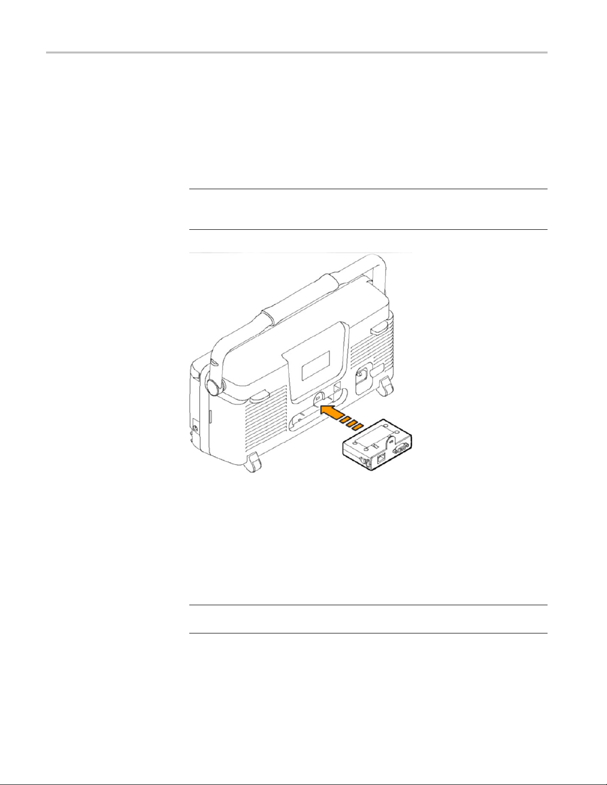
NOTE. In order to communicate via an Ethernet cable, you need to install an
optional DPO2CONN Connectivity Module into the back of the instrument. This
module includes both Ethernet and VGA video monitor ports.
ely communicate between your oscilloscope and PC via Ethernet,
Connecting via Ethernet
1-2 MSO2000B, DPO2000B, MSO2000 and DPO2000 Series Oscilloscopes Programmer Manual
If your PC is connected to a local area network, you can use an Ethernet cable to
ect your oscilloscope to the same network, and then use software to remotely
conn
control the oscilloscope via the PC. First, you’ll need to acquire an optional
DPO2CONN Connectivity Module, which provides Ethernet and video out ports
for your oscilloscope (search on www.tektronix.com). Then, simply plug one end
of the Ethernet cable into the Ethernet port (RJ-45 connector), and the other end
into your network connection.
OTE. You can connect an MSO/DPO2000B oscilloscope only to a 10/100
N
Base-T local area network.
Page 9

Getting Started
Connecting via USB
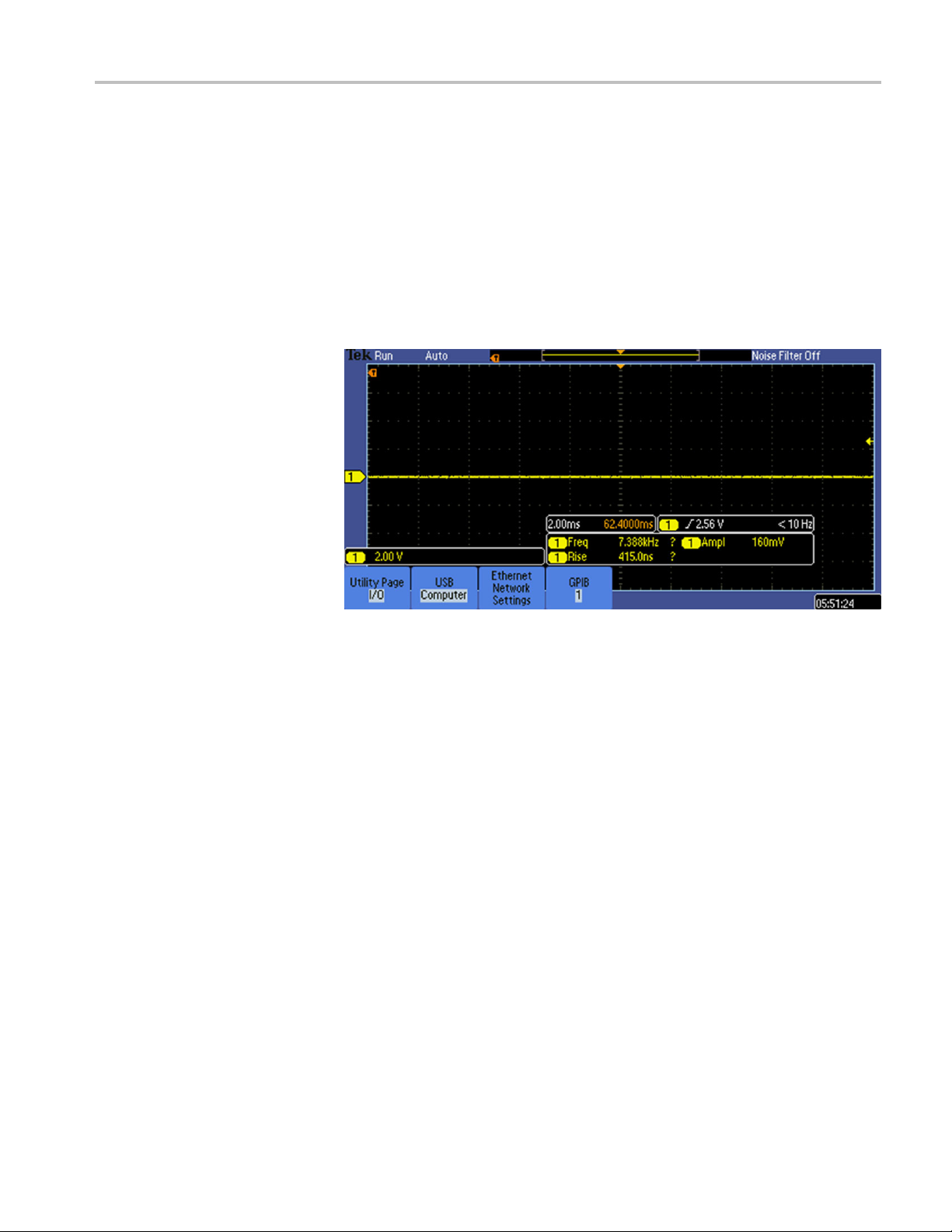
To view or chang
1. On the front panel, push Utility.
2. Push Utility Page.
3. Select I/O with the Multipurpose knob.
4. Push Ethernet Network Settings.
5. If you are on a DHCP Ethernet network and using a through cable, on the
side menu set DHCP/BOOTP to On.
6. If you are using a cross-over cable, set DHCP/BOOTP to Off,andseta
hard-coded TCPIP address.
You can co
cable, and then use software to remotely control the oscilloscope v ia the PC.
Simply plug one end of the cable into the USB 2.0 high-speed device port on
the rear panel of your oscilloscope, and the other end into a USB port on your
computer.
This port requires that the cable connected from the port to the host computer
meets the USB 2.0 specification for high speed connections. Typically, such
cables should be 3 feet or shorter in length, but this is determined by the quality of
able and, with higher quality cables, this length can be extended. (It is also
the c
dependent upon the drive capability of the host USB port to which the instrument
is connected.) The use of high quality short cables is recommended to avoid USB
connection problems.
e the Ethernet settings on your oscilloscope, do the following:
nnect your oscilloscope directly to a PC by using a high-speed USB
Once the USB cable is connected, the system automatically configures itself. To
verify that the USB is enabled:
1. On the front panel, push Utility.
2. Push Utility Page.
elect I/O with the Multipurpose knob.
3.S
4. Push USB, and verify that USB is enabled.
5. If USB is not enabled, push Enabled on the side menu.
After connection, the host, with appropriate software, can list the oscilloscope as a
USB device with the following parameters: (See Table 1-2.)
MSO2000B, DPO2000B, MSO2000 and DPO2000 Series Oscilloscopes Programmer Manual 1-3
Page 10

Getting Started
Table 1-2: USB D
Parameter Value
Manufacturer
Product ID
Serial number Serial number
Manufacturer description
Interface description “USBTMC-USB488”
evice Parameters
ID
0x0699 (decim
0x399 DPO200
0x39A MSO2002B (decimal 922)
0x39B DPO2004B (decimal 923)
0x39C MSO20
0x39D DPO2012B (decimal 925)
0x39E MSO2012B (decimal 926)
0x39F DPO20
0x3A0 MSO2014B (decimal 928)
0x3A1 DPO2022B (decimal 929)
0x3A2 MSO2
0x3A3 DPO2024B (decimal 931)
0x3A4 MSO2024B (decimal 932)
0x0372 DP
0x0373 DPO2014
0x0374 DPO2024
0x0376 M
0x0377 MSO2014
0x0378 MSO2024
“Tektronix”
al 1689)
2B (decimal 921)
04B (decimal 924)
14B (decimal 927)
022B (decimal 930)
O2012
SO2012
Connecting via GPIB
The oscilloscope has a USB 2.0 high-speed device port to control the oscilloscope
through USBTMC or GPIB with a TEK-USB-488 Adapter. The USBTMC
tocol allows USB devices to communicate using IEEE488 style messages.
pro
This lets you run your GPIB software applications on USB hardware.
To use GPIB, start by connecting an appropriate USB cable to the USB 2.0
igh-speed device port on the rear panel of your oscilloscope. Connect the other
h
end to the TEK-USB-488 Adapter host port. Then connect a GPIB cable from the
TEK-USB-488 Adapter to your PC.
Supply power to the Adapter in either of these two ways:
1-4 MSO2000B, DPO2000B, MSO2000 and DPO2000 Series Oscilloscopes Programmer Manual
Page 11

Getting Started
1. Use the optiona
on the Adapter.
2. Use an appropr
PC and the Device port on the TEK-USB-488 Adapter.
Before sett
(physical) GPIB interface, you should familiarize yourself with the following
GPIB requirements:
To function correctly, your oscilloscope must have a unique device address. The
defa
ing up the oscilloscope for remote communication using the electronic
A unique device address must be assigned to each device on the bus. No two
devices can share the same device address.
No more than 15 devices can be connected to any one line.
Only one d
No more than 65 feet (20 meters) of cable should be used to connect devices
to a bus.
At least two-thirds of the devices on the network should be powered on while
he network.
using t
Connect t he devices on the network in a star or linear configuration. Do not
op or parallel configurations.
use lo
ult setting for the GPIB configuration is GPIB Address 1.
l5V
iate USB cable connected to a powered USB host port on your
evice should be connected for every 6 feet (2 meters) of cable used.
power adapter connected to the 5 VDCpower input
DC
To change the GPIB address settings, do the following:
1. On the front panel, push Utility.
2. Push Utility Page.
3. Select I/O with the Multipurpose knob.
4. Push GPIB.
nter the GPIB address on the side menu, using the multipurpose knob. This
5.E
will set the GPIB address on an attached TEK-USB-488 Adapter
The oscilloscope is now set up for bidirectional communication with your PC.
Setting Up Remote Communications Software
Connect your oscilloscope directly to a computer to let the PC analyze your data,
collect screen images, or to control the oscilloscope using a program of your own
creation. You can connect using TekVISA drivers, or connect directly from any
computer’s web browser using Tektronix e*Scope Web-enabled tools.
MSO2000B, DPO2000B, MSO2000 and DPO2000 Series Oscilloscopes Programmer Manual 1-5
Page 12

Getting Started
Using TekVISA
NOTE. The CD tha
efficient connectivity between your oscilloscope and your computer. These include
toolbars that speed connectivity with Microsoft Excel and Word.
TekVISA lets you use your MS-Windows computer to acquire data from your
oscilloscope for use in an analysis package that runs on your PC, such as Microsoft
Excel, National Instruments LabVIEW, Tektronix OpenChoice Desktop software,
or your own custom software. You can use a common communications connection,
such as USB, Ethernet, or GPIB, to connect the computer to the oscilloscope.
The TekVIS
Desktop software that came with your instrument’s CD. You can also download
the OpenChoice Desktop software from www.tektronix.com\downloads.
NOTE. TekVISA cannot run if any other version of VISA drivers is installed.
To set up communications between your oscilloscope and a computer running
TekVISA drivers:
A drivers are automatically installed by installing the OpenChoice
t your oscilloscope shipped with contains additional tools for
1-6 MSO2000B, DPO2000B, MSO2000 and DPO2000 Series Oscilloscopes Programmer Manual
Page 13
Getting Started
1. Install the Tek
CD that came with your instrument or from the Tektronix website. This w ill
automatically install the TekVISA drivers.
2. Connect the oscilloscope to your computer with the appropriate USB, Ethernet
or GPIB cable. Cycle the power on the oscilloscope.
3. Push Utility.
4. Push Utilit
5. Turn multipurpose knob a and select I/O.
tronix OpenChoice Desktop software package, either from the
y Page.
sing Tektronix e*Scope
U
Software
6. If you are using USB, the system sets itself up automatically for you, if USB is
enabled. Check USB on the lower menu to be sure that USB is enabled. If it is
not enabled, push USB. Then push Connect to Computer on the side menu.
7. To use Ethernet, push Ethernet Network Settings on the lower menu. Use
the s ide menu buttons to adjust your network settings, as needed. For more
information, see the e*Scope setup information below.
8. If you are using GPIB, push GPIB. Enter the GPIB address on the side menu,
using multipurpose knob a. This will set the GPIB address on an attached
K-USB-488 Adapter.
TE
9. Run the application software on your computer.
Your oscilloscope contains a pre-installed remote control software package by
Tektronix called e*Scope. You can use this to “talk” to a networked PC’s web
browser so that you can view and control the oscilloscope wherever it is on your
network.
First, you’ll need to acquire an optional DPO2CONN Connectivity Module,
which provides Ethernet and video out ports for your oscilloscope (search on
www.tektronix.com).
MSO2000B, DPO2000B, MSO2000 and DPO2000 Series Oscilloscopes Programmer Manual 1-7
Page 14
Getting Started
To set up e*Scop
computer:
1. With the DPO2C
cable from the back of the oscilloscope to the same network as your computer.
2. Power u p you
a. Push the Utility button, and then push Utility Page on the bottom menu.
b. Turn multipurpose knob a to select I/O, and then push Ethernet Network
Settings on the bottom menu.
c. Push Test Connection on the side menu. The button should say OK.
e communications between your oscilloscope and a networked
ONN Connectivity Module installed, connect an Ethernet
r oscilloscope and test the network connection:
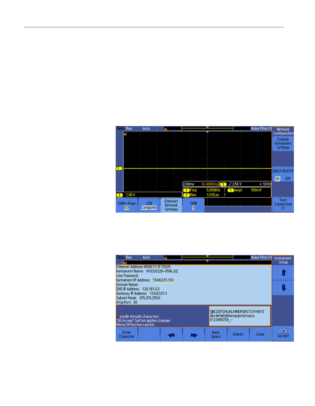
3. Next, find your oscilloscope’s IP address:
a. Push Change Instrument Settings on the side menu to display the
network parameters configured on your oscilloscope.
b. Note down the Instrument IP address.
1-8 MSO2000B, DPO2000B, MSO2000 and DPO2000 Series Oscilloscopes Programmer Manual
Page 15
Getting Started
Documentation
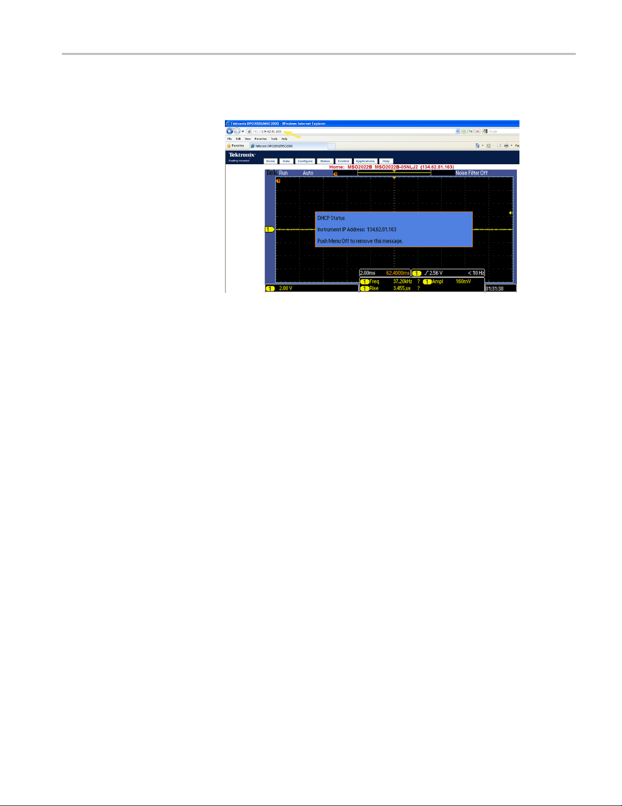
4. On the menu bar o
Instrument IP address and press Enter.
5. You should now s ee the e*Scope screen on your PC and an image of your
oscillos
oscilloscope from your PC’s browser.
cope’s display. You may use the menu items at the top to control your
f your PC’s web browser, type in the oscilloscope’s
The following documents are available for download on the Manuals Finder
Web site at www.tektronix.com:
MSO/DPO2000B Series User Manual. Information about installing and
operating the oscilloscope.
MSO/DPO2000B Series Technical Reference. Oscilloscope specifications and
a performance verification procedure.
TekVISA Programmer Manual. Description of TekVISA, the Tektronix
implementation of the VISA Application Programming Interface (API). TekVISA
is industry-compliant software for writing interoperable oscilloscope drivers in a
variety of Application Development Environments (ADEs).
MSO2000B, DPO2000B, MSO2000 and DPO2000 Series Oscilloscopes Programmer Manual 1-9
Page 16

Getting Started
1-10 MSO2000B, DPO2000B, MSO2000 and DPO2000 Series Oscilloscopes Programmer Manual
Page 17

Command Syntax
You can control the operations and functions of the oscilloscope through the
Ethernet port or the USB 2.0 device port using commands and queries. The
related topi
The topics also describe the conventions that the oscilloscope uses to process
them. See the Command Groups topic in the table of contents for a listing of the
commands by command group, or use the index to locate a specific command.
cs listed below describe the syntax of these commands and queries.
Backus-Naur Form
Notation
This documentation describes the commands and queries using Backus-Naur
Form (BNF) notation. Refer to the following table for the symbols that are used.
Table 2-1: Symbols for Backus-Naur Form
Symbol Meaning
<>
=
| Exclusive OR
{ } Group; one element is required
[]
.. .
( ) Comment
Command and Query Structure
mmands consist of set commands and query commands (usually called
Co
commands and queries). Commands modify oscilloscope settings or tell the
oscilloscope to perform a specific action. Queries cause the oscilloscope to return
data and status information.
Defined element
Is defined as
Optional; can be omitted
Previous element(s) may be repeated
Most commands have both a set form and a query form. The query form of the
command differs from the set form by its question mark at the end. For example,
the set command
commands have both a set and a query form. Some commands have set only and
some have query only.
Messages
MSO2000B, DPO2000B, MSO2000 and DPO2000 Series Oscilloscopes Programmer Manual 2-1
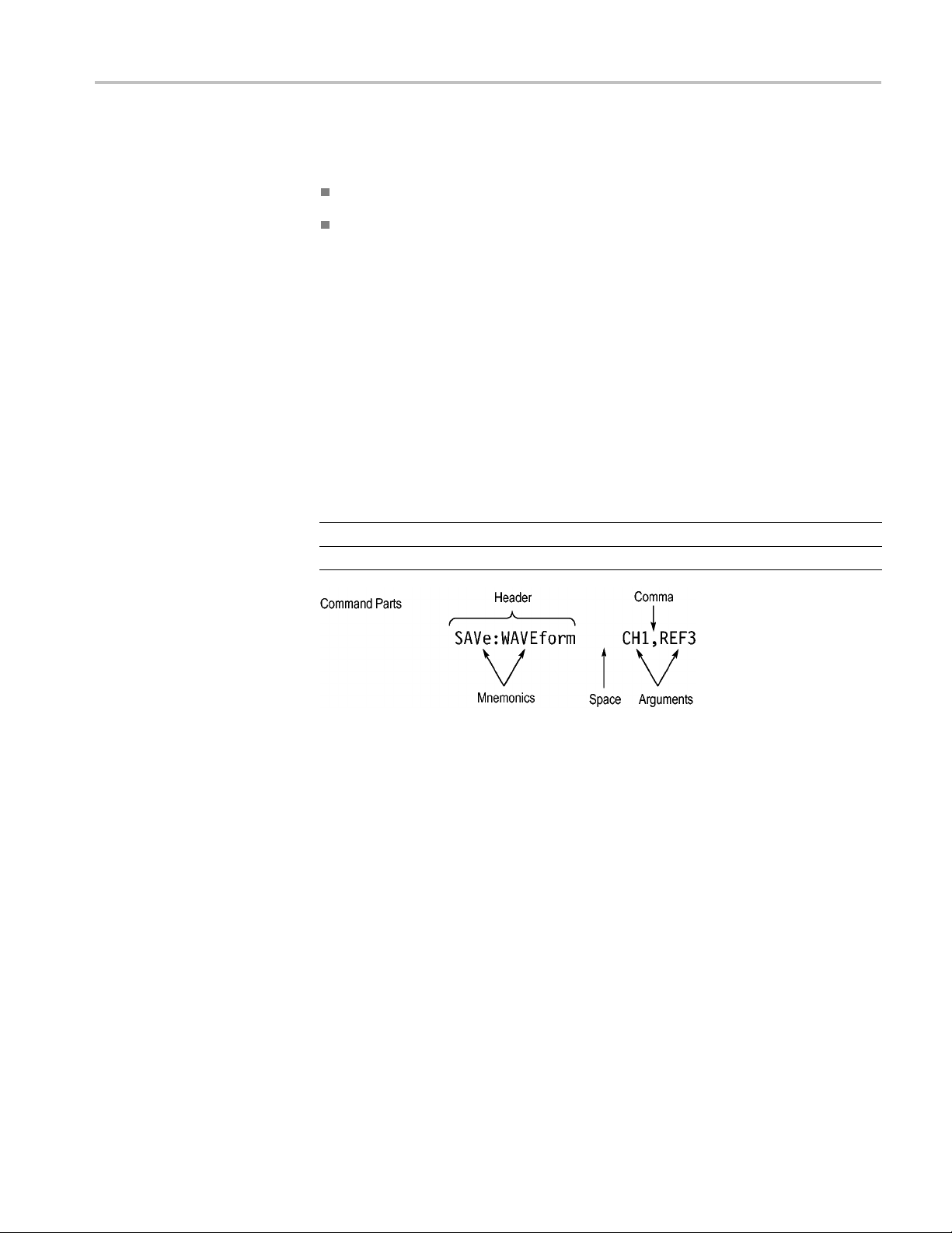
A command message is a command or query name followed by any information
the oscilloscope needs to execute the command or query. Command messages
may c ontain five element type s, defined in the following table.
ACQuire:MODe has a query form ACQuire:MODe?.Notall
Page 18

Command Syntax
Commands
Table 2-2: Comm
Symbol Meaning
<Header>
<Mnemonic>
<Argument
<Comma> A single c
<Space>
Comman
>
ds cause the oscilloscope to perform a specific function or change one of
and Message Elements
This is the basic command name. If the header ends with a question
mark, the command is a query. The header may begin with a colon
(:) characte
the beginning colon is required. Never use the beginning colon with
command headers beginning with a star (*).
This is a header subfunction. Some command headers have only one
mnemonic. I
character always separates them from each other.
This is a qu
Some commands have no arguments while others have multiple
arguments. A <space> separates arguments from the header. A
<comma> se
commands. Optionally, there may be white space characters before
and after the comma.
A white space character is used between a command header and the
related argument. Optionally, a white space may consist of multiple
white sp
r. If the command is concatenated with other commands,
f a command header has multiple mnemonics, a colon (:)
antity, quality, restriction, or limit associated with the header.
parates arguments from each other.
omma is used between arguments of multiple-argument
ace characters.
the settings. Commands have the structure:
eader>[<Space><Argument>[<Comma> <Argument>]...]
[:]<H
A command header consists of one or more mnemonics arranged in a hierarchical
ee structure. The first mnemonic is the base or root of the tree and each
or tr
subsequent mnemonic is a level or branch off the previous one. Commands at a
higher level in the tree may affect those at a lower level. The leading colon (:)
always returns you to the base of the command tree.
2-2 MSO2000B, DPO2000B, MSO2000 and DPO2000 Series Oscilloscopes Programmer Manual
Page 19
Command Syntax
Queries
Headers
Queries cause t
he oscilloscope to return status or setting information. Queries
have the structure:
[:]<Header>
[:]<Header>[<Space><Argument> [<Coma><Argument>]...]
You can specify a query command at any level within the command tree unless
otherwise noted. These branch queries return information about all the mnemonics
below the sp
ecified branch or level.
Use the HEADer command to control whether the oscilloscope returns headers as
part of the query response. If header is on, the query response returns command
headers,
then formats itself as a valid set command. When header is off, the
response includes only the values. This may make it easier to parse and extract the
information from the response. The table below shows the difference in responses.
Table 2-3: Comparison of Header Off and Header On Responses
Query Header Off Header On
TIME?
ACQuire:NUMAVg?
14:30:00 :TIME “14:30:00”
100
:ACQUIRE:NUMAVG 100
MSO2000B, DPO2000B, MSO2000 and DPO2000 Series Oscilloscopes Programmer Manual 2-3
Page 20

Command Syntax
Clearing the o
scilloscope
Command Entry
Abbrev
iating
You can clear the Output Queue and reset the oscilloscope to accept a new
command or query by using the selected Device Clear (DCL) function.
The following rules apply when entering commands:
You can enter commands in upper or lower case.
You can precede any command with white space characters. White space
characters include any combination of the ASCII control characters 00 through
09 and 0B through 20 hexadecimal (0 through 9 and 11 through 32 decimal).
The oscilloscope ignores commands consisting of a ny combination of white
space characters and line feeds.
You can abbreviate many oscilloscope commands. Each command in this
documentation shows the minimum acceptable abbreviations in capitals. For
example, you can enter the command ACQuire:NUMAvg simply as ACQ:NUMA
:numa.
or acq
Concatenating
Abbreviation rules may change over time as new oscilloscope models are
oduced. Thus, for the most robust code, use the full spelling.
intr
If you use the HEADer command to have command headers included as part
uery responses, you can further control whether the returned headers are
of q
abbreviated or are full-length with the VERBose command.
You can concatenate any combination of set commands and queries using a
micolon (;). The oscilloscope executes concatenated commands in the order
se
received.
2-4 MSO2000B, DPO2000B, MSO2000 and DPO2000 Series Oscilloscopes Programmer Manual
Page 21

Command Syntax
When concatena
ting commands and queries, you must follow these rules:
1. Separate completely different headers by a semicolon and by the beginning
colon on all commands except the first one. For example, the commands
TRIGger:MODe NORMal and ACQuire:NUMAVg 8, can be concatenated
into the following single command:
TRIGger:MODe NORMal;:ACQuire:NUMAVg 8
2. If concatenated commands have headers that differ by only the last mnemonic,
you can abbreviate the second command and eliminate the beginning colon.
For example, you can concatenate the commands
ACQuire:MODe AVErage
and ACQuire:NUMAVg 8 into a single command:
ACQuire:MODe AVErage; NUMAVg 8
The longer version works equally well:
ACQuire:MODe AVErage;:ACQuire:NUMAVg 8
3. Never precede a star (*) command with a colon:
ACQuire:STATE 1;*OPC
Any commands that follow will be processed as if the star command was
not there so the commands,
ACQuire:MODe ENVelope;*OPC;NUMAVg 8
will set the acquisition mode to envelope and set the number of acquisitions
for averaging to 8.
Terminating
4. When you concatenate queries, the responses to all the queries are
concatenated into a single response message.
5. Set commands and queries may be concatenated in the same message. For
example,
ACQuire:MODe SAMple;NUMAVg?;STATE?
is a valid message that sets the acquisition mode to sample. The message then
queries the number of acquisitions for averaging and the acquisition state.
Concatenated comma nds and queries are executed in the order received.
Here are some invalid concatenations:
HORizontal:SCAle 400E-9;ACQuire:NUMAVg 8 (no colon before
ACQuire)
DISPlay:GRAticule FULL;:*TRG (colon before a star (*) command)
MATH:HORizontal:SCAle 1.0e-1;HORizontal:POSition 5.0el
(levels of the mnemonics are different; either remove the second use of
HORizontal: or place :MATH in front of HORizontal:POSition)
This documentation uses <EOM> (End of Message) to represent a message
terminator.
MSO2000B, DPO2000B, MSO2000 and DPO2000 Series Oscilloscopes Programmer Manual 2-5
Page 22

Command Syntax
Table 2-4: End o
Symbol Meaning
<EOM>
The end-of-message terminator must be the END message (EOI asserted
concurrently with the last data byte). The last data byte may be an ASCII line
feed (LF) character.
This oscilloscope does not support ASCII LF only message termination. The
oscilloscope always terminates outgoing messages with LF and EOI.
Constructed Mnemonics
Some header mnemonics specify one of a range of mnemonics. For example, a
channel
in the command just as you do any other mnemonic. For example, there is a
CH1:POSition command, and there is also a CH2:POSition command. In the
command descriptions, this list of choices is abbreviated as CH<x>.
Cursor Position
Mnemonics
When cursors are displayed, commands may specify which cursor of the pair to
use.
f Message Terminator
Message termi
nator
mnemonic can be CH1, CH2, CH3, or CH4. You use these mnemonics
Math Specifier Mnemonics
Table 2-5: Channel Mnemonics
Symbol Meaning
CH<x> A channel specifier; <x> is 1 through 4.
Table 2-6: Cursor Mnemonics
Symbol Meaning
CURSOR<x>
POSITION<x>
HPOS<x>
A cursor selector; <x> is either 1 or 2.
A cursor selector; <x> is either 1 or 2.
A cursor selector; <x> is either 1 or 2.
Commands can specify the mathematical waveform to use as a mnemonic in
the header.
Table 2-7: Math Specifier Mnemonics
Symbol Meaning
Math<x>
A math waveform specifier; <x> is 1.
2-6 MSO2000B, DPO2000B, MSO2000 and DPO2000 Series Oscilloscopes Programmer Manual
Page 23

Command Syntax
Measurement Specifier
Mnemonics
Channel Mnemonics
Reference Waveform
Mnemonics
Commands can sp
ecify which measurement to set or query as a mnemonic in the
header. Up to four automated measurements may be displayed.
Table 2-8: Measurement Specifier Mnemonics
Symbol Meaning
MEAS<x> A measurement specifier; <x> is 1 through 4.
Commands specify the channel to use as a mnemonic in the header.
Commands can specify the reference waveform to use as a mnemonic in the
header.
Table 2-9: Re f erence Waveform Mnemonics
Symbol Meaning
REF<x>
A reference waveform specifier; <x> 1 or 2. The MSO/DPO2000B and
MSO/DPO2000 series provides only two REF waveforms regardless of
whether the instrument is a 2 or 4 channel model.
Argument Types
Numeric
Quoted String
ny oscilloscope commands require numeric arguments. The syntax shows
Ma
the format that the oscilloscope returns in response to a query. This is also the
preferred format when sending the command to the oscilloscope though any of
the formats will be accepted. This documentation represents these arguments as
described below.
Table 2-10: Numeric Arguments
Symbol Meaning
<NR1>
<NR2> Floating point value without an exponent
<NR3> Floating point value with an exponent
<bin>
Most num
eric arguments will be automatically forced to a valid setting, by either
Signed integer value
Digital data in binary format
rounding or truncating,, when an invalid number is input, unless otherwise noted
in the command description.
Some commands accept or return data in the form of a quoted string, which is
simply a group of ASCII characters enclosed by a single quote (') or double quote
("). The following is an example of a quoted string:
string"
. This documentation represents these arguments as follows:
"This is a quoted
MSO2000B, DPO2000B, MSO2000 and DPO2000 Series Oscilloscopes Programmer Manual 2-7
Page 24

Command Syntax
Table 2-11: Quo
Symbol Meaning
<QString> Quoted string of AS CII text
ted String Argument
A quoted string can include any character defined in the 7-bit ASCII character
set. Follow these rules when you use quoted strings:
1. Use the same type of quote character to open and close the string. For
example:
"this is a valid string".
2. You can mix quotation marks within a string as long as you follow the
previous rule. For example:
"this is an 'acceptable' string".
3. You can include a quote character within a string by repeating the quote. For
example:
"here is a "" mark".
4. Strings can have upper or lower case characters.
5. If you use a GPIB network, you cannot terminate a quoted string with the
END message before the closing delimiter.
6. A carriage return or line feed embedded in a quoted string does not terminate
the string. The return is treated as another character in the string.
7. The maximum length of a quoted string returned from a query is 1000
characters.
Block
Here are some invalid strings:
"Invalid string argument' (quotes are not of the same type)
st<EOI>"
"te
(termination character is embedded in the string)
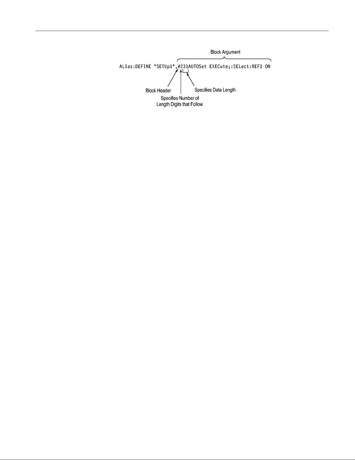
Several oscilloscope commands use a block argument form, as defined in the
table below.
able 2-12: Block Argument
T
Symbol Meaning
NZDig>
<
<Dig>
<DChar> A character with the hexadecimal equivalent of 00 through FF (0
<Block>
A nonzero digit character in the range of 1–9
A digit character, in the range of 0–9
through 255 decimal)
A block of data bytes defined as: <Block> ::=
{#<NZDig><Dig>[<Dig>...][<DChar>...] |#0[<DChar>...]<terminator>}
<NZDig> specifies the number of <Dig> elements that follow. Taken together,
the <NZDig> and <Dig> elements form a decimal integer that specifies how
many <DChar> elements follow.
2-8 MSO2000B, DPO2000B, MSO2000 and DPO2000 Series Oscilloscopes Programmer Manual
Page 25
Command Syntax
MSO2000B, DPO2000B, MSO2000 and DPO2000 Series Oscilloscopes Programmer Manual 2-9
Page 26

Command Syntax
2-10 MSO2000B, DPO2000B, MSO2000 and DPO2000 Series Oscilloscopes Programmer Manual
Page 27

Command Groups
This manual lists the MSO/DPO2000B and MSO/DPO2000 series IEEE488.2
commands in two ways. First, it presents them by functional groups. Then, it lists
them alphabe
list provides detail on each command. (See page 2-59, Commands Listed in
Alphabetical Order.)
Acquisition Command Group
Use the commands in the Acquisition Command Group to set up the modes and
functions that control how the oscilloscope acquires signals input to the channels,
and processes them into waveforms.
Using the commands in this group, you can do the following:
Start and stop acquisitions.
Control whether each waveform is simply acquired, averaged over successive
acquisitions of that waveform.
Set the controls or conditions that start and stop acquisitions.
Contr
tically. The functional group list starts b elow. The alphabetical
ol acquisition of channel waveforms.
Set acquisition parameters.
e 2-13: Acquisition Commands
Tabl
Command Description
urns acquisition parameters
ACQuire?
ACQuire:MAXSamplerate?
ACQuire:MODe Sets or returns the acquisition mode
ACQuire:NUMACq? Returns number of acquisitions that have
ACQuire:NUMAVg Sets or returns the number of acquisitions for
ACQuire:STATE Starts or stops the acquisition system
ACQuire:STOPAfter Sets or returns whether the acquisition is
Ret
urns the maximum real-time sample rate
Ret
occurred
an averaged waveform
continuous or single sequence
MSO2000B, DPO2000B, MSO2000 and DPO2000 Series Oscilloscopes Programmer Manual 2-11
Page 28

Command Groups
Alias Command
Group
Use the Alias commands to define new commands as a sequence of standard
commands. You may find this useful when repeatedly using the same commands
to perform ce
rtain tasks like setting up measurements.
Aliases are similar to macros but do not include the capability to substitute
parameters
into alias bodies. The alias mechanism obeys the following rules:
The alias name must consist of a valid IEEE488.2 message unit, which may
not appear
in a message preceded by a colon, comma, or a command or query
program header.
The a lias
name may not appear in a message followed by a colon, comma,
or question mark.
An alias
name must be distinct from any keyword or keyword short form.
An alias name cannot be redefined without first b eing deleted using one of
as deletion functions.
the ali
Alias names do not appear in response messages.
2-14: Alias Commands
Table
Command Description
s
ALIa
ALIas:CATalog? Returns a list of the currently defined alias
ALIas:DEFine
ALIas:DELEte
ALIas:DELEte:ALL Deletes all existing aliases
ALIas:DELEte[:NAMe]
ALIas[:STATE] Sets or returns the alias state
Sets or returns the alias state
labels
Assigns a sequence of program messages
n alias label
to a
moves a specified alias
Re
Removes a specified alias
2-12 MSO2000B, DPO2000B, MSO2000 and DPO2000 Series Oscilloscopes Programmer Manual
Page 29

Command Groups
Bus Command Gr
oup
Use the Bus commands when working with serial bus measurements.
Install the DPO2EMBD application module when working with I2CorSPI
bus signals.
Install the DPO2AUTO module when working with CAN or LIN bus signals.
Install the DPO2COMP module when working with RS232 bus signals.
Table2-15: BusCommands
Commands Description
BUS Returns the parameters for each bus
BUS:B<x>:CAN:BITRate Sets or returns the bit rate for the CAN bus
BUS:B<x>:CAN:PRObe Sets or returns the probing method used to
probe the CA N bus
BUS:B<x>:CAN:SAMPLEpoint Sets or returns the sample point (in %) to
sample during each bit period
BUS:B<x>:CAN:SOUrce Sets or returns the CAN data source
BUS:B<x>:DISplay:FORMAt Sets the display format for the numerical
information in the specified bus waveform
BUS:B<x>:I2C:ADDRess:RWINClude Sets and returns whether the read/write bit is
included in the address
BUS:B<x>:I2C{:CLOCK|:SCLK}:SOUrce Sets or returns the I2C SCLK source
BUS:B<x>:I2C{:DATA|:SDATA}:SOUrce Sets or returns the I2C SDATA source
BUS:B<x>:LABel Sets or returns the waveform label for the
specified bus
BUS:B<x>:LIN:BITRate Sets or returns the bit rate for LIN
BUS:B<x>:LIN:IDFORmat Sets or returns the LIN ID format
BUS:B<x>:LIN:POLARity Sets or returns the LIN polarity
BUS:B<x>:LIN:SAMPLEpoint Sets or returns the sample point (in %) at
which to sample during each bit period
BUS:B<x>:LIN:SOUrce Sets or returns the LIN data source
BUS:B<x>:LIN:STANDard Sets or returns the LIN standard
BUS:B<x>:PARallel:BIT<x>:SOUrce Sets or returns the parallel bit <x> source
BUS:B<x>:PARallel:CLOCK:EDGE Sets or returns the parallel clock edge for
bus <x>
BUS:B<x>:PARallel:CLOCK:ISCLOCKed Sets or returns whether the parallel bus is
clocked
BUS:B<x>:PARallel:CLOCK:SOUrce Sets or returns the parallel bus<x> clock
source
BUS:B<x>:PARallel:WIDth Sets or returns the number of bits used for
the width of the parallel bus <x>
MSO2000B, DPO2000B, MSO2000 and DPO2000 Series Oscilloscopes Programmer Manual 2-13
Page 30

Command Groups
Table2-15: BusCommands(cont.)
Commands Description
BUS:B<x>:POSition Sets or returns the position of the specified
bus waveform
BUS:B<x>:RS232C:BITRate Sets or returns the RS232 bit rate for the
specified bus
BUS:B<x>:RS232C:DATABits Sets or returns the number of bits for the
data frame
BUS:B<x>:RS232C:DELIMiter Sets or returns the RS232 delimiting value
for a packet on the specified bus
BUS:B<x>:RS232C:DISplaymode Sets or returns the display mode for the
specified bus display and event table
BUS:B<x>:RS232C:PARity Sets or returns parity for RS232 data
BUS:B<x>:RS232C:POLarity Sets or returns the RS232C polarity for the
specified bus
BUS:B<x>:RS232C:RX:SOUrce Sets or returns the RS232 RX source
BUS:B<x>:RS232C:TX:SOUrce Sets or returns the RS232 TX Source
BUS:B<x>:SPI{:CLOCK|:SCLK}:POLARity Sets or returns the SPI SCLK polarity
BUS:B<x>:SPI{:CLOCK|:SCLK}:SOUrce Sets or returns the SPI SCLK source
BUS:B<x>:SPI:DATA{:IN|:MISO}:POLARity Sets or returns the SPI MISO polarity
BUS:B<x>:SPI:DATA{:IN|:MISO}:SOUrce Sets or returns the SPI MISO source
BUS:B<x>:SPI:DATA{:OUT|:MOSI}:
POLARity
BUS:B<x>:SPI:DATA{:OUT|:MOSI}:SOUrce Sets or returns the SPI MOSI source
BUS:B<x>:SPI{:SELect|:SS}:POLARity Sets or returns the SPI SS polarity
BUS:B<x>:SPI{:SELect|:SS}:SOUrce Sets or returns the SPI SS source
BUS:B<x>:SPI:BITOrder Sets or returns the bit order for the specified
BUS:B<x>:SPI:DATA:SIZe Sets or returns the number of bits per word
BUS:B<x>:SPI:FRAMING Sets or returns the type of SPI framing
BUS:B<x>:SPI:IDLETime Sets or returns the SPI bus idle time in
BUS:B<x>:STATE Turns the specified bus on and off
BUS:B<x>:TYPE Sets or returns the specified bus type
BUS:LOWerthreshold:CH<x> Sets or returns the lower threshold for each
BUS:THReshold:CH<x> Sets or returns the threshold for a channel
BUS:UPPerthreshold:CH<x> Sets or returns the upper threshold for each
BUS:THReshold:D<x> Sets or returns the threshold for digital
Sets or returns the SPI MOSI polarity
SPI bus
for the specified SPI bus
seconds for the specified SPI bus
channel
channel
channel
2-14 MSO2000B, DPO2000B, MSO2000 and DPO2000 Series Oscilloscopes Programmer Manual
Page 31

Command Groups
Table 2-15: Bus Commands (cont.)
Commands Description
SEARCH:SEARCH<x>:TRIGger:A:BUS?
SEARCH:SEARCH<x>:TRIGger:A:BUS:
B<x>:LIN:CONDition
SEARCH:SEARCH<x>:TRIGger:A:BUS:
B<x>:LIN:DATa:HIVALue
SEARCH:SEARCH<x>:TRIGger:A:BUS:
B<x>:LIN:DATa:QUALifier
SEARCH:SEARCH<x>:TRIGger:A:BUS:
B<x>:LIN:DATa:SIZe
SEARCH:SEARCH<x>:TRIGger:A:BUS:
B<x>:LIN:DATa:VALue
SEARCH:SEARCH<x>:TRIGger:A:BUS:
B<x>:LIN:ERRTYPE
SEARCH:SEARCH<x>:TRIGger:A:BUS:
B<x>:LIN:IDentifier:VALue
SEARCH:SEARCH<x>:TRIGger:A:BUS:
B<x>:RS232C:CONDition
SEARCH:SEARCH<x>:TRIGger:A:BUS:
B<x>:RS232C:RX:DATa:SIZe
SEARCH:SEARCH<x>:TRIGger:A:BUS:
B<x>:RS232C:RX:DATa:VALue
TRIGger:A:BUS:B<x>:LIN:CONDition Sets or returns the trigger condition for LIN
TRIGger:A:BUS:B<x>:LIN:DATa:HIVALue Sets or returns the binary data string to be
TRIGger:A:BUS:B<x>:LIN:DATa:QUALifier Sets or returns the LIN data qualifier
TRIGger:A:BUS:B<x>:LIN:DATa:SIZe Sets or returns the length of the data string
TRIGger:A:BUS:B<x>:LIN:DATa:VALue Sets or returns the binary data string
TRIGger:A:BUS:B<x>:LIN:ERRTYPE Sets or returns the error type
TRIGger:A:BUS:B<x>:LIN:IDentifier:VALue Sets or returns the binary address string
TRIGger:A:BUS:B<x>:RS232C:RX:DATa:
SIZe
TRIGger:A:BUS:B<x>:RS232C:RX:DATa:
VALue
TRIGger:A:BUS:B<x>:RS232C:TX:DATa:
SIZe
TRIGger:A:BUS:B<x>:RS232C:TX:DATa:
VALue
Returns the serial search type
Sets or returns the search condition for a LIN
search
Sets or returns the binary data string
Sets or returns the LIN data quali fier
Sets or returns the length of the data string
in bytes
Sets or returns the binary data string used
for a LIN search
Sets or returns the error type used for a LIN
Search
Sets or returns the binary address string
used for LIN search
Sets or returns the trigger condition for a
RS232 trigger
Sets or returns the length of the data string
for a RS232 RX trigger
Sets or returns the binary data string for a
RX RS232 trigger
used for LIN trigger
in bytes to be used for LIN trigger
used for LIN trigger
Sets or returns the length of the data string
for a RX RS232 trigger
Sets or returns the binary data string for a
RX RS232 trigger
Sets or returns the length of the data string
to be used for a TX RS232 Trigger
Sets or returns the binary data string to be
used for a TX RS232 trigger
MSO2000B, DPO2000B, MSO2000 and DPO2000 Series Oscilloscopes Programmer Manual 2-15
Page 32

Command Groups
Calibration a
nd Diagnostic Command Group
The Calibration and Diagnostic commands provide i nformation about the current
state of oscilloscope calibration. They also initiate internal signal path calibration
(SPC)orexec
calibration are not described in this manual. They are described in the Service
manual, available for download at www.tektronix.com.
Table 2-16: Calibration and Diagnostic Commands
Command
*CAL? Instructs the oscilloscope to perform
CALibrate:FACtory Provides the controls for starting and
CALibrate:FACtory:STATus? Returns the factory calibration status value
CALibrate:INTERNal Starts a signal path compensation
CALibrate:INTERNal:STARt Starts the internal signal path calibration
CALibrate:INTERNal:STATus? Returns the current status of the internal
CALibrate:RESults? Returns the status of all calibration
CALibrate:RESults:FACtory? Returns the status of internal and factory
CALibrate:RESults:SPC? Returns the results of the last SPC operation
CALibrate:TEMPerature? Returns 0 as MSO/DPO2000/B series
DIAg:LOOP:OPTion Sets the self-test loop option
DIAg:LOOP:OPTion:NTIMes Sets the self-test loop option to run N times
DIAg:LOOP:STOP Stops the self-test at the end of the current
DIAg:RESUlt:FLAg? Returns the pass/fail status from the last
DIAg:RESUlt:LOG? Returns the internal results log from the last
DIAg:SELect:<function> Selects one of the available s elf-test areas
DIAg:STATE Sets the oscilloscope operating state
DIAg:SELect Runs self tests on the specified system
ute diagnostic tests. Commands that are specifictofactory
Description
self-calibration and returns the oscilloscope
self calibration status
stopping the factory calibration process
saved in nonvolatile memory
signal path calibration
subsystems without performing an SPC
operation
calibration
does not support recording of oscilloscope
temperature
loop
self-test sequence execution
self-test sequence execution
subsystem
2-16 MSO2000B, DPO2000B, MSO2000 and DPO2000 Series Oscilloscopes Programmer Manual
Page 33

Command Groups
Cursor Comman
dGroup
Use the commands in the Cursor Command Group to control the cursor display
and readout. You can use these commands to control the setups for cursor 1 and
cursor 2, suc
You can also use the commands to select one of the following cursor functions:
Table 2-17: Cursor Commands
Command
CURSor?
CURSor:FUNCtion Sets or returns the cursor type
CURSor:HBArs?
CURSor:HBArs:DELTa? Returns hbars cursors vertical difference
CURSor:HBArs:POSITION<x> Sets or returns the hbar cursor<x> vertical
CURSor:HBArs:UNIts
CURSor:HBArs:USE Sets the horizontal bar cursor measurement
CURSor:MODe Sets or returns whether cursors move in
CURSor:VBArs? Sets or returns the position of vertical bar
CURSor:VBArs:ALTERNATE<x>? Returns the alternate readout for the
CURSor:VBArs:DELTa? Returns the difference between vbar cursors
CURSor:VBArs:HPOS<x>? Returns the horizontal value of the specified
CURSor:VBArs:POSITION<x> Sets or returns the vbar cursor<x> horizontal
CURSor:VBArs:UNIts Sets or returns the units for vbar cursors
CURSor:VBArs:USE Sets the vertical bar cursor measurement
CURSor:VBArs:VDELTa? Returns the vertical difference between the
CURSor:XY:POLar:RADIUS:DELta? Returns the difference between the cursors
h as cursor position.
Off. Turns off the display of all cursors.
Waveform Cursors. Consists of two cursors. Waveform cursors enable you to
conveniently measure waveform amplitude and time.
Screen Cursors. Consists of two pairs of independent horizontal and vertical
cursors. You can use these cursors to indicate an arbitrary position within
the waveform display area.
Description
Returns cursor settings
Returns hbar cursor settings
position
Returns hbar cursor units
scale
unison or separately
cursors
waveform (Vbar) cursors
vertical bar ticks
position
scale
two vertical bar cursor ticks
X radius and the c ursor Y radius
MSO2000B, DPO2000B, MSO2000 and DPO2000 Series Oscilloscopes Programmer Manual 2-17
Page 34

Command Groups
Table 2-17: Cursor Commands (cont.)
Command
CURSor:XY:POLar:RADIUS:POSITION<x>? Returns the polar radius of the specified
CURSor:XY:POLar:RADIUS:UNIts?
CURSor:XY:POLar:THETA:DELta?
CURSor:XY:POLar:THETA:POSITION<x>?
CURSor:XY:POLar:THETA:UNIts?
CURSor:XY:PRODUCT:DELta? Returns the difference between the cursors
CURSor:XY:PRODUCT:POSITION<x>? Returns the position of the X or Y cursor used
CURSor:XY:PRODUCT:UNIts?
CURSor:XY:RATIO:DELta? Returns the ratio of the difference between
CURSor:XY:RATIO:POSITION<x>? Returns the X or Y position for the specified
CURSor:XY:RATIO:UNIts? Returns the X and Y cursor units for the ratio
CURSor:XY:RECTangular:X:DELta?
CURSor:XY:RECTangular:X:POSITION<x> Sets or returns the cursor X rectangular
CURSor:XY:RECTangular:X:UNIts? Returns the Cursor X rectangular units
CURSor:XY:RECTangular:Y:DELta?
CURSor:XY:RECTangular:Y:POSITION<x>> Sets or returns the cursor Y rectangular
CURSor:XY:RECTangular:Y:UNIts?
Description
cursor
Returns the polar radius units
Returns the XY cursor polar coordinate delta
Returns the cursor X or cursor Y polar
coordinate
Returns the cursor polar coordinate units
X position and cursor Y position
to calculate the X × Y cursor measurement
Returns the XY cursor product units
the cursor X position and cursor Y position
cursor
measurement
Returns the cursor X delta value in
rectangular coordinates
coordinates
Returns The cursor Y delta value in
rectangular coordinates
coordinates
Returns the cursor Y rectangular units
Display Command Group
Use the commands in the Display Command Group to change the graticule style,
the displayed intensities, and to set the c haracteristics of the waveform display.
Use these commands to set the style that best displays your waveforms and
graticule display properties. Note that the mode you choose globally affects all
displayed waveforms.
2-18 MSO2000B, DPO2000B, MSO2000 and DPO2000 Series Oscilloscopes Programmer Manual
Page 35

Command Groups
Table 2-18: Dis
Command
DISplay?
DISplay:CLOCk Sets or returns the display of the date/time
DISplay:DIGital:HEIght Sets or returns the height of the digital
DISplay:FORMat Sets or returns the display format
DISplay:GRAticule Sets or returns the type of graticule that is
DISplay:INTENSITy?
DISplay:INTENSITy:BACKLight Sets or returns the backlight intensity for the
y:INTENSITy:GRAticule
DISpla
DISplay:INTENSITy:WAVEform Sets or returns the intensity of the waveforms
DISplay:PERSistence Sets or returns display persistence setting
MESSage:BOX Sets or returns the size and position of the
MESSage:CLEAR Removes the message text from the
Sage:SHOW
MES
SSage:STATE
ME
play Commands
Description
Returns curre
stamp
display and
you can display
displayed
Returns all display intensity settings
display
Sets or
display
message window
sage window
mes
ars the contents of the message window
Cle
ntrols the display of the message window
Co
nt display settings
the number of waveforms that
returns the graticule intensity for the
Ethernet Command Group
Use the commands in the Ethernet Command Group to set up the Ethernet remote
interface.
Table 2-19: Ethernet Commands
Command
ETHERnet:DHCPbootp Sets or returns the network initialization
ETHERnet:DNS:IPADDress Sets or returns the network Domain Name
ETHERnet:DOMAINname Sets or returns the network domain name
ETHERnet:ENET:ADDress?
ETHERnet:GATEWay:IPADDress Sets or returns the remote interface gateway
Description
search for a DHCP/BOOTP server
Server (Dns) IP address
Returns the Ethernet address value assigned
to the oscillosc ope
IP address
MSO2000B, DPO2000B, MSO2000 and DPO2000 Series Oscilloscopes Programmer Manual 2-19
Page 36

Command Groups
Table 2-19: Ethernet Commands (cont.)
Command
ETHERnet:HTTPPort
ETHERnet:IPADDress
ETHERnet:NAME
ETHERnet:PASSWord Sets or returns the Ethernet access password
ETHERnet:PING Causes the oscilloscope to ping the gateway
ETHERnet:PING:STATUS? Returns the results from pinging the gateway
ETHERnet:SUBNETMask Sets or returns the remote interface subnet
File System Command Group
Use the commands in the File System Command Group to access USB media.
You can use the commands to do the following:
List the contents of a directory
Description
Sets or returns the remote interface HTTP
port value
Sets or returns the IP address assigned to
the oscilloscope
Sets or returns the network name assigned
to the o scillos cope
IP address
IP address
mask value
Create, rename and delete directories
Create,read,rename,ordeleteafile
Format media
When using these commands, keep the following points in mind:
File arguments are always enclosed within double quotes:
"E:/MYDIR/TEK00001.SET"
File names follow the non-case sensitive, MSDOS format:
[DRIVE:][\PATH\]filename
File names for commands and queries are not case sensitive. Save commands
translate all file names to uppercase for storage
For Example: SAVE:WAVEFORM CH1,"ch1.isf" results in Ch1 being saved
to a file named CH1.ISF.
RECALL:WAVEFORM "Ch1.isf",REF1 would recall the waveform from the
file CH1.ISF to the REF1 internal waveform storage location.
Path separators may be either forward slashes (/) or back slashes (\)
The file and directory names have no more than eight characters as the base
name, and no more than three characters as the extension as in 8.3 format
2-20 MSO2000B, DPO2000B, MSO2000 and DPO2000 Series Oscilloscopes Programmer Manual
Page 37

Command Groups
NOTE. Using bac
k slash as a path separator may produce some unexpected
results, depending on how your application treats escaped characters. Many
applications recognize the sequence of back slash followed by an alphabetic
character as an escaped character, and, as such, interpret that alphabetic
character as a control character. For example, the sequence "\n" may be
interpreted as a newline character; "\t" may be interpreted as a tab character. To
ensure that
this interpretation does not occur, you can use double back slashes.
For example, "E:\\testfile.txt".
Table 2-20
Command
FILESystem Returns the file system state
FILESystem:CWD Sets or returns the current working directory
FILESystem:DELEte Deletes a named file or directory
FILESystem:DIR? Returns a list of directory contents
FILESystem:FORMat
FILESystem:FREESpace? Returns the number of bytes of free space
FILE
ESystem:READFile
FIL
FILESystem:REName Assigns a new name to an existing file
FILESystem:RMDir
FILESystem:WRITEFile Writes the specified block data to the
: File System Commands
System:MKDir
Descripti
for FILESystem commands.
Formats a named drive
on th
Crea
Wri
specified interface
De
oscilloscope current working directory
on
e current drive
tes a new directory
tes the contents of the specified file to the
letes a named directory
FilterVu Command Group
Use the commands in the FilterVu Command Group to set up the FilterVu feature.
FilterVu provides a variable low pass filter to block unwanted noise while still
displaying high frequency events. The oscilloscope does this by superimposing a
filtered foreground waveform over a glitch capture background waveform.
Table 2-21: FilterVuCommands
Command
DISplay:GLITch Controls the display of the glitch capture
DISplay:INTENSITy:GLITch Sets the glitch intensity on the display
MSO2000B, DPO2000B, MSO2000 and DPO2000 Series Oscilloscopes Programmer Manual 2-21
Description
waveform
Page 38

Command Groups
Table 2-21: FilterVuCommands (cont.)
Command
FILTERVu:FREQuency Sets or queries the FilterVu frequency
FILTERVu:FREQuency:AVAILable? Returns a comma separated list of filter
For more information, refer to Appendix B: Waveform Data in MSO/DPO2000B
and MSO/DPO2000 Series Instruments. (See page B-1.)
Hard Copy Command Group
Use the commands in the Hard Copy Command Group to make hard copies.
Table 2
Command
HARDCopy Sends a copy of the screen display to the
HARDCopy:INKSaver Changes hard copy output to print color
Copy:PREVIEW
HARD
-22: Hard Copy Commands
Description
frequencies available based on the current
instrument settings
ption
Descri
selected printer
es and graticule on a white background
trac
Previews the current screen contents with
nkSaver palette applied
the I
2-22 MSO2000B, DPO2000B, MSO2000 and DPO2000 Series Oscilloscopes Programmer Manual
Page 39

Command Groups
Horizontal Co
mmand Group
Use the commands in the Horizontal Command Group to control the oscilloscope
time bases. You can set the time-per-division of the main time base. You can also
use the Horiz
of the time base.
Table 2-23: Horizontal Commands
Command
HORizontal? Returns settings for the horizontal commands
HORizontal:ACQLENGTH?
HORizontal:DELay:MODe Sets or returns the horizontal delay mode
HORizontal:DELay:TIMe Sets or returns the horizontal delay time
HORizontal:DIGital:RECOrdlength:MAIN? Returns the record length of the main digital
HORizo
HORizontal:POSition Sets or returns the horizontal position
HORizontal:PREViewstate?
HORizontal:RECOrdlength Sets the horizontal record length to the
HORizontal:RESOlution Sets or returns the horizontal record length
HORizontal:SAMPLERate Sets or returns the current horizontal sample
ORizontal:SCAle
H
HORizontal:TRIGger:POSition Sets the horizontal position when delay
ontal commands to set the scale, horizontal position, and reference
ntal:DIGital:SAMPLERate:MAIN?
Description
Returns the record length
ition
acquis
s the sample rate of the m ain digital
Return
acquisition
rns whether or not the acquisition
Retu
system is in the preview state
number of data points in each frame
eturns the current horizontal record
Or r
length
to the number of data points in each frame
te
ra
ets or returns the time base horizontal scale
S
mode is OFF
Mark Command Group
Use the commands in the Mark Command Group to identify areas of the acquired
waveform that warrant further investigation.
MSO2000B, DPO2000B, MSO2000 and DPO2000 Series Oscilloscopes Programmer Manual 2-23
Page 40

Command Groups
Table 2-24: Mar
Command Description
MARK Move to the nex
MARK:CREATE Creates a mark on a particular waveform or
MARK:DELEte
MARK:FREE? Returns how many marks are free to be used
MARK:SELected:END? Returns the end of the selected mark, in
MARK:SELected:FOCUS? Returns the focus of the selected mark, in
MARK:SE
MARK:S
MARK:S
MARK:SELected:STARt? Returns the start of the selected mark, in
MARK:SELected:STATe? Returns the on or off state of the selected
MAR
MARK:TOTal?
ELected:OWNer?
ELected:SOURCE?
K:SELected:ZOOm:POSition?
k Commands
Lected:MARKSINCOLumn?
t or previous mark on the
waveform or returns all learnable settings
from the mark commands
all wavefor
Deletes a ma
waveforms in a colum n, or all marks
terms of 0 to 100% of the waveform
terms of
Returns how many marks are in the current
zoom pix
Return
Return
mark
terms of 0 to 100% of the waveform
mark
Ret
terms of 0 to 100% of the upper window
Ret
ms in a column
rk on a particular waveform, all
0 to 100% of the waveform
el column
s the owner of the selected mark
s the source waveform of the selected
urns the position of the selected mark, in
urns how many marks are used
2-24 MSO2000B, DPO2000B, MSO2000 and DPO2000 Series Oscilloscopes Programmer Manual
Page 41

Command Groups
Math Command G
roup
Use the commands in the Math Command Group to create and define a math
waveform. Use the available math functions to define your math waveform.
The math waveform you create depends on sources listed in the math expression.
If you change these sources, the math waveform you previously defined will be
affected.
Math expressions c an be simple without any mathematical computations. For
example: CH1, which specifies that a waveform shows the signal source of
Channel 1.
The acquisition of a live waveform can stop for several reasons: You can turn
off the channel, stop the waveform, or stop the trigger. When you turn off
the
channel, math continues and data is acquired but is not displayed. When you
stop either the waveform or the trigger, the math calculation stops, and the last
math calculation performed is displayed.
When a live waveform update or reference waveform is altered, math waveforms
containing those waveforms as sources are also updated to reflect the changes.
Remember that sources must exist, but do not need to be displayed, to be used in
and to update math waveforms.
Table 2-25: Math Commands
Command
MATH[1]? Returns the definition of the math waveform
MATH[1]:DEFine
MATH[1]:HORizontal:POSition Sets or returns the math horizontal display
MATH[1]:HORizontal:SCAle Sets or returns the math horizontal display
MATH[1]:HORizontal:UNIts Returns the math waveform horizontal unit
MATH[1]:LABel
MATH[1]:SPECTral:G ATing:INDICators Enables or disables the display of indicators
MATH[1]:SPECTral:G ATing:INDICators:
END?
MATH[1]:SPECTral:G ATing:INDICators:
STARt?
MATH[1]:SPECTral:MAG Sets or returns the units of spectral
Description
Sets or returns the current math function as
atextstring
position for FFT or (non-live) math reference
waveforms
scale for FFT or for Dual Math waveforms
value
Sets or queries the waveform label for the
math waveform
that show the portion of the source waveform
record used to compute the math FFT
waveform
Returns the ending point in the source
waveform record used for computing the FFT
Returns the starting point in the source
waveform record used for computing the FFT
magnification in the math string
MSO2000B, DPO2000B, MSO2000 and DPO2000 Series Oscilloscopes Programmer Manual 2-25
Page 42

Command Groups
Table 2-25: Math Commands (cont.)
Command
MATH[1]:SPECTral:NYQUISTFreq? Returns the Nyquist frequency of the FFT
MATH[1]:SPECTral:WINdow Sets or returns the window function for math
MATH[1]:TYPe
MATH[1]:VERTical:POSition Sets or returns the vertical position of the
MATH[1]:VERTical:SCAle Sets or returns the vertical scale of the
MATH[1]:VERTical:UNIts? Returns the math waveform vertical units
Measurement Command Group
Use the commands in the Measurement Command Group to control the automated
urement system.
meas
Up to four automated measurements can be displayed on the screen. In the
mands, these measurement readouts are named MEAS<x>, where <x> is the
com
measurement number.
Description
math waveform
waveform spectral input data
Sets or returns the math waveform mode
type
currently selected math type
currently selected math type
ddition to the four displayed measurements, the measurement commands let
In a
you specify an additional measurement, IMMed. The immediate measurement
has no front-panel equivalent. Immediate measurements are never displayed.
Because they are computed only when needed, immediate me asurements slow the
waveform update rate less than displayed measurements.
Whether you use displayed or immediate measurements, use the VALue query to
obtain measurement results.
Measurement commands can set and query measurement parameters. You
can assign some parameters, such as waveform sources, differently for each
measurement. Other parameters, such as reference levels, have only one value,
which applies to all measurements.
Table 2-26: Measurement Commands
Command
MEASUrement?
MEASUrement:CLEARSNapshot
MEASUrement:GATing Sets or returns the measurement gating
MEASUrement:IMMed?
Description
Returns all measurement parameters
Removes the measurement snapshot display
Returns all immediate m easurement setup
parameters
2-26 MSO2000B, DPO2000B, MSO2000 and DPO2000 Series Oscilloscopes Programmer Manual
Page 43

Table 2-26: Measurement Commands (cont.)
Command Groups
Command
MEASUrement:IMMed:DELay? Returns information about the immediate
MEASUrement:IMMed:DELay:DIRection Sets or returns the search direction to use for
MEASUrement:IMMed:DELay:EDGE<x> Sets or returns the slope of the edge used for
MEASUrement:IMMed:SOUrce1 Sets or returns the “from” source for all single
MEASUrement:IMMed:SOUrce2 Sets or returns the source to measure “to” for
MEASUrement:IMMed:TYPe Sets or returns the type of the immediate
MEASUrement:IMMed:UNIts? Returns the units of the immediate
MEASUrement:IMMed:VALue? Returns the value of the immediate
MEASUrement:INDICators?
MEASUrement:INDICators:HORZ<x>? Returns the position of the specified
MEASUrement:INDICators:NUMHORZ? Returns the number of horizontal
MEASUrement:INDICators:NUMVERT? Returns the number of vertical measurement
MEASUrement:INDICators:STATE Sets or returns the state of visible
MEASUrement:INDICators:VERT<x>? Returns the value of the specified vertical
MEASUrement:MEAS<x>?
MEASUrement:MEAS<x>:COUNt? Returns the number of values accumulated
MEASUrement:MEAS<x>:DELay?
MEASUrement:MEAS<x>:DELay:DIRection Sets or returns the search direction to use for
MEASUrement:MEAS<x>:DELay:EDGE<x> Sets or returns the slope of the edge to
MEASUrement:MEAS<x>:MAXimum? Returns the maximum value found since the
Description
delay measurement
immediate delay measurements
immediate delay “from” and “to” waveform
measurements
channel immediate measurements
phase or delay immediate measurements
measurement
measurement
measurement
Returns all measurement indicator
parameters
horizontal measurement indicator
measurement indicators currently being
displayed
indicators currently being displayed
measurement indicators
measurement indicator
Returns all measurement parameters
since the last statistical reset
Returns the delay measurement parameters
for the specified measurement
delay measurements
use for delay “from” and “to” waveform
measurements
last statistical reset
MSO2000B, DPO2000B, MSO2000 and DPO2000 Series Oscilloscopes Programmer Manual 2-27
Page 44

Command Groups
Table 2-26: Measurement Commands (cont.)
Command
MEASUrement:MEAS<x>:MEAN?
MEASUrement:MEAS<x>:MINImum? Returns the minimum value found since the
MEASUrement:MEAS<x>:SOURCE[1] Sets or returns the channel from which
MEASUrement:MEAS<x>:SOURCE2 Sets or returns the channel to which
MEASUrement:MEAS<x>:STATE Sets or returns whether the specified
MEASUrement:MEAS<x>:STDdev? Returns the standard deviation of values
MEASUrement:MEAS<x>:TYPe Sets or returns the measurement<x> type
MEASUrement:MEAS<x>:UNIts?
MEASUrement:MEAS<x>:VALue? Returns the value of measurement<x>
MEASUrement:METHod Sets or returns the method used for
MEASUrement:REFLevel? Returns the current reference level
MEASUrement:REFLevel:ABSolute:HIGH Sets or returns the top reference level for
MEASUrement:REFLevel:ABSolute:LOW Sets or returns the low reference level for
MEASUrement:REFLevel:ABSolute:MID Sets or returns the mid reference level for
MEASUrement:REFLevel:ABSolute:MID2 Sets or returns the mid reference level for
MEASUrement:REFLevel:METHod Sets or returns the method for assigning high
MEASUrement:REFLevel:PERCent:HIGH Sets or returns the top reference percent
MEASUrement:REFLevel:PERCent:LOW Sets or returns the low reference percent
MEASUrement:REFLevel:PERCent:MID Sets or returns the mid reference percent
MEASUrement:REFLevel:PERCent:MID2 Sets or returns the mid reference percent
MEASUrement:SNAPShot
MEASUrement:IMMed:SOUrce<x> Sets or returns the s ource for the current
Description
Returns the mean value accumulated since
the last statistical reset
last statistical reset
measurements are taken
measurements are sent
measurement slot is computed and
displayed
accumulated since the last statistical reset
Returns measurement<x> units
calculating reference levels
parameters
rise time
rise time
measurements
delay "to" measurements
and low reference levels
level for rise time
level for rise time
level for waveform measurements
level for second waveform measurements
Displays the measurement snapshot list
single channel measurement
2-28 MSO2000B, DPO2000B, MSO2000 and DPO2000 Series Oscilloscopes Programmer Manual
Page 45

Table 2-26: Measurement Commands (cont.)
Command Groups
Command
MEASUrement:MEAS<x>:SOUrce<x> Sets or returns the source for the specified
MEASUrement:REFLevel:ABSolute:MID<x> Sets or returns the m id reference level for
MEASUrement:REFLevel:PERCent:MID<x> Sets or returns the mid reference level for
Miscellaneous Command Gr
Use the commands in the Miscellaneous Command Group to perform actions that
do not fit into other categorie s.
Several commands and queries are common to all 488.2-1987 devices. The
488.2-1987 standard defines these commands. The common commands begin
with an asterisk (*) character.
Table 2-27: Miscellaneous Commands
Command
AUTOSet Sets the vertical, horizontal and trigger
CLEARMenu Clears the current menu from the display
DATE
*DDT Sets or returns the commands that will be
FPAnel:PRESS Simulates the action of pressing a specified
FPAnel:TURN
GPIBUsb:ID? Returns the identification string of the
HEADer
ID? Returns identifying information about the
*IDN? Returns the same information as the ID?
LANGuage Sets or returns the user interface display
Description
measurement.
the specified channel in absolute volts
the specified channel in percent
oup
Description
controls to provide a stable display of the
selected waveform
Sets or returns the date displayed by the
oscilloscope
executed by the group execute trigger
front-panel button
Duplicates the action of turning a specified
front-panel control knob
connected adaptor module and firmware
version
Sets or returns the Response Header Enable
State
oscilloscope and its firmware
command except the data is formatted
according to Tektronix Codes & Formats
language
MSO2000B, DPO2000B, MSO2000 and DPO2000 Series Oscilloscopes Programmer Manual 2-29
Page 46

Command Groups
Table 2-27: Miscellaneous Commands (cont.)
Command
LOCk Sets or returns the front panel lock state
*LRN? Returns a listing of oscilloscope settings
MESSage Sets or queries message parameters
NEWpass
PASSWord Enables the *PUD and NEWpass set
REM
SET? Returns a listing of osc ill oscope settings
TEKSecure Initializes both waveform and setup
TIME
TOTaluptime? Returns the total number of hours that the
*TRG Performs the group execute trigger (GET)
*TST? Tests the interface and returns the status
UNLock
USBTMC Returns the USBTMC information
USBTMC:PRODUCTID:DECimal? Returns the product ID in decimal format
USBTMC:PRODUCTID:HEXadecimal? Returns the product ID in hexadecimal format
USBTMC:SERIALnumber?
USBTMC:VENDORID:DECimal? Returns the vendor ID in decimal format
USBTMC:VENDORID:HEXadecimal? Returns the vendor ID in hexadecimal format
VERBose
Description
Changes the password for user protected
data
commands
Specifies a comment, which is ignored by
the oscilloscope
memories
Sets or returns the time displayed by the
oscilloscope
oscilloscope has been turned on since the
nonvolatile memory was last programmed
Unlocks front panel
Returns the instrument serial number
Sets or returns the verbose state
PictBridge Command Group
Use the commands in the PictBridge to store the printer settings.
Table 2-28: PictBridge Commands
Command
PICTBridge:DATEPrint
PICTBridge:DEFault Sets the arguments for all PictBridge
2-30 MSO2000B, DPO2000B, MSO2000 and DPO2000 Series Oscilloscopes Programmer Manual
Description
Enables or disables printing the date on the
print output
commands to their default values
Page 47

Table 2-28: PictBridge Commands (cont.)
Command Groups
Command
PICTBridge:IDPrint
PICTBridge:IMAGESize Sets or returns the image print size
PICTBridge:PAPERSize Sets the output print paper size
PICTBridge:PAPERType Sets or returns the paper type
PICTBridge:PRINTQual Sets or returns the output print quality
USBDevice:CONFigure Enables or disables the rear USB port for
Save and Recall C om mand Group
Use the commands in the Save and Recall Command Group to store and retrieve
internal waveforms and settings. When you save a setup, you save all the settings
of the oscilloscope. When you recall a setup, the oscilloscope restores itself to the
e it was in when you originally saved the setting.
stat
Table 2-29: Save and Recall Commands
Command
FACtory Resets the oscilloscope to factory default
*RCL
RECAll:SETUp
RECAll:WAVEform Recalls a stored waveform to a reference
REF<x>:SCAle Sets or returns the vertical scale for the
*SAV Stores the state of the oscilloscope to a
SAVe:ASSIgn:TYPe Sets or returns the assignment of the data
SAVe:EVENTtable:BUS<x> Saves event table data from bus<x> to a
SAVe:IMA G e Saves a capture of the screen image into the
SAVe:IMA Ge:FILEFormat Sets or returns the file format to use for
Description
Enables or disables printing the oscilloscope
model and serial number on the print output
use with Pictbridge printers
Description
settings
Recalls saved oscilloscope settings
Recalls saved oscilloscope settings
location
channel specified by <x>, where x is the
reference channel number
specified memory location
to be saved
specified file and location
specified file
saving screen images when the file type
cannot be determined from the given file
name or when screen images are captured
by using the front panel
MSO2000B, DPO2000B, MSO2000 and DPO2000 Series Oscilloscopes Programmer Manual 2-31
Page 48

Command Groups
Table 2-29: Save and Recall Commands (cont.)
Command
SAVe:IMAGe:LAYout Sets or returns the layout to use for saved
SAVe:SETUp Saves the state of the oscilloscope to a
SAVe:WAVEform Saves a waveform to one of four reference
SAVe:WAVEform:FILEFormat Sets or returns the format for saved
SAVe:WAVEform:GATIng Specifies whether save waveform operations
SAVe:WAVEform:SPREADSheet:
RESOlution
SETUP<x>:DATE? Returns the date when the specified
SETUP<x>:LABEL Sets or returns the specified oscilloscope
SETUP<x>:TIME? Returns the time when the specified
Description
screen images
specified memory location or file
memory locations or a file
waveforms
should save the entire waveform or a
specified portion of the waveform
Specifies whether to save the full (LRL) or
reduced (thumb) resolution waveform to a
CSV file.
oscilloscope setup was saved
setup label
oscilloscope setup was saved
2-32 MSO2000B, DPO2000B, MSO2000 and DPO2000 Series Oscilloscopes Programmer Manual
Page 49

Command Groups
Search Comman
dGroup
Use the commands in the Search Commands Group to seek out information in
waveform records.
Search Comm
Command Description
SEARCH?
SEARCH:SEARCH<x>:COPy Copies the search criteria to the trigger, or
SEARCH:SEARCH<x>:STATE Sets the search state to on or off
SEARCH:SEARCH<x>:TOTAL? Returns the total number of matches for
SEARCH:
B<x>:CAN:CONDition
SEARCH:SEARCH<x>:TRIGger:A:BUS:
B<x>:CAN:DATa:DIRection
SEARCH:SEARCH<x>:TRIGger:A:BUS:
B<x>:
SEAR
B<x>:CAN:DATa:SIZe
SEARCH:SEARCH<x>:TRIGger:A:BUS:
B<x>:CAN:DATa:VALue
SEARCH:SEARCH<x>:TRIGger:A:BUS:
B<x
SE
B<x>:CAN{:IDentifier|:ADDRess}:MODe
SEARCH:SEARCH<x>:TRIGger:A:BUS:
B<x>:CAN{:IDentifier|:ADDRess}:VALue
SEARCH:SEARCH<x>:TRIGger:A:BUS:
B<x>:LIN:CONDition
SEARCH:SEARCH<x>:TRIGger:A:BUS:
B<x>:LIN:DATa:HIVALue
SEARCH:SEARCH<x>:TRIGger:A:BUS:
B<x>:LIN:DATa:QUALifier
SEARCH:SEARCH<x>:TRIGger:A:BUS:
B<x>:LIN:DATa:SIZe
SEARCH:SEARCH<x>:TRIGger:A:BUS:
B<x>:LIN:DATa:VALue
SEARCH:SEARCH<x>:TRIGger:A:BUS:
B<x>:LIN:ERRTYPE
SEARCH:SEARCH<x>:TRIGger:A:BUS:
B<x>:LIN:IDentifier:VALue
ands
SEARCH<x>:TRIGger:A:BUS:
CAN:DATa:QUALifier
CH:SEARCH<x>:TRIGger:A:BUS:
>:CAN:FRAMEtype
ARCH:SEARCH<x>:TRIGger:A:BUS:
Returns all
the trigger criteria to the search.
search <
Sets or r
search
Sets or returns the CAN search condition to
be valid on a READ, WRITE or either
Sets or returns the CAN data qualifier
Sets
in bytes to be used for CAN search
Sets or returns the binary data string to be
used for CAN search
Sets or returns the CAN Frame Type to be
use
ts or returns the CAN addressing mode to
Se
standard or extended format
Sets or returns the binary address string to
be used for CAN search
Sets or returns the search condition for a LIN
search
Sets or returns the binary data string
Sets or returns the LIN data quali fier
Sets or returns the length of the data string
in bytes
Sets or returns the binary data string used
for a LIN search
Sets or returns the error type used for a LIN
Search
Sets or returns the binary address string
used for LIN search
search-related settings
x>
eturns the search condition for CAN
or returns the length of the data string
d
MSO2000B, DPO2000B, MSO2000 and DPO2000 Series Oscilloscopes Programmer Manual 2-33
Page 50

Command Groups
Search Commands (cont.)
Command Description
SEARCH:SEARCH<x>:TRIGger:A:BUS:
B<x>:I2C:ADDRess:MODe
SEARCH:SEARCH<x>:TRIGger:A:BUS:
B<x>:I2C:ADDRess:TYPe
SEARCH:SEARCH<x>:TRIGger:A:BUS:
B<x>:I2C:ADDRess:VALue
SEARCH:SEARCH<x>:TRIGger:A:BUS:
B<x>:I2C:CONDition
SEARCH:SEARCH<x>:TRIGger:A:BUS:
B<x>:I2C:DATa:DIRection
SEARCH:SEARCH<x>:TRIGger:A:BUS:
B<x>:I2C:DATa:SIZe
SEARCH:SEARCH<x>:TRIGger:A:BUS:
B<x>:I2C:DATa:VALue
SEARCH:SEARCH<x>:TRIGger:A:BUS:
B<x>:PARallel:VALue
SEARCH:SEARCH<x>:TRIGger:A:BUS:
B<x>:RS232C:CONDition
SEARCH:SEARCH<x>:TRIGger:A:BUS:
B<x>:RS232C:RX:DATa:SIZe
SEARCH:SEARCH<x>:TRIGger:A:BUS:
B<x>:RS232C:RX:DATa:VALue
SEARCH:SEARCH<x>:TRIGger:A:BUS:
B<x>:RS232C:TX:DATa:SIZe
SEARCH:SEARCH<x>:TRIGger:A:BUS:
B<x>:RS232C:TX:DATa:VALue
SEARCH:SEARCH<x>:TRIGger:A:BUS:
B<x>:SPI:CONDition
SEARCH:SEARCH<x>:TRIGger:A:BUS:
B<x>:SPI:DATa{:MISO|:IN}:VALue
SEARCH:SEARCH<x>:TRIGger:A:BUS:
B<x>:SPI:DATa{:MOSI|:OUT}:VALue
SEARCH:SEARCH<x>:TRIGger:A:BUS:
B<x>:SPI:DATa:SIZe
SEARCH:SEARCH<x>:TRIGger:A:BUS:
SOUrce
SEARCH:SEARCH<x>:TRIGger:A:EDGE:
SLOpe
Sets or returns the I2C address mode to 7
or 10-bit
Sets or returns the I2C address type to I2C
special addresses
Sets or returns the binary address string to
be used for I2C search
Sets or returns the search condition for I2C
search
Sets or returns the I2C search condition to
be valid on a READ, WRITE or either
Sets or returns the length of the data string
in bytes to be used for I2C search
Sets or returns the binary data string to be
used for I2C search
Sets or returns the binary data string to be
used for a parallel trigger search
Sets or returns the trigger condition for a
RS232 trigger
Sets or returns the length of the data string
for a RS232 trigger, if the trigger condition
is RX
Sets or returns the binary data string for a
RS232 trigger, if the condition involves RX
Sets or returns the length of the data string
to be used for a RS232 Trigger, if the Trigger
condition is TX
Sets or returns the binary data string to be
used for a RS232 trigger, if the condition
involves RX
Sets or returns the s earch condition for SPI
search
Sets or returns the binary data string to be
used for SPI search if the search condition is
MISO or MISOMOSI.
Sets or returns the binary data string for an
SPI search if the search condition is MISO or
MISOMOSI
Sets or returns the length of the data string
in bytes to be used for SPI search
Sets or returns the bus for a serial search
Sets or returns the slope for an edge search
2-34 MSO2000B, DPO2000B, MSO2000 and DPO2000 Series Oscilloscopes Programmer Manual
Page 51

Search Commands (cont.)
Command Groups
Command Description
SEARCH:SEARCH<x>:TRIGger:A:EDGE:
SOUrce
SEARCH:SEARCH<x>:TRIGger:A:LEVel Sets or returns the level for an edge search
SEARCH:SEARCH<x>:TRIGger:A:LEVel:
CH<x>
SEARCH:SEARCH<x>:TRIGger:A:LEVel:
MATH
SEARCH:SEARCH<x>:TRIGger:A:LEVel:
REF<x>
SEARCH:SEARCH<x>:TRIGger:A:LOGIc:
FUNCtion
SEARCH:SEARCH<x>:TRIGger:A:LOGIc:
INPut:CH<x>
SEARCH:SEARCH<x>:TRIGger:A:LOGIc:
INPut:CLOCk:EDGE
SEARCH:SEARCH<x>:TRIGger:A:LOGIc:
INPut:CLOCk:SOUrce
SEARCH:SEARCH<x>:TRIGger:A:LOGIc:
INPut:MATH
SEARCH:SEARCH<x>:TRIGger:A:LOGIc:
INPut:REF<x>
SEARCH:SEARCH<x>:TRIGger:A:LOGIc:
PATtern:INPut:CH<x>
SEARCH:SEARCH<x>:TRIGger:A:LOGIc:
INPut:D<x>
SEARCH:SEARCH<x>:TRIGger:A:LOGIc:
PATtern:INPut:MATH
SEARCH:SEARCH<x>:TRIGger:A:LOGIc:
PATtern:INPut:D<x>
SEARCH:SEARCH<x>:TRIGger:A:LOGIc:
PATtern:INPut:REF<x>
SEARCH:SEARCH<x>:TRIGger:A:LOGIc:
PATtern:WHEn
SEARCH:SEARCH<x>:TRIGger:A:LOGIc:
PATtern:WHEn:LESSLimit
SEARCH:SEARCH<x>:TRIGger:A:LOGIc:
PATtern:WHEn:MORELimit
SEARCH:SEARCH<x>:TRIGger:A:LOGIc:
THReshold:CH<x>
SEARCH:SEARCH<x>:TRIGger:A:LOGIc:
THReshold:MATH
Sets or returns the source waveform for an
edge search
Sets or returns the level for a n edge search
of the specified channel
Sets or returns the math waveform level for
edge search
Sets or returns the reference waveform level
for edge search
Sets or returns the logic operator for the logic
search
Sets or returns the Boolean logic criteria for
the logic search
Sets or returns whether the clock edge is rise
or fall for a logic search
Sets or returns the clock source definition for
logic search
Sets or returns the Boolean logic criteria for
the logic search
Sets or returns the Boolean logic criteria for
the logic search
Sets or returns the Boolean logic criteria for
the logic search
Sets or returns the waveform logic criteria for
a trigger search
Sets or returns the Boolean logic criteria for
the logic search
Sets or returns the logic criteria for a logic
pattern search to determine where to place
amark
Sets or returns the Boolean logic criteria for
the logic search
Sets or returns the condition for generating a
logic pattern search
Sets or returns the maximum time that the
selected pattern may be true
Sets or returns the minimum time that the
selected pattern may be true
Sets or returns the channel threshold level
for an logic search
Sets or returns the math waveform threshold
level for logic search
MSO2000B, DPO2000B, MSO2000 and DPO2000 Series Oscilloscopes Programmer Manual 2-35
Page 52

Command Groups
Search Commands (cont.)
Command Description
SEARCH:SEARCH<x>:TRIGger:A:LOGIc:
THReshold:REF<x>
SEARCH:SEARCH<x>:TRIGger:A:
LOWerthreshold:CH<x>
SEARCH:SEARCH<x>:TRIGger:A:
LOWerthreshold:MATH
SEARCH:SEARCH<x>:TRIGger:A:
LOWerthreshold:REF<x>
SEARCH:SEARCH<x>:TRIGger:A:
PULSEWidth:POLarity
SEARCH:SEARCH<x>:TRIGger:A:
PULSEWidth:SOUrce
SEARCH:SEARCH<x>:TRIGger:A:
PULSEWidth:WHEn
SEARCH:SEARCH<x>:TRIGger:A:
PULSEWidth:WIDth
SEARCH:SEARCH<x>:TRIGger:A:RUNT:
POLarity
SEARCH:SEARCH<x>:TRIGger:A:RUNT:
SOUrce
SEARCH:SEARCH<x>:TRIGger:A:RUNT:
WHEn
SEARCH:SEARCH<x>:TRIGger:A:RUNT:
WIDth
SEARCH:SEARCH<x>:TRIGger:A:
SETHold:CLOCk:EDGE
SEARCH:SEARCH<x>:TRIGger:A:
SETHold:CLOCk:SOUrce
SEARCH:SEARCH<x>:TRIGger:A:
SETHold:CLOCk:THReshold
SEARCH:SEARCH<x>:TRIGger:A:
SETHold:DATa:SOUrce
SEARCH:SEARCH<x>:TRIGger:A:
SETHold:DATa:THReshold
SEARCH:SEARCH<x>:TRIGger:A:
SETHold:THReshold:CH<x>
SEARCH:SEARCH<x>:TRIGger:A:
SETHold:THReshold{:MATH|:MATH1}
Sets or returns the reference waveform
threshold level for logic search
Sets or returns the lower waveform threshold
level for all channel waveform searches
Sets or returns the lower waveform threshold
level for all math waveform searches
Sets or returns the lower waveform threshold
level for all reference waveform searches
Sets or returns the polarity for a pulse search
Sets or returns the source waveform for a
pulse search
Sets or returns the condition for generating
a pulse width search
Sets or returns the pulse width setting for a
pulse width search
Sets or returns the polarity setting for a runt
search
Sets or returns the source setting for a runt
search
Sets or returns the condition setting for a runt
search
Sets or returns the width setting for a runt
search
Sets or returns the clock slope setting for a
setup/hold search
Sets or returns the clock source setting for
an setup/hold search
Sets or returns the clock threshold setting for
an setup/hold search
Sets or returns the data source setting for
an setup/hold search
Sets or returns the data threshold setting for
an setup/hold search
Sets or returns the trigger search setup and
hold lower threshold to determine where to
place a mark. Ch<x> is the channel number
Sets or returns the trigger search setup and
hold lower threshold to determine where to
place a mark
2-36 MSO2000B, DPO2000B, MSO2000 and DPO2000 Series Oscilloscopes Programmer Manual
Page 53

Search Commands (cont.)
Command Groups
Command Description
SEARCH:SEARCH<x>:TRIGger:A:
SETHold:THReshold:REF<x>
SEARCH:SEARCH<x>:TRIGger:A:
SETHold:HOLDTime
SEARCH:SEARCH<x>:TRIGger:A:
SETHold:SETTime
SEARCH:SEARCH<x>:TRIGger:A{:
TRANsition|:RISEFall}:DELTatime
SEARCH:SEARCH<x>:TRIGger:A{:
TRANsition|:RISEFall}:POLarity
SEARCH:SEARCH<x>:TRIGger:A{:
TRANsition|:RISEFall}:SOUrce
SEARCH:SEARCH<x>:TRIGger:A{:
TRANsition|:RISEFall}:WHEn
SEARCH:SEARCH<x>:TRIGger:A:TYPe Sets or returns the trigger type setting for a
SEARCH:SEARCH<x>:TRIGger:A:
UPPerthreshold:CH<x>
SEARCH:SEARCH<x>:TRIGger:A:
UPPerthreshold:MATH
SEARCH:SEARCH<x>:TRIGger:A:
UPPerthreshold:REF<x>
Sets or returns the trigger search setup and
hold lower threshold to determine where
to place a mark. Ref<x> is the reference
waveform number
Sets or returns the hold time setting for an
setup/hold search
Sets or returns the setup time setting for an
setup/hold search
Sets or returns the transition time setting for
an transition search
Sets or returns the polarity setting for an
transition search
Sets or returns the source setting for an
transition search
Sets or returns the condition setting for an
transition search
search
Sets or returns the waveform upper threshold
level for all channel waveform searches
Sets or returns the waveform upper threshold
level for all math waveform searches
Sets or returns the waveform upper threshold
level for all reference waveform searches
Status and Error Com mand Group
Use the commands in the Status and Error Command Group to determine the
status of the oscilloscope and control events.
Several commands and queries used with the oscilloscope are common to all
IEEE488.2 compliant devices. The IEEE Std 488.2-1987 defines these commands
and queries. The c
Table 2-30: Status and Error Commands
Command
ALLEv?
BUSY?
*CLS Clears status
DESE Sets or returns the bits in the Device Event
MSO2000B, DPO2000B, MSO2000 and DPO2000 Series Oscilloscopes Programmer Manual 2-37
ommon commands begin with an asterisk (*) character.
Description
Returns all events and their messages
Returns oscilloscope status
Status Enable Register
Page 54

Command Groups
Table 2-30: Status and Error Commands (cont.)
Command
*ESE Sets or returns the bits in the Event Status
*ESR? Returns the contents of the Standard Event
EVENT? Returns event code from the event queue
EVMsg? Returns event code, message from the event
EVQty? Return number of events in the event queue
*OPC Generates the operation complete message
*PSC Sets or returns the power on status flag
*PUD Sets or returns a string of protected user data
*RST Resets the oscilloscope to factory default
*SRE Sets or returns the bits in the Service
*STB? Returns the contents of the Status Byte
*WAI Prevents the oscilloscope from executing
Description
Enable Register
Status Register
queue
in the standard event status register when all
pending operations are finished
Or returns "1" when all current operations
are finished
settings
Request Enable Register
Register
further commands until all pending
operations finish
Trigger Command Group
Use the commands in the Trigger Command Group to control all aspects of
triggering for the oscilloscope. There is one trigger: A. You can perform edge,
pulse width, logic, video, runt, transition (rise/fall time), setup & hold and bus
triggering using the A trigger.
Example command sequences that show different triggers and searches are
available. (See page E-1, Search and Trigger Command Sequence Examples.).
Edge Trigger
Edge triggering lets you display a waveform at or near the point where the signal
passes through a voltage level of your choosing.
To set up an edge trigger, set the A trigger type to
TRIGger:A:TYPe. Then use the commands TRIGger:A:EDGE:COUPling,
TRIGger:A:EDGE:SLOpe,andTRIGger:A:EDGE:SOUrce Yo u can
2-38 MSO2000B, DPO2000B, MSO2000 and DPO2000 Series Oscilloscopes Programmer Manual
EDGe using the command
Page 55

Command Groups
set the thresho
ld voltage levels using TRIGger:A:LEVel:AUXin,
TRIGger:A:LEVel:CH<x>,orTRIGger:A:LEVel:D<x>.
Logic Trigger
Logic triggering lets you logically combine the signals on one or more channels;
the oscilloscope then triggers when it detects a certain combination of signal
levels (set using one of the
TRIGger:A:LOGIc:INPut commands as well as
TRIGger:A:LOGIc:FUNCtion).
To set up a logic trigger, first set the trigger type to
LOGIc using the command
TRIGger:A:TYPe, and then use the command TRIGger:A:LOGIc:CLAss to
select
LOGIC.
You can perform logic triggering using a clock (by setting TRIGger:A:LOGIc:
INPut:CLOCk:SOUrce to one of the channels), so that the oscilloscope triggers
when the specified logical combination of data channels is true during a
transition on the clock channel. The specified data sources cannot include the
waveform specified as the clock source. (Use TRIGger:A:LOGIc:INPut:CH<x>,
TRIGger:A:LOGIc:INPut:D<x>,etc.)
You can also perform logic triggering without using a clock (by
setting TRIGger:A:LOGIc:INPut:CLOCk:SOUrce to
NONE), so that the
oscilloscope triggers when the specified logical pattern of data channels
is met. (Use the commands TRIGger:A:LOGIc:PATtern:WHEn and
TRIGger:A:LOGIc:PATtern:DELTatime.)
Setup and Hold Trigger
A setup and hold trigger occurs when a logic data input changes state inside of the
setup or hold time relative to a clock edge.
To set up a setup/hold trigger, first set the trigger type to
LOGIc using the command
TRIGger:A:TYPe, and then use the command TRIGger:A:LOGIc:CLAss
to select
SETHold.ThenuseTRIGger:A:SETHold:DATa:SOUrce,
TRIGger:A:SETHold:CLOCk:SOUrce, TRIGger:A:SETHold:CLOCk:EDGE
and related commands.
Pulse width Trigger
A pulse width trigger occurs whenever the oscilloscope detects a pulse that is less
than, greater than, equal to, or not equal to a specified time. Additionally, it can
occur w hen the pulse width is within, or outside of a specified range. You can
trigger on either positive or negative pulses.
To set up a pulse width trigger, first set the trigger type to
the command TRIGger:A:TYPe. Then select
WIDth using the command
PULSe using
TRIGger:A:PULse:CLAss.ThenuseTRIGger:A:PULSEWidth:SOUrce,
TRIGger:A:PULSEWidth:WHEn, TRIGger:A:PULSEWidth:WIDth and related
commands. You can set the threshold voltage levels using TRIGger:A:LEVel:
AUXin, TRIGger:A:LEVel:CH<x>,orTRIGger:A:LEVel:D<x>.
Runt Trigger
MSO2000B, DPO2000B, MSO2000 and DPO2000 Series Oscilloscopes Programmer Manual 2-39
Page 56

Command Groups
Runt triggerin
g lets you trigger on a pulse amplitude that crosses one threshold
but fails to cross a second threshold before recrossing the first.
To set up a runt
trigger, first set the trigger type to
command TRIGger:A:TYPe. Then select
RUNt using the command
PULSe using the
TRIGger:A:PULse:CLAss.ThenuseTRIGger:A:RUNT:SOUrce,
TRIGger:A:RUNT:WIDth, TRIGger:A:RUNT:WHEn, TRIGger:A:
UPPerthreshold:CH<x> and related commands. You can set the threshold
voltage levels using TRIGger:A:LEVel:AUXin, TRIGger:A:LEVel:CH<x>,or
TRIGger:A
:LEVel:D<x>.
Transition Trigger
Transition triggering (also called rise/fall time, and once known as slew rate)
causes a trigger on pulse edges that traverse between two thresholds at a rate faster
than or s
To set up a transition trigger, first set the trigger type to
TRIGge
lower than the specified time.
r:A:TYPe.Thenselect
TRANsition using the command TRIGger:
PULSe using the command
A:PULse:CLAss.ThenuseTRIGger:A{:TRANsition|:RISEFall}:SOUrce,
TRIGger:A{:TRANsition|:RISEFall}:DELTatime and related commands.
You can set the threshold voltage levels using TRIGger:A:LEVel:AUXin,
TRIGger:A:LEVel:CH<x>,orTRIGger:A:LEVel:D<x>.
Bus Trigger
Serial bus application
modules
Bus triggering can be performed if you have one or more appropriate application
modules installed (see below for application module list).
To set up a bus trigger, set the A trigger type to
BUS using the command
TRIGger:A:TYPe. Specify which bus (1-4) to trigger on using
TRIGger:A:BUS:SOUrce. Set the bus type (i.e., parallel, I
2
C, etc. using the
command TRIGger:A:BUS. Then set the appropriate trigger criteria according to
us type (using TRIGger:A:BUS:B<x>:LIN:CONDition,etc.)
b
Video Trigger
To set up a video trigger, set the A trigger type to
VIDeo using the
command TRIGger:A:TYPe.ThenuseTRIGger:A:VIDeo:SOUrce,
TRIGger:A:VIDeo:STANdard,, and related commands.
A table is available that lists all commands enabled by each application module
(See page D-1, Application Module-enabled Commands.)
For I2C or SPI buses, install the DPO2EMBD application module.
For RS-232, RS-422, RS-485, or UART buses, install the DPO2COMP
module.
For CAN or LIN buses, install the DPO2AUTO module.
2-40 MSO2000B, DPO2000B, MSO2000 and DPO2000 Series Oscilloscopes Programmer Manual
Page 57

Command Groups
Table 2-31: Tri
Command
TRIGger
TRIGger:FREQuency?
TRIGger:A Sets A trigger level to 50%
TRIGger:A
TRIGger:A:BUS:B<x>:CAN:CONDition Sets or returns the CAN
TRIGger:A:BUS:B<x>:CAN:DATa:DIRection Sets or returns the CAN
TRIGger:A:BUS:B<x>:CAN:DATa:QUALifier Sets or returns the CAN data
TRIGger:A:BUS:B<x>:CAN:DATa:SIZe Sets or returns the length of
TRIGger:A:BUS:B<x>:CAN:DATa:VALue Sets or returns the binary
ger:A:BUS:B<x>:CAN:FRAMEtype
TRIG
TRIGger:A:BUS:B<x>:CAN{:IDentifier|:ADDRess}:MODe Sets or returns the CAN
TRIGger:A:BUS:B<x>:CAN{:IDentifier|:ADDRess}:VALue Sets or returns the binary
TRIGger:A:BUS:B<x>:LIN:CONDition Sets or returns the trigger
TRIGger:A:BUS:B<x>:LIN:DATa:HIVALue Sets or returns the binary
TRIGger:A:BUS:B<x>:LIN:DATa:QUALifier Sets or returns the LIN data
TRIGger:A:BUS:B<x>:LIN:DATa:SIZe Sets or returns the l ength of
TRIGger:A:BUS:B<x>:LIN:DATa:VALue Sets or returns the binary
TRIGger:A:BUS:B<x>:LIN:ERRTYPE Sets or returns the error type
gger Commands
:BUS
Description
Forces a trigg
occur
Returns the a
frequency in hertz.
or returns current A trigger
parameters
Sets or ret
trigger type
condition
trigger
on a READ, WRITE, or either
qualifier
the dat
used for CAN trigger
datastringtobeusedfor
CAN t
or returns the CAN
Sets
trigger frame type
addressing mode
dress string used for the
ad
CAN trigger
condition for LIN
atastringtobeusedforLIN
d
trigger
qualifier
thedatastringinbytestobe
used for LIN trigger
data string
er event to
vailable trigger
urns the serial
condition to be valid
astringinbytestobe
rigger
MSO2000B, DPO2000B, MSO2000 and DPO2000 Series Oscilloscopes Programmer Manual 2-41
Page 58

Command Groups
Table 2-31: Trigger Commands (cont.)
Command
TRIGger:A:BUS:B<x>:LIN:IDentifier:VALue Sets or returns the binary
TRIGger:A:BUS:B<x>:I2C:ADDRess:MODe Sets or returns the I2C
TRIGger:A:BUS:B<x>:I2C:ADDRess:TYPe Sets or returns the I2C
TRIGger:A:BUS:B<x>:I2C:ADDRess:VALue Sets or returns the binary
TRIGger:A:BUS:B<x>:I2C:CONDition Sets or returns the trigger
TRIGger:A:BUS:B<x>:I2C:DATa:DIRection Sets or returns the I2C
TRIGger:A:BUS:B<x>:I2C:DATa:SIZe Sets or returns the length of
TRIGger:A:BUS:B<x>:I2C:DATa:VALue Sets or returns the binary
TRIGger:A:BUS:B<x>:PARallel:VALue Sets or returns the binary
TRIGger:A:BUS:B<x>:RS232C:CONDition Sets or returns the condition
TRIGger:A:BUS:B<x>:RS232C:RX:DATa:SIZe Sets or returns the length of
TRIGger:A:BUS:B<x>:RS232C:RX:DATa:VALue Sets or returns the binary
TRIGger:A:BUS:B<x>:RS232C:TX:DATa:SIZe Sets or returns the length
TRIGger:A:BUS:B<x>:RS232C:TX:DATa:VALue Sets or returns the binary
TRIGger:A:BUS:B<x>:SPI:CONDition Sets or returns the trigger
TRIGger:A:BUS:B<x>:SPI:DATa{:IN|:MISO}:VALue Sets or returns the binary
Description
address string used for LIN
trigger
address mode to 7 or 10-bit
address type to USER
address string used for the
I2C trigger
condition for I2C trigger
trigger condition valid on a
READ, WRITE, or either
thedatastringinbytestobe
used for I2C trigger
datastringusedforI2C
triggering
datastringtobeusedfora
parallel trigger
for a RS232C trigger
the data string in Bytes for a
RX RS232 Trigger
data string for a RX RS232
trigger
of the data string for a TX
RS232 trigger
data string for a RS232
trigger if the trigger condition
involves TX
condition for SPI triggering
datastringtobeusedforSPI
trigger
2-42 MSO2000B, DPO2000B, MSO2000 and DPO2000 Series Oscilloscopes Programmer Manual
Page 59

Table 2-31: Trigger Commands (cont.)
Command Groups
Command
TRIGger:A:BUS:B<x>:SPI:DATa{:OUT|:MOSI}:VALue Sets or returns the binary
TRIGger:A:BUS:B<x>:SPI:DATa:SIZe Sets or returns the length of
TRIGger:A:BUS:SOUrce Sets or returns the source
TRIGger:A:EDGE?
TRIGger:A:EDGE:COUPling Sets or returns the type
TRIGger:A:EDGE:SLOpe Sets or returns the slope for
TRIGger:A:EDGE:SOUrce Sets or returns the source
TRIGger:A:HOLDoff? Returns the A trigger holdoff
TRIGger:A:HOLDoff:TIMe Sets or returns the A trigger
TRIGger:A:LEVel Sets or returns the trigger
TRIGger:A:LEVel:AUXin Sets or returns the trigger
TRIGger:A:LEVel:CH<x> Specifies or returns the
TRIGger:A:LEVel:D<x> Sets or returns the trigger
TRIGger:A:LOGIc?
TRIGger:A:LOGIc:CLAss Sets or returns the type of A
TRIGger:A:LOGIc:FUNCtion Sets or returns the logical
TRIGger:A:LOGIc:INPut?
Description
datastringusedfortheSPI
trigger
thedatastringinbytestobe
used for SPI trigger
for a bus trigger
Returns the source, coupling
and source for the A edge
trigger
of coupling for the A edge
trigger
the A edge trigger
for the A edge trigger
parameters
holdoff time
level for the A trigger
level for the AUXIN port
trigger level for the specified
trigger channel
level for the specified digital
channel <x>, where x is the
channel number
Returns all A trigger logic
settings
trigger logic
combination of the input
channels for the A logic
trigger
Returns the logic input
values for all channels
MSO2000B, DPO2000B, MSO2000 and DPO2000 Series Oscilloscopes Programmer Manual 2-43
Page 60

Command Groups
Table 2-31: Trigger Commands (cont.)
Command
TRIGger:A:LOGIc:INPut:CH<x> Specifies or returns the
TRIGger:A:LOGIc:INPut:D<x> Sets or returns the logic
TRIGger:A:LOGIc:INPut:CLOCk:EDGE Sets the polarity of the clock
TRIGger:A:LOGIc:INPut:CLOCk:SOUrce Sets or returns the channel
TRIGger:A:LOGIc:PATtern? Returns the conditions for
TRIGger:A:LOGIc:PATtern:DELTatime Sets or returns the pattern
TRIGger:A:LOGIc:PATtern:IN Put:D <x> Sets or returns the A logic
TRIGger:A:LOGIc:PATtern:W HEn Sets or returns the pattern
TRIGger:A:LOGIc:PATtern:WHEn:LESSLimit Sets or returns the maximum
TRIGger:A:LOGIc:PATtern:W H En:M O R ELim i t Sets or returns the minimum
TRIGger:A:LOGIc:THReshold:(CH<x>|D<x>) Sets or queries the logic
TRIGger:A:LOWerthreshold:CH<x> Sets or returns the lower
TRIGger:A:LOWerthreshold{:EXT|:AUX} Sets or returns the lower
TRIGger:A:MODe Sets or returns the A trigger
TRIGger:A:PULse?
Description
logic setting for the specified
channel
pattern for a trigger on digital
channel <x>, where x is the
channel number
channel.
to use as the clock source
generating an A logic pattern
trigger
trigger delta time value
trigger input for the specified
digital channel <x>, where x
is the channel number.
logic condition on which to
trigger the oscilloscope
time that the selected pattern
may be true and still generate
an A logic pattern trigger
time that the selected pattern
may be true and still generate
an A logic pattern trigger
trigger threshold voltage for
the specified channel
threshold for the channel
selected
threshold for the Auxiliary
input.
mode
Returns the A pulse trigger
parameters
2-44 MSO2000B, DPO2000B, MSO2000 and DPO2000 Series Oscilloscopes Programmer Manual
Page 61

Table 2-31: Trigger Commands (cont.)
Command Groups
Command
TRIGger:A:PULse:CLAss Sets or returns the type of
TRIGger:A:PULSEWIDth?
TRIGger:A:PULSEWidth:POLarity Sets or returns the polarity
TRIGger:A:PULSEWidth:SOUrce Sets or returns the source
TRIGger:A:PULSEWidth:WHEn Sets or returns the criteria for
TRIGger:A:PULSEWidth:WIDth Sets or returns the width
TRIGger:A:RUNT?
TRIGger:A:RUNT:POLarity Sets or r eturns the polarity
TRIGger:A:RUNT:SOUrce Sets or returns the source
TRIGger:A:RUNT:WHEn Sets or returns the type
TRIGger:A:RUNT:WIDth Sets or returns the minimum
TRIGger:A:SETHold? Returns settings for setup
TRIGger:A:SETHold:CLOCk?
TRIGger:A:SETHold:CLOCk:EDGE Sets or returns the clock
TRIGger:A:SETHold:CLOCk:SOUrce Sets or returns the clock
TRIGger:A:SETHold:CLOCk:THReshold Sets or returns the clock
Description
pulse on which to trigger
Returns the trigger A pulse
width parameters
for the A pulse width trigger
for the pulse width trigger
width specification of pulse
width trigger events
setting for the pulse width
trigger
Returns the current A
runt pulse trigger logic
parameters
for the A pulse runt trigger
for the A pulse trigger
of pulse width the trigger
checks for when it uncovers
a runt
width for A pulse runt trigger
and hold violation triggering
Returns clock edge polarity,
voltage threshold and source
input for setup/hold triggering
edge polarity for setup and
hold triggering
source for the A logic trigger
setup and hold input
voltage threshold for setup
and hold trigger
MSO2000B, DPO2000B, MSO2000 and DPO2000 Series Oscilloscopes Programmer Manual 2-45
Page 62

Command Groups
Table 2-31: Trigger Commands (cont.)
Command
TRIGger:A:SETHold:DATa?
TRIGger:A:SETHold:DATa:SOUrce Sets or returns the data
TRIGger:A:SETHold:DATa:THReshold Sets or returns the data
TRIGger:A:SETHold:HOLDTime Sets or returns the hold
TRIGger:A:SETHold:SETTime Sets or returns the setup
TRIGger:A:SETHold:THReshold:CH<x> Sets or queries the threshold
TRIGger:A:UPPerthreshold:CH<x> Sets the upper threshold for
TRIGger:A{:TRANsition|:RISEFall}?
TRIGger:A{:TRANsition|:RISEFall}:DELTatime Sets o r returns the delta
TRIGger:A{:TRANsition|:RISEFall}:POLarity Sets or returns the polarity
TRIGger:A{:TRANsition|:RISEFall}:SOUrce Sets or returns the source
TRIGger:A{:TRANsition|:RISEFall}:WHEn Sets or returns the
TRIGger:A:TYPe Sets or returns the type of A
TRIGger:A:VIDeo?
TRIGger:A:VIDeo:HOLDoff:FIELD Sets or returns the video
TRIGger:A:VIDeo:LINE Sets or returns the video
Description
Returns the voltage
threshold and data source
for the setup/hold trigger
source for the setup and hold
trigger
voltage threshold for setup
and hold trigger
time for the setup and hold
violation triggering
time for setup and hold
violation triggering
for the channel
the channel selected
Returns the delta time,
polarity, and both upper and
lower threshold limits for the
transition time trigger
time used in calculating the
transition value
for the A pulse transition
trigger
for transition trigger
relationship of delta time
to transitioning signal
trigger
Returns the video
parameters for the A trigger
trigger holdoff
line number on which the
oscilloscope triggers
2-46 MSO2000B, DPO2000B, MSO2000 and DPO2000 Series Oscilloscopes Programmer Manual
Page 63

Table 2-31: Trigger Commands (cont.)
Command Groups
Command
TRIGger:A:VIDeo:POLarity Sets or returns the polarity of
TRIGger:A:VIDeo:SOUrce Sets or returns the polarity of
TRIGger:A:VIDeo:STANdard Sets or returns the video
TRIGger:A:VIDeo{:SYNC|:FIELD} Sets or returns the video
TRIGger:EXTernal?
TRIGger:EXTernal:PRObe Sets or returns the
TRIGger:EXTernal:YUNIts?
TRIGger:STATE? Returns the current state of
Vertical Command Group
Description
the A video trigger
the video trigger
standard
field trigger
Returns external trigger
parameters
attenuation factor value of
the external probe connector
Returns the external trigger
vertical (Y) units value
the triggering system
Use the commands in the Vertical Command Group to control the vertical setup of
all live (channel) waveforms for acquisition and to display of channel, reference,
and math waveforms.
ble 2-32: Vertical Commands
Ta
Command Description
eturns auxiliary input parameters
AUXin?
AUXin:PRObe Returns all information concerning the probe
AUXin:PRObe:AUTOZero Sets the TekVPI probe attached to the
AUXin:PRObe:COMMAND Sets the state of the specified probe control
AUXin:PRObe:DEGAUss Starts a degauss/autozero cycle on a TekVPI
AUXin:PRObe:DEGAUss:STATE? Returns the degauss state of the TekVPI
AUXin:PRObe:FORCEDRange Sets or returns the range of the TekVPI probe
AUXin:PRObe:GAIN Sets or returns the gain factor of the probe
R
attached to auxiliary input
auxiliary input to autozero
current probe attached to the auxiliary input
current probe attached to the auxiliary input
attached to the auxiliary input
that is attached to the auxiliary input
MSO2000B, DPO2000B, MSO2000 and DPO2000 Series Oscilloscopes Programmer Manual 2-47
Page 64

Command Groups
Table 2-32: Vertical Commands (cont.)
Command Description
AUXin:PRObe:ID:SERnumber? Returns the serial number of the probe that
is attached to the auxiliary input
AUXin:PRObe:ID:TYPE? Returns the type of probe that is attached to
the auxiliary input
AUXin:PRObe:RESistance? Returns the resistance of the probe that is
attached to the Auxiliary input
AUXin:PRObe:SIGnal Sets or returns the input bypass setting on
VPI probes that support input bypass
AUXin:PRObe:UNIts? Returns the units of measure of the probe
that is attached to the auxiliary input
CH<x>? Returns vertical parameters for the specified
channel
CH<x>:BANdwidth Sets or returns the bandwidth of the specified
channel
CH<x>:COUPling Sets or returns the coupling setting for the
specified channel
CH<x>:DESKew Sets or returns the deskew time for the
specified channel
CH<x>:IMPedance Sets or returns channel <x> input impedance
CH<x>:INVert Sets or returns the invert function for the
specified channel
CH<x>:LABel Sets or returns the waveform label for
channel <x>
CH<x>:OFFSet Sets or returns the channel offset
CH<x>:POSition Sets or returns the channel vertical position
CH<x>:PRObe?
CH<x>:PRObe:AUTOZero Sets the TekVPI probe attached to the
CH<x>:PRObe:COMMAND Sets the state of the specified probe control
CH<x>:PRObe:DEGAUss Starts a degauss/autozero cycle on a TekVPI
CH<x>:PRObe:DEGAUss:STATE? Returns the state of the probe degauss
CH<x>:PRObe:FORCEDRange Sets or returns the range on a TekVPI probe
CH<x>:PRObe:GAIN Sets or returns the gain factor of the probe
CH<x>:PRObe:ID? Returns the type and serial number of
Returns the gain, resistance, units, and ID
of the probe that is attached to the specified
channel
specified channel input to autozero
current probe attached to the specified
channel input
attached to the specified channel
that is attached to the specified channel
the probe that is attached to the specified
channel
2-48 MSO2000B, DPO2000B, MSO2000 and DPO2000 Series Oscilloscopes Programmer Manual
Page 65

Command Groups
Table 2-32: Vertical Commands (cont.)
Command Description
CH<x>:PRObe:ID:SERnumber? Returns the serial number of the probe that
is attached to the specified channel
CH<x>:PRObe:ID:TYPE? Returns the type of probe that is attached to
the specified channel
CH<x>:PRObe:RESistance? Returns the resistance of the probe that is
attached to the specified channel
CH<x>:PRObe:SIGnal Sets or returns the input bypass setting of
channel <x>TekVPI probe
CH<x>:PRObe:UNIts? Returns the units of measure of the probe
that is attached to the specified channel
CH<x>:SCAle Sets or returns the vertical scale of the
specified channel
CH<x>:TERmination Sets or r eturns channel input termination
CH<x>:VOLts Sets or returns the vertical sensitivity for
channel <x>
CH<x>:YUNits Sets or returns the units for the specified
channel to a custom string
REF<x>? Returns reference waveform data for channel
<x>
REF<x>:DATE? Returns the date that a reference waveform
was stored
REF<x>:HORizontal:DELay:TIMe Sets or returns the horizontal position of the
specified reference waveform in percent of
the waveform that is displayed to the right of
the center vertical graticule
REF<x>:HORizontal:SCAle Sets or returns the horizontal scale for a
reference waveform
REF<x>:LABel
REF<x>:POSition Sets or returns the vertical position for
REF<x>:TIMe? Returns the time that a reference waveform
REF<x>:VERTical:POSition Sets or returns the vertical position of the
REF<x>:VERTical:SCAle Sets or returns the reference waveform
SELect Returns information on which waveforms are
Sets or returns the specified reference
waveform label
channel <x>, where x is the reference
channel number
was stored
specified reference waveform
vertical scale in vertical units/div
on or off and which waveform is selected.
MSO2000B, DPO2000B, MSO2000 and DPO2000 Series Oscilloscopes Programmer Manual 2-49
Page 66

Command Groups
Table 2-32: Vertical Commands (cont.)
Command Description
SELect:BUS<x> Turns on or off the specified bus waveform
or returns whether the specified bus channel
is on or off
SELect:CH<x> Turnsonoroffthespecified waveform or
returns whether the specified channel is on
or off
SELect:D<x> Turns on the display of the digital channel
<x> and resets the acquisition. <x > is the
channel number
SELect:CONTROl Sets or returns the waveform that is selected
as the implied recipient of channel-related
commands
SELect:MATH[1] Turns on or off the math waveform or returns
whether the math waveform is on or off
SELect:REF<x> Turnsonoroffthespecified reference
waveform or returns whether the specified
reference waveform is on or off
Waveform Transfer Command Group
Use the commands in the Waveform Transfer Command Group to transfer
eform data points to and from the oscilloscope. Waveform data points are a
wav
collection of values that define a waveform. One data value usually represents
one data point in the waveform record. When working with envelope waveforms,
each data value is either the minimum or maximum of a min/max pair.
2-50 MSO2000B, DPO2000B, MSO2000 and DPO2000 Series Oscilloscopes Programmer Manual
Page 67

Command Groups
NOTE. The sourc
on for the following queries to return a response:
CURVe?
DATa:COMPosition:AVAILable?
WAVFrm?
WFMOutpre:RECOrdlength?
WFMOutpre:FILTERFreq?
WFMOutpre:NR_Pt?
WFMOutpr
WFMOutpre:PT_ORder?
WFMOutpre:XUNit?
WFMOutpre:XINcr?
WFMOutpre:XZEro?
WFMOutpre:PT_Off?
WFMOu
tpre:YUNit?
e waveform (as specified by the DATa:SOUrce) must be turned
e:PT_Fmt?
ata Formats
D
WFMOutpre:YMUlt?
WFMOutpre:YOFf?
WFMOutpre:YZEro?
Before you transfer waveform data, you must specify the data format,
composition, resolution, record length, and waveform source or destination. For
more information on the waveform transfer features which are unique to the
MSO/DPO2000B and MSO/DPO2000 series, refer to Appendix B: Waveform
Data in MSO/DPO2000B and MSO/DPO2000 Series Instructions.(See page B-1.)
All data points for DPO models are signed integer format only. Valid data widths
for CH1–CH4, MATH, and REF1, REF2 are 1 and 2-byte widths. The valid data
widths for the digital collection (MSO models) is either 4 or 8-byte widths.
The oscilloscope can transfer waveform data in either ASCII or binary format.
You specify the format with the DATa:ENCdg command.
ASCII Data. ASCII data is represented by signed integer values. The range of the
values depends on the byte width specified. One byte wide data ranges from -128
to 127. Two byte wide data ranges from -32768 to 32767.
MSO2000B, DPO2000B, MSO2000 and DPO2000 Series Oscilloscopes Programmer Manual 2-51
Page 68

Command Groups
Each data value
requires two to seven characters. This includes one to five
characters to represent the value, another character, if the value is negative, to
represent a minus sign, and a comma to separate the data points.
An example ASCII waveform data string may look like this:
CURVE<space>-110,-109,-110,-110,-109,-107,-109,-107,-106,
-105,-103,-100,-97,-90,-84,-80
NOTE. You can use ASCII to obtain a readable and easier to format output than
binary. However, the oscilloscope may require bytes to send the same values with
ASCII than with binary, reducing transmission speed.
The use of ASCII for waveform data transfer is inefficient. ASCII-formatted
Waveform (WAVFRM?) and Curve (CURVE?) queries, exceeding 1 M points,
are not supported.
Binary Data. Binary data is represented by signed integer or positive integer
values. The range of the values depends on the byte width specified. When the
byte width is one, signed integer data ranges from -128 to 127, and positive
integer values range from 0 to 255. When the byte width is two, the values range
from -32768 to 32767. and positive integer values range from 0 to 65,535.
Waveform Data and Record
Lengths
Table 2-33: Binary data ranges
Byte width Signed integer range Positive integer range
1 -128 to 127 0 to 255
2 32,768 to 32,767 0 to 65,535
The defined binary formats also specify t he order in which the bytes are
transferred. The four binary formats are RIBinary, RPBinary, SRIbinary, and
SRPbinary.
RIBinary is signed integer where the most significant byte is transferred first, and
RPBinary is positive integer where the most significant byte is transferred first.
SRIbinary and SRPbinary correspond to RIB i nary and RPBinary respectively but
use a swapped byte order where the least significant byte is transferred first. The
byte order is ignored when DATa:WIDth is set to 1.
You can transfer multiple points for each waveform record. You can transfer a
portion of the waveform or you can transfer the entire record. You can use the
DATa:STARt and DATa:STOP commands to specify the first and last data points
of the waveform record.
When transferring data into the oscilloscope, you must first specify the record
length of the destination waveform record. You do this with the WFMInpre:NR_Pt
2-52 MSO2000B, DPO2000B, MSO2000 and DPO2000 Series Oscilloscopes Programmer Manual
Page 69

Command Groups
Waveform D
ata Locations
and Memory Allocation
Waveform Preamble
command. Next,
example, when you set DATa:STARt to 1, data points will be stored starting
with the first point in the record. The oscilloscope will ignore the value set by
DATa:STOP when reading in data. It will stop reading data when there is no data
to read or when it has reached the specified record length.
When transferring data from the oscilloscope, you must specify the first and last
data points in the waveform record. Setting DATa:STARt to 1 and DATa:STOP to
the record length will always return the entire waveform.
The DATa:SOUrce command specifies the waveform source when transferring a
waveform from the oscilloscope. You can only transfer one waveform at a time.
Waveforms sent to the oscilloscope are always stored in one of the reference
memory l
memory location.
Each waveform you transfer has an associated waveform preamble, which
contai
in effect when the waveform was created. Refer to the individual WFMInpre and
WFMOutpre commands for information.
ocations. Use the DATa:DESTination command to specify a reference
ns information such as horizontal scale, vertical scale, and the other settings
specify the first data point within the waveform record. For
Scaling Waveform Data
Transferring Waveform
Data from the Oscilloscope
you transfer the waveform data to the controller, you can convert the data
Once
points into v oltage values for analysis using information from the waveform
preamble.
can transfer waveforms from the oscilloscope to an external controller using
You
the following sequence:
lect the waveform source(s) using DATa:SOUrce.
1. Se
2. Specify the waveform data format using DATa:ENCdg.
3. Specify the number of bytes per data point using WFMOutpre:BYT_Nr.
4. Specify the portion of the waveform that you want to transfer using
DATa:STARt and DATa:STOP.
5. Transfer waveform preamble information using the WFMOutpre? query.
6. Transfer waveform data from the oscilloscope using the CURVe? query.
MSO2000B, DPO2000B, MSO2000 and DPO2000 Series Oscilloscopes Programmer Manual 2-53
Page 70

Command Groups
Transferring Waveform
Data to the Oscillos cope
You can transfe
r waveforms to the oscilloscope from an external controller using
the following sequence:
1. Specify the reference waveform using DATa:DESTination.
2. Specify the record length of the reference waveform using WFMPre:NR_Pt.
3. Specify the waveform data format using WFMInpre:ENCdg.
4. Specify the number o f bytes per data point using WFMInpre:BYT_Nr.
5. Specify first data point i
n the waveform record using DATa:STARt.
6. Transfer waveform preamble information using WFMInpre.
7. Transfer waveform data to the oscilloscope using CURVe.
Table 2-34: Waveform Transfer Commands
Command
CURVe The command format transfers waveform
DATa
DATa:COMPosition Sets or returns the type of data that the
DATa:COMPosition:AVAILable? Lists the waveform data types that are
DATa:DESTination Sets or returns the reference waveform
DATa:ENCdg Sets or returns the format of outgoing
DATa:RESOlution Sets or returns whether the CURVE query
DATa:SOUrce Sets or returns the location of waveform data
DATa:STARt Sets or returns the starting point in waveform
Description
data to the oscilloscope (reference waveform
specified by DATa:DESTination)
The query format transfers waveform
data from oscilloscope specified by the
DATa:SOUrce command
Sets the format and location of the waveform
data that is transferred with the CURVe
Command
Or returns the format and location of the
waveform data that is transferred with the
CURVe? command
CURVe? query returns
available for return from the instrument under
the current instrument settings
for storing waveform data sent to the
oscilloscope
waveform data
returns full resolution records (acquired
data) or reduced resolution records
(filtered/displayed data).
transferred from the oscilloscope
transfer
2-54 MSO2000B, DPO2000B, MSO2000 and DPO2000 Series Oscilloscopes Programmer Manual
Page 71

Table 2-34: Waveform Transfer Commands (cont.)
Command Groups
Command
DATa:STOP Sets or returns the ending data point in
WAVFrm? Returns a branch query containing waveform
WFMInpre? Returns the waveform formatting specification
WFMInpre:BIT_Nr
WFMInpre:BN_Fmt
WFMInpre:BYT_Nr
WFMInpre:BYT_Or Sets or returns the byte order of waveform
WFMInpre:COMPosition Sets and queries the type of waveform data
WFMInpre:FILTERFreq
WFMInpre:ENCdg Sets or returns the type of encoding for
WFMInpre:NR_Pt
WFMInpre:PT_Fmt
WFMInpre:PT_Off
WFMInpre:XINcr
WFMInpre:XUNit
WFMInpre:XZEro
WFMInpre:YMUlt
WFMInpre:YOFf Sets or returns the vertical position of the
WFMInpre:YUNit
Description
waveform transfer
data in either binary or ASCII format,
waveform formatting data, and the location of
the waveform data source
to be applied to the next incoming CURVE
command data
Sets or returns the number of bits per binary
waveform point for the incoming waveform
Sets or returns the format of binary data for
the incoming waveform
Sets or returns the data width for the
incoming waveform
points for the incoming waveform
to be transferred to the instrument with the
CURVe? command.
Sets or returns the byte order of waveform
points for the outgoing waveform
incoming waveform data
Sets or returns the number of points in the
incoming waveform record
Sets or returns the point format of incoming
waveform data
This query always returns a 0
Sets or returns the horizontal sampling
interval between incoming waveform points
Sets or returns the horizontal units of the
incoming waveform
Sets or returns the time of the first point i n
the incoming waveform
Sets or returns the vertical scale factor, per
digitizing level, of the incoming waveform
points
incoming waveform in digitizing levels
Sets or returns the vertical units of the
incoming waveform
MSO2000B, DPO2000B, MSO2000 and DPO2000 Series Oscilloscopes Programmer Manual 2-55
Page 72

Command Groups
Table 2-34: Waveform Transfer Commands (cont.)
Command
WFMInpre:YZEro
WFMOutpre? Returns the waveform formatting data for
WFMOutpre:BYT_Or Sets or returns which byte of binary waveform
WFMOutpre:BIT_Nr Sets or returns the number of bits per
WFMOutpre:BN_Fmt Sets or returns the format of binary data for
WFMOutpre:BYT_Nr Sets or returns the data width for the outgoing
WFMOutpre:COMPosition Controls or indicates the type of data used by
WFMOutpre:ENCdg Sets or returns the type of encoding for
WFMOutpre:FILTERFreq? Specifies or returns the FilterVu low pass
WFMOutpre:NR_Pt? Returns the number of points for the
WFMOutpre:PT_Fmt? Returns the point format for the outgoing
WFMOutpre:PT_Off? This query always returns a 0 if the waveform
WFMOutpre:PT_ORder?
WFMOutpre:RECOrdlength? Returns the record length for the source
WFMOutpre:WFId?
WFMOutpre:XINcr? Returns the horizontal sampling interval for
WFMOutpre:XUNit? Returns the horizontal units for the outgoing
WFMOutpre:XZEro? Returns the time of the first point in the
Description
Sets or returns the vertical offset of the
incoming waveform
the waveform specified by the DATa:SOUrce
command
data is transmitted first, during a waveform
data transfer, when data points require more
than one byte.
waveform point that outgoing waveforms
contain
the outgoing waveform
waveform
the CURVe? query.
outgoing waveforms
filter frequency, which was applied to the
waveform being sent to the instrument.
waveform transmitted in response to a
CURVe? query
waveform
specified by DATA:SOUrce is on or displayed
This query always returns LINEAR.
waveform as specified by the DATa:SOUrce
command.
Returns a string describing the acquisition
parameters for the outgoing waveform
the outgoing waveform
waveform
outgoing waveform
2-56 MSO2000B, DPO2000B, MSO2000 and DPO2000 Series Oscilloscopes Programmer Manual
Page 73

Table 2-34: Waveform Transfer Commands (cont.)
Command Groups
Zoom Command Group
Command
WFMOutpre:YMUlt? Returns the vertical scale factor per digitizing
WFMOutpre:YOFf?
WFMOutpre:YUNit? Returns the vertical units for the outgoing
WFMOutpre:YZEro? Returns the vertical offset for the outgoing
For more
information, refer to A ppendix B: Waveform Data in MSO/DPO2000B
Description
level for the outgoing waveform
Returns the vertical position in digitizing
levels for the outgoing waveform
waveform
waveform
and MSO/DPO2000 Series Instructions.(SeepageB-1.)
Use the commands in the Zoom Command Group to expand and position the
waveform display horizontally and vertically, without changing the time base.
Table 2-35: Zoom Commands
Command
ZOOm?
ZOOm{:MODe|:STATE} Sets or returns the z oom mode
ZOOm:ZOOM1?
ZOOm:ZOOM1:FACtor? Returns the zoom factor of a particular zoom
ZOOm:ZOOM1:HORizontal:POSition Sets or returns the horizontal zoom position
ZOOm:ZOOM1:HORizontal:SCAle Sets or returns the horizontal zoom scale of
ZOOm:ZOOM1:POSition Sets or returns the horizontal zoom position
ZOOm:ZOOM1:SCAle Sets or returns the horizontal zoom scale of
ZOOm:ZOOM1:STATE Specifies or returns a trace as zoomed, on
Description
Returns the current horizontal positioning
and scaling of the display
Returns the current horizontal positioning
and scaling of the display
box
for the specified waveform in the specified
zoom
the specified waveform in the specified zoom
for the specified waveform in the specified
zoom
the specified waveform in the specified zoom
or off
MSO2000B, DPO2000B, MSO2000 and DPO2000 Series Oscilloscopes Programmer Manual 2-57
Page 74

Command Groups
2-58 MSO2000B, DPO2000B, MSO2000 and DPO2000 Series Oscilloscopes Programmer Manual
Page 75

Commands Listed in Alphabetical Order
ACQuire? (Query Only)
Group
Syntax
Related Commands
Examples
Returns the f
Stop after
Acquisition state
Mode
Number of averages
Sampling mode
Acquisition
ACQuire?
ACQuire:MODe, ACQuire:NUMACq?, ACQuire:NUMAVg, ACQuire:
STOPAfter
ACQuire? might return ACQUIRE:STOPAFTER RUNSTOP;STATE 1;MODE
SAMPLE;NUMAVG 16;SAMPLINGMODE RT
ollowing current acquisition parameters:
ACQuire:MAXSamplerate? (Query Only)
Returns the maximum real-time sample rate, which is the same across all
MSO/DPO2000/B series m odels.
Group
Syntax
Examples
Acquisition
ACQuire:MAXSamplerate?
ACQUIRE:MAXSAMPLERATE? might return 1.0000E+9 in a DPO2024 instrument
indicating that the maximum real-time sample rate is 1 GS/s.
ACQuire:MODe
Sets or returns the acquisition mode of the oscilloscope for all live waveforms.
MSO2000B, DPO2000B, MSO2000 and DPO2000 Series Oscilloscopes Programmer Manual 2-59
Page 76

Commands Listed in Alphabetical Order
Group
Syntax
Related Commands
Arguments
Waveforms are t
Each acquisition interval represents a time duration set by the horizontal scale
(time per division). The oscilloscope sampling system always samples at the
maximum rate, so the acquisition interval may include than one sample.
The acquisition mode (which you set using this ACQuire:MODe command)
determines how the final value of the acquisition interval is generated from the
many data samples.
Acquisition
ACQuire:MODe {SAMple|AVErage}
ACQuire:MODe?
ACQuire:NUMAVg, CURVe
SAMple specifies that the displayed data point value is the first sampled value
that is taken during the acquisition interval. In sample mode, all waveform data
has 8 bits of precision. You can request 16 bit data with a CURVe query but the
lower-order 8 bits of data will be zero. SAMple is the default mode.
he displayed data point values taken from acquisition intervals.
AVErage specifies averaging mode, in which the resulting waveform shows an
average of SAMple data points from several separate waveform acquisitions. The
oscilloscope processes the number of waveforms you specify into the acquired
waveform, creating a running exponential average of the input signal. The number
of waveform acquisitions that go into making up the average waveform is set or
queried using the ACQuire:NUMAVg command.
Examples
ACQUIRE:MODE AVErage sets an average acquisition mode indicating that
the resulting waveform is the average of the specified number of waveform
acquisitions.
ACQUIRE:MODE? might return:ACQUIRE:MODE AVERAGE indicating that
the displayed waveform is the average of the specified number of waveform
acquisitions.
ACQuire:NUMACq? (Query Only)
The acquisition number will continue to increase while acquisitions are running
until there is a reset. Starting and stopping acquisitions do not cause this number
to reset. For example, if acquisitions are running, the acquisition count will
increase (assuming the oscilloscope is triggering). If you stop the acquisitions, the
acquisition number will freeze at a given number (For example: 5000). If you
2-60 MSO2000B, DPO2000B, MSO2000 and DPO2000 Series Oscilloscopes Programmer Manual
Page 77

Commands Listed in Alphabetical Order
Group
Syntax
Related Commands
Returns
ACQuire:NUMAVg
start acquisit
only if you change the horizontal scale while acquisitions are running.
Acquisition
ACQuire:NUMACq?
ACQuire:STATE
ACQuire:NUMACq? might return :ACQUIRE:NUMACQ 350 indicating that 350
acquisitions have occurred.
Sets or returns the number of waveform acquisitio
waveform. Use the ACQuire:MODe command to enable the Average mode.
Sending this command is equivalent to turning a multipurpose knob to enter the
number of waveform acquisitions to average.
ions again, it will continue from 5000. The number will reset to 0
ns that make up an averaged
Related Commands
Arguments
Examples
ACQuire:STATE
Group
Syntax
Acquisition
ACQuire:NUMAVg <NR1>
ACQuire:NUMAVg?
ACQuire:MODe
<NR1> is the number of waveform acquisitions to average. The range of values is
from2to512inpowersoftwo.
ACQUIRE:NUMAVG 16 specifies that 16 waveform averages will be performed
before exponential averaging starts.
ACQUIRE:NUMAVG? might return :ACQUIRE:NUMAVG 64 indicating that there
are 64 acquisitions specified for averaging.
Starts or stops acquisitions. When state is set
will be started. If the last acquisition was a single acquisition sequence, a new
to ON or RUN, a new acquisition
MSO2000B, DPO2000B, MSO2000 and DPO2000 Series Oscilloscopes Programmer Manual 2-61
Page 78

Commands Listed in Alphabetical Order
Group
Syntax
Related Commands
Arguments
single sequenc
e acquisition will be started. If the last acquisition was continuous,
a new continuous acquisition will be started.
If RUN is issue
d in the middle of completing a single sequence acquisition (for
example, averaging or enveloping), the acquisition sequence is restarted, and
any a ccumulated data is discarded. Also, the oscilloscope resets the number of
acquisitions. If the RUN argument is issued while in continuous mode, acquisition
continues.
Acquisition
ACQuire:STATE {OFF|ON|RUN|STOP|<NR1>}
ACQuire:STATE?
ACQuire:STOPAfter
OFF stops acquisitions.
STOP stops acquisitions.
ON starts acquisitions.
Examples
RUN starts acquisitions.
<NR1> = 0 stops acquisitions; any other value starts acquisitions.
ACQUIRE:STATE RUN starts the acquisition of waveform data.
ACQUIRE:STATE? might return:ACQUIRE:STATE 0 indicating that the
acquisition is stopped.
2-62 MSO2000B, DPO2000B, MSO2000 and DPO2000 Series Oscilloscopes Programmer Manual
Page 79

Commands Listed in Alphabetical Order
ACQuire:STOP
Related Commands
Arguments
Examples
After
Group
Syntax
Sets or returns whether the oscilloscope continually acquires acquisitions or
acquires a single sequence.
Acquisition
ACQuire:STOPAfter {RUNSTop|SEQuence}
ACQuire:STOPAfter?
ACQuire:STATE
RUNSTop specifies that the oscilloscope will continually acquire data, if
ACQuire:STATE is turned on.
SEQuence specifies that the next acquisition will be a single-sequence acquisition.
ACQUIRE:STOPAFTER RUNSTop sets the oscilloscope to continually acquire data.
ACQUIRE:STOPAFTER? might return:ACQUIRE:STOPAFTER SEQUENCE
indicating that the next acquisition the oscilloscope makes will be of the
single-sequence type.
ALIas
Group
Syntax
Related Commands
Sets or returns the state of alias functionality. Use Alias commands to define new
commands as a sequence of standard commands. You may find this useful when
repeatedly using the same commands to perform certain tasks like setting up
measurements. Aliases are similar to macros but do not include the capability to
substitute parameters into alias bodies.
To use Alias commands, first define the alias, then turn on the alias state.
Alias
ALIas {OFF|ON|<NR1>}
ALIas?
ALIas:DEFine
ALIas[:STATE]
MSO2000B, DPO2000B, MSO2000 and DPO2000 Series Oscilloscopes Programmer Manual 2-63
Page 80

Commands Listed in Alphabetical Order
Arguments
Examples
OFF turns alias
command error (110) will be generated.
ON turns alias
command sequence is substituted for the alias and executed.
<NR1> =0dis
ALIAS ON turns the alias feature on. When a defined alias is received, the specified
command sequence is substituted for the alias and executed.
ALIAS? might return :ALIAS 1 indicating that the alias feature is on.
ALIas:CATalog? (Query Only)
Returns a list of the currently definedaliaslabels,separatedbycommas. Ifno
aliases are defined, the query returns the string "".
Group
Alias
expansion off. If a defined alias is sent when ALIas is off, a
expansion on. When a definedaliasisreceived,thespecified
ables alias mode; any other value enables alias mode.
ALIas:DEFine
Syntax
Examples
Group
Syntax
ALIas:CATalog?
ALIAS:CATALOG? might return the string :ALIAS:CATALOG
"SETUP1","TESTMENU1","DEFAULT"
named SETUP1, TESTMENU1, and DEFAULT.
Assigns a sequence of program messages to an alias label. These messages are
then substituted for the alias whenever it is received as a command or query,
provided that ALIas:STATE has been turned on. The query form of this command
returns the definitions of a selected alias.
NOTE. Attempting to give two aliases the same name causes an error. To give a
new alias the name of an existing alias, the existing alias must first be deleted.
Alias
ALIas:DEFine <QString><,>{<QString>|<Block>}
ALIas:DEFine? <QString>
showing that there are three aliases
2-64 MSO2000B, DPO2000B, MSO2000 and DPO2000 Series Oscilloscopes Programmer Manual
Page 81

Commands Listed in Alphabetical Order
Related Commands
Arguments
Examples
ALIas[:STATE]
The first <QString> is the alias label.
This label cannot be a command name. Labels must start with a letter and can
contain only letters, numbers, and underscores; other characters are not allowed.
The label must be less than or equal to 12 characters.
The second
The messages can contain only valid commands that must be separated by
semicolons and must follow all rules for concatenating commands. The sequence
must be less than or equal to 256 characters.
ALIAS:DEFINE "ST1",":RECALL:SETUP 5;:AUTOSET
EXECUTE;:SELECT:CH1 ON"
up the oscilloscope.
ALIAS:DEFINE? "ST1" returns :ALIAS:DEFINE "ST1",#246
:RECALL:SETUP 5;:AUTOSET EXECUTE;:SELECT:CH1 ON
ALIas:DELEte (No Query Form)
<QString> or <Block> is a complete sequence of program messages.
defines an alias named "ST1" that sets
Removesaspecified alias and is identical to ALIas:DELEte:NAMe. An error
message is generated if the named alias does not exist.
Group
Syntax
Related Commands
Arguments
Examples
Alias
ALIas:DELEte <QString>
*ESR?, ALIas:DELEte:ALL
<QString> is the name of the alias to be removed. Using ALIas:DELEte
without specifying an alias causes an execution error. <QString> must be a
previously defined value.
ALIAS:DELETE "SETUP1" deletes the alias named SETUP1.
ALIas:DELEte:ALL (No Query Form)
Deletes all existing aliases.
MSO2000B, DPO2000B, MSO2000 and DPO2000 Series Oscilloscopes Programmer Manual 2-65
Page 82

Commands Listed in Alphabetical Order
Group
Syntax
Related Commands
Examples
Alias
ALIas:DELEte:ALL
ALIas:DELEte, ALIas:DELEte[:NAMe]
ALIAS:DELETE:ALL deletes all existing aliases.
ALIas:DELEte[:NAMe] (No Query Form)
Removesaspecified alias. This command is identical to ALIas:DELEte
Group
Syntax
Alias
ALIas:DELEte[:NAMe] <QString>
Arguments
Examples
ALIas[:STATE]
Arguments
Group
Syntax
<QString> is the name of the alias to remove. Using ALIas:DELEte[:NAMe]
without specifying an alias causes an execution error. <QString> must be an
existing alias.
ALIAS:DELETE[:NAME] “STARTUP” deletes the alias named STARTUP.
Turns aliases on or off. This command is identical to the ALIas command.
Alias
ALIas[:STATE] {<NR1>|OFF|ON}
ALIas[:STATE]?
OFF or <NR1> = 0 turns alias expansion off. If a defined alias is sent when
ALIas:STATE is OFF, a command error (102) is generated.
ON or <N R1>0 turns alias expansion on. When a defined alias is received, the
specified command sequence is substituted for the alias and executed.
2-66 MSO2000B, DPO2000B, MSO2000 and DPO2000 Series Oscilloscopes Programmer Manual
Page 83

Examples
ALLEv? (Query Only)
Commands Listed in Alphabetical Order
OFF
ALIAS[:STATE]
ALIAS[:STATE]? returns 0 when the alias feature is off.
Prompts the oscilloscope to return all events and their messages (delimited by
commas), and removes the returned events from the Event Queue. Use the *ESR?
query to enable the events to be returned. This command is similar to repeatedly
sending *EVMsg? queries to the oscilloscope.
turns the command alias feature off.
Group
Syntax
Related Commands
Examples
Status and Error
ALLEv?
*ESR?, EVMsg?
ALLEV? might return :ALLEV 2225,"Measurement error, No wave form
to measure; "420,"Query UNTERMINATED;"
AUTOSet (No Query Form)
Sets the vertical, horizontal, and trigger controls of the oscilloscope to
automatically acquire and display the selected waveform.
Group
Miscellaneous
Syntax
Arguments
Examples
MSO2000B, DPO2000B, MSO2000 and DPO2000 Series Oscilloscopes Programmer Manual 2-67
AUTOSet {EXECute|UNDo}
EXECute autosets the displayed waveform.
UNDo restores the oscilloscope settings to those present prior to the autoset
execution.
AUTOSET EXECUTE vertical, horizontal, and trigger controls of the oscilloscope to
automatically acquire and display the selected waveform.
Page 84

Commands Listed in Alphabetical Order
AUTOSet:ENAb
Related Commands
Arguments
Examples
le
Group
Syntax
Enables or disables the autoset.
iscellaneous
M
AUTOSet:ENAble {OFF|ON}
AUTOSet:ENAble?
AUTOSet
ON enables the autoset feature.
OFF disables the autoset feature.
AUTOSET:ENABLE ? might return AUTOSET:ENABLE 1 indicating that autoset is
enabled.
AUTOSET:ENABLE OFF disables autoset.
AUXin? (Query Only)
Group
Syntax
AUXin:PRObe
Group
Syntax
Returns all auxiliary input parameters.
Vertical
AUXin?
Returns all information concerning the probe attached to auxiliary input.
Vertical
AUXin:PRObe
AUXin:PRObe?
2-68 MSO2000B, DPO2000B, MSO2000 and DPO2000 Series Oscilloscopes Programmer Manual
Page 85

Commands Listed in Alphabetical Order
Examples
AUXIN:PROBE? m
Detected";SERNUMBER "";:AUXIN:PROBE:UNITS "";RESISTANCE
1.0000E+6
ight return
giving information about the probe attached to the AUX In input.
AUXin:PRObe:AUTOZero (No Query Form)
Sets the TekVPI probe attached to the Aux In input to autozero. The oscilloscope
will ignore this command if the Auxiliary input does not have a TekVPI probe
connected to it.
Group
Syntax
Arguments
Examples
Vertical
AUXin:PRObe:AUTOZero {EXECute}
EXECute sets the probe to autozero.
AUXin:PROBE:AUTOZERO EXECUTE
AUXIN:PROBE:ID:TYPE "No Probe
AUXin:PRObe:COMMAND (No Query Form)
Sets the state of the probe control sp
specified with the second argument. The commands and states are unique to the
attached probe type. Only certain VPI probes support this command. See the
probe documentation for how to set these string arguments.
Group
Syntax
Arguments
Examples
Vertical
AUXin:PRObe:COMMAND <QString>, <QString>
<QString> are quoted strings specifying the probe command and value to set in
the probe attached to the auxiliary input.
AUXIN:PROBE:COMMAND “OUTPUT”, “ON” turns the output of a Tektronix
VPI-DPG probe on.
AUXIN:PROBE:COMMAND “MODE”, “4–4V1MHz” sets a Tektronix VPI-DPG
probe to t
AUXIN:PROBE:COMMAND?“MODE” might return AUXIN:PROBE:COMMAND
“MODE”,“4-4V1MHZ”
he 4-4V1MHz mode.
.
ecified with the first argument to the state
MSO2000B, DPO2000B, MSO2000 and DPO2000 Series Oscilloscopes Programmer Manual 2-69
Page 86

Commands Listed in Alphabetical Order
AUXin:PRObe:
DEGAUss (No Query Form)
Starts a degauss/autozero cycle on a TekVPI current probe attached to the Aux In
input. If you send this command to a probe that does not support this function,
it is ignored
Group
Syntax
Arguments
Examples
Vertical
AUXin:PRObe:DEGAUss {EXECute}
EXECute starts a probe degauss cycle.
AUXin:PROBE:DEGAUSS EXECUTE degausses the probe attached to the Aux
In input.
AUXin:PRObe:DEGAUss:STATE? (Query Only)
Returns the state of the probe degauss (NEEDED, RECOMMENDED, PASSED,
FAILED, RUNNING). The command will return PASSED for probes that do not
support degauss operations.
Group
Syntax
Examples
Vertical
AUXin:PRObe:DEGAUss:STATE?
AUXin:PROBE:DEGAUSS:STATE? might return:
AUXin:PROBE:DEGAUSS:STATE PASSED indicating that the probe has been
degaussed.
AUXin:PRObe:FORCEDRange
Changes or returns the range on a TekVPI probe attached to the Aux In input.
Group
Syntax
Vertical
AUXin:PRObe:FORCEDRange <NR3>
AUXin:PRObe:FORCEDRange?
2-70 MSO2000B, DPO2000B, MSO2000 and DPO2000 Series Oscilloscopes Programmer Manual
Page 87

Commands Listed in Alphabetical Order
Arguments
AUXin:PRObe:GAIN
Group
Syntax
Arguments
Examples
<NR3> is the pro
Sets or returns the gain factor of a probe that is attached to the Aux In input.
Vertical
AUXin:PRObe:GAIN <NR3>
AUXin:PRObe:GAIN?
<NR3> is the probe gain, which is probe dependent.
AUXin:PROBE:GAIN? might return :AUXin:PROBE:GAIN 100.0000E-3
indicating that the attached 10x probe delivers 0.1 V to the Aux In BNC for every
1.0 V applied to the probe input.
be range, which is probe dependent.
AUXin:PRObe:ID:SERnumber? (Query Only)
Returns the serial number of the probe that is attached to the a uxiliary input.
Group
Syntax
Vertical
AUXin:PRObe:ID:SERnumber?
AUXin:PRObe:ID:TYPE? (Query Only)
Returns the type of probe that is attached to the auxiliary input.
Group
Syntax
Vertical
AUXin:PRObe:ID:TYPE?
AUXin:PRObe:RESistance? (Query Only)
Returns the resistance of the probe attached to the front panel Aux In connector.
MSO2000B, DPO2000B, MSO2000 and DPO2000 Series Oscilloscopes Programmer Manual 2-71
Page 88

Commands Listed in Alphabetical Order
Group
Syntax
Examples
AUXin:PRObe:SIGnal
Group
Vertical
AUXin:PRObe:RESistance?
AUXin:PRObe:RESistance? might return :AUXin:PROBE:RESISTANCE
1.0000E+6
panel Aux In connector is 1 MΩ.
NOTE. This query will return 0.0 if no probe is attached or the attached probe
does not report the
This command changes the input bypass setting on VPI probes that support input
bypass, for example the TCP0001. If sent to a probe that does not support input
bypass, it is ignored.
Vertical
indicating that the input resistance of t he probe attached to the front
input resistance.
Syntax
Arguments
AUXin:PRObe:SIGnal {BYPass|PASS}
AUXin:PRObe:SIGnal?
BYPass sets the probe to Bypass mode.
PASS sets the probe to Pass mode.
AUXin:PRObe:UNIts? (Query Only)
Returns a string describing the units of measure of the probe attached to the Aux
In input.
Group
Syntax
Examples
Vertical
AUXin:PRObe:UNIts?
AUXin:PROBE:UNITS? might return: :AUXin:PROBE:UNITS “V” indicating
that the units of measure for the attached probe are volts.
2-72 MSO2000B, DPO2000B, MSO2000 and DPO2000 Series Oscilloscopes Programmer Manual
Page 89

BUS
Commands Listed in Alphabetical Order
Sets or returns the parameters for each bus. These parameters affect either the
Serial Trigger Setup or the Bus Display.
Conditions
Group
Syntax
BUS:B<x>:CAN:BITRate
Conditions
Group
Syntax
This command requires a DPO2AUTO, DPO2EMBD, or DPO2COMP application
module.
Bus
BUS
Sets or returns the bit rate for CAN bus <x>, where x is the bus number.
This command requires a DPO2AUTO application module.
Bus
BUS:B<x>:CAN:BITRate <NR1>
BUS:B<x>:CAN:BITRate?
Arguments
Returns
<NR1> sets the bit rate to the closest bit rate supported by the instrument.
The query always returns the numerical bit rate value.
BUS:B<x>:CAN:PRObe
Sets or retu rns the probing method to probe CAN bus <x >, where x is the bus
number.
Conditions
Group
MSO2000B, DPO2000B, MSO2000 and DPO2000 Series Oscilloscopes Programmer Manual 2-73
This command requires a DPO2AUTO application module.
Bus
Page 90

Commands Listed in Alphabetical Order
Syntax
Arguments
BUS:B<x>:CAN:
BUS:B<x>:CAN:PRObe?
CANH specifies the single-ended CANH signal, as specified by the CAN standard.
CANL specifies the single-ended CANL signal, as specified by the CAN standa rd.
RX specifies the receive signal on the bus side of the CAN transceiver.
TX specifies the transmit signal.
DIFFerential specifies the differential CAN signal.
BUS:B<x>:CAN:SAMPLEpoint
Sets or returns the sampling point during each bit period for bus <x>, where x
is the bus number
Conditions
This command requires a DPO2AUTO application module.
PRObe {CANH|CANL|RX|TX|DIFFerential}
Group
Syntax
Arguments
BUS:B<x>:CAN:SOUrce
Conditions
Group
Syntax
Bus
BUS:B<x>:CAN:SAMPLEpoint <NR1>
BUS:B<x>:CAN:SAMPLEpoint?
<NR1> is the sample point in percent. Values are limited to 25, 30, ... 70, 75.
Sets or returns the CAN bus data source for bus <x>, where x is the bus number.
This command requires a DPO2AUTO application module.
Bus
BUS:B<x>:CAN:SOUrce {CH1|CH2|CH3|CH4|
D0|D1|D2|D3|D4|D5|D6|D7|D8|D9|D10|D11|D12|D13|D14|D15}
BUS:B<x>:CAN:SOUrce?
2-74 MSO2000B, DPO2000B, MSO2000 and DPO2000 Series Oscilloscopes Programmer Manual
Page 91

Commands Listed in Alphabetical Order
Arguments
CH1–CH4 is the a
D0–D15 is the digital channel to use as the data source.
BUS:B<x>:DISplay:FORMAt
Sets or returns the display format for the numerical information in the bus
waveform <x>, where x is the bus number.
Conditions
Group
Syntax
Related Commands
This command requires a DPO2AUTO, DPO2EMBD, or DPO2COMP application
module.
Bus
BUS:B<x>:DISplay:FORMAt {BINary|HEXadecimal|ASCII|MIXed}
BUS:B<x>:DISplay:FORMAt?
BUS:B<x>:TYPE
nalog channel to use as the data source.
Arguments
BINary specifies a binary data display.
HEXadecimal specifies a hexadecimal data display.
ASCII specifies an ASCII format for RS232 only.
MIXed specifies a mixed format for LIN only.
BUS:B<x>:I2C:ADDRess:RWINClude
Sets and returns whether the read/write bit is included in the address.
Conditions
Group
Syntax
Arguments
This command requires a DPO2EMBD application module.
Bus
BUS:B<x>:I2C:ADDRess:RWINClude {<NR1>|OFF|ON}
BUS:B<x>:I2C:ADDRess:RWINClude?
<NR1> = 0 does not include the read/write bit in the address; any other value
includes the read/write bit in the address.
MSO2000B, DPO2000B, MSO2000 and DPO2000 Series Oscilloscopes Programmer Manual 2-75
Page 92

Commands Listed in Alphabetical Order
lude the read/write bit in the address.
Examples
OFF d oes not inc
ON includes the read/write bit in the address.
BUS:B1:I2C:ADDRESS:RWINCLUDE ON includes the read/write bit in the
address.
BUS:B1:I2C:ADDRESS:RWINCLUDE? might return
BUS:B1:I2C:ADDRESS:RWINCLUDE 0 indicating that the read/write bit is
not included in the address.
BUS:B<x>:I2C{:CLOCK|:SCLK}:SOUrce
Sets or returns the I2C SCLK source for bus <x>, where x is the bus number.
Conditions
Group
This command requires a DPO2EMBD application module.
Bus
Syntax
Arguments
BUS:B<x>:I2C{:CLOCK|:SCLK}:SOUrce {CH1|CH2|CH3|CH4|
D0|D1|D2|D3|D4|D5|D6|D7|D8|D9|D10|D11|D12|D13|D14|D15}
BUS:B<x>:I2C{:CLOCK|:SCLK}:SOUrce?
CH1–CH4 specifies the analog channel to use as the I2C SCLK source.
D0–D15 specifies the digital channel to use as the I2C SCLK source.
BUS:B<x>:I2C{:DATA|:SDATA}:SOUrce
Sets or returns the I2C SDATA source for bus <x>, where x is the bus
Conditions
Group
Syntax
This command requires a DPO2EMBD application module.
Bus
BUS:B<x>:I2C{:DATA|:SDATA}:SOUrce {CH1|CH2|CH3|CH4|
D0|D1|D2|D3|D4|D5|D6|D7|D8|D9|D10|D11|D12|D13|D14|D15}
BUS:B<x>:I2C{:DATA|:SDATA}:SOUrce?
number.
2-76 MSO2000B, DPO2000B, MSO2000 and DPO2000 Series Oscilloscopes Programmer Manual
Page 93

Commands Listed in Alphabetical Order
Arguments
BUS:B<x>:LABel
Group
Syntax
Arguments
BUS:B<x>:LIN:BITRate
CH1–CH4 specifi
D0–D15 specifies the digital channel to use as the I2C SDATA source.
Sets or returns the waveform label for bus < x>, where x is the bus number
1 through 4.
Bus
BUS:B<x>:LABel <Qstring>
BUS:B<x>:LABel?
<Qstring> is an alpha-numeric string of text, enclosed in quotes, that contains
the text label information for bus <x>. The text string is limited to 30 characters.
es the analog channel to use as the I2C SDATA source.
Sets or returns the bit rate for LIN.
Conditions
Group
Syntax
Arguments
Examples
This command requires a DPO2AUTO application module.
Bus
BUS:B<x>:LIN:BITRate <NR1>
BUS:B<x>:LIN:BITRate?
<NR1> is the LIN bit rate.
BUS:B1:LIN:BITRATE 9600 sets the bit rate 9600.
BUS:B1:LIN:BITRATE? might return BUS:B1:LIN:BITRATE 2400 indicating
that the bit rate is set to 2400.
BUS:B<x>:LIN:IDFORmat
Sets or returns the LIN ID format.
MSO2000B, DPO2000B, MSO2000 and DPO2000 Series Oscilloscopes Programmer Manual 2-77
Page 94

Commands Listed in Alphabetical Order
Conditions
Group
Syntax
Arguments
Examples
This command re
Bus
BUS:B<x>:LIN:IDFORmat {NOPARity|PARity}
BUS:B<x>:LIN:IDFORmat?
NOPARity sets the LIN ID format to no parity.
PARity sets the LIN ID format to parity.
BUS:B1:LIN:IDFORMAT PARITY sets the LIN ID format to parity.
BUS:B1:LIN:IDFORMAT? might return BUS:B1:LIN:IDFORMAT NOPARITY
indicating that the LIN ID format is no parity.
BUS:B<x>:LIN:POLARity
Sets or returns the LIN polarity.
quires a DPO2AUTO application module.
Conditions
Group
Syntax
Arguments
Examples
This command requires a DPO2AUTO application module.
Bus
BUS:B<x>:LIN:POLARity {NORMal|INVerted}
BUS:B<x>:LIN:POLARity?
NORMal specifies normal LIN polarity.
INVerted specifies inverted LIN polarity.
BUS:B1:LIN:POLARITY INVERTED sets the LIN polarity to INVERTED.
BUS:B1:LIN:POLARITY? might return BUS:B1:LIN:POLARITY NORMAL
indicating that the LIN polarity is normal.
BUS:B<x>:LIN:SAMPLEpoint
Sets or returns the sample point (in %) at which to sample during each bit period.
2-78 MSO2000B, DPO2000B, MSO2000 and DPO2000 Series Oscilloscopes Programmer Manual
Page 95

Commands Listed in Alphabetical Order
Conditions
Group
Syntax
Arguments
Examples
BUS:B<x>:LIN:SOUrce
Conditions
This command re
Bus
BUS:B<x>:LIN:SAMPLEpoint <NR1>
BUS:B<x>:LIN:SAMPLEpoint?
<NR1> is the sample point (in %) at which to sample during each bit period.
BUS:B1:LIN:SAMPLEPOINT 10 sets the sample point is at 10% of the bit period
BUS:B1:LIN:SAMPLEPOINT? might return BUS:B1 :LIN:SAMPLEPOINT 50
indicating that the sample point is at 50% of the bit period
Sets or returns the LIN data source.
This command requires a DPO2AUTO application module.
quires a DPO2AUTO application module.
Group
Syntax
Arguments
Examples
Bus
BUS:B<x>:LIN:SOUrce {CH1|CH2|CH3|CH4|
D0|D1|D2|D3|D4|D5|D6|D7|D8|D9|D10|D11|D12|D13|D14|D15}
BUS:B<x>:LIN:SOUrce?
CH<x> specifies the LIN source chan
D<x> specifies the LIN source channel where x is 0 to 15.
BUS:B1:LIN:SOURCE CH4 sets the LIN source to channel 4.
BUS:B1:LIN:SOURCE? might return BUS:B1:LIN:SOURCE CH1 indicating that
the LIN source is channel 1.
BUS:B<x>:LIN:STANDard
Sets or returns the LIN standard.
Conditions
This command requires a DPO2AUTO application module.
nel where x is 1 to 4.
MSO2000B, DPO2000B, MSO2000 and DPO2000 Series Oscilloscopes Programmer Manual 2-79
Page 96

Commands Listed in Alphabetical Order
Group
Syntax
Arguments
Examples
Bus
BUS:B<x>:LIN:STANDard {V1X|V2X|MIXed}
BUS:B<x>:LIN:STANDard?
V1X sets the LIN standard to V1X.
V2X sets the LIN standard to V2X
MIXed sets the LIN standard to MIXED.
BUS:B1:LIN:STANDARD V1X sets the LIN standard is V1X.
BUS:B1:LIN:STANDARD? might return BUS:B1:LIN:STANDARD V2X
indicating that the LIN standard is V2X.
BUS:B<x>:PARallel:BIT<x>:SOUrce
Sets or returns the parallel bit source for B<x>, where x is the bus number and
Bit<x> is the bit number.
Group
Syntax
Arguments
Bus
BUS:B<x>:PARallel:BIT<x>:SOUrce {CH1|CH2|CH3|CH4|
D0|D1|D2|D3|D4|D5|D6|D7|D8|D9|D10|D11|D12|D13|D14|D15}
BUS:B<x>:PARallel:BIT<x>:SOUrce?
CH1–CH4 specifies the bit source B<x>. BIT<x> specifies the bit number.
D0–D15 specifies the bit source B<x>. BIT<x> specifies the bit number.
BUS:B<x>:PARallel:CLOCK:EDGE
Sets or returns the parallel clock edge for bus <x>, where x is the bus number.
Group
Syntax
Bus
BUS:B<x>:PARallel:CLOCK:EDGE {EITher|RISing|FALling}
BUS:B<x>:PARallel:CLOCK:EDGE?
2-80 MSO2000B, DPO2000B, MSO2000 and DPO2000 Series Oscilloscopes Programmer Manual
Page 97

Commands Listed in Alphabetical Order
Arguments
EIther specifie
RISing specifies the rising edge as the clock edge.
FALling specifies the falling edge as the clock edge.
s either rising or falling edge as the clock edge.
BUS:B<x>:PARallel:CLOCK:ISCLOCKed
rns the parallel bus clock function for bus <x>, where x is the bus
Group
Syntax
Arguments
Sets or retu
number.
Bus
BUS:B<x>:PARallel:CLOCK:ISCLOCKed {YES|NO}
BUS:B<x>:PARallel:CLOCK:ISCLOCKed?
YES specifies that the parallel bus is clocked.
NO specifies that the parallel bus is not clocked.
BUS:B<x>:PARallel:CLOCK:SOUrce
Sets or returns the parallel bus source <x>, where x is the bus number.
Group
Syntax
Arguments
Bus
BUS:B<x>:PARallel:CLOCK:SOUrce {CH1|CH2|CH3|CH4|
D0|D1|D2|D3|D4|D5|D6|D7|D8|D9|D10|D11|D12|D13|D14|D15}
BUS:B<x>:PARallel:CLOCK:SOUrce?
CH1–CH4 specifies the channel to use as the parallel bit source.
D0–D15 specifies the digital c hannel to use as the parallel bit source.
BUS:B<x>:PARallel:WIDth
Sets or returns the number of bits used for the width of the parallel bus <x>,
where x is the bus number.
Group
Bus
MSO2000B, DPO2000B, MSO2000 and DPO2000 Series Oscilloscopes Programmer Manual 2-81
Page 98

Commands Listed in Alphabetical Order
Syntax
Arguments
BUS:B<x>:POSition
Conditions
Group
Syntax
BUS:B<x>:PARa
BUS:B<x>:PARallel:WIDth?
<NR1> is the number of bits.
Sets or returns the position of the bus <x> waveform on the display, where x is
the bus number 1 through 4.
This command requires a DPO2AUTO, DPO2EMBD, or D PO2COMP application
module.
Bus
BUS:B<x>:POSition <NR3>
BUS:B<x>:POSition?
llel:WIDth <NR1>
Arguments
<NR3> specifies the position.
BUS:B<x>:RS232C:BITRate
Sets or returns the RS232 bit rate for bus <x>, where x is the bus number.
Conditions
Group
Syntax
Arguments
This command requires a DPO2COMP application module.
Bus
BUS:B<x>:RS232C:BITRate <NR1>
BUS:B<x>:RS232C:BITRate?
<NR1> is the bit rate in bits-per-second: 50 to 10000000. You can e nter any
positive integer, and the instrument will coerce the value to the closest supported
bit rate.
2-82 MSO2000B, DPO2000B, MSO2000 and DPO2000 Series Oscilloscopes Programmer Manual
Page 99

Commands Listed in Alphabetical Order
BUS:B<x>:RS2
32C:DATABits
Conditions
Group
Syntax
Arguments
Sets or returns the number of RS232 data bits for bus <x>, where x is the bus
number.
This command requires a DPO2COMP application module.
Bus
BUS:B<x>:RS232C:DATABits {7|8|9}
BUS:B<x>:RS232C:DATABits?
7 specifies seven bits in the RS232 data frame.
8 specifies eight bits in the RS232 data frame.
9 specifies nine bits in the RS232 data frame.
BUS:B<x>:RS232C:DELIMiter
Sets or returns the RS232 delimiting value for a packet on bus <x>, where x
is the bus number.
Conditions
Group
Syntax
Arguments
This command requires a DPO2COMP application module.
Bus
BUS:B<x>:RS232C:DELIMiter {NULl|LF|CR|SPace|XFF}
BUS:B<x>:RS232C:DELIMiter?
NULl specifies 0x00.
LF specifies 0x0A.
CR specifies 0x0D.
XFF specifies 0xFF.
BUS:B<x>:RS232C:DISplaymode
Sets or returns the display mode for the bus <x> display and event table, where x
is the bus number.
MSO2000B, DPO2000B, MSO2000 and DPO2000 Series Oscilloscopes Programmer Manual 2-83
Page 100

Commands Listed in Alphabetical Order
Conditions
Group
Syntax
Arguments
This command re
Bus
BUS:B<x>:RS232C:DISplaymode {FRAme|PACKET}
BUS:B<x>:RS232C:DISplaymode?
FRAme displays each frame as a single entity.
PACKET displays a group of frames terminated with a single frame definedbythe
BUS:B<x>:RS232C:DELImiter command or the front panel.
BUS:B<x>:RS232C:PARity
Sets or returns the RS232C parity for bus <x>, where x is the bus number.
Conditions
Group
This command requires a DPO2COMP application module.
Bus
quires a DPO2COMP application module.
Syntax
Arguments
BUS:B<x>:RS232C:PARity {NONe|EVEN|ODD}
BUS:B<x>:RS232C:PARity?
NONe specifies no parity.
EVEN specifies even parity.
ODD specifies odd parity.
NOTE. 9 data bits (BUS:B<x>:DATABITS 9) does not support parity. Changing
the parity with the PI while using 9 data bits, has no effect.
BUS:B<x>:RS232C:POLarity
Sets or returns the RS232C polarity for bus <x>, where x is the bus number.
Conditions
Group
This command requires a DPO2COMP application module.
Bus
2-84 MSO2000B, DPO2000B, MSO2000 and DPO2000 Series Oscilloscopes Programmer Manual
 Loading...