


xx
DPO2000 and MSO2000 Series
Oscilloscopes
ZZZ
Specifications and Performance Verification
Technical Reference
*P077009600*
077-0096-00


xx
DPO2000 and MSO2000 Series
Oscilloscopes
ZZZ
Specifications and Performance Verification
Technical Reference
Revision A
This document supports firmware version 1.03 and above
for both MSO2000 Series instruments and DPO2000 Series
instruments.
Warning
The servicing instructions are for use by qualified personnel
only. To avoid personal injury, do not perform any servicing
unless you are qualified to do so. Refer to all safety summaries
prior to performing service.
www.tektronix.com
077-0096-00

Copyright © Tektronix. All rights reserved. Licensed software products are owned by Tektronix or its subsidiaries
or suppliers, and are protected by national copyright laws and international treaty provisions.
Tektronix products are covered by U.S. and foreign patents, issued and pending. Information in this publication
supersedes that in all previously published material. Specifications and price change privileges reserved.
TEKTRONIX and TEK are registered trademarks of Tektronix, Inc.
Tektronix is an authorized licensee of the CompactFlash trademark.
Contacting Tektronix
Tektronix, Inc.
14200 SW Karl Braun Drive
P.O . Bo x 500
Beaverton, OR 97077
USA
For product information, sales, service, and technical support:
In North America, call 1-800-833-9200.
World wi d e, visi t www.tektronix.com to find contacts in your area.

Table of Contents
General Safety Summary ......................................................................................... iii
Specifications
Specifications .................... ................................ .................................. ............... 1-1
Performance Verification
Performance Verification ................... ................................ .................................. ... 2-1
Upgrade t
Test Record .............................. ................................ .................................. ... 2-3
Performance Verification Procedures............. ................................ ......................... 2-6
he Firmware ...................................................................................... 2-2
DPO2000 and MSO2000 Series Specifications and Performance Verification i

Table of Contents
List of Tables
Table 1-1: Analog channel input and vertical specifications ................................................ 1-1
Table 1-2: D
Table 1-3: Horizontal and acquisition system specifications ................................................ 1-4
Table 1-4: Trigger specifications................................................................................ 1-5
Table 1-5: Display speci fi cations .................... .................................. ......................... 1-7
Table 1-6: Input/Output port specifications.................................................................... 1-7
Table 1-7: Power source specifications ........................................................................ 1-8
Table 1-8
Table 1-9: Environmental specifications.. ................................ ................................ ..... 1-8
Table 1-10: Mechanical spe cifications ...................... .................................. ................. 1-9
Table 2-1: DC Gain Accuracy Worksheet .................. .................................. ............... 2-10
igital channel input specifications, MSO2000 only............................................ 1-3
: Data storage specifications.......................................................................... 1-8
ii DPO2000 and MSO2000 Series Specifications and Performance Verification

General Safety Summary
General Safet
To Avoid Fi
re or Personal
Injury
ySummary
Review the fo
this product or any products connected to it.
To avoid pot
Only qualified personnel should perform service procedures.
Use Proper Power Cord. Use only the power cord specified for this product and
certified for the country of use.
Connect and Disconnect Properly. Do not connect or disconnect probes or test
leads while they are connected to a voltage source.
Ground the Product. This product is grounded through the grounding conductor
of the power cord. To avoid electric shock, the grounding conductor must be
connected to earth ground. Before making connections to the input or output
terminals of the product, ensure that the p roduct is properly grounded.
Observe All Terminal Ratings. To avo id fire or shock hazard, observe all ratings
and markings on the product. Consult the product manual for further ratings
information before making connections to the product.
llowing safety precautions to avoid injury and prevent damage to
ential hazards, use this product only as specified.
Connect the p robe reference lead to earth ground only.
Do not apply a potential to any terminal, including the common terminal, that
exceeds the maximum rating of that terminal.
Power Disconnect. The power cord disconnects the product from the power source.
Do not block the power cord; it must remain accessible to the user at all times.
Do Not Operate Without Covers. Do not operate this product with covers or panels
removed.
Do Not Operate With Suspected Failures. If you suspect that there is damage t o this
product, have it inspected by qualified service personnel.
Avoid Exposed Circuitry. Do not touch exposed connections and components
when power is present.
Use Proper AC Adapter. Use only the AC adapter specified for this product.
Do Not Operate in Wet/Damp Conditions.
Do Not Operate in an Explosive Atmosphere.
Keep Product Surfaces Clean and Dry.
Provide Proper Ventilation. Refer to the manual’s installation instructions for
details on installing the product so it has proper ventilation.
DPO2000 and MSO2000 Series Specifications and Performance Verification iii

General Safety Summary
TermsinthisManual
Symbols and Terms on the
Product
These terms may
WARNING. Warning statements identify conditions or practices that could result
in injury or loss of life.
CAUTION. Caution statements identify conditions or practices that could result in
damage to this product or other property.
These terms may appear on the product:
DANGER in
the marking.
WAR NI NG
read the marking.
CAUTIO
The following symbol(s) may appear on the product:
appear in this manual:
dicates an injury hazard immediately accessible as you read
indicates an injury hazard not immediately a ccessible as you
N indicates a hazard to property including the product.
iv DPO2000 and MSO2000 Series Specifications and Performance Verification

Specifications


Specifications
This chapter contains specifications for the DPO2000 and the MSO2000 series
oscilloscopes. All specifications are guaranteed unless noted as "typical."
Typica l spec
Specifications that are marked with the
Ver ification.
All specifications apply to all DPO2000 and MSO2000 models unless noted
otherwise. To meet specifications, two conditions must first be met:
The oscilloscope must have been operating continuously for twenty minutes
within the operating temperature range specified.
You must perform the Signal Path Compensation (SPC) operation prior to
evaluating specifications. (See page 2-7, Signal Path Compensation (SPC).)
If the operating temperature changes by more than 10 °C (18 °F), you must
perform the SPC operation again.
Table 1-1: Analog channel input and vertical specifications
Characteristic Description
DPO2012, MSO2012 DPO20x4, MSO20x4Number of input
channels
Input coupling
Input resistance, DC
coupled
Input capacitance, DC
coupled
Maximum input
voltage
C Balance
D
Deskew range ±100 ns, analog channels only
isolation), typical
TekVPI Interface The probe interface allows installing, powering, compensating, and controlling a wide range of probes
Total probe power
2 analog, digitized simultaneously 4 analog, digitized simultaneously
DC, AC, or GND
AC coupling connects a capacitor in series with the input circuitry.
GND coupling provides a reference waveform derived from the values identified during SPC. This reference
waveform shows visually where ground is expected to be.
1MΩ ±2%
11.5 pF ±2 pF
The maximum input voltage at the BNC, between the center conductor and shield is 450 V
duration), 300 V
±(1mV+0.1div)
DPO2024, MSO2024 ≥100:1 with 200 MHz sinewave and equal V/div settings on each channel.Crosstalk (channel
DPO201x, MSO201x ≥100:1 with 100 MHz sinewave and equal V/div settings on each channel.
offering a variety of features
If a probe requires 12 V bulk power, it must be supplied by the Optional External Power Adapter
The interface is available on all front panel inputs including Aux In
50 W from optional 12 V VPI External Power Adapter
Zero 12 V bulk power without optional External Power Adapter
RMS
ifications are provided for your convenience but are not guaranteed.
symbol are checked in Performance
peak
to 4 MHz, derated to 6 V
at 200 MHz.
RMS
(<100 ms
DPO2000 and MSO2000 Series Specifications and Performance Verification 1–1

Specifications
Table 1-1: Analog channel input and vertical specifications (cont.)
Characteristic Description
Number of digitized
bits
Sensitivity range 2 mV/div to 5 V/div in a 1-2-5 sequence with probe attenuation set to 1X
Position r
Analog bandwidth,
DC coupled
Calculated rise time
Com
rejection ratio (CMRR),
typical
Lower frequency limit,
coupled, typical
AC
pper frequency limit,
U
20 MHz bandwidth
limited, typical
DC gain accuracy
ange
mon mode
8bits
Displayed vertically with 25 digitization levels (DL) per division, 10 divisions dynamic range. Only 8 vertical
divisions are displayed
"DL" is the abbreviation for "digitization level." A DL is the smallest voltage level change that can be
resolved by the 8-bit A-D Converter. This value is also known as the LSB (least signifi cant bit).
±4 divisions
5 mV/div t
with an ambient
temperature of
0°Cto40
Instrument
DPO2024, MSO2024 DC to ≥200 MHz DC to ≥160 MHz
DPO2014, MSO2014,
DPO2012, MSO2012
The rise time i s calculated from the bandwidth of the oscilloscope. The formula accounts for the rise time
ibution of the oscilloscope independent of the rise time of the signal source.
contr
Instrument Risetime
DPO2024, MSO2024
DPO2014, MSO2014,
2012, MSO2012
DPO
:1 at 60 Hz, reducing to 10:1 with 50 MHz sinewave with equal Volts/div and Coupling settings
100
on each channel.
≤10 Hz
0 MHz, +50%, –0%
2
±3%, 5 V/div through 10 mV/div
±4%, 5 mV/div and 2 mV/div
More than shown above when using variable gain
(0 °F to 104 °F)
DC to ≥100 MHz
2.1 ns
3.5 ns
o 5 V/div
°C
5 mV/div t
with an ambient
temperature of
0°Cto50
(0 °F to 122 °F) <5 mV/div
o5V/div
°C
20 MHz
20 MHz
1–2 DPO2000 and MSO2000 Series Specifications and Performance Verification

Table 1-1: Analog channel input and vertical specifications (cont.)
Characteristic Description
DC voltage
measurement
accuracy, Average
acquisition mode,
typical
al offset
Vertic
ranges
Vertical offset
accuracy
Measurement type
Average of ≥ 16 waveforms ±[DC gain accuracy) × |reading - (offset - position)|
Delta Volts between any two averages of ≥16
waveforms acquired with the same oscilloscope
setup and ambient conditions
Note: Offset, position, and the constant offset term must be converted to volts by multiplying by the
appropriate volts/div term.
The basic accuracy specification applies directly to any sample and to the following measurements: High,
Low, Max, and Min. The delta volt accuracy specification applies to subtractive calculations involving
two of these measurements.
The delta volts (difference voltage) accuracy specification applies directly to the following measurements:
Positive Overshoot, Negative Overshoot, Pk-Pk, and Amplitude.
Volts/div setting Offset range
2 m V/div to 200 mV/div
>200 mV/div to 5 V/div
±[0.01 × |offset - position| + DC Balance]
Note: Both the position and constant offset term must be converted to volts by multiplying by the
appropriate volts/div term.
Specifications
DC Accuracy (in volts)
+ Offset A ccuracy]
±[DC gain accuracy × |reading|]
±1 V
±25 V
le 1-2: Digital channel input specifications, MSO2000 only
Tab
Characteristic Description
reshold voltage range
Th
Digital threshold accuracy
Digital channel timing resolution,
sample rate
Min Detectable Pulse, typical
Number of Input Channels
Input Resistance, typical
Input Capacitance, typical
Min Input Signal Swing, typical
Max Input Signal Swing, typical
Peak Input Voltage Range (DC +
Peak AC)
Digital Channel to Digital Channel
Skew
-20 V to +20 V, selectable in two groups of 8
±[100 mV + 3% of the threshold setting after calibration]
1 ns when the lower ordered group of 8 inputs on the digital probe cable are used exclusively
2 ns whenever inputs from the upper ordered group of 8 inputs on the digital probe cable are
used. That is, all 16 digital channels would be sampled at 2 ns intervals
5ns
16 Digital Inputs
101 kΩ to ground
8pF
500 mV
p-p
±20 V, centered on the threshold voltage
±40 V
2 ns, typical
3ns,maximum
DPO2000 and MSO2000 Series Specifications and Performance Verification 1–3

Specifications
Table 1-2: Digital channel input specifications, MSO2000 only (cont.)
Characteristic Description
Digital Record Length
1 Million Samples at all time base s ettings when a s ingle set of 8 inputs are used, all from
the same physical half of the digital probe cable
1 Million Samples at time base settings from 100 sec/div to 200 μs/div when inputs from
both halves of the digital probe cable are used
500,000 Samples at time base settings from 100 μs/div to 2 ns/div when inputs from both
halves of the digital probe cable are used
Table 1-3
Characteristic Description
horizontal position time accuracy
Delta time measurement accuracy
Seconds/Division range
FilterVu Peak Detect data record
pulse response
Sample-rate 1 GS/s
Waveform Interpolation Only (sin x)/x interpolation is provided
Record length 1 Million or 100,000 samples per record, user selectable
Waveform update rate Minimum triggered acquisition rate is 5,000 wfm/sec
: Horizontal and acquisition system specifications
Long-term sample rate and
±25 ppm o
The limits below are for signals having amplitude >5 divisions, slew rate at the measurement
points of >2.0 divisions/ns, and acquired at >10 mV/div:
Condition
Single shot, full bandwidth selected ±[1 Sample Interval + 25 ppm × |reading|
>16 averages, full bandwidth selected ±[1 Sample Interval + 25 ppm × |reading|
Note: The Sample Interval is the time between the samples in the waveform record
Instrument Range
DPO2024,
MSO2024
DPO2014,
MSO2014,
DPO2012,
MSO2012
The minimum single pulse widths for guaranteed 50% or greater amplitude capture:
Instrument Minimum pulse width
DPO2024,
MSO2024
DPO2014,
MSO2014,
DPO2012,
MSO2012
ver any ≥1mstimeinterval
Time Measurement Accuracy
+0.6ns]
+0.4ns]
2 ns/div to 100 sec/div in a 1-2-4 sequence
4 ns/div to 100 sec/div
3.5 ns
7ns
1–4 DPO2000 and MSO2000 Series Specifications and Performance Verification

Specifications
Table 1-4: Trig
ger specifications
Characteristic Description
Aux In (External) trigger maximum
input voltage
At the BNC, between center conductor and shield, is 300 V
above 4 MHz to 6 V
For non-sinu
should be less than 100 ms duration. Signal level must be limited to 300 V
are exceeded, damage to the instrument may result
Aux In (External) trigger input
1MΩ ±2%
resistance
Aux In (Ext
ernal) trigger input
11.5 pF ±2 pF
capacitance
Line Trigg
er
Line Trigger mode provides a source to synchronize the trigger with the AC line input
Matches the AC power Source Voltage and S ource Frequency listed in the Power Supply
System se
pe trigger sensitivity, DC
Edge-ty
coupled
Source
Trigger
Analog inputs
Aux in (External Trigger) 200 mV from DC to 100 MHz, X1 attenuation
Edge trigger sensitivity, not DC
coupled, typical
Trigger Coupling Typical Sensitivity
J
HF RE
LF REJ
NOISE REJ 2.5 times the DC Coupled limits
igger level ranges
Tr
Source Sensitivity
y input channel
An
Aux In (External)
0Hz
Lowest frequency for successful
5
operation of "Set Level to 50%"
function, typical
Trigger level accuracy, DC coupled,
typical
Trigger holdoff range
Video-type trigger sensitivity, typical
±0.2 div for signals within ±4 div from center screen, with rise/fall times ≥20 ns
Aux In: ±200 mV for signals less than ±800 mV, X1 attenuation
20 ns minimum to 8 s maximum
Any analog channel, 0.6 divisions of video sync tip
Aux In does not support Video trigger
Video-type trigger formats and field
rates
Triggers from negative sync composite video, field 1 or field 2 for interlaced systems, on any
field, specific line, or any line for interlaced or non-interlaced systems. Supported systems
include NTSC, PAL, and SECAM.
Logic-type or logic qualified trigger
sensitivity, DC coupled, typical
0.75 division from DC to maximum bandwidth
Aux In does not support Logic trigger
, installation category II; derate
RMS
at 200 MHz
RMS
soidal waveforms, peak value must be less than 450 V. Excursion above 300 V
. If these values
RMS
ction
vity
Sensiti
DC to 50 M
Hz: 0.4 div
>50 MHz to 100 MHz: 0.6 div
>100 MHz to 200 MHz: 0.8 div
Same as DC Coupled limits from DC to
85 kHz. Attenuates signals above 85 kHz
1.2 times the DC Coupled limits for
quencies above 65 kHz. Attenuates
fre
signals below 65 kHz
±4.92 divisions from center of screen
6.25 V, X1 probe attenuation
±
±12.50 V, X10 probe attenuation
DPO2000 and MSO2000 Series Specifications and Performance Verification 1–5

Specifications
Table 1-4: Trigger specifications (cont.)
Characteristic Description
Pulse-type runt trigger sensitivity,
typical
Pulse-type trigger width sensitivity,
typical
Logic-type triggering, minimum logic
or rearm time, typical
Minimum clock period for setup/hold
time violation trigger, typical
Setup/hold violation trigger, setup
and hold time ranges
Pulse type trigger, minimum pulse,
rearm time, minimum transition time
Rise.fall time trigger, delta time
range
0.75 division from DC to maximum bandwidth
Aux In does not support Pulse trigger
3.5 ns when only using digital channels D0-D7
4.5 ns when using any of the digital channels D8-D15
Aux In does not support Pulse trigger
For all vertical settings, the minimums are:
Trigger type Pulse width Re-arm time Time between
Logic Not applicable 2 ns 1 ns
Time Qualified
Logic
Aux in does not support Logic trigger
1
For Logic, time between channels refers to the length of time a logic state derived from
more than one channel must exist to be recognized. For Events, the time is the minimum time
between a main and delayed event that will be recognized if more than one channel is used.
User Setup Time + User Hold Time + 2 ns, with positive User Times
Feature Min Max
Setup time
Hold time –1 ns 2 s
Setup + Hold time 2 ns (Setup and
Input coupling on clock and data channels must be the same.
For Setup time, positive numbers mean a data transition before the clock.
For Hold time, positive numbers mean a data transition after the clock edge.
Setup + Hold time is the algebraic sum of the Setup Time and the Hold Time programmed by
the user.
Aux in does not support this trigger type
Pulse class Minimum pulse
Runt 2 ns 2 ns
Width 2 ns 2 ns
Rise/Fall time
For the trigger class width and the trigger class runt, the pulse width refers to the width of the
pulse being measured. The rearm time refers to the time between pulses.
For the trigger class Rise/Fall time, the pulse width refers to the delta time being measured.
The rearm time refers to the time it takes the signal to cross the two trigger thresholds again.
4nsto8s
Aux in does not support this trigger type
channels
4ns 2ns 1ns
–100 ns 2 s
4s
hold times cannot
both be negative)
Minimum rearm time
width
2ns 2ns
1
1–6 DPO2000 and MSO2000 Series Specifications and Performance Verification

Specifications
Table 1-4: Trigger specifications (cont.)
Characteristic Description
Time range for pulse width or runt
triggering
Time accuracy for Pulse Width
triggering
Time Resolution, Logic Type
Triggers
Trigger Frequency C ounter Provides the user a higher accuracy means of identifying the frequency of trigger signals.
Trigger Frequency Counter
Resolution
Trigger Frequency Counter Accuracy ±25 ppm including all reference errors and ±1 count errors
Trigger Frequency Counter
Frequency Range
Trigger Frequency Counter Signal
Source
1
For Logic, time between channels refers to the length of time a logic state derived from more than one channel must exist to be recognized. For Events, thetime
is the minimum time between a main and delayed event that will be recognized if more than one channel is used.
4nsto8s
The digital inputs do not support the runt trigger type
±2 ns
1ns
Averaging takes place over a longer time span, so the number of stable digits is improved
over the Automatic Measurement of the same type
6digits
AC coupled, 10 Hz minimum to rated bandwidth
Edge selected trigger source only
Table 1-5: Display specifications
racteristic
Cha
Display type
splay resolution
Di
Luminance, typical
ription
Desc
play area: 154.8 mm (6.09 inches) (H) x 87.05 mm (3.43 inches) (V), 180 mm (7.0 inches)
Dis
diagonal, 6-bit RGB full color, WQVGA (480 x 234) TFT liquid crystal display (LCD).
0 horizontal by 234 vertical displayed pixels
48
ximum 400 cd/m
Ma
2
Table 1-6: Input/Output port specifications
Characteristic Description
Ethernet interface Available as an optional accessory: DPO2CONN module
USB interface 1 High Speed 2.0 Host and 1 High Speed Device connector (all models)
GPIB interface Available as an optional accessory that connects to USB Device and USB Host ports:
TEK-USB-488 GPIB to USB Adapter.
Control interface is incorporated in the instrument user interface.
Video signal output
Probe compensator output voltage
and frequency, typical
Available as an optional accessory: DPO2CONN module
A 15 pin, VGA RGB-type connector
Output voltage: 0 V to 5 V ±10%
Frequency: 1 kHz ±25%
DPO2000 and MSO2000 Series Specifications and Performance Verification 1–7

Specifications
Table 1-7: Powe
r source specifications
Characteristic Description
Source voltage 100 V
RMS
to 240 V
±10%, installation category II
RMS
Source frequency (90 V to 264 V ) 44 Hz to 65 Hz
(100 V to 132 V) 360 Hz to 440 Hz
Power Consumption
<80 W at 85 to 275 V
AC
input
Table 1-8: Data storage specifications
Characteristic Description
Nonvolatile memory retention time,
No time limit for front-panel settings, saved waveforms, setups, and calibration constants
typical
Real-time clock A programmable clock providing time in years, months, days, hours, minutes, and seconds
Table 1-9: Environmental specifications
eristic
Charact
Temperature
Descrip
Operat
Nonoperating:
dity
Humi
Operating:
Nonoperating:
Altitude
Ope
Nonoperating: 12,000 m (39,370 ft)
Altitude is limited by possible damage to LCD at higher altitudes, independent of operation
Pollution Degree Pollution Degree 2, indoor use only
tion
ing:
0°Cto+50°C(+32°Fto+122°F),with 5 °C/minute maximum gradient,
non-condensing, up to 3000 m altitude. Instrument will be in specification after a 10
settling time and performance of SPC
minute
-40 °C to +71 °C (-40 °F to +160 °F), with 5 °C/minute maximum gradient. Instrument
einspecification after 5 minutes powered for each 5 °C change settling time
will b
and performance of SPC
High: 5% to 60% relative humidity, 30 °C to 50 °C (86 °F to 122 °F)
5% to 95% relative humidity, 0 °C to 30 °C (32 °F to 86 °F)
Low:
High: 5% to 60% relative humidity, 30 °C to 55 °C (86 °F to 131 °F)
: 5% to 95% relative humidity, 0 °C to 30 °C (32 °F to 86 °F)
Low
rating: 3,000 m (9,843 ft)
1–8 DPO2000 and MSO2000 Series Specifications and Performance Verification

Specifications
Table 1-10: Mec
Characteristic Description
Dimensions Nominal, non-
Weight Nominal, n
Cooling method Forced air cooled, one fan
Clearance Requirements The clearance requirement for adequate cooling is:
hanical specifications
Height:
Depth:
Width: 377 mm (14.85 in) from handle hub to handle hub
Stand-alone instrument: 3.6 kg (7.9 lbs)
Packaged for domestic shipment: 6.2 kg (13.7 lbs)
50 mm (2 in
rack mount:
Handle down: 175 mm (6.89 in)
Handle up: 18
Handle down: 146 mm (5.74 in)
Handle up: 1
on-rack mount:
0 mm (7.09 in)
34 mm (5.29 in)
) on the left side (when looking at the front of the instrument)
DPO2000 and MSO2000 Series Specifications and Performance Verification 1–9

Specifications
1–10 DPO2000 and MSO2000 Series Specifications and Performance Verification

Performance Verification


Performance Verification
This chapter contains performance verification procedures for the specifications
marked with the
required to c
Description Minimum requirements Examples
DC voltage source 3 mV to 4 V, ±0.1% accuracy
Leveled sin
Time mark generator 1 ms period, ±1 ppm accuracy, rise time
One 50 Ω BNC cable
One 50 Ω feedthrough termination BNC male and BNC female connectors
For MSO2000 Series only:
One P6316 digital probe
One BNC-to-0.1 inch pin adapter BNC to 0.1 inch spaced pins An appropriate BNC-to-0.1 inch pin
e wave generator
omplete these procedures.
50 kHz to 1000 MHz, ±4% amplitude
accuracy
<25ns
Male-to-male connectors Tektronix part number 012-0057-01
16 channel digital probe Tektronix P6316
You may need additional cables and adapters, depending on the actual test
equipment you use.
symbol. The following equipment, or a suitable equivalent, is
Fluke 9500 Oscilloscope Calibrator with a
9510 Output Module
Tektronix part number 011-0049-02
er for use between the Fluke 9500
adapt
and the P6316 probe
These procedures cover all DPO2000 and MSO2000 models. Please disregard
checks that do not apply to the specific model you are testing.
Print the test record, on the following pages, and use it to record the performance
test results for your oscilloscope.
NOTE. Completion of the performance verification procedure does not update
he stored time and date of the latest successful adjustment. The date and time
t
are updated only when the adjustment procedures in the service manual are
successfully completed.
The performance verification procedures verify the performance of your
instrument. They do not adjust your instrument. If your instrument fails any of
the performance verification tests, you should perform the factory adjustment
procedures as described in the DPO2000 and MSO2000 Series Service Manual.
NOTE. If your oscilloscope firmware version is v1.02, it should be updated
before performing the Performance Verification procedures. Download the latest
firmware from www.tektronix.com/software.
DPO2000 and MSO2000 Series Specifications and Performance Verification 2–1

Performance Verification
Upgrade the Firmware
For the best functionality, you can upgrade the oscilloscope firmware. To upgrade
the firmware, follow these steps:
1. Open up a Web browser and go to www.tektronix.com/software. Use the
Software and Firmware Finder to locate the most recent firmware upgrade.
2. Download the latest firmware for your oscilloscope onto your PC.
3. Unzip the files and copy the "firmware.img" file into the root folder of a
USB flash drive.
4. Power off your oscilloscope.
5. Insert th
oscilloscope.
6. Power on
replacement firmware and installs it.
If the i
numbers. This update procedure will fail if the version you are trying to load
is the same as the version that is in the instrument. If the version numbers are
different, rerun the procedure. If the problem continues, contact qualified
service personnel.
NOTE. Do not power off the oscilloscope or remove the USB flash d rive until the
lloscope finishes installing the firmware.
osci
The oscilloscope displays a message when the installation is complete.
7. Power off the oscilloscope and remove the USB flash drive.
8. Power on the oscilloscope.
9. Push the Utility front-panel button.
10. Push the Utility Page lower-bezel button.
eUSBflash drive into a USB Host port on the front of the
the oscilloscope. The oscilloscope automatically recognizes the
nstrument does not install the firmware, first check the firmware version
11. Turn Multipurpose knob a to select Config.
12. Push the About lower-bezel button. The oscilloscope displays the firmware
version number.
13. Confirm that the version number matches that of the new firmware.
2–2 DPO2000 and MSO2000 Series Specifications and Performance Verification

Performance Verification
Test Record
Model Serial Procedure performed by Date
Test Passed Failed
Self Test
Signal Path Compensation ( SPC)
Performance Checks
DC Balance
Channel Coupling Low limit Test result High limit
Channel 1
DC
GND
Channel 2
DC
GND
Channel 3
1
DC
GND
Channel 4
1
DC
GND
1
Channels 3 and 4 are only on four channel oscilloscopes
-21 mV 21 mV
-21 mV 21 mV
-21 mV 21 mV
-21 mV 21 mV
-21 mV 21 mV
-21 mV 21 mV
-21 mV 21 mV
-21 mV 21 mV
DC Gain Accuracy
Channel Vertical scale Low limit Test result High limit
Channel 1
5 mV/div
200 mV/div
2V/div
Channel 2
5 mV/div
200 mV/div
2V/div
Channel 3
1
5 mV/div
200 mV/div
2V/div
Channel 4
1
5 mV/div
200 mV/div
2V/div
1
Channels 3 and 4 are only on four channel oscilloscopes
33.6 mV 36.4 mV
1.358 V 1.442 V
13.58 V 14.42 V
33.6 mV 36.4 mV
1.358 V 1.442 V
13.58 V 14.42 V
33.6 mV 36.4 mV
1.358 V 1.442 V
13.58 V 14.42 V
33.6 mV 36.4 mV
1.358 V 1.442 V
13.58 V 14.42 V
DPO2000 and MSO2000 Series Specifications and Performance Verification 2–3

Performance Verification
Bandwidth
Channel Low limit Test result High limit
Channel 1
Channel 2
Channel 3
Channel 4
1
1
1
Channels 3 and 4 are only on four channel oscilloscopes
2.12 V
2.12 V
2.12 V
2.12 V
Vertical Position Range
Channel V/div setting
Channel 1
200 mV/div
5V/div
Channel 2
200 mV/div
5V/div
Channel 3
1
200 mV/div
5V/div
Channel 4
1
200 mV/div
5V/div
1
nnels 3 and 4 are only on four channel oscilloscopes.
Cha
Trace
position Offset DC Voltage source Pass/Fail
Top –1 V –1.800 V
Bottom +1 V +1.800 V
Top –25 V –45.0 V
Bottom +25 V +45.0 V
Top –1 V -1.800 V
Bottom +1 V +1.800 V
Top –25 V –45.0 V
Bottom +25 V +45.0 V
Top –1 V –1.800 V
Bottom +1 V +1.800 V
Top –25 V –45.0 V
Bottom +25 V +45.0 V
Top –1 V –1.800 V
Bottom +1 V +1.800 V
Top –25 V –45.0 V
Bottom +25 V +45.0 V
——
——
——
——
Sample Rate and Delay Time Accuracy Low limit Test result High limit
Sample Rate and Delay Time Accuracy
-2.5 divisions +2.5 divisions
2–4 DPO2000 and MSO2000 Series Specifications and Performance Verification

Digital Threshold Accuracy, MSO2000 series only
Digital
channel Threshold V
s-
0 V -0.1 V 0.1 VD0
4 V 3.78 V 4.22 V
0 V -0.1 V 0.1 VD1
4 V 3.78 V 4.22 V
0 V -0.1 V 0.1 VD2
4 V 3.78 V 4.22 V
0 V -0.1 V 0.1 VD3
4 V 3.78 V 4.22 V
0 V -0.1 V 0.1 VD4
4 V 3.78 V 4.22 V
0 V -0.1 V 0.1 VD5
4 V 3.78 V 4.22 V
0 V -0.1 V 0.1 VD6
4 V 3.78 V 4.22 V
0 V -0.1 V 0.1 VD7
4 V 3.78 V 4.22 V
0 V -0.1 V 0.1 VD8
4 V 3.78 V 4.22 V
0 V -0.1 V 0.1 VD9
4 V 3.78 V 4.22 V
0 V -0.1 V 0.1 VD10
4 V 3.78
0 V -0.1 V 0.1 VD11
4 V 3.78 V 4.22 V
D12
0V -0.
4 V 3.78 V 4.22 V
0 V -0.1 V 0.1 VD13
4V 3.
0 V -0.1 V 0.1 VD14
4 V 3.78 V 4.22 V
15
D
V
0
4 V 3.78 V 4.22 V
Performance Verification
Test result
V
s+
Low limit
V
1V
78 V
0.1 V
-
V
sAvg
High limit
V
4.22
V
0.1
22 V
4.
.1 V
0
DPO2000 and MSO2000 Series Specifications and Performance Verification 2–5

Performance Verification
Performance V
erification Procedures
NOTE. If your oscilloscope firmware version is v1.02, it should be updated
before performing the Performance Verification procedures. Download the latest
firmware from www.tektronix.com/software.
The following three conditions must be met prior to performing these procedures:
1. The oscilloscope must have been operating continuously for twenty (20)
minutes in an environment that meets the operating range specifications for
temperature and humidity.
2. You must perform a signal path compensation (SPC) before beginning these
procedures. (See page 2-7, Signal Path Compensation (SPC).) If the operating
temperature changes by more than 10 °C (18 °F), you must perform the signal
path compensation again.
3. You must connect the oscilloscope and the test equipment to the same AC
power circuit. Connect the oscilloscope and test instruments into a common
power
the oscilloscope and test instruments into separate AC power circuits can
result in offset voltages between the equipment, which can invalidate the
performance verification procedure.
strip if you are unsure of the AC power circuit distribution. Connecting
Self Test
The time required to complete the entire procedure is approximately one hour.
WARNING. Some procedures use hazardous voltages. To prevent electrical
shock, always set voltage source outputs to 0 V before making or changing any
interconnections.
This procedure uses internal routines to verify that the oscilloscope functions and
passes its internal self tests. No test equipment or hookups are required. Start
the self test with these steps:
1. Disconnect all probes and cables from the oscilloscope inputs.
2. Push the front-panel Default Setup button to set the instrument to the factory
default settings.
3. Push the Utility menu button.
4. Push the Utility Page lower-bezel button, and turn Multipurpose knob a to
select Self Test.
5. Push the Self Test lower-bezel button. The Loop X Times side-bezel menu
will be set to Loop 1 Times.
2–6 DPO2000 and MSO2000 Series Specifications and Performance Verification

Performance Verification
Signal Path
Compensation
(SPC)
6. Push the OK Run S
7. Wait while the self test runs. When the self test completes, a dialog box
displays the r
8. Push the Menu Off button to clear the dialog box and Self Test menu.
This process corrects for DC inaccuracies caus ed by temperature variations
and/or long term drift.
1. Remove all input signals (probes and cables) from channel inputs. Input
signals with AC components adversely affect SPC.
2. Push the front-panel Utility button, and then push the bottom-bezel Utility
Page button.
3. Use Multipurpose knob a to select Calibration.
4. Push the bottom-bezel Signal Path button, and then push the side-bezel OK
Compensate Signal Paths button.
5. Wait while the Signal Path Compensation runs. On completion a dialog box
informs you whether the Compensation completed successfully or not.
6. Push the Menu Off button to clear the dialog box and Self Test menu.
esults of the self test.
elf Test side-bezel button.
Check DC Balance
test checks the DC balance of each channel.
This
You do not need to connect the oscilloscope to any equipment to run this test.
1. Push the front-panel Default Setup button to set the instrument to the factory
default settings.
2. Turn the Horizontal Scale knob to 1 ms/div.
3. Push the Trigger Menu front-panel button.
DPO2000 and MSO2000 Series Specifications and Performance Verification 2–7

Performance Verification
4. Push the Source
5. Select the AC Line trigger source with Multipurpose knob a. You do not need
to connect an e
6. Push the front-panel Acquire button.
7. Push the Average lower-bezel button, and then push the Average side bezel
button to turn averaging ON.
NOTE. When
before taking the measurement.
8. If needed
9. Push the front-panel channel button for the oscilloscope channel to test, as
shown in
10. Set the channel being tested to 200 mV/div using the Vertical Scale knob.
11. Attach a 5 0 Ω terminator to the oscilloscope input channel being tested.
12. Push the lower-bezel Coupling button to select DC or GND coupling, as
given in the test record.
using averaging, allow the oscilloscope to acquire all the samples
, adjust the number of averages to 16 with Multipurpose knob a.
thetestrecord(forexample,1,2,3,or4).
lower-bezel button.
xternal signal to the oscilloscope for this DC Balance test.
13. Push the front-panel Wave Inspector Measure button.
14. Push the Add Measurement lower bezel button.
15. Use Multipurpose knob a to select the Mean mea surement.
16. Pus
17.Vi
18.P
19. Repeat steps 5 through 18 for each remaining channel.
htheOK Add Measurement side-bezel button, and then push the Menu
Off button.
ew the mean measurement value in the display and enter that mean value
as the test result in the test record.
ush the front-panel channel button, and repeat steps 12 through 17.
2–8 DPO2000 and MSO2000 Series Specifications and Performance Verification

Performance Verification
Check DC Gain Accuracy
This test check
1. Push the front-panel Default Setup button to set the instrument to the factory
default setti
2. Push the front-panel Horizontal Acquire button, then push the bottom-bezel
Average but
averaging on.
NOTE. When using averaging, allow the oscilloscope to acquire all the samples
before taking the measurement.
3. If necessary, use Multipurpose knob a to set the number of averages to 16.
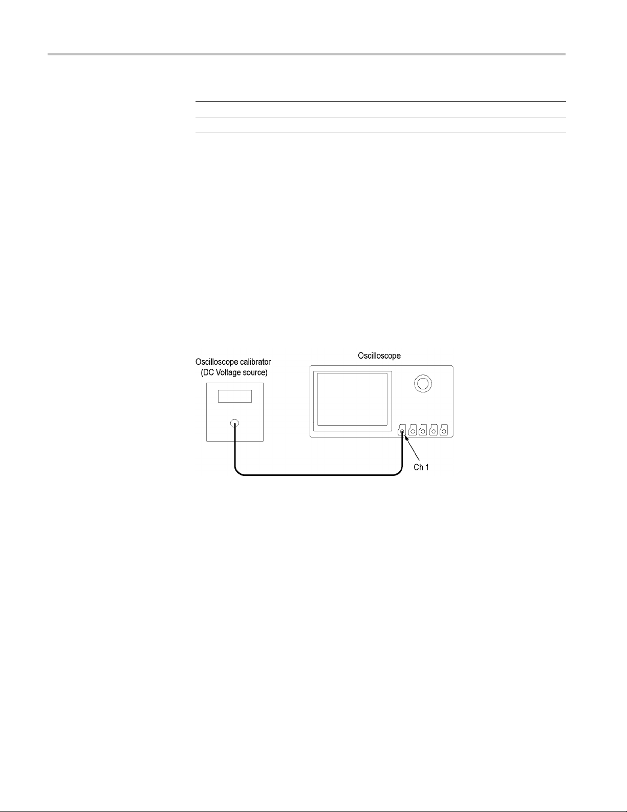
4. Set the DC voltage source to 0 V, and then connect it to channel 1, as shown.
If using a Fluke 9500 as the voltage source, connect the calibrator head to
channel 1.
s the DC Gain Accuracy of each channel.
ngs.
ton, and then push the side-bezel Averag e button, to turn
DPO2000 and MSO2000 Series Specifications and Performance Verification 2–9

Performance Verification
5. Push the front p
anel button to select the channel to be tested (1, 2, 3, or 4)
6. Push the bottom-bezel Probe Setup button, and then push the Set to 1X
side-bezel bu
tton.
7. PushtheWaveInspectorMeasure button, and then push the bottom-bezel
Add Measure
ment button.
8. Use Multipurpose knob a to select the Mean measurement, then push the
side-bezel
OK Add Measurement button, and then push the Menu Off
button.
9. For each Vo
lts/div line in the following worksheet, perform these steps:
a. Set the DC voltage source output level to the positive voltage listed and
record th
e Mean measurement as V
pos
.
b. Set the DC voltage source to the negative level listed, and record the
Mean mea
c. Calculate V
exampl
e, on the 5 mV/div setting, if V
mV, then V
d. Enter
V
diff
surement as V
=V
diff
pos–Vneg
is 34.6 mV.
diff
in the worksheet, and in the test record.
.
neg
, and then enter V
pos
in the test record. As an
diff
is 17.4 mV and V
is -17.2
neg
Table 2-1: DC Gain Accuracy Worksheet
Volts/ div
setting Positive Negative V
Channel 1
5 mV/div
200 mV/div
2V/div
Channel 2
5 mV/div
200 mV/div
2V/div
1
Channel 3
5 mV/div
200 mV/div
2V/div
1
Channel 4
5 mV/div
200 mV/div
2V/div
1
Channels 3 and 4 are only on four channel oscilloscopes.
DC voltage source setting
+17.5 mV –17.5 mV 33.6 mV to 36.4 mV
+700 mV –700 mV 1.358 V to 1.442 V
+7.00 V –7.00 V 13.58 V to 14.42 V
+17.5 mV –17.5 mV 33.6 mV to 36.4 mV
+700 mV –700 mV 1.358 V to 1.442 V
+7.00 V –7.00 V 13.58 V to 14.42 V
+17.5 mV –17.5 mV 33.6 mV to 36.4 mV
+700 mV –700 mV 1.358 V to 1.442 V
+7.00 V –7.00 V 13.58 V to 14.42 V
+17.5 mV –17.5 mV 33.6 mV to 36.4 mV
+700 mV –700 mV 1.358 V to 1.442 V
+7.00 V –7.00 V 13.58 V to 14.42 V
10. Set the DC voltage source to 0 V, and move the BNC cable to the next
channel to be tested.
11. Repeat steps 5 through 10 for each remaining channel.
pos
Accuracy limits
V
neg
V
diff
for V
diff
2–10 DPO2000 and MSO2000 Series Specifications and Performance Verification
Performance Verification
Check Bandwidth
This test check
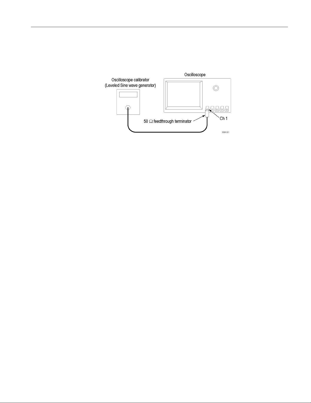
1. Connect the output of the leveled sine wave generator (for example, Fluke
9500) to the os
2. Push the f
default settings.
3. Push the
4. Push the lower-bezel Coupling button, and then push the Noise Reject (DC
Low Sen
5. Push the front-panel Trigger Menu button.
s the bandwidth of all input channels.
cilloscope channel 1 input as shown below.
ront-panel Default Setup button to set the instrument to the factory
front-panel Trigger Menu button.
sitivity) side-bezel button.
6. Push the lower-bezel Source button and use Multipurpose knob a to select the
channel being tested as the trigger source.
7. Push the Menu Off button, so you can see the screen.
8. Push the channel button (1, 2, 3, or 4) for the channel that you want to check.
9. Push the lower-bezel Probe Setup button, and then push the Setto1X
side-bezel button.
10. Push the front-panel Measure button, and then push the bottom-bezel Add
Measurement button.
11. Use Multipurpose knob a to select the Peak-to-peak measurement, and then
push the OK Add Measurement side-bezel button.
12. Turn the Vertical Scale knob to set the vertical scale to 500 mV/div.
13. Turn the Horizontal Scale knob to 400 μs/div.
14. Set the leveled sine wave generator frequency to 1kHz.
15. Set the leveled sine wave generator output level so the peak-to-peak
measurement is between 2.98 V and 3.02 V.
16. Set the leveled sine wave generator to the frequency shown for the
oscilloscope model:
DPO2000 and MSO2000 Series Specifications and Performance Verification 2–11
Performance Verification
Model Frequency
DPO2024, MSO2
DPO2012, DPO2
024
014, MSO2012, MSO2014
200 MHz
100 MHz
17. Use the Horizontal Scale knob to set the oscilloscope to 10 ns/div.
18. Check that the peak-to-peak measurement is ≥2.12 V. Enter this measurement
in the test record.
19. Move the input cable to the next channel to be tested.
20. Repeat steps 5 through 19 for each remaining channel.
Check Vertical Position
Range
This test checks the offset range for each channel.
1. Connect the oscilloscope to a DC voltage source to run this test. If using the
Fluke calibrator as the DC voltage source, connect the calibrator head to the
oscilloscope channel to test.
2. Push the front-panel Default Setup button to set the instrument to the factory
default settings.
3. Push the channel button (1, 2, 3, or 4) for the channel that you want to check.
4. Push the bottom-bezel Probe Setup button, and then push the Set to 1 X
side-bezel button.
5. Use the Vertical Scale knob to set the oscilloscope to 200 mV/div.
6. Use the Vertical Position knob to place the trace at the bottom of the display
(-4 divisions).
7. Set the Offset to +1 V:
a. Push the bottom-bezel More button to select Offset.
b. Use Multipurpose knob a to set the offset to 1.000 V.
8. Set the DC Voltage source to +1.800 V.
2–12 DPO2000 and MSO2000 Series Specifications and Performance Verification

Performance Verification
9. Check that the v
Record Pass or Fail in the test record.
10. Set the DC Volt
11. Push the Set to 0V side-bezel button.
12. Use the Vertical Position knob to place the trace at the top of the display
(+4 divisions).
13. Use Multipurpose knob a to set the offset to –1.000 V.
14. Set the DC Voltage source to –1.800 V.
15. Check that the vertical trace is now within 0.2 divisions of the Zero volt line.
Record Pass or Fail in the test record.
16. Set the DC Voltage source to 0 V.
17. Push the Set to 0V side-bezel button.
18. Use the
19. Use the Vertical Position knob to place the trace at the bottom of the display
(-4 di
20. Use Multipurpose knob a to set the offset to +25.00 V.
Vertical Scale knob to set the oscilloscope to 5 V/div.
visions).
ertical trace is now within 0.2 divisions of the Zero volt line.
agesourceto0V.
21. Set the DC Voltage source to +45 V.
22. Check that the vertical trace is now within 0.2 divisions of the Zero volt line.
Record Pass or Fail in the test record.
23. Set the DC Voltage source to 0 V.
24. Push the Set to 0V side-bezel button.
25. Use the Vertical Position knob to place the trace at the top of the display
(+4 divisions).
26. Use Multipurpose knob a to set the offset to –25.00 V.
et the DC Voltage source to –45 V.
27.S
28. Check that the vertical trace is now within 0.2 divisions of the Zero volt line.
Record Pass or Fail in the test record.
29. Set the DC Voltage source to 0 V.
30. Push the Set to 0V side-bezel button.
31. Move the DC Voltage source cable to the next channel to be tested.
32. Push the channel button (1, 2, 3, or 4) for the next channel to check.
33. Repeat steps 4 through 32 for each of the remaining channels.
DPO2000 and MSO2000 Series Specifications and Performance Verification 2–13
Performance Verification
Check Sample Rate and
Horizontal Position Time
Accuracy
This test check
s the sample rate and horizontal position time accuracy (time base).
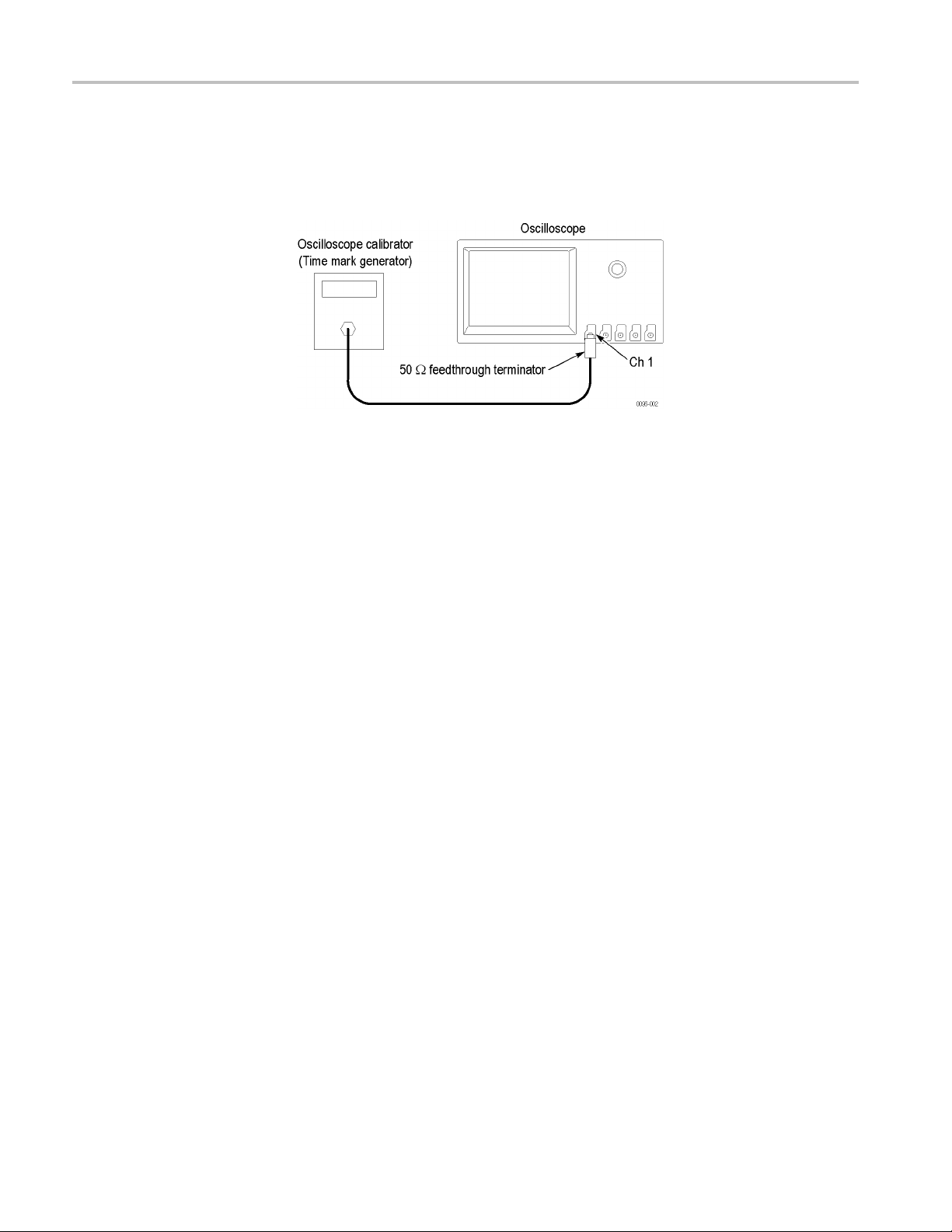
1. Connect the output of the time mark generator to the oscilloscope
channel 1 inpu
tusinga50Ω cable and 50 Ω feedthrough terminator.
2. Set the time mark generator period to 1ms. Use a time ma rk waveform with a
fast rising edge.
3. Push the front-panel Default Setup button to set the instrument to the factory
default settings.
4. Push the channel 1 button.
5. Push th
e lower-bezel Probe Setup button, and then push the Setto1X
side-bezel button.
6. Set th
e Vertical SCALE to 500 mV/div.
7. Set the Horizontal SCALE to 1ms/div.
8. If adjustable, set the time mark generator amplitude to approximately 1V
p-p
9. Push the Trigger Level knob, to set the trigger level to 50%.
10. Adjust the Vertical POSITION knob to center the time mark signal vertically
on the screen.
11. If necessary, adjust the Horizontal POSITION knob to move the trigger
location to the center of the screen (50%).
12. Turn the Horizontal POSITION knob counterclockwise to set the delay to
close to 1ms.
13. Set the Horizontal Scale to 10 ns/div.
14. If necessary, turn the Horizontal Position knob to set the delay to exactly
1.0000 ms.
15. Compare the rising edge of the marker with the center horizontal graticule
line. The rising edge should cross the 0 V center within ±2.5 divisions
(±25 ns) of the center graticule line. Enter the deviation in the test record.
.
2–14 DPO2000 and MSO2000 Series Specifications and Performance Verification
Performance Verification
Check Digital Threshold
Accuracy (MS
O2000 Series
only)
NOTE. One divis
10 ppm time base error.
For the MSO2000 series only, this test checks the threshold accuracy of the digital
channels. T
channel threshold values of 0 V and +4 V.
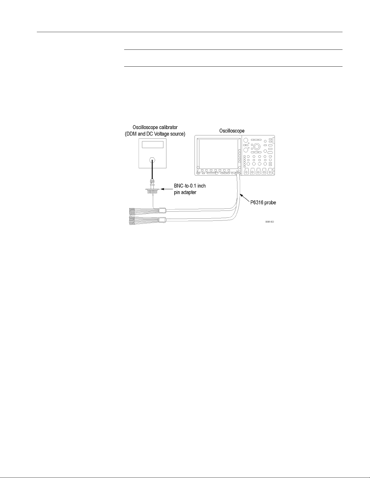
1. Connect the P6316 digital probe to the MSO2000 series instrument.
ion of displacement from graticule center corresponds to a
his procedure applies to digital channels D0 through D15, and to
2. Connect one of the digital channels, such as D0, to the DC voltage source to
run this test.
If using the Fluke calibrator as the DC voltage source, connect the calibrator
head to the digital channel to test. You will need a BNC-to-0.1 inch pin
adapter to complete the connection. Be sure to connect the digital channel to
the corresponding signal pin and to a ground pin on the adapter.
3. Push the front-panel Default Setup button to set the instrument to the factory
default settings.
4. Push the front-panel D15-D0 button.
5. Push the D15-D0 On/Off lower-bezel button.
6. Push the Tu rn On D7 - D0 and the Turn On D15 - D8 side-bezel buttons.
The instrument will display the 16 di
7. Push the Thresholds lower-bezel button.
8. Push the side-bezel D7 - D0 button.
Before you change the threshold value, push the Fine front-panel button to
turn off the fine adjustment and make adjusting the value quicker.
9. Use Multipurpose knob a to set the D7-D0 threshold level to 0V.
gital channels.
10. Use Multipurpose knob b to set the D15-D8 threshold level to 0V.
DPO2000 and MSO2000 Series Specifications and Performance Verification 2–15

Performance Verification
The thresholds
are now set for the 0 V threshold check, shown in steps 11
through 18.
11. Push the front
-panel Trigger Menu button.
12. Push the Source lower-bezel button, and turn Multipurpose knob a to select
the appropr
iate channel, such as D0.
By default, the Type is set to Edge, Coupling is set to DC, Slope is set to
Rising, Mod
e is set to Auto, and Level is set to match the threshold of the
channel being tested.
13. Set the DC v
oltage source (Vs) to -400 mV. Wait 1 second. Check the logic
level of the corresponding digital channel in the display.
If the cha
nnel is a static logic level high, change the DC voltage source Vs
to -500 mV.
14. Increme
ntVsby+10mV.Wait1secondandcheckthelogiclevelofthe
corresponding digital channel in the display. If the channel is at a static logic
level high, record the Vs value as V
in the 0 V row of the test record.
s-
If the channel is a logic level low or is alternating between high and low,
repeat this step (increment Vs by 10 mV, wait 1 second, and check for a static
logic high) until a value for V
is found.
s-
15. Push the Slope lower-bezel button to change the slope to Falling.
16. Set the DC voltage source (Vs) to +400 mV. Wait 1 second. Check the logic
level of the corresponding digital channel in the display.
If the channel is a static logic level low, change the DC voltage source Vs
to +500 mV.
17. Decrement Vs by -10 mV. Wait 1 second and check the logic level of the
corresponding digital channel in the display. If the channel is at a static logic
level low, record the Vs value as V
in the 0 V row of the test record.
s+
If the channel is a logic level high or is alternating between high and low,
repeat this step (decrement Vs by 10 mV, wait 1 second, and check for a static
logic low) until a value for V
18. Find the average, V
=(Vs-+Vs+)/2. Record the average as the test result
sAvg
is found.
s+
in the test record.
Compare the test result to the limits. If the result is between the limits,
continue with the procedure to test the channel at the +4 V threshold value.
19. The remaining part of this procedure is for the +4 V threshold test. Push the
front-panel D15-D0 button. The Thresholds menu should display.
20. With the Fine front-panel button turned off, turn Multipurpose knob a to set
the D7–D0 threshold value to 4.00 V (+4.0 V/div).
2–16 DPO2000 and MSO2000 Series Specifications and Performance Verification

Performance Verification
21. Turn Multipurp
ose knob b to set the D15–D8 threshold value to 4.00 V
(+4.0 V/div). To remove the menu from the display, push the front-panel
Menu Off button.
22. Set the DC voltage source (Vs) to +4.4 V. Wait 1 second. Check the logic
level of the corresponding digital channel in the display.
If the channel is a static logic level low, change the DC voltage source Vs to
+4.5 V.
23. Decrement Vs by -10 mV. Wait 1 second and check the logic level of the
corresponding digital channel in the display. If the channel is at a static logic
level low, record the Vs value as V
in the 4 V row of the test record.
s+
If the channel is a logic level high or is alternating between high and low,
repeat this step (decrement Vs by 10 mV, wait 1 second, and check for a static
logic low) until a value for V
is found.
s+
24. Push the front-panel Trigger Menu button.
25. Push the Slope lower-bezel button to change the slope to Rising.
26. Set the DC voltage source (Vs) to +3.6 V. Wait 1 second. Check the logic
level of the corresponding digital channel in the display.
If the channel is a static logic level high, change the DC voltage source Vs to
+3.5 V.
27. Increment Vs by +10 mV. Wait 1 second and check the logic level of the
corresponding digital channel in the display. If the channel is at a static logic
level high, record the Vs value as V
in the 4 V row of the test record.
s-
If the channel is a logic level low or is alternating between high and low,
repeat this step (increment Vs by 10 mV, wait 1 second, and check for a static
logic high) until a value for V
28. Find the average, V
sAvg
=(Vs-+Vs+)/2. Record the average as the test result
is found.
s-
in the test record.
Compare the test result to the limits. If the result is between the limits, the
channel passes the test.
29. Repeat the procedure starting with step 12 for each remaining digital channel,
D1 through D15.
This completes the performance verification procedure.
DPO2000 and MSO2000 Series Specifications and Performance Verification 2–17
 Loading...