

Page 1

xx
ZZZ
DPO2000 and MSO2000 Series Rackmount Kit
Instructions
Warning
The servicing instructions are for use by qualified personnel
only. To avoid personal injury, do not perform any servicing
unless you are qualified to do so. Refer to all safety summaries
prior to performing service.
www.tektronix.com
P071233200*
*
071-2332-00
Page 2

Copyright © Tektronix. All rights reserved. Licensed software products are owned by Tektronix or its subsidiaries
or suppliers, and are protected by national copyright laws and international treaty provisions.
Tektronix products are covered by U.S. and foreign patents, issued and pending. Information in this publication
supersedes that in all previously published material. Specifications and price change privileges reserved.
TEKTRONIX and TEK are registered trademarks of Tektronix, Inc.
Contacting Tektronix
Tektronix, Inc.
14200 SW Karl Braun Drive
P.O . Bo x 50 0
Beaverto
USA
For product information, sales, service, and technical support:
n, OR 97077
In North America, call 1-800-833-9200.
World wide, visit www.tektronix.com to find contacts in your area.
Page 3

Table of Contents
Service Safety Summary.................................. ................................ ......................... ii
Kit Description....................... .................................. ................................ ............. 1
Products.......... .................................. ................................ ............................. 1
Kit Parts Li
Clearance Requirements ................. .................................. ................................ ... 3
Installation Instructions ............................................................................................ 5
Minimum Tool and Equipment List .............. .................................. ......................... 5
Install....................................... .................................. ................................ ... 6
Rackmount the Rack-Adapted Instrument without rack slides ................ ........................... 9
Rackmou
st .. .................................. ................................ ............................... 1
nt the Rack-Adapted Instrument using rack slides............................................. 10
RMD2000 Rackmount Kit i
Page 4

Service Safety Summary
Service Safet
y Summary
Only qualifie
Safety Summary and the General Safety Summary before performing any service
procedures.
Do Not Service Alone. Do not perform internal service or adjustments of this
product unless another person c apable of rendering first aid and resuscitation is
present.
Disconnect Power. To avoid electric shock, switch off the instrument power, then
disconnect the power cord from the mains power.
Use Care When Servicing With Power On. Dangerous voltages or currents may
exist in
disconnect test leads before removing protective panels, soldering, or replacing
components.
To avoid electric shock, do not touch exposed connections.
d personnel should perform service procedures. Read this Service
this product. Disconnect power, remove battery (if applicable), and
ii RMD2000 Rackmount Kit
Page 5

Kit Description
Products
This introduction describes the rackmount kit for your standard bench-top
instrument.
The rackmount kit is a collection of parts that, once installed, configure the
instrument for mounting into a standard 19-inch equipment rack.
DPO2000 Ser
MSO2000 Se
Kit Parts List
NOTE. The hardware set included in this kit is also used with other kits. Not all of
the hard
Table 1: Kit parts list
Circuit/figure
number Quanti
1-1 1 each 407-5315-xx
-2 1 each 426-2632-xx
-3 1 each 407-5318-xx
-4 1 each 407-5317-xx
-5
-6 2 each 367-0450-xx
t shown
No
Not shown 1 each 016-2006-xx
Not shown 4 each 210-0833-xx
Not shown 4 each 210-1061-xx
Not shown 4 each 210-1546-xx
Not shown 4 each 210-1547-xx
Not shown 4 each 210-1548-xx
Not shown 14 each 211-0507-xx
ty
1 each 407-5316-xx
ach
1e
Part nu
1-2332-00
07
mber
ies
ries
All serial numbers
All serial numbers
ware will be needed.
ption
Descri
ET, BOTTOM
BRACK
LATE, FRONT BRACKET
FACEP
KET, LEFT SIDE
BRAC
CKET, RIGHT SIDE
BRA
CKET, TOP
BRA
NDLE, BOW; CARRYING, 3.75 CTR, 8-32 THD 1.75 H, TG 2000,
HA
SAFETY CONTROLLED
INSTRUCTIONS, TECH:RACKMOUNT, ENGLISH; RMD2000 (this
document)
KIT, HARDWARE RMD2000 — Includes the bow handles (above) and all
he following:
t
WASHER, RECESSED; 0.42 ID X 0.112 THK, STL NI PLATED, 0.588 OD
WASHER, FLAT; 0.203 ID X 0.625 OD X 0.062, 410 SS, PASSIVATE
SCREW, MACHINE, PAN, 8-32 X 1/2 PHIL, SST
LOCKWASHER, #8, SPLIT, .040 THICK
WASHER, FLAT, 12 mm OD X 6.4 mm ID X 1.6 mm THK , STAINLES S
STEEL
SCREW, MACHINE; 6-32 X 0.312, PNH, 410 SS PASSIVATED, POZ
RMD2000 Rackmount Kit 1
Page 6

Kit Description
Table 1 : Kit parts list, (cont.)
Circuit/figure
number Quantity Part number Description
Not shown 4 each 211-0538-xx
Not shown 4 each 211-1218-xx
Not shown 4 each 211-1219-xx
Not shown 4 each 212-0043-xx
Not shown 4 each 212-0591-xx
Not shown 4 each 213-0199-xx
SCREW, MACHINE; 6-32 X 0.312, FLH, 100 DEG, 410 SS PASSIVATED,
POZ
M6 X 16MM PHIL OVAL HEAD, 410 SS, PASSIVATE
SCREW, M5 X 16MM PHIL OVAL, 410 SS, PASSIVATE
SCREW, MACHINE; 8-32 X 0.5, FLH, 100 DEG, 410 SS, POZ
SCREW, MACHINE; 10-32 X 0.75, OVH, POZ, STL, NI
SCREW, MACHINE; 12-24 X 0.75, OVH, STL NP, POZ
Figure 1: Rackmount kit parts
2 RMD2000 Rackmount Kit
Page 7
Kit Description
Table 2: Option
Circuit/figure
number Quantity Part number Description
2-1 1 pair 351-1095-00
Figure 2: Optional accessories
al accessories (must be ordered separately)
SLIDE ASSY; PAIR, W/STD HARDWARE KIT AND REAR BRACKET
NOTE. The rack slides are not part of this kit. They are optional, and must be
ordered separately.
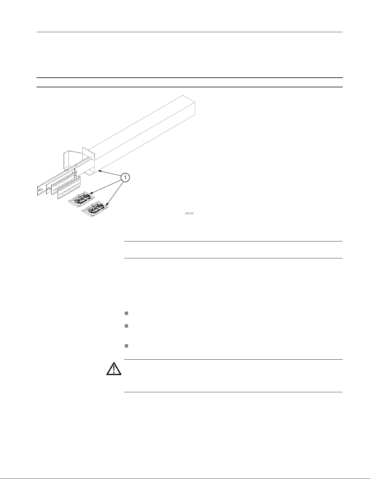
Clearance Requirements
The r
following clearance requirements:
CA
instrument with sufficient clearance for air circulation and accommodation of the
power cord and mounting hardware. Failure to provide these clearances can
result in overheating and can cause instrument faults or failure.
ack in which the rack-adapted instrument is mounted must provide the
imum of 177.80 mm (7.00 in) of vertical space
Amin
A minimum width of 450.10 mm (17.72 in) between the left- and right-front
ls in the rack
rai
A minimum depth of 336.55 mm (13.25 in)
UTION. Adhering to these clearance requirements provides the rack-mounted
RMD2000 Rackmount Kit 3
Page 8
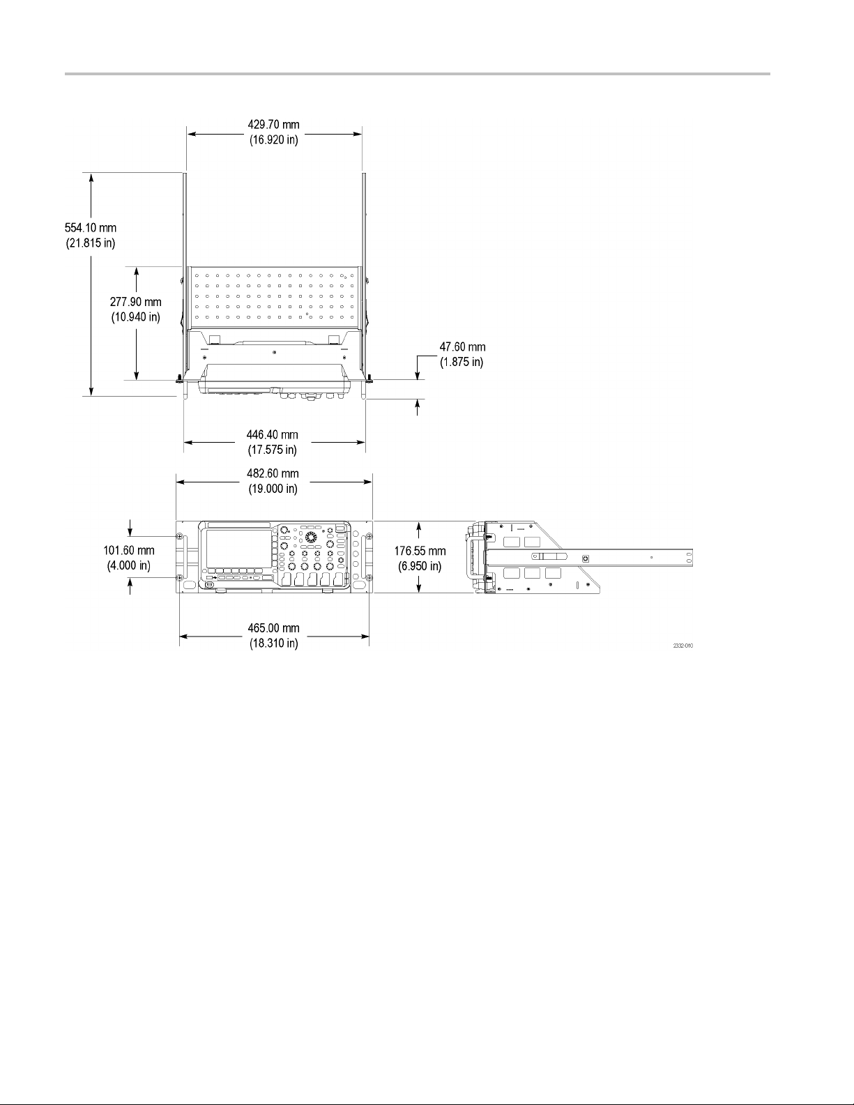
Kit Description
Figure 3: Instrument with rack adapter installed
4 RMD2000 Rackmount Kit
Page 9

Installation Instructions
This section contains the procedures needed to rackmount a DPO2000 or
MSO2000 series instrument.
Minimum Tool and Equipment List
The following tools are required to attach the rack-adapter kit hardware, install
cabling har
equipment cabinet. All tools are standard tools that are readily available.
Table 3: Tools required for rackmount installation
Name Description
Screwdriver handle
(magnetic)
No. 2 Pozidriv or
Phillips tip
Straight tip Straight screwdriver tip for slotted screw heads
1
/4inch wrench
Torque driver
dware, and mount the rack-adapted instrument into a standard
Installation Instructions
Accepts1/4inch hexagonal head driver tips
Pozidriv or-Phillips driver tip for number 2 size screw heads
Wrench or nut driver can be used to install slides
6.5 in long shaft; accepts
1
/4inch hexagonal head driver tips
These instructions are for qualified service personnel who are familiar with
icing the product. If you need further details for disassembling or reassembling
serv
the product, refer to the appropriate product manual. Contact your nearest
Tektronix Service Center or Tektronix Factory Service for installation assistance.
WAR N ING. To prevent the rackmounted instrument from tipping forward onto the
operator, install the instrument so that the operator will be able to access all of its
rear-panel connectors without pushing down on the instrument.
Verify that the rack does not become unstable with the instrument fully extended.
Do not leave the instrument extended when finished accessing the rear panel.
RMD2000 Rackmount Kit 5
Page 10
Installation Instructions
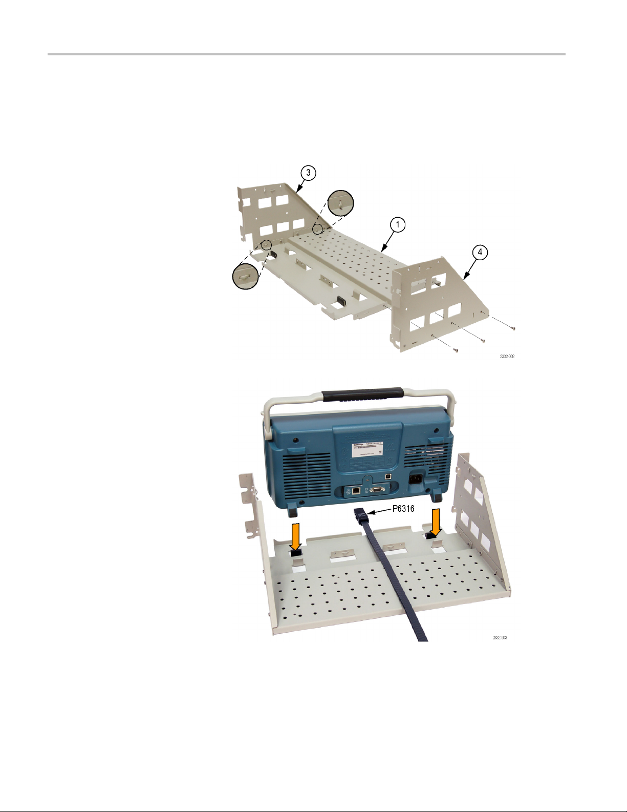
Install
Equipment Required: Torque driver with #2 Pozidriv tip.
This section describes mounting the rackmount adapter parts to the instrument.
1. Install the left and right side brackets
onto the bottom bracket using three of
the 6-32 x 0.312 inch pan head Pozidriv
screws on each side. Tighten these
screws to 8 in-lb.
2. Place the oscilloscope into the
rackmount frame as shown. Position
the oscilloscope’s rear feet in the
brackets. The front of the o scilloscope
will extend slightly beyond the front of
the rackmount frame.
If your application r equires that the
digital probe be routed to the interior of
the rack, place the probe cable(s) in
the slot provided before positioning the
oscilloscope.
6 RMD2000 Rackmount Kit
Page 11
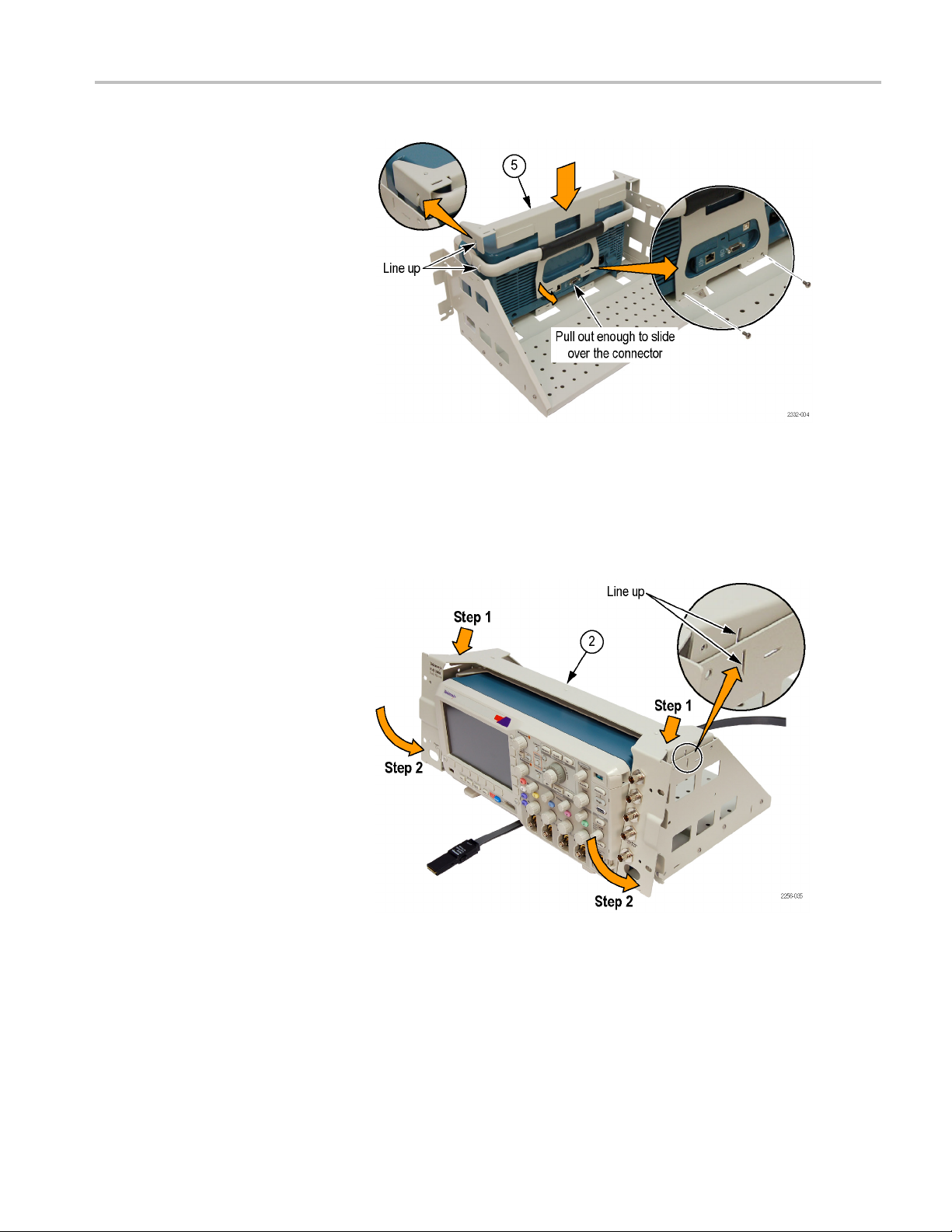
Installation Instructions
3. Place the osci
straight-back position and install the
top bracket, aligning the cutouts in the
bracket as sh
the bottom of the bracket out a little, to
clear the r ear panel connectors, as you
slide the br
Use two of the 6-32 x 0.312 inch pan
head Pozidriv screws to attach the top
bracket to
these screws to 8 in-lb.
For your c
BNC double female bulkhead jacks, also known as bulkhead adapters. If you need them in your installation, install the
adapters now. It is also recommended that you attach the interior cables to the adapters before installing the front panel
bracket,
onvenience there are five holes in the right side of the front panel. These are designed to accommodate
in the next step.
lloscope handle in the
own. You will have to pull
acket into position.
the oscilloscope.Tighten
NOTE. The BNC double female jacks are not included as part of this rackmount kit; they must be purchased separately.
4. Align the guides in the front panel
bracket and the sides, as shown, and
then swing the bottom of the front panel
bracket into position.
RMD2000 Rackmount Kit 7
Page 12

Installation Instructions
5. Attach the front panel bracket to the
sides with three of the 6-32 x 0.312 inch
pan head Pozidriv screws on each side.
Tighten these screws to 8 in-lb.
6. Attach the front panel bracket to the top
bracket with three of the 6-32 X 0.312
flat head Pozidriv screws. Tighten these
screws to 8 in-lb.
7. Attach the handles, using two of the
8-32 x 1/2 panhead screws and split
lockwashers in each handle. Torque
these screws to 16 in-lb.
8 RMD2000 Rackmount Kit
Page 13

NOTE. The bottom bracket has holes to
facilitate mounting optional accessories.
Optional accessories may be mounted with
screws, or you can use nylon straps to
secure them. These screws and nylon straps
are not included in the kit.
Installation Instructions
Rackmount the Rack-Adapted Instrument without rack slides
If you did not order the optional rackmount s lides, you may install the
rack-adapted instrument into an equipment rack by following this procedure:
WAR N ING. To prevent the instrument from tipping or falling onto the installers,
this procedure should be performed by two or more people.
Install Instrument into the
Rack
1. Select the appropriate screws for your
equipment rack from the kit; 10–32, 12–24,
M5, or M6. Assemble them with the
recessed and flat washers as shown:
Equipment Required: One screwdriver handle and one number two Pozidriv tip.
Procedure:
RMD2000 Rackmount Kit 9
Page 14

Installation Instructions
2. Standard equipment racks utilize one
of two mounting hole s pacing methods.
Both methods u
0.5 inch apart, separated by a 1.25 inch
gap. One method (A) places an additional
mounting hole
inch gap (at 0.625, or 5/8, inch); the other
method (B) does not.
3. Select two 0.
front rail. Verify that there are clearances
of 1.5 inch above the upper mounting hole
and 5.50 inc
hole.
4. Slide the oscilloscope into the equipment
rack so tha
from the left side, just below the upper
mounting hole, goes into the lower of the
0.5 inch-s
pin is a locating guide, and also an aid
to holding the oscilloscope in place while
securing
rack.
5. Use the screws and washers from step 1 to
secure t
rack.
se mounting holes spaced
in the middle of the 1.25
5 inch-spaced holes in the
h below the lower mounting
t the pin extending back
paced holes in the front rail. This
the oscilloscope to the instrument
he oscilloscope to the instrument
Rackmount the Rack-Adapted Instrument using rack slides
If you ordered the optional rackmount slides, this procedure assembles and installs
the slide-out tracks in the equipment rack, and then installs the rack-adapted
instrument in the rack.
The slide-out tracks permit the rack-adapted instrument to be extended out of the
rack for rear-panel and connector maintenance without removing the instrument
from the rack.
10 RMD2000 Rackmount Kit
Page 15
Installation Instructions
WAR N ING. To prevent the rackmounted instrument from tipping forward onto the
operator, ins
tall the instrument so that the operator will be able to access all of its
rear devices without pushing down on the instrument.
Verify that t
Do not leave the instrument extended when finished accessing the rear panel.
Install Track Assembly and
Instrument into the Rack
Equipment
straight slot tip, one
NOTE. The rack hardware kit contains hardware for mounting the instrument in
several configurations. Not all of the hardware in the kit will be needed.
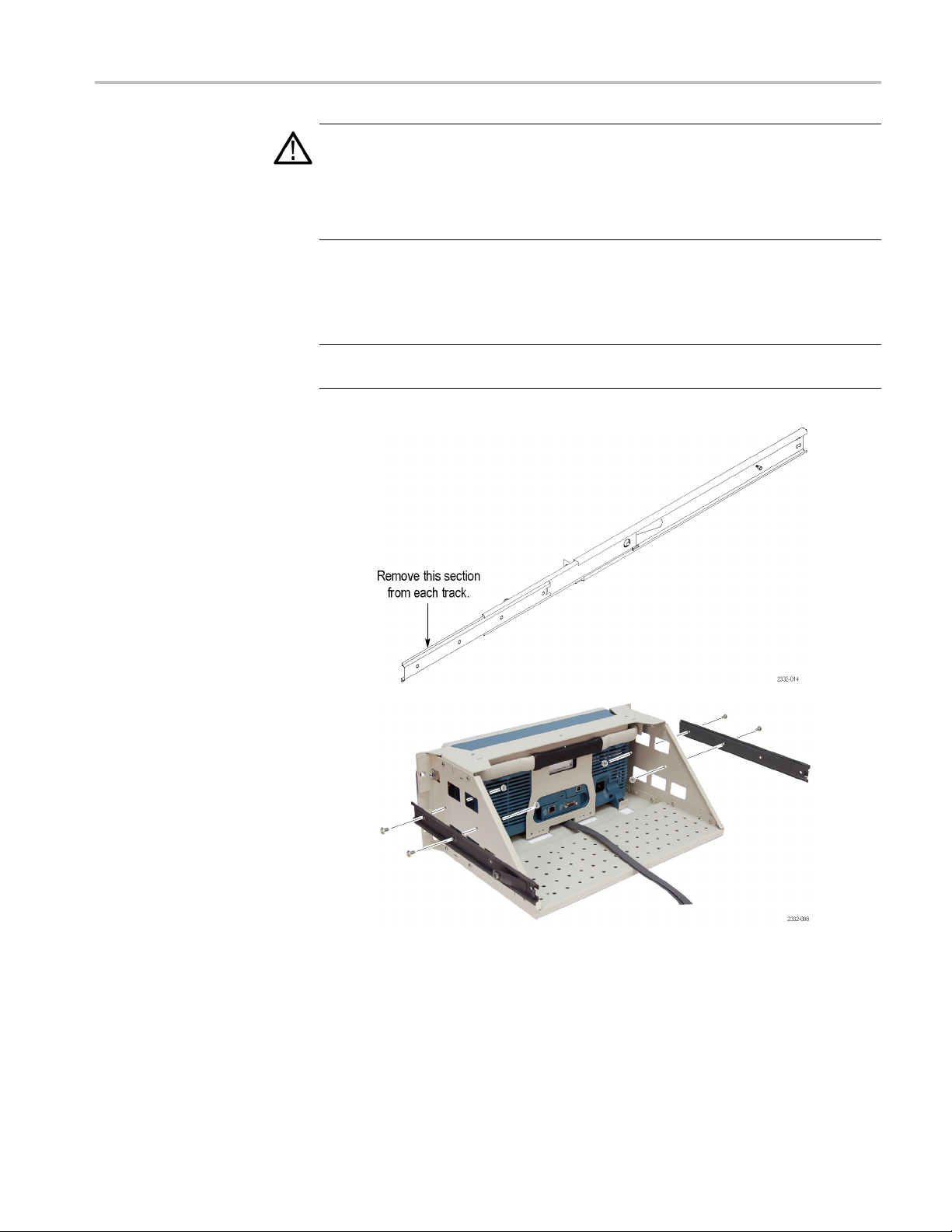
Attach the front (chassis) left and right
tracks to the rack adapter:
1. Remove the front (chassis) section of each
of the two tracks.
he rack does not become unstable with the instrument fully extended.
Required: One screwdriver handle, one number two Pozidriv tip, one
1
/4inch wrench, and one torque driver.
tall the front left- and right-side track
2. Ins
sections on the instrument using four of
the 10-32 x 3/8 inch slotted screws and the
s with captured lockwashers. Tighten
nut
to 28 in-lb.
RMD2000 Rackmount Kit 11
Page 16

Installation Instructions
WARNING. To ensure that the rackmount
track locks,
are oriented correctly: the right-side latch is
located toward the bottom of the rackmount
panel and th
the top of the rackmount panel.
Assemble the slide-out track:
3. Measure the distance between the front
4. Align the
5. Using a screwdriver with a number two
6. Step-
make sure the track button latches
e left-side latch is located toward
and rear rail of the equipment rack.
rear bracket to the right slide-out
track as shown. Note that the rear bracket
has multiple pairs of mount-through holes.
When ali
sure to select a pair of holes that mount the
rear bracket so that the flange-to-flange
distan
front rail and rear rail measured in step 3.
Pozidr
the right slide-out track using two screws
(10-32) and a bar nut as illustrated. Leave
the sc
of the slide-out track assembly can be
adjusted when installing it in the rack.
the left slide-out track assembly.
gning the bracket and track, be
ce matches the distance between the
iv tip, secure the rear bracket to
rews loose so that the overall length
Repeat steps 4 and 5 to assemble
12 RMD2000 Rackmount Kit
Page 17

Mount the slide-out track assemblies:
7. Select the mounting position in the rack:
Select two 0.5 inch-spaced holes in the
front rail, and verify that there is a 3.25
inch clearance above and below those
mounting holes.
Installation Instructions
RMD2000 Rackmount Kit 13
Page 18
Installation Instructions
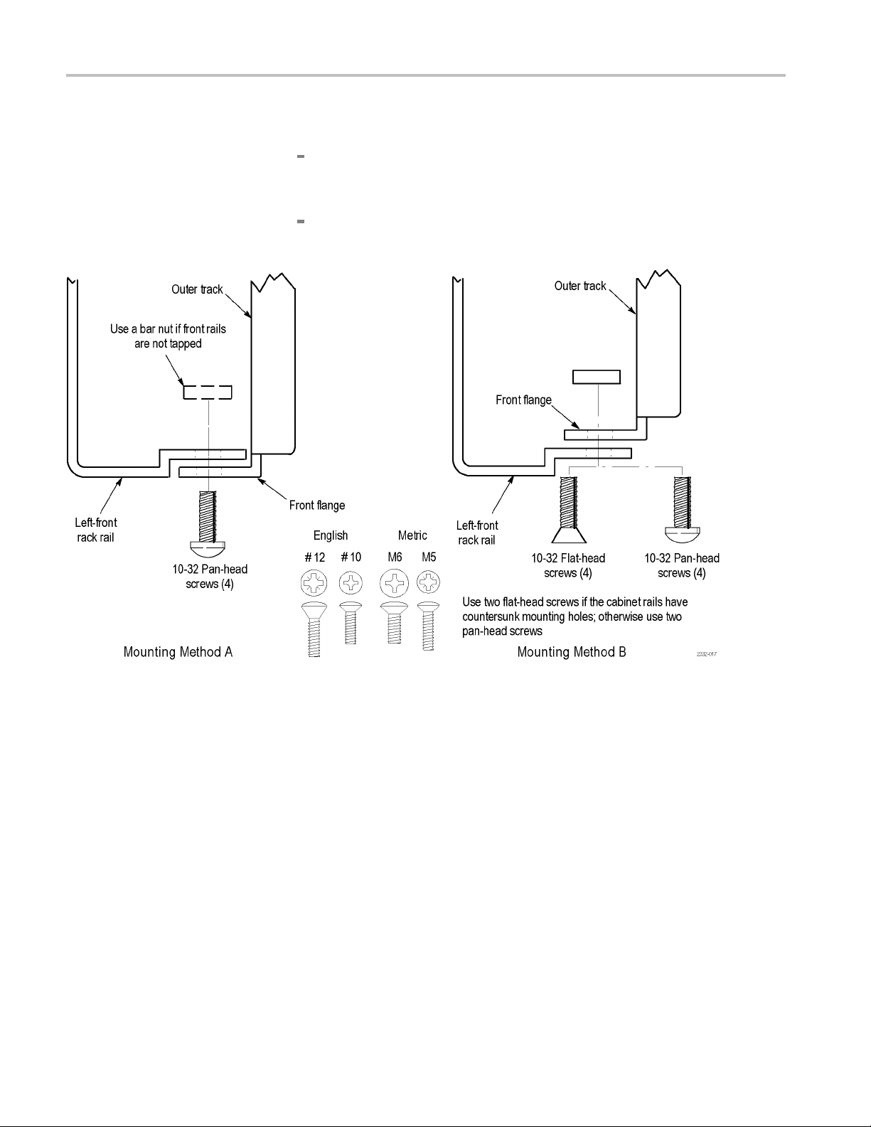
8. Select the moun
To mount the slide-out tracks with their front and rear flanges outside of
the front and r
bar nut to the installation only if the rails have untapped holes.
To mount wit
method B. (See Figure 4.) This mounting method assumes untapped holes.
ting method according to the rack type:
ear rails, use the mounting method A. (See Figure 4.) Add a
h front and rear flanges inside of rails, use the mounting
Figure 4: Installation of slide-out track assemblies in rack (top view)
9. Install in rack: Using the method and hardware determined in step 8, secure
the right slide-out track assembly to its front and rear rails. The screws should
be fully, but lightly, seated so mounting can be adjusted later.
10. Fix the length of the slide-out track assembly: Tighten the screws left loose
instep5to28inch-lb,tofix the front to rear flange spacing of the slide-out
ack assembly.
tr
11. Mount the left slide-out track assembly: Repeat steps 9 and 10 to mount the
eft slide-out track assembly.
l
14 RMD2000 Rackmount Kit
Page 19

Installation Instructions
Mount the instr
ument in
the rack:
WAR N ING. To prevent the instrument from tipping or falling onto the installers,
twoormorepe
After completing the installation procedure, the installers should verify that the
instrument and rack cabinet will not tip forward while the instrument is in the
extended position.
1. Install the instrument:
a. Working f r
track assembly until it extends out the front of the rack. Continue to slide
them out until they lock.
b. Insert the left and right tracks that extend from the rear of the instrument
into the ends of the tracks just extended. Make sure the tracks mounted on
the instrument slip inside the inner tracks extended earlier.
c. Slide the instrument backwards until it stops.
d. Push to release the button latches, located on the outside of each track,
and continue to slide the instrument all the way into the cabinet.
ople should install this instrument into the rack cabinet.
om the front of the rack, slide the inner track of each slide-out
2. Level the rackmounted instrument:
a. Tigh
b. Be s
c. Retighten the four screws and push the instrument all the way into the
d. When leveling is completed, tighten the 10-32 screws using 28 inch-lb of
ten the four screws that were left loose at the rear of the rack when
you did step 5, and then pull the instrument part way out of the rack.
ure that the four screws that were left loose at the front of the rack
are loose enough to allow the slide-out track assemblies to seek their
normal positions.
rack. If the tracks do not slide smoothly, readjust the level using the
method just detailed.
torque.
RMD2000 Rackmount Kit 15
Page 20

Installation Instructions
Finishing the Installation
It is recommend
ed that you secure the instrument to the rack.
WARNING. To prevent the rackm ounted instrument from sliding forward and
causing personal injury or instrument damage, always secure the instrument to
therackifthe
rack is moved (for example, if the rack is repositioned or relocated
to another room).
3. Secure the instrument to the rack:
a. Select four of the appropriate screws for your equipment rack from the
kit; 10-32, 12-24, M5, or M6.
b. Secure the instrument in the rack using the screws selected, with the
recessed washers and flat washers.
End of Document
16 RMD2000 Rackmount Kit
 Loading...