


xx
ZZZ
DPO2000 and MSO2000 Series Oscilloscopes
Service Manual
*P071233100*
071-2331-00


xx
ZZZ
DPO2000 and MSO2000 Series Oscilloscopes
Service Manual
Revision B
www.tektronix.com
071-2331-00

Copyright © Tektronix. All rights reserved. Licensed software products are owned by Tektronix or its subsidiaries
or suppliers, and are protected by national copyright laws and international treaty provisions.
Tektronix products are c overed by U.S. and foreign patents, issued and pending. Information in this publication
supersedes that in all previously published material. Specifications and price change privileges reserved.
TEKTRONIX and TEK are registered trademarks of Tektronix, Inc.
Tektronix is an authorized licensee of the CompactFlash® trademark.
Contacting Tektronix
Tektronix, Inc.
14150 SW Karl Braun Drive
P.O. B o x 5 0 0
Beaverton, OR 97077
USA
For product information, sales, service, and technical support:
In North America, call 1-800-833-9200.
Worl dwid e, v isit www.tektronix.com to find contacts in your area.

Table of Contents
General safety summary ............................................ ................................ .............. iv
Service safety summary........................................................................................... vi
Preface............................................................................................................. vii
Manual Conv
Related Documentation ..................................................................................... vii
Operating Information ............................................................................................. 1
Theory of Operation....................... ................................ ................................ ......... 3
Block Diagram........ ................................ ................................ ......................... 3
Power Supply................................................................................................... 4
Front En
Main Board ..................................................................................................... 4
Front-Panel Board .......................................... .................................. ................. 4
Adjustment Procedures ............................................................................................ 5
Required Equipment........................ ................................ ................................ ... 5
Overview of the Adjustment Process ........................................................................ 6
ory Adjustment Procedure ............................................................................... 7
Fact
Completing the Procedure ................................. ................................ ................... 9
Maintenance........................................................................................................ 13
Preventing ESD ............................................................................................... 13
Inspection and Cleaning.. .................................. ................................ .................. 13
Overview of Removal Procedures ...... ................................ ................................ .... 17
moval Procedures.......................................................................................... 18
Re
Troubleshooting..................................... ................................ .......................... 24
Troubleshooting Procedure .... ................................ ................................ .............. 25
Unpacking and Repacking Instructions .................. ................................ .................. 27
Replaceable Parts List............................. ................................ ................................ 29
Parts Ordering Information .................................................................................. 29
Using the Replaceable Parts List............................................................................ 30
entions.......... .................................. ................................ ............. vii
d Assembly........................................................................................... 4
DPO2000 and MSO2000 Series Service Manual i

Table of Contents
List of Figure
Figure 1: Oscilloscope module interconnections .... . ..... . ..... . . .... . . ..... . ..... . ..... . ..... . ..... . ...... . .. 3
Figure 2: Lo
Figure 3: Primary troubleshooting procedure .................................................................. 25
Figure 4: AC power supply troubleshooting procedure ....................................................... 26
Figure 5: Module isolation troubleshooting procedure........................................................ 27
Figure 6: Front trim ....................... ................................ ................................ ........ 31
Figure 7: Rear trim ...... ................................ ................................ .......................... 32
Figure 8:
Figure 9: Power supply ........................................................................................... 34
Figure 10: Rear chassis ........................................................................................... 35
Figure 11: Fan ..................................................................................................... 36
Figure 12: Main board .......... ................................ .................................. ................ 37
Figure 13: Front end assembly................................................................................... 38
e 14: Main chassis..................................... ................................ ...................... 39
Figur
Figure 15: Display............................. .................................. ................................ .. 40
Figure 16: Front panel board......................... .................................. .......................... 41
Figure 17: Option key guides .................................................................................... 42
cator for internal modules.............................................. ............................ 18
Rear case ........................ ................................ .................................. ...... 33
s
ii DPO2000 and MSO2000 Series Service Manual

List of Tables
Table i: Related documentation................................................................................. vii
Table 1: Ext
Table 2: Internal inspection check list................................... ................................ ........ 16
Table 3: Front trim ............ ................................ .................................. .................. 31
Table 4: Rear trim ................... ................................ .................................. ............ 32
Table 5: Rear case ............................... ................................ .................................. 33
Table 6: Power supply ................ ................................ ................................ ............ 34
Table 7 : R
Table 8: Fan .......... ................................ .................................. ............................ 36
Table 9: Main board............................................................................................... 37
Table 10: Front end board ........ ................................ .................................. .............. 38
Table 11: Main chassis............................................................................................ 39
Table 12: Display.................................................................................................. 40
Table
Table 14: Option key guides ....... ................................ .................................. ............ 42
Table 15: Replaceable parts list: DPO2000 and MSO2000 Accessories.................................... 43
ernal inspection check list.......................................................................... 15
ear chassis.................................. ................................ ............................ 35
13: Front panel board ................ .................................. ................................ .... 41
Table of Contents
DPO2000 and MSO2000 Series Service Manual iii

General safety summary
General safet
To avoid fir
e or personal
injury
ysummary
Review the fo
this product or any products connected to it.
To avoid pot
Only qualified personnel should perform service procedures.
Use proper
certified for the country of use.
Connect a
leads while they are connected to a voltage source.
Ground th
of the power cord. To avoid electric shock, the grounding conductor must be
connected to earth ground. Before making connections to the input or output
terminals of the product, ensure that the product is properly grounded.
Observe all terminal ratings. To avoid fire or shock hazard, observe all ratings
and markings on the product. Consult the product manual for further ratings
information before making connections to the product.
llowing safety precautions to avoid injury and prevent damage to
ential hazards, use this product o nly as specified.
power cord. Use only the power cord specified for this product and
nd disconnect properly. Do not connect or disconnect probes or test
eproduct.This product is grounded through the grounding conductor
Connect the probe reference lead to earth ground only.
Do not apply a potential to any terminal, including the common terminal, that
exceeds the maximum rating of that terminal.
Power disconnect. The power cord disconnects the product from the power source.
Donotblockthepowercord;itmustremain accessible to the user at all times.
Do not operate without covers. Do not operate this product with covers or panels
removed.
Do not operate with suspected failures. If you suspect that there is damage to this
product, have it inspected by qualified service per sonnel.
Avoid exposed circuitry. Do not touch exposed connections and components when
power is present.
Do not operate in wet/damp conditions.
Do not operate in an explosive atmosphere.
Keep product surfaces clean and dry.
Provide proper ventilation. Refer to the manual's installation instructions for details
on installing the product s o it has proper ventilation.
iv DPO2000 and MSO2000 Series Service Manual

General safety summary
Terms in this m anual
Symbols and terms on the
product
These terms may
WAR NI NG . Warning statements identify conditions or practices that could result
in injury or loss of life.
CAUTION. Caution statements identify conditions or practices that could result in
damage to this product or other property.
These terms may appear on the product:
DANGER in
the marking.
WARNING
read the marking.
CAUTIO
The following symbol(s) may appear on the product:
appear in this manual:
dicates an injury hazard immediately accessible as you read
indicates an injury hazard not immediately accessible as you
N indicates a hazard to property including the product.
DPO2000 and MSO2000 Series Service Manual v

Service s afety summary
Service safet
ysummary
Only qualifie
safety summary and the General safety summary before performing any service
procedures.
Do not service alone. Do not perform internal service or adjustments of this
product unless another person capable of rendering first aid and resuscitation is
present.
Disconnect power. To avoid electric shock, switch off the instrument power, then
disconnect the power cord from the mains power.
Use care when servicing with power on. Dangerous voltages or currents may exist
in this p
test leads before removing protective panels, soldering, or replacing components.
To avoi
d personnel should perform service procedures. Read this Service
roduct. Disconnect power, remove battery (if applicable), and disconnect
d electric shock, do not touch exposed connections.
vi DPO2000 and MSO2000 Series Service Manual

Preface
Manual Conventions
This service manual provides information that you need to troubleshoot,
disassemble, and replace parts on the Tektronix DPO2000 and MSO2000 Series
Oscilloscop
es.
l uses certain conventions that you should become familiar with
erm module.
eable part is any circuit board or assembly, such as the power supply, or a
ols and terms related to safety appear in the General Safety Summary
Modules
Replaceable Parts
Safety
This manua
before attempting service.
Throughout this manual, any replaceable component, assembly, or part is referred
to by the t
This manual refers to any field-replaceable assembly or mechanical part
specifically by its name or generically as a replaceable part. In general, a
replac
mechanical part, such as the I/O port connectors, that is listed in the replaceable
parts list.
Symb
Related Documentation
Table i: Related documentation
To read about Use these documents
Installation and Operation DPO2000 and MSO2000 Series Digital Phosphor Oscilloscopes User Manual (available in
11 languages)
Specifications and Performance DPO2000 and MSO2000 Series Specifications and Performance Verification Technical
Reference (PDF only)
Programmer Commands DPO2000 and MSO2000 Series Programmer Manual (PDF only)
Analysis and Connectivity Tools Getting Started with OpenChoice® Solutions Manual
Installing and testing applications
modules
Oscilloscope calibrator Fluke Oscilloscope Calibrator Manual at http://us.fluke.com
DPO2000 and MSO2000 Series Application Modules Installation Instructions Manual
The Tektronix manuals are available on the Web, at www.tektronix.com/manuals.
DPO2000 and MSO2000 Series Service Manual vii

Preface
viii DPO2000 and MSO2000 Series Service Manual

Operating Information
For information on installing and operating your DPO2000 or your MSO2000
Series Oscilloscope, refer to the DPO2000 and MSO2000 Series Oscilloscopes
User Manual.
The User manual is available, in 11 languages, on the Web at www.tektronix.com.
DPO2000 and MSO2000 Series Service Manual 1

Operating Information
2 DPO2000 and MSO2000 Series Service Manual

Theory of Operation
This chapter describes the electrical operation of the oscilloscope to the module
level. Figure 2-1 shows the oscilloscope module interconnections.
Block Diagram
Figure 1: Oscilloscope module interconnections
DPO2000 and MSO2000 Series Service Manual 3

Theory of Operation
Power Supply
Front End Assembly
The Power Supply board converts AC line voltage to +3.3 V, +5 V, –5 V, and
+13 V to power all internal circuits. The Power Supply board also supplies power
to the displa
y backlight.
Main Board
Acquisition System
Trigger System
Display System
The Front E
differential mode channel signals which are passed to the Main board. The analog
inputs, attenuators, and preamps are contained in this assembly.
The Main board module contains the following functions:
The Acq
from the Front End assembly, which are routed to the A/D inputs, and ends with
a digitized signal in memory.
The Tr
trigger functions are enabled only when the appropriate application modules and
supporting software are installed.
The D
menus and text, and stores this information in display memory. It then uses this
data to refresh the WQVGA display module (LCD).
nd assembly begins with the analog signal path and ends with
uisition system begins by accepting the differential mode channel signals
igger system processes the digitized signal stored in memory. Advanced
isplay system combines live waveform data from acquisition memory with
e Processor system contains a Power PC microprocessor that controls the entire
Processor System
Th
instrument. The processor system also contains FLASH ROM, system RAM, and
interfaces to Ethernet and to the USB ports.
Front-Panel Board
The Front Panel board contains a microprocessor that reads the front-panel buttons
and controls, and then sends this information to the processor system on the Main
board. The Front Panel board also generates the probe compensation output signal
and provides an interface to the application modules.
4 DPO2000 and MSO2000 Series Service Manual

Adjustment Procedures
This chapter contains the factory adjustment procedure for the DPO2000 Series
and the MSO2000 Series oscilloscopes. Only qualified personnel should perform
adjustment procedures. Read the Service Safety Summary and the General Safety
Summary before performing any service procedures.
Required Equipment
NOTE. The vo
ltage references inside the oscilloscope are very stable over time
and should not require routine adjustment. Before performing any procedure
in this chapter, do the Performance Verification procedures to check whether
the oscilloscope meets specifications. See the DPO2000 and MSO2000 Series
Specification and Performance Verification Technical Reference.
Successful completion of this adjustment procedure automatically updates the
stored time and date of the latest successful adjustment. Completion of the
Performance Verification procedure does not update this date and time. If no
adjustm
ent is needed, there is also no need to update the time and date of the
adjustment.
The following equipment, or a suitable equivalent, is required to complete these
procedures.
The following table specifies required equipment for the MSO2000 Series
oscilloscope.
cription
Des
oltage source
DC v
gital calibrator probe
Di
BNC to square pin adapter Connects signal from BNC
imum requiremen ts
Min
to 25 V, ±0.1%
5mV
amplitude accuracy
ecision test probe, 16
Pr
digital channels
to 16 square pins
mple
Exa
Fluke or Wavetek 9500
illoscope Calibrator with
Osc
five 9530 active heads.
ktronix Part Number
Te
067-6316-00
ktronix Part Number
Te
878-0219-00
The following table specifies required equipment for the DPO2000 Series
scilloscope.
o
DPO2000 and MSO2000 Series Service Manual 5

Adjustment Procedures
Description Minimum requir
DC voltage sou
Sine Generator
Edge G enerator
50 Ω BNC cable BNC male to BNC male,
rce
Overview of the Adjustment Process
Before pe
for at least 20 minutes in an ambient temperature between 20 °C and 30 °C.
Adjustments performed before warm-up or outside this temperature range may
result in poor performance or calibration failure.
The factory adjustment procedure consists of a series of steps; as you move
through these steps, the oscilloscope display provides instructions that describe
the specific input signal requirements for each step. If the oscilloscope passes the
step, it moves on to the next step. If the oscilloscope fails, you can repeat the
step o
rforming adjustment procedures, you must warm up the oscilloscope
r choose to abort the procedure.
ements
5mVto25V,±0.
amplitude accuracy
1 kHz to 200 MHz
1 kHz with < 50
skew
about 10 in (25 cm) long
1%
ps ch-ch
Example
Fluke or Wavetek 9500
Oscilloscope
9530 active heads
Wavetek 9500 Oscilloscope
Calibrator with one 9510
Output Modul
Tektronix p
012-0208-00
Calibrator with
e
art number
If you have difficulty completing the steps, refer to the Completing the Procedure
ion for specific instructions and troubleshooting information.
sect
To complete the calibration procedure, you must know how to operate the
lloscope calibrator. Please refer to the user manual, which can be found at
osci
http://us.fluke.com.
NOTE. Do not turn any knobs or push any front-panel buttons other than the Next
Step or Previous Step buttons during the adjustment procedure. Doing so will
cause the oscilloscope to abort the adjustment procedure. The oscilloscope uses
the previous calibration constants if the adjustment procedure is aborted or fails.
The screen does not display the signal traces or actual oscilloscope settings
(such as channel input impedance, or vertical and horizontal settings) during
the adjustment procedure. The oscillosc ope automatically sets the instrument
settings, but these settings may not read out correctly on the display.
During some steps, the instrument may appear to be idle for several minutes while
it is processing information internally.
6 DPO2000 and MSO2000 Series Service Manual

Adjustment Procedures
Factory Adj
If the oscillos
message is displayed and the new calibration constants take effect. If the
oscilloscope does not pass a step, you can repeat the step. To cancel the calibration
procedure, press the Menu Off front panel button on the oscilloscope. This
reverts the oscilloscope to the old calibration constants.
ustment Procedure
To perform the factory adjustment procedure, complete these steps:
1. Connect the oscilloscope to an AC power source.
NOTE. You must connect the oscilloscope and the test equipment to the same
AC power circuit. Connect the oscilloscope and test instruments to a common
power st
oscilloscope and test instruments to separate AC power circuits can result in offset
voltages between the equipment, which can invalidate the adjustment procedure.
2. Power on the oscilloscope and warm it up for 20 minutes.
3. Power
rip if you are unsure of the AC power circuit distribution. Connecting the
cope completes all steps in the procedure successfully, a "Pass"
on the oscilloscope calibrator and warm it up for 20 minutes.
4. Connect the active heads from the calibrator to the oscilloscope, ensuring
Channel 1 on the calibrator connects to Channel 1 on the oscilloscope,
that
and so on.
NOTE. For the DPO2000, there will be either 2 or 4 channels to connect. For
the MSO2000, there will be either 2 or 4 channels to connect, plus an additional
channel connection for the digital probe. Plug the digital probe into the Channel
5 active head on the calibrator, using the BNC to square pin adapter, but do not
ug the probe into the oscilloscope until you are directed to by the c alibration
pl
process. Once you do plug the digital probe into the oscilloscope, do not unplug it
until the adjustment procedure is completed.
5. Access the Factory Adjustment menu:
a. Press the front-panel Utility button, and then press the bottom-bezel
Utility Page button.
b. Use Multipurpose knob a to select Calibration, and then press the
bottom-bezel Factory button. The Factory adjustment passed dialog will
appear, as shown below.
DPO2000 and MSO2000 Series Service Manual 7

Adjustment Procedures
c. While the dialog window is open, press and hold the top side-bezel button
(below the Waveform Only button) for approximately five seconds. The
Factory A
djustment description and menu will appear, as shown here.
d. Push the OK Do Factory Adjustment side-bezel button to start the
adjustment process. Prompts appear on the oscilloscope screen to indicate
ignal type and the channels to which it should be connected.
the s
NOTE. The oscilloscope adjusts itself automatically using the calibrator
signal as a reference. You do not need to make any adjustments.
If you make an error, such as connecting the wrong input signal, you can
repeat the last step by pushing the Return to Previous Screen side bezel
button.
6. For each step, refer to the following table to identify the signal type, and then
carefully follow the instructions for that signal type on the specified page.
8 DPO2000 and MSO2000 Series Service Manual

Adjustment Procedures
Signal type Example prompt Refer to Parameters to set
DC Voltage Apply 0 V DC 50 Ω
termination signal
to 3.
Sine Signal
Apply 2.0 V Pk
1MHz50Ω
termination s ine
signal to 3.
-Pk
(See page 10.) Waveform
type, voltage,
termination,
channel
(See page 11.) Waveform type,
voltage, frequency,
terminatio
channel
n,
NOTE. The oscilloscope screen will not provide you with all of the information
that you ne
ed to complete the steps successfully, so it is critical that you follow the
steps outlined in the Completing the Procedure section. Each time a new prompt
appears, refer to the table above to identify the signal type, and then ensure that
you are following every step that is outlined for that specific signal type.
7. Continue with the adjustment process until it is complete and you receive the
Pass notification. You can cancel the process at any time by pushing the
MENU OFF button.
8. Complete the performance verifi cation tests to verify that the adjustment
Completing the Procedure
Instructions for completing the DC Voltage, Deskew, and Sine Signal tests are
below. For each step in the calibration procedure, start at the beginning of the
numbered instructions for the specific test type, and carefully complete each step.
If the oscilloscope fails a step, consult the Troubleshooting sectionattheendof
this chapter, revert to the previous step and try again. If the step fails again, return
to the first step in the calibration procedure and try the entire procedure again.
If the procedure fails, there could be problem with the oscilloscope. Consider
seeking customer support.
procedure has correctly calibrated the oscilloscope. (Refer to the DPO2000
and MSO2000 Series Specifications and Performance Verification Technical
rence.) Incorrect use of calibration equipment c an cause the oscilloscope
Refe
to pass the Calibration Procedure but fail Performance Verification.
DPO2000 and MSO2000 Series Service Manual 9

Adjustment Procedures
DC Voltage
The DC Voltage t
up the majority of the calibration procedure tests. For each D C Voltage test,
complete all 8 steps listed below to best ensure that the test will pass.
1. Push the DC/Square
2. Push the WAV E F O R M lower-bezel button, and then push the DC Positive
3. Push the CHA
4. Push the LOAD lower-bezel button to highlight either 1M Ω or 50 M Ω .
5. EXIT lower bezel button.
6. If the amplitude field is not selected, use the front panel scroll buttons. Type
the specified voltage, and then push the appropriate unit in the right-bezel
menu.
For 0 V: ground the signal by pushing the grounding lower-bezel
button.
selection, so in some cases you might need to temporarily deselect the
grounding option while you make a channel selection. If the prompt
requires all channels and the signal is grounded, The calibrator screen
will default to Channel 1.
est is the first test to appear on the prompts, and it usually makes
button.
right-bezel button.
NNEL SELECT lower-bezel button.
When this is active, you will not be able to make a channel
For any nonzero voltage: Before you select the voltage, you must first
ensure that the calibrator is in direct mode. Push the
button until 1.0 is selected.
7. Ensure that the red light is illuminated to indicate that the output is on. If not,
push the ON button, as shown below:
8. On the oscilloscope, push the OK Do Next Step side-bezel button.
lower-bezel
10 DPO2000 and MSO2000 Series Service Manual

Adjustment Procedures
Sine Signal
WhenaSineSign
1. Push the Sine
2. To ensure that the voltage is in direct mode, push the
button and select 1.0.
3. Push the CHANNEL SELECT lower-bezel button, and then ensure that
Channel 5 is selected.
4. Ensure that the red light is illuminated to indicate that the output is on. If not,
push the ON button.
5. On the oscilloscope, push the OK Do Next Step right-bezel button.
al prompt appears, complete the following steps:
front panel button.
lower-bezel
DPO2000 and MSO2000 Series Service Manual 11

Adjustment Procedures
Troubleshooting
Refer to the fol
lowing table for common issues encountered during the calibration
procedure.
Problem Things to try
The instrument fails a test
I can't set the amplitude to 0 V, as
specified in the prompt
I can't fin
to set
I can't
The Sine Signal test failed If the prompt specified Channel 4, try setting the
d the parameters that I need
set the signal to all channels
Are the channels hooked up properly, routed to the
right channels, and turned on
Is the signal set to the correct waveform, frequency,
and termination (if applicable to the test)
Is the output set to ON (the red light will be
illuminated)
Ifyoumakeacorrectionorfind that everything
appears to be correct, click the Go back a step
button to try the test again.
Ground the signal by pushing the
lower-bez
Is the wav
Is the grounding button on? When this is active, you
will not be able to make a channel selection, so in
some case
the grounding option while you make a channel
selection.
If you ca
CHANNEL SELECT lower-bezel button.
If you are unable to set the signal to all channels, try
setting the signal to Channel 1.
signa
el button.
eform set correctly
s you might need to temporarily deselect
n find the termination settings, click the
l to Channel 5, instead.
12 DPO2000 and MSO2000 Series Service Manual

Maintenance
This section contains the information needed to do periodic and corrective
maintenance on the oscilloscope, as well as repackaging instructions if you need
to return the oscilloscope to Tektronix for service.
Preventing
ESD
Before servicing this product, read the Safety Summary and Introduction at the
front of the manual and the electrostatic discharge (ESD) information below.
CAUTION. S
oscilloscope
When performing any service that requires internal access to the oscilloscope,
adhere t
components due to electrostatic discharge.
1. Minimi
2. Transport and store static-sensitive modules in their static protected containers
or on a
3. Discharge the static voltage from your body by wearing a grounded antistatic
wris
only at a static-free work station.
4. Do n
work station surface.
tatic discharge can damage any semiconductor component in this
o the following precautions to avoid damaging interna l modules and their
ze handling of static-sensitive circuit boards and components.
metal rail. Label any package that contains static-sensitive boards.
t strap while handling these modules. Service static-sensitive modules
ot place anything capable of generating or holding a static charge on the
5. Han
6. Do not slide the circuit boards over any surface.
7. Avoid handling circuit boards in areas that have a floor or work-surface
dle circuit boards by the edges when possible.
covering capable of generating a static charge.
Inspection and Cleaning
Inspection and cleaning are done as preventive maintenance. Preventive
maintenance, when done regularly, may prevent oscilloscope malfunction and
enhance its reliability.
Preventive maintenance consists of visually inspecting and cleaning the
oscilloscope and using general care when operating it.
DPO2000 and MSO2000 Series Service Manual 13

Maintenance
General Care
LCD Display Cleaning
How often you do
which the oscilloscope is used. A proper time to perform preventive maintenance
is just before oscilloscope adjustment.
The cabinet helps keep dust out of the oscilloscope, and is essential for proper
cooling. The cabinet needs to be in place when operating the oscilloscope.
The LCD should be treated with care during cleaning.
CAUTION. Improper cleaning agents or methods can damage the flat panel
display.
Avoid using abrasive cleaners to clean the display surface.
Avoid spraying liquids directly on the display surface.
Avoid scrubbing the display with excessive force.
Clean the LCD surface by gently rubbing the display with a clean-room wipe
(such as Wypall Medium Duty Wipes, #05701, available from Kimberly-Clark
Corporation).
maintenance depends on the severity of the environment in
Interior Cleaning
Exterior Cleaning
Use a dry, low-velocity stream of air to clean the interior of the chassis. Use a
soft-bristle, non-static-producing brush for cleaning around components. If you
must use a liquid for minor interior cleaning, use a 75% isopropyl alcohol solution
and rinse with deionized water.
WARNING. To avoid injury or death, power down the instrument and disconnect it
from line voltage before performing any procedure that follows.
Clean the exterior surfaces with a dry lint-free cloth or a soft-bristle brush. If any
dirt remains, use a cloth or swab dipped in a 75% isopropyl alcohol solution.
Use a swab to clean narrow spaces around controls and connectors. Do not use
abrasive compounds on any part of the chassis that may damage the chassis.
CAUTION. Avoid the use of chemical cleaning agents, which might damage the
plastics used in this oscilloscope. Use only deionized water when cleaning the
menu buttons or front-panel buttons. Use a 75% isopropyl alcohol solution as a
cleaner and rinse with deionized water. Before using any other type of cleaner,
consult your Tektronix Service Center or representative.
Lubrication. There is no periodic lubrication required for this oscilloscope.
14 DPO2000 and MSO2000 Series Service Manual

Maintenance
Exterior Inspection
Inspect the out
side of the oscilloscope for damage, wear, and missing parts,
using the following table as a guide. Immediately repair defects that could cause
personal injury or lead to further damage to the oscilloscope.
Table 1: External inspection check list
Item Inspect for Repair action
Case, front panel, and cover Cracks, scratches,
deformations, damaged
hardware.
Front-panel knobs Missing, damaged, or loose
knobs.
Connectors
Carrying handle, and
cabinet feet
Accessories
Broken shells, cracked
insulation, and deformed
contacts. Dirt in connectors.
Correct operation. Repair or replace defective
Missing items or parts of
items, bent pins, broken or
frayed cables, and damaged
connectors.
Repair or replace defective
module.
Repair or r eplace missing or
defective knobs.
Repair or replace defective
modules. Clear or wash out
dirt.
module.
Repair or replace damaged
or missing items, frayed
cables, and defective
modules.
If the display is very dirty, moisten the wipe with distilled water or a 75%
isopropyl alcohol solution and gently rub the display surface. Avoid using excess
or you may damage the display surface.
force
Interior Inspection
CAUTION. To prevent getting moisture inside the oscilloscope during external
cleaning, use only enough liquid to dampen the cloth or applicator.
To access the inside of the oscilloscope for inspection and cleaning, refer to the
Removal Procedures in this section.
Inspect the internal portions of the oscilloscope for damage and wear, using the
following table as a guide. Repair any defects immediately.
If you replace the Main board or the Front End assembly, you must adjust the
instrument after repair. Refer to the Adjustment Procedures.
CAUTION. To prevent damage from electrical arcing, ensure that circuit boards
and components are dry before applying power to the oscilloscope.
DPO2000 and MSO2000 Series Service Manual 15

Maintenance
Table 2: Intern
Item Inspect for Repair action
Circuit boards
Resistors Burned, crac
Solder connections Cold solder or rosin joints.
Capacitors
Wiring and cables Loose plugs or connectors.
Chassis Dents, deformations, and
al inspection check list
Loose, broken
solder connections.
Burned circuit boards.
Burned, brok
circuit-run plating.
blistered condition.
Damaged or
Corroded solder on leads or
terminals.
Burned, broken, or frayed
wiring.
damaged hardware.
, or corroded
en, or cracked
ked, broken,
leaking cases.
Remove and rep
damaged circuit board.
Remove and re
damaged circuit board.
Resolder jo
with isopropyl alcohol.
Remove and
damaged circuit board.
Firmly seat connectors.
Repair or replace modules
with defe
cables.
Straighten, repair, or replace
defective hardware.
lace
place
int and clean
replace
ctive wires or
Cleaning Procedure – Interior. To clean the oscilloscope interior, do the following
steps:
1. Blow off dust with dry, low-pressure, d eionized air (approximately 9 psi).
2. Remove any remaining dust with a lint-free cloth dampened in isopropyl
alcohol (75% solution) and rinsed with warm deionized water. (A
cotton-tipped applicator is useful for cleaning in narrow spaces and on circuit
boards.)
STOP. If, after doing steps 1 and 2, a module is clean upon inspection, skip the
following steps.
If there is still dust or dirt on the module, the oscilloscope may be spray washed
using a solution of 75% isopropyl alcohol by doing the following steps:
1. Gain access to the parts to be cleaned by removing easily accessible shields
and panels. (See page 18.)
2. Spray wash dirty parts with the isopropyl alcohol and wait 60 seconds for the
majority of the alcohol to evaporate.
3. Use hot (120 °F to 140 °F) deionized water to thoroughly rinse them.
4. Dry all parts with low-pressure, deionized air.
5. Dry all components and assemblies in an oven or drying compartment using
low-temperature (125 °F to 150 °F) circulating air.
16 DPO2000 and MSO2000 Series Service Manual

Maintenance
Overview of Re
List of Modules
Tools R
moval Procedures
Refer to the Trim, Cabinet, and Module Removal for the location of modules
that you are removing or installing. If you are disassembling the instrument for
cleaning, re
The Replaceable Parts List chapter provides a list of all replaceable modules. Any
replaceable component, assembly, or part is referred to as a module.
WAR NI NG . O
doing this or any other procedure in this manual, read the General Safety
Summary and Service Safety Summary located at the beginning of this manual.
Also, to prevent possible injury to service personnel or damage to electrical
components, read Preventing ESD.
equired
You will need the following tools to remove and replace all the modules in the
instrument.
Torque-limiting screwdriver, 12 in-lb (1.3 N-m) range with TORX T15
and s mall Phillips bits. If you are using a magnetic screwdriver with
interchangeable bits, the T15 bit must be a long bit, at least 5 cm (2 in) overall
th.
leng
fer to the Inspection and Cleaning procedure for instructions.
nly qualified personnel should perform service procedures. Before
Trim, Case, and Module
Removal
Use the following procedures to remove the trim, case, and internal modules.
Refer to the illustrations in Section 5, Replaceable Parts, for additional detail.
NING. Before doing any procedure in this subsection, disconnect the power
WAR
cord from the line voltage source. Failure to do so could cause serious injury
or death.
DPO2000 and MSO2000 Series Service Manual 17

Maintenance
Figure 2: Locator for internal modules
Removal Procedures
Refer to the Exploded Views and/or the Internal Module locator before you follow
any rem
have access to the module that you are removing. Unless directed otherwise,
replacement is the reverse of removal.
CAUTION. When removing or installing the Front Panel board or flexible keypad,
do not touch the switch contacts with your fingers. The oils on your fingers will
degrade or damage the switch contacts. To help prevent damage to the keypad,
use
oval procedures for any modules. These procedures require that you
cotton gloves when removing or installing the keyboard pad.
18 DPO2000 and MSO2000 Series Service Manual

Maintenance
Rear Case
Power Supply Module
Follow these st
screwdriver tip. (See Figure 8.)
1. Remove the fou
reinstalling, tighten these screws to 8 in/lb.
2. Grasp the ca
Follow these steps to remove the Power Supply module. You need to have
previously removed the Rear Case assembly. Use a TORX T15 screwdriver tip.
(See Figur
1. Disconnect the power supply cable from J4701 on the Main board.
2. Disconnect the backlight cable from P1 on the power supply.
3. Disconnect the Green/Yellow ground cable from the chassis tab.
4. Remove the two screws that attach the power cord connector to the rear
chassis. When reinstalling, tighten these screws to 8 in/lb.
5. Remove the 3 screws that attach the Power Supply module to the rear chassis.
When reinstalling, tighten these screws to 8 in/lb.
6. Lift the Power Supply module off the chassis.
eps to remove the Rear Case assembly. Use a TORX T15
r screws from the back of the Rear Case assembly. When
se and pull outwards to remove it.
e9.)
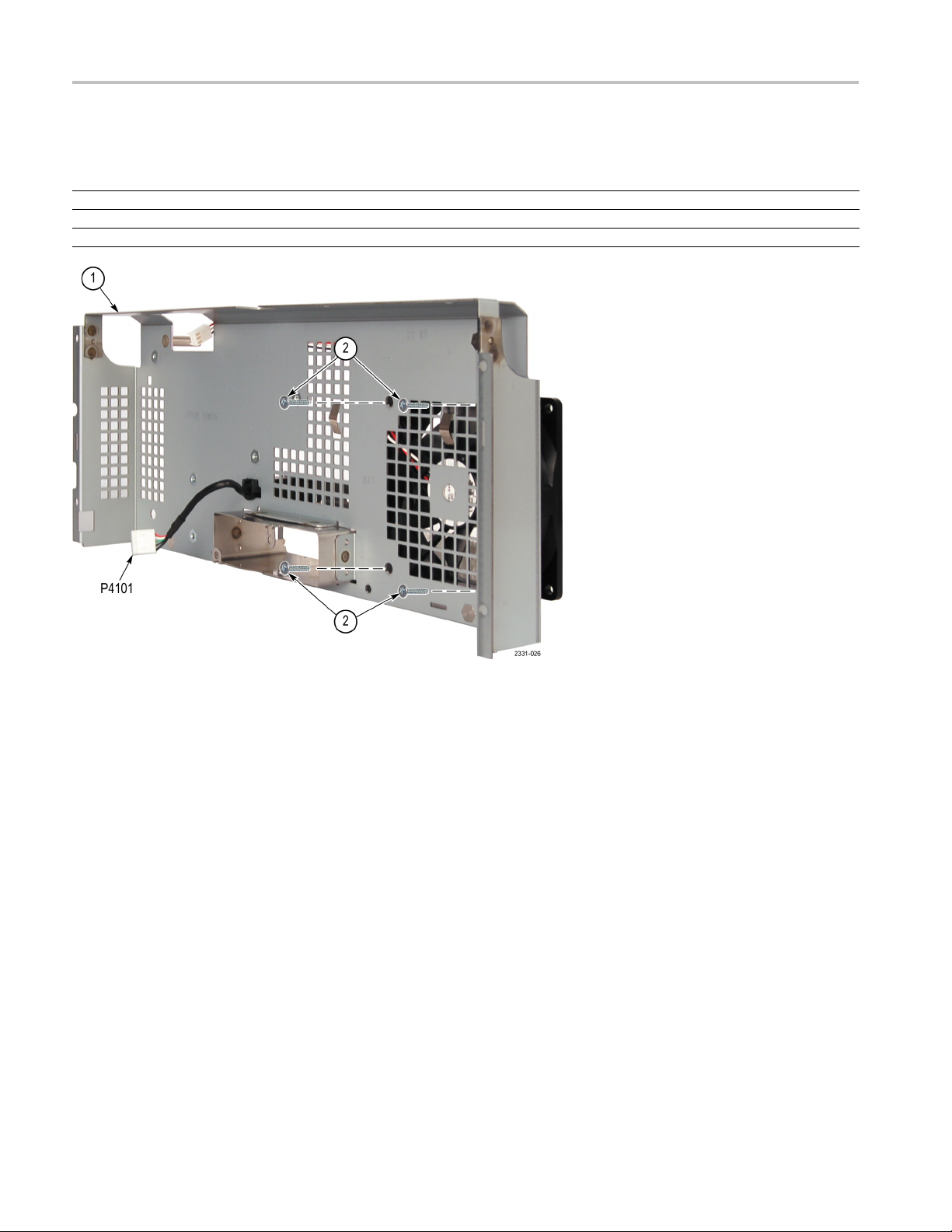
Rear Chassis
ow these steps to remove the rear chassis. You need to have previously
Foll
removed the Rear Case assembly. Use a TORX T15 screwdriver tip. (See
Figure 10.)
1. If not already disconnected, disconnect the power supply cable from J4701 on
the Main board, disconnect the backlight cable from P1 on the power supply.
2. Disconnect the fan cable from J4700 on the Main board.
3. Re
4.L
5. Remove the rear chassis and place it on the work surface with the fan up.
move the 14 T15 screws that attach the rear chassis to the front chassis.
When reinstalling, tighten these screws to 8 in/lb.
ift the rear chas sis slightly, and then disconnect the rear USB port cable
from J4101 on the Main board.
DPO2000 and MSO2000 Series Service Manual 19

Maintenance
Fan
Main Board
NOTE. Do not rem
the fan.
Follow these steps to
Rear Case assembly and the rear chassis. (See Figure 11.)
1. Lift the tape holdin
2. Turn the rear chassis over on the work surface so that the fan is on the bottom.
3. Remove the four T15 flat-head screws that attach the fan to the rear chassis.
4. Separate the fan and the rear chassis.
Follow these steps to remove the Main board. You need to have pre viously
removed the rear case assembly and the rear chassis. Use a TORX T15
screwdriver tip. (See Figure 12.)
1. Disconnect the display cable from J4300 on the Main board.
2. Disconnect the Front Panel cable from J4200 on the Main board.
3. Disconnect th
ove the fan from the rear chassis unless you are replacing
remove the fan. You need to have previously removed the
g the fan cable to the rear chassis, so that the cable is free.
e front USB port cable from J4100 on the Main board
Front End Assembly
4. Remove the 11 remaining T15 screws that connect the Main board to the
chassis. Whe
5. Lift the Main board up and set it on a static-free work surface.
6. When reinstalling, use care to align J400, on the back of the Main board,
with J1 on the Front End assembly. You ca n use the mounting holes as an
alignment
route the Front Panel cable above the Main board standoff.
Follow these steps to remove the Front End Assembly. You need to have
previou
Figure 13.)
1. Remove
2. Lift th
3. Place
sly removed the rear case, the rear cha ssis, and the Main board. (See
chassis. When reinstalling, tighten these screws to 8 in/lb.
e Front End assembly up from the front chassis. Be careful of the BNC
connectors until they clea r the front chassis.
the Front End assembly on a static-free work surface.
n reinstalling, tighten these screws to 8 in/lb.
aid. Apply slight pressure to seat the connector. Also, make sure to
the five T15 screws that attach the Front End assembly to the front
20 DPO2000 and MSO2000 Series Service Manual

Maintenance
Front Chassis
Display Module
Follow these st
removed the rear case assembly and the rear chassis. (See Figure 14.)
1. Remove the sev
panel assembly.
2. MSO2000 Ser
3. Lift the main chassis from the oscilloscope slightly, and then disconnect the
Front Panel
display module up.
4. When reins
and you want to avoid cutting new threads. One way to do this is to rotate the
screw counterclockwise until the threads drop into the grooves, then rotate the
screw clockwise until it is se ated. Tighten these screws to 8 in/lb.
Follow these steps to remove the display module. You need to have previously
removed rear case, rear chassis, and front chassis. Use a TORX T15 screwdriver
tip. (See Figure 15.)
1. Place the front chassis on the work surface with the display module up.
2. Remove the four T15 screws that secure the display module to the front
chassis.
eps to remove the Front Chassis. You must have previously
en T15 screws that connect the front chassis to the front
ies only – remove the digital probe guide.
cable from the front panel. Set the main chassis aside with the
talling, be careful with the screws. These are self-tapping screws,
Front Panel board
3. Gently lift the display up and off of the chassis, threading the backlight and
data cables through their respective holes in the chassis.
CAUTION. Be careful when removing and reinstalling the Display module cables.
If the connectors have bent pins or are installed incorrectly, the Display may
be destroyed.
Follow these steps to remove the Front Panel board. You need to have previously
removed the rear case, rear chassis, Main board, and front chassis. Use a TORX
T15 screwdriver tip. (See Figure 16.)
1. Remove all of the front-panel knobs, and then place the Front Panel assembly
face down on the work surface.
2. Disconnect the bezel button flex-cable from J13 on the Front Panel board.
DPO2000 and MSO2000 Series Service Manual 21

Maintenance
3. Remove the 12 T1
frame. Note that five of these screws have ground clips. Make sure to plac e
the ground clips on the correct screws when reinstalling. Note the ground clip
detail in Figure 5-11. When reinstalling, tighten these screws to 8 in/lb.
4. Lift the Front Panel board off of the chassis, and place it on a static-free
surface.
CAUTION. While the Front Panel board is out of the instrument, do not touch the
switchcontactsontheboardorontheflexible mat with your fingers. The oils on
your finger
s will degrade or damage the switch contacts.
5 screws that attach the Front Panel board to the front
5. When reinstalling, be careful with the screws. These are self-tapping screws;
id cutting new threads by slowly rotating the screw counterclockwise until
avo
the threads drop into the grooves, then rotate the screw clockwise until seated.
Application Key Guides
22 DPO2000 and MSO2000 Series Service Manual
Follow these steps to replace the Application Key guides. You need to have
eviously removed the rear case, rear chassis, Main board, front chassis, and
pr
Front Panel board. Use a Phillips screwdriver tip. (See Figure 17.)
NOTE. Do not remove the Application Key guides from the Front Panel board
unless you are replacing them due to damage.

Maintenance
1. Remove the two fl
Panel assembly. These screws go completely through the guides on both
sides of the circuit board.
2. Turn the Front Panel assembly over and remove the two flat-head Phillips
screws from the front side of the Front Panel assembly.
3. When reinstalling these screws, tighten them to only 2 in/lb.
CAUTION. Do not overtighten the screws in the Application Key guides.
Overtightening these screws will destroy the guide.
at-head Phillips screws from the back side of the Front
DPO2000 and MSO2000 Series Service Manual 23

Maintenance
Troubleshooting
This section contains information and procedures to help you isolate a defective
module in the D PO2000 series or the MSO2000 series oscilloscopes.
WARNING. Before doing this or any other procedure in this manual, read the
General Safety Summary and Service Safety Summary found at the beginning of
this manual
electrical components, read Preventing ESD.
. Also, to prevent possible injury to service personnel or damage to
Adjustment After Repair
Required Tools and
Equipment
If you replace the Main board or the Front End assembly, you must adjust the
instrument after repair. Refer to the Adjustment Procedures.
You need
Tools and equipment Example
DMM
the following equipment to troubleshoot the instrument.
3.5 digit or better DMM; F luke 80 Series or
equivalent
24 DPO2000 and MSO2000 Series Service Manual

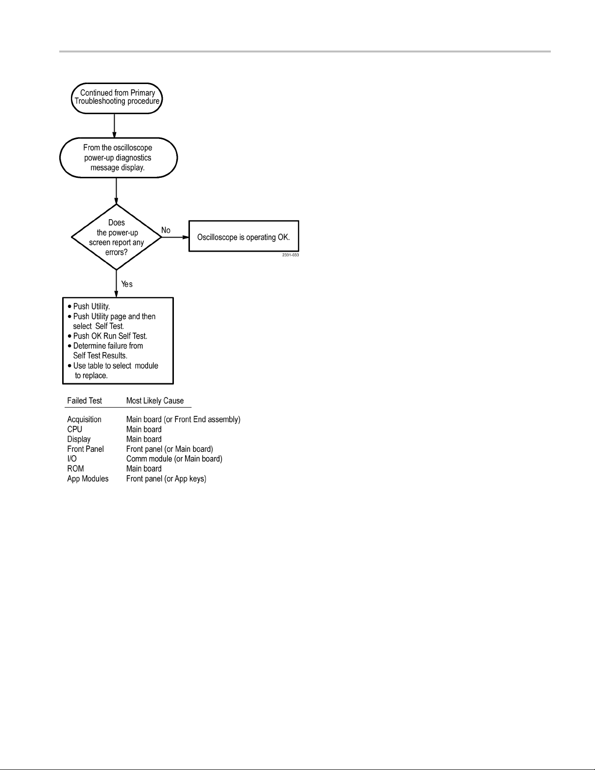
Troubleshooting Procedure
The following figures are troubleshooting procedure flowcharts. Use them to
troubleshoot an instrument failure.
WAR NI NG . Before removing the rear case, disconnect the power cord from the
line voltage source. Failure to do so could cause serious injury or death.
Maintenance
Figure 3: Primary troubleshooting procedure
DPO2000 and MSO2000 Series Service Manual 25

Maintenance
Figure 4: AC power supply troubleshooting procedure
26 DPO2000 and MSO2000 Series Service Manual
Maintenance
Figure 5: Module isolation troubleshooting procedure
Unpacking and Repacking Instructions
This section contains the information needed to unpack the oscilloscope and
ack it for shipment or storage.
rep
Unpacking
DPO2000 and MSO2000 Series Service Manual 27
The oscilloscope and its standard accessories are carefully packed at the factory in
a shipping carton. If, upon receipt, damage to the shipping carton is evident, notify
e shipper. Tektronix, Inc. is not responsible for damage caused during shipping.
th

Maintenance
Repacking
If you have not a
accessories from the shipping carton and inspect them for damage. Save the
shipping carton for repacking or storage.
Useacorruga
pounds (125 kg) and with an inside dimension at least six inches (15.25 cm)
greater than the instrument dimensions.
If the instrument is being shipped to a Tektronix Service Center, enclose the
following information:
The owner's address
Name and p
Type and serial number of the instrument
Reason for returning
A complete description of the service required
Seal the shipping carton with an industrial stapler or strapping tape.
Mark the address of the Tektronix Service Center and also your own return address
on the shipping carton in two prominent locations. See www.tektronix.com/service
to find a service center near you.
lready done so, carefully remove the oscilloscope and its
ted cardboard shipping carton having a test strength of at least 275
hone number of a contact person
Storage
The oscilloscope should be stored in a clean, dry environment. The following
environmental characteristics apply for both shipping and storage:
Temperature range: -20 °C to +60 °C
titude: To 15,000 m
Al
See the DPO2000 and MSO2000 Series Specifications and Performance
rification Technical Reference for a complete listing of the environmental
Ve
characteristics.
28 DPO2000 and MSO2000 Series Service Manual
Replaceable Parts List
This chapter contains a list of the replaceable modules for the DPO2000 and
MSO2000 Series Oscilloscopes. Use this list to identify and order replacement
parts.
Parts Order
ing Information
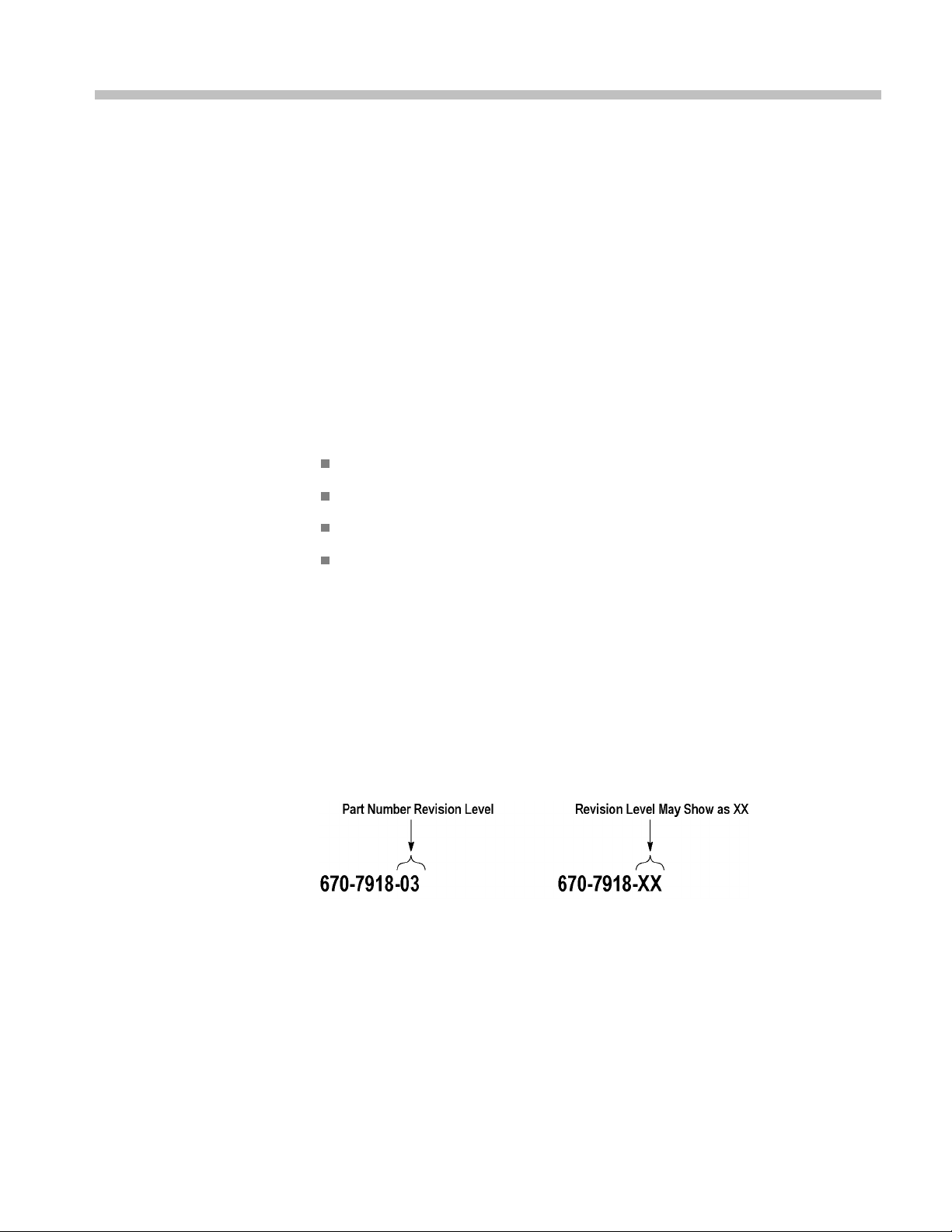
Part Number Revision
Level
Replacement parts are available through your local Tektronix field office or
representative.
Changes to Tektronix products are sometimes made to accommodate improved
components as they become available and to give you the benefit of the latest
improvem
following information in y our order.
If you order a part that has been replaced with a different or improved part, your
local Tektronix field office or representative will contact you concerning any
change in part number.
Change information, if any, is located at the rear of this manual.
Tektronix part numbers contain two digits that show the revision level of the
part. For some parts in this manual, you will find the letters XX in place of the
revision level number.
ents. Therefore, when ordering p arts, it is important to include the
Part num
Instrument type or model number
Instrument serial number
Instrument modification number, if applicable
ber(Seepage29.)
When you order parts, Tektronix will provide you with the most current part for
your product type, serial number, and modification (if applicable). At the time of
your order, Tektronix will determine the part number revision level needed for
your product, based on the information you provide.
Module Servicing
DPO2000 and MSO2000 Series Service Manual 29
Modules can be serviced by selecting one of the next three options. Contact your
local Tektronix service center or representative for repair assistance.

Replaceable Parts List
Module Exchang
remanufactured module. These modules cost significantly less than new modules
and meet the same factory specifications. For more information about the module
exchange program, call 1-800-833-9200, extension 2.
Module Repair and Return. You may ship your module to us for repair, after
which we wil
lreturnittoyou.
New Modules. You may purchase replacement modules in the same way as other
replacement parts.
Using the Replaceable Parts List
This section contains a list of the mechanical and/or electrical components that
are replaceable for the instrument. Use this list to identify and order replacement
parts. The following table describes each column in the parts list.
Column Column name Description
1
2 Tektronix Part Number
3 and 4
5
6
Figure & Index Number Items in this section are referenced by figure and index numbers to the exploded
view illustrations that precede the list.
Use this part number when ordering replacement parts from Tektronix.
Serial Number Column three indicates the serial number at which the part was first effective. Column
four indicates the serial number at which the part was discontinued. No entries
indicates the part is good for all serial numbers.
Qty This indicates the quantity of parts used.
Name & Description An item name is separated from the description by a colon (:). Because of space
limitations, an item name may sometimes appear as incomplete. Use the U.S. Federal
Catalog handbook H6-1 for further item name identification.
e. In some cases you may exchange your module for a
Abbreviations
Exploded Views
Abbreviations conform to American National Standard ANSI Y1.1-1972.
The following diagrams show the module-level exploded views of the DPO2000
and MSO2000 Series oscilloscopes. Each exploded view is indexed by the
numbers in the figure.
30 DPO2000 and MSO2000 Series Service Manual

Replaceable Parts List
Table 3: Front t
rim
Fig. &
index
number
Tektronix par
number
t
Serial no.
effective
Serial no.
discont'd Qty Name & description
5-1 Front trim
1
-1 366-0863-00
-2 366-0862-00 6
-3 366-0877-00 1
-4 358-0890-00 1
-5
-6
-7
1
Number will vary depending on oscilloscope model.
366-0876-00 1
800-0038-00 1
800-0039-00 1
800-0040-00 1
200-5039-00 1
7
1
ASSEMBLY, KNOB; .685 DIAMETER
ASSEMBLY, KNOB; .470 DIAMETER
KNOB; LARGE, WSP, JOG, SHUTTLE, FSN.ASM
BUSHING, SPACER, RING JOG-SHUTTLE
KNOB; SMALL, WSP, JOG - SHUTTLE, FSN.ASM
FINAL ASSEMBLY; MECHANICAL; DPO2EMBD
FINAL ASSEMBLY; MECHANICAL; DPO2AUTO
FINAL ASSEMBLY; MECHANICAL; DPO2COMP
COVER, DOOR OPTION KEYS
Figure 6: Front trim
DPO2000 and MSO2000 Series Service Manual 31
Replaceable Parts List
Table 4: Rear tr
im
Fig. &
index
number
Tektronix par
number
t
Serial no.
effective
Serial no.
discont'd Qty Name & description
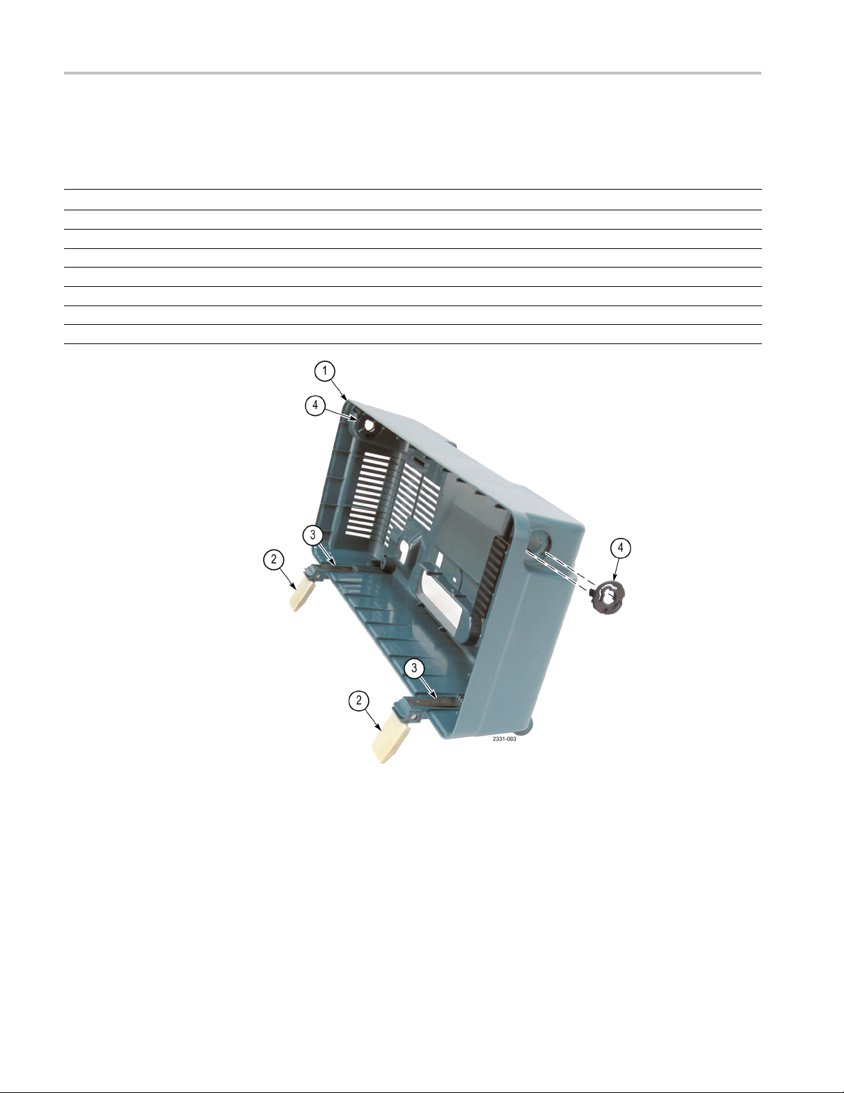
5-2 Rear trim
-1 650-5016-00 1
-2 348-1910-00 2
-3 214-5148-00 2
-4 105-1170-00 2
367-0547-00 1
REAR CASE SUB ASSEMBLY; MSO/DPO2000
**ATTACHED PARTS**
FOOT, FRONT CABINET, HINGED
SPRING FRONT FOOT
ACTUATOR, CAM FOLLOWER HANDLE SLIPRING
HANDLE, CARRYING BASE
**END ATTACHED PARTS**
Figure 7: Rear trim
32 DPO2000 and MSO2000 Series Service Manual
Replaceable Parts List
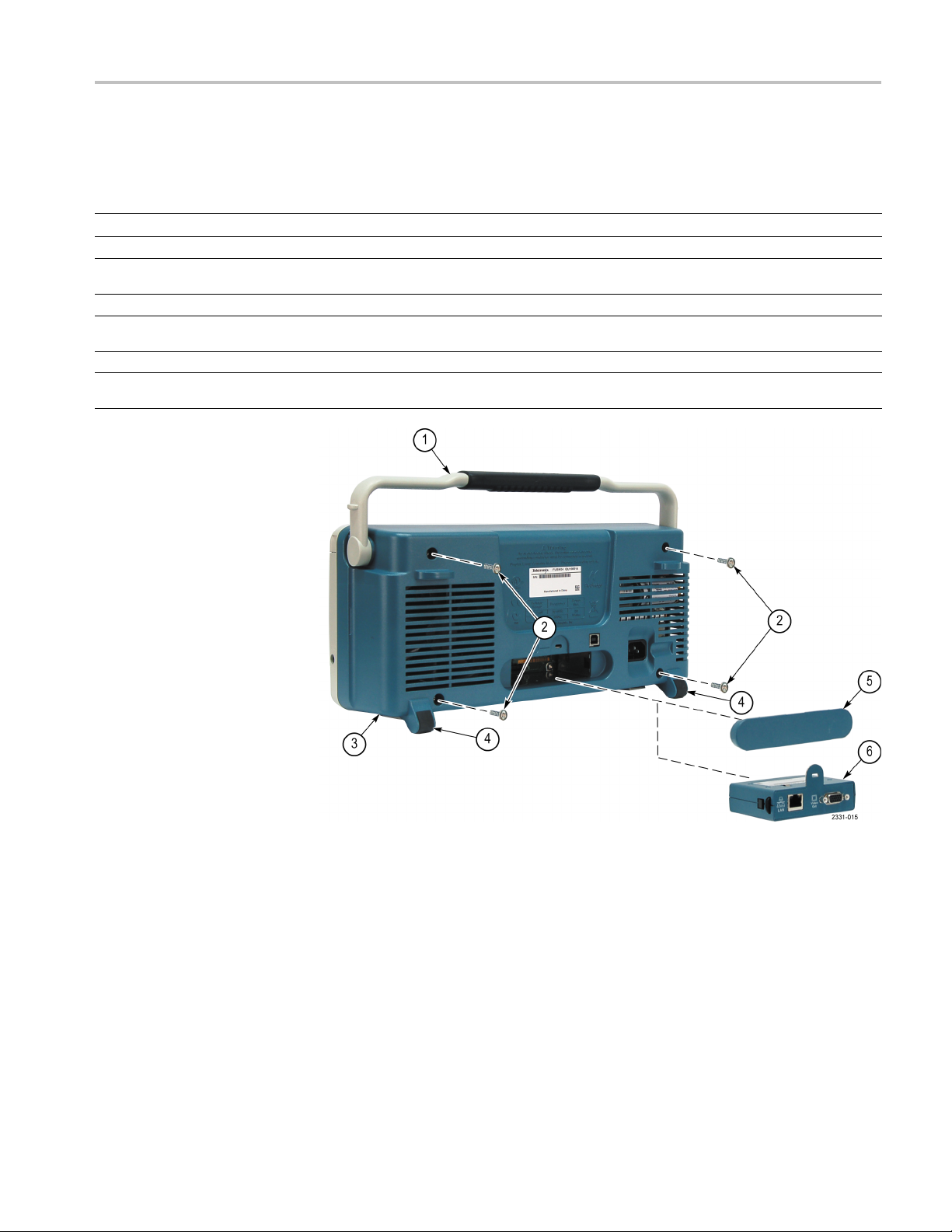
Table 5: Rear ca
se
Fig. &
index
number
Tektronix par
number
t
Serial no.
effective
Serial no.
discont'd Qty Name & description
5-3 Rear case
-1 367-0547-00 1
-2 211-1272-00 4
-3 650-5016-00 1
-4 348-1909-00 2
-5
-6
200-5046-00 1
—————
1
HANDLE, (PART OF 650-5016-00_
SCREW, MACHINE; 6-32 X 0.250, PNH, STEEL, ZINC FINISH, T-15
TORX DR
REAR CASE SUB ASSEMBLY; MSO/DPO2000
FOOT REAR; SAFETY CONTROLLED, PART OF 650-5016-00
REAR CASE SUB ASSEMBLY
COVER, BLANK OPTION MODULE
ETHERNET AND EXTERNAL MONITOR OUT CONNECTIVITY
MODULE FOR DPO/MSO2000 SERIES: DPO2CONN
Figure 8: Rear case
DPO2000 and MSO2000 Series Service Manual 33

Replaceable Parts List
Table 6: Power s
Fig. & index
number
upply
Tektronix p art
number
Serial no.
effective
Serial no.
discont'd
Qty
Name & description
5-4 Power supply
-1 119-7038-00 1
-2 119-7266-00 1
-3 211-1272-00 3
-4 211-1275-00 2
FAN,TUBEAXIAL; 12VDC,0.21A,2.52W, 1.45M^3/MIN,
3150RPM,33DB
POWER SUPPLY
9A,+3.3V4.5A,-5V0.5A,+13V0.3AOUT,CCFLBACKLIGHT
INVERTER, LINE TRIGGER SIGNAL, SAFETY CONTROLLED
SCREW,MACHINE; 6-32 X 0.250,PNH,STL,ZNPL,T-15 TORX DR
SCREW, MACHINE; W/HEAVY PATCH THREADLOCKING MATERIAL;
6-32 X 0.312
L, PNH,STL,ZNPL, T15
A,92MM X 92MM X 25MM; SAFETY CONTROLLED
: CUSTOM AC-DC, 85-264 VAC 45-440HZ IN, +5 V
Figure 9: Power supply
34 DPO2000 and MSO2000 Series Service Manual

Replaceable Parts List
Table 7: R ear ch
Fig. & index
number
assis
Tektronix part
number
Serial no.
effective
Serial no.
discont'd
5-5
-1 441-2503-00 1
-2 211-1272-00 14
Qty
Name & description
Rear chassis
CHASSIS, ASSEMBLY REAR
SCREW, MACHINE; 6-32 X 0.250, PNH, STEEL, ZINC FINISH, T-15
TORX DR
Figure 10: Rear chassis
DPO2000 and MSO2000 Series Service Manual 35
Replaceable Parts List
Table 8: Fan
Fig. & index
number
5-6 Fan
-1 1
-2 213-1150-00 4
Tektronix p art
number
Serial no.
effective
Serial no.
discont'd
Qty
Name & description
CHASSIS, ASSEMBLY REAR. (See Table 7.)
SCREW, FLAT HEAD, T15 FAN SCREW, M5X10
Figure 11: Fan
36 DPO2000 and MSO2000 Series Service Manual

Replaceable Parts List
Table 9: M ain bo
Fig. & index
number
ard
Tektronix part
number
Serial no.
effective
Serial no.
discont'd
5-7
-1
-2 211-1272-00 11
870-0318-00 1
870-6186-00 1
870-0024-00 1
870-0319-00 1
870-0026-00 1
870-0025-
00
Qty
1
Name & description
Main board
CIRCUIT BD ASSY; MAIN; TESTED;389386100;
MSO2024 ONLY
CIRCUIT BD AS
MSO2014 ONLY
CIRCUIT BD ASSY; MAIN 2 CHN TESTED;389386100;
MSO2012 ONLY
CIRCUIT BD ASSY; MAIN; CH TESTED; 389386100;
DPO2024 ONL
CIRCUIT BD A
DPO2014 ONLY
CIRCUIT BD ASSY; MAIN 2 CHN TESTED; 389386100;
DPO2012 ONLY
SCREW,MACHINE; 6-32 X 0.250,PNH,STL,ZNPL,T-15 TORX DR
SY; MAIN 4 CHN TESTED; 389386100;
Y
SSY; MAIN 4 CHN TESTED; 389386100;
re 12: Main board
Figu
DPO2000 and MSO2000 Series Service Manual 37

Replaceable Parts List
Table 10: Front
Fig. & index
number
end board
Tektronix p art
number
Serial no.
effective
Serial no.
discont'd
Qty
Name & description
5-8 Front end board
-1 441-2502-00 1
-2
-3 211-1272-0
-4 351-1124-0
870-6261-00 1
870-0020-00 1
0
0
5
1
CHASSIS, ASSEMBLY MAIN
CIRCUIT BD ASSY;FRONT END 4 CH BRD; 389391100; TESTED;
DPO2014, DPO
CIRCUIT BD AS
DPO2012, MSO2012
SCREW,MACHINE; 6-32 X 0.250,PNH,STL,ZNPL,T-15 TORX DR
GUIDE, MSO PROBE
MSO MODELS ONLY
2024, MSO2014, and MSO2024
SY;FRONT END 2 CH BRD
Figure 13: Front end assembly
38 DPO2000 and MSO2000 Series Service Manual

Replaceable Parts List
Table 11: Main c
Fig. & index
number
hassis
Tektronix part
number
Serial no.
effective
Serial no.
discont'd
Qty
Name & description
5-9 Main chassis
-1
-2 211-1273-00
7
CHASSIS, ASSEMBLY MAIN. (See Table 10.)
SCREW, PT; K35-1.57, PAN HEAD, STL, ZNPL, T-15
Figure 1
4: Main chassis
DPO2000 and MSO2000 Series Service Manual 39

Replaceable Parts List
Table 12: Displ
Fig. & index
number
ay
Tektronix p art
number
Serial no.
effective
Serial no.
discont'd
Qty
Name & description
5-10 Display
-1
-2 850-0057-00 1
-3 211-1272-00 4
CHASSIS, ASSEMBLY MAIN. (See Table 10.)
FINAL ASSEMBLY;LCD DISPLAY COLOR
SCREW,MACHINE; 6-32 X 0.250,PNH,STL,ZNPL,T-15 TORX DR
Figure 15: Display
40 DPO2000 and MSO2000 Series Service Manual

Replaceable Parts List
Table 13: Front
Fig. & index
number
panel board
Tektronix part
number
Serial no.
effective
Serial no.
discont'd
Qty
Name & description
5-11 Front panel board
-1
-2
-3 211-1273-00 13
-4 131-8139-00
-5
879-0102-01 1
878-0027-01 1
650-5027-00 1
650-5026-00 1
650-5018-00 1
650-5017-
174-5373-00 1
00
CIRCUIT BD SUBASSY; FRONT PANEL BD 2CH;389390300
MSO2012, DPO2
CIRCUIT BD SU
MSO2014, MSO2024, DPO2014, DPO2024
FRONT CASE SUB ASSEMBLY; 4 CH
MSO2014 & MSO2024
FRONT CASE SUB ASSEMBLY; 2 CH
MSO2012
FRONT CASE S
1
5
DPO2014 & DPO2024
FRONT CASE SUB ASSEMBLY; 2CH
DPO2012
SCREW, PT; K35-1.57, PAN HEAD, STL, ZNPL, T-15
CONTACT, SPRING; FRONT PANEL ELEC
CABLE ASSEMBLY, FRONT PANEL
012
BASSY;FRONT PANEL 4 CH; 389390300
UB ASSEMBLY; 4 CH
Figure 16: Front panel board
DPO2000 and MSO2000 Series Service Manual 41

Replaceable Parts List
Table 14: Optio
Fig. & index
number
n key guides
Tektronix p art
number
Serial no.
effective
Serial no.
discont'd
5-12
-1
-2 351-1109-00 2
-3 213-1149-00 4
————
Qty
1
Name & description
Option key gui
CIRCUIT BD SUBASSY; FRONT PANEL BD. (See Table 13.)
GUIDE,KEY; OPTIONAL SW
SCREW,TPG,TF; 2-28 X.5,PLASTITE, FLAT
HEAD,PHILLI
des
PS,STL,ZNPL
re 17: Option key guides
Figu
42 DPO2000 and MSO2000 Series Service Manual

Replaceable Parts List
Table 15: Repla
Fig. & index
number
No Image
Tektronix part
number
See Description
See Description
See Description
-4118-xx
063
-0784-01
010
-6316-00
010
-3508-00
196
ceable parts list: DPO2000 and MSO2000 Accessories
Serial no.
effective
Serial no.
discont'd
Qty
Name & description
STANDARD ACCESSORIES
1
CABLE ASSY, POWER; ONE OF:
Option Country P/N
A0
A1
A2
A3
A5
A6
A10
A11
1
MANUAL, TECH, USER, DPO/MSO2000 Series
Option
L0
L1
L2
L3
L4
L5
L6
L7
L8
L9
L10
1
LABEL, FRONT PANEL, LANGUAGE OVERLAY, DPO/MSO2000 Series
Option
L1
L2
L3
L4
L5
L6
L7
L8
L9
L10
1
DPO/MSO2000 SERIES DOCUMENTATION CD
1
PROBE ASSEMBLY; SERVICE REPLACEMENT;P2221; EXPORT
1
16 CHANNEL DIGITAL PROBE, GENERAL PURPOSE
2
LEADSET, GENERAL PURPOSE; 8 CHANNEL DIGITAL PROBE (FLYING LEADS)
North America
Universal Euro
United Kingd
Australia
Switzerland
Japan
China
India
Language
English
French
Italian
German
Spanish
e
Japanes
Portugese
Sim. Chinese
inese
Trad. Ch
Korean
Russian
ge
Langua
French
Italian
n
Germa
Spanish
Japanese
ugese
Port
Sim. Chinese
Trad. Chinese
an
Kore
Russian
om
161-0348-00
161-0343-00
161-0344-00
161-0346-00
161-0347-00
161-0342-0
161-0341-00
161-0349-00
P/N
071-2319-00
071-2320-00
-00
071-2321
071-2322-00
071-2323-00
4-00
071-232
071-2325-00
071-2326-00
7-00
071-232
071-2328-00
071-2329-00
P/N
335-2020-00
335-2021-00
022-00
335-2
335-2023-00
335-2024-00
2025-00
335335-2026-00
335-2027-00
2028-00
335335-2029-00
0
OPTIONAL ACCESSORIES
1-2331-00
07
9-7465-00
11
020-2924-01 1
067-1686-00 1
016-2010-00
200-5045-00
1
MANUAL, TECH: SERVICE, ENGLISH; DPO/MSO2000 SERIES
1
POWER SUPPLY; EXTERNAL, DESKTOP (W/SPECIAL 2.1MM ID BARREL CONNECTOR;
50W, 12VDC 4.2A OUT, 90 - 264VAC 47 - 440 HZ IN; 78% EFF, UL, CSA, PSE, CCC ,SAFETY
ONTROLLED
C
EMO KIT: ED DEMO BOARD 2, TECH MANUAL TRAINING AID
D
OWER DESKEW/CALIBRATION FIXTURE;DPO7XXX
P
1
OFTCASE, ACD2000
S
**INCLUDED PARTS**
COVER, FRONT PROTECTIVE
1
**END INCLUDED PARTS**
DPO2000 and MSO2000 Series Service Manual 43
 Loading...