

Page 1
DOMI
Digital Output Module
The DOMl Digital Output Module offers 16 channels of optically isolated digital output.
These channels are factory configured as TTL compatible voltage outputs. By removing
resistors and jumpers, output may be configured as switches. Functioning as switches,
the output channels can control loads up to +28V.
Digital output channels are grouped into two ports of eight channels; each port treated
as a single byte from software. This grouping allows simultaneous updating of up to
eight channels, and enables communication with 4 and &bit TTL devices.
Digital Output Modules can be installed in any slot of the Series 500. To install the
module, remove the top cover and install the board with the components facing the
power supply.
CAUTION: Always turn off the mainframe power before installing or removing
modules. To minimize the possibility of EM1 radiation, never operate the system with
the top cover removed.
User-Configured Components
The DOMl is factory configured to provide isolated TTLcompatible outputs. In this
configuration, external +5V and ground wires must be connected to respective module
terminals. By moving the positions of two jumpers (Wll.7 and Wllg), The module can
also be used in a non-isolated TTLcompatible configuration that uses the module’s own
+5V and ground connections.
Resistors to ground and wire jumpers to +5V may be removed to configure individual
outputs as switches, thus allowing circuits with potentials as high as 28V to be
controlled.
Connections to the module are made to screw terminals located along the top edge of
the module. Each terminal accepts 16-24 gauge wire leads. Used-configurable components are summarized in Table 1.
Document Number: 500-935-01 Rev. B
DOMl-1
Page 2
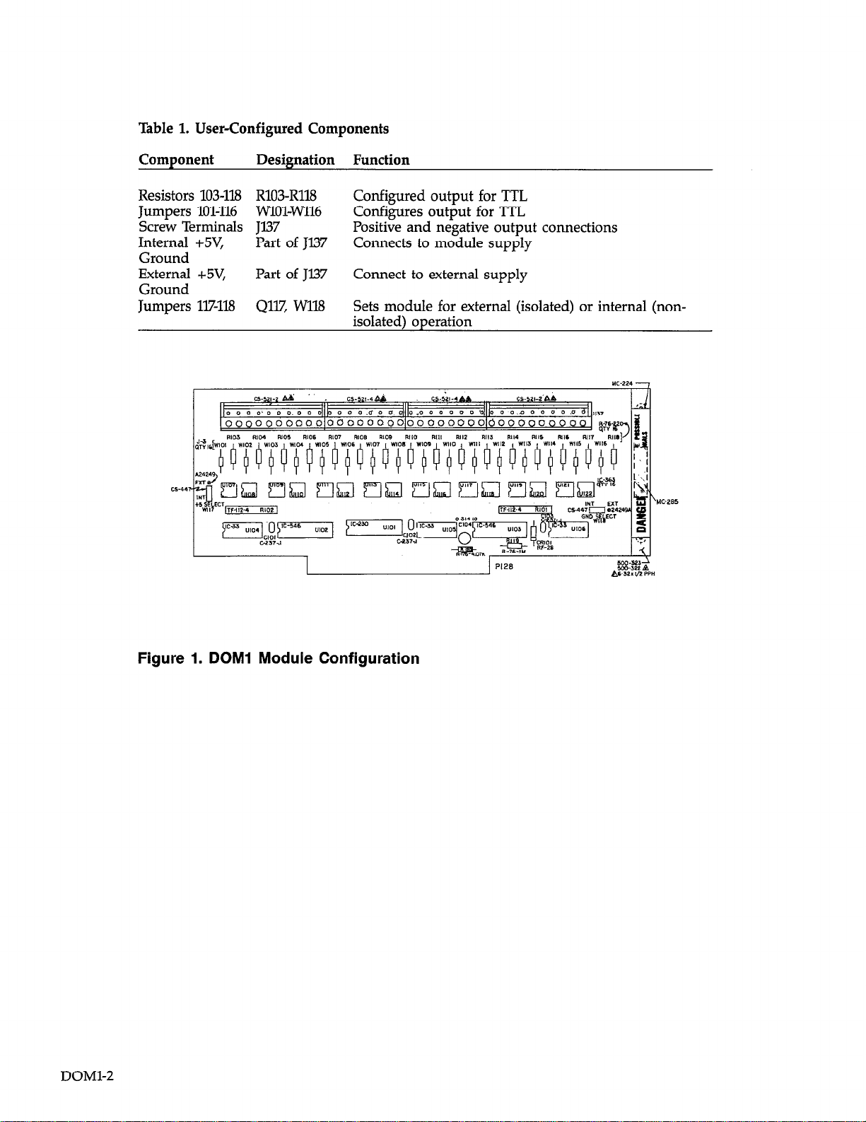
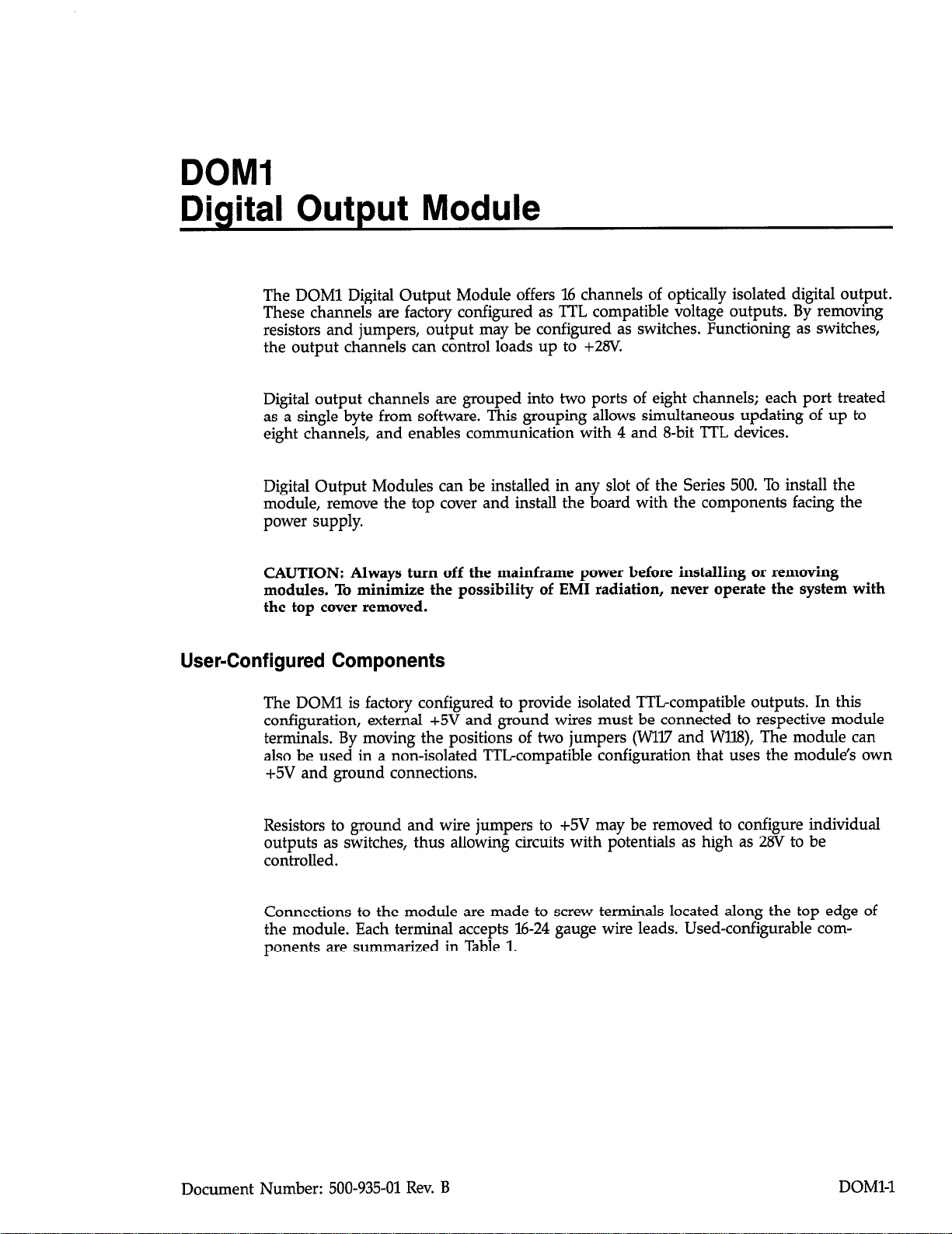
Table 1. User-Configured Components
Component
Resistors 103-118 R103-R118 Configured output for TTL
Jumpers 101-116 WlOIWll6 Configures output for TTL
Screw Terminals Jl37
Internal +5V, Part of Jl37 Connects to module supply
Ground
External +5V,
Ground
Jumpers 117-118 4117, Wll8 Sets module for external (isolated) or internal (non-
Designation Function
Positive and negative output connections
Part of Jl37
Connect to external supply
isolated) operation
Figure 1. DOMl Module Configuration
DOMl-2
Page 3
Connections
A terminal strip containing all module connecting points is located at the top of the
board. In addition to (+) and (-) connections for each of the 16 channels, there are also
terminals for both internal and external +5V ground connections. These terminals are
marked on the board. A typical connecting scheme is illustrated in Figure 2.
CAUTION: Use shielded cable to minimize EM1 radiation. Connect one end of the
shield to internal or external ground depending on module configuration as described
below.
WARNING: User-supplied lethal voltages may be present on the terminals.
‘ERNAL SUPPLY
Figure 2. Connections for Isolated TTL Outputs
As shipped, the DOMl module is configured for isolated TTL outputs. With this configuration, external +5V and ground must be connected to the appropriate terminals.
See Figure 2 for typical connections. Note that signal high is connected to the (-) chan-
nel of the output, while signal low is connected to external ground.
By moving Wl17 and Wll.8 to the internal positions, the module can be converted for
use with the Series 500 system supply. With this configuration, signal high would be
connected to the (-) terminal of the channel in question, while signal low would be
connected to module ground.
Note that the module draws 6OOmA when configured to operate in the internal mode.
This factor may be reduced to about 350mA when operating from an external supply.
Conversion to Switching Outputs
Each channel on the DOMl module may be individually converted into a switching
output that will control up to 28V. To convert a channel, remove the 2203 resistor and
DOMl-3
Page 4

jumper wire associated with that channel. The load and power source should then be
connected as shown in Figure 3. Be sure to observe proper polarity (plus to +, minus
to -). When a “1” is written to the channel through software, the output switch will
close, and power will be applied to the load. When a “0” is written to the channel, the
switch will be turned off, and power will be removed.
NOTE: RESISTOR AND JUMPER
MUST BE REMOVED
Figure 3. Connections for Switching Output
Commands
DOMl module commands are listed in Table 2. Table 3 summarizes the locations for
slot-dependent commands.
Table 2. Commands Used with the DOMl Module
Command Location
DIGITAL A
DIGITAL B
r NOTE: +V=28V MAX
Slot-dependent CMDA
Slot-dependent CMDB
DOMl-4
Page 5

Table 3. Locations for Slot-Dependent Commands
sI.ot CMDA CMDB
Slot 1
Slot 2
Slot 3
Slot 4
Slot 5
Slot 6
Slot 7
Slot 8
Slot 9
Slot l.0
DIGITAL A
Location: Slot-dependent CMDA
The command location DIGITAL A is used to set the status of channels O-7 (Port A) on
the DOMl module. This location should always be written to, and not read. Note that
this command affects all eight channels of Port A simultaneously.
The value written to the DIGITAL A location should be the equivalent of an 8-bit
binary number, with the status of the 8 bits (1 or 0) representing the status of the 8
channels (on or off). Table 4 describes the bit configuration of values written to
DIGITAL A.
CFF80
CFF82
CFF84
CFF86
CFFSS
CFF8A
CFF8C
CFWE
CFF90
CFF92
CFF81
CFF83
CFF85
CFF87
CEF89
CFF8B
CFF8D
CEF8F
cEE91
CFF93
Table 4. Bit Configuration for DIGITAL A
w
Cl-17 Ch6
128 64 32 16 8
CWChO = Channels 7 through 0
128, 64, etc. = Decimal bit values
To change the status of one output channel while leaving the rest unchanged, the
status of all the channels must be known. Because this location cannot be read, a
variable in the controlling program should be assigned to the current status of Port A
and updated each time the status of a channel is changed. When the current status of
all bits (channels) is known, the value of the variable can be changed in status for one
or more channels, and this new number written to the DIGITAL A location.
In assembly language, this modification can be made using the logical AND and logical
OR statements. When turning a single channel on, the variable value representing the
current port status should be ORed with a number equivalent to an 8 bit binary value,
with O’s in the bit positions affecting channels to remain the same, and a 1 in the posi-
tion affecting the channel to be turned on.
D6 D5 D4 D3 D2 Dl DO
Ch5 Ch4 Ch3
Ch2 Chl ChO
4 2 1
DOMl-5
Page 6

When turning a single channel off, the variable value should be ANDed with a number
equivalent to an B-bit binary value, with l’s in the bit positions of all channels to be unchanged, and a 0 in the position of the channel being turned off.
From BASIC, the decimal value of the bit to be turned on or off should be added to
(off to on), or subtracted from (on to of decimal number that represents the current
port status. For example, to turn channel 2 off, it would be necessary to subtract 4 from
the decimal value representing the port status. To turn channel 6 on, it would be
necessary to add 64.
DIGITAL B
Location: Slot-dependent CMDB
DIGITAL B is the equivalent of DIGITAL A, operating in exactly the same manner, but
addressing Port B of the DOMl (Channels S-15). See Table 5.
Table 5. Bit Configuration for DIGITAL B
l37
Chl5
128
Chl5-Ch8 = Channels 25 through 8
128, 64, etc. = Decimal bit values
D6 D5 D4 D3 D2 Dl DO
Ch14 Ch13 Ch12
64 32 16
Theory of Operation
Refer to schematic number 500-246 for the following discussion.
Data from the system data bus arriving at the DOMl module is first buffered by octal
buffer IX01 (74LS244), and latched into U102 and U103, two transparent octal D-type latches (74LS373). The latches are refreshed by the negative transition of commands lines
CMDA and CMDB, respectively. The output of latches U102 and U103, buffered by
U104, U105 and U106 (7407 hex inverters used as current drivers), drives the LED
transmitters in optical isolators U107Ul22. An independent isolator is provided for each
output channel. The receiver of the isolator is a high-gain Darlington transistor pair,
which is connected across the positive and negative output terminals of the channel.
The inputs of the isolator are pulled up to +5V through resistors RlOl and R102.
Chll
8 4 2
ChlO Ch9
Ch8
1
DOMl-6
Resistor locations R103-Rll8 are factory installed 22OQ resistors between the emitter terminal of each output channel and ground. Jumpers WlOl-Wll6 connect the isolator collector terminals to +5V. With these resistors and jumpers installed, the outputs are configured to be TTL compatible. Meanwhile, jumpers Wl17 and Wl18 allow the selection
of internal or external +5V and ground connections.
Page 7

DOMl Specifications
Output channels: 16
Output characteristics:
TTLcompatible
Logic 0 output: 0.4V max at 1.6mA sink
Logic 1 output: 3.75V min at lmA source
Transition time: 1OOpsec
User configurable characteristics:
Output voltage: 28V max (user supplied source)
Output current: 50mA max (user supplied source)
Isolation:
Technique: optical
Channel-to-channel or channel-to-ground: 500V peak
DOMl-7
Page 8

MC-924 -
DOMl-8
DOMl COMPONENT LAYOUT
Page 9

-
-
-
Y
-
i
I III!
 Loading...