


DMM912, DMM914 & DMM916 Digital Multimeter Instructions
070-9791-01
1

Copyright Tektronix, Inc. All rights reserved.
Tektronix products are covered by U.S. and foreign patents,
issued and pending. Information in this publication supercedes
that in all previously published material. Specifications and
price change privileges reserved.
Printed in Hong Kong.
Tektronix, Inc., P.O. Box 1000, Wilsonville, OR 97070–1000
TEKTRONIX, TEK, and TekTools are registered trademarks of
Tektronix, Inc.

WARRANTY SUMMARY
Tektronix warrants that the products it manufactures and
sells will be free from defects in materials and workmanship for a period of three years from the date of purchase
from an authorized Tektronix distributor. If a product or
CRT proves defective within the respective period,
Tektronix will provide repair or replacement as described
in the complete warranty statement.
To arrange for service or obtain a copy of the complete
warranty statement, please contact your nearest T ektronix
distributor .
EXCEPT AS PROVIDED IN THIS SUMMARY OR
THE APPLICABLE WARRANTY STATEMENT,
TEKTRONIX MAKES NO WARRANTY OF ANY
KIND, EXPRESS OR IMPLIED, INCLUDING WITHOUT LIMITATION THE IMPLIED WARRANTIES OR
MERCHANTABILITY AND FITNESS FOR A PARTICULAR PURPOSE. IN NO EVENT SHALL
TEKTRONIX BE LIABLE FOR INDIRECT, SPECIAL
OR CONSEQUENTIAL DAMAGES.


Table of Contents
Safety 1–3. . . . . . . . . . . . . . . . . . . . . . . . . . . . . . . . . .
Product Description 1–5. . . . . . . . . . . . . . . . . . . . . . .
Front Panel Overview 1–7. . . . . . . . . . . . . . . . . . . . . .
Display indicators 1–8. . . . . . . . . . . . . . . . . . . . . . .
Buttons 1–10. . . . . . . . . . . . . . . . . . . . . . . . . . . . . .
Shifted buttons 1–12. . . . . . . . . . . . . . . . . . . . . . . . .
Setup buttons 1–14. . . . . . . . . . . . . . . . . . . . . . . . . .
Rotary dial functions 1–16. . . . . . . . . . . . . . . . . . . . .
Input connectors 1–18. . . . . . . . . . . . . . . . . . . . . . . .
Operating Basics 1–20. . . . . . . . . . . . . . . . . . . . . . . . . .
Safe test lead connections 1–21. . . . . . . . . . . . . . . . .
AC voltage measurements 1–22. . . . . . . . . . . . . . . . .
DC voltage measurements 1–23. . . . . . . . . . . . . . . .
AC + DC measurements 1–24. . . . . . . . . . . . . . . . . .
Frequency measurements 1–25. . . . . . . . . . . . . . . . .
Resistance measurements 1–26. . . . . . . . . . . . . . . .
Continuity checks 1–27. . . . . . . . . . . . . . . . . . . . . . .
Diode testing 1–28. . . . . . . . . . . . . . . . . . . . . . . . . .
Capacitance measurements 1–29. . . . . . . . . . . . . . .
Current measurements 1–30. . . . . . . . . . . . . . . . . . .
Temperature measurements 1–31. . . . . . . . . . . . . . .
DMM912/914/916
1–1

Special Feature Descriptions 1–32. . . . . . . . . . . . . . . . .
Auto power off 1–32. . . . . . . . . . . . . . . . . . . . . . . . .
Hold 1–32. . . . . . . . . . . . . . . . . . . . . . . . . . . . . . . .
Auto hold 1–32. . . . . . . . . . . . . . . . . . . . . . . . . . . . .
Auto fuse detection 1–32. . . . . . . . . . . . . . . . . . . . . .
Probe input guard 1–33. . . . . . . . . . . . . . . . . . . . . . .
Beeper 1–33. . . . . . . . . . . . . . . . . . . . . . . . . . . . . . .
HI/LO 1–33. . . . . . . . . . . . . . . . . . . . . . . . . . . . . . . .
MIN/MAX/AVE operation 1–34. . . . . . . . . . . . . . . . . .
Battery and Fuse Replacement 1–35. . . . . . . . . . . . . . .
Specifications 1–36. . . . . . . . . . . . . . . . . . . . . . . . . . . .
Accessories 1–45. . . . . . . . . . . . . . . . . . . . . . . . . . . . .
General Care and Cleaning 1–46. . . . . . . . . . . . . . . . . .
1–2 DMM912/914/916

Safety
Review the following safety precautions to avoid injury
and prevent damage to this product or any products
connected to it. To avoid potential hazards, use the
product only as specified.
CAUTION. These statements identify conditions or
practices that could result in damage to the
equipment or other property.
WARNING. These statements identify conditions or
practices that could result in personal injury or
loss of life.
Symbols on the product
Refer to
manual
Double
Insulated
High
Voltage
Specific precautions
Use proper fuse. To avoid fire hazard, use only the fuse
type and rating specified for this product.
Do not operate without covers. To avoid personal injury, do
not apply any voltage or current to the product without
the covers in place.
Electric overload. Never apply a voltage to a connector on
the product that is outside the range specified for that
connector.
DMM912/914/916
1–3

Avoid electric shock. To avoid injury or loss of life, do not
connect or disconnect probes or test leads while they are
connected to a voltage source.
Do not operate in wet/damp conditions. To avoid electric
shock, do not operate this product in wet or damp conditions.
1–4
DMM912/914/916

Product Description
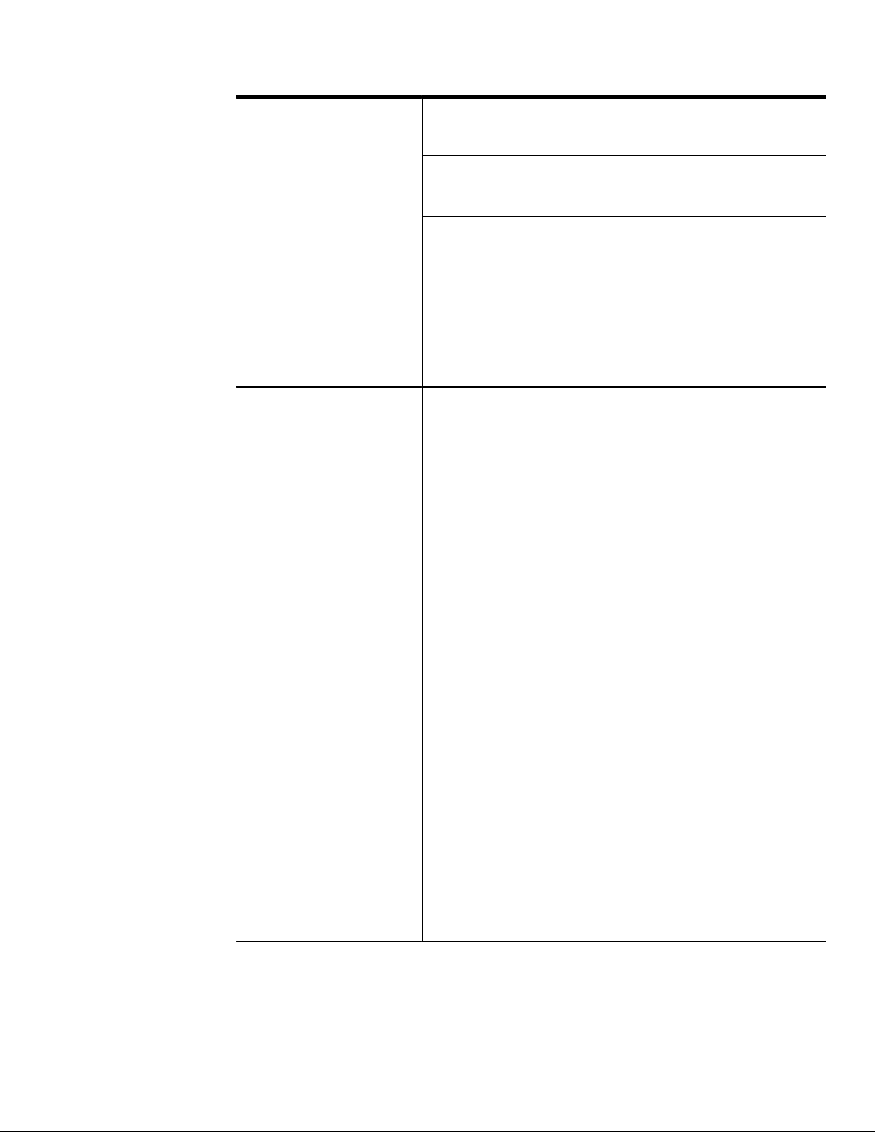
All three meters provide many features. Depending on
your meter type, all features described in this manual may
not apply.
The following list provides a comparison of the features
between meters.
Feature DMM912 DMM914 DMM916
40,000 display count D D D
Bargraph D D D
Centering and zooming D D
True RMS or average AC
measurements
Autorange D D D
Measurements
DC/AC voltage D D D
AC + DC voltage D D D
DC/AC current D D D
Resistance D D D
Frequency D D D
Diodes and capacitors D D D
Continuity D D D
Duty factor D D
Temperature D D
D D D
Decibel D
DMM912/914/916 1–5

Feature DMM916DMM914DMM912
AC volts and amps with Hz
display
Measurement hold D D D
Peak hold D
Minimum, maximum, and average
values
M/M/A time stamp D D
Delta mode D D D
HI/LO limits D D
Memory store and recall D D D
Backlight D
Automatic fuse verification D D D
Improper input connection
D D D
D D D
D D
warning
DMM912/914/9161–6

Front Panel Overview
4
3
2
1
1 Input connectors.
2 Measurement function dial. White labels are the initial
setting; blue labels are selected with the blue button.
3 Buttons, in conjunction with the dial, select instrument
functions.
4 LCD display with dual numeric readout.
DMM912/914/916 1–7

Display indicators
234 5
1
15
14
13
12
11 10
1
Auto range indicator
2 True RMS voltage indicator
3 Hold indicator
4 Auto Hold indicator
6
7
8
9
5 Peak Hold indicator
6 Upper display unit indicators
7 Main display unit indicators
8 Zoom indicator for bar graph
9 Diode check indicator
10 Maximum, Minimum, Maximum – Minimum, and
Average indicators
11 AC, DC, and AC+ DC voltage indicators
12 Battery indicator (low battery)
13 Memory indicator
DMM912/914/9161–8

14 High voltage input warning (>42 VDC, 30 VAC
15 Continuity indicator
Indicator Unit Indicator Unit
V Volts micro
A Amperes n nano
F Farad m milli
Hz Hertz M mega
min minute k kilo
_ F Fahrenheit delta
_ C Celsius % percent
ohm dB / dBm decibel
(1 V / 1 mV ref)
RMS
)
DMM912/914/916 1–9

Buttons
The blue button toggles between dual functions (white or
blue) located on the dial. It also exits the Setup mode.
Blue
button
STORE. The meter stores the present reading in memory
and the mem indicator is displayed momentarily. Use
RECALL to display the stored reading.
NOTE. The memory is erased anytime the meter
turns off.
SETUP. This button displays and scrolls through the user
adjustable menu items. Refer to page 1–14 for the Setup
menu functions.
BAR. This button scrolls through the types of bargraph
displays.
Zero at left
Zero at left, graph zoomed 10,
displayed
Zero at center
Zero at center (graph zoomed 10,
displayed)
Bar off
DMM912/914/9161–10

HOLD. This button toggles the hold mode on and off.
With hold on, the instrument beeps, freezes the display,
and displays the
RANGE. This button selects the manual ranging mode and
indicator.
then selects the range. The indicator turns off.
Press and hold the RANGE button for two seconds to
return the multimeter to auto-range mode (or turn the
dial).
M/M/A. This button scrolls through the MIN, MAX, MAX
– MIN, and AVG functions. Elapsed time from beginning
of test to the latest event appears in the upper display.
Events must be stable for 100 ms. The warning beeper
signals if the function is not applicable. Refer to page
1–34 for more details about these functions.
NOTE. You may want to adjust the auto power off
time limit. Refer to page 1–32 about auto power
off.
DMM912/914/916 1–11

Shifted buttons
The gold button shifts the button functions to the gold
labels. GOLd is displayed while shift is activated.
Gold
button
LIGHT. Push to activate the LCD backlight. Press the gold
button twice or hold down until the light turns on. Repeat
to turn off. Refer to page 1–15 about auto off time
adjustment.
HI/LO. Push to put the meter in a comparison mode,
comparing present readings to high and low limits
defined in the Setup menu. The beeper signals pass or
fail.
RECALL. Push to display the memory information. The
mem indicator appears in the display. Press again to
return to the set function display.
RESET. Push to set the minimum, maximum, average, and
peak hold values to the displayed measurement. This also
sets the timer to zero.
DMM912/914/9161–12

/ %. Push to enter the delta display mode, displaying the
difference (delta) between the measured value and a
reference value. The reference value is set when entering
Delta mode or using the Setup function. The difference is
displayed in the measurement units or as a percent
(selected by repeating the / % button press).
AUTO H. Hold mode is activated when a stable reading is
first achieved.
DIGITS. Push to toggle the display count between 40,000
and 4,000. The low count provides a faster response.
PEAK H . Peak hold operates similar to M/M/A except that
events as fast as 1 ms are captured and average values are
not available. The
indicator appears in the display.
Peak hold disables the bargraph. Peak hold operates for
DC volts.
DMM912/914/916 1–13

Setup buttons
SETUP. Push to display and scroll through a list of menu
prompts. Use these menus to adjust the meter operation or
sets values for various operations. Turning the meter off
does not affect saved setups.
. Scrolls left through the digits and polarity for selec-
tion.
. Scrolls right through the digits for selection.
+. Increases selected digit values or toggles default
settings.
–. Decreases selected digit values or toggles default
settings.
EXIT SETUP. Push to exit the setup mode, applying the
changes and saving them as new defaults. Turn the dial to
exit the setup mode, cancelling all changes.
DMM912/914/9161–14

The following table lists the prompts and a brief description of their action/purpose.
Display
prompt
1
rEF
Change the reference value (from the automatically
Parameter
set value) for delta measurements
HI L High limit
LO L Low limit
AG Average ACV or T rue RMS ACV
dB dBm or dB
bEEP Beeper ON/OFF
POFF
Auto power off time adjustment
2
bOFF Auto backlight off time adjustment
5060 50 or 60 Hz noise suppression
HAZ Hazard warning indicator off
1
2
Displayed only if Delta mode is active.
HI/LO, continuity, and probe input beepers are not
affected.
DMM912/914/916 1–15

Rotary dial functions
OFF. Turns the power off and erases display memory.
V / dBm / Hz. AC voltage measurements. Blue button
toggles upper readout between frequency and dBm (dB).
V . DC voltage measurements.
mV . High resolution DC voltage measurements for
voltages less than 400 mV.
AC + DC. Computes a true RMS voltage measurement
based on both the AC and DC components of the input
signal.
Hz / % DF. Frequency measurements. Blue button toggles
display reading to duty factor.
DMM912/914/9161–16

W / LV. Resistance measurements. Blue button toggles to a
low voltage source resistance measurement mode useful
for checking in-circuit components.
/ . Continuity checks. Blue button toggles to diode
check mode.
. Capacitance measurements.
mA . Current measurements up to 4,000 A. Blue
button toggles between DC and AC.
mA . Current measurements up to 400 mA. Blue button
toggles between DC and AC.
A . Current measurements of less than 10 A (20 A for
30 seconds). Blue button toggles between DC and AC.
_C / _F. Temperature measurements. Blue button toggles
between Celsius and Fahrenheit. Ambient temperature is
displayed in the upper readout.
DMM912/914/916 1–17

Input connectors
_C V W . Input connector for volts, ohms, frequency,
continuity, temperature, capacitance, and diode measurements.
COM. Common connector (ground reference). All mea-
surements are referenced to this connector.
WARNING. To avoid personal injury and product
damage, do not exceed more than a 1000 VDC
potential between the _C V
input or
between the COM connector or between earth
ground and these connectors.
Maximum open circuit voltage for the A mA
and A connectors is 600 V.
DMM912/914/9161–18

A mA. Input connector for current measurements up to
400 mA.
A. Input connector for current measurements up to 10 A
(20 A for 30 seconds).
Measurements above 10 A are possible with the follow-
ing restrictions:
H The maximum measurable current is 20 A.
H Limit measurements above 10 A to 30 seconds.
CAUTION. Limit large current measurements (10
to 20 A) to 30 seconds and allow two minutes of
cooling between measurements.
Do not connect to circuits with >600 V.
DMM912/914/916 1–19

Operating Basics
Before you take any of the measurements described in
this section, follow these steps to take the best measurements and avoid damaging the meter.
1. For improved accuracy, allow the meter to stabilize for
30 seconds after turning on the power.
2. Disconnect the test leads from the measurement points
when you select or change a measurement function.
3. Observe the safe test lead connections method on page
1–21 when removing the test leads from the meter.
4. Always disconnect power to the circuit when you
measure resistance, capacitors, check diodes, or check
continuity within the circuit.
Unstable or incorrect measurements may be displayed
when the meter is used near a circuit that emits electromagnetic waves.
DMM912/914/9161–20

Safe test lead connections
To safely disconnect the test leads from the meter, first
disconnect all test leads from the circuit being tested, then
disconnect the leads from the input connectors.
WARNING. To prevent electrical shock, do not
insert unnecessary test leads or metal pins into
the A mA and A connectors. Voltages applied to
the COM connector may be present at all other
input connectors.
Only use the test leads supplied or r ecommended
(or their equivalent) with the meter. Refer to
Accessories on page 1–45.
DMM912/914/916 1–21

AC voltage measurements
1. Set dial.
2. Choose dBm
(dB) or Hz.
3. Connect leads.
Blue button
AC voltage source
The AC measurement provides a true RMS or average
measurement of an AC signal. Select average in the Setup
menu.
NOTE. Frequency measurement accuracy and
range is increased using the main Hz dial
setting.
DMM912/914/9161–22

DC voltage measurements
1. Set dial.
2. Connect leads.
<400 mV
<1000 V
DC voltage source
The 400 mV setting provides one range for measuring
small voltages.
DMM912/914/916 1–23

AC + DC measurements
1. Set dial.
2. Connect leads.
0 V
0 V
The AC + DC measurement provides a true RMS equivalent voltage reading of the combined AC and DC components of a signal.
The formula
VRMS VAC
2
VDC
2
is used to
calculate the RMS voltage.
DMM912/914/9161–24

Frequency measurements
1. Set dial.
2. Choose
frequency or
duty factor.
3. Connect leads.
Blue button
ClockGround
The duty factor displays the percent of the signal that is
high.
DMM912/914/916 1–25

Resistance measurements
1. Set dial.
2. Choose low
voltage output.
3. Connect leads.
CAUTION. Remove all power from the circuit
before connecting the test leads.
Blue button
LV setting reduces the maximum test voltage level to
0.4 V to avoid turning on semiconductor devices. Display
count changes to 4,000.
Remove individual components from circuitry for best
results.
DMM912/914/9161–26

Continuity checks
1. Set dial.
2. Connect leads.
CAUTION. Remove all power from the circuit
before connecting the test leads.
The beeper sounds if the resistance of the circuit is less
than 75 .
DMM912/914/916 1–27

Diode testing
1. Set dial.
2. Choose diode
test.
3. Connect leads.
Forward bias
Good = 0.4 to 0.9 V
Bad = 0 or OL
Reverse bias
Good = OL
Bad = <2.0 V
Blue button
Forward bias
Reverse bias
CAUTION. Remove all power from the circuit
before connecting the test leads.
Remove individual components from circuitry for best
results.
DMM912/914/9161–28
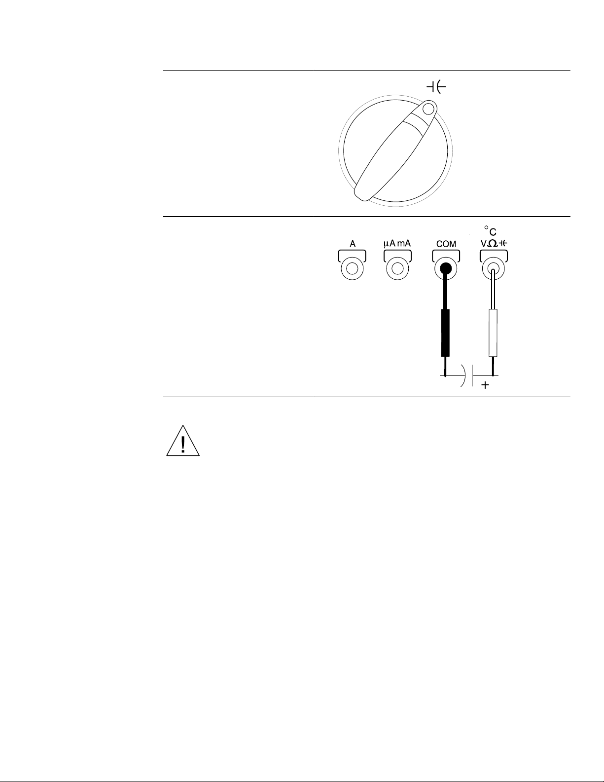
Capacitance measurements
1. Set dial.
2. Connect leads.
CAUTION. Remove all power from the circuit and
discharge capacitors before connecting the test
leads.
Remove capacitors from circuitry for best results. If your
software version is 1.90 or below, use SETUP mode to
select 60 Hz noise suppression for all capacitance measurements.
DMM912/914/916 1–29

Current measurements
4000 A
400 mA
A
1. Set dial.
2. Choose AC or
DC.
3. Connect leads.
<10
<
<400 mA
<10 A
Blue button
<
Current
source
CAUTION. Limit large current measurements (10
Load
to 20 A) to 30 seconds and allow two minutes of
cooling between measurements.
Do not connect to circuits with >600 V.
The AC measurement provides true RMS or average
measurements of symmetrical AC signals. Average is
selected in the Setup menu.
DMM912/914/9161–30

Temperature measurements
1. Set dial.
2. Choose Celsius
or Fahrenheit.
Blue button
3. Connect leads.
Thermocouple
probe adapter
Temperature
probe
This setting requires an optional temperature probe and
adapter. Refer to Accessories on page 1–45.
DMM912/914/916 1–31

Special Feature Descriptions
Auto power off
The auto power off automatically turns the meter off if no
controls or settings are changed within a set amount of
time. Turning the dial or pressing the gold or blue buttons
restores power . The meter returns to the default condition
of the dial position.
Use the Setup menu to adjust the auto power off delay.
You can disable the auto power off by pressing the blue
button when turning the dial from its off position.
Hold
Hold freezes the display to allow removal of the probes
from the test points without losing the reading.
Minimum and maximum values are still acquired while in
hold mode.
Auto hold
Auto hold operates like Hold except that the display
freezes whenever the reading stabilizes. The meter beeps
to indicate hold has been activated.
Auto fuse detection
The meter checks the integrity of the internal fuses
whenever they are needed for correct operation. If an
open fuse is detected, FUSE 1 or FUSE 2 is displayed
and two beeps sound.
DMM912/914/9161–32

Probe input guard
The meter beeps continuously and displays ProbE if a
probe is inserted in a current input connector and a
measurement other than current is selected.
Beeper
A single beep indicates correct operation; two beeps
indicate a warning or error condition. Use the Setup menu
to set the beeper mode on or off. Continuity checks and
the probe insertion guard are not affected by turning the
beeper off.
HI/LO
HI/LO mode allows you to set high and low limits that
the input is compared to. A single beep indicates the
measurement is within the limits; two beeps indicate a
value outside the limits. When outside the limits, either
HI or LO is indicated in the upper display.
Use the Setup menu to set the HI and LO limits. To retain
the new values, press EXIT SETUP.
Two beeps sound (error) under these conditions:
H Limits not set for the selected function or range
H LO is greater than or equal to HI
DMM912/914/916 1–33

MIN/MAX/AVG operation
The M/M/A button cycles through the operations listed
below. The upper readout displays the elapsed time from
the start of the test to the occurrence of the latest recorded
event (time stamp). Press RESET to restart all readings
and timer.
Live display MIN, MAX, and AVG indicators are displayed. The
display updates as new values are detected.
Display max MAX indicator is displayed and the value is the most
recent maximum value. The MIN indicator displays
momentarily if a new minimum value is detected.
Display min MIN indicator is displayed and the displayed value is
the most recent minimum value. The MAX indicator
displays momentarily if a new maximum value is
Display
max–min
Display
average
detected.
MAX–MIN indicator is displayed and the displayed
value is the most recent maximum value minus the
most recent minimum value. When new minimum or
maximum values are detected, the MIN or MAX
indicator is displayed momentarily.
AVG indicator is displayed and the average value of
all meter readings is displayed. The MIN or MAX
indicator is displayed momentarily when new values
are detected.
DMM912/914/9161–34

Battery and Fuse Replacement
9 V battery
Case top
FUSE 1
(600 V)
FUSE 2
(600 V)
Case bottom
15 A
1 A
W ARNING. Installing improper fuses can cause
injury and product damage.
DMM912/914/916 1–35

Specifications
All specifications are warranted unless noted typical and
apply to the DMM912, DMM914, and DMM916.
Stated accuracies are at 23_
C ± 5_ C at less than 75%
relative humidity and without the battery indicator
displayed.
General specifications
Characteristics
LCD display digits 4#@4 or 3#@4
Bargraph segments 40
Display count 40,000 or 4,000
Numeric update rate 1 time/sec (40,000 count)
Bargraph 20 times/sec
Polarity display Automatic
Description
4 times/sec (4,000 count)
Overrange display OL is displayed
Low voltage indicator Battery indicator
Automatic power-off time User selectable (default = 15 minutes)
Power source One 9 V dry cell battery
1–36 DMM912/914/916

General specifications (cont.)
Maximum inpu
Ma i u i pu u e
Accuracy
Auay
Characteristics Description
Maximum input voltage 1000 V (750 V AC) CAT II between V
and COM
Maximum floating voltage 1000 V (750 V AC) CAT II between
any terminal and earth ground
t current
400 mA between A mA and COM
10 A continuous between A and COM
(20 A for 30 seconds)
Maximum open circuit
voltage (current inputs)
600 V between A and COM and
between A mA and COM
Overload protection
A mA connector 1 A (600 V) fast blow fuse
A connector 15 A (600 V) fast blow fuse
V connector 1100 V
850 V
p
p
_C
Measurement characteristics
AC + DCV V
HzmV
Characteristics
Description
DC voltage
V ranges 4 V, 40 V, 400 V, 1000 V
mV range 400 mV
DMM912 DMM914 DMM916
(% + 1 count)
1
±0.2% ±0.1% ±0.06%
1–37DMM912/914/916

Measurement characteristics (cont.)
Characteristics Description
AC voltage
Ranges 4 V, 40 V, 400 V, 750 V
Accuracy
(% + 4 counts)
5
1
DMM912 DMM914 DMM916
50 to 100 Hz ±1.0% ±0.8% ±0.7%
>100 to 1 kHz
>1 kHz to 10 kHz
>10 kHz to 20 kHz
2
2
±2.5% ±2.0% ±1.5%
– – – ±3.5% ±2.5%
2
– – – – – – ±3.5%
Bandwidth DMM912 DMM914 DMM916
1 kHz 10 kHz 20 kHz
Crest factor 3 (Peaks limited to 1000 V)
Input impedance >10 M paralleled by <100 pF
AC + DC volts Same as AC (RMS) + 1.2% +
10 counts
3
Crest factor 3 (Peaks limited to 1000 V)
Input impedance >10 M paralleled by <100 pF
dBm
(typical)
dBv
(typical)
–15 dBm to +55 dBm
(0 dBm = 1 mW into 600 )
–80 dBv to +50 dBv
(0 dBv = 1 V
rms
)
1–38 DMM912/914/916

Measurement characteristics (cont.)
AC a
es
AC a DC a es
DC accuracy
DC a u a y
Compliance
es
C plia e l a es
Characteristics Description
Current
nd DC rang
4,000 mA, 400 mA, 10 A
20 A maximum for < 30 seconds
DMM912 DMM914 DMM916
(% + 1 count)
AC accuracy
(% + 8 counts)
Bandwidth (typical)
1
±0.5% ±0.4% ±0.3%
±1.2% ±0.9% ±0.9%
1
1 kHz
Resistance
Ranges
W ranges 400 W, 4 kW, 40 kW, 400 kW, 4 MW,
40 MW
LV ranges
2,3
4 kW, 40 kW, 400 kW, 4 MW, 40 MW
Accuracy DMM912 DMM914 DMM916
W (% + 1 count)
400 W range ±1% ±0.8% ±0.6%
4 MW range ±1% ±0.8% ±0.6%
40 MW range
LV (% + 1 count)
voltag
(typical)
Continuity threshold
1
3
2,3
±0.5% ±0.4% ±0.3%
±5% ±5% ±5%
±1% ±0.8% ±0.6%
1 V (W setting)
0.4 V (LV setting)
3
Beeper sounds when resistance is
approximately 75 W or less
1–39DMM912/914/916

Measurement characteristics (cont.)
Characteristics Description
Diode test
3
Test current (typical) 0.5 mA
Test voltage (typical)
3 V
Capacitance
Ranges 4 nF, 40 nF, 400 nF, 4 F, 40 F,
400 F, 4 mF, 40 mF
Accuracy
3
(% + 10 counts)
4 nF to 4 F
7
±1%
40 F to 40 mF ±3%
Frequency
4
Ranges 400 Hz, 4 kHz, 40 kHz, 400 kHz,
2 MHz
Accuracy
(% + 1 count)
6
1
400 Hz to 400 kHz ±0.01%
2 MHz ±0.15%
Sensitivity 0.5 V
p-p
Duty factor
Accuracy ±(0.1% + 0.05% per kHz) for 5 V
input
Range 15 Hz to 10 kHz (10% – 90% duty
factor)
1–40 DMM912/914/916

Measurement characteristics (cont.)
Characteristics Description
Temperature
Range –50_ C to +980_ C
Accuracy 2_C
Thermocouple type K
Peak measurements
3
Accuracy (DC volts) ±5% + 40 counts of the peak value of
a single 1 ms pulse
1
2
3
4
Multiply counts by 10 in 40,000 count mode.
750 V, 40 M–LV range unspecified.
4000 count mode only.
Upper display readout is limited to 10 kHz with reduced
accuracy.
5
6
7
>10% range, 4 V range > 1 V.
>5% range.
4 nF and 40 nF must use Delta mode.
Physical characteristics
Characteristic
Description
Dimensions (H W D) 32 mm 86 mm 185 mm
(without holster)
Weight (with battery) 370 g (13 oz.)
With holster 600 g (21.2 oz.)
1–41DMM912/914/916

Environmental characteristics
Inpu
Ipu ai
Characteristic
Description
Temperature
Operating 0 to +50_ C
Non-operating
–20 to +60_ C
(storage)
Humidity (operating) <80%
Altitude
Operating 2,000 m (6562 ft.)
Non-operating 12,300 m (40354 ft.)
Vibration
Operating 2.66 g
, 5 to 500 Hz, 3 axes
RMS
(10 minutes each)
Non-operating 3.48 g
, 5 to 500 Hz, 3 axes
RMS
(10 minutes each)
Certifications and compliances
Characteristic
Description
Certifications Listed UL3111–1 and CAN/CSA
C22.2 No. 1010–1
t rating
1000 V DC Category II
600 V DC Category III
750 V AC Category II
600 V AC Category III
1–42 DMM912/914/916

Certifications and compliances (cont.)
Ove
e
EC Declarati
f
Characteristic
rvoltag
category
Pollution Degree 2 Do not operate in environments where
on o
Conformity
Description
CAT III: Distribution level mains, fixed
installation
CAT II: Local level mains, appliances,
portable equipment
CAT I: Signal level, special equipment or
parts of equipment, telecommunication,
electronics
conductive pollutants may be present.
Meets the intent of Directive 89/336/EEC for
Electromagnetic Compatibility and Low
V oltage Directive 73/23/ECC as ammended
by 93/68/EEC for Product Safety. Compliance
was demonstrated to the following specifications as listed in the official Journal of the
European Communities:
EN 55011 Class B: Radiated Emissions
EN 50082–1 Immunity:
IEC 801–2 Electrostatic Discharge
IEC 801–3 RF Electromagnetic
Field
EN 61010-1/A2 Safety requirements for
electrical equipment for
measurement, control,
and laboratory use
1–43DMM912/914/916

ATL01 Test lead set certifications and compliances
Characteristic
Certifications CAN/CSA-C22.2 No. 1010.1-M92;
Rating 1000 V CAT III 10 A
Manufacturing site Taiwan
Description
CAN/CSA-C22.2 No. 1010.2.031-94;
UL3111-1; Marked for the Low Voltage CE
Directive.
1–44 DMM912/914/916

Accessories
Replaceable parts Part Number
Test leads (1 red, 1 black) A TL01
Holster 118-9484-XX
Instructions
English, German,
French, Spanish
English, Japanese,
Chinese, Korean
One dry cell battery 9 V, NEDA 1604, or equivalent
Fuses
15 A, 600 V 159-0287-00, KLK 15 A 600 V
1 A, 600 V 159-0337-00, BLS 1 A 600 V
Optional accessories Part Number
Temperature probes Temperature probes require the
070-9791-XX
070-9792-XX
RMS
RMS
thermocouple adapter A TK01
A TP01 Bead probe
Current probe A603 150 Amp, AC current
Deluxe lead set ATLDX1
Soft carrying case AC12
1–45DMM912/914/916

General Care and Cleaning
Protect the meter from adverse weather conditions. The
meter is not waterproof.
Do not expose the LCD display to direct sunlight for long
periods of time.
CAUTION. To avoid damage to the meter, do not
expose it to sprays, liquids, or solvents.
Clean the exterior of the meter by removing dust with a
lint-free cloth. Use care to avoid scratching the clear
plastic display filter.
For further cleaning, use a soft cloth or paper towel
dampened with water. You can use a 75% isopropyl
alcohol solution for more efficient cleaning.
CAUTION. To avoid damage to the surface of the
meter, do not use abrasive or chemical cleaning
agents.
1–46 DMM912/914/916

Instructions d’utilisation des
multimètres numériques
DMM912, DMM914 & DMM916
070-9791-01
2

Copyright Tektronix, Inc. Tous droits réservés.
Les produits Tektronix sont protégés aux Etats-Unis et à
l’étranger par des brevets déjà obtenus ou dont la demande a été
déposée. Les informations contenues dans ce manuel
remplacent toute information publiée dans les documents
précédents. Les privilèges de changement de prix et de
spécifications sont réservés.
Imprimé à Hong Kong.
Tektronix, Inc., P.O. Box 1000, Wilsonville, OR 97070–1000
TEKTRONIX, TEK et TekTools sont des marques déposées de
Tektronix, Inc.

RESUME DE LA GARANTIE
Tektronix garantit le présent produit contre tout défaut de
matériaux ou de main-d’oeuvre pendant une période de
trois ans, à compter de la date d’achat auprès d’un
vendeur agréé par Tektronix. Si une déficience vient à se
manifester au niveau du produit ou de l’écran à cristaux
liquides pendant cette période de garantie, Tektronix
s’engage à procéder, à sa meilleure convenance, à la
réparation ou au remplacement du produit déficient
comme le décrit le texte complet de la garantie.
Pour un dépannage ou l’obtention du texte complet de la
garantie, veuillez contacter votre distributeur Tektronix.
LE PRESENT RESUME DE GARANTIE ET LE
TEXTE DE GARANTIE APPLICABLE SONT
CONFERES PAR TEKTRONIX EN LIEU ET PLACE
DE TOUTE AUTRE GARANTIE, EXPRESSE OU
IMPLICITE, Y COMPRIS TOUTE GARANTIE
D’APTITUDE A LA COMMERCIALISATION OU
D’ADEQUATION A UNE UTILISATION
SPECIFIQUE. TEKTRONIX NE POURRA EN
AUCUN CAS ETRE TENU RESPONSABLE DE
DOMMAGES INDIRECTS, SPECIAUX OU
CONSEQUENTS.


Table des matières
Sécurité 2–3. . . . . . . . . . . . . . . . . . . . . . . . . . . . . . . . .
Description du produit 2–5. . . . . . . . . . . . . . . . . . . . .
Vue générale du panneau avant 2–7. . . . . . . . . . . . . . .
Indicateurs d’affichage 2–8. . . . . . . . . . . . . . . . . . .
Touches 2–10. . . . . . . . . . . . . . . . . . . . . . . . . . . . . .
Touches permutables 2–12. . . . . . . . . . . . . . . . . . . .
Touches de configuration 2–14. . . . . . . . . . . . . . . . . .
Fonctions du cadran rotatif 2–16. . . . . . . . . . . . . . . .
Connecteurs d’entrée 2–18. . . . . . . . . . . . . . . . . . . .
Fonctionnement de base 2–20. . . . . . . . . . . . . . . . . . . .
Connexions de sécurité des cordons de test 2–21. . . .
Mesures de tension en courant alternatif 2–22. . . . . . .
Mesures de tension en courant continu 2–23. . . . . . . .
Mesures en courant alternatif et continu 2–24. . . . . . .
Mesures de fréquence 2–25. . . . . . . . . . . . . . . . . . . .
Mesures de résistance 2–26. . . . . . . . . . . . . . . . . . .
Contrôles de continuité 2–27. . . . . . . . . . . . . . . . . . .
Test de diode 2–28. . . . . . . . . . . . . . . . . . . . . . . . . .
Mesures de capacitance 2–29. . . . . . . . . . . . . . . . . .
Mesures d’intensité 2–30. . . . . . . . . . . . . . . . . . . . . .
Mesures de température 2–31. . . . . . . . . . . . . . . . . .
DMM912/914/916
2–1

Description des commandes spéciales 2–32. . . . . . . . .
Arrêt automatique 2–32. . . . . . . . . . . . . . . . . . . . . . .
Maintien 2–32. . . . . . . . . . . . . . . . . . . . . . . . . . . . . .
Maintien automatique 2–32. . . . . . . . . . . . . . . . . . . .
Détection de fusible automatique 2–32. . . . . . . . . . . .
Dispositif de protection d’entrée de sonde 2–33. . . . . .
Signal sonore 2–33. . . . . . . . . . . . . . . . . . . . . . . . . .
HI/LO Elévé/Bas 2–33. . . . . . . . . . . . . . . . . . . . . . . .
Commande MIN/MAX/AVE 2–34. . . . . . . . . . . . . . . .
Changement de pile et de fusible 2–35. . . . . . . . . . . . .
Caractéristiques techniques 2–36. . . . . . . . . . . . . . . . .
Accessoires 2–45. . . . . . . . . . . . . . . . . . . . . . . . . . . . .
Entretien général et nettoyage 2–46. . . . . . . . . . . . . . . .
2–2 DMM912/914/916

Sécurité
Lisez attentivement les consignes de sécurité ci-dessous
concernant la prévention des blessures corporelles et des
dommages à l’appareil ou à tout autre produit connecté.
ATTENTION. Ces indications signalent des
conditions ou actions qui peuvent provoquer des
dommages au matériel ou à d’autres
équipements.
AVERTISSEMENT. Ces indications signalent des
conditions ou actions dangereuses pour
l’utilisateur tels que des risques de blessure ou
un danger de mort.
Symboles apparaissant sur le matériel
Consulter
de manuel
Isolement
double
Haute
tension
Précautions particulières
Utiliser le fusible adéquat. Pour prévenir des risques
d’incendie, utilisez uniquement le type de fusible et la
tension nominale indiqués pour cet appareil.
Ne pas utiliser sans capots. Pour prévenir les risques de
blessure, n’appliquez pas de tension ou courant sans les
capots de protection en place.
Risques de surcharge électrique. N’appliquez jamais une
tension nominale à un connecteur qui serait supérieure à
la plage spécifiée.
DMM912/914/916
2–3

Risques d’électrocution. Pour prévenir les risques de
blessure ou de mort, ne pas connecter ou déconnecter les
sondes ou cordons de test lorsqu’ils sont branchés à une
alimentation électrique.
Ne pas utiliser dans un environnement humide. Pour
prévenir les décharges électriques, n’utilisez jamais
l’appareil dans des conditions d’humidité.
2–4
DMM912/914/916

Description du produit
Les trois multimètres possèdent de nombreuses
caractéristiques. Selon le type de votre appareil, les
caractéristiques décrites dans ce manuel peuvent ne pas
s’y appliquer.
La liste suivante fournit des comparaisons entre les
caractéristiques des différents multimètres.
Caractéristique DMM912 DMM914 DMM916
Affichage de 40.000 unités D D D
Histogramme D D D
Centrage et zoom D D
Mesures en valeur efficace réelle
ou courant alternatif moyen
Gamme automatique D D D
Mesures
Tension c.c./c.a. D D D
Tension c.a. + c.c. D D D
Intensité c.c./c.a. D D D
Résistance D D D
Fréquence D D D
Diodes et condensateurs D D D
Continuité D D D
Coefficient d’utilisation D D
Température D D
D D D
Décibel D
DMM912/914/916 2–5

Caractéristique DMM916DMM914DMM912
V olts c.a. et ampères avec
affichage en Hz
Maintien de la mesure D D D
Maintien de la crête D
Valeurs moyennes, maximales et
minimales
Estampage de l’heure M/M/A D D
Mode delta D D D
Limites élevées/basses (HI/LO) D D
Enregistrement en mémoire et
rappel à l’écran
Rétro éclairage D
Vérification automatique du
fusible
D D D
D D D
D D D
D D
Avertissement de connexion
d’entrée inadéquate
D D D
DMM912/914/9162–6

V ue générale du panneau avant
4
3
2
1
1 Connecteur d’entrée.
2 Cadran des fonctions de mesure. Les étiquettes
blanches indiquent le paramètre initial; les étiquettes
bleues sont sélectionnées avec la touche bleue.
3 Les touches, en conjonction avec le cadran rotatif,
sélectionnent les fonctions de l’appareil.
4 Affichage par cristaux liquides avec double lecture
numérique.
DMM912/914/916 2–7

Indicateurs d’affichage
234 5
1
15
14
13
12
11 10
1
Indicateur de gamme automatique
2 Indicateur de valeur efficace de tension réelle
3 Indicateur de maintien
4 Indicateur de maintien automatique
9
6
7
8
5 Indicateur de maintien de crête
6 Indicateurs de l’unité d’affichage supérieure
7 Indicateur de l’unité d’affichage principale
8 Indicateur de zoom de l’histogramme
9 Indicateur de test de diode
10 Indicateurs Minimum, Maximum, Maximum –
Minimum et Moyenne
11 Indicateurs de tension c.a., c.c., c.a. + c.c.
12 Indicateur de batterie (batterie faible)
13 Indicateur de mémoire
DMM912/914/9162–8

14 Avertissement d’entrée de haute tension (>42 V c.c.,
30 V c.a.eff)
15 Indicateur de continuité
Indicateur Unité Indicateur Unité
V Volts micro
A Ampères n nano
F Farad m milli
Hz Hertz M mega
min minute k kilo
_ F Fahrenheit delta
_ C Celsius % pour-cent
ohm dB / dBm décibel
(réf. 1 v / 1 mV)
DMM912/914/916 2–9

Touches
La touche bleue bascule entre deux fonctions (blanche ou
bleue) situées sur le cadran rotatif. Elle permet également
de sortir du mode de configuration (Setup).
Touche
bleue
STORE.
Le multimètre enregistre la lecture courante en
mémoire et l’indicateur de mémoire s’affiche
momentanément. Utilisez RECALL pour afficher la
lecture enregistrée.
NOTE. La mémoire est effacée à lorsque le
multimètre est éteint.
SETUP. Cette touche affiche et fait défiler les articles du
menu réglable par l’utilisateur. Référez-vous à la page
2–14 pour connaître les fonctions du menu de
configuration (Setup).
BAR. Cette touche fait défiler les différents types
d’affichages d’histogrammes.
Zéro à gauche
Zéro à gauche, tableau zoomé X 10, affichage
Zéro au centre
Zéro au centre (tableau zoomé X 10, affichage
Histogramme éteint
DMM912/914/9162–10
)

HOLD. Cette touche bascule afin d’activer et de désactiver
le mode de maintien. Lorsque la fonction de maintien est
activée, l’appareil émet un signal sonore, bloque
l’affichage et affiche l’indicateur
RANGE. Cette touche permet de choisir le mode de
.
sélection de gamme manuel et puis de sélectionner la
gamme. L’indicateur
s’éteint. Appuyez et
maintenez la touche RANGE appuyée pendant deux
secondes pour remettre le multimètre en mode de
sélection de gamme automatique (ou tournez le cadran
rotatif).
M/M/A. Cette touche permet de faire défiler les fonctions
MIN, MAX, MAX – MIN et AVG. Le temps écoulé entre
le début du test et le dernier événement apparaît sur
l’affichage supérieur . Les événements doivent être stables
pendant 100 ms. Le signal d’avertissement retentit si la
fonction n’est pas applicable. Référez-vous à la page
2–34 pour obtenir des détails supplémentaires à propos de
ces fonctions.
NOTE. Vous pouvez choisir de régler la durée
d’arrêt automatique. Référez-vous à la page
2–32 à propos de l’arrêt automatique.
DMM912/914/916 2–11

Touches permutables
La touche or permet de permuter les fonctions de cette
dernière sur l’étiquette or. GOLD est affiché lorsque la
permutation est activée.
Touche
or
LIGHT. Appuyez sur cette touche pour activer le rétro
éclairage à cristaux liquides. Appuyez deux fois sur la
touche or ou maintenez-la appuyée jusqu’à ce que
l’éclairage s’allume. Répétez la procédure pour l’éteindre.
Référez-vous à la page 2–15 à propos du réglage de
l’arrêt automatique.
HI/LO. Appuyez sur cette touche pour mettre le multimètre
en mode de comparaison. Cette fonction permet de
comparer les lectures présentes avec les limites élevées et
basses définies dans le menu de configuration. Le signal
sonore indique un succès ou un échec.
RECALL. Appuyez sur cette touche pour afficher
l’information relative à la mémoire. L’indicateur de
mémoire apparaît à l’écran. Appuyez à nouveau pour
retourner à l’affichage de la fonction.
RESET. Appuyez pour régler les valeurs de maintien de
crête, moyennes, maximales et minimales à la mesure
affichée. La minuterie est remise à zéro par la même
occasion.
DMM912/914/9162–12

/ %. Appuyez sur cette touche pour activer le mode
d’affichage delta, La différence (delta) entre la valeur
mesurée et la valeur de référence apparaîtra alors. La
valeur de référence est déterminée lorsque vous entrez le
mode delta ou utilisez la fonction de configuration. La
différence est affichée dans les unités de mesure ou en tant
que pourcentage (sélectionné en appuyant une deuxième
fois sur la touche / %).
AUTO H. Le mode de maintien est activé lorsqu’une
première lecture stable est obtenue.
DIGITS. Appuyez sur cette touche pour faire passer la
lecture de 40.000 à 4.000. Une lecture inférieure permet
une réponse plus rapide.
PEAK H. La touche de maintien de crête fonctionne de
façon similaire à M/M/A sauf que des événements aussi
rapides que 1 ms sont capturés et les valeurs moyennes ne
sont pas disponibles. L’indicateur
apparaît à l’écran.
Le maintien de crête désactive l’histogramme. La touche
de maintien de crête fonctionne pour les volts.
DMM912/914/916 2–13

Touches de configuration
SETUP. Appuyez sur cette touche et faites défiler une liste
de messages de menu. Utilisez ces menus pour régler le
fonctionnement du multimètre ou régler les valeurs pour
différentes opérations. Les configurations sauvegardées
restent inchangées lorsque le multimètre est désactivé.
. Défile vers la gauche pour sélectionner les chiffres et la
polarité.
. Défile vers la droite pour sélectionner les chiffres.
+. Augmente les valeurs numériques sélectionnées ou
bascule pour afficher les configurations par défaut.
–. Diminue les valeurs numériques sélectionnées ou
bascule pour afficher les configurations par défaut.
EXIT SETUP. Appuyez sur cette touche pour sortir du mode
de configuration en appliquant les nouveaux
changements et en les sauvegardant comme
configurations par défaut. Tournez le cadran rotatif pour
sortir du mode de configuration et annuler tous les
changements.
DMM912/914/9162–14

Le tableau suivant donne une liste des messages et une
brève description de leur action/utilité.
Message
affiché
1
rEF
Modifie la valeur de référence (de la valeur
Paramètre
déterminée automatiquement) pour des mesures
delta
HI L Limite supérieure
LO L Limite inférieure
AG Tension moyenne en courant alternatif ou tension
efficace réelle en courant alternatif
dB dBm ou dB
bEEP Signal sonore activé/désactivé
POFF Réglage du délai de l’arrêt automatique
bOFF
Réglage du délai de l’arrêt automatique du rétro
2
éclairage
5060 Suppression du bruit de 50 ou 60 Hz
HAZ Indicateur d’avertissement de danger éteint
1
2
Affiché uniquement si le mode delta est activé.
Les signaux sonores HI/LO, continuité et entrée de
sonde restent inchangés.
DMM912/914/916 2–15

Fonctions du cadran rotatif
OFF. Coupe l’alimentation électrique et efface la mémoire
d’affichage.
V / dBm / Hz. Mesures de la tension en courant alternatif.
La touche bleue fait basculer la lecture supérieure entre la
fréquence et dBm (dB).
V . Mesure la tension en courant continu.
mV . Mesure la tension en courant continu haute
résolution pour les tensions inférieures à 400 mV.
AC + DC. Calcule une mesure en tension efficace réelle
suivant les composants c.a. et c.c. du signal d’entrée.
Hz / % DF. Mesure la fréquence. La touche bleue fait
basculer l’affichage sur le coefficient d’utilisation.
DMM912/914/9162–16

W / LV. Mesure la résistance. La touche bleue bascule sur
un mode de mesure de résistance d’une source de faible
tension utile pour la vérification des composants internes.
/ . Contrôle la continuité. La touche bleue bascule
sur le mode de test de diode.
. Mesure la capacité.
mA . Mesure le courant allant jusqu’à 4.000 A. La
touche bleue bascule entre c.c. et c.a..
mA . Mesure le courant allant jusqu’à 400 mA. La
touche bleue bascule entre c.c. et c.a..
A . Mesure l’intensité inférieure à 10 A (20 A pendant
30 secondes). La touche bleue bascule entre c.c. et c.a..
_C / _F. Mesure la température. La touche bleue bascule
entre Celsius et Fahrenheit. La température ambiante est
affichée sur l’écran supérieur.
DMM912/914/916 2–17

Connecteurs d’entrée
_C V W . Connecteur d’entrée pour volts, ohms,
fréquence, continuité, température, capacité et mesures de
diode.
COM. Connecteur commun (la terre étant la référence). Ce
connecteur sert de référence à toutes les mesures.
AVERTISSEMENT. Afin d’éviter des blessures
corporelles ou un endommagement à l’appareil,
ne dépassez pas un potentiel de 1000 V c.c. entre
l’entrée _C V W
, le connecteur COM ou la
terre et ces connecteurs.
La tension à vide maximale pour des connecteurs
mA mA et A est de 600 V.
DMM912/914/9162–18

A mA. Connecteur d’entrée pour les mesures d’intensité
inférieures à 400 mA.
A. Connecteur d’entrée pour les mesures d’intensité
inférieures à 10 A (20 A pendant 30 secondes).
Des mesures supérieures à 10 A sont possibles avec les
restrictions suivantes :
H L’intensité mesurable maximale est de 20 A.
H Les mesures supérieures à 10 A sont limitées à 30
secondes.
ATTENTION. Limitez les mesures d’intensité
élevées (entre 10 et 20 A) à 30 secondes et laissez
refr oidir pendant 2 minutes entre chaque mesure.
Ne pas connecter à des circuits de >600 V.
DMM912/914/916 2–19

Fonctionnement de base
Avant de commencer la prise de mesures comme le décrit
cette section, veuillez suivre ces quelques points afin de
prendre des mesures correctes et éviter tout dommage à
l’appareil.
1. Pour une exactitude optimale, laissez au multimètre
une période de stabilisation de 30 secondes après la
mise sous tension.
2. Déconnectez les cordons de test des points de mesure
avant de sélectionner ou changer une fonction de
mesure.
3. Observez la méthode de connexion des cordons de test
à la page 2–21 avant de retirer ces derniers de
l’appareil.
4. Coupez toujours l’alimentation du circuit avant de
mesurer la résistance ou les condensateurs ou lorsque
vous testez les diodes ou vérifiez la continuité interne
du circuit.
L’affichage de mesures erronées ou instables peut être le
résultat de l’utilisation du multimètre près d’un circuit qui
émet des ondes électromagnétiques.
DMM912/914/9162–20

Connexions de sécurité des cordons de test
Afin de déconnecter les cordons de test du multimètre,
déconnectez d’abord tous les cordons de test du circuit
testé, puis déconnectez les cordons des connecteurs
d’entrée.
AVERTISSEMENT. Afin d’éviter une décharge
électrique, n’insérez pas de cordon de test ni de
broche métallique inutilement dans les
connecteurs A mA et A. Les tensions
appliquées au connecteur COM peuvent être
présentes à tous les autres connecteurs d’entrée.
N’utilisez que les cordons de test livrés avec le
multimètre ou recommandés pour votre appareil
(ou leur équivalent). Référez-vous à la partie
Accessoires à la page 2–45.
DMM912/914/916 2–21

Mesures de tension en courant alternatif
1. Réglez le
cadran.
2. Sélectionnez
dBm (dB) ou
Hz.
3. Connectez les
sondes.
Touche
bleue
Source de tension c.a.
La mesure en courant alternatif détermine la valeur
efficace réelle ou moyenne d’un signal c.a.. Sélectionnez
la moyenne dans le menu de configuration.
NOTE. L’exactitude et la gamme de la mesure de
fréquence augmente à l’aide du paramètre
principal Hz sur le cadran.
DMM912/914/9162–22

Mesures de tension en courant continu
1. Réglez le
cadran.
<400 mV
<1000 V
2. Connectez les
sondes.
Source de tension c.c.
Le paramètre 400 mV fournit une gamme pour permettre
la mesure des faibles tensions.
DMM912/914/916 2–23

Mesures en courant alternatif et continu
1. Réglez le
cadran.
2. Connectez les
sondes.
0 V
0 V
La mesure c.a. + c.c. fournit une lecture de tension
efficace équivalente réelle pour les composants mixtes c.a.
et c.c. d’un signal.
L’équation
Veff
Vc.a.
2
Vc.c.
2
est utilisée pour
calculer la tension efficace.
DMM912/914/9162–24

Mesures de fréquence
1. Réglez le
cadran.
2. Sélectionnez la
fréquence ou le
coefficient
d’utilité.
3. Connectez les
Touche
bleue
sondes.
PenduleTerre
Le coefficient d’utilité affiche le pourcentage élevé du
signal.
DMM912/914/916 2–25

Mesures de résistance
1. Réglez le
cadran.
2. Sélectionnez la
sortie de faible
tension.
3. Connectez les
sondes.
ATTENTION. Coupez l’alimentation du circuit
avant de connecter les cordons de test.
Touche
bleue
Le paramètre LV réduit le niveau de tension de test
maximum à 0,4 V afin d’éviter la mise en marche des
appareils semi-conducteurs. La lecture affichée devient
4.000.
Retirez les composants individuels du circuit afin
d’obtenir les meilleurs résultats possibles.
DMM912/914/9162–26

Contrôles de continuité
1. Réglez le
cadran.
2. Connectez les
sondes.
ATTENTION. Coupez l’alimentation du circuit
avant de connecter les cordons de test.
Le signal sonore retentit si la résistance du circuit est
inférieure à 75 .
DMM912/914/916 2–27

Test de diode
1. Réglez le
cadran.
2. Sélectionnez le
test de diode.
3. Connectez les
sondes.
Polarisation avant
Bon = de 0,4 à 0,9 V
Mauvais = 0 ou OL
Polarisation inverse
Bon = OL
Touche
bleue
Polarisation
avant
Polarisation
inverse
Mauvais = <2,0 V
ATTENTION. Coupez l’alimentation du circuit
avant de connecter les cordons de test.
Retirez les composants individuels du circuit afin
d’obtenir les meilleurs résultats possibles.
DMM912/914/9162–28

Mesures de capacitance
1. Réglez le
cadran.
2. Connectez les
sondes.
ATTENTION. Attention. Couper l’alimentation du
circuit et des condensateurs de décharge avant
de brancher les conducteurs de test.
Pour obtenir les meilleurs résultats possibles, retirer les
condensateurs du circuit. Si la version du logiciel est 1.90
ou antérieure, utiliser le mode SETUP pour sélectionner
la suppression du bruit de 60 Hz pour toutes les mesures
de capacitance.
DMM912/914/916 2–29

Mesures d’intensité
4000 A
400 mA
A
1. Réglez le
cadran.
2. Sélectionnez
c.a. ou c.c..
3. Connectez les
sondes.
<10
<
<400 mA
<10 A
Touche
bleue
<
Source
Charge
d’alimentation
ATTENTION. Limitez les mesures d’intensité
élevées (entre 10 et 20 A) à 30 secondes et laissez
refr oidir pendant 2 minutes entre chaque mesure.
Ne connectez pas à des circuits >600 V.
Les mesures c.a. donnent des valeurs efficaces réelles ou
moyennes de signaux c.a. symétriques. Moyenne est
sélectionnée dans le menu de configuration.
DMM912/914/9162–30

Mesures de température
1. Réglez le
cadran.
2. Sélectionnez
Celsius ou
Touche
bleue
Fahrenheit.
3. Connectez les
sondes.
Adaptateur de
sonde
thermocouple
Sonde de
température
Ce paramètre nécessite l’utilisation d’une sonde de
température en option et d’un adaptateur. Référez-vous à
la partie Accessoires de la page 2–45.
DMM912/914/916 2–31

Description des commandes spéciales
Arrêt automatique
L’arrêt automatique éteint automatiquement le multimètre
si aucune commande ou paramètre n’est changé au cours
d’une durée déterminée. Une pression des touches or ou
bleue ou une rotation du cadran remet l’appareil en
marche. Le multimètre retourne au paramètre par défaut
sur le cadran.
Utilisez le menu de configuration pour régler le délai
d’arrêt automatique. Vous pouvez désactiver l’arrêt
automatique en appuyant sur la touche bleue tout en
déplaçant le cadran de sa position d’arrêt.
Maintien
Maintien bloque l’affichage pour permettre le retrait des
sondes des points de test sans perdre la lecture affichée.
Les valeurs maximale et minimale restent acquises en
mode de maintien.
Maintien automatique
Cette fonction est identique à la fonction de maintien sauf
que l’affichage se bloque à chaque fois que la lecture se
stabilise. Le multimètre émet un signal sonore pour
indiquer que la fonction de maintien est activée.
Détection de fusible automatique
Le multimètre vérifie l’intégrité des fusibles internes à
chaque fois qu’ils sont nécessaires pour assurer un bon
fonctionnement. Si un fusible ouvert est détecté, FUSE 1
ou FUSE 2 s’affiche à l’écran et l’appareil émet deux
signaux sonores.
DMM912/914/9162–32

Dispositif de protection d’entrée de sonde
Le multimètre émet un signal sonore continu et affiche
ProbE si une sonde est insérée dans un connecteur
d’entrée de courant et une mesure autre qu’une mesure
d’intensité est sélectionnée.
Signal sonore
Un signal unique indique un fonctionnement correcte;
deux signaux sonores indiquent un avertissement ou une
erreur . Réglez le signal sonore en mode allumé ou éteint à
l’aide du menu de configuration. Les tests de continuité et
le dispositif d’insertion de la sonde ne sont pas affectés
lorsque le signal sonore est éteint.
HI/LO Elévé/Bas
Le mode HI/LO vous permet de régler des limites élevée
et basses avec lesquelles vous pouvez comparer l’entrée.
Un signal sonore unique indique que la mesure est dans
les limites; deux signaux sonores indiquent une valeur
extérieure aux limites. HI ou LO est affiché à l’écran
supérieur si vous êtes en dehors des limites.
Les limites HI et LO peuvent être déterminées à l’aide du
menu de configuration. Afin de retenir les nouvelles
valeurs acquises, appuyez sur EXIT SETUP.
Deux signaux sonores (erreur) retentissent sous les
conditions suivantes :
H Les limites ne sont pas réglées pour la gamme ou la
fonction sélectionnée
H La valeur LO est supérieure ou égale à la valeur HI
DMM912/914/916 2–33

Commande MIN/MAX/AVG
La touche M/M/A indique les opérations illustrées
ci-dessous. L’écran supérieur affiche la durée de temps
écoulée depuis le début du test jusqu’au dernier
événement enregistré (estampage de l’heure). appuyez sur
RESET pour remettre les lectures et la pendule à zéro.
Affichage
réel
Affichage
maximum
Affichage
minimum
Affichage
max–min
Les indicateurs MIN, MAX et AVG sont affichés.
L ’affichage est mis à jour retentit lorsque de
nouvelles valeurs sont détectées.
L ’indicateur MAX est affiché et la valeur maximale la
plus récente apparaît. L ’indicateur MIN s’af fiche
momentanément si une nouvelle valeur minimum est
détectée.
L ’indicateur MIN est affiché et la valeur minimum la
plus récente apparaît. L ’indicateur MAX s’af fiche
momentanément si une nouvelle valeur maximum
est détectée.
L ’indicateur MAX–MIN est affiché et le résultat de la
différence entre la valeur maximale et la valeur
minimale les plus récentes apparaît à l’écran. Le
l’indicateur MAX ou MIN s’affiche momentanément si
Affichage de
moyenne
une nouvelle valeur maximum ou minimum est
détectée.
L ’indicateur AVG est affiché et la valeur moyenne de
toutes les lectures du multimètre apparaît à l’écran.
Le l’indicateur MAX ou MIN s’affiche momentanément lorsque de nouvelles valeurs sont détectées.
DMM912/914/9162–34

Changement de pile et de fusible
Batterie de 9 V
Partie supérieure
du boîtier
FUSE 1
(600 V)
FUSE 2
1 A
(600 V)
Partie inférieure
du boîtier
15 A
AVERTISSEMENT. L’installation d’un fusible
inadéquat pourrait entraîner des blessures et des
dommages à l’appareil.
DMM912/914/916 2–35

Caractéristiques techniques
Toutes les caractéristiques techniques sont garanties, sauf
celles portant la mention “typique”. Ces caractéristiques
sont valables pour les modèles DMM912, DMM914 et
DMM916.
L’exactitude des données indiquées implique une
température de 23_ C
± 5_ C, une humidité relative
inférieure à 75% et pas affichage d’indicateur de batterie.
Général
Caractéristique
Type d’affichage à cristaux
liquides
Segments de
l’histogramme
Lecture 40.000 ou 4.000
Cadence de la mise à jour
digitale
Description
4 3/4 ou 3 3/4
40
1 fois/seconde (pour une lecture de
40.000)
4 fois/seconde (pour une lecture de
4.000)
Histogramme 20 fois/seconde
Affichage de la polarité Automatique
Affichage du dépassement
de gamme
Indicateur de basse
tension
Délai de l’arrêt
automatique
Alimentation Une pile sèche de 9 V
OL est affiché
Indicateur de batterie
Réglable par l’utilisateur (paramètre
par défaut = 15 minutes)
2–36 DMM912/914/916

Général (suite)
Intensité d’entrée
Intensit dentr e
xactitude
xactitude
Caractéristique Description
Tension d’entrée maximale 1000 V (750 V c.a.) CAT II entre V et
COM
Tension constante
maximale
1000 V (750 V c.a.) CAT II entre
n’importe quel terminal et la terre
400 mA entre A mA et COM
maximale
10 A continus entre A et COM (20 A
pour 30 secondes)
Tension à vide maximale
(entrées de courant)
600 V entre A et COM et entre
A mA et COM
Protection surcharge
A mA connecteur Fusible 1 A (600 V)
A connecteur Fusible 15 A (600 V)
V connecteur 1100 V
850 V
p
p
_C
AC + DCV V
HzmV
Caractéristiques de mesure
Caractéristique
Description
Tension c.c.
Gammes V 4 V, 40 V, 400 V, 1000 V
Gamme mV 400 mV
E
(% de la lecture + 10)
DMM912 DMM914 DMM916
1
±0,2% ±0,1% ±0,06%
2–37DMM912/914/916

Caractéristiques de mesure (suite)
Caractéristique Description
Tension c.a.
Gammes 4 V, 40 V, 400 V, 750 V
Exactitude
(% de la lecture + 40)
5
DMM912 DMM914 DMM916
1
de 50 à 100 Hz ±1,0% ±0,8% ±0,7%
> 100 à 1 kHz
> 1 kHz à 10 kHz
>10 kHz à 20 kHz
2
2
±2,5% ±2,0% ±1,5%
– – – ±3,5% ±2,5%
2
– – – – – – ±3,5%
Largeur de bande DMM912 DMM914 DMM916
1 kHz 10 kHz 20 kHz
Facteur de crête 3 (Pointes limitées à 1 000 V)
Impédance d’entrée >10 M parallèle par <100 pF
Volts c.a. + c.c. Identique à c.a. (efficace) + 1,2% de
la lecture + 10
3
Facteur de crête 3 (Pointes limitées à 1 000 V)
Impédance d’entrée >10 M parallèle par <100 pF
dBm
(typique)
dBv
(typique)
–15 dBm à +55 dBm
(0 dBm = 1 mW par 600 )
–80 dBv à +50 dBv
(0 dBv = 1 V
rms
)
2–38 DMM912/914/916

Caractéristiques de mesure (suite)
c.a. et c.c.
a es c.a. et c.c.
xactitude c.c.
xactitude c.c.
Tensions conformes
Tensions con or es
Caractéristique Description
Intensité
Gammes
E
(% de la lecture + 10)
Exactitude c.a.
(% de la lecture + 80)
Largeur de bande
(typique)
Résistance
Gammes
Gammes W 400 W, 4 kW, 40 kW, 400 kW, 4 MW,
Gammes LV
4,000 mA, 400 mA, 10 A
20 A maximum pendant < 30
secondes
DMM912 DMM914 DMM916
1
±0,5% ±0,4% ±0,3%
±1,2% ±0,9% ±0,9%
1
1 kHz
40 MW
2,3
4 kW, 40 kW, 400 kW, 4 MW, 40 MW
Exactitude DMM912 DMM914 DMM916
W (% de la lecture
+ 10)
1
±0,5% ±0,4% ±0,3%
Gamme de 400 W ±1% ±0,8% ±0,6%
Gamme de 4 MW ±1% ±0,8% ±0,6%
Gamme de 40 MW
LV (% de la lecture
2,3
+ 1)
±5% ±5% ±5%
±1% ±0,8% ±0,6%
1 V (paramètre W)
(typiques)
Seuil de continuité
3
0,4 V (paramètre LV)
Un signal sonore retentit lorsque la
résistance est d’environ 75 W ou
inférieure
2–39DMM912/914/916

Caractéristiques de mesure (suite)
Caractéristique Description
Test de diode
3
Intensité (typique) 0,6 mA
Tension (typique)
3 V
Capacité
Gammes 4 nF, 40 nF, 400 nF, 4 F, 40 F,
400 F, 4 mF, 40 mF
Exactitude
3
(% de la lecture + 10)
de 4 nF à 4 F
7
±1% (mode delta)
de 40 F à 40 mF ±3%
Fréquence
4
Gammes 400 Hz, 4 kHz, 40 kHz, 400 kHz,
2 MHz
Exactitude
6
(% de la lecture + 10)
de 400 Hz à
±0,01%
400 kHz
2 MHz ±0,15%
Sensibilité 0,5 V
p-p
Coefficient d’utilité
Exactitude ±(0,1% + 0,05% par kHz) pour une
entrée de 5 V
Gamme de 15 Hz à 10 kHz (10% – 90%
coefficient d’utilité)
2–40 DMM912/914/916

Caractéristiques de mesure (suite)
Caractéristique Description
Température
Gamme de –50_ C à 980_ C
Exactitude 2_C
Type de thermocouple K
Mesures de crête
Exactitude (Tension
c.c.)
1
Divisez la lecture par 10 pour un mode de lecture de
4000.
2
3
4
Gamme de 750 V, 40 M–LV, non-spécifiée.
Mode de lecture de 4000 uniquement.
La lecture de l’affichage supérieur est limitée à 10 kHz
avec une exactitude réduite.
5
6
7
Gamme de >10%, Gamme de 4 V >1 V.
Gamme de >5%.
4 nF et 40 nF doivent utiliser le mode Delta.
3
±5% de la lecture + 40 de la valeur de
crête d’une impulsion unique de 1 ms
Caractéristiques physiques
Caractéristique
Dimensions (hauteur
largeur profondeur)
Description
32 mm 86 mm 185 mm
(sans étui)
Poids (avec pile) 370 g
Avec étui 600 g
2–41DMM912/914/916

Caractéristiques relatives à l’environnement
ntrée nominale
ntr e no ina e
Caractéristique
Description
Température
En fonctionnement de 0 à +50_ C
En stockage de –20 à +60_ C
Humidité (en
<80%
fonctionnement)
Altitude
En fonctionnement 2000 m
En stockage 12300 m
Vibration
En fonctionnement 2,66 geff, de 5 à 500 Hz, 3 axes (10
minutes chacun)
En stockage 3,48 geff, de 5 à 500 Hz, 3 axes (10
Homologation et conformité
Homologation
E
minutes chacun)
Enregistré UL31 11–1 et
o
CAN/CSA–C22.2 N
1010–1
1 000 V c.c. catégorie II
600 V c.c. catégorie III
750 V c.a. catégorie II
600 V c.a. catégorie III
2–42 DMM912/914/916
Homologation et conformité
Catégorie
CAT III : Tension secteur de distribution,
surtension
Degré de pollution Ne pas faire fonctionner dans des
Déclaration de
conformité de l’UE
installation fixe
CAT II : Tension secteur locale, appareil
électriques, équipement portable
CAT I: Niveau du signal, équipement spécial
ou pièces de l’équipement,
télécommunication, appareils électroniques
environnements où des polluants conducteurs
risquent d’être présents.
Conforme à la directive 89/336/EEC relative à
la compatibilité électromagnétique et à la
directive de faible tension 73/23/EEC telle que
modifiée par la directive 93/68/EEC relative à
la sécurité du produit. Les spécifications
suivantes inscrites au journal officiel de
l’Union européenne, sont démontrées
conformes :
EN 55011 Classe B : Emissions rayonnées
EN 50082–1 Immunité :
IEC 801–2 Décharge
électrostatique
IEC 801–3 champ
électromagnétique RF
EN 61010–1/A2 Critères de sécurité pour
l’équipement électrique
destiné à la prise de
mesures, au contrôle et
à l’utilisation en
laboratoire
2–43DMM912/914/916

ATL01
Caractéristique Description
Homologations ACNOR–C22.2 n5 1010.1–M92 ;
ACNOR–C22.2 n5 1010.2.031–94 ;
UL3111–1 ; marqué pour la directive
UE de faible tension.
Spécification nominale 1 000 V CAT III 10 A
Site de fabrication Taiwan
2–44 DMM912/914/916

Accessoires
Pièces de rechange Référence
Cordons de test (1 rouge,
1 noir)
Etui 118-9484-XX
Instructions
Anglais, allemand,
français, espagnol
Anglais, japonais,
chinois, coréen
Une pile sèche 9 V, NEDA 1604 ou équivalent
Fusibles
15 A, 600 V 159-0287-00 KLK 15 A 600 VRMS
1 A, 600V 159-0337-00 BLS 1 A 600 VRMS
ATL01
070-9791-XX
070-9792-XX
Accessoires en option Référence
Sondes de température Les sondes de température
nécessitent l’utilisation d’un
adaptateur thermocouple A TK01
ATP01 sonde à bille
Sonde de courant A603 150 ampères, courant c.a.
Jeu de sondes de luxe ATLDX1
Sac souple AC12
2–45DMM912/914/916

Entretien général et nettoyage
Protégez le multimètre des intempéries. L’appareil n’est
pas étanche.
N’exposez pas l’écran à cristaux liquides à la lumière
directe du soleil pendant de longues périodes de temps.
ATTENTION. Afin d’éviter tout dommage au
multimètre, ne l’exposez pas à des vaporisations,
liquides ou solvants.
Nettoyez l’extérieur du multimètre à l’aide d’un chiffon
doux qui ne peluche pas. Evitez de Faites bien attention
de ne pas rayer le filtre plastique transparent de l’écran.
Pour un nettoyage plus approfondi, utilisez un chiffon
doux ou une serviette en papier humectés d’eau. Vous
pouvez également utiliser de l’alcool isopropylique à
75% pour un nettoyage plus efficace.
ATTENTION. Afin d’éviter d’endommager la
surface du multimètre, n’utilisez jamais d’agent
de nettoyage abrasif ou chimique.
2–46 DMM912/914/916
 Loading...