

Page 1

Handheld Instruments Basic Service
1
DMM800 Series Digital Multimeters
The Tektronix DMM800 Series digital multimeters provide many features.
Table 1 lists the features of each meter for easy comparison.
Figure 1: DMM870 Digital Multimeter
Table 1: DMM800 series digital multimeter features
Feature DMM830 DMM850 DMM870
40,000 display count
Bargraph
C entering and zooming
True RM S or average A C meas urements
Autorange
Measurements
DC/AC voltage
AC + DC voltage
DC/AC current
Page 2

DMM800 Series Digital Multimeters
2
Handheld Instruments Basic Service
Table 1: DMM800 series digital multimeter features (cont.)
Feature DMM870DMM850DMM830
R esistance
F requency
Diodes and capacitors
C ontinuity
Duty factor
Temperature
Decibel
AC volts and amps with Hz display
Measurement hold
P eak hold
Minimum, maximum, and average values
M/M/A time stamp
Delta mode
HI/LO limits
Memory store and recall
Backlight
Automatic fuse verification
Improper input connection warning
Page 3

Handheld Instruments Basic Service
3
DMM800 Series Specifications
The characteristics listed in this section apply under the following conditions:
The instrument operates in an 18 to 28 C ambient environment at less than
75% relative humidity.
The batteries are adequately charged (the battery indicator does not display).
NOTE
. All specifications are warranted unless marked “typical.” Typical
characteristics are not guaranteed but are provided for the convenience of the
user.
Table 2: General specifications
Characteristic Description
LC D display digits 43/4 or 33/
4
Bargraph segments 40
Display count 40,000 or 4,000
Numeric update rate 1 time/sec (40,000 count)
4 times/sec (4,000 count)
Bargraph 20 times/sec
P olarity display Automatic
O verrange display O L is displayed
Low voltage indicator Battery indicator
Automatic power-off time User selectable (default = 15 minutes)
P ower source One standard 9 V battery, ANSI/NE DA 1604A , IE C 6F 22
Maximum input voltage 1000 V (750 V A C ) C AT II between V and C O M
Maximum floating voltage 1000 V (750 V A C ) C AT II between any terminal and earth ground
Maximum input current 400 mA between A mA and CO M
10 A continuous between A and C O M (20 A for 30 seconds)
Maximum open circuit voltage C urrent inputs: 600 V between A and C O M and between A mA and CO M
O verload protection
A mA connector 1 A (600 V ) fast blow fuse (type BLS or B BS )
Tektronix part number 159-0337-00
A connector 15 A (600 V ) fast blow fuse (type K TK or K L K )
Tektronix part number 159-0287-00
V connector 1100 V
pk
AC + DC
V V
850 V
pk
Hz
mV
C
Page 4

DMM800 Series Specifications
4
Handheld Instruments Basic Service
Table 3: Measurement characteristics
Characteristic Description
DC voltage
V ranges 4 V, 40 V, 400 V, 1000 V
mV range 400 mV
Accuracy (% + 10 counts)
1
DMM830 DMM850 DMM870
±
0.2%
±
0.1%
±
0.06%
AC voltage
R anges 4 V, 40 V, 400 V, 750 V
Accuracy5 (% + 40 counts)
1
DMM830 DMM850 DMM870
50 to 100 H z
±
1.0%
±
0.8%
±
0.7%
>100 to 1 kH z
2
±
2.5%
±
2.0%
±
1.5%
>1 kH z to 10 kH z
2
– – –
±
3.5%
±
2.5%
>10 kH z to 20 kH z
2
– – – – – –
±
3.5%
Bandwidth
DMM830 DMM850 DMM870
1 kHz 10 kHz 20 kHz
C rest factor
≤
3
Input impedance 10 M paralleled by 100 pF
AC + DC volts S ame as AC (R M S ) + 1.2% + 10 counts
3
dBm/dB dBm reference = 1 mV into 600
dB reference = 1 V
C urrent
AC and DC ranges 4,000 A, 400 mA , 10 A : 20 A maximum for < 30 seconds
DC accuracy (% + 10 counts)
1
DMM830 DMM850 DMM870
±
0.5%
±
0.4%
±
0.3%
AC accuracy (% + 80 counts)
1
±
1.2%
±
0.9%
±
0.9%
Bandwidth (typical)
≤
1 kHz
R esistance
R anges
ranges 400 4 k40 k400 k4 M40 M
LV ranges 4 k40 k400 k4 M40 M
Accuracy
DMM830 DMM850 DMM870
(% + 10 counts)
1
±
0.5%
±
0.4%
±
0.3%
LV (% + 1 count)
2,3
±
1%
±
0.8%
±
0.6%
4 M400 range
±
1%
±
0.8%
±
0.6%
40 M range
3
±
5%
±
5%
±
5%
Page 5

DMM800 Series Specifications
Handheld Instruments Basic Service
5
Table 3: Measurement characteristics (cont.)
Characteristic Description
C
ompliance voltages (typical) 1 V ( setting)
0.4 V (LV setting)
C ontinuity threshold
3
Beeper sounds when resistance is approximately 75 or less
Diode test
3
Test current (typical) 0.6 mA
Test voltage (typical)
≤
3 V
C apacitance
R anges 4 nF, 40 nF, 400 nF, 4 F, 40 F, 400 F, 4 mF, 40 mF
Accuracy3 (% + 10 count)
4 nF to 4 F
±
1% (delta mode)
40 F to 40 mF
±
3%
F requency
4
R anges 400 H z, 4 kHz, 40 kH z, 400 kH z, 2 MHz
Accuracy6 (% + 10 count)
400 H z to 400 kH z
±
0.01%
2 MHz
±
0.15%
S ensitivity 0.5 V
p-p
Duty factor
Accuracy
±
(0.1% + 0.05% per kHz) for 5 V input
R ange 15 Hz to 10 kH z (10% to 90% duty factor)
Temperature
R ange – 50 to +980 C
Accuracy 2 C
Thermocouple type K
P eak meas urements
3
Accuracy DC volts: ±5% + 40 counts of the peak value of a single 1 ms pulse
1
Divide counts by 10 in 4000 count mode.
2
750 V, 40 M–LV range unspecified.
3
4000 count mode only.
4
Upper display readout is limited to 10 kHz with reduced accuracy.
5
>10% range, 4 V range > 1 V.
6
>5% range.
Page 6

DMM800 Series Specifications
6
Handheld Instruments Basic Service
Table 4: Physical characteristics
Characteristic Description
Dimensions
Without holster 32 mm × 86 mm × 185 mm (H × W × D)
Weight
With battery 370 g (13 oz.)
With battery and holster 600 g (21.2 oz.)
Table 5: Environmental characteristic
Characteristic Description
Temperature
O perating 0 to +50 C
Nonoperating (storage) – 20 to +60 C
Humidity
O perating <80%
Altitude
O perating 2,222 m (7290 ft.)
Nonoperating 12,300 m (40354 ft.)
Vibration
O perating 2.66 g
R MS
, 5 to 500 Hz, 3 axes (10 minutes each)
Nonoperating 3.48 g
R MS
, 5 to 500 Hz, 3 axes (10 minutes each)
Table 6: Certifications and compliance
Characteristic Description
EC Declaration of Conformity Meets the intent of Directive 89/336/E E C for E lectromagnetic Compatibility and Low
Voltage D irective 73/23/E C C for P roduct Safety. Compliance was demonstrated to the
following specifications as listed in the official J ournal of the E uropean C ommunities:
E N 55011 C lass A : R adiated and C onducted E missions
E N 50082–1 Immunity: IE C 801– 2 E lectrostatic Discharge
IE C 801– 3 R F R adiated
E N 61010-1: E lectrical equipment safety requirements for
measurement,control, and laboratory use
C ertifications C ertified U L3111-1 and C AN/CS A C 22.2 No. 1010.1-92
Page 7

DMM800 Series Specifications
Handheld Instruments Basic Service
7
Table 6: Certifications and compliance (cont.)
Characteristic Description
O vervoltage category C AT III: Distribution level mains, fixed installation
C AT II: Local level mains , appliances , portable equipment
C AT I: S ignal level, special equipment or parts of equipment, telecommunication,
electronics
P ollution Degree 2 Do not operate in environments where conductive pollutants may be present.
Page 8

DMM800 Series Specifications
8
Handheld Instruments Basic Service
Page 9

Handheld Instruments Basic Service
9
DMM800 Series Performance Verification
This section contains procedures to verify that the DMM830, DMM850, and
DMM870 Digital Multimeters perform as warranted. If an instrument fails any
of these checks, it needs adjustment and or repair.
The performance verification procedures provide a valid confirmation of
instrument electrical characteristics and function under the following conditions:
The multimeter operates in an 18 to 28
C (64 to 82 F) ambient
environment with a relative humidity of less than 75%.
The multimeter stabilizes in the stated ambient temperature for one hour.
The multimeter warms up for five minutes.
For AC measurements, allow the multimeter to settle to its final value before
taking the measurement.
The multimeter remains fully assembled and in the holster.
The DMM800 Series performance verification consists of the checks listed in
Table 7.
Table 7: Performance verification checks
AC Volts C heck
DC Volts C heck
DC Millivolts C heck
AC +D C Volts C heck
F requency C heck
Duty Factor Check (DM M 850 and DMM870)
C heck
Low Voltage C heck
C ontinuity Check
Diode C heck
C apacitance Check
Temperature C heck (DM M 850 and DMM870)
Volts P eak Hold C heck (DM M 870)
DC Milliampere Check
AC Milliampere C heck
DC Ampere C heck
AC Ampere C heck
The performance verification procedure should be performed annually or after
every 2000 hours of operation if used infrequently.
Page 10

DMM800 Series Performance Verification
10
Handheld Instruments Basic Service
Test Equipment
The performance verification procedures use external traceable test equipment to
directly check warranted characteristics.
Alternative test equipment must meet or exceed the intended minimum
requirements specified in Table 8. If you substitute equipment, you may need to
modify the procedures.
NOTE
. Before beginning the performance verification procedures, warm up the
test equipment according to the manufacturer’s recommendations.
Table 8: Test equipment
Description Minimum requirements Example product
�������
������
�
������
�
Universal Calibration
S ystem
��������
�������
�
�������
�
R esolution & accuracy 4 times
greater than the multimeter
display reading.
��������
�������
�
�������
�
Wavetek 9100 with 9105 lead
set.
AC and DC volts measurement
1
AC and DC current measurement
R esistance measurement
1
C apacitance meas urement
S inewave generation
S quarewave generation
Thermocouple adapter K Type Tektronix AT K 01
C apacitance Standard O ptional
1
Choose 4-wire measurement setup if available.
Page 11

DMM800 Series Performance Verification
Handheld Instruments Basic Service
11
Set Up
To prepare for the performance verification checks, do the following steps.
1. Allow the multimeter to stabilize at the ambient temperature for one hour
before testing.
2. Turn the multimeter on by rotating the function switch to any position other
than OFF.
NOTE
. You need to keep the multimeter powered on throughout the warm-up
period and throughout the entire verification procedure.
Set the auto power off time to a large value or disable the auto power off by
pushing the Blue button when turning the dial from the OFF position.
3. Warm up the multimeter for five minutes.
4. Set the Digits to the 40,000 counts display.
5. Pages 19 through 33 contain test records for the DMM800 series multime-
ters. Each model has its own test record. Photocopy the test record pages for
your model to record your test results.
NOTE
. If stability of the display reading causes questionable accuracy of a test,
set the multimeter to Average mode.
Page 12

DMM800 Series Performance Verification
12
Handheld Instruments Basic Service
Verification Procedure
Implement the following checks to verify the performance of your DMM800
Series multimeter.
WARNING.
To avoid electric shock, avoid touching exposed connections.
Perform the following steps to verify the AC voltage measurement accuracy.
1. Set the multimeter dial to V
.
2. Connect the calibrator outputs to the multimeter C V
and COM input
connectors.
3. Set the calibrator to each of the values in the AC volts test record and verify
that the multimeter reads within the specified Display minimum and
maximum limits.
4. Turn the calibrator output off.
5. Disconnect the calibrator from the multimeter.
Perform the following steps to verify the DC volts measurement accuracy.
1. Set the multimeter dial to V
.
2. Connect the calibrator outputs to the multimeter C V
and COM input
connectors.
3. Set the calibrator to each of the values in the DC volts test record and verify
that the multimeter reads within the specified Display minimum and
maximum limits.
4. Turn the calibrator output off.
5. Disconnect the calibrator from the multimeter.
Perform the following steps to verify the DC millivolt measurement accuracy.
1. Set the multimeter dial to mV
.
2. Connect the calibrator outputs to the multimeter C V
and COM input
connectors.
3. Set the calibrator to each of the values in the DC millivolt test record and
verify that the multimeter reads within the specified Display minimum and
maximum limits.
AC Volts Check
DC Volts Check
DC Millivolts Check
Page 13

DMM800 Series Performance Verification
Handheld Instruments Basic Service
13
4. Turn the calibrator output off.
5. Disconnect the calibrator from the multimeter.
Perform the following steps to verify the AC+DC voltage measurement
accuracy.
1. Set the multimeter dial to AC+DC.
2. Connect the calibrator outputs to the multimeter C V
and COM input
connectors.
3. Set the calibrator to each of the values in the AC+DC volts test record and
verify that the multimeter reads within the specified Display minimum and
maximum limits.
4. Turn the calibrator output off.
5. Disconnect the calibrator from the multimeter.
Perform the following steps to verify the frequency measurement accuracy.
1. Set the multimeter dial to Hz.
2. Connect the calibrator outputs to the multimeter C V
and COM input
connectors.
3. Set the calibrator to each of the values in the Frequency test record and
verify that the multimeter reads within the specified Display minimum and
maximum limits.
4. Turn the calibrator output off.
5. Disconnect the calibrator from the multimeter.
Perform the following steps to verify the duty factor measurement accuracy.
1. Set the multimeter dial to Hz.
2. Push the BLUE button to select duty factor (% DF).
3. Connect the calibrator outputs to the multimeter C V
and COM input
connectors.
4. Set the calibrator to each of the values in the Duty factor test record and
verify that the multimeter reads within the specified Display minimum and
maximum limits.
AC+DC Volts Check
Frequency Check
Duty Factor Check
(DMM850 and DMM870)
Page 14

DMM800 Series Performance Verification
14
Handheld Instruments Basic Service
5. Turn the calibrator output off.
6. Disconnect the calibrator from the multimeter.
Perform the following steps to verify the resistance measurement accuracy in
mode.
1. Set the multimeter dial to ..
2. Connect the calibrator outputs to the multimeter C V and COM input
connectors.
3. Set the calibrator to each of the values in the test record and verify that the
multimeter reads within the specified Display minimum and maximum
limits.
4. Turn the calibrator output off.
5. Disconnect the calibrator from the multimeter.
Perform the following steps to verify the resistance measurement accuracy in LV
mode.
1. Set the multimeter dial to ..
2. Push the BLUE button to select the LV mode.
3. Connect the calibrator outputs to the multimeter C V
and COM input
connectors.
4. Set the calibrator to each of the values in the Low voltage test record and
verify that the multimeter reads within the specified Display minimum and
maximum limits.
5. Turn the calibrator output off.
6. Disconnect the calibrator from the multimeter.
Perform the following steps to verify the continuity check accuracy.
1. Set the multimeter dial to
.
2. Connect the calibrator outputs to the multimeter C V
and COM input
connectors.
3. Set the calibrator to each of the values in the Continuity test record and
verify proper operation.
4. Turn the calibrator output off.
5. Disconnect the calibrator from the multimeter.
Check
Low Voltage
Check
Continuity Check
Page 15

DMM800 Series Performance Verification
Handheld Instruments Basic Service
15
6. Insert the multimeter test leads into the C V
and COM input
connectors of the multimeter.
7. Short the test leads together and check for proper operation.
Perform the following steps to verify the diode check accuracy.
1. Set the multimeter dial to
.
2. Push the BLUE button to select the diode test mode.
3. Connect the calibrator outputs to the multimeter C V
and COM input
connectors.
4. Set the calibrator to each of the values in the Diode test record and verify
that the multimeter reads within the specified Display minimum and
maximum limits.
5. Turn the calibrator output off.
6. Disconnect the calibrator from the multimeter.
Perform the following steps to verify the capacitance measurement accuracy.
1. Set the multimeter dial to
.
2. Set the noise suppression to 60 Hz:
a. Press the DMM SETUP key (repeatedly) until the upper display reads
5060.
b. Set the main display to 60 Hz with the + and – keys.
3. Null the residual DMM and lead capacitance offset.
a. Using Fluke 5500A or Wavetek 9100 minus the 9105 front porch:
Turn the calibrator output off.
Connect the test leads to the multimeter C V
and COM
inputs.
Connect the multimeter COM lead to the calibrator common output.
Press the multimeter gold key followed by the /% key.
Connect the multimeter C V
lead to the remaining calibrator
output.
Turn the calibrator output on.
Diode Check
Capacitance Check
Page 16

DMM800 Series Performance Verification
16
Handheld Instruments Basic Service
b. Using Wavetek 9100 with 9105 front porch:
Turn the calibrator output off.
Connect the multimeter test leads to the calibrator outputs.
Connect the calibrator common lead to the multimeter COM input.
Press the multimeter gold key followed by the /% key.
Connect the remaining calibrator output lead to the multimeter
C V
input.
Turn the calibrator output on.
4. Set the calibrator to each of the values in the Capacitance test record and
verify that the multimeter reads within the specified Display minimum and
maximum limits.
5. Turn the calibrator output off.
6. Disconnect the calibrator from the multimeter.
Perform the following steps to verify the temperature measurement accuracy.
1. Set the multimeter dial to C / F.
2. Connect the ATK01 thermocouple adapter to the multimeter C V
and
COM input connectors.
3. Connect the Standard thermocouple (K type) of the calibrator to the ATK01
thermocouple adapter.
4. Allow five minutes for the connector temperature to stabilize.
5. Set the calibrator to each of the values in the Temperature test record and
verify that the multimeter reads within the specified Display minimum and
maximum limits.
6. Turn the calibrator output off.
7. Disconnect the calibrator from the multimeter.
Perform the following steps to verify the DC volts peak measurement accuracy.
1. Set the multimeter dial to V
.
2. Push the GOLD button and then the M/M/A button to select PEAK H.
3. Connect the calibrator outputs to the multimeter C V
and COM input
connectors.
Temperature Check
(DMM850 and DMM870)
Volts Peak Hold Check
(DMM870)
Page 17

DMM800 Series Performance Verification
Handheld Instruments Basic Service
17
4. Set the calibrator to each of the values in the Volts peak hold test record and
verify that the multimeter reads within the specified Display minimum and
maximum limits.
5. Turn the calibrator output off.
6. Disconnect the calibrator from the multimeter.
Perform the following steps to verify the DC milliampere measurement accuracy.
1. Set the multimeter dial to A
or mA as needed.
2. Connect the calibrator outputs to the multimeter �A mA and COM input
connectors.
3. Set the calibrator to each of the values in the DC milliampere test record and
verify that the multimeter reads within the specified Display minimum and
maximum limits.
4. Turn the calibrator output off.
5. Disconnect the calibrator from the multimeter.
Perform the following steps to verify the AC milliampere measurement accuracy.
1. Set the multimeter dial to A
or mA as needed.
2. Push the BLUE button to select AC mode.
3. Connect the calibrator outputs to the multimeter �A mA and COM input
connectors.
4. Set the calibrator to each of the values in the AC milliampere test record and
verify that the multimeter reads within the specified Display minimum and
maximum limits.
5. Turn the calibrator output off.
6. Disconnect the calibrator from the multimeter.
Perform the following steps to verify the DC ampere measurement accuracy.
1. Set the multimeter dial to A
.
2. Connect the calibrator outputs to the multimeter A and COM input
connectors.
3. Set the calibrator to each of the values in the DC ampere test record and
verify that the multimeter reads within the specified Display minimum and
maximum limits.
DC Milliampere Check
AC Milliampere Check
DC Ampere Check
Page 18

DMM800 Series Performance Verification
18
Handheld Instruments Basic Service
4. Turn the calibrator output off.
5. Disconnect the calibrator from the multimeter.
Perform the following steps to verify the AC ampere measurement accuracy.
1. Set the multimeter dial to A
.
2. Push the BLUE button to select AC mode.
3. Connect the calibrator outputs to the multimeter A and COM input
connectors.
4. Set the calibrator to each of the values in the AC ampere test record and
verify that the multimeter reads within the specified Display minimum and
maximum limits.
5. Turn the calibrator output off.
6. Disconnect the calibrator from the multimeter.
AC Ampere Check
Page 19
DMM800 Series Performance Verification
Handheld Instruments Basic Service
19
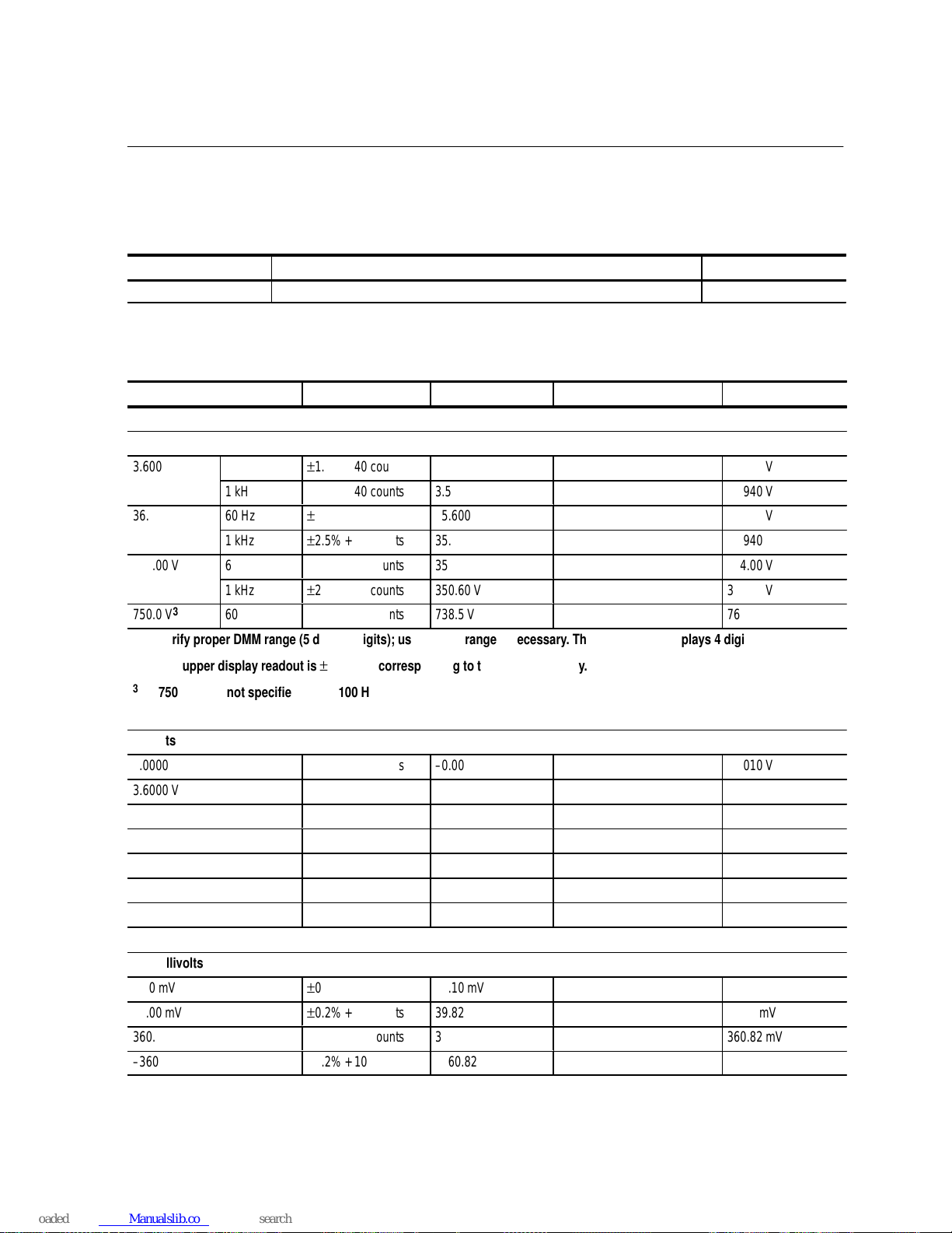
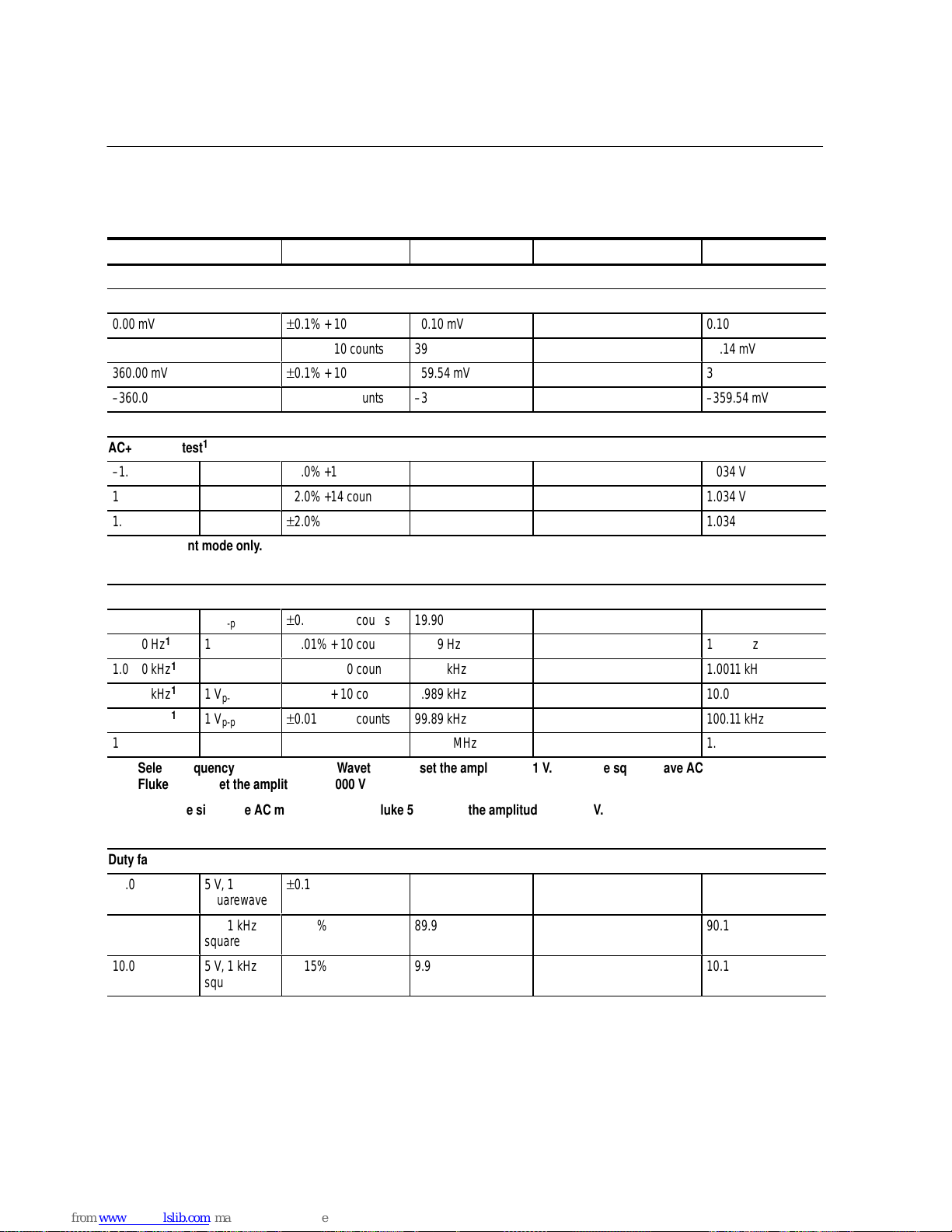
DMM830 Test Records
Serial number Procedure performed by Date
DMM830 test record
Test input Tolerance Display minimum Reading Display maximum
AC volts test
1,2
�����
3.6000 V
���
60 Hz
������
±
1.0% + 40 counts
������
3.5600 V
��������
�����
3.6400 V
�����
���
1 kHz
������
±
2.5% + 40 counts
������
3.5060 V
��������
�����
3.6940 V
�����
36.000 V
���
60 Hz
������
±
1.0% + 40 counts
������
35.600 V
��������
�����
36.400 V
�����
���
1 kHz
������
±
2.5% + 40 counts
������
35.060 V
��������
�����
36.940 V
�����
����
�
360.00 V
���
��
�
60 Hz
������
�����
�
±
1.0% + 40 counts
������
�����
�
356.00 V
��������
�������
�
�����
����
�
364.00 V
�����
���
1 kHz
������
±
2.5% + 40 counts
������
350.60 V
��������
�����
369.40 V
�����
750.0 V
3
���
60 Hz
������
±
1.0% + 40 counts
������
738.5 V
��������
�����
761.5 V
1
Verify proper DMM range (5 display digits); use manual range if necessary. The 750 V range displays 4 digits.
2
The upper display readout is ±2 counts corresponding to the input frequency.
3
750 V range not specified above 100 Hz.
DC volts test
��������
0.0000 V
������
±
0.2% + 10 counts
������
– 0.0010 V
��������
�����
0.0010 V
��������
3.6000 V
������
±
0.2% + 10 counts
������
3.5918 V
��������
�����
3.6082 V
��������
– 3.6000 V
������
±
0.2% + 10 counts
������
– 3.6082 V
��������
�����
– 3.5918 V
��������
36.000 V
������
±
0.2% + 10 counts
������
35.918 V
��������
�����
36.082 V
��������
360.00 V
������
±
0.2% + 10 counts
������
359.18 V
��������
�����
360.82 V
��������
1000.0 V
������
±
0.2% + 10 counts
������
997.0 V
��������
�����
1003.0 V
��������
– 1000.0 V
������
±
0.2% + 10 counts
������
– 1003.0 V
��������
�����
– 997.0 V
DC millivolts test
��������
0.00 mV
������
±
0.2% + 10 counts
������
– 0.10 mV
��������
�����
0.10 mV
��������
40.00 mV
������
±
0.2% + 10 counts
������
39.82 mV
��������
�����
40.18 mV
��������
360.00 mV
������
±
0.2% + 10 counts
������
359.18 mV
��������
�����
360.82 mV
��������
– 360.00 mV
������
±
0.2% + 10 counts
������
– 360.82 mV
��������
�����
– 359.18 mV
Page 20
DMM800 Series Performance Verification
20
Handheld Instruments Basic Service
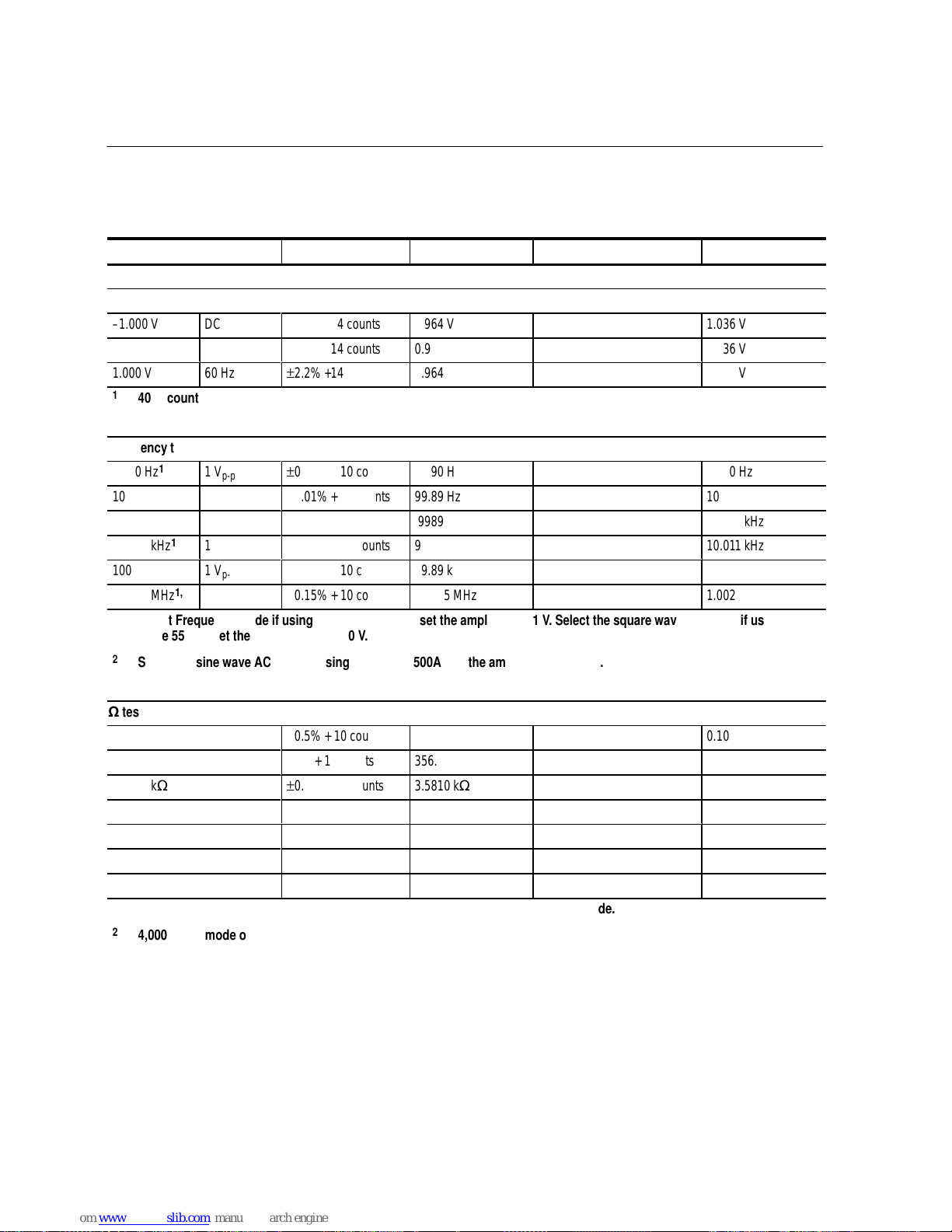
DMM830 test record (cont.)
Test input Display maximumReadingDisplay minimumTolerance
AC+DC volts test
1
���
�
– 1.000 V
����
���
�
DC
����
�
±
2.2% +14 counts
������
�����
�
0.964 V
��������
�������
�
�����
����
�
1.036 V
1.000 V
����
DC
±
2.2% +14 counts
������
0.964 V
��������
�����
1.036 V
1.000 V
����
60 Hz
±
2.2% +14 counts
������
0.964 V
��������
�����
1.036 V
1
4000 count mode only.
Frequency test
20.00 H z
1
����
1 V
p-p
±
0.01% + 10 counts
������
19.90 H z
��������
�����
20.10 H z
100.00 Hz
1
����
1 V
p-p
±
0.01% + 10 counts
������
99.89 H z
��������
�����
100.11 Hz
���
�
1.0000 kHz
1
����
���
�
1 V
p-p
����
�
±
0.01% + 10 counts
������
�����
�
.9989 kH z
��������
�������
�
�����
����
�
1.0011 kHz
10.000 kHz
1
����
1 V
p-p
±
0.01% + 10 counts
������
9.989 kH z
��������
�����
10.011 kHz
100.00 kHz
1
����
1 V
p-p
±
0.01% + 10 counts
������
99.89 kH z
��������
�����
100.11 kHz
1.0000 MH z
1,2
����
1 V
p-p
±
0.15% + 10 counts
������
0.9975 MH z
��������
�����
1.0025 MH z
1
Select Frequency mode if using the Wavetek 9100; set the amplitude to 1 V. Select the square wave AC mode if using the
Fluke 5500A; set the amplitude to 1.000 V.
2
Select the sine wave AC mode if using the Fluke 5500A; set the amplitude to 0.354 V.
test
0.00
1
±
0.5% + 10 counts
������
– 0.10
��������
�����
0.10
�������
�
360.00
1
����
�
±
1% + 10 counts
������
�����
�
356.30
��������
�������
�
�����
����
�
363.70
3.6000 k
±
0.5% + 10 counts
������
3.5810 k
��������
�����
3.6190 k
36.000 k
±
0.5% + 10 counts
������
35.810 k
��������
�����
36.190 k
360.00 k
±
0.5% + 10 counts
������
358.10 k
��������
�����
361.90 k
3.6000 M
±
1% + 10 counts
������
3.5630 M
��������
�����
3.6370 M
20.00 M
2
±
5% + 10 counts
������
18.90 M
��������
�����
21.10 M
1
To test these values with the Fluke 5500A, apply 0.0 and set the DMM to Delta mode.
2
4,000 count mode only.
Page 21
DMM800 Series Performance Verification
Handheld Instruments Basic Service
21
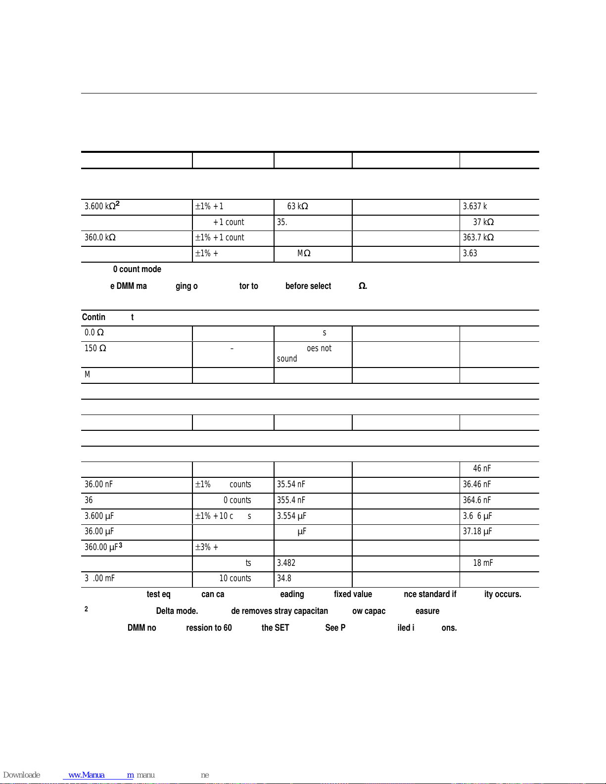
DMM830 test record (cont.)
Test input Display maximumReadingDisplay minimumTolerance
Low voltage test
1
��������
�������
�
3.600 k
������
�����
�
±
1% + 1 count
������
�����
�
3.563 k
��������
�������
�
�����
����
�
3.637 k
��������
36.00 k
������
±
1% + 1 count
������
35.63 k
��������
�����
36.37 k
��������
360.0 k
������
±
1% + 1 count
������
356.3 k
��������
�����
363.7 k
��������
3.600 M
������
±
1% + 1 count
������
3.563 M
��������
�����
3.637 M
1
4000 count mode only.
2
Use DMM manual ranging or set calibrator to 3.0 k before selecting 3.6k.
Continuity test
��������
�������
�
0.0
������
�����
�
–
������
�����
�
Beeper sounds
��������
�������
�
�����
����
�
��������
�������
�
150
������
�����
�
–
������
�����
�
Beeper does not
sound
��������
�������
�
�����
����
�
Multimeter leads shorted – Beeper sounds
Diode test
��������
0.5 V
������
������
0.400 V
��������
�����
0.600 V
Capacitance test
1,2
��������
3.600 nF
������
±
1% + 10 counts
������
3.554 nF
��������
�����
3.646 nF
��������
�������
�
36.00 nF
������
�����
�
±
1% + 10 counts
������
�����
�
35.54 nF
��������
�������
�
�����
����
�
36.46 nF
��������
360.0 nF
������
±
1% + 10 counts
������
355.4 nF
��������
�����
364.6 nF
��������
3.600
F
������
±
1% + 10 counts
������
3.554
F
��������
�����
3.646 F
��������
36.00 F
������
±
3% + 10 counts
������
34.82 F
��������
�����
37.18 F
��������
360.00 F
3
������
±
3% + 10 counts
������
348.2 F
��������
�����
371.8 F
��������
3.600 mF
3
������
±
3% + 10 counts
������
3.482 mF
��������
�����
3.718 mF
��������
36.00 mF
3
������
±
3% + 10 counts
������
34.82 mF
��������
�����
37.18 mF
1
Variations in test equipment can cause erroneous readings. Use a fixed value capacitance standard if instability occurs.
2
Set the DMM to Delta mode. Delta mode removes stray capacitance for low capacitance measurements.
3
Set the DMM noise suppression to 60 Hz with the SETUP mode. See Page 15 for detailed instructions.
Page 22
DMM800 Series Performance Verification
22
Handheld Instruments Basic Service
DMM830 test record (cont.)
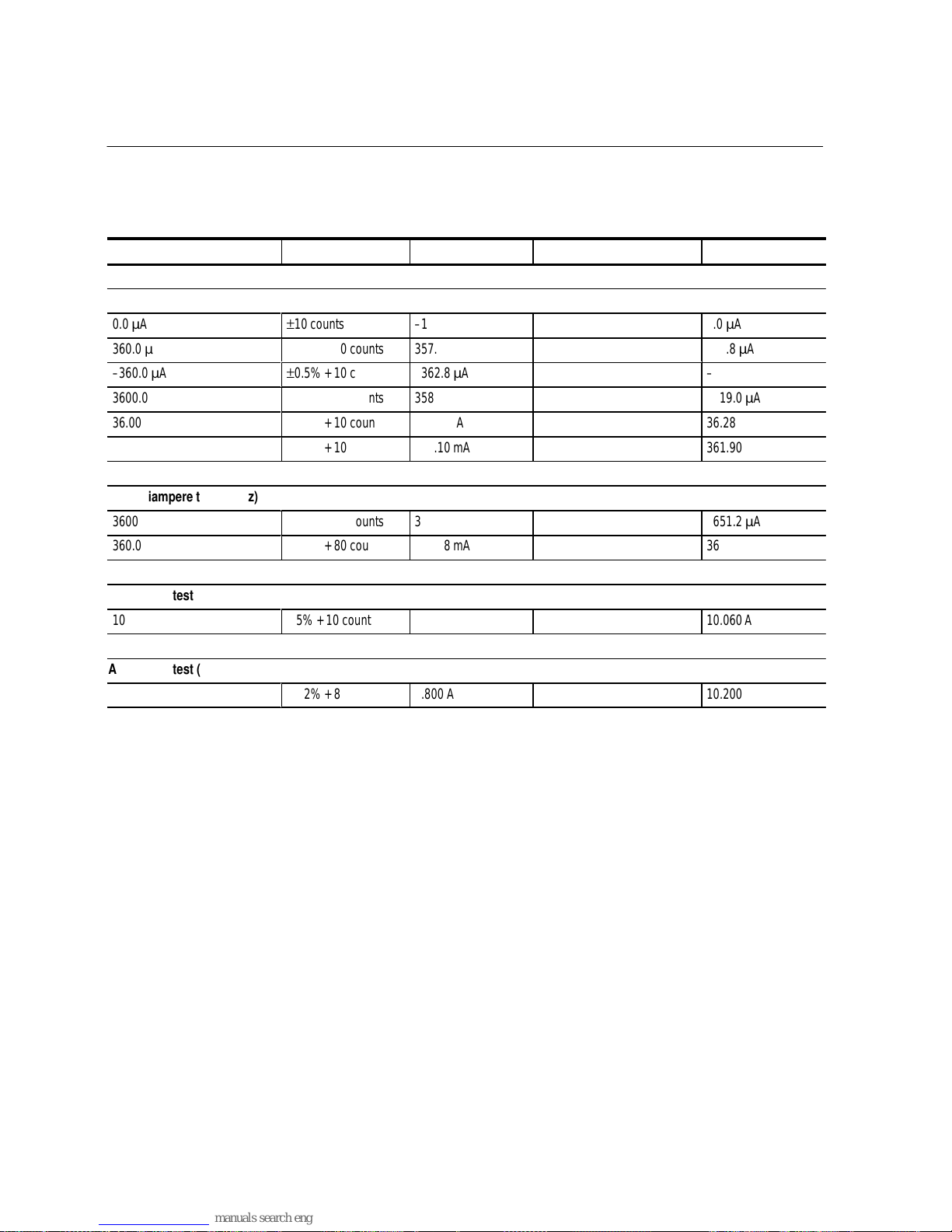
Test input Display maximumReadingDisplay minimumTolerance
DC milliampere test
�������
�
0.0 A
����
�
±
10 counts
������
�����
�
– 1.0 A
��������
�������
�
�����
����
�
1.0 A
360.0 A
±
0.5% + 10 counts
������
357.2 A
��������
�����
362.8 A
– 360.0
A
±
0.5% + 10 counts
������
– 362.8
A
��������
�����
– 357.2 A
3600.0 A
±
0.5% + 10 counts
������
3581.0 A
��������
�����
3619.0 A
36.00 mA
±
0.5% + 10 counts
������
35.72 mA
��������
�����
36.28 mA
360.00 mA
±
0.5% + 10 counts
������
358.10 mA
��������
�����
361.90 mA
AC milliampere test (60 Hz)
�������
�
3600.0 A
����
�
±
1.2% + 80 counts
������
�����
�
3548.8 A
��������
�������
�
�����
����
�
3651.2 A
360.00 mA
±
1.2% + 80 counts
������
354.88 mA
��������
�����
365.12 mA
DC ampere test
10.000 A
0.5% + 10 counts
������
9.940 A
��������
�����
10.060 A
AC ampere test (60 Hz)
10.000 A
±
1.2% + 80 counts
������
9.800 A
��������
�����
10.200 A
Page 23

DMM800 Series Performance Verification
Handheld Instruments Basic Service
23
DMM850 Test Records
Serial number Procedure performed by Date
DMM850 test record
Test input Tolerance Display minimum Reading Display maximum
AC volts test
1,2
�����
3.6000 V
���
60 Hz
������
±
0.8% + 40 counts
������
3.5672 V
��������
�����
3.6328 V
�����
���
500 H z
������
±
2.0% + 40 counts
������
3.5240 V
��������
�����
3.6760 V
�����
���
10 kHz
������
±
3.5% + 40 counts
������
3.4700 V
��������
�����
3.7300 V
�����
36.000 V
���
500 H z
������
±
2.0% + 40 counts
������
35.240 V
��������
�����
36.760 V
�����
����
�
���
��
�
10 kHz
������
�����
�
±
3.5% + 40 counts
������
�����
�
34.700 V
��������
�������
�
�����
����
�
37.300 V
�����
360.00 V
���
500 H z
������
±
2.0% + 40 counts
������
352.40 V
��������
�����
367.60 V
�����
���
10 kHz
������
±
3.5% + 40 counts
������
347.00 V
��������
�����
373.00 V
�����
750.0 V
3
���
60 Hz
������
±
0.8% + 40 counts
������
740.0 V
��������
�����
760.0 V
1
Verify the proper DMM range (5 display digits); use the manual range if necessary. The 750 V range displays 4 digits.
2
The upper display readout is ±2 counts corresponding to the input frequency.
3
750 V range not specified above 100 Hz.
DC volts test
��������
0.0000 V
������
±
0.1% + 10 counts
������
– 0.0010 V
��������
�����
0.0010 V
��������
3.6000 V
������
±
0.1% + 10 counts
������
3.5954 V
��������
�����
3.6046 V
��������
– 3.6000 V
������
±
0.1% + 10 counts
������
– 3.6046 V
��������
�����
– 3.5954 V
��������
36.000 V
������
±
0.1% + 10 counts
������
35.954 V
��������
�����
36.046 V
��������
360.00 V
������
±
0.1% + 10 counts
������
359.54 V
��������
�����
360.46 V
��������
1000.0 V
������
±
0.1% + 10 counts
������
998.0 V
��������
�����
1002.0 V
��������
�������
�
– 1000.0 V
������
�����
�
±
0.1% + 10 counts
������
�����
�
– 1002.0 V
��������
�������
�
�����
����
�
– 998.0 V
Page 24
DMM800 Series Performance Verification
24
Handheld Instruments Basic Service
DMM850 test record (cont.)
Test input Display maximumReadingDisplay minimumTolerance
DC millivolts test
�������
�
0.00 mV
����
�
±
0.1% + 10 counts
������
�����
�
– 0.10 mV
��������
�������
�
�����
����
�
0.10 mV
40.00 mV
±
0.1% + 10 counts
������
39.86 mV
��������
�����
40.14 mV
360.00 mV
±
0.1% + 10 counts
������
359.54 mV
��������
�����
360.46 mV
– 360.00 mV
±
0.1% + 10 counts
������
– 360.46 mV
��������
�����
– 359.54 mV
AC+DC volts test
1
– 1.000 V
����
DC
±
2.0% +14 counts
������
0.966 V
��������
�����
1.034 V
1.000 V
����
DC
±
2.0% +14 counts
������
0.966 V
��������
�����
1.034 V
���
�
1.000 V
����
���
�
60 Hz
����
�
±
2.0% +14 counts
������
�����
�
0.966 V
��������
�������
�
�����
����
�
1.034 V
1
4000 count mode only.
Frequency test
20.00 H z
1
����
1 V
p-p
±
0.01% + 10 counts
������
19.90 H z
��������
�����
20.10 H z
100.00 Hz
1
����
1 V
p-p
±
0.01% + 10 counts
������
99.89 H z
��������
�����
100.11 Hz
1.0000 kHz
1
����
1 V
p-p
±
0.01% + 10 counts
������
.9989 kH z
��������
�����
1.0011 kHz
10.000 kHz
1
����
1 V
p-p
±
0.01% + 10 counts
������
9.989 kH z
��������
�����
10.011 kHz
���
�
100.00 kHz
1
����
���
�
1 V
p-p
����
�
±
0.01% + 10 counts
������
�����
�
99.89 kH z
��������
�������
�
�����
����
�
100.11 kHz
1.0000 MH z
1,2
����
1 V
p-p
±
0.15% + 10 counts
������
0.9975 MH z
��������
�����
1.0025 MH z
1
Select Frequency mode if using the Wavetek 9100; set the amplitude to 1 V. Select the square wave AC mode if using the
Fluke 5500A; set the amplitude to 1.000 V.
2
Select the sine wave AC mode if using the Fluke 5500A; set the amplitude to 0.354 V.
Duty factor test
���
�
50.0
����
���
�
5 V, 1 kHz
squarewave
����
�
±
0.15%
������
�����
�
49.9
��������
�������
�
�����
����
�
50.1
���
�
90.0
����
���
�
5 V, 1 kHz
squarewave
����
�
±
0.15%
������
�����
�
89.9
��������
�������
�
�����
����
�
90.1
���
�
10.0
����
���
�
5 V, 1 kHz
squarewave
����
�
±
0.15%
������
�����
�
9.9
��������
�������
�
�����
����
�
10.1
Page 25
DMM800 Series Performance Verification
Handheld Instruments Basic Service
25
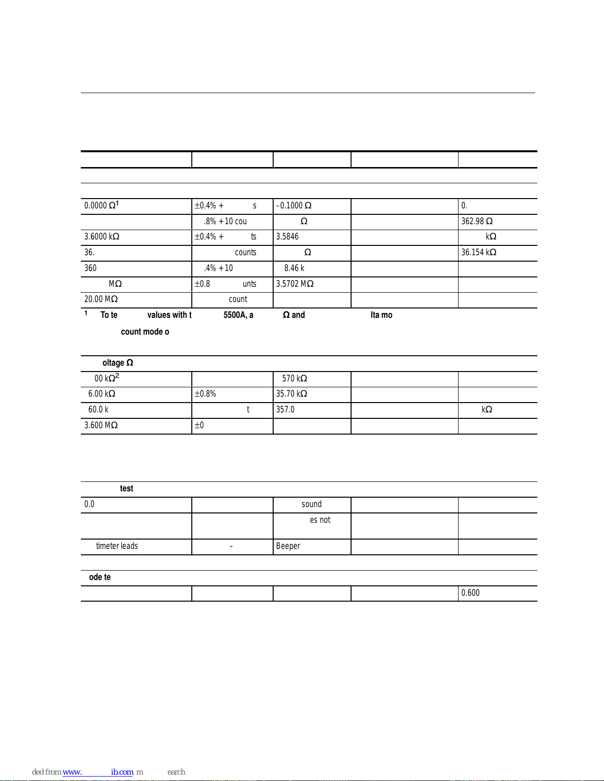
DMM850 test record (cont.)
Test input Display maximumReadingDisplay minimumTolerance
test
��������
�������
�
0.0000
1
������
�����
�
±
0.4% + 10 counts
������
�����
�
– 0.1000
��������
�������
�
�����
����
�
0.1000
��������
360.00
1
������
±
0.8% + 10 counts
������
357.02
��������
�����
362.98
��������
3.6000 k
������
±
0.4% + 10 counts
������
3.5846 k
��������
�����
3.6154 k
��������
36.000 k
������
±
0.4% + 10 counts
������
35.846 k
��������
�����
36.154 k
��������
360.00 k
������
±
0.4% + 10 counts
������
358.46 k
��������
�����
361.54 k
��������
3.6000 M
������
±
0.8% + 10 counts
������
3.5702 M
��������
�����
3.6298 M
��������
20.00 M
2
������
±
5% + 10 counts
������
18.90 M
��������
�����
21.10 M
1
To test these values with the Fluke 5500A, apply 0.0 and set the DMM to Delta mode.
2
4,000 count mode only.
Low voltage test
1
��������
3.600 k
������
±
0.8% + 1 count
������
3.570 k
��������
�����
3.630 k
��������
36.00 k
������
±
0.8% + 1 count
������
35.70 k
��������
�����
36.30 k
��������
360.0 k
������
±
0.8% + 1 count
������
357.0 k
��������
�����
363.0 k
��������
3.600 M
������
±
0.8% + 1 count
������
3.570 M
��������
�����
3.630 M
1
4000 count mode only.
2
Use DMM manual ranging or set calibrator to 3.0 k before selecting 3.6k.
Continuity test
��������
0.0
������
–
������
Beeper sounds
��������
�����
��������
�������
�
150
������
�����
�
–
������
�����
�
Beeper does not
sound
��������
�������
�
�����
����
�
Multimeter leads shorted – Beeper sounds
Diode test
��������
�������
�
0.5 V
������
�����
�
–
������
�����
�
0.400 V
��������
�������
�
�����
����
�
0.600 V
Page 26

DMM800 Series Performance Verification
26
Handheld Instruments Basic Service
DMM850 test record (cont.)
Test input Display maximumReadingDisplay minimumTolerance
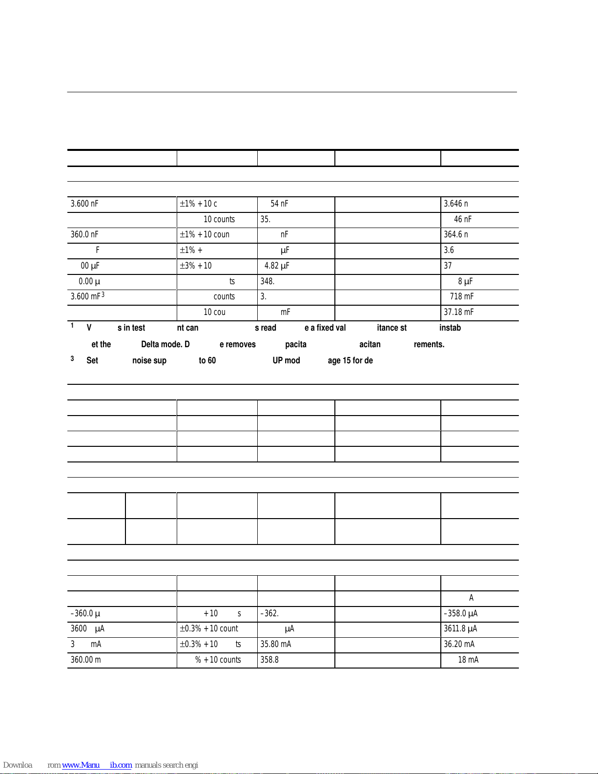
Capacitance test
1,2
�������
�
3.600 nF
����
�
±
1% + 10 counts
������
�����
�
3.554 nF
��������
�������
�
�����
����
�
3.646 nF
36.00 nF
±
1% + 10 counts
������
35.54 nF
��������
�����
36.46 nF
360.0 nF
±
1% + 10 counts
������
355.4 nF
��������
�����
364.6 nF
3.600 F
±
1% + 10 counts
������
3.554 F
��������
�����
3.646 F
36.00 F
±
3% + 10 counts
������
34.82 F
��������
�����
37.18 F
360.00 F
3
±
3% + 10 counts
������
348.2 F
��������
�����
371.8 F
3.600 mF
3
±
3% + 10 counts
������
3.482 mF
��������
�����
3.718 mF
36.00 mF
3
±
3% + 10 counts
������
34.82 mF
��������
�����
37.18 mF
1
Variations in test equipment can cause erroneous readings. Use a fixed value capacitance standard if instability occurs.
2
Set the DMM to Delta mode. Delta mode removes stray capacitance for low capacitance measurements.
3
Set the DMM noise suppression to 60 Hz with the SETUP mode. See Page 15 for detailed instructions.
Temperature test
0.0 C
±2
C
������
– 2.0
��������
�����
2.0
– 40.0 C
±2
C
������
– 42.0
��������
�����
– 38.0
�������
�
100.0 C
����
�
±2
C
������
�����
�
98.0
��������
�������
�
�����
����
�
102.0
950.0 C
±2
C
������
948.0
��������
�����
952.0
DC milliampere test
0.0 A
±
10 counts
������
– 1.0 A
��������
�����
1.0 A
360.0 A
±
0.4% + 10 counts
������
357.6 A
��������
�����
362.4 A
– 360.0 A
±
0.4% + 10 counts
������
– 362.4 A
��������
�����
– 357.6 A
3600.0 A
±
0.4% + 10 counts
������
3584.6 A
��������
�����
3615.4 A
�������
�
36.00 mA
����
�
±
0.4% + 10 counts
������
�����
�
35.76 mA
��������
�������
�
�����
����
�
36.24 mA
360.00 mA
±
0.4% + 10 counts
������
358.46 mA
��������
�����
361.54 mA
Page 27
DMM800 Series Performance Verification
Handheld Instruments Basic Service
27
DMM850 test record (cont.)
Test input Display maximumReadingDisplay minimumTolerance
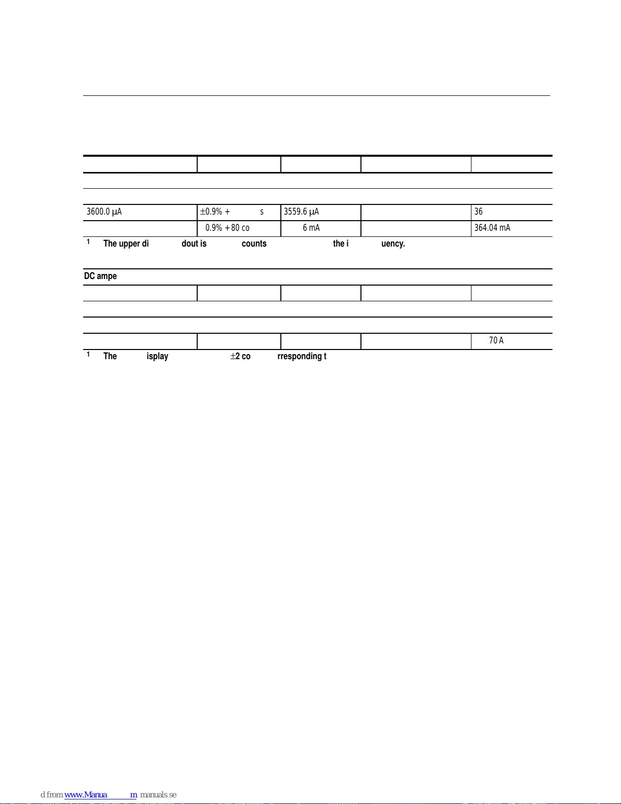
AC milliampere test (60 Hz)
1
��������
�������
�
3600.0 A
������
�����
�
±
0.9% + 80 counts
������
�����
�
3559.6 A
��������
�������
�
�����
����
�
3640.4 A
��������
360.00 mA
������
±
0.9% + 80 counts
������
355.96 mA
��������
�����
364.04 mA
1
The upper display readout is 60 Hz ±2 counts corresponding to the input frequency.
DC ampere test
��������
10.000 A
������
±
0.4% + 10 counts
������
9.950 A
��������
�����
10.050 A
AC ampere test (60 Hz)
1
��������
�������
�
10.000 A
������
�����
�
±
0.9% + 80 counts
������
�����
�
9.830 A
��������
�������
�
�����
����
�
10.170 A
1
The upper display readout is 60 Hz ±2 counts corresponding to the input frequency.
Page 28

DMM800 Series Performance Verification
28
Handheld Instruments Basic Service
Page 29

DMM800 Series Performance Verification
Handheld Instruments Basic Service
29
DMM870 Test Records
Serial number Procedure performed by Date
DMM870 test record
Test input Tolerance Display minimum Reading Display maximum
AC volts test
1,2
�����
3.6000 V
���
60 Hz
������
±
0.7% + 40 counts
������
3.5708 V
��������
�����
3.6292 V
�����
���
500 H z
������
±
1.5% + 40 counts
������
3.5420 V
��������
�����
3.6580 V
�����
���
10 kHz
������
±
2.5% + 40 counts
������
3.5060 V
��������
�����
3.6940 V
�����
36.000 V
���
500 H z
������
±
1.5% + 40 counts
������
35.420 V
��������
�����
36.580 V
�����
����
�
���
��
�
10 kHz
������
�����
�
±
2.5% + 40 counts
������
�����
�
35.060 V
��������
�������
�
�����
����
�
36.940 V
�����
360.00 V
���
500 H z
������
±
1.5% + 40 counts
������
354.20 V
��������
�����
365.80 V
�����
���
10 kHz
������
±
2.5% + 40 counts
������
350.60 V
��������
�����
369.40 V
�����
750.0 V
3
���
60 Hz
������
±
0.7% + 40 counts
������
740.7 V
��������
�����
759.3V
1
Verify the proper DMM range (5 display digits); use the manual range if necessary. The 750 V range displays 4 digits.
2
The upper display readout is ±2 counts corresponding to the input frequency.
3
750 V range not specified above 100 Hz.
DC volts test
��������
0.0000 V
������
±
0.06% + 10 counts
������
– 0.0010 V
��������
�����
0.0010 V
��������
3.6000 V
������
±
0.06% + 10 counts
������
3.5969 V
��������
�����
3.6031 V
��������
– 3.6000 V
������
±
0.06% + 10 counts
������
– 3.6031 V
��������
�����
– 3.5969 V
��������
36.000 V
������
±
0.06% + 10 counts
������
35.969 V
��������
�����
36.031 V
��������
360.00 V
������
±
0.06% + 10 counts
������
359.69 V
��������
�����
360.31 V
��������
1000.0 V
������
±
0.06% + 10 counts
������
998.4 V
��������
�����
1001.6 V
��������
�������
�
– 1000.0 V
������
�����
�
±
0.06% + 10 counts
������
�����
�
– 1001.6 V
��������
�������
�
�����
����
�
– 998.4 V
Page 30

DMM800 Series Performance Verification
30
Handheld Instruments Basic Service
DMM870 test record (cont.)
Test input Display maximumReadingDisplay minimumTolerance
DC millivolts test
�������
�
0.00 mV
����
�
±
0.06% + 10 counts
������
�����
�
– 0.10 mV
��������
�������
�
�����
����
�
0.10 mV
40.00 mV
±
0.06% + 10 counts
������
39.88 mV
��������
�����
40.12 mV
360.00 mV
±
0.06% + 10 counts
������
359.69 mV
��������
�����
360.31 mV
– 360.00 mV
±
0.06% + 10 counts
������
– 360.31 mV
��������
�����
– 359.69 mV
AC+DC volts test
1
– 1.000 V
����
DC
±
1.9% +14 counts
������
0.967 V
��������
�����
1.033 V
1.000 V
����
DC
±
1.9% +14 counts
������
0.967 V
��������
�����
1.033 V
���
�
1.000 V
����
���
�
60 Hz
����
�
±
1.9% +14 counts
������
�����
�
0.967 V
��������
�������
�
�����
����
�
1.033 V
1
4000 count mode only.
Frequency test
20.00 H z
1
����
1 V
p-p
±
0.01% + 10 counts
������
19.90 H z
��������
�����
20.10 H z
100.00 Hz
1
����
1 V
p-p
±
0.01% + 10 counts
������
99.89 H z
��������
�����
100.11 Hz
1.0000 kHz
1
����
1 V
p-p
±
0.01% + 10 counts
������
.9989 kH z
��������
�����
1.0011 kHz
10.000 kHz
1
����
1 V
p-p
±
0.01% + 10 counts
������
9.989 kH z
��������
�����
10.011 kHz
���
�
100.00 kHz
1
����
���
�
1 V
p-p
����
�
±
0.01% + 10 counts
������
�����
�
99.89 kH z
��������
�������
�
�����
����
�
100.11 kHz
1.0000 MH z
1,2
����
1 V
p-p
±
0.15% + 10 counts
������
0.9975 MH z
��������
�����
1.0025 MH z
1
Select Frequency mode if using the Wavetek 9100; set the amplitude to 1 V. Select the square wave AC mode if using the
Fluke 5500A; set the amplitude to 1.000 V.
2
Select the sine wave AC mode if using the Fluke 5500A; set the amplitude to 0.354 V.
Duty factor test
���
�
50.0
����
���
�
5 V, 1 kHz
squarewave
����
�
±
0.15%
������
�����
�
49.9
��������
�������
�
�����
����
�
50.1
���
�
90.0
����
���
�
5 V, 1 kHz
squarewave
����
�
±
0.15%
������
�����
�
89.9
��������
�������
�
�����
����
�
90.1
���
�
10.0
����
���
�
5 V, 1 kHz
squarewave
����
�
±
0.15%
������
�����
�
9.9
��������
�������
�
�����
����
�
10.1
Page 31

DMM800 Series Performance Verification
Handheld Instruments Basic Service
31
DMM870 test record (cont.)
Test input Display maximumReadingDisplay minimumTolerance
test
��������
�������
�
0.0000
1
������
�����
�
±
0.3% + 10 counts
������
�����
�
– 0.1000
��������
�������
�
�����
����
�
0.1000
��������
360.00
1
������
±
0.6% + 10 counts
������
357.74
��������
�����
362.26
��������
3.6000 k
������
±
0.3% + 10 counts
������
3.5882 k
��������
�����
3.6118 k
��������
36.000 k
������
±
0.3% + 10 counts
������
35.882 k
��������
�����
36.118 k
��������
360.00 k
������
±
0.3% + 10 counts
������
358.82 k
��������
�����
361.18 k
��������
3.6000 M
������
±
0.6% + 10 counts
������
3.5774 M
��������
�����
3.6226 M
��������
20.00 M
2
������
±
5% + 10 counts
������
18.90 M
��������
�����
21.10 M
1
To test these values with the Fluke 5500A, apply 0.0 and set the DMM to Delta mode.
2
Verify the DMM is in the 4,000 count mode for this test.
Low voltage test
1
��������
3.600 k
������
±
0.6% + 1 count
������
3.577 k
��������
�����
3.623 k
��������
36.00 k
������
±
0.6% + 1 count
������
35.77 k
��������
�����
36.23 k
��������
360.0 k
������
±
0.6% + 1 count
������
357.7 k
��������
�����
362.3 k
��������
3.600 M
������
±
0.6% + 1 count
������
3.577 M
��������
�����
3.623 M
1
4000 count mode only.
2
Use DMM manual ranging or set calibrator to 3.0 k before selecting 3.6k.
Continuity test
��������
0.0
������
–
������
Beeper sounds
��������
�����
��������
�������
�
150
������
�����
�
–
������
�����
�
Beeper does not
sound
��������
�������
�
�����
����
�
Multimeter leads shorted – Beeper sounds
Diode test
��������
�������
�
0.5 V
������
�����
�
–
������
�����
�
0.400 V
��������
�������
�
�����
����
�
0.600 V
Page 32
DMM800 Series Performance Verification
32
Handheld Instruments Basic Service
DMM870 test record (cont.)
Test input Display maximumReadingDisplay minimumTolerance
Capacitance test
1,2
�������
�
3.600 nF
����
�
±
1% + 10 counts
������
�����
�
3.554 nF
��������
�������
�
�����
����
�
3.646 nF
36.00 nF
±
1% + 10 counts
������
35.54 nF
��������
�����
36.46 nF
360.0 nF
±
1% + 10 counts
������
355.4 nF
��������
�����
364.6 nF
3.600 F
±
1% + 10 counts
������
3.554 F
��������
�����
3.646 F
36.00 F
±
3% + 10 counts
������
34.82 F
��������
�����
37.18 F
360.00 F
3
±
3% + 10 counts
������
348.2 F
��������
�����
371.8 F
3.600 mF
3
±
3% + 10 counts
������
3.482 mF
��������
�����
3.718 mF
36.00 mF
3
±
3% + 10 counts
������
34.82 mF
��������
�����
37.18 mF
1
Variations in test equipment can cause erroneous readings. Use a fixed value capacitance standard if instability occurs.
2
Set the DMM to Delta mode. Delta mode removes stray capacitance for low capacitance measurements.
3
Set the DMM noise suppression to 60 Hz with the SETUP mode. See Page 15 for detailed instructions.
Temperature test
0.0 C
±2
C
������
– 2.0
��������
�����
2.0
– 40.0 C
±2
C
������
– 42.0
��������
�����
– 38.0
�������
�
100.0 C
����
�
±2
C
������
�����
�
98.0
��������
�������
�
�����
����
�
102.0
950.0 C
±2
C
������
948.0
��������
�����
952.0
Volts peak hold test
���
�
1 V
R MS
(60 Hz,
1.414 V
p
)
����
���
�
MAX
����
�
±
5% + 40 counts
������
�����
�
1.303 V
��������
�������
�
�����
����
�
1.524 V
���
�
1 V
R MS
(60 Hz,
1.414 Vp)
����
���
�
MIN
����
�
±
5% + 40 counts
������
�����
�
– 1.524 V
��������
�������
�
�����
����
�
– 1.303 V
DC milliampere test
0.0 A
±
10 counts
������
– 1.0 A
��������
�����
1.0 A
360.0 A
±
0.3% + 10 counts
������
358.0 A
��������
�����
362.0 A
– 360.0 A
±
0.3% + 10 counts
������
– 362.0 A
��������
�����
– 358.0 A
�������
�
3600.0 A
����
�
±
0.3% + 10 counts
������
�����
�
3588.2 A
��������
�������
�
�����
����
�
3611.8 A
36.00 mA
±
0.3% + 10 counts
������
35.80 mA
��������
�����
36.20 mA
360.00 mA
±
0.3% + 10 counts
������
358.82 mA
��������
�����
361.18 mA
Page 33

DMM800 Series Performance Verification
Handheld Instruments Basic Service
33
DMM870 test record (cont.)
Test input Display maximumReadingDisplay minimumTolerance
AC milliampere test (60 Hz)
1
��������
�������
�
3600.0 A
������
�����
�
±
0.9% + 80 counts
������
�����
�
3559.6 A
��������
�������
�
�����
����
�
3640.4 A
��������
360.00 mA
������
±
0.9% + 80 counts
������
355.96 mA
��������
�����
364.04 mA
1
The upper display readout is 60 Hz ±2 counts corresponding to the input frequency.
DC ampere test
��������
10.000 A
������
±
0.3% + 10 counts
������
9.960 A
��������
�����
10.040 A
AC ampere test (60 Hz)
1
��������
�������
�
10.000 A
������
�����
�
±
0.9% + 80 counts
������
�����
�
9.830 A
��������
�������
�
�����
����
�
10.170 A
1
The upper display readout is 60 Hz ±2 counts corresponding to the input frequency.
Page 34

DMM800 Series Performance Verification
34
Handheld Instruments Basic Service
Page 35

Handheld Instruments Basic Service
35
DMM800 Series Adjustment Procedures
This section contains procedures to adjust DMM830, DMM850, and DMM870
multimeters. Perform these procedures once a year or if the DMM800 Series
Performance Verification procedure indicates the need for calibration.
In this section you will find the following information:
A list of adjustments
A list of test equipment needed to make the adjustments
Instructions on how to prepare the instrument for adjustment
Step-by-step adjustment procedures
The procedures in this section do not verify performance. To confirm that your
multimeter meets factory specifications, perform the procedures in the DMM800
Series Performance Verification section.
List of Adjustments
Use the adjustments listed in Table 9 to return DMM800 Series multimeters to
factory calibration.
Table 9: DMM800 series adjustments
Adjustments P art 1
DC Volts
AC Volts
C apacitance
Temperature (DM M 850 and DMM870)
DC Milliamperes
DC Amperes
Adjustments P art 2
AC R es ponse
Page 36

DMM800 Series Adjustment Procedures
36
Handheld Instruments Basic Service
Test Equipment
The test equipment listed in Table 8 on page 10 is a complete list of equipment
needed for the adjustment procedures. These procedures assume that the test
equipment is operating within tolerance.
Alternative test equipment must meet or exceed the intended minimum requirements specified in Table 8. If you substitute equipment, you may need to modify
the procedures.
Preparation for Adjustment
The following guidelines apply to all DMM800 Series adjustments:
Perform all adjustments in a 21 to 25
C ambient environment with a
relative humidity of 75% or less.
Warm up the multimeter for at least 15 minutes.
Do not alter any setting without reading the entire adjustment procedure first.
Do not alter a setting unless a performance characteristic cannot be met at the
current setting.
Read the Safety Summary at the beginning of this manual.
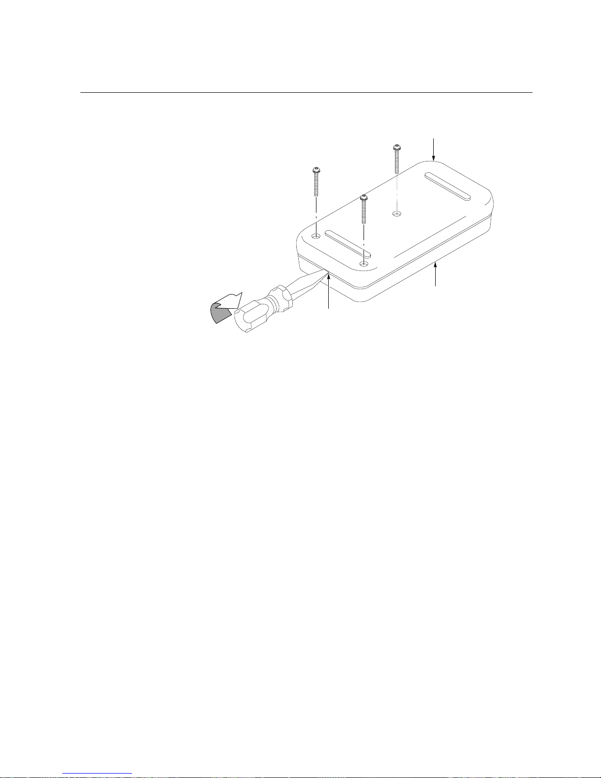
You must open the multimeter case to access the internal adjustments. Use the
following procedure to open the case.
1. Lay the meter face down on a flat work surface that cannot damage the
multimeter face.
2. Remove the three screws from the case bottom using a standard Philips-head
screwdriver.
3. Gently lift the end of the case bottom at the end opposite from the display.
Then lift the end nearest the display until it unsnaps from the case top. See
Figure 2 for details.
To reassemble the multimeter following the adjustments, see page 42.
Open the Meter Case
Page 37
DMM800 Series Adjustment Procedures
Handheld Instruments Basic Service
37
C as e top
C as e bottom
Twist
R emove screws (3)
Figure 2: Opening the meter case
Page 38

DMM800 Series Adjustment Procedures
38
Handheld Instruments Basic Service
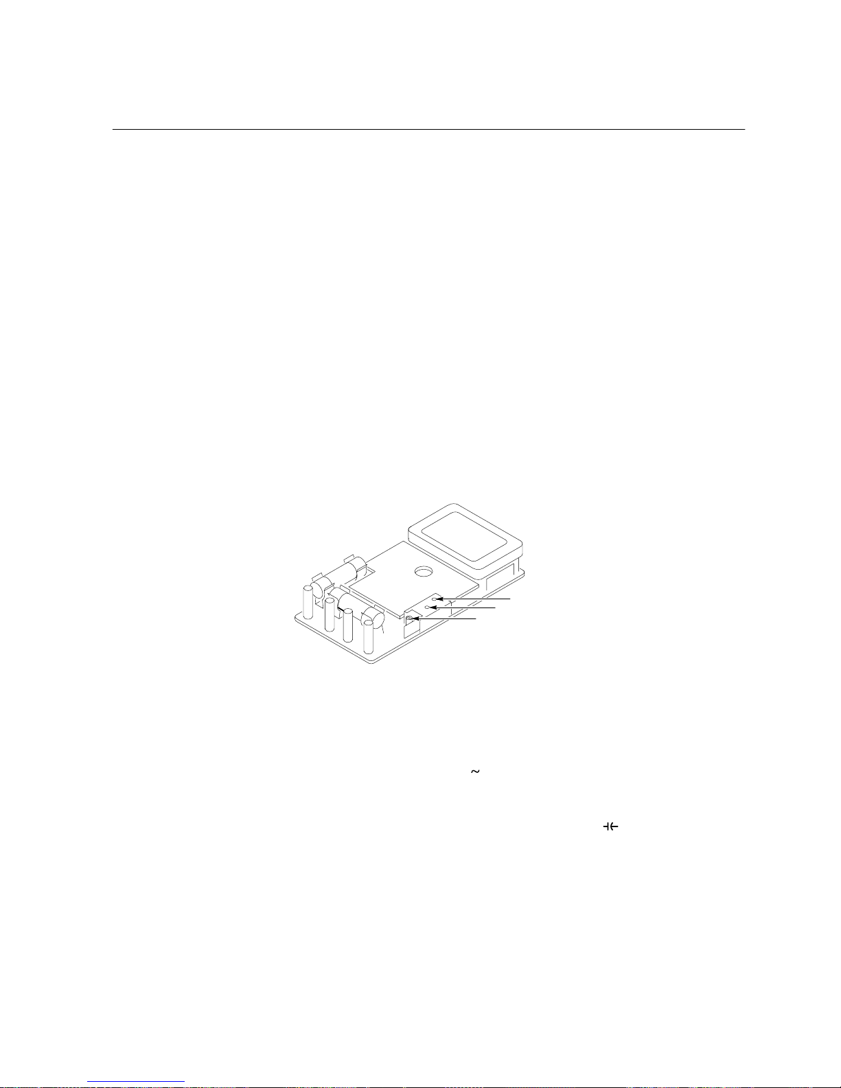
Adjustments Part 1
The procedures within this section use the adjustments accessible with the back
case removed from the multimeter.
VR 3
VR 2
VR 1
VR 6
VR 5
VR 4 (D M M850
and DM M 870)
Figure 3: Adjustment locations 1
Perform the following steps to adjust the DC voltage calibration.
1. Set the multimeter dial to V
.
2. Connect the outputs of the calibrator to the C V
and COM input
connectors of the multimeter.
3. Set the calibrator to output 3.0000 VDC.
4. Adjust VR5 until the display shows 2.9999 to 3.0001 VDC.
5. Turn the calibrator output off.
6. Disconnect the calibrator from the multimeter.
Perform the following steps to adjust the AC voltage calibration at 60 Hz.
1. Set the multimeter dial to V
.
2. Connect the outputs of the calibrator to the C V
and COM input
connectors of the multimeter.
3. Set the calibrator to output 2.0000 VAC at 60 Hz.
4. Adjust VR6 until the display shows 1.9999 to 2.0001 VAC.
DC Volts
AC Volts
Page 39

DMM800 Series Adjustment Procedures
Handheld Instruments Basic Service
39
5. Turn the calibrator output off.
6. Disconnect the calibrator from the multimeter.
Perform the following steps to adjust the capacitance calibration.
1. Set the multimeter dial to
.
2. Null the residual DMM and lead capacitance offset.
a. Using Fluke 5500A or Wavetek 9100 minus the 9105 front porch:
Turn the calibrator output off.
Connect the test leads to the multimeter C V
and COM
inputs.
Connect the multimeter COM lead to the calibrator common output.
Press the multimeter gold key followed by the /% key.
Connect the multimeter C V
lead to the remaining calibrator
output.
Turn the calibrator output on.
b. Using Wavetek 9100 with 9105 front porch:
Turn the calibrator output off.
Connect the multimeter test leads to the calibrator outputs.
Connect the calibrator common lead to the multimeter COM input.
Press the multimeter gold key followed by the /% key.
Connect the remaining calibrator output lead to the multimeter
C V
input.
Turn the calibrator output on.
3. Set the calibrator to output 300 nF.
4. Adjust VR2 until the display shows 299.9 to 300.1 nF.
5. Set the calibrator to output 1.000 �F.
6. Adjust VR3 until the display shows 0.999 to 1.001 �F.
7. Set the calibrator to output 100.0 �F.
8. Adjust VR1 until the display shows 99.9 to 100.1 �F.
9. Turn the calibrator output off.
Capacitance
Page 40

DMM800 Series Adjustment Procedures
40
Handheld Instruments Basic Service
10. Disconnect the calibrator from the multimeter.
Perform the following steps to adjust the temperature calibration.
1. Set the multimeter dial to C / F.
2. Connect the thermocouple adapter ATK01 to the C V
and COM input
connectors of the multimeter.
3. Set the calibrator to output 18.6 C.
4. Connect a K-type thermocouple from the calibrator output to the ATK01
thermocouple adapter.
5. Allow five minutes of settling time for a stable reading.
6. Adjust VR4 until the display shows 18.5 to 18.7 C.
7. Turn the calibrator output off.
8. Disconnect the calibrator from the multimeter.
Perform the following steps to adjust the DC milliamperes calibration.
1. Set the multimeter dial to mA
.
2. Connect the outputs of the calibrator to the �A mA and COM input connec-
tors of the multimeter.
3. Set calibrator to output 100.0 mA.
4. Press and hold the gold button for five seconds. (The multimeter beeps twice
when the gold button is first pressed and then two more beeps follow after
five seconds.)
5. Press the SETUP button and wait for the calibration to finish (CAL is
displayed during the calibration). After the calibration is completed, press
EXIT SETUP (blue button).
6. Turn the calibrator output off.
7. Disconnect the calibrator from the multimeter.
Perform the following steps to adjust the DC amperes calibration.
1. Set the multimeter dial to A
.
2. Connect the calibrator outputs to the multimeter A and COM inputs.
3. Set calibrator to output 10.00 A.
Temperature
(DMM850 and DMM870)
DC Milliamperes
DC Amperes
Page 41
DMM800 Series Adjustment Procedures
Handheld Instruments Basic Service
41
4. Press and hold the gold button for five seconds. (The multimeter beeps twice
when the gold button is first pressed and then two more beeps follow after
five seconds.)
5. Press the SETUP button and wait for the calibration to finish (CAL is
displayed during the calibration). After the calibration is completed, press
EXIT SETUP (blue button).
6. Turn the calibrator output off.
7. Disconnect the calibrator from the multimeter.
Adjustments Part 2
To perform the following procedure, you must lift out the entire circuit board
assembly from the top case half to access the adjustments. Perform this procedure only if the Performance Verification procedure indicates that the AC voltage
accuracy checks above 60 Hz is out of specification.
VC 3
VC 2
VC 1
Figure 4: Adjustment locations 2
Perform the following steps to adjust the AC voltage calibration above 60 Hz.
1. Set the multimeter dial to V
.
2. Lift the circuit board assembly out of the top case half.
3. Connect the outputs of the calibrator to the C V and COM input
connectors of the multimeter.
4. Set calibrator to output 100 VAC at 10 kHz (sinewave).
5. Adjust VC3 until the display shows +98.60 V.
6. Set the calibrator frequency to 500 Hz (sinewave).
AC Response
Page 42

DMM800 Series Adjustment Procedures
42
Handheld Instruments Basic Service
7. Confirm that the reading is less than 100.60 V. Repeat step 5 if necessary.
8. Set the calibrator frequency to 1 kHz (sinewave).
9. Confirm that the reading is less than 104.0 V. Repeat step 5 if necessary.
NOTE
. Steps 10 through 17 do not apply to the DMM830.
10. Set the calibrator to output 20 VAC at 10 kHz (sinewave).
11. Adjust VC1 until the display shows 19.700 V.
12. Set the calibrator frequency to 500 Hz (sinewave).
13. Confirm that the reading is less than 20.110 V. Repeat step 11 if necessary.
14. Set the calibrator to output 2 VAC at 10 kHz (sinewave).
15. Adjust VC2 until the display shows 1.9700 V.
16. Set the calibrator frequency to 500 Hz (sinewave).
17. Confirm that the reading is less than 2.011 V. Repeat step 15 if necessary.
18. Turn the calibrator output off.
19. Disconnect the calibrator from the multimeter.
Reassembling the Multimeter
1. Ensure that the rotary dial is properly aligned.
2. Align the tabs of the bottom case half with the slots in the top case half at the
end of the meter near the input connectors.
CAUTION.
Before closing the case, check that the rotary dial is properly aligned
and that the battery wires are not pinched.
3. Close the case, snapping the case halves together.
4. Reinstall the three screws.
 Loading...