

Page 1

Model 2308 Portable Device
Battery/Charger Simulator
Quick Start Guide
2308-903-01 Rev. A / July 2008
www.keithley.com
A GREATER MEASURE OF CONFIDENCE
Page 2

WARRANTY
Keithley Instruments, Inc. warrants this product to be free from defects in material and workmanship for a period of
one (1) year from date of shipment.
Keithley Instruments, Inc. warrants the following items for 90 days from the date of shipment: probes, cables,
software, rechargeable batteries, diskettes, and documentation.
During the warranty period, Keithley Instruments will, at its option, either repair or replace any product that proves
to be defective.
To exercise this warranty, write or call your local Keithley Instruments representative, or contact
Keithley Instruments headquarters in Cleveland, Ohio. You will be given prompt assistance and return instructions.
Send the product, transportation prepaid, to the indicated service facility. Repairs will be made and the product
returned, transportation prepaid. Repaired or replaced products are warranted for the balance of the original
warranty period, or at least 90 days.
LIMITATION OF WARRANTY
This warranty does not apply to defects resulting from product modification without Keithley Instruments’ express
written consent, or misuse of any product or part. This warranty also does not apply to fuses, software,
non-rechargeable batteries, damage from battery leakage, or problems arising from normal wear or failure to follow
instructions.
THIS WARRANTY IS IN LIEU OF ALL OTHER WARRANTIES, EXPRESSED OR IMPLIED, INCLUDING ANY
IMPLIED WARRANTY OF MERCHANTABILITY OR FITNESS FOR A PARTICULAR USE. THE REMEDIES
PROVIDED HEREIN ARE BUYER’S SOLE AND EXCLUSIVE REMEDIES.
NEITHER KEITHLEY INSTRUMENTS, INC. NOR ANY OF ITS EMPLOYEES SHALL BE LIABLE FOR ANY
DIRECT, INDIRECT, SPECIAL, INCIDENTAL, OR CONSEQUENTIAL DAMAGES ARISING OUT OF THE USE
OF ITS INSTRUMENTS AND SOFTWARE, EVEN IF KEITHLEY INSTRUMENTS, INC. HAS BEEN ADVISED IN
ADVANCE OF THE POSSIBILITY OF SUCH DAMAGES. SUCH EXCLUDED DAMAGES SHALL INCLUDE, BUT
ARE NOT LIMITED TO: COST OF REMOVAL AND INSTALLATION, LOSSES SUSTAINED AS THE RESULT OF
INJURY TO ANY PERSON, OR DAMAGE TO PROPERTY.
A G R E A T E R M E A S U R E O F C O N F I D E N C E
Keithley Instruments, Inc.
Corporate Headquarters • 28775 Aurora Road • Cleveland, Ohio 44139
440-248-0400 • Fax: 440-248-6168 • 1-888-KEITHLEY (1-888-534-8453) • www.keithley.com
3/07
Page 3

The following safety precautions should be observed before using this product and any associated instrumentation. Although some
instruments and accessories would normally be used with non-hazardous voltages, there are situations where hazardous conditions may
be present.
This product is intended for use by qualified personnel who recognize shock hazards and are familiar with the safety precautions required
to avoid possible injury. Read and follow all installation, operation, and maintenance information carefully before using the product. Refer
to the user documentation for complete product specifications.
If the product is used in a manner not specified, the protection provided by the product warranty may be impaired.
The types of product users are:
Responsible body is the individual or group responsible for the use and maintenance of equipment, for ensuring that the equipment is
operated within its specifications and operating limits, and for ensuring that operators are adequately trained.
Operators use the product for its intended function. They must be trained in electrical safety procedures and proper use of the instrument.
They must be protected from electric shock and contact with hazardous live circuits.
Maintenance personnel perform routine procedures on the product to keep it operating properly, for example, setting the line voltage or
replacing consumable materials. Maintenance procedures are described in the user documentation. The procedures explicitly state if the
operator may perform them. Otherwise, they should be performed only by service personnel.
Safety Precautions
Service personnel are trained to work on live circuits, perform safe installations, and repair products. Only properly trained service
personnel may perform installation and service procedures.
Keithley Instruments products are designed for use with electrical signals that are rated Measurement Category I and Measurement
Category II, as described in the International Electrotechnical Commission (IEC) Standard IEC 60664. Most measurement, control, and
data I/O signals are Measurement Category I and must not be directly connected to mains voltage or to voltage sources with high transient
over-voltages. Measurement Category II connections require protection for high transient over-voltages often associated with local AC
mains connections. Assume all measurement, control, and data I/O connections are for connection to Category I sources unless otherwise
marked or described in the user documentation.
Exercise extreme caution when a shock hazard is present. Lethal voltage may be present on cable connector jacks or test fixtures. The
American National Standards Institute (ANSI) states that a shock hazard exists when voltage levels greater than 30V RMS, 42.4V peak,
or 60VDC are present. A good safety practice is to expect that hazardous voltage is present in any unknown circuit before measuring.
Operators of this product must be protected from electric shock at all times. The responsible body must ensure that operators are
prevented access and/or insulated from every connection point. In some cases, connections must be exposed to potential human contact.
Product operators in these circumstances must be trained to protect themselves from the risk of electric shock. If the circuit is capable of
operating at or above 1000V, no conductive part of the circuit may be exposed.
Do not connect switching cards directly to unlimited power circuits. They are intended to be used with impedance-limited sources. NEVER
connect switching cards directly to AC mains. When connecting sources to switching cards, install protective devices to limit fault current
and voltage to the card.
Before operating an instrument, ensure that the line cord is connected to a properly-grounded power receptacle. Inspect the connecting
cables, test leads, and jumpers for possible wear, cracks, or breaks before each use.
11/ 07
Page 4

When installing equipment where access to the main power cord is restricted, such as rack mounting, a separate main input power
!
disconnect device must be provided in close proximity to the equipment and within easy reach of the operator.
For maximum safety, do not touch the product, test cables, or any other instruments while power is applied to the circuit under test.
ALWAYS remove power from the entire test system and discharge any capacitors before: connecting or disconnecting cables or jumpers,
installing or removing switching cards, or making internal changes, such as installing or removing jumpers.
Do not touch any object that could provide a current path to the common side of the circuit under test or power line (earth) ground. Always
make measurements with dry hands while standing on a dry, insulated surface capable of withstanding the voltage being measured.
The instrument and accessories must be used in accordance with its specifications and operating instructions, or the safety of the
equipment may be impaired.
Do not exceed the maximum signal levels of the instruments and accessories, as defined in the specifications and operating information,
and as shown on the instrument or test fixture panels, or switching card.
When fuses are used in a product, replace with the same type and rating for continued protection against fire hazard.
Chassis connections must only be used as shield connections for measuring circuits, NOT as safety earth ground connections.
If you are using a test fixture, keep the lid closed while power is applied to the device under test. Safe operation requires the use of a lid
interlock.
If a screw is present, connect it to safety earth ground using the wire recommended in the user documentation.
The symbol on an instrument indicates that the user should refer to the operating instructions located in the user documentation.
The symbol on an instrument shows that it can source or measure 1000V or more, including the combined effect of normal and
common mode voltages. Use standard safety precautions to avoid personal contact with these voltages.
The symbol on an instrument shows that the surface may be hot. Avoid personal contact to prevent burns.
The symbol indicates a connection terminal to the equipment frame.
If this symbol is on a product, it indicates that mercury is present in the display lamp. Please note that the lamp must be properly
disposed of according to federal, state, and local laws.
The WARNING heading in the user documentation explains dangers that might result in personal injury or death. Always read the
associated information very carefully before performing the indicated procedure.
The CAUTION heading in the user documentation explains hazards that could damage the instrument. Such damage may invalidate the
warranty.
Instrumentation and accessories shall not be connected to humans.
Before performing any maintenance, disconnect the line cord and all test cables.
To maintain protection from electric shock and fire, replacement components in mains circuits - including the power transformer, test leads,
and input jacks - must be purchased from Keithley Instruments. Standard fuses with applicable national safety approvals may be used if
the rating and type are the same. Other components that are not safety-related may be purchased from other suppliers as long as they
are equivalent to the original component (note that selected parts should be purchased only through Keithley Instruments to maintain
accuracy and functionality of the product). If you are unsure about the applicability of a replacement component, call a Keithley Instruments
office for information.
To clean an instrument, use a damp cloth or mild, water-based cleaner. Clean the exterior of the instrument only. Do not apply cleaner
directly to the instrument or allow liquids to enter or spill on the instrument. Products that consist of a circuit board with no case or chassis
(e.g., a data acquisition board for installation into a computer) should never require cleaning if handled according to instructions. If the
board becomes contaminated and operation is affected, the board should be returned to the factory for proper cleaning/servicing.
Page 5

Model 2308 Portable Device
Battery/Charger Simulator
Quick Start Guide
©2008, Keithley Instruments, Inc.
All rights reserved.
Any unauthorized reproduction, photocopy, or use the information herein, in whole or in part, without the prior written
approval of Keithley Instruments, Inc. is strictly prohibited.
TSP, TSP-Link, and TSP-Net are trademarks of Keithley Instruments, Inc. All other brand names are trademarks or
registered trademarks of their respective holders.
Cleveland, Ohio, U.S.A.
Document Number:
2308-903-01 Rev. A / July 2008
Page 6

Table of Contents
Title Page
Introduction ................................................................................................. 1-1
Performance features........................................................................... 1-1
Proper supply connections to the DUT....................................................... 1-2
Front-panel operation ................................................................................. 1-7
Menu controls....................................................................................... 1-7
Setting the output voltage, current limit, and current range.................. 1-7
Turning supply output ON/OFF ............................................................ 1-7
V and I display modes (Single and Dual) ............................................. 1-8
DVM input mode (Channel 2 Only) .................................................... 1-11
Pulse current mode ............................................................................ 1-12
Long integration mode ....................................................................... 1-21
Variable output impedance control on battery channel............................. 1-26
Variable output bandwidth ........................................................................ 1-27
Front-panel operation for output bandwidth ....................................... 1-27
Advanced features.................................................................................... 1-28
Analog output ..................................................................................... 1-28
Optimizing measurement speed ........................................................ 1-29
Page 7

List of Figures
Figure Title Page
Figure 1 Model 2308 front panel ................................................................................. 1
Figure 2 Rear-panel view of Model 2308 ................................................................... 3
Figure 3 Battery channel preferred connection (maximum stability) ........................... 4
Figure 4 Battery channel fastest transient response connection ............................... 5
Figure 5 Charger channel 4-wire remote sense connection of the
DUT to the output ...................................................................................... 6
Figure 6 Charger Control Circuit Testing .................................................................... 11
Figure 7 Pulsed waveform ........................................................................................ 13
Figure 8 Eliminating the effect of a current transient on a pulse current
measurement ........................................................................................... 14
Figure 9 Determining voltage and current characteristics for battery channel .......... 19
Figure 10 Pulsed waveform ........................................................................................ 21
Figure 11 Analog output .............................................................................................. 28
Page 8

Introduction
POWER
DISPLAY
OPERATE
ENTER
SET
MENU
LOCAL
2308 Portable Device Battery/Charger Simulator
NOTE For additional information about any feature discussed in this
This guide is designed to familiarize users of the Keithley Model 2308 Portable
Device Battery/Charger Simulator with the basic operating features available from
the instrument’s front panel and also the GPIB bus. The sequence of operating
instructions reflects the order in which the instrument would be configured for a
typical application. For each operating mode, an example set of bus commands is
provided. While the SCPI command strings are generic, the exact programming
syntax will depend on the test program language.
Figure 1
Model 2308 front panel
Introduction 1
guide (including programming examples), refer to the Model
2308 Portable Device Battery/Charger Simulator User's Manual
(part number 2308-900-01 (A - July 2008)).
Performance features
• The Model 2308 is a specialized power supply that has a very fast recovery
to large, near instantaneous load current transitions. Conventional power
supplies do not have this capability. The Model 2308 is designed
specifically to respond to large load changes and very short pulsed loads
with small transient voltage drop and a very fast recovery time. Typical
devices that have these types of characteristic loads are mobile phones,
Page 9

2 Proper supply connections to the DUT
wireless communication modules, and other portable, battery operated
devices. The Model 2308 can maintain a near-constant output, even under
quickly-changing load conditions.
• The power supply can measure a wide range of load currents. It can
resolve down to 0.1
capability as well and can measure load current pulses as narrow as
50
μsec.
• The Model 2308 can simulate the output of a battery. Its programmable
output resistance can simulate a battery’s internal resistance so that the
voltage output looks like that of a battery’s output.
• The two channels can also sink current so that one channel (the battery
channel) simulates a discharged battery, while the other channel (the
charger channel) can be used to simulate a charger
μA and measure up to 5 A. It has fast measurement
Proper supply connections to the DUT
WARNING When installing a unit into a test system, make sure the
external power sources do not apply voltage to the power
supply in excess of its maximum limits (see specifications).
Failure to do so could result in personal injury or death.
The power cord supplied with the Model 2308 contains a
separate ground for use with grounded outlets. When
proper connections are made, instrument chassis is
connected to power line ground through the ground wire in
the power cord. Failure to use a grounded outlet may result
in personal injury or death due to electric shock.
Figure 2 shows a detailed rear-panel view of the Model 2308 detailing the
connector sockets for the battery channel OUTPUT #1 and the charger channel
OUTPUT #2.
device-under-test (DUT) preferred connection (Figure 3) and fastest transient
response connection (Figure 4).
NOTE The Model 2308 does not have an internal local sense
Figure 3 and Figure 4 show optimum remote 4-wire connections for
connection. Therefore, you must connect the DUT to the supply
in either a remote or local sense configuration so that the Model
2308 can output a controlled voltage.
Page 10

Proper supply connections to the DUT 3
WARNING:
NO INTERNAL OPERATOR SERVICABLE PARTS,SERVICE BY QUALIFIED PERSONNEL ONLY.
CAUTION:
FOR CONTINUED PROTECTION AGAINST FIRE HAZARD,REPLACE FUSE WITH SAME TYPE AND RATING.
MADE IN
U.S.A.
LINE RATING
100-120VAC, 200-240VAC
50, 60 HZ 165VA MAX
LINE FUSE
SLOWBLOW
2.0A, 250V
IEEE-488
(ENTER IEEE ADDRESS
FROM FRONT PANEL MENU)
REMOTE
DISPLAY
OPTION
+++
___
SOURCE SENSE
SOURCE
OUTPUT #1
ISOLATION FROM EARTH: 22 VOLTS MAX MAX.
RELAY
CONTROL
24VDC MAX
DVM IN
-30 VDC MAX
ANALOG
OUT
mA
(5/50)A(0.5/5)
+++
____
+
SOURCE SENSE
DVM IN
SOURCE
OUTPUT #2
For the most accurate 4-wire remote sense application, the source and the sense
inputs to the supply must be connected as close to the inputs of the load as
possible through twisted pair leads as shown in
Figure 3, Figure 4, and Figure 5.
Figure 2
Rear-panel view of Model 2308
Page 11

4 Proper supply connections to the DUT
Quick Disconnect
Connector
DUT
Source -
Source -
Sense -
Sense +
Source +
Source +
Twisted Pair
(5mA/50mA)
(0.5A/5A)
Analog
Outputs
Internal
Oscilloscope
or
Digitizer
Load Test Leads
10mA/V
1A/V
Figure 3
Battery channel preferred connection (maximum stability)
NOTE Twist source leads together and twist sense leads together for
optimum performance.
The analog outputs provide a voltage output based on the
measured current as follows:
0.5/5 A Output referenced to Source - : 1 A/V (each volt out
represents 1A)
5/50 mA Output referenced to Source - : 10 mA/V (each volt out
represents 10 mA)
Page 12

Proper supply connections to the DUT 5
Quick Disconnect
Connector
DUT
Source -
Source -
Sense -
Sense +
Source +
Source +
Twisted Pair
(5mA/50mA)
(0.5A/5A)
Analog
Outputs
Internal
Oscilloscope
or
Digitizer
Load Test Leads
1A/V
10mA/V
Figure 4
Battery channel fastest transient response connection
NOTE Twist source leads together and twist sense leads together for
optimum performance.
The analog outputs provide a voltage output based on the
measured current as follows:
0.5/5 A Output referenced to Source - : 1 A/V (each volt out
represents 1A)
5/50 mA Output referenced to Source - : 10 mA/V (each volt out
represents 10 mA)
Page 13

6 Proper supply connections to the DUT
External Test Circuit
Quick Disconnect
Connector
Model 2308
Source Input/Output
DVM Input
DUT
+
-
DVM +
DVM -
Source -
Source -
Sense -
Sense +
Source +
Source +
Twisted Pair
Figure 5
Charger channel 4-wire remote sense connection of the DUT to the output
NOTE Twist Source leads together and twist Sense leads together for
optimum performance.
Page 14

Front-panel operation
▲▲▲
▲▲▲
▲
▲
▲▲▲
▲
Menu controls
• Press the MENU key to activate the main menu.
•Use the ▲ and ▼ keys to scroll through the primary menu items.
• Changing channels: when the main menu is displayed, use the or keys
to change the active channel (each press of the or keys will toggle
between Channel #1 and Channel #2). If no change happens then the
feature is most likely a single channel or system feature.
Setting the output voltage, current limit, and current range
The default current measurement range is 5 A.
For a lower current range, select the CURRENT RANGE item of the menu:
1. Press the MENU key.
2. Press
3. Press the
4. Press the ENTER key to select.
5. Press the
6. Press the ENTER key to select.
▲ or ▼ keys to scroll to Current Range.
or keys to scroll to Current Range #1 or Current Range #2.
▲ or ▼ keys to scroll to the desired current range.
Front-panel operation 7
To set the output voltage and current limit:
1. Press the SET key to select the output settings mode. A blinking cursor
appears in the voltage field of the display.
2. Press the
• The cursor position (blinking digit) is controlled by the
▲, ▼, , or keys to scroll to the desired output voltage value.
or keys.
• With the cursor positioned on a digit, increment or decrement the value
using the
▲ or ▼ keys.
3. Press SET to move the blinking cursor to the current limit field.
4. Press the
▲, ▼, , or keys to scroll to the desired current limit.
5. Press SET to exit from output settings mode.
Turning supply output ON/OFF
The OPERATE key is used to control the output of the power supply. This key
toggles the output between on and off. While in one of the display modes, output
ON or OFF is displayed in the upper right corner of the display. The key is active in
any front-panel menu or display mode. In menus, the ON/OFF state of operate is
not displayed.
Page 15

8 Front-panel operation
▲
▲
V and I display modes (Single and Dual)
Measured output voltages and currents are displayed with the Single or Dual V and
I display modes selected. These display modes are selected as follows:
NOTE To display measured readings if the instrument is in the settings
1. Press the DISPLAY key.
2. Press the ▲ or ▼ keys to scroll to SINGLE V AND I or DUAL V AND I.
3. For Single V and I, press the or keys to scroll to Channel #1 or #2.
4. Press the ENTER key to select.
Voltage readings are located on the top line of the display and current readings are
located on the bottom line for single V and I mode. For Dual V and I mode, the top
line shows voltage, current and output state for Channel 1 while the bottom line
shows voltage, current and output state for Channel 2.
mode, press the SET key until the blinking stops (the measured
readings can then be displayed). To determine if the instrument
is in the settings mode, check for a blinking cursor in a digit of
the voltage or current field (if present, the instrument is in the
setting mode).
NOTE For dual channel mode, the Dual Channel display mode shows
voltages, current and output state for both channels. For single
channel mode, the single channel display mode shows voltage,
current and output state for the active channel only.
Tab le 1
Display mode examples
Display mode
Single V and I: 6.116V #1 ON 6.116 V #2 ON
Dual V and I: 2.97V 25.7m 1# 2.97V 25.7m 1
Samples for battery
channel (#1)
1.2058 A 1.2058 A
0.00V 0.00A 0 1.00V 0.17A 1#
Samples for charger
channel (#2)
NPLC rate
The integration (reading) rate of the instrument is specified as a parameter based
on the number of power-line cycles (NPLC), where 1 PLC for 60Hz line frequency
Page 16

Front-panel operation 9
is 16.67msec. In general, the fastest integration time (0.002 PLC) results in
increased reading noise. The slowest integration time (10 PLC) provides the best
common-mode and normal-mode rejection. In between settings are a compromise
between speed and noise. The NPLC RATE #2 item of the menu is also used to
set the reading rate for DVM measurements on the charger channel.
NOTE NPLC RATE is not used to set the integration rate for pulse
current and long integration measurements. These
measurements are covered in the paragraphs titled
Pulse
current mode and Long integration mode.
Average readings
The average reading count (1 to 10) specifies the number of measurement
conversions to average for each reading. For example, with a reading count of 5,
each displayed reading will be the average of five measurement conversions. The
AVER READINGS #2 menu items are also used to set the average reading count
for DVM measurements on the charger channel.
NOTE AVER READINGS is not used to set the average reading count
for pulse current and long integration measurements. Refer to
applicable sections of this guide for information on setting the
average reading count for pulse current and long integration
measurements.
Programming examples: outputting and reading back V and I
The following command sequences demonstrate how to output voltage and
current, and read back (measure) the actual voltage and current:
Battery channel (#1)
VOLT 5 ‘ Set output voltage to 5 V.
SENS:CURR:RANG:AUTO ON ‘ Enable auto range for current.
CURR 750e-3 ‘ Set current limit to 750 mA.
CURR:TYPE TRIP ‘ Select Trip mode for current limit.
SENS:FUNC ‘VOLT’ ‘ Select the voltage measurement function.
SENS:NPLC 2 ‘ Set integration rate to 2 PLC.
SENS:AVER 5 ‘ Set average reading count to 5.
OUTP ON ‘ Turn on the power supply output.
READ? ‘ Trigger 5 voltage measurement conversions
and return the average of those 5
conversions. The average reading is
displayed on the front panel.
SENS:FUNC ‘CURR’ ‘ Select current measurement function.
Page 17

10 Front-panel operation
READ? ‘ Trigger 5 current measurement conversions
and return the average of those 5
conversions. The average of the 5 readings
is displayed on the front panel.
Charger channel (#2)
SOUR2:VOLT 5 ‘ Set output voltage to 5 V.
SENS2:CURR:RANG:AUTO ON ‘ Enable auto range for current.
SOUR2:CURR 750e-3 ‘ Set current limit to 750 mA.
SOUR2:CURR:TYPE LIM ‘ Select LIM mode for current limit.
SENS2:FUNC ‘VOLT’ ‘ Select the voltage measurement function.
SENS2:NPLC 4 ‘ Set integration rate to 4 PLC.
SENS2:AVER 4 ‘ Set average reading count to 4.
OUTP2 ON ‘ Turn on the power supply output.
READ2? ‘ Trigger 4 voltage measurement conversion and
SENS2:FUNC ‘CURR’ ‘ Select current measurement function.
READ2:ARR? ‘ Trigger 4 current measurement conversions
return the average of those 4 conversions.
and return all 4 conversions. The average of
the 4 readings is displayed on the front
panel.
Page 18

Figure 6
Channel 1
DUT
Channel 2
Program V
chan2
> V
Chan1
to force Channel 1 to sink current
▲
▲
Charger Control Circuit Testing
NOTE For Channel 1 to simulate a discharged battery (by sinking
current) and for Channel 2 to simulate a charger, program the
Channel 2 voltage to be greater than the Channel 1 voltage.
DVM input mode (Channel 2 Only)
Front-panel operation 11
The DVM input display mode must be selected in order to measure voltage applied
to the DVM input of the power supply. This display mode is selected as follows:
1. Press the DISPLAY key to access the display menu.
2. Press the or keys to scroll to DISPLAY TYPE #2 since DVM is channel
2 only feature.
3. Press the ▲ or ▼ keys to scroll to DVM INPUT.
4. Press ENTER to select.
Page 19

12 Front-panel operation
Programming examples: making voltage measurements with
the DVM
The following command sequence demonstrates how to measure voltage applied
to the DVM input of the power supply:
Charger channel (#2)
SENS2:FUNC ‘DVM’ ‘ Select the DVM input function.
SENS2:NPLC 3 ‘ Set integration rate to 3 PLC.
SENS2:AVER 8 ‘ Set average reading count to 8.
READ2:ARR? ‘ Trigger and return 8 readings. The average
Pulse current mode
Description
The Model 2308 can perform pulsed current measurements for dynamic loads.
The built-in measurements include:
1. Peak measured current - measures the peak (high) current of the pulse train.
2. Idle measured current - measures the idle (low) current of the pulse train.
3. Average transmitted current - measures the average current of the pulse
train.
of the 8 readings is displayed on the front
panel.
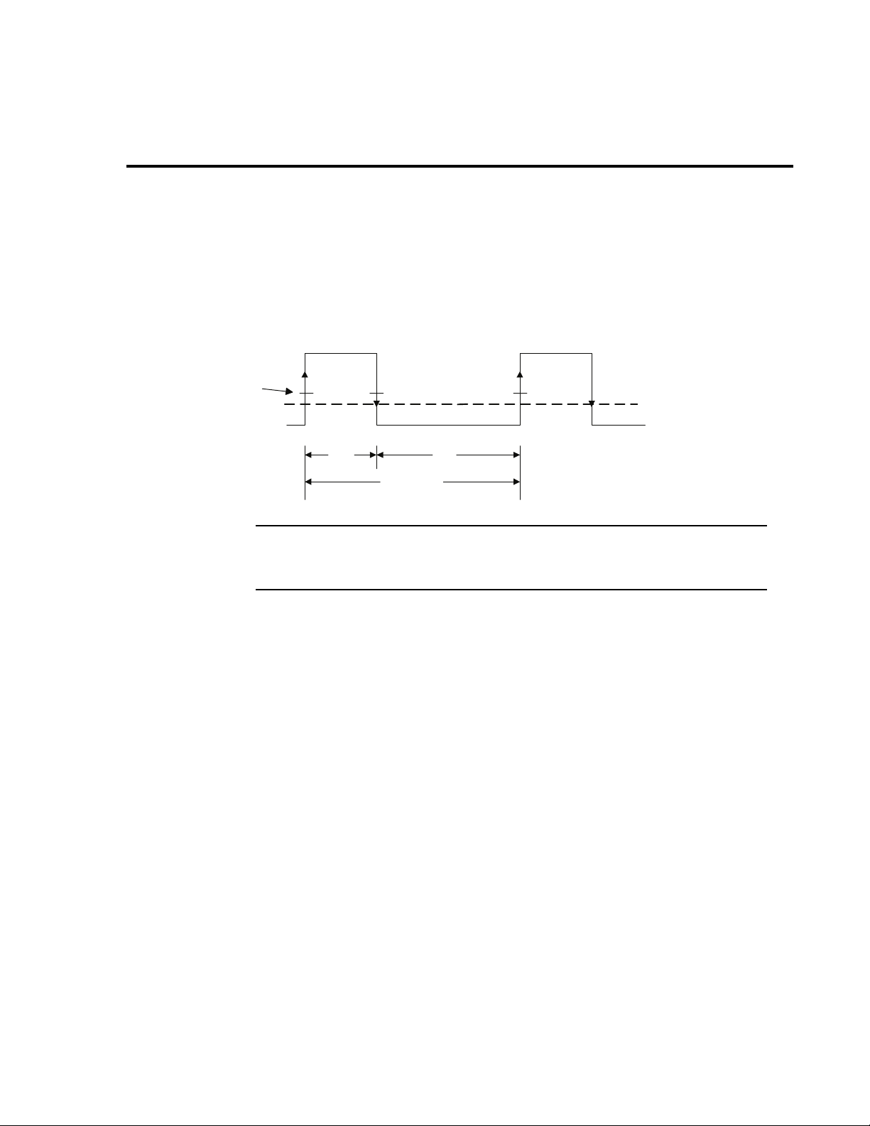
The high measurement is triggered on the rising edge of the pulse (Figure 7) and
integration is performed for the time specified for the high measurement. The falling
edge of the pulse triggers the low measurement, and an integration is performed
for the time specified for the low measurement. An average measurement is
triggered on the rising edge, and covers both the high and low periods of the pulse
as specified by the average measurement time setting. The Model
2308 computes
one measurement parameter, high, low, or average, at a time. The desired
measurement mode on the front panel is selected with the
NOTE See Section 3 in the Model 2308 Instruction Manual for
▲ or ▼ keys.
information on pulse current step and digitizing commands.
The GPIB commands TIMEOUT, SEARCH, DETECT, and FAST are available in
pulse current mode to optimize measurement speed. For the relevance and use
of these commands regarding a particular measurement application, refer to the
Model 2308 Instruction Manual, Section 3, Pulse Current Measurements.
The pulse measurement period can be selected manually or be automatically set
by the Model 2308. First, the user must specify a trigger level that serves as a
Page 20
Front-panel operation 13
Trigger
level
Average current
level
High current level
Low current level
High
time
Low
time
Average time
threshold to initiate the integration process. Once the trigger level is selected, the
output is turned on and the pulsed load measurement is operational, the 2308 can
be prompted to automatically determine the high time, low time, and average time
in pulsed current mode according to
Figure 7. These parameters may also be set
manually from the front panel or over the GPIB bus.
Figure 7
Pulsed waveform
NOTE The pulsed waveform in Figure 7 shows trigger level and the
high, low, and average times set by the Model 2308 using the
auto-time feature.
The pulsed response of a device is rarely a perfect square wave. Figure 8 shows
the current response of a typical GSM handset during the transmit portion of the
data frame. Using the built in auto-time feature with a trigger threshold of 0.2 amp
and no trigger delay, the Model
time, denoted by T
, to 533 μs. For this value of HIGH integration time, the effect
H1
2308 will automatically set the HIGH integration
of the current transient at the beginning of the pulse is included in the
measurement. Although in this example the effect of the current transient on the
measurement is small, the user can eliminate the effect of the transient by adding
a suitable amount of trigger delay. In this case, a delay of 100 μs is sufficient to
eliminate the effect of the transient, approximately 70 μs, from the measurement.
Accordingly, the HIGH integration time, T
, must be reduced, in this case 300 μs
H2
was chosen, so the integration time does not extend into a section of the pulse the
user does not want to measure.
Page 21

14 Front-panel operation
Figure 8
Eliminating the effect of a current transient on a pulse current measurement
NOTE In Figure 8, a trigger delay of 100 μs is used to eliminate the
effect of a current transient on the pulse current measurement.
Front-panel operation for performing pulse current
measurements
All of the following settings are available in submenus of PULSE CURRENT #1/#2
main menu items. Scroll through the main menu and when PULSE CURRENT #1/
#2 is displayed, press ENTER to access the sub-menus.
Turn on the output
Press the OPERATE key after setting the appropriate voltage and current limits for
the DUT.
Select CURRENT RANGE
Select appropriate range:
battery channel (#1) = 5 A, 500 mA, 50 mA, or 5 mA
charger channel (#2) = 5 A
Page 22

Front-panel operation 15
Set trigger level and range
TRIGGER LEVEL - For the battery channel (#1), use to specify the trigger level for
the 5 A, 500 mA, 50 mA, or 5 mA current ranges. Pulse current only works on the
5 A current range for the charger channel. Pulses less than the specified level are
not detected.
Battery channel (#1): The following table shows the trigger levels for each current
range along with trigger hysteresis:
Table 2
Current range and trigger level settings
Current range Trigger level setting Trigger hysteresis Setting step size
5 A 0-5 A 10 mA 5 mA
500 mA 0-500 mA 1 mA 0.5 mA or 500 μA
50 mA 0-50 mA 0.1 mA 0.05 mA or 50 μA
5 mA 0-5 mA 0.01 mA 0.005 mA or 5 μA
Trigger hysteresis is built into the hardware. If a pulse does not exceed the
appropriate hysteresis level, trigger detection will not occur. The trigger level
ranges for the battery channel (#1) are displayed as follows:
5 A range: PCUR TRIG LEV #1
A(5.0) 0.000 A
500 mA range: PCUR TRIG LEV #1
A(500) 0.0000 A
50 mA range: PCUR TRIG LEV #1
mA (50) 0.00000A
5 mA range: PCUR TRIG LEV #1
mA (5) 0.000000A
To change the trigger level setting for a current range, place the blinking cursor on
the “A” at the far right end of line two of the display, and press the
▲ or ▼ keys until
the desired current range is displayed at the beginning of line two. After keying in
the trigger level (in amps), press ENTER to update the displayed trigger level
setting for that current range only.
Charger channel (#2): Set the trigger level from 0 to 5 A in 5 mA steps. However,
there is approximately 10mA of trigger hysteresis built into the hardware.
Therefore, if a pulse does not exceed this level, trigger detection will not occur.
If the trigger level is incorrect or the DUT is not functioning properly, the PULSE
CURR TRIG NOT DETECTED message will be displayed. (See note No Pulses
Detected message on
page 18.)
Page 23

16 Front-panel operation
▲
▲
▲
▲
Integration time (manual setting) AVERAGE TIME, LOW TIME, and HIGH TIME
sub-menus
The values for HIGH, LOW, and AVERAGE time may be changed in 33.3333 μsec
intervals with the
833.33 msec.
Integration time (auto time setting) AUTO TIME submenu
Press ENTER when ACQUIRE TIMES appears on the display. If the correct trigger
level is selected in the previous step and the DUT is operating, the Model 2308 will
automatically determine the HIGH, LOW, and AVERAGE times. If the trigger level
is incorrect or the DUT is not functioning properly, the message PULSE CURR
TRIG NOT DETECTED will be displayed. (See note No Pulses Detected message
on
page 18.)
Timeout – TIMEOUT submenu
When the TIMEOUT value is reached, NO PULSE is displayed (top line of the frontpanel display). The value for TIMEOUT should be set to a value greater than the
pulse period. The default value is 1 second.
Trigger delay (if necessary) Channel #1 and Channel #2:
▲, ▼, , or keys. Range of values is 33.3333 μsec to
The trigger delay is changed in the TRIGGER DELAY submenu by using the ▲, ▼,
, or keys to scroll to the desired delay value. Range is 0 – 0.100sec in 10 μsec
increments.
NOTE The high, low, or average integration times can be set either
manually or automatically. When a pulse is detected, there is a
10µsec trigger latency before the integration time begins. An
additional user trigger delay can be set to allow the leading edge
pulse overshoot to settle. Regardless of the user trigger delay
setting, the internal trigger delay is always present.
Average readings count (if necessary) Channel #1 and Channel #2:
The AVERAGE READINGS submenu of the PULSE CURRENT #1/#2 menu item
is used to set the average readings count for pulse current measurements. This
count specifies the number of measurements (integrations) to average for each
reading. Range is 1–100.
Page 24

Front-panel operation 17
▲
▲
Pulse current display mode
Pulse current measurements are displayed with the pulse current display mode
selected. This display mode is selected as follows:
NOTE To display measured readings if the instrument is in the settings
mode, press the SET key until the blinking stops (the measured
readings can then be displayed). To determine if the instrument
is in the settings mode, check for a blinking cursor in a digit of
the voltage or current field (if present, the instrument is in the
settings mode).
1. Press the DISPLAY key to access the display menu.
2. If the desired active channel is not selected, use the or keys to scroll to
DISPLAY TYPE #1 or DISPLAY TYPE #2.
3. Press the ▲ or ▼ keys to scroll to PULSE CURRENT.
4. Press the ENTER key to select.
5. Use the ▲ or ▼ keys to scroll to the desired pulse measurement; PULSE HI,
PULSE LO, or PULSE AVG.
Page 25

18 Front-panel operation
NOTE No Pulses Detected message:
If no pulses are detected, current will not be measured (i.e., ----A), and the NO PULSE message will be displayed. The NO
PULSE message is displayed with dashes or the last valid pulse
reading. Dashes are shown if the pulse-current measurement
settings are not appropriate for detecting pulses. The last valid
pulse is shown if the pulse disappears while taking readings and
no change in pulse settings was made.
Pulses are not detected with the output OFF. With the output
ON, pulses will not be detected if the trigger level is too low or
too high. Adjust the trigger level as necessary and toggle back
to the display mode until pulse measurements are displayed.
If possible, the user should always use the analog output, an
oscilloscope, or a data acquisition card to determine the timing
and transient characteristics of a DUT. The waveform
information is very useful in setting up the Model 2308, reducing
setup time, and achieving maximum performance and
productivity. The voltage and current characteristics of the DUT
can be determined with a two-channel oscilloscope as shown in
Figure 9.
Page 26

Front-panel operation 19
Quick Disconnect
Connector
DUT
Source -
Source -
Sense -
Sense +
Source +
Source +
Twisted Pair
(5mA/50mA)
(0.5A/5A)
Load Test Leads
Channel 1
Channel 2
Oscilloscope
Figure 9
Determining voltage and current characteristics for battery channel
NOTE Figure 9 contains a simple circuit for determining the dynamic
voltage and current characteristics of the DUT.
Page 27

20 Front-panel operation
Programming examples: pulse current measurements
The following command sequence will return the average of 10 peak pulse current
measurements:
Battery channel (#1)
SENS:RANG 5 ‘ Select 5 A range.
VOLT 15 ‘ Set output voltage to 15 V.
CURR 0.75 ‘ Set current limit to 75 0mA.
OUTP ON ‘ Turn output on.
SENS:PCUR:SYNC ON ‘ Enable trigger synchronization.
SENS:PCUR:AVER 10 ‘ Set average count to 10.
SENS:PCUR:SYNC:TLEV 0.1 ‘ Set trigger level to 100 mA for 5 A trigger
SENS:PCUR:TIME:AUTO ‘ Set integration times automatically.
SENS:PCUR:SYNC:DEL 50e-3 ‘ Set trigger delay to 50 msec.
SENS:FUNC “PCUR” ‘ Select pulse current function.
SENS:PCUR:MODE HIGH ‘ Configure to measure peak pulse.
READ? ‘ Trigger 10 measurement conversions and
level range.
return the average of those 10 conversions.
The average of the 10 conversions is
displayed on the front panel. Each of the 10
conversions syncs to the rising edge.
Charger channel (#2)
SENS2:RANG 5 ‘ Select 5 A range.
SOUR2:VOLT 15 ‘ Set output voltage to 15 V.
SOUR2:CURR 0.75 ‘ Set current limit to 750 mA.
OUTP2 ON ‘ Turn output on.
SENS2:PCUR:SYNC ON ‘ Enable trigger synchronization.
SENS2:PCUR:AVER 10 ‘ Set average count to 10.
SENS2:PCUR:SYNC:TLEV 0.1 ‘ Set trigger level to 100 mA.
SENS2:PCUR:TIME:AUTO ‘ Set integration times automatically.
SENS2:PCUR:SYNC:DEL 50e-3 ‘ Set trigger delay to 50 msec.
SENS2:FUNC “PCUR” ‘ Select pulse current function.
SENS2:PCUR:MODE HIGH ‘ Configure to measure peak pulse (trigger
READ2 ‘ Trigger 10 measurement conversions and
on).
return the average of those 10 conversions.
The average of the 10 conversions is
displayed on the front panel. Each of the ten
conversions syncs to the rising edge.
Page 28
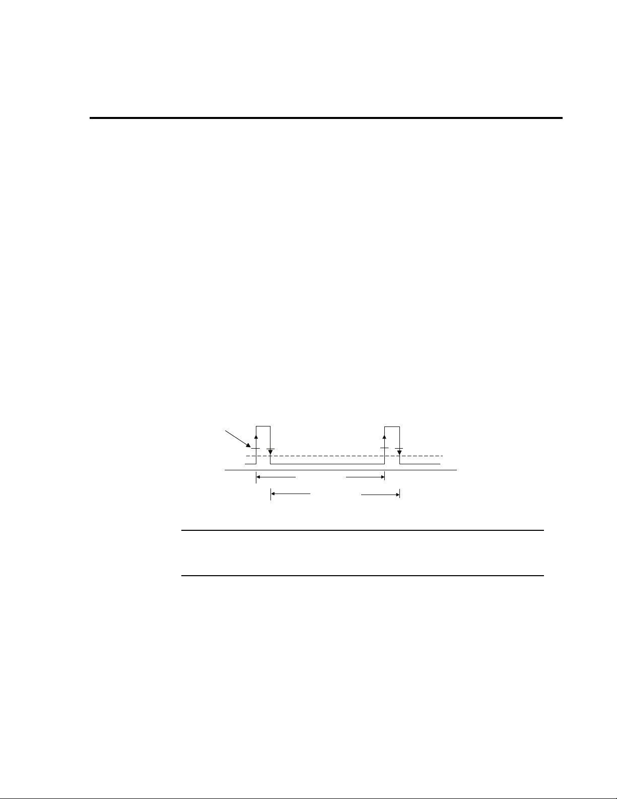
Long integration mode
Trigger
level
Average current
Integration time
(trigger set to rising)
Integration time
(trigger set to falling)
In the long integration mode, a current measurement results from a continuous
integration of the dynamic current for a period ranging from approximately 850 ms
to 60 sec set in 1msec increments. The Model 2308 can determine the integration
time automatically or the user can set the integration time manually from the front
panel. A pulse edge can be used to trigger the start of the measurement as shown
in
Figure 10. Select RISING to use a rising pulse edge to start the measurement.
Select FALLING to use a falling pulse edge to start the measurement. A third option
is available if you do not want measurements controlled by pulse edges. With
NEITHER selected, measurements will start as soon as the long integration
function is selected. Note that a pulse has to be detected before a RISING or
FALLING pulse edge can trigger a long integration measurement (see
level on page 22). To average over several pulse periods, the user must enter the
sum of the pulse periods as the integration time.
The GPIB commands TIMEOUT, SEARCH, DETECT, and FAST are available in
the long integration mode to optimize measurement speed. For the relevance and
use of these commands regarding a particular measurement application, refer to
the Model 2308 Instruction Manual, Section 4, Long Integration Measurements.
Figure 10
Pulsed waveform
Front-panel operation 21
Set trigger
NOTE The pulse waveform contained in Figure 10 shows trigger level
and the integration time used by the Model 2308 for long
integration measurements.
Front-panel operation for performing long integration
measurements
All of the following settings are available in submenus of the LONG INTEGRAT #1/
#2 main menu item. Scroll through the main menu until LONG INTEGRAT #1/#2
is displayed, press ENTER to access the submenus.
Page 29

22 Front-panel operation
Turn on the output
Press the OPERATE key after setting the appropriate voltage and current limits for
the DUT.
Select the current range
Select appropriate range:
battery channel (#1) = 5 A, 500 mA, 50 mA, or 5 mA
charger channel (#2) = 5 A
Set trigger level
TRIGGER LEVEL submenu
Before a RISING or FALLING pulse edge can trigger the start of a long integration,
the pulse must first be detected. TRIGGER LEVEL specifies the minimum pulse
level that will cause detection on the selected current range. For battery channel
(#1), all four current ranges can be used, and the trigger level setting
corresponding to the selected current range will be used to detect the pulse. For
the charger channel (#2), only the 5 A range is used for pulse measurements.
For battery channel (#1): Set the trigger level to either the 5 A, 500 mA, 50 mA, or
5 mA current range. For the 5 A current range, the trigger level can be set from 0
to 5 A in 5 mA steps. For the current 500 mA range, the trigger level can be set
from 0 to 500 mA in 0.5 mA steps. For the current 50 mA range, the trigger level
can be set from 0 to 50 mA in 0.05 mA steps. For the 5 mA current range, the trigger
level can be set from 0 to 5 mA in 0.005 mA steps.
The four trigger level ranges are displayed as follows using the TRIGGER LEVEL
menu option:
5 A range: PCUR TRIG LEV #1
A(5.0) 0.000 A
500 mA range: PCUR TRIG LEV #1
A(500) 0.0000 A
50 mA range: PCUR TRIG LEV #
mA (50) 0.00000A
5 mA range: PCUR TRIG LEV #
mA (5) 0.000000A
To change the trigger level setting for a current range, place the blinking cursor on
the “A” at the far right end of line two of the display, and press the
▲ or ▼ keys until
the desired current range is displayed at the beginning of line 2. After keying in the
trigger level (in amps), press ENTER to update the displayed trigger level setting
for that current range only.
Page 30

Front-panel operation 23
▲
▲
Charger channel (#2): Set the trigger level from 0 to 5 A in 5 mA steps for the 5 A
current range. Recall, you are only able to perform pulse current readings on 5 A
current range for charger channel.
If the trigger level is incorrect or the DUT is not functioning properly, the message
LONG INT TRIG NOT DETECTED will be displayed (see the LONG INT TRIG
NOT DETECTED note on
page 24).
Trigger edge – TRIGGER EDGE submenu
Toggle between the RISING, FALLING, and NEITHER settings with the ▲ or ▼
keys. With NEITHER selected, measurements will start as soon as the long
integration function is selected.
Timeout – TIMEOUT submenu
When the TIMEOUT value is reached, NO PULSE is displayed (top line of the frontpanel display). The value for TIMEOUT should be set to a value greater than the
long integration time for a long integration reading. This is true when the integration
time represents a single pulse period. However, when the integration time is used
to average multiple pulses then, set the TIMEOUT value to a value greater than a
single pulse period. The default setting is 16 ms.
Manually setting long integration time (INTEGRATION TIME submenu)
The value for LINT INT TIME for Channel #1 or Channel #2 can be specified in
0.850
sec to 60 sec (i.e. @ 60Hz) with the ▲, ▼, , or keys.
Automatically setting long integration time (AUTO TIME submenu)
Press ENTER when LINT AUTOTIME #1, #2, ACQUIRE TIMES appears on the
display. If the correct trigger level is selected in the previous step and the DUT is
operating, the Model 2308 will automatically determine the INTEGRATION times.
If the trigger level is incorrect or the DUT is not functioning properly, the message
LONG INT TRIG NOT DETECTED will be displayed. (See the LONG INT TRIG
NOT DETECTED note on
page 24.)
Long integration display mode
Long integration measurements are displayed with the long integration display
mode selected.
NOTE To display measured readings if the instrument is in the settings
mode, press the SET key until the blinking stops (the measured
readings can then be displayed). To determine if the instrument
is in the settings mode, check for a blinking cursor in a digit of
the voltage or current field (if present, the instrument is in the
setting mode).
Page 31

24 Front-panel operation
▲
▲
This display mode is selected as follows:
1. Press the DISPLAY key to access the display menu.
2. Press the or keys to scroll to DISPLAY TYPE #1 or DISPLAY TYPE #2.
3. Press the ▲ or ▼ keys to scroll to LONG INTEGRATION.
4. Press ENTER to select.=
5. To stop taking long integration readings, press any front-panel key.
6. As long as the instrument remains in the long integration display state, the
measurement process can be resumed by pressing the
NOTE LONG INT TRIG NOT DETECTED message:
▲ or ▼ keys.
This message may take a few seconds to appear. With the
trigger edge set to RISING or FALLING, this message may
appear if the level setting causes no rising or falling edge
detection. A valid trigger level is not required if the trigger edge
is set to NEITHER. For the battery channel (#1), this message
will only appear if the trigger level setting corresponds to the
selected current range. For the charger channel (#2), the trigger
level setting only applies to the 5 A current range.
If you select AUTO TIME to set the integration time, the pulse
timeout message LONG INT TRIG NOT DETECTED will display
if the output is OFF. This message indicates that the integration
time has not been updated. To update the integration time,
select AUTO TIME after the output is turned ON.
Programming examples: long integration measurements
The following command sequence will trigger and return one long integration
measurement:
Battery channel (#1)
SENS:RANG 5 ‘ Select 5 A range.
VOLT 15 ‘ Set output voltage to 15 V.
CURR 0.75 ‘ Set current limit to 750 mA.
OUTP ON ‘ Turn output on.
SENS:LINT:TEDG RISING ‘ Select rising trigger edge to initiate
SENS:LINT:TLEV 0.1 ‘ Set trigger level to 100mA for 5 A trigger
SENS:LINT:TIME:AUTO ‘ Set integration time automatically for
SENS:FUNC “LINT” ‘ Select long integration function.
measurement.
level range.
single pulse.
Page 32

Front-panel operation 25
READ? ‘ Trigger and return one reading and reading
shown on display.
Charger channel (#2)
SENS2:RANG 5 ‘ Select 5 A range.
SOUR2:VOLT 15 ‘ Set output voltage to 15 V.
SOUR2:CURR 0.75 ‘ Set current limit to 750 mA.
OUTP2 ON ‘ Turn output on.
SENS2:LINT:TEDG RISING ‘ Select rising trigger edge to initiate
measurement.
SENS2:LINT:TLEV 0.1 ‘ Set trigger level to 100 mA.
SENS2:LINT:TIME:AUTO ‘ Set integration time automatically for
single pulse.
SENS2:FUNC “LINT” ‘ Select long integration function.
READ2? ‘ Trigger and return one reading and reading
shown on display.
Page 33

26 Variable output impedance control on Battery Channel (#1)
▲
▲
Variable output impedance control on battery channel
The Model 2308 battery channel (#1) has a variable output
impedance control that can be used to simulate the impedance
of a battery pack.
To manually set the output impedance:
1. Press the MENU key.
2. Press the ▲ or ▼ keys to scroll through the menu items until OUTPUT
IMPEDANCE is displayed.
3. Press the ENTER key and use the ▲, ▼, , or keys to set an output
impedance between 0.00 Ω and 1.00 Ω in 0.01 Ω steps.
4. Press the ENTER key to program the value.
5. Press the MENU key to exit from the menu options.
To program the output impedance from a remote interface:
Send the OUTput:IMPedance<NRF> command over the GPIB bus.
NOTE The output impedance can be changed while the output is on.
Page 34

Variable output impedance control on Battery Channel (#1) 27
Variable output bandwidth
For high impedance test lead - DUT circuits, Model 2308 channel’s output could
become unstable. To improve stability, the channel’s output bandwidth can be
reduced. This action reduces voltage transient response, but the output becomes
more stable for a wider range of load impedances. The default bandwidth is: LOW
Bandwidth.
Front-panel operation for output bandwidth
The following settings are available in main menu under OUT BANDWIDTH #1,#2.
Use the
Tab le 3
GPIB commands
Command Description
:OUTPut:BANDwidth HIGH or LOW ‘ Specifies HIGH or LOW bandwidth when
:OUTPut2:BANDwidth HIGH or LOW ‘ Same as above, but for output channel #2.
▲ or ▼ keys to set the desired output bandwidth, either HIGH or LOW.
the output state is ON. When output is
OFF, the bandwidth is LOW, regardless of
the user setting. Once the output is ON,
the user setting takes effect.
Page 35

28 Variable output impedance control on Battery Channel (#1)
Source -
5/50 m
A
0.5/5
A
Oscilloscope
or Digitizer
Advanced features
Analog output
There are two analog output terminals: a 0.5/5 A output terminal for use when the
battery channel is programmed for either the 5 A or the 500 mA range and a 5/
50
mA output terminal for use when the battery channel is programmed for either
the 50 mA or the 5 mA range. Connect to the appropriate analog output terminal
and the Source - terminal.
The analog outputs provide a voltage output based on the measured current as
follows:
• 0.5/5 A Output referenced to Source - : 1 A/V (each volt out represents 1 A)
•5/50 mA Output referenced to Source - : 10 mA/V (each volt out represents
10
mA)
Each output internal impedances is nominally 1000 Ω.
Figure 11
Analog output
Page 36

Variable output impedance control on Battery Channel (#1) 29
Optimizing measurement speed
Auto Zero State
In general, to optimize speed of any application code, you should turn auto zero
off. To turn auto zero off, use the AUTO ZERO STATE option under the Main
Menu or send the following command over the bus: SYSTem :
The system auto zero state setting indicates whether background readings are
taken. A background reading is an internal calibration measurement taken by the
power supply between user triggered readings. The selected function dictates
how many background readings are taken between user triggered readings.
Certain settings, such as changes to integration time, force backgrounds to
update regardless of this state. Other changes, such as changing voltage level
settings, don't force backgrounds to update if already updated. When
backgrounds are forced to update, all must be refreshed before a user triggered
reading can be measured.
When auto zero state is set to ON, background readings continuously refresh by
cycling when the instrument is idle. When auto zero state is set to OFF,
background readings do not occur after being updated unless a change forces
them to update. When a change forces an update, the background readings get
updated once and stop until the next change forces an update.
AZERo:STATe 0.
To refresh the backgrounds when the state is OFF, set the state to ON then back
to OFF. This will refresh the backgrounds only once and stop after that.
Programming examples
Programming examples for methods of combining commands to speed up
measurements:
*rst ' restore factory default settings
syst:azer:stat 0 ' turn auto zero state off
disp:chan 1 ' sets active channel to battery
sens:func 'curr' ' select the current measurement function
volt 3 ' set output voltage to 3
curr 1 ' set current limit to 1
sens:nplc 0.5 ' set nplc to 0.5
NOTE For faster measurements, the NPLC can be as short as 0.002
outp on ' turn the output on
Page 37

30 Variable output impedance control on Battery Channel (#1)
read:five? ' switch to the 5mA current range, trigger a
current reading and return it
NOTE To optimize speed, the read:five? command combines range
changing, triggering a DC current measurement, and taking a
reading.
sens:func 'volt' ' select the voltage measurement function
read:fift? ' switch to the 50mA current range, trigger a
voltage reading and return it
NOTE To optimize speed, the read:fift? command combines
range changing, triggering a DC voltage measurement, and
taking a reading.
sens:func 'pcur' ' select the pulse current measurement
function
sens:pcur:sync:tlev:hund 0.3 ' set the trigger level to 300 mA for 500 mA
sens:pcur:sync:tlev:amp 0.7 ' set the trigger level to 700 mA for 5 A
sens:pcur:time:high 350e-6 ' set pulse high time to 350 microseconds
read:hund? ' switch to the 500 mA current range, trigger
current range
current range
a pulse current high reading and return it.
NOTE To optimize speed, the read:hund? command combines range
changing, triggering a pulse current measurement, and taking a
reading.
read:amp? ' switch to the 5 A current range, trigger a
pulse current high reading and return it.
NOTE To optimize speed, the read:amp? command combines range
changing, triggering a pulse current measurement, and taking a
reading.
Page 38

Index
A
Advanced features 28
Analog output 28
Optimizing measurement speed 29
D
DVM input mode 11
F
Front panel
Operation 7
operation for output bandwidth 27
operation for performing long
operation for performing pulse current
Front-panel operation
Average readings 9
Menu controls 7
NPLC rate 8
Programming examples 9
Setting the output voltage, current
Turning supply output ON/OFF 7
V and I display modes (Single and
Auto Zero State 29
Programming examples 29
integration measurements
measurements
range, and current limit
Dual)
8
14
7
21
V
Variable output bandwidth 27
Front-panel operation for output
bandwidth
Variable output impedance control on
battery channel
27
26
L
Long integration mode 21
M
Menu controls 7
P
Performance features 1
Programming examples
making voltage measurements with
the DVM
outputting and reading back V and I 9
pulse current measurements
programming examples 20
Proper connection of the supply
to the DUT 2
Pulse current mode 12
12
Page 39

Service Form
Model No. Serial No. Date
Name and Telephone No.
Company
List all control settings, describe problem and check boxes that apply to problem.
❏ Intermittent ❏ Analog output follows display ❏ Particular range or function bad; specify
❏ IEEE failure ❏ Obvious problem on power-up ❏ Batteries and fuses are OK
❏ Front panel operational ❏ All ranges or functions are bad ❏ Checked all cables
Display or output (check one)
❏ Drifts ❏ Unable to zero
❏ Unstable ❏ Will not read applied input
❏ Overload
❏ Calibration only ❏ Certificate of calibration required
❏ Data required
(attach any additional sheets as necessary)
Show a block diagram of your measurement system including all instruments connected (whether power is turned on
or not). Also, describe signal source.
Where is the measurement being performed? (factory, controlled laboratory, out-of-doors, etc.)
What power line voltage is used? Ambient temperature?°F
Relative humidity? Other?
Any additional information. (If special modifications have been made by the user, please describe.)
Be sure to include your name and phone number on this service form.
12/06
Page 40

12/06
Specifications are subject to change without notice.
All Keithley trademarks and trade names are the property of Keithley Instruments, Inc.
All other trademarks and trade names are the property of their respective companies.
A GREATER MEASURE OF CONFIDENCE
Keithley Instruments, Inc.
Corporate Headquarters • 28775 Aurora Road • Cleveland, Ohio 44139 • 440-248-0400 • Fax: 440-248-6168 • 1-888-KEITHLEY • www.keithley.com
 Loading...