

Page 1

Model 2302/2302-PJ/2306/2306-PJ
Keithley Instruments, Inc.
28775 Aurora Road
Cleveland, Ohio 44139
(440) 248-0400
Fax: (440) 248-6168
Battery/Charger Simulator
Packing List
F AST, SEARch, and DETect
This document provides information on Keithley’s Model 2302/2302-PJ/2306/2306-PJ Battery/Charger Simulators. FAST, SEARch, and DETect capabilities have been added for Pulse Current Measurements along
with a user set pulse current timeout. These features are available in Firmware Revision B05 and later (use
the REVISION NUMBER menu item located on the main menu to display the firmware revision). The new
pulse current F AST, SEARch, and DETect capabilities described in this addendum are bus only features (the
settings are ignored when operating the power supply in local mode — front panel) while the new variable
pulse current timeout feature can be accessed over the bus or from the front panel and used in local or remote
mode. This addendum provides information on using these new features.
New features
Front panel
The front panel can be used to set the new variable pulse current timeout feature. The menu item is located in
the PULSE CURRENT menu after the AUTO TIME menu item as shown in Table 2. Refer to "Using FAST,
SEARch, and DET ect" later in this addendum for detailed usage information on properly setting this TimeOUT
variable.
NOTE Pulse Current #1/#2, and Integration time settings (High, Low, Average, and Auto)
are contained in Table 1 for reference of the PULSE TIMEOUT menu item only —
no change to these menu items has occurred.
Table 1
Front panel menu item — Pulse Current Timeout
Menu item Description Reference
PULSE CURRENT #1/#2 Pulse current configuration. Section 3 of the 2302/
2306 Instruction Manual
HIGH TIME Set high time integration rate (in µsec.).
LOW TIME Set low time integration rate (in µsec.).
AVERAGE TIME Set average time integration rate (in µsec.).
AUTO TIME Set pulse integration rates automatically.
PULSE TIMEOUT Set pulse timeout (default is 1.000 seconds,
incremented in 1ms steps).
This document
PA-799 Rev. A / 6-01
Page 2

Bus commands
Table 2 contains the new bus commands.
Table 2
New bus commands (Firmware B05 and later)
Commands Description Default
SENSe[1]
:PCURrent
:FAST
:SEARch
:DETect
:TimeOUT
SENSe2
:PCURrent
:FAST
:SEARch
:DETect
:TimeOUT
SENSe subsystem for Channel #1 (battery channel):
Pulse current configuration:
Enable or disable pulse current fast readings.
Enable or disable pulse current search.
Enable or disable pulse current detection mode.
Specify length of timeout: 5ms -1000ms (1 second) incrementing in 1ms.
SENSe subsystem for Channel #2 (charger channel):
Pulse current configuration:
Enable or disable pulse current fast readings.
Enable or disable pulse current search.
Enable or disable pulse current detection mode.
Specify length of timeout: 5ms -1000ms (1 second) incrementing in 1ms.
OFF
ON
OFF
1 (sec)
OFF
ON
OFF
1 (sec)
Command notes
SENSe[1]: PulseCURrent:FAST <b>
SENSe2: PulseCURrent:FAST <b>
Refer to "Using FAST, SEARch, and DETect" for detailed usage information.
SENSe[1]:PulseCURrent:SEARch <b>
SENSe2: PulseCURrent:SEARch <b>
Refer to "Using FAST, SEARch, and DETect" for detailed usage information.
SENSe[1]: PulseCURrent:DET ect <b>
SENSe2: PulseCURrent:DET ect <b>
Refer to "Using FAST, SEARch, and DETect" for detailed usage information.
SENSe[1]:PulseCURrent:TimeOUT <NRf>
SENSe2: PulseCURrent: TimeOUT <NRf>
Refer to "Using FAST, SEARch, and DETect" for detailed usage information
on properly setting the TimeOUT variable.
Applies to battery channel (#1)
Applies to charger channel (#2)
Applies to battery channel (#1)
Applies to charger channel (#2)
Applies to battery channel (#1)
Applies to charger channel (#2)
Applies to battery channel (#1)
Applies to charger channel (#2)
Page 3
Using FAST, SEARch, and DET ect
Use FAST, SEARch, and DETect to control how background readings are taken. A background reading is a
measurement taken by the power supply between user triggered readings. The selected function dictates ho w
background readings are taken between user triggered readings.
For pulse current, a background reading inv olv es looking for the pulse and optionally generating a reading for
the user. The various settings of SEARch, FAST, and DETect allow the user to fine tune the function. This enables the function to perform the desired background readings (if any) between user triggered readings. The
default settings (FAST:OFF, SEARch:ON, and DETect:OFF) allow the pulse current background readings to
be taken. If no pulse is present, the setting of TimeOUT af fects ho w responsiv e the supply is to bus commands.
If a pulse is present, the search time affects how responsi ve the supply is to bus commands (refer to Figure 1).
T able 3 contains the available settings for F AST, SEARch, and DETect commands and a description of the resulting action.
In order to efficiently use FAST, SEARch, and DETect for pulse current measurements, the user must know
the approximate period of the expected pulse. TOUT (TimeOUT) specifies the timeout length for searching
for the pulse (default setting is 1 second). When the T OUT value is reached, NO PULSE is displayed (top line
of the front panel display) if default settings for FAST, SEARch, and DETect are used. See Table 3 for what
is displayed on the front panel display if the default settings are not used. Set the value for T OUT as follows:
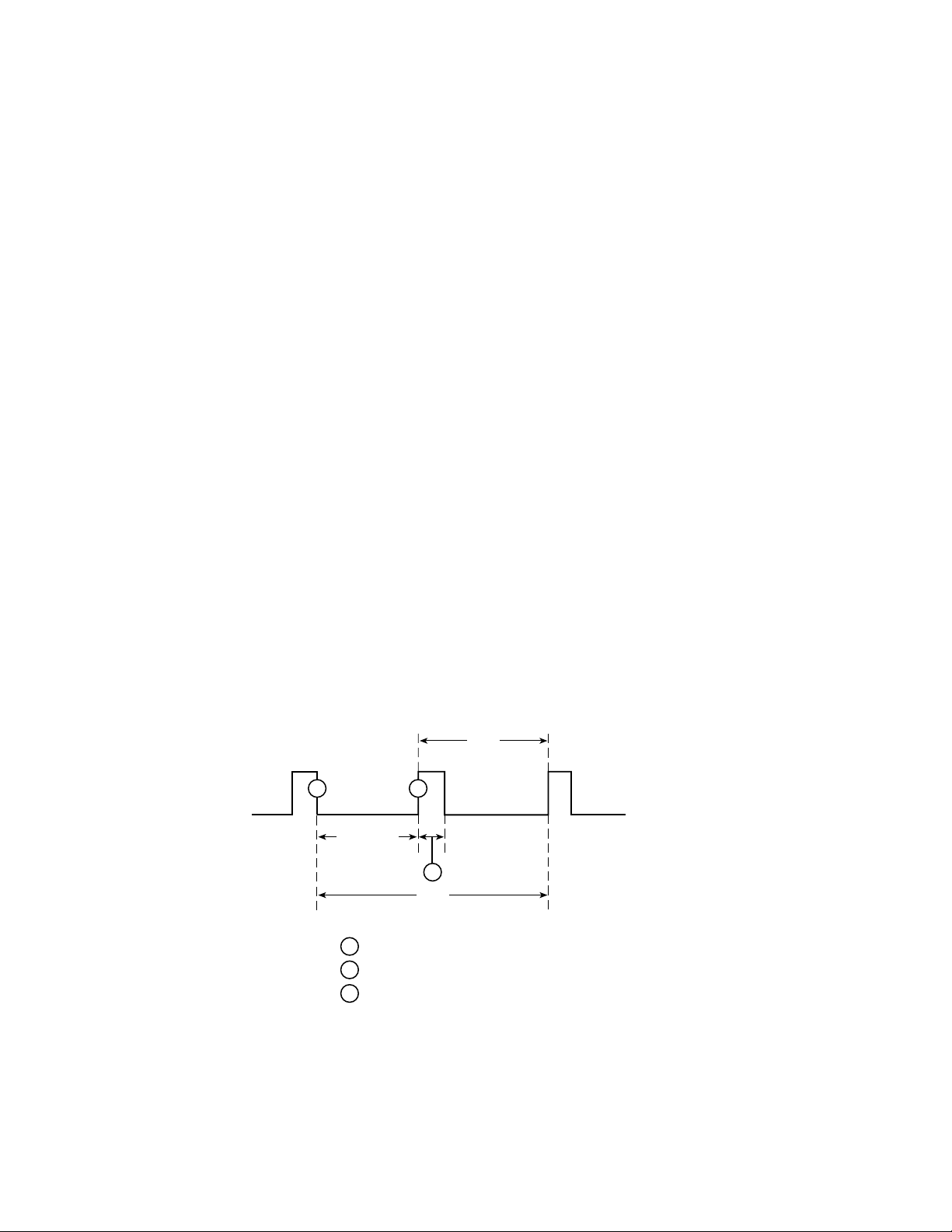
TOUT = Search Time + Period
Search Time = time allowed for detection of a pulse edge
Period = time between consecutive pulse edges
The timeout value should be set to allow sufficient time for detection of the pulse if the edge is just missed. In
Figure 1, (P) is the point where to start looking for the pulse. Since the rising edge was just missed, (D) will be
the first detectable rising edge. If the timeout is less than the search time, a pulse trigger timeout (due to TOUT)
may occur. Therefore, if the period = 0.4 seconds, a good T OUT v alue w ould be 0.5 seconds. A similar method
for selecting a TOUT value w ould be to use a value equal to 105% of the expected pulse period.
Figure 1
PCURent and SEARch time for pulse high measurement
Period
P
Search T ime
TOUT setting must account for Search Time and Period.
= Search for Pulse High edge started
P
= Reading time taken
R
= Detected pulse edge (Rising for pulse high measurements)
D
Search Time: Measured from when unit starts looking for the pulse until
the first detectable desired edge. This is a rising edge for HIGH and
AVG measurements and the falling edge for LOW measurements.
Period: Time between consecutive pulse edges.
D
R
TOUT
Page 4

NOTES If a pulse is not present, timeout needs to elapse (TOUT). The TOUT elapsing
paces the unit for processing bus commands.
If DETECT ON (only), search time needs to elapse before responding to a bus
command.
If SEARCH OFF or FAST ON, search time and TOUT are not incurred while
processing non-user triggered commands (refer to Section 9 of the 2302/2306
Instruction Manual for examples of user triggered commands).
Search time or TimeOUT needs to elapse when c hecking the TLEV command for
valid setting if enabled.
Table 3
PCURrent FAST, SEARch, and DETect commands
FAST SEARch DETect Description
ON
ON
ON
ON
ON
ON
OFF
OFF
ON
OFF
ON
OFF
Shaded cells designate command with precedence in each mode.
The unit is most responsive to b us commands in this mode. The supply does
not wait for TOUT or search time for background pulse current readings and
TLEV command checks. Front panel displays FAST HI / LO / AVG (in
remote mode) instead of PCUR HI / LO / AVG (in local mode). The bottom
line may show a previous reading or dashes based on what commands were
sent before when in remote mode.
With FAST set to ON, no pulse detection between user-triggered readings
occur, no checking for the parameter of PCUR TLEV commands to detect a
pulse occur, no setting of the pulse trigger timeout bits in the status model
between user-triggered readings occurs. The front panel has no indication
that pulse is not detected. Over the bus, an overflow reading indicates no
pulse detected when asked for a user triggered reading.
For triggered readings, the PTT (Pulse Trigger Timeout) bit is latched until
read so the bit may still be set in the status model from a previous timeout.
(See Section 7 of the 2302/2306 Instruction Manual for more information on
the status model. For triggered readings, the PTT (Pulse Trigger Timeout)
bit will be set if the reading times out and the pulse is not detected.
Page 5

Table 3 (cont.)
PCURrent FAST, SEARch, and DETect commands
FAST SEARch DETect Description
OFF
OFF
OFF ON
OFF
OFF
ON
OFF
ON This mode allows the user to know whether the pulse disappeared before a
The unit is more responsive to bus commands in this mode since the supply
does not need to wait for TOUT or search time for pulse current background
readings. However, the supply does need to wait for TOUT or search time
when checking the parameter setting for TLEV commands. Refer to Figure
1. Front panel displays "NO SEARCH" instead of PULSE HI / LO / AVG.
The bottom line may show a previous reading or dashes based on what commands were sent before when in remote mode.
The setting of the pulse trigger timeout bits in the status model will only
occur between user-triggered readings if TLEV commands are sent. For
triggered readings, the PTT (Pulse Trigger Timeout) bit will be set if the
reading times out and the pulse is not detected. Also, since the PTT bit is
latched until read, the bit may still be set in the status model from a previous
timeout. (See Section 7 of the 2302/2306 Instruction Manual for more information on the status model).
user-triggered reading is requested. The responsiveness of bus commands is
governed by TOUT (if no pulses are detected), or by search time (if pulses
are detected). Therefore, the longest response time to bus commands is
approximately the greater of either TOUT or search time values. Refer to
Figure 1.
If the pulse is detected, the front panel will display DETECT HI / LO / AV
on top line of display. If no pulses are detected, the front panel will display
"NO DETECT" as well as the PTT (Pulse Trigger Timeout) bit being set in
the status model. Since the PTT bit is latched until read, a query for the PTT
bit may indicate that pulse trigger timeout occurred although the display is
showing DETECT. (See Section 7 of the 2302/2306 Instruction Manual for
more information on the status model). The bottom line may show a previous reading or dashes based on what commands were sent before when in
remote mode.
Checking for the parameter of PCUR TLEV command may set the PTT
bit of the status model. For triggered readings, the PTT (Pulse Trigger
Timeout) bit will be set if the reading times out and the pulse is not detected.
Shaded cells designate command with precedence in each mode.
Page 6

Table 3 (cont.)
PCURrent FAST, SEARch, and DETect commands
FAST SEARch DETect Description
OFF ON OFF With DETect OFF, background pulse current measurements will occur
between user-triggered readings as well as pulse detection. If the pulse is
detected, the front panel will display PULSE HI / LO / AVG on the top line
of the display along with the reading on the bottom line. If no pulses are
detected, the front panel will display “NO PULSE” as well as the PTT
(Pulse Trigger Timeout) bit being set in the status model. Since the PTT bit
is latched, a query for the PTT bit may indicate that pulse trigger timeout
occurred although the display is displaying PULSE HI / LO / AVG and a
reading. (See Section 7 of the 2302/2306 Instruction Manual for more information on the status model). Checking for the parameter of PCUR TLEV
commands to detect a pulse may set the PTT bit. If detecting pulses, the supply's responsiveness to bus commands is affected by search time. If not
detecting pulses, the supply's responsiveness to bus commands is affected
by TOUT. Therefore, the longest response time to bus commands is approximately the greater of either TOUT or search time (refer Figure 1).
In this mode, the front panel will show PULSE HI / LO / AVG on the top
line with a reading on the bottom. Checking the parameter of PCUR TLEV
commands to detect a pulse may set the PTT bit of the status model if the
TLEV setting causes no pulse detection. For triggered readings, the PTT
(Pulse Trigger Timeout) bit will be set if the reading times out and the pulse
is not detected.
Shaded cells designate command with precedence in each mode.
Page 7

New SCPI programming commands
Common and Signal oriented measurement commands and queries
Three commands were added in firmware version B07 and greater to improve execution speed of the 2306
and 2306-PJ. Table 4 contains descriptions of the added commands.
NOTE No short form exists for any of the commands listed in this addendum.
Table 4
New commands in version B07
Command Description Default
BOTHTRG Triggers a reading on channel 1 and then channel 2. After this command
completes, the display is set for Channel #2.
BOTHFETCH? Responds with channel 1 and channel 2 readings in a single message.
The message contains a value for channel 1, a comma, and then a value
for channel 2. After this command completes, the display is set for Channel #1.
BOTHREAD? Triggers reading on channel 1 and then channel 2, then responds with
channel 1 and channel 2 readings in a single message. The message contains a value for channel 1, a comma, and then a value for channel 2.
After this command completes, the display is set for Channel #2.
N.A.
N.A.
N.A.
Command notes
When sending either the BOTHTRG or the BO THREAD? command, make note that the command is applied
to channel 1 (battery channel) first and then to channel 2 (charger channel). This allows both channels' triggers
to be controlled with a single bus command.
The BOTHTRG, BO THFETCH?, and BO THREAD? commands work with the Model 2306 and 2306-PJ, but
do not work with the 2302 or the 2302-PJ (i.e., the commands do not work with single channel models).
Page 8

Setups — Save, Recall, and Power-on
NOTE The output is always off when a memory location is recalled.
For Models 2306-PJ/2302-PJ starting with firmware version B07, setup 3 is unav ailable (only setups 0, 1, and
2 are available). Use the *SAV command to save the present instrument setup configuration in memory for
later recall with the *RCL command. Configure setups using the SAVE SETUP, RECALL SETUP, and
POWER ON SETUP items of the MENU (accessed by pressing the MENU key) or over the bus using the
following GPIB commands:
*SAV <NRf> — save Save present setup in memory
*RCL <NRf> — recall
Return to setup stored in memory
Parameters
<NRf> = 0 Memory location 0
1 Memory location 1
2 Memory location 2
SYSTem:POSetup <name> — save
Parameters
<name> = RST Power-up to *RST defaults
SAV0 Power-up to setup stored in memory location 0
SAV1 Power-up to setup stored in memory location 1
SAV2 Power-up to setup stored in memory location 2
Using these commands for setup 3 (such as *SAV3) will cause a parameter data out of range error.
Select power-on setup
 Loading...