

Tektronix 2302-2306 DC Power Supply User Manual

www.keithley.com
Model 2302/2302-PJ/2306/2306/2306-VS
Battery/Charger Simulator
Instruction Manual
2306-901-01 Rev. F / April 2008
A GREATER MEASURE OF CONFIDENCE


WARRANTY
Keithley Instruments, Inc. warrants this product to be free from defects in material and workmanship
for a period of one (1) year from date of shipment.
Keithley Instruments, Inc. warrants the following items for 90 days from the date of shipment:
probes, cables, software, rechargeable batteries, diskettes, and documentation.
During the warranty period, Keithley Instruments will, at its option, either repair or replace any product that
proves to be defective.
To exercise this warranty, write or call your local Keithley Instruments representative, or contact
Keithley Instruments headquarters in Cleveland, Ohio. You will be given prompt assistance and
return instructions. Send the product, transportation prepaid, to the indicated service facility. Repairs
will be made and the product returned, transportation prepaid. Repaired or replaced products are
warranted for the balance of the original warranty period, or at least 90 days.
LIMITATION OF WARRANTY
This warranty does not apply to defects resulting from product modification without Keithley
Instruments’ express written consent, or misuse of any product or part. This warranty also does not
apply to fuses, software, non-rechargeable batteries, damage from battery leakage, or problems
arising from normal wear or failure to follow instructions.
THIS WARRANTY IS IN LIEU OF ALL OTHER WARRANTIES, EXPRESSED OR IMPLIED,
INCLUDING ANY IMPLIED WARRANTY OF MERCHANTABILITY OR FITNESS FOR A
PARTICULAR USE. THE REMEDIES PROVIDED HEREIN ARE THE BUYER’S SOLE AND
EXCLUSIVE REMEDIES.
NEITHER KEITHLEY INSTRUMENTS, INC. NOR ANY OF ITS EMPLOYEES SHALL BE LIABLE
FOR ANY DIRECT, INDIRECT, SPECIAL, INCIDENTAL, OR CONSEQUENTIAL DAMAGES
ARISING OUT OF THE USE OF ITS INSTRUMENTS AND SOFTWARE, EVEN IF KEITHLEY
INSTRUMENTS, INC. HAS BEEN ADVISED IN ADVANCE OF THE POSSIBILITY OF SUCH
DAMAGES. SUCH EXCLUDED DAMAGES SHALL INCLUDE, BUT ARE NOT LIMITED TO: COST
OF REMOVAL AND INSTALLATION, LOSSES SUSTAINED AS THE RESULT OF INJURY TO ANY
PERSON, OR DAMAGE TO PROPERTY.
A G R E A T E R M E A S U R E O F C O N F I D E N C E
Keithley Instruments, Inc.
Corporate Headquarters • 28775 Aurora Road • Cleveland, Ohio 44139
440-248-0400 • Fax: 440-248-6168 • 1-888-KEITHLEY (1-888-534-8453) • www.keithley.com
3/07


Model 2302/2302-PJ/2306/2306-PJ/2306-VS
Battery/Charger Simulator
Instruction Manual
©2008, Keithley Instruments, Inc.
All rights reserved.
Cleveland, Ohio, U.S.A.
Sixth Printing, April 2008
Document Number: 2306-901-01 Rev. F

Manual Print History
The print history shown below lists the printing dates of all Revisions and Addenda created
for this manual. The Revision Level letter increases alphabetically as the manual undergoes sub
sequent updates. Addenda, which are released between Revisions, contain important change information that the user should incorporate immediately into the manual. Addenda are numbered
sequentially. When a new Revision is created, all Addenda associated with the previous Revi
sion of the manual are incorporated into the new Revision of the manual. Each new Revision
includes a revised copy of this print history page.
Revision A (Document Number 2306-901-01) .............................................................. March 1999
Addendum A (Document Number 2306-901-02) ........................................................ January 2000
Revision B (Document Number 2306-901-01) ................................................................. May 2000
Addendum B (Document Number 2306-901-02)..................................................... November 2000
Revision C (Document Number 2306-901-01) .......................................................... February 2001
Revision D (Document Number 2306-901-01) ................................................................ June 2003
Revision E (Document Number 2306-901-01) ................................................................. July 2003
-
-
All Keithley product names are trademarks or registered trademarks of Keithley Instruments, Inc.
Other brand names are trademarks or registered trademarks of their respective holders.

Safety Precautions
The following safety precautions should be observed before using this product and any associated instrumentation.
Although some instruments and accessories would normally be used with non-hazardous voltages, there are
situations where hazardous conditions may be present.
This product is intended for use by qualified personnel who recognize shock hazards and are familiar with the safety
precautions required to avoid possible injury. Read and follow all installation, operation, and maintenance
information carefully before using the product. Refer to the user documentation for complete product specifications.
If the product is used in a manner not specified, the protection provided by the product warranty may be impaired.
The types of product users are:
Responsible body is the individual or group responsible for the use and maintenance of equipment, for ensuring
that the equipment is operated within its specifications and operating limits, and for ensuring that operators are
adequately trained.
Operators use the product for its intended function. They must be trained in electrical safety procedures and proper
use of the instrument. They must be protected from electric shock and contact with hazardous live circuits.
Maintenance personnel perform routine procedures on the product to keep it operating properly, for example,
setting the line voltage or replacing consumable materials. Maintenance procedures are described in the user
documentation. The procedures explicitly state if the operator may perform them. Otherwise, they should be
performed only by service personnel.
Service personnel are trained to work on live circuits, perform safe installations, and repair products. Only properly
trained service personnel may perform installation and service procedures.
Keithley Instruments products are designed for use with electrical signals that are rated Measurement Category I
and Measurement Category II, as described in the International Electrotechnical Commission (IEC) Standard IEC
60664. Most measurement, control, and data I/O signals are Measurement Category I and must not be directly
connected to mains voltage or to voltage sources with high transient over-voltages. Measurement Category II
connections require protection for high transient over-voltages often associated with local AC mains connections.
Assume all measurement, control, and data I/O connections are for connection to Category I sources unless
otherwise marked or described in the user documentation.
Exercise extreme caution when a shock hazard is present. Lethal voltage may be present on cable connector jacks
or test fixtures. The American National Standards Institute (ANSI) states that a shock hazard exists when voltage
levels greater than 30V RMS, 42.4V peak, or 60VDC are present. A good safety practice is to expect that hazardous
voltage is present in any unknown circuit before measuring.
Operators of this product must be protected from electric shock at all times. The responsible body must ensure that
operators are prevented access and/or insulated from every connection point. In some cases, connections must be
exposed to potential human contact. Product operators in these circumstances must be trained to protect
themselves from the risk of electric shock. If the circuit is capable of operating at or above 1000 volts, no conductive
part of the circuit may be exposed.
Do not connect switching cards directly to unlimited power circuits. They are intended to be used with impedancelimited sources. NEVER connect switching cards directly to AC mains. When connecting sources to switching cards,
install protective devices to limit fault current and voltage to the card.
Before operating an instrument, make sure the line cord is connected to a properly grounded power recep tacle.
Inspect the connecting cables, test leads, and jumpers for possible wear, cracks, or breaks before each use.
When installing equipment where access to the main power cord is restricted, such as rack mounting, a separate
main input power disconnect device must be provided in close proximity to the equipment and within easy reach of
the operator.
11/07

For maximum safety, do not touch the product, test cables, or any other instruments while power is applied to the
!
circuit under test. ALWAYS remove power from the entire test system and discharge any capacitors before:
connecting or disconnecting cables or jumpers, installing or removing switching cards, or making internal changes,
such as installing or removing jumpers.
Do not touch any object that could provide a current path to the common side of the circuit under test or power line
(earth) ground. Always make measurements with dry hands while standing on a dry, insulated surface capable of
withstanding the voltage being measured.
The instrument and accessories must be used in accordance with specifications and operating instructions, or the
safety of the equipment may be impaired.
Do not exceed the maximum signal levels of the instruments and accessories, as defined in the specifications and
operating information, and as shown on the instrument or test fixture panels, or switching card.
When fuses are used in a product, replace with the same type and rating for continued protection against fire hazard.
Chassis connections must only be used as shield connections for measuring circuits, NOT as safety earth ground
connections.
If you are using a test fixture, keep the lid closed while power is applied to the device under test. Safe operation
requires the use of a lid interlock.
If a screw is present, connect it to safety earth ground using the wire recommended in the user documentation.
The symbol on an instrument indicates that the user shoul d refer to the operating instructions located in the
documentation.
The symbol on an instrument shows that it can source or measure 1000 volts or more, including the combined
effect of normal and common mode voltages. Use standard safety precautions to avoid personal contact with these
voltages.
The symbol on an instrument shows that the surface may be hot. Avoid personal contact to prevent burns.
The symbol indicates a connection terminal to the equipment frame.
If this symbol is on a product, it indicates that mercury is present in the display lamp. Please note that the lamp
must be properly disposed of according to federal, state, and local laws.
The WARNING heading in the user documentation explains dangers that might result in personal injury or death.
Always read the associated information very carefully before performing the indicated procedure.
The CAUTION heading in the user documentation explains hazards that could damage the instrument. Such
damage may invalidate the warranty.
Instrumentation and accessories shall not be connected to humans.
Before performing any maintenance, disconnect the line cord and all test cables.
To maintain protection from electric shock and fire, rep lacement components in mains circuits - including the power
transformer, test leads, and input jacks - must be purchased from Keithley Instruments. Standard fuses with
applicable national safety approvals may be used if the rating and type are the same. Other components that are
not safety-related may be purchased from other suppliers as long as they are equivalent to the original component
(note that selected parts should be purchased only through Keithley Instruments to maintain accuracy and
functionality of the product). If you are unsure about the applicability of a replacement component, call a Keithley
Instruments office for information.
T o clean an instrument, use a damp cloth or mild, water-based cleaner . Clean the exterior of the instrument only . Do
not apply cleaner directly to the instrument or allow liquids to enter or spill on the instrument. Products that consist
of a circuit board with no case or chassis (e.g., data acquisition board for installation into a computer) should never
require cleaning if handled according to instructions. If the board becomes contaminated and operation is affected,
the board should be returned to the factory for proper cleaning/servicing.

Table of Contents
1 Getting Started
General information ................................................................................................ 1-2
Warranty information ...................................................................................... 1-2
Contact information ......................................................................................... 1-2
Safety symbols and terms ................................................................................ 1-2
Specifications ................................................................................................... 1-2
Inspection ......................................................................................................... 1-3
Options and accessories ................................................................................... 1-3
Power supply overview ........................................................................................... 1-4
Remote display option ............................................................................................ 1-7
Power-up ................................................................................................................. 1-8
Line power connection ..................................................................................... 1-8
Power-up sequence .......................................................................................... 1-8
Fuse replacement ............................................................................................. 1-9
Display modes ....................................................................................................... 1-10
Default settings ..................................................................................................... 1-11
Setups — Save, Power-on, and Recall .......................................................... 1-14
Menu ..................................................................................................................... 1-14
Getting around the MENU ............................................................................. 1-17
SCPI programming ............................................................................................... 1-18
2 Basic Power Supply Operation
Test connections ...................................................................................................... 2-2
Remote sense ................................................................................................... 2-3
Local sense ....................................................................................................... 2-4
RFI considerations ........................................................................................... 2-4
Outputting voltage and current ............................................................................... 2-5
Setting voltage protection value ...................................................................... 2-5
Selecting proper current range ......................................................................... 2-6
Selecting current limit mode ............................................................................ 2-6
Editing output voltage and current limit values ............................................... 2-7
Pressing operate ............................................................................................... 2-9
Output bandwidth .................................................................................................. 2-10
Output impedance ................................................................................................. 2-11
Changing the battery channel’s output impedance ........................................ 2-11
SCPI programming — outputting voltage and current ......................................... 2-12
Command notes (outputting voltage and current) ......................................... 2-13
Reading back V and I ............................................................................................ 2-15
Actual V and I display mode ......................................................................... 2-15
Measurement configuration ........................................................................... 2-15
SCPI programming — measure V and I, and DVM input .................................... 2-17

Command notes (measure V and I, and DVM input) ................................... 2-18
Independent voltage measurements (DVM) ......................................................... 2-18
DVM input display mode .............................................................................. 2-18
Measurement configuration ........................................................................... 2-19
SCPI programming — DVM ................................................................................ 2-19
Sink operation ....................................................................................................... 2-19
Programming examples ........................................................................................ 2-21
Outputting and reading back V and I ............................................................ 2-21
DVM measurements ...................................................................................... 2-22
3 Pulse Current Measurements
Overview ................................................................................................................ 3-2
Trigger level .................................................................................................... 3-3
Trigger level range .......................................................................................... 3-3
Trigger delay ................................................................................................... 3-3
Integration times .............................................................................................. 3-4
Average readings count ................................................................................... 3-5
Measurement configuration .................................................................................... 3-6
Current range ................................................................................................... 3-6
Integration times .............................................................................................. 3-6
Average readings count ................................................................................... 3-7
Trigger delay, trigger level range, and trigger level ........................................ 3-7
Pulse current display mode ............................................................................. 3-9
Pulse current measurement procedure .................................................................. 3-10
Determining correct trigger level (pulse current) .......................................... 3-10
SCPI programming — pulse current measurements ............................................ 3-13
Command notes (pulse current measurements) ............................................ 3-15
Using FAST, SEARch, and DETect ............................................................. 3-17
Pulse current digitization ...................................................................................... 3-22
Pulse current step method ..................................................................................... 3-23
TLEV steps .................................................................................................... 3-23
Timeout setting .............................................................................................. 3-28
Integration time ............................................................................................. 3-29
Trigger level range ........................................................................................ 3-29
Programming examples ........................................................................................ 3-29
Pulse current measurements .......................................................................... 3-30
Pulse current digitization ............................................................................... 3-31
Pulse current STEP method (battery channel only) ...................................... 3-32
4 Long Integration Measurements
Overview ................................................................................................................ 4-2
Integration time ............................................................................................... 4-3
Trigger edge .................................................................................................... 4-3
Trigger level .................................................................................................... 4-4

Trigger level range ........................................................................................... 4-4
Pulse timeout .................................................................................................... 4-4
Measurement configuration .................................................................................... 4-7
Current range ................................................................................................... 4-7
Integration time ................................................................................................ 4-7
Pulse timeout .................................................................................................... 4-8
Trigger edge, trigger level, and trigger level range ......................................... 4-8
Long integration display mode ...................................................................... 4-10
Long integration measurement procedure ............................................................. 4-10
General notes ................................................................................................. 4-11
Determining correct trigger level (long integration) ...................................... 4-11
SCPI programming ............................................................................................... 4-13
Command notes (long integration measurements) ........................................ 4-15
Using FAST, SEARch, and DETect .............................................................. 4-15
Programming examples ......................................................................................... 4-19
5 Relay Control
Overview ................................................................................................................. 5-2
Connections ............................................................................................................. 5-4
Controlling relays .................................................................................................... 5-5
SCPI programming .......................................................................................... 5-6
6 External Triggering (Model 2306-VS Only)
Overview ................................................................................................................. 6-2
Model 2306-VS features .................................................................................. 6-2
Typical trigger sequence .................................................................................. 6-2
Trigger connections ................................................................................................. 6-3
Trigger connectors ........................................................................................... 6-3
Trigger signals ................................................................................................. 6-4
Commands .............................................................................................................. 6-5
Command notes ............................................................................................... 6-6
External trigger sequences ............................................................................. 6-12
Programming examples ......................................................................................... 6-16
7 GPIB Operation
Introduction ............................................................................................................. 7-2
GPIB bus connections ............................................................................................. 7-2
Primary address ....................................................................................................... 7-4
Setting the GPIB timeout for responses .................................................................. 7-4
Long integration readings ................................................................................ 7-5
Pulse current readings ...................................................................................... 7-5
MAV (Message Available Bit) ........................................................................ 7-5
General bus commands ........................................................................................... 7-6

Front panel aspects of GPIB operation ................................................................... 7-8
Programming syntax ............................................................................................... 7-9
8 Status Structure
Overview ................................................................................................................ 8-2
Clearing registers and queues ................................................................................. 8-4
Programming and reading registers ........................................................................ 8-5
Programming enable registers ......................................................................... 8-5
Reading registers ............................................................................................. 8-5
Status byte and service request (SRQ) ................................................................... 8-6
Status byte register .......................................................................................... 8-7
Service request enable register ........................................................................ 8-8
Serial polling and SRQ .................................................................................... 8-8
Status byte and service request commands ..................................................... 8-9
Status register sets ................................................................................................ 8-10
Register bit descriptions ................................................................................ 8-10
Condition registers ........................................................................................ 8-17
Event registers ............................................................................................... 8-17
Event enable registers .................................................................................... 8-18
Programming example — program and read measurement event register ... 8-19
Queues .................................................................................................................. 8-19
Output queue ................................................................................................. 8-20
Error queue .................................................................................................... 8-20
Programming example — read error queue .................................................. 8-21
9 Common Commands
Overview ................................................................................................................ 9-2
Command notes (IEEE-488.2 common commands and queries) ................... 9-3
10 Signal Oriented Measurement Commands
Overview .............................................................................................................. 10-2
Command notes (Signal oriented measurement commands and queries) ..... 10-3
11 DISPlay, FORMat, and SYSTem
DISPlay subsystem ............................................................................................... 11-2
Command notes (SCPI commands — display) ............................................. 11-2
FORMat subsystem .............................................................................................. 11-4
Command notes (SCPI commands — data format) ...................................... 11-5
:SYSTem subsystem ............................................................................................. 11-7
Command notes (SCPI commands — system) ............................................. 11-8

12 SCPI Tables
SCPI command subsystems reference tables ........................................................ 12-2
13 Performance Verification
Introduction ........................................................................................................... 13-2
Verification test requirements ............................................................................... 13-3
Environmental conditions .............................................................................. 13-3
Warm-up period ............................................................................................. 13-3
Line power ..................................................................................................... 13-3
Recommended test equipment .............................................................................. 13-4
Resistor connections ...................................................................................... 13-4
Resistor considerations .................................................................................. 13-4
Verification limits ................................................................................................. 13-5
Example limits calculation ............................................................................. 13-5
Performing the verification test procedures .......................................................... 13-5
Test summary ................................................................................................. 13-5
Test considerations ........................................................................................ 13-5
Output voltage accuracy ........................................................................................ 13-6
Voltage readback accuracy ................................................................................... 13-8
Compliance current accuracy ................................................................................ 13-9
Current readback accuracy .................................................................................. 13-11
5A range readback accuracy ........................................................................ 13-11
5mA range readback accuracy ..................................................................... 13-12
500mA range readback accuracy ................................................................. 13-14
Digital voltmeter input accuracy ......................................................................... 13-16
14 Calibration
Introduction ........................................................................................................... 14-2
Environmental conditions ..................................................................................... 14-2
Temperature and relative humidity ................................................................ 14-2
Warm-up period ............................................................................................. 14-2
Line power ..................................................................................................... 14-2
Calibration considerations ..................................................................................... 14-3
Calibration cycle ............................................................................................ 14-3
Recommended calibration equipment ................................................................... 14-3
Resistor connections ...................................................................................... 14-4
Resistor considerations .................................................................................. 14-4
Front panel calibration .......................................................................................... 14-4
Remote calibration .............................................................................................. 14-11
Remote calibration display .......................................................................... 14-11
Remote calibration procedure ...................................................................... 14-12
Changing the calibration code ............................................................................. 14-17
Changing the code from the front panel ...................................................... 14-17

Changing the code by remote ...................................................................... 14-17
Resetting the calibration code ..................................................................... 14-18
Viewing calibration date and count .................................................................... 14-19
Viewing date and count from the front panel .............................................. 14-19
Acquiring date and count by remote ........................................................... 14-19
15 Disassembly
Introduction .......................................................................................................... 15-2
Handling and cleaning .......................................................................................... 15-2
Handling PC boards ...................................................................................... 15-2
Solder repairs ................................................................................................. 15-2
Static sensitive devices .................................................................................. 15-3
Assembly drawings .............................................................................................. 15-3
Disassembly procedures ....................................................................................... 15-4
Case cover removal ....................................................................................... 15-4
Analog board removal .................................................................................. 15-4
Digital board removal .................................................................................... 15-5
Front panel disassembly ................................................................................ 15-5
Removing mechanical components ............................................................... 15-5
Instrument reassembly .......................................................................................... 15-6
16 Replaceable Parts
Introduction .......................................................................................................... 16-2
Ordering information ............................................................................................ 16-2
Factory service ...................................................................................................... 16-2
Parts lists and component layouts ......................................................................... 16-2
A Specifications
B Error and Status Messages
C Calibration Reference
Introduction ............................................................................................................ C-2
Command summary ........................................................................................ C-2
Miscellaneous commands ....................................................................................... C-2
Detecting calibration errors .................................................................................... C-6
Reading the error queue .................................................................................. C-6
Error summary ................................................................................................. C-6
Status byte EAV (Error Available) bit ............................................................ C-6
Generating an SRQ on error ............................................................................ C-6
Detecting calibration step completion .................................................................... C-8
Using the *OPC command .............................................................................. C-8
Using the *OPC? query ................................................................................... C-8

Generating an SRQ on calibration complete .................................................. C-8
D Calibration Program
Introduction ............................................................................................................ D-2
Computer hardware requirements .......................................................................... D-2
Software requirements ........................................................................................... D-2
Calibration equipment ............................................................................................ D-2
General program instructions ................................................................................. D-3
E Applications Guide
Simulating battery impedance ................................................................................ E-2
Variable output impedance control on channel #1 ......................................... E-2
F Model 2302 Specifics
General information ................................................................................................ F-2
Specifications ................................................................................................... F-2
Power supply overview .................................................................................... F-2
Operational differences ........................................................................................... F-2
Front panel operation ....................................................................................... F-2
SCPI operation ................................................................................................. F-2
Calibration ....................................................................................................... F-3
G 488.1 Protocol
GPIB 488.1protocol ............................................................................................... G-2
Selecting the 488.1 protocol ........................................................................... G-2
Protocol differences ........................................................................................ G-3
Trigger on talk both channels ................................................................................. G-5
Bus commands ................................................................................................ G-5
Command notes .............................................................................................. G-6
Trigger continuous mode ....................................................................................... G-6
Bus commands ................................................................................................ G-6
Command notes .............................................................................................. G-7
Using trigger continuous mode ....................................................................... G-7
Index ........................................................................................................................ 1-1


List of Illustrations
1 Getting Started
Figure 1-1 Model 2306 and 2306-PJ dual channel battery/charger simulator ..................... 1-4
Figure 1-2 Model 2306-VS dual channel battery/charger simulator .................................... 1-5
Figure 1-3 Simplified power supply diagram ....................................................................... 1-6
Figure 1-4 2304-DISP Remote display option (2306-DISP similar) ................................... 1-7
Figure 1-5 Fuse drawer location ........................................................................................... 1-9
2 Basic Power Supply Operation
Figure 2-1 Four-wire sense connections for battery and charger channels .......................... 2-3
Figure 2-2 Local sense connections ..................................................................................... 2-4
Figure 2-3 Sink operation ................................................................................................... 2-20
Figure 2-4 Preferred method .............................................................................................. 2-20
3 Pulse Current Measurements
Figure 3-1 Pulse current measurement ................................................................................. 3-2
Figure 3-2 Trigger delay for high pulse current measurement ............................................. 3-4
Figure 3-3 Determining voltage and current characteristics .............................................. 3-11
Figure 3-4 PCURent and SEARch time for pulse high measurement ................................ 3-18
Figure 3-5 Sample pulse forms for step method ................................................................ 3-25
Figure 3-6 Sample one-shot only pulses for step method .................................................. 3-25
Figure 3-7 Sample :STEP Pulse measurement ................................................................... 3-26
Figure 3-8 Pulse form with rise and fall steps .................................................................... 3-26
Figure 3-9 Pulse form with down steps first (600μsec step duration) ................................ 3-27
4 Long Integration Measurements
Figure 4-1 Steady state for waveforms based on low pulse times ........................................ 4-3
Figure 4-2 Long integration, search, and reading time comparison ..................................... 4-5
Figure 4-3 TOUT and search time ...................................................................................... 4-16
5 Relay Control
Figure 5-1 External source relay control .............................................................................. 5-3
Figure 5-2 Internal source relay control ............................................................................... 5-3
Figure 5-3 Relay connector (9-pin D-sub) ........................................................................... 5-4
6 External Triggering (Model 2306-VS Only)
Figure 6-1 Typical trigger sequence ..................................................................................... 6-3
Figure 6-2 Model 2306-VS rear panel trigger connectors .................................................... 6-3
Figure 6-3 Trigger input signal ............................................................................................. 6-4
Figure 6-4 Trigger output signal ........................................................................................... 6-4

7 GPIB Operation
Figure 7-1 IEEE-488 connector ........................................................................................... 7-2
Figure 7-2 Daisy chaining .................................................................................................... 7-3
8 Status Structure
Figure 8-1 Status model structure ........................................................................................ 8-3
Figure 8-2 16-bit status register ........................................................................................... 8-5
Figure 8-3 Status byte and service request .......................................................................... 8-6
Figure 8-4 Standard event status ........................................................................................ 8-11
Figure 8-5 Operation event status ...................................................................................... 8-13
Figure 8-6 Measurement event status ................................................................................ 8-15
Figure 8-7 Questionable event status ................................................................................. 8-16
11 DISPlay, FORMat, and SYSTem
Figure 11-1 IEEE-754 single precision data format ............................................................ 11-5
Figure 11-2 IEEE-754 double precision data format ........................................................... 11-6
13 Performance Verification
Figure 13-1 Connections for voltage verification tests ........................................................ 13-6
Figure 13-2 Connections for output current and 5A range current verification tests .......... 13-9
Figure 13-3 Connections for 5mA current verification tests ............................................. 13-12
Figure 13-4 Connections for 500mA current verification tests ......................................... 13-14
Figure 13-5 Connections for DVM accuracy verification ................................................. 13-16
14 Calibration
Figure 14-1 Connections for voltage calibration ................................................................. 14-6
Figure 14-2 Connections for 5A/500mA current calibration ............................................... 14-7
Figure 14-3 Connections for 5mA range calibration ........................................................... 14-9
Figure 14-4 Jumper connections to reset calibration code ................................................. 14-18
E Applications Guide 1
Figure E-1 Battery schema.tic .............................................................................................. E-2
Figure E-2 Actual battery pack terminal voltage during GSM phone simulation ................ E-3
Figure E-3 Simulated GSM phone current profile ............................................................... E-4
Figure E-4 Electronic resistance of NiCd, NiMH, and Li ion battery packs ....................... E-4
Figure E-5 Effect of the variable output impedance control ................................................ E-5
Figure E-6 Li ion voltage drop during the transmit portion of the pulse ............................ E-6
Figure E-7 Model 2306 voltage drop during the transmit portion of the pulse .................... E-7
F Model 2302 Specifics 1
Figure F-1 Model 2302 and 2302-PJ single channel battery simulator ............................... F-3

List of Tables
1 Getting Started
Table 1-1 Display samples ................................................................................................ 1-11
Table 1-2 Factory defaults (RST) ...................................................................................... 1-12
Table 1-3 Main MENU structure (accessed by pressing the MENU
2 Basic Power Supply Operation
Table 2-1 Current ranges ..................................................................................................... 2-6
Table 2-2 Output bandwidth setting for a channel ............................................................ 2-10
Table 2-3 SCPI command summary — outputting voltage and current ........................... 2-12
Table 2-4 SCPI commands — measure V and I, and DVM input .................................... 2-17
3 Pulse Current Measurements
Table 3-1 TRIG NOT DETECTED message .................................................................... 3-12
Table 3-2 SCPI commands — pulse current measurements ............................................. 3-13
Table 3-3 PCURrent FAST, SEARch, and DETect commands ........................................ 3-20
Table 3-4 Setting UP and DOWN commands .................................................................. 3-24
Table 3-5 Sample TLEV values for Figure 3-8 ................................................................. 3-27
Table 3-6 Sample integration times .................................................................................. 3-29
4 Long Integration Measurements
Table 4-1 TRIG NOT DETECTED message .................................................................... 4-12
Table 4-2 SCPI commands — long integration measurements ........................................ 4-13
Table 4-3 FAST, SEARch, and DETect command reference ............................................ 4-16
key on the Front Panel) ..................................................................................... 1-15
5 Relay Control
Table 5-1 Relay pinouts (for Figure 5-3) ............................................................................. 5-4
Table 5-2 SCPI command — output relay control .............................................................. 5-6
6 External Triggering (Model 2306-VS Only)
Table 6-1 Model 2306-VS external trigger commands ....................................................... 6-5
Table 6-2 External trigger sequences for various operating modes .................................. 6-14
7 GPIB Operation
Table 7-1 General bus commands ....................................................................................... 7-6

8 Status Structure
Table 8-1 Common and SCPI commands — reset registers and clear queues ................... 8-4
Table 8-2 Command commands — status byte and service request enable registers ........ 8-9
Table 8-3 Common and SCPI commands — condition registers ..................................... 8-17
Table 8-4 Common and SCPI commands — event registers ........................................... 8-17
Table 8-5 Common and SCPI commands — event enable registers ................................ 8-18
Table 8-6 SCPI commands — error queue ....................................................................... 8-21
9 Common Commands
Table 9-1 IEEE-488.2 common commands and queries .................................................... 9-2
Tabl e 9-2 *OPC and *OPC? commands ............................................................................ 9-4
10 Signal Oriented Measurement Commands
Table 10-1 Signal oriented measurement command summary .......................................... 10-2
11 DISPlay, FORMat, and SYSTem
Table 11-1 SCPI commands — display ............................................................................. 11-2
Table 11-2 SCPI commands — data format ....................................................................... 11-4
Table 11-3 SCPI commands — system .............................................................................. 11-7
12 SCPI Tables
Table 12-1 Display command summary (refer to Display subsystem in Section 11) ........ 12-3
Table 12-2 FORMat command summary (refer to Format subsystem in Section 11) ....... 12-4
Table 12-3 OUTPut command summary (refer to Tables 2-3 and 5-2) ............................. 12-5
Table 12-4 SENSe command summary (refer to Tables 2-3, 3-2, and 4-2) ....................... 12-6
Table 12-5 SOURce command summary (refer to Table 2-3) ......................................... 12-16
Table 12-6 STATus command summary (refer to Section 8) ........................................... 12-17
Table 12-7 SYSTem command summary (refer to System subsystem in Section 11) ..... 12-19
Table 12-8 Model 2306-VS external trigger command summary (refer to Section 6) .... 12-20
13 Performance Verification
Table 13-1 Recommended verification equipment ............................................................. 13-4
Table 13-2 Output voltage accuracy limits ......................................................................... 13-7
Table 13-3 Voltage readback accuracy limits ..................................................................... 13-8
Table 13-4 Compliance current accuracy limits ............................................................... 13-10
Table 13-5 5A range current readback accuracy limits .................................................... 13-11
Table 13-6 5mA range current readback accuracy limits ................................................. 13-13
Table 13-7 500mA range current readback accuracy limits ............................................. 13-15
Table 13-8 Digital voltmeter input accuracy limits .......................................................... 13-17

14 Calibration
Table 14-1 Recommended calibration equipment .............................................................. 14-3
Table 14-2 Model 2306 front panel calibration summary .................................................. 14-5
Table 14-3 Remote calibration summary .......................................................................... 14-16
16 Replaceable Parts
Table 16-1 Model 2306 digital board parts list ................................................................... 16-3
Table 16-2 Model 2306 analog board parts list .................................................................. 16-7
Table 16-3 Model 2306 display board parts list ................................................................ 16-14
Table 16-4 Model 2306 mechanical parts list ................................................................... 16-15
Table 16-5 Model 2306-VS digital board parts list .......................................................... 16-16
Table 16-6 Model 2306-VS display board parts list ......................................................... 16-21
Table 16-7 Model 2306-VS analog board parts list .......................................................... 16-22
Table 16-8 Model 2306-VS mechanical parts list ............................................................. 16-31
B Error and Status Messages
Table B-1 Error and status messages (all models) .............................................................. B-2
Table B-2 Error and status messages (Model 2306-VS only) ............................................ B-5
C Calibration Reference
Table C-1 Remote calibration command summary ............................................................ C-3
Table C-2 Calibration errors ............................................................................................... C-7
G 488.1 Protocol
Table G-1 Trigger on talk bus commands ........................................................................... G-5
Table G-2 Trigger continuous bus commands .................................................................... G-6
Table G-3 Trigger continuous mode programming example .............................................. G-8


1
Getting Started
• General information — Provides general information including warranty information,
contact information, safety symbols and terms, inspection and available options and
accessories.
• Power supply overview — Summarizes the capabilities of the power supply.
• Remote display option — Explains how to use the optional Model 2306-DISP Display
Module.
• Power-up — Covers line power connection, the power up sequence, and fuse
replacement.
• Display modes — Explains the four display modes of the power supply.
• Default settings — Lists the factory default settings, and explains how to save and recall
settings.
• Menu — Provides a table that summarizes the menu items and includes rules to navigate
the menu structure.
• SCPI programming — Explains how SCPI commands are presented in this manual.
NOTES This manual covers Keithley Models 2302, 2302-PJ, 2306, 2306-PJ, and 2306-VS
simulators (power supplies). Since the Model 2302 and 2302-PJ are single channel
battery simulators, functions related to the second channel (i.e., the charger channel)
are not available for the Model 2302 and 2302-PJ. Therefore:
• battery and charger channel features contained in this manual apply for the
Models 2306, 2306-PJ, and 2306-VS.
• only battery channel features contained in this manual apply for the Model 2302
and 2302-PJ
Refer to Appendix F for specific Model 2302 and 2302-PJ information.
Information contained in this section applies to all power supply channels (unless
otherwise noted). In this manual, channel 1 refers to the battery channel while
channel 2 refers to the charger channel (2306, 2306-PJ, and 2306-VS feature only).

1-2 Getting Started
General information
Warranty information
Warranty information is located at the front of this manual. Should your power supply require
warranty service, contact the Keithley representative or authorized repair facility in your area for
further information. When returning the instrument for repair, be sure to fill out and include the
service form at the back of this manual to provide the repair facility with the necessary
information.
Contact information
If you have any questions after reviewing this information, please contact your local Keithley
representative or call one of our Applications Engineers at 1-800-348-3735 (U.S. and Canada
only). Worldwide phone numbers are listed at the front of this manual.
Safety symbols and terms
Keithley uses a standard set of safety symbols and terms that may be found on an instrument
or in its manual.
The ! symbol on an instrument indicates that the user should refer to the operating
instructions located in the manual.
The symbol on an instrument shows that high voltage may be present on the terminal(s).
Use standard safety precautions to avoid personal contact with these voltages.
The WA R NI N G heading used in a manual explains dangers that might result in personal
injury or death. Always read the associated information very carefully before performing the
indicated procedure.
The CAUTION heading used in a manual explains hazards that could damage the instrument.
Such damage may invalidate the warranty.
Specifications
Full power supply specifications can be found in Appendix A of this manual.

Inspection
The power supply was carefully inspected electrically and mechanically before shipment.
After unpacking all items from the shipping carton, check for any obvious signs of physical
damage that may have occurred during transit. (Note: There may be a protective film over the
display lens, which can be removed.) Report any damage to the shipping agent immediately.
Save the original packing carton for possible future shipment. The following items are included
with every order:
If an additional manual is required, order the manual package. The manual package includes
a manual and any pertinent addenda.
Any improvements or changes concerning the instrument or manual will be explained in an
addendum included with the manual. Be sure to note these changes and incorporate them into
the manual.
Getting Started 1-3
• Model 2306 Dual Channel Battery/Charger Simulator with line cord
• Quick Disconnect Output/DVM Input Connector (2)
• Accessories as ordered
• Certificate of calibration
• Product Information CD-ROM that contains PDFs of Model 2302/2306 Instruction
Manual and Model 2302/2306 Quick Results Guide
• Model 2302/2306 Quick Results Guide (Hardcopy)
• Model 2306-VS External Trigger Functionality Flowchart (Hardcopy)
Options and accessories
The following options and accessories are available for the power supply.
• 2304-DISP and 2306-DISP remote display unit (2304-DISP cannot be used with the
2306-VS, use the 2306-DISP instead)
Model
• Shielded IEEE-488 cable, 1m (3.3 ft) (P/N 7007-1)
• Shielded IEEE-488 cable, 2m (6.6 ft) (P/N 7007-2)
• Single fixed rack mount kit (P/N 4288-1)
• Dual fixed rack mount kit (P/N 4288-2)
• IEEE-488 Interface/controller for the PCI bus (P/N KPCI-488)
• IEEE Interface card for IBM PC/AT (full slot) (P/N KPC-488-2AT)
1-4 Getting Started
WARNING:NO INTERNAL OPERATOR SERVICABLE PARTS,SERVICE BY QUALIFIED PERSONNEL ONLY.
CAUTION:FOR CONTINUED PROTECTION AGAINST FIRE HAZARD,REPLACE FUSE WITH SAME TYPE AND RATING.
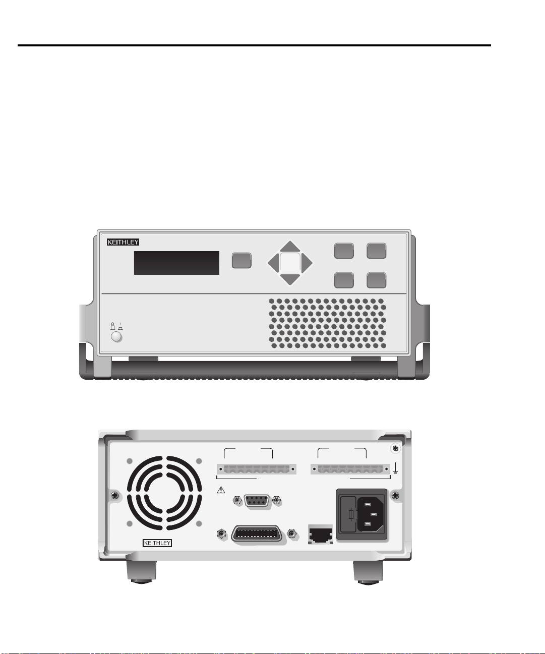
Power supply overview
The Model 2306 power supply (dual channel battery/charger simulator — see Figure 1-1) can
simulate a battery (Channel #1) or a charger (Channel #2). Figure 1-2 shows the Model 2306-VS
front and rear panels.
NOTE Except where noted, all information in this manual pertaining to the Model 2306 and
2306-PJ also applies to the Model 2306-VS. See Section 6 for information on opera
tion specific to the Model 2306-VS.
Figure 1-1
Model 2306 and 2306-PJ dual channel battery/charger simulator
-
POWER
A) Front Panel
2306 DUAL CHANNEL BATTERY/CHARGER SIMULATOR
DISPLAY
OUTPUT #1
RELAY
CONTROL
24VDC MAX.
SOURCE SENSE
+++
SOURCE
____
ISOLATION FROM EARTH: 22 VOLTS MAX.
CAT
I
IEEE-488
(ENTER IEEE ADDRESS
FROM FRONT PANEL MENU)
+30 VDC MAX.
DVM IN
+
100-120VAC, 200-240VAC
DVM IN
SOURCE SENSE
+++
LINE FUSE
SLOWBLOW
2.0A, 250V
LINE RATING
50, 60 HZ 165VA MAX.
REMOTE
DISPLAY
OPTION
LOCAL
MENU
ENTER
OUTPUT #2
____
SOURCE
OPERATE
SET
DVM IN
+
MADE IN
U.S.A.
B) Rear Panel
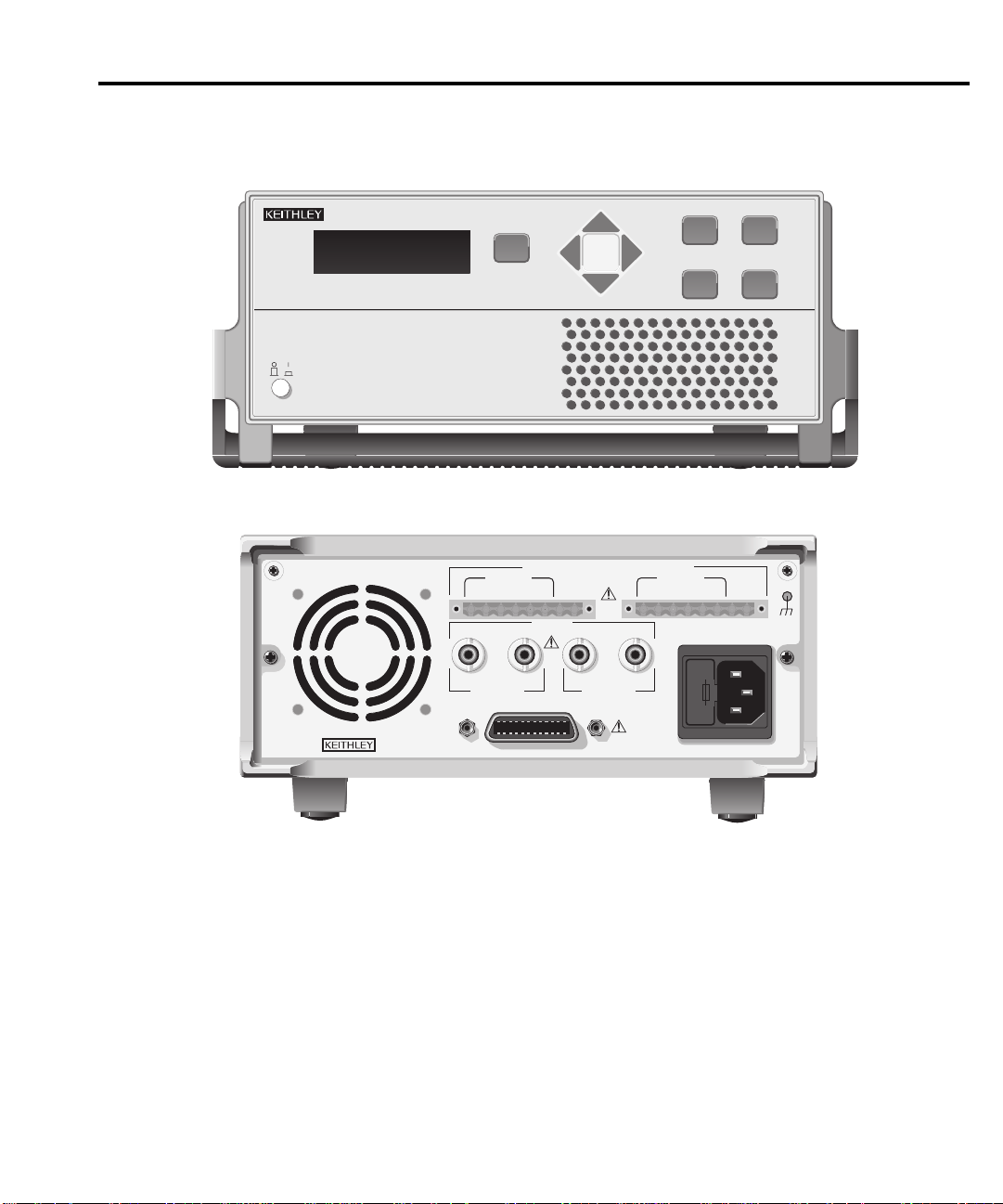
Figure 1-2
A
WARNING:NO INTERNAL OPERATOR SERVICABLE PARTS,SERVICE BY QUALIFIED PERSONNEL ONLY.
CAUTION:FOR CONTINUED PROTECTION AGAINST FIRE HAZARD,REPLACE FUSE WITH SAME TYPE AND RATING.
Model 2306-VS dual channel battery/charger simulator
Getting Started 1-5
POWER
) Front Panel
2306-VS DUAL CHANNEL BATTERY/CHARGER SIMULATOR
DISPLAY
ISOLATION FROM EARTH: 22 VOLTS MAX.
MADE IN
U.S.A.
OUTPUT #1
SOURCE SENSE SOURCE
+++
IN OUT IN OUT
CHANNEL 1 CHANNEL 2
DVM IN
____
TRIGGER
CAT I
IEEE-488
+
DVM IN
+30 VDC MAX.
OUTPUT #2
SOURCE SENSE SOURCE
+++
LINE FUSE
SLOWBLOW
2.0A, 250V
LINE RATING
100-120VAC,
200-240VAC
50, 60 HZ
165VA MAX.
LOCAL
MENU
ENTER
DVM IN
____
OPERATE
SET
+
B) Rear Panel
NOTE The output from each channel is isolated from the other channel.
Make sure that the maximum combined channel output is not exceeded (see Specifications in
Appendix A). Also, do not exceed 3A when using the power supply as a sink. For output volt
-
ages exceeding 5V, the maximum sink current is less than 3A (derate the maximum sink current
0.2A for each volt over 5V).

1-6 Getting Started
F
NOTE When using the power supply as a sink (negative polarity), the power supply is dissi-
A simplified diagram of the power supply is shown in Figure 1-3. Note that it can read back
the output voltage (V
Current Readback Range: The Model 2306 has two ranges for current readback: 5A and
5mA. On the 5A range display resolution is 100μA, and on the 5mA range resolution is 0.1μA.
The power supply also has a digital voltmeter (DVM) that is independent of the power supply
circuit. The DVM can measure up to +30V (1mV resolution).
When used with a pulsed load, the power supply can read back peak current, idle current, and
average current. See Section 3 for details. A long integration (up to 60 seconds) function is
provided to measure average current of a low frequency pulse (long period) or a series of pulses.
See Section 4 for details.
pating rather than sourcing power (see “Sink Operation” in Section 2).
) and current (I
meter
). Display resolution for voltage readback is 1mV.
meter
igure 1-3
Simplified power supply diagram
Source
Battery Channel
(Channel #1)
I meter
V-Source
with I-Limit
V meter
+
Source
_
Charger Channel
(Channel #2)
I meter
V-Source
with I-Limit
+
V meter
_
DVM
Digital
Voltmeter
+
Digital
DVM
Voltmeter
_
+
_
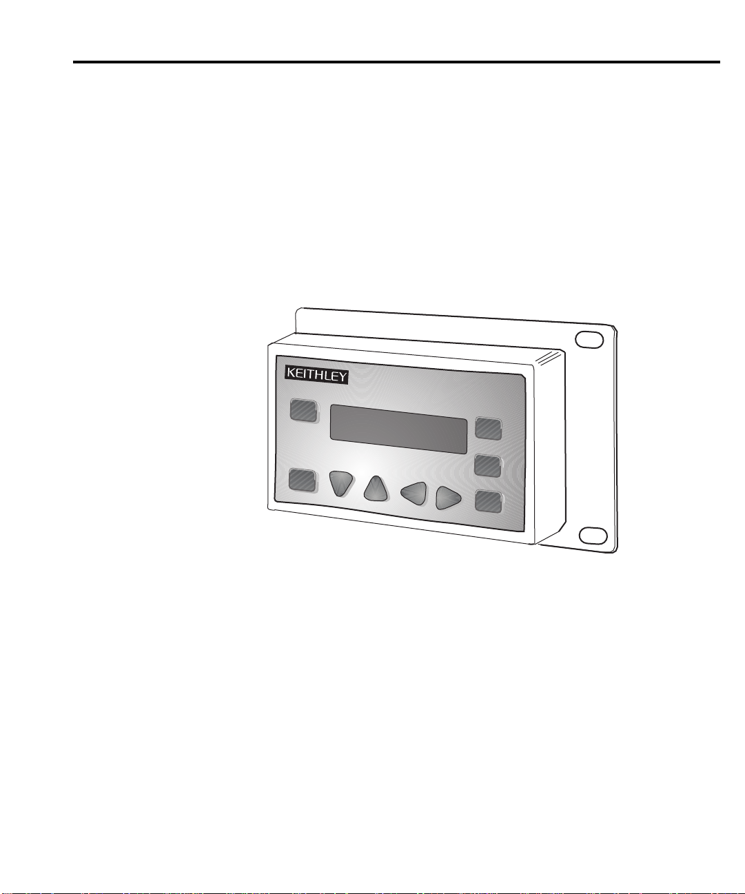
Remote display option
F
NOTE The remote display option cannot be used with the Model 2306-VS
If mounting the power supply in a location where the display cannot be seen or the controls
are not easily accessible, use the optional Model 2304-DISP or 2306-DISP Display Module (see
Figure 1-4). This remote display module includes all front panel instrument controls/features
(with the exception of power). All features/menus work as described for the Model 2306
(exceptions are noted). A 9 foot cable attaches the remote display to the rear of the power supply
allowing the unit to be operated remotely.
igure 1-4
2304-DISP Remote display
option (2306-DISP similar)
Getting Started 1-7
2304-DISP REMOTE DISPLAY
OPERATE
DISPLAY
LOCAL
MENU
SET
ENTER
NOTE When using the remote display, VFD BRIGHTNESS may not appear in the main menu
(dependent on the firmware revision in the unit).
Plug the remote display module into the rear panel connector labeled “REMOTE DISPLAY
OPTION” (see rear panel in
Figure 1-1). When plugged in, the main display module is disabled
with the following message displayed:
REMOTE PANEL
ENABLED
When the remote display module is unplugged, control returns to the main display module.
NOTE When connecting or disconnecting the remote display, allow a few seconds for the
power supply to recognize the action. Fast, repeated connects/disconnects of the
remote display may cause the power supply to hang or appear to hang. Disconnecting
the remote display and waiting a few seconds to reconnect it may clear the problem.
If not, cycling power on the power supply clears the condition.

1-8 Getting Started
Power-up
Line power connection
The power supply operates from a line voltage in the range of 100-120VAC/200-240VAC at
a frequency of 50 or 60Hz. Line voltage and frequency are automatically sensed, therefore there
are no switches to set. Check to see that the line power in your area is compatible. Use the
:SYSTem :LFRequency? query (Section 11) to read the line frequency.
Perform the following steps to connect the power supply to the line power and turn it on:
WAR NING The power cord supplied with the Model 2306 contains a separate ground for
1. Before plugging in the power cord, make sure the front panel power switch is in the off
2. Connect the female end of the supplied power cord to the AC receptacle on the rear
3. Turn on the power supply by pressing the front panel power switch to the on (1) position.
use with grounded outlets. When proper connections are made, instrument
chassis is connected to power line ground through the ground wire in the power
cord. Failure to use a grounded outlet may result in personal injury or death due
to electric shock.
(0) position.
panel.
Power-up sequence
On power-up, the power supply performs self-tests on its RAM and EPROM. After a blinking
cursor appears on line one, RAM tests are completed. After a blinking cursor appears on line
two, EPROM self tests are completed.
NOTE If a problem develops while the instrument is under warranty, return it to Keithley
Instruments Inc., for repair.
If the instrument passes the self tests, the following information is briefly displayed:
• Top line — The model number and the IEEE-488 address are displayed. (The factory
default GPIB address is 16.)
• Bottom line — Firmware revision levels are displayed for the main board and the display
board. Also displayed is the detected line frequency.
After displaying the above information, any errors that occurred during the startup sequence
will be displayed. Then, the instrument goes to the default settings or the saved power up settings
(*RST or SAV0-4) display type with the output off (
missed error messages may be viewed over the bus using the :SYST:ERR? (see “Error Queue”
in Section 7).
NOTE For Models 2306-PJ and 2306-VS, the saved power up settings available are from
SAV0-SAV2.
see “Default settings” on page 1-11). Any
 Loading...