

Page 1

www.keithley.com
Series 2268
850-Watt Programmable DC Power Supplies
Reference Manual
2268S-901-01 Rev. A / January 2015
*P2268S90101A*
2268S-901-01
A Greater Measure of Condence
A Tektr onix Company
Page 2

850 Watt DC Power Supplies
Series 2268
Reference Manual
© 2015, Keithley Instruments
Cleveland, Ohio, U.S.A.
All rights reserved.
Any unauthorized reproduction, photocopy, or use of the information herein, in whole or in part,
without the prior written approval of Keithley Instruments is strictly prohibited.
All Keithley Instruments product names are trademarks or registered trademarks of Keithley
Instruments. Other brand names are trademarks or registered trademarks of their respective holders.
Document number: 2268S-901-01 Rev. A / January 2015
Page 3

Safety Precautions
The following safety precautions should be observed before using this product and any associated instrumentation. Although
some instruments and accessories would normally be used with nonhazardous voltages, there are situations where hazardous
conditions may be present.
This product is intended for use by qualified personnel who recognize shock hazards and are familiar with the safety precautions
required to avoid possible injury. Read and follow all installation, operation, and maintenance information carefully before using
the product. Refer to the user documentation for complete product specifications.
If the product is used in a manner not specified, the protection provided by the product warranty may be impaired.
The types of product users are:
Responsible body is the individual or group responsible for the use and maintenance of equipment, for ensuring that the
equipment is operated within its specifications and operating limits, and for ensuring that operators are adequately trained.
Operators use the product for its intended function. They must be trained in electrical safety procedures and proper use of the
instrument. They must be protected from electric shock and contact with hazardous live circuits.
Maintenance personnel perform routine procedures on the product to keep it operating properly, for example, setting the line
voltage or replacing consumable materials. Maintenance procedures are described in the user documentation. The procedures
explicitly state if the operator may perform them. Otherwise, they should be performed only by service personnel.
Service personnel are trained to work on live circuits, perform safe installations, and repair products. Only properly trained
service personnel may perform installation and service procedures.
Keithley Instruments products are designed for use with electrical signals that are measurement, control, and data I/O
connections, with low transient overvoltages, and must not be directly connected to mains voltage or to voltage sources with high
transient overvoltages. Measurement Category II (as referenced in IEC 60664) connections require protection for high transient
overvoltages often associated with local AC mains connections. Certain Keithley measuring instruments may be connected to
mains. These instruments will be marked as category II or higher.
Unless explicitly allowed in the specifications, operating manual, and instrument labels, do not connect any instrument to mains.
Exercise extreme caution when a shock hazard is present. Lethal voltage may be present on cable connector jacks or test
fixtures. The American National Standards Institute (ANSI) states that a shock hazard exists when voltage levels greater than
30 V RMS, 42.4 V peak, or 60 VDC are present. A good safety practice is to expect that hazardous voltage is present in any
unknown circuit before measuring.
Operators of this product must be protected from electric shock at all times. The responsible body must ensure that operators are
prevented access and/or insulated from every connection point. In some cases, connections must be exposed to potential
human contact. Product operators in these circumstances must be trained to protect themselves from the risk of electric shock. If
the circuit is capable of operating at or above 1000 V, no conductive part of the circuit may be exposed.
Do not connect switching cards directly to unlimited power circuits. They are intended to be used with impedance-limited
sources. NEVER connect switching cards directly to AC mains. When connecting sources to switching cards, install protective
devices to limit fault current and voltage to the card.
Before operating an instrument, ensure that the line cord is connected to a properly-grounded power receptacle. Inspect the
connecting cables, test leads, and jumpers for possible wear, cracks, or breaks before each use.
When installing equipment where access to the main power cord is restricted, such as rack mounting, a separate main input
power disconnect device must be provided in close proximity to the equipment and within easy reach of the operator.
For maximum safety, do not touch the product, test cables, or any other instruments while power is applied to the circuit under
test. ALWAYS remove power from the entire test system and discharge any capacitors before: connecting or disconnecting
cables or jumpers, installing or removing switching cards, or making internal changes, such as installing or removing jumpers.
Do not touch any object that could provide a current path to the common side of the circuit under test or power line (earth)
ground. Always make measurements with dry hands while standing on a dry, insulated surface capable of withstanding the
voltage being measured.
2268S-901-01 Rev. A / January 2015 i
Page 4

For safety, instruments and accessories must be used in accordance with the operating instructions. If the instruments or
accessories are used in a manner not specified in the operating instructions, the protection provided by the equipment may be
impaired.
Do not exceed the maximum signal levels of the instruments and accessories, as defined in the specifications and operating
information, and as shown on the instrument or test fixture panels, or switching card.
When fuses are used in a product, replace with the same type and rating for continued protection against fire hazard.
Chassis connections must only be used as shield connections for measuring circuits, NOT as protective earth (safety ground)
connections.
If you are using a test fixture, keep the lid closed while power is applied to the device under test. Safe operation requires the use
of a lid interlock.
screw is present, connect it to protective earth (safety ground) using the wire recommended in the user documentation.
If a
The
user documentation in all cases where the symbol is marked on the instrument.
The
contact with these voltages.
The symbol on an instrument shows that the surface may be hot. Avoid personal contact to prevent burns.
The
If this
properly disposed of according to federal, state, and local laws.
The WARNING heading in the user documentation explains dangers that might result in personal injury or death. Always read
the associated information very carefully before performing the indicated procedure.
The CAUTION heading in the user documentation explains hazards that could damage the instrument. Such damage may
invalidate the warranty.
Instrumentation and accessories shall not be connected to humans.
Before performing any maintenance, disconnect the line cord and all test cables.
To maintain protection from electric shock and fire, replacement components in mains circuits — including the power
transformer, test leads, and input jacks — must be purchased from Keithley Instruments. Standard fuses with applicable national
safety approvals may be used if the rating and type are the same. Other components that are not safety-related may be
purchased from other suppliers as long as they are equivalent to the original component (note that selected parts should be
purchased only through Keithley Instruments to maintain accuracy and functionality of the product). If you are unsure about the
applicability of a replacement component, call a Keithley Instruments office for information.
symbol on an instrument means caution, risk of danger. The user must refer to the operating instructions located in the
symbol on an instrument means caution, risk of electric shock. Use standard safety precautions to avoid personal
symbol indicates a connection terminal to the equipment frame.
symbol is on a product, it indicates that mercury is present in the display lamp. Please note that the lamp must be
To clean an instrument, use a damp cloth or mild, water-based cleaner. Clean the exterior of the instrument only. Do not apply
cleaner directly to the instrument or allow liquids to enter or spill on the instrument. Products that consist of a circuit board with no
case or chassis (e.g., a data acquisition board for installation into a computer) should never require cleaning if handled according
to instructions. If the board becomes contaminated and operation is affected, the board should be returned to the factory for
proper cleaning/servicing.
Safety precaution revision as of January 2013.
ii 2268S-901-01 Rev. A / January 2015
Page 5

Table of Contents
INTRODUCTION ...................................................................................................................... 11
ELCOME ........................................................................................................................... 11
W
XTENDED WARRANTY ........................................................................................................ 11
E
C
ONTACT INFORMATION ....................................................................................................... 11
EATURES AND OPTIONS ..................................................................................................... 12
F
U
NPACKING AND INSPECTING ............................................................................................... 12
Inspect for Damage ...................................................................................................................... 12
Shipment Contents ....................................................................................................................... 12
S
ERIES 2268 850-WATT MODELS ........................................................................................ 13
ACK MOUNT KIT OPTIONS .................................................................................................. 13
R
F
RONT PANEL FAMILIARIZATION ........................................................................................... 13
R
EAR PANEL FAMILIARIZATION ............................................................................................. 15
INSTALLATION ....................................................................................................................... 17
B
ASIC SETUP PROCEDURE ................................................................................................... 17
TEP 1: INSPECTING AND CLEANING ..................................................................................... 18
S
Initial Inspection............................................................................................................................ 18
Periodic Cleaning ......................................................................................................................... 18
S
TEP 2: LOCATION AND MOUNTING ....................................................................................... 19
Rack Mounting ............................................................................................................................. 19
Ventilation ..................................................................................................................................... 19
S
TEP 3: CONNECTING AC INPUT POWER .............................................................................. 20
AC Input Connector ...................................................................................................................... 20
S
TEP 4: SELECTING LOAD WIRES ......................................................................................... 21
Load Wiring .................................................................................................................................. 21
Insulation Rating........................................................................................................................... 21
Current Carrying Capacity ............................................................................................................ 21
Maximum Load Wiring Length For Operation With Sense Lines ................................................. 22
Noise and Impedance Effects ...................................................................................................... 22
S
TEP 5: PERFORMING FUNCTIONAL TESTS ............................................................................ 23
Powering the Power Supply On/Off ............................................................................................. 23
Voltage and Current Mode Operation Checks ............................................................................. 24
S
TEP 6: CONNECTING LOADS ............................................................................................... 25
DC Output Connectors ................................................................................................................. 25
20 V-40 V Models ......................................................................................................................... 25
60 V-150 V Models ....................................................................................................................... 25
Inductive Loads and Batteries ...................................................................................................... 26
Connecting Single Loads ............................................................................................................. 27
Connecting Multiple Loads ........................................................................................................... 27
S
TEP 7: CONNECTING REMOTE SENSING .............................................................................. 28
2268S-901-01 Rev. A / January 2015 iii
Page 6

Table of Contents Series 2268 850 Watt DC Power Supplies Reference Manual
LOCAL OPERATION ............................................................................................................... 30
NTRODUCTION .................................................................................................................... 30
I
C
ONFIGURING SETTINGS FROM THE FRONT PANEL ................................................................ 30
Using the Rotary Adjust/Enter Control ......................................................................................... 30
Coarse and Fine Adjustment Modes ............................................................................................ 31
N
AVIGATING THE MENU SYSTEM ........................................................................................... 32
Setting VOLTS and AMPS Modes ............................................................................................... 32
Normal Display Mode and Inactivity Timeout ............................................................................... 33
D
ISPLAY MESSAGES ON THE FRONT PANEL ........................................................................... 35
S
TANDARD (LOCAL) OPERATION ........................................................................................... 37
O
PERATING MODES ............................................................................................................. 37
Constant Voltage (CV) Mode Operation ...................................................................................... 37
Constant Current (CC) Mode Operation ...................................................................................... 38
Constant Power (CP) Mode Operation ........................................................................................ 38
Automatic Mode Crossover .......................................................................................................... 38
S
HIPPED CONFIGURATION (LOCAL OPERATION) .................................................................... 41
NABLING THE OUTPUT ........................................................................................................ 41
E
E
NABLING THE AUXILIARY OUTPUT ....................................................................................... 42
O
UTPUT AUTO START MODE (AUTO RESTART) ...................................................................... 42
UXILIARY AUTO START MODE ............................................................................................. 43
A
C
ONSTANT POWER MODE .................................................................................................... 43
LARMS AND ERRORS.......................................................................................................... 44
A
C
LEARING ALARMS .............................................................................................................. 45
Clearing Triggered and Manual Alarms ....................................................................................... 45
Clearing a Flash Failure Alarm ..................................................................................................... 45
Clearing Automatic Alarms ........................................................................................................... 46
Front Panel Alarm LED ................................................................................................................ 46
Alarm Masking .............................................................................................................................. 47
Alarm Output Latching ................................................................................................................. 48
S
ETTING FOLDBACK MODE ................................................................................................... 49
ESETTING ACTIVATED FOLDBACK PROTECTION ................................................................... 50
R
U
SING OVER VOLTAGE PROTECTION (OVP) .......................................................................... 50
Defining the OVP Set Point .......................................................................................................... 50
U
SING UNDER VOLTAGE PROTECTION (UVP) ........................................................................ 51
Defining the UVP Set Point .......................................................................................................... 51
O
VER CURRENT PROTECTION (OCP) ................................................................................... 51
U
SING OVER TEMPERATURE PROTECTION LOCK (OTP) ......................................................... 52
Defining the OTP Mode ................................................................................................................ 52
Resetting in Latch Mode .............................................................................................................. 52
U
SING THE EXTERNAL SHUTDOWN FUNCTION ....................................................................... 53
Activating the External Shutdown Function ................................................................................. 53
Controlling the External Shutdown Function ................................................................................ 53
Defining the Polarity of the External Shutdown Signal................................................................. 54
iv 2268S-901-01 Rev. A / January 2015
Page 7

Series 2268
of Contents
850 Watt DC Power Supplies Reference Manual Table
LOOP PROTECTION .............................................................................................................. 54
Setting up Loop Protection ........................................................................................................... 54
I
NTERLOCK FUNCTION.......................................................................................................... 56
Defining the Interlock Mode ......................................................................................................... 56
O
UTPUT PROTECTION .......................................................................................................... 56
Programming Voltage Output Preset ........................................................................................... 56
Programming Current Output Preset ........................................................................................... 57
P
OWER ON STATUS SIGNAL ................................................................................................. 57
H
ARDWARE MALFUNCTION ALARMS ...................................................................................... 58
C
URRENT CONFIGURATION MEMORY SETTINGS .................................................................... 58
SER SETTING MEMORY LOCATIONS .................................................................................... 59
U
Saving User Setting Memory Locations ....................................................................................... 59
Recalling User Setting Memory Locations ................................................................................... 60
L
OCAL LOCKOUT ................................................................................................................. 61
Enabling Local Lockout ................................................................................................................ 61
Disabling Local Lockout ............................................................................................................... 61
R
ESETTING THE POWER SUPPLY .......................................................................................... 62
U
SING MULTIPLE POWER SUPPLIES ...................................................................................... 63
ONFIGURING MULTIPLE SUPPLIES FOR SERIES OPERATION .................................................. 64
C
Load Considerations .................................................................................................................... 64
Connecting to the Load in Local Sensing Mode .......................................................................... 65
Connecting to the Load in Remote Sensing Mode ...................................................................... 66
C
ONFIGURING MULTIPLE SUPPLIES FOR CURRENT SHARING OPERATION (APG METHOD) ....... 67
Setting up the Controller Unit ....................................................................................................... 67
Setting up the Slave Units ............................................................................................................ 68
Setting Over Voltage Protection (OVP) ........................................................................................ 68
Setting Foldback Protection ......................................................................................................... 69
C
ONNECTING TO THE LOAD IN LOCAL SENSING MODE (PARALLEL CONTROL METHOD) ............ 69
ONNECTING TO THE LOAD IN REMOTE SENSING MODE (PARALLEL CONTROL METHOD) ......... 70
C
P
OWER SAVING CONTROL (SLEEP MODE) ............................................................................. 70
ANALOG PROGRAMMING & ISOLATED ANALOG PROGRAMMING .................................. 72
NTRODUCTION .................................................................................................................... 72
I
A
NALOG PROGRAMMING (APG) OF OUTPUT VOLTAGE AND OUTPUT CURRENT ....................... 72
EMOTE PROGRAMMING OPTIONS........................................................................................ 73
R
Analog Monitor Signals ................................................................................................................ 73
Auxiliary Outputs .......................................................................................................................... 73
Analog Programming (APG) Connector J1 .................................................................................. 74
Making Control Connections ........................................................................................................ 75
Wiring ........................................................................................................................................... 76
A
NALOG PROGRAMMING MODE ............................................................................................ 76
Analog Programming With External Voltage Source ................................................................... 76
Voltage-Controlled Voltage APG Setup ....................................................................................... 77
2268S-901-01 Rev. A / January 2015 v
Page 8

Table of Contents Series 2268 850 Watt DC Power Supplies Reference Manual
Voltage-Controlled Current APG Setup ....................................................................................... 79
A
NALOG PROGRAMMING WITH EXTERNAL RESISTOR.............................................................. 81
Resistive-Controlled Voltage APG Setup ..................................................................................... 82
Resistive-Controlled Current APG Setup ..................................................................................... 84
V
OLTAGE AND CURRENT READBACK ..................................................................................... 86
I
SOLATED ANALOG PROGRAMMING MODE (ISOL) .................................................................. 87
AUX Output and Isolated Analog Programming (ISOL) Connector ............................................. 87
Making ISOL Control Connections ............................................................................................... 89
ISOL Programming With External Voltage Source ...................................................................... 89
Voltage-Controlled Voltage ISOL Setup ...................................................................................... 90
Voltage-Controlled Current ISOL Setup ....................................................................................... 92
A
NALOG PROGRAMMING WITH EXTERNAL RESISTOR.............................................................. 94
Resistive-Controlled Voltage ISOL Setup .................................................................................... 95
Resistive-Controlled Current ISOL Setup .................................................................................... 97
V
OLTAGE AND CURRENT READBACK (ISOLATED) ................................................................... 99
Q
UERY REMOTE CONTROL SOURCE STATE .......................................................................... 99
REMOTE OPERATION .......................................................................................................... 101
I
NTRODUCTION .................................................................................................................. 101
ARDWARE AND CONNECTION SETUP ................................................................................. 101
H
C
ONFIGURING REMOTE CONTROL USING RS-232 ............................................................... 102
RS-232 Communication Cable with RJ-45 to DB-9 ................................................................... 103
RS-232 Communication Cable with RJ-45 to DB-25 ................................................................. 104
C
ONFIGURING REMOTE CONTROL USING RS-485 ............................................................... 106
RS-485 Communication Cable with RJ-45 to DB-9 ................................................................... 106
RS-485 Communication Cable with Two RJ-45s ....................................................................... 107
C
ONFIGURING REMOTE CONTROL USING USB .................................................................... 108
Setting Up the PC to Use the USB Connection ......................................................................... 108
C
ONFIGURING REMOTE CONROL USING GPIB .................................................................... 114
GPIB Pin Description ................................................................................................................. 114
Communication with Your Device .............................................................................................. 115
Selecting a Communication Port ................................................................................................ 115
C
ONFIGURING REMOTE CONTROL USING ETHERNET/LAN (ENET) ....................................... 117
ULTIPLE POWER SUPPLY CONNECTIONS TO RS-485 BUS .................................................. 118
M
Multiple Power Supply Setup ..................................................................................................... 118
T
ERMINAL CONFIGURATION ................................................................................................ 119
Data Format ............................................................................................................................... 119
End of Message ......................................................................................................................... 119
HyperTerminal ............................................................................................................................ 119
S
ELECTING THE APPROPRIATE COMMUNICATION PORT ........................................................ 122
Data Rate Setting (Kbps) ........................................................................................................... 122
Multichannel Address Setting ..................................................................................................... 123
Remote Interface Addressing ..................................................................................................... 123
vi 2268S-901-01 Rev. A / January 2015
Page 9

Series 2268
of Contents
850 Watt DC Power Supplies Reference Manual Table
Multichannel Commands Explained ........................................................................................... 124
S
TATUS REPORTING IN SCPI ............................................................................................. 125
S
TATUS REGISTERS MODEL FROM IEEE 488.2 ................................................................... 127
Status Byte ................................................................................................................................. 128
Error/Event Queue (ERR) .......................................................................................................... 128
Questionable Status Register Summary (QSR) ......................................................................... 128
Message Available (MAV) .......................................................................................................... 129
Standard Event Status Summary (ESB) .................................................................................... 129
Master Summary Status (MSS) ................................................................................................. 129
Request Service (RQS) .............................................................................................................. 129
Operation Status Register Summary (OSR) .............................................................................. 130
Standard Event Status Register (SESR) ................................................................................... 131
S
TANDARD SCPI REGISTER STRUCTURE ............................................................................ 134
OPER
ATION STATUS REGISTER ......................................................................................... 135
Current Share Sub-Register ....................................................................................................... 137
Operation Status Register Commands ...................................................................................... 138
Current Sharing Sub-Register Commands ................................................................................ 139
Shutdown Sub-Register Commands .......................................................................................... 140
Protection Sub-Register Commands.......................................................................................... 141
QUES
TIONABLE STATUS REGISTER ................................................................................... 142
VOLTage Sub-Register .............................................................................................................. 144
TEMPerature Sub-Register ........................................................................................................ 144
Questionable Status Register Commands ................................................................................. 145
Voltage Status Register Commands .......................................................................................... 146
Temperature Status Register Commands ................................................................................. 147
SCPI
ERROR/EVENT QUEUE .............................................................................................. 148
R
ESET COMMAND .............................................................................................................. 150
C
LEAR ALL STATUS REGISTERS ......................................................................................... 151
Clear Status Command .............................................................................................................. 151
SCPI Preset Status .................................................................................................................... 151
C
OMMAND LINE HELP SYSTEM ........................................................................................... 152
Querying Help for all Command Headers .................................................................................. 152
Querying Help for Legacy Command Headers .......................................................................... 153
L
OCKING AND UNLOCKING THE FRONT PANEL ..................................................................... 154
UTO SEQUENCE PROGRAMMING ....................................................................................... 154
A
C
ONFIGURE OTHER PROTECTION MECHANISMS .................................................................. 160
Foldback Protection ................................................................................................................... 160
Over Temperature Protection ..................................................................................................... 161
Loop Protection Enable/Disable ................................................................................................. 161
Interlock Enable/Disable ............................................................................................................ 161
S
AVE AND RECALL ............................................................................................................. 162
S
ET ANALOG PROGRAMMING LEVEL ................................................................................... 162
ET REMOTE PROGRAMMING INTERFACE ............................................................................ 162
S
2268S-901-01 Rev. A / January 2015 vii
Page 10

Table of Contents Series 2268 850 Watt DC Power Supplies Reference Manual
PROTECTION MASK (ENABLE ALARMS) ............................................................................... 163
LAN/ETHERNET SETUP AND COMMUNICATION ............................................................... 164
NTRODUCTION .................................................................................................................. 164
I
S
ETTING UP LAN/ETHERNET .............................................................................................. 164
ASICS ............................................................................................................................. 164
B
Communication Cable Requirements ........................................................................................ 164
ENET Connector ........................................................................................................................ 165
ENET Connector LEDs .............................................................................................................. 166
L
OCAL AREA NETWORK (LAN) ........................................................................................... 166
Media Access Control (MAC) Address....................................................................................... 166
Communication Configuration .................................................................................................... 166
LAN Connection ......................................................................................................................... 167
Direct-to-PC Connection ............................................................................................................ 167
Private Network Connection ....................................................................................................... 167
C
ONNECTING TO A NETWORK ............................................................................................. 169
Connecting with PC on Same Side of Router as Power Supply ................................................ 169
Connecting with Power Supply Hidden Behind a Router ........................................................... 170
Socket Port Number ................................................................................................................... 172
Instrument Drivers and Application Software ............................................................................. 173
LXI
DISCOVERY BROWSER SOFTWARE ............................................................................... 173
S
ETTING LAN PARAMETERS ............................................................................................... 173
Setting LAN Parameters via Serial or USB Port ........................................................................ 173
Setting LAN Parameters via Web Interface ............................................................................... 173
S
ETTING A STATIC IP ADDRESS THROUGH ETHERNET, USB, AND SERIAL INTERFACES .......... 176
Ethernet ...................................................................................................................................... 176
USB ............................................................................................................................................ 177
RS232 (SERIAL) ........................................................................................................................ 184
SYSTEM
COMMANDS .................................................................................................... 190
Subsystem Syntax...................................................................................................................... 190
CALIBRATION AND TROUBLESHOOTING ......................................................................... 193
NTRODUCTION .................................................................................................................. 193
I
M
AIN VOLTAGE AND CURRENT CALIBRATION PRINCIPLE ...................................................... 194
Understanding the Problem ....................................................................................................... 194
Step 1: Gain Calibration ............................................................................................................. 195
Step 2: Offset Calibration ........................................................................................................... 195
Step 3: Recalibrate Gain ............................................................................................................ 196
S
TORING CALIBRATION DATA ............................................................................................. 196
C
ALIBRATING THE OUTPUT VOLTAGE .................................................................................. 197
Gain Calibration.......................................................................................................................... 197
Offset Calibration........................................................................................................................ 197
C
ALIBRATING THE OUTPUT CURRENT.................................................................................. 198
Gain Calibration.......................................................................................................................... 198
viii 2268S-901-01 Rev. A / January 2015
Page 11

Series 2268
of Contents
850 Watt DC Power Supplies Reference Manual Table
Offset Calibration........................................................................................................................ 198
O
VER VOLTAGE PROTECTION CALIBRATION ........................................................................ 199
N
ON-ISOLATED ANALOG PROGRAMMING CALIBRATION ......................................................... 200
Non-isolated Voltage Monitoring Calibration .............................................................................. 200
Non-isolated Current Monitoring Calibration .............................................................................. 201
Non-isolated Voltage Programming of Voltage Calibration ....................................................... 202
Non-isolated Resistive Programming of Voltage Calibration ..................................................... 203
Non-isolated Voltage Programming of Current Calibration ........................................................ 204
Non-isolated Resistive Programming of Current Calibration ..................................................... 205
C
ALIBRATION PROCEDURE FOR ISOLATED MODES ............................................................... 206
Isolated Voltage Monitoring Calibration ..................................................................................... 206
Isolated Current Monitoring Calibration ..................................................................................... 207
Isolated Voltage Programming of Voltage Calibration ............................................................... 208
Isolated Resistive Programming of Voltage Calibration ............................................................. 209
Isolated Voltage Programming of Current Calibration ............................................................... 210
Isolated Resistive Programming of Current Calibration ............................................................. 211
APG
CALIBRATION ............................................................................................................ 212
Calibrating the Input Voltage APG Signal .................................................................................. 212
Calibrating the Input Current APG Signal .................................................................................. 213
R
ESTORE FACTORY CALIBRATION ...................................................................................... 214
R
ESTORE DEFAULT CALIBRATION ....................................................................................... 214
SER DIAGNOSTICS ........................................................................................................... 214
U
E
MERGENCY SHUTDOWN ................................................................................................... 215
NUSUAL OR ERRATIC OPERATION ..................................................................................... 215
U
T
ROUBLESHOOTING FOR OPERATORS ................................................................................. 215
SCPI COMMAND REFERENCE ............................................................................................ 216
CONFORMANCE INFORMATION ................................................................................... 216
SCPI
Codes and Standards ................................................................................................................ 216
IEEE 488.2/SCPI Syntax and Style............................................................................................ 217
SCPI Command Hierarchy ......................................................................................................... 217
Using SCPI Commands ............................................................................................................. 218
Parameter Types ........................................................................................................................ 221
SCPI
COMMAND TREE ....................................................................................................... 222
COMMAND SUMMARY ................................................................................................ 228
SCPI
IEEE 488.2 Commands .............................................................................................................. 228
Readback Commands ................................................................................................................ 230
SCPI Commands for Output Control .......................................................................................... 231
SCPI Commands for Calibration ................................................................................................ 232
SCPI Commands to Clear All Protection Mechanisms .............................................................. 234
SCPI Commands for Foldback Protection ................................................................................. 234
SCPI Commands for Power ....................................................................................................... 234
SCPI Commands for Triggering ................................................................................................. 235
System Commands .................................................................................................................... 235
2268S-901-01 Rev. A / January 2015 ix
Page 12

Table of Contents Series 2268 850 Watt DC Power Supplies Reference Manual
Status Commands ...................................................................................................................... 237
Protection Commands ................................................................................................................ 242
Auto Sequence Commands ....................................................................................................... 242
ERROR MESSAGES.............................................................................................................. 243
RROR MESSAGES ............................................................................................................ 243
E
Command Error List ................................................................................................................... 244
Execution Error List .................................................................................................................... 245
Device-Specific Error List ........................................................................................................... 246
Query Error List .......................................................................................................................... 246
SPECIFICATIONS .................................................................................................................. 247
PECIFICATIONS ................................................................................................................ 247
S
Output Performance Specifications............................................................................................ 247
Environmental Specifications (Indoor use) ................................................................................ 248
Mechanical Specifications .......................................................................................................... 248
Regulatory Approvals ................................................................................................................. 248
M
ECHANICAL DIMENSIONS ................................................................................................. 249
x 2268S-901-01 Rev. A / January 2015
Page 13

Supply.
In this section:
WELCOME
Section 1
Introduction
This section describes the features of the 2268 Series 850 Watt Power
Thank you for choosing a Keithley Instruments product. The Series 2268 850-Watt DC
power supply is designed for use in the laboratory and for test applications. It also has
excellent regulation and low output voltage ripple. The digital displays provide accurate
readings of voltage and current and also provide for easy, precise setting of output values
using digital entry of current and voltage values. Output voltage can be set from the front
panel, using a remote analog voltage or resistance, or over any of the digital interfa ces: LAN,
USB, GPIB, or RS-485. Voltage and current analog outputs are also available for remote
monitoring and analog control.
EXTENDED WARRANTY
Additional years of warranty coverage are available on many products. These valuable
contracts protect you from unbudgeted service expenses and provide additional years of
protection at a fraction of th e price o f a repa ir. Exte nded w arranties are av ailable o n new and
existing products. Contact your local Keithley Instruments representative for details.
CONTACT INFORMATION
If you have any questions after you review the information in this documentation, please
contact your local Keithley Instruments office, sales partner, or distributor, or call Ke ithley
Instruments corporate headquarters (toll-free inside the U.S. and Canada only) at
1-800-935-5595, or from outside the U.S. at +1-440-248-0400. For worldwide contact
numbers, visit the Keithley Instruments website (http://www.keithley.com).
2268S-901-01 Rev. A / January 2015 11
Page 14

Introduction Series 2268 850 Watt DC Power Supplies Reference Manual
FEATURES AND OPTIONS
The Series 2268 Programmable DC Power Supply provides stable, variable output voltage
and current for a broad range of development and system requirements. The power supplies
have a high power density, numerous indus try standard interfaces, and a num ber of excellent
features:
• RS-232, RS-485, GPIB, Ethernet (ENET), analog programming (APG), and USB
built-in ports
• Seamless switching between front panel and any digital interface (RS-232, RS-485,
USB, GPIB or ENET)
• Simultaneous digital displays for both voltage and current
• Front panel control by rotary Adjust/Enter knob, permitting high resolution output
setting
• Active Power Factor Correction (PFC) reduces input current and input current harmonics
• Automatic crossover system allowing the power supply to switch between Constant
Current, Constant Voltage and Constant Power operating modes
• Parallel or series connection among multiple units to produce greater diversity or to use
in higher power applications
• Short-circuit protection of DC outputs, providing greater operating safety
• Built-in APG and ISOL interface to provide a galvanically isolated analog voltage
control of the output, master/slave output tracking, and remote Enable/Disable for safety
and precision
• Remote output voltage sensing to automatically compensate for cable losses.
• Software calibrated
• Three user setting memory locations
UNPACKING AND INSPECTING
Inspect for Damage
Upon receiving the Model 2268, careful ly unpack the unit, and inspec t for any obvious signs
of physical damage that might have occurred during shipment. Notify the shipping agent of
any damage immediately.
Shipment Contents
The following items are included with every Series 2268 order:
• Series 2268 power supply
• Series 2268 product information CD-ROM
• AC line power cord
• Series 2268 additional accessories, as ordered
12 2268S-901-01 Rev. A / January 2015
Page 15

Series 2268 850 Watt DC Power Supplies Reference Manual Introduction
Model
Output Voltage
Output Current
2268-20-42
0-20 V
0-42 A
2268-40-21
0-40 V
0-21 A
2268-60-14
0-60 V
0-14 A
2268-80-10.5
0-80 V
0-10.5 A
2268-100-8.5
0-100 V
0-8.5 A
2268-150-5.6
0-150 V
0-5.6 A
Important: We recommend that you provide additional rear support to the
Series 2268 when mounting it in a rack.
Number of Units
Model Number
Item
Description
1
Front panel power switch
2
Front panel display see Figure 2
3
Air intake vents
SERIES 2268 850-WATT MODELS
RACK MOUNT KIT OPTIONS
Rack-mount kits are available for the Series 2268 instruments. The table below shows the
available models. Complete details and installa tion instructions are in cluded in the docum ent
that ships with each rack-mount kit.
Single 2268-RMK-1
Dual 2268-RMK-2
FRONT PANEL FAMILIARIZATION
Figure 1: Series 2268 850-Watt Front Panel
2268S-901-01 Rev. A / January 2015 13
Page 16

Introduction Series 2268 850 Watt DC Power Supplies Reference Manual
Item
Description
1
Rotary Adjust/Enter control
2
Constant Voltage (CV) Mode LED (green)
3
Constant Current (CC) Mode LED (green)
4
Output Current Display
5
Model Identification Label
6
Output Voltage Display
7
Alarm Indicator LED (red)
8
OUTPUT ENABLE Main button
9
OUTPUT ENABLE Aux button
10
9-Position Mode Control (For detailed information, see
Figure 2: Series 2268 850-Watt Front Panel Display and Controls
“Configuring Settings from the Front Panel” on page 30).
14 2268S-901-01 Rev. A / January 2015
Page 17

Series 2268 850 Watt DC Power Supplies Reference Manual Introduction
REAR PANEL FAMILIARIZATION
Figure 3: Series 2268 850-Watt, 20 V to 40 V Rear Panel
Figure 4: Series 2268 850-Watt, 60 V to 150 V Rear Panel
2268S-901-01 Rev. A / January 2015 15
Page 18

Introduction Series 2268 850 Watt DC Power Supplies Reference Manual
Item
Description
1
20 V– 40 V Models: DC Output Terminal Positive (6.5 mm hole diameter)
60 V–150 V Models: DC Output Connectors Positive
2
20 V– 40 V Models: DC Output Terminal Negative (6.5 mm hole diameter)
60 V–150 V Models: DC Output Connectors Negative
3 (J2)
Ethernet (ENET) or GPIB Connector
4 (J4)
RS-232/RS-485 Connector In Port
5
AC Input Connector (IEC Type)
6
Chassis Ground Stud
7 (J1)
Analog Programming (APG) Connector. For pin information, see page 74.
8 (J3)
AUX Output and Isolated Analog Programming (ISOL) Connector. For pin
information, see page 87.
9 (J5)
USB Connector
10 (J6)
RS-485 Connector Multichannel Port
11
Ethernet/LAN Connector
12
Fan Exhaust Vents
16 2268S-901-01 Rev. A / January 2015
Page 19

1
Inspect
Inspect the power supply.
“Step 1: Inspecting and
2
Install
Install the power supply
“Step 2: Location and Mounting”
3
Connect Input
Connect AC input power.
“Step 3: Connecting AC
4
Select Wires
Select wires that are
“Step 4: Selecting Load Wires”
5
Test
Perform functional tests for
“Step 5: Performing
6
Connect Loads
Connect the load wires to
“Step 6: Connecting Loads”
7
Connect
Connect remote sensing
“Step 7: Connecting
In this section:
This section provides information and procedures for inspecting, installing, and testing the
power supply.
BASIC SETUP PROCEDURE
Below is a summary of the basic setup procedure with references to the relevant sections in
this section. Refer to this table if you are unfamiliar with the installat ion requirements for the
power supply. Complete each step in the sequence give
Section 2
Installation
n.
Step Description Action Reference
Cleaning” on page 18.
(benchtop or rack mount).
Ensure adequate
ventilation.
Power
correctly rated for the
maximum DC output
current.
voltage mode operation,
current mode operation, and
front panel controls.
the DC output.
Remote
Sensing (if
required)
connectors on power supply
to load.
on page 19.
Input Power” on page 20.
on page 21.
Functional Tests” on page
23.
on page 25.
Remote Sensing” on page
28.
2268S-901-01 Rev. A / January 2015 17
Page 20

Installation Series 2268 850 Watt DC Power Supplies Reference Manual
STEP 1: INSPECTING AND CLEANING
Initial Inspection
When you first receive your unit, perform a physical check:
1. Inspect the unit for any scratches and cracks, broken switches, connectors or
displays.
2. Ensure that the packing box contains a power cord.
3. If you see external damage or suspect internal damage, contact the carrier
immediately.
Periodic Cleaning
The power supply only requires periodic cleaning, not routine servicing. Whenever a unit is
removed from operation, clean the metal surfaces with naphtha or an equivalent solvent, and
clean the front panel with a weak solution of soap and water. Use low-pressure compressed
air to blow dust from components on the printed circuit boards.
18 2268S-901-01 Rev. A / January 2015
Page 21

Series 2268 850 Watt DC Power Supplies Reference Manual Installation
STEP 2: LOCATION AND MOUNTING
The power supply may be rack-mounted or used in benchtop applications.
Rack Mounting
Keithley offers a Single and a Dual Rack Kit (2268-RMK-1 and 2268-RMK-2). See "Rack
Mount Kit Options" on page 13 for information about available rack mount kits. To purchase
a rack mount kit, contact your local Keithley Instruments off ice, sales partner, or distributor,
or call Keithley Instruments corporate headquarters (toll-free inside the U.S. and Canada
only) at 1-800-935-5595, or from outside the U.S. at +1-440-248-0400. For worldwide
contact numbers, visit the Keithley Instruments website (http://www.keithley.com).
Ventilation
Whether operating the pow er supply in a ra ck or on a bench, allow ai r to re ach the ventilatio n
inlets on the front and rear of the unit for cooling. The direction of airflow is from the front of
the unit to the back of the unit. Ventilat ion space is not required at the top, bottom or sides of
the power supply.
2268S-901-01 Rev. A / January 2015 19
Page 22

Installation Series 2268 850 Watt DC Power Supplies Reference Manual
The AC input cord is the disconn ect device f or the power su pply . The plug must
STEP 3: CONNECTING AC INPUT POWER
WARNING: Shock hazard
Disconnect AC power from the unit before re moving the cover. E ven with the
front panel power switch in the Off position, live line voltages are exposed when
the cover is removed. Repairs must be made by an Authorized Service Center.
WARNING: Shock hazard
There is a potential shock hazard if the power supply chassis and cover are not
connected to an electrical ground via the safety ground in the AC input
connector. Ensure that the power supply is connected to a grounded AC outlet
with the recommended AC input cord configured for the available line voltage
as described in this section.
WARNING: Shock hazard
be a non-locking plug which is readily identifiable by and accessible to the
operator. The input cord must be no longer than 9.84 feet (3 m).
AC Input Connector
The AC input connector is a standard IEC 16 A 250 V male connector located on the rear
panel of the power supply. The AC input cord provided is rated for 30 A, 300 V.
20 2268S-901-01 Rev. A / January 2015
Page 23

Series 2268 850 Watt DC Power Supplies Reference Manual Installation
Wire Size
(AWG)
Maximum
Current (Amps)
Wire Size
(AWG)
Maximum
Current (Amps)
20
2.5 6 61
18 4 4
97
16 6 2
155
14
10 1 192
12
16
1/0
247
10
21
2/0
303 8 36
n/a
n/a
STEP 4: SELECTING LOAD WIRES
This section provides recommendations for selecting minimum load wire sizes.
Load Wiring
To select the wiring for connecting the load to the power supply, consider the following
factors:
• Insulation rating of the wire. Current carrying capacity of the wire.
• Maximum load wiring length for operation with remote sense lines.
• Electrical noise and impedance effects of the load lines.
Insulation Rating
Use load wiring with a minim um insulation rating equiv alent to the m aximum output voltage
of the power supply.
Current Carrying Capaci ty
The load wiring must have a current carrying capacity greater than the output rating of the
power supply to ensure that the load wiring will not be damaged if the load is shorted. The
table that follo ws shows the maxim um current ra ting for v arious gaug es of wir e rated for 10 5
°C operation, based on a maximum current density of 450 A/cm
2
.
Operating at the maximum current rating shown in the table below resu lts in an
approximately 30 °C temperature rise for an appropriately-sized load wire operating in free
air. Where load wiring must operate in areas with elevated ambient temperatures or bundles
with other wiring, use larger gauges or wiring rated for higher temperatures.
Current Carrying Capacity for Load Wi ring
2268S-901-01 Rev. A / January 2015 21
Page 24

Installation Series 2268 850 Watt DC Power Supplies Reference Manual
WIRE GAUGE (AW G)
LOAD CURRENT (AMPS)
Maximum Load Wiring Length For Operation With Sense Lines
Figure 5: Maximum Load Wire Length for 1 V Line Drop
WIRE LENGTH (FEET)
Noise and Impedance Effects
To minimize noise pickup or radiation, use shielded twisted pair wiring of the shortest
possible length for load sense wires. Connect the shield to the power supply chassis. Where
shielding is impossible or impractical, simply twisting the wires together will offer some
noise immunity.
22 2268S-901-01 Rev. A / January 2015
Page 25

Series 2268 850 Watt DC Power Supplies Reference Manual Installation
STEP 5: PERFORMING FUNCTIONAL TESTS
The functional test procedures include:
• Power-on and front panel functional checks
• Voltage mode operation and current mode operation checks.
For information on local operation, see the section on “Local Operation” on page 30 for
adjusting front panel controls and settings.
Powering the Power Supply On/Off
To power on the power supply:
1. Ensure that the front panel power switch is in the Off position.
2. Ensure that the AC line voltage is within operating range.
3. Connect the line cord to a grounded AC outlet.
4. Turn the front panel power switch to the On position.
After a short power-on delay, illuminates on the output voltage and curren t
displays, followed by
.
After approximately 1 second, the display returns to normal status.
To power off the power supply:
Turn the front panel power switch to the Off position.
will blink on the display. The ALARM LED illuminates. After a short delay,
all lights on the display will not be illuminated.
2268S-901-01 Rev. A / January 2015 23
Page 26

Installation Series 2268 850 Watt DC Power Supplies Reference Manual
Voltage and Current Mode Oper a ti on Check s
To perform the voltage and current mode operation checks:
1. Ensure that the front panel power switch is in the On position and the output is
disconnected.
2. If the OUTPUT ENABLE Main button is illuminated, press the button to turn off
the output.
3. To check voltage mode operation, turn the 9-position mode control to the VOLTS
position.
The voltage set point will blink dimming and then return to full brightness. For more
information, see the section on “Local Operation” starting on page 30.
4. Adjust the voltage to 5 V.
5. To check current mode operation, turn the 9-position mode control to AMPS
position.
Verify that the current set point is blinking in the output current display.
6. Adjust the current to 1 A.
7. Press the OUTPUT ENABLE Main button to turn On.
8. Turn the front panel power switch to the Off position.
9. Turn the front panel power switch to the On position.
10. Connect a short circuit across the output terminals. Use leads of sufficient current
carrying capacity. (See “Step 4: Selecting Load Wires” on page 21.)
11. Press the OUTPUT ENABLE Main bu tton to enable th e output. The button will be
illuminated when the output is enabled.
CC Mode LED illuminates and the voltage and current are displayed. CC Mode LED
illuminates and the preset load current is displayed.
12. Turn the front panel power switch to the Off position.
24 2268S-901-01 Rev. A / January 2015
Page 27

Series 2268 850 Watt DC Power Supplies Reference Manual Installation
operating at an output
hazardous voltages, ensure that the load and its connections have no accessible
inals, ensure terminals of opposite
STEP 6: CONNECTING LOADS
This section describes how to connect loads to the power supply for both single and m ultiple
loads.
WARNING: Shock hazard
There is a shock hazard at the power supply output when
greater than 40 V. To protect personnel against accidental contact with
live parts.
CAUTION: Cable damage
When making connections to the output term
polarity do not touch. Load cables and sense wires should be provided with
strain relief.
DC Output Connectors
WARNING: Shock hazard
Disconnect the AC input before making any connections. A shock hazard may
be present at the output terminals. Allow 15 second s after the AC power has
been removed before making any connections.
20 V-40 V Models
The 20 V-40 V models are equipped with output terminals, as shown in Figure 3.
60 V-150 V Models
The 60 V-150 V models are equipped with output connectors, as shown in Figure 4. These
models have output currents that may require users to use wire diameters that would not fit
into a single output connector, so there are two output connectors in pa rallel to increase the
potential current carrying capacity of load wiring.
2268S-901-01 Rev. A / January 2015 25
Page 28

Installation Series 2268 850 Watt DC Power Supplies Reference Manual
The power supply requires freewheeling and blocking diodes across the
supply from damage caused by power being fed back into the supply and
Selecting
The diode must have a voltage rating at least 20% greater than the power
power supply's output rating. C onnect the cathode to th e positive output and th e
or a varistor ac ross the output t o
protect the power supply. The breakdown voltage rating for the TVS or varistor
Inductive Loads and Batterie s
CAUTION
output while driving inductive loads or batteries to protect the power
from high voltage transients.
Diodes
supply's output voltage and have a current rating greater than or equal to the
anode to the return.
Where positive load transients such as back EMF from a motor may occur,
connect a Transient Voltage Suppressor (TVS)
must be approximately 10% higher than the rated supply output.
Figure 6: Diode Placement
26 2268S-901-01 Rev. A / January 2015
Page 29

Series 2268 850 Watt DC Power Supplies Reference Manual Installation
Terminal
Power Supply
Terminal
Load
– Local Sense
+ Output
+ Local Sense
– Output
Connecting Single Loads
Figure 7 shows the recommended load connections for a single load which is sensing its
voltage locally. Loca l sens e li nes show n ar e the d efaul t connec tions at the r ear pan el A PG J1
connector. The load lines should use the largest gauge and shortest leng th of w ire p ossible to
ensure optimal performance.
You do not need remote sensing for basic operation of your power supply. However, if you
wish to correct any small drops in your load lines, then use the remote sensing feature. See
“Step 7: Connecting Remote Sensing” on page 28for more inform ation.
Figure 7: Connecting Single Loads
Connecting Multiple Loads
The proper connection of distributed loads is an important aspect of power supply use. The
common method of connection is a radial load connection. Power is connected to each load
individually from a single pair of terminals designated as the positive and negative
distribution terminals. This pair of terminals may be the power supply output terminals, the
load terminals, or a dis tinct set of term inals especia lly estab lished f or di stribu tion u se. I n this
scheme, there are no ground loops and the effect of one load upon another is minimized.
2268S-901-01 Rev. A / January 2015 27
Page 30

Installation Series 2268 850 Watt DC Power Supplies Reference Manual
Output +
Load
Pin J1.1 on APG
connector
Output terminals on
power supply
Output –
Chassis ground stud
+SNS
-SNS
Pin J1.6 on APG
connector
STEP 7: CONNECTING REMOTE SENSING
WARNING: Shock hazard
There is a potential shock hazard at the sense connectors when using a power
supply at an output greater than 40 V. Select wiring with a minimum insulation
rating equivalent to the maximum output voltage of the power supply for use as
local sense jumpers or for remote sense wires. Ensure that connections at the
load end are shielded to prevent contact with hazardous voltages.
Remote sen sing pe rm its y ou to sh if t th e r egu latio n po int of the power supply from the outpu t
terminals to the load or other distribution terminals.
Use shielded twisted pair wiring of 20 to 26 AWG for best noise performance. Make sure that
the shielded twisted pair wiring insulation is rated higher than the maximum output voltage
of the power supply. If possible, one end of the shield of the sense lines shoul d be attached to
the chassis ground of the power supply.
Figure 8: Remote Sense Connection
To connect the remote sense wires:
1. Ensure that the front panel power switch is in the Off position.
2. Using a small flat blad e screw driver, rem ove the two sense jumpers from pins J1.1
and J1.2, and from pins J1.5 and J1.6 on the APG Connector.
28 2268S-901-01 Rev. A / January 2015
Page 31
Series 2268 850 Watt DC Power Supplies Reference Manual Installation
e load without
connected to the negative load terminal. Do not reverse these connect ions or the
Important: Long load leads with large capacitance at the load and remote
Measures to reduce inductance and/or capacitance (raising resonant frequency)
or using local sense can be beneficial in stabilizing the system.
3. Connect one end of the shield of the twisted pair wire to the chassis ground point
on the power supply.
4. Connect the positive sense line (+SNS) from the positiv e regulation po int as close
as possible to the load termin a ls to pin J1-1.
5. Connect the negative sense line (-SNS) from the return of the load to pin J1-6.
To compensate for losses in power leads connected to the output, the power supply
provides sense connections beside the output terminals. With remote sense leads in
place, the power supply regulates to the displayed voltage at the point where the sense
lines are connected to the output leads. With the sense lines disconnected, the power
supply regulates the voltage at the output terminals.
CAUTION: Equipment damage
Do not operate the power supply with sense lines connected to th
also connecting the load po wer lea ds to the output terminals.
CAUTION: Reverse polarity
Avoid reversing positive (+) and negative (-) sense connections. When using
remote sense to compensate for load line losses, ensure that the positive sense
line is connected to the positive load terminal and the negative sense line is
power supply may be damaged.
sensing can cause voltage instability due to inductance of the load leads.
2268S-901-01 Rev. A / January 2015 29
Page 32

In this section:
This section provides the procedures for local (front panel) operation such as:
• Configuring settings.
• Operating in constant voltage mode, constant current mode, and constant power
mode).
• Using the protection features.
• Using multiple power supplies
INTRODUCTION
Once you have installed the power supply and connected both the AC input power and the
load (covered in “Installation” on page 17), the power supply is ready for local operation. To
turn the power supply on, see “Powering the Power Supply On/Off” on page 23
Section 3
Local Operatio n
.
CONFIGURING SETTINGS FROM THE FRONT PANEL
The 9-position mode control is used with the rotary Adjust/Enter control to configure settings
in local operation. See Figure 2 for location of the front panel features.
Using the 9-position mode control, select one of nine modes: VOLTS, AMPS, FLD, PRT,
SAV, RCL, CAP, and VAP. See Figure 9 below and the table that follows for detailed
information on the nine modes.
Figure 9: 9-Position Mode Control
Using the Rotary Adjust/Enter Control
The rotary Adjust/Enter control is used to change settings and set the value selected. The
front panel displays information on the output voltage and output current displays. Each
display has a maximum of four characters that are made up of 7 segments.
30 2268S-901-01 Rev. A / January 2015
Page 33

Series 2268 850 Watt DC Power Supplies Reference Manual Local Operation
Coarse adjustment mode
When using local operation to set the current and voltage set
Fine adjustment mode
Pressing the rotary Adjust/Enter control to change the mode to
fine adjustment mode, provides the abi lity to manipulate the la st
significant digit. Once the exact de sired value fo r the setting ha s
9 Positions on the Mode
Turning the rotary Adjust/Enter
Pressing the rotary Adjust/
VOLTS (Voltage
Select the voltage set point in coarse
Set the value selected and cycle
AMPS (Current Programming)
Select the current set point in coarse
Set the value selected and cycle
FLD (Foldback)
Select Foldback option: CC, CV or
Set the value selected and cycle
PRT (Protection)
Select the OVP set point (see page
Set the value selected and cycle
SAV (Save User Preset)
Select the user setting memory
Save user setting memory
RCL (Recall User Preset)
Select the user setting memory
Recalling User Setting
Load user setting memory
CAP (Current Analog
Select the programming source and
Set the value selected and cycle
VAP (Voltage Analog
Select the programming source and
Set the value selected and cycle
PGM (Programming Options)
Select the remote interface to be used
Select interface/Option and
Coarse and Fine Adjustment Modes
The coarse and fine ad jus tment modes are used for s et ting th e voltage and current set po int s,
OVP and UVP settings.
points, use the coarse adjustment mode (default) followed by
the fine adjustment mode (described next). The coarse
adjustment mode quickly adjusts the settings in large
increments to reach the desired value.
been selected, press the rotary Adjust/Enter control to commit
the value to the unit.
Control Knob
Programming)
control lets you...
or fine adjustment modes. See
“Automatic Mode Crossover” on
page 38.
or fine adjustment modes. See
“Constant Curr e nt (CC) Mode
Operation” on page 38.
none. See “Setting Foldback Mode”
on page 49.
50). Select the UVP set point (see
page 51.) Select OTP temperature
and Shutdown (see page 52.)
location. See “Saving Us er Setting
Memory Locations” on page 59.
location. See “
Memory Locations” on page 60.
Enter control lets you...
to the next setting.
to the next setting.
to the next setting.
to the next setting.
values.
values into the power supply.
Programming)
Programming)
2268S-901-01 Rev. A / January 2015 31
select the range.
select the range.
for control, local lockout or current
sharing.
to the next setting.
to the next setting.
cycle to the next setting.
Page 34

Local Operation Series 2268 850 Watt DC Power Supplies Reference Manual
NAVIGATING THE MENU SYSTEM
The menu system follows a select and set model with the exception of the VOLTS and
AMPS modes. See “Setting VOLTS and AMPS Modes” next.
The general procedure for setting up the features in the select and set model is:
1. To select a mode, rotate the 9-position Mode control to the desired mode or press
the rotary Adjust/Enter control once to activate the current selection on the mode
control knob. See Figure 9.
2. To select the feature or setting, rotate the rotary Adjust/Enter control to scroll
through the different available settings of that mode.
The settings appear on the output current display.
3. Press the rotary Adjust/Enter control to select the feature or setting.
4. Set each value using the rotary Adjust/Enter control. When the value has been
selected, press the rotary Adjust/Enter control to commit the updated value.
Additional values may become available, depending on the setting that is being
configured.
Setting VOLTS and AMPS Modes
The only exceptions to the select and set model are the VOLTS and AMPS modes which do
not allow the selection of tracking and select and set mode by turning the rotary Adjust/Enter
control. In VOLTS and AMPS modes, the default entry mode setting is automatically
selected as either voltage or current tracking, respectively.
Voltage and current values can be set in tracking mo de or select and set mode u sing the rotary
Adjust/Enter control:
• Tracking mode—the new values take effe ct as the rotary Adjust/Enter contro l is rotated.
• Select and set mode—the new values do not take effect until the rotary Adjust/Enter
control is pressed. See “Normal Display Mode and Inactivity Timeout” on page 33.
32 2268S-901-01 Rev. A / January 2015
Page 35

Series 2268 850 Watt DC Power Supplies Reference Manual Local Operation
Important: Each user memory setting location stor e s the timeout so that
beginning users and expert users are not required to use the same timeout
To access the tracking mode for entering voltage and current:
1. Select the VOLTS or AMPS position on the 9-position mode control. If the set
point is blinking, the unit is in coarse tracking mode.
• When the VOLTS mode is selected, the voltage set point will blink in the output
voltage display.
• When the AMPS mode is selected, the current set point will blink in the output
current display.
2. Use the rotary Adjust/Enter control to adjust the set point. Not e th at there is an
activity tim e out (see “Normal Display Mode and Inactivity T imeout” on page 33).
The adjustments you make to the set point affect the opposing output value (voltage
when in AMPS mode or current when in VOLTS mode), which will update in the
non-blinking display.
3. Press the rotary Adjust/Enter control to enter fine adjust tracking mode.
The set point blinks faster when the unit is in fine adjust tracking mode.
4. Use the rotary Adjust/Enter control to fine tune the set point.
5. Once the set point has been selected, press the rotary Adjust/Enter control to exit
tracking mode and return to normal display mode.
To access the select and set entry mode for the voltage and current set points:
1. Select VOLTS or AMPS position on the 9-position mode control.
2. Press the rotary Adjust/Enter control three times in succession to enter coarse
Pre-Set Adjustment.
3. Press the rotary Adjust/Enter control one more time to enter fine Pre-Set
Adjustment.
4. Press the rotary Adjust/Enter control once again to set the value.
The units can also timeout (adjustable) to exit the menu. O nce Pre-Set Mode is entered,
CrPU or FnPU will appear in the voltage display.
Normal Display Mode and Inac ti vi ty Timeout
Normal display mode appears on the output voltage and current displays when the
configuration changes from the front panel have been completed or when the inactivity
timeout occurs (default is 3 seconds). Normal display mode shows the output voltage and
current values.
If a timeout occurs before the changes made to the value have been set, the changes will not
be saved and you will have to re-enter the chang es. The inactiv ity tim eout i s v ariable from 1
to 20 seconds and can only be changed using the SCPI command.
The SCPI command (s) for these instructions are:
[:]SYSTem[<channel>]:FPANel[:TIMeout]
2268S-901-01 Rev. A / January 2015 33
Page 36

Local Operation Series 2268 850 Watt DC Power Supplies Reference Manual
Figure 10: Front Panel Menu System
34 2268S-901-01 Rev. A / January 2015
Page 37

Series 2268 850 Watt DC Power Supplies Reference Manual Local Operation
Display Text
Text Description
Negative Polarity
RS 232
RS 485
RS 485L
All segments On, Power Up
Positive Polarity
Alternating Current
RS 485 Address
Analog Programming
Power On Autostart
Auxiliary Autostart
Current Anal og Programming
Clear
Constant Curr e nt
Controller
Constant Power
Constant Voltage
Coarse Current Pre-set Mode
Coarse Voltage Pre-set Mode
Current Share (same as CUrrShAr)
Current
Current Share (same as CShr)
Fold Delay
Done
Error (debug)
Foldback
Fail
Fan Flash
Fine Current Preset Mode
Fine Voltage Preset Mode
Foldback
Data rate (kbps)
GPIB Interface
DISPLAY MESSAGES ON THE FRONT PANEL
The front panel displays on the power supply will use text as shown in the table that fol lows
to indicate the status or mode.
2268S-901-01 Rev. A / January 2015 35
Page 38

Local Operation Series 2268 850 Watt DC Power Supplies Reference Manual
Display Text
Text Description
Interlock
ENET Interface
Current APG Level
Voltage APG Level
Lock
Local
Loop Protection
Off On
Output Protection
Over Current Protection
Over Temperature Protection
Over Voltage Protection
Over Voltage Protection fine adjustment
OVP Calibration
Polarity
Protection mode
Power Supply Unit
Isolated Resistive Analog Programming
Recall Preset
Remote Programming/Interface
Non-Isolated Resistive Analog Programming
Controller (current share contr oller)
Share (current share)
Multichannel Remote Interface
Soft reset
Save Preset
Shutdown
Slave (current share slave)
Sleep Mode
Isolated Analog Voltage Pro gramming
Non-Isolated Ana lo g Vol ta ge P ro gr ammi ng
USB Interface
Under Voltage protection coarse adjustment
Under Voltage protection fine adjustment
Voltage Analog Programming
Voltage
A blinking numeric value is either a voltage or current set point in tracking mode. The
display in which the set point appears, either output voltage or output current displays,
indicating the type of set point: voltage or current.
36 2268S-901-01 Rev. A / January 2015
Page 39

Series 2268 850 Watt DC Power Supplies Reference Manual Local Operation
Output enabled
When the output is turned on, both the voltag e and current rise as quick ly
the CC mode LED or the CV mode LED, one of whi ch will illuminate on
the front panel.
Output disabled
The mode of operation is not determined until the output is enabled. The
disabled.
STANDARD (LOCAL) OPERATION
The power supply can be controlled by two m ethods, either from the front panel o r from any
of the remote interfaces. Fr ont pane l control is referred to as local opera tion (de fau lt se tting )
while contr ol v ia a ny of the rem ote inte rf aces is calle d r emote operation. To se t up the powe r
supply for remote operation, see the section on “Remote Operation” starting on page 101.
Once the remote connection has been established , the pow er supply can switch se amlessly
between local operation and any digital interface (RS-232, RS-485, GPIB, USB and
Ethernet).
Local lockout (page 61) is a feature that allows the fron t panel to be locked so that accidental
button presses are ignored. This feature is often u sed to lock ou t the front panel whi le a user is
controlling the power supply from a remote location.
The output of the power supply has three modes of operation: Constant Voltage, Constant
Current, and Constant Power. All three of the operating modes are available regardless of
which control method (local or remote) is used.
OPERATING MODES
The output mode in which the power supply operates at any given time depends on the
following factors:
• Output voltage set point V
• Output current set point I
• Impedance of the attached load R
SET
SET
L
The three output modes of operation are Constant Voltage (CV) mode (see page 37),
Constant Current (CC) mode (see page 38), and Constant Power (CP) mode (see page 38).
as possible to try and reach the set points (V
SET
and I
) that were
SET
configured prior to enabling the output. Initially the unit will operate in
CV mode, which is the default mode. As the voltage and current rise to
meet the requirements of the load, the set point that is reached first
(based on the R
, either V
I
SET
or I
) will determine which mode the
SET
power supply will remain in. The operating mode is indicated by either
CV and CC mode LEDs will not indicate the mode while the output is
Constant Voltage (CV) Mode Operat ion
If the output is enabled and the configured current set point is much higher than the
requirements for the attached load, then the voltage will rise until it reaches the voltage set
point. When the output voltage reaches the voltage set point, it stops rising. The unit will
continue to operate in CV mode. The load current will still vary to meet any changes in
required load current draw resulting from a change in the attached load.
2268S-901-01 Rev. A / January 2015 37
Page 40

Local Operation Series 2268 850 Watt DC Power Supplies Reference Manual
Constant Current (CC) Mode Operation
If the output is enabled, the v oltage and cu rrent st art to rise. A t t his t im e the un it is opera ting
in CV mode (default operational mode). As the load current drawn reaches the value of the
output current setting, the unit will switch to CC mode and not allow any additional current to
be drawn above the value of I
. The unit is now operating in CC mode. The voltage will
SET
still vary to meet any changes in required output voltage resulting from a change in the
attached load.
Constant Power (CP) Mode Operation
If the output is enabled, the voltage and current start to rise. The unit will con tinue to increase
the current until one of the following occurs:
• The programmable power set point has been reached.
• The voltage set point has been reached, in which case the unit will regulate the voltage
in order to maintain the voltage set point.
• The current s et point has be en reached, in wh ich case the unit will regu late the current in
order to maintain the current set point.
Figure 11: Voltage:Current:Constant Power Set Point
Automatic Mode Crossover
Mode crossover oc curs wh en th e unit m ak es the sw itch betwee n op erating m odes. Crossover
can occur from CV to CC or vice versa, depending on how the attached load resistance
changes. Figure 12 shows the relationships between the variables.
For example, if the unit was initially operating in CV mode with the output voltage at the
voltage set point and the loa d current below the I
and the attached load resistanc e began to
SET
decrease, the current would rise to meet this change in the load. The load current will
increase in proportion to the decrease in the load resistance until the load current drawn
reaches the current set poin t. At this p oint fur ther decr eases in load res istance (inc reased loa d
current requirements) will cause the unit to cross over into CC mode where the output
voltage will vary with changing load resistance and the load current will remain at the I
value.
38 2268S-901-01 Rev. A / January 2015
SET
Page 41
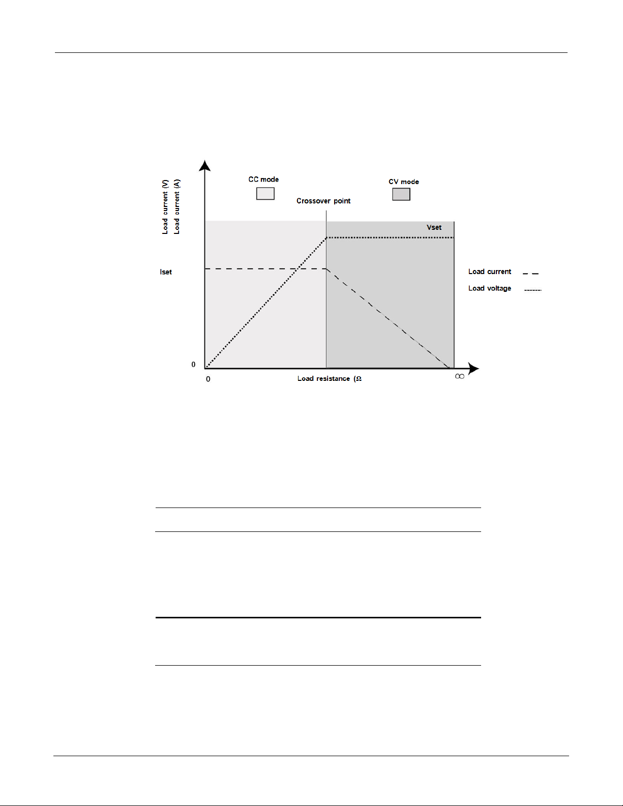
Series 2268 850 Watt DC Power Supplies Reference Manual Local Operation
Important: If you can't get the set point to the desired level, you may need to
change the set points for OVP.
Important: The control circuits have been designed to allow you to set the
specification is not guaranteed.
Quick Ti p: Remote
The SCPI command (s) for these instructions are:
[:AMPLitude]
The reverse operating mode change can also occur if the load resistance is increased to the
point that the required load current drops below the I
value. At that point the power
SET
supply would crossover to CV mode and the load current would be free to vary as the load
resistance changed.
Figure 12: Operating Modes
To set the voltage set point (V
1. Turn the 9-position mode control to the VOLTS position or press the rotary
Adjust/Ente r con tro l if th e 9 -position mode control is already at the VOLTS
position.
The voltage set point is blinking in the output voltag e display. The output current will be
displayed in the output current display.
2. Set the desired voltage value using the rotary Adjust/Enter control.
3. Press the rotary Adjust/Enter control to transition to Fine Adjust mode.
The set point will blink faster to indicate fine adjust tracking mode.
4. Set the desired voltage value using the rotary Adjust/Enter control.
5. Once the desired value has been set, press the rotary Adjust/Enter control to
commit the setting.
output voltage up to 105% over the model-rated maximum value. The power
supply will operate within these extended ranges, but full performance to
SET
):
operation uses these
SCPI commands. See
page 101.
2268S-901-01 Rev. A / January 2015 39
[[:]SOURce[<channel>]]:VOLTage[:LEVel][:IMMediate]
Page 42

Local Operation Series 2268 850 Watt DC Power Supplies Reference Manual
Important: The maximum and minimum setting values of the output voltage
settings.
Important: The control circuits have been d esigned so that output current can
will operate within these extended ranges, but full performance to specification
is not guaranteed.
are limited by the Over Voltage Protection and Under Voltage Protection
To set the current set point (I
SET
:
)
1. Turn the 9-position mode control to the AMPS position or press the rotary
Adjust/Ente r con tro l if th e 9 -position mode control is already at the AMPS
position.
The voltage set point is blinking in the output voltage display. The output current will be
displayed in the output current display.
2. Set the desired current value using the rotary Adjust/Enter control.
3. Press the rotary Adjust/Enter control to transition to Fine Adjust mode.
The set point blinks faster to indicate fine adjust tracking mode.
4. Set the desired current value using the rotary Adjust/Enter control.
5. Once the desired value has been set, press the rotary Adjust/Enter control to
commit the setting.
be set up to 105% over the model-rated maximum values. The power supply
The SCPI command (s) for these instructions are:
[[:]SOURce[<channel>]]:CURRent[:LEVel][:IMMediate] [:AMPLitude]
40 2268S-901-01 Rev. A / January 2015
Page 43

Series 2268 850 Watt DC Power Supplies Reference Manual Local Operation
Local Control Configuration
Additional References
Use the front panel controls to
See section on “Local Operation” on page 30
programming procedures.
The OVP set point is adjusted at
voltage.
See “Using Over Voltage Protecti on (OVP)”
Important: The main output will not turn on i f the shutdown fu nction is
activated. See “Using the External Shutdown Function” on page 53.
Quick Ti p: Remote
101.
SHIPPED CONFIGURATION (LOCAL OPERATION)
The power supply is configured for local operation at the factory. See the table that follows
for a summary of this configuration.
adjust the output voltage and
current set point settings.
the front panel to 105% above
the maximum rated output
ENABLING THE OUTPUT
Enabling the output on will also turn off the ALARM LED if the ALARM LED has been
latched on due to an alarm triggering and au tomatically clea ring. See “Al arms and E rrors” on
page 44.
To enable the output power:
♦ Press the OUTPUT ENABLE Main button on the front panel or enter the SCPI
To disable the output power:
♦ Press the OUTPUT ENABLE Main button when the OUTPUT ENABLE Main button
command.
The OUTPUT ENABLE Main button will illuminate.
is illuminated.
for front panel operation. See section on,
“Analog Programming & Isolated Analog
Programming” on page 72 for analog
on page 50 for the adjustment procedure.
The output will be disabled and the LEDs will not be illuminated.
operation uses these
commands. See page
The SCPI command (s) for these instructions are:
[:]OUTPut[<channel>][:POWer][:STATe]
2268S-901-01 Rev. A / January 2015 41
Page 44

Local Operation Series 2268 850 Watt DC Power Supplies Reference Manual
Important: The auxiliary output will not be enabled if the external
87.
ENABLING THE AUXILIARY OUTPUT
To enable on the auxiliary output:
♦ Press the OUTPUT ENABLE Aux butto n on the front panel .
The OUTPUT ENABLE Aux button will illuminate.
AUX_ON_OFF signal line is be ing used to disable the auxiliary outputs. See
“AUX Output and Isolated Analog Programming (ISOL) Connector” on page
To disable the auxiliary output:
♦ Press the OUTPUT ENABLE Aux button on the front panel again. The OUTPUT
ENABLE Aux button will not be illuminated.
If the auxiliary output is activated, +5 V on J3.9 (+AUX1) and +15 V on J3.11 (AUX2)
will be present with respect to Pin J3.2 or Pin J3.6 (COM ISOLATED). (See also “
Output and Isolated Analog Programming (ISOL) Connector
The SCPI command (s) for these instructions are:
[:]OUTPut[<channel>]:AUXiliary[:STATe]
AUX
” on page 87 for more details.)
OUTPUT AUTO START MODE (AUTO RESTART)
The Auto Start mode establishes the state of the output of the power supply after recovery
from a complete power cycle (all front panel LEDs are not illuminated).
If Auto Start mode is set to On, the power supply output will return to its previous value
when the power supply is powered up again.
If Auto Start mode is set to Off, the power supply output will remain off after the power
supply is powered up again.
To change the Auto Start mode:
1. Press and hold the OUTPUT ENABLE Main button for 1 second. or
is displayed.
2. Switch the Auto Start mode.
The SCPI command (s) for these instructions are:
[:]OUTPut[<channel>][:POWer][:STATe]:PowerON[:STATe]
42 2268S-901-01 Rev. A / January 2015
Page 45

Series 2268 850 Watt DC Power Supplies Reference Manual Local Operation
AUXILIARY AUTO START MODE
The Auxiliary Auto Start mode determines the state of the auxiliary output after a complete
power cycle (all front panel LEDS are not illuminated). With Auxiliary Auto Start mode
turned to On, the auxiliary output will be activated after the power supply is powered up
again.
To define the Auxiliary Auto Start mode:
1. Press and hold the OUTPUT ENABLE Aux button for 1 second. or
is displayed.
2. To change to status to On or Off, press the OUTPUT ENABLE Aux button.
The SCPI command (s) for these instructions are:
[:]OUTPut[<channel>]:AUXiliary:PowerON[:STATe]
CONSTANT POWER MODE
In Constant Power Mode the power supply will continually adjust the current levels to
maintain a constant power set point. T his mod e is inten ded pr imarily fo r loads w ith respons e
time greater than approximately 100m s. In order to p rovide additional pro tection for the load,
voltage and current limits may be set while in the constant power mode. If the unit cannot
regulate to the Constant Power setting due to load conditions, it will regulate at either the
voltage or the current limit depending on the load demand.
Example, CP Mode:
Constant Power set 500W
Voltage limit 61V
Current limit 20A
To activate Constant Power mode and set the value:
1. Turn the 9-position mode control to the FLD position or press the rotary
Adjust/Ente r cont rol if the 9 -position mode cont rol is already at the FLD position.
2. Turn the rotary Adjust/Enter control until “CP” is displayed.
3. Press the rotary Adjust/Enter control.
4. Turn the Adjust/Enter control to the desired set point.
5. Press the rotary Adjust/Enter control.
6. Turn the Adjust/Enter control for fine adjustment.
7. Press the rotary Adjust/Enter control to commit the Constant Power operation.
To disable Constant Power operation:
1. Turn the 9-position mode control to the FLD position or press the rotary
Adjust/Ente r cont rol if the 9 -position mode control is already at the FLD position.
2. “FLD” is displayed on the output voltage display and the output current display
shows the Constant Power mode “CP”.
2268S-901-01 Rev. A / January 2015 43
Page 46

Local Operation Series 2268 850 Watt DC Power Supplies Reference Manual
Alarm
Precedence
Output
Maskable
Display
AC Fail
1 (Highest)
Yes
No
Over Temperature Protection (OTP)
2
Yes
No
OtP
Fan 4 No
Yes
Interlock
6
No
No
In Loc
Over Voltage Protection (OV P)
7
Always
No Over Current Protection (OCP)
8
Always
No Foldback
9
Yes
Yes External Shutdown
10
No
Yes Under Voltage Protection (UVP)
11 (Lowest)
No
Yes
Current Loop Protection
12 (Lowest)
Loop Pro
Flash Checksum Failure
1
N/A
N/A
N/A
3. Turn the rotary Adjust/Enter control until “NONE” is display ed in the ou tp u t
current display.
4. Press the rotary Adjust/Enter control to commit the setting once the desired value
has been set.
5. The green FLD LED wi ll turn o ff and the display w ill return t o the norm al disp lay
mode.
The SCPI command (s) for these instructions are:
[:]SOURce[<channel>]:POWer:MODe[:STATe]
[:]SOURce[<channel>]:POWer:LEVel
ALARMS AND ERRORS
Several conditions can cause alarms in the POWER SUPPLY. Some conditions are:
• From user configurable features.
• Controlled in hardware and will trigger regardless of configuration.
All alarms, w ith the exception of the Fan alarm, will result in the output of the po wer supp ly
being disabled. The Fan alarm does not affect the output.
When an alarm is triggered, the approp riate alarm messag e will begin blinking on t he display
and the Alarm LED will be il luminate d. I t is poss ible th at m ore tha n one a larm will tr igg er at
the same time. When this occurs, the alarm with the highest precedence will blink on the
display.
The table that follows lists the precedence of alarms. If the alarm is cleared and the
event which caused the alarm has not been corrected, then the alarm may trigger again
immediately. Fix the reason for the alarm before you clear it.
Latch
1.
The Flash Checksum Failure alarms are an exception as they can only occur during boot up or
recalling a user setting slot. If a check sum error is detected wh en recalling a user s lot, no m odif ication of
settings will occur, and an error will be pushed to the SCPI error queue. If a checksum occurs at boot-up,
then this checksum error can be cleared by doing a soft reset or by power cycling the unit.
44 2268S-901-01 Rev. A / January 2015
Page 47

Series 2268 850 Watt DC Power Supplies Reference Manual Local Operation
Important: When an alarm is cleared by using this method, only the current
now become the highest precedence alarm and will begin blinking on
the display.
CLEARING ALARMS
Clearing Triggered and Manual Alarms
To clear a triggered alarm, use one of the following methods:
• Turn the power supply Off and then On.
• Press and hold the rotary Adjust/Enter control for 3 seconds.
To clear a manual alarm:
1. Press and hold the rotary Adjust/Enter control for 3 seconds.
The message will be displayed on the front panel for a few seconds.
highest precedence alarm is cleared. If another alarm has occurred, then this
alarm will
2. Repeat the alarm clearing until you have cleared all alarms.
Clearing a Flash Failure Alarm
The Flash Failure alarm is the only exception for clearing alarms. If a flash failure occurs at
boot time, it can only be cleared by a soft reset key combination press (see “Resetting the
Power Supply” on page 62) or by power cycling the unit. If a checksum error is detected
when recalling a user slot, no modification of sett ings will occur, and an error will b e pushed
to the SCPI error queue. The alarm will clear after a duration per the currently configured
front panel timeout setting.
To clear a triggered alarm, use one of the following methods:
• Turn the power supply Off and then On.
• For failures that occur during a recall of user memory settings, wait the duration of the
currently configured front panel timeout.
• Press and hold the res et key combination (Flash Fail ONLY). See “Resetting the Power
Supply” on page 62.
The SCPI command (s) for these instructions are:
[:]OUTPut[<channel>]:PROTection:CLEar
2268S-901-01 Rev. A / January 2015 45
Page 48

Local Operation Series 2268 850 Watt DC Power Supplies Reference Manual
Clearing Automatic Alarms
Some alarms will clear automatically when the condition that caused the alarm is no longer
present. When an alarm automatically clears, the output voltage and current displays will
return to normal, but the ALA R M L E D w ill remain illum inate d to indicate that an alarm has
occurred. If an automatic alarm is triggered, the normal alarm clearing procedure still
applies.
To clear the ALARM LED after an automatic alarm has cleared, use one of the
following methods:
• Send the SCPI Clear Alarm command.
• Press the OUTPUT ENABLE Main button to reenable the output. The ALARM LED
For example, if one of the fans was temporarily blocked, causing a Fan alarm, then the
blockage was cleared and the fans restarted, the alarm would clear. The output voltage and
current displays would be in normal mode, but the ALARM LED would be illuminated. See
“Front Panel Alarm LED” on page 46 for information on other ev ents that affect the A LARM
LED.
Alarms status is tracked in the SCPI status registers. For more details on how and where the
alarms are tracked, see “Standard SCPI Register Structure” on page 134.
will no longer be illuminated.
Front Panel Alarm LED
The Alarm LED will illuminate due to one or more of the following events occurring:
• OTP has been tripped.
• A fan has stopped.
• OVP has tripped.
• OCP has tripped.
• UVP has tripped
• Interlock is open circuit.
• AC power falls out of range.
• Foldback has tripped.
• Persistent storage checksum is wrong (Flash Fail alarm).
• Internal malfunction of power supply.
• Any alarm has tripped and been cleared automatically.
46 2268S-901-01 Rev. A / January 2015
Page 49

Series 2268 850 Watt DC Power Supplies Reference Manual Local Operation
Alarm
Bit Position
Value
Over Temperature Protection (OTP)
2 2
Not used
3 4
Fan 3 8
Foldback
8
256 External Shutdown
9
512 Under Voltage Protection (UVP)
10
1024
The alarm LED will remain illuminated until the alarm is manually cleared (see “Clearing
Triggered and M anual A larm s” on pag e 45) or by turning the m ain output on if the al arm has
automatically been cleared.
Alarm Masking
It is possible to completely disable some alarms through the use of the alarm mask. If an
alarm is masked then this masking will prevent it from registering in the SCPI conditions
registers as well as not triggering the alarm. The alarms that can be masked are identified in
the table on page 44. Setting the bit position (1) of an alarm will result in the alarm being
enabled. Clearing the bit position (0) of an alarm will result in the alarm being
masked/disabled.
For Example:
If you wanted to enable the OTP, Foldback and UVP alarms, you would take the foldback
value of 256 and the UVP value of 1024 to get a mask of 1280. This is the value you would
send with the SCPI command.
Control of the alarm mask is only available using the SCPI command.
The SCPI command (s) for these instructions are:
[:]SYSTem[<channel>]:PROTection:MASK
The mask command tak es a single param eter made u p of the sum of the values for the ala rms
that are to be masked. See the table that follows for the alarm values associated with each
maskable alarm.
The SCPI command (s) for these instructions are:
[:]SYSTem[<channel>]:PROTection:MASK
2268S-901-01 Rev. A / January 2015 47
Page 50

Local Operation Series 2268 850 Watt DC Power Supplies Reference Manual
Alarm
Bit
Position
Value
AC Fail
0
1
Over Temperature Protection (OTP)
1
2
Foldback
8
256
Alarm Output Latching
When an alarm is triggered, the output will be disabled with the exception of the Fan alarm.
When an alarm is cleared, the alarm output latch determines if the output should be
re-enabled to the state before the alarm occurred or if the output should remain in the off
state.
Where setting the bit position (1) of an alarm latch will result in output latching to the off
state when the alarm is c lea red an d if c le a red (0) output w il l b e re-enabled to the state b e fore
the alarm triggered.
To define the values for the bit position you determine which alarms y ou want to latch. Read
the value for this bit position from the table th at follo w s and sum them together. The result is
the alarm last mask, which you should send with the SCPI command.
For Example:
If you wanted to enable latching for OTP and Foldback you would take the OTP value of 2
and add it to the foldback value of 256 to get a m ask of 258. This is the v alue you would send
with the SCPI command.
The output latches are accessible through the SCPI command.
The SCPI command (s) for these instructions are:
[:]SYSTem[<channel>]:PROTection:LATCh
The latch comm and take a s ingle d ecim al param eter m ade up of the sum of the valu es for the
alarms to determine if they are to be latched in the off state on clearing. See the following
table for the values associated with each latchable alarm.
48 2268S-901-01 Rev. A / January 2015
Page 51

Series 2268 850 Watt DC Power Supplies Reference Manual Local Operation
Important: If you set f ol dback whi l e th e ou t put is en abl ed a n d t h e t rig g er you
counting immediately after the delay time has been set.
SETTING FOLDBACK MODE
Foldback mode is used to disable the output when a tran sition is m ade between the operati ng
modes. The power supply will turn off/disable the output and lock in foldback mode after a
specified delay if the power supply t ransitions into C V m ode or into C C m ode, depending on
the foldback mode settings. This feature is particularly useful for protecting current or
voltage sensitive loads. Fold back can be set to trigger a switch w hen transitioning from CV to
CC mode or from CC to CV mode.
To set the foldback protection and foldback delay time:
1. Turn the 9-position mode control to the FLD position or press the rotary
Adjust/Ente r cont rol if the 9 -position mode cont rol is already at the FLD posi tion .
2. Select the type of crossover that will cause foldback to trigger by using the rotary
Adjust/Enter control.
If the mode selected is CC or CV mode, the foldback delay timer will start on a
transition into the selected mode. If the mode selected is none, foldback is not enabled.
3. Press the rotary Adjust/Enter control when the desired mode has been selected.
The FLD LED will illuminate and will be disp layed in the o utput v oltag e disp lay.
4. Adjust the desired delay time using the rotary Adjust/Enter control.
The range can be set from 0.50 seconds to a maxim um of 50 seconds. The s tep size is in
increments of 0.05 seconds when setting from 0.50 to 5 seconds and then in 1 second
increments from 5 seconds to 50 seconds.
5. Once the desired foldback delay time has been selected, press the rotary
Adjust/Enter control to commit the foldback delay setting.
To disable foldback protection:
1. Turn the 9-position mode control to the FLD position or press the rotary
Adjust/Enter control if the control knob is already at the FLD position.
2. is displayed on the output voltage display and the output current display
shows the current foldback trigger mode.
3. Turn the rotary Adjust/Enter control until is displayed in the output current
display.
4. Press the rotary Adjust/Enter control to commit the setting once the desired value
has been set.
5. The green FLD LED wi ll turn o ff and the display w ill return t o the norm al disp lay
mode.
The SCPI command (s) for these instructions are:
[:]OUTPut[<channel>]:PROTection:FOLDback[:MODE]
[:]OUTPut[<channel>]:PROTection:FOLDback:LATCh
select is the same as the current operating mode, the foldback timer will begin
2268S-901-01 Rev. A / January 2015 49
Page 52

Local Operation Series 2268 850 Watt DC Power Supplies Reference Manual
Important: The OVP range is variable from V
SET
+5% to V
MAX
+25%.
RESETTING ACTIVATED FOLDBACK PROTECTION
To reset activated and latched foldback protection, press and hold the rotary Adjust/Enter
control for approximately 3 seconds.
The SCPI command (s) for these instructions are:
[:]OUTPut[<channel>]:PROTection:CLEar
USING OVER VOLTAGE PROTECTION (OVP)
The OVP circuit protects the load in the event of an analog programming error, an incorrect
voltage control adjustment, or a power supply failure. The OVP circuit monitors the output
voltage at the output of the power supply and will disable the output whenever a preset
voltage set point is exceeded. You can set the preset voltage trip point by using the 9-position
mode control on the front panel or via one of the remote programming interfaces.
To prevent accidental tripping of the OVP while setting up, the firmware will prevent the
OVP set point from being less than 105% of the voltage set point when in local set point
control mode. When the power supply is in VAP mode for defining voltage set point the set
point limitation will be based on the VAP input signal level. The user should note it is
possible to trip OVP in this mode if the OVP is configured when the analog programming
source is off.
When the user attempts to configure an OVP setpoint that is less than 105% of the voltag e set
point via the front panel the set point will stop allowing the value to decrement. If the user
attempts to configure an OVP set point that is less than 105% of the voltage set point via
SCPI a -221, “settings conflict error” will be pushed onto the error queue.
Defining the OVP Set Point
To define the OVP set point:
1. Turn the power supply On.
Ensure the voltage is lower than the desired set point.
2. Set the output to the desired voltage.
OVP can be set without setting desired output voltage first.
3. Turn the 9-position mode control to the PRT position. Προ ΟΥΠ is displayed.
4. Press the rotary Adjust/Enter control.
5. Turn the rotary Adjust/Enter control to set the upper limit protection. See “Coarse
and Fine Adjustment Modes” on page 31.
6. Once the desired value has been set, press the rotary Adjust/Enter control to
commit the setting.
The SCPI command (s) for these instructions are:
[[:]SOURce[<channel>]]:VOLTage:PROTection[:OVERvoltage] [:LEVel]
If the output is between OVP
APG mode.
and -5%, an OVP warning message is possible when in
set
50 2268S-901-01 Rev. A / January 2015
Page 53

Series 2268 850 Watt DC Power Supplies Reference Manual Local Operation
Important: UVP will not be active for voltage set points that are less than 1%
of model voltage.
Important:
The UVP range is variable from 0 volts to OVP
SET
-10%.
USING UNDER VOLTAGE PROTECTION (UVP)
The UVP prevents voltage settings below a set value. The UVP lets you create a voltage
window of operation when used in conjunction with the OVP setting. The UVP range is
variable from 0 V to OVP
The UVP is a protection that becomes active after the output is enabled and a period of time
has passed to allow the output to reach its set point value before the UVP protection begins
monitoring. As with OVP if the v oltag e se t poin t is dete rm ined by ana log con trol ( VAP) an d
the voltage strays to within 5% of the UVP set point then UVP Safe will trigger to warn the
user that they are about to trigger the UVP alarm.
The period of time before the UVP monitoring is active after the output is enabled is
determined by the rise-time delay for the model. Since the rise time is based on a purely
resistive load the use r shou ld be awar e that U VP trigg ering m ight be possib le in cap acitive or
rectifier lo ads due to the ris e time being longer. I n these cases it is recomm ended that the user
mask the UVP alarm until the r ise tim e has elapse d and then unm ask the alarm to allow U VP
protection to be enabled during operation.
-10%.
SET
Defining the UVP Set Point
To define the UVP set point:
1. Turn the power supply On.
2. Set the output to the desired voltage.
3. Turn the 9-position mode control to the PRT position. is displayed.
4. Turn the rotary Adjust/Enter control until is displayed.
5. Press the rotary Adjust/Enter control to select the UVP for setting up.
6. Set up the lower limit protection using the rotary Adjust/Enter control.
7. Once the desired value has been set, press the rotary Adjust/Enter control to
commit the setting.
See “Coarse and Fine Adjustment Modes” on page 31.
The SCPI command (s) for these instructions are:
[[:]SOURce[<channel>]]:VOLTage:PROTection:UNDer[:LEVel]
OVER CURRENT PROTECTION (OCP)
The OCP alarm is a firmware alarm that is only configurable using the SCPI interface. The
OCP triggers if the output current exceeds the OCP set point. Because the OCP alarm is a
firmware based alarm it has a latency before detection of the condition can occur. The user
should be aware of this latency and take this into consideration when relying on OCP to
protect a sensitive load. The maximum period for detecting an OCP condition is 300 ms.
OCP is fixed at 110% of rated current.
2268S-901-01 Rev. A / January 2015 51
Page 54

Local Operation Series 2268 850 Watt DC Power Supplies Reference Manual
USING OVER TEMPERATURE PROTECTION LOCK (OTP)
The OTP lock protects the power supply in the event of an over temperature alarm. This
alarm could be caused by ventilation restriction or overheating due to fan failure.
Two modes are available:
• Auto recovery (OTP OFF) where the power supply turns on again after cooling down.
• Latch mode (OTP ON) where you will need to reset the unit by turning the front panel
power switch to Off and then On again.
If the OTP is activated, the main output will turn off and
protection) will blink on the display. The OTP a larm is an alarm that will auto recov er w hen
the temperature falls back into normal bounds.
Defining the OTP Mode
To define the OTP lock:
1. Turn the 9-position mode control to the PRT position. PrO OUP is displayed.
2. Turn the rotary Adjust/Enter control until is displayed.
3. Press the rotary Adjust/Enter control to display .
4. Turn the rotary Adjust/Enter control to change to On or Off.
5. Press the rotary Adjust/Enter control.
The SCPI command (s) for these instructions are:
[:]SYSTem[<channel(s)>]:PROTection:LATCh
Resetting in Latch Mode
To reset the powe r supply if the OTP alarm is t ripped and th e OTP m ode is set to On ( latching
enabled), press and hold the rotary Adjust/Enter control for approximately 3 seconds.
The SCPI command (s) for these instructions are:
[:]OUTPut[<channel(s)>]:PROTection:CLEar
[:]SYSTem[<channel(s)>]:PROTection:LATCh
(over temperature
52 2268S-901-01 Rev. A / January 2015
Page 55

Series 2268 850 Watt DC Power Supplies Reference Manual Local Operation
USING THE EXTERNAL SHUTDOWN FUNCTION
Use the external shutdown function to enable or disable the outpu t of the pow er su pply v ia a
logic level signal. Wh en the external shutdown is triggered, the power supply will display SD
POL on the output voltage and current displays. The external shutdown is useful for making
adjustments to either the load or the power supply without shutting off the power supply or
for using the power supp ly as pa rt of a larg er tes t syste m in which dig ital or ana log control is
required.
Activating the External Shut down Function
To activate the external shutdown function, use the AUX output supply provided on the
Analog Programming Connector J3. This input has a user selectable polarity with logic low
input from 0.0V to 1.2V and logic high from 2.0V to 15V. The control signal for this input
must be capable of sinking 10mA minimum. This input is also compatible with the use of dry
contacts, where a short is logic low and an open is logic high. The input lines of the shutd own
circuit are fully optically isolated.
Once the External Shutdown has been triggered, the display will blink the .
Controlling the Exter na l S hut down Function
The external shutdown circuit accepts a voltage or dry contact control (high or low logic
level) to enable or disable the power supply output. Make connections for the signals at the
AUX Output and Isolated Analog Programming Connector on the rear panel. (See “AUX
Output and Isolated Analog Programming (ISOL) Connector” on page 87 for more
information.)
To activate the shutdown function:
Connect the control signal source to the Shutdown pin (J3.12) on the Aux Output and
Isolated Analog Programming Connector with the control circuit ground connected to
Isolated Ground pin (J3.6).
The External Shutdown pin is pulled high internally (normally high). Therefore, if this
feature is not used, the polarity should be set to 1 to avoid false triggering. (See “D efining the
Polarity of the External Shutdown Signal” on page 54 for instructions.)
2268S-901-01 Rev. A / January 2015 53
Page 56

Local Operation Series 2268 850 Watt DC Power Supplies Reference Manual
Important:
There is an internal pullup resistor inside the shutdown circuit so
the shutdown polarity should be set to 0 if it is not being used.
Important:
While Loop Protection is enabled (ON), the external shutdown
setting.
Defining the Polarit y of the Exter na l Shutdown Signal
1. Turn the 9-position mode control to the PRT position or press the rotary
Adjust/Enter control if the control knob is already at the PRT position.
is displayed on the output voltage display.
2. Turn the rotary Adjust/Enter control until is displayed.
3. Press the ro tary Adjust/En ter con trol to d isplay (shutdown on logic 0) or
(shutdown on logic 1).
4. Press the rotary Adjust/Enter control to commit the desired polarity setting.
For example: If you set the shutdown logic to 1 ( ) and apply a logic high (greater
than 1.2 Vdc) to pin J3.12 relative to pin J3.6 on the ISOL connector, the power supply
will shut down. Conversely, if you se t the shutdown lo g ic to 0 (
will only operate when you have a logic high (greater than 1.2 Vdc) to pin J3.2 relative
to pin J3.6.
The SCPI command (s) for these instructions are:
[:]OUTPut[<channel>]:POLarity
), the power supply
LOOP PROTECTION
The Loop Protection feature can be used to enable or disable multiple units in daisy chain
configuration through the AUX Output and Isolated An alog Programming Connector, J3. Up
to four units (example, Units #1 through #4) can be configured in Loop Protection; if one of
the units is experiencing a fault condition, other units in the same loop will disable their
output simultaneously. This is achieved by connecting Unit #1’s MAIN_PS_GOOD to Unit
#2’s SD (Shutdown Main O/P) and continues until Unit #4’s MAIN_PS_GOOD is fed to
Unit #1’s SD (Shutdown Main O/P). Common applications include s ingle master controlling
multiple slave units as a sy stem O n/Off. In addition, any fault from either o peratin g unit wil l
cause the system to disable.
The Loop Protection can be enabled o r disabled locally using the front panel 9-position m ode
control, or remotely using a SCPI command.
function will be automatically set to low active. When Loop Protection is
disabled (OFF), the external shutdown function will be set to the user’s last
Setting up Loop Protecti on
To set up Loop Protection:
With the AC powered OFF, connect the first unit’s pin J13.13 to the next unit’s J 13.12 on the
AUX Output and Isolated Analog Programming Connector. Do this for up to four units. An
example of a 3-unit loop protection is illustrated as follows:
54 2268S-901-01 Rev. A / January 2015
Page 57

Series 2268 850 Watt DC Power Supplies Reference Manual Local Operation
Figure 13: Loop Protection Setup
To enable or disable Loop Protection:
1. Turn the 9-position mode control to the PRT position. PRO OVP is displayed.
2. Turn the rotary Adjust/Enter control until LOOP PRO is displayed.
3. Press the rotary Adjust control to display LOOP ON or OFF.
4. Press the rotary Adjust control to change the setting to ON or OFF.
5. Press the rota ry Adjust con trol to accep t the chang e.
The SCPI command (s) for these instructions are:
[:]OUTPut [<channel>]:PROTection:Loop[:STATe]
2268S-901-01 Rev. A / January 2015 55
Page 58

Local Operation Series 2268 850 Watt DC Power Supplies Reference Manual
INTERLOCK FUNCTION
The Interlock function can be used to wire an external shutoff switch that can be used to
enable or disable the power supply output. When the switch is closed, the power supply will
operate normally. If the switch is opened, the power supply will trigger the interlock alarm.
The output will be disabled, the display will blink
illuminate. This alarm will automatically clear when the switch closes again, and the output
will autom atically be res tored to its pr e-alarm state (either en abled or di sabled). Th e interlock
function can only be enabled or disabled (defined) using a SCPI command (cannot be
masked or latched through the alarm protection mechanisms.). C ommon applications include
an emergency shutoff switch or a door switch.
Connect the switch between pins J3.14 and J3.15 on the AUX Output and Isolated Analog
Programming Connector.
Defining the Interlock Mode
The Interlock mode is controlled via SCPI commands. There is no front panel access for
enabling or disabling the Interlock functionality. See “Interlock Enable/Disable” on page
161.
The SCPI command for setting the Interlock mode to On or Off is:
[:]SENSe[<channel>]:PROTection:INTerlock[:STATe]
, and the ALARM LED will
OUTPUT PROTECTION
The output voltage and the output current can be programmed (preset) to automatically start
at zero Volts and zero Amps upon power-up and upon output enable. Also, each can be
reprogrammed to disable the automatic reset to zero.
Programming Voltage Output Pre s e t
To Enable/Disable automatic reset to 0 Volts:
1. Turn the rotary Adjust/Enter control to PRT and press.
2. Turn again until is display ed.
3. Press to display .
4. Turn to display or .
5. Press to commit the selected setting.
Important: This single front panel operation affects both power on and output enable.
However, when using SCPI, there is a separate command for each.
The SCPI command to query or enable/disable the 0 Voltage Output Preset at
power-on is:
[:]SYSTem[<channel>]:PON:VOLTage {?|ON|OFF}
The SCPI command to query or enable/disable the 0 Voltage Output Preset upon
output enable is:
[:]SYSTem[<channel>] :PON:ENAble:VOLTage {? |ON|OFF}
56 2268S-901-01 Rev. A / January 2015
Page 59

Series 2268 850 Watt DC Power Supplies Reference Manual Local Operation
Programming Current O ut put Pr e set
To Enable/Disable automatic reset to 0 Amps:
1. Turn the rotary Adjust/Enter control to PRT and press.
2. Turn again until is displayed.
3. Press to display .
4. Turn to display or .
5. Press to commit the selected setting.
Important: This single front panel operation affects both power on and output enable.
However, when using SCPI, there is a separate command for each.
The SCPI command to query or enable/disable the 0 Current Output Preset at
power-on is:
[:]SYSTem[<channel>]:PON:CURRent {?|ON|OFF}
The SCPI command to query or enable/disable the 0 Current Output Preset upon
output enable is:
[:]SYSTem[<c hannel>] :PON:ENAbl e:CURRent {? |ON|OFF}
POWER ON STATUS SIGNAL
Power On Status signal indicates a fault condition in the power supply. Power On Status
signal is a TTL output signa l at Pin J2.13 wi th reference to CO M ISOLATED (Pin J2.2 or Pin
J2.6).
During normal operation, the Power On Status signal will be high. If the output is disabled
for any reason, the Power On Status signal will go low.
The following conditions will set the Power On Status to a low level:
• AC fail
• Current Loop Protection
• Over Voltage Protection (OVP)
• Under Voltage Protection (UVP)
• Over Current Protection (OCP)
• Over Temperature Protection (OTP)
• Foldback Protection
• Interlock
• Output Off
• Shutdown activated (rear panel shutdown).
• Internal hardware malfunction Fan failure
2268S-901-01 Rev. A / January 2015 57
Page 60

Local Operation Series 2268 850 Watt DC Power Supplies Reference Manual
Voltage Setpoint
Current Setpoint
Voltage Output Protection
Current Output Protection
Over Voltage Protection (OV P)
Under Voltage Protection (UVP)
Over Temperature Protection (OTP)
Autostart OUTPUT ENABLE Main
Autostart OUTPUT ENABLE Aux
Foldback Mode
Foldback Delay
Shutdown Logic
Voltage Analog Programming (VAP) Mode
Voltage Analog Programming (VAP) Level
Current Analog Programming (CAP) Mode
Current Anal og Programming (CAP) Level
Remote Programming Interface
Local Lock
PSU (Power Supply) Address
Data Rate (BPS)
Alarm Latches
Front Panel Timeout
Constant Power Mode
Constant Power Level
Loop Protection Enable
Line Drop Mode Settings
HARDWARE MALFUNCTION ALARMS
The power supply will turn off the output. An error message will be displayed in the event
that:
• OVP trips
• Voltage deviation in CV mode reaches more than ±5% from the set level.
• Current deviation in CC mode reaches more than ±5% from the set level.
1
1
__________________________
1. These two forms of hardware malfunction are only monitored in the corresponding APG mode.
CURRENT CONFIGURATION MEMORY SETTINGS
The power supply will save the u nit settings at the tim e of power down. These settings will be
loaded when the power is restored to the unit or the power supply is powered up again. The
table that follows lists the settings that are saved and recalled on a power cycle event.
58 2268S-901-01 Rev. A / January 2015
Page 61

Series 2268 850 Watt DC Power Supplies Reference Manual Local Operation
Voltage Setpoint
Current Setpoint
Voltage Output Protection
Current Output Protection
Over Voltage Protection (OVP)
Over Temperature Protection (OTP)
Autostart OUTPUT ENABLE Main
Autostart OUTPUT ENABLE Aux
Foldback Mode
Foldback Delay
Shutdown Logic
Voltage Analog Programming (VAP) Mode
Voltage Analog Programming (VAP) Level
Current Analog Pro gramming (CAP) Mode
Current Anal og Programming (CAP) Level
Current Sharing Mode
Alarm Latches
Front Panel Timeout
USER SETTING MEMORY LOCATIONS
There are three user setting memory locations available for storing frequently used
configurations. These user setting memory locations help to facilitate multiple users of a
Series 2268 power supply who have different setups or when multiple loads are used that
have different requirem ents. The table that f ollows list s the valu es that a re stored in each user
setting memory location.
Saving User Setting Memory Locations
To save user setting memory locations:
1. Turn the 9-position mode control to the SAV position.
is displayed on the output voltage display with a number indicating a preset
position which is displayed on the output current display.
2. Turn the rotary Adjust/Enter control to select a preset position from 1 to 3.
3. Press the rotary Adjust/Enter control.
done is displayed on the output voltage display.
4. The setting has now been saved to the selected user setting memory location.
The SCPI command (s) for these instructions are:
*SAV <setting_location>
or
[:]SYSTem[<channel>]:SAVE <setting_location>
2268S-901-01 Rev. A / January 2015 59
Page 62

Local Operation Series 2268 850 Watt DC Power Supplies Reference Manual
Recalling User Setting Me m ory Locations
This feature recalls settings that were previously saved.
To load user setting memory locations:
1. Turn the 9-position mode control to the RCL position.
is displayed on the output voltage display w ith a number indicating a preset position
on the output current display.
2. Turn the rotary Adjust/Enter control to select a preset position from 1 to 3.
3. Press the rotary Adjust/Enter control.
is displayed on the output voltage display.
The settings in the s el ected user se tting m em ory locatio ns have now been app lied to the
power supply.
The SCPI command (s) for these instructions are:
*RCL <setting_location>
or
[:]SYSTem[<channel>]:RECall <setting_location>
Three user setting memo ry locations a re avai lable and one u ser set ting m em ory loca tion
is saved automatically before AC power shutdown. This user setting memory location
will be loaded after AC power is restored.
60 2268S-901-01 Rev. A / January 2015
Page 63

Series 2268 850 Watt DC Power Supplies Reference Manual Local Operation
LOCAL LOCKOUT
Local lockout is a feature that allows the front panel to be locked so that accidental button
presses are ignored. This feature is often used to lockout the front panel when you are
controlling the power supply from a remote location. When in local lockout mode, the front
panel will display
Enabling Local Lockout
To enable local lockout:
1. Turn the 9-position mode control to the PGM position or press the rotary
Adjust/Enter control if the control knob is already at the PGM position.
The display will show in the output voltage disp lay and the select ed remote in terface
in the output current display.
2. Turn the rotary Adjust/Enter control until the display shows .
3. Press the rotary Adjust/Enter control.
4. Turn the rotary Adjust/Enter control until the display shows .
5. Press the rotary Adjust/Enter control. Local lockout has been enabled.
Loc whenever a button is pressed or a knob is turned.
The SCPI command (s) for these instructions are:
[:]SYSTem:REMote:STATe
Disabling Local Lockout
To disable local lockout:
1. Turn the 9-position mode control to the PGM position or press the rotary
Adjust/Ente r con tro l if the control knob is already at the PGM position.
The display will show in the outp ut voltage d isplay and the selected r emote in terface
in the output current display.
2. Turn the rotary Adjust/Enter control until the display shows .
3. Press the rotary Adjust/Enter control.
Local lockout will be disabled after power-cycling the power supply.
The SCPI command (s) for these instructions are:
[:]SYSTem[<channel(s)>]:REMote:STATe
2268S-901-01 Rev. A / January 2015 61
Page 64
Local Operation Series 2268 850 Watt DC Power Supplies Reference Manual
The reset is used to clear the parameters to the factory defau lt values.
Soft Reset
The soft reset is used to set the parameters (see table below) to the
Parameter
Setting
Address
1
Data rate (Kbps)
9.6
Communication mode
RS-232
Vout setting
0 V
Iout setting
0 A
Output
Off
AUX Out
Off
Trigger
Off
Ext. On/Off Polarity
Negative
Auto start mode
Off
AUX Auto start mode
Off
OVP
Maximum
UVP
0 V
Foldback trigger
None
Foldback delay
0.5 s
Current Share Mode
Controller
Alarm Output Latches
263 (0 x 107, all latches enabled)
Alarms Mask
2047 (0 x 7FF, all enabled)
Interlock
Disabled
Voltage Analog Programming
Off
RESETTING THE POWER SUPPLY
default values, but it does not reset the calibration constants
To perform a soft reset:
1. Turn the power supply to Off then On.
When the unit is powering on, is displayed on the output v oltage and current
displays.
2. Press the key com bination of both OUTP UT ENABLE Main bu tton and OUTPU T
ENABLE Aux button and hold continuously for 3 seconds in order to execute.
If the flash fail alarm triggers, it is also possible to reset the power supply. The front
panel should display
.
3. Once a reset has been triggered, the output voltage display shows for 1
second.
The model number will be displayed for 1 second and then return to normal mode.
After executing a reset, the power supply's settings are restored to the default settings but
retain the calib ra tio n da ta . F ollo w in g lis ts the default settings.
62 2268S-901-01 Rev. A / January 2015
Page 65

Series 2268 850 Watt DC Power Supplies Reference Manual Local Operation
Parameter
Setting
Voltage APG Scale
10 V
Current Anal og Programming
Off
Current APG Scale
10 V
Voltage Output Protection
Off
Current Output Protection
Off
greater than 40V or a combin ed output of greater th an 40V. To protec t person nel
of
The remote programming inputs are internally referenced to the power supply's
utput. Do not con nect re m ote prog ramm ing ground li nes to th e pow er
USING MULTIPLE POWER SUPPLIES
WARNING: Shock hazard
There is a shock hazard at the load when using a power supply at an output of
against accidental contact with hazardous voltages created by a series
connection, ensure that the load, including connections, has no live parts which
are accessible. Also ensure that the insulation rating of the load wiring and
circuitry is greater than or equal to the maximum or combined output voltage
the power supply.
CAUTION: Equipment damage
Do not connect power supplies from different manufacturers in parallel or in
series.
CAUTION: Equipment damage
negative o
supply's positive output.
You can operate power supplies of the same model with the outputs in series to obtain
increased load voltage or with the outputs in parallel to obtain increased current, also called
current sharing. Bipolar supply operation gives you two positive outputs, or a positive and a
negative output. When using multiple supplies in series or parallel, they will not meet the
single unit specifications in this Manual.
2268S-901-01 Rev. A / January 2015 63
Page 66
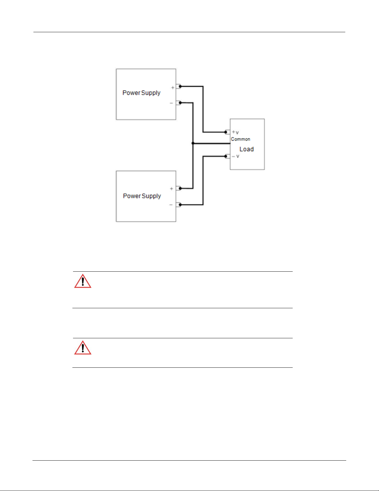
Local Operation Series 2268 850 Watt DC Power Supplies Reference Manual
Figure 14: Bipolar Supply Operation
CONFIGURING MULTIPLE SUPPLIES FOR SERIES OPERATION
A maximum of two power supplies of the same rating can be connected in series to increase
the output voltage.
CAUTION: Equipment damage
When two power supplies are connected in series, they should be programmed
to the same output voltage to pre vent damage to the lower voltage supply at
short circuit condition.
Load Considerations
CAUTION: Equipment damage
Use properly rated diodes to protect the power supply from damage while
driving inductive loads..
INDUCTIVE LOADS:
To prevent damage to the power supply from inductive kickback, connect a diode (rated at
greater than the supply’s output voltage and current) across the output. Connect the cathode
to the positive output and the anode to return. Where positive load transients m ay occur, such
as back EMF from a motor, a second diode in series with the output is recommended to
protect the power supply.
64 2268S-901-01 Rev. A / January 2015
Page 67
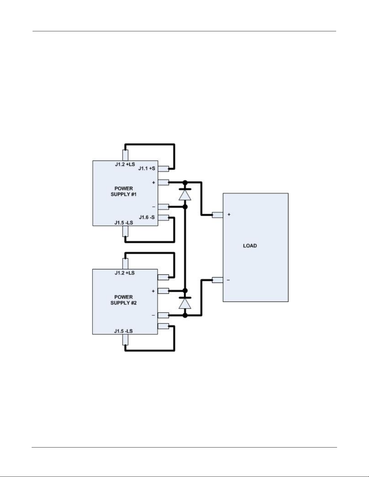
Series 2268 850 Watt DC Power Supplies Reference Manual Local Operation
BLOCKING and FREE WHEELING DIODES:
The Peak Reverse Voltage ratings should be a minimum of 2-3 times the power supply
maximum output voltage. The Continuous Forward Current rating should be a minimum of
1.5 times the power supply maximum output current. Heatsink may be required. There also
may be a need for hi gher vol tage rat ed pa rts , depe nde nt o n loa d cir cuit desi gn a nd in duct or
values.
Connecting to the Load in Local Sensing Mode
Connect the negative (-) output terminal of one power supply to the positive (+) output
terminal of the next power supply. See Figure 15 for a representation of series operation.
Figure 15: Series Operation
2268S-901-01 Rev. A / January 2015 65
Page 68

Local Operation Series 2268 850 Watt DC Power Supplies Reference Manual
Connecting to the Load in Rem ot e Sensing Mode
Connect the negative (-) output terminal of one power supply to the positive (+) output
terminal of the next power supply. The more positive su pply's positive sense line should
connect to the positive terminal of the load (or distribution point). Its return sense line
should connect to the connection between the two units at the same spot as the negative
supply's positive sense line. The return sense line of the negative supply should be
connected to the return of the load. See Figure 16.
CAUTION: Equipment damage
Do not connect sense lines through relays.
Figure 16: Load Connections in Remote Sensing Mode
66 2268S-901-01 Rev. A / January 2015
Page 69

Series 2268 850 Watt DC Power Supplies Reference Manual Local Operation
Important: If current sharing is not being used, the unit must be configured as
a controller. Failure to do so will result in unpredictable operation.
CONFIGURING MULTIPLE SUPPLIES FOR CURRENT SHARING OPERATION (APG METHOD)
Up to four power supplies can be conne cted in para llel to incr ease t he outpu t curr ent. One of
the units will operate as the master unit and the remaining units will operate as slave units
controlled by the master unit. The master unit uses the analog programming lines to set the
output voltages and currents of the slave units to match its output.
In remote digital operation, only the master unit can be programmed remotely while the s lave
units that are connected remotely will only provide voltage, current and status readback
information.
In APG current sharing topologies, only the master unit can be prog rammed using any of the
input methods (front panel, remote digital, or analog prog ramming control). The slave unit(s)
voltage and current output(s) are determined by the master unit through the REF_I input to
each slave unit. The read back using any of the monitoring m ethods (front panel display, us er
monitor lines or SCPI measure commands) of each unit (master or slave) will provide
individual unit status, not system status.
Setting up the Controll er Uni t
Set the output voltag e of th e master unit to the desired v oltag e. Prog ram the current set point
of the master unit to the desired load current set point divided by the number of p arallel units.
During operation, the master unit operates in Constant Voltage mode, regulating the load
voltage at the programm ed outpu t voltag e. Send the C urren t share SC PI comman d or use the
following instructions to program front panel current share setup:
1. With the 9-position mode control at the PGM position, press the rotary
Adjust/Enter control.
is displayed on the output voltage display.
2. Turn the rotary Adjust/Enter control to select and press the
Adjust/Enter control.
is displayed on the output voltage display.
3. Turn the rotary Adjust/Enter control to select in the output current display.
2268S-901-01 Rev. A / January 2015 67
Page 70
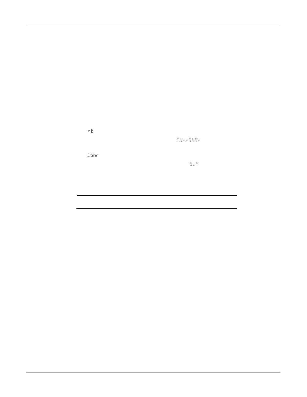
Local Operation Series 2268 850 Watt DC Power Supplies Reference Manual
Important: The slave unit discussed here is not the same as the remote
interface slave described in section 5.
4. Press the rotary Adjust/Enter control to commit the setting.
The SCPI command (s) for these instructions are:
[[:]SOURce[<channel>]]:COMBine:CSHare[:MODE]
Setting up the Slave Units
The output voltage and current of the slave units should be programmed to maximum value.
During parallel operation, the slave un its operate as a c ontrolled curren t source following th e
controller unit's output current.
All slave units must be configured with the SCPI command to enable current sharing, or use
the following instructions to program front panel current share setup:
1. With the 9-position mode control at the PGM position, press the rotary
Adjust/Enter control.
is displayed on the output voltage display.
2. Turn the Adjust/Enter control to select “ ” and press the Adjust/Enter
control.
is displayed on the output voltage display.
3. Turn the rotary Adjust/Enter control to select in the output current display.
4. Press the rotary Adjust/Enter control to commit the setting.
The SCPI command (s) for these instructions are:
[[:]SOURce[<channel>]]:COMBine:CSHare[:MODE]
Setting Over Voltage Protection (OVP)
The master unit's OVP should be programmed to the desired OVP level. The OVP of the
slave units should be programmed to a higher value than the master OVP. When the
controller unit shuts down, it will program the outputs of the slave units to zero volts. If a
slave unit shuts down, only that unit would shut down and the remaining slave units would
supply all the load current if possible.
68 2268S-901-01 Rev. A / January 2015
Page 71

Series 2268 850 Watt DC Power Supplies Reference Manual Local Operation
MASTER PSU
To other slaves
SLAVE PSU
Shielded Twisted Pair
Out
Out
LOAD
Setting Foldback Protection
Foldback protection is only available on the master units as the slaves operate in
constant current mode. They should never crossover into constant voltage mode. If
foldback is triggered on the master unit, when its out put shuts dow n, it will p rogram the
slave unit's output to zero volts.
CONNECTING TO THE LOAD IN LOCAL SENSING MODE (PARALLEL CONTROL METHOD)
Connect the power supplies in parallel to obtain a single output supply with a higher
output current set point. Set al l of the ou tpu ts to the sa m e v oltage before conn ecting the
positive (+) and negative (-) terminals in parallel. The total current available is the sum
of the maximum currents of each power supply.
Figure 17: Load Connections in Local Sensi n g Mode
2268S-901-01 Rev. A / January 2015 69
Page 72

Local Operation Series 2268 850 Watt DC Power Supplies Reference Manual
MASTER PSU
To other slaves
SLAVE PSU
Shielded Twisted Pair
Out
Out
LOAD
CONNECTING TO THE LOAD IN REMOTE SENSING MODE (PARALLEL CONTROL METHOD)
Figure 18: Load Connections in Remote Sensing Mode (Par allel Control Method)
POWER SAVING CONTROL (SLEEP MODE)
The Sleep Mode, supported by Series 2268 p ower supplies, is an effective way to reduce
overall power consumption when the power supply is not in use fo r a specified period of time.
If Sleep Mode is enabled, the power supply will revert to a low power consumption mode
with the followi ng characteristics :
• Display will be blank.
• The internal cooling fans will run at the lowest possible speed for whisper-quiet
operation.
• Touching any button or one of the rotary knobs will immediately wake up the power
supply to normal mode of operation.
• All settings wil l be pre se rved during sleep m ode and the power supply will return to the
previously set state when it wakes up.
The following conditions must be met in order for Sleep Mode to engage:
• The output of the power supply and auxiliary outputs must be off (standby).
• The Sleep Mode must be enabled (on).
70 2268S-901-01 Rev. A / January 2015
Page 73

Series 2268 850 Watt DC Power Supplies Reference Manual Local Operation
Important: Sleep Mode is controlled only from the front panel.
To enable Sleep Mode:
Set a time delay for the d uration of in activity to ela pse before enter ing Sleep Mod e. This tim e
(sleep hold-off delay) can be set from the Protection menu, under the SLP entry. The sleep
hold off delay can be set from 1 to 9 hours.
To disable the Sleep Mode:
Set the sleep hold off delay v alue to zero (0). Th is is also the def ault state for the Sleep Mode
feature. Thus, unless set from the front panel, Sleep Mode is of f. Once enabled (set to a valu e
from 1 to 9), it will be enabled. If the set time elapses without any activity on the power
supply, it will enter Sleep Mode.
Note that after issuing a *RST command, the power supply will revert to factory default
settings, which means Sleep Mode will be turned off.
To set up Sleep Mode:
1. Turn the 9-position Mode Control switch to the PRT (protect) position.
2. Turn the Rotary Adjust/Enter k nob until the Output Current Display show s "SLP."
3. Press the Adjust/Enter button. The most recent setting for the Sleep Mode is
displayed (a number from 1 to 9).
4. Turn the Rotary Adjust/Enter knob until the desired inactivity delay time is
displayed.
5. Press the Adjust/Enter button.
2268S-901-01 Rev. A / January 2015 71
Page 74

Analog Programming & Isolated Analog Programming
In this section:
This section provides information and procedures for analog and isolated analog
programming of the power supply.
INTRODUCTION
The rear panel connectors J1 and J3 provide an option to control and monitor the output of
the power supply with analog signals. Connector J1 pr ov ides a non-isol at ed an alo g inter face
where all signals are referenced to the negative output terminal of the power supply.
Connector J3 is an iso lated int erface and a lso p rovides an isolated auxiliary voltage output to
aid analog programming.
Section 4
ANALOG PROGRAMMING (APG) OF OUTPUT VOLTAGE AND OUTPUT CURRENT
Analog programming allows control of the power supply's output voltage, output current or
both to be controlled from analog input sources. As the prog ramm ing so urce is vari ed within
the configured analog programming range (2-10 volts/kΩ max), the power supply's output
varies proportionally over its output range. For example, if you set the program m ing scale to
10 V voltage source and apply 5 V to the programming pins, the power supply will be
programmed to 50% of the output capability for your power supply.
While analog programming mode is conf igured, y ou wi ll not be a ble to make adjustments to
the set points from the front panel or through the remote interfaces.
The front panel will display AnPr in the output current display when the 9-position mode
control is turned to VOLTS or AMPS pos itions for the param eter(s) that are config ured to b e
controlled by analog programming. If an adjustment of a parameter controlled by APG is
attempted using a SCPI command, a “-221 Settings Conflict” error will be pushed onto the
error queue.
Using analog programming requires that you make connections to the Isolated Analog
Programming Connector or Analog Programming Connector on the rear panel of the power
supply.
2268S-901-01 Rev. A / January 2015 72
Page 75

Series 2268 850 Watt DC Power Supplies Reference Manual Analog Programming & Isolated Analog Programming
Related APG Mode
Reference Line
Connector
Non-Isolated Volt a ge Ana lo g P ro gr ammi ng
VOL_MON
J1.13
Isolated Voltage Analog Pro gramming
IS_MON_VOL
J3.5
Non-Isolated Curr e nt Analog Programming
CUR_MON
J1.14
Isolated Current Analog Programming
IS_MON_CUR
J3.10
Important: Analog control monitor lines will re flect the output of the power
supply even when the unit is not set to operate in analog programming mode.
Important: Isolated monitor lines are only valid when isolated analog
isolated APG is used, these values will
APG is used, the non-isolated monitor lines will b e inaccurate.
Control of...
Programming Scale1
For more info…
Output voltage
2-10 V Voltage source (adjustable)
See page 77.
Current set point
2-10 V Voltage source (adjustable)
See page 79.
Output voltage
2-10 kΩ Resistive source (adjustable)
See page 82.
Current set point
2-10 kΩ Resistive source (adjustable)
See page 84.
REMOTE PROGRAMMING OPTIONS
Analog Monitor Signals
There are four monitor lines for analog programming the pin name and the related APG
mode, which are listed in the table that follows. All of these l ines are prov ided to give analog
feedback. The output from these monitor lines is a value scaled to the Analog Programming
level set for the corresponding analog programming type. For example, the voltage monitor
and isolated voltage monitor lines are both sca led to the analog programm ing level that is s et
in the VAP mode.
Name
programming modes are used for the respective voltage and current control. If
local (front pan el) cont rol is used or n on be inaccurate and should not be used for monitoring. Conversely, if isolated
Auxiliary Outputs
The auxiliary outputs are an add itional isolated source. The auxiliary output ha s two output s:
+5 V output on J3.9 and a +15 V output on J3.11. The auxiliary output operates
independently of the main output. It is enabled or disabled from the front panel by pressing
the OUTPUT ENABLE Aux button. When the Aux output is enabled, the OUTPUT
ENABLE Aux button is illuminated. Like the main output of the power supply, the A ux also
has the ability to Autostart at power up. See “Output Auto Start Mode (Auto Restart)” on
page 42 and “Auxiliary Auto Start Mode” on page 43 for details on controlling this feature.
The table that follows provides a summary of the options available for programming output
voltage and current set point using an analog source.
1. The resolution c an be adjusted in inc rements of 0.1 volts.
2268S-901-01 Rev. A / January 2015 73
Page 76

Analog Programming & Isolated Analog Programming Series 2268 850 Watt DC Power Supplies Reference Manual
Pin
Reference
Function
J1.1
+SNS Positive (+)
Sense
J1.2
+LS Positive (+)
Local Sense
J1.3
-NC J1.4
-NC
J1.5
-LS Negative (-)
Local Sense
J1.6
-SNS Negative (-)
Sense
J1.7
COM Analog Common
Same as power supply negative sense (-SNS)
J1.8
COM Analog Common
Same as power supply negative sense (-SNS)
J1.9
VOL_PR
Analog Voltage Programming Input
J1.10
CUR_PR
Analog Curre nt P ro gr a mmin g I np ut
J1.11
VOL_RES_PR
Voltage Re s i s tive Programming Input
J1.12
CUR_RES_PR
Current Resistive Programming Input
J1.13
VOL_MON
1
Voltage Monitor. The scale of this output is set by the APG voltage
J1.14
CUR_MON
1
Current Monitor. The scale of this output is set by the APG current
Jumper. Factory default condition.
Jumper. Factory default condition.
Analog Programming (APG) Connector J 1
The APG connector is an 18-pin connector. See Figure 19.
The APG connector provides access to the following functions:
• Sense control
• Analog programming and monitoring.
Figure 19: APG Connector Terminals
(Pins 1 and 2 are jumpered; Pins 5 and 6 are jumpered).
input range selected (see Important note at foot of this table).
input range selected (see Important note at foot of this table).
74 2268S-901-01 Rev. A / January 2015
Page 77

Series 2268 850 Watt DC Power Supplies Reference Manual Analog Programming & Isolated Analog Programming
Pin
Reference
Function
J1.15
EXT_CC_CV
External CC/CV. Indicates the state of the operate mode. When in
J1.16
CSH
Current Share. Used to hook up units for current shari ng. Output
J1.17
REF_I
Current Re ference Input. Slave input from current share output on
J1.18
NC
CV mode, logic high is output and when in CC mode, logi c low is
output. Logic is TTL/CMOS compatible.
from master unit. Slave units should be le ft open.
the master unit.
1
Important: Non-isolated monito r lines are only valid in local control, digital remote and non-isolated analog
programming modes for the respective voltage and current control. If isolated analog programming is used, the
isolated monitor lines should be used as the non-isolated monitoring lines will not accurately reflect the output state of
the power supply.
Making Control Connections
CAUTION: Equipment damage
Before making connections from external cir cuits to the Anal og Programming
Connector, turn the front panel power switch to Off and wait until the front
panel displays are not illuminated.
CAUTION: Equipment damage
Program/monitor signal and return are internally connected to the power supply
negative output (-S). Do not attempt to bias these a wa y from that potential.
To connect the output wires to the APG and DC output connector:
1. Insert a 3/32 inch slot-head screwdriver into the orange-colored box of the
connector until the end of the spring is reached.
2. Hold the connector open and insert the applicable output wire.
3. Remove the screwdriver.
Figure 20: Inserting Screwdriver into Spring Terminal Block
Figure 21: APG and DC Output Connector
2268S-901-01 Rev. A / January 2015 75
Page 78

Analog Programming & Isolated Analog Programming Series 2268 850 Watt DC Power Supplies Reference Manual
ith a
Use load wires that match the maximum voltag e,
Type TE W
105 °C and 600 V is su itabl e for use with all t he Seri es 2268
Wiring
WARNING: Shock hazard
There is a potential shock hazard at the output when using a power supply w
rated output greater than 60 V.
current, and temperature ranges that you expect in your application.
wire with ratings of
power supplies.
For most connectors and jump ers, use any suitab le wire such a s 20 to 26 AWG stranded
wire. For lowest noise performance, use shielded twisted pair wiring of 20 to 26 AWG
of the shortest length possible. Ground the shield to pin J1.7 (analog common) on the
Analog Programming Connector or to the chassis via one of the Analog Programming
Connector screws.
ANALOG PROGRAMMING MODE
For more details about connections for your particular m odel, see “Rear Panel ” on page
15.
CAUTION: Equipment damage
The program/monitor signal and return are internally connected to the power
supply's negative output. Do not attempt to bias these away from that potential.
See “Making Control Connections” on page 75.
Analog Programming With External Volt a ge S ourc e
Figure 22: Programming Output Voltage using an Ex ter n al Voltage Source
Figure 23: Programming Output Current using an Exter n al Voltage Source
76 2268S-901-01 Rev. A / January 2015
Page 79

Series 2268 850 Watt DC Power Supplies Reference Manual Analog Programming & Isolated Analog Programming
Voltage-Controlled Vol t a ge APG Setup
Activating APG Voltage Mode
To activate APG voltage mode using an external voltage source:
1. Turn the 9-position mode control to the VAP position or press the rotary
Adjust/Enter control if the mode control is already at the VAP position.
is displayed on the output voltage display.
2. Turn the rotary Adjust/Enter control to select (voltage source from
non-isolated connector).
3. Press the rotary Adjust/Enter control to commit the selected mode. is
displayed on the output voltage display.
4. Once the desired level has been selected, press the rotary Adjust/Enter control to
commit the change.
The display will return to the normal display.
Deactivating APG Voltage Mode
To deactivate the APG voltage mode:
1. Turn the 9-position mode control to the VAP position or press the rotary
Adjust/Enter control if the mode control is already at the VAP position.
2. is displayed on the output voltage display.
3. Turn the rotary Adjust/Enter control to select .
4. Press the rotary Adjust/Ente r control to commit the change. The display will return
to the normal display.
2268S-901-01 Rev. A / January 2015 77
Page 80

Analog Programming & Isolated Analog Programming Series 2268 850 Watt DC Power Supplies Reference Manual
Quick Ti p: Remote
page 101.
The SCPI commands for these instructions are:
|AVOLtage|IAVoltage|ARESistive|IAResistive>
Query for Analog Voltage Input Level
To query for analog voltage input level from non-isolated input:
1. Turn the 9-position mode control to the VAP position or press the rotary
Adjust/Enter control if the mode control is already at the VAP position.
is displayed on the output voltage display.
2. If the m ode is cur rently then select any other APG mode. I f this step is done,
be sure to restore the APG setting to when the operation is complete.
Otherwise, do not rotate the rotary Adjust/Enter control to keep the current APG
mode.
3. Press the rotary Adjust/Enter control to select the APG mode.
The output voltage display should r ead and the output current display will display
APG level.
4. Press the rotary Adjust/Enter control to return to normal mode.
5. If the APG mode was modified in step 2, execute the procedure to deactivate the
APG voltage mode.
Operation uses these
SCPI commands. See
[:]SYSTem[<channel>]:REMote:SOURce[:VOLTage] <?|LOCal
[:]SYSTem[<channel>]:COMMunicate:APRogram:LEVel[:VOLTage] [:ISOLated]
[:]MEASure[<channel>][:SCALar]:APRogram[:VOLTage][:DC]?
78 2268S-901-01 Rev. A / January 2015
Page 81

Series 2268 850 Watt DC Power Supplies Reference Manual Analog Programming & Isolated Analog Programming
Voltage-Controlled Current APG Setup
Activating APG Current Mode
To activate APG current mode using an external voltage source:
1. Turn the 9-position mode control to the CAP position or press the rotary
Adjust/Enter control if the mode control is already at the CAP position.
is displayed on the output voltage display.
2. Turn the rotary Adjust/Enter control to select source (Voltage source from
non-isolated connector).
3. Press the rotary Adjust/Enter control to commit the selected mode. is
displayed on the output voltage display.
4. Select the input source level using the rotary Adjust/Enter control.
5. Once the desired level has been selected, press the rotary Adjust/ Enter control to
commit the change.
The display will return to the normal display.
Deactivating APG Current Mode
To deactivate the APG current mode:
1. Turn the 9-position mode control to the CAP position or press the rotary
Adjust/Enter control if the mode control is already at the CAP position.
2. ΧΑΠρ is displayed on the output voltage display.
3. Turn the rotary Adjust/Enter control to select .
4. Press the rotary Adjust/Enter control to commit the change.
The display will return to the normal display.
2268S-901-01 Rev. A / January 2015 79
Page 82

Analog Programming & Isolated Analog Programming Series 2268 850 Watt DC Power Supplies Reference Manual
Quick Ti p: Remote
page 101.
The SCPI commands for these instructions are:
|AVOLtage|IAVoltage|ARESistive|IAResistive>
Query for Analog Current Input Level
To query for analog current input level from non-isolated input:
1. Turn the 9-position mode control to the CAP position or press the rotary
Adjust/Enter control if the mode control is already at the CAP position.
is displayed on the output voltage display.
2. If the m ode is cur rently then select any other APG mode. I f this step is done,
be sure to restore the APG setting to when the operation is complete.
Otherwise, do not rotate the rotary Adjust/ Enter control to keep the current APG
mode.
3. Press the rotary Adjust/Enter control to select the APG mode.
The output voltage display should r ead and the ou tpu t cu rrent d isp lay w ill d isp lay
APG level.
4. Press the rotary Adjust/Enter control to return to normal mode.
5. If the APG mode was modified in step 2, execute the procedure to deactivate the
APG voltage mode.
Operation uses these
SCPI commands. See
[:]SYSTem[<channel>]:REMote:SOURce[:VOLTage] <?|LOCal
[:]SYSTem[<channel>]:COMMunicate:APRogram: LEVel:CURRent [:ISOLated]
[:]MEASure[<channel>][:SCALar]:APRogram:CURRent[:DC]?
80 2268S-901-01 Rev. A / January 2015
Page 83

Series 2268 850 Watt DC Power Supplies Reference Manual Analog Programming & Isolated Analog Programming
ANALOG PROGRAMMING WITH EXTERNAL RESISTOR
Figure 24: Programming Output Voltage using an External Resistor
Figure 25: Programming Output Current using an External Resistor
APG Connector
2268S-901-01 Rev. A / January 2015 81
Page 84

Analog Programming & Isolated Analog Programming Series 2268 850 Watt DC Power Supplies Reference Manual
Resistive-Controlled Voltage APG Setup
Activating APG Voltage Mode
To activate APG voltage mode using an external resistor:
1. Turn the 9-position mode control to the VAP position or press the rotary
Adjust/Enter control if the mode control is already at the VAP position.
is displayed on the output voltage display.
2. Turn the rotary Adjust/Enter control to select (resistor source from
non-isolated connector).
3. Press the rotary Adjust/Enter control to commit the selected mode. is
displayed on the output voltage display.
4. Select the input source level using the rotary Adjust/Enter control.
5. Once the desired level has been selected, press the rotary Adjust/Enter control to
commit the change.
The display will return to the normal display.
Deactivating APG Voltage Mode
To deactivate the APG voltage mode:
1. Turn the 9-position mode control to the VAP position or press the rotary
Adjust/Enter control if the mode control is already at the VAP position.
2. is displayed on the output voltage display.
3. Turn the rotary Adjust/Enter control to select .
4. Press the rotary Adjust/Ente r control to commit the change. The disp lay will return
to the normal display.
82 2268S-901-01 Rev. A / January 2015
Page 85

Series 2268 850 Watt DC Power Supplies Reference Manual Analog Programming & Isolated Analog Programming
Quick Ti p: Remote
The SCPI commands for these instructions are:
Query for Analog Voltage Input Level
To query for analog voltage input level from non-isolated input:
1. Turn the 9-position mode control to the VAP position or press the rotary
Adjust/Ente r con tro l if th e mode control is already at the VAP position.
is displayed on the output voltage display.
2. If the m ode is cur rently then select any other APG mode. I f this step is done,
be sure to restore the APG setting to when the operation is complete.
Otherwise, do not rotate the rotary Adjust/Enter control to keep the current APG
mode.
3. Press the rotary Adjust/Enter control to select the APG mode.
The output voltage display should r ead and the output current display will display
APG level.
4. Press the rotary Adjust/Enter control to return to normal mode.
5. If the APG mode was modified in step 2, execute the procedure to deactivate the
APG voltage mode.
operation uses these
SCPI commands. See
page 101.
[:]SYSTem[<channel>]:REMote:SOURce[:VOLTage] <?|LOCal
|AVOLtage|IAVoltage|ARESistive|IAResistive>
[:]SYSTem[<channel>]:COMMunicate:APRogram:LEVel[:VOLTage]
[ :ISOlated]
[:]MEASure[<channel>][:SCALar]:APRogram[:VOLTage][:DC]?
2268S-901-01 Rev. A / January 2015 83
Page 86

Analog Programming & Isolated Analog Programming Series 2268 850 Watt DC Power Supplies Reference Manual
Resistive-Controlled Current APG Setup
Activating APG Current Mode
To activate APG current mode using an external resistor source:
1. Turn the 9-position mode control to the CAP position to press the rotary
Adjust/Enter control if the control knob is already at CAP position.
is displayed on the output voltage display.
2. Turn rotary Adjust/Enter control to select (voltage source from non-isolated
connector).
3. Press the rotary Adjust/Enter control to commit the selected mode. is
displayed on the output voltage display.
4. Once the desired level has been selected, press the rotary Adjust/Enter control to
commit the change.
The display will return to the normal display.
Deactivating APG Current Mode
To deactivate the APG current mode:
1. Turn the 9-position mode control to the CAP position or press the rotary
Adjust/Enter control if the mode control is already at the CAP position.
2. is displayed on the output voltage display.
3. Turn the rotary Adjust/Enter control to select .
4. Press the rotary Adjust/Ente r control to commit the change. The display will return
to the normal display.
84 2268S-901-01 Rev. A / January 2015
Page 87

Series 2268 850 Watt DC Power Supplies Reference Manual Analog Programming & Isolated Analog Programming
Quick Ti p: Remote
The SCPI commands for these instructions are:
Query for Analog Current Input Level
To query for analog current input level from non-isolated input:
1. Turn the 9-position mode control to the CAP position or press the rotary
Adjust/Ente r con tro l if th e mode control is already at the CAP position.
is displayed on the output voltage display.
2. If the m ode is cur rently then select any other APG mode. I f this step is done,
be sure to restore the APG setting to when the operation is complete.
Otherwise, do not rotate the rotary Adjust/ Enter control to keep the current APG
mode.
3. Press the rotary Adjust/Enter control to select the APG mode.
The output voltage display should r ead and the ou tpu t cu rrent d isp lay w ill d isp lay
APG level.
4. Press the rotary Adjust/Enter control to return to normal mode.
5. If the APG mode was modified in step 2, execute the procedure to deactivate the
APG voltage mode.
Operation uses these
SCPI commands. See
page 101.
[:]SYSTem[<channel>]:REMote:SOURce:CURRent <?|LOCal
|AVOLtage|IAVoltage|ARESistive|IAResistive>
[:]SYSTem[<channel>]:COMMunicate:APRogram: LEVel:CURRent [:ISOLated]
[:]MEASure[<channel>][:SCALar]:APRogram:CURRent[:DC]?
2268S-901-01 Rev. A / January 2015 85
Page 88

Analog Programming & Isolated Analog Programming Series 2268 850 Watt DC Power Supplies Reference Manual
VOLTAGE AND CURRENT READBACK
Figure 26: Voltage Readback using APG Connector J1
Figure 27: Current Readback using APG Connector J1
86 2268S-901-01 Rev. A / January 2015
Page 89

Series 2268 850 Watt DC Power Supplies Reference Manual Analog Programming & Isolated Analog Programming
Function
850 W
Auxiliary +5 V and +15 V outputs
standard
OUTPUT ENABLE Aux
standard
Power On Status (output)
standard
SD—Shutdown (input)
standard
Interlock
standard
ISOL programming and monitoring
standard
IS_VOL_PR_V
IS_VOL_PR_C
IS_MON_VOL
AUX1 (+5V)
S_MON_CUR
INTER_LOCK_1
INTER_LOCK_2
MAIN_PS_GOO
SD (Shutdown Main O/P)
AUX2 (+15V)
ISO_VOL_RES
COM_ISOLATE
ISO_CUR_RES_P
AUX1 _&_AUX2
COM_ISOLATE
ISOLATED ANALOG PROGRAMMING MODE (ISOL)
See “Rear Panel Familiarization” on page 15 for more details about connections.
AUX Output and Isolated Analog Progr am m ing (ISOL) Connector
The AUX Output and Isolated Analog Programming (ISOL) Connector is a 15-pin female
DSUB connector. See Figure 28. All pins on this connector are electrically isolated from the
output of the power supply.
The AUX Output and ISOL Connector provide access to the following functions:
Figure 28: AUX Output and ISOL Connector Pinout
2268S-901-01 Rev. A / January 2015 87
Page 90

Analog Programming & Isolated Analog Programming Series 2268 850 Watt DC Power Supplies Reference Manual
Pin
Reference
Function
J3.1
AUX_ON_OFF
Auxiliary enable/disable
J3.2
COM_ISOLATED
Isolated Common (Isolated from Main Output and Communication. Return wire for
J3.3
IS_VOL_PR_VOL
Isolated Analog Voltage Pro gr amming Input
J3.4
IS_VOL_PR_CUR
Isolated Analog Current Programming Input
J3.5
IS_MON_VOL
1
Isolated Voltage Monitor. Scaled to the value of the Voltage Analog Programming
J3.6
COM_ISOLATED
Isolated Common (Isolated from Main Output and Communication. Ret urn wir e for
J3.7
ISO_CUR_RES_PR
Isolated Current Resistive Programming
J3.8
ISO_VOL_RES_PR
Isolated Voltage Resistive Programming
J3.9
+AUX 1
2
+5 V Isolated Output
J3.10
IS_MON_CUR
1
Isolated Current Monitor. Sc aled to the value of t he Voltage Analog Programming
J3.11
+AUX 2
2
+15 V Isolated Output
J3.12
SD
Shutdown. Input to power supp ly to disab le output. This input has user selectable
J3.13
PS_GOOD
PS_GOOD. Power supply output enabled.
J3.14
INTER_LOCK 1
Interlock. Dry contact type. Shorting pins J3.14 and J3.15 while the interlock
J3.15
INTER_LOCK 2
Interlock
+5 V, +15 V Auxiliary Voltage.
Level.
control signals, monitoring and programming.
Level.
negative logic operation via front panel or remote digital input/output.
functionality is enabled, will enable the o utput of the power supply.
1. Important: Isolated monitor lines are only valid when Isolated analog programming modes are used for the respective
voltage and current control. If local control, digital control or non-isolated APG is used, the non-isolated monitor lines
should be used as the isolated monitor lines will not accurately reflect the output state of the power supply.
2. Use unshielded cable u p to 9.84 fe et (3 m) l ength wit h high-density D-Sub type connector and a ferrite bead (Fair-Rite
part number 0443164251).
CAUTION: Equipment damage
Do not drive or apply a voltage to pins J3.14 (Inter_Lock 1) or to pins J3.15
(Inter_Lock 2).
88 2268S-901-01 Rev. A / January 2015
Page 91
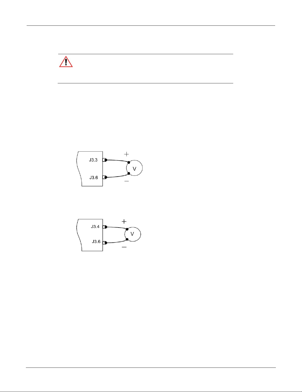
Series 2268 850 Watt DC Power Supplies Reference Manual Analog Programming & Isolated Analog Programming
Making ISOL Control Connec t ions
CAUTION: Equipment damage
Before making connections from external circuits to the Isolated Analog
Programming Connector, turn the front panel power switch to off and wait until
the front panel displays have gone out.
For most connectors and jumpers, use any suitable wire such as 22 AWG stranded wire. For
lowest noise performance, use shielded twisted pair wiring of 22 AWG. Use the shortest
leads possible. +5 V and +15 V Auxiliary Output reference to pin 2 and 6 (isolated common)
on the ISOL Connector.
ISOL Programming With Exte rnal Voltage Source
Figure 29: Programming Output Voltage using an Isolated External Voltage Source
ISOL Connector
Figure 30: Programming Output Current using an Isolated External Voltage Source
ISOL Connector
2268S-901-01 Rev. A / January 2015 89
Page 92

Analog Programming & Isolated Analog Programming Series 2268 850 Watt DC Power Supplies Reference Manual
Voltage-Controlled Vol t a ge IS O L Setup
Activating ISOL Programming Voltage Mode
To activate ISOL programming voltage mode with an external voltage source:
1. Turn the 9-position mode control to the VAP position or press the rotary
Adjust/Enter control if the mode control is already at the VAP position.
is displayed on the output voltage display.
2. Turn rotary Adjust/Enter control to select (voltage source from isolated
connector).
3. Press the rotary Adjust/Enter control to commit the selected mode. is
displayed on the output voltage display.
4. Select th e in pu t source level using the rotary Adjust/Enter control.
5. Once the desired level has been selected, press the rotary Adjust/ Enter control to
commit the change.
The display will return to the normal display.
Deactivating ISOL Voltage Mode
To deactivate the ISOL voltage mode:
1. Turn the 9-position mode control to the VAP position or press the rotary
Adjust/Enter control if the mode control is already at the VAP position.
2. is displayed on the output voltage display.
3. Turn the rotary Adjust/Enter control to select .
4. Press the rotary Adjust/Ente r control to commit the change. The display will return
to the normal display.
90 2268S-901-01 Rev. A / January 2015
Page 93

Series 2268 850 Watt DC Power Supplies Reference Manual Analog Programming & Isolated Analog Programming
Quick Ti p: Remote
The SCPI command for these instructions are:
|LOCal
Query for ISOL Voltage Input Level
To query for ISOL voltage input level from non-isolated input:
1. Turn the 9-position mode control to the VAP position or press the rotary
Adjust/Enter control if the control knob is already at the VAP position.
is displayed on the output voltage display.
2. If the mo de is currently then select any other ISOL mode. If this step is done,
be sure to restore the ISOL setting to when the operation is complete.
Otherwise, do not rotate the rotary Adjust/Enter control to keep the current ISOL
mode.
3. Press the rotary Adjust/Enter control to select the ISOL mode.
The output voltage display should r ead and the output current display will display
ISOL level.
4. Press the rotary Adjust/Enter control to return to normal mode.
5. If the ISOL mode was modified in step 2, execute the procedure to deactivate the
ISOL voltage mode.
Operation uses these
SCPI commands. See
page 101.
[:]SYSTem[<channel>]:REMote:SOURce[:VOLTage] <?
|AVOLtage|IAVoltage|ARESistive|IAResistive>
[:]SYSTem[<channel>]:COMMunicate:APRogram:LEVel [:VOLTage][:ISOLated]
[:]MEASure[<channel>][:SCALar]:APRogram[:VOLTage] :ISOlated[:DC]?
2268S-901-01 Rev. A / January 2015 91
Page 94

Analog Programming & Isolated Analog Programming Series 2268 850 Watt DC Power Supplies Reference Manual
Voltage-Controlled Current ISOL Setup
Activating ISOL Programming Current Mode
1. Turn the 9-position mode control to the CAP position or press the rotary
adjust/Enter control if the control knob is already at the CAP position.
is displayed on the output voltage display.
2. Turn the rotary Adjust/Enter control to select (voltage source from isolated
connector).
3. Press the rotary adjust/Enter control to commit the selected mode. is
displayed on the output voltage display.
4. Select the input source level using the rotary adjust/Enter control.
5. Once the desired level has been selected, press the rotary adjust/ Enter control to
commit the change.
The display will return to the normal display.
Deactivating ISOL Current Mode
To deactivate the ISOL current mode:
1. Turn the 9-position mode control to the VAP position or press the rotary
Adjust/Enter control if the control knob is already at the VAP position.
2. is displayed on the output voltage display.
3. Turn the rotary Adjust/Enter control to select .
4. Press the rotary Adjust/Ente r control to commit the change. The display will return
to the normal display.
92 2268S-901-01 Rev. A / January 2015
Page 95

Series 2268 850 Watt DC Power Supplies Reference Manual Analog Programming & Isolated Analog Programming
Quick Ti p: Remote
The SCPI command for these instructions are:
Query for ISOL Current Input Level
To query for ISOL current input level from non-isolated input:
1. Turn the 9-position mode control to the CAP position or press the rotary
Adjust/Enter control if the control knob is already at the CAP position.
is displayed on the output voltage display.
2. If the mo de is currently then select any other ISOL mode. If this step is done,
be sure to restore the ISOL setting to when the operation is complete.
Otherwise, do not rotate the rotary Adjust/Enter control to keep the current ISOL
mode.
3. Press the rotary adjust/Enter control to select the ISOL mode.
The output voltage display should r ead and the ou tpu t cu rrent d isp lay w ill d isp lay
ISOL level.
4. Press the rotary adjust/Enter control to return to normal mode.
5. If the ISOL mode was modified in step 2, execute the procedure to deactivate the
ISOL voltage mode.
operation uses these
SCPI commands. See
page 101.
[:]SYSTem[<channel>]:REMote:SOURce:CURRent: <?|LOCal
|AVOLtage|IAVoltage|ARESistive|IAResistive>
[:]SYSTem[<channel>]:COMMunicate:APRogram:LE Ve l:CURRent [:ISOLated]
[:]MEASure[<channel>][:SCALar]:APRogram:CURRent
:ISOlated[:DC]?
2268S-901-01 Rev. A / January 2015 93
Page 96

Analog Programming & Isolated Analog Programming Series 2268 850 Watt DC Power Supplies Reference Manual
ANALOG PROGRAMMING WITH EXTERNAL RESISTOR
Figure 31: Programming Output Voltage using an Isolated External Resistor
ISOL Connector
Figure 32: Programming Output Current using an Isolated External Resistor
ISOL Connector
94 2268S-901-01 Rev. A / January 2015
Page 97

Series 2268 850 Watt DC Power Supplies Reference Manual Analog Programming & Isolated Analog Programming
Resistive-Controlled Voltage ISOL Setup
Activating ISOL Programming Voltage Mode
To activate ISOL programming voltage mode using an external resistor:
1. Turn the 9-position mode control to the VAP position or press the rotary
adjust/Enter control if the control knob is already at the VAP position.
is displayed on the output voltage display.
2. Turn the rotary Adjust/Enter control to select (resistor source from isolated
connector).
3. Press the rotary adjust/Enter control to commit the selected mode. is
displayed on the output voltage display.
4. Select the input source level using the rotary adjust/Enter control.
5. Once the desired level has been selected, press the rotary Adjust/ Enter control to
commit the change.
The display will return to the normal display.
Deactivating ISOL Voltage Mode
To deactivate the ISOL voltage mode:
1. Turn the 9-position mode control to the VAP position or press the rotary
Adjust/Enter control if the control knob is already at the VAP position.
2. is displayed on the output voltage display.
3. Turn the rotary Adjust/Enter control to select .
4. Press the rotary adjust/Enter control to commit the change.
The display will return to t h e normal display.
2268S-901-01 Rev. A / January 2015 95
Page 98

Analog Programming & Isolated Analog Programming Series 2268 850 Watt DC Power Supplies Reference Manual
Quick Ti p: Remote
The SCPI command for these instructions are:
|LOCal
Query for ISOL Voltage Input Level
To query for ISOL voltage input level from non-isolated input:
1. Turn the 9-position mode control to the VAP position or press the rotary
Adjust/Enter control if the control knob is already at the VAP position.
is displayed on the output voltage display.
2. If the mo de is currently then select any other ISOL mode. If this step is done,
be sure to restore the ISOL setting to when the operation is complete.
Otherwise, do not rotate the rotary Adjust/Enter control to keep the current ISOL
mode.
3. Press the rotary adjust/Enter control to select the ISOL mode.
The output voltage display should r ead and the output current display will display
ISOL level.
4. Press the rotary adjust/Enter control to return to normal mode.
5. If the ISOL mode was modified in step 2, execute the procedure to deactivate the
ISOL voltage mode.
Operation uses these
SCPI commands. See
page 101.
[:]SYSTem[<channel>]:REMote:SOURce[:VOLTage] <?
|AVOLtage|IAVoltage|ARESistive|IAResistive>
[:]SYSTem[<channel>]:COMMunicate:APRogram:LEVel [:VOLTage][:ISOLated]
[:]MEASure[<channel>][:SCALar]:APRogram[:VOLTage]
:ISOlated[:DC]?
96 2268S-901-01 Rev. A / January 2015
Page 99

Series 2268 850 Watt DC Power Supplies Reference Manual Analog Programming & Isolated Analog Programming
Resistive-Controlled Current ISOL Setup
Activating ISOL Resistive-Controlled Current Setup
1. Turn the 9-position mode control to the CAP position or press the rotary
Adjust/Enter control if the control knob is already at the CAP position.
is displayed on the output voltage display.
2. Turn rotary Adjust/Enter control to select (voltage source from isolated
connector).
3. Press the rotary Adjust/Enter control to commit the selected mode. is
displayed on the output voltage display.
4. Select the input sourc e leve l using the rotary Ad just/Enter control.
5. Once the desired level has been selected, press the rotary Adjust/ Enter control to
commit the change.
The display will return to the normal display.
Deactivating ISOL Current Mode
To deactivate the ISOL current mode:
1. Turn the 9-position mode control to the CAP position or press the rotary
Adjust/Enter control if the control knob is already at the CAP position.
2. is displayed on the output voltage display.
3. Turn the rotary Adjust/Enter control to select .
4. Press the rotary Adjust/E nter con trol to co mm it the chang e. The di splay w ill return
to the normal display.
2268S-901-01 Rev. A / January 2015 97
Page 100

Analog Programming & Isolated Analog Programming Series 2268 850 Watt DC Power Supplies Reference Manual
Quick Ti p: Remote
The SCPI command for these instructions are:
Query for ISOL Current Input Level
To query for ISOL current input level from non-isolated input:
1. Turn the 9-position mode control to the CAP position or press the rotary
Adjust/Enter control if the control knob is already at the CAP position.
is displayed on the output voltage display.
2. If the mo de is currently then select any other ISOL mode. If this step is done,
be sure to restore the ISOL setting to when the operation is complete.
Otherwise, do not rotate the rotary Adjust/Enter control to keep the current ISOL
mode.
3. Press the rotary Adjust/Enter control to select the ISOL mode.
The output voltage display should r ead and the output current display will d ispla y
ISOL level.
4. Press the rotary Adjust/Enter control to return to normal mode.
5. If the ISOL mode was modified in step 2, execute the procedure to deactivate the
ISOL voltage mode.
operation uses these
SCPI commands. See
page 101.
[:]SYSTem[<channel>]:REMote:SOURce:CURRent <?|LOCal
|AVOLtage|IAVoltage|ARESistive|IAResistive>
[:]SYSTem[<channel>]:COMMunicate:APRogram: LEVel:CURRent [:ISOLated]
[:]MEASure[<channel>][:SCALar]:APRogram:CURRent
:ISOlated[:DC]?
98 2268S-901-01 Rev. A / January 2015
 Loading...