

Page 1

TM-09556A-12
MODEL 2246 MOD A
NSN 6625-01-275-4766
TAMCN A7061
Page 2

Page 3

T.O. 33A1-13-584-1
OPERATORS
TEK MANUAL
22461 Y,
2246 2R,
and
2246 Mod A
PORTABLE
OSCILLOSCOPES
OPERATORS
SN B100100
AND ABOVE
070-7061-00
Product Goup 46
Please Check for
CHANGE INFORMATION
at the Rear of This Manual
THIS MATERIEL MAY BE REPRODUCED BY OR FOR THE U.S. GOVERNMENT
PURSUANT TO THE COPYRIGHT LICENSE UNDER THE (DFAR) CLAUSE AT
S2.227-7013 (15 MAY 1987).
DISTRIBUTION STATEMENT - Distribution authorized to U.S. Government agencies
only for administrative or operational use, (effective date is date of this manual). Other
requests for this document must be referred to San Antonio ALC/MMEDT, Kelly AFB TX
78241-5000.
HANDLING AND DESTRUCTION NOTICE - Comply with distribution statement and
destroy by any method that will prevent disclosure of contents or reconstruction of the
document.
First Printing JUN 1988
Revised JUN 1989
Page 4

Copyright
cation may not be reproduced in any form without the written permission of
Tektronix, Inc.
Products of Tektronix, Inc. and its subsidiaries are covered by U.S. and
foreign patents and/or pending patents,
01988
Tektronix, Inc. All rights reserved. Contents of this publi-
TEKTRONIX, TEK, SCOPE-MOBILE and
of Tektronix, Inc.
Printed in U.S.A. Specification and price change privileges are reserved.
are registered trademarks
@
INSTRUMENT SERIAL NUMBERS
Each instrument has a serial number on a panel insert, tag, or stamped on
the chassis. The first number or letter designates the country of manufacture. The last five digits of the serial number are assigned sequentially and
are unique to each Instrument. Those manufactured in the United States
have six unique digits, The country of manufacture Is Identified as follows:
B000000
G100000
E200000
J300000
H700000
Tektronix, Inc., Beaverton, Oregon, U.S.A.
Tektronix Guernsey, Ltd., Channel Islands
Tektronix United Kingdom, Ltd., Marlow
Sony/Tektronix, Japan
Tektronix Holland, NV, Heerenveen, The Netherlands
HK00000
Hong Kong
Page 5

Repackaging for Shipment
Save the original shipping carton and packing material in case it is ever
necessary to reship the instrument by a commercial transport carrier. If
the original materials are unfit or not available, then repackage the instrument using the following procedure.
Use a corrugated cardboard shipping carton with a test strength of at
1.
least 275 pounds and an inside dimension at least six inches greater
than the instrument dimensions.
Enclose the following information: owner’s address, name and phone
2.
number of a contact person, type and serial number of the instrument,
reason for returning, and a complete description of the service
required.
Completely wrap the instrument with polyethylene sheeting or
3.
equivalent to protect the outside finish and keep harmful substances
out of the instrument.
Cushion instrument on all sides with three inches of padding material or
4.
urethane foam, tightly packed between the carton and the instrument.
Seal the shipping carton with an Industrial stapler or strapping tape.
5.
6.
If the instrument was NOT purchased under Air Force Contract No.
F41 608-88-D-0087, address the shipping carton to the nearest
Tektronix Service Center. Please include your own return address on
the shipping carton.
If purchased under Air Force Contract No. F41608-88-D-0087, this
instrument is warranted for 5 years in accordance with the terms of
said contract.
NOTE
Special Instructions for instruments purchased under Air Force
Contract No. F41 608-88-D-0087:
If the instrument IS still under warranty, contact your local Tektronix
Service Center for shipping instructions.
If the Instrument IS NOT under warranty, address the shipping
carton to the nearest Tektronix Service Center. Please Include your
own return address on the shipping carton.
Page 6

Page 7

Certificate of the Manufacturer/Importer
We hereby certify that the
OSCILLOSCOPES AND ALL INSTALLED OPTIONS
complies with the RF Interference Suppression requirements of
Amtsbl.-Vfg 1046/1984.
The German Postal Service was notified that the equipment is being
marketed.
The German Postal Service has the right to re-test the series and to
verify that it complies.
TEKTRONIX
2246 1Y AND 2246 MOD A
TEKTRONIX
Page 8
NOTICE to the user/operator:
The German Postal Service requires that Systems assembled by the
operator/user of this instrument must also comply with Postal
Regulation, Vfg. 1046/1984, Par. 2, Sect. 1.
NOTICE to the user/operator:
The German Postal Service requires that this equipment, when used in a
test setup, may only be operated if the requirements of Postal
Regulation, Vfg. 1046/1984, Par. 2, Sect. 1.7.1 are complied with.
Page 9

TABLE OF CONTENTS
Page
LIST OF ILLUSTRATIONS . . . . . . . . . . . . . . . . . . . . . . . . . . . . . . . .
LIST OF TAB LEA . . . . . . . . . . . . .
OPERATORS SAFETY SUMMARY . . . . . . . . . . . . . . . . . . . . . . . .
SECTION 1-INTRODUCTION
PRODUCT OVERVIEW . . . . . . . . . . . . . . . . . . . . . . . . . . . . . . . . . .
Description . . . . . . . . . . . . . . . . . . . . . . . . . . . . . . . . . . . . . . . . . .
Standard Accessories . . . . . . . . . . . . . . . . . . . . . . . . . .
PREPARATION FOR USE. . . . . . . . . . . . . . . . . . . . . . . .
Safety . . . . . . . . . . . . . . . . . . . . . . . . . . . . . . . . . . . . . . . . . . . . . . .
Line Fuse . . . . . . . . . . . . . . . . . . . . . . . . . . . . . . . . . . . . . . . . . . .
Line Voltage and Power Cord . . . . . . . . . . . . . . . . . . . . . . . . .
Instrument Cooling . . . . . . . . . . . . . . . . . . . . . . . . . . . . . . . . . . . . . . .
Start-Up . . . . . . . . . . . . . . . . . . . . . . . . . . . . . . . . . . . . . . . . .
Repackaging for Shipment . . . . . . . . . . . . . . . . . . . . . . . . . . . . . . .
SECTION 2-CONTROLS, CONNECTORS, AND INDICATORS
CRT, Power and Display.. . . . . . . . . . . . . . . . . . . . . . . . . . . . . .
Vertical . . . . . . . . . . . . . . . . . . . . . . . . . . . . . . . . . . . . . . . . . . . . . . .
Horizontal . . . . . . . . . . . . . . . . . . . . . . . . . . . . . . . . . . . . . . . .
Trigger . . . . . . . . . . . . . . . . . . . . . . . . . . . . . . . . . . . . . . . . . . . .
A Trigger Modes . . . . . . . . . . . . . . . . . . . . . . . . . . . . . . . . . . .
B Trigger Modes . . . . . . . . . . . . . . . . . . . . . . . . . . . . . . . . . . .
Rear Panel . . . . . . . . . . . . . . . . . . . . . . . . . . . . . . . . . . . . . . . . . . . . .
Menu System Controls . . . . . . . . . . . . . . . . . . . . . . . . . . . . . . . . .
. . . . . . . . . . . . . . . . . . . . .
vi
viii
ix
1-1
1-1
1-3
1-4
1-4
1-4
1-4
1-6
1-6
1-7
2-1
2-3
2-7
2-11
2-13
2-14
2-17
2-19
SECTION 3-OPERATORS FAMILIARIZATION
BASIC OPERATION . . . . . . . . . . . . . . . . . . . . . . . . . . . . . . . . . . . . .
Readout Display . . . . . . . . . . . . . . . . . . . . . . . . . . . . . . . . . . .
Graticule . . . . . . . . . . . . . . . . . . . . . . . . . . . . . . . . . . . . . . . . . . . . . .
2246 1Y and 2246 Mod A Operators
3-1
3-1
3-1
i
Page 10

Connecting Input Signals . . . . . . . . . . . . . . . . . . . . . . . . . . . . . . . . . .
Grounding . . . . . . . . . . . . . . . . . . . . . . . . . . . . . . . . .
Probes . . . . . . . . . . . . . . . . . . . . . . . . . . . . . . . . . . . . . . . . .
Coaxial Cables . . . . . . . . . . . . . . . . . . . .
External Triggering . . . . . . . . . . . . . . . . . . . . .
MENU SYSTEM OPERATION.. . . . . . . . . . . . . . . . . . . . . . . . . . . . .
Introduction . . . . . . . . . . . . . . . . . . . . . . .
Clearing the Menu and Cursors Display . . . . . . .
Setting Measurement Channel . . . . . . . . . . . .
Recalling the Last Measurement Mode . . . . . . . . .
Channel land Channel 2 Voltmeter . . . . . . . .
Voltmeter Measurements Page 1 . . . . . . . . . . . . . . . . . . . . . . .
Voltmeter Measurements Page 2, GATED Measurements
Cursors Measurements . . . . . . . . . . . . . . . .
Time Menus . . . . . . . . . . . . . . . .
Conditions for Cursors Display . . . . . . .
Measurement Cursors . . . . . . .
Track Trig Lvl Cursors.. . . . . . . . . . . . .
A
Track
Cursors. . . . . . . . . .
Behavior for Horizontal Mode Changes . . . . . . . . . . . .
Measurement Compatibility and Error Messages . . . . . . . . . . . .
Measurements in Single Sequence Mode . . . . . . . . . . . . .
Service Menu Features . . . . . . . . . . . . . . . .
Configure Menu. . . . . . . . . . . . . .
Self Cal Measurements . . . . . . . . . . . . . . . . . . . .
Internal Settings Menu . . . . . . . . . . . . . .
3-3
3-3
3-4
3-4
3-4
3-5
3-5
3-5
3-6
3-8
3-8
3-10
3-10
3-11
3-13
3-16
3-16
3-16
3-17
3-17
3-18
3-19
3-20
3-21
3-23
3-23
SECTION 4-OPERATOR CHECKS AND ADJUSTMENTS
Introduction . . . . . . . . . . . . . . . . . . . . . . . .
Initial Setup . . . . . . . . . . . . . . . . . . . . . . . . . . . . .
4-1
4-1
Trace Rotation Adjustment. . . . . . . . . . . . . . . 4-2
Probe Low-Frequency Compensation . . . . . . . . . .
Vertical Deflection Check.. . . . . . . . . .
4-3
4-4
Timing Checks . . . . . . . . . . . . . . . . . . . . . . . . . 4-5
ii
2246 1Y and 2246 Mod A Operators
Page 11

SECTION 5-BASIC APPLICATIONS
Introduction . . . . . . . . . . . . . . . . . . . . . . . . . . . . . . . . . . . . . . . . . . .
CH 1/CH 2 Voltmeter Measurements . . . . . . . . . . . . . . . . . . . . . . .
Peak Voltage Measurement.. . . . . . . . . . . . .
Gated Voltage Measurement. . . . . . . . . . . . . . . . . . . . . . . . . . . .
Voltage Measurement Cursors . . . . . . . . . . . . . . . . . . . . . . . . . . .
Voltage Difference . . . . . . . . . . . . . . . . . . .
Ground-Referenced Voltage . . . . . . . . . . . . . . . . . . . . . . . . .
Time Measurement Cursors. . . . . . . . . . . . . . . . . . . . . . . . . .
Time Difference . . . . . . . . . . . . . . . . . . . . . . . . . . . . . . . . . . . .
Period Measurement . . . . . . . . . . . . . . . . . . . . . . . . . . . . . . . . .
Frequency Measurement . . . . . . . . . . . . . . . . . . . . . . . . . . . . .
Rise-Time Measurements . . . . . . . . . . . . . .
Phase Measurements . . . . . . . . . . . . . . . . . . . . . . . . . . . . . . .
Time Delay Measurement.. . . . . . . . . . . . . . . . . . . . . . . . . .
Track Trigger Level Cursors . . . . . . . . . . . . . . .
Setting Trigger Level . . . . . . . . . . . . . . . . . . . . . . . . . . . . . . . .
Use of the Add Mode . . . . . . . . . . . . . . . . . . . . . . . . . . .
SECTION 6-PERFORMANCE CHARACTERISTICS
Introduction . . . . . . . . . . . . . . . . . . . . . . . . . . .
Recommended Calibration Schedule . . . . . . . . . . . . . . . . . . . . . . . .
SECTION 7-PERFORMANCE CHECK PROCEDURE
Introduction . . . . . . . . . . . . . . . . . . . . . . . .
Test Equipment Required.. . . . . . . . . . . . . . . . . . . . . . . . . . . . . . .
Performance Check Interval. . . . . . . . . . . . . . . . . . . .
Preparation . . . . . . . . . . . . . . . . . . . . . . . . . . . . . . . . . . . . . . . . . .
Index to Performance Check Procedure . . . . . . . . . . . . . .
DISPLAY . . . . . . . . . . . . . . . . . . . . . . . . . . . . . . . . . . . . . . . . . . . . .
Trace Rotation . . . . . . . . . . . . . . . . . . . . . . .
Geometry . . . . . . . . . . . . . . . . . . . . . . . . . . .
VERTICAL . . . . . . . . . . . . . . . . . . . . . . . . . . . . . . . . . . . . . . . . . . . .
input COUPLING Functional Check . . . . . . . . . . . . . .
CH 1 and CH 2 VOLTS/DIV Trace Shift . . . . . . . . . .
CH 3 and CH 4 VOLTS/DIV Trace Shift . . . . . . . . . . . . . . . . . .
CH 1 and CH 2 VAR VOLTS/DIV Trace Shift . . . . . . . . . . . . . . .
CH 1 and CH 2 Input Coupling Trace Shift . . . . . . . . . . .
CH 2 INVERT Trace Shift . . . . . . . . . . . . . . . . . .
5-1
5-1
5-2
5-4
5-6
5-6
5-8
5-10
5-10
5-11
5-11
5-12
5-14
5-17
5-19
5-23
5-24
6-1
6-1
7-1
7-1
7-1
7-2
7-6
7-8
7-8
7-9
7-10
7-10
7-11
7-12
7-12
7-13
7-13
2246 1Y and 2246 Mod A Operators
iii
Page 12

CH 1 and CH 2 VAR VOLTS/DIV Range . . . . . . . . . . . .
Low Frequency Linearity Check. . . . . . . . . . . . . . .
CH 1 and CH 2 Vertical Deflection Accuracy. . . . .
CH 3 and CH 4 Vertical Deflection Accuracy . . . . . . . .
ADD Mode and CH 2 INVERT Deflection Accuracy . . . . . . .
Vertical POSITION Range (all channels) . . . . . . . . . .
CH 1 to CH 2 Signal Delay Match . . . . . . . . . . . . .
CH 1 to CH 4 Signal Delay Match . . . . . . . . . . . . . . . . . . . . . .
CH 3 to CH 4 Signal Delay Match . . . . . . . . . . . .
Ch 1 and CH 2 Vertical Bandwidth . . . . . . . . . . . . . . . . . . . .
CH 3 and CH 4 Vertical Bandwidth . . . . . . . . .
Ch 1 and CH 2 Aberrations . . . . . . . . . . . . . . . . . . . . . . . . . .
SCOPE BW (Bandwidth Limit) Accuracy . . . . . . . . .
Common-mode Rejection Ratio . . . . . . . . . . . . .
Channel Isolation . . . . . . . . . . . . . . . . . . .
AC-Coupled Lower -3 dB Point . . . . . . . . . . . . . . . . . . . . . . . .
Vertical ALT and CHOP Modes . . . . . . . . . . . . . . . . . . . . . . . . .
BEAM FIND Functional Check . . . . . . . . . . . . . . . . . . . . . . . . .
A and B Trace Separation, . . . . . . . . . . . . . . . . . . . . . . . .
TRIGGERING . . . . . . . . . . . . . . . . . . . . . . . . . . .
500 Hz Trigger Sensitivity., . . . . . . . . . . . . . . . . . . . . . . . .
500 kHz Trigger Sensitivity. . . . . . . . . . . . . . . . . . . . . . . . . . . .
25 MHz Trigger Sensitivity. . . . . . . . . . . . . . . . . . . . . . . . . . . . .
100 MHz Trigger Sensitivity . . . . . . . . . . . . . . . . . . . . . . . . . . .
100 MHz NOISE REJ Trigger Sensitivity . . . . . . . . . . . .
Single Sweep Mode . . . . . . . . . . . . . . . . . . . . . . . . . . .
Trigger LEVEL Control Range . . . . . . . . . . . . . . . . . . . . . . . .
TV Field Trigger Sensitivity . . . . . . . . . . . . . . . . . . . . . . . . . . .
TV Line Trigger Sensitivity . . . . . . . . . . . . . . . . . . . . . . . . . . .
Line Trigger Functional Check . . . . . . . . . . . . . . . . . . . . . . . . . .
HORIZONTAL . . . . . . . . . . . . . . . . . . . . . . . . . . . . . . . . . . . . . . . .
A and B Sweep Length . . . . . . . . . . . . . . . . . . . . . . . . . .
Horizontal POSITION Range . . . . . . . . . . . . . . . . . . . . . . . .
VAR SEC/DIV Range . . . . . . . . . . . . . . . . . . . . . . . . . . . . . . .
Magnifier Registration.... . . . . . . . . . . . . . . . . . . . . . . . . . .
A and B Timing Accuracy and Linearity . . . . . . . . . . . . . . . . .
A and B Magnified Timing Accuracy and Linearity . . . . . . .
Delay Time Jitter...... . . . . . . . . . . . . . . . . . . . . . . . .
Delay Time Accuracy... . . . . . . . . . . . . . . . . . . . . . . . . . . .
Delay Time Position Range . . . . . . . . . . . . . . . . . . . . . . . . .
X-Axis Gain Accuracy . . . . . . . . . . . . . . . . . . . . . . . . . . . .
X-Y Phase Difference . . . . . . . . . . . . . . . . . . . . . . . . . . . . . . . .
X-Axis Bandwidth . . . . . . . . . . . . . . . . . . . . . . . . . . . . . . .
7-13
7-14
7-15
7-16
7-16
7-17
7-19
7-19
7-20
7-20
7-21
7-22
7-22
7-23
7-24
7-25
7-26
7-26
7-27
7-28
7-28
7-29
7-30
7-31
7-32
7-32
7-33
7-34
7-34
7-35
7-36
7-36
7-37
7-37
7-38
7-38
7-40
7-41
7-41
7-42
7-43
7-43
7-44
iv
2246 1Y and 2246 Mod A Operators
Page 13

TIME AND CURSORS MEASUREMENTS . . . . . . . . . . . . . .
l+ SEC+land ltl/SEC ~
Cursor Accuracy . . . . . . . . .
7-45
7-45
Delta Time Accuracy . . . . . . . . . . . . . . . . . . . . . . . . . . 7-46
ltPHASE +1
l+
VOLTS ~ Cursor Accuracy . . . . . . . . . . . . . . . . . . . . .
hvoLTs+curSOrAccuracy
Tracking Cursors Position Accuracy . . . . . . . . . . . . . . . . . 7-48
Cursor Accuracy . . . . . . . . . . . . . . . . . . . . .
. . . . . . . . . . . . . . .
7-47
7-47
7-48
CH 1/CH 2 VOLTMETER MEASUREMENTS . . . 7-50
DC Volts Accuracy . . . . . . . . . . . . . . . . . . . . . . . . . . . . . .
DC Volts Normal Mode Rejection Ratio . . . . .
7-50
7-51
+Peak, -Peak, Peak-to-Peak Voltage Accuracy . . . . . . . . . . . 7-52
25 MHz +Peak, -Peak, and Peak-to-Peak Volts Accuracy . .
7-53
100 MHz +Peak, -Peak, and Peak-to-Peak Volts Accuracy . 7-53
Gated Volts Accuracy . . . . . . . . . . . . . . . . . . . . . . . . . .
7-54
EXTERNAL Z-AXIS, PROBE ADJUST AND FACTORY
SETTINGS Functions . . . . . . . . . . . . . . . . . . . . . . . . . . . . . .
7-55
Check External Z-Axis Input . . . . . . . . . . . . . . . . . . . . . . . 7-55
PROBE ADJUST Output . . . . . . . . . . . . . . . . . . . . . . . . . . . . . . .
Run MAKE FACTORY SETTINGS Routine . . . . . . . . . . . . . . . .
7-56
7-56
SECTI0N 8-OPTIONS AND ACCESSORIES
Introduction. . . . . . . . . . . . . . . . . . . . . . . . . . . . . . . . . . . . . . . . . . .
Option 2R (Rackmount) . . . . . . . . . . . . . . . . . . . . . . . . . . . . .
Options A1-A5 Internatlonal Power Cords . . . . . . . . . . . . . . . .
Standard Accessories.. . . . . . . . . . . . . . . . . . . . . . . . . . . . . . . . .
Optional Accessories . . . . . . . . . . . . . . . . . . . . . . . . . . . . . . . . .
Instrument Enhancements. . . . . . . . . . . . . . . . . . . . . . . . . . .
Transportation Adds . . . . . . . . . . . . . . . . . . . . . . . .
Cameras, . . . . . . . . . . . . . . . . . . . . . . . . . . . . . . . . . . .
Probes . . . . . . . . . . . . . . . . . . . . . . . . . . . . . . . . . . . . . . . . . . .
Viewing Hoods . . . . . . . . . . . . . . . . . . . . . . . . . . . . . . . . . . .
8-1
8-1
8-1
8-2
8-3
8-3
8-3
8-3
8-3
8-3
APPENDIX A - FACTORY SETTINGS
APPENDIX B - 067-0557-00 CALIBRATION FIXTURE
2246 1Y and 2246 Mod A Operators
REV JUN 1989 v
Page 14

LIST OF ILLUSTRATIONS
Figure
1-1
The 2246A Oscilloscope . . . . . . . . . . . . . . . . . . . . . . . . . . . .
1-2
Optional power cords . . . . . . . . . . . . . . . . . . . . . . . . . .
2-1
CRT, power, and display controls . . . . . . . . . . . . . . . . . . .
2-2
CH 1 and CH 2 vertical controls and connectors . . . . . . . . . . . . .
2-3
Vertical connectors and CH 3 and CH 4 controls . . . . .
2-4
Horizontal controls and indicators . . . . . . . . . . . . . . . . . . .
2-5
Trigger controls and indicators . . . . . . . . . . . . . . . . . . . . .
2-6
Rear panel . . . . . . . . . . . . . . . . . . . . . . . . . . . . . . . . . . .
2-7
Menu controls . . . . . . . . . . . . . . . . . . . . . . . .
3-1
Readout display locations . . . . . . . . . . . . . . . . . . . . . . . . . .
3-2
Graticule measurement markings . . . . . . . . . . . . . . . . . . .
3-3
Voltmeter measurement channel menu . . . . . . . . .
3-4
Delay-Time/Delta-Time channel menu . . . . . . . . . . . . . .
3-5
Voltmeter and Gated Measmt menus . . . . . . . . . . . . . . .
3-6
Cursor Volts measurements menus . . . . . . . . . . . . . . . . .
3-7
Time measurement menu . . . . . . . . . . . . . . . . . . . . . . . . .
3-8
Service menu . . . . . . . . . . . . . . . . . . . . . . . . . . . . . . . . . . . .
3-9
Configure menu . . . . . . . . . . . . . . . . . . . . . . . . . . . . . . . .
3-10
Internal settings menu . . . . . . . . . . . . . . . . . . . . . . . . . . .
4-1
Probe compensation. . . . . . . . . . . . . . . . . . . . . . . .
5-1
+PEAK voltage measurement and tracking cursors .
5-2
Gated voltage measurement . . . . . . . . . . . . . . . . . . . . . . . .
5-3
Voltage difference measurement using cursors . . . . . . . . . . .
5-4
Voltage measurement . . . . . . . . . . . . . . . . . . . . . . . .
5-5
Period measurement . . . . . . . . . . . . . . . . . . . . . . .
5-6
Frequency measurement . . . . . . . . . . . . . . . . . . . . . . . . . .
5-7
Rise time measurement . . . . . . . . . . . . . . . . . . . . . . .
5-8
Making a phase difference measurement . . . . . . . . . . . .
5-9
Time difference between the two delays . . . . . . . .
5-10
A and B Track Trig Lvl cursors . . . . . . . . . . . . . . . . . . . . .
5-11
Setting a specific trigger level . . . . . . . . . . . . . . . . . . . . . .
Page
1-1
1-5
2-2
2-4
2-6
2-8
2-12
2-18
2-20
3-2
3-3
3-6
3-7
3-9
3-12
3-14
3-20
3-22
3-24
4-4
5-4
5-6
5-7
5-9
5-11
5-12
5-13
5-16
5-19
5-20
5-23
vi
2246 1Y and 2246 Mod A Operators
Page 15

5-12 Eliminating common-mode signals . . . . . . . . . . . 5-26
6-1
Maximum input voltage vs frequency derating curve for
the CH 1, CH 2, CH 3, and CH 4 input connectors 6-15
6-2 Dimensional drawing, standard cabinet . . . . . . . . . . .
6-22
6-3 Dimensional drawing, rackmount cabinet (2240 F1R) 6-23
2246 1Y and 2246 Mod A Operators
vii
Page 16

LIST OF TABLES
Table
2-1
VERT Trigger SOURCE . . . . . . . . . . . .
3-1
Behavior for Horizontal MODE Changes . . . . . . . . .
5-1
Trigger Cursor Channel . . . . . . . . . . . . ..
6-1
Electrical Characteristics.. . . . . . . . . . . . . . . . .
6-2
Environmental Characteristics . . . . . . . . . . . .
6-3
Mechanical Characteristics. . . . . . . . . . . . .
7-1
Test Equipment Required . . . . . . . . . . . . . . .
7-2
Signal-to-Graticule Accuracy . . . . . . . . . . . .
7-3
Settings for Timing Accuracy Checks . . . . . .
7-4
Delay Time Accuracy . . . . . . . . . . . . . . . .. . .
Factory Settings . . . . . . . . . . . . . . . . . . ..
A-1
Page
2-16
3-18
5-22
6-2
6-16
6-19
7-3
7-15
7-38
7-42
A-1
viii
2246 1Y and 2246 Mod A Operators
Page 17
OPERATORS SAFETY SUMMARY
The safety information in this summary is for operating personnel.
Warnings and cautions will also be found throughout the manual where
they apply.
Terms in this Manual
CAUTION statements identify
damage to the equipment or other property.
WARNING statements identify conditions or practices that could result in
personal injury or loss of life.
conditions or practices that could result in
Terms as Marked on Equipment
CAUTION indicates a personal injury hazard not immediately accessible as
one reads the markings, or a hazard to property, including the equipment
itself.
DANGER indicates a personal injury hazard immediately accessible as one
reads the marking.
Symbols in this Manual
This symbol indicates where applicable
A
cautionary or other information is to
be found. For maximum input voltage
see Table 6-1.
Symbols as Marked on Equipment
%
&_..
—
o
DANGER—High voltage.
Protective ground (earth) terminal.
A
2246 1Y and 2246 Mod A Operators
ATTENTION—Refer to manual.
ix
Page 18

Power Source
This product is intended to operate from a power source that does not apply more than 250 V rms between the supply conductors or between either
supply conductor and ground. A protective ground connection, by way of
the grounding conductor in the power cord, is essential for safe operation.
Grounding the Product
This product is grounded through the grounding conductor of the power
cord. To avoid electrical shock, plug the power cord into a properly wired
receptacle before making any connections to the product input or output
terminals. A protective ground connection, by way of the grounding con-
ductor in the power cord, is essential for safe operation.
Danger Arising From Loss of Ground
Upon loss of the protective-ground connection, all accessible conductive
parts, including knobs and controls that may appear to be insulating, can
render an electric shock.
Use the Proper Power Cord
Use only the power cord and connector specified for your product.
The power cord must be in good condition.
Read Section 1 for power-cord and connector information,
Use the Proper Fuse
To avoid fire hazard, use only a fuse of the correct type, voltage rating and
current rating as specified on the back of your product and in Table 6-1.
Do Not Operate in an Explosive Atmosphere
To avoid explosion, do not operate this product in an explosive atmosphere.
x
2246 1Y and 2246 Mod A Operators
Page 19

Do Not Remove Covers or Panels
(Excluding Front Panel Cover)
To avoid personal injury, do not remove the product covers or panels. Do
not operate the product without the covers and panels properly installed.
2246 1Y and 2246 Mod A Operators
REV JUN 1989
xi
Page 20

Page 21

SECTION 1
INTRODUCTION
2246 1Y and 2246 Mod A
Page 22

Page 23
Introduction
PRODUCT OVERVIEW
Description
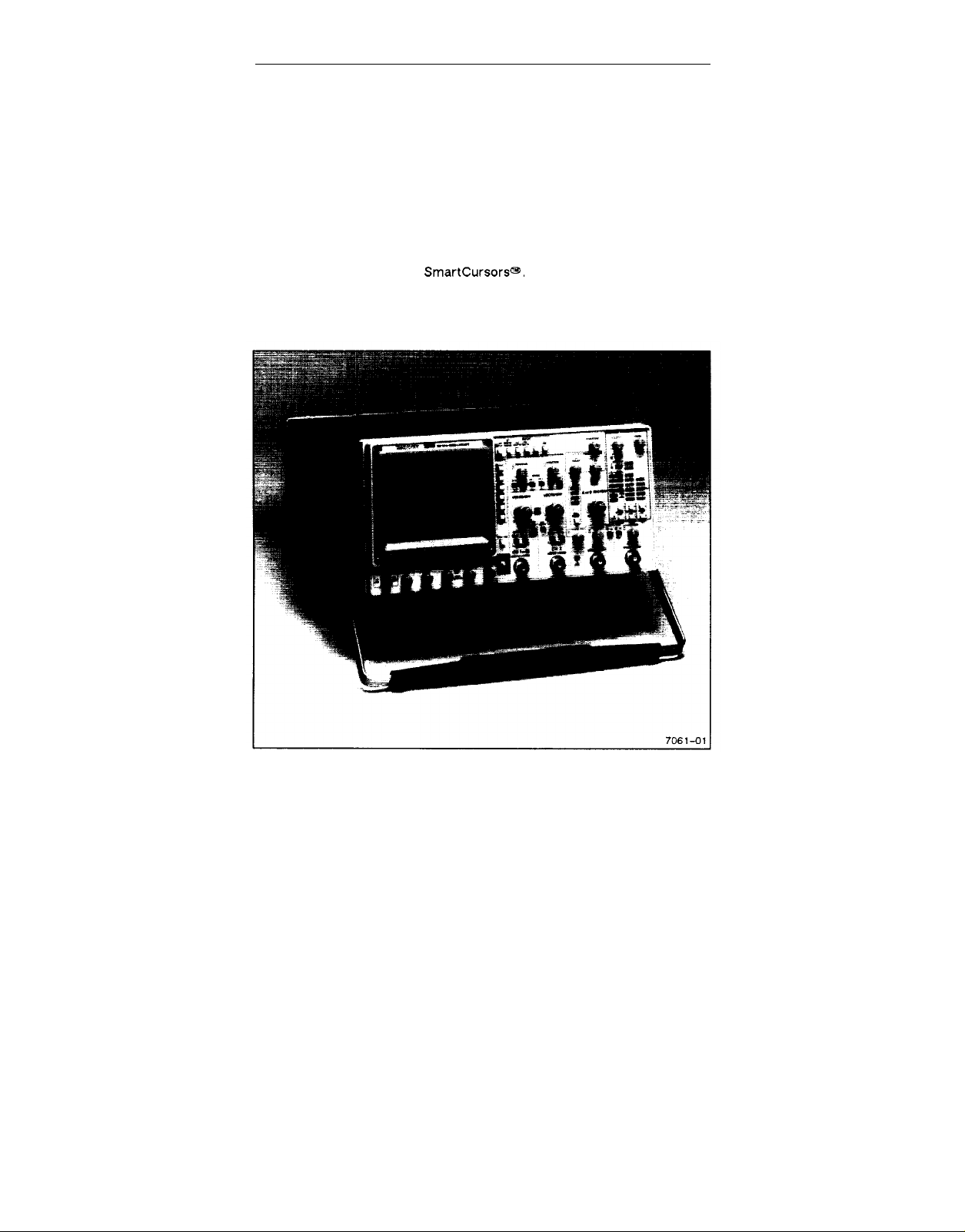
The 2246 1Y and 2246 Mod A are 100 MHz, four-channel, dual-sweep,
portable oscilloscopes for general-purpose use (Figure 1-1). A
microprocessor-based operating system controls most of the functions in
the instruments, including a fully Integrated menu-driven voltage and time
measurement system with
provides for configuring of certain menu and readout displays, internal
calibration, and servicing diagnostics.
SmartCursors@. A menu-driven service mode
Figure 1-1. The 2246 1Y and 2246 Mod A Oscilloscope.
2246 1Y and 2246 Mod A Operators
1-1
Page 24

Introduction
The vertical deflection system has four input channels. Two channels have
11 basic deflection factors from 2 mV to 5 V per division, and two channels
have two basic deflection factors of 0.1 V and 0.5 V per division. Basic
deflection factors can be extended with attenuator probes. VOLTS/DIV
readouts are switched to display the correct vertical scale factors when
properly coded probes are connected to the vertical input connectors.
The horizontal deflection system provides single, dual, or delayed sweeps
from 0.5 s to 20 ns per division (delayed sweep, 5 ms to 20 ns per division).
The trigger system provides stable triggering over the full bandwidth of the
vertical deflection system.
Alphanumeric crt readouts of the vertical and horizontal scale factors are
displayed at the bottom of the screen. On-screen vertical and horizontal
cursors provide accurate voltage, time, frequency, and phase measure-
ments; measurement values are displayed at the top of the crt.
The measurement features include voltage measurements for +Peak,
-Peak, Peak-to-Peak, and average DC, or positionable cursors for
measuring voltage difference, time difference, frequency, and phase.
SmartCursors@ that visually track voltage measurements, trigger levels,
and ground can be placed on displayed waveforms. Delay-time and deltadelay measurements for time, frequency, and phase are available in ALT
and B Horizontal Modes.
1-2
2246 1Y and 2246 Mod A Operators
Page 25

Introduction
Standard Accessories
The following Items are standard accessories shipped with the 2246 1Y and
2246 Mod A instrument:
2 Probes, 10X, 2 meter, with accessories
1 Probe, 1X, 2 meter, with accessories
1 Power cord
1 Power cord clamp
1 CRT implosion shield, blue plastic (installed)
1 Fuse, 2A, 250 V, slow-blow
1 Attaching accessory pouch
1 Accessory pouch, ziploc
1 Front Cover
The following Items are standard accessories shipped with the 2246 1Y
instrument:
2 Operators manuals
2 Service manuals
2 Reference guides
The following Items are standard accessories shipped with the 2246 Mod A
instrument:
1 Operators manual
1 Reference guide
See Section 8, “Options and Accessories” for part numbers and further
information about standard accessories and a list of the recommended
optional accessories. For more information on accessories and ordering
assistance, contact your Tektronix representative or local Tektronix Field
Office.
2246 1Y and 2246 Mod A Operators
REV JUN 1989
1-3
Page 26

Introduction
PREPARATION FOR USE
Safety
Refer to the Operators Safety Summary at the front of this manual for
power source, grounding, and other safety information about the use of the
instrument. Before connecting the 2246 1Y and 2246 Mod A to a power
source, read this section and the Safety Summary.
Line Fuse
This instrument can be damaged if the wrong line fuse is
installed.
Verify the proper value of the power-input fuse with the following
procedure,
1.
Press in the fuse-holder cap and release it with a slight counterclockwise rotation,
2. Pull the cap (with the attached fuse inside) out of the fuse holder.
3. Verify proper fuse value.
4.
Install the proper fuse and reinstall the fuse-holder cap.
Line Voltage and Power Cord
The 2246 1Y and 2246 Mod A operates on line voltages from 90 to 250 V
with line frequencies ranging from 48 to 440 Hz. No line voltage selecting is
necessary. Instruments are shipped with the power cord that was
requested on the order. The power cord must match the power-source
outlet; if it does not, contact your Tektronix representative or local
Tektronix Field Office. See Figure 1-2 for optional power cords available.
For electrical-shock protection, insert this plug into a powersource outlet that has a properly grounded protective-ground
contact.
1-4
2246 1Y and 2246 Mod A Operators
Page 27

Introduction
Figure 1-2. Optional power cords.
2246 1Y and 2246 Mod A Operators
1-5
Page 28

Introduction
The detachable three-wire power cord has a three-contact plug for connection to the power source and the protective ground. The power cord is
held to the rear panel by a clamp. The protective ground contact on the
plug connects (through the power cord protective-ground conductor) to
the accessible metal parts of the instrument.
Instrument Cooling
To prevent instrument damage from overheated components, make sure
the internal airflow is not blocked. Before turning on the power, check that
the ventilation holes on the bottom and side of the cabinet are not covered.
Start-up
At power on, the instrument does a self-diagnostic check. If the instrument
does not turn on and operate normally, turn power off then on again. If the
instrument still does not turn on properly, refer the instrument to a qualified
service person. TRIGGER MODE LEDs may be flashing to indicate the circuit location of a start–up error; you should report this information to the
service person.
When the instrument is turned on, a self-cal routine may run to set the
voltage- and timing-measurement constants. The power-on self cal runs
only if the stored constants have been lost, possibly due to a dead memory
back-up battery. The following warning message will be displayed for 5
seconds: “WARNING PROBABLE BATTERY FAILURE TURN OFF AND ON
TO VERIFY”. If the message reappears after having turned the power off
and on, have the battery checked and/or replaced by a qualified service
person. The instrument can still be used for accurate measurements by
running the SELF CAL MEASUREMENTS routine from the SERVICE MENU
after the instrument has warmed up for at least 20 minutes.
To run the SELF CAL MEASUREMENTS routine, press the top and bottom
menu-item select buttons. Press down-arrow button to underline SELF
CAL MEASUREMENTS. Press RUN to start the routine, then QUIT or
CLEAR DISPLAY to return to the normal oscilloscope mode.
1-6
2246 1Y and 2246 Mod A Operators
Page 29

Introduction
Repackaging for Shipment
Save the original shipping carton and packing material in case it is ever
necessary to reship the instrument by a commercial transport carrier. If
the original materials are unfit or not available, then repackage the instrument using the following procedure.
Use a corrugated cardboard shipping carton with a test strength of at
1.
least 275 pounds and an inside dimension at least six inches greater
than the instrument dimensions.
Enclose the following information: owner’s address, name and phone
2.
number of a contact person, type and serial number of the instrument,
reason for returning, and a complete description of the service
required.
Completely wrap the instrument with polyethylene sheeting or equiva-
3.
lent to protect the outside finish and keep harmful substances out of
the instrument.
Cushion instrument on all sides with three inches of padding material or
4.
urethane foam, tightly packed between the carton and the instrument.
Seal the shipping carton with an industrial stapler or strapping tape.
5.
6.
If the Instrument was NOT purchased under Air Force Contract No.
F41608-88-D-008, address the shipping carton to the nearest
Tektronix Service Center. Please include your own return address on
the shipping carton.
NOTE
Special instructions for instruments purchased under Air Force
Contract No. F41608-88-D-0087:
If the instrument IS under warranty, contact your local Tektronix
Service Center for shipping instructions.
If the instrument IS NOT under warranty, address the shipping carton to the nearest Tektronix Service Center. Please include your own
return address on the shipping carton.
2246 1Y and 2246 Mod A Operators
REV AUG 1988
1-7
Page 30

Page 31

SECTION 2
CONTROLS,
CONNECTORS,
AND INDICATORS
2246 1Y and 2246 Mod A
Page 32

Page 33

Controls, Connectors, and Indicators
CRT, Power, and Display
Refer to Figure 2-1 for location of items 1 through 9.
POWER Switch–Turns on or off instrument power. Press for ON or
OFF.
At least one VERTICAL MODE button will light when the power is
turned on. The front-panel setup existing when the power is turned off
will return when the power is turned on again.
A INTEN Control–Adjusts the brightness of the A trace.
B INTEN Control–Adjusts the brightness of the B Delayed sweep
trace and the intensified zone on the A trace.
FOCUS Control-Adjusts the focus of the crt displays (traces,
readout, and cursors).
TRACE ROTATION Control–Aligns the crt trace with the horizontal
graticule lines. This is a screwdriver adjustment.
READOUT Control–Adjusts the brightness of the crt readout display
(includes all alphanumerics and cursors).
SCALE ILLUM Control–Adjusts
graticule.
NOTE
Life of the graticule illumination lamps can be increased by
setting the SCALE ILLUM control for the minimum intensity
needed for viewing, and turning off scale illumination when
not needed.
BEAM FIND Button–Locates off-screen and overscanned displays
when the button is held in. Limits the vertical and horizontal deflection
within the display area and unblanks the CRT.
2246 1Y and 2246 Mod A Operators
the illumination level of the
2-1
Page 34

Controls, Connectors, and Indicators
Figure 2-1. CRT, power, and display controls.
CRT–Displays waveforms and readouts in an 80 mm vertical by 100
mm horizontal graticule area.
Internal graticule lines provide parallax-free viewing of trace and
graticule lines. 0%, 10%, 90% and 100% points marked at the left
edge of the graticule aid in making rise- and fall-time measurements.
2-2
2246 Y and 2246 Mod A Operators
Page 35

Controls, Connectors, and Indicators
Vertical
Refer to Figure 2-2 for location of items 10 through 17.
CH 1 and CH 2 POSITION Controls—Adjust vertical position of the
Channel 1 and Channel 2 waveform displays.
MODE Buttons–Select the vertical channels for display (CH 1, ADD
channels 1 and 2, CH 2, CH 3, and CH 4). The CHOP/ALT MODE
button selects method for switching input channels on the display
(chopped or alternating).
Except for CHOP/ALT modes, pressing an unlit mode button turns on
the mode, and pressing a lit button turns off the mode. CHOP is
selected when the CHOP/ALT button is lit; ALT is selected when the
button is not lit.
CH 1, CH 2, CH 3, and CH 4-Select vertical channels for display.
At least one of the channels or ADD is always on and cannot be turned
off until another channel is first turned on.
CHOP/ALT-In the CHOP mode the display chops between selected
input channels at a rate of about 625 kHz. In the ALT mode, the
selected channels are displayed in sequence (alternating at the end of
each sweep).
ADD—Displays the algebraic sum of the Channel 1 and Channel 2
input signals. The ADD display is in addition to any other selected
channel displays. In the ADD mode, a plus sign (+) is displayed
between the Channel 1 and Channel 2 VOLTS/DIV readouts.
NOTE
In ADD mode when AUTO LEVEL TRIGGER MODE or
CHOP VERTICAL MODE is selected, the algebraic sum of
Channel 1 and Channel 2 displays provides the internal signal source for the trigger system when the trigger source is
VERT.
12
Channel 1 and Channel 2 VOLTS/DIV Switches–Select cali-
o
brated deflection factors for Channel 1 and Channel 2 from 2 mV per
division to 5 V per division in a 1-2-5 sequence of 11 steps.
2246 1Y and 2246 Mod A Operators
2-3
Page 36

Controls, Connectors, and Indicators
Figure 2-2. CH 1 and CH 2 vertical controls and indicators.
The switches are detented, continuous-rotation controls with no end
stops. The VOLTS/DIV readouts reflect attenuation factors of coded
attenuator probes connected to the vertical inputs.
CH 1 AND CH 2 VOLTS/DIV VAR Controls–Allows the CH 1 and
CH 2 vertical deflection factors to be increased up to at least 2.5
times.
2-4
2246 Y and 2246 Mod A Operators
Page 37

Controls, Connectors, and Indicators
Vertical deflection factors are greater than the VOLTS/DIV switch
setting when the UNCAL indicator is lit and a greater-than symbol (>)
is displayed to the left of the associated VOLTS/DIV readout.
UNCAL Indicator-Lights when either CH 1 or CH 2 VOLTS/DIV settings are uncalibrated (variable function in effect).
15
SCOPE BW Button–Reduces the bandwidth of the vertical deflec-
o
tion system to 20 MHz when the button is lit. The full vertical deflection
bandwidth is available when the SCOPE BW button is not lit.
16
CH 2 INVERT Button-Inverts the Channel 2 input signal when the
o
INVERT button is lit.
The Channel 2 input signal in ADD mode and the Channel 2 trigger
signal pickoff are also inverted. A down-arrow symbol is displayed
between the Channel 1 and Channel 2 VOLTS/DIV readout when the
INVERT mode is on.
17
COUPLING Buttons–Select the method of coupling input signals to
o
the Channel 1 and Channel 2 attenuators.
GND-Disconnects the Input signal and grounds the input of the
associated vertical attenuator to provide a zero (ground) reference
voltage display.
The COUPLING switch is in the ground position when the AC and the
*
DC buttons are not lit. A ground symbol (
of the associated VOLTS/DIV readout. The ground symbol is also
displayed after the value readout of any of the VOLTMETER
measurements.
AC-Capacitively couples the input signal to the vertical attenuator
when the AC button is lit.
Turning on AC Coupling turns off DC Coupling. AC Coupling blocks the
dc component of the input signal. The lower -3 dB frequency limit is
10 Hz or less when using either a 1X probe or properly terminated
coaxial cable; it is 1 Hz or less using a compensated 10X probe. With
AC Coupling selected, an AC symbol
the associated VOLTS/DIV readout. An ac symbol is also displayed
after the value readout of any Peak or Peak-to-Peak voltage
measurement.
2246 1Y and 2246 Mod A Operators
) is displayed to the right
(~]
is displayed to the right of
2-5
Page 38

Controls, Connectors. and Indicators
NOTE
When AC Coupling is selected for DC voltmeter measurements an error message
displayed.
DC—Couples dc and all frequency components of the input signal to
the vertical attenuator when the DC button is lit.
Turning on DC coupling turns off AC coupling. With DC Coupling
selected, a DC symbol (
ated VOLTS/DIV readout. Input resistance Is 1
Refer to Figure 2-3 for location of items 18 through 23
@
CH 1 OR X and CH 2 Input Connectors-Connect signals to the
–
inputs of Channel 1 and Channel 2 vertical attenuators.
Input connectors are BNC type with an outer contact ring for recognizing attenuation factors of coded attenuator probes. A signal connected to the CH 1 OR X input connector produces the horizontal
deflection (X-Axis) in the X-Y horizontal mode. Any of the vertical
signal channels or ADD can provide vertical deflection (Y-Axis) for an
X-Y display.
"SELECT DC COUPLING” is
=.
) is displayed to the right of the associ-
M~
to ground.
2-6
Figure 2-3. Vertical connectors and CH 3 and
CH 4 controls.
2246 Y and 2246 Mod A Operators
Page 39

Controls, Connectors, and Indicators
PROBE ADJUST Connector—Outputs a 0.5 V square-wave signal
(at about 1 kHz) for compensating voltage probes and checking the
vertical deflection accuracy.
Auxiliary Ground Jack—Provides an auxiliary chassis ground con-
nection (banana jack) between the equipment under test and the 2246
1Y or 2246 Mod A.
Channel 3 and Channel 4 POSITION Controls—Adjust vertical
position of Channel 3 and Channel 4 signal displays.
22
Channel 3 and Channel 4 VOLTS/DIV Switches–Select two basic
o
deflection factors for Channel 3 and Channel 4, 0.5 volt/division (but-
ton lit) or 0.1 volt/division (button not lit).
The VOLTS/DIV switch setting displayed in the crt readout reflects
the attenuation factor of coded attenuator probes that are connected
to the vertical inputs.
23
CH 3 and CH 4 Input Connectors–Connect signals to the inputs of
o
the Channel 3 and Channel 4 vertical attenuators. Input coupling is dc
only.
The input connectors are BNC with probe-coding ring contacts (the
same as Channel 1 and Channel 2). The limited choice of deflection
factors for the Channel 3 and Channel 4 inputs makes them useful for
digital and trigger signals.
Horizontal
Refer to Figure 2-4 for location of items 24 through 31.
24
POSITION Control–Adjusts the horizontal position of the waveform
0
displays on the crt.
25
X10 MAG Switch–Magnifies the normal sweep by a factor of 10 and
o
extends the fastest sweep speed to 2 ns per division. The center
portion of an unmagnified sweep display will be within 0.5 division of
the center of a magnified sweep display. No action occurs in X-Y
mode.
When X10 MAG is on, a X10 symbol is displayed next to the SEC/DIV
readouts. The readouts reflect correct display sweep speeds for the
X10 MAG displays and the unmagnified displays.
2246 1Y and 2246 Mod A Operators
2-7
Page 40

Controls, Connectors, and Indicators
Figure 2-4. Horizontal controls and indicators.
MODE Buttons (Up-Arrow and Down-Arrow) and IndicatorsSelect the operating mode of the horizontal deflection system. Pressing the Up-/Down-Arrow buttons selects the horizontal deflection
mode as shown by the MODE lights. Not all Menu Measurement
modes are compatible with all horizontal deflection modes. See
Table 3-1, Behavior for Horizontal MODE Changes, in Section 3.
A—Selects A sweep horizontal deflection. The A sweep speed is
determined by the A SEC/DIV switch setting as displayed in the crt
2-8 2246 Y and 2246 Mod A Operators
Page 41

Controls, Connectors, and Indicators
readout. Whenever A MODE is selected, the A/B SELECT switch is
set to A Trigger.
ALT-Alternates between A sweep (with an intensified zone representing B sweep) and B delayed sweep. Both A and B SEC/DIV switch
settings are displayed in the crt readout, but only the B can be
adjusted. Whenever ALT MODE is selected, the A/B SELECT switch
is set to B Trigger.
The B sweep speed cannot be set slower than the A sweep speed;
attempting to do so forces the A sweep speed to follow the B sweep
speed. To increase the A sweep speed in the ALT MODE, set the
Horizontal MODE to A, adjust the SEC/DIV switch to a faster A sweep
setting, and reset the Horizontal MODE switch to ALT. The B sweep
speed and the length of the intensified zone are determined by the B
SEC/DIV switch setting.
B—Select B sweep horizontal deflection. The B sweep speed is
determined by the B SEC/DIV switch setting as displayed in the crt
readout. Whenever B MODE is selected, the A/B SELECT switch is
set to B Trigger.
The start of the B sweep in RUNS AFTER mode (or the arming of the
B Trigger in any triggered mode) is delayed from the start of the A
l+-
sweep by a time determined by the setting of the
control. The B SEC/DIV switch setting and the Delay Time Position
setting are displayed In the crt readout. A greater-than sign (>) is
displayed in front of the Delay Time readout if the B Trigger MODE is
not RUNS AFTER,
OR DELAY
X-Y—The signal applied to CH 1 OR X input connector produces the
horizontal (X-Axis) deflection. Signals applied to any vertical input
connector or ADD may be selected to provide the vertical deflection
(Y-Axis).
The X-Y displays are horizontally positioned by the Horizontal
POSITION control and vertically positioned by the associated vertical
channel POSITION control.
27
A AND B SEC/DIV Switch–Selects the horizontal deflection rate
o
(sweep speed) for both the A sweep and the B sweep in a 1-2-5
sequence. Calibrated sweep speeds are obtained with the A and B
SEC/DIV VAR control in the detent (fully clockwise) position. The A
SEC/DIV switch setting is set only from the A Horizontal MODE and
the B SEC/DIV switch is set only from the ALT or B Horizontal MODE.
2246 1Y and 2246 Mod A Operators
2-9
Page 42

Controls, Connectors, and Indicators
NOTE
The B sweep speed can never be slower than the A sweep
speed. When the two sweep speeds are the same, they are
“ locked.” At this point A will follow B to slower SEC/D/V
settings (in ALT or B) and B will follow A to faster settings
(in A).
A SEC/DIV-The calibrated A sweep speed is selected only in A Horizontal MODE from 0.5 s per division to 20 ns per division (X10 MAG
off) .
B SEC/DIV-The calibrated B sweep speed is selected either in ALT
or B Horizontal MODE from 5 ms per division to 20 ns per division (X10
MAG off).
28
A and B SEC/DIV VAR Control–Provides continuously variable,
o
uncalibrated A and B sweep speeds to at least 2.5 times slower than
the calibrated SEC/DIV setting.
The VAR control extends the slowest A sweep speed to at least 1.25
sec per division. The UNCAL indicator is lit and a greater-than sign
(>) is displayed before each SEC/DIV readout value when the sweep
speeds are greater than the SEC/DIV settings.
29
CURSORS/TIME POSITION Controls–Sets the reference and
o
delta cursors on the display.
NOTE
The reference and delta cursors will only track together as
long as the reference delay plus the delta delay is less than
10 times the A SEC/DIV setting (10 horizontal graticule
divisions). The cursors cannot be positioned left of the 1st
or right of the 11th vertical graticule lines
1+
OR
DELAY—This control has the following functions:
1.
Positions the reference and delta cursors together in a cursor
measurement mode (volts or time, A Horizontal MODE).
2.
Positions the reference and delta delay together in the TIME
measurement mode in the ALT or B Horizontal MODE.
2-10
2246 Y and 2246 Mod A Operators
Page 43

Controls, Connectors, and Indicators
Sets the B sweep delay time in the ALT or B Horizontal Mode in
3.
DELAY measurement mode.
4.
Positions the intensified zone for GATED VOLTMETER
measurements.
.
This control has the following functions:
-4
Positions the delta cursor in the cursor measurement mode.
1.
2.
Sets the B sweep delta delay in TIME measurement mode
when in the ALT or B Horizontal Mode.
3.
Sets the width of the intensified zone for GATED VOLTMETER
measurements.
UNCAL Indicator-Lights when the A AND B SEC/DIV settings are
uncalibrated (variable function in effect).
TRACE SEP Control—Positions the B sweep trace vertically with
respect to the A sweep trace when ALT Horizontal MODE is selected.
Trigger
Refer to Figure 2-5 for location of items 32
A/B SELECT Button—Directs the MODE, SOURCE, CPLG, SLOPE,
32
0
and LEVEL controls and Trigger lights (TRIG’D and READY) to either
the A or B Trigger system (A, when lit; B, when not lit)
Either A or B trigger can be selected for any Horizontal MODE; how-
ever, A/B SELECT is preset to A when A Horizontal MODE is
selected, and B when ALT or B Horizontal MODE is selected. No
change occurs when switching from B to X-Y Horizontal MODE.
33
SLOPE Button–Selects the slope (positive- or negative-going) of
o
the trigger source signal that triggers either the A sweep or the B
sweep. (Button lit = positive-going; button not lit = negative-going.)
34
HOLDOFF Control—Varies holdoff time between the end of one
o
A sweep and the start of the next A sweep.
2246 1Y and 2246 Mod A Operators
through 38.
2-17
Page 44

Controls, Connectors, and Indicators
Figure 2-5. Trigger controls and indicators.
The HOLDOFF control can increase the minimum holdoff time by at
least 10 times. Adjusting this control can Improve triggering stability of
aperiodic signals (i.e., complex digital waveforms).
35
LEVEL Control–Sets the amplitude level on the trigger signal at
o
which either the A or B sweep is triggered.
Adjusting the LEVEL control to either end of its range, in the AUTO
LEVEL trigger mode, resets the limits of the Trigger LEVEL control
range to the peak-to-peak amplitude of the trigger source signal.
2-12
2246 Y and 2246 Mod A Operators
Page 45

Controls, Connectors, and Indicators
36
MODE Buttons (Up- and Down-Arrows) and Indicators-Select
o
the operating modes of the A and B trigger systems. Pressing the
Up-/Down-Arrow buttons selects the operating modes as shown by
the TRIGGER MODE lights.
Selections available for the A Trigger (A/B SELECT button lit) are:
AUTO LEVEL, AUTO, NORM, TV LINE, TV FIELD, and SGL SEQ.
Selections for the B Trigger (A/B SELECT button not lit) are: AUTO
LEVEL, RUNS AFTER, NORM, TV LINE FROM A SOURCE.
A Trigger Modes
AUTO LEVEL—Automatically sets the range of the Trigger LEVEL
control to the peak-to-peak limits of an adequate A Trigger source
signal and triggers the sweep.
Autoleveling is repeated if triggering is lost. If the TRIGGER LEVEL
control is rotated to either end stop, or if AUTO LEVEL TRIGGER
MODE is selected again. AUTO LEVEL mode is useful for quickly
locating and maintaining an appropriate triggering level.
NOTE
The A sweep free-runs to produce a baseline trace when
the A trigger source signal amplitude is too low or the
frequency is below 10 Hz. Switch to NORM triggering if the
repetition rate is too slow for autoleveling
AUTO-Triggers the same as the NORM Trigger MODE when an adequate trigger signal is applied. However, the A sweep free-runs to
display a baseline trace when there is no trigger signal or the
frequency Is below 10 Hz. The set triggering level changes only when
the TRIGGER LEVEL control is adjusted to a new level setting.
NORM—Triggers the A sweep when the A Trigger LEVEL control is
set within the peak-to-peak limits of an adequate trigger signal. When
the A sweep is not triggered, no baseline trace is displayed.
TV LINE—Starts the A sweep at the beginning of a video signal line.
SLOPE polarity must match the composite sync polarity (i.e.,
2246 1Y and 2246 Mod A Operators
J
2-13
Page 46

Controls, Connectors, and Indicators
SLOPE for positive sync) to obtain TV LINE triggering on the horizontal sync pulse.
TV FIELD-Starts the A sweep at the beginning of a video signal field.
SLOPE polarity must match the composite sync polarity to obtain TV
FIELD triggering.
SGL SEQ (Single Sequence)-Sets up the A sweep for singlesequence operation. Each additional press of the down-arrow MODE
button, when in single-sequence mode, resets the sweep and makes
it ready to accept a trigger. As in NORM trigger MODE, the set triggering level changes only when the TRIGGER LEVEL control is
adjusted to a new level setting.
When triggered, the sweep runs to produce a single sweep of each
trace as required by the setting of the VERTICAL MODE and Hori-
ZONTAL MODE switches. Each displayed sweep in the sequence
requires a distinct A sweep triggering event. The READY light remains
on until the final trace in the sequence is completed. The readout and
cursors can be set to turn on briefly at the end of the sequence when
using a camera (factory settings default mode), or they can be set to
remain on by changing the instrument configuration from the
CONFIGURE menu (see “Service Menu Features” in Section 3).
B Trigger Modes
AUTO LEVEL—Sets the range of the Trigger LEVEL control to the
peak-to-peak limits of an adequate B Trigger-source signal and triggers the B sweep.
NOTE
The B sweep operates in RUNS AFTER mode when the
trigger-source signal amplitude is too low or the frequency
is below 10 Hz. Switch to NORM triggering if the repetition
rate is too slow for autoleveling. The A Sweep must be run-
ning (free-running or triggered) for B Sweep to trigger.
Once set, autoleveling is repeated only if triggering is lost, if TRIGGER
LEVEL control is rotated to either end stop, or if AUTO LEVEL
2-14
2246 Y and 2246 Mod A Operators
Page 47

Controls, Connectors, and Indicators
Trigger MODE is reselected, AUTO LEVEL mode is useful for quickly
locating an appropriate triggering level.
RUNS AFTER-Starts the B sweep immediately after the delay time
1+
selected by the
The Trigger MODE must be in RUNS AFTER before timing measurements can be selected when the Horizontal Mode is ALT or B. A time
measurement will be canceled if the Trigger MODE is changed from
RUNS AFTER while in the ALT or B Horizontal Mode.
NORM—The B sweep is triggered when an adequate trigger signal is
received after the delay time condition has been met. When there is
no trigger signal, there is no B sweep trace.
TV LINE FROM A SOURCE—Starts the B sweep at the beginning of
the video signal line received after the delay time has been met.
SLOPE polarity must match the composite sync polarity
(same as A Trigger SLOPE) to obtain correct triggering on
the horizontal sync pulse.
OR DELAY control.
NOTE
37
SOURCE (Up-Arrow and Down-Arrow)
o
Indicators-Select the trigger source for either the A or the B Trigger system as directed by the A/B SELECT button. Pressing the
Up-/Down-Arrow SOURCE buttons selects the trigger source (for A
or B trigger system) as shown by SOURCE lights.
VERT-Selects the trigger signal from the displayed waveforms.
The TRIGGER MODE and VERTICAL MODE switch settings determine
the trigger signal source selection. When VERT is selected, one or
more of the SOURCE lights will be on to indicate the trigger signal
source. See Table 2-1 for VERT Trigger SOURCE selections.
CH 1-The signal applied to the CH 1 OR X input connector is the
source of the trigger signal.
2246 1Y and 2246 Mod A Operators
Buttons
and
2-15
Page 48

Controls, Connectors, and Indicators
Table 2-1
VERT Trigger SOURCE
CH 2-The signal applied to the CH 2 input connector is the source of
the trigger signal.
CH 3-The signal applied to the CH 3 input connector is the source of
the trigger signal.
CH 4-The signal applied to the CH 4 input connector is the source of
the trigger signal.
LINE—The triggering signal is obtained from a sample of the ac
power-source waveform. This trigger source is useful when the displayed waveform frequency is time related to the ac power-source
frequency.
38
CPLG (Up-Arrow and Down-Arrow) Buttons and Indicators-
o
Select the method of coupling the input trigger signal to the A or B
trigger system as directed by the A/B SELECT button. Pressing the
Up-/Down Arrow buttons selects the trigger coupling as shown by the
CPLG lights.
2-16
2246 Y and 2246 Mod A Operators
Page 49

Controls, Connectors, and Indicators
DC—Couples dc and all frequency components of a triggering signal
to the trigger circuitry.
DC coupling is useful for most signals, but it is especially useful for
providing a stable display of low-frequency or low-repetition-rate
signals.
NOISE REJ (Noise Reject)—Couples all frequency components of
the input signal to the trigger circuitry but increases the peak-to-peak
signal amplitude required to produce a trigger event.
NOISE REJ coupling is useful for improving stability when the trigger
signal is accompanied by low-level noise.
HF REJ (High Frequency Reject)—Attenuates high-frequency
triggering signal components above 50 kHz.
HF REJ coupling is useful for providing a stable display of low-
frequency components of complex waveforms and eliminates highfrequency interference from the trigger signal.
LF REJ (Low Frequency Reject)-Attenuates low-frequency triggering signal components below 100 kHz and blocks the dc component
of the trigger signal.
LF REJ coupling is useful for producing stable triggering on the highfrequency components of complex waveforms and rejecting lowfrequency interference or power supply hum from the trigger signal.
AC—Attenuates trigger signal frequency components below 50 Hz
and blocks the dc component of the signal.
AC coupling is useful for triggering on ac waveforms that have a large
dc offset.
Rear Panel
Refer to Figure 2-6 for location of items 39 through 41.
39
EXT Z-AXIS INPUT Connector–Connects external signals to the
0
Z-Axis amplifier for intensity modulating the crt display.
Signals applied to the EXT Z-AXIS INPUT do not affect display
waveshape. Signals with fast rise times and fall times provide the
2246 1Y and 2246 Mod A Operators
2-17
Page 50

Controls, Connectors, and Indicators
most abrupt intensity change. The active region threshold level is
1.8 V. Z-Axis voltage above the threshold voltage decreases the intensity, and 3.8 V or more produces noticable modulation. The ZAxis signals must be time-related to the displayed signal to obtain a
fixed intensity-modulated crt display.
Fuse Holder-Contains the primary power fuse.
Power Cord Receptacle-Connects the ac power source to the
instrument power supply.
2-18
Figure 2-6. Rear panel.
2246 Y and 2246 Mod A Operators
Page 51

Controls, Connectors, and indicators
The power cord protective-ground connection is connected to the
exposed metal parts of the instrument. The power cord must be connected to a properly grounded source for electrical-shock protection.
Menu System Controls
Refer to Figure 2-7 for location of items 42 through 46
Menu Item Select Buttons–Select items from the list displayed on
the right side of a displayed menu. A Menu Item Select button that
has no corresponding menu item does nothing when pressed. The
menu display will clear when the item Is selected (unless the SERVICE
mode CONFIGURE menu is set for: KEEP MENU ON WHEN ITEM
SELECTED? YES). The factory settings default is NO.
You can access the Service Mode by pressing the top and bottom
Menu Item Select buttons at the same time. See “Service Menu
Features” in Section 3 for using the operational modes of the
SERVICE MENU.
CLEAR DISPLAY-Clears displayed menus, measurement functions,
and cursor functions in the following order:
Menu display (Service and Measurement menus).
1.
2.
Measurement function (including TRACK MEASMT
displayed).
TRACK TRIG LVL and TRACK
3.
SET MEAS’MT CHANNEL-Calls up menus
measurement-source channels for active measurement modes.
There are two menus available, one for voltmeter measurements, and
a two-page menu for delay- and delta-time measurements. Each
menu lists input channels that can be selected for the active measurement mode.
If the SET MEAS’MT CHANNEL button is pressed for an invalid mode,
one of the following messages will be displayed for two seconds:
1. SELECT A MEASUREMENT—When no measurement mode is
active.
2246 1Y and 2246 Mod A Operators
~.
cursors if
for setting
2-19
Page 52

Controls, Connectors, and Indicators
2. NO MEAS CHANNEL NEEDED—When a selected measurement mode (such as cursor time) does not require a measurement channel to be set.
When a SET MEAS’MT CHANNEL menu is displayed, changing the
Horizontal MODE, except between ALT and B, clears the menu and
turns off the active measurement mode.
@
LAST MEAS/MT-Recalls the last active measurement mode to the
../
—
display and resets the measurement channel. If the last active
measurement mode is already displayed when the LAST MEAS’MT
button is pressed, only the measurement channel is reset.
2-20
Figure 2-7. Menu controls.
2246 Y and 2246 Mod A Operators
Page 53

Controls, Connectors, and Indicators
Measurement channel for VOLTMETER and VOLTS cursors measurement modes is set to Channel 1 or Channel 2 when either is displayed
alone; otherwise it is set to Channel 1.
Measurement channels for time measurements in ALT or B Horizontal
mode are set to the lowest number displayed channel for the delay
time and the next lowest number displayed channel for the delta-delay
time, if more than one channel is displayed. Both are set to the same
channel when only one is displayed. ADD is considered the highest
numbered channel.
NOTE
When the memory-backup battery is dead or has just been
rep/aced, the last measurement is initialized to
power on. The battery must be rep/aced by a qualified
service person.
46
Measurement Select Buttons–Calls up Measurement selection
o
menus. Measurements are selected from the list of menu items at
the right side of the menu display.
VOLTMETER CH1/CH2-Calls up the voltage measurement menu. A
selected measurement mode is shown by an underlined menu item.
Tracking cursors (measurement, ground, trigger level) may be displayed to provide visual feedback to the user about the measurement
points on the displayed signal (see CURSORS).
k- SEC + at
CURSORS—Calls up the menu for selecting cursor volts measurement
modes. The first page of the menu lets you select positionable cursors; page 2 is for selecting the auto-tracking
TIME—Calls up the menu to select the type of timing measurement to
be made. Menu choices are listed on the right side of the screen.
2246 1Y and 2246 Mod A Operators
SmartCursors@.
2-21
Page 54

Page 55

SECTION 3
OPERATORS
FAMILIARIZATION
2246 1Y and 2246 Mod A
Page 56

Page 57

Operators Familiarization
BASIC OPERATION
This subsection contains the basic operating information and techniques
that should be considered before attempting any measurements. For lo-
cation and function of Instrument controls, connectors, and indicators see
“CONTROLS, CONNECTORS, AND INDICATORS” Section 2 of this
manual.
Readout Display
The crt readout display indicates how the instrument controls are set up.
No physical markings are on the rotating switches and control knobs to indicate the control setting. A key to the location and type of readout information displayed is illustrated in Figure 3-1.
Graticule
The graticule is internally marked on the crt face to provide parallax-free
viewing and enable accurate measurements (see Figure 3-2). The graticule
is marked with eight vertical and ten horizontal major divisions. Major
divisions are further divided into five sub-divisions of 0.2 division each.
marked along the center vertical and horizontal graticule lines. Percentage
marks for rise–time and fall-time measurements are marked on the left side
of the graticule. Vertical deflection factors and horizontal timing are cali-
brated to the graticule so that accurate measurements can be made
directly from the crt.
The waveform displays are calibrated to the crt graticule markings for
making quick and very accurate measurements of waveform parameters.
Voltage measurements are done by counting the vertical graticule divisions
and partial divisions occupied by the portion of the display being measured
and then multiplying by the VOLTS/DIV setting. Time measurements using
the graticule markings are done in a similar manner. Count the number of
horizontal graticule divisions and partial divisions occupied by the portion of
the waveform being measured and multiply by the SEC/DIV setting.
To improve the accuracy of the estimate, position the display to take
advantage of the 0.2 division minor graticule markings on the center
graticule lines. Also position one of the measurement points of the
waveform as precisely as possible on one of the major graticule marks to be
used as a measurement reference point.
2246 1Y and 2246 Mod A Operators
3-1
Page 58

Operators Familiarization
3-2
Figure 3-1. Readout display locations.
2246 1Y and 2246 Mod A Operators
Page 59

Operators Familiarization
Figure 3-2. Graticule measurement markings.
Connecting Input Signals
Grounding
The most reliable signal measurements are made when the 2246 1Y or 2246
Mod A and the unit under test are connected by a common reference
(ground lead) in addition to the single lead or probe. The ground lead of the
probe provides the best grounding method for signal interconnection and
ensures the maximum amount of signal-lead shielding in the probe cable. A
separate ground lead (with a banana plug) can also be connected from the
unit under test to the 2246 1Y and 2246 Mod A ground jack on the front
panel.
2246 1Y and 2246 Mod A Operators
3-3
Page 60

Operators Familiarization
Probes
A probe provides the most convenient way to connect an input signal to the
oscilloscope. The standard 10X probes supplied with the 2246 1Y and 2246
Mod A are shielded against electromagnetic interference and have a high
input impedance for low circuit loading. The subminiature probe bodies are
designed for probing circuitry with closely spaced leads.
SCALE FACTOR SWITCHING. The VOLTS/DIV scale factors, displayed
on the crt, reflect the probe attenuation factor when Tektronix coded
probes are used.
OPERATING CONSIDERATIONS. To get the best waveform fidelity,
keep probe ground and signal leads as short as possible.
Misadjusted probe compensation can cause measurement error. Check
and adjust probe compensation whenever a probe Is moved to a different
channel or oscilloscope, For the probe compensation adjustment procedure, see Section 4 “Operator Checks and Adjustments.”
For detailed operating considerations and probe maintenance, see the
instruction sheet supplied with the probe.
Coaxial Cables
Signal input cable can greatly affect the accuracy of a displayed waveform.
To maintain original frequency characteristics of the input signal, use only
high-quality, low-loss coaxial cables. Coaxial cables must be terminated at
both ends in their characteristic impedance to prevent signal reflections
within the cable. Use suitable Impedance-matching devices.
External Triggering
Any of the four vertical channels in the 2246 1Y and 2246 Mod A can be
used as a source of A and B trigger signals. When you need a trigger signal
source different from the one derived from displayed signals, you can use
any free vertical input channel. CH 1 and CH 2 can “condition” a wide range
of signals to produce triggers over the full vertical deflection range from
millivolts to hundreds of volts. CH 3 and CH 4 have two basic attenuation
factors (0.1 and 0.5 volts/division),
triggering on and viewing digital signal levels.
3-4
making them especially useful for
2246 1Y and 2246 Mod A Operators
Page 61

Operators Familiarization
MENU SYSTEM OPERATION
This subsection provides operating details of the measurement menus and
service menus.
Introduction
Pressing one of the menu call-up buttons causes a list of menu items to be
displayed on the right-hand side of the CRT beside a group of six Menu item
Select buttons. Pressing the menu button next to a menu item on the display selects that function (i.e., to another menu page, a measurement
selection, a measurement source channel, service feature, or menu off).
When a measurement mode, measurement source channel, or service
feature in the menu list is selected, that label is underlined.
Normally, the menu display turns off after a measurement function is
selected (if not configured to remain on), and the name and value of a
selected measurement function appears in the top line of the CRT readout.
However, when it is possible to make more that one selection from the
menu list (or if the menu is configured to remain on), the display menu will
remain on for making further choices until either MENU OFF is selected or
the CLEAR DISPLAY button is pressed. The service menu can be turned off
by selecting QUIT from the menu or pressing the CLEAR DISPLAY button.
Clearing the Menu and Cursors Display
The CLEAR DISPLAY button clears displayed menus, turns off measure-
ment functions (including TRACK MEASMT cursors), and turns off the
~
TRACK TRIG LVL and TRACK (
and measurements are displayed at the time, you may have to press the
CLEAR DISPLAY button as many as three times to completely clear the
display.
If a menu is on, pressing the CLEAR DISPLAY will remove the menu and
return the display to a normal operating mode, Measurement functions are
turned off with the second press (or the first press if no menu is displayed).
Finally, the TRACK TRIG LVL and TRACK (
a third press (or the first press if no menu is displayed and no measurement
function is active).
2246 1Y and 2246 Mod A Operators
) cursors. Depending on what menus
A
) cursors are canceled with
3-5
Page 62

Operators Familiarization
Setting Measurement Channel
Press SET MEAS’MT CHANNEL button to call up one of two menus for
setting the measurement channel(s). One menu is for voltmeter measurements (Figure 3-3), the other is a two page menu for delta-time measurements (Figure 3-4). Each menu lists vertical input channels that can be
selected for the active measurement mode.
If the SET MEAS’MT CHANNEL button is pressed for an invalid mode, one
of the following messages will be displayed in the top line for about two
seconds.
SELECT A MEASUREMENT—When no measurement mode is active.
NO MEAS CHANNEL NEEDED—When a selected measurement mode
(such as cursor time) does not require that a measurement channel be
set.
3-6
Figure 3-3. Voltmeter measurement channel menu.
2246 1Y and 2246 Mod A Operators
Page 63

Operators Familiarization
Figure 3-4. Delay-Time/Delta-Time channel menu.
2246 1Y and 2246 Mod A Operators
Page 64

Operators Familiarization
When a SET MEAS’MT CHANNEL menu is displayed, changing the Hori-
zontal MODE, except between ALT and B, clears the menu and turns off
the active measurement mode.
Pressing a menu button next to a vertical channel number selects that
choice as the source channel for the measurement. For Channel 1 or Channel 2 Voltmeter measurements, the selected source channel need not be
displayed and Is not automatically turned on when selected. It is possible
therefore to view a Channel 1 display and have the Channel 2 voltage
measurement value displayed by the readout (and vice versa).
When setting the measurement channel for
or when setting delay-time and delta-time channels, a vertical channel that
is selected in the menu is turned on if not previously selected, and it
remains displayed when deselected as the measurement source channel.
Any vertical channel traces turned on that are not wanted in the display
must be turned off using the VERTICAL MODE buttons.
1+ VOLTS+
or
f)’1 VOLTS*
Recalling the Last Measurement Mode
Press LAST MEAS’MT to recall the last selected measurement mode if no
measurement mode is active. The LAST MEAS’MT button may also be
used to reinitialize an active measurement mode. A press of the button
cancels the active measurement and then recalls it in its initialized state.
This feature is quite useful for returning VOLTS cursors to their initialized
positions after they have been adjusted away.
Channel 1 and Channel 2 Voltmeter
Press VOLTMETER CH1/CH2 button to display the choices of page 1
shown in Figure 3-5.
NOTE
If a single channel (CH 1 or CH 2) is selected for display, it becomes the default measurement source channel. If both CH 1
and CH 2 are being displayed the default measurement source
channel upon each initialization is CH 1. Use the SET MEAS’MT
CHANNEL function to assign CH 2 as the measurement channel.
Turn off the CH 1 display if CH 2 is the desired default measure-
ment source channel. If both CH 1 and CH 2 are turned off when
a Voltmeter measurement is active, the error message “VOLT-
METER SOURCE: CH 1 OR 2 ONLY” will be displayed and the
voltmeter measurement will be canceled.
3-8
2246 1Y and 2246 Mod A Operators
Page 65

Operators Familiarization
Figure 3-5. Voltmeter and Gated Measmt menus.
2246 1Y and 2246 Mod A Operators
3-9
Page 66

Operators Familiarization
Voltmeter Measurements Page 1
DC—Measures the average DC level of the measurement channel
waveform.
+PEAK-Measures the most positive (screen-relative) voltage in the
applied waveform.
-PEAK—Measures the most negative (screen-relative) voltage in the
applied waveform.
PK-PK-Measures the peak-to-peak voltage of the applied waveform.
SELF CAL—Self characterizes the vertical system. SELF CAL may be
performed at any time. Suggested times are: after a warmup period,
whenever the ambient operating temperature changes by ±15°C, and
just prior to making any voltmeter measurements requiring the best
possible accuracy.
(TO GATED MEASMT MENU) -Selects the gated-measurement
menu.
Voltmeter Measurements Page 2, GATED Measurements
The oscilloscope must be properly triggered for gated measurements. If
there is no trigger signal in NORM Trigger MODE, the message “LOW REP
RATE - STILL TRYING” will be displayed. If there is no trigger signal in
AUTO LEVEL or AUTO Trigger MODE, the readout value will be unstable
and meaningless.
Gated Voltmeter measurements are made within the gated (intensified)
region on the displayed waveform. The position of the gated zone Is set
1-
using the
Gated measurements are not allowed In SGL SEQ Trigger MODE; active
gated measurements will be canceled if SGL SEQ Trigger MODE is
selected. If the menu is displayed in SGL SEQ TRIGGER MODE, a gated
measurement selection will call up a “ NOT ALLOWED IN SSEQ" message
to be displayed for about two seconds.
3-70 REV AUG 1988
OR DELAY control, and the width is set using the ~ control.
GATED +PEAK-Measures the most positive (screen-relative) voltage
in the gated (intensified) portion of the waveform.
GATED -PEAK—Measures the most negative (screen-relative)
voltage in the gated (intensified) portion of the waveform.
2246 1Y and 2246 Mod A Operators
Page 67

Operators Familiarization
GATED PK-PK-Measures the peak-to-peak voltage in the gated
(intensified) portion of the waveform.
(BACK TO PREVIOUS MENU)-Returns the first page of the Voltmeter
menu.
Cursors Measurements
Press CURSORS to display the measurement choices of menu 1 shown in
Figure 3-6.
NOTE
Changing the Horizontal MODE will remove the Volts Cursors
from the display. Set Horizontal MODE back to A or X-Y and
press LAST MEAS‘MT button to redisplay cursors.
k-
VOLTS al —Measures the equivalent voltage difference between
two horizontal cursors in either A Horizontal MODE or X-Y Horizontal
k-
MODE. Both cursors are positioned by the
the delta cursor is positioned by the
sors measurement is first turned on (or recalled as a last measurement mode), the peak voltages of the source channel signal are
measured, and one cursor is placed at the most positive peak and the
other is placed at the most negative peak.
~
OR DELAY control and
control. When the VOLTS cur-
A
VOLTS +1 –Measures the equivalent voltage between cursor and
ground. Marks the ground position of the selected waveform display in
either A Horizontal MODE or X-Y Horizontal MODE. The ground cursor
follows the ground level of the source channel waveform as it is
positioned vertically,
(TO AUTO TRACKING MENU) -Selects CURSORS measurement
page 2 choices.
All of the tracking cursor selections may be underlined, but only two cursors
(of either type–tracking or measurement) may be displayed at a time. If
TRACK MEASMT is selected and a Channel 1 or Channel 2 Voltmeter
~
measurement is active, the TRACK
TRIG LVL is also active. If the measurement-tracking cursor is turned off,
the ground tracking cursor will return to the display.
2246 1Y and 2246 Mod A Operators
cursor is not displayed when TRACK
3-11
Page 68

Operators Familiarization
3-12
Figure 3-6. Cursors measurements menus.
2246 1Y and 2246 Mod A Operators
Page 69

Operators Familiarization
The CLEAR DISPLAY button may be used to turn off the MENU,
~
MEASUREMENT, and TRACK TRIG LVL and TRACK
priority scheme of three levels. MENU first, MEASUREMENT (and TRACK
MEASMT cursors) second, and TRACK TRIG LVL and TRACK
last. The highest level being displayed is turned off each time the CLEAR
DISPLAY button is pressed.
TRACK MEASMT-Press to enable or disable the Channel 1 or Channel 2 Voltmeter measurement-tracking cursors
show the waveform-measurement points). The state of the TRACK
MEASMT feature does not affect the positionable
sor operation. The CLEAR MENU button will not turn off the TRACK
MEASMT feature; it only turns off the present display of the TRACK
MEASMT cursor when it turns off the active measurement mode. The
next time a Channel 1 or Channel 2 VOLTMETER measurement mode
is selected, the TRACK MEASMT cursor or cursors will again be
displayed.
TRACK TRIG LVL-Press to enable or disable the Trigger Level
tracking cursor. See “Conditions For Cursors Display” in this section
for conditions required to display the Trigger Level tracking cursors.
*
TRACK
sor. The TRACK
lows the lowest displayed channel of either CH 1 or CH 2.
—Press to enable or disable the ground level tracking cur-
A
cursor follows the VERTICAL MODE in that it fol-
cursors in a
A
cursor
~
VOLTS -N cur-
(SmartCursors@ that
(BACK TO PREVIOUS MENU)—Returns the first page of the Cursors
menu.
(MENU OFF)-Clears the menu from the display,
Time Menus
Press the TIME button to call up the time measurement choices shown in
Figure 3-7.
Vertical cursors are displayed for use in setting the time-measurement
points in A Horizontal MODE. In ALT Horizontal MODE, the delay measurement is made using either the Intensified zones as the measurement points
or the alternate B delayed sweeps. For B Delayed Horizontal MODE, the
delayed sweeps only are available for making timing measurements.
2246 1Y and 2246 Mod A Operators
3-13
Page 70

Operators Familiarization
Figure 3-7. Time measurement menu.
When the Horizontal MODE is either ALT or B, the B Trigger MODE must be
set to RUNS AFTER (if not, the following message will be displayed: USE
RUNS-AFTER-DELAY TRIG MODE). If the B Trigger MODE is switched
away from RUNS AFTER using the front panel Trigger MODE buttons, a
selected TIME measurement will be canceled. Pressing LAST MEAS’MT will
restart the last selected TIME measurement only if the B Trigger MODE is
set to RUNS AFTER and no other measurement type has been selected
first.
In the A Horizontal MODE, cursors are used to make the time measurements; in ALT or B Horizontal MODE, the timing measurements are made
using either the intensified zones that appear in the A sweep trace in ALT
Horizontal MODE or the B delayed waveforms in either ALT or B Horizontal
It
MODE. The
(reference and delta) together, and the
pendent delta cursor or delay when TIME measurements are selected.
A selected TIME measurement mode is underscored when the menu is dis-
played. Only one active measurement at a time is allowed. Making a
OR DELAY control positions both cursors or delay times
~
control positions the inde-
3-14 2246 1Y and 2246 Mod A Operators
Page 71

Operators Familiarization
selection removes the menu (unless SERVICE mode CONFIGURE menu is
set to keep menu on when measurement selected). The selected measurement type and value are displayed at the top of the screen.
1+
SEC +1 —Press to measure the equivalent time difference between
the two vertical cursors displayed in the A Horizontal MODE or the two
time delays in ALT or B Horizontal mode. The position of both cursors
l+
or both delays is controlled by the
of the delta cursor or the delta delay is controlled by the
The measured time difference between the two cursors or delays is
displayed in the crt readout.
If the Horizontal MODE is X-Y, pressing the
the message "USE A ALT OR B MODE” to be displayed for two
seconds. Changing the Horizontal MODE to X-Y after
been activated will cancel the measurement with no message.
I+
1/SEC +1 –Measures the time difference in frequency units (hertz)
between the cursor positions in A Horizontal MODE or between the
delay-time setting and the delta-delay time setting in either ALT or B
Horizontal MODE. Measurement points are the left ends of the two
intensified zones in ALT Horizontal MODE.
Ie
PHASE ~ —Calls up a lower level menu for phase measurement
operation.
OR DELAY control; the position
+1
control.
k-
SEC -4 button causes
k-
SEC +1 has
1+
PHASE ~ —Cursor positioning for delay and delta time setting are
1+
identical to the
measurement readout has units of degrees and is calculated by the
following formula:
Phase (in degrees) = (reference time) = 360
The reference time is set using the
appears along with the
ments are selected. If the reference is already set to the desired
reference value, pressing the
menu and activates the phase-measurement mode.
1+
SET 360 “+1 —Permits resetting of the 360° reference for the
1+
PHASE ~ measurements. Cursor difference or delay-time-todelta-time difference is taken as the reference value when exiting the
SET 360° reference function. Set the desired time that represents the
complete 360 degrees of a reference waveform using the
2246 1Y and 2246 Mod A Operators
SEC ~ mode. The value displayed for the phase-
(time difference)
k-
SET 360 “-X menu selection that
1+
PHASE -N choice when phase measure-
k-
PHASE +( menu selection exits the
I+
OR
3-15
Page 72

Operators Familiarization
DELAY and +1 controls then select k- PHASE +1 to exit the menu and
continue the phase measurement. Recalling the LAST MEAS’MT when
l+
PHASE +1 was the last selected measurement mode recalls the 360
degree reference as well.
SELF CAL—Self characterizes the horizontal system. SELF CAL may
be performed at any time. Suggested times are: after a warmup
period, whenever the ambient operating temperature changes by
±15°C, and just prior to making any time measurements requiring the
best possible accuracy.
Conditions for Cursors Display
The following information is an aid in understanding the order in which the
menu measurement cursors are displayed.
Measurement Cursors
One or two measurement cursors may be displayed if any one of the following conditions is met:
VOLTMETER CH1/CH2-TRACK MEASMT is underlined and measurement source channel is on and the VOLTS/DIV VAR control in detent.
CURSOR VOLTS—Measurement source channel must be on and
VOLTS/DIV VAR control in detent.
TIME-Horizontal MODE is in A.
Track Trig Lvl Cursors
If one or no measurement cursor is displayed, one or two trigger level cursors (not more than two cursors total) will be displayed if the following conditions are met:
TRACK TRIG LVL is underlined.
TRIGGER SOURCE switch is In CH 1 or CH 2.
The trigger-source channel is displayed.
Trigger-source channel VOLTS/DIV VAR control is in detent.
3-16
2246 1Y and 2246 Mod A Operators
Page 73

Operators Familiarization
TRIGGER MODE switch is in AUTO LEVEL, AUTO, NORM, or SGL
SWP.
TRIGGER CPLG switch is in DC or NOISE REJ.
Horizontal MODE switch is in A, ALT or B.
Track d7 Cursors
If one or no measurement or trigger level cursor is displayed, up to two
ground cursors (not more than two cursors total) may be displayed if the
following conditions are met:
~
TRACK
selected.
Trigger-source channel (CH 1 and/or CH 2) VOLTS/DIV VAR control
is in detent.
is underlined and CH 1 and/or CH 2 VERTICAL MODE is
Behavior for
If the Horizontal MODE is
active measurement, that measurement will be canceled without a message being displayed. Returning to a mode that may be used and pressing
the LAST MEAS’MT button will restore the canceled measurement mode (if
no other measurement selection is made first). See Table 3-1 for compatible and incompatible modes.
The only Trigger MODE restriction is that gated-voltage measurements will
not run in SGL SEQ Trigger MODE. Any gated measurement that is active
will be canceled if SGL SEQ Trigger MODE is selected. If a gated-voltage
measurement is selected while SGL SEQ is also selected, the message
“NOT ALLOWED IN SSEQ" is displayed for two seconds (only if the menu is
configured to remain on after the selection is made).
2246 1Y and 2246 Mod A Operators
Horizontal Mode Changes
changed to a mode that cannot be used for the
3-17
Page 74

Operators Familiarization
Table
3-1
Behavior for Horizontal MODE Changes
Measurement Compatibility and Error
Messages
Channel 1 or Channel 2 Voltmeter measurements, except DC, cannot be
made when the signal is larger than the range of the B trigger level. The
displayed error message is “OUCH—TURN VOLTS/DIV CCW.”
NOTE
When making DC measurements, overranged signals will not
cause an error message to be displayed but can display incorrect
voltage readings. To obtain accurate DC readings keep the
waveform within the graticule limits
The Channel 1 or Channel 2 Voltmeter measurement of DC cannot be made
with the Input COUPLING set to AC; the displayed error message is "CH 1
(or CH 2) – SELECT DC COUPLING. ” If GND Input COUPLING is in use, a
ground symbol is displayed after the readout value.
(z)
For +PEAK, -PEAK, and PK-PK measurements, the ac symbol
displayed for AC Input COUPLING, and the ground symbol will be displayed
for GND Input COUPLING. The symbols will be displayed after the readout
units.
The following measurements cannot occur when the VOLTS/DIV VAR control for the channel being measured is not in the detent position: +PEAK,
will be
3-18 2246 1Y and 2246 Mod A Operators
Page 75

Operators Familiarization
-PEAK, PK-PK, DC, GATED +PEAK, GATED -PEAK, GATED PK-PK,
k- VOLTS
SOURCE VAR OUT OF DETENT.“
The following measurements cannot occur when the SEC/DIV VAR control
for the channel being measured is out of the detent position:
1+
1/SEC
sage is "VAR SECS/DIV OUT OF DETENT.”
When in ALT or B Horizontal MODE, and the B Trigger MODE is not RUNS
AFTER, a greater than symbol (>) will appear before the delay-time
readout. The readout value displayed is the delay time between the A trigger and the time a B trigger can be accepted by the trigger system. A
question mark (?) will appear in front of the delay time readout for delay
measurements when the DELAY time is set to 0.25 division or less from the
beginning of the sweep.
+1,
and ~ VOLTS ~. The displayed error message is “MEAS
k-
SEC
+1, It
PHASE
+1,
and k- SET 360 ‘+1. The displayed error mes-
+1,
a k- SEC
If
or B Horizontal MODE and the B Trigger MODE is not RUNS AFTER, the
displayed error message is “USE RUNS-AFTER-DELAY TRIG MODE.”
If the oscilloscope in not triggered when a gated voltage measurement
mode is selected, the following error message is displayed: “LOW REP
RATE - STILL TRYING.”
This can happen if the selected trigger channel has no trigger signal applied
in NORM Trigger MODE or if the Trigger LEVEL control is not set to obtain
a triggered display. An improperly triggered display in either AUTO LEVEL
or AUTO Trigger MODE will cause the measurement readout value to be
unstable, but no error message will be displayed
+1
or I+ 1/SEC + Time Measurement is selected when in ALT
Measurements in Single Sequence Mode
The following measurements run continuously during SGL SEQ Trigger
MODE: DC, +PEAK,
k-
SEC
+1, k-
1/SEC +, and k- PHASE
The readout and/or cursors are displayed briefly during single sequence
mode for making a photographic record (or they may be configured to
remain on—see the discussion on Configure Menu in the “Service Menu
Features” part of this section.) The displayed readout is the value of the
measurement at the instant it is displayed.
-PEAK, PK-PK,
It
VOLTS q, A VOLTS
+1.
+1,
2246 1Y and 2246 Mod A Operators
REV AUG 1988
3-19
Page 76

Operators Familiarization
GATED +PEAK, GATED -PEAK, and GATED PK-PK measurements are
not available during single sequence mode and will be canceled if active
when SGL SEQ is selected.
B Trigger AUTO LEVEL acquisitions do not occur when the A Trigger
is SGL SEQ.
MODE
Service Menu Features
Most of the items in the SERVICE MENU are for diagnostics, troubleshooting, and calibration. However, there are three menu selections that
are also for operational use: CONFIGURE, SELF CAL MEASUREMENTS,
and MAKE FACTORY SETTINGS. Press the top and bottom menu-item
select buttons to display the SERVICE MENU as shown in Figure 3-8.
3-20
Figure 3-8. Service Menu.
2246 1Y and 2246 Mod A Operators
Page 77

Operators Familiarization
Press the buttons opposite the displayed up- and down-arrows to move the
displayed underline to the desired menu item of CONFIGURE, SELF CAL
MEASUREMENTS, or INTERNAL SETTINGS MENU. Press RUN or
SELECT. At any point in the CONFIGURE routine, select END to return the
display to the SERVICE MENU. Select QUIT from the INTERNAL SETTINGS
MENU or the main SERVICE MENU to return to the oscilloscope mode.
Configure Menu
The operating-mode features in the CONFIGURE menu seldom need to be
changed. A typical CONFIGURE menu is shown in Figure 3-9.
Select CONFIGURE from the SERVICE MENU and answer YES or NO to
each of the displayed questions. For each answer, YES or NO will be under-
lined to indicate how the instrument is presently configured. (The factory
settings default is NO for all CONFIGURE questions.) After YES or NO is
selected, the next configuration choice is displayed. After answering the
last question, the SERVICE MENU display returns. To exit from the CON-
FIGURE menu without answering the remaining question (s), press the END
button or the CLEAR DISPLAY button. The CONFIGURE items are listed as
follows:
KEEP MENU ON WHEN MEAS’MT SELECTED? Selecting NO clears the
measurement menu items from the display after a measurement function is
selected. Measurement cursors remain displayed. The AUTO TRACKING
MENU remains on after a selection has been made.
Selecting YES allows a measurement menu to remain displayed after a
function is selected. The measurement menu Items can be removed at any
time by pressing the CLEAR DISPLAY button once.
RECALL ONLY (IN STORE/RECALL)? This feature is not available on the
2246 1Y and 2246 Mod A. However, a selection must be made to continue
through the CONFIGURE menu.
KEEP MENU ON WHEN S/R SELECTED. This feature is not available on the
2246 1Y and 2246 Mod A. However, a selection must be made to continue
through the CONFIGURE menu.
2246 1Y and 2246 Mod A Operators
3-21
Page 78
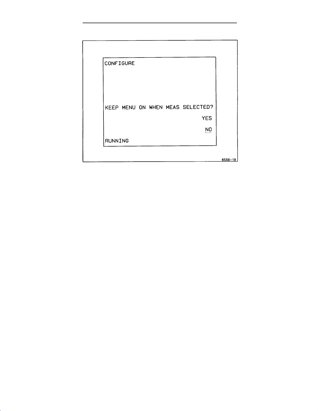
Operators Familiarization
Figure 3-9. Configure Menu.
KEEP READOUT ON IN SGL SEQ? Selecting NO will keep the readout off in
Single-Sequence Trigger Mode. This mode is useful for single-sequence
waveform photography. The readout is displayed briefly after the sequence
is completed to expose the film, then cleared to prevent overexposure.
Selecting YES keeps the readout on when in the Single-Sequence Trigger
Mode. This mode lets you view any of the measurements that continue to
be made during SGL SEQ trigger mode even if no waveform is being
displayed. The front panel control settings may also be made in SGL SEQ
without having to select a different Trigger Mode to see the readouts as the
controls are changed. The measurement readout is especially useful for the
Voltmeter measurements because the signal on the selected input channel
is continually monitored, (GATED Voltmeter measurements are not per-
mitted in SGL SEQ Trigger MODE.)
When the final question is answered, the SERVICE MENU display returns.
3-22 2246 1Y and 2246 Mod A Operators
Page 79

Operators Familiarization
Self Cal Measurements
This selection does a self-characterization of the vertical channels 1 and 2
and the horizontal timing. The SELF CAL MEASUREMENTS routine stores
calibration constants that set the accuracy of the internal measurement
system. Voltage or time measurements can be calibrated separately by
selecting the SELF CAL Item from the VOLTMETER or TIME Measurement
Menus.
NOTE
CALIBRATE MEASUREMENTS or SELF CAL can be performed
anytime after a 20-minute warmup to ensure the accuracy stated
in Section 6.
Internal Settings Menu
The INTERNAL SETTINGS MENU (see Figure 3-10) consists of MAKE
FACTORY SETTINGS, LOAD STORE/RECALL STORED SETUPS, and
ADJUST VERTICAL OUTPUT. All INTERNAL SETTINGS menu items,
except ADJUST VERTICAL OUTPUT,
return to the main SERVICE MENU, press the up-arrow key to underline
INTERNAL SETTINGS MENU and press the button again to display the
SERVICE MENU. To return to the oscilloscope mode, select QUIT from the
INTERNAL SETTINGS MENU or SERVICE MENU, or press the CLEAR
DISPLAY button.
are for use by the operator. To
MAKE FACTORY SETTINGS. Sets the front-panel controls and menu configurations as described In Appendix B.
LOAD STORE/RECALL SETUPS. This feature is not available on the 2246
1Y and 2246 Mod A oscilloscopes. However, if selected, the message
“THIS WILL DELETE PREVIOUSLY STORED SETUPS. CONTINUE?” ap-
pears. Pressing either YES or NO has no effect on instrument operation.
ADJUST VERTICAL OUTPUT. This menu item is to be used by a service
technician during calibration and troubleshooting. It is not an operational
function.
2246 1Y and 2246 Mod A Operators
3-23
Page 80

Operators Familiarization
3-24
Figure 3-10. Internal settings menu.
2246 1Y and 2246 Mod A Operators
Page 81

SECTION 4
OPERATOR
CHECKS AND
ADJUSTMENTS
2246 1Y and 2246 Mod A
Page 82

Page 83

Operator Checks and Adjustments
Introduction
The checks and adjustments in this section are for the operator and involve
using only controls and adjustments on the outside of the instrument. in-
ternal adjustments must be made by a qualified service person.
Before operating the instrument for the first time and before connecting the
power, refer to Section 1 “Preparation for Use” to prepare the instrument
for the initial start-up.
Verify that the POWER switch is OFF (out position). Plug the power cord
into a power-source outlet that supplies a voltage within the operating
range of the instrument’s power supply.
NOTE
If you notice an improper indication or instrument malfunction
during these procedures. refer the instrument to a qualified service person.
Initial Setup
The following procedure may be used to set up front-panel controls when
the instrument is first turned on or when a signal is not being applied to the
input connectors.
1. Press in the POWER switch button (ON) and let the instrument warm up
(20 minutes is recommended for maximum accuracy).
2. Set the Instrument front-panel controls to obtain a baseline trace:
Vertical Controls
VERTICAL MODE CH 1
POSITION Center the trace
VOLTS/DIV 1V
VOLTS/DIV VAR Calibrated detent
Channel 1 COUPLING GND
2246 1Y and 2246 Mod A Operators
4-1
Page 84

Operator Checks and Adjustments
Horizontal Controls
MODE
POSITION
X10 MAG
A SEC/DIV
SEC/DIV VAR
A
Center the trace
Off
0.1 ms
Calibrated detent
Trigger Controls
HOLDOFF
A/B SELECT
MODE
SOURCE
CPLG
Display
A INTEN
FOCUS Best trace definition
READOUT
SCALE ILLUM
MENU System Controls
MEASUREMENT MODES, All off (Press
TRACKING CURSORS CLEAR DISPLAY
and MENUS
MIN
A
AUTO LEVEL
VERT
DC
Desired brightness
Desired brightness
Desired brightness
three times to
ensure all off. )
Trace Rotation Adjustment
1.
Perform the “Initial Setup” procedure. Position the trace vertically to
align it with the center horizontal graticule line and check that the trace
is parallel with the gratlcule line.
NOTE
Normally, the trace will be parallel to the center horizontal
graticule line and the TRACE ROTATION adjustment will not be
needed.
4-2 2246 1Y and 2246 Mod A Operators
Page 85

Operator Checks and Adjustments
2. If necessary, adjust the TRACE ROTATION to make the baseline trace
parallel to the center horizontal graticule line. Use a small straight-blade
screwdriver or alignment tool.
Probe Low-Frequency Compensation
Misadjustment of probe compensation is a possible source of measurement
error. The attenuator probes are equipped with compensation adjustments.
To ensure the best measurement accuracy, always check probe compensation before making measurements.
1. Perform Initial Setup procedure.
2. Connect the two supplied 10X probes to the CH 1 and CH 2 BNC input
connectors.
3. Connect the probe tips to the PROBE ADJUST connector and the probe
ground leads to scope ground.
4. Set:
CH 1 & CH 2 COUPLING DC
A SEC/DIV
0.5 ms
5. Set the CH 1 VOLTS/DIV setting to 0.1 V (10 mV with probe disconnected) and vertically center the PROBE ADJUST square-wave signal.
6. Check the square-wave signal for overshoot and rolloff (see Figure
4-1). If necessary, use the special adjustment tool supplied in the probe
accessory package to adjust the low-frequency compensation for a
square front corner on the square wave displayed.
7. Press the CH 2 VERTICAL MODE button to turn CH 2 on in the display,
and press the CH 1 Mode button to remove the CH 1 trace from the
display.
8. Set the CH 2 VOLTS/DIV setting to 0.1 V (10 mV with probe disconnected) and vertically center the PROBE ADJUST square-wave signal.
9. Repeat Steps 5 and 6 for the second probe on the CH 2 BNC input
connector.
2246 1Y and 2246 Mod A Operators
4-3
Page 86

Operator Checks and Adjustments
Figure 4-1. Probe compensation.
NOTE
Refer to the instruction manual supplied with the probe for more
detailed information about the probes
procedure.
and the adjustment
Vertical
The PROBE ADJUST square-wave signal may be used to check the
Channel 1 and Channel 2 vertical deflection system in the following
procedure:
1. Perform Initial Setup procedure.
2. Connect the two 10X probes (supplied) to the CH 1 and CH 2 input
connectors.
3. Connect both probe hook tips to the PROBE ADJUST connector.
4-4
2246 1Y and 2246 Mod A Operators
Check
Page 87

Operator Checks and Adjustments
4
Set:
CH 1 & CH 2 COUPLING DC
VERTICAL MODE CH 1
Horizontal MODE
A SEC/DIV
5
Set CH 1 and CH 2 VOLTS/DIV switches to 0.1 V for the attached 10X
probes.
6
Set the bottom of the trace of the PROBE ADJUST square-wave signal
to a convenient horizontal graticule line with the Vertical POSITION
control.
7
Check for a five-division display of the PROBE ADJUST square-wave
signal.
8. Select CH 2 VERTICAL MODE and repeat steps 6 and 7.
9. Disconnect the probes from the Instrument.
A
0.5 ms
Timing Checks
The time measurement cursors may be used to check the horizontal
deflection system.
1. Preset instrument controls and obtain a baseline trace and set the
A SEC/DIV switch to 0.1 ms. Vertically center the baseline trace.
2. Press the TIME button to call up the Time Measurement Mode menu on
the crt and select
pressing the Menu Select button opposite menu label.
3. Align the reference cursor to the second vertical graticule line using the
[+
OR DELAY control (both cursors are positioned together).
4. Adjust the
5. Check that the cursors are eight divisions apart.
6. Press the CLEAR DISPLAY button to remove the cursors from the
display.
2246 1Y and 2246 Mod A Operators
k- SEC+I
x
control for a reading of 800.0
function for measuring time difference by
KS
4-5
Page 88

Page 89

SECTION 5
BASIC
APPLICATIONS
2246 1Y and 2246 Mod A
Page 90

Page 91

Basic Applications
Introduction
The TEKTRONIX 2246 1Y and 2246 Mod A Oscilloscopes provide an accurate and flexible measurement system. After becoming familiar with the
controls, indicators, menus, and capabilities of the instrument, you can
develop convenient methods for making special measurements for your own
applications. The measurements given in this section are examples of
typical applications that may assist in developing efficient techniques for
your specific measurements. A brief description of how the graticule
markings are used in making measurements Is given In Section 3 of this
manual.
When a procedure calls for “Initial Setup”, refer to Section 4, "Operator
Checks And Adjustments”. Certain signals such as video or aperiodic sig-
nals (non-repeating) and signals containing many unrelated frequency com-
ponents may require more trigger signal conditioning and/or holdoff to ob-
tain the best display.
CH 1/CH 2 Voltmeter Measurements
The CH 1/CH 2 Voltmeter measurements are continuous measurements of
the DC, +PEAK, -PEAK, or PK-PK values of an applied signal. The
measurement value is displayed in the crt readout. Measurement tracking
and/or ground tracking cursors may be displayed to give the user instant
feedback about where on the applied signal the measurement is being made
and the location of ground level.
GATED modes of +PEAK, -PEAK, and PK-PK measurements may be used
to define the area of the measurement on the displayed waveform. The
position and width of the gated region is displayed as an intensified zone on
the A trace of the waveform display. Position of the gated region on the
1+
waveform is controlled by the
region is controlled by the
Some features of the CH 1/CH 2 Voltmeter function are:
a. Measures CH 1 or CH 2 while viewing either channel. (Select the
measurement source channel using the SET MEAS’MT CHANNEL
menu.)
b. Measures signal levels (DC values and peaks) in SGL SEQ (single-
sequence) Trigger MODE continuously. (Use CONFIGURE function
in the Service Menu to get menus and readouts to remain on
between single sequence triggers.)
2246 1Y and 2246 Mod A Operators
OR DELAY control, and width of the gated
~
control.
5-1
Page 92

Basic Applications
c. Finds peaks of signal applied, not only just the displayed portions of
the waveform.
d. Defines a portion of the waveform (GATED measurements are es-
pecially useful for making measurements on a multi-level signal) on
which to make the selected measurement. (Use page 2 of the
VOLTMETER menu to select a GATE D-measurement mode.)
NOTE
Very narrow-gated measurements at 20 ns per div sweep speed
are impractical/ due to imprecise definition of the inten sified zone
at that sweep speed.
Peak Voltage Measurement
To make a +peak voltage measurement use the following procedure:
1. Apply the signal to be measured to CH 1 input connector.
2. Set:
CH1 VOLTS/DIV so that entire signal is on screen
and POSITION
Vertical MODE CH 1
Horizontal SEC/DIV so that at least 1 cycle is displayed
Horizontal MODE A
3. Press the VOLTMETER CH1/CH2 button to call up the selection menu
and select the +PEAK choice. Any of the page one choices may be
selected as required for the waveform measurement wanted.
Depending on the way the CONFIGURE choices of the SERVICE menu
have been made, the menu will either go off when the measurement
selection is made or it will stay on. If the menu remains on, press the
CLEAR DISPLAY button once to remove it from the display. See the
SERVICE Menu discussion in Section 3 for further details.
5-2 2246 1Y and 2246 Mod A Operators
Page 93

Basic Applications
NOTE
The TRACK MEASMT cursor may be displayed with the
waveform. Pressing CLEAR DISPLAY in the initial setup removes
the measurement tracking cursor from the display (and also cancels the measurement) but does not disable the feature once it
has been enabled; the next time a CH 1/CH 2 Voltmeter
measurement mode is called for, the measurement tracking
cursor is again displayed.
4. Press the CURSORS button and display page 2 of the menu by selecting
the (TO AUTO TRACKING MENU) choice. Of the three features avail-
~.
able in page 2, select both TRACK MEASMT and TRACK
labels are UNDERLINED
cursor is especially useful for providing feedback to the user about dc
offset of the signal from ground level.
In this menu, the select buttons toggle the choices on and off
with each press, and all three choices may be selected (but not
all displayed together because only two cursors are allowed).
Also, pressing CLEAR DISPLAY (as many as three times may be
necessary) does turn off the TRACK TRIG LVL and TRACK
choices.
when the function is enabled. The TRACK
NOTE
Menu
A
~
5. Press either MENU OFF (in the menu selection list) or CLEAR DISPLAY
(once) to remove the AUTO TRACKING menu from the display.
NOTE
If VOLTMETER PK-PK measurement is selected, two TRACK
&
MEASMT cursors are required; therefore, the TRACK
will not be displayed.
6. See Figure 5-1. The test signal used for the example has a dc offset
~
(as shown by the position of the TRACK
(peak ac + dc) as indicated by the voltage readout.
2246 1Y and 2246 Mod A Operators
cursor) and +PEAK value
cursor
5-3
Page 94

Basic Applications
Gated Voltage Measurement
If you need to track the +PEAK, -PEAK, or PK-PK voltage of a selected
portion of a waveform, that portion can be defined using the GATED
MEASUREMENTS available in page 2 of the VOLTMETER menu. The
general steps given in the previous Peak Voltage Measurement procedure
are used for this function also. Set up all the controls and apply the signal to
be measured in the same way; but, after pressing the VOLTMETER
CH1/CH2 button, select the (TO GATED MEASMT MENU) choice. After
that, follow these additional steps to make the gated measurement.
Figure 5-1. +PEAK voltage measurement and tracking cursors.
5-4
2246 1Y and 2246 Mod A Operators
Page 95

Basic Applications
1. Select GATED +PEAK measurement mode. The menu will be removed
(if configured to do so), and any enabled tracking cursors will be
displayed. If none are enabled in page 2 of the CURSORS menu, none
will be displayed.
NOTE
Only two of the possible three available selections may be dis-
played (on a priority basis). TRACK MEASMT has the highest
rb
priority, followed by TRACK TRIG LVL and TRACK
order. Also the TRACK TRIG LVL cursors may only be displayed
on the Trigger SOURCE signal. The TRACK MEASMT cursor
may be directed to either CH 1 or CH 2 input signal without
regard to the trigger signal SOURCE.
2. Adjust the B INTEN and A INTEN controls to provide a good viewing
contrast of the intensified zone that appears on the A Sweep trace.
NOTE
in that
If the zone does not appear, it may be positioned out of the
viewing area (but not past the end of the A Sweep trace). Turn
k-
OR DELAY control counterclockwise to move the gate zone
the
closer to the beginning of sweep.
1+
3. Use the
of interest on the waveform to be tracked. (See Figure 5-2.)
4. The width of the gated zone Is controlled by the
width to define the gated measurement zone.
5. The voltage value that appears In the readout Is the +PEAK voltage that
occurs within the zone.
2246 1Y and 2246 Mod A Operators
OR DELAY control to position the intensified zone to the area
~
control. Adjust the
5-5
Page 96

Basic Applications
Figure 5-2. Gated voltage measurement.
Voltage Measurement Cursors
Voltage cursors can be used to measure signals displayed on CH 1 or CH 2.
Voltage measurements using cursors may be done on the CH 3, the CH 4,
or the ADD waveform by setting the VOLTS/DIV switch setting of the
selected measurement channel to the same scale factor as the signal to be
measured. However, the measurement accuracy on the CH 3 or CH 4 input
signals will be less accurate than on the CH 1 or CH 2 input signals. Volts
cursors are also available for making measurements in both the A Horizontal MODE and the X-Y Horizontal MODE.
Voltage Difference
Use the following procedure steps as a guideline in making voltage difference measurements using the positionable cursors.
1. Apply the signal to the input connector(s).
5-6
2246 1Y and 2246 Mod A Operators
Page 97

Basic Applications
2. Set:
Vertical MODE As desired
CH 1 and/or CH 2 so that entire signal is on screen
VOLTS/DIV
and POSITION
Horizontal SEC/DIV
Horizontal MODE A or X-Y
3. Press the CURSOR VOLTS button to display the measurement selection
menu and select the
initialized to the peak-to-peak levels of the lowest numbered displayed
channel of either CH 1 or CH 2 (see Figure 5-3).
so that at least 1 cycle is displayed
k-
VOLTS +1 cursors. The voltage cursors are
Figure 5-3. Voltage difference measurement using cursors.
2246 1Y and 2246 Mod A Operators
5-7
Page 98

Basic Applications
NOTE
Voltage cursors are initialized to leve/s seen by the peak detector
circuitry. Noise and other signals riding on the signal to be
measured will cause a slight displacement of the cursors from the
displayed waveform peaks, and above 50 MHz the bandwidth
rolloff of the trigger circuit will affect the initial cursor positions
on the waveform.
4. For a peak-to-peak voltage measurement, slightly reposition the cursors as necessary to precisely align them with the peak amplitudes of
1+
the waveform, and the work is done. The
both cursors together (keeping the original spacing], and the
positions the independent cursor. Then, simply read the measurement
value displayed in the top line of the readout.
5. To make voltage difference measurements between any other locations
on the waveform, simply move the
and then position the independent
waveform and read the voltage difference.
OR DELAY control positions
~
control
I+
cursor to the new point of interest
~
cursor to the second point on the
Ground-Referenced Voltage
Voltage measurements using ground as a reference are made using the
~
VOLTS ~ cursors. The ground tracking cursor is fixed at the ground
level of the applied signal and the independent cursor above or below
ground as necessary to measure the voltage at the cursor position. Use the
following procedure to set up ground-referenced voltage measurements.
1. Apply the signal to the input connector(s).
2. Set:
Vertical MODE
CH 1 and/or CH 2
VOLTS/DIV
and POSITION
CH 1/CH 2 COUPLING
Horizontal SEC/DIV
Horizontal MODE
5-8
As desired
so that entire signal I
DC
so that at least 1 cycle Is displayed
A
2246 1Y and 2246 Mod A Operators
S on screen
Page 99

Basic Applications
3.4.Press the CURSORS button to display the measurement selection menu
~
and select the
ized to the +PEAK of the Input waveform.
Position the independent cursor using the
ment point on the waveform and read out the value of the cursor
position (shown in Figure 5-4). (The
effect.)
The test signal used for illustration purposes in Figure 5-4 is a
video test signal. For triggering on a video waveform, select TV
LINE Trigger COUPLING and negative
other signal types, no change of COUPLING or SLOPE is
required.
VOLTS +[ cursors. The independent cursor is initial-
~
control to the measure-
~
OR DELAY control has no
NOTE
(1)
Trigger SLOPE; for
Figure 5-4. Voltage measurement.
2246 1Y and 2246 Mod A Operators
5-9
Page 100

Basic Applications
Time Measurement Cursors
Time measurement cursors may be used on any of the input waveforms
only in the A Horizontal MODE. (Time measurements are also available in
ALT and B Horizontal modes; see "Time Delay Measurement” in this
section.) The units of the time cursors may be selected to provide some
automatic calculations for the user. The units of the
VS,
time (s, ms,
(Hz, KHz, and MHz), and the
scaled to a 360 degree reference set by the user.
and ns), the K- 1/SEC +1 cursors have units of frequency
ie
PHASE +1 cursor units are in degrees and
Time Difference
Use the following procedure steps as a guideline in making time difference
measurements using the
1+
cursors, the
~
control positions the independent cursor,
1. Apply the signal to the input connector(s).
2. Set:
OR DELAY control positions both cursors together, and the
k- SEC -N cursors. As with the It VOLTS -4
k-
SEC al cursors are
Vertical MODE
CH 1 and/or CH 2
VOLTS/DIV
and POSITION
Horizontal MODE A
3. Select
4. Press TIME button and select
5. Use the
a SEC/DIV setting that provides the fewest number of cycles of
the applied waveform necessary to display the measurement points of
interest. This is to improve the accuracy of cursor placement for the
measurement.
The independent cursor cannot be positioned in front of the
reference cursor.
[+
OR DELAY control to position the reference cursor to the
point on the waveform to be measured from. Use the
position the independent cursor to the second point of interest. Then,
read the time difference value in the top line of the crt readout.
5-10
As desired
so that entire signal is on screen
l+
SEC +1 from menu.
NOTE
~
2246 1Y and 2246 Mod A Operators
control to
 Loading...