

Page 1

Tektronix-
2213A
OSCILLOSCOPE
OPERATORS
INSTRUCTION MANUAL
Page 2

2213A Operators
TABLE OF
Page
LIST OF ILLUSTRATIONS
......................................
M
LIST OF TABLES ..................................................... ii
OPERATORS SAFETY SUMMARY
........................
Mi
Section 1 GENERAL INFORMATION
INTRODUCTION
................................
1-1
SPECIFICATION
..................................
1-1
CALIBRATION
......................................
1-9
REPACKAGING FOR SHIPMENT .... 1-9
Section 2 PREPARATION FOR USE
FIRST-TIME START UP
....................
2-1
SAFETY
..........................................
2-1
LINE VOLTAGE
..............................
2-1
POWER CORD
..............................
2-1
LINE FUSE
....................................
2-1
INSTRUMENT COOLING
..............
2-2
CONTROLS, CONNECTORS, AND
INDICATORS
......................................
2-3
DISPLAY, POWER, AND PROBE
ADJUST
..........................................
2-3
VERTICAL
......................................
2-4
HORIZONTAL
................................
2-5
TRIGGER
........................................
2-6
REAR PANEL
................................
2-7
Section 3 OPERATORS FAMILIARIZATION
GENERAL OPERATING
INFORMATION
....................................
3-1
GRATICULE
....................................
3-1
GROUNDING
..................................
3-1
SIGNAL CONNECTIONS
..............
3-1
CONTENTS
Section 3 OPERATORS FAMILIARIZATION (cont)
INPUT COUPLING CAPACITOR
PRECHARGING
............................
3-1
OPERATOR’S ADJUSTMENTS
........
3-3
INTRODUCTION
............................
3-3
BASELINE TRACE
........................
3-3
TRACE ROTATION
........................
3-3
PROBE COMPENSATION
............
3-3
Section 4 OPERATING PROCEDURES
BASIC APPLICATIONS
......................
4-1
INTRODUCTION
............................
4-1
INDEX TO BASIC APPLICATION
PROCEDURES
..............................
4-1
VOLTAGE MEASUREMENTS
........
4-1
TIME MEASUREMENTS
..............
4-4
TELEVISION DISPLAYS
................
4-8
DELAYED-SWEEP
MAGNIFICATION
............................
4-9
Section 5 OPTIONS AND ACCESSORIES
INTRODUCTION
............................
5-1
OPTIONS
........................................
5-1
INTERNATIONAL POWER CORDS 5-1
STANDARD ACCESSORIES
........
5-1
OPTIONAL ACCESSORIES
..........
5-1
FRONT PANEL ILLUSTRATION
CHANGE INFORMATION
REV DEC 1983
I
Page 3

2213A Operators
LIST OF ILLUSTRATIONS
Figure Page
The 2213A Oscilloscope ....................................................................................................................................... iv
1-1 Maximum input voltage vs frequency derating curve for CH 1 OR X, CH 2 OR Y, and EXT INPUT connectors .. 1-7
1- 2 Physical dimensions of the 2213A Oscilloscope.................................................................................................... 1-8
2- 1 Optional power cords............................................................................................................................................ 2-1
2-2 Fuse holder and power cord connector................................................................................................................ 2-2
2-3 Power and display controls and indicators and PROBE ADJUST output
...........................................................
2-3
2-4 Vertical controls and connectors .......................................................................................................................... 2-4
2-5 Horizontal controls................................................................................................................................................ 2-5
2-6 Trigger controls, connector, and indicator............................................................................................................ 2-6
2- 7 Rear panel connector............................................................................................................................................ 2-7
3- 1 Graticule measurement markings.......................................................................................................................... 3-1
3- 2 Probe compensation ............................................................................................................................................ 3-4
4- 1 Peak-to-peak waveform voltage .......................................................................................................................... 4-2
4-2 Instantaneous voltage measurement.................................................................................................................... 4-3
4-3 Common-mode rejection ...................................................................................................................................... 4-4
4-4 Voltage ratios........................................................................................................................................................ 4-4
4-5 Time Duration........................................................................................................................................................ 4-5
4-6 Rise Tim e.............................................................................................................................................................. 4'6
4-7 Time difference between pulses on time related signals....................................................................................... 4-6
4-8 Phase difference.................................................................................................................................................... 4~7
4-9 High-resolution phase difference .......................................................................................................................... 4-8
4-10 Delayed-sweep magnification................................................................................................................................ 4-9
LIST OF TABLES
Table Page
1-1 Electrical Characteristics........................................................................................................................................ 1-2
1-2 Environmental Characteristics...............................................................................................................................
1- 3 Physical Characteristics........................................................................................................................................ 1"7
2- 1 VERT MODE Trigger Source................................................................................................................................ 2-7
Page 4

1
2213A Operators
#
1
“J
J
1
1 J
h
i
OPERATORS SAFETY SUMMARY
The general safety information in this part o f the summary is fo r both operating and servicing personnel. Specific warnings
and cautions will be found throughout the manual where they apply and do not appear in this summary.
Terms in This Manual
CAUTION statements identify conditions or practices that
could result in damage to the equipment or other property.
WARNING statements identify conditions or practices
that could result in personal injury or loss of life.
Terms as Marked on Equipment
CAUTION indicates a personal injury hazard not immedi
ately accessible as one reads the markings, or a hazard to
property, including the equipment itself.
DANGER indicates a personal injury hazard immediately
accessible as one reads the marking.
Symbols in This Manual
This symbol indicates where applicable
A
cautionary or other information is to be found.
For maximum input voltage see Table 1-1.
Symbols As Marked on Equipment
A
DANGER — High voltage.
Protective ground (earth) terminal.
ATTENTION — Refer to manual.
LvJ
Power Source
This product is intended to operate from a power source
that does not apply more than 250 volts rms between the
supply conductors or between either supply conductor and
ground. A protective ground connection by way of the
grounding conductor in the power cord is essential for safe
operation.
Grounding the Product
This product is grounded through the grounding conductor
of the power cord. To avoid electrical shock, plug the power
cord into a properly wired receptacle before connecting to
the product input or output terminals. A protective ground
connection by way of the grounding conductor in the power
cord is essential for safe operation.
Danger Arising From Loss of Ground
Upon loss of the protective-ground connection, all accessi
ble conductive parts (including knobs and controls that may
appear to be insulating) can render an electric shock.
Use the Proper Power Cord
Use only the power cord and connector specified for your
product.
Use only a power cord that is in good condition.
For detailed information on power cords and connectors
see Figure 2-1.
Use the Proper Fuse
To avoid fire hazard, use only a fuse of the correct type,
voltage rating and current rating as specified in the parts list
for your product.
Do Not Operate in Explosive Atmospheres
To avoid explosion, do not operate this product in an explo
sive atmosphere unless it has been specifically certified for
such operation.
Do Not Remove Covers or Panels
To avoid personal injury, do not remove the product covers
or panels. Do not operate the product without the covers
and panels properly installed.
m
Page 5

2213A Operators
The 2213A Oscilloscope.
IV
Page 6

Section 1—2213A Operators
1
1
1
" 1
1
GENERAL INFORMATION
INTRODUCTION
The TEKTRONIX 2213A Oscilloscope is a rugged, light
weight, dual-channel 60 MHz instrument that features a
bright, sharply defined trace on an 80- by 100 mm cathode-
ray tube (crt). Its vertical system supplies calibrated deflec
tion factors from 2 mV per division to 5 V per division.
Trigger circuits enable stable triggering over the full band
width of the vertical system. The horizontal system provides
calibrated sweep speeds from 0.5 s per division to 50 ns per
division, along with a delayed-sweep feature. A X I0 magni
fier circuit extends the maximum sweep speed to 5 ns per
division when the SEC/DIV switch is set to 0.05 fis per
division.
The instrument is shipped with the following standard
accessories:
1 Operators manual 2 Probe packages
1 Power cord
For part numbers and information about instrument ac
cessories, refer to the “Options and Accessories” section of
this manual.
The service manual and all other optional accessories are
orderable from Tektronix, Inc. A local Tektronix Field Office,
representative, or the Tektronix product catalog can provide
ordering and product information.
SPECIFICATION
The following electrical characteristics (Table 1-1) are
valid for the 2213A when it has been adjusted at an ambient
temperature between +20°C and +30°C, has had a warm
up period of at least 20 minutes, and is operating at an
ambient temperature between 0°C and +50°C (unless oth
erwise noted).
Items listed in the “Performance Requirements” column
are verifiable qualitative or quantitative limits, while items
listed in the “Supplemental Information” column are either
explanatory notes, calibration setup descriptions, perfor
mance characteristics for which no absolute limits are speci
fied, or characteristics that are impractical to check.
Environmental characteristics are given in Table 1-2. The
2213A meets the requirements of MIL-T-28800C, para
graphs 4.5.5.1.3, 4.5.5.1.4, and 4.5.5.1.2.2 for type III,
Class 5 equipment, except where otherwise noted.
Physical characteristics of the instrument are listed in
Table 1-3.
REV DEC
1983
1-1
Page 7

General Information— 2213A Operators
Table 1-1
Electrical Characteristics
Characteristics Performance Requirements
Supplemental Information
VERTICAL DEFLECTION SYSTEM
Deflection Factor
Range
2 mV per division to 5 V per division
in a 1-2-5 sequence.
5 mV per division to 5 V per division
gain is adjusted with VOLTS/DIV switch
set to 10 mV per division.
2 mV per division gain is adjusted
with VOLTS/DIV switch set to 2 mV
per division.
Accuracy
±3%
Range of VOLTS/DIV Variable Control Continuously variable between
settings. Increases deflection factor
by at least 2.5 to 1.
Step Response Rise Time
Rise time is calculated from the formula:
Rise Time
0.35
0°C to + 35°C
Bandwidth (—3 dB)
5 mV per Division to 5 V per
Division
5.8 ns or less.
0°C to 50°C
2 mV per Division to 5 V per
Division
7.0 ns or less.
Bandwidth (—3 dB)
0°C to +35°C
2 mV per Division
Dc to at least 50 MHz.
Measured with a vertically centered
6-division reference signal from a 50 Q
source driving a 50 (1 coaxial cable
that is terminated in 50 fl, both at
the input connector and at the probe
input, with the VOLTS/DIV Variable
control in the CAL detent.
5 mV per Division to 5 V per
Division
Dc to at least 60 MHz.
0°C to +50°C
2 mV per Division to 5 V per
Division
Dc to at least 50 MHz.
AC Coupled Lower Limit
10 Hz or less at - 3 dB.
Bandwidth Limiter
Upper limits ( - 3 dB) bandpass at
10 MHz ±15%.
Chop Mode Switching Rate
500 kHz ±30%.
Input Characteristics
Resistance
1 Mfl ±2%.
Capacitance
20 pF ±2 pF.
Maximum Safe Input Voltage 2 ^ ^
DC Coupled
400 V (dc + peak ac) or 800 V ac p-p
to 10 kHz or less.
See Figure 1 -1 for derating curve.
AC Coupled
400 V (dc + peak ac) or 800 V-ac p-p
to 10 kHz or less.
1-2
REV MAR 1984
K
Page 8

General Information—2213A Operators
1
1
1
1
1
1
1
Table 1-1 (cont)
Characteristics
Performance Requirements
Supplemental Information
VERTICAL DEFLECTION SYSTEM (cont)
Common-Mode Rejection Ratio
(CMRR)
At least 20 to 1 at 25 MHz.
Checked at 10 mV per division for
common-mode signals of 6 divisions or
less with VOLTS/DIV Variable control
adjusted for best CMRR at 50 kHz.
Trace Shift with Attenuator Rotation 0.75 division or less.
VOLTS/DIV Variable control in CAL
detent.
Trace Shift as VOLTS/DIV
Variable Control is Rotated
1.0 division or less.
Trace Shift with Invert 1.5 division or less.
Channel Isolation Greater than 100 to 1 at 25 MHz.
TRIGGER SYSTEM
TRIGGER Sensitivity
P-P AUTO/TV LINE and NORM
Modes
Internal
External trigger signal from a 50 Q
source driving a 50 Q coaxial cable
terminated in 50 Q at the input connector.
5 MHz 60 MHz
0.3 div
1.0 div
External
40 mV
150 mV
Lowest Useable Frequency in P-P
AUTO Mode
20 Hz with 1.0 division internal
or 100 mV external.
TV FIELD Mode
1.0 division of composite sync.
EXT INPUT
Maximum Input Voltage
400 V (dc + peak ac) or 800 V ac p-p
at 10 kHz or less.
See Figure 1 -1 for derating curve.
Input Resistance
1 Mfl ±2%.
Input Capacitance
20 pF ±2.5 pF.
AC Coupled
10 Hz or less at lower - 3 dB point.
LEVEL Control Range (NORM)
INT
Can be set to any point of the trace
that can be displayed.
EXT, DC
At least ± 1.6 V, 3.2 V p-p.
EXT, DC -=- 10
At least ± 16 V, 32 V p-p.
VAR HOLDOFF Control
Increases Sweep holdoff time by at
least a factor of 10.
u
REV DEC 1983 1-3
Page 9

General Information—2213A Operators
Table 1-1 (cont)
Characteristics
Performance Requirements Supplemental Information
HORIZONTAL DEFLECTION SYSTEM
Sweep Rate 0.5 s per division to 0.05 ns per
division in a 1-2-5 sequence. XI0
magnifier extends maximum sweep
speed to 5 ns per division.
Accuracy Unmagnified Magnified Sweep accuracy applies over the
center 8 divisions. Exclude the first
25 ns of the sweep for magnified
sweep speeds and anything beyond
the 100th magnified division.
+ 15°C to +35°C
±3%
±4%
0°C to +50°C
±4%
±5%
POSITION Control Range Start of sweep to 10th division in XI or
100th divisions in XI0 will position past
the center vertical graticule line.
Sweep Linearity
±7%.
Linearity measured over any 2 of the
center 8 divisions. With magnifier in XI0,
exclude the first 25 ns and anything past
the 100th division.
Variable Control Range
Continuously variable between
calibrated settings. Extends the sweep
speed by at least a factor of 2.5.
Delay Time
Delay Positions
Minimum less than 1.0 ns, 20 vs, and
0.4 ms.
MULTIPLIER
Increases delay time by at least a
factor of 50.
Jitter
One part or less in 10,000 (0.01%) of
the maximum available delay time.
X-Y OPERATION (XI MAGNIFICATION)
Deflection Factory
Same as Vertical Deflection System
(with VOLTS/DIV Variable controls in
CAL detent).
Accuracy
X-Axis
±4%.
Measured with a dc-coupled, 5-division
reference signal.
Y-Axis
Same as Vertical Deflection System.
Bandwidth (-3dB )
X-Axis
Dc to at least 2 MHz.
Measured with a 5-division
reference signal.
Y-Axis
Same as Vertical Deflection System.
Phase Difference Between X- and
Y-Axis Amplifiers
±3° from dc to 100 kHz.
With dc-coupled inputs.
1-4
REV DEC 1983
Page 10

General Information—2213A Operators
Table 1-1 (cont)
Characteristics Performance Requirements
Supplemental Information
PROBE ADJUST
Output Voltage of PROBE ADJUST
Jack
0.5 V ±5%.
Repetition Rate
1 kHz ±20%.
Z-AXIS INPUT
Sensitivity
5 V causes noticeable modulation.
Positive-going input decreases
intensity.
Useable frequency range is
dcto 10 MHz.
Maximum Safe Input Voltage
30 V (dc + peak ac) or 30 VC p-p ac at
1 kHz or less.
Input Resistance
lO kfl ±10%.
POWER SOURCE
Line Voltage Ranges
90 V to 250 V.
Line Frequency
48 Hz to 440 Hz.
Maximum Power Consumption 40 W (70 VA).
Line Fuse
1.0 A, 250 V, slow-blow.
CATHODE-RAY TUBE
Display Area
80 by 100 mm.
Standard Phosphor
P31.
Nominal Accelerating Voltage
14 kV.
REV DEC 1983
1-5
Page 11

General Information—2213A Operators
Table 1-2
Environmental Characteristics
___________________________________________________________________
£
Characteristics
Description
Temperature
NOTE
The instrument meets the requirements of MIL-T-28800C, paragraphs 4.5.5.1.3,
4.5.5.1.4, and 4.5.5.1.2.2 for Type III, Class 5 equipment, except where other
wise noted.
Operating
0°C to +50°C (+32°F to +122°F).
Nonoperating
-55°C to +75°C (-67°F to +167°F). Tested to MIL-T-28800C paragraphs
4.5.5.1.3 and 4.5.5.1.4, except in 4.5.5.1.3 steps 4 and 5 (0°C operating test) are
performed ahead of step 2 (—55 °C nonoperating test). Equipment shall remain
off upon return to room ambient during step 6. Excessive condensation shall be
removed before operating during step 7.
Altitude
Operating
To 4,500 m (15,000 ft). Maximum operating temperature decreased 1 °C per
1,000 ft above 5,000 ft.
Nonoperating To 15,000 m (50,000 ft).
Humidity (Operating and Nonoperating) 5 cycles (120 hours) referenced to MIL-T-28800C paragraph 4.5.5.1.2.2 for Type
III, Class 5 instruments. Operating and non-operating at 95% +0% to -5 % a
relative humidity. Operating at +50°C and +30°C. Non-operating at +30°C to
+60°C.
Vibration (Operating)
15 minutes along each of 3 major axes at a total displacementof 0.015 inch p-p
(2.4 g’s at 55 Hz) with frequency varied from 10 Hz to 55 Hz to 10 Hz in 1-minute
sweeps. Hold for 10 minutes at 55 Hz in each of the 3 major axes. All major
resonances must be above 55 Hz.
Shock (Operating and Nonoperating)
30 g’s, half-sine, 11-ms duration, 3 shocks per axis each direction, for a total of
18 shocks.
EMI
Meets radiated and conducted emission requirements per VDE 0871 Class B.
1-6
REV DEC 1983
Page 12

Table 1-3
Physical Characteristics
General Information—2213A Operators
Characteristics
Description
Weight With Power Cord
With Cover, Probes, and Pouch
6.0 kg (13.1 lb).
Without Cover, Probes, and Pouch
5.0 kg (10.9 lb).
Domestic Shipping Weight
7.0 kg (15.4 lb).
Height
With Feet and Handles
137 mm (5.4 in).
Width
With Handle
360 mm (14.2 in).
Without Handle
327 mm (12.9 in).
Depth
With Front Cover
445 mm (17.5 in).
Without Front Cover
440 mm (17.3 in).
With Handle Extended
511 mm (20.1 in).
VOL T S
10 KHz 50 KHz 100 KHz 500 KHz 1 MHz 100 MHz
FREQUENCY
C4207-28
Figure 1-1. Maximum input voltage vs. frequency derating curve for CH 1 OR X, CH 2 OR Y, and EXT INPUT connectors.
REV DEC 1983
1-7
Page 13

General Information—2213A Operators
1-8
ADD DEC 1983
Figure 1-2. Physical dimensions of the 2213A Oscilloscope.
Page 14

General Information—2213A Operators
CALIBRATION
Instrument performance should be checked after every
2000 hours of operation or once each year if used infre
quently. A more frequent interval may be necessary if your
instrument is subjected to harsh environments or severe
usage.
REPACKAGING FOR SHIPMENT
If the instrument is to be shipped to a Tektronix Service
Center for service or repair, attach a tag showing; owner
(with address) and the name of an individual at your firm
that can be contacted. Include complete instrument serial
number and a description of the service required.
Save and reuse the package in which your instrument
was shipped. If the original packaging is unfit for use or not
available, repackage the instrument as follows:
Surround the instrument with polyethylene sheeting to
protect its finish. Obtain a carton of corrugated cardboard
having a carton test strength of 275 pounds and having
inside dimensions of no less than six inches more than the
instrument dimensions. Cushion the instrument by tightly
packing three inches of dunnage or urethane foam between
carton and instrument, on all sides. Seal carton with ship
ping tape or industrial stapler.
ADD DEC 1983
1-9
Page 15

Section 2—2213A Operators
PREPARATION FOR USE
FIRST-TIME START UP
SAFETY
Refer to the “Operators Safety Summary” at the front of
this manual for power source, grounding, and other safety
considerations pertaining to the use of the 2213A. Before
connecting the instrument to a power source, carefully read
the following about line voltages, power cords, and fuses.
LINE VOLTAGE
The instrument is capable of continuous operation using
input voltages that range from 90 V to 250 V nominal at
frequencies from 48 Hz to 440 Hz.
POWER CORD
A detachable three-wire power cord with a three-contact
plug is provided with each instrument to permit connection
to both the power source and protective ground. The plug
protective-ground contact connects (through the protective-
ground conductoi)to the accessible metal parts of the instru
ment. For electrical-shock protection, insert this plug only
into a power outlet that has a securely grounded protective-
ground contact.
This instrument is shipped with the required power cord
as ordered by the customer. Available power-cord informa
tion is illustrated in Figure 2-1, and part numbers are listed in
Section 5 of this manual Tkxitact your Tektronix represen
tative or local Tektronix Field Office for additional power-
cord information.
LINE FUSE
The instrument fuse holder is located on the rear panel
(see Figure 2-2) and contains the line fuse. The following
procedure can be used to verify that the proper fuse is in
stalled or to install a replacement fuse.
1. Unplug the power cord from the power-input source
(if applicable).
Plug
Configuration
Usage
Line
Voltage
Reference
Standards
North
Am erican
120V /
15 A
12 0V
ANSI C73 .11
NEM A 5-15 -P
IEC 83
Universal
Euro
240V /
10-16 A
24 0V
CEE |7).11,1V,VII
IEC 83
UK
240V /
13 A
24 0V
BS 1363
IEC 83
Au stralian
240V /
10 A
24 0V
AS C1 12
North
Am erican
240V /
15 A
24 0V
AN SI C 73.20
NEM A 6 -15-P
IEC 83
Sw itzerland
220V /
10A
22 0V SEV
Abbreviations:
ANS I - American N ational Standards Institu te
AS — Standards Association o f Australia
BS — British Standards Institutio n
CEE — Internationa l Com mission on Rules for the
Ap proval of Ele ctric al Equipment
IEC — Internatio nal Electrotechn ical Com mission
NEM A — Na tional Electrical M anu fa cturer's Association
SEV — Schw eizevischer E le ktrotechischer Verein C4732-02
Figure 2-1. Optional power cords.
2. Press in and slightly rotate the fuse-holder cap coun
terclockwise to release it.
3. Pull the cap (with the attached fuse inside) out of the
fuse holder.
4. Verify proper fuse value (1.0 A, 250 V, slow blow).
5. Reinstall the fuse (or replacement fuse) and the fuse-
holder cap.
REV APR 1985
2-1
Page 16

Preparation For Use—2213A Operators
LINE
FUSE
A
CAUTION
fo r c o n t in u ed fi re pr ote ct io n
REPLACE ONLY W ITH SPECIFIED
TYPE ANO RATEO FUSE DISCONNECT
POWER INPUT BEFORE REPLACING FUSE
LINE VOLTAGE RANGE FUSE 250V
90-25 0VAC IA SLOW
CAUTION
TO AVOID ELECTRIC
SHOCK. THE POWER
CORO PROTECTIVE
GROUNDING CONDUCTOR "
MUST BE CONNECTED
TO GROUND
POWER
CORD
C4207-03
INSTRUMENT COOLING
Always maintain adequate instrument cooling. The venti
lation holes on both sides of the instrument cabinet and on
the rear panel must remain free of obstruction.
Figure 2-2. Fuse holder and power cord connector.
Page 17

Preparation For Use—2213A Operators
CONTROLS, CONNECTORS, AND INDICATORS
The following descriptions are intended to familiarize the
operator with the location, operation, and function of the
instrument’s controls, connectors, and indicators.
DISPLAY, POWER, AND PROBE ADJUST
Refer to Figure 2-3 for location of items 1 through 8.
M ) Internal Graticule—Eliminates parallax viewing error
between the trace and graticule lines. Rise-time ampli
tude and measurement points are indicated at the left
edge of the graticule.
© POWER Switch—Turns instrument power on and off.
Press in for ON; press again for OFF.
( 3) Power Indicator—An LED that illuminates when the
instrument is operating.
( T ) FOCUS Control—Adjusts for optimum display
definition.
H j j PROBE ADJUST Connector—Provides an approxi-
mately 0.5 V, negative-going, square-wave voltage (at
approximately 1 kHz) that permits an operator to
compensate voltage probes and to check operation of
the oscilloscope vertical system. It is not intended for
verifying the accuracy of the vertical gain or time-base
circuitry.
BEAM FIND Switch—When held in, compresses the
display to within the graticule area and provides a visi
ble viewing intensity to aid in locating off-screen
displays.
C l j TRACE ROTATION Control—Screwdriver adjust-
ment used to align the crt trace with the horizontal
graticule lines.
f 8J INTENSITY Control—Determines the brightness of
y the sweep trace.
2-3
Figure 2-3. Power and display controls and indicators and PROBE ADJUST output.
Page 18

Preparation For Use—2213A Operators
VERTICAL
Refer to Figure 2-4 for location of items 9 through 16.
(jT ) CH 1 VOLTS/DIV and CH 2 VOLTS/DIV Switches—
Used to select the vertical deflection factor in a 1-2-5
sequence. To obtain a calibrated deflection factor, the
VOLTS/DIV variable control must be in the calibrated
(CAL) detent (fully clockwise).
IX—Indicates the deflection factor selected when
using either a 1X probe or a coaxial cable.
10X PROBE—Indicates the deflection factor se
lected when using a 10X probe.
® VOLTS/DIV Variable Controls—When rotated coun
terclockwise out of their calibrated detent positions,
these controls provide continuously variable,
uncalibrated deflection factors between the calibrated
settings of the VOLTS/DIV switches.
POSITION Controls—Used to vertically position the
display on the crt. When the SEC/DIV switch is set to
X-Y, the Channel 2 POSITION control moves the dis
play vertically (Y-axis), and the Horizontal POSITION
control moves the display horizontally (X-axis).
Figure 2-4. Vertical controls and connectors.
^ 2 ) Input Coupling (AC-GND-DC) Switches—Three-po
sition switches that select the method of coupling the
input signals to the instrument deflection system.
AC—Input signal is capacitively coupled to the ver
tical amplifier. The dc component of the input sig
nal is blocked. Low-frequency limit (-3 dB point) is
approximately 10 Hz.
GND—The input of the vertical amplifier is
grounded to provide a zero (ground) reference-volt
age display (does not ground the input signal). This
switch position allows precharging the input cou
pling capacitor.
DC—All frequency components of the input signal
are coupled to the vertical deflection systems.
(l3 ) CH 1 OR X and CH 2 OR Y Input Connectors—
Provide for application of external signals to the verti
cal deflection system or for an X-Y display. In the X-Y
mode (SEC/DIV switch set to X-Y), the signal con
nected to the CH 1 OR X input connector provides
horizontal deflection (X-axis) and the signal connected
to the CH 2 OR Y input connector provides vertical
deflection (y-axis).
M4J VERTICAL MODE Switches—Two three-position
switches and two button switches are used to select
the mode of operation for the vertical amplifier
system.
CH 1—Selects only the Channel 1 input signal for
display.
BOTH—Selects both Channel 1 and Channel 2 in
put signals for display. The CH 1-BOTH-CH 2
switch must be in the BOTH position for either
ADD, ALT, or CHOP operation.
CH 2—Selects only the Channel 2 input signal for
display.
ADD—Displays the algebraic sum of the Channel 1
and Channel 2 input signals.
ALT—Alternately displays Channel 1 and Channel
2 input signals. The alternation occurs during re
trace at the end of each sweep. This mode is useful
for viewing both input signals at sweep speeds
from 0.05 iis per division to 0.2 ms per division.
CHOP—The display switches between the Chan
nel 1 and Channel 2 input signals during the
sweep. The switching rate is approximately
500 kHz. This mode is useful for viewing both
Channel 1 and Channel 2 input signals at sweep
2-4
Page 19

Preparation For Use—2213A Operators
speeds from 0.5 ms per division to 0.5 s per
division.
BW LIMIT—When pressed in, this button switch
limits the bandwidth of the vertical amplifier and the
Trigger system to approximately 10 MHz. Button
must be pressed a second time to release it and
regain full 60 MHz bandwidth operation. Provides a
method for reducing interference from high-fre
quency signals when viewing low-frequency
signals.
CH 2 INVERT Switch—Inverts the Channel 2 dis
play when button is pressed in. Button must be
pressed in a second time to release it and regain a
noninverted display.
M5J GND Connector—Provides direct connection to the
instrument chassis ground.
M 6 ) SERIAL and Mod Slots—The SERIAL slot is im-
V-" / printed with the instrument’s serial number. The Mod
slot contains the option number that is installed in the
instrument.
HORIZONTAL
Refer to Figure 2-5 for location of items 17 through 22.
(]] J
SEC/DIV Switches—Used to select the sweep
speeds for the sweep generator in a 1 -2-5 sequence.
To obtain calibrated sweep speeds, the SEC/DIV
Variable control must be in the calibrated detent (fully
clockwise).
M 8J SEC/DIV Variable Control—Provides continuously
variable, uncalibrated sweep speeds to at least 2.5
times slower than the calibrated setting. It extends the
slowest sweep speed to at least 1.25 s per division.
(jtj) X10 Magnifier Switch—To increase displayed sweep
speed by a factor of 10, pull out the SEC/DIV Variable
knob. The fastest sweep speed can be extended to 5
ns per division. Push in the SEC/DIV Variable knob to
regain the XI sweep speed.
(2 0 ) POSITION Control—Positions the display horizontally
in all modes.
(
2 1
) HORIZONTAL MODE Switch— Three-position switch
' ^ determines the mode of operation for the horizontal
deflection system.
NO DLY—Horizontal deflection is provided by the
sweep generator, without a delayed start, at a
sweep speed determined by the SEC/DIV switch
setting.
INTENS—Horizontal deflection is provided by the
sweep generator at a sweep speed determined by
the SEC/DIV switch. The sweep generator also
provides an intensified zone on the display. The
start of the intensified zone represents the sweep-
start point when DLY’D HORIZONTAL MODE is
selected.
DLY’D—Horizontal deflection is provided by the
sweep generator at a sweep speed determined by
the SEC/DIV switch setting. The start of the sweep
is delayed from the initial sweep-trigger point by a
time determined by the setting of the DELAY TIME
Range Selector switch and MULTIPLIER control.
(22 )
DELAY TIME—Two controls are used in conjunction
with INTENS and DLY’D HORIZONTAL MODE to se
lect the amount of delay time between the start of the
sweep and the beginning of the intensified zone.
Range Selector Switch—This three-position
switch selects 0.4 ms, 20 ns, and 1.0 ^s of delay
time. To increase the sweep delay from the cali
brated setting of the Range Selector Switch, rotate
the MULTIPLIER control clockwise.
MULTIPLIER Control—Provides variable sweep
delay from less than 1 to greater than 50 times the
setting of the Range Selector switch.
2-5
Page 20

Preparation For Use—2213A Operators
TRIGGER
Refer to 2-6 for location of items 23 through 31.
(23) TRIGGER Mode Switches—Three section switch
that determines the trigger mode for the sweep.
NORM—Sweep is initiated when an adequate trig
ger signal is applied. In the absence of a trigger
signal, no baseline trace will be present.
P-P AUTO-TV LINE— Permits triggering on wave
forms and television lines having repetition rates of
at least 20 Hz. Sweep free-runs in the absence of
an adequate trigger signal or when the repetition
rate is below 20 Hz. The range of the TRIGGER
LEVEL control is restricted to the peak-to-peak
range of the trigger signal.
TV FIELD—Press in both P-P AUTO and NORM
buttons. Permits triggering on television field sig
nals. TRIGGER LEVEL control should be rotated
fully counterclockwise when triggering on TV sig
nals with negative going sync and clockwise for
positive going sync.
SGL SWP RESET—Press in the spring-return but
ton momentarily to arm the trigger circuit for a sin
gle-sweep display. In this mode, the trigger system
operates the same as NORM, except only one
sweep is displayed for each trigger signal. Another
sweep cannot be displayed until the SGL SWP
RESET button is momentarily pressed in again to
reset the trigger circuit. This mode is useful for dis
playing and photographing either nonrepetitive sig
nals or signals that cause unstable conventional
~ displays (e.g., signals that vary in amplitude,
shape, or time).
( S ) TRIG’D-READY Indicator—LED illuminates when ei-
v> ther P-P AUTO or NORM Trigger Mode is selected
and the Sweep has been triggered (TRIG’D). In single
sweep display, the LED illuminates to indicate that the
Trigger circuit is armed (READY).
(25) TRIGGER LEVEL Control—Selects the amplitude
point on the trigger signal at which the sweep is
triggered.
(26) SLOPE Switch—Selects the slope of the signal that
triggers the sweep.
OUT—When button is released out, sweep is trig
gered from the positive-going slope of the trigger
signal.
IN—When button is pressed in, sweep is triggered
from the negative-going slope of the trigger signal.
(27) SOURCE Switch—Determines the source of the trig-
ger signal that is coupled to the input of the trigger
circuit.
INT—Permits triggering on signals that are applied
to the CH 1 OR X and CH 2 OR Y input connec
tors. The source of the internal signal is selected by
the INT switch.
LINE—The power-source waveform is the source
of the trigger signal. This trigger source is useful
when vertical input signals are time related (multi
ple or submultiple) to the frequency of the power-
input source voltage.
EXT—Permits triggering on signals applied to the
EXT INPUT connector.
(2 8 ) INT Switch—Selects the source of the internal trig-
gering signal when the SOURCE switch is set to INT.
CH 1—The signal applied to the CH 1 OR X input
connector is the source of the trigger signal.
VERT MODE—The internal trigger source is deter
mined by the signals selected for display by the
VERTICAL MODE switches. See Table 2-1 for
VERT MODE trigger source.
"N
--------------------------------------------------------------—_
_________________
4734-os
Figure 2-6. Trigger controls, connector, and indicator.
2-6
Page 21

Preparation For Use—2213A Operators
speeds from 0.5 ms per division to 0.5 s per
division.
BW LIMIT—When pressed in, this button switch
limits the bandwidth of the vertical amplifier and the
Trigger system to approximately 10 MHz. Button
must be pressed a second time to release it and
regain full 60 MHz bandwidth operation. Provides a
method for reducing interference from high-fre
quency signals when viewing low-frequency
signals.
CH 2 INVERT Switch—Inverts the Channel 2 dis
play when button is pressed in. Button must be
pressed in a second time to release it and regain a
noninverted display.
M5J GND Connector—Provides direct connection to the
instrument chassis ground.
M 6 ) SERIAL and Mod Slots—The SERIAL slot is im-
V-" / printed with the instrument’s serial number. The Mod
slot contains the option number that is installed in the
instrument.
HORIZONTAL
Refer to Figure 2-5 for location of items 17 through 22.
(]] J
SEC/DIV Switches—Used to select the sweep
speeds for the sweep generator in a 1 -2-5 sequence.
To obtain calibrated sweep speeds, the SEC/DIV
Variable control must be in the calibrated detent (fully
clockwise).
M 8J SEC/DIV Variable Control—Provides continuously
variable, uncalibrated sweep speeds to at least 2.5
times slower than the calibrated setting. It extends the
slowest sweep speed to at least 1.25 s per division.
(jtj) X10 Magnifier Switch—To increase displayed sweep
speed by a factor of 10, pull out the SEC/DIV Variable
knob. The fastest sweep speed can be extended to 5
ns per division. Push in the SEC/DIV Variable knob to
regain the XI sweep speed.
(2 0 ) POSITION Control—Positions the display horizontally
in all modes.
(
2 1
) HORIZONTAL MODE Switch— Three-position switch
' ^ determines the mode of operation for the horizontal
deflection system.
NO DLY—Horizontal deflection is provided by the
sweep generator, without a delayed start, at a
sweep speed determined by the SEC/DIV switch
setting.
INTENS—Horizontal deflection is provided by the
sweep generator at a sweep speed determined by
the SEC/DIV switch. The sweep generator also
provides an intensified zone on the display. The
start of the intensified zone represents the sweep-
start point when DLY’D HORIZONTAL MODE is
selected.
DLY’D—Horizontal deflection is provided by the
sweep generator at a sweep speed determined by
the SEC/DIV switch setting. The start of the sweep
is delayed from the initial sweep-trigger point by a
time determined by the setting of the DELAY TIME
Range Selector switch and MULTIPLIER control.
(22 )
DELAY TIME—Two controls are used in conjunction
with INTENS and DLY’D HORIZONTAL MODE to se
lect the amount of delay time between the start of the
sweep and the beginning of the intensified zone.
Range Selector Switch—This three-position
switch selects 0.4 ms, 20 ns, and 1.0 ^s of delay
time. To increase the sweep delay from the cali
brated setting of the Range Selector Switch, rotate
the MULTIPLIER control clockwise.
MULTIPLIER Control—Provides variable sweep
delay from less than 1 to greater than 50 times the
setting of the Range Selector switch.
2-5
Page 22

Section 3—2213A Operators
OPERATORS FAMILIARIZATION
GENERAL OPERATING INFORMATION
GRATICULE
The graticule is internally marked on the faceplate of the
crt to enable accurate measurements without parallax error
(see Figure 3-1). It is marked with eight vertical and ten hori
zontal major divisions. Each major division is divided into
five subdivisions. The vertical deflection factors and horizon
tal timing are calibrated to the graticule so that accurate
measurements can be made directly from the crt. Also, per
centage markers for the measurement of rise and fall times
are located on the left side of the graticule.
GROUNDING
The most reliable signal measurements are made when
the 2213A and the unit under test are connected by a com
mon reference (ground lead), in addition to the signal lead or
1ST OR LEFT 11TH OR RIGHT
VERTICAL VERTICAL
GRATICULE GRATICULE
LINE L IN E /
)
°
,
RISE AND
FALL TIME _P1.
MEASUREMENT
PERCENTAGE v “ '
MARKERS
CENTER
HORIZONTAL
LTjF". GRATICULE
riCJAL line
ICULE
NE
C4207-09
probe. The probe’s ground lead provides the best grounding
method for signal interconnection and ensures the maxi
mum amount of signal-lead shielding in the probe cable.
A separate ground lead can also be connected from the unit
under test to the oscilloscope GND connector located on
the front panel.
SIGNAL CONNECTIONS
Generally, probes offer the most convenient means of
connecting an input signal to the instrument. They are
shielded to prevent pickup of electromagnetic interference,
and the supplied 10X probe offers a high input impedance
that minimizes circuit loading. This allows the circuit under
test to operate with a minimum of change from its normal
condition as measurements are being made.
Coaxial cables may also be used to connect signals to
the input connectors, but they may have considerable effect
on the accuracy of a displayed waveform. To maintain the
original frequency characteristics of an applied signal,
only high-quality, low-loss coaxial cables should be used.
Coaxial cables should be terminated at both ends in their
characteristic impedance. If this is not possible, use suitable
impedance-matching devices.
INPUT COUPLING
CAPACITOR PRECHARGING
When the Input Coupling switch is set to GND, the input
signal is connected to ground through the input coupling
capacitor in series with a 1 Mfi resistor to form a
precharging network. This network allows the input coupling
capacitor to charge to the average dc-voltage level of the
signal applied to the probe. Thus any large voltage
transients that may accidentally be generated will not be
applied to the amplifier input when the Input Coupling switch
is moved from GND to AC. The precharging network also
provides a measure of protection to the external circuitry by
reducing the current levels that can be drawn from the ex
ternal circuitry during capacitor charging.
The following procedure should be used whenever the
probe tip is connected to a signal source having a different
dc level than that previously applied, especially if the dc-
3-1
Figure 3-1. Graticule measurement markings.
Page 23

Operators Familiarization—2213A Operators
level difference is more than 10 times the VOLTS/DIV
switch setting:
1. Set the Input Coupling switch to GND.
2. Insert the probe tip into the oscilloscope GND connec
tor and wait several seconds for the input coupling capacitor
to discharge.
3. Connect the probe tip to the signal source and wait
several seconds for the input coupling capacitor to charge.
4. Set the Input Coupling switch to AC. The display will
remain on the screen, and the ac component of the signal
can be measured in the normal manner.
Page 24

Operators Familiarization—2213A Operators
OPERATOR’S ADJUSTMENTS
INTRODUCTION trig g e r
To verify the operation and accuracy of your instrument
before making measurements, perform the following adjust
ment procedures. If adjustments are required beyond the
scope of the operators’s adjustments, refer the instrument
to a qualified service technician.
VAR HOLDOFF
Mode
SLOPE
LEVEL
INT
SOURCE
EXT COUPLING
NORM
P-P AUTO
OUT
Midrange
VERT MODE
INT
AC
Before proceeding with these instructions, refer to
“Preparation for Use” (Section 2).
Verify that the POWER switch is OFF (button out), then
plug the power cord into the power-source outlet.
2. Press in the POWER switch button (ON) and allow the
instrument to warm up (20 minutes is recommended for
maximum accuracy).
3. Adjust the INTENSITY control for desired display
If indications specified in these procedures cannot be ob- brightness,
tained, refer the instrument to a qualified service technician.
4. Adjust the Vertical and Horizontal POSITION controls
as needed to center the trace on the screen.
BASELINE TRACE
First obtain a baseline trace, using the following
procedure.
1. Preset the instrument front-panel controls as follows:
TRACE ROTATION
Normally, the resulting trace will be parallel to the center
horizontal graticule line, and the Trace Rotation adjustment
should not be required. If adjustment is needed, perform the
following procedure:
Display
INTENSITY
FOCUS
Fully counterclockwise 1 • Preset instrument controls and obtain a baseline
Midrange trace.
Vertical (Both Channels)
POSITION
VERTICAL MODE
BW LIMIT
VOLTS/DIV
VOLTS/DIV Variable
CH 2 INVERT
Input Coupling
Midrange
CH 1
Off (button out)
50 mV
CAL detent
Off (button out)
AC
2. Use the Channel 1 POSITION control to move the
baseline trace to the center horizontal graticule line.
3. If the resulting trace is not parallel to the center hori
zontal graticule line, use small flat-bit screwdriver to adjust
the TRACE ROTATION control and align the trace with the
center horizontal graticule line.
Horizontal
POSITION
HORIZONTAL MODE
SEC/DIV
SEC/DIV Variable
XI0 Magnifier
Range Selector
MULTIPLIER
Midrange
NO DLY
0.5 ms
CAL detent
Off (knob in)
0.4 ms
<X1
PROBE COMPENSATION
Misadjustment of probe compensation is a common
source of measurement error. Most attenuator probes are
equipped with a compensation adjustment. To ensure opti
mum measurement accuracy, always compensate the oscil
loscope probes before making measurements. Probe
compensation is accomplished as follows:
3-3
Page 25

Operators Familiarization—2213A Operators
1. Preset instrument controls and obtain a baseline
trace.
2. Connect the two 10X probes (supplied with the in
strument) to the CH 1 and CH 2 input connectors.
3. Set both VOLTS/DIV switches to 10 mV and set
both Input Coupling switches to DC.
4. Select CH 1 VERTICAL MODE and insert the tip of
the Channel 1 probe into the PROBE ADJUST output jack.
5. Using the approximately 1 kHz PROBE ADJUST
square-wave signal as the input, obtain a 5-division display
of the signal.
6. Set the SEC/DIV switch to display several cycles of
the PROBE ADJUST signal. Use the Channel 1 POSITION
control to vertically center the display.
7. Check the waveform presentation for overshoot and
rolloff (see Figure 3-2). If necessary, adjust the probe com
pensation for flat tops on the waveforms. Refer to the in
structions supplied with the probe for details of
compensation adjustment.
Figure 3-2. Probe compensation.
8. Select CH 2 VERTICAL MODE and connect the
Channel 2 probe tip to the PROBE ADJUST output jack.
9. Use the Channel 2 POSITION to vertically center the
display and repeat step 7 for the Channel 2 probe.
10. Disconnect the probes from the instrument.
L
(
d
i:
L
L
L
3-4
Page 26

Section 4—2213A Operators
OPERATING PROCEDURES
BASIC APPLICATIONS
INTRODUCTION
After becoming familiar with the capabilities of the 2213A
Oscilloscope an operator can then easily develop conve
nient methods for making particular measurements. The in
formation in this section is designed to enhance operator
understanding and to assist in developing efficient tech
niques for making specific measurements. Recommended
methods for making basic measurements with your instru
ment are described in the procedures contained in this
section.
When a procedure first calls for presetting instrument
controls and obtaining a baseline trace, refer to the “Oper
ator’s Adjustments" part in Section 3 and perform steps 1
through 4 under “Baseline Trace”.
INDEX TO BASIC
APPLICATION PROCEDURES
VOLTAGE MEASUREMENTS
................................
4-1
AC Peak-to-Peak Voltage
..................................
4-1
Instantaneous Voltage
........................................
4-2
Algebraic Addition................................................. 4-3
Common-Mode Rejection
....................................
4-3
Amplitude Comparison
........................................
4-4
TIME MEASUREMENTS
........................................
4-4
Time Duration....................................................... 4-4
Frequency............................................................. 4-5
Rise Time ............................................................. 4-5
Time Difference Between Pulses On Time
Related Signals..................................................... 4-6
Phase Difference
................................................
4-7
TELEVISION DISPLAYS
..........................................
4-8
TV Line Signal ........ 4-8
TV Field Signal ..................................................... 4-8
DELAYED-SWEEP MAGNIFICATION
......................
4-9
VOLTAGE MEASUREMENTS
AC Peak-to-Peak Voltage
To make a peak-to-peak voltage measurement, use the
following procedure:
NOTE
This procedure may also be used to make voltage
measurements between any two points on the
waveform.
1. Preset instrument controls and obtain a baseline
trace.
2. Apply the ac signal to either vertical-channel input
connector and set the VERTICAL MODE switch to display
the channel used.
3. Set the appropriate VOLTS/DIV switch to display
about five divisions of the waveform, ensuring that the
VOLTS/DIV Variable control is in the CAL detent.
4. Adjust the TRIGGER LEVEL control to obtain a stable
display.
5. Set the SEC/DIV switch to a position that displays
several cycles of the waveform.
6. Vertically position the display so that the negative
peak of the waveform coincides with one of the horizontal
graticule lines (see Figure 4-1, Point A).
7. Horizontally position the display so that one of the
positive peaks coincides with the center vertical graticule
line (see Figure 4-1, Point B).
8. Measure the vertical deflection from peak-to-peak
(see Figure 4-1, Point A to Point B).
4-1
Page 27

Operating Procedures—2213A Operators
NOTE
If the amplitude measurement is critical or if the trace
is thick (as a result o f hum or noise on the signal), a
more accurate value can be obtained by measuring
from the top of a peak to the top of a valley. This will
eliminate trace thickness from the measurement.
9. Calculate the peak-to-peak voltage, using the follow
ing formula:
VOLTS/DIV
vertical switch setting
Volts (p-p) = deflection x indicated by 1X
(divisions) (or 10X PROBE when
10X probe is used)
2. Apply the signal to either vertical-channel input con
nector and set the VERTICAL MODE switch to display the
channel used.
3. Verify that the VOLTS/DIV Variable control is in the
CAL detent and set the Input Coupling switch to GND.
4. Vertically position the baseline trace to the center
horizontal graticule line. This establishes the ground refer
ence location.
EXAMPLE: The measured peak-to-peak vertical deflec
tion is 4.6 divisions (see Figure 4-1) using a 10X attenua
tor probe with the VOLTS/DIV switch set to 5 V (at 10X
PROBE setting).
Substituting the given values:
NOTE
If measurements are to be made relative to a voltage
level other than ground, set the Input Coupling switch
to DC instead, and apply the reference voltage to the
input connector. Then position the trace to the refer
ence (horizontal graticule) line.
Volts (p-p) = 4.6 div x 5 V/div = 23 V.
Instantaneous Voltage
To measure instantaneous level at a given point on a
waveform, referred to ground, use the following procedure:
5. Set the COUPLING switch to DC. Points on the
waveform above the ground reference location are positive.
Those points below are negative.
1. Preset instrument controls and obtain a baseline
trace.
NOTE
If using Channel 2, ensure that the Channel 2 INVERT
switch is in its noninverting mode (button out).
6. If necessary, repeat Step 4 using a different refer
ence line which allows the waveform in Step 5 to be dis
played on screen.
7. Adjust the TRIGGER LEVEL control to obtain a sta
ble display.
8. Set the SEC/DIV switch to a position that displays
several cycles of the signal.
9. Measure the divisions of vertical deflection between
the ground reference line and the point on the waveform at
which the level is to be determined (see Figure 4-2).
4-2
Figure 4-1. Peak-to-Peak waveform voltage.
Page 28

Operating Procedures—2213A Operators
10. Calculate the instantaneous voltage, using the fol
lowing formula:
VOLTS/DIV
Instanta- vertical switch setting
neous = deflection x polarity x indicated by IX
Voltage (divisions) (+ or —) (or 10X when 10X
probe is used)
EXAMPLE: The measured vertical deflection from the
reference line is 4.6 divisions (see Figure 4-2), the wave
form point is above the reference line, a 10X attenuator
probe is being used, and the VOLTS/DIV switch is set to
2 V (at 10X probe setting).
Substituting the given values:
Instantaneous Voltage = 4.6 div x (+1) x 2V/div =
9.2 V.
Algebraic Addition
With the VERTICAL MODE switches set to BOTH and
ADD, the waveform displayed is the algebraic sum of the
signals applied to the Channel 1 and Channel 2 inputs
(CH 1 + CH 2). If the Channel 2 INVERT button is pressed
in, the waveform displayed is the difference between the
signals applied to the Channel 1 and Channel 2 inputs (CH 1
- CH 2). When both VOLTS/DIV switches are set to the
same deflection factor, the deflection factor in the ADD
mode is equal to the deflection factor indicated by either
VOLTS/DIV switch.
The following general precautions should be observed
when using the ADD mode.
a. Do not exceed the input voltage rating of the
oscilloscope.
b. Do not apply signals that exceed the equivalent of
about eight times the VOLTS/DIV switch settings, since
large voltages may distort the display. For example, with a
VOLTS/DIV switch setting of 0.5 V, the voltage applied to
that channel should not exceed approximately 4 volts.
c. Use Channel 1 and Channel 2 POSITION control
settings which most nearly position the signal on each chan
nel to midscreen, when viewed in either CH 1 or CH 2
VERTICAL MODE. This ensures the greatest dynamic
range for ADD mode operation.
t
- ( r .\
Mtl-tMtNUt
LINE
-
J
t
VERTICAL
-
L
DEFLECTION
1
1
MEASURE POSITIVE
AMPLITUDE
® TO (D
OR NEGATIVE AMPLITUDE
© TO (D
C4732-08
Figure 4-2. Instantaneous voltage measurement.
d. To attain similar response from each channel, set
both the Channel 1 and Channel 2 Input Coupling switches
to the same position.
Common-Mode Rejection
The following procedure shows how to eliminate un
wanted ac input-power frequency components. Similar
methods could be used either to eliminate other unwanted
frequency components or to provide a dc offset.
1. Preset instrument controls and obtain a baseline
trace.
2. Apply the signal containing the unwanted line-fre
quency components to the CH 1 input connector.
3. Apply a line-frequency signal to the CH 2 input con
nector. To maximize cancellation, the signal applied to
Channel 2 must be in phase with the unwanted line-fre
quency component on the Channel 1 input.
4. Select BOTH and ALT VERTICAL MODE and set
both VOLTS/DIV switches to produce displays of approxi
mately 4- or 5-divisions in amplitude.
5. Adjust the CH 2 VOLTS/DIV switch and CH 2
VOLTS/DIV Variable control so that the Channel 2 display is
approximately the same amplitude as the undesired portion
of the Channel 1 display (see Figure 4-3A).
4-3
Page 29

Operating Procedures—2213A Operators
CHI SIGNAL
V
• ^
m N
>
WITH UNWANTED
\
y
\
LINE FREQUENCY
COMPONENT
CH2 SIGNAL
FROM LINE
FREQUENCY
SOURCE
-s
: *
~
* —
* ^
%
•x
X
-
\
(A) CH I AND CH2 SIGNALS.
SIGNAL WITH
LINE FREQUENCY
COMPONENT
CANCELED
OUT
'
(B) RESULTANT SIGNAL.
C4732-09
Figure 4-3. Common-mode rejection.
6. Select ADD VERTICAL MODE and press in the
INVERT button, and slightly readjust the CH 2 VOLTS/DIV
Variable control for maximum cancellation of the undesired
signal component (see Figure 4-3B).
Amplitude Comparison (Ratio)
In some applications it may be necessary to establish a
set of deflection factors other than those indicated by the
VOLTS/DIV switch settings. This is useful for comparing
unknown signals to a reference signal of known amplitude.
To accomplish this, a reference signal of known amplitude is
first set to an exact number of vertical divisions by adjusting
the VOLTS/DIV switch and Variable control. Unknown sig
nals can then be quickly and accurately compared with the
reference signal without disturbing the setting of the
VOLTS/DIV Variable control. This procedure is as follows:
3. Set the amplitude of the reference signal to five verti
cal divisions by adjusting the VOLTS/DIV switch and
VOLTS/DIV Variable control.
4. Disconnect the reference signal and apply the un
known signal to be measured to the same channel input.
Adjust the vertical position of the waveform so that its bot
tom edge just touches the 0% line on the crt.
5. Horizontally position the waveform so that its top
most features cross the center vertical graticule line (see
Figure 4-4).
6. Read the percent ratio directly from the graduations
of the center line, referring to the 0% and 100% percentage
marks on the left edge of the graticule (1 minor division
equals 4% for a 5-division display).
REFERENCE
1
SIGNAL
UNKNOWN
SIGNAL
....
1— ;
....
—
-
fl
4
1
X
_L _L X
:
READ
PRECENT
RATIO
C4732-10
Figure 4-4. Voltage ratios.
TIME MEASUREMENTS
Time Duration
To measure time between two points on a waveform,
use the following procedure.
1. Preset instrument controls and obtain a baseline / 1. Preset instrument controls and obtain a baseline
trace. trace.
2. Apply the reference signal to either vertical channel
input and set the VERTICAL MODE switch to display the
channel used.
2. Apply the signal to either vertical-channel input con
nector and set the VERTICAL MODE switch to display the
channel used.
4-4
Page 30
Operating Procedures—2213A Operators
3. Adjust the TRIGGER LEVEL control to obtain a stable
display.
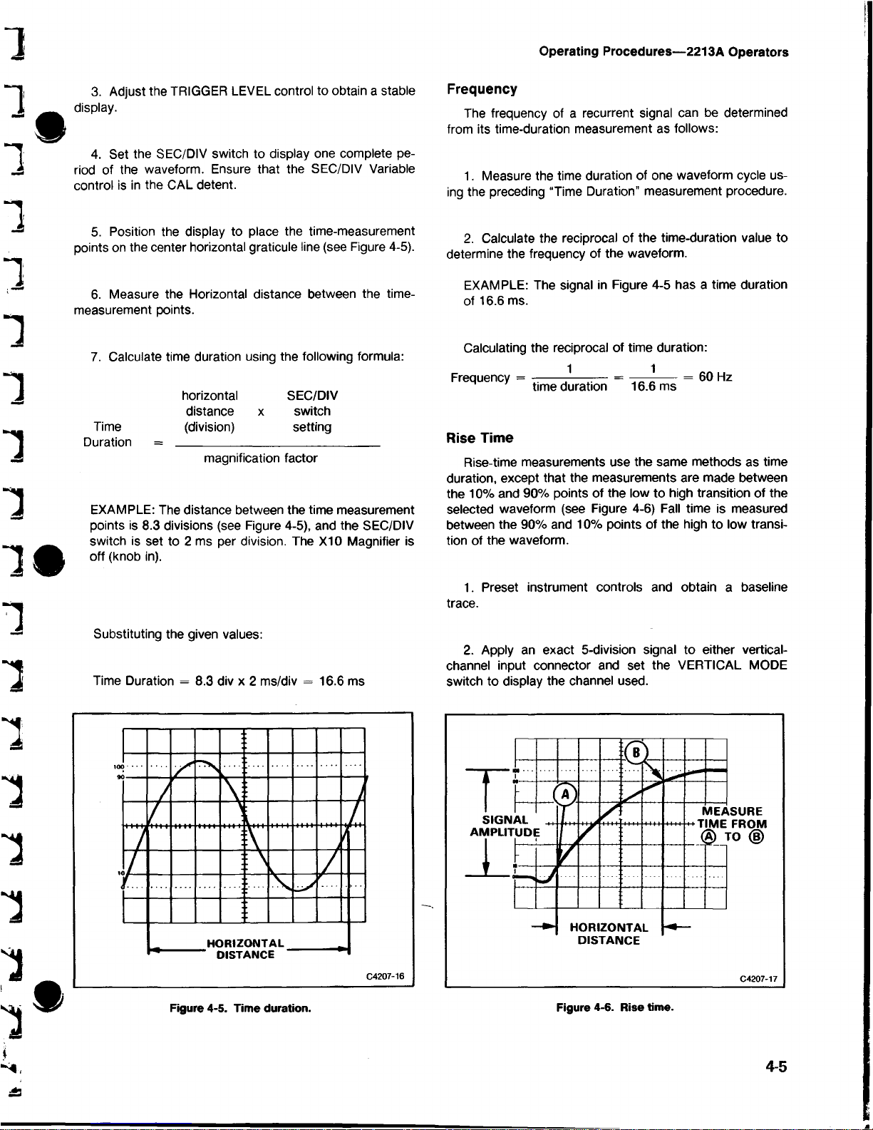
4. Set the SEC/DIV switch to display one complete pe
riod of the waveform. Ensure that the SEC/DIV Variable
control is in the CAL detent.
5. Position the display to place the time-measurement
points on the center horizontal graticule line (see Figure 4-5).
6. Measure the Horizontal distance between the time-
measurement points.
7. Calculate time duration using the following formula:
horizontal SEC/DIV
distance x switch
Time (division) setting
Duration =
_________________________
__
magnification factor
EXAMPLE: The distance between the time measurement
points is 8.3 divisions (see Figure 4-5), and the SEC/DIV
switch is set to 2 ms per division. The X I0 Magnifier is
off (knob in).
Substituting the given values:
Time Duration = 8.3 div x 2 ms/div = 16.6 ms
Frequency
The frequency of a recurrent signal can be determined
from its time-duration measurement as follows:
1. Measure the time duration of one waveform cycle us
ing the preceding “Time Duration” measurement procedure.
2. Calculate the reciprocal of the time-duration value to
determine the frequency of the waveform.
EXAMPLE: The signal in Figure 4-5 has a time duration
of 16.6 ms.
Calculating the reciprocal of time duration:
Frequency =
-----
—-— = ——-
--------
= 60 Hz
time duration 16.6 ms
Rise Time
Rise-time measurements use the same methods as time
duration, except that the measurements are made between
the 10% and 90% points of the low to high transition of the
selected waveform (see Figure 4-6) Fall time is measured
between the 90% and 10% points of the high to low transi
tion of the waveform.
1. Preset instrument controls and obtain a baseline
trace.
2. Apply an exact 5-division signal to either vertical-
channel input connector and set the VERTICAL MODE
switch to display the channel used.
4-5
Figure 4-5. Time duration.
Figure 4-6. Rise time.
Page 31

Operating Procedures—2213A Operators
3. Set the appropriate VOLTS/DIV switch and variable
control for an exact 5-division display.
5. Select BOTH VERTICAL MODE; then select either
ALT or CHOP, depending on the frequency of input signals.
4. Vertically position the trace so that the zero reference
of the waveform touches the 0% graticule line and the top of
the waveform touches the 100% graticule line.
5. Horizontally position the display so the 10% point on
the waveform intersects the second vertical graticule line.
6. If the two signals are of opposite polarity, press in the
Channel 2 INVERT button to invert the Channel 2 display
(signals may be of opposite polarity due to 180° phase
difference).
7. Adjust the TRIGGER LEVEL control for a stable
display.
6. Measure the horizontal distance between the 10%
and 90% points (between Points A and B of Figure 4-6) and
calculate the time duration using the following formula:
horizontal SEC/DIV
distance x switch
Rise (divisions) setting
Time = ________________________
magnification factor
Example: The horizontal distance between the 10% and
90% points is 5 divisions, and the SEC/DIV switch is set
to 1 fis per division. The XI0 magnifier knob is off (knob
in).
Substituting the given values in the formula:
Rise Time
5 div x 1 nsldiv
i
5 ns
8. Set the SEC/DIV switch to a sweep speed which pro
vides three or more divisions of horizontal separation be
tween the reference points on the two displays. Center each
of the displays vertically (see Figure 4-7)
9. Measure the horizontal difference between the two
signal reference points and calculate the time difference us
ing the following formula:
SEC/DIV horizontal
switch x difference
Time setting (divisions)
Difference = ________________________
magnification factor
EXAMPLE: The SEC/DIV switch is set to 50 ^s per divi
sion, the XI0 Magnifier is on (button out) and the hori
zontal difference between waveform measurement
points is 4.5 divisions.
Time Difference Between Pulses On Time-Related
Signals
The calibrated sweep speed and dual-trace features of
the 2213A allow measurement of the time difference be
tween two separate events. To measure time difference,
use the following procedure:
1. Preset instrument controls and obtain a baseline
trace, then set the TRIGGER SOURCE switch to CH 1.
2. Set both Input Coupling switches to the same posi
tion, depending on the type of input coupling desired.
3. Using either probes or cables with equal tyne delays,
connect a known reference signal to the Channel 1 input
and the comparison signal to the Channel 2 input.
4. Set both VOLTS/DIV switches for 4- or 5-division
displays.
Substituting the given values in the formula:
Time
Difference
50 Ats/div x 4.5 div
10
22.5 ns
Figure 4-7. Time difference between pulses on time-related
signals.
4-6
Page 32

Operating Procedures—2213A Operators
Phase Difference
In a similar manner to “Time Difference Between Two
Time-Related Pulses” phase comparison between two sig
nals of the same frequency can be made using the dual
trace feature of the 2213A. This method of phase difference
measurement can be used up to the frequency limit of the
vertical deflection system. To make a phase comparison,
use the following procedure:
1. Preset instrument controls and obtain a baseline
trace, then set the INT switch to CH 1.
2. Set both Input Coupling switches to the same posi
tion, depending on the type of input coupling desired.
CHANNEL 1 CHANNEL 2
MEASURE
TIME FROM
® TO ( |)
HORIZONTAL
DIFFERENCE
C4207-19
3. Using either probes or cables with equal time delays,
connect a known reference signal to the Channel 1 input
and the unknown signal to the Channel 2 input.
4. Select BOTH VERTICAL MODE; then select either
ALT or CHOP, depending on the frequency of input signals.
The reference signal should precede the comparison signal
in time.
5. If the two signals are of opposite polarity, press in
the Channel 2 INVERT button to invert the Channel 2
display.
Figure 4-8. Phase difference.
horizontal
Phase horizontal graticule
Difference = difference x
(divisions) calibration
(deg/div)
Example: The horizontal difference is 0.6 division with a
graticule calibration of 45° per division as shown in Fig
ure 4-8.
6. Set both VOLTS/DIV switches and both Variable
controls so the displays are equal in amplitude.
7. Adjust the TRIGGER LEVEL control for a stable
display.
8. Set the SEC/DIV switch to a sweep speed which
displays about one full cycle on the waveforms.
9. Position the displays and adjust the SEC/DIV Vari
able control so that one reference-signal cycle occupies ex
actly 8 horizontal graticule divisions at the 50% rise-time
points (see Figure 4-8). Each division of the graticule now
represents 45° of the cycle (360°
h- 8 divisions), and Jthe
horizontal graticule calibration can be stated as 45o/per
division.
10. Measure the horizontal difference between cor
responding points on the waveforms at a common horizon
tal graticule line (50% of rise time) and calculate the phase
difference using the following formula:
Substituting the given values into the phase difference
formula:
Phase difference = 0.6 div x 45°/div = 27°.
More accurate phase measurements can be made by us
ing the X I0 Magnifier function to increase the sweep speed
without changing the SEC/DIV Variable control setting.
EXAMPLE: If the sweep speed were increased 10 times
with the magnifier (XI0 Magnifier button out), the magni
fied horizontal graticule calibration would be 45°/division
divided by 10 (or 4.5°/division). Figure 4-9 shows the
same signals illustrated in Figure 4-8, but magnifying the
displays results in a horizontal difference of 6 divisions
between the two signals.
Substituting the given values in the phase difference
formula:
Phase difference = 6 div x 4.5°/div = 27°.
Page 33
Operating Procedures—2213A Operators
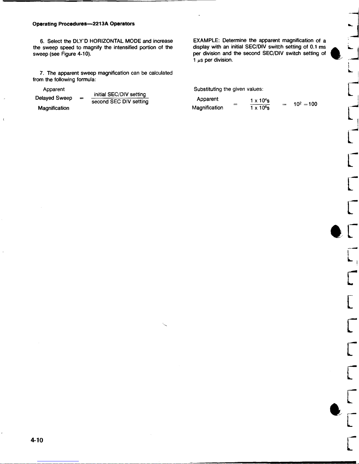
6. Select the DLY’D HORIZONTAL MODE and increase
the sweep speed to magnify the intensified portion of the
sweep (see Figure 4-10).
7. The apparent sweep magnification can be calculated
from the following formula:
Apparent
Delayed Sweep
Magnification
initial SEC/DIV setting
second SEC DIV setting
EXAMPLE: Determine the apparent magnification of a
display with an initial SEC/DIV switch setting of 0.1 ms
per division and the second SEC/DIV switch setting of
1 ixs per division.
Substituting the given values:
Apparent l x 1 0 4s
Magnification 1 x 10⁶s
102 =100
4-10
Page 34

Section 5—2213A Operators
OPTIONS AND
INTRODUCTION
This section contains a general description of instrument
options available at the time of publication of this manual.
Also included is a complete list (with Tektronix part number)
of standard accessories included with each instrument and
a partial list of optional accessories. Additional information
about instrument options, option availability, and other ac
cessories can be obtained either by consulting the current
Tektronix Product Catalog or by contacting your Tektronix
Field Office or representative.
OPTIONS
There are currently no options available for the 2213A.
INTERNATIONAL POWER CORDS
Instruments are shipped with the detachable power-cord
configuration ordered by the customer. Descriptive informa
tion about the international power-cords is provided in Sec
tion 2, “Preparation for Use”. The following list identifies the
Tektronix part numbers for the available power cords.
ACCESSORIES
STANDARD ACCESSORIES
The following standard accessories are provided with
each instrument.
Qty Description Order
2 Probes, 10X 1,5-meter length with
accessories ........................................ 010-6122-01
1 Power Cord
.........................................
161-0104-00
1 Operators Manual
...............................
070-4734-00
OPTIONAL ACCESSORIES
The following optional accessories are recommended for
use with the 2213A Oscilloscope.
Description Order
Service Manual
.........................................
070-4733-00
Protective Front Panel Cover
...................
200-2520-00
Cord Wrap and Storage Pouch
............
016-0677-00
Protective Front Panel Cover, Cord
Wrap, and Storage Pouch
.........................
020-0672-00
Carrying Strap......................................... 346-0199-00
Carrying Case
...........................................
016-0694-00
Low-Cost, General-Purpose Camera .. . C-5C Option 04
Description Order
Universal Euro 10-16 A, 50 Hz
..................
020-0859-00
UK 240 V/13A, 50 Hz
................................
020-0860-00
Australian 240 V/10A, 50 H z
......................
020-0861-00
North American 240 V/15A, 60 H z
............
020-0862-00
Switzerland 220 V/10A, 50 Hz
..................
020-0863-00
Rackmount Adapter Kit
..................
016-0466-0C
Model 200C
SCOPE-MOBILE CART—Occupies less
than 18 inches of aisle space, with stor
age area in base
....................................
REV MAR 1984
5-1
Page 35

Limited license: Tektronix, Inc. grants permission
to reproduce this drawing as a visual aid for use
in instrument operator training.
Page 36

2213A Operators
Ife ktronix
COM M IT TED TO EX CE LLENCE
b -
I
Copyright © 1983, Tektronix, Inc.
All rights reserved.
Page 37

 Loading...