

Page 1

User Manual
Grass Valley Model 2200
Digital Production Switcher
Software Release 5.3
071-0156-00
First Printing: January, 1994
Revised Printing: February, 1998
Page 2

Telephone
Numbers
North America
(800) 547-8949
Fax: (530) 478-3181
Elsewhere
Distributor or sales office
from which equipment was
purchased.
Web Addresses
Grass Valley Email
Support
GVGSERVICE@tek.com
Grass Valley W eb Page
http://www.tek.com/Grass_
Valley
Tektronix W eb Site
http://www.tek.com
Postal Addresses
Mail
Tektronix Grass Valley
Products
P.O. Box 1114
Grass Valley, CA 95945
Shipping
Tektronix Grass Valley
Products
400 Providence Mine Rd.,
Nevada City, CA 95959
Customer Support
Tektronix Grass Valley Products is committed to providing the
most responsive and professional product support available. We
have a fully staffed, highly trained support team ready to respond
to anything from a simple question to an emergency repair. Support is available via telephone or email. For new and updated customer support documents, as well as new product information,
check the Tektronix web site and Grass Valley’s web page.
Copyright © Tektronix, Inc. All rights reserved. Printed in U.S.A.
Tektronix products are covered by U.S. and foreign patents, issued and pending.
Information in this publication supersedes that in all previously published material. Specifications and price change privileges reserved. TEKTRONIX, TEK, Grass
Valley Group, Borderline, E-MEM, TEN-X, Wavelink, and are registered
trademarks, and Air Link, Auto Match, Doubletake, E-Disk, Eagle V, Emphasys,
EZ-Link, 409, Grass Valley, Horizon, Jogger, Kadenza, Kaleidoscope, K-Mask,
Key-Layer, Key-Link, Krystal, MASTER System, Master 21, MAX, Omni-Key, Performer, Programmed Motion, Silhouette, Softset, SqueezeBack, Streamline, Super
Edit, TEN-20, 20-TEN, Trace, TrailBlazer, VideoDesktop, Flex-Time, and XEDL are
trademarks of Tektronix, Inc. P.O. Box 1000 Wilsonville, OR 97070-1000 U.S.A.
The information in this manual is furnished for informational use only, is subject
to change without notice, and should not be construed as a commitment by Tektronix, Inc. Tektronix assumes no responsibility or liability for any errors or inaccuracies that may appear in this publication.
Tektronix, Inc., Video and Networking Division, P.O. Box 1114 Grass Valley, California 95945 U.S.A.
Page 3

Contents
Preface
Welcome to the Model 2200 . . . . . . . . . . . . . . . . . . . . . . . . . . . . . . . . . . . . . xi
Organization of This Manual . . . . . . . . . . . . . . . . . . . . . . . . . . . . . . . . . . . . xi
Related Documents . . . . . . . . . . . . . . . . . . . . . . . . . . . . . . . . . . . . . . . . . . . xii
How to use this manual . . . . . . . . . . . . . . . . . . . . . . . . . . . . . . . . . . . . . . . . xii
Conventions used in this manual . . . . . . . . . . . . . . . . . . . . . . . . . . . . . . . . xiv
Button References . . . . . . . . . . . . . . . . . . . . . . . . . . . . . . . . . . . . . . . . . xiv
Panel Knob References . . . . . . . . . . . . . . . . . . . . . . . . . . . . . . . . . . . . . xiv
Menu References . . . . . . . . . . . . . . . . . . . . . . . . . . . . . . . . . . . . . . . . . . xiv
Soft Button and Soft Knob References . . . . . . . . . . . . . . . . . . . . . . . . xv
Section 1 — System Overview
Basic Architecture . . . . . . . . . . . . . . . . . . . . . . . . . . . . . . . . . . . . . . . . . . . . . 1-1
Standard Features . . . . . . . . . . . . . . . . . . . . . . . . . . . . . . . . . . . . . . . . . . . . . 1-2
Optional Features . . . . . . . . . . . . . . . . . . . . . . . . . . . . . . . . . . . . . . . . . . . . . 1-3
Physical Description . . . . . . . . . . . . . . . . . . . . . . . . . . . . . . . . . . . . . . . . . . . 1-4
Signal Processor Frame . . . . . . . . . . . . . . . . . . . . . . . . . . . . . . . . . . . . . 1-4
Power Supplies . . . . . . . . . . . . . . . . . . . . . . . . . . . . . . . . . . . . . . . . . . . 1-4
Control Panel . . . . . . . . . . . . . . . . . . . . . . . . . . . . . . . . . . . . . . . . . . . . . 1-6
Video and Key Inputs and Outputs . . . . . . . . . . . . . . . . . . . . . . . . . . 1-8
Inputs . . . . . . . . . . . . . . . . . . . . . . . . . . . . . . . . . . . . . . . . . . . . . . . . 1-8
Outputs . . . . . . . . . . . . . . . . . . . . . . . . . . . . . . . . . . . . . . . . . . . . . . 1-9
Functional Description . . . . . . . . . . . . . . . . . . . . . . . . . . . . . . . . . . . . . . . . 1-10
General Overview . . . . . . . . . . . . . . . . . . . . . . . . . . . . . . . . . . . . . . . . 1-10
Video Processing . . . . . . . . . . . . . . . . . . . . . . . . . . . . . . . . . . . . . . . . . 1-10
iii
Page 4

Contents
Section 2 — Startup and Configuration
Description of Options . . . . . . . . . . . . . . . . . . . . . . . . . . . . . . . . . . . . . . . . 1-14
Chromatte Advanced Chroma Keyer . . . . . . . . . . . . . . . . . . . . . . . . 1-14
BORDERLINE Key Edge Generation . . . . . . . . . . . . . . . . . . . . . . . . 1-14
Secondary Wipe Generator . . . . . . . . . . . . . . . . . . . . . . . . . . . . . . . . 1-14
Effects Send . . . . . . . . . . . . . . . . . . . . . . . . . . . . . . . . . . . . . . . . . . . . . . 1-15
Look Ahead Preview . . . . . . . . . . . . . . . . . . . . . . . . . . . . . . . . . . . . . . 1-15
Tally Relay Frame . . . . . . . . . . . . . . . . . . . . . . . . . . . . . . . . . . . . . . . . 1-15
Remote Aux Bus . . . . . . . . . . . . . . . . . . . . . . . . . . . . . . . . . . . . . . . . . . 1-16
Timed Aux Output . . . . . . . . . . . . . . . . . . . . . . . . . . . . . . . . . . . . . . . 1-16
Powering Up . . . . . . . . . . . . . . . . . . . . . . . . . . . . . . . . . . . . . . . . . . . . . . . . . 2-1
Booting-Up . . . . . . . . . . . . . . . . . . . . . . . . . . . . . . . . . . . . . . . . . . . . . . . 2-2
Software Setup . . . . . . . . . . . . . . . . . . . . . . . . . . . . . . . . . . . . . . . . . . . . . . . . 2-2
The Configuration Menu . . . . . . . . . . . . . . . . . . . . . . . . . . . . . . . . . . . 2-2
Configuration Sub-Menus . . . . . . . . . . . . . . . . . . . . . . . . . . . . . . . 2-4
Setting User Preferences . . . . . . . . . . . . . . . . . . . . . . . . . . . . . . . . . . . . 2-9
Setting Keyer Preferences . . . . . . . . . . . . . . . . . . . . . . . . . . . . . . . . . . 2-10
Setting Preview Preferences . . . . . . . . . . . . . . . . . . . . . . . . . . . . . . . . 2-12
Beeper Preferences . . . . . . . . . . . . . . . . . . . . . . . . . . . . . . . . . . . . . . . . 2-16
Defining System Defaults . . . . . . . . . . . . . . . . . . . . . . . . . . . . . . . . . . 2-17
E-MEM Preferences . . . . . . . . . . . . . . . . . . . . . . . . . . . . . . . . . . . . . . . 2-18
Setting System Parameters . . . . . . . . . . . . . . . . . . . . . . . . . . . . . . . . . 2-19
Using Field Dominance . . . . . . . . . . . . . . . . . . . . . . . . . . . . . . . . 2-20
Setting the System Clock . . . . . . . . . . . . . . . . . . . . . . . . . . . . . . . . . . . 2-22
Configuring Switcher Inputs . . . . . . . . . . . . . . . . . . . . . . . . . . . . . . . 2-24
Inputs . . . . . . . . . . . . . . . . . . . . . . . . . . . . . . . . . . . . . . . . . . . . . . . . . . . 2-25
Setting Analog Video Inputs . . . . . . . . . . . . . . . . . . . . . . . . . . . . . . . 2-26
Setting Analog Key Inputs . . . . . . . . . . . . . . . . . . . . . . . . . . . . . . . . . 2-27
Setting Analog Input Timing . . . . . . . . . . . . . . . . . . . . . . . . . . . . . . . 2-28
Mapping Crosspoints . . . . . . . . . . . . . . . . . . . . . . . . . . . . . . . . . . . . . 2-29
Naming Crosspoint Buttons . . . . . . . . . . . . . . . . . . . . . . . . . . . . . . . . 2-31
Formatting Chroma Key Inputs . . . . . . . . . . . . . . . . . . . . . . . . . . . . . 2-32
Assigning GPI Inputs . . . . . . . . . . . . . . . . . . . . . . . . . . . . . . . . . . . . . 2-33
Configuring Outputs . . . . . . . . . . . . . . . . . . . . . . . . . . . . . . . . . . . . . . 2-36
Setting Output Resolution and Dither . . . . . . . . . . . . . . . . . . . . . . . 2-37
Configuring External Interfaces . . . . . . . . . . . . . . . . . . . . . . . . . . . . . 2-39
iv
Page 5

Setting Editor Port Parameters . . . . . . . . . . . . . . . . . . . . . . . . . . . . . 2-40
Configuring GPI Outputs . . . . . . . . . . . . . . . . . . . . . . . . . . . . . . . . . . 2-41
DPM Configurations . . . . . . . . . . . . . . . . . . . . . . . . . . . . . . . . . . . . . . 2-42
The Video Connection (Aux Buses and Return Inputs) . . . . . 2-42
DPM Capabilities (Fixed and Pooled) . . . . . . . . . . . . . . . . . . . . 2-43
Control Connection . . . . . . . . . . . . . . . . . . . . . . . . . . . . . . . . . . . 2-47
Configuring the DPM Interface . . . . . . . . . . . . . . . . . . . . . . . . . . . . . 2-48
Kaleidoscope Source Button Mapping . . . . . . . . . . . . . . . . . . . . . . . 2-51
Mapping DPM Aux Buses . . . . . . . . . . . . . . . . . . . . . . . . . . . . . . . . . 2-52
Example 1: Switcher-to-Kaleidoscope Configuration . . . . . . . 2-54
Example 2: Switcher-to-Kaleidoscope Configuration . . . . . . . 2-55
Mapping DPM Inputs . . . . . . . . . . . . . . . . . . . . . . . . . . . . . . . . . . . . . 2-57
Mapping DPM Returns . . . . . . . . . . . . . . . . . . . . . . . . . . . . . . . . 2-58
Configuring the Peripheral Interface . . . . . . . . . . . . . . . . . . . . . . . . 2-60
Assigning Peripheral Trigger . . . . . . . . . . . . . . . . . . . . . . . . . . . 2-60
Formatting Aux Buses . . . . . . . . . . . . . . . . . . . . . . . . . . . . . . . . . . . . 2-63
Section 3 — Switcher Concepts
Clear Working Buffer . . . . . . . . . . . . . . . . . . . . . . . . . . . . . . . . . . . . . . . . . . 3-2
Clear Work Buffer Operation Modes . . . . . . . . . . . . . . . . . . . . . . . . . 3-3
Auto Delegation . . . . . . . . . . . . . . . . . . . . . . . . . . . . . . . . . . . . . . . . . . . . . . 3-4
Crosspoint Bus . . . . . . . . . . . . . . . . . . . . . . . . . . . . . . . . . . . . . . . . . . . . . . . 3-5
Transitions . . . . . . . . . . . . . . . . . . . . . . . . . . . . . . . . . . . . . . . . . . . . . . . . . . . 3-6
Cut Transition . . . . . . . . . . . . . . . . . . . . . . . . . . . . . . . . . . . . . . . . . . . . 3-6
Mix Transition . . . . . . . . . . . . . . . . . . . . . . . . . . . . . . . . . . . . . . . . . . . . 3-6
Wipe Transition . . . . . . . . . . . . . . . . . . . . . . . . . . . . . . . . . . . . . . . . . . . 3-8
Keys . . . . . . . . . . . . . . . . . . . . . . . . . . . . . . . . . . . . . . . . . . . . . . . . . . . . . . . . 3-9
Luminance Key . . . . . . . . . . . . . . . . . . . . . . . . . . . . . . . . . . . . . . . . . . . 3-9
Linear Key . . . . . . . . . . . . . . . . . . . . . . . . . . . . . . . . . . . . . . . . . . . . . . . 3-11
Preset Pattern Key . . . . . . . . . . . . . . . . . . . . . . . . . . . . . . . . . . . . . . . . 3-11
Shaped and Unshaped Video . . . . . . . . . . . . . . . . . . . . . . . . . . . . . . . . . . 3-12
Input Shaped and Unshaped Video . . . . . . . . . . . . . . . . . . . . . . . . . 3-13
Output Shaped and Unshaped Video . . . . . . . . . . . . . . . . . . . . . . . 3-13
Super Black . . . . . . . . . . . . . . . . . . . . . . . . . . . . . . . . . . . . . . . . . . . . . . . . . 3-14
Chroma Key . . . . . . . . . . . . . . . . . . . . . . . . . . . . . . . . . . . . . . . . . . . . . . . . . 3-15
Contents
v
Page 6

Contents
Section 4 — Switcher Operations
Coring . . . . . . . . . . . . . . . . . . . . . . . . . . . . . . . . . . . . . . . . . . . . . . . . . . . . . . 3-16
Layering . . . . . . . . . . . . . . . . . . . . . . . . . . . . . . . . . . . . . . . . . . . . . . . . . . . . 3-17
E-MEM Effects Memory . . . . . . . . . . . . . . . . . . . . . . . . . . . . . . . . . . . . . . . 3-18
Effects and Keyframes . . . . . . . . . . . . . . . . . . . . . . . . . . . . . . . . . . . . . 3-18
Enables and Delegates . . . . . . . . . . . . . . . . . . . . . . . . . . . . . . . . . . . . . 3-19
Enables and Delegates Button Tallies . . . . . . . . . . . . . . . . . . . . 3-20
Keyframing / Timelines / Effects Editing . . . . . . . . . . . . . . . . . . . . . . . 3-21
Effects Editing Definitions . . . . . . . . . . . . . . . . . . . . . . . . . . . . . . . . . 3-21
Timeline Menu . . . . . . . . . . . . . . . . . . . . . . . . . . . . . . . . . . . . . . . . . . . 3-22
Effects Send (Option) . . . . . . . . . . . . . . . . . . . . . . . . . . . . . . . . . . . . . . . . . 3-23
Frame Store (Option) . . . . . . . . . . . . . . . . . . . . . . . . . . . . . . . . . . . . . . . . . 3-24
Mask Store (Option) . . . . . . . . . . . . . . . . . . . . . . . . . . . . . . . . . . . . . . . . . . 3-25
About this Section . . . . . . . . . . . . . . . . . . . . . . . . . . . . . . . . . . . . . . . . . . . . . 4-1
Starting Conditions . . . . . . . . . . . . . . . . . . . . . . . . . . . . . . . . . . . . . . . . . . . . 4-2
Switcher Hardware Setup . . . . . . . . . . . . . . . . . . . . . . . . . . . . . . . . . . . 4-2
Clearing the Switcher . . . . . . . . . . . . . . . . . . . . . . . . . . . . . . . . . . . . . . 4-4
Transitions - Mix/Effects Bus Operations . . . . . . . . . . . . . . . . . . . . . . . . . 4-6
Background Cut . . . . . . . . . . . . . . . . . . . . . . . . . . . . . . . . . . . . . . . . . . . 4-6
Background Mix . . . . . . . . . . . . . . . . . . . . . . . . . . . . . . . . . . . . . . . . . . . 4-9
Wipe Operations . . . . . . . . . . . . . . . . . . . . . . . . . . . . . . . . . . . . . . . . . . . . . 4-11
Background Wipe . . . . . . . . . . . . . . . . . . . . . . . . . . . . . . . . . . . . . . . . 4-11
Pattern Mixing . . . . . . . . . . . . . . . . . . . . . . . . . . . . . . . . . . . . . . . . 4-15
Learning User Wipes . . . . . . . . . . . . . . . . . . . . . . . . . . . . . . . . . . 4-16
Fade to Black . . . . . . . . . . . . . . . . . . . . . . . . . . . . . . . . . . . . . . . . . . . . . 4-19
Setting Transition Rates . . . . . . . . . . . . . . . . . . . . . . . . . . . . . . . . . . . 4-20
Background and Matte Generator Operations . . . . . . . . . . . . . . . . 4-22
Matte Selection . . . . . . . . . . . . . . . . . . . . . . . . . . . . . . . . . . . . . . . 4-22
User Defined Wash (4000-2B only) . . . . . . . . . . . . . . . . . . . . . . 4-24
Super Black . . . . . . . . . . . . . . . . . . . . . . . . . . . . . . . . . . . . . . . . . . 4-25
Luminance and Linear Keying Operations . . . . . . . . . . . . . . . . . . . . . . . 4-26
Key Transition . . . . . . . . . . . . . . . . . . . . . . . . . . . . . . . . . . . . . . . . . . . 4-31
Preset Pattern Keying Operations . . . . . . . . . . . . . . . . . . . . . . . . . . . . . . 4-32
vi
Page 7

Contents
Layered Mode Operations . . . . . . . . . . . . . . . . . . . . . . . . . . . . . . . . . . . . . 4-35
Chroma Keying Operations . . . . . . . . . . . . . . . . . . . . . . . . . . . . . . . . . . . 4-36
Auto Chroma Keying Procedure . . . . . . . . . . . . . . . . . . . . . . . . . . . . 4-37
Auto Setup . . . . . . . . . . . . . . . . . . . . . . . . . . . . . . . . . . . . . . . . . . . 4-39
Basic Manual Adjustment . . . . . . . . . . . . . . . . . . . . . . . . . . . . . . 4-40
Optimization Adjustments . . . . . . . . . . . . . . . . . . . . . . . . . . . . . 4-41
E-MEM (Effects Memory) Operations . . . . . . . . . . . . . . . . . . . . . . . . . . . 4-46
New Operational Mode Available – Version 5.1 and later . . . . . . 4-47
Normal Mode . . . . . . . . . . . . . . . . . . . . . . . . . . . . . . . . . . . . . . . . 4-47
Learn A Register . . . . . . . . . . . . . . . . . . . . . . . . . . . . . . . . . . . . . . 4-48
Recall A Register . . . . . . . . . . . . . . . . . . . . . . . . . . . . . . . . . . . . . . 4-49
300 Style Mode – 3-M/E Switchers Only . . . . . . . . . . . . . . . . . . . . . 4-50
Operational Defaults in Either Mode . . . . . . . . . . . . . . . . . . . . . . . . 4-50
Setup . . . . . . . . . . . . . . . . . . . . . . . . . . . . . . . . . . . . . . . . . . . . . . . . . . . 4-51
Basic E-MEM Operations . . . . . . . . . . . . . . . . . . . . . . . . . . . . . . . . . . 4-51
Enabling E-MEM Register Levels . . . . . . . . . . . . . . . . . . . . . . . 4-51
Learn Enables . . . . . . . . . . . . . . . . . . . . . . . . . . . . . . . . . . . . . . . . 4-51
Recall Enables . . . . . . . . . . . . . . . . . . . . . . . . . . . . . . . . . . . . . . . . 4-52
Storing an Effect . . . . . . . . . . . . . . . . . . . . . . . . . . . . . . . . . . . . . . 4-52
Recalling an Effect . . . . . . . . . . . . . . . . . . . . . . . . . . . . . . . . . . . . 4-53
Learning Effects Dissolve Transitions . . . . . . . . . . . . . . . . . . . . 4-53
E-MEM Learn Sequence Operations . . . . . . . . . . . . . . . . . . . . . 4-54
Undo Function . . . . . . . . . . . . . . . . . . . . . . . . . . . . . . . . . . . . . . . . . . . 4-55
Keyframe Operations . . . . . . . . . . . . . . . . . . . . . . . . . . . . . . . . . . . . . . . . . 4-56
Setup . . . . . . . . . . . . . . . . . . . . . . . . . . . . . . . . . . . . . . . . . . . . . . . . . . . 4-56
Basic Editing . . . . . . . . . . . . . . . . . . . . . . . . . . . . . . . . . . . . . . . . . . . . . 4-56
Learn Keyframes . . . . . . . . . . . . . . . . . . . . . . . . . . . . . . . . . . . . . 4-57
Advanced Keyframe Editing . . . . . . . . . . . . . . . . . . . . . . . . . . . . . . . 4-58
Version 5.2 and later software changes . . . . . . . . . . . . . . . . . . . 4-60
Working With Keyframe Timelines . . . . . . . . . . . . . . . . . . . . . . 4-62
Setting and Adjusting Start Times . . . . . . . . . . . . . . . . . . . . . . . 4-64
Zoom and Pan Timeline Effects . . . . . . . . . . . . . . . . . . . . . . . . . 4-65
Cut, Copy, and Paste Keyframes . . . . . . . . . . . . . . . . . . . . . . . . 4-67
Effects Editing with Get and Put . . . . . . . . . . . . . . . . . . . . . . . . 4-68
Constant Duration Mode . . . . . . . . . . . . . . . . . . . . . . . . . . . . . . 4-69
Using Path Types To Change An Effect . . . . . . . . . . . . . . . . . . 4-69
Effects Send Operations (Option) . . . . . . . . . . . . . . . . . . . . . . . . . . . . . . . 4-71
Setup . . . . . . . . . . . . . . . . . . . . . . . . . . . . . . . . . . . . . . . . . . . . . . . . . . . 4-71
Effects Send Looping Mode . . . . . . . . . . . . . . . . . . . . . . . . . . . . . . . . 4-73
Effects Send Non-Looping Mode . . . . . . . . . . . . . . . . . . . . . . . . . . . 4-73
vii
Page 8

Contents
Frame Store Operations (Option) . . . . . . . . . . . . . . . . . . . . . . . . . . . . . . . 4-74
Setup . . . . . . . . . . . . . . . . . . . . . . . . . . . . . . . . . . . . . . . . . . . . . . . . . . . 4-74
Output Routing . . . . . . . . . . . . . . . . . . . . . . . . . . . . . . . . . . . . . . . . . . 4-74
Still Image Storage . . . . . . . . . . . . . . . . . . . . . . . . . . . . . . . . . . . . . . . . 4-75
Building A Recursive Effect . . . . . . . . . . . . . . . . . . . . . . . . . . . . 4-75
Video and Key . . . . . . . . . . . . . . . . . . . . . . . . . . . . . . . . . . . . . . . . 4-76
Mask Store . . . . . . . . . . . . . . . . . . . . . . . . . . . . . . . . . . . . . . . . . . . 4-76
Freeze Mode . . . . . . . . . . . . . . . . . . . . . . . . . . . . . . . . . . . . . . . . . . . . . 4-76
Frame Store Field Modes . . . . . . . . . . . . . . . . . . . . . . . . . . . . . . . . . . 4-77
Field 1 / Field 2 . . . . . . . . . . . . . . . . . . . . . . . . . . . . . . . . . . . . . . . 4-77
Grab Field / 4 Field . . . . . . . . . . . . . . . . . . . . . . . . . . . . . . . . . . . 4-77
Mode . . . . . . . . . . . . . . . . . . . . . . . . . . . . . . . . . . . . . . . . . . . . . . . . . . . 4-77
Dropshadow Mode . . . . . . . . . . . . . . . . . . . . . . . . . . . . . . . . . . . . . . . 4-78
Repositioning . . . . . . . . . . . . . . . . . . . . . . . . . . . . . . . . . . . . . . . . . . . . 4-78
Mosaics . . . . . . . . . . . . . . . . . . . . . . . . . . . . . . . . . . . . . . . . . . . . . . . . . 4-78
Pseudo Color . . . . . . . . . . . . . . . . . . . . . . . . . . . . . . . . . . . . . . . . . . . . 4-79
Filter . . . . . . . . . . . . . . . . . . . . . . . . . . . . . . . . . . . . . . . . . . . . . . . . . . . . 4-79
Crop . . . . . . . . . . . . . . . . . . . . . . . . . . . . . . . . . . . . . . . . . . . . . . . . . . . . 4-79
Mask Store Option . . . . . . . . . . . . . . . . . . . . . . . . . . . . . . . . . . . . . . . . 4-79
Masking a Key . . . . . . . . . . . . . . . . . . . . . . . . . . . . . . . . . . . . . . . . 4-81
Softening a Mask Store Image . . . . . . . . . . . . . . . . . . . . . . . . . . 4-82
Mask Draw Option . . . . . . . . . . . . . . . . . . . . . . . . . . . . . . . . . . . . . . . 4-82
Setting up the Mask Draw . . . . . . . . . . . . . . . . . . . . . . . . . . . . . . 4-83
Mask Draw Using Key Channel . . . . . . . . . . . . . . . . . . . . . . . . . 4-84
Floppy Disk Drive Operations . . . . . . . . . . . . . . . . . . . . . . . . . . . . . . . . . 4-86
Format Diskettes . . . . . . . . . . . . . . . . . . . . . . . . . . . . . . . . . . . . . . . . . 4-86
Creating Directories and Files . . . . . . . . . . . . . . . . . . . . . . . . . . . . . . 4-87
Store and Name An E-MEM File . . . . . . . . . . . . . . . . . . . . . . . . 4-87
Store and Name A Configuration File . . . . . . . . . . . . . . . . . . . . 4-88
Loading – Recalling E-MEM Files from Disk . . . . . . . . . . . . . . 4-89
Loading (Recalling) Configuration Files from Disk . . . . . . . . 4-90
Viewing (Listing) Files and Directories . . . . . . . . . . . . . . . . . . . 4-90
Deleting Files and Directories . . . . . . . . . . . . . . . . . . . . . . . . . . . 4-91
viii
Page 9

Appendix A — Shaped and Unshaped Video
Introduction . . . . . . . . . . . . . . . . . . . . . . . . . . . . . . . . . . . . . . . . . . . . . . . . . A-1
What are Shaped and Unshaped Video? . . . . . . . . . . . . . . . . . . . . . . . . A-1
Input Shaped and Unshaped Video . . . . . . . . . . . . . . . . . . . . . . . . . . . . . A-2
Configuring the Input . . . . . . . . . . . . . . . . . . . . . . . . . . . . . . . . . . . . . A-3
Examples of Operation With Shaped & Unshaped Fill Video . . . . . . . A-4
Correct Input Configuration . . . . . . . . . . . . . . . . . . . . . . . . . . . . . . . A-6
Correct Operation With Shaped Fill Video . . . . . . . . . . . . . . . A-6
Correct Operation With Unshaped Fill Video . . . . . . . . . . . . . A-7
Incorrect Input Configuration . . . . . . . . . . . . . . . . . . . . . . . . . . . . . . A-9
Incorrect Operation With Shaped Fill Video . . . . . . . . . . . . . . A-9
Incorrect Operation With Unshaped Fill Video . . . . . . . . . . . A-10
Output Shaped and Unshaped Video . . . . . . . . . . . . . . . . . . . . . . . . . . A-13
For the Model 3000: . . . . . . . . . . . . . . . . . . . . . . . . . . . . . . . . . . A-13
For the Model 4000 or Model 2200: . . . . . . . . . . . . . . . . . . . . . A-14
Installation Considerations . . . . . . . . . . . . . . . . . . . . . . . . . . . . . . . . . . . A-16
Contents
Appendix B — Keyframe Facts
Keyframe Timelines . . . . . . . . . . . . . . . . . . . . . . . . . . . . . . . . . . . . . . . . . . . B-1
Master Timeline . . . . . . . . . . . . . . . . . . . . . . . . . . . . . . . . . . . . . . . . . . . B-1
Enables and Delegates . . . . . . . . . . . . . . . . . . . . . . . . . . . . . . . . . . . . . . . . . B-2
Keyframe Path Control . . . . . . . . . . . . . . . . . . . . . . . . . . . . . . . . . . . . . . . . B-4
Tension, Continuity, and Bias Controls . . . . . . . . . . . . . . . . . . . . . . . B-4
Path Vectors . . . . . . . . . . . . . . . . . . . . . . . . . . . . . . . . . . . . . . . . . . B-5
Tension Control . . . . . . . . . . . . . . . . . . . . . . . . . . . . . . . . . . . . . . . B-6
Continuity Control . . . . . . . . . . . . . . . . . . . . . . . . . . . . . . . . . . . . . B-9
Bias Control . . . . . . . . . . . . . . . . . . . . . . . . . . . . . . . . . . . . . . . . . . B-12
ix
Page 10

Contents
Appendix C — Super Black
Glossary
Index
Definition of Super Black . . . . . . . . . . . . . . . . . . . . . . . . . . . . . . . . . . . . . . C-1
Objective . . . . . . . . . . . . . . . . . . . . . . . . . . . . . . . . . . . . . . . . . . . . . . . . . . . . C-1
Limitations . . . . . . . . . . . . . . . . . . . . . . . . . . . . . . . . . . . . . . . . . . . . . . . . . . C-1
Usage . . . . . . . . . . . . . . . . . . . . . . . . . . . . . . . . . . . . . . . . . . . . . . . . . . . . . . . C-2
Using the Super Black Output . . . . . . . . . . . . . . . . . . . . . . . . . . . . . . . . . . C-2
Generating Super Black . . . . . . . . . . . . . . . . . . . . . . . . . . . . . . . . . . . . C-3
First Method . . . . . . . . . . . . . . . . . . . . . . . . . . . . . . . . . . . . . . . . . C-4
Second Method . . . . . . . . . . . . . . . . . . . . . . . . . . . . . . . . . . . . . . . C-4
Reconstructing the Signal . . . . . . . . . . . . . . . . . . . . . . . . . . . . . . . . . . C-5
x
Page 11

Preface
Welcome to the Model 2200
This manual is intended to provide you, the video switching
system operator, with the information you need for operating this
Model 2200 Digital Production Switcher.
Organization of This Manual
This manual is organized as follows:
Section 1, System Overview
it is operated via the control panel.
Section 2, Startup and Configuration
the system and verifying its operating parameters, including
software configuration setups.
Section 3, Switcher Concepts
switcher operating concepts.
Section 4, Switcher Operations
basic switcher operations.
Appendices
Glossary
Index
– Describes the switcher and how
– Describes turning on
– Describes basic and advanced
– Step-by-step procedures on
xi
Page 12

Preface
Related Documents
The following manuals comprise the entire set that may be used
with the Model 2200 series switcher.
•
Operation Reference
•
Installation and Service
•
Model 2200/4000
Parts List
• Model 2200 Control Panel
• Model 2200/4000
•
There are also various Options Manuals, Application Notes, Field
Mod Notes, and Release Notes available for the Model 2200 and
other Grass Valley products. These documents are listed on the
Grass Valley web page
the back side of the Title Page) or you can contact your Grass
Valley Customer Service Representative for ordering information.
How To Use This Manual
Begin by reading the System Overview section so that you will be
familiar with the basic terminology used in this manual and the
structure of the hardware/software system.
Next, turn on the system as described in the Startup and
Configuration section and verify the switcher parameters set up
for your site or studio. It is assumed that the system has been
installed according to your studio plan and that all inputs and
outputs are connected properly.
Drawings Manual
Serial Protocols Manual
(see Customer Service Information on
Drawings Manual
xii
Page 13

How To Use This Manual
If you are an experienced switcher operator, you may choose to go
directly from Startup to operating the switcher, and refer to the
Control Panel Descriptions section in the
manual only when you need to know more about the operation of
a specific control. Experienced operators may also wish to refer to
some parts of Section 4 — Switcher Operations, to learn about
topics such as Chroma Keying, Effects Send, and how to set up
keyframes (a set of switcher parameters stored in an E-MEM
register).
If you are not an experienced operator, you should read or scan
this entire guide. You should first read Section 1 — System
Overview and Section 3 — Switcher Concepts to learn switcher
“basics.” Next, review the Startup and Configuration section to
get a feel for the switcher setups and configurations. Finally,
practice with and use the task-oriented procedures presented in
the Switcher Operations section that apply to your operations on
the switcher.
To quickly locate specific areas of interest, refer to the “master”
Table of Contents in the front of the manual, or the “local” Table
of Contents located at the front of each manual section.
Operation Reference
If you have any comments about this manual, we would like to
hear from you. Please write to:
Tektronix, Inc.
Grass Valley Products
Technical Publications Department
PO Box 1114
Grass Valley, CA 95945
xiii
Page 14

Preface
LUM
Conventions used in this manual
The following graphical and typestyle conventions are used
throughout this manual.
Button References
A control panel button is shown as follows:
Panel Knob References
Similarly, a control panel knob is shown as follows:
AUTO
SETUP
xiv
Menu References
Many Model 4000 features may be accessed via the menu display
and its associated “soft” buttons and “soft” knobs. The term “soft”
means that the function of the button or knob is assigned via the
currently displayed menu.
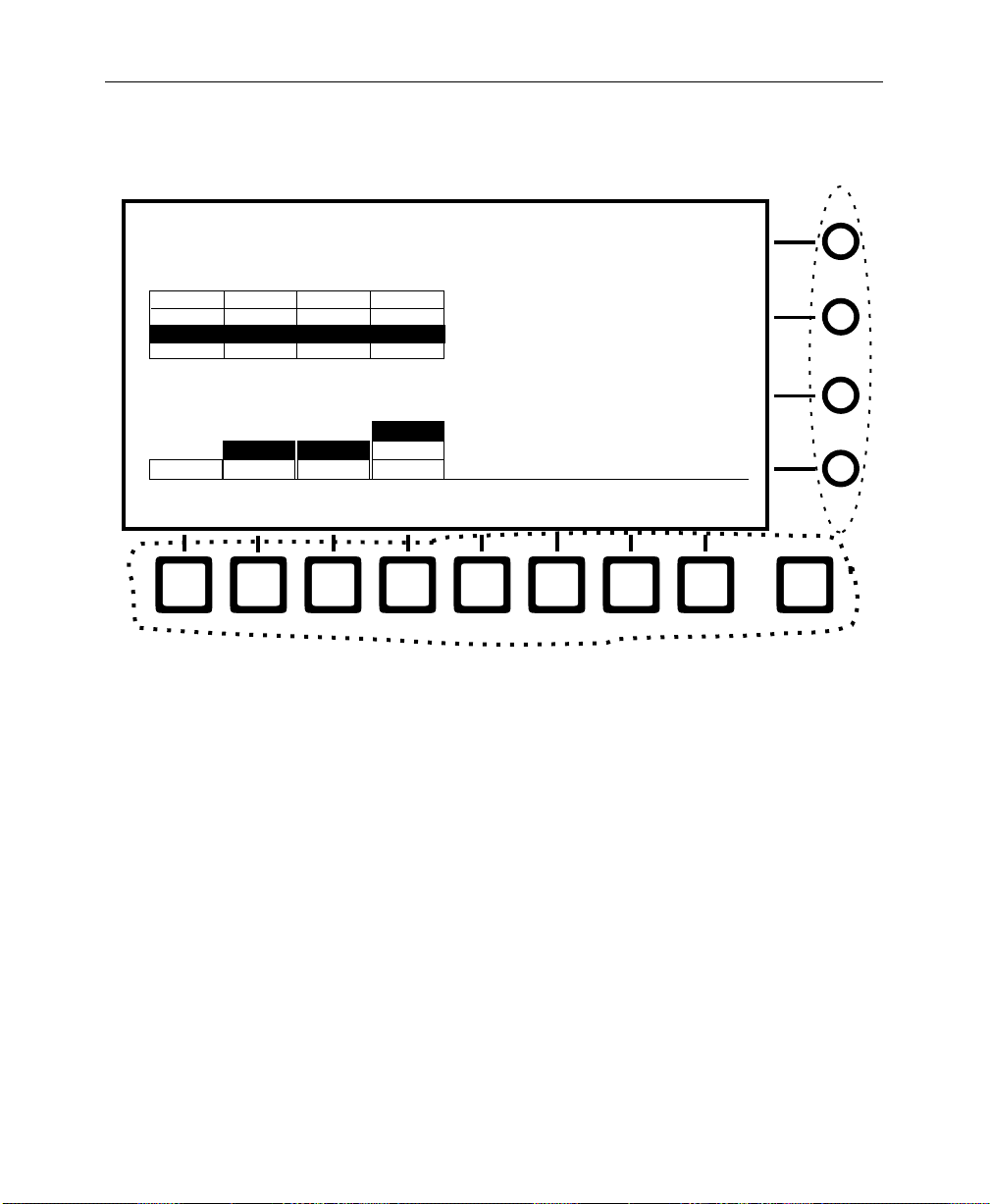
An illustration similar to the following may be used for reference
when you need to access a function via the menu.
NOTE:
The menu illustrations in the rest of this manual do not show
the soft buttons and knobs in order to add clarity to the illustration.
Page 15
Conventions used in this manual
.
Soft Knobs
CHROMA KEY MENU
/chrKey
ME 1 KEY 1
ME 1 KEY 2
ME 2 KEY 1 VARIABLEONON
ME 2 KEY 2
ME 2 KEY 1
CHR KEY
SELECT
ON
ON
ON
ON ON
OFF
FOREGROUND
VIDEO
ON
ON
ON
OFF
BACKGROUND
VIDEO
OFF
FIXED
OFF
VARIABLE
FIXED
OFF
FOREGROUND
CORING
Soft Buttons
Soft Button and Soft Knob References
In the text, soft buttons and soft knobs are shown in
the button or knob label in the display. for example:
SECONDARY
COLOR >
HUE
MODS >
FOREGROUND CORING
SHADOW GAIN
SHADOW CLIP
KEY
ADJUST >
= 7.50 IRE
SETUP>
= 50%
= 50%
EXIT
bold
, using
CHR KEY SELECT
SHADOW GAIN
— soft button
— soft knob
xv
Page 16

Preface
xvi
Page 17

System Overview
1
This section presents a general description of the Grass Valley
Products Model 2200-2 Production Component Digital Switching
Systems.
The Control Panel and Signal Processor descriptions provide a
basic knowledge of the Model 2200 basic architecture.
Basic Architecture
The Model 2200 is a component digital switcher . It can manipulate
CCIR 601 serial component digital and analog component video
and key signals through the use of 10-bit digital processing. An
Analog Chroma Keyer Input Module is also available.
The Model 2200-2 provides two full function mix/effects
subsystems. Up to 32 serial digital inputs which can be mapped to
switcher crosspoint buttons and used as video and/or key
sources. Internal sources are also available, such as Black, Masks,
Color Bars, and Background.
Effects animation functionality may be used to build and run a
sequence of effects. Effects are stored in E-MEM registers as a list
of “keyframes” (see the Operation Reference manual, for a
definition of Keyframes). The E-MEM register operations are used
to learn, recall, copy, and link effect registers.
The layout of the Control Panel is logically structured for efficient
control of video signals.The Menu Display Subpanel allows quick
changes to switcher system parameters.
1-1
Page 18

Section 1 — System Overview
Standard Features
2 Mix/Effects Systems
■
■
Auto-Timed Inputs
Shaped and Unshaped Video Input Conditioning
■
■
Fineline Keying
Key Channel Throughout
■
■
10-Bit Data Processing Throughout
■
Full Complement of Wipe Patterns
E-MEM with Disk Storage
■
■
100 E-MEM registers for Keyframe effects
Multiple-event Keyframes/Effects within a single E-MEM
■
Register
■
User-Preference Programming
1-2
■
Safe Title / Area Generators
■
Extensive Masking
Complex Matte Generators
■
■
Analog Output Program/Preview Capability
Default switcher state —User defined or GVG factory setting
■
■
Chroma Key Auto Setup
Page 19

Optional Features
■
■
■
■
■
■
■
■
■
■
■
■
Optional Features
BORDERLINE® on all Keyers
Dual Chroma Keyers for each M/E
Second Wipe Pattern Generator for each M/E
Kaleidoscope Run Control and Effects Recall1
Two-Channel Effects Send
Three Additional Timed Aux Buses
Key Outputs
Preview Outputs
Tally Outputs
DPM Port
Redundant Power Supplies
Module Extenders
Refer to the end of this section for descriptions of the optional
features.
1. Requires a GVP Kaleidoscope DPM and the Kaleidoscope Interf ace Upg r ade Kit (currently shipped,
to customers who have purchased Kaleidoscope, with the 4.0 Software Release Package, Part No.
074825-07).
1-3
Page 20

Section 1 — System Overview
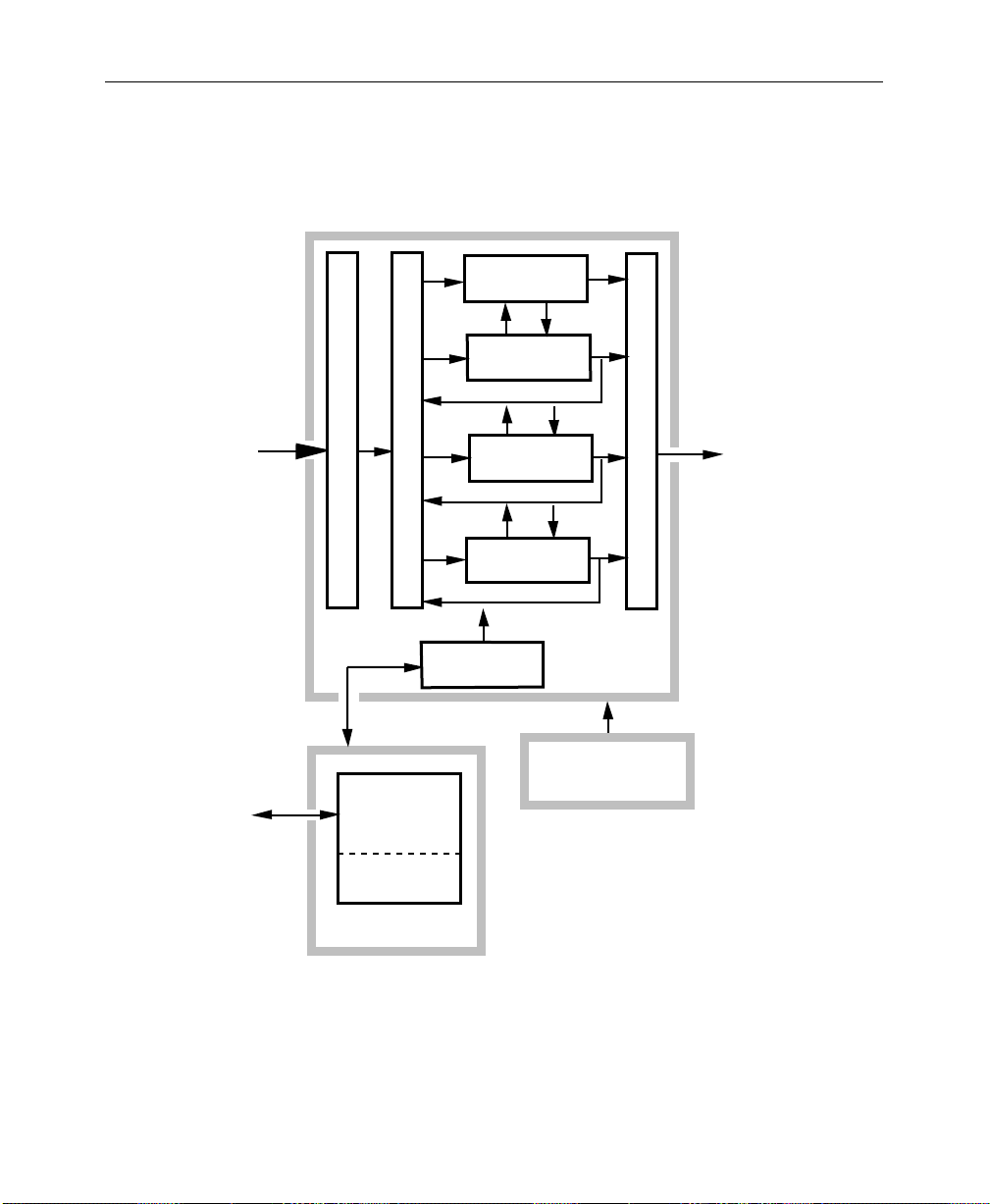
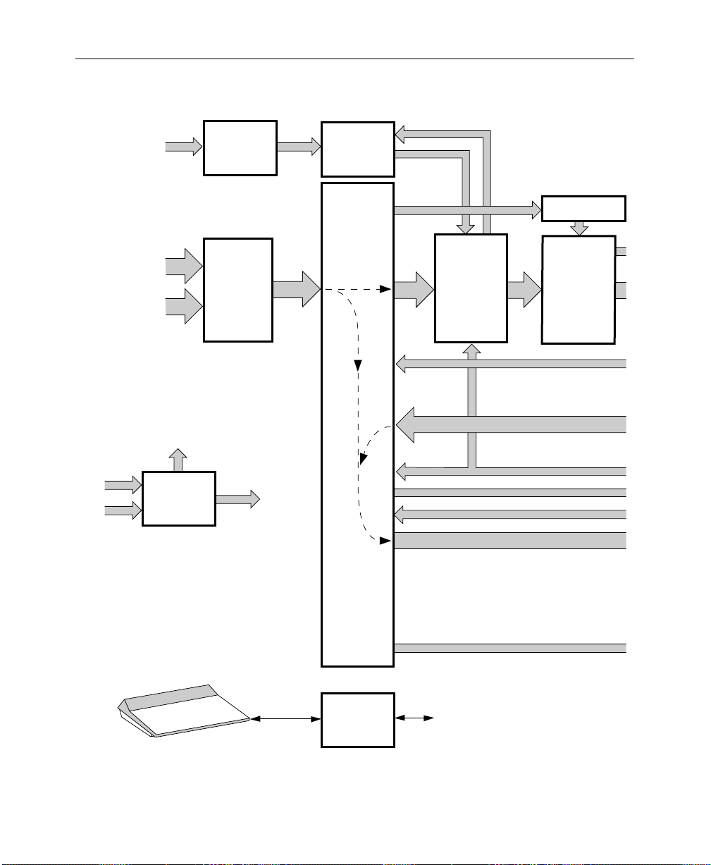
Physical Description
The switcher consists of three main areas: the Control Panel, the
Signal Processor Frame, and the Frame Power Supply (see
Figure 1-1) The electronic circuitry for the Model 2200 is contained
on circuit boards and modules in the Signal Processor Frame and
Control Panel.
Signal Processor Frame
The Signal Processor Frame is a large rack-mounted unit that
houses the system Controller, Mix/Effect logic and processors,
Input/Output interfaces, and Expansion circuit modules.
In addition to the basic system, a typical system may have several
options such as Chroma Keyers, Secondary W ipe Generators, and
Effects Send. Most options are available as circuit boar d modules
(or submodules called “mezzanine” boards) that are installed in
the Signal Processor Frame.
1-4
Refer to the Model 2200
complete description of the Signal Processor.
A main pr ocessor and separate M/E processors reside within the
Signal Processor Frame. Since each M/E has its own processor,
failure of one processor does not disable the entire switcher.
Individual effects can continue to operate independently in a
limited capacity.
Power Supplies
Two power supplies are used in the basic Model 2200 system: a
control panel power supply, located in the control panel tub, and
a 19" rack mount power supply used by the Signal Processor
Frame. Optional Redundant power supplies are available.
Installation and Service
manual for a
Page 21
EFFECTS SEND
MATRIX
MIX EFFECTS
PROCESSOR
Physical Description
TP0625-07
Video/Key
Signals In
Status
Terminal
MIX EFFECTS
PROCESSOR
ANALOG AND SERIAL INPUT MODULES
SERIAL CROSSPOINT MATRIX
MIX EFFECTS
PROCESSOR
CONTROL
PROCESSOR
Signal
Processor
Frame
ANALOG AND SERIALOUTPUT MODULES
Signals Out
Processor Frame
Power Supply
CONTROL
PANEL
LOGIC
CONTROL PANEL
POWER SUPPLY
Control Panel
Figure 1-1. Simplified Block Diagram of the Model 2200
Video/Key
1-5
Page 22
Section 1 — System Overview
Control Panel
The Control Panel is the operator interface for the Model 2200
system. The operator performs all actions via buttons and knobs
and a software-driven menu.
External Interface
Editor
GPI
Enable
Frame Store
Frame Store
Drop
Shadow
Vertical
Opacity Horizontal
Position
Position
Field 2
Field 1
Grab
Freeze
Video
Key
Store
Store
Background
Hue/
Softness
Saturation/
Offset
Enable
Brightness
Pvw
Aux
Key
A
B
VTR3VTR2VTR1Cam3Cam2Cam1Black DPM2DPM
VTR3VTR2VTR1Cam3Cam2Cam1Black DPM2DPM
VTR3VTR2VTR1Cam3Cam2Cam1Black DPM2DPM
VTR3VTR2VTR1Cam3Cam2Cam1Black DPM2DPM
Chroma Keyer
1
1
1
1
Shadow
On
Auto
Setup
Bkgd
Supr
M/E 1
Key 1
R
M
Y
B
G
C
Shadow
Opacity
Chroma Lum
M/E 1
M/E 2
M/E 2
Key 2
Key 1
Key 2
Routr4Routr3Routr2Routr
Routr4Routr3Routr2Routr
Routr4Routr3Routr2Routr
Routr4Routr3Routr2Routr
Periph
Enable
M/E 2
M/E 1
Sec
Sec
Wash
Wash
Matte 2 Flat
Matte
Bk
Bkgd 1
Bkgd 2
1
1
1
1
Selectivity
2
2
2
2
Routr3Routr
Routr3Routr
Routr3Routr
Routr3Routr
Effect Switcher
Picture
Effect
Config
Picture
Panel
Frame
Setup
Effect
Key/
Oper
Stencil
View
Input/
Run
Output
Control
Graphic
Path Aux
Display
Clear
Menu
Color
Shift
Bkgd
Color
Shift
Bkgd
Shift
Color
Bkgd
Shift
Color
Bkgd
Mixer
Config
Keyer
Status
E-MEM Key
Mask Matte
Bus
Disk Misc
M/E 1
Pgm
Key 1
Key 2
M/E
Mode
Chroma
Key
Wipe
Frame
Frame
Store
Aux 1-4 Effects Send Only
M/E 1AM/E 1
M/E 1
M/E 2
Pgm
Transition
Uncal
Bkgd
Uncal
B
On
Uncal
Uncal
Layered
Mix
Cut
Key 1
Effect
Effect Effect
Key
Bkgd
1
A
On
On
Over
Wipe
Auto
Tran
M/E 2AM/E 2
Key 2
Key 1
Key
Key
Priority
2
On
Over
Preset
Black
60
RTD1TK 1GF 2GF 1 GF 2
Transition
Key
A
B
VTR3VTR2VTR1Cam3Cam2Cam1Black DPM2DPM
VTR3VTR2VTR1Cam3Cam2Cam1Black DPM2DPM
VTR3VTR2VTR1Cam3Cam2Cam1Black DPM2DPM
1
1
1
1
1
1
Routr4Routr3Routr2Routr
Routr4Routr3Routr2Routr
Routr4Routr3Routr2Routr
Color
Routr3Routr
Bkgd
2
Color
Routr3Routr
Bkgd
2
Color
Routr3Routr
Bkgd
2
Uncal
Key 1
Shift
M/E 1
Key 2
Uncal
Shift
M/E 1
Uncal
Shift
M/E 1
Uncal
Effect
BkgdABkgd
B
OnOn
Layered
Wipe
Mix
Auto
Cut
Tran
1-6
Page 23
Physical Description
The Control Panel also provides connectors for a status terminal
and the data link to the Signal Processor Frame.
Wipe Mask
Top/Gain
Left Right
Bottom/Clip
Force
Inhibit
Mask
Mask
Box
Sec
Pri
Wipe
Wipe
M/E 1
M/E 1
M/E 2
Key 1
Key 2
Exit
Preview Only
M/E 2
M/E 1
Key 2
Pvw
Effect
Effect
Key
Key
Key
Priority
2
1
On
On
Over
Over
Preset
Black
60
M/E 2
Pvw
Keyer
Normal Border
Key
Over
Video
Fill
Linear
Key
Key
On
Keyer
Normal Border
Key
Over
Video
Fill
Linear
Key
Key
On
Inhibit
Mask
Matte
Fill
Lum
Key
BkgdBBkgd
Inhibit
Mask
Matte
Fill
Lum
Key
BkgdBBkgd
Shadow
Force
Mask
Split
Key
Chroma
Key
A
Shadow
Force
Mask
Split
Key
Chroma
Key
A
Bus Delegate
Pvw
Invert
Video
Key
Pri
Preset
Pattern
Key
1
Invert
Video
Key
Pri
Preset
Pattern
Key
1
Mask Aux1Aux2Aux
OutlineExtrude
Borderline
Size/Position
Show
Key
Borderline
Auto
Select
Opacity
Key
Sec
Preset
Pattern
Gain
Key
2
Clip
OutlineExtrude
Borderline
Size/Position
Show
Key
Auto
Borderline
Select
Opacity
Key
Sec
Preset
Pattern
Gain
Key
2
Clip
3
Matte
Hue/
Softness
Saturation/
Offset
Brightness
Hue/
Softness
Saturation/
Offset
Brightness
Key 1
Aux
Aux
5
4
Matte
Pri
Sec
Wipe
Wipe
Wash
Wash
Matte 2
Flat
Matte
K1 Fill
K1 Border
K2 Fill
K2 Border
Sec Wipe
Pri Wipe
Matte
Select
Pri
Sec
Wipe
Wipe
Wash
Wash
Matte 2
Flat
Matte
K1 Fill
K1 Border
K2 Fill
K2 Border
Sec Wipe
Pri Wipe
Matte
Select
Symmetry
Opacity
Mask
Preset Size Aspect
Invert
Mask
Bus
M/E 2
Key 2
Pattern Mix
Stop
Next
KF
Hold
Input
Reverse
Rewind
Run
Run Control
E-MEM
Auto
Recall
Chan 1
Enable
All
Chan 2
Misc
Bkgd
Global
Camera
Enables Edit
Softness
Width
Near
Side
Auto
Run
M/E 1
M/E 2
Soft
Border
Aspect
Rotate
Rotate
Speed
Pos
Rotation TypeRotate
Pattern
Mix
Far
Side
1345804-42224438
Lock
Learn
Seq
Effect
Dis
Bank
Rotate
Normal
Mag
Wipe Direction
M/E 1
Pri
Freeze
Video
Source
Target
Locate
3D
Locate
Axis
Skew
Persp
XY
8
7
56
4
123
Undo
0
.
Reverse
Flip
Flop
M/E 1
M/E 2
M/E 2
Sec
Pri
Sec
Delegate
Freeze
Key
Camera
World
Rotate
Size/
Locate
Spin
Aspect
Post
Xform
Center
Z
+/ ---
9
Bank 0
Bank 1
Trim
Tran
Rate
Enter
User 1
User 3
User 5 User 6
RandomMenu Texture User
Wipe
Undo
Pos
V
H
Split
Pattern Modifiers Positioner
Axis
Lock
Knob
Control
Multi
M/E 1
Pri
Clear
Work
Buffer
Cut
Copy
Paste
Mark
Multi
Model
Chan 2
M/E 1
Sec
Const
Dur
Get
Put
Time
Cursor
Mark
Block
Norm
2200
M/E 2
Pri
Prev Next
Go To
KF
Mark
Cursor
Modify
User 2
User 4
Learn
User
Wipe
Pos
Auto
CameraGlobalChan 1
M/E 2
Sec
Go To
Time
Effect
DurKFDur
Insert
Before
Insert
After
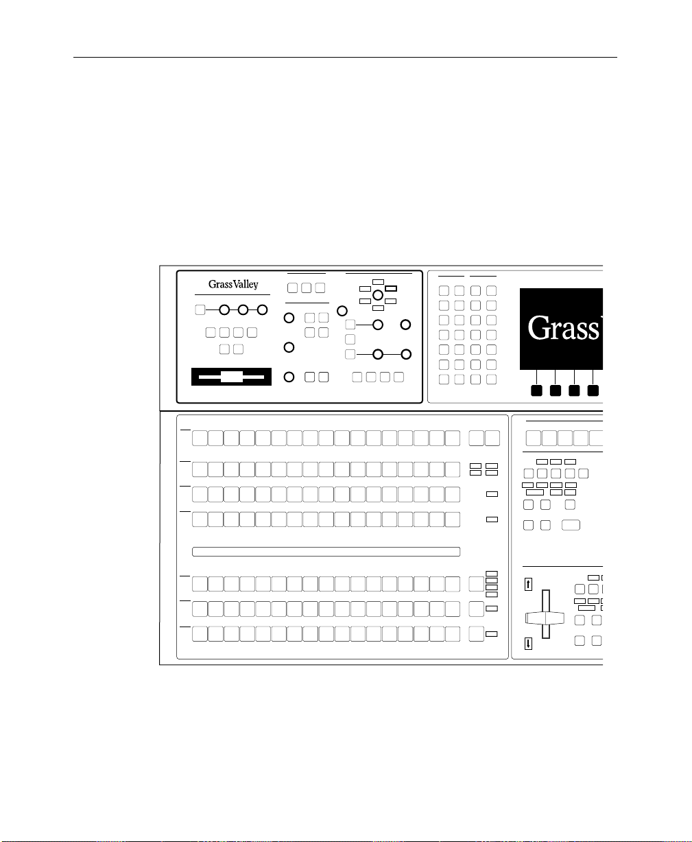
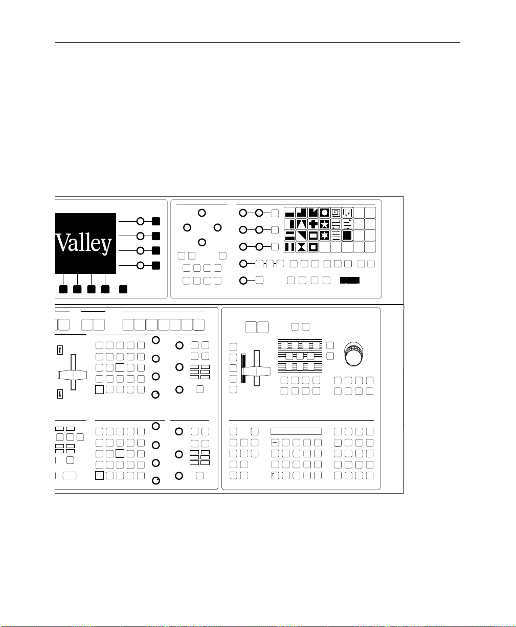
Figure 1-2. Model 2200-2 Control Panel
1-7
Page 24

Section 1 — System Overview
Video and Key Inputs and Outputs
Inputs
Two types of input modules may be installed in the Signal
Processor Frame to suit the needs of your installation. The
following types of input modules are available.
NOTE:
Each of the serial or analog inputs can be treated by the switcher
as either a video input or a key input.
Serial Digital Input Module – provides 8 inputs, auto-timed
■
within a range of ±18 microseconds. Two modules are
supplied in the standard configuration. Two modules are
available as options. With four modules installed ther e ar e 32
inputs available.The modules are located in Bay C.
■
Chroma Key Input Modules (optional) – Either one or two
Chroma Key Input Modules may be configured. These
modules allow full bandwidth chroma keys. Each module has
two inputs. Each input has three BNC connectors labeled:
G/V, B/U, and R/V. There is a separate gain adjustment near
each BNC connector. The format for each input is userselectable from RGB, YUV, Beta or MII. The module is located
in Bay C.
Refer to the
Model 2200 Installation and Service
manual, Section 3,
Functional Description, for more information.
Refer to the
Model 2200 User Guide
for information on assigning
input formats and adjusting the timing.
1-8
Page 25

Physical Description
Outputs
Output modules are placed in the rear bay of the Signal Processing
Frame. The following module types are available:
■
Serial Output Modules (2 standard, each adding 8 outputs
with two BNCs)
Analog Output Module (1 optional with RGB/Y, CR, CB and
■
Key outputs)
The standard Digital Output Modules have the following outputs:
■
Mask Bus
Switched Preview Video
■
■
M/E 1 and M/E 2 Program Video and Key
M/E 1 Key1 or M/E 1 Clean Feed
■
■
M/E 2 Key or M/E 2 Clean Feed
■
Aux Buses 1A through 2B
2
■
Framestore Video and Key
The optional Analog Output Module has the following outputs:
■
M/E 2 Program Out
M/E 2 Preview Out
■
1. No Lookahead Preview Option installed.
2. Lookahead Preview Option installed.
1-9
Page 26

Section 1 — System Overview
Functional Description
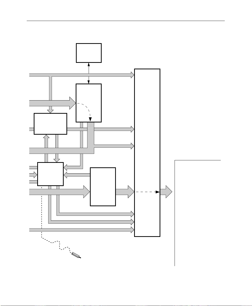
General Overview
Figure 1-3 shows a simple video flow diagram for the Model 2200.
Video and key signals enter the input modules of the Model 2200,
which consist of component analog and/or component serial
digital formats. The analog signals are converted to digital format,
and all inputs are timed and conditioned.
The digital signals are then passed to the V ideo and Effects Section
where keying and mixing take place. This section also provides
effect modifications, such as wipes and keyframing, that can be
applied to selected inputs.
In the Output Section, digital video and key signals are routed to
the Serial Digital Output Modules and the optional Analog
Output Module before leaving the Signal Processor.
1-10
Video Processing
Input video and key signal selections are made by the Crosspoint
Matrix under control of the system Controller, according to
operator assignments entered via the Control Panel.
In addition to primary (external) video, secondary (internal)
sources such as Masks, M/E re-entry video, and optional Effects
Send are available as inputs to the crosspoint matrix.
Any suitable component digital signal from the Crosspoint matrix
may feed the Chromatte™ Chroma Keyer Module option. Analog
Component signals may also be used as Chroma Key sources.
Keyers in each Mix/Effects bank provide outputs to the Mixer
Interface crosspoints. These outputs may be sent outside the
switcher for external processing, or may be routed to the M/E
mixers and wipe generators. The Effects Send outputs can be
directed to the Framestore option for image capture.
Page 27

Functional Description
Each M/E has two keyers and two background buses (A and B) as
inputs. In standard mode, Keyers 1 and 2 can be mixed into a
composite video and key which can be forwarded to the output,
or M/E 1 can be reentered into M/E 2. In layered mode,
Background Buses A and B are also used as keyers.
Preview capability allows monitoring of sources at many points in
the signal flow. You can preview video from the M/E mixers,
switched preview bus, or mask bus.
Eight GPI inputs are provided. You can assign each of the GPI
inputs via the GPI Input Menu to perform a specific function
when triggered.
The editor interface consists of an asynchronous RS-422, 38.4K
baud serial communications port, managed by a communications
processor. Refer to the Model 2200/3000/4000
manual for information on software functions and protocols
observed by the editor port.
Serial Protocols
1-11
Page 28
Section 1 — System Overview
e
y)
e
a
Component
Analog
Chroma Key
Inputs
Video Signals
In
Key Signals
In
e
ital
ce
Clocks
to all
modules
SYNC
GENERATOR
DUAL
CHROMA KEY
INPUT
MODULES
SERIAL
DIGITAL
INPUT
MODULES
ANALOG
INPUT
MODULES
modules
Timing
Signals
to all
video
DUAL
CHROMA
KEYER
80 X 48
VIDEO
CROSSPOINT
MATRIX
M/E1
& M/E2
Chr. Key
Aux Bus
1A-4B
EFFECTS SEND
MODULES
M/E
Video
and
Key
QUAD
KEYER
MODULES –
M/E 1
& M/E 2
MIXER
MODULE
CROSSPOINTS
Frame Store Video and Ke
M/E Program Video and K
Clipped Mask and
Mask Store Video
Switched Preview and Mask
Black, Background 1 and 2, and Test Sign
Program, Preset, and DSK Video and K
CONTROL PANEL
1-12
CONTROLLER
(control buses not
shown for clarit
Aux Bus 5A-9B Video and Key
To/From
All Circuits
Page 29
SECONDARY
0622
104R
e
WIPE
OPTION
Functional Description
Aux Bus 1A-4B
Video and Key
FRAME STORE
FOR VIDEO, KEY,
AND MASK
STORAGE
Mask
Store
Input
Mask
Store
Output
M/E Pvw
Video
PREVIEW
Switched Preview
M/E and DSK Preview
Figure 1-3. V ideo
DSK Pvw
Video
Mask and
DIAGNOSTIC
PROBE
M/E 1
& M/E 2
MIXERS
Frame Store
Video
and Key
M/E 1 and M/E 2
Program Video
and Key
Program
PGM/PST
MIXER
AND
DUAL DSK
Video
& Key
& Clean
Feed
Video
NOTE:
Primary Video Paths are
Indicated by Wide Arrows
SERIAL
DIGITAL
AND
ANALOG
OUTPUT
MODULES
Outputs (Standard and Option
Frame Store Video and K
M/E 1 and M/E 2
Program Video and Key
Program Video and Key
Clean Feed Video
DSK Preview Video
Mask
Switched Preview
M/E1 and M/E 2
Preview
DSK Preview
Aux Bus Video and Key
-
1-13
Page 30

Section 1 — System Overview
Description of Options
The following options are currently available for the Model 2200
switcher. For more details on these options, refer to the
appropriate subpanel descriptions later in this manual.
Chromatte Advanced Chroma Keyer
Each foreground keyer in M/E 1 and M/E 2 has access to an
optional component chroma keyer. Either an internal component
digital signal or an external component analog signal from one of
the Chroma Key Input Modules can be used as the chroma key
source. Color background suppression, foreground suppression
and shadow processing are included as features.
BORDERLINE Key Edge Generation
BORDERLINE® Key Edge Generators are available for each keyer
in the switcher. The Borderline feature is implemented as a
submodule that plugs onto the Keyer module of any M/E.
1-14
Each Borderline generator supports 1, 2, or 3 line wide borders for
border and outline modes and 1 to 6 line wide edges for shadow
and extrude modes. Fill within the key edges may be either video
or matte.
Secondary Wipe Generator
A Secondary W ipe Generator option provides a second pattern for
each M/E. The Secondary Wipe Generator Submodules mount on
the M/E 1 and M/E 2 Mix/Wipe Modules.
Page 31

Effects Send
Effects Send provides a method of integrating digital effects
devices into the switcher mix/effects system. Up to two send
channels can be used to route the video and key from an M/E to
and from an external digital effects system.
Look Ahead Preview
Look ahead preview processing is provided for both M/Es with
this option. Submodules mount on the M/E 1 and M/E 2
Mix/Wipe Modules.
Tally Relay Frame
The Tally Relay Frame provides external tally outputs that reflect
the switcher status. A rear-panel interconnect board provides the
relay contacts on two connectors for on-air T ally A and on-air Tally
B. The frame can hold up to three Tally Modules. Pinouts for the
Tally connectors are given in the Installation section of the Model
2200 Installation and Service manual.
Description of Options
1-15
Page 32

Section 1 — System Overview
Remote Aux Bus
The Remote Aux Control Panel Option allows you to control the
Model 2200’s aux buses from a remote location. As many as 32
Remote Aux Panels can be daisy-chained to the switcher. There
are three Remote Aux Panel configurations available, identified by
the number of rack units (RUs) each occupies in the equipment
rack.
The panels are designed to control 32 external inputs (16 unshifted
and 16 shifted).
Timed Aux Output
The Timed Aux Output Module provides four independent
output pairs (video/key) from aux buses 5A through 8B for use
with Kaleidoscope and DPM systems.
1-16
Page 33

Powering Up
2
Startup and Configuration
This section describes turning on the system, setting up user
preferences, and setting up system parameters.
The Model 2200 is designed for continuous operation. Use the
following procedures to power-up the switcher when it has been
turned off.
1. Turn the power switch on the front of the Signal Processor
Power Supply to the ON position. Verify that the power
supply voltage LEDs on the front of the Power Supply are lit
and that the fans in the Processor are on.
2. Raise the Control Panel and turn the power supply switch to
the ON position. Verify that the green RUN LED on the CPU
Board (located in the middle of the tub) is lit.
3. Verify that the Model 2200 sign-on logo is displayed on the
Menu Display.
4. Verify that the panel pushbutton lamps are on and that the
E-MEM and Transition subpanel readout LEDs are on.
If any of the above conditions are not present, turn the system
power off and refer to the Diagnostics and Troubleshooting
section in the Installation and Service manual.
2-1
Page 34

Section 2— Startup and Configuration
Booting-Up
When the system is turned on, the switcher will initialize into a
defined default state. This default state may be either a userdefined default or a GVG factory default of switcher enabled
levels, as selected in the Define Defaults Menu (see Section 3,
Model 2200 Operation Reference manual).
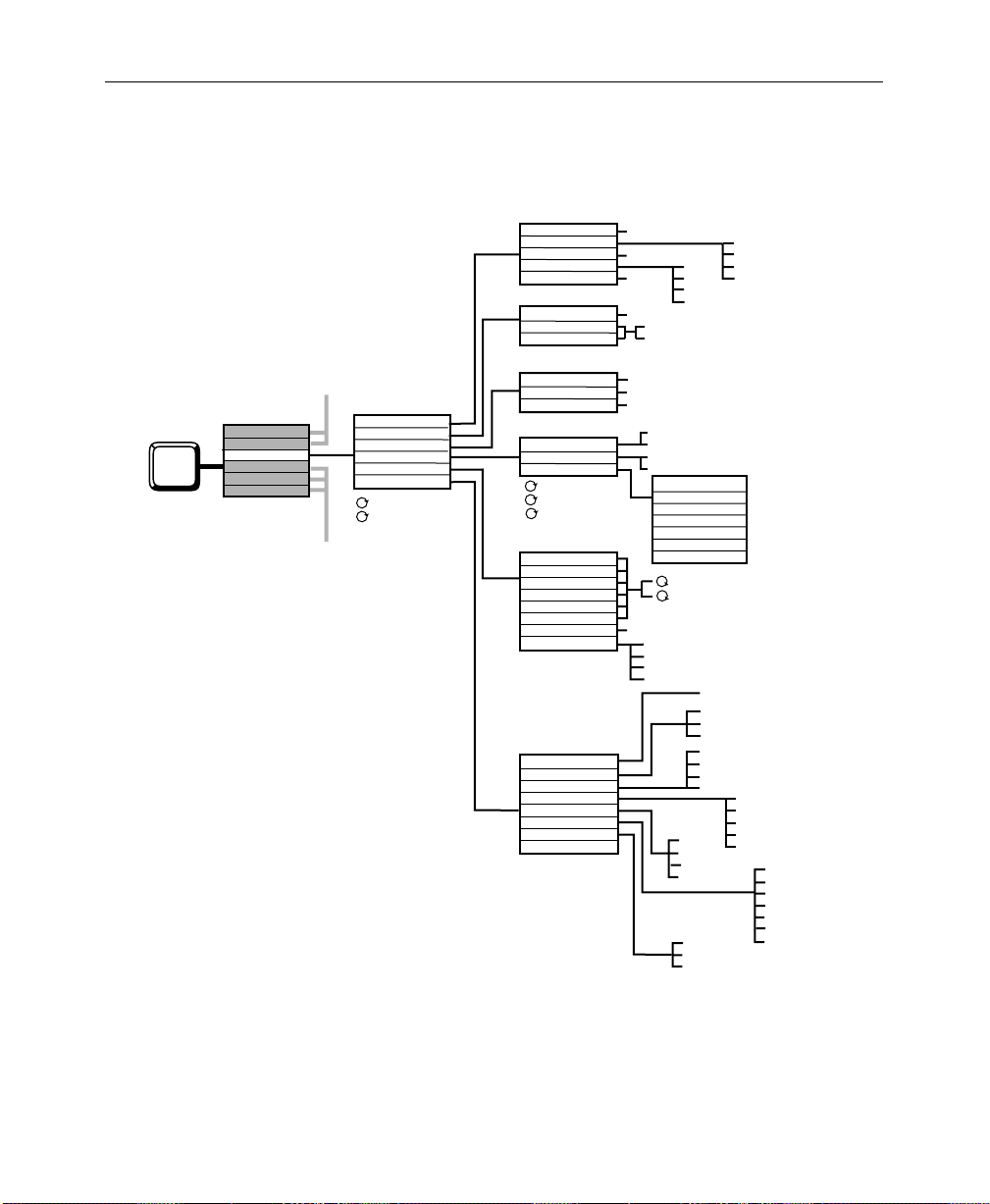
Software Setup
The system parameters to be used at your site are usually
configured following installation of the equipment. Use the
following procedures to configure the 2200 system to your
installation. In addition to assigning sources, the process includes
setting configuring inputs, output levels, external interfaces, and
system parameters. These functions are accessed via the Control
Panel Configuration Menu sub-menus (see Figure 2-1., Parts 1
through 3).
2-2
The Configuration Menu
The Configuration Menu is a top-level menu which provides
access to the User Preferences, System Parameters, Inputs,
Outputs, External Interface, and Aux Bus Formats sub-menus.
Page 35

CONFIGURATION MENU
/config
Software Setup
USER
PREFS > INPUTS >
SYSTEM
PARAM >
T o begin the setup pr ocess, press the CONFG button on the Menu
Display Subpanel to display the Configuration Menu and the submenu choices.
1. USER PREFS > — Set up operating parameters, such as Keyer
and Preview preferences and default switcher states.
2. SYSTEM PARAMS > — Set aspect ratio, the matte generator limiter
and the system clock.
3. INPUTS > — Define your inputs and name crosspoint buttons.
4. OUTPUTS > — Adjust the luminance and chroma limiter
settings on the switcher outputs.
5. EXTERN I/F > — Select or change settings for the Editor, DPM,
and Peripherals Interfaces connected to the Model 2200.
6. AUX BUS FORMAT > —Sets the “B” Aux Bus on Aux buses 5B–9B
to be either a separate video or key bus to accompany the
corresponding “A” Aux Bus. Set Aux Buses 1 through 4
(physical/logical) for shaped or unshaped video output.
OUTPUTS >
EXTERN
I/F >
AUX BUS
FORMATS>
2-3
Page 36

Section 2— Startup and Configuration
Configuration Sub-Menus
USER PREFERENCES
■ Keyer Prefs
■ Preview Prefs
■ Beeper Prefs
■ Define Defaults
■ E-MEM Prefs
SYSTEM PARAMETERS
■ Aspect Ratio
■ Matte Gen Lim
■ Set Clock Menus (Date /Time)
2-4
INPUTS MENUS
■ Analog Video Inputs
■ Analog Key Inputs
■ Analog Input Timing
■ Map Inputs and Name Crosspoint Button
■ Chroma Key Inputs
■ GPI Inputs
OUTPUTS MENU
■ Output Digital Resolution Menu
Page 37

EXTERNAL INTERFACE MENUS
■ Editor I/F
■ DPM I/F
■ Peripheral I/F
■ GPI Outputs
AUX BUS FORMAT MENU
■ Aux Bus Shaping
Software Setup
2-5
Page 38

Section 2— Startup and Configuration
SHIFT MODE
KEYER PREFS
PREVIEW PREFS
BEEPER PREFS
E-MEM PREFS
DEFINE DEFAULTS
USER PREFS
SYSTEM PARAM
CONFG
(Part 1)
INPUTS
OUTPUTS
EXTERN I/F
AUX BUS FORMAT
LATCH
NORMAL
DSK DROP
KEY MEMORY
CLEAR KEY MEM
PVW SELECT
PVW MODE
DIM PVW
PUSH TO PVW
BEEPER ON/OFF
WARNING
END OF KNOB
KNOB CENTER
INACTIVE KNOB
RUN LEVER
KEYFRAME EDITING
MASTER E-MEM
M/E SELECT
GVG DEFAULT
SET DEFAULT
ON
OFF
ON
OFF
SECTION SELECT
BUS SELECT
M/E 1
M/E 2
PGM PST
ON
OFF
ON/OFF
ON/OFF
ON/OFF
ON/OFF
ON/OFF
ENABLE/DISABLE
ENABLE/DISABLE
300 STYLE/NORMAL (3 M/E only)
M/E 1
M/E 2
M/E 3
AUTO
LOOKAHEAD
PGM
PUSH TO PVW
TIMEOUT
CLEAR XPT
CLEAR BUS
CLEAR SECT
CLEAR SWCHR
ALL KEYERS
DELEG KEYER
OFF
0764-00 (PT 1)
2-6
Software Version 5.3
ASPECT RATIO
FIELD DOMINANCE
SET CLOCK
MATTE GEN LIM
See CONFG Part 2
See CONFG Part 3
4 X 3
16 X 9
SELECT
CONFIRM
XMITABLE
VALID RGB
BOTH
NONE
FIELD 1
FIELD 2
NONE
DATE — YEAR MONTH DAY
TIME — HOUR MINUTE SECOND
† NOTE: Some soft knob adjustments have been omitted for clarity.
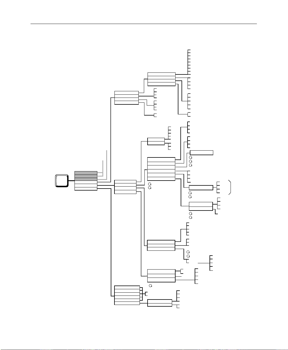
Figure 2-1. Configuration Menu Tree (Part 1 of 3)
Page 39
Software Setup
USER PREFS
SYSTEM PARAM
CONFG
(Part 2)
INPUTS
OUTPUTS
EXTERN I/F
AUX BUS FORMAT
Software Version 5.3
CARD SELECT
INP n FORMAT
INP n SETUP
INP n FORMAT
INP n SETUP
CARD SELECT
INP n SETUP
INP n SETUP
See CONFG Part 1
See CONFG Part 3
ANLG VIDEO INPUTS
ANLG KEY INPUTS
ANLG INPUT TIMING
MAP INPUTS
CHR KEY INPUTS
GPI INPUTS
TOP TEST SIGNAL
BOTTOM TEST SIGNAL
CARD SELECT
INP n TIMING
INP n TIMING
VIDEO/KEY FORMAT
LOG PHYS INPUTS
NAME XPT BUTTON
VIDEO INPUT
KEY INPUT
CHROMA KEY INPUT
INPUT 1
INPUT 2
INPUT 3
INPUT 4
INPUT 5
INPUT 6
SETUP
INPUT FORMAT
GPI SELECT
MISC
KF EFFECT
AUTO TRANS
CUT
E-MEM
FRAME STORE
PROGRAM GPI
† NOTE: Some soft knob adjustments have been omitted for clarity.
CARDS 1– 8 (INPUTS 33–64)
ON/OFF
RGB
BETA
ON/OFF
YUV
MII
CARDS 1– 8 (INPUTS 33–64)
NO SETUP
KEY SETUP
CARDS 1– 8 (INPUTS 33–64)
1–4
1–4
UNSHAPED VIDEO
SHAPED VIDEO
LOG CHANNEL
PHYS INPUTS
CURSOR BACK
ACCEPT CHAR
CURSOR FORWRD
DELETE CHAR
SAVE STRING
GET STRING
ACCEPT NAME
COARSE TIMING
FINE TIMING
ON/OFF
RGB
BETA
YUV
MII
GPI 1 through GPI 8
AUX TALLY
LOG CHAN TALLY
DISABLE GPI
RUN
REWIND
AUTO RUN
REVERSE
M/E1
M/E2
M/E3
PGM PST
VIDEO GRAB
KEY GRAB
MASK GRAB
RGB
BETA
YUV
MII
M/E1
M/E2
M/E3
PGM PST
PGM PST PST BLACK
0764-00(PT 2)
RECALL M/E1
RECALL M/E2
RECALL M/E3
RECALL MASTER
AUTO RCL
EFF DISSSOLV
SEQUENCE
Figure 2-2. Configuration Menu Tree (Part 2 of 3)
2-7
Page 40
Section 2— Startup and Configuration
DIGITAL RES
OUTPUT SELECT
LUM LIMITER
CHROMA LIMITER
See CONFG Part 2
See CONFG Part 1
USER PREFS
SYSTEM PARAM
CONFG
(Part 3)
Software Version 5.3
INPUTS
OUTPUTS
EXTERN I/F
AUX BUS FORMAT
EDITOR I/F
DPM I/F
PERIPHERAL I/F
GPI OUTPUTS
AUX 5B
AUX 6B
AUX 7B
AUX 8B
AUX 9B
AUX BUS SHAPING
Figure 2-3. Configuration Menu Tree (Part 3 of 3)
OUTPUT SELECT
RESOLUTION/DITHER
OUTPUT SELECT
RESOLUTION/DITHER
PGM
ME1 PGM
ME2 PGM
ME3 PGM
PEAK WHITE
PEAK BLACK
BOTH
OFF
PEAK
OFF
BAUD
PARITY
DEVICE SELECT
DPM TYPE
K'SCOPE SOURCES
CHANNEL ROUTING
DPM MAP AUX BUS
DPM MAP INPUTS
EFF SEND DELAY
CONTROL DELAY
BAUD
PARITY
PERIPH TRIGGER
PGM CUT TRIGGER
SELECT GPI
E-MEM LEVEL
GPI LENGTH
VIDEO
KEY
PHYS AUX SELECT
UNSHAPER
2400
4800
9600
19200
38400
ODD
EVEN
NONE
GPI 1-8
AUX 1
AUX 2
AUX 3
AUX 4
ON
OFF
OFF
GPI 1-8
M/E 1 PGM
M/E 2 PGM
M/E 3 PGM
DSK PGM
DSK CLEAN
AUX 1
AUX 2
AUX 3
AUX 4
10 BIT/ON
10 BIT/OFF
8 BIT/ON
8 BIT/OFF
M/E 1 PVW
M/E 2 PVW
M/E 3 PVW
DSK PVW
DSK DIRTY
10 BIT/OFF
8 BIT/ON
DPM 1
DPM 2
DPM 3
DPM 4
KSCOPE
KRYSTAL
OTHER FIXED
NONE
SET DEFAULTS
SWTCHR XPT BUTTON SELECT
K'SCOPE BUTTON
SWITCHER BUTTON.
SWR IN
SWR OUT
BOTH
OFF
DEVICE SELECT
NO. OF CHANNELS
CHAN 1 = AUX ...
DPM SELECT
CHANNEL SELECT
VIDEO INPUT
KEY INPUT
2400
4800
9600
19200
38400
ODD
EVEN
NONE
TRIGGER SELECT (A THRU H)
DEVICE NO.
FUNCTION NO.
LEVEL ASSIGN
FIRE
MISC
DPM 1
DPM 2
DPM 3
DPM 4
MISC
DPM 1
DPM 2
DPM 3
DPM 4
0764-00(PT 3)
DPM 1
DPM 2
CHAN A-H
AUX 1-9
DPM 3
DPM 4
DPM 1
DPM 2
DPM 3
DPM 4
A, B, C, D, E, F, G, H
2-8
Page 41
Setting User Preferences
Use the User Preferences Menus to gain access to keyer, preview,
and switcher defaults submenus.
1. From the Configuration Menu, press the USER PREFS > button
to access the User Preferences Menu.
ANALOG INPUT TIMING MENU
/config/inputs/anlg_inp_timing
INPUTS
CARD 1
CARD 2
CARD 3
CARD 4
CARD 5
CARD 6
CARD 7
CARD 8
CARD 2
CARD
SELECT
33-36
C0 4
37-40
41-44
45-48
49-52
53-56
57-60
61-64
1
1
1
1
1
1
1
1
1
2
3
4
INP 37-38
TIMING
1
1
1
1
1
1
1
1
1
2
3
4
INP 39-40
TIMING
Software Setup
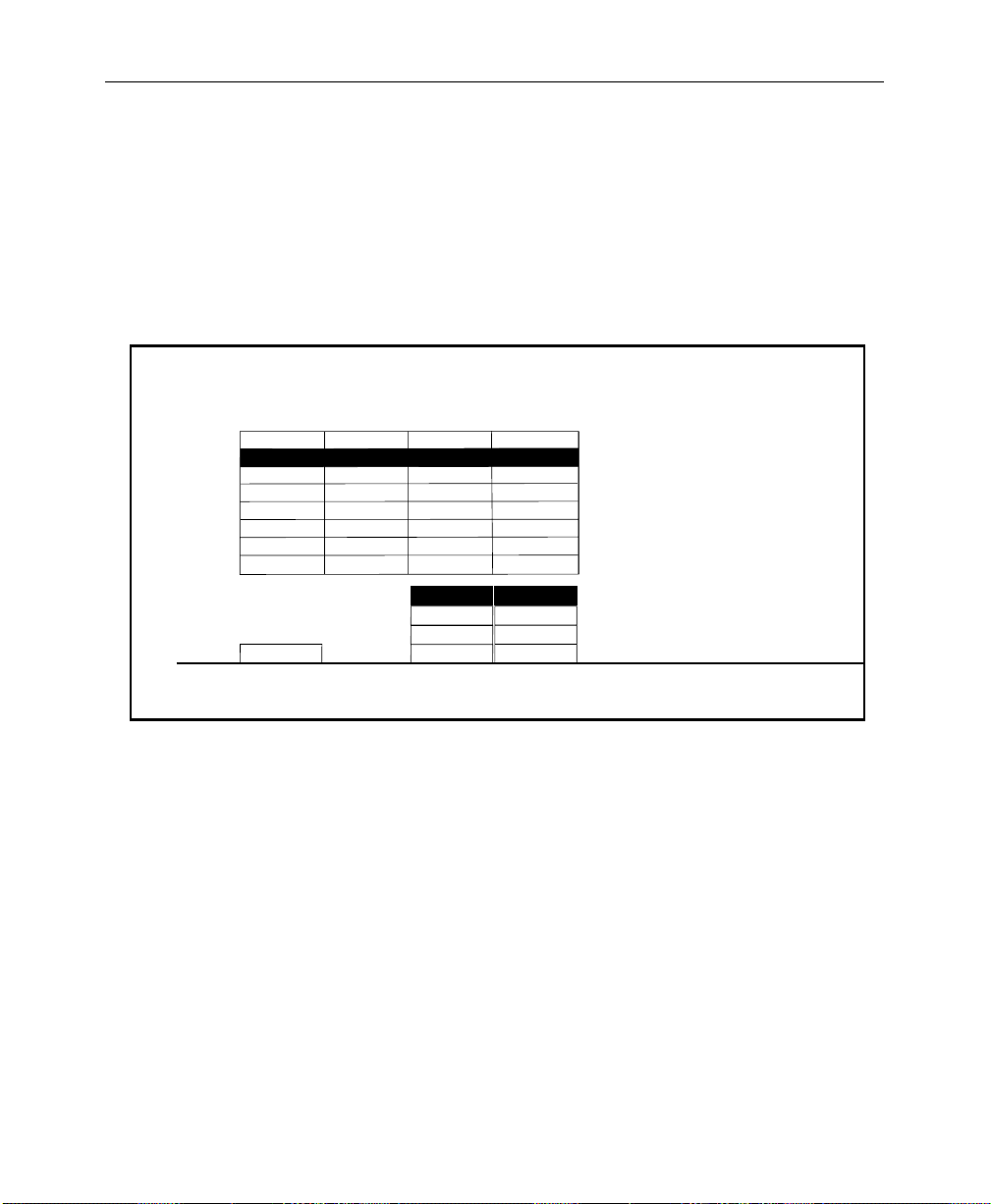
2. Select either LATCH or NORMAL with the SHIFT MODE soft button.
The LATCH selection allows you to lock any switcher
crosspoint bus into a shifted (UPPERCASE) state. This
allows ready access to those input sources mapped to
shifted crosspoints. (See “Configuring Switcher Inputs”
on page 2-24.)
With LATCH enabled on the User Preferences Menu, press
and hold the SHIFT button while selecting a crosspoint.
The bus containing that crosspoint is now locked into a
shifted state. Any crosspoint selected on this bus will now
2-9
Page 42

Section 2— Startup and Configuration
be a shifted crosspoint. The SHIFT button light will remain
ON while the bus is in this state.
T o unshift a bus, pr ess and hold the SHIFT button. Select a
crosspoint button. The bus is now unshifted, and the
SHIFT button lamp is OFF.
3. Select the KEYER PREFS > submenu.
Setting Keyer Preferences
From the User Preferences Menu, pr ess the KEYER PREFS> button to
display the Keyer Preferences Menu:
KEYER PREFS MENU
config/user prefs/keyer prefs
2-10
DSK
DROP
ONON
OFFOFF
KEY
MEMORY
CLEAR KEY
MEM>
1. The DSK DROP button allows you to enable or disable DSK
Drop mode. DSK Drop mode ON drops any DSK when a
program bus crosspoint is pressed. (This is usually left OFF.)
2. The KEY MEMORY Button allows you to turn on or off the key
memory feature. ON enables crosspoints to remember all key
settings. (This is usually left ON.)
Page 43
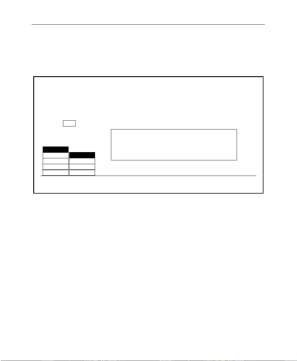
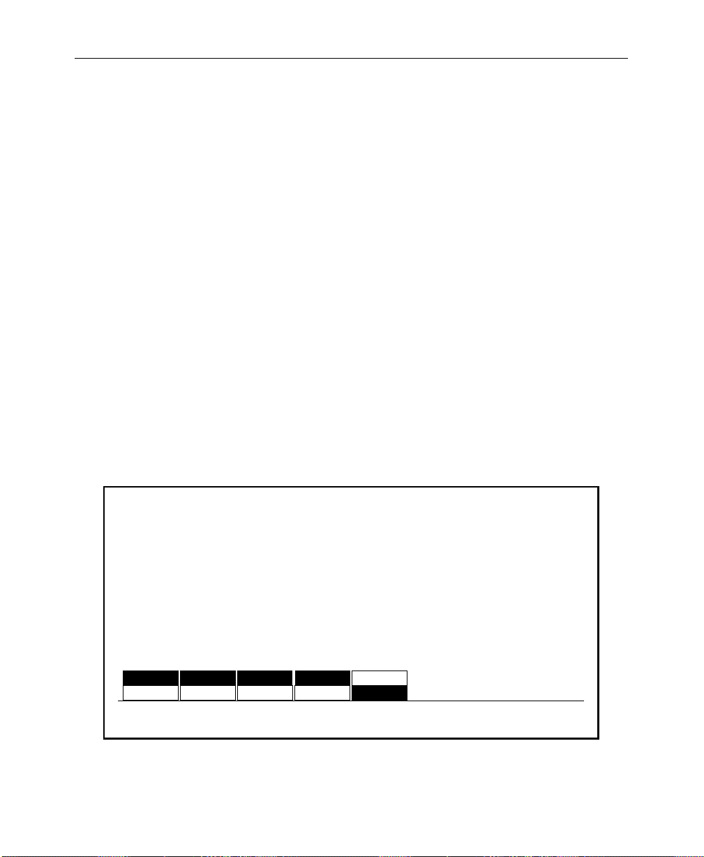
3. Press CLEAR KEY MEMORY to invoke the Clear Key Memory
Menu.
CLEAR KEY MEMORY MENU
config / user prefs / keyer prefs / clear key mem
CURRENT
XPT
7
Press a button below to clear key memory for –
CLEAR XPT: the current xpt on the selected bus
M/E 1
M/E 2
DSK
AUX
MASK
SECTION
SELECT
A
A
B
KEY 1
KEY 2
BUS
SELECT
CLEAR BUS: all xpts on the selected bus
CLEAR SECTION: all xpts on all buses in the selected section
CLEAR SWITCHER: all xpts in the switcher
CLEAR
XPT
CLEAR
BUS
CLEAR
SECTION
CLEAR
SWITCHER
Software Setup
This menu allows you to clear the key memory settings for
various areas of the switcher.
4. W ith the SECTION SELECT and BUS SELECT buttons, select the area
of the switcher whose key memory you wish to clear.
To select a specific crosspoint on a bus: After selecting the
section and bus, press the specific crosspoint on the selected
bus. (The number of that crosspoint will appear in the
CURRENT XPT box in the menu.)
5. Use the CLEAR XPT, CLEAR BUS, CLEAR SECTION, or CLEAR SWITCHER
button to clear the desired memory area.
6. Press EXIT to return to the User Preferences Menu.
2-11
Page 44

Section 2— Startup and Configuration
Setting Preview Preferences
From the User Preferences Menu, pr ess the PREVIEW PREFS> button
to display the Preview Preferences Menu.
NOTE:
It is important to note that these menu setups affect only the
PVW output connectors and the PVW Monitor(s).
PREVIEW PREFS MENU
config/user prefs/preview prefs
M/E 1
PGM/PST
PVW
SELECT
PGM
LOOKAHEAD
PGM
AUTO
LOOKAHEAD ON
PGMM/E 2
PVW
MODE
ALL KEYERS
OFFM/E 2
OFF
ALL KEYERS
DELEG KEYER
OFF
DIM
PVW
1. Use the PVW SELECT button to select the switcher subsystem;
M/E 1, M/E 2, or PGM PST, that you wish to set preview
options for.
OFF
PUSH TO
PVW
PUSH TO PREVIEW TIMEOUT
= 3 secs
2-12
2. Use the PVW MODE button to select the preview mode desired
for the selected switcher subsystem:
Page 45

Software Setup
NOTE:
M/E in order to select AUTO and LOOKAHEAD Preview Modes. THESE
SELECTIONS
not installed.
The optional M/E Preview Mezzanine must be installed for each
will not be displayed in the MENU if the mezzanine board is
The Preview Mode choice depends on how many monitors
you have per M/E, and how you wish to use them (see
Figure 2-2).
AUTO – Use this mode to automatically toggle between
PGM and PVW (next transition) when a single M/E
monitor is used. A high tally on the M/E displays PVW
output. A low tally on the M/E displays PGM output.
LOOKAHEAD – Use to r eview what is going on-air next.
Always shows the next transition of the selected M/E.
PGM – Use this selection to have the PGM output of the
M/E or PGM/DSK displayed on the Preview monitor.
(Useful if your PGM monitor goes down — signal is feed
from the switched PVW output.
KEY PVW – (Displayed when PGM/PST is selected.)
Previews DSK 1 and DSK 2 keys over the PGM/PST
transition on the Preview Monitor.
2-13
Page 46

Section 2— Startup and Configuration
Switcher
Switcher
Switcher
M/E 2 PGM Out
M/E 2 PVW Out
2 Monitors per M/E
PVW Out
1 Monitor per M/E
PVW Out
PGM
PVW
AUTO
PGM
Fixed
Lookahead
PGM Out - Low Tally
Lookahead - Hi Tally
Fixed PGM
2-14
(In effect, no PVW
function enabled.)
1 Monitor per M/E
Figure 2-2. Preview Mode Configurations
Page 47

Software Setup
3. Use the DIM PVW button to dim the preview of all keyers using
a mask in that M/E or PGM/DSK, or to turn off the preview
dim function so that the preview never dims regardless of
masking.
4. Assign a Dim Preview mode to one of the following:
ALL KEYERS – the preview of all keyers using a mask in
that M/E or DSK will dim the Preview monitor.
DELEG KEYR – only the keyer which is currently
delegated and inserting a mask in that M/E or DSK will
dim the Preview monitor.
OFF – preview never dims, regardless of masking.
5. Press the PUSH TO PVW button to enable/disable the push-topreview mode for the entire switcher. Hold down the key
delegate button (for example KEY 1 or KEY 2 on the Keyer
panel) of the appropriate keyer for 1/2 second or more to
display the M/E look-ahead preview along with the selected
keyer output on the switched preview monitor.
When the key delegate button is released, the preview display
remains on for a programmed time-out period, as set by the
(PUSH TO PREVIEW TIMEOUT)
original state.
(PUSH TO PREVIEW TIMEOUT) — Sets how long the preview
will remain on after you have released the key delegate
button. The default value for the auto preview timeout is
3 seconds. Any adjustments to clip or gain resets the timeout, thus maintaining the auto preview mode while
making clip and gain adjustments.
soft knob, before reverting to its
2-15
Page 48
Section 2— Startup and Configuration
Beeper Preferences
You may wish to customize the beeper alert system. Beeper
preferences are selected on the Configuration/User Preferences
Menu/Beeper Preferences Menu shown below.
BEEPER ON/OFF — Use to enable or disable the beeper alert
system.
WARNING — Use to enable or disable beeper warnings. (For
example: On the Keyer Copy Menu, if you try to copy M/E 1
Key 1 to M/E 1 Key 1 (copy a key onto itself) you will get a
beep with Beeper Prefs selection: WARNING ON.)
END OF KNOB — Enable or disable the beeper alert that sounds
when the knob is turned to either end of its’ range.
KNOB CENTER — Enable or disable the beeper alert that sounds
when the knob is turned to the center of its’ range.
INACTIVE KNOB — Enable or disable the beeper alert for knobs
“turned off” during the current switcher state.
BEEPER PREFS MENU
config/user prefs/beeper prefs
ON
BEEPER
ON/OFF
2-16
ON
OFFOFF OFF
WARNING
ON
OFF
END OF
KNOB
ON
KNOB
CENTER
ON
OFF
INACTIVE
KNOB
Page 49

Defining System Defaults
Use the Define Defaults Menu to change the default values that
are stored in memory and used when the switcher is turned on.
(You may also use the CLEAR WORK BUFR button). The values
stored in the User-Defined Default Buffer (battery-backed RAM)
are loaded into the Working Buffer when power is applied to the
switcher. This sets the initial state of the switcher parameters.
DEFINE DEFAULTS MENU
config / user prefs / define defaults
Set Default State to Current Switcher State. All M/Es will use ME1 settings
Set Default State to GVG Factory Default.
Software Setup
ME1
ME2
M/E
SELECT
GVG
DEFAULT
SET
DEFAULT
1. W ith the M/E SELECT button, select the M/E whose settings you
want to be used during power-up. (Only one set of values is
stored for the M/Es, therefore both M/Es will use the same
values at boot-up.)
2. On the switcher panel (including the selected M/E), set up the
switcher state that you want the switcher to assume when it is
turned on.
3. Press SET DEFAULT to enter the new default values.
4. Pressing the GVG DEFAULT button will restore the factory-set
default values to the switcher . These are stored in non-volatile
memory (ROM).
2-17
Page 50
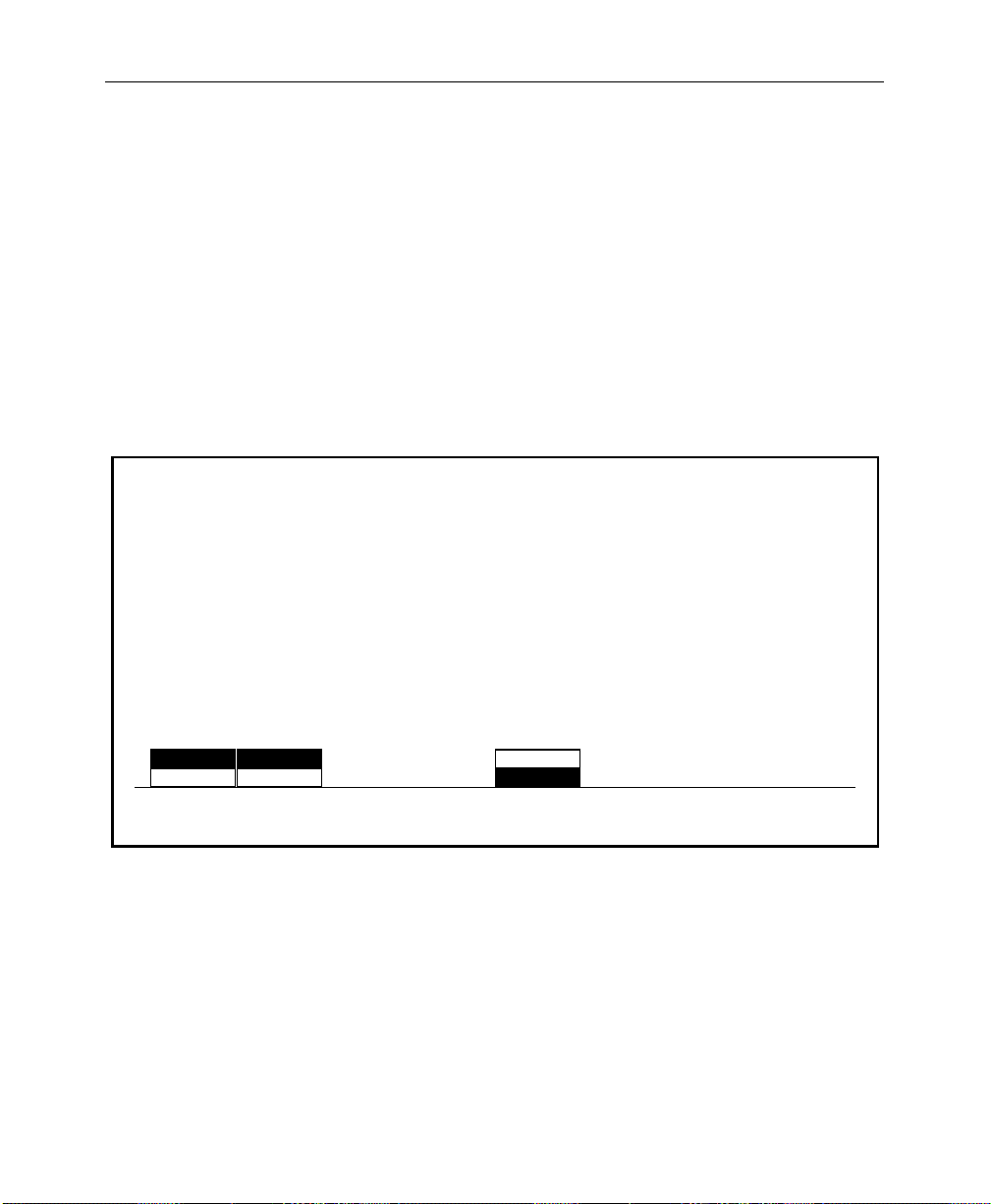
Section 2— Startup and Configuration
E-MEM Preferences
You may wish to customize the E-MEM system. E-MEM
preferences are selected on the Configuration/User Preferences
Menu/E-MEM User Preferences Menu shown below.
RUN LEVER — Use to enable or disable the E-MEM run lever.
KEYFRAME EDITING — Use to enable or disable keyframe editing.
MASTER E-MEM — Use to enable or disable 300-Style E-MEM
control.
E-MEM USER PREFS MENU
config / user prefs / E-MEM prefs
2-18
RUN
LEVER
ENABLEENABLE
DISABLEDISABLE
KEYFRAME
EDITING
300 STYLE<>
<>
<> <> <>MASTER
NORMAL
E-MEM
<><>
Page 51

Setting System Parameters
Use the System Parameters Menu to set the aspect ratio (ratio of
television picture width to height), to select the matte generator
chroma limiting algorithm, and to set the system clock.
Press the SYSTEM PARAMS > soft button below the Configuration
Menu display to bring up the System Parameters Menu:
SYSTEM PARAMETERS MENU
config/system param
XMITABLE
VALID RGB
BOTH
NONE
MATTE
GEN LIM
4 X 3
16 X 9
ASPECT
RATIO
FIELD 1
FIELD 2
NONE
FIELD
DOMINANCE
Software Setup
SET
CLOCK >
Note that some of these system parameters were set up during
installation.
ASPECT RATIO — Soft button may be set to either the 4 X 3 or 16 X 9
setting, depending on your installation requirements.
FIELD DOMINANCE — FIELD DOMINANCE set to NONE), selection
changes become effective at the beginning of the next field
(immediately after the functions have been changed).
2-19
Page 52

Section 2— Startup and Configuration
Using Field Dominance
If the Model 2200 output is going to be recorded onto tape that will
later be edited along with other tape, it is important that changes
take place consistently on the same field. They can occur on either
Field 1 or Field 2 of the frame, but need to be on the same field
every time. If this is not done, there will be a “flash” at the edit in
the resulting taped video.
With FIELD 1 selected as the dominant field, if a change takes place
just prior to Field 1, the change will become effective at the
beginning of Field 1. But if the change takes place prior to Field 2,
the change will be delayed by one field so that it also becomes
effective at the beginning of the next Field 1. This way, all changes
will be synchronized to take place at the beginning of Field 1.
Similarly, if
changes that take place prior to Field 1 would be delayed until
Field 2.
If you are recording the switcher output on video tape and will be
doing post-production editing of the tape, it is recommended that
you set Field Dominance for a specific field (either FIELD 1 or FIELD
2
), and leave it at that setting. This will ensure that all changes will
take effect consistently on the same field.
FIELD 2
were selected as the dominant field, those
2-20
If an Editor or a GPI trigger initiates one of these functions, it will
produce the same effect as a control panel change. That is, the
initiation of any of these functions will be delayed until the
beginning of the selected dominant field.
Page 53

Software Setup
The MATTE GEN LIM button is used to choose the matte generator
chroma limiting algorithm. The selections are:
XMITABL – Prevents the total signal (luminance and
chrominance) from exceeding the NTSC transmission
standard.
VALID RGB – Limits colors to those which generate red,
green, and blue values within the 0 to 100% range.
BOTH – Selects a valid RGB color limiter which also
prevents the encoded signal envelope from exceeding
NTSC transmission level. This is the system default
mode.
NONE – Turns off all algorithm methods for matte
generator limiting.
SET CLOCK> opens the Set Clock Menu which allows you to set the
system time and date.
2-21
Page 54

Section 2— Startup and Configuration
Setting the System Clock
Use the Set Clock Menu to set the system date and time.
1. From the System Parameters Menu, press the
SET CLOCK >
soft button to display the Set Clock Menu.
SET CLOCK MENU
config/system param/set clock
April 1, 1994
8:31 AM
Press "CONFIRM" button
to update the clock
DATE
TIME
SELECT CONFIRM
If the date and/or time are incorrect, they may be reset as
follows:
2. Set the date by selecting DATE with the SELECT button and
turning the soft knobs to select the appropriate (YEAR), (MONTH),
and (DAY).
3. Press the CONFIRM button to enter the new date.
CLOCK
setting.
YEAR
=1994
MONTH
= March
DAY
= 4
2-22
Page 55
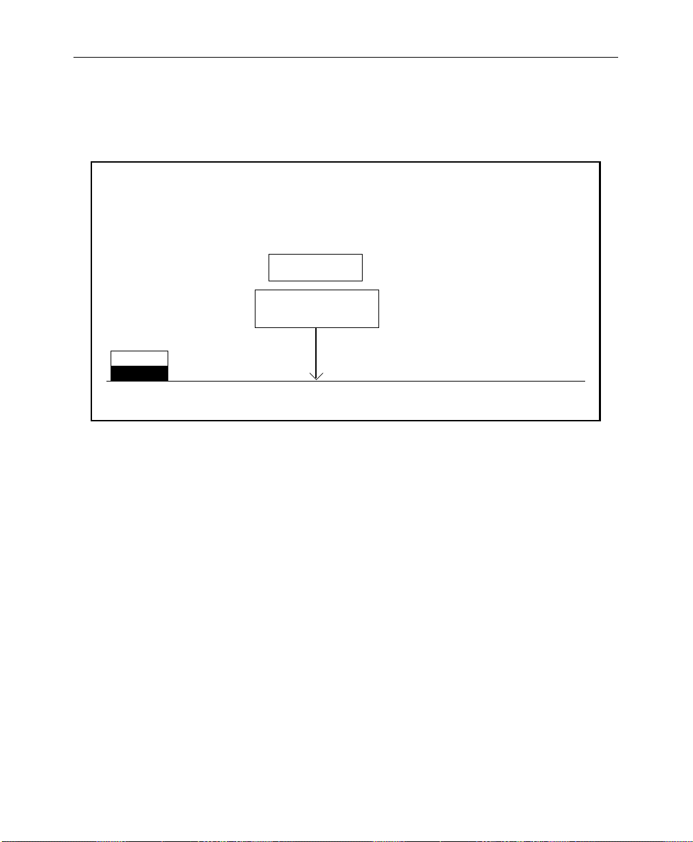
Software Setup
4. Set the time by selecting TIME with the SELECT button and using
the soft knobs to select the (HOUR), (MINUTE), and (SECOND).
SET CLOCK MENU
config / system param / set clock
December 5 1993
5:07:53 PM
Press "CONFIRM" button
to update the clock
DATE
TIME
SELECT CONFIRM
5. Press the CONFIRM button to enter the new time.
6. Press the top level CONFG button to return to the Configuration
Menu.
CLOCK
setting
HOUR
= 5 PM
MINUTE
= 7
SECOND
= 0
2-23
Page 56

Section 2— Startup and Configuration
Configuring Switcher Inputs
Primary video and key inputs to the switcher are numbered 1
through 64. Any of these inputs can be treated as either a video
signal or a key signal.
Each input, including Black and Background, can be mapped to
any vertical column of source select (“crosspoint”) buttons.
NOTE:
installation to correspond to the video and key inputs connected to the
frame. These assignments should never be changed by the operator.
Internally-generated sources (black, backgrounds, mask, etc.) are
also available for selection on the crosspoint matrix.
Thirty-two sources may be assigned at one time to the crosspoints
— 16 unshifted and 16 shifted selections. During the installation
procedure, each of the 32 input buses is assigned a video signal, a
key signal, and a chroma key signal.
All inputs are defined by function, name, crosspoint, input
number, and signal format.
Y ou may determine the input assignments and the characteristics
of the input signals through the use of the Configuration
submenus, as described in the following procedures.
The external video and key assignments are set up following
2-24
Page 57

Inputs
Software Setup
Use the Inputs Menu to enter or change the various configuration
settings for your inputs.
INPUTS MENU
/config/inputs
ANLG VIDEO
ANLG VIDEO
INPUTS >
INPUTS >
ANLG KEY
ANLG KEY
INPUTS >
INPUTS >
ANLG INPUT
ANLG INPUT
ANLG INPUT
TIMING >
TIMING >
TIMING >
MAP
INPUTS >
CHR KEY
INPUTS >
100% COLOR BARS
75% COLOR BARS
HORIZ TIMING
MULTIPULSE
PULSE & BAR
CHR KEY TEST
H RAMP
WALKING BITS
100% COLOR BARS
75% COLOR BARS
HORIZ TIMING
MULTIPULSE
PULSE & BAR
CHR KEY TEST
H RAMP
WALKING BITS
GPI
INPUTS >
TOP
TEST SIGNAL
BOTTOM
TEST SIGNAL
2-25
Page 58
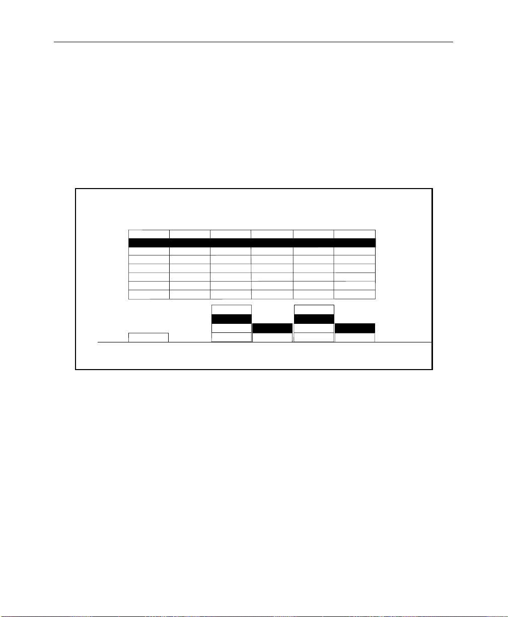
Section 2— Startup and Configuration
Setting Analog Video Inputs
Use the Analog Video Inputs Menu to select the component
format with setup or no setup for each analog video input.
1. From the Inputs Menu, press the ANLG VIDEO INPUTS > button to
select the Analog Video Inputs Menu as shown below.
ANALOG VIDEO INPUTS MENU
/config/inputs/anlg_vid_inp
INPUTS
CARD 1
CARD 2
CARD 3
CARD 4
CARD 5
CARD 6
CARD 7
CARD 8
CARD 2
CARD
SELECT
33-36
C0 4
37-40
41-44
45-48
49-52
53-56
57-60
61-64
BETA
BETA
BETA
BETA
BETA
BETA
BETA
BETA
RGB
BETA
YUV
MII
INP 37
FORMAT
OFF
OFF
OFF
OFF
OFF
OFF
OFF
OFF
OFF
ON
INP 37
SETUP
BETA
BETA
BETA
BETA
BETA
BETA
BETA
BETA
RGB
BETA
YUV
MII
INP 39
FORMAT
OFF
OFF
OFF
OFF
OFF
OFF
OFF
OFF
OFF
ON
INP 39
SETUP
2-26
2. Increment the CARD SELECT button until you reach the video
input you want to assign. There are 2 video inputs per card. In
the menu above a format is assigned to the video inputs on
Card 2 for inputs 37 and 39.
3. After formatting the input, you must determine whether the
video input requires SETUP or NO SETUP. Do this by selecting
ON or OFF for each input. The SETUP selection sets all outputs
for a black level 7.5 IRE above blanking. The NO SETUP
selection puts black at blanking level.
Page 59
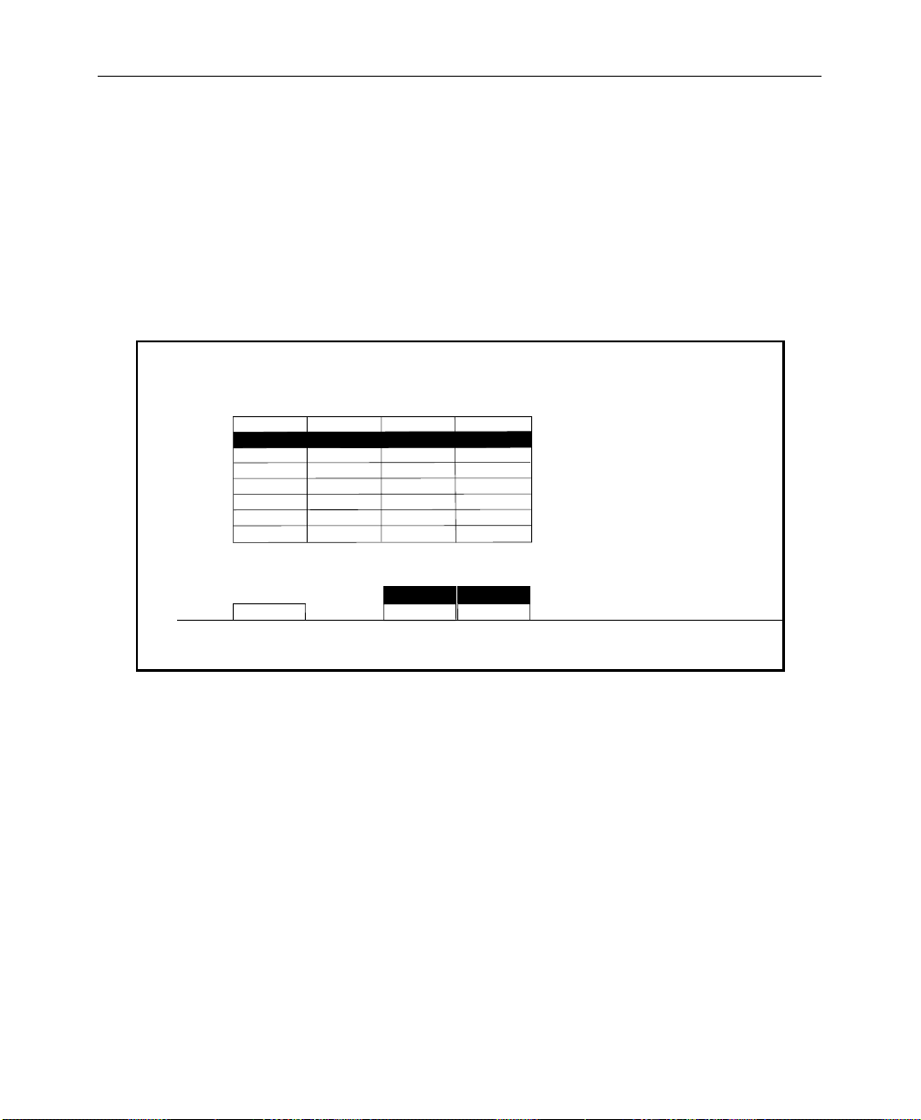
Setting Analog Key Inputs
Use the Analog Key Inputs Menu to select the component format
for each analog key input.
1. From the Inputs Menu, press the ANLG KEY INPUTS > button to
select the Analog Key Inputs Menu as shown below.
ANALOG KEY INPUTS MENU
/config/inputs/anlg_key_inp
INPUTS
CARD 1
CARD 2
CARD 3
CARD 4
CARD 5
CARD 6
CARD 7
CARD 8
33-36
C0 4
37-40
41-44
45-48
49-52
53-56
57-60
61-64
NO SETUP
NO SETUP
NO SETUP
NO SETUP
NO SETUP
NO SETUP
NO SETUP
NO SETUP
Software Setup
NO SETUP
NO SETUP
NO SETUP
NO SETUP
NO SETUP
NO SETUP
NO SETUP
NO SETUP
CARD 2
CARD
SELECT
NO SETUP
KEY SETUP
INP 38 INP 40
NO SETUP
KEY SETUP
2. Increment the CARD SELECT button until you reach the key
input you want to assign. There are 2 key inputs per card.
Here you are assigning a format to the key inputs on Card
2which handles key inputs 38 and 40.
3. After formatting the input, determine whether the key input
requires SETUP or NO SETUP . Do this by selecting KEY SETUP or
NO SETUP for each key input. The SETUP selection sets all
outputs for a black level 7.5 IRE above blanking. The NO SETUP
selection puts black at blanking level.
2-27
Page 60

Section 2— Startup and Configuration
Setting Analog Input Timing
Use the Analog Input Timing Menu to match the timing of each
analog/key input to the key bus. From the Inputs Menu, press the
ANLG INPUT TIMING > button to select the Analog Input T iming Menu.
ANALOG INPUT TIMING MENU
/config/inputs/anlg_inp_timing
INPUTS
CARD 1
CARD 2
CARD 3
CARD 4
CARD 5
CARD 6
CARD 7
CARD 8
CARD 2
CARD
SELECT
33-36
C0 4
37-40
41-44
45-48
49-52
53-56
57-60
61-64
1
1
1
1
1
1
1
1
1
2
3
4
INP 37-38
TIMING
1
1
1
1
1
1
1
1
1
2
3
4
INP 39-40
TIMING
2-28
1. Increment the CARD SELECT button until you r each the analog/
key inputs you want to time to the key bus. Here you are
timing all four inputs to the reference.
2. Use the INP “NN-NN” TIMING buttons to step the inputs in 1/4
clock increments (where 1 = the shortest delay, and 4 the
largest delay).
Page 61

Mapping Crosspoints
Use the Map Inputs Menu to define the format for each video or
key input.
Software Setup
MAP INPUTS MENU
config/inputs/map inputs
UNSHAPED
VIDEO
SHAPED
VIDEO
VIDEO/
KEY FMT
NOTE:
This function is applied to a key input only if the external key
is being used with video or superblack.
From the Inputs Menu, press the MAP INPUTS > button to select the
Map Inputs Menu.
VIDEO INPUT
= 4
KEY INPUT
= 1
= NONE
(INTERNAL)
XPT BUTTON
NUMBER
(SHIFT-14)
Use the Preset Bus to select button number.
38
XPT BUTTON
NAME
(DIG SER/RGB/SETUP)
(DIG SER/8 BIT/SETUP/SYNC)
CHROMA KEY INPUT
LOG CHANNEL
PHYS CHANNEL
LOG/PHYS
ASSIGNMENT
NAME XPT
BUTTON >
1. W ith the VIDEO/KEY FMT, button, select UNSHAPED VIDEO or SHAPED
VIDEO
. Inputs should be set for UNSHAPED VIDEO unless
otherwise required.
2. With the LOG/PHYS ASSIGNMENT button, select
PHYS INPUTS.
3. Press the crosspoint button on the PST bus that you want to
map. (All crosspoints in that vertical column will have the
same inputs.)
2-29
Page 62

Section 2— Startup and Configuration
4. Use the appropriate soft knob to select the desired type of
input. Note that input formats are displayed when selecting
input type.
NOTE:
5. If mapping a chroma key input, use the CHROMA KEY INPUT soft
Refer to “DPM Map Aux Bus Menu” under “DPM Configuring,”
in this section, for use of the LOG CHANNEL function of the LOG/PHYS
ASSIGNMENT
Undefined buttons default to black.
knob to assign the chroma key type for the currently selected
crosspoint button.
button.
2-30
Page 63

Naming Crosspoint Buttons
After mapping the input, you may name the crosspoint by
pressing NAME XPT BUTTON >. The Name Xpt Button Menu appears
as shown below.
Software Setup
NAME XPT BUTTON MENU
config/inputs/map inputs/name xpt button
String Register
Camera
Save
ACCEPT
CHAR
Get
String
Use the Preset Bus to select button number.
CURSOR
FORWRD
Button Name
Cam 2
Character = G
CURSOR
BACK
String
1. Select each character by turning the soft knobs located to
the right of the menu display.
2. Enter the selected character by pressing the ACCEPT CHAR
button. The new character will be displayed in the menu.
3. Continue selecting characters in this manner until the name is
spelled out in the menu. You may enter up to 9 characters for
the input name.
space ' ( ) - / * : .
a b c d e f g h i j k l m n o p q r s t u v w x y z
38
DELETE
CHAR
G
1 2 3 4 5 6 7 8 9 0
SAVE
STRING
GET
STRING
ACCEPT
NAME
A B C D E F G H I J K L M N O P Q R S T U V W X Y Z
XPT BUTTON NUMBER
(SHIFT- 14)
4. Press ACCEPT NAME to store the name. The system
automatically returns to the Map Inputs Menu.
5. Repeat the steps in Mapping Crosspoints and Naming
Crosspoint Buttons until all inputs have been mapped and
named.
2-31
Page 64
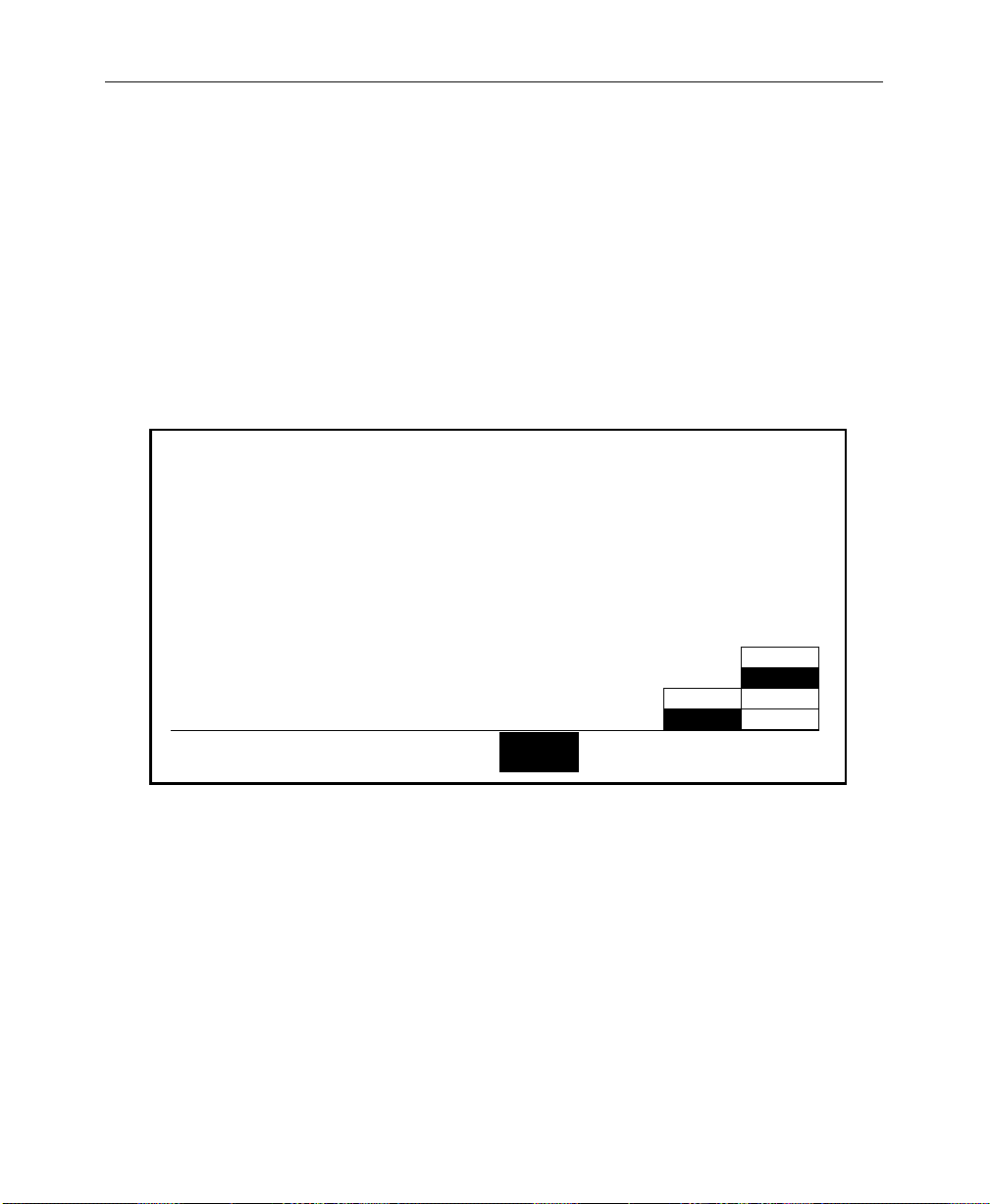
Section 2— Startup and Configuration
Formatting Chroma Key Inputs
If you have installed the optional Chroma Key Inputs, you need to
assign input formats. Use the Chroma Key Inputs Menu to select
and adjust chroma key parameters.
1. From the Chroma Key Inputs Menu, select the appropriate
input to change. As each button is pressed, the input format
will change to the default setting for that input.
CHROMA KEY INPUTS MENU
config/inputs/chr key inputs
COARSE
TIMING = 24.25 CLOCKS
=(24.250 µsecs)
FINE
2-32
INPUT
1
RGB
BETA
YUV
M II
INPUT
FORMAT
INPUT
2
INPUT
3
INPUT
4
INPUT
5
INPUT
6
OFF
ON
SETUP
2. As required, either accept the default input format, or change
it to match the chroma key input signal format. Adjust the
coarse and fine timing for each chroma key input. The range
of the COARSE soft knob is –256 clocks to +256 clocks. Use the
FINE soft knob to adjust the fractional value from .000 to .999
clocks.
3. Choose SETUP either ON or OFF for the selected Chroma Key
Input (1 through 6).
4. Press EXIT to return to the Inputs Menu.
Page 65

Assigning GPI Inputs
Use the GPI Inputs Menu to set GPI assignments for signals that
can be used to trigger Model 2200 functions. These assignments
must correspond to the physical GPI connections described earlier
in this section.
Eight GPI inputs are provided. All of these accept pulse-type GPI
inputs except Aux Tally Back, which is level-sensitive.
1. From the Inputs Menu, press the GPI IN> button to select the
GPI Inputs Menu. (The first time you do this no functions will
appear in the second column of the menu table.)
Software Setup
GPI INPUTS MENU
config / inputs / gpi inputs
GPI 1
GPI 2
GPI 3
GPI 4
GPI 5
GPI 6
GPI 7
GPI 8
GPI 1
GPI
SELECT
AUX TALLY - BUS 1
M/E 1 AUTO TRAN
M/E 1 CUT
RUN EFFECT
MASTER RECALL EFF - 26
GPI DISABLED
FRAME STORE VIDEO GRAB
SEQUENCE MODE
MISC
FUNCTION SELECT
LOG CHAN
When the desired function is selected,
press PROGRAM GPI button to set the
selected GPI input to the
selected function
Choose from these 6 buttons to select various
categories of GPI functions. Then use the
FUNCTION SELECT knob to select a function
KF
EFFECT
AUTO
TRANS E-MEMCUT
AUX
TALLY
FRAME
STORE
TALLY
The types of GPI assignments currently available are
Miscellaneous (Aux Tallies), Keyframe Effects, Auto
Transitions, Cuts, E-MEM registers, and Frame Stores, as
indicated by the button labels at the bottom of the display
window .
One of these functions is always selected. The selected
function is indicated in parentheses under the
SELECT
knob label.
(MISC)
DISABLE
GPI
AUX BUS
AUX TALLY
BUS 1?
PROGRAM
GPI
FUNCTION
= 1
2-33
Page 66

Section 2— Startup and Configuration
2. To assign the GPI inputs, first press GPI SELECT to select the
desired input.
3. Select the type of category to be assigned (Misc, Auto Trans,
etc.) by pressing the appropriate soft button.
4. Turn the FUNCTION SELECT knob to assign a specific function
(Aux Tally, etc.).
5. After the desired function has been selected for each GPI,
press PROGRAM GPI to enter the selection, which is indicated in
the display table.
The following categories are available for assignment:
MISC — Enables selection of the Aux Tally Back function,
or allows the selected GPI input to be disabled.
AUX TALLY — Allows an external device to control the
aux bus tally level (high or low). The (AUX BUS) soft
knob selects the appropriate aux bus.
2-34
DISABLE GPI — Causes any signal applied to the
selected GPI input to be ignored.
KF EFFECT — Enables selection of the Keyframe GPI
function. The following functions may be triggered with
GPI pulses:
RUN, REWIND, AUTO RUN, and REVERSE
Page 67

Software Setup
AUTO TRANS — Enables selection of the Auto T ransition GPI
function. The following transitions may be triggered with
GPI pulses:
M/E 1, M/E 2, F-F, and F-F PST BLK
CUT
— Enables selection of the Cut GPI function. The
following cuts may be triggered by the GPI:
M/E 1, M/E 2, and F-F
E-MEM
— Enables selection of the E-MEM GPI function.
The following E-MEM functions may be triggered by the
GPI:
RECALL ME 1, RECALL ME 2, RECALL MSTR, AUTO RECALL, EFX
DISSOLV, AND SEQUENCE.
the register for E-MEM recalls.
FRAME STORE — Enables selection of the Frame Store GPI
function. The functions that may be triggered are:
VIDEO GRAB, KEY GRAB, and MASK GRAB
The REGISTER soft knob selects
2-35
Page 68

Section 2— Startup and Configuration
Configuring Outputs
Select OUTPUTS from the Configuration Menu. The OUTPUTS Menu
shown below appears:
OUTPUTS MENU
config/outputs
PGM
M/E1 PGM
M/E2 PGM
PGM
OUTPUT
SELECT
PEAK WHITE
OFF
BOTH
OFF
PEAK WHITE
PEAK BLACK
BOTH
LUM
LIMITER
OFF
PEAK
PEAK
OFF
PEAK
CHROM
LIMITER
DIGITAL
RES>
1. Select the desired output from PGM, M/E 1 PGM or
M/E 2 PGM with the OUTPUT SELECT button.
2. With the LUM LIMITER button choose between the following
luminance limiting condition for the delegated PGM video
output (does not apply to reentries):
■ PEAK WHITE — the luminance level is not allowed to go
above peak white luminance
■ PEAK BLACK — the luminance level is not allowed to go
below standard black luminance
■ BOTH — keeps the luminance levels between standard
black and peak white
2-36
■ OFF — allows the luminance levels to vary between the
full legal D1 limits
Page 69

3. Use the CHROM LIMITER button to set the chrominance to the
following conditions:
■ PEAK — keeps the chrominance between 100% chroma
saturation levels
■ OFF — allows chrominance levels to vary between the full
legal D1 limits
Setting Output Resolution and Dither
The Output Digital Resolution Menu allows you to set digital
outputs to either 8-bit or 10-bit resolution with dithering on or off.
The type of output dictates which combination of resolution and
dither on/off that may be selected. The combinations are:
Table 2-1. Output Dither Settings
Output Selection Resolution Dither
Software Setup
M/E 1 PGM
M/E 2 PGM
DSK PGM
DSK CLEAN
AUX 1
AUX 2
M/E 1 PVW
M/E 2 PVW
DSK PVW
DSK DIRTY
10-bit ON
10-bit OFF
8-bit ON
8-bit OFF
10-BIT OFF
8-BIT ON
2-37
Page 70
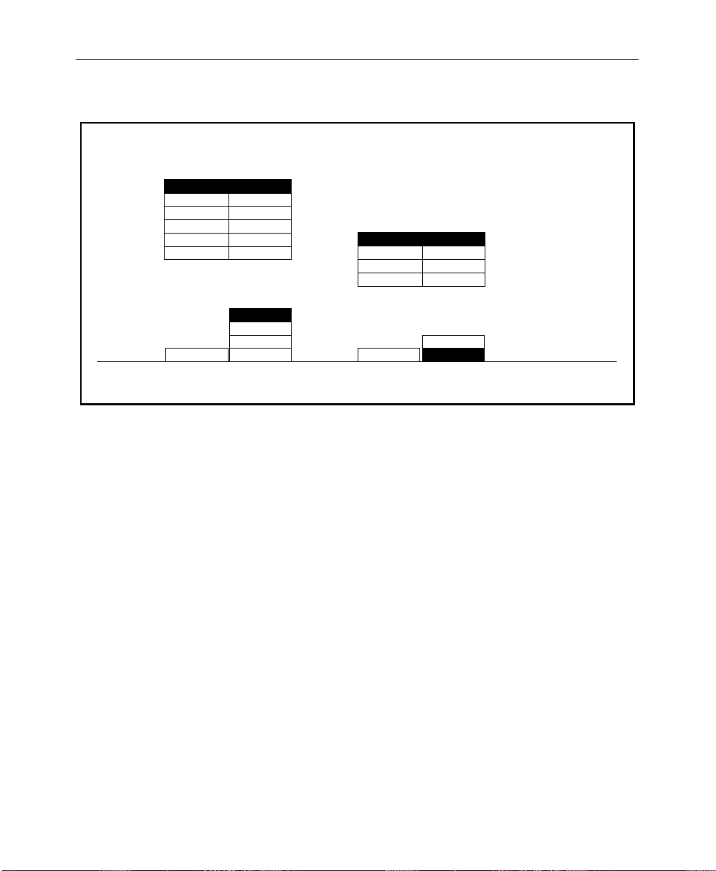
Section 2— Startup and Configuration
OUTPUT DIGITAL RESOLUTION MENU
config / outputs / digital res
M/E 1 PGM 10 BIT/ON
M/E 1 CLEAN
M/E 2 PGM
M/E 2 CLEAN
AUX 1
AUX 2
OUTPUT
SELECT
10 BIT/ON
10 BIT/ON
8 BIT/ON
8 BIT/ON
8 BIT/ON
10 BIT/ON
10 BIT/OFF
8 BIT/ON
8 BIT/OFF
RESOLUTION/
DITHER
M/E 1 PVW 8 BIT/ON
M/E 2 PVW
DSK PVW
DSK DIRTY
M/E 1 PVWM/E 1 PGM
OUTPUT
SELECT
8 BIT/ON
8 BIT/ON
8 BIT/ON
10 BIT/OFF
8 BIT/ON
RESOLUTION/
DITHER
2200
2-38
Page 71

Configuring External Interfaces
The External Interface menus set the operating parameters for the
Editor Interface, DPM Interface, and the GPI Interface. The
External Interface Menu is shown below:
EXTERNAL INTERFACE MENU
config/extern if
Software Setup
EDITOR
I/F>
DPM
I/F>
PERIPHERAL
I/F>
GPI
OUTPUTS>
Press the EDITOR I/F> button to advance to the Editor Menu.
NOTE:
DPM I/F and PERIPHERAL I/F Menu descriptions and
functions are included in the next section. See “DPM Configurations”
on page 2-42.
2-39
Page 72
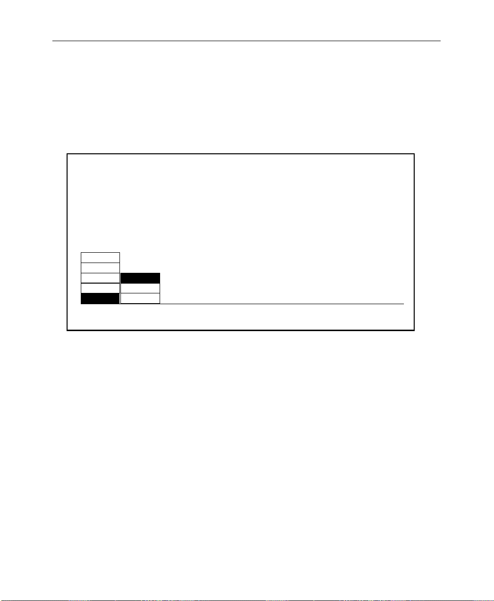
Section 2— Startup and Configuration
Setting Editor Port Parameters
The Editor Interface Menu shown below allows you to set the
Baud, Parity and Switcher Address for the switcher editor port, J3,
on the Com I/O Module in Slot C1.
EDITOR INTERFACE MENU
config/extern if editor if
2400
4800
9600
BAUD PARITY
ODD
EVEN19200
NONE38400
1. Select the desired switcher editor port BAUD rate with the
BAUD button. The choices are listed below:
■ 2400
■ 4800
■ 9600
■ 19200
SWITCHER ADDRESS
= 30 hex
2-40
■ 38400 (Typical setting for Grass Valley editors.)
2. Select the desired parity for the switcher editor port with the
PARITY button. The choices are listed below:
■ ODD (Typical setting for Grass Valley editors.)
✮ EVEN
✮ NONE
Page 73

Configuring GPI Outputs
Use the GPI Outputs Menu to set E-MEM levels for each assigned
GPI. Y ou can also set up GPI outputs which trigger each time there
is a cut on the PGM Bus, and set the length of the GPI trigger
signal. This menu is accessed from the Config/External If Menu.
Software Setup
GPI OUTPUTS MENU
config / external if / gpi outputs
OFF
GPI 1
GPI 2
GPI 3
GPI 4
GPI 5
GPI 6
GPI 7
GPI 8 7
PGM CUT
TRIGGER
1. Use the PGM CUT TRIGGER button to select a GPI number which
will trigger each time there is a cut on the PGM Bus. This GPI
is typically connected to an external device such as a clock/
timer which is reset by each trigger. Such a clock would then
indicate how long the current source has been on air.
2. Use the
LENGTH
= 1 Field
1 MISC
2 MISC
3 MISC
4 MISC
5
6
7
8
SELECT
GPI
LEVEL LENGTH
1
1
1
1
MISC
MISC
MISC
MISC
MISC
DPM 1
DPM 2
DPM 3
DPM 4
E-MEM
LEVEL
1
1
1
1
SELECT GPI button to select the desired GPI number.
3. Press the E-MEM LEVEL button to select the desir ed E-MEM level
for the selected GPI number.
4. Use the LENGTH soft knob to select (in number of fields) the
required GPI duration. Use this to set the duration of GPI
output triggers.
5. Repeat Steps 1 through 3 for other GPIs.
2-41
Page 74

Section 2— Startup and Configuration
DPM Configurations
Digital Picture Manipulators (DPMs) are external video devices
connected to the switcher. In this discussion, reference is also
made to DPM levels, which are E-MEM levels into which DPMassociated information is learned. The combined system
capabilities of the switcher and DPMs depend on:
■ The video connection
■ The capabilities of the DPM
■ The control connection
It is not necessary to have a control connection from the switcher
to a DPM; however, the highest level of system integration is
achieved where there is a control connection.
The Video Connection (Aux Buses and Return Inputs)
A normal video signal path consists of an aux bus output fr om the
switcher feeding a DPM input and the DPM output returned to a
switcher input which is mapped to a switcher source select
button.
2-42
The video path through a DPM introduces a video delay into the
system. For example, Kaleidoscope introduces a 2-field video
delay.
NOTE:
If the video delay is not set correctly, ther e will be a glitch in the
video upon entering Effects Send mode.
There are four steps in configuring the video path:
■ Aux buses are assigned to DPMs using the DPM Map Aux
Buses Menu
■ Return input connections are configured using the DPM Map
Inputs Menu
■ The mapping of a return connection to a crosspoint is done
using the Configuration/Map Inputs Menu
■ The video delay is set using the DPM Setup Menu
Page 75

Software Setup
The system defaults to all aux buses being part of the MISC E-MEM
level. When an aux bus is configured for use with an external
DPM, its settings are no longer saved in the MISC level but are
saved in the relevant DPM level when an E-MEM register is
learned. Information (such as aux bus crosspoint selection) is
learned for each DPM on separate E-MEM levels.
In cases where it is not desirable to have an aux bus selection
learned/recalled on the MISC level, it is possible to configure the
aux bus to a DPM level (such as DPM 4) and never enable that level.
An example would be if the aux bus were controlled by a Remote
Aux panel.
DPM Capabilities (Fixed and Pooled)
The characteristics of the DPM are configured in the DPM Setup
Menu. The first choice to be made is selection of DPM TYPE from
NONE, KSCOPE, OTHER POOL
The DPM TYPE of NONE indicates that there is no external DPM
device used for the particular DPM level. However , it can also be
used for cases where aux buses are assigned to a DPM level, but
there is no physical device, no return signal, and no control
connection (for example, an aux bus dedicated to feeding a video
monitor).
1
, or OTHER FIXED.
Both KSCOPE and OTHER POOL are selections for pooled devices.
A pooled device is one which provides acquisition of logical
channels from a pool of physical channels.
Kaleidoscope is a pooled device. As an example, consider a
Kaleidoscope having 5 physical channels named A, B, C, D, and E.
The pooled channels are shared by different users. A user may
build a Kaleidoscope effect using 3 channels. On one day he may
acquire physical channels C, D, and E as logical channels 1, 2, and
3; on another day he may acquire physical channels B, C, and D as
logical channels 1, 2, and 3. The same effect will perform
identically on both configurations since the operator’s view of the
1. OTHER POOL is reserved for future use. It is for DPMs other than Kaleidoscope which are pooled
and use CPL to communicate.
2-43
Page 76

Section 2— Startup and Configuration
system is the logical arrangement of channels (1, 2, 3), not the
physical channels used.
In systems with multiple DPM channels, it is desirable to have a
predictable relationship between aux buses and DPM channels
(e.g., aux bus 1 feeding DPM channel 1, aux bus 2 feeding channel
2, etc.). It is also desirable to have a particular switcher crosspoint
button always select the same DPM channel return input. For a
fixed device (such as the DPM-700) this relationship is achieved
by cabling alone. For a pooled device, such as Kaleidoscope, the
Model 2200 achieves predictable DPM channel routing by
maintaining an extra level of mapping between physical and
logical DPM channels. This mapping, termed Switcher Input
Routing and Switcher Output Routing, is discussed on the
following page.
DPM TYPE of OTHER FIXED or NONE (DPMs which are not pooled
For
and do not have Input and Output Routing), the CHANNEL ROUTING
selection should be OFF.
Kaleidoscope changes its logical-to-physical channel mapping,
depending on the order in which channels are acquired from its
pool. Switcher output routing maps a physical aux bus to a logical
aux bus so that the logical aux bus number corresponds with the
DPM’s logical channel.
2-44
The Aux bus button selection made on the switcher control panel
is always a logical aux bus; however, unless Kaleidoscope is
connected, Logical Aux Bus 1 always corresponds to Physical Aux
Bus 1, etc. (The current mapping of physical-to-logical DPM
channels is displayed in the DPM Map Inputs Menu.)
It should be noted that the switcher supports only one pooled
device. Also, the pooled device must be cabled so that the first
physical aux bus is connected to the first physical channel. In the
example in Figure 2-3, Physical Aux Bus 1 is connected to
Kaleidoscope Physical Channel A, Bus 2 to Channel B, and so on.
Page 77

Model 4000
Kaleidoscope
Physical
Channels
Software Setup
0347-02-29
EDCBA
Switcher
Input
Routing
Logical Aux 1
Logical Aux 2
Logical Aux 3
Logical Aux 4
Logical Aux 5
Logical Aux 6
Logical Aux 7
Kaleidoscope
Channel Pool
A
C
E
Effects Send Capable Video
Non-Effects Send Video
Logical
Channel
1
Logical
Channel
2
Kaleidoscope
Logical Channels
Logical
Channel
3
Logical
Channel
Logical
Channel
4
Switcher
Output
Routing
5
Phys Aux 1
Phys Aux 2
Phys Aux 3
Phys Aux 4
Phys Aux 5
Figure 2-3. Example of Connections for a Pooled DPM
For a particular studio session, three Kaleidoscope channels could
be acquired from the pool in the order D, E, A, which would be
logical channels 1, 2, 3. This mapping information is passed from
the DPM to the switcher via the control connection. Switcher
output routing ensures that the logical channels 1, 2, 3 appear to
the user on logical aux buses 1, 2, 3 and switcher input routing
ensures that DPM logical channels 1, 2, 3 appear on the
crosspoints configured for these logical channels. For the above
configuration, the selection of CHANNEL ROUTING in the DPM Setup
Menu should be set to BOTH.
B
D
2-45
Page 78

Section 2— Startup and Configuration
There are circumstances wher e output routing is not desirable. For
example, the DPM may have more than 5 channels. In that case, a
router or patch panel may be inserted between the switcher and
Kaleidoscope (Figure 2-4). In this example, switcher output
routing is turned off, so the menu selection for CHANNEL ROUTING in
the DPM Setup Menu should be set to SWR IN. This still provides
the return video from the switcher being on a consistent
crosspoint.
16 Inputs
Model 4000
Switcher
Input
Routing
Aux 1
Aux 2
Aux 3
Aux 4
Aux 5
Aux 6
Aux 7
Logical
Channel
1
Logical
Channel
2
Kaleidoscope
Logical Channels
Logical
Channel
HGFEDCBA
Logical
Channel
5
Logical
Channel
4
3
Aux Bus Outputs
From Other Suites
Router/
Patch Panel
0347-02-30
Kaleidoscope
Channel Pool
A
B
C
D
E
F
G
H
To Other Suites
Effects Send Capable Video
Non-Effects Send Video
2-46
Figure 2-4. Example of Connections Using an External Router
Page 79

Software Setup
Control Connection
Three forms of control connection to the DPMs are supported.
These are
■ CPL (Control Point Language)
■ PBusII (Peripheral Bus II)
■ GPIs
Control Point Language — CPL is the communication protocol used
to couple the switcher and Kaleidoscope. One of its uses is to
convey the physical-to-logical channel mapping information
described previously. It is also used for run control of effects, aux
bus selection (including front/back switching) and tally.
DPM TYPE is set to either KRYSTAL or KSCOPE in the DPM Setup
When
Menu, CPL is automatically invoked. PORT ASSIGN should be set to
PORT A1.
Also, when either KRYSTAL or KSCOPE is selected as the DPM TYPE,
aux bus control is automatically assigned to
Krystal/Kaleidoscope. With Krystal/Kaleidoscope controlling
the aux buses, when a source button is selected on the
Krystal/Kaleidoscope panel, that source button is also selected on
the switcher for that aux bus, and vice versa. So an effect running
on Krystal/Kaleidoscope can cause the switcher to select different
crosspoints. This is the mechanism used to achieve front/back
switching.
All control connections have an associated control delay. The
CONTROL DELAY in the DPM Setup Menu should be set to 6 fields
when the DPM TYPE is set to either KRYSTAL or KSCOPE.
When any other type of DPM is selected as the DPM TYPE, the Model
2200 Switcher controls the aux bus.
2-47
Page 80
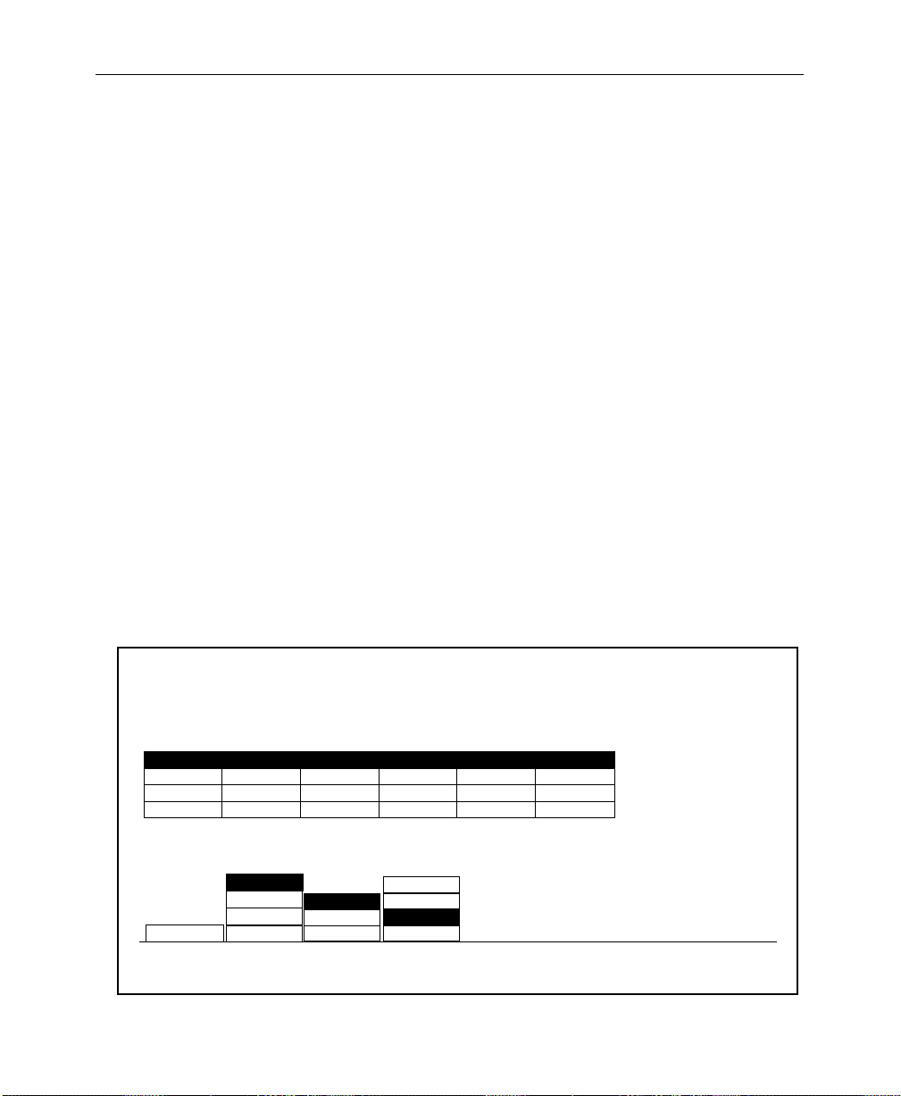
Section 2— Startup and Configuration
Peripheral Bus II (Port A3 Only) — PBusII is used for r un control of
effects using triggers. With current software, PBusII triggers are
learned into the MISC E-MEM level. For example, when using
PBusII as the control connection for a DPM-700, the following
should be set in the DPM Setup Menu:
PORT ASSIGN = NONE
CHANNEL ROUTING = OFF
GPIs—Both input and output GPIs may be used as triggers as part
of the control interface between the DPM and switcher.
Depending on the nature of the DPM, GPIs can be used for effect
recall and run control, source selection, and tally information.
Configuring the DPM Interface
Set up the DPM type, port assignment, channel routing, video
delay, and control delay as follows:
From the External Interface Menu, press DPM IF> to bring up the
DPM Setup Menu.
DPM SETUP MENU
config / extern if / dpm setup
2-48
DPM 1 BOTHPORT A1 62
DPM 2
DPM 3
DPM 4
DPM 1
DEVICE
SELECT
KRYSTAL
OTHER FIXED
KSCOPE
NONE
NONE
KSCOPE
KRYSTAL
NONE
DPM
TYPE
NONE
NONE
NONE
PORT A1
PORT A2
NONE
PORT
ASSIGN
-
-
-
SWR IN
SWR OUT
BOTH
OFF
CHANNEL
ROUTING
2
0
0
CTRL DELAYVIDEO DELAY
6
0
0
K'SCOPE
SOURCES>
CONTROL DELAY
DPM MAP
AUX BUSES >
VIDEO DELAY
= 2 fields
= 6 fields
DPM MAP
INPUTS >
Page 81

Software Setup
For Kaleidoscope:
1. Set the DPM TYPE to KSCOPE.
2. T urn the VIDEO DELAY soft knob to select 2 FIELDS . It is important
to set this delay correctly.
3. Turn the CONTROL DELAY soft knob to select 6 FIELDS.
4. Press the PORT ASSIGN button to assign PORT A1 to the DPM.
The baud rate for Port A1 is fixed at 307 K baud.
5. Set CHANNEL ROUTING for BOTH or SWR IN, depending upon your
system configuration, as described previously under “DPM
Configurations.”
6. Reset the Control Processor in the Model 2200 Signal
Processor frame. This is done by opening the front door of the
Processor and pressing the RESET button located near the
top of the Control Processor module.
Communication should now be established between the Model
2200 and Kaleidoscope.
For Krystal:
1. Set the
2. T urn the VIDEO DELAY soft knob to select 2 FIELDS . It is important
to set this delay correctly.
3. Turn the CONTROL DELAY soft knob to select 6 FIELDS.
4. Press the PORT ASSIGN button to assign PORT A1 to the DPM.
The baud rate for Port A1 is fixed at 307 K baud.
5. Set CHANNEL ROUTING for BOTH or SWR IN, depending upon your
system configuration, as described previously under “DPM
Configurations.”
6. Reset the Control Processor in the Model 2200 Signal
Processor frame. This is done by opening the front door of the
DPM TYPE to KRYSTAL.
2-49
Page 82

Section 2— Startup and Configuration
Processor and pressing the RESET button located near the
top of the Control Processor module.
Communication should now be established between the Model
2200 and Krystal.
For a DPM-700:
1. Set the DPM TYPE, to OTHER FIXED.
2. Set AUX BUS CONTROL to SWITCHER. (The DPM-700 cannot
control the aux bus.)
3. T urn the VIDEO DELAY soft knob to select 2 fields. It is important
that this be set correctly.
The CONTROL DELAY soft knob has no effect with the
DPM-700.
4. Set PORT ASSIGN to NONE.
5. Set CHANNEL ROUTING to OFF.
2-50
Page 83

Kaleidoscope Source Button Mapping
The DPM K’Scope Sources Menu, shown below, allows you to
map Kaleidoscope video source crosspoints to your switcher
video source crosspoints. The first time you use this menu you
must set user defaults. After setting defaults you can map
crosspoints as required.
Map Kaleidoscope video source crosspoints as follows:
1. From the DPM Setup Menu, press DPM K’SCOPE SOURCES> to
access the DPM K’Scope Sources Menu.
2. Push SET DEFAULTS to set user defaults.
3. Scroll the menu table selection fields with the K’SCOPE BUTTON
soft knob. Highlight the K’Scope button number you want to
map.
4. Use the SWITCHER BUTTON soft knob to set the desired switcher
video source crosspoint to the Kaleidoscope video source
crosspoint
Software Setup
DPM K'SCOPE SOURCES MENU
config/extern if/dpm setup/dpm k'scope sources
K'SCOPE BTN K'SCOPE BTN K'SCOPE BTN
0
12
23
3
4
56
67
78
89
9
10
SET
DEFAULTS
SWR BTN SWR BTN SWR BTN
1
4
5
10
11
11
12
13
14
15
16
17
18
19
20
21
12
13 23
14
16
17 27
18 28
19 29
20 30
21 31
22
22
24
2515
26
23
24
S/1
S/2
S/3
S/4
S/5
ME/1
ME/2
PGM
DIAL IN SWITCHER
XPT BUTTON FOR
K'SCOPE SOURCE
BUTTON
K'SCOPE BUTTON
SWITCHER BUTTON
2-51
=
=
Page 84

Section 2— Startup and Configuration
Mapping DPM Aux Buses
Set up the aux bus-to-device assignment as follows:
1. From the DPM Setup Menu, press DPM MAP AUX BUSES> to
access the DPM Map Aux Buses Menu.
DPM MAP AUX BUSES MENU
config/extern if/dpm setup/dpm map aux buses
Connection of physical AUX buses
to physical channels
AUX 4
CHAN 1
DPM 1
DPM 2 AUX 6 AUX 7 - - - ---
DPM 3
DPM 4
DPM 2
DEVICE
SELECT
AUX 1
AUX 5MISC - - - -
CHAN 2
AUX 2
-
-
CHAN 3
AUX 3
-
-
CHAN 4
-
-
-
-
-
2. Select the desired device (1 through 4) by pressing the DEVICE
SELECT
button
3. For Kaleidoscope, rotate the NUMBER OF CHANNELS knob,
assigning aux buses 1 through ‘n’ to this device number . Note
that a Kaleidoscope device (or other poolable DPM) does not
allow you to select a starting aux bus number other than Aux
Bus 1.
-AUX 8
CHAN 5
-
-
-
CHAN 6
-
-
-
NUMBER OF CHANNELS
CHAN 7
CHAN 8
-
-
-
-
-
-
= 2
CHANNEL 1
= AUX 6
2-52
Page 85

Software Setup
For example:
T o use Kaleidoscope physical Channel D, you must assign
at least 4 physical aux buses to DPM use (physical Aux 4
mapped to physical Channel D).
NOTE:
4. For DPM 100 or 700 set the NUMBER OF CHANNELS and CHANNEL
NOTE:
under the DPM level, rather than the MISC level for E-MEM
operations.
Press the EXIT button to return to the DPM Setup Menu.
Some examples of connecting switcher(s) to Kaleidoscope is
shown below. See examples 1 and 2.
All aux buses assigned to a DPM must be in consecutive order .
1=
soft knobs as appropriate for your installation.
Assigning an Aux Bus to a DPM level saves the parameters
2-53
Page 86
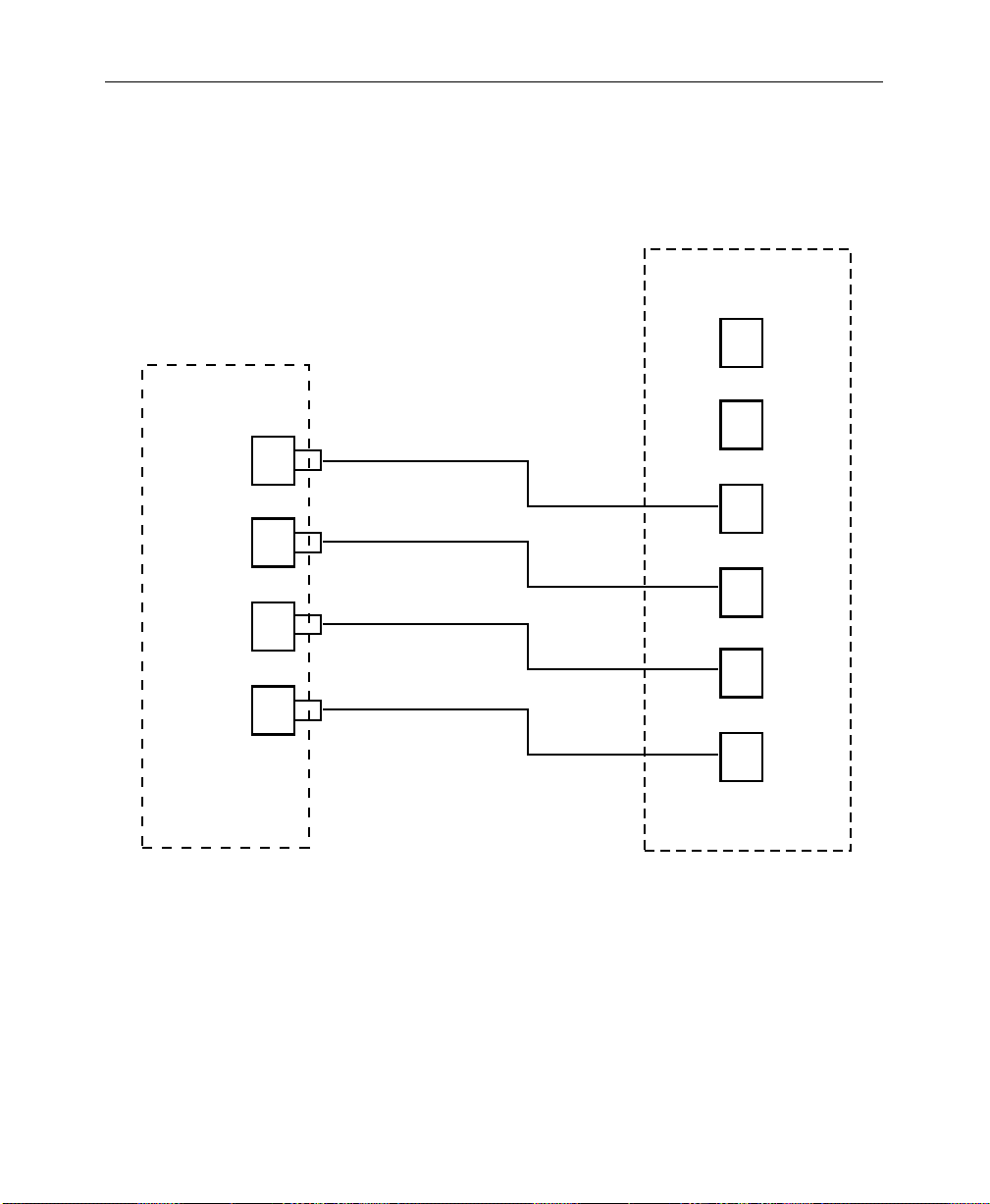
Section 2— Startup and Configuration
Example 1: Switcher-to-Kaleidoscope Configuration
Aux
Bus
1
2
3
Physical Channel
A
B
C
D
2-54
Switcher
E
4
F
Kaleidoscope
Figure 2-4. Switcher-to-Kaleidoscope Cabling – Ex. 1
Page 87

Software Setup
Example 2: Switcher-to-Kaleidoscope Configuration
Switcher 1
Aux
Bus
1
2
3
4
Aux
Bus
1
2
Physical
Channel
A
B
C
D
E
F
3
4
Switcher 2
Kaleidoscope
Figure 2-5. Switcher-to-Kaleidoscope Cabling – Ex. 2
G
H
2-55
Page 88

Section 2— Startup and Configuration
The following sample menu shows how you might set up the
DPM Map Aux Buses Menu for use with Kaleidoscope.
DPM MAP AUX BUSES MENU
config/extern if/dpm setup/dpm map aux buses
Connection of physical AUX buses
to physical channels
AUX 6MISC
CHAN B
-
-
-
CHAN C
---
-
-
-
CHAN D
--------
-
-
-
-
PHYS CHAN
DPM 1
DPM 2
DPM 3
DPM 4
DPM 1
DEVICE
SELECT
AUX 5
CHAN A
NUMBER OF CHANNELS
-AUX 7
CHAN E
AUX 1 AUX 2 AUX 3 AUX 4
-
-
---
CHAN F
CHAN G
-
-
CHAN H
----
-
-
FIRST CHANNEL
= CHAN E
-
-
= 4
2-56
Page 89
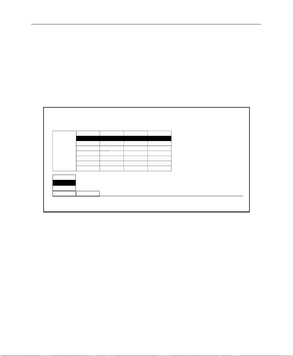
Mapping DPM Inputs
Set up the Kaleidoscope video and key return input numbers as
follows:
1. From the DPM Setup Menu, press DPM MAP INPUTS> to bring up
the DPM Map Inputs Menu.
Software Setup
DPM MAP INPUTS MENU
config/extern if/dpm setup/dpm map inputs
VIDEO INPUT
DPM 2
DPM 1
DPM 2
DPM 3
DPM 4
DPM
SELECT
CHAN 1-PRI
CHAN 2
CHAN 3
CHAN 4
CHAN 5
CHAN 6
CHAN 7
SECONDARY
CHAN 2
CHANNEL
SELECT
LOGICALPHYSICAL
2. Select the desired device (1 through 4) by pressing the DPM
SELECT
button.
3. Select the desired DPM channel by pressing the CHANNEL
SELECT
button.
4. Use the VIDEO INPUT knob to assign an input (1 - 64) to the
Model 2200 physical channel to which the Kaleidoscope
physical channel video return is connected.
KEY INPUT
6
19 42
29
-
-
-
-
-
VIDEO INPUT
= 19
23
KEY INPUT
63
-
-
-
-
-
= 42
5. Use the
KEY INPUT knob to assign an input (1 - 64) to the Model
2200 physical channel to which the Kaleidoscope physical
channel video return is connected.
2-57
Page 90

Section 2— Startup and Configuration
6. Set up the aux bus format as described under the Aux Bus
Format heading later in this section. Make sure that any aux
buses assigned to Kaleidoscope are configured for KEY
operation of their B aux buses.
NOTE:
used for Effects Send. When Effects Send is selected, the B bus of each
selected aux bus is automatically configured as a key.
It is not necessary to set the format for aux buses that are to be
Mapping DPM Returns
Complete the DPM Setup by assigning the DPM channel returns
to Model 2200 crosspoints as follows:
1. Bring up the Map Inputs Menu by pressing the following
buttons:
CONFG, INPUTS>, MAP INPUTS>
2. Press a crosspoint button on the Preset bus to select the
crosspoint whose input mapping is to be changed.
2-58
Page 91
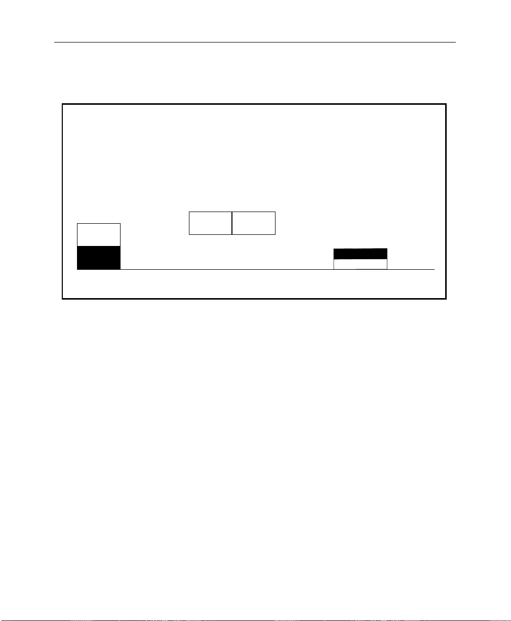
Software Setup
3. Select LOG CHANNEL with the LOG/PHYS ASSIGNMENT button.
MAP INPUTS MENU
config/inputs/map inputs
UNSHAPED
VIDEO
SHAPED
VIDEO
VIDEO/
KEY FMT
XPT BUTTON
NUMBER
(SHIFT-14)
Use the Preset Bus to select button number.
38
XPT BUTTON
NAME
VIDEO INPUT
(DIG SER/RGB/SETUP)
(DIG SER/8 BIT/SETUP/SYNC)
CHROMA KEY INPUT
LOG CHANNEL
PHYS CHANNEL
LOG/PHYS
ASSIGNMENT
NAME XPT
BUTTON >
= 4
KEY INPUT
= 1
= NONE
(INTERNAL)
4. Rotate the VIDEO INPUT knob to assign the desired DPM number
and logical channel for this crosspoint. For example, assign
logical channel 1 of DPM 1 by selecting DPM 1 LOG CHAN 1.
5. Rotate the KEY INPUT knob to assign the desired DPM number
and logical channel for this crosspoint. For example, assign
logical channel 1 of DPM 1 by selecting DPM 1 LOG CHAN 1.
6. Press the top level CONFG button to return to the
Configuration Menu.
Configuring the Peripheral Interface
Use the Peripheral I/F Menu to set the Baud, Parity and
Peripheral Trigger parameters for the switcher peripheral port,
PORT A3, on the Expanded Communication Module.
2-59
Page 92

Section 2— Startup and Configuration
PERIPHERAL INTERFACE MENU
config/extern if/peripheral if
The Peripheral Bus port is labelled
"Port A3" on the rear of the frame
2400
4800
9600
BAUD PARITY
ODD
EVEN19200
NONE38400
NOTE:
electronics.
PERIPHERAL
TRIGGERS>
Select the desired switcher peripheral port BAUD rate
and parity parameters. These should be set the same for
the switcher and the peripheral device. For a DPM-700 set
the baud rate to 38400 and parity to NONE.
Assigning Peripheral Trigger
Use this menu to delegate any of the eight peripheral triggers for
the switcher (designated A thr ough H) to an E-MEM level of MISC,
or DPM 1–DPM 4. Use the LEVEL soft knob to select which E-MEM
level will activate the selected trigger. Each trigger is sent to a
particular address (Device Number) on the Peripheral Bus.
2-60
Once configured, these triggers can be learned into E-MEM effects
(on the MISC level) or fired directly from this menu. Refer to the
Keyframe/Attach Peripheral Trigger Menu description in the
Operation Reference book for attaching peripheral triggers to
E-MEM registers.
Page 93

1. From the Peripheral Interface Menu, press PERIPHERAL
TRIGGERS>
PERIPHERAL TRIGGERS MENU
config/extern if/peripheral if/peripheral triggers
A
B
C
D
E
F
G
H
B
TRIGGER
SELECT
DEVICE NO.
1
1
1
15
0
17
3
FUNCTN NO.
1
4
0
1
2
1
15
to open the Peripheral Triggers Menu.
LEVEL
-
DPM 1
0
-
-
-
-
-
FIRE
B
Software Setup
DEVICE NUMBER
FUNCTION NUMBER
= 1
= 4
<>LEVEL
= DPM 1
2. Increment TRIGGER SELECT to select the designator to be
assigned (A through H).
3. Turn the DEVICE NUMBER soft knob to select the peripheral
device to which that trigger will be sent.
4. Turn the FUNCTION NUMBER to select the device function that
will be triggered by a trigger message on the Peripheral II Bus.
2-61
Page 94

Section 2— Startup and Configuration
The device functions for a DPM–700 depend on whether the DPM
is operating in trigger mode, or E-MEM recall mode, as listed in
Table 2-2.
Table 2-2. DPM 700 Functions
Trigger DPM Trig ger Function DPM E-MEM Recall
0 Function not defined Not valid
1 STOP DPM RECALL REGISTER 1
2 RUN DPM RECALL REGISTER 2
3 NEXT KEYFRAME DPM RECALL REGISTER 3
4 PREVIOUS KEYFRAME DPM RECALL REGISTER 4
5 STOP NEXT DPM RECALL REGISTER 5
2-62
6 REVERSE DPM RECALL REGISTER 6
7 REWIND DPM RECALL REGISTER 7
8 KEYER AUTO-TRANS DPM RECALL REGISTER 8
9 KEYER CUT DPM RECALL REGISTER 9
10 FADE TO BLACK AUTO-TRANS DPM RECALL REGISTER 10
11 FADE TO BLACK CUT DPM RECALL REGISTER 11
12 COMBINER AUTO-TRANS DPM RECALL REGISTER 12
13 COMBINER CUT DPM RECALL REGISTER 13
14 Function not defined DPM RECALL REGISTER 14
15 Function not defined DPM RECALL REGISTER 15
Page 95
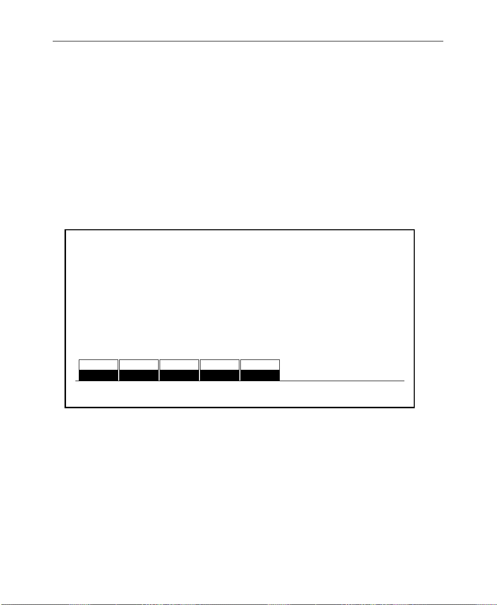
Formatting Aux Buses
There are nine pairs of Aux buses on the Model 2200, designated
A1 through A5, and B1 through B5. Aux pairs one through four
are not configurable (video/key only). Aux buses pair five can be
configured as video/video or video/key signals. In addition, Aux
buses 1-4 (A and B) may be configured for either shaped or
unshaped video output.
1. From the Configuration Menu, press AUX BUS FORMAT> to select
the Aux Bus Format Menu.
AUX BUS FORMAT MENU
config/aux bus format
Software Setup
VIDEO
KEY KEY KEY KEY KEY
AUX
BUS 5B
VIDEO
AUX
BUS 6B
VIDEO
AUX
BUS 7B
VIDEO
AUX
BUS 8B
2. For the “5B” bus to be configured, select either VIDEO or KEY
with the appropriate soft button.
3. Press the AUX BUS SHAPING> Menu button to invoke the Aux Bus
Shaping Menu.
VIDEO
AUX
BUS 9B
AUX BUS
SHAPING >
2-63
Page 96

Section 2— Startup and Configuration
The Aux Bus Shaping Menu allows you to select the output
configuration to be always shaped or always unshaped on aux buses
1-4. Thus the configuration should be set according to the input
needs of the external device connected to the aux bus. The
switcher then internally decides whether to turn on shaping or
unshaping circuitry according to the nature of the video/key pair
feeding the aux bus.
NOTE:
only to the Aux 1 through Aux 4 outputs and only if the Effects Send
option is present. Without the circuitry on the Effects Send module, the
aux bus outputs simply pass whatever signal is present—either shaped
or unshaped.
1. Press the PHYS AUX SELECT button to select the physical aux bus
2. Set the VIDEO/KEY FMT selections for Aux Buses 1 through 4 to
The LOGICAL column indicates the logical aux bus being used. This
may be different from the physical aux bus when the Model 2200
is connected to a Kaleidoscope or other DPM that is able to control
the aux buses. (This column is informational only. You can not
change it from this menu.)
The output shaped/unshaped selections for the Aux Buses apply
to be used in the effects send loop.
match the characteristic SHAPED or UNSHAPED expected by the
external devices connected to those outputs. These settings
control the states of the shapers and unshapers on the Aux Bus
outputs.
2-64
Page 97

AUX BUS SHAPING MENU
config / aux bus format / aux bus shaping
LOGICALPHYSICAL
AUX BUS 1 ONAUX BUS 1
AUX BUS 2
AUX BUS 3
AUX BUS 4
AUX BUS 1
PHYS AUX
SELECT UNSHAPER
AUX BUS 2
AUX BUS 3
AUX BUS 4
OFF
OFF
OFF
ON
OFF
Software Setup
NOTE:
Since the process of unshaping the video signal results in
dividing the video signal by its key, level errors, especially ar ound black,
may produce extreme signal levels where the key is at or near zero.
Kaleidoscope ignores these extraneous signals, but they may cause
problems with external sync separators or clamps. Therefore, it is
recommended that connections to Kaleidoscope inputs be made directly
from the 2200 Aux Bus outputs.
When the Effects Send option is not present, the VIDEO/KEY FMT
selections are not visible in the menu.
2-65
Page 98

Section 2— Startup and Configuration
2-66
Page 99

3
Switcher Concepts
This section describes a few basic concepts that you should know
before you operate your switcher. You might be tempted to skip
over this section, especially if you are an experienced switcher
operator . Nevertheless, we suggest that you to br owse it anyway,
because it explains operating concepts that help you more fully
understand how the switcher works.
Items discussed in this section include the following:
■ Clear Working Buffer on page 3-2
■ Auto Delegation on page 3-4
■ Crosspoint Bus on page 3-5
■ Transitions on page 3-6
■ Keys on page 3-9
■ Shaped and Unshaped Video on page 3-12
■ Super Black on page 3-14
■ Chroma Key on page 3-15
■ Coring on page 3-16
■ Layering on page 3-17
■ E-MEM Effects Memory on page 3-18
■ Keyframing / Timelines / Effects Editing on page 3-21
■ Effects Send (Option) on page 3-23
■ Frame Store (Option) on page 3-24
■ Mask Store (Option) on page 3-25
3-1
Page 100

Section 3 — Switcher Concepts
Clear Working Buffer
The Current Working Buffer (CWB) is an area of system memory
that stores the current switcher state. That is, it tracks the settings
of switch and variable control functions on the control panel, as
well as those of many switch and control functions set in the
menus.
When an E-MEM recall is done, the data in the recalled E-MEM
Register is loaded into the Current Working Buffer, which sets the
switcher parameters of all enabled levels to match those stored in
the first keyframe of an E-MEM effect.
The GVP Factory Default of the CWB is a set of switcher
parameters stored in memory that may be used to return the
switcher to a known set of conditions. Some of these parameters
may be periodically updated with software updates.
The User-Defined Default buffer is battery-backed RAM that may
be used to store a set of parameters tailored to your requir ements
and preferences. At power-up the information in the UserDefined Default memory is loaded into the Current Working
Buffer, which sets the initial state of the switcher.
3-2
At any time, the User-Defined Default values may be restored to
all enabled areas of the switcher by pressing the CLEAR WORK
BUFR
button on the E-MEM Subpanel.
The data in the User-Defined Default Buffer may also be modified
at any time through the Configuration/User Prefs/Define
Defaults Menu.
 Loading...