


Model 2182A
Nanovoltmeter
Quick Start Guide

Safety precautions
The following safety precautions should be observed before using this product and
any associated instrumentation. Although some instruments and accessories would
normally be used with nonhazardous voltages, there are situations where hazardous
conditions may be present.
This product is intended for use by personnel who recognize shock hazards and are
familiar with the safety precautions required to avoid possible injury. Read and follow
all installation, operation, and maintenance information carefully before using the
product. Refer to the user documentation for complete product specifications.
If the product is used in a manner not specified, the protection provided by the
product warranty may be impaired.
The types of product users are:
Responsible body is the individual or group responsible for the use and maintenance of equipment, for ensuring that the equipment is operated within its specifications and operating limits, and for ensuring that operators are adequately trained.
Operators use the product for its intended function. They must be trained in electrical
safety procedures and proper use of the instrument. They must be protected from
electric shock and contact with hazardous live circuits.
Maintenance personnel perform routine procedures on the product to keep it
operating properly, for example, setting the line voltage or replacing consumable
materials. Maintenance procedures are described in the user documentation. The
procedures explicitly state if the operator may perform them. Otherwise, they should
be performed only by service personnel.
Service personnel are trained to work on live circuits, perform safe installations, and
repair products. Only properly trained service personnel may perform installation and
service procedures.
Keithley products are designed for use with electrical signals that are measurement,
control, and data I/O connections, with low transient overvoltages, and must not be
directly connected to mains voltage or to voltage sources with high transient
overvoltages. Measurement Category II (as referenced in IEC 60664) connections
require protection for high transient overvoltages often associated with local AC mains
connections. Certain Keithley measuring instruments may be connected to mains.
These instruments will be marked as category II or higher.
Unless explicitly allowed in the specifications, operating manual, and instrument
labels, do not connect any instrument to mains.
Exercise extreme caution when a shock hazard is present. Lethal voltage may be
present on cable connector jacks or test fixtures. The American National Standards
Institute (ANSI) states that a shock hazard exists when voltage levels greater than
30 V RMS, 42.4 V peak, or 60 VDC are present. A good safety practice is to expect
that hazardous voltage is present in any unknown circuit before measuring.
Operators of this product must be protected from electric shock at all times. The
responsible body must ensure that operators are prevented access and/or insulated
from every connection point. In some cases, connections must be exposed to
potential human contact. Product operators in these circumstances must be trained to
protect themselves from the risk of electric shock. If the circuit is capable of operating
at or above 1000 V, no conductive part of the circuit may be exposed.
Do not connect switching cards directly to unlimited power circuits. They are intended
to be used with impedance-limited sources. NEVER connect switching cards directly
to AC mains. When connecting sources to switching cards, install protective devices
to limit fault current and voltage to the card.
Before operating an instrument, ensure that the line cord is connected to a
properly-grounded power receptacle. Inspect the connecting cables, test leads, and
jumpers for possible wear, cracks, or breaks before each use.
When installing equipment where access to the main power cord is restricted, such as
rack mounting, a separate main input power disconnect device must be provided in
close proximity to the equipment and within easy reach of the operator.
For maximum safety, do not touch the product, test cables, or any other instruments
while power is applied to the circuit under test. ALWAYS remove power from the
entire test system and discharge any capacitors before connecting or disconnecting
cables or jumpers, installing or removing switching cards, or making internal changes,
such as installing or removing jumpers.

Do not touch any object that could provide a current path to the common side of the
circuit under test or power line (earth) ground. Always make measurements with dry
hands while standing on a dry, insulated surface capable of withstanding the voltage
being measured.
When fuses are used in a product, replace with the same type and rating for
continued protection against fire hazard.
For safety, instruments and accessories must be used in accordance with the
operating instructions. If the instruments or accessories are used in a manner not
specified in the operating instructions, the protection provided by the equipment may
be impaired.
Do not exceed the maximum signal levels of the instruments and accessories.
Maximum signal levels are defined in the specifications and operating information and
shown on the instrument panels, test fixture panels, and switching cards.
Chassis connections must only be used as shield connections for measuring circuits,
NOT as protective earth (safety ground) connections.
If you are using a test fixture, keep the lid closed while power is applied to the device
under test. Safe operation requires the use of a lid interlock.
If a screw is present, connect it to protective earth (safety ground) using the wire
recommended in the user documentation.
The symbol on an instrument means caution, risk of hazard. The user must refer
to the operating instructions located in the user documentation in all cases where the
symbol is marked on the instrument.
The symbol on an instrument means warning, risk of electric shock. Use standard
safety precautions to avoid personal contact with these voltages.
The symbol on an instrument shows that the surface may be hot. Avoid personal
contact to prevent burns.
The symbol indicates a connection terminal to the equipment frame.
If this symbol is on a product, it indicates that mercury is present in the display
lamp. Please note that the lamp must be properly disposed of according to federal,
state, and local laws.
The WARNING heading in the user documentation explains hazards that might result
in personal injury or death. Always read the associated information very carefully
before performing the indicated procedure.
The CAUTION heading in the user documentation explains hazards that could
damage the instrument. Such damage may invalidate the warranty.
The CAUTION heading with the symbol in the user documentation explains
hazards that could result in moderate or minor injury or damage the instrument.
Always read the associated information very carefully before performing the indicated
procedure. Damage to the instrument may invalidate the warranty.
Instrumentation and accessories shall not be connected to humans.
Before performing any maintenance, disconnect the line cord and all test cables.
To maintain protection from electric shock and fire, replacement components in mains
circuits — including the power transformer, test leads, and input jacks — must be
purchased from Keithley. Standard fuses with applicable national safety approvals
may be used if the rating and type are the same. The detachable mains power cord
provided with the instrument may only be replaced with a similarly rated power cord.
Other components that are not safety-related may be purchased from other suppliers
as long as they are equivalent to the original component (note that selected parts
should be purchased only through Keithley to maintain accuracy and functionality of
the product). If you are unsure about the applicability of a replacement component,
call a Keithley office for information.
Unless otherwise noted in product-specific literature, Keithley instruments are
designed to operate indoors only, in the following environment: Altitude at or below
2,000 m (6,562 ft); temperature 0 °C to 50 °C (32 °F to 122 °F); and pollution degree
1 or 2.
To clean an instrument, use a cloth dampened with deionized water or mild,
water-based cleaner. Clean the exterior of the instrument only. Do not apply cleaner
directly to the instrument or allow liquids to enter or spill on the instrument. Products
that consist of a circuit board with no case or chassis (e.g., a data acquisition board
for installation into a computer) should never require cleaning if handled according to
instructions. If the board becomes contaminated and operation is affected, the board
should be returned to the factory for proper cleaning/servicing.
Safety precautions as of June 2018.
Safety
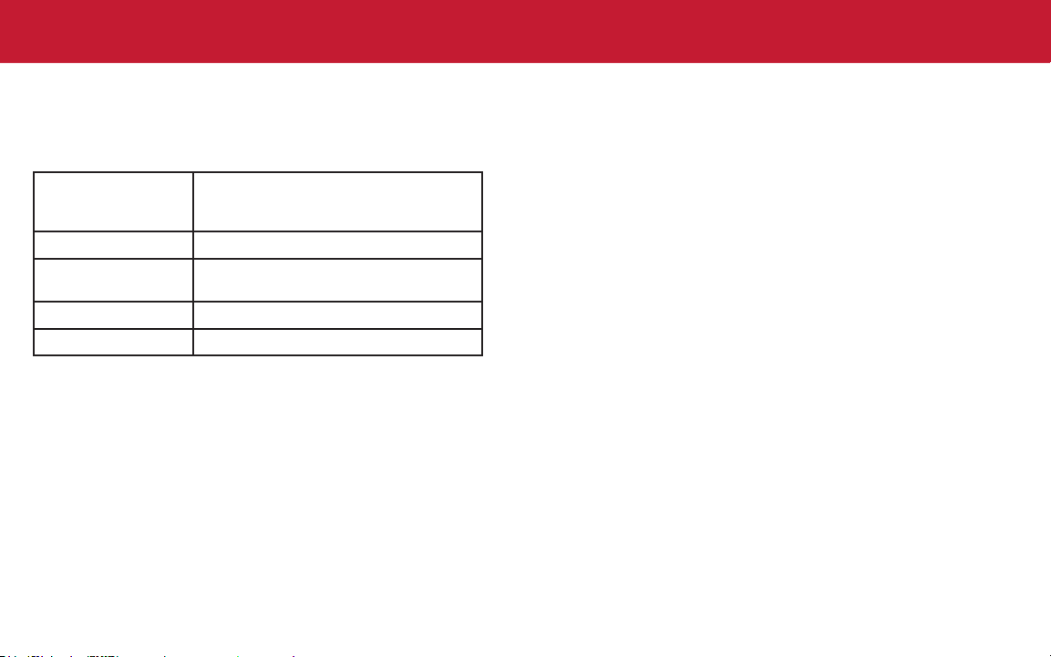
Power and environmental ratings
For indoor use only.
Power supply
Power consumption
Operating
environment
Storage temperature
Pollution degree
100 V ac /120 V ac / 220 V ac / 240 V ac
50 Hz, 60 Hz, and 400 Hz, automatically
sensed at power-up
22 VA
Specied for 0 °C to 50 °C; specied to 80%
relative humidity at 35 °C
−40 °C to 70 °C
1 or 2

Introduction
The two-channel Model 2182A Nanovoltmeter is optimized
for making stable, low noise voltage measurements and for
characterizing low resistance materials and devices reliably
and repeatably. It provides higher measurement speed and
signicantly better noise performance than alternative low
voltage measurement solutions.
The 2182A oers a simplied delta mode for making
resistance measurements when used in combination with a
reversing current source, such as the Model 6220 or 6221.
Complete documentation for the 2182A instrument is
available for download on the Keithley web page at
tek.com/en/products/keithley.
The 2182A documentation includes:
• Quick Start Guide: This document. It provides unpacking
instructions, describes basic connections, and reviews
basic operation information.
• User’s Manual: Includes installation, instrument
description, operation, and maintenance information.
• Service Manual: Provides performance
verication, calibration, routine maintenance, and
troubleshooting information.
• Information on accessories.
Measurement capabilities
• Two voltage measurement channels.
• Measure voltage from 1 nV to 100 V (channel 1);
10 nV to 12 V (channel 2).
• Temperature measurements
• Ratio, delta, mx + b, and percent math operations.
Introduction

Unpack and inspect the instrument
To unpack and inspect the instrument:
1. Inspect the box for damage.
2. Open the top of the box.
3. Remove the documentation and accessories.
4. Carefully lift the instrument out of the box.
5. Inspect the instrument for any obvious signs of
physical damage. Report any damage to the shipping
agent immediately.
6. There may be a protective lm over the display lens,
which can be removed.
You receive the 2182A with these accessories
and documents:
• Power line cord
• DeoxIT
®
Contact Cleaner
• Model 2107-4 Low-thermal Input Cable Assembly
• Model 2182-KIT Low-thermal Connector with Strain Relief
• Four copper alligator clips that attach to the copper lugs
of the cable assembly
• Software and documentation downloads information
• Safety precautions
• Model 2182A Nanovoltmeter Quick Start Guide
(this document)

Connect the instrument
Important test system safety information
This product is sold as a stand-alone instrument that may
become part of a system that could contain hazardous
voltages and energy sources. It is the responsibility of the
test system designer, integrator, installer, maintenance
personnel, and service personnel to make sure the system is
safe during use and is operating properly.
You must also realize that in many test systems a single
fault, such as a software error, may output hazardous signal
levels even when the system indicates that there is no
hazard present.
It is important that you consider the following factors in your
system design and use:
• The international safety standard IEC 61010-1 denes
voltages as hazardous if they exceed 30 V
42.4 V
locations. Keithley Instruments products are only rated for
dry locations.
• Read and comply with the specications of all instruments
in the system. The overall allowed signal levels may be
constrained by the lowest rated instrument in the system.
For example, if you are using a 500 V power supply with
a 300 V dc rated switch, the maximum allowed voltage in
the system is 300 V dc.
or 60 V dc for equipment rated for dry
PEAK
RMS
and
• Cover the device under test (DUT) to protect the operator
from ying debris in the event of a system or DUT failure.
• Make sure any test xture connected to the system
protects the operator from contact with hazardous
voltages, hot surfaces, and sharp objects. Use
shields, barriers, insulation, and safety interlocks to
accomplish this.
• Double-insulate all electrical connections that an operator
can touch. Double insulation ensures the operator is
still protected even if one insulation layer fails. Refer to
IEC 61010-1 for specic requirements.
• Make sure all connections are behind a locked cabinet
door or other barrier. This protects the system operator
from accidentally removing a connection by hand and
exposing hazardous voltages. Use high-reliability fail-safe
interlock switches to disconnect power sources when a
test xture cover is opened.
• Where possible, use automatic handlers so that operators
are not required to access the DUT or other potentially
hazardous areas.
• Provide training to all users of the system so that they
understand all potential hazards and know how to protect
themselves from injury.
• In many systems, during power up, the outputs may be in
an unknown state until they are properly initialized. Make
sure the design can tolerate this situation without causing
operator injury or hardware damage.
Unpack

NOTE
To keep users safe, always read and follow all safety warnings
WARNING
provided with each of the instruments in your system.
Install the instrument
Connect line power
The 2182A operates from a line voltage of 100 V ac,
120 V ac, 220 V ac, or 240 V ac at line frequencies of 45 Hz
to 66 Hz or 360 Hz to 440 Hz. It automatically senses line
frequency. Make sure the operating voltage in your area
is compatible.
You can use the 2182A on a bench or in a rack. See the
instructions that came with your rack-mount kit if you are
installing the 2182A in a rack.
To prevent damaging heat build-up and ensure specied
performance, make sure there is adequate ventilation and
airow around the instrument to ensure proper cooling. Do
not cover the ventilation holes on the top, sides, or bottom of
the instrument.
Position the instrument so that it is easy to reach any
disconnecting devices, such as the power cord and the
power switch.
The power cord supplied with the 2182A contains a
separate protective earth (safety ground) wire for use
with grounded outlets. When proper connections are
made, the instrument chassis is connected to power‑line
ground through the ground wire in the power cord. In
the event of a failure, not using a properly grounded
protective earth and grounded outlet may result in
personal injury or death due to electric shock.
Do not replace detachable mains supply cords with
inadequately rated cords. Failure to use properly rated
cords may result in personal injury or death due to
electric shock.

CAUTION
Operating the instrument on an incorrect line voltage
may cause damage to the instrument, possibly voiding
the warranty.
To connect line power:
1. Make sure the front-panel power switch is in the
o (O) position.
2. Connect the socket of the supplied power cord to the
power module on the rear panel.
3. Connect the plug of the power cord to a grounded
ac outlet.
Turn on the instrument
1. Disconnect any devices under test (DUTs) from
the 2182A.
2. Turn on the instrument by pressing the front-panel
POWER switch to the on (|) position.
You must turn on the 2182A and allow it to warm up for at
least 2½ hours to achieve rated accuracies.
Power‑up sequence
On power up, the 2182A performs self-tests and momentarily
lights all digit segments and annunciators. If a failure is
detected, the instrument momentarily displays an error
message and the ERR annunciator turns on.
When the instrument passes the self-tests, the rmware
revision levels are displayed. For example:
REV: A01 A02
Where A01 is the main board ROM revision and A02 is the
display board ROM revision.
After the power-up sequence, the instrument begins to
display readings.
Connect

Connections for testing
WARNING
CAUTION
To prevent electric shock, test connections must be
congured such that the user cannot come in contact
with test leads or any device under test (DUT) that is
in contact with the conductors. It is good practice to
disconnect DUTs from the instrument before powering
the instrument. Safe installation requires proper shields,
barriers, and grounding to prevent contact with test leads.
A hazardous voltage condition exists at or above 42 V
To prevent electric shock that could result in personal
injury or death, never make or break connections while
hazardous voltage is present.
PEAK
Exceeding the following limits may cause instrument
damage that will void the warranty.
Channel 1 HI and LO inputs have a maximum
measurement capability of 120 V
are protected to 150 V
to any terminal or 350 V
PEAK
. These inputs
PEAK
to chassis.
Channel 2 HI and LO inputs have a maximum
measurement capability of 12 V
protected to 150 V
protected to 70 V
.
protected to 350 V
PEAK
PEAK
PEAK
to any terminal. Channel 2 LO is
to Channel 1 LO. Both inputs are
to chassis.
. Channel 2 HI is
PEAK
PEAK
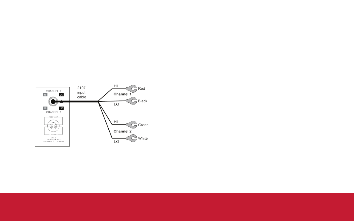
Model 2107 low‑thermal input cable
The 2107, shown in the following gure, is terminated with
a CHANNEL connector on one end and copper lugs on the
other end. The cable is shielded to chassis ground when
connected to the 2182A. You can use this cable to make
voltage measurements and temperature measurements that
use an external simulated reference junction.
To make voltage connections, clamp the cleaned copper
lugs of the cable to the cleaned copper connectors of the
test circuit. For the test circuit, use clean #10 copper bus
wire wherever possible. Clean copper-to-copper connections
minimize thermal electromagnetic elds (EMFs). EMFs can
corrupt a measurement.
Connect

Voltage measurement connections
You can perform single or dual channel voltage
measurements. The dual channel feature of the 2182A
allows you to make comparison measurements in a
test circuit.
The following gure shows typical connections to measure a
DUT using a single channel.
The following gure shows typical connections to make
comparison measurements of two devices in a test circuit.
For this measurement conguration, there is no voltage
dierential between the two measurement channels.
Channel 2 HI is connected directly to Channel 1 LO.

Temperature measurement connections
You can use Channel 1 of the 2182A to make temperature
measurements. The following gure shows connections
using the internal reference junction. The thermocouple wires
must be soldered directly to the CHANNEL connector.
The following gure shows temperature-only connections
using an ice bath as a simulated reference junction. The
connection points for the input cable and the thermocouple
wires are immersed in the ice bath.
Connect

Basic operation
Make a voltage measurement
Most front panel keys have two functions. The name on the
key indicates its primary function. The name in blue above a
key indicates its function when the SHIFT key is pressed.
For example, press DCV1 to select the Channel 1 voltage
measurement function. Press SHIFT then MX+B to choose
the mx + b function.
The following test veries basic operation of the 2182A. In
this test, you use the front-panel controls to make a voltage
measurement.
To measure voltage:
1. Make connections to the DUT as described in “Voltage
measurement connections.”
2. Press DCV1, which measures voltage on channel 1.
3. Press AUTO RANGE to enable automatic range setting.
4. Observe the voltage reading on the front panel.

Make a temperature measurement
NOTE
In this test, you use the front-panel controls to make a
temperature measurement.
To measure voltage:
1. Make connections to the DUT as described in
“Temperature measurement connections.”
2. Press SHIFT then TCOUP.
3. Select UNITS to set the temperature units (°C, °F, or K).
4. Select SENS and select TCOUPLE.
5. Select TYPE and select the thermocouple type that you
are using to measure temperature.
6. Select JUNC and select the type of reference
measurement:
• To reference measurements to the internal reference
junction: Select INTRNL.
• To reference measurements to an external simulated
reference: Select SIM. You are prompted to enter the
simulated reference temperature. Use the arrow keys
to display the value and press ENTER.
7. Select TEMP 1 to measure temperature on channel 1.
8. Observe the temperature reading on the front panel.
These steps conrm basic functionality of your instrument.
Test

Measurement considerations
FAQs
For sensitive measurements, follow these guidelines to
maximize measurement accuracy:
• Use only clean, copper-to-copper connections to minimize
thermal EMFs.
• Any solder connections should use silver solder to minimize
thermal EMFs.
• Clean all connector terminals of oxidation using a small
amount of DeoxIT.
• Use the relative oset (REL) to null out osets:
• Connect the circuit, but leave the source disconnected.
• Select DCV1 or DCV2 as appropriate.
• Press REL to null osets.
• Repeat for other channel if needed.
• Connect the source, and make the measurement.
• Keep the 2182A and test circuit away from electrical noise
sources, and shield if necessary.
Refer to the Model 2182A Nanovoltmeter User’s Guide for
additional information.
Where can I nd updated drivers or rmware?
For the latest drivers and additional support information, see
the Keithley Instruments support website.
To nd drivers that are available for your instrument:
1. Go to tek.com/en/support/product-support.
2. Enter 2182A and select GO.
3. Select Software.

Next steps
For more information, refer to the Keithley Instruments
website, tek.com/en/products/keithley.
You can nd support and additional information about
the instrument in the Model 2182A Nanovoltmeter User’s
Manual.
FAQs and next steps

Contact information: 1-800-833-9200
For additional contacts, see https://www.tek.com/en/contact-tek
Find more valuable resources at TEK.COM.
Copyright © 2022, Tektronix. All rights reserved.
Tektronix products are covered by U.S. and
foreign patents, issued and pending. Information
in this publication supersedes that in all previously
published material. Specification and price change
privileges reserved. TEKTRONIX and TEK are
registered trademarks of Tektronix, Inc. All other
trade names referenced are the service marks,
trademarks, or registered trademarks of their
respective companies.
2182A-903-01 Rev. B July 2022
*P2182A-903-01B*
 Loading...