

Page 1

INSTKUCTIW MANUAL
IlUUEL 1YZU
TKWS UPTIUII
Copyright 1981 Keithley Instruments, Inc.
First Printing, July, 1981, Cleveland, Ohio, U.S.A.
Document No. 32000, Kev. A
Page 2

Page 3
Table of Contents
Section
ClENEKAL INFORMATION
1.
l-l.
l-3. Warranty Information.
1-5.
l-7. Safety Symbols and Terms.
l-9. Specifications.
2.
OPERATING INSTRUCTIONS.
2-l.
2-4. Operation in Model 192.
3.
MAINTENANCE .................................
3-2. Installation in Model 191
3-3. Installation in Model 192
3-4.
3-6. Kecommended Test Equipment.
3-7.
3-9.
3-11.
3-13. Calibration
3-15. Kecommended Test Equipment.
3-17. Environmental Conditions.
X-19.
3-22. Troubleshooting
3-24. Troubleshootiny Procedure
Introduction.
Manual Addendums.
Operation in Model 191.
Performance Verification.
Environmental Conditions.
Performance Verification Procedure.
Initial Conditions.
Calibration Procedure
.............................
.............................
............................
..............................
.........................
...........................
.......................
...........................
........................
........................
.......................
.......................
.......................
.......................
..........................
.......................
.........................
............................
.......................
......................
..................
......................
Page
l-l
l-l
l-l
l-l
l-l
l-l
2-1
2-l
2-1
3-l
3-l
3-2
3-3
3-3
3-3
3-3
3-4
3-6
3-6
3-G
3-6
3-9
3-9
4.
TtiEURY OF UPEKATIUN
REPLACEABLE PAKTS
5.
5-l.
5-3. Ordering Information.
5-5.
5-7.
General
Factory Service
Schematic and Component Layout.
................................
.............................
..............................
.........................
............................
....................
4-l
5-l
5-l
5-l
5-i
5-l
Page 4

Page 5
Model 1920
l-l. INTRODUCTION
General Information
SECTION 1. GENERAL INFORMATION
l-2.
Models
siynal.
Model
installable.
1-3.
l-4.
to exercise the Warranty,
the proper action to be taken.
facilities in the United States, West tiermany,
Switzerland and Austria.
your instrument may be directed to the applications engineer at any of the above
locations.
l-5. Manual Addendums
1-G.
will be explained on an addendum which will be attached to the inside back cover.
The Keithley Model
192
and
191.
When the 1920 is installed in the Model
1920
has four ranges on which an AC siynal can be measured.
Warranty Information
The warranty is yiven on the inside front cover of this manual. If there is a need
Check the inside front cover of this manual for addresses.
Improvements or changes to the instrument that occur after printing of the [manual
1920
is a True Root Mean Square (TKMS) AC plug-in option for the
The 1920 enables the 191 or 192 to measure the TKMS value of an AC
192
an ACtUC function is available. The
It
is field
contact the Keithley Representative in your area to determine
Keithley maintains complete repair and calibration
tireat Britain, France, the Netherlands,
Information concerning the application, operation or service of
1-7.
l-8. The symbol
instructions.
The symbol
The WARNING used in this manual explains dangers that could result in personal injury
or death.
The CAUTION used in this manual explains hazards that could damage the instrument.
l-9.
l-10.
Safety Symbols and Terms
A
on the instrument denotes that the user should refer to the operating
t
Specifications
Uetailed specifications for the Model 1920 are given in Table
on the instrument denotes that up to 5UllV may be present on the terminals.
l-l.
l-l
Page 6
General Information
Model 1920
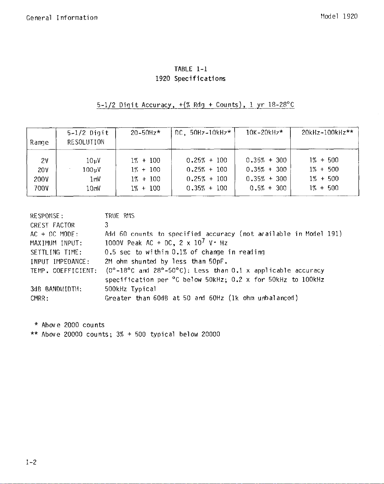
TABLE 1-l
1920 Specifications
5-l/2 Digit Accuracy, +(% Rdg + Counts),
5-l/2 Digit
Range
2v 1OPV 1% t
2ov lOOld
2oov 1mV 1% t
7oov 1OmV
RESPONSE:
CREST FACTOR
AC + DC MODE:
riAxIriuri INPUT:
SETTLING TIME:
INPUT IMPEDANCE:
TEMP. COEFFICIENT:
3dB BANTMIDTH:
CFIRR:
RESOLUTION
TRUE RFlS
Add 60 counts to specified accuracy (not wailable in We1
1OOOV Peak AC + DC, 2 x lo7 V* Hz
0.5 set to within 0.1% of change in reading
211 ohm shunted by less than 5OpF.
(O"-18OC and 28"-5O'C): Less than
specification per "C below 50kHz; 0.2 x for 50kHz to 1OOkHz
500kHz Typical
Greater than 60dB at 50 and 60Hz
20-50Hz"
1% t 100
1% t 100
100
100
1
yr 18-28'C
DC, 50Hz-lOkHz* lOK-20kHz"
0.25% t 100 0.35% + 300
0.25% t 100 0.35% + 300
0.25% + 100 0.35% + 300 1% t 500
0.354: t 100 0.5% + 300
0.1
x applicable accuracy
(lk
ohm unbalanced)
20kHz-lOOkHz**
1% t 500
1% t 500
1% t 500
191)
* Above 2000 counts
** Above 20000 counts; 3% + 500 typical below 20000
l-2
Page 7
Model 1920
Operating Instructions
SECTION 2. OPERATING INSTRUCTIONS
Z-l. Operating Instructions for the rlcdel 1920 installed in the ilodel 191 are as
follows:
2-2.
to 1000v.
voltage.
2-3.
Ilith the ilodel 1920 option, the ilcdel 191
The instrument displays the True Koot llean Square (TKilS) value of an AC
It has a frequency response of 20Hz to 100ktlz.
The rnaximm reading is 199YYY. Werrange is irdicatcd by (-) l-----, except on
the 1000 volt range.
The 700 volt range is selected idith the 1000 volt button. On the
reads AC voltages froln 10 r;licrovolts/digit
700 volt range, the display can read beyond the rnaxiinuln allobiable input voltage. ilaximun
allobcable input: 1OOOV Peak AC + DC; 2 x lo7 V'Hz. Use the ilodel 191 to lneasure AC
voltage as follobis:
CAUTION
Do not exceed maximum allohcable input voltage. Instrument damage may
occur.
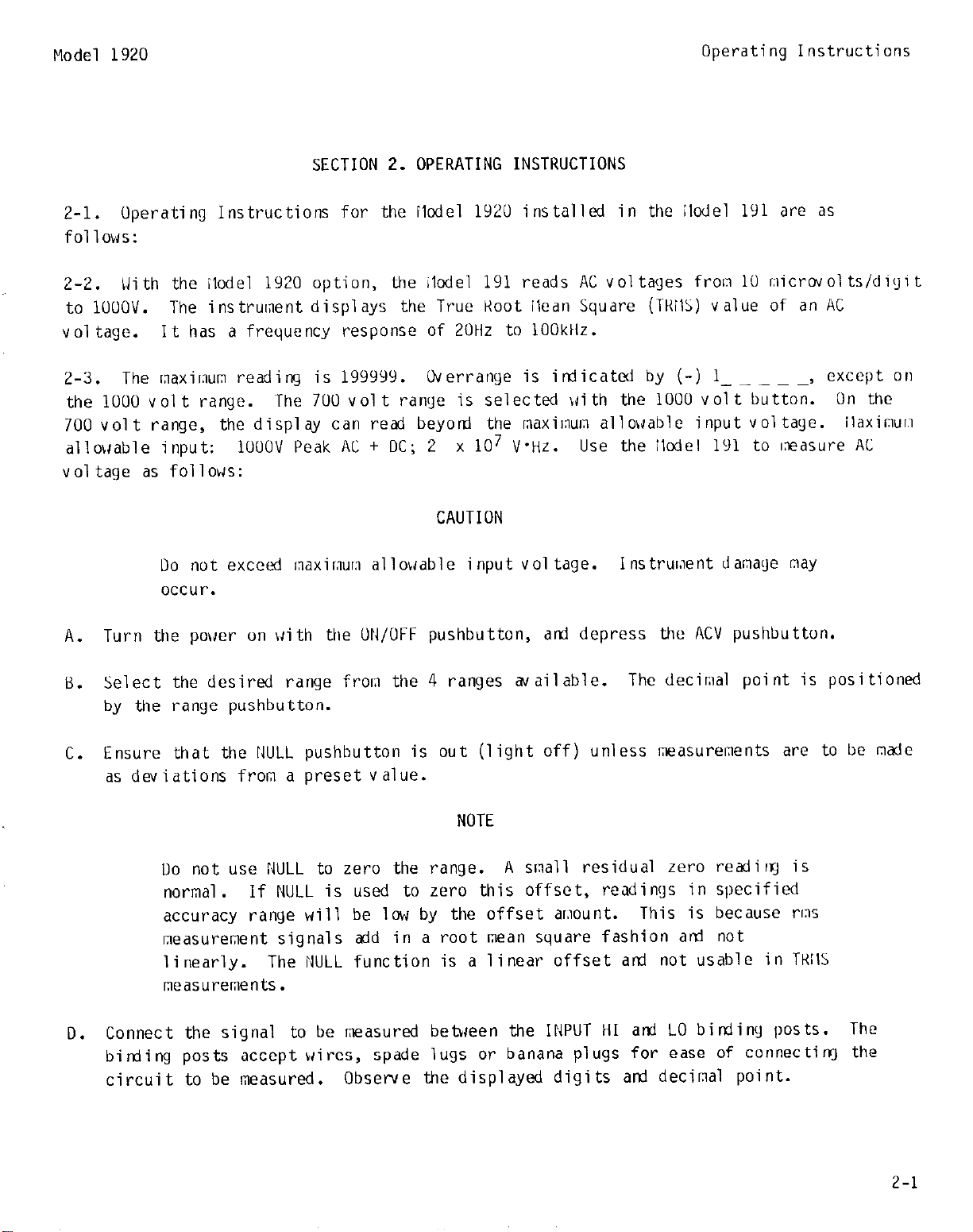
A. Turn the pokier on IJith the UN/OFF pushbutton,
Select the desired range from the 4 ranges available.
8.
ati depress the ACV pushbutton.
The decimal point is positioned
by the range pushbutton.
Ensure that the I0JLL pushbutton is out (light off) unless measurements are to be made
C.
as deviations from a preset value.
NOTE
Do not use NULL to zero the range.
A small residual zero readirq is
normal. If NULL is used to zero this offset, readings in specified
accuracy range will be low by the offset amount.
This is because rms
measurement signals add in a root mean square fashion arrl not
linearly.
The NULL function is a linear offset axl not usable in TKllS
measurements.
Connect the signal to be measured between the INPUT HI ati LO binjiny posts. The
0.
birding posts accept wires, spade lugs or banana plugs for ease of connectiq the
circuit to be measured.
Observe the displayed digits ard decimal point.
2-1
Page 8

Operating Instructions
E.
For specified accuracy (pulse widths ,lOns, peak voltage (1.5 x full scale) Figure 2-1
shows the allowable input signal vs. crest factor.
crest factor of three the displayed reading must be less than 100,000 counts (1V on
the 2V range).
crest factors exceeding that shown in Figure2-I, but accuracy will slowly degrade (For
CF >3 but<10 typical accuracy is degraded by (CF-3) x 0.36% arti peak signal must be
less than 5 x full scale for that range).
So long as the maximum input is not exceeded no damage will result in
CF
The figure illustrates that for a
Model 1920
I
0
Displayed Counts
Figure 2-l.
2-4. Operating Instructions for the Model lY20 installed in the Model 192 are as
follows:
2-5.
to 1ooov.
signal.
2-G.
input is 1OOOV Peak AC f DC; 2 x 10⁷V.Hz. Use the Model
voltages as follows:
With the Model 1920 option, the Model
The instrument displays the True Koot Mean Square (TKMS) value of an AC voltage
The maximum reading is 199999.
Do not exceed maximum allowable input voltage. Instrument darnage may
occur.
Crest Factor VS. Displayed Counts
100000
192
reads AC voltages from 1 microvolt/digit
Overrange is indicated by OFLO. Maximum allowable
CAUTION
I
200000
192
to measure AC or AC + DC
A. TURN POWER UN with UN/OFF pushbutton.
B.
Press the ACV button once to select the ACV (TKMS) function. Press the ACV button
ayain and the 192 will measure the T'KMS value of an AC + UC signal (AC signal
superimposed with a DC level). The ACV and DCV LEDs will light simultaneously when
the AC + UC function is enabled.
the ACV function. Pressiny the DC button while in AC t DC returns the
function.
Pressing the ACV button again will return the 192 to
192
the DCV
2-2
Page 9

UPEKATINti INSTKUCTIUNS
IWDEL 1YZU
NOTE
The 14odel 192 will display "NO AC" if ACV is selected without the 1920
or 1910 ACV option.
The AC + UC function is available only with C-4
and dbove software and Kev U and above Analoy Board.
C. SELECT KANtiE from the four ranyes available. The decimal point is positioned by the
ranye pushbutton. The 1UOUV ranye is selected with the 2000 button. If the ZUIQ
button is inadvertently pressed when in ACV function,
the 192 will set the ranye to
1uuo.
Il. ZEKU OFF unless [measurements are to be made as deviations frown a preset value.
NOTE
Uo not use ZEKU to zero the ranye. A small residual zero readiny is
normal. If LEKU is used, the residual voltaye readiny in specified
accuracy ranye will be low by the amplitude of the zeroed residual
voltaye.
This is because rms measurement signals add in a root mean
square fashion and NUT linearly. THe LEKU function is a linear offset
and not usable in TKMS measurelnents.
CONNECT IllPUT to be measured between the HI HCV and LO bindiny posts.
E.
F.
TAKE KEAUING.
ti. For specified accuracy (pulse widths LlUus, peak voltage (1.5 x full scale) Figure Z-l
shows the allowable input siynal vs. crest factor.
The figure illustrates that for d
crest factor of three the displayed readiny (must be less than lUU,UUU counts (1V on
the ZV ranye).
crest factors exceediny that shown in Fiyure 2-1,
So long as the maximum input is not exceeded no damage will result in
but accuracy will slowly degrade
(For CF >3 but 510 typical accuracy is degraded by (CF-3) x U.3GX and peak signal must
be less than 5 x full scale for that range).
Page 10

Page 11
Model 1920
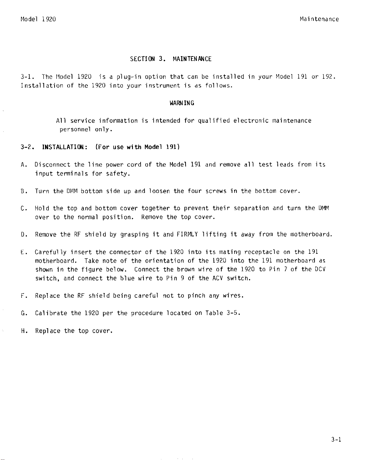
SECTION 3. MAINTENANCE
3-l. The Model 1920 is a plug-in option that can be installed in your Model 191 or 192
Instdllation of the 1920 into your instrument is as follows.
WARNING
All service information is intended for qualified electronic maintenance
personnel only.
Maintenance
3-2. INSTALLATION: (For use with Model
A. Disconnect the line power cord of the Model
input terminals for safety.
B. Turn the DMM bottom side up and loosen the four screws in the bottom cover.
Hold the top and bottom cover together to prevent their separation and turn the DMM
C.
over to the normal position. Remove the top cover.
D. Remove the RF shield by grasping it and FIRMLY lifting it away from the motherboard.
E. Carefully insert the connector of the
motherboard. Take note of the orientation of the
shown in the figure below. Connect the brown wire of the
switch, and connect the blue wire to Pin 9 of the ACV switch.
F. Replace the RF shield being careful not to pinch any wires.
G. Calibrate the
1920
per the procedure located on Table 3-5.
191)
1920
191
and remove all test leads from its
into its mating receptacle on the 191
1920
into the 191 motherboard as
1920
to Pin 7 of the DCV
Replace the top cover.
H.
3-l
Page 12

Maintenance
Model 1920
NOTE
Pin locations for the switches are shown on the decal on top of the RF
shield.
WARNING
All service information is intended for qualified electronic
maintenance personnel only.
3-3.
INSTALLATION: (For use with Model 192)
A. Uisconnect the line power cord of the Model 192 and remove all test leads from its
input terminals for safety.
B.
Remove two screws that hold the top cover to the rear panel and remove the cover.
C.
Remove the top shield from the Analog Board by grasping it and FIRMLY lifting it off,
with a prying motion of the four retaining clips.
u. Carefully insert the connector of the 1920 into its mating receptacle on the Analog
Uoard.
Take note of the orientation of the 1920 onto the 192 Analog Hoard as shown in
the figure below.
3-2
Page 13

Model 1920
Connect the brown wire of the 1920 to P1014 on the Analog Board as shown in the figure
E.
below.
Connect the blue wire to PlOlG which is located on the ACV HI input terminal.
This is also shown in the figure below.
Replace the shield to the Analoy Board beiny careful not to pinch any wires when
F.
engaying the shield into the retaining clips.
Calibrate the lY20 per the procedure located on Table 3-4.
ti.
Maintenance
3-3
Page 14
Maintenance
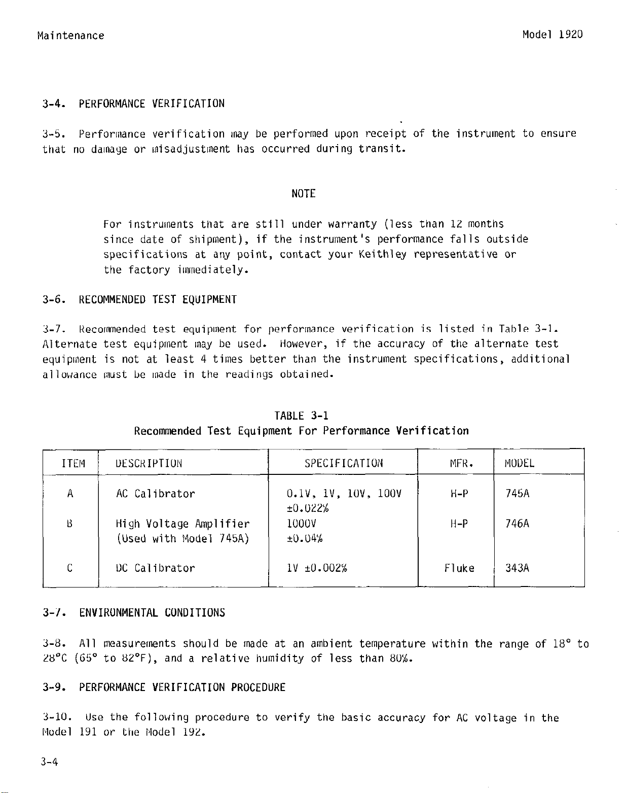
3-4. PERFORMANCE VERIFICATION
Model
1920
3-5.
that no damaye or misadjustment has occurred duriny transit.
Performance verification may be performed upon receipt of the instrument to ensure
NOTE
For instruments that are still under warranty (less than 12 months
since date of shipment), if the instrument's performance falls outside
specifications at any point, contact your Keithley representative or
the factory immediately.
3-6. RECOMMENDED TEST EQUIPMENT
3-7. Kecommended test equipment for performance verification is listed in Table 3-l.
Alternate test equipment may be used.
equipment is not at least 4 times better than the instrument specifications, additional
allowance must be made in the readinys obtained.
Recommended Test Equipment For Performance Verification
However, if the accuracy of the alternate test
TABLE 3-l
ITEM
3-7.
3-8.
28'C (GS" to 82'F), and a relative humidity of less than 8o'k.
3-9. PERFORMANCE VERIFICATION PROCEDURE
ENVIRONMENTAL CONDITIONS
All measurements should be made at an ambient temperature within the range of 18" to
3-10.
Model
191
UESCKIPTIUN
I
AC Calibrator
High Voltage Amplifier
(Used with Model 745A)
UC Calibrator
Use the following procedure to verify the basic accuracy for AC voltage in the
or the Model 192.
I
SPECIFICATION
O.lV, lV,
+O.WzX
1OOOV
+0.04%
1v +0.002x
lOV, 1oov
MFK,
H-P
H-P
Flukl
746A
343A
3-4
Page 15

Model 1920
Performance verification should be performed by qualified personnel
using accurate and reliable test equipment.
3-11. INITIAL CONDITIONS
Maintenance
WARNING
3-12. Before beginning the verification procedure,
the instrument must meet the following
conditions:
A. If the instrument has been subject to extremes of temperature, allow sufficient time
for internal temperatures to reach environmental conditions specified (1X0-28'C).
Typically, it takes one hour to stabilize a unit that is 10°C (1U'F) out of the
specified temperature range.
B. Turn on the instrument and allow it to warm up for two hours before using it with the
Model 192 and one hour before using it with the Model 1Yl.
WARNING
Some procedures require the use of high voltage. Take care to
prevent contact with live circuits which could cause electrical shock
resulting in injury or death.
3-5
Page 16

Maintenance
Model 1920
Performance Verification
2V
2UV
zoov
7oov
2V
ZUV
zoov
2V
NV
2UUV
APPLIED INPUT
AT
1kHz
l.UUUOUV
1o.ouoov
lUO.UUUV
7oo.oov
AT ZUkHz
l.UUUUOV
lU.UUUUV
lUU.UUUV
AT 1UUkHz
l.UUUUUV
lU.UUUUV
lUU.UOUV
For 191
.9965UV to 1.0035UV
9.965OV to 10.035UV
T
99.65UV to 100.35UV
696.55V to 703.45V
.9935UV to l.UU65OV
9.Y35UV to lU.UG5UV
99.35UV to 100.65UV
.985UUV to 1.01500v
9.x5uuv to 10.1500v
Y8.5UOV to 101.5uuv
ALLUWAfJLf
:EAUIIVGS
For
192
.Y9G5UV to 1.0035OV
9.965OV to 10.035UV
99.GWV to lOU.35OV
696.55V to 703.45V
.9935OV to l.UU65UV
9.935011 to lU.UG5OV
99.35UV to lUU.65OV
.985UUV to 1.015uuv
9.85OUV to lU.15OOV
9x.5uuv to lU1.5OOV
7oov
ZUV
zov
ZV
2V
AT 3UkHz
700. oov
AT ZOHz
1o.uuuuv
AT 50Hz
10. ououv
AC + UC Mode
+1.uuouov UC
-1.uuuuuv UC
688.UOV to 712.oov
9.89UUV to 10.1100v
9.89UUV to 10.1100v
L
688.OOV to 712.OOV
Y.89OUV to 10.1100v
9.89UOV to 10.1100v
.995YUV to 1.ou41uv
-.9959uv to -1.uu410
3-6
Page 17

Model 1920
Maintenance
3-13.
3-14.
instrument (191 or lY2). Calibration should be performed when any of the followiny
conditions occur:
3-15. RECOMMENDED TEST EQUIPMENT
3-16. Recommended test equipment for calibration is listed in the following table.
Alternate equipment may be used. However, the accuracy of the alternate equipment must be
at least 4 times better than the Model 1920 specifications,
listed in the Table below.
CALIBRATION
ITEM
This section contains information necessary to calibrate the Model 1920 in your
A. Annually
B. Installation of the 1920
C. Performance Verification indicates 1920 as out of specification
or equal to the specifications
TABLE 3-3
Recommended Test Equipment For Calibration
UESCRIPTION
SPECIFICATION MFK. MOUEL
-
A DC Calibrator
B
C High Voltage Amplifier
II
3-17. ENVIRONMENTAL CONDITIONS
3-18. Calibration should be performed under laboratory conditions having an ambient
temperature of 23
been subjected to temperatures outside of this range, or the higher humidity, allow two
hours minimum for the instrument to stabilize at the specified environmental conditions
before beginning the calibration procedure.
3-19. CALIBRATION PROCEDURE
3-20.
calibration cover.
the instrument to stabilize for two hours before performing the calibration.
AC Calibrator
(Used with Model 74SA)
Calibration Cover
_+l”C,
Remove the top cover of your instrument and replace it with the appropriate
and a relative humidity of less than 70%. If the instrument has
With the calibration cover in place allow the internal temperature of
+1v
r.uw'/
U.lV,
Hl.U22%
IUOUV H-P 746A
+0.04x
lV, lOV, 1uuv
--
Fluke
H-P 745A
Keithley 1913 (191)
343A
3-7
Page 18

Maintenance
Model 1920
WARNING
Some procedures require the use of high voltage. Take care to prevent
contact with live circuits which could cause electrical shock
resulting in injury or death.
R406 C412
R42G
STEP
1
2
*AUJU
3
4
5
6
Model 1920 Calibration Adjustments
TABLE 3-4
Model 1920 Installed in the 192
Calibration Procedure
KANtiE
2
2
KNT: Adjust the UC calibrlator until the display reads 1.00000 +I0 digits.
leads and take note of the reading.
Keadiny is l.U04lJU, adjust K411 to read 1.00200).
?peat Steps and 2 until there is < 10 digits
FWCTIUN
ACV + KY
ACV + UCV
ACV
ACV
INepeat Steps 4 and 5 until they
APPLIEU INPUT
1.lllllloov UC
-1.UOUUUV UC
Adjust K411 to l/Z the difference (Example:
l.UlxlUUV AC
at SUUtir
.llJlJUlJV AC
AUJIJSTMENT
*Calibrator
*K411
I
change in reading from + to -.
K407
K4Z6
are within tolerance.
KEAUINti
I.UOOOO ?lO counts
l.UOOUU QO counts
I
1.00000 ?lO counts
.lOOOlJ i-10 collnts
Keverse th
3-8
Page 19

Wodel
1920
c
I;iP
7
c, mu
Y I 2lJlJu
( 700V AC Max)
10 2UU
20
TABLE 3-4
Model 1920 Installed in the 192
Calibration Procedure (cont.)
FUNCTION APPLIED INPUl AUJUSTMENl
T
ACV
ACV
ACV
ACV
1o.oLwLlv HC
at SUUtir
lUU.UUUV AC
at 5UUtlr
5UU.UUV AC
IUU.UUUV AC
at
1Wktiz
Caution: Use
an insulated
aliynlnent tool
K4U0
K405
K404
C413
Maintenance
KEAUINti
5LlO.UU r10 counts
lOO.llU +25u counts
11
12
13
14
2
20
I
Kepeat Steps lU-12 until no chanye.
Kepeat Steps l-l:! to verify the readings.
tliyh frequency (100kHr) measurements are sensitive to component location.
Uo nut move or bend the components in the input area (C401, iKWJ, etc.)
Kecalibration is necessary if these components are moved.
1UUkHr cannot be brouytit into specification,
section.
Some procedures require the use of high voltage. Use an insulated alignment
tool.
electrical shock resulting in injury or death.
I
Take care to prevent contact with live circuits which could cause
/\cv
ACV
l.UUUUUV AC
at 1UUkHr
lU.UUUUV AC
at 1UUktir
I
NOTE
WARNING
c4u2
C4U7
refer to the troubleshootiny
l.OUOU *50 counts
lU.ULlUU ~100 counts
If the 1uuv
3-9
Page 20

Maintenance
Model 1920
TABLE 3-5
Model 1920 Installed in the 191
Calibration Procedure
STEP
1
2 2 ACV
3 2 ACV
4 2 ACV .lUUUUV AC 11426
:, IRepeat Steps 3 dnd 4 until they are within specification.
ti
7 2uu ACV
8
9,
10
11 20 ACV lU.UUUUV AC c4u7
12 Hepeat Steps 9 thru 11 until no change.
KANtiE
2 ACV
20
zuuu
( 7UOb AC Max)
LOU
ii
FWCTIUI~
ACV
ACV
ACV
ACV
I\PPLIEU INPUT
1UUmV AC
at 50011r
1UmV AC
at SUUHr
l.UUUUUV AC
at SUUHZ
at 5UUHr
11).uouuv AC
at 5UUHz
IUU.UUUV AC
at SUUHZ
suu.ouv AC
lUU.UUUV AC
at 1lJUkHr
l.UUUUUV AC
at 1UUkHz
at 1OUkHr
AUJUSTMENT
K411 Minimum Reading
K411
K4U7 l.UUOUU *lo counts
K4UG
I<405
11404 5u0.00 +10 counts
c413
Caution: Use an
insulated alignment tool.
c4uil 1.0000 +50 counts
KEAUING
Minimum Reading
.lUUUU *lo counts
10.0000 *lo counts
100.000 ?lO counts
100.00 i25ll counts
10.0000 *loo counts
13 Kepeat Steps 1 thru 11 to verify the readings.
NOTE
Hiyh frequency (100kHz) measurements are sensitive to component location.
Do not move or bend the components in the input area (C401, K403, etc.)
Recalibration is necessary if these components are inoved.
1UUkHz cannot be bt-ouyht into specification,
section.
3-22.
3-23. The troubleshootiny instructions contained in this section are intended for
qualified personnel having a basic understanding of analog and digital electronic
principles and components used in precision electronic test equipment. Instructions have
been written to assist in isolating the defective circuit or subcircuit.
specific defective component has been left to the technician.
3-10
Troubleshooting
refer to the troubleshooting
If the 1OUV
Isolation of the
Page 21

Model 1920
NOTE
For 1920's that are still under warranty (less than 12 months
since date of shipment), if the 1920's performance is outside
of specifications at any point,
or the factory before attempting troubleshootiny or repair.
3-24. Troubleshooting Procedure
3-25. Table lists step by step checks of the lnajor circuit blocks of the 1920. Follow
Table 3-G to locate the trouble.
Performance Verification of the Model 1920 is necessary if any of
the following occurs.
contact your Keithley representative
NOTE
Maintenance
1)
Kemoval /rep1 acement of 1920
2) Removal/replacement of shields on the 1920
WARNING
Some procedures require the use of High Voltage. Take care to prevent
contact with live circuits which could cause electrical shock resulting in
injury or death.
TABLE 3-6
Model 1920 Troubleshooting (cont.)
STEP
1
7
8
9
ITEWCOf1PONENT
J1006,
U401, Pin 7
U401, Pin 4
U403, Pin 8
(Brown wire 51008)
U401, Pin G
Q408, Pins 2
Q408, Pin 3
Pin 1
anJ. 5
Turn on Power. Select the
AC function ard 2V range.
t5V <lOOnV AC noise
t15V *lV DC <lOOnV AC noise
-15V +lV DC <lOOnV AC noise
Apply 1 volt at 1ktlZ
1 volt DC
1 Volt AC at IkHZ, no DC Offset
+3V to t8V DC, within
of each other
UV t 25mV
REQUIKEO CONDITIOll KEHAKKS
+5v supply
t15v supply
-15v supply
1920 output
u401 output
1OmV
Differential Output
of Q408
Input summifq junction
Page 22

Maintenance
-
STEP
10
11
12
13
14
Model 1920 Troubleshooting (cont.)
ITEM/COMPONENT
TABLE 3-6
REQUIRED CONDITION
Select 2ov range
a,j apply 1OV AC at 1kHZ
Select 2oov ranye ard
apply 100 V AC at 1kHZ
Select 700V range ard
apply 350V AC at 1kHZ
Select AC + DC function
ard the 2V rarqe. Apply
1v DC
Select AC apply IV DC
Model 1920
KEIlAKKS
(virtual ground)
If display overranges
check (1406 an3 Q407
for gate drive ard
signal
If
display met-ranges
check Q404 ard Q405
for gate drive anl
signal
If display wet-ranges
check Q402 arrl Q403
for gate drive drd
signal
Check display for 1V
if not, check (1401 an3
K401
Oisplay approx. OV
if not, check Q401
K401, c401
NOTE
If the 1OOV 1OUkHz adjustment cannot be brought into specification,
check the spaciny between C4Ul and K403. If these components have
been bent toward or away from each other, C413 may not have adequate
calibration ranye.
1OOkHz response on all ranges.
Moviny C401 and K403 closer toyether increases the
Check and adjust, if necessary.
3-12
Page 23

Model 1920
SECTION 4. MODEL 1920 THEORY OF OPERATION
4-l. The Model 1920 is a plug in AC(+UC) to RMS converter with variable yain. The gain
factor conditions the AC input voltaye for application to the A/U converter.
4-2. The input siynal is applied through GIN (0.05uF) and KIN (2Mrl) to 4408. For
AC+UC operation GIN is shorted by Relay K4Ul.
variable yain inverting type with gain from-U.001 to-l (see table below). The gain is
selected accordingly by the double FET switches Q402-Q407. Two FETs are used for each
range.
K41G to effectively attenuate high frequency (1UUkHz) signals.
They are configured in a T-type attenuator with the 1Uk resistors K413, K414 and
The two stage amplifier (op amp) is a
Theory of Operation
4-3.
Q408. 4408 allows the reduction of input bias current.
because an auto zero cycle is not possible on the AC or AC+UC functions. Any input bias
current will show up as an input offset voltage.
u401. The output of U4Ul is applied to the KMS converter U403. C409, C41U and K42U make
up the two pole filter that is located at the output of U403. The output of U403 is a UC
signal which is applied to the A/U converter.
auto zero A/D input by adjusting R426.
output offset.
The op amp is a two stage amplifier. The first stage is confiyured around dual FET
This reduction is necessary
The second stage is configured around
A small UC offset may be applied to the
This allows compensation for the KMS converter's
TABLE 4-l
Ranging Information
Ranye tiain
2v 1
2ov
2ouv
7UOV
l/10 (217k f"K4U6) 11 2M
l/100 (19.6k + K405)1) 2M
l/lOUU
UP Amp Feedback Resistance Engergized FETs
None
Q406, q4u7
Q404, Q405
(2.12k + K404)I)
(19.GK + R405)1/ 2M
Q402, Q403,
Q404, Q4U5
.I
4-1
Page 24

-
Model 1920 Biock Diagram
FET
Orive
Range
-
Select
Page 25

Model 1920
Repldieabl
e Parts
SECTION 5.
5-l.
5-2. This section contains information for ordering replacement parts. The replaceable
5-3.
5-4.
General
parts list is arranged in alphabetical order of the circuit designations of the
components.
given in Table 5-1.
Ordering Information
To place an order or to obtain information concerning replacement parts contact your
Keithley representative or the factory.
When ordering,
a. Instrument Model Number
Instrument Serial Number
b.
c. Part Uescription
Circuit Designation (if applicable)
d.
e. Keithley Part Number
A crass reference list of manufacturers containing their addresses is
include the following information:
REPLACEABLE PARTS
See the inside front cover for addresses.
5-5. Factory Service
5-6. If the instrument is to be returned to the factory for service, please complete the
Service Form which follows this section and return it with the instrument.
5-7. Schematic and Component Layout
5-B. The Schematic and Component Layout follow this section.
TABLE 5-l
Cross Reference of Manufacturers
MFti Code
A-U
BKN
NAME AND AUURESS
Analog Uevices, Inc.
Norwood, MA 02026
Bourns, Inc.
Kiverside, CA 92507
FEUEKAL SUPPLY COUE
01121
80294
5-l
Page 26

Replaceable Parts
Model 1920
TABLE 5-l
Cross Reference of Manufacturers (cont.)
MFti Code
c-u
CLU
CLK
ULE
EC1
EFJ
INAME ANU AUUKESS
Cornell-Uubilier
Newark, NJ 07101
Centralab Uivision
Milwaukee, WI 532021
Clarostat Manufacturing Co.
Uover, NH 03820
Uale Electronics
Columbus, NE 68601
Electra-Cube, Inc.
San Gabriel, CA
E. F. Johnson Co.
Waseca, MN 56093
91776
FEUERAL SUPPLY CODE
1
14655
71590
12697
91637
14752
74979
EKI
INT
K-I
NAT
N I c
NYT
MEP
Erie Technological Products
Erie, PA
Intersil,
Cupertino, CA
Keithley Instruments, Inc.
Cleveland, Ohio 44139
National Semi Corp.
Santa Clara, CA 95051
Nichicon Corp.
Chicago, IL 60645
Nytronics Components Group
Darlington, SC 29532
Mepco, Inc.
Morristown,
16512
Inc.
95014
NJ 07960
72982
32294
80164
27014
83125
80031
-
5-2
Page 27

Model 1920 Replaceable Parts
TABLE 5-1
Cross Reference of Manufacturers (cont.)
MFG Code
PKP
SIL
STD
T-I
NAME ANU AUUKESS
Precision Kesistive Products
Mediapolis, IA 53237
Siliconix, Inc.
Santa Clara, CA 95054
Standard Condenser
Chicago, IL
Texas Instruments,
Uallas, TX 75231
Inc.
FEUERAL SUPPLY COUE
17856
97419
01295
5-3
Page 28

Replaceable Parts
Model 1920
TABLE 5-2
Replaceable Parts List (cont.)
Circuit Schematic PC-Board Mfr. Mfr.
Lksig. Description
c401 .05,#, lUUUV, Metal Poly A4 5/EZ STU CAPACPLYEEOX
c402 .25pF to 1.5pF, ZOOUV Trimmer 23 6/E2
c403
c404 luF, 16V, Alum Elect 04 8/E2
c4u5 33OpF, 5OUV, Poly
C406 3llpF. 5OUV, Mica
c407 .25pF to 1.5pF, 2UUUV,
c4w luF, 5UV, Metal Poly F4 12/c3
C4OY
c41u
c411 33pF, 5UlJV, Mica 04
c412 G.BpF, SOV, Tube Cer
c413 .25pF tu l.SpF, XJOOV, u4
IpF, XV, Alum Elect tI3 7/u
Trimmer
l,,F, SUV, Metal Poly FS 13/c3
l"F, 5UV, Metal Poly F5
Trimmer
Location Item No./Location Code Lksig.
EFJ 273-0001-002 31863A
NIC SOVKBID c-325-1.0
NIC SIJVKBIU c-325-1.0
Cl Y/D2 CLtJ CPK330J C-138-33UpF
c2 IO/D2 C-O
c3
11/w
14/C3 EC1 62513
15/w C-D
lUU/W ERI
101/u K-I 273.OOUl-002
K-l 273-0001-002 3186311
EC1 625U
EC1 6258 c-335-1.0
UClOEUUOJ3 C-236-30pF
UClUEU3OUJ3 C236-33pF
301.oooco c-282-6.8pF
HO15
Keithley
Part No.
C-285-.05
c-335-1.0
c-335-1.0
3186311
102/E2
CKL KlCC2U
IN914
IN914
IN914
C-77-0.75pF
RF-28
RF-28
RF-28
KL-69
5-4
Page 29

Model 1920
Circuit
lksig.
Description
TABLE 5-2
laceable Parts List (cont.)
thematic
ocati on
PC-Board
I
,tem No./Location
Mfr.
Code
Mfr.
Desig.
Replaceable Parts
T
Keithley
Part No.
L401
L4U2
q401
q402
q403
4404
q405
4406
4407
441)s
R401
R4O2
R403
R404
lUU,,H Choke
lOU$l Choke
Transistor, PNP
N-Channel JFET (selected)
N-Channel JFET
N-Channel JFET (selected)
N-Channel JFET
N-Channel JFET (selected)
N-Channel JFET
Uual N-Channel JFET
lk, 1%. 1/2W, rntf
lk, I%, i/ZW, lntf
2M,
.5x,
lW, mtf
Pot, lUUl1, lor, 3/4w
A3
A3
nz
lx
E2
u2
E2
II3
E3
c4
84
04
B4
CZ
17/w
l&l/U3
34lE3
35/U2
36102
37/w
38/U2
39/w
4U/U2
41/E2
57/F2
58!FZ
5Y/E2
(IU/UZ
NYT
NYT
A-U
K-I
INT
K-l
INT
K-l
INT
SIL
ULE
ULE
ULE
BRN
swu-100
swu-1uu
AU-820
lTE43Y2
lTE4392
ITE4392
E411
MFF-l/2
MFF-l/2
MFF-l/2-31
36UU, IiPlUU
CH-14
CM-14
Tti-84
TG-128
Tti-77
Tti-128
Tti-77
FIG-12X
TG-77
Tti-118
K-94-lk
K-Y4-lk
K-303-21.1
IRP-XY-100
R405
R406
R407
R408
R409
K410
R411
Pot, lk,
Pot, 1Uk. lOY, 3/4W
Pot, lk, lo%, 3/4W
2.12k,
19.6k, .a, l/IIW, mtf
217k,
Pot, lOk, lo'b, 3/4W
.Yb,
.5x,
lo’b,
1/8W, intf
1/8W,
J/4W
mtf
C2
C3
F5
c2
CZ
C3
05
61/02
62/W
63/1)2
64102
65lU2
a/u2
67lE2
BRN
BRN
BHN
ULE
ULE
OLE
URN
3600, GPlOUU
36OO, GPlOUUU
3600,
tiPlOO
MFF
l/U
MFF-l/8
MFF-l/8
3600, GPlOUOO
KP-XY-lk
RP-&l9-1Ok
KP-89-lk
R-246-2.12k
R-246-19.6k
K-246-217k
RP-89-1Ok
5-5
Page 30

Reolaceable Parts
Circuit
Desig.
R412
Iescription
LM, 5X, 1/4W, Carb
TABLE 5-2
Replaceable Parts List (cant
ichematic
.ocation
PC-Board
tern No./Location
t-
U2
68/C2
Mfr.
Code
MEP
Yfr.
Jesig.
X25*
Model 19'20
Keithley
Part No.
R-76.1M
R413
R414
11415
K416
K417
K418
11419
R420
K421
R422
11423
K424
R425
K426
K427
K428
LUk, 5'h, 1/4W, Carb
IOk, 5%, 1/4W, Carb
LM, 5%. 1/4W, Carb
lOk, Y/S, 1/4W, Garb
lM, 5X, 1/4W Carb
ZM, .b%, 1/8W, i&f
j.65k, lY, l/ilW, mtf
24k, 5X, 1/4W, Carb
IOk, I%, 1/8W, mtf
2.20, 5X, 1/4W, Carb
Z.Zk, 5%. 1/4W, Carb
J.3k, 5X, 1/4W, Carb
2.2k,
5y,
1/4W, Cat-b
Pot, lOk, lo%, 1/2W.
2.2k, 5$, 1/4W. Garb
49912, la, l/&l, mtf
UZ
II3
U3
u3
U3
c4
04
F5
F2
GZ
F4
G4
A2
F2
F5
E5
69/U
7o/c3
7l/C3
72ic3
73/a
74/E2
75/U2
76JC3
77/u
78/C?!
7Y/CZ
UUICZ
Xl/E2
82/C2
83/U3
84/w
MEP
MEP
MEP
MEP
MEP
ULE
PRP
MEP
PRP
MEP
MEP
MCP
MEP
URN
MEP
PRP
CK25*
CK25*
CK25*
CK25*
CR25*
YFF-l/II
**
CR25*
**
CK25*
CR25*
CR25*
CRZS*
3386H-1-103
UK25*
**
IK-76-1Ok
IK-76-10k
K-76.1M
H-76-1UK
K-76-1M
IR-246-2M
K-88-3.65k
IR-76.24k
IK-88.1Ok
R-76-2.2
R-76.2.2k
IK-76-3.3k
R-76-2.2k
KP-111.1Ok
K-76-2.2k
R-88-499
R42Y
lK430
K431
H432
K433
K434
CK25* Manufacturers Uesignation includes parts description e.g. CK25 33k, 5'6, 1/4W, Carb for 11434
**
SG.Zk, .5x,
56.2k, .5%, l/SW, mtf
44.2k, I%, 1/8W, mtf
lOk, 5X, 1/4W, Carb
16.9n, 1X, l/&J, mtf
33k, 5X, 1/4W, Carb
Manufacturers &sign&ion is GP1/4, 1X, 7100, Kesistance value
1/8W,
mtf
c4
C4
c5
c5
c5
u4
85/E2
86/U2
87/E2
@S/E2
89/U
YO/OZ
ULE
ULE
PKP
MEP
PKP
MEP
MFF-l/8
MFF-l/8
**
cn25*
**
CR25*
5-6
K-246-56.2k
K-246-56.2k
R-88-44.2k
R-76-10k
K-88-16.9
R-76-33k
Page 31

Model 1920
Circuit
Uesiq.
TABLE 5-2
RI
laceable Parts List (cont.)
2P
khematic
1
aation
Mfr.
Code
Replaceable Parts
Mfr.
Desig.
u401
u4w
u4u3
I
VOI tage Quad comparator
t
u4
I73,4
E5
41/u
4Y/U3
1:
49/u3
NAT
LF356H
LM339
AUS36AK
5-7
Page 32

Page 33

Page 34

KEITHLEY INSTRUMENTS, INC.
28775 AURORA ROAD
CLE'.'ELAND, OHIO 44139
SERViCE FORWl
MODEL NO. SERIAL ?lO,~
NAME
COMPANY
ADDRESS
I3 :
El
_. ,--- _..~___
Describe problem and symptoms using quantitative data whenever possible (enclose
readings, chart recordings, etc.)
Show a block diagram of your measurement system including all instruments connected
(whether power is turned on or not). Also describe signal source.
P.O. NO. DATE R-
PHONE
CITY
(Attach additional sheets as necessary).
STATE
1
ZIP
List the positions of alJ controls and switches on both front and rear panels of
q
El
the instrument.
Describe input signal source levels, frequencies, etc.
List and describe all cables used in the experiment (length, shielding, etc.).
q .
List and describe all other equipment used in the experiment. Give control settings
q
for each.
Environment:
El
Where is the measurement being performed?
out-of-doors, etc.)
What power line volt=is used?
Ambient temperature?
Other
"F. Variation?
(Factory, controlled laboratory,
Variation? Frequency?
"F. Rel. Humidity?
Additional Information. (If special modifications have been made by the user,
lxl
please describe below.)
REV 0774
Page 35

 Loading...