

Page 1

Operator’s Manual
1780R-Series Video Measurement Set
070-6890-08
This document supports firmware version 1.10 to
1.16.
Page 2

Copyright © Tektronix, Inc. All rights reserved. T ektronix products are covered by U.S. and foreign patents, issued and
pending. Information in this publication supercedes that in all previously
published material. Specifications and price change privileges reserved.
T ektronix, Inc., P.O. Box 1000, Wilsonville, OR 97070–1000
TEKTRONIX and TEK are registered trademarks of T ektronix, Inc.
Page 3

Page 4

WARRANTY
Tektronix warrants that the products that it manufactures and sells will be free from defects
in materials and workmanship for a period of three (3) years from the date of shipment. If a
product proves defective during this warranty period, Tektronix, at its option, either will
repair the defective product without charge for parts and labor, or will provide a
replacement in exchange for the defective product.
In order to obtain service under this warranty, Customer must notify Tektronix of the
defect before the expiration of the warranty period and make suitable arrangements for the
performance of service. Customer shall be responsible for packaging and shipping the
defective product to the service center designated by Tektronix, with shipping charges
prepaid. Tektronix shall pay for the return of the product to Customer if the shipment is to
a location within the country in which the Tektronix service center is located. Customer
shall be responsible for paying all shipping charges, duties, taxes, and any other charges for
products returned to any other locations.
This warranty shall not apply to any defect, failure or damage caused by improper use or
improper or inadequate maintenance and care. Tektronix shall not be obligated to furnish
service under this warranty a) to repair damage resulting from attempts by personnel other
than Tektronix representatives to install, repair or service the product; b) to repair damage
resulting from improper use or connection to incompatible equipment; c) to repair any
damage or malfunction caused by the use of non-Tektronix supplies; or d) to service a
product that has been modified or integrated with other products when the effect of such
modification or integration increases the time or difficulty of servicing the product.
THIS WARRANTY IS GIVEN BY TEKTRONIX IN LIEU OF ANY OTHER
WARRANTIES, EXPRESS OR IMPLIED. TEKTRONIX AND ITS VENDORS
DISCLAIM ANY IMPLIED WARRANTIES OF MERCHANTABILITY OR
FITNESS FOR A PARTICULAR PURPOSE. TEKTRONIX’ RESPONSIBILITY
TO REPAIR OR REPLACE DEFECTIVE PRODUCTS IS THE SOLE AND
EXCLUSIVE REMEDY PROVIDED TO THE CUSTOMER FOR BREACH OF
THIS WARRANTY. TEKTRONIX AND ITS VENDORS WILL NOT BE LIABLE
FOR ANY INDIRECT, SPECIAL, INCIDENTAL, OR CONSEQUENTIAL
DAMAGES IRRESPECTIVE OF WHETHER TEKTRONIX OR THE VENDOR
HAS ADVANCE NOTICE OF THE POSSIBILITY OF SUCH DAMAGES.
Page 5

Contacting Tektronix
Product
Support
Service
Support
For other
information
To write us Tektronix, Inc.
Website T ektronix.com
For questions about using T ektronix measurement
products, call toll free in North America:
1-800-TEK-WIDE (1-800-835-9433 ext. 2400)
6:00 a.m. – 5:00 p.m. Pacific time
Or contact us by e-mail:
tm_app_supp@tek.com
For product support outside of North America,
contact your local T ektronix distributor or sales
office.
T ektronix offers extended warranty and calibration
programs as options on many products. Contact
your local T ektronix distributor or sales office.
For a listing of worldwide service centers, visit our
web site.
In North America:
1-800-TEK-WIDE (1-800-835-9433)
An operator will direct your call.
P.O. Box 1000
Wilsonville, OR 97070-1000
USA
Page 6

Page 7

Table of Contents
General Safety Summary xi. . . . . . . . . . . . . . . . . . . . . . . . . . . .
Getting Started
Documentation Overview 1–1. . . . . . . . . . . . . . . . . . . . . . . . . . . . .
Operator’s Manual 1–1. . . . . . . . . . . . . . . . . . . . . . . . . . . . . . . .
Service Manual 1–1. . . . . . . . . . . . . . . . . . . . . . . . . . . . . . . . . .
Documentation Conventions 1–2. . . . . . . . . . . . . . . . . . . . . . . . . . .
Who Should Use This Operator’s Manual 1–2. . . . . . . . . . . . . . . . .
1780R-Series Product Overview 1–2. . . . . . . . . . . . . . . . . . . . . . . .
New Capabilities 1–3. . . . . . . . . . . . . . . . . . . . . . . . . . . . . . . . .
T ouch Screen 1–3. . . . . . . . . . . . . . . . . . . . . . . . . . . . . . . . . . . .
1780R-Series Package 1–4. . . . . . . . . . . . . . . . . . . . . . . . . . . . . . . .
Mechanical Installation 1–4. . . . . . . . . . . . . . . . . . . . . . . . . . . . . . .
Rack-Mounting 1–4. . . . . . . . . . . . . . . . . . . . . . . . . . . . . . . . . . . . .
Options 1–9. . . . . . . . . . . . . . . . . . . . . . . . . . . . . . . . . . . . . . . . . . . .
Standard Accessories 1–9. . . . . . . . . . . . . . . . . . . . . . . . . . . . . . . . .
Optional Accessories 1–10. . . . . . . . . . . . . . . . . . . . . . . . . . . . . . . . .
Connectors, Controls, Indicators
Switches 2–1. . . . . . . . . . . . . . . . . . . . . . . . . . . . . . . . . . . . . . . .
Companion Switches 2–1. . . . . . . . . . . . . . . . . . . . . . . . . . . . . .
Controls 2–1. . . . . . . . . . . . . . . . . . . . . . . . . . . . . . . . . . . . . . . .
LEDs 2–1. . . . . . . . . . . . . . . . . . . . . . . . . . . . . . . . . . . . . . . . . .
Audio Feedback (Beep) 2–2. . . . . . . . . . . . . . . . . . . . . . . . . . . . . . .
A Beep Sounds When: 2–2. . . . . . . . . . . . . . . . . . . . . . . . . . . . .
Disable the Beep 2–2. . . . . . . . . . . . . . . . . . . . . . . . . . . . . . . . .
A “Click” Occurs When: 2–2. . . . . . . . . . . . . . . . . . . . . . . . . . .
T ouch Screen 2–2. . . . . . . . . . . . . . . . . . . . . . . . . . . . . . . . . . . . . . .
Front-Panel Controls 2–3. . . . . . . . . . . . . . . . . . . . . . . . . . . . . . . . .
1780R-Series Operator’s Manual
i
Page 8

T able of Contents
Power 2–3. . . . . . . . . . . . . . . . . . . . . . . . . . . . . . . . . . . . . . . . . .
CR T Controls 2–3. . . . . . . . . . . . . . . . . . . . . . . . . . . . . . . . . . . .
Precision Measurement (Large Knob) 2–5. . . . . . . . . . . . . . . . .
Menu Access Switches 2–7. . . . . . . . . . . . . . . . . . . . . . . . . . . .
Probe 2–8. . . . . . . . . . . . . . . . . . . . . . . . . . . . . . . . . . . . . . . . . .
Display Mode 2–9. . . . . . . . . . . . . . . . . . . . . . . . . . . . . . . . . . . .
Ref 2–12. . . . . . . . . . . . . . . . . . . . . . . . . . . . . . . . . . . . . . . . . . . .
Wfm Horizontal 2–12. . . . . . . . . . . . . . . . . . . . . . . . . . . . . . . . . .
Magnifier 2–12. . . . . . . . . . . . . . . . . . . . . . . . . . . . . . . . . . . . . . .
Gain 2–13. . . . . . . . . . . . . . . . . . . . . . . . . . . . . . . . . . . . . . . . . . .
Filter 2–14. . . . . . . . . . . . . . . . . . . . . . . . . . . . . . . . . . . . . . . . . . .
Input 2–15. . . . . . . . . . . . . . . . . . . . . . . . . . . . . . . . . . . . . . . . . . .
Rear Panel Connectors 2–16. . . . . . . . . . . . . . . . . . . . . . . . . . . . . . . .
Operating Instructions
Large Knob And Associated Switches 3–1. . . . . . . . . . . . . . . . . . .
Timing Cursors 3–1. . . . . . . . . . . . . . . . . . . . . . . . . . . . . . . . . .
Voltage Cursors 3–2. . . . . . . . . . . . . . . . . . . . . . . . . . . . . . . . . .
Line Select 3–3. . . . . . . . . . . . . . . . . . . . . . . . . . . . . . . . . . . . . .
Phase Shift 3–5. . . . . . . . . . . . . . . . . . . . . . . . . . . . . . . . . . . . . .
Reference Set 3–5. . . . . . . . . . . . . . . . . . . . . . . . . . . . . . . . . . . .
Knob 3–6. . . . . . . . . . . . . . . . . . . . . . . . . . . . . . . . . . . . . . . . . . .
< > Switches 3–6. . . . . . . . . . . . . . . . . . . . . . . . . . . . . . . . . . . . .
Graticules 3–6. . . . . . . . . . . . . . . . . . . . . . . . . . . . . . . . . . . . . . . . . .
Scale Illumination for Vector and Waveform Graticules 3–6. . .
Using The Vector Graticule 3–6. . . . . . . . . . . . . . . . . . . . . . . . .
Using The Waveform Graticule 3–12. . . . . . . . . . . . . . . . . . . . . .
Remote Operation 3–15. . . . . . . . . . . . . . . . . . . . . . . . . . . . . . . . . . .
REMOTE Connector 3–15. . . . . . . . . . . . . . . . . . . . . . . . . . . . . .
Remote Operation 3–15. . . . . . . . . . . . . . . . . . . . . . . . . . . . . . . .
Serial Communications Interface 3–18. . . . . . . . . . . . . . . . . . . . . . .
Serial Interface Connector 3–18. . . . . . . . . . . . . . . . . . . . . . . . . .
Building a Wiring Converter 3–18. . . . . . . . . . . . . . . . . . . . . . . .
Serial Remote Information 3–19. . . . . . . . . . . . . . . . . . . . . . . . . .
SCH Display 3–21. . . . . . . . . . . . . . . . . . . . . . . . . . . . . . . . . . . . . . .
SCH Phase Measurement Procedure 3–22. . . . . . . . . . . . . . . . . .
ii
1780R-Series Operator’s Manual
Page 9

T able of Contents
Parade Operation 3–23. . . . . . . . . . . . . . . . . . . . . . . . . . . . . . . . . . . .
T wo Line or Field Parade 3–23. . . . . . . . . . . . . . . . . . . . . . . . . . .
Three Line Display 3–23. . . . . . . . . . . . . . . . . . . . . . . . . . . . . . .
Offset Menu 3–23. . . . . . . . . . . . . . . . . . . . . . . . . . . . . . . . . . . . .
DC Level Measurements 3–24. . . . . . . . . . . . . . . . . . . . . . . . . . .
DC Level Measurement Procedure 3–25. . . . . . . . . . . . . . . . . . .
Overlay Operation 3–26. . . . . . . . . . . . . . . . . . . . . . . . . . . . . . . . . . .
Overlaid Displays 3–26. . . . . . . . . . . . . . . . . . . . . . . . . . . . . . . . .
Offset Menu 3–26. . . . . . . . . . . . . . . . . . . . . . . . . . . . . . . . . . . . .
WFM + CAL 3–27. . . . . . . . . . . . . . . . . . . . . . . . . . . . . . . . . . . . . . .
Enter WFM+CAL Mode 3–27. . . . . . . . . . . . . . . . . . . . . . . . . . .
General WFM+CAL Information 3–27. . . . . . . . . . . . . . . . . . . .
Menu Information 3–31. . . . . . . . . . . . . . . . . . . . . . . . . . . . . . . . . . .
Menu Documentation Overview 3–31. . . . . . . . . . . . . . . . . . . . .
Menu Access 3–32. . . . . . . . . . . . . . . . . . . . . . . . . . . . . . . . . . . .
T ouch Screen 3–32. . . . . . . . . . . . . . . . . . . . . . . . . . . . . . . . . . . .
Password Menu 3–34. . . . . . . . . . . . . . . . . . . . . . . . . . . . . . . . . . . . .
Enable / Disable the Password 3–34. . . . . . . . . . . . . . . . . . . . . . .
Define the Password 3–34. . . . . . . . . . . . . . . . . . . . . . . . . . . . . .
Change the Password 3–35. . . . . . . . . . . . . . . . . . . . . . . . . . . . . .
Use the Password 3–35. . . . . . . . . . . . . . . . . . . . . . . . . . . . . . . . .
Incorrect Password 3–35. . . . . . . . . . . . . . . . . . . . . . . . . . . . . . . .
Preset Menu 3–36. . . . . . . . . . . . . . . . . . . . . . . . . . . . . . . . . . . . . . . .
Recall 3–36. . . . . . . . . . . . . . . . . . . . . . . . . . . . . . . . . . . . . . . . . .
Recover 3–38. . . . . . . . . . . . . . . . . . . . . . . . . . . . . . . . . . . . . . . .
Store 3–39. . . . . . . . . . . . . . . . . . . . . . . . . . . . . . . . . . . . . . . . . . .
Name 3–40. . . . . . . . . . . . . . . . . . . . . . . . . . . . . . . . . . . . . . . . . .
Calibrate Menu 3–42. . . . . . . . . . . . . . . . . . . . . . . . . . . . . . . . . . . . .
General Calibration Menu Information 3–42. . . . . . . . . . . . . . . .
Waveform Calibration Information 3–42. . . . . . . . . . . . . . . . . . .
Waveform Calibration Procedure 3–43. . . . . . . . . . . . . . . . . . . . .
Vectorscope Calibration Information 3–46. . . . . . . . . . . . . . . . . .
Vectorscope Calibration Procedure 3–46. . . . . . . . . . . . . . . . . . .
Vectorscope Calibration Procedure 3–49. . . . . . . . . . . . . . . . . . .
Configure Menu 3–52. . . . . . . . . . . . . . . . . . . . . . . . . . . . . . . . . . . . .
Changing Configurations 3–52. . . . . . . . . . . . . . . . . . . . . . . . . . .
1780R-Series Operator’s Manual
iii
Page 10

T able of Contents
Measure Menu 3–56. . . . . . . . . . . . . . . . . . . . . . . . . . . . . . . . . . . . . .
Using the Measure Menu 3–56. . . . . . . . . . . . . . . . . . . . . . . . . . .
Beep 3–57. . . . . . . . . . . . . . . . . . . . . . . . . . . . . . . . . . . . . . . . . . .
Store and Recall Modified Setups 3–57. . . . . . . . . . . . . . . . . . . .
Making Measurements 3–58. . . . . . . . . . . . . . . . . . . . . . . . . . . . .
Measurements
Measurement Information 4–1. . . . . . . . . . . . . . . . . . . . . . . . . . . . .
Differential Phase Measurement 4–2. . . . . . . . . . . . . . . . . . . . . . . .
Enter DIFF PHASE Mode 4–2. . . . . . . . . . . . . . . . . . . . . . . . . .
Exit DIFF PHASE Mode 4–2. . . . . . . . . . . . . . . . . . . . . . . . . . .
DIFF PHASE Menu Selections 4–2. . . . . . . . . . . . . . . . . . . . . .
DIFF PHASE Measurement Information 4–5. . . . . . . . . . . . . .
Single-Trace DIFF PHASE Measurement Procedure 4–5. . . . .
Double-Trace DIFF PHASE Measurement Procedure 4–6. . . .
Using Line Select in DIFF PHASE 4–6. . . . . . . . . . . . . . . . . . .
Differential Gain Measurement 4–7. . . . . . . . . . . . . . . . . . . . . . . . .
Enter DIFF GAIN Mode 4–7. . . . . . . . . . . . . . . . . . . . . . . . . . .
Exit DIFF GAIN Mode 4–7. . . . . . . . . . . . . . . . . . . . . . . . . . . .
DIFF GAIN Menu Selections 4–7. . . . . . . . . . . . . . . . . . . . . . .
DIFF GAIN Measurement Information 4–10. . . . . . . . . . . . . . . .
Single-Trace DIFF GAIN Measurement Procedure 4–10. . . . . .
Double-Trace DIFF GAIN Measurement Procedure 4–11. . . . . .
Using Line Select in DIFF GAIN 4–11. . . . . . . . . . . . . . . . . . . .
Simultaneous Diff Phase & Diff Gain Measurements 4–12. . . . . . . .
Enter DP & DG Mode 4–12. . . . . . . . . . . . . . . . . . . . . . . . . . . . .
Exit DP & DG Mode 4–12. . . . . . . . . . . . . . . . . . . . . . . . . . . . . .
DP & DG Menu Selections 4–12. . . . . . . . . . . . . . . . . . . . . . . . .
DP & DG Measurement Information 4–14. . . . . . . . . . . . . . . . . .
DIFF PHASE & DIFF GAIN Measurement Procedure 4–15. . .
Noise Measurement 4–16. . . . . . . . . . . . . . . . . . . . . . . . . . . . . . . . . .
Enter Noise Measurement Mode 4–16. . . . . . . . . . . . . . . . . . . . .
Exit Noise Measurement Mode 4–16. . . . . . . . . . . . . . . . . . . . . .
Noise Measurement Procedure 4–16. . . . . . . . . . . . . . . . . . . . . .
ICPM Measurement 4–17. . . . . . . . . . . . . . . . . . . . . . . . . . . . . . . . . .
Enter ICPM Measurement Mode 4–17. . . . . . . . . . . . . . . . . . . . .
Exit ICPM Measurement Mode 4–17. . . . . . . . . . . . . . . . . . . . . .
ICPM Measurement Information 4–17. . . . . . . . . . . . . . . . . . . . .
ICPM Measurement Procedure 4–18. . . . . . . . . . . . . . . . . . . . . .
iv
1780R-Series Operator’s Manual
Page 11

T able of Contents
K Factor Measurement 4–20. . . . . . . . . . . . . . . . . . . . . . . . . . . . . . .
Enter K Factor Mode 4–20. . . . . . . . . . . . . . . . . . . . . . . . . . . . . .
Making K Factor Measurements 4–20. . . . . . . . . . . . . . . . . . . . .
Chroma / Luma Inequalities Measurement 4–23. . . . . . . . . . . . . . . .
Enter Chroma / Luma Mode 4–23. . . . . . . . . . . . . . . . . . . . . . . .
Exit Chroma / Luma Mode 4–23. . . . . . . . . . . . . . . . . . . . . . . . .
Cursors in Chroma / Luma 4–23. . . . . . . . . . . . . . . . . . . . . . . . . .
Making Chroma / Luma Measurements (Using Cursors) 4–23. .
Chroma / Luma Measurements with Lissajous Display 4–27. . .
Short-Time Distortion Measurement 4–28. . . . . . . . . . . . . . . . . . . . .
Enter Short-Time Distortion Mode 4–28. . . . . . . . . . . . . . . . . . .
Exit Short-Time Distortion Measurement Mode 4–28. . . . . . . . .
Short-Time Distortion Measurement Procedure 4–28. . . . . . . . .
R–Y Sweep Measurement 4–31. . . . . . . . . . . . . . . . . . . . . . . . . . . . .
Enter R–Y Sweep Mode 4–31. . . . . . . . . . . . . . . . . . . . . . . . . . .
Exit R–Y Sweep Measurement Mode 4–31. . . . . . . . . . . . . . . . .
R–Y Sweep Mode Information 4–32. . . . . . . . . . . . . . . . . . . . . .
Using R–Y Sweep Mode 4–32. . . . . . . . . . . . . . . . . . . . . . . . . . .
Bowtie Measurement 4–33. . . . . . . . . . . . . . . . . . . . . . . . . . . . . . . . .
Enter Bowtie Measurement Mode 4–33. . . . . . . . . . . . . . . . . . . .
Bowtie Measurement Procedure 4–33. . . . . . . . . . . . . . . . . . . . .
Time Marks Measurement 4–36. . . . . . . . . . . . . . . . . . . . . . . . .
F
SC
Enter F
Exit FSC Time Marks Measurement Mode 4–36. . . . . . . . . . . . .
Making SCH Phase Measurements 4–37. . . . . . . . . . . . . . . . . . .
Voltage Cursors in FSC Time Marks Mode 4–37. . . . . . . . . . . . .
Verifying Burst Position 4–37. . . . . . . . . . . . . . . . . . . . . . . . . . . .
Other Measurements 4–38. . . . . . . . . . . . . . . . . . . . . . . . . . . . . . . . .
Time Marks Measurement Mode 4–36. . . . . . . . . . . .
SC
Specifications
Options and Accessories
Options 6–1. . . . . . . . . . . . . . . . . . . . . . . . . . . . . . . . . . . . . . . . . . . .
Accessories 6–1. . . . . . . . . . . . . . . . . . . . . . . . . . . . . . . . . . . . . . . .
Standard Accessories 6–1. . . . . . . . . . . . . . . . . . . . . . . . . . . . . .
Optional Accessories 6–2. . . . . . . . . . . . . . . . . . . . . . . . . . . . . .
Index
1780R-Series Operator’s Manual
v
Page 12

T able of Contents
List of Figures
Figure 1–1: Location of the four screws that secure the
instrument to rack-mounting cabinet or portable case 1–5.
Figure 1–2: Dimensions used for rack-mounting the
1780R-Series Video Measurement Set 1–6. . . . . . . . . . . . . . .
Figure 1–3: Dimensions of the adjustable rear
rack-mounting bracket 1–7. . . . . . . . . . . . . . . . . . . . . . . . . . .
Figure 1–4: Installing rear rack-mounting brackets for rack
applications of depths from 18 to 24 inches 1–8. . . . . . . . . . .
Figure 2–1: Left side of front panel 2–4. . . . . . . . . . . . . . . . . . . .
Figure 2–2: Right side of front panel 2–10. . . . . . . . . . . . . . . . . . .
Figure 2–3: Rear-Panel Connectors 2–17. . . . . . . . . . . . . . . . . . . .
Figure 3–1: Line Select Menu Screen with <2 OF 4> Fields
selected 3–4. . . . . . . . . . . . . . . . . . . . . . . . . . . . . . . . . . . . . . . .
Figure 3–2: Line Select Menu Screen with <1 OF 8> Fields
selected 3–5. . . . . . . . . . . . . . . . . . . . . . . . . . . . . . . . . . . . . . . .
Figure 3–3: 1780R Vector Graticule 3–7. . . . . . . . . . . . . . . . . . .
Figure 3–4: 1781R Vector Graticule 3–8. . . . . . . . . . . . . . . . . . .
Figure 3–5: Rear-panel X–Y Connector Pin Assignments 3–11. .
Figure 3–6: 1780R Waveform Graticule 3–12. . . . . . . . . . . . . . . .
Figure 3–7: 1781R Waveform Graticule 3–13. . . . . . . . . . . . . . . .
Figure 3–8: REMOTE Connector Pin Assignments 3–15. . . . . . .
Figure 3–9: Serial Interface Connector Pin Assignments 3–18. .
Figure 3–10: Serial Interface Connector Wiring Converter 3–19
Figure 3–11: Portion of the 1780R-Series Front Panel 3–21. . . . .
Figure 3–12: Offsets Menu Screen 3–24. . . . . . . . . . . . . . . . . . . . .
Figure 3–13: WFM + CAL Readout with ABS selected 3–28. . . .
Figure 3–14: WFM + CAL Readout with REL selected 3–28. . .
vi
1780R-Series Operator’s Manual
Page 13

T able of Contents
Figure 3–15: Left Side of Front Panel, showing Menu Buttons
and Touch Screen 3–31. . . . . . . . . . . . . . . . . . . . . . . . . . . . . . . .
Figure 3–16: Touch Screen 4 X 4 Matrix 3–33. . . . . . . . . . . . . . . .
Figure 3–17: Password Menu Screen 3–34. . . . . . . . . . . . . . . . . . .
Figure 3–18: Preset Menu Screen 3–36. . . . . . . . . . . . . . . . . . . . . .
Figure 3–19: Name Menu Screen 3–41. . . . . . . . . . . . . . . . . . . . . .
Figure 3–20: Waveform Calibration Menu Display 3–44. . . . . . .
Figure 3–21: Vectorscope Calibration Menu Display for
1780R (NTSC), software versions 1.11 & Up, with
CAL OSC Off 3–47. . . . . . . . . . . . . . . . . . . . . . . . . . . . . . . . . . .
Figure 3–22: Vectorscope Calibration Menu Display for
1780R (NTSC), software versions 1.11 & Up, with
CAL OSC On 3–48. . . . . . . . . . . . . . . . . . . . . . . . . . . . . . . . . . .
Figure 3–23: Vectorscope Calibration Menu Display for
1781R (PAL) all software versions, and for 1780R (NTSC)
software versions 1.10 & Below 3–50. . . . . . . . . . . . . . . . . . . .
Figure 3–24: Configure Menu Screen, page 1 3–53. . . . . . . . . . . .
Figure 3–25: Configure Menu Screen, page 2 3–54. . . . . . . . . . . .
Figure 3–26: Configure Menu Screen, page 3 3–55. . . . . . . . . . . .
Figure 3–27: Measure Menu Screen 3–56. . . . . . . . . . . . . . . . . . .
Figure 4–1: Measure Menu Access 4–1. . . . . . . . . . . . . . . . . . . . .
Figure 4–2: Differential Phase Measurement 4–3. . . . . . . . . . . .
Figure 4–3: Differential Gain Measurement 4–8. . . . . . . . . . . . .
Figure 4–4: DP & DG Measurement 4–13. . . . . . . . . . . . . . . . . . .
Figure 4–5: Making ICPM Measurements 4–19. . . . . . . . . . . . . .
Figure 4–6: K Factor Electronic Graticule 4–21. . . . . . . . . . . . . .
Figure 4–7: Initial Chroma / Luma Inequalities
Measurement Screen 4–24. . . . . . . . . . . . . . . . . . . . . . . . . . . . .
Figure 4–8: Setting Timing Cursors to Pulse Width 4–26. . . . . .
Figure 4–9: Short-Time Distortion Electronic Graticule 4–29. . .
Figure 4–10: Bowtie Measurement Screen 4–34. . . . . . . . . . . . . .
1780R-Series Operator’s Manual
vii
Page 14

T able of Contents
List of Tables
Table 2–1: Possible Parade and Overlay Configurations 2–11. .
Table 2–2: Waveform Magnification 2–13. . . . . . . . . . . . . . . . . . .
Table 2–3: Multiple Filter Displays 2–14. . . . . . . . . . . . . . . . . . . .
Table 2–4: Possible CH B1, CH B2, CH B3 Switch Settings 2–15
Table 3–1: Plug Jumpers for Vectorscope Board 3–10. . . . . . . . .
Table 3–2: Remote Pin Functions 3–16. . . . . . . . . . . . . . . . . . . . .
Table 3–3: Serial Remote Commands to the 1780R-Series 3–20.
Table 3–4: 1780R-Series Responses 3–20. . . . . . . . . . . . . . . . . . . .
Table 3–5: Initial Settings 3–37. . . . . . . . . . . . . . . . . . . . . . . . . . . .
Table 3–6: Configure Menu Selections, page 1 3–53. . . . . . . . . .
Table 3–7: Configure Menu Selections, page 2 3–54. . . . . . . . . .
Table 3–8: Configure Menu Selections, page 3 3–55. . . . . . . . . .
Table 3–9: Measure Menu Description 3–57. . . . . . . . . . . . . . . . .
viii
Table 4–1: DIFF PHASE Front-Panel Configuration 4–4. . . . .
Table 4–2: DIFF GAIN Front-Panel Configuration 4–9. . . . . .
Table 4–3: DP & DG Front-Panel Configuration 4–14. . . . . . . .
Table 4–4: ICPM Front-Panel Configuration 4–17. . . . . . . . . . .
Table 4–5: K Factor Front-Panel Configuration 4–22. . . . . . . . .
Table 4–6: Chroma / Luma Front-Panel Configuration 4–25. . .
Table 4–7: Short-Time Distortion Mode Front-Panel
Configuration 4–30. . . . . . . . . . . . . . . . . . . . . . . . . . . . . . . . . .
Table 4–8: R–Y Sweep Mode Front-Panel Configuration 4–31.
Table 4–9: Bowtie Mode Front-Panel Configuration 4–35. . . . .
Table 4–10: F
Table 5–1: Input/Output 5–1. . . . . . . . . . . . . . . . . . . . . . . . . . . .
Time Marks Front-Panel Configuration 4–36.
SC
1780R-Series Operator’s Manual
Page 15

T able of Contents
Table 5–2: Waveform Monitor Vertical System 5–2. . . . . . . . . .
Table 5–3: Waveform Monitor Probe Input 5–7. . . . . . . . . . . . .
Table 5–4: W aveform Monitor Horizontal Deflection
System 5–7. . . . . . . . . . . . . . . . . . . . . . . . . . . . . . . . . . . . . . . .
Table 5–5: Waveform Monitor DG and DP Display 5–11. . . . . .
Table 5–6: Synchronization 5–13. . . . . . . . . . . . . . . . . . . . . . . . . .
Table 5–7: Vectorscope Vector Display 5–15. . . . . . . . . . . . . . . . .
Table 5–8: Vectorscope XY Display 5–18. . . . . . . . . . . . . . . . . . .
Table 5–9: Vectorscope SCH Phase Display 5–18. . . . . . . . . . . . .
Table 5–10: CRTs and High Voltage Supplies 5–19. . . . . . . . . . .
Table 5–11: Power Requirements 5–20. . . . . . . . . . . . . . . . . . . . .
Table 5–12: Physical Characteristics 5–20. . . . . . . . . . . . . . . . . .
Table 5–13: Certifications 5–21. . . . . . . . . . . . . . . . . . . . . . . . . . .
Table 5–14: Environmental Summary 5–21. . . . . . . . . . . . . . . . .
1780R-Series Operator’s Manual
ix
Page 16

T able of Contents
x
1780R-Series Operator’s Manual
Page 17

General Safety Summary
Review the following safety precautions to avoid injury and prevent
damage to this product or any products connected to it. T o avoid
potential hazards, use this product only as specified.
Only qualified personnel should perform service procedures.
To Avoid Fire or Personal Injury
Use Proper Power Cord. Use only the power cord specified for this
product and certified for the country of use.
Use Proper Voltage Setting. Before applying power, ensure that the line
selector is in the proper position for the power source being used.
Connect and Disconnect Properly. Do not connect or disconnect probes
or test leads while they are connected to a voltage source.
Ground the Product. This product is grounded through the grounding
conductor of the power cord. T o avoid electric shock, the grounding
conductor must be connected to earth ground. Before making
connections to the input or output terminals of the product, ensure
that the product is properly grounded.
Observe All Terminal Ratings. To avoid fire or shock hazard, observe all
ratings and markings on the product. Consult the product manual for
further ratings information before making connections to the product.
Do not apply a potential to any terminal, including the common
terminal, that exceeds the maximum rating of that terminal.
Do Not Operate Without Covers. Do not operate this product with
covers or panels removed.
Use Proper Fuse. Use only the fuse type and rating specified for this
product.
Avoid Exposed Circuitry. Do not touch exposed connections and
components when power is present.
Wear Eye Protection. Wear eye protection if exposure to high-intensity
rays or laser radiation exists.
Do Not Operate With Suspected Failures. If you suspect there is damage
to this product, have it inspected by qualified service personnel.
1780R-Series Operator’s Manual
xi
Page 18
General Safety Summary
Do Not Operate in Wet/Damp Conditions.
Do Not Operate in an Explosive Atmosphere.
Keep Product Surfaces Clean and Dry.
Provide Proper Ventilation.
Refer to the manual’s installation
instructions for details on installing the product so it has proper
ventilation.
Safety Terms and Symbols
Terms in This Manual. These terms may appear in this manual:
WARNING. Warning statements identify conditions or practices that
could result in injury or loss of life.
CAUTION. Caution statements identify conditions or practices that
could result in damage to this product or other property.
Terms on the Product. These terms may appear on the product:
DANGER indicates an injury hazard immediately accessible as you
read the marking.
WARNING indicates an injury hazard not immediately accessible as
you read the marking.
CAUTION indicates a hazard to property including the product.
Symbols on the Product. These symbols may appear on the product:
xii
CAUTION
Refer to Manual
Not suitable for
connection to
the public telecom-
munications network
WARNING
High Voltage
Double
Insulated
Protective Ground
(Earth) Terminal
1780R-Series Operator’s Manual
Page 19

Getting Started Getting Started
Page 20

Page 21

Getting Started
Documentation Overview
This operator’s manual is one of a set of two manuals that document
the Tektronix 1780R-Series Video Measurement Set. To purchase a
service manual, please refer to the “Contacting T ektronix” page
located near the front of this manual for address and phone number
information.
The topics covered in the two manuals are as follows:
Operator’s Manual
Section 1 Document Overview
Product Overview
Installation
Section 2 Connectors, Controls, Indicators
(including front- and rear-panel illustrations)
Section 3 Operating Instructions (including menus)
Section 4 Measurements
Section 5 Specifications
Section 6 Options and Accessories
Service Manual
Installation
Theory of Operation
Performance Check and Adjustment Procedure
Maintenance
Options
Replaceable Electrical and Mechanical Parts Lists
(with accessory part numbers)
Schematic Diagrams and Circuit Board Illustrations
1780R-Series Operator’s Manual
1–1
Page 22

Getting Started
Documentation Conventions
Within this manual, front-panel push-button names are shown all in
capitals, such as the PRESET menu button. T ouch screen words are
represented in brackets, such as <DEF AULT>. CRT instructional
labels, such as SELECT MEASUREMENT, are represented in italics
in the manual and on the instrument CRT.
In menu operation, most selections are made by actually touching
the desired area on the CRT screen. This is indicated in the manual
instructions by the use of the word ‘touch’ (as opposed to ‘push’ for
front-panel push buttons).
Who Should Use This Operator’s Manual:
This operator’s manual contains information necessary for daily use,
and is appropriate for use by anyone who operates the 1780R-Series
Video Measurement Set. (The service manual is intended for use by
qualified service personnel only.)
1780R-Series Product Overview
The 1780R-Series Video Measurement Set is a wide bandwidth,
multi-input, waveform/vector/SCH measurement package.
The advantages of separate waveform and vector instruments are
provided in a single package. Specific measurements take advantage
of the 1780R-Series’ shared waveform monitor and vectorscope
internal processing.
Separate waveform and vectorscope CRTs allow simultaneous
monitoring of several video parameters.
Four video inputs may be individually displayed or selected in
various combinations on the waveform monitor. Vector presentations
may be individually displayed, overlaid for comparison, or compared
to an external reference. A fifth video signal may be selected for
individual display via the high-impedance front-panel probe input.
Internal video filters provide specialized measurements, with dual or
triple filter modes available for simultaneous display.
1–2
1780R-Series Operator’s Manual
Page 23

Getting Started
A selection of internal and external graticules and electronic cursors
permit measurements specific to many studio and transmission
system applications. An external horizontal input facilitates ICPM
measurements.
External staircase from a camera control unit may be selected
remotely .
Slow sweep is standard on the 1780R-Series.
New Capabilities
A precision phase control, with on-screen digital phase readout,
allows precision phase angle measurements. Differential display
resolution is within .05_, with an absolute accuracy of 0.1_ around
the full 360_ vector range.
The Tektronix double-trace differential phase measurement
technique has been enhanced with a digital recursive vertical filter to
permit accurate on-screen readouts in the presence of noise.
The F
Time Marks feature (NTSC ONLY) allows the operator to
SC
verify the accuracy of SCH Phase measurements.
Voltage cursors or Timing cursors can be set to any point, providing
accurate on-screen measurement readouts, and are fully operational
and accurate at all Gain and Magnifier settings.
In addition to the standard remote interface provided on 1700 Series
products, the 1780R-Series provides a serial remote interface,
compatible with RS232 and RS422 standards.
Touch Screen
The 1780R-Series has four main menu modes that provide on-screen
measurement and calibration selections. Through the Preset menu,
the operator can define, name, save, and recall up to 12 front-panel
setups.
Many instrument settings can be easily changed through the
1780R-Series touch screen menus. For example, the Configure menu
allows the choice of internal or external graticule illumination, and
the Calibrate menu allows trace rotation and readout intensity
adjustments. The Measurement menu provides entry into specific
measurement modes.
1780R-Series Operator’s Manual
1–3
Page 24

Getting Started
1780R-Series Package
The 1780R-Series is supplied as a single 5 1/4-inch high package,
ready for rack-mounting. A portable cabinet is available, providing
handle, feet, and front and rear covers. The instrument is equipped
with a high reliability cooling fan so that no clearance is required
above or below the 1780R-Series.
Mechanical Installation
All qualification testing for the 1780R-Series was performed with
the rack-mount cabinet installed. T o guarantee compliance with
specifications, the instrument should be operated in a cabinet, either
the rack-mount cabinet or the portable case (1780F02). The 1780F02
case has a handle and front and back covers. The front and back
covers provide protection for the instrument during transportation
and storage.
NOTE. Cabinet drawings are provided for installation information
only, and are not to scale. All dimensions are in inches.
The rack-mounting cabinet is a standard accessory; all instruments
are factory shipped in this cabinet. Rack-mounting hardware is
included and listed in T able 1–1. The portable case (1780F02) is
available from T ektronix as an Optional Accessory. It, as does the
rack-mounting cabinet, provides the proper electrical environment
for the instrument, supplies adequate shielding, minimizes handling
damage, and reduces dust collection within the instrument.
Rack-Mounting
The 1780R-Series rack-mounting cabinet is designed for permanent
mounting. The instrument slides in and out of the cabinet with
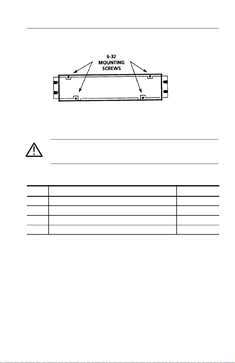
relative ease. The instrument is secured in the cabinet with four 6–32
TORXR drive screws. See Figure 1–1.
1–4
1780R-Series Operator’s Manual
Page 25
Getting Started
Figure 1–1: Location of the four screws that secure the instrument to
rack-mounting cabinet or portable case
WARNING. Do not attempt to carry a cabinetized instrument without
installing the rear -panel mounting screws. There is nothing to hold
the instrument in the cabinet if it is tipped forward.
Table 1–1: Rack-Mounting Hardware Included
Qty Description Part Number
2 Bracket, Extension: 2.5 X 8.06 X 0.06, Steel 407-3752-00
2 Nut Bar: (3) 10-32 X 3.0 X 0.375 X 0.125, Aluminum 381-0251-00
12 Screw, Machine: 10-32 X 0.625, Steel 212-0577-00
4 Washer, Flat: 0.203 ID X 0.625 OD X 0.062, Steel 210-1061-00
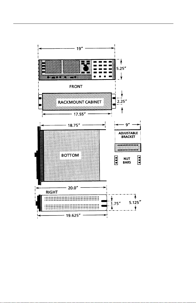
A front clearance of at least 18 inches is required for removing the
instrument from the rack. BNC connectors on the rear panel extend
approximately 0.6 inches, making it necessary to have 1 inch or
more of rear clearance to have enough room to cable the instrument.
See Figure 1–2 for rack-mounting dimensions.
1780R-Series Operator’s Manual
1–5
Page 26
Getting Started
1–6
Figure 1–2: Dimensions used for rack-mounting the 1780R-Series Video
Measurement Set
1780R-Series Operator’s Manual
Page 27
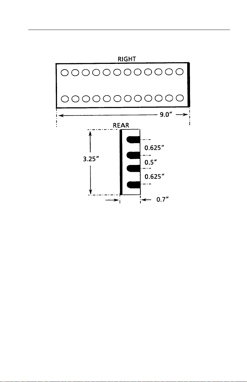
Getting Started
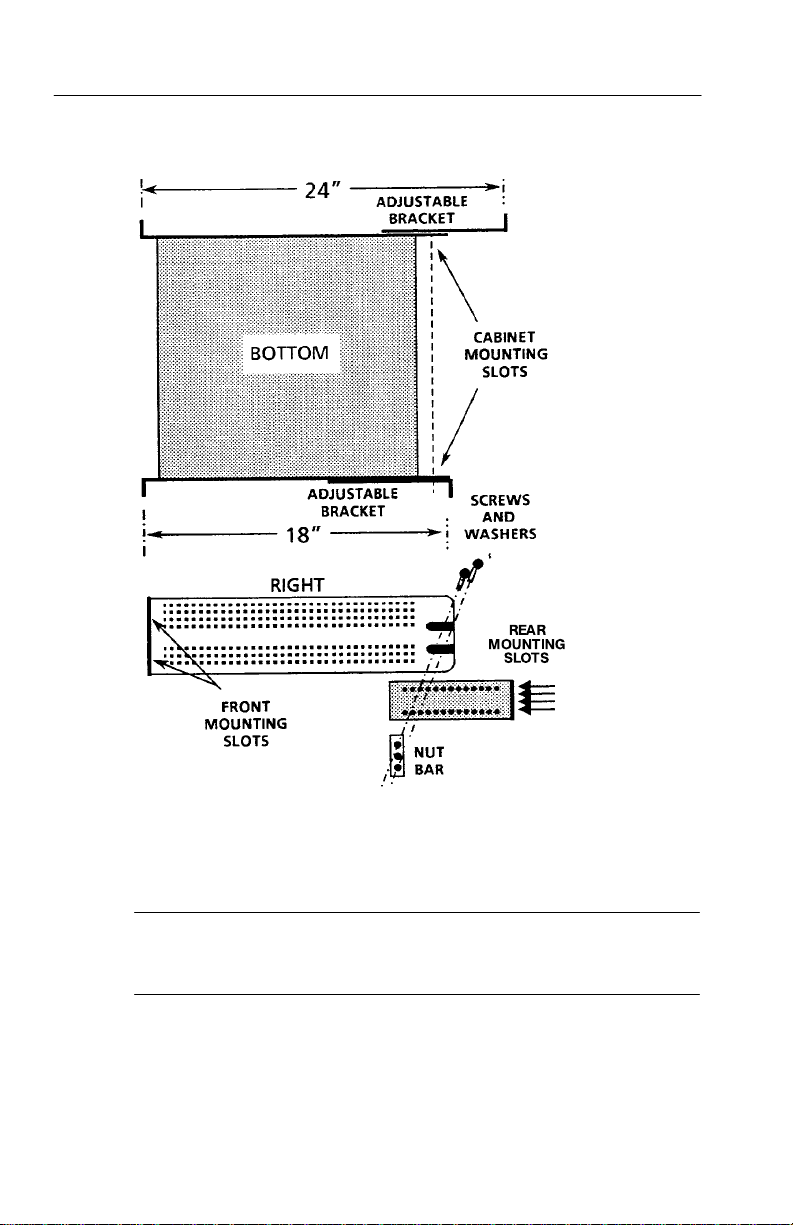
Figure 1–3: Dimensions of the adjustable rear rack-mounting bracket
To install the instrument in the rack: First remove the four securing
screws and take the instrument out of the rack-mounting cabinet.
(All 1780R-Series instruments are shipped in the rack-mounting
cabinet to provide extra shipping protection.) Once the instrument is
out of the cabinet, mount the front of the cabinet in the rack, using
four 10–32 TORXR screws. Cabinet front slots are spaced, and wide
enough, to accommodate standard racks. Next, mount the adjustable
brackets to the rear rack section. See Figure 1–3 for bracket
dimensions. Then mount the adjustable brackets to the rack-mount
cabinet using four 10–32 TORXR screws, four number 10 flat
washers, and the nut bars. See Figure 1–4 for more assembly detail.
Finally , re-install the four 6–32 screws that secure the instrument to
the rack-mounting cabinet. See Figure 1–1.
1780R-Series Operator’s Manual
1–7
Page 28
Getting Started
1–8
Figure 1–4: Installing rear rack-mounting brackets for rack applications
of depths from 18 to 24 inches
NOTE. For ease of installation, place the nut bars to the outside of
the adjustable brackets and drive the screws from the center into the
nut bars.
For applications where it is necessary to rack-mount the instrument,
but have it removable with the instrument case, order the 1780F05
Rack-Mount Shelf.
1780R-Series Operator’s Manual
Page 29

Options
The 1780R-Series is shipped with a standard U.S. plug, or can be
ordered with one of the following options.
Option A1 (220 V, European plug)
Option A2 (240 V, United Kingdom plug)
Option A3 (240 V, Australian plug)
These are the only options currently available for the 1780R-Series.
Part numbers are listed in Section 6.
Standard Accessories
The following accessories are shipped with the 1780R-Series. Part
numbers are listed in Section 6.
1 1780R-Series Operator’s Manual
1 Cable, Power (Standard, Opt A1, A2, or A3)
Getting Started
1 Filter, Air
1 Graticule, 511-1979, Visual (1780R ONLY)
1 Graticule, 511-1979, Photographic (1780R ONLY)
1 Graticule, K-Factor, V isual (1781R ONLY)
1 Graticule, K-Factor, Photographic (1781R ONLY)
3 Graticule Lamp, Incandescent
1 Replacement Cartridge Fuse, 2 A Slow Blow
1780R-Series Operator’s Manual
1–9
Page 30

Getting Started
Optional Accessories
The following is a list of the most common accessory items for the
1780R-Series. Part numbers, if applicable, are listed in Section 6.
1780R-Series Service Manual
Viewing Hood
Portable Cabinet
Extender Kit for Oscillator and Z-Axis Circuit Boards
1–10
1780R-Series Operator’s Manual
Page 31

Connectors, Controls, Indicators Connectors, Controls, Indicators
Page 32

Page 33

Connectors, Controls, Indicators
This section provides an overview of control and connector
functions. T o locate more detailed information, please refer to the
manual index or table of contents.
Switches
Push and release the front-panel switches to toggle between
selections. Push and hold to access outlined selections.
Companion Switches
Some switch functions are paired or grouped so that two or three
switches determine one display. These are referred to in this manual
as companion switches.
Pushing the same companion switch twice in succession will change
its selection (as indicated by the LED).
Pushing first one companion switch and then another will cause the
display to alternate between the first switch selection and the second
switch selection. Held functions will be forced to the top function of
the switch. For example, VECT and SCH together reverts to VECT.
Controls
All front-panel controls are continuous except the Horizontal
Position control, which has stops. It also has a spring return which
returns it to the center position. The further from center the control is
turned, the faster the display moves. This is useful in MAG
operation.
The five CRT controls (Focus, Scale, Intens, VPOS, and HPOS) are
used to adjust both CRTs. Refer to CRT Controls for details.
LEDs
Green LEDs indicate front-panel switch selections. Some LEDs are
located next to the function label, and some are located in the switch
itself.
Red LEDs indicate an uncalibrated gain condition.
1780R-Series Operator’s Manual
2–1
Page 34

Connectors, Controls, Indicators
Audio Feedback (Beep)
A Beep Sounds When:
The limit of a front-panel control range has been reached.
An attempt is made to change a locked setting.
An attempt is made to access an invalid condition, such as a Parade
display in 1-line mode.
Disable the Beep
Selecting Beep Off in the Configure menu will disable the beep for
all cases except touch screen selection.
A “Click” Occurs When:
A touch screen selection is made. (Click cannot be disabled.)
Touch Screen
Both CR Ts are equipped with 4 × 4 (four vertical and four horizontal
divisions) LED matrix touch screens to provide menu access to
additional instrument functions.
2–2
Selections are made by touching the desired function on the CRT
screen.
Instructional labels, such as SELECT MEASUREMENT, are shown
on the CRT screen in italics.
T ouching the CRT screen is indicated in this manual by the use of
the word ‘touch’ (as opposed to ‘push’ for front-panel switches).
A “click” indicates that a touch screen selection has been made.
If two or more choices are available, the current selection will be
outlined on the screen.
If a menu choice is not displayed, nothing will happen when the
screen is touched.
A circle around a menu choice indicates the current assignment of
the large knob.
1780R-Series Operator’s Manual
Page 35

Front-Panel Controls
NOTE. Locations for the following controls are shown in Figure 2–1.
Power
1. POWER. The Power push-button switch turns the instrument on
or to standby status, and displays a colored spot inside the switch
when power is on.
CRT Controls
The five CRT controls (Focus, Scale, Intens, VPOS, and HPOS) are
used to adjust both CRTs. Assignment of these controls from one
CR T to the other is controlled by two illuminated switches, one
under the left CRT and one under the right CRT.
When <TIMEOUT> <ON> is selected (Configure menu, described
in Section 3), vectorscope assignment of CRT controls will revert to
waveform assignment after 30 seconds of no knob activity.
Connectors, Controls, Indicators
The settings of the five CRT controls are saved and restored when
toggling between waveform and vector assignments.
2. Left switch. This switch assigns the Focus, Scale, Intensity, and
Position controls to operate with the left (vectorscope) CRT.
3. Right switch. This switch assigns the Focus, Scale, Intensity, and
Position controls to operate with the right (waveform monitor)
CR T.
4. SCALE. The Scale control adjusts the level of graticule
illumination. A beep indicates the limits of the control range.
5. FOCUS. The Focus control adjusts the beam for optimum
definition. A beep indicates the limits of the control range.
6. INTENS. The Intensity control adjusts display brightness. A beep
indicates the limits of the control range.
1780R-Series Operator’s Manual
2–3
Page 36

Connectors, Controls, Indicators
2–4
Figure 2–1: Left side of front panel
1780R-Series Operator’s Manual
Page 37

Connectors, Controls, Indicators
7. VER T POS. Use the Vertical Position control to move the display
up and down. A beep indicates the limits of the control range.
(Positioning range is greater for waveform monitor than for
vectorscope.)
8. HORIZ POS. Use the Horizontal Position control to move the
display left and right. Below SNs B020245 only, this is a spring
activated control; turn the control more to move the display
faster. A beep indicates the limits of the control range. (Positioning range is greater for waveform monitor than for vectorscope.)
Precision Measurement (Large Knob)
NOTE. Detailed measurement information is located in Section 4.
The TIME and VOLTAGE CURSORS, PHASE SHIFT, and LINE
SELECT switches are enabled by pushing the corresponding switch,
and exited by pushing that switch again.
While any of these modes is enabled, rotating the large knob
provides continuous adjustment, and pushing the < > buttons
provides single-step adjustment.
T wo, three, or all four of these functions can be enabled at once.
Separate readouts are provided for each function. Large knob
assignment is determined by the last function button pushed, and can
be changed by touching the desired readout area of the CRT screen.
Current assignment is circled.
NOTE. Detailed T iming and Voltage Cursor information is located in
Section 3.
9. TIME CURSORS. This switch enables the timing cursors. The
Timing Cursor menu on the vectorscope CRT provides a choice
of cursors that track together or are positioned separately, and a
choice between locate and measure.
The readout indicates the time difference between Cursor One
and Cursor T wo, in increments of 5 nanoseconds. If magnifica-
1780R-Series Operator’s Manual
2–5
Page 38

Connectors, Controls, Indicators
tion or variable sweep is selected, the cursor interval is magnified
correspondingly.
To change the large knob assignment from one cursor to another,
touch the quadrant labeled <CURSOR 1 / CURSOR 2>. The
current assignment is outlined by a box.
Timing cursors are not valid in Field mode.
For software versions 1.13 and up, installed in instruments SN
B020100 and up: Refer to (11) LINE SELECT for information on
Timing Cursors in Line Select mode.
NOTE. Detailed T iming and Voltage Cursor information is located in
Section 3.
10. VOLTAGE CURSORS. This switch enables the voltage cursors.
The Voltage Cursor menu on the vectorscope CRT provides a
choice of cursors that track together or are positioned separately,
and a choice between absolute and relative readout. Cursor One
appears as a dashed horizontal line, and Cursor T wo as a series of
two short dashes on the waveform monitor display. If vertical
gain is employed, the cursor interval is magnified accordingly.
2–6
To change the large knob assignment from one cursor to another,
touch the quadrant labeled <CURSOR 1 / CURSOR 2>. Current
assignment is outlined by a box.
11. LINE SELECT This switch enables the line select function,
which is available for both waveform and vectorscope. For
waveform display, the selected line is displayed first in a multiple
line display , and brightened in a field display. Alpha-numeric
readout indicates the selected line and field on both CRTs.
Additional line select information can be found in Section 3.
Full measurement functions are available in Line Select mode.
Large knob assignment is indicated by a circle, and is selected by
touching the line number area on the desired CRT screen.
1780R-Series Operator’s Manual
Page 39

Connectors, Controls, Indicators
Different lines can be displayed on the waveform and vectorscope CRTs, when that function is selected via the Line Select
menu by touching <WFM = VECT> until <NO> is outlined.
For software versions 1.13 and up, installed in instruments SN
B020100 and up: For ease in viewing the Timing Cursors while
in Line Select mode, the Timing Cursor dots are positioned on
the Voltage Cursors. Upon entering Line Select mode with
Timing Cursors on, the Voltage Cursors are automatically
enabled.
For software versions 1.13 and up: A dual Line Select mode is
available for making ICPM measurements when in Line Select. It
is described in Section 4, under ICPM Measurement.
12. PHASE SHIFT. This switch enables the precision phase shift
measurements. Phase readout appears in the upper left corner of
the vectorscope CRT. This readout changes as the phase is
shifted. For SCH operation, the phase ranges from 180_ to 180_.
For Vector, the configure menu offers a choice of two phase
displays: 180_ to 180_ or 0_ to 360_.
13. REFERENCE SET. This switch is used in Phase Shift, Voltage
Cursor, and Line Select modes. In Phase Shift, it stores the
currently displayed phase as a reference and resets the readout to
0.00. In Voltage Cursor mode with <RELA TIVE> selected, it
stores the currently displayed voltage as a reference and resets
the readout to 100% (0 dB). In Line Select mode, it is used to
access the vertical interval (line 19).
14. KNOB. The Precision Measurement control (large knob) operates
with selected functions to provide continuous adjustment.
15. < > These switches operate with selected functions to provide
single-step adjustment. The readout increments are the same as
those for the Precision Measurement Control.
1780R-Series Operator’s Manual
2–7
Page 40

Connectors, Controls, Indicators
Menu Access Switches
NOTE. Detailed menu information is located in Section 3.
16. PRESET. This switch provides access to the Preset menu screen,
which allows the user to store, recall, and name up to 12
complete instrument setups.
17. MEASURE. This switch provides access to the Measurement
menu screen. Selections, made by touching the screen, are: DIFF
PHASE, DIFF GAIN, DP & DG, NOISE, ICPM, K FACTOR,
CHROMA/LUMA, SHORT TIME DISTORTION, RY SWEEP,
BOWTIE, and FSC TIME MARKS. Measure menu selections,
including user-modified instrument configuration, can be stored
and recalled through the Preset menu. When a preset containing a
measurement mode is recalled, the instrument will automatically
reenter that measurement mode.
18. CONFIGURE. This switch provides access to the Configure
menu. This is a three-page menu; touch <PAGE> to sequence
through the pages. Configure menu settings include units of
measure, probe input, DC restorer, int / ext graticules, 75% /
100% color bars, calibrator amplitude, etc.
2–8
19. CALIBRATE. This switch provides access to the Calibration
menu, which toggles between waveform and vectorscope when
the buttons under the CRTs are pushed. Specified instrument
parameters can be set, using either the internal calibrator signal
or an input signal for reference.
Waveform Calibrate menu selections are: CAL SIGNAL
ON/OFF, VOLT CURSORS ZERO SET, CAL AMPL ZERO
SET , HORIZ POS KNOB CAL, EXT HORIZ CAL, HORIZ
CAL, TRACE ROTATION, READOUT INTENSITY, and VERT
CAL.
Vectorscope Calibrate menu selections are CAL OSC ON/OFF,
TRACE ROTATION, READOUT INTENSITY , and GAIN CAL.
1780R-Series Operator’s Manual
Page 41

Connectors, Controls, Indicators
Probe
20. BNC Connector. This is the input connector for a X1 or X10
probe.
21. CAL OUT. This pin jack outputs the calibration signal used to
compensate the X10 probe. DC Restorer must be OFF (page 1 of
the Configure menu) and EXT REF must be selected.
Display Mode
Companion Switches. Some switch functions are paired or grouped so
that two or three switches determine one display. These are referred
to in this manual as companion switches.
Pushing the same companion switch twice in succession will change
its selection (as indicated by the LED).
A Held mode will be exited when its companion switch is pushed,
and then the HELD switch is (momentarily) pushed again. The
switch setting will revert to the last selection before the Held mode
was entered.
Pushing first one companion switch and then another will cause the
display to alternate between the first switch selection and the second
switch selection.
NOTE. Some switches may be locked out by menu selections.
Companion Switch Example. VECT / SCH and XY / PIX are used to
select vectorscope CRT displays.
Push and release the VECT/SCH switch to select Vector. It will
require one or two pushes.
Now push and release the XY / PIX switch to select XY.
Push the VECT / SCH switch. Note that it is restored to Vector.
Push the XY / PIX switch. Note that it is restored to XY.
Push the XY / PIX switch a second time. Now it toggles to PIX.
Push the VECT / SCH switch twice. Now it toggles to SCH.
1780R-Series Operator’s Manual
2–9
Page 42

Connectors, Controls, Indicators
Figure 2–2: Right side of front panel
2–10
1780R-Series Operator’s Manual
Page 43

Connectors, Controls, Indicators
N
ess beep s
r
Waveform mode
N
ess
bee
s
ds
If
ON
INsseeed
O
er
r
Wefrmmdesr
mereer
s
NOTE. The following switch groups are companion switches:
VECT / SCH & XY / PIX, PARADE / OVERLAY & WAVEFORM/
WFM + CAL.
Refer to the preceding instructions entitled Companion Switch
Example. Locations of the switches are shown in Figure 2–2.
22. VECT / SCH. Push and release this switch to toggle between
Vector and SCH phase display for the vectorscope CRT. Push and
hold to access SCH phase and Vector together.
23. XY / PIX. Push and release this switch to toggle between XY and
Picture Monitor display for the vectorscope CRT. Push and hold
to add XY to the current VECT / SCH selection. Push and release
to exit held mode.
24. PARADE / OVERLAY. Push and release this switch to toggle
between Parade and Overlay modes. Possible configurations are
shown in T able 2–1.
Table 2–1: Possible Parade and Overlay Configurations
Display Possible Inputs * Automatic Selections
Parade
ONE LINE
TWO LINE CH A and Probe, or
THREE LINE CH B1 and CH B2 and
1780R-Series Operator’s Manual
o acc
CH B1 and Probe, or
CH A and CH B1, or
CH B1 – CH B2 and
CH B1 – CH B3 (Bowtie)
CH B3
ounds.If ONE LINE is selected in Overlay o
, instrument reverts to
TWO LINE or THREE LINE when
Parade is selected.
If CH B1, CH B2, and CH B3 are
selected, the instrument will revert to
THREE LINE mode.
If any combination of two input
channels is selected, the instrument
will revert to TWO LINE mode.
2–11
Page 44
C
d
C
2
r
If
TWO
INrT
R
IN
er
-
C
d
C
3
r
ssee
edsr
me
re
er
Connectors, Controls, Indicators
C
r
If TWO LIN
-
C
r
Table 2–1: Possible Parade and Overlay Configurations (Cont.)
Display Automatic SelectionsPossible Inputs *
Overlay
ONE LINE or
FIELD
H B1 and CH B2, o
H B1 and CH B3, o
CH B2 and CH B3, or
CH A and Probe, or
Probe and CH B1, or
CH A and CH B1, or
CH B1 and CH B2 and
CH B3
E or THREE LINE opera
tion is selected, instrument will revert
to ONE LINE or FIELD operation
when Overlay is selected.
* Other combinations not permitted, and will cause a beep to sound.
25. WFM / WFM+CAL. Push and release this switch to toggle
between standard waveform display and waveform plus calibrator
signal.
Ref
26. INT / EXT / CW . This switch toggles between an internal signal
(incoming video) and an external signal (rear-panel input) for
sync and subcarrier reference. Push and hold this switch to select
the rear-panel CW input as a subcarrier reference. The LED will
indicate whether CW Sync has been set for internal or external
(via the Configure menu, page 3).
27. LINE / FIELD. Push and release to toggle between LINE and
FIELD. Line and Field combinations are limited only when in
Overlay and Parade modes. See T able 2–1.
2–12
Wfm Horizontal
28. ONE / TWO / THREE. Push and release to toggle between ONE
and TWO. Push and hold to select THREE. The Line and Field
combinations are limited only when in Parade or Overlay mode,
as shown in T able 2–1.
Magnifier
29. ON >. Push and release to turn on the magnifier, then push again
to increase magnification. Push and hold to turn on the magnifier
1780R-Series Operator’s Manual
Page 45

and continuously increase the magnification factor. Magnifica-
>
tton
Magnification
>
tton
Magni
ication
tion factors are shown in T able 2–2.
Table 2–2: Waveform Magnification
Connectors, Controls, Indicators
Bu
Setting
Off X1
One Push X5
Two Pushes X10
Three Pushes X20
Four Pushes X25
Five Pushes X50
Six Pushes X100
Factor
30. OFF <. Push and release to decrease magnification (up to six
steps). Turns off the magnifier when pushed enough times, or
when held.
31. VAR / SLOW (Switch). This switch toggles between V ariable
Sweep, Slow Sweep, and Off (calibrated sweep).
32. SWEEP RATE (Control). Use the knob to control the sweep rate
when VAR is selected, and sweep duration when SLOW is
selected. VAR and SLOW control settings are saved and
reinstated each time the mode is entered. T o return to calibrated
sweep, push the VAR/SLOW button until the red LEDs are off.
msec/Div
1 Line 2 Line 3 Line
5.0 ms 10.0 ms 15.0 ms
1.0 ms 2.0 ms 3.0 ms
0.50 ms 1.0 ms 1.50 ms
0.25 ms 0.50 ms 0.75 ms
0.20 ms 0.40 ms 0.60 ms
0.10 ms 0. 20 ms 0.30 ms
0.05 ms 0.10 ms 0.15 ms
Gain
33. VAR / X5 (Switch). This switch controls the waveform monitor
vertical gain. Push and release to toggle through variable gain,
X5 gain, and off. The waveform knob controls the amount of
variable gain when VAR is selected. Push and hold to enable both
X5 and Variable Gain.
1780R-Series Operator’s Manual
2–13
Page 46

Connectors, Controls, Indicators
34. WAVEFORM (Control). Use this knob to control the amount of
variable gain when VAR is selected.
35. VECTOR (Control). Use this knob to control the amount of
variable gain when VAR is selected.
36. VAR / MAX (Switch). Push and release this switch to turn on the
vectorscope variable gain, which is controlled by the Vector
knob. Push and hold to disable the variable and set the vectorscope gains to maximum.
Filter
NOTE. The following switch groups are companion switches: AUX /
DIFF / LPASS & FLAT / LUM / CHROM
Refer to the preceding instructions entitled Companion Switch
Example.
37. AUX / DIFF / LPASS. Push and release this switch to toggle
through the following selections: Aux Video In (signal is input
after the video filters), Differentiated step (linearity steps are
translated into spikes for amplitude comparisons), and Low-pass
filter (300 kHz bandwidth).
38. FLAT / LUM / CHROM. Push and release this switch to toggle
through the following selections: Flat (unfiltered video signal),
Luminance (chrominance filtered out), and Chrominance
(luminance filtered out). Push and hold to select a multiple filter
display , described in Table 2–3.
Table 2–3: Multiple Filter Displays
Display Possible Switch Settings
ONE LINE or FIELD Flat/Lum overlay.
TWO LINE or FIELD Flat filtered displayed first (left portion of screen), then
luminance filtered.
THREE LINE or FIELD Flat filtered displayed first, followed by luminance filtered
and chrominance filtered.
2–14
1780R-Series Operator’s Manual
Page 47
Connectors, Controls, Indicators
T
T
C
er
T
T
esbeee
2
esd
3
e
s
T
es
se
e
e
e
C
C
2dC
3
e
er
T
es
se
e
e
e
NOTE. The three INPUT switches are companion switches. Refer to
the preceding Companion Switch Example.
Input
39. A–B1 / B1–B2 / B1–B3. This switch selects from the following
inputs for display: CH A minus CH B1, CH B1 minus CH B2, or
CH B1 minus CH B3. Push and hold this switch to select CH B1
minus CH B2 and CH B1 minus CH B3 together (Bowtie).
Instrument will be forced to 2-Line Parade operation.
40. CH B1 / CH B2 / CH B3. In WFM mode, push and release this
switch to select the rear-panel Channel B1, Channel B2, or
Channel B3 input for display on both CRTs. In Parade mode, all
three are forced on. In Overlay, it selects any two or all three
input channels on. Refer to T able 2–4 for an outline of possible
switch settings.
Table 2–4: Possible CH B1, CH B2, CH B3 Switch Settings
Display Possible Switch Settings
Overlay
ONE LINE or FIELD
Waveform
TWO LINE or FIELD
Parade
THREE LINE or FIELD
Waveform
THREE LINE or FIELD
(Push & Hold)
oggles between 2 channels and all 3 channels on.
oggles to select any one channel.
H B1, CH B2, and CH B3 on togeth
oggles to select any one channel.
41. CH A / PROBE. This switch selects the rear-panel Channel A
input or the front-panel Probe input for display on both CRTs.
Upon entering the Probe mode, the following message appears:
“PROBE– – 50V DC MAX.”
1780R-Series Operator’s Manual
2–15
Page 48

Connectors, Controls, Indicators
Rear Panel Connectors
Connectors CH A, CH B1, CH B2, CH B3, EXT REF, and CW are
high impedance bridging loop-through inputs. CH A, CH B1,
CH B2, and CH B3 have either a grounded or floating shield,
depending on the position of the grounding screw, which is located
between the BNC connectors.
The following connector locations are shown in Figure 2–3.
1. CH A. CH A accepts composite or component video signals.
2. CH B1. CH B1 accepts composite or component video signals.
3. CH B2. CH B2 accepts composite or component video signals.
4. CH B3. CH B3 accepts composite or component video signals.
5. XY INPUT. XY is a 15-pin D-type connector used as a high
impedance input for the 600 W balanced audio. XY operation is
described in Section 3. The connector pinout is shown in Figure
3–5 on page 3–11.
6. EXT CW REF. CW connector accepts input for continuous
subcarrier signal. Provides an external phase reference signal.
2–16
7. LINE STRB OUT. LINE STRB OUT is a TTL output that
provides a negative-going pulse for the selected line(s) when
Line Select is used. When Line Select is off, the output level is
low.
8. AUX OUT. AUX OUT provides a 75 W video signal output
before filtering. AUX OUT can be used with the AUX IN to use
custom filters.
9. PIX MON OUT. PIX MON OUT connector provides a 75 W
output to drive a picture monitor. The signal is output before
filtering, and has a bright-up pulse added when Line Select is
used.
10. AUX IN. AUX IN provides a 75 W input for video signals to the
waveform monitor. Signal is inserted after the internal filters.
11. EXT REF . External Reference connector accepts either
composite sync or black burst.
1780R-Series Operator’s Manual
Page 49

Connectors, Controls, Indicators
Figure 2–3: Rear-Panel Connectors
1780R-Series Operator’s Manual
2–17
Page 50

Connectors, Controls, Indicators
12. EXT HORIZ. The EXT HORIZ input connector allows external
control of waveform monitor sweeps. A positive-going signal
deflects the sweep from left to right. A 0 V to +5 V signal is
required for full scale deflection (ICPM).
13. SERIAL PORT. This 9-pin D-type connector provides a serial
remote control interface, compatible with both RS232 and RS422
standards. Serial Port communications are described in Section 3.
The connector pinout is shown in Figure 3–9 on page 3–18.
14. REMOTE. This 15-pin D-type connector provides a ground
closure remote control interface and signal inputs for Remote
Sync and RGB/YRGB. Remote operation is described in
Section 3. The connector pinout is shown in Figure 3–8 on
page 3–15.
2–18
1780R-Series Operator’s Manual
Page 51

Operating Instructions Operating Instructions
Page 52

Page 53

Operating Instructions
Large Knob And Associated Switches
Timing Cursors
Push the TIME switch to enable the timing cursors and obtain a
menu on the vectorscope CRT. Use this menu to choose cursors that
track together or are positioned separately, and to choose between
locate and measure.
When <SEPARATE> is selected by touching the <SEPARATE/
TRACK> area of the screen, the large knob moves Cursor One or
Cursor T wo, depending on which cursor is selected (outlined). When
<TRACK> is selected, the large knob moves both cursors at the
same time.
The two cursors appear as bright-up portions of the waveform
display when <LOCATE> is selected, or as bright-up dots when
<MEASURE> is selected. The readout indicates the time difference
between Cursor One and Cursor T wo, in five nanosecond intervals.
If magnification or variable sweep is selected, the cursor interval is
magnified correspondingly. Time difference between Cursor One and
Cursor T wo can be determined, even though they may not both be on
screen at the same time.
To change the large knob assignment from one cursor to another,
touch the quadrant labeled <CURSOR 1 / CURSOR 2>. The current
assignment is outlined by a box.
Cursors appear to “wrap around” in One Line and T wo Line sweeps
because the total cursor range (160 ms) extends beyond the One or
T wo Line sweep length. A beep sounds at both ends of the range.
Time difference between Cursor One and Cursor Two can be
determined, even though they may not both be on screen at the same
time.
Pushing REFERENCE SET has no effect while Timing cursors are
enabled.
Timing cursors are not valid in Field modes.
1780R-Series Operator’s Manual
3–1
Page 54

Operating Instructions
For software versions 1.13 and up, installed in instruments SN
B020100 and up: The Timing Cursor dots are positioned on the
Voltage Cursors while in Line Select mode, for ease in viewing the
Timing Cursors.
Voltage Cursors
Push the VOLTAGE switch to enable the voltage cursors and obtain
a menu on the vectorscope CRT. Use this menu to choose cursors
that track together or are positioned separately, and to choose
between absolute and relative readout.
Cursor One appears as a dashed horizontal line, and Cursor T wo as a
series of two short dashes on the waveform monitor display.
The large knob provides continuous adjustment of cursors. The < >
buttons provide adjustment in discrete steps of 0.1 IRE or 1mV
(depending on the Configure menu ABS UNITS selection).
To change the large knob assignment from one cursor to another,
touch the quadrant labeled <CURSOR 1 / CURSOR 2>. The current
assignment is outlined by a box.
When <SEPARATE> is selected by touching the <SEPARATE /
TRACK> area of the screen, the cursors are moved one at a time
(currently selected cursor is outlined). When <TRACK> is selected,
both cursors move at once.
3–2
When <ABSOLUTE> is selected, the readout (in IRE or mV)
indicates the voltage difference between the two cursors. The mV /
IRE selection is made through page 2 of the Configure menu. The
Configure menu instructions appear later in this section.
REFERENCE SET has no effect in Absolute mode.
When <RELATIVE> is selected, the readout is shown in percent and
dB, relative to the value when REFERENCE SET was last pushed.
REFERENCE SET resets the relative value to 100.0% (0 dB).
If vertical gain is employed, the cursor interval is magnified
correspondingly. Voltage difference between Cursor One and Cursor
T wo can be determined, even though they may not both be on screen
at the same time.
1780R-Series Operator’s Manual
Page 55

Operating Instructions
For software versions 1.13 and up, installed in instruments
SN B020100 and up: Voltage cursors are automatically enabled when
in Line Select with Timing Cursors.
Line Select
This switch enables the line select function, which is available for
both waveform and vectorscope. For waveform display, the selected
line is displayed first in a multiple line display, and brightened in a
field display. Alpha-numeric readout indicates the selected line and
field on both CRTs.
In software versions 1.11 and up, a 1 of 8 Field reference is
provided, for use with ghost-cancelling signals. In NTSC, the 8 Field
reference is built from two groups of 4 Fields. T ouching <ALT
FIELD> will toggle between the two groups as a starting point for
the 8 Field reference.
When 2 of 4 Field reference is selected, the <FIELD> area in the
lower right corner of the screen will toggle between Fields 1 and 3 or
Fields 2 and 4; when 1 of 4 is chosen, it will allow selection of Field
1, 2, 3, or 4; and when 1 of 8 (present in software versions 1.11 and
up) is chosen, it will allow selection of Field 1, 2, 3, 4, 5, 6, 7, or 8.
The selected field or field pair is boxed. When <ALL> Fields is
selected, the <FIELD> area is no longer present in the lower right
corner of the screen, and all fields are overlaid.
To enable the Line Select menu, first push the LINE SELECT
front-panel button, then touch <LSEL MENU> on the vectorscope
CR T until <ON> is outlined. To exit the menu, push the same area
again until <OFF> is outlined.
Line Select menu choices are shown in Figures 3–1 and 3–2. T ouch
desired area to toggle between choices. Current selection is outlined
by a box.
T ouch <VECT 1H/15H> or <WFM 1H/15H> to display the selected
line (<1H>) or display the selected line plus the next 14 overlaid
(<15 H>).
1780R-Series Operator’s Manual
3–3
Page 56

Operating Instructions
Figure 3–1: Line Select Menu Screen with <2 OF 4> Fields selected
3–4
The waveform and vectorscope CRTs can be used to display the
same selected line or different lines. To display different lines,
enable the Line Select menu, then touch <WFM = VECT> until
<NO> is outlined. Be sure that both <VECT LSEL> and <WFM
LSEL> show <ON> outlined. T ouch <LINESEL MENU> again, so
that <OFF> is outlined and the menu is no longer displayed on the
vectorscope CRT.
When different lines are displayed on waveform and vectorscope
CR Ts, touch the line number area on the desired CRT to change the
large knob assignment. This assignment is indicated by a circle.
T o display the same line on both CRTs, select <WFM = VECT> and
<YES>. The line number will be circled on both CRTs.
1780R-Series Operator’s Manual
Page 57

Operating Instructions
Figure 3–2: Line Select Menu Screen with <1 OF 8> Fields selected
For software versions 1.13 and up: A dual Line Select mode is
available for making ICPM measurements when in Line Select. It is
described in Section 4, under ICPM Measurement.
Phase Shift
This switch enables precision phase shift measurements. Phase
readout appears in the upper left-hand corner of the vectorscope
CR T.
This readout changes as the phase is shifted, indicating the degrees
of change since the phase reference was set.
Reference Set
This switch is used in Phase Shift mode, to store displayed phase as a
reference and reset the readout to 0.00; in Voltage Cursor mode with
<RELATIVE> selected, to store the displayed voltage as a reference
and reset the readout to 100%; and in Line Select mode to access the
vertical interval (line 19).
1780R-Series Operator’s Manual
3–5
Page 58

Operating Instructions
Knob
The Precision Measurement control (large knob) provides analog
precision adjustments associated with the REFERENCE SET , LINE
SELECT , PHASE, TIMING CURSOR, and VOLTAGE CURSOR
switches, or as assigned by menu selections.
The current function of this knob is circled on the CRT screen.
< > Switches
The < > switches provide single-step increments. The readout
increments are the same as those for the Precision Measurement
Control readout. Push and release for an individual increment, or
push and hold to continue increments.
Graticules
This section describes the basic vector and waveform graticule
markings for both the 1780R (NTSC), and 1781R (PAL) instruments.
Scale Illumination for Vector and Waveform Graticules
The choice of internal or external graticule illumination is provided
on page 2 of the Configure menu. Refer to the Configure menu
instructions in this section. T o adjust scale illumination, push the
button under the vectorscope or waveform CRT (to assign CRT
controls to vectorscope or waveform), then adjust the SCALE
control as desired.
3–6
Using The Vector Graticule
Basic Vector Graticule Markings. The NTSC Vector graticule is shown
in Figure 3–3. The polar display permits measurements of hue in
terms of the relative phase of the chrominance signal with respect to
the color burst. Relative amplitude of chrominance to burst is
expressed in terms of the displacement from center (radial dimension
of amplitude) towards the color point which corresponds to 75% (or
100%) amplitude for the color being measured.
1780R-Series Operator’s Manual
Page 59

Operating Instructions
Figure 3–3: 1780R Vector Graticule
The graticule includes four burst amplitude marks: 75% with setup,
75% with no setup, 100% with setup, and 100% with no setup.
On the NTSC graticule, each chrominance vector terminates in a
system of graticule targets in the form of two boxes (a small box
inside a large box). The dimensions of the large boxes represent
±10_ centered on the exact chrominance phase, and ±20% of
chrominance amplitude centered around 100% of standard
amplitude. The dimensions of the smaller boxes represent ±2.5_ and
±2.5 IRE.
The PAL Vector graticule is shown in Figure 3–4. On the PAL
graticule, each chrominance vector related to the +V burst terminates
in targets that are in the shape of two boxes (a small box inside a
large box). The dimensions of the large box represent ±10_ centered
on the exact chrominance phase and ±20% of chrominance
1780R-Series Operator’s Manual
3–7
Page 60

Operating Instructions
amplitude centered around 100% standard amplitude. The dimensions of the smaller inner target represent ±3_ and ±5% of chrominance amplitude. Note that the chrominance vectors associated with
the –V burst are terminated in the smaller targets only.
3–8
Figure 3–4: 1781R Vector Graticule
On the NTSC graticule, the small marks at intervals along the I and
Q axes denote the amplitudes of the chrominance components. On
the PAL graticule, the small marks at intervals along the U and V
axes denote the amplitudes of the U and V chrominance components.
The horizontal and vertical axes of the vector graticule contain
markings for checking Vector mode bandwidth. A subcarrier
frequency sine wave whose amplitude places it on the outer compass
rose is used as a reference. When the frequency is changed, the
diameter of the circle should reduce. At a point equal to 70% of full
1780R-Series Operator’s Manual
Page 61

Operating Instructions
amplitude (3 dB), there are gaps in the horizontal and vertical axes.
This calibration aid makes it possible to check the –3 dB points of
the demodulator output amplifiers.
Differential Gain and Phase Measurements. The 1780R-Series provides
differential gain and phase measurements through the Measurement
menu, accessed by pushing the front-panel MEASURE button.
Instructions are given in Section 4.
The 1780R-Series vector graticule is the same as the 1720-Series
vector graticule, and provides differential gain and phase markings,
so that approximate 1780R-Series measurements can also be made in
the same way as with the 1720. Differential gain (dG) and differential phase (dF) measurements can be made using the graticule
markings located at the outer edge of the B–Y axis (NTSC) or U axis
(PAL).
Differential gain appears as an elongation of the chrominance dot.
Measure the horizontal distance from end to end. Minor graticule
divisions represent 5% error, and major divisions represent 10%.
Differential Phase appears as a vectorial offset of the chrominance
dot. Measure angular difference, using the Differential Phase
graticule markings along the edge of the compass rose. Measuring
from the 0_ mark on the B–Y or U axis, each minor division
represents 2_ of error, the major divisions represent 10_, and the
dashed lines half-way in between represent 5_ of Differential Phase
error.
XY Measurements. The 1780R-Series vectorscope graticule contains
markings for measuring stereo audio phase and amplitude. The
dashed diagonal line is the measurement axis for errors less than
90_, and is terminated in amplitude targets that correspond to the
length of the X and Y axes. These target boxes, in the upper right
and lower left of the display, correspond to amplitude errors of 1/2
and 1 dB.
The upper half of the Y axis has markings in 10_ increments for
measuring the separation of the Lissajous. Both X and Y axes have
–3 dB markings, making it easy to check the bandpass of the
amplifiers. The 3 dB points are minor breaks in the line about 30%
of the distance from the graticule circle to the graticule center.
1780R-Series Operator’s Manual
3–9
Page 62

Operating Instructions
XY INPUT Connector. The rear-panel XY INPUT connector is a 15-pin,
sub-miniature, D-type connector that provides input to the
Horizontal and Vertical (X and Y) Amplifiers. They are balanced
(differential), DC-coupled, high impedance (>20 kW), un-terminated
inputs provided for audio applications. If AC coupling is desired,
external capacitors are required. These inputs are factory calibrated
for 0 dBm in 600 W but can be adjusted for any 600 W system
between 0 and 12 dBm. See Figure 3–5.
0 dBm is equal to 1 mW or 2.19 V peak-to-peak in 600 W. 12 dBm is
equal to 15.8 mW or 8.72 V peak-to-peak in 600 W.
T o calibrate the 1780R-Series for a system other than 0 dBm,
perform step 38 of the Adjustment Procedure in the 1780R-Series
Service Manual, using a 1 kHz sine wave of the appropriate
amplitude.
Inputs can be driven single-ended by driving either the + or – X and
Y inputs with the opposite polarity inputs grounded.
In addition, a single-ended, high-gain mode can be used for other,
primarily non-audio, applications. It can be accessed by installing
plug jumpers on J108 and J205 (on the Vectorscope board, see
T able 3–1) and inputting the signal on the +X and +Y inputs with the
–X and –Y inputs grounded.
3–10
Table 3–1: Plug Jumpers for Vectorscope Board
Jumper
Number
J108 X Input Gain
J205 Y Input Gain
{
Name Plug Position Purpose
Removed {
Installed
Removed {
Installed
Factory installed position.
1780R-Series Operator’s Manual
X gain is normal
X gain is in High Gain
position
Y gain is normal
Y gain is in High Gain
position
Page 63

Operating Instructions
Pin Number Function
1 –X Input
2 No Connection
3 +X Input
4 No Connection
5 –Y Input
6 No Connection
7 +Y Input
8 No Connection
9 –X Input
10 Ground
11 +X High Gain Input
12 Ground
13 –Y Input
14 No Connection
15 +Y High Gain Input
15
8
9
1
Figure 3–5: Rear-panel X–Y Connector Pin Assignments
1780R-Series Operator’s Manual
3–11
Page 64

Operating Instructions
Using The Waveform Graticule
Basic Waveform Graticule Markings. The two basic 1780R-Series
internal waveform graticules are the NTSC and PAL graticules. The
NTSC graticule is shown in Figure 3–6, and the PAL graticule is
shown in Figure 3–7. External graticules (short time distortion for
NTSC and CCIR / K-factor for PAL) are also available in full scale
and in a 3% reduced photo version.
3–12
Figure 3–6: 1780R Waveform Graticule
1780R-Series Operator’s Manual
Page 65

Operating Instructions
Figure 3–7: 1781R Waveform Graticule
Graticule horizontal scales are divided into 12.7 divisions along the
horizontal line at blanking level. The vertical graduations are scaled
according to measuring units and ranges unique to each system – mV
for the CCIR graticule, and IRE units and percent modulation for
NTSC. A mV scale has been added to the NTSC graticule to
facilitate component measurements. The graticules are also marked
for K-factor tolerances and linear-distortion measurements.
Line-time distortion-NTSC. Line-time distortion is measured using the
graticule box labeled L.D. = 2%, 5%. Any test signal that contains
an 18 ms, 100 IRE bar can be used. T o make a measurement, select a
one-line sweep and use the two arrows on the 50 IRE line to position
the bar horizontally. Make sure that the blanking level of the
waveform is on the baseline, and that the bar top passes through
100 IRE at its midpoint. (It may be necessary to use the variable gain
control to normalize the gain.) The box excludes the first and last ms
1780R-Series Operator’s Manual
3–13
Page 66

Operating Instructions
of the bar. Use the ±2% and ±5% graticule marks to quantify the
peak-to-peak deviation of the bar top (tilt or rounding) within the
structure. The vertical gain can be increased to measure small errors.
(When the X5 setting is selected, the graticule marks correspond to
±0.4% and ±1%.)
Line-time distortion measurements can also be made using the
voltage cursors in the RELATIVE mode. Define the amplitude
difference between blanking level and the bar center as 100%. Now
move both of the cursors to measure the peak-to-peak tilt. This
number is the line-time distortion. Remember to ignore the first and
last ms of the bar. The time cursors can be used to locate the
appropriate time interval in the center of the bar. Set the time
separation to 16 ms, and put the time cursors in the TRACK mode.
Move the two cursors together until they are centered on the bar.
Line-time distortion-PAL. Line-time distortion in PAL systems is
measured with a signal that contains a 10 ms or 25 ms white bar. The
measurement methods given here quote the maximum departure of
the bar top from the level at the center of the line bar as the amount
of distortion, but they can be adapted for peak-to-peak measurements. T o make a measurement, measure the maximum deviation
from the center of the bar, and express that number as a percentage
of the level at bar center. The variable gain can be used to normalize
the center of the bar to 500 or 1000 mV. Deviations in the top of the
bar can then be read directly off the graticule in percent. Ignore the
first and last ms of the bar.
Line-time distortion measurements can also be made using the
voltage cursors in the RELATIVE mode. Define the amplitude
difference between blanking level and the bar center as 100%. Leave
one cursor at the bar center, and move the other cursor to measure
the peak positive and peak negative deviations in the top of the bar.
The largest of these numbers (ignore the sign) is the amount of
line-time distortion. The time cursors can be used to locate the
appropriate time interval in the center of the bar. Set the time
separation to the bar time (usually 10 ms or 25 ms) minus 2 ms. Put
the time cursors in the TRACK mode, and move the two cursors
together until they are centered on the bar.
3–14
1780R-Series Operator’s Manual
Page 67

Remote Operation
REMOTE Connector
The rear-panel REMOTE connector is a subminiature 15-pin D-type
receptacle with female contacts. All the active Remote control lines
are enabled by remote ground closures or TTL levels (0 V to
+0.8 V). Pin assignments for the REMOTE connector are shown in
Figure 3–8 and T able 3–2. The REMOTE connector appears in the
1780R-Series Service Manual, Section 11, UART and A/D
Schematic Diagram.
Operating Instructions
Figure 3–8: REMOTE Connector Pin Assignments
Remote Operation
1. Connect the mating male plug supplied with the instrument to a
remote-box cable.
2. Remote lines named Presets 1 through 8 correspond to the
front-panel Preset menu Presets 1 through 8. These remote lines
allow configurations already stored at Presets 1 through 8 to be
recalled, and new configurations to be stored at those preset
locations.
1780R-Series Operator’s Manual
3–15
Page 68

Operating Instructions
a. To recall a preset, force the corresponding remote line
low.
b. To store a front-panel configuration at a preset location,
apply a low first to the Store line (pin 11) and then to the
desired preset. Alternately, the Store line and desired
preset line may be forced low simultaneously.
Table 3–2: Remote Pin Functions
Pin Name Function
1 RGB Staircase Input
2 / RGB Enable Low = RGB Enable. Routes the signal on pin 1 to the
3 NC
4 / Remote Sync Enable Low = Remote Sync Enable. INT / EXT Reference
5 / Preset 2 Low with Pin 11 High = Recall Preset 2.
6 / Preset 3 Low with Pin 11 High = Recall Preset 3.
7 / Preset 1 Low with Pin 11 High = Recall Preset 1.
8 / Preset 4 Low with Pin 11 High = Recall Preset 4.
1 MW input impedance to ground. Requires 10 V
staircase signal.
Horizontal amplifier, where it is added to the ramps
from the Ramp Generator.
In RGB mode, the Ramp Generator reduces the
ramp to 1/3 or 1/4 size (selected by A2J585).
turned off, and instrument sync provided by the
signal on pin 10.
Low with Pin 11 Low = Store current F/P settings at
Preset 2 location.
Low with Pin 11 Low = Store current F/P settings at
Preset 3 location.
Low with Pin 11 Low = Store current F/P settings at
Preset 1 location.
3–16
Low with Pin 11 Low = Store current F/P settings at
Preset 4 location.
1780R-Series Operator’s Manual
Page 69

Operating Instructions
Table 3–2: Remote Pin Functions (Cont.)
Pin FunctionName
9 Ground
10 Remote Sync Input
11 / Store Low = Store.
12 / Preset 8 Low with Pin 11 High = Recall Preset 8.
13 / Preset 5 Low with Pin 11 High = Recall Preset 5.
14 / Preset 6 Low with Pin 11 High = Recall Preset 6.
15 / Preset 7 Low with Pin 11 High = Recall Preset 7.
5 kW input impedance to ground. Polarity set by
jumper A2J192. Factory set for positive polarity.
Used with pin 5, 6, 7, 8, 12, 13, 14, or 15.
Low with Pin 11 Low = Store current F/P settings at
Preset 8 location.
Low with Pin 11 Low = Store current F/P settings at
Preset 5 location.
Low with Pin 11 Low = Store current F/P settings at
Preset 6 location.
3. All front-panel controls operate in their usual manner during
remote operation, so remote selections may be changed with the
front-panel controls.
a. For a remote selection to be effective once it has been
deselected with the front-panel control, it is either selected
again with the front-panel control, or the ground closure is
removed and reattached.
b. Front-panel LED indicators light to show the current
selection.
1780R-Series Operator’s Manual
Low with Pin 11 Low = Store current F/P settings at
Preset 7 location.
3–17
Page 70

Operating Instructions
Serial Communications Interface
Serial Interface Connector
The rear-panel SERIAL interface connector is a 9-pin, sub-miniature, D-type connector. It is used as an RS422A or RS232D interface
to the 1780R-Series microcontroller. Drivers for both interfaces are
resident. RS422A is a balanced voltage digital interface, and
RS232D is a serial binary data interchange. Figure 3–9 shows the
rear-panel SERIAL connector pin assignments.
3–18
Figure 3–9: Serial Interface Connector Pin Assignments
Building a Wiring Converter
Wiring converters can be built to connect the 1780R-Series 9-pin
SERIAL port with another 9-pin connector or with a 25-pin
connector. The 25-pin converter uses a 9-pin male connector
(Tektronix P/N 131-1007-00) and a 25-pin female connector
(Tektronix P/N 131-0971-00), as illustrated in Figure 3–10.
1780R-Series Operator’s Manual
Page 71

9-Pin Male Connector
Operating Instructions
Figure 3–10: Serial Interface Connector Wiring Converter
Serial Remote Information
1780R-Series instrument configurations can be stored at (and
retrieved from) a remote location. T o accomplish this, the 1780R-Series is connected to a host computer through a serial port that
supports RS-232 or RS-422 standards.
All front-panel controls operate in their usual manner during remote
operation, so remote selections may be changed with the front-panel
controls. Front-panel LED indicators light to show the current
selection.
Commands to the 1780R-Series and its responses are listed in T ables
3–3 and 3–4.
1780R-Series Operator’s Manual
3–19
Page 72

Operating Instructions
Table 3–3: Serial Remote Commands to the 1780R-Series
Command* Function Results
#U or #u UPLOAD 1780R-Series sends a stream of data, representing
the current instrument configuration, to the host
computer.
#D or #d DOWNLOAD 1780R-Series expects a stream of data representing
an instrument configuration of the same form that was
uploaded.
#P or #p PARTIAL
DOWNLOAD
1780R-Series expects a stream of data representing
an instrument configuration, with the knob settings
(focus, intensity, etc.) not affected.
* The # character indicates a remote control command. The 1780R-Series
ignores all transmissions until this character is received.
Table 3–4: 1780R-Series Responses
Command Description
A The transmission was successful (ACK)
C Command not known. (The # character was received, but was not followed
by a U, u, D, d, P, or p. )
D Bad data received (all expected data consists of ASCII printable
characters.)
H Bad internal checksum.
N Bad transmission checksum (NACK)
T Timed out (the process took too long to complete).
V Software version number mismatch.
Serial data format: 8 data bits, 1 stop bit, no parity.
Baud rates supported are: 300, 1200, 9600, 19200. The baud rate
selection is made through page 3 of the Configure menu, with further
instructions later in this section.
3–20
1780R-Series Operator’s Manual
Page 73

The data stream transmitted to and from the host (representing the
current 1780R-Series settings) consists of 512 bytes, followed by a
one-byte checksum. All data bytes are in the range of Hex 20 to Hex
7F, so that they are printable ASCII characters.
SCH Display
NOTE. Switch function is further described in Section 2.
Operating Instructions
Figure 3–11: Portion of the 1780R-Series Front Panel
With the 1780R-Series, there are two methods of viewing SCH Phase
errors; the method outlined here, utilizing the front-panel SCH
button, and FSC Time Marks through the Measurement Menu.
INT REF setting: two dots appear on the vectorscope compass rose.
The dots represent the 50% points of H Sync.
1780R-Series Operator’s Manual
3–21
Page 74

Operating Instructions
EXT REF setting: only one dot appears on the vectorscope compass
rose. This relative mode allows the comparison of the color framing
of two signals. The two signals are color framed when the sync dot is
within 90_ of the burst vector.
SCH Phase Measurement Procedure
1. Select the SCH mode of operation by pushing the SCH / VECT
button, shown in Figure 3–11, until the SCH LED lights. Two
pushes may be required, depending on the previous condition.
2. Push the front-panel PHASE button.
3. Apply a signal to a 1780R-Series input channel and select that
channel for display.
4. Use the large knob to align the burst vector with the 180_
graticule line (normal position). Push the REF SET button to
obtain a 0.00_ readout (vectorscope CRT).
5. Use the large knob to move the dot (or closest of the two dots in
INT REF mode) to the 180_ graticule line. Readout now shows
SCH Phase error.
3–22
6. Push the SCH and PHASE buttons again to exit the mode.
1780R-Series Operator’s Manual
Page 75

Parade Operation
NOTE. Switch function is further described in Section 2.
Select the Parade mode of operation by pushing the PARADE/
OVERLAY button, shown in Figure 3–11, until the Parade LED
lights. T wo pushes may be required, depending on the previous
condition.
If One Line or Field is currently selected, instrument operation will
be forced to T wo Line or Field.
Two Line or Field Parade
Parade mode simultaneously displays two signals side by side on the
CR T.
Pushing the CH A/PROBE switch will select from the following
input channel combinations for side-by-side display:
CH A and CH B1
CH A and PROBE
CH B1 and PROBE
Operating Instructions
Pushing the CH A–CH B1 / CH B1–CH B2 / CH B1–CH B3 switch
selects CH B1–CH B2 and CH B1–CH B3.
Pushing the CH B1 / CH B2 / CH B3 switch forces the instrument to
Three Line.
Three Line Display
The CH B1 / CH B2 / CH B3 switch provides a side-by-side display
of these three inputs.
Pushing a two-channel input switch forces the instrument to T wo
Line.
Offset Menu
When only B input channels are displayed in Parade or Overlay , an
offset readout appears on the waveform CRT, as shown in Figure 3–12.
1780R-Series Operator’s Manual
3–23
Page 76

Operating Instructions
Figure 3–12: Offsets Menu Screen
3–24
To obtain Offset menu, touch <OFFSET MENU> until <ON> is
outlined.
T ouch <OFFSET> until <VAR> is outlined, and touch CHB2 or
CHB3 to assign large knob function to desired offset. Large knob
assignment will be circled.
Using the large knob, adjust offset of the selected display with
respect to the other display or displays.
DC Level Measurements
The 1780R-Series has the capability of indicating the DC levels of
the B1, B2, and B3 channels with a high degree of accuracy. This is
useful when adjusting the DC levels of RGB signals coming from a
CCU, for example. The following procedure details the DC
measurement technique for Parade mode.
1780R-Series Operator’s Manual
Page 77

Operating Instructions
DC Level Measurement Procedure
1. Enter the Parade mode. Press the CONFIGURE button and then
use the vectorscope touch screen to select <GND> under the
<COUPLING> area. Press the CH B1 / CH B2 / CH B3 switch to
go to Three Line.
2. Ensure that the button under the WFM CRT is selected. Adjust
the VERT POS control to set the CH B1 (far left) trace to a
convenient reference line on the graticule. Setting the WA VEFORM GAIN to X5 provides increased resolution. T ouch
<OFFSET> until <ON> is outlined.
3. Touch <OFFSET> until <VAR> is outlined, and touch <CH B2>
to assign large knob function to that channel.
4. Use the large knob to align CH B2 with CH B1.
5. Touch <CH B3> and use the large knob to align CH B3 with
CH B1.
6. Turn off the OFFSET MENU and change the <COUPLING>
from <GND> to <DC>. Press the CONFIGURE button to return
to the normal operating mode.
7. The DC levels of all three signals can now be read directly from
the graticule. (For NTSC graticules, one IRE = 7.142857 mV.)
1780R-Series Operator’s Manual
3–25
Page 78

Operating Instructions
Overlay Operation
NOTE. Switch function is further described in Section 2.
Select the Overlay mode of operation by pushing the PARADE/
OVERLAY button, shown in Figure 3–11, until the Overlay LED
lights. T wo pushes may be required, depending on the previous
condition.
The instrument is forced to One Line operation. T wo and Three Line
modes are locked out; a beep sounds if the switch is pushed. The
LINE/FIELD switch is still operational.
Overlaid Displays
The CH A/PROBE switch will select from the following input
channel combinations for overlaid display:
CH A and CH B1
CH A and PROBE
CH B1 and PROBE
3–26
Subtract modes (A–B1 / B1–B2 / B1–B3 switch) are unavailable in
Overlay mode.
The CH B1 / CH B2 / CH B3 switch provides an overlaid display of
any two, or all three of these inputs.
Offset Menu
When only B input channels are displayed, an offset readout appears
in the upper right corner of the waveform CRT.
To obtain the Offset menu, touch <OFFSET MENU> until <ON> is
outlined.
T ouch <OFFSET> until <VAR> is outlined, and touch <CH B2> or
<CH B3> to assign large knob function to desired offset. (If only two
input channels are selected, the menu will only provide one offset.)
Using the large knob, adjust offset of the selected display with
respect to the other two displays.
1780R-Series Operator’s Manual
Page 79

WFM + CAL
NOTE. Switch function is further described in Section 2.
Enter WFM+CAL Mode
Select the WFM+CAL mode of operation by pushing the WFM /
WFM+CAL button, shown in Figure 3–11, until the WFM+CAL
LED lights. T wo pushes may be required, depending on the previous
condition.
The WFM+CAL display appears on the right CRT. Sample readouts
are shown in Figures 3–13 and 3–14.
General WFM+CAL Information
The WFM+CAL mode provides an accurate measurement tool,
which can be used to measure such things as burst amplitude, sync
tip to white bar amplitude, and color bar amplitude.
The WFM+CAL signal consists of a video signal superimposed on a
calibrator signal. The video signal is displayed twice, with one
display offset from the other by the voltage level of the calibrator.
Operating Instructions
When operating in the <VAR> mode, the large knob will vary the
Calibrator amplitude, allowing accurate amplitude measurement
over a continuous range; when operating in <FIX>, it will not. Fixed
Calibrator amplitude is selected on page 1 of the Configure menu.
1780R-Series Operator’s Manual
3–27
Page 80

Operating Instructions
Figure 3–13: WFM + CAL Readout with ABS selected
3–28
Figure 3–14: WFM + CAL Readout with REL selected
1780R-Series Operator’s Manual
Page 81

Operating Instructions
When operating in the <VAR> mode, software versions 1.11 & Up
provide a choice of absolute or relative readouts. When <ABS> is
selected, the readout appears in IRE or mV. (For an IRE readout,
<IRE> must be selected on page 2 of the Configure menu.) When
<REL> is selected, the readout is given in both dB and percentage
(%) values, relative to a reference that is selected by pushing the
REF SET button. (Software versions below 1.11 provide a relative
readout only.)
Making Measurements Using VAR and ABS. This mode provides accurate
amplitude measurements in IRE or mV values. An example of the
readout is shown in Figure 3–13 (calibrator signal not shown).
1. Enter the WFM+CAL mode. Use the touch screen to select
<VAR> and <ABS>. Select Two Line sweep and Flat filter.
Apply a color bar signal to the 1780R-Series.
2. To measure the signal amplitude (sync tip to white bar), locate
the sync tip on the topmost of the two displays. Use the large
knob to vertically align the bottom of that sync tip with the white
bar of the bottom display. The CAL readout now displays sync
tip to white bar amplitude. X5 Gain can be used if desired.
3. To measure burst amplitude, locate the burst on the top display.
Use the large knob to vertically align the bottom of that burst
with the top of the lower display’s burst packet. The CAL readout
now displays burst amplitude.
4. Any feature of the waveform can be measured in the same
manner; use the large knob to align the bottom of the desired
feature with the top of the second appearance of that same
feature. This provides a readout of the voltage offset between the
two displays.
Making Measurements Using VAR and REL. This mode provides relative
measurements in dB and percent. An example of the readout is
shown in Figure 3–14 (calibrator signal not shown).
1. Enter the WFM+CAL mode. Use the touch screen to select
<VAR> and <REL>. Select Two Line sweep and Flat filter.
Apply a color bar signal to the 1780R-Series.
1780R-Series Operator’s Manual
3–29
Page 82

Operating Instructions
2. Use the large knob to align a horizontal reference point (usually
the sync tip) of one display with the white bar of the second
display .
3. Push the REF SET button and obtain a CAL readout of 0.00 dB
and 100.0%.
4. Relative burst amplitude is measured in the same manner as
absolute (see step 3 of the preceding procedure). The CAL
readout will display the burst amplitude in dB and % of the total
signal amplitude.
5. The relative amplitude of any portion of the signal can be
measured in the same manner: use the large knob to align the
bottom of the desired feature with the top of the second
appearance of that same feature. The relative readouts are
provided in dB and percent (%) of total signal amplitude.
Using FIX. The 1780R-Series large knob has no effect in the <FIX>
mode.
This mode is used to compare the amplitude of the incoming video
signal to several internally calibrated amplitudes.
3–30
1. Enter the WFM+CAL mode. Use the touch screen to select
<FIX>. Select 2 Line and Flat filter. Apply a color bar signal to
the 1780R-Series.
2. For NTSC, if an IRE readout is desired, be sure that <IRE> is
selected on page 1 of the Configure menu.
3. Select the calibrator signal amplitude on page 1 of the Calibrate
menu.
4. Adjust the amplitude of the incoming video signal until the CAL
readout reflects the exact amplitude selected in step 3.
a. When using the calibrator setting of 1000 mV (140.0
IRE), the CAL readout should equal that value when the
sync tip of one display is aligned with the white bar of the
second display.
b. When using the calibrator setting of 714 mV (100.0 IRE)
for NTSC, or 700 mV for PAL, the CAL readout should
1780R-Series Operator’s Manual
Page 83

equal that value when the back porch of one display is
aligned with the white bar of the second display.
c. The 700 mV (98.0 IRE) calibrator amplitude (NTSC and
PAL) can be used to adjust component levels for
component video.
d. The 300 mV (PAL) calibrator amplitude is used for
adjusting sync amplitudes.
Menu Information
Operating Instructions
Figure 3–15: Left Side of Front Panel, showing Menu Buttons and T ouch
Screen
Menu Documentation Overview
This section describes the Password, Preset, Calibrate, Configure,
and Measure menus.
1780R-Series Operator’s Manual
3–31
Page 84

Operating Instructions
Many selections are made by touching the desired word on the CRT
screen, as shown in Figure 3–15. This is indicated by the use of the
word ‘touch’ (as opposed to ‘push’ for front-panel switches).
The touch screen menu quadrants are illustrated as a documentation
tool, and do not actually appear on the CRT screen. If adjustment of
quadrants is necessary, refer to the 1780R-Series Service Manual.
Menu Access
The Preset, Measure, Configure, and Calibrate menus are enabled by
four front-panel menu buttons, shown in Figure 3–15.
Access to the Preset and Calibrate menus can be restricted by
password.
Password operation is enabled / disabled by a setting of S385 on the
MPU board. Instrument is shipped in the not enabled position. Refer
to the 1780R-Series Service Manual for the location of S385.
The Preset, Measure, and Configure menus are shown on the left
CR T, with the vectorscope display blanked.
The Calibrate menu is available for both vectorscope and waveform,
selected by pushing the button under the desired CRT.
3–32
The green LED in the button lights when a menu is enabled.
T o exit a menu, push the same menu button again. Menus will also
be exited when another menu button is pushed, with the exception
that both the Preset and the Measure menu can be active at the same
time.
Touch Screen
Both CR Ts are equipped with touch screens. Four vertical and four
horizontal divisions create 16 quadrants, shown in Figure 3–16.
T ouching a quadrant enables the function or toggles between choices
displayed in that quadrant.
Current selections / functions are outlined by a box. Current large
knob assignment is circled.
1780R-Series Operator’s Manual
Page 85

Operating Instructions
Figure 3–16: T ouch Screen 4 X 4 Matrix
The touch screens are light sensitive, so it is not necessary to apply
pressure.
If it is necessary to adjust quadrant center points, refer to the
1780R-Series Service Manual.
1780R-Series Operator’s Manual
3–33
Page 86

Operating Instructions
Password Menu
Figure 3–17: Password Menu Screen
Enable / Disable the Password
T o enable password operation, place button #2 of S385 (MPU board)
in the closed position. Turn the instrument power to standby and
back to on for the microprocessor to recognize the new switch
setting. Disable in the same manner, placing button #2 in the open
position.
Define the Password
The first time a restricted access menu is selected after the jumper
has been moved, the words <DEFINE PASSWORD> are displayed
on screen.
Select the three-digit password, by touching the desired sequence of
numbers on the CRT screen (choose from the displayed numbers 1,
3–34
1780R-Series Operator’s Manual
Page 87

Operating Instructions
2, 3, and 4). That password is then stored, and remains in memory,
even when the instrument power is turned to standby and back to on.
Change the Password
Move button #2 of S385 (MPU board) to the open position to disable
password operation.
Apply power to the instrument.
Follow preceding instructions to Enable the Password and Define the
Password.
Use the Password
Once password is enabled, it restricts access to the Preset and
Calibrate menus, and the Password menu, shown in Figure 3–17, is
displayed.
T o access Name, Store, or Calibrate menu functions, touch the
numbers on the screen in proper sequence to form the password.
Once Name, Store, or Calibrate are selected, entering the correct
password will provide access to the desired menu.
Incorrect Password
Entering an incorrect password produces a momentary display
informing the user of denied access and exits the Name, Store, or
Calibrate menu screen. These menu screens can also be exited by
pushing the PRESET or CALIBRATE button again, or by disabling
the Password according to the preceding instructions.
NOTE. If the operator has reduced the Readout Intensity via the
Calibrate menu, then attempts to exit and re-enter that menu, the
Password menu may not be visible, and instrument functions may
appear to be locked up. Temporarily returning the instrument to
non-password operation will allow re-entry of the Calibrate menu.
1780R-Series Operator’s Manual
3–35
Page 88

Operating Instructions
Preset Menu
Figure 3–18: Preset Menu Screen
Recall
Recall Preset Settings. Push PRESET button to enter Preset menu,
shown in Figure 3–18.
Recall desired preset by touching the preset name.
Example: <PRESET 9>.
Instrument is reset to configuration stored under that preset, menu
screen disappears, and selected preset name is displayed in the upper
right of the vectorscope CRT.
While the Preset LED is still on, pushing it will cancel the recall.
The LED is turned off by any front-panel activity.
3–36
1780R-Series Operator’s Manual
Page 89

Operating Instructions
If a Measure menu selection (for example, user-modified R–Y
SWEEP setup) has been stored at a Preset location, recalling it will
cause the instrument to reenter the stored measurement mode (R–Y
SWEEP in this example), turning on both Preset and Measure LEDs.
Exit Preset Menu. Use one of these two methods to exit the Preset
menu:
1. Exit by pushing the front-panel PRESET menu button, and the
instrument returns to its previous settings.
2. Exit by changing any right-side front-panel control, and the
instrument continues to operate at the selected preset settings
(allowing modifications by the operator). When the preset has
been exited in this manner, the word <RECOVER> will be
displayed at the bottom of the menu screen the next time the
Preset menu is selected, as shown in Figure 3–18. T ouch
<RECOVER> to return to previous instrument settings.
Presets 1 through 8 can also be accessed by ground closures through
the rear-panel REMOTE connector .
Recall Initial Settings. Push PRESET button to enter Preset menu.
T ouch <INIT>. Instrument will be reset to the settings shown in
T able 3–5.
Table 3–5: Initial Settings
Control Setting Control Setting
LEFT DISPLAY Vector REFERENCE Int
RIGHT DISPLAY Wfm CW SYNC Ext
FOCUS, SCALE, INTENS Mid range FILTER FLAT
VECT / WFM H & V POS Approximate Center
screen
INPUT CH A BARS 75%
GAINS Calibrated DC REST Slow
READOUTS On SYNC DIR
GRATICULE Int CAL AMPL FIX
WFM SWEEPS 2H,
MAG Off
1780R-Series Operator’s Manual
3–37
Page 90

Operating Instructions
Table 3–5: Initial Settings (Cont.)
Control SettingControlSetting
COUPLING AC BEEP On
FIELD TRIG F1 BAUD RATE 9600
SLOW SWEEP TRIG + PROBE GAIN X1
FRONT INPUT HI Z CLAMP BP
VECTOR PAL (1781R only) ABS UNITS IRE (1780R)
mV (1781R)
The Preset menu LED will stay on until the menu is exited. <INIT>
is displayed in the upper right portion of the CRT.
Exit Initial Settings. Use one of these two methods to exit the Preset
menu:
1. Exit by pushing the front-panel PRESET menu button, and the
instrument returns to its previous settings.
3–38
2. Exit by changing any right-side front-panel control, and the
instrument continues to operate at the Initial settings (allowing
modifications by the operator).
Recover
<RECOVER> only appears on the CRT after:
1. Preset menu is entered.
2. Initial or Preset setting is recalled.
3. Preset menu is exited by modifying the recalled Initial or Preset
setting.
4. Preset menu is re-entered by pushing front-panel PRESET menu
button.
Push PRESET button to enter Preset menu.
T ouch <INIT> or any of the 12 presets.
1780R-Series Operator’s Manual
Page 91

Operating Instructions
As soon as any right-side front-panel control setting is changed, the
instrument settings (as configured before that change) are saved, and
the Preset menu is exited.
T o recover saved configuration, push the PRESET button again, and
then touch <RECOVER>.
If the Preset menu is exited by pushing the PRESET button,
instrument configuration will not be saved.
Store
Presets can be used to store instrument front-panel configurations
and user-modified measurement setups.
Store a new setup:
H Configure items to be stored.
H Push PRESET button to enter Preset menu.
H Touch <STORE>. If password is enabled, enter the password
now.
H <WHICH PRESET?> is added to the display. <STORE>,
<RECOVER>, <NAME>, and <INIT> are omitted.
H Touch desired preset name.
Example: <PRESET 9> (will now be outlined on touch screen).
CAUTION. When <PRESS HERE TO STORE> is touched, the
previous configuration stored under that preset (Preset 9 in this
example) will be written over. If this is not desired, push the PRESET
menu button now to exit the menu without making changes.
H To store the new setup and return to the Preset menu, touch
<PRESS HERE TO STORE>.
H To exit the Preset menu without storing the new setup, push the
PRESET menu button.
1780R-Series Operator’s Manual
3–39
Page 92

Operating Instructions
Name
Renaming a PRESET:
H Push the PRESET button to enter Preset menu.
H Touch <Name>. If password is enabled, enter the password now.
H <RENAME WHICH?> is added to the display. <STORE>,
<RECOVER>, <NAME>, and <INIT> are omitted.
H Touch the preset to be renamed.
Example: <PRESET 1>.
H The Name menu screen, shown in Figure 3–19, is displayed.
H Push the buttons marked < > (under large knob) to select the digit
to be changed. The selected character is now outlined on the
screen.
H Rotate the large knob until the desired character is displayed. The
selections include: A through Z, 0 through 9, several punctuation
marks, international characters, and a space.
3–40
H Use the < > buttons to move to the next character to be changed.
H Select up to 8 digits in this manner.
H To return to the Preset menu without renaming the preset, touch
<CANCEL>. To exit the menu without renaming the preset, push
the front-panel PRESET button. T o store the new preset name
and return to the Preset menu, touch <ACCEPT>.
H Up to 12 presets may be named.
H When all desired presets have been renamed, push the front-panel
PRESET button to exit the menu.
1780R-Series Operator’s Manual
Page 93

Figure 3–19: Name Menu Screen
Operating Instructions
1780R-Series Operator’s Manual
3–41
Page 94

Operating Instructions
Calibrate Menu
General Calibration Menu Information
The Calibrate menu is available for both vector and waveform, and
uses both CRTs.
Pushing the front-panel CALIBRATE button provides access to the
menu. Several calibration features (such as Readout Intensity) can be
selected using the touch screen menu. The settings can then be
modified (refer to the following Waveform and Vector calibration
procedures, or for more detailed procedures, refer to the 1780R-Se-
ries Service Manual). New settings are stored when the Calibrate
menu is exited.
The Calibrate menu can be exited by pushing the CALIBRATE
button again, or by pushing another menu button.
T o toggle the display between vectorscope and waveform calibration, push the buttons under the CRTs. When waveform is selected,
the waveform calibrator is displayed on the right CRT, with
waveform menu selections on the left CRT (vectorscope display
blanked). When vectorscope is selected, the arrangement is reversed.
3–42
Waveform Calibration Information
The internal calibrator signal is selected by touching the <CAL
SIGNAL> area of the screen until <ON> is outlined. It automatically
reverts to <OFF> when the Calibrate menu is exited and must be
reselected (if desired) when the menu is reentered. (CAL signal is
not available in <CAL AMPL ZERO SET>.)
HORIZ POSITION KNOB CAL (present in instruments with SN
below B020245), VOLT CURSORS ZERO SET, and CAL AMPL
ZERO SET provide menu displays on the waveform CRT. The
current selection is indicated by a box on the vectorscope CRT, and
the large knob function is circled on the waveform CRT.
HORIZ CAL, EXT HORIZ CAL, VERT CAL, READOUT
INTENSITY, and TRACE ROTATION are circled when selected, to
indicate large knob assignment.
An external 1.0 volt reference signal is required to calibrate the
EXTERNAL HORIZONTAL INPUT.
1780R-Series Operator’s Manual
Page 95

Operating Instructions
Waveform Calibration Procedure
1. Apply a video signal to a 1780R-Series input channel and select
that channel for display.
2. Push the front-panel CONFIGURE button and touch <FIXED
CAL AMPL> until 1000 (1.0 volt) is outlined.
3. Push the front-panel CALIBRATE button. If Password operation
is enabled, enter the password now. The Waveform Calibration
menu will be displayed, as shown in Figure 3–20.
4. <READOUT INTENSITY> will be circled, and a test readout
will be displayed. Use the large knob to adjust the readout to the
desired intensity. (It is necessary to adjust readout intensity in this
manner; the front-panel INTENSITY control is used to adjust
signal intensity only.)
Perform Step 5 for SN below B020245 only:
5. Touch <HORIZ POS KNOB CAL> to calibrate the Horizontal
Position knob. A menu will be displayed on the waveform CRT.
Center the Horizontal Position control by turning the knob and
releasing, allowing the spring (not necessarily the signal display)
to return to midpoint of its range. Then touch the area labeled
<CENTER HORIZONTAL POSITION KNOB, THEN PRESS
HERE>. This tells the microprocessor that the knob is now at the
midpoint, or zero point, of its range. This zero point is referred to
as the Dead Zone, and its tolerance can be varied by touching
<INCREASE> or <DECREASE>. The value changes in single
step increments from the smallest possible setting of 1 unit up to
16 units, and current value is shown on the readout. A beep
sounds when the Dead Zone has been increased or decreased as
much as possible. As the Dead Zone is increased, the control
must be turned more before it will respond, but will also return to
center more readily after it is turned.
6. Touch <TRACE ROTATION> to obtain a test axis, then use the
large knob to align the display to the graticule.
1780R-Series Operator’s Manual
3–43
Page 96

Operating Instructions
3–44
Left CRT display Right CRT display
Figure 3–20: Waveform Calibration Menu Display
1780R-Series Operator’s Manual
Page 97

Operating Instructions
7. Touch <CAL AMPL ZERO SET> to obtain a menu on the
waveform CR T for adjusting the calibrator zero level. Adjust the
large knob to overlay the two calibrator waveforms. Press the
front-panel REFERENCE SET button to record this zero setting.
8. Touch <VOLT CURSORS ZERO SET>to obtain a Voltage
Cursor menu on the waveform CRT. Use the large knob to move
cursors, touching the <CURSOR 1 / CURSOR 2> area to toggle
between Cursors One and T wo. When cursors are aligned, press
REFERENCE SET to reset the displayed voltage difference to
zero.
9. Touch <CAL SIGNAL ON / OFF> until <ON> is outlined. (CAL
signal is not available in <CAL AMP ZERO SET>.)
a. Select <VERT CAL>. Use the lar ge knob to adjust the
vertical gain for a 1 V calibrator signal display on the
waveform CRT.
b. Select TWO LINE sweep with V AR sweep off.
c. Push the front-panel TIME button to turn on the timing
cursors. Reduce the display intensity if necessary to view
the timing cursor dots.
d. Touch the <CURSOR 1 / CURSOR 2> area of the screen
until <CURSOR 1> is outlined. Use the large knob to
move Timing Cursor 1 approximately 1 major division in
from the left edge of the graticule.
e. Select <CURSOR 2> and use the large knob to move it
100 msec to the right of Timing Cursor 1, as indicated on
the CRT readout.
f. Touch <HORIZ CAL>. The large knob will now adjust
sweep length (time) with respect to the graticule. Adjust
for 10 divisions between cursor dots.
g. Push the front-panel TIME button to turn off the timing
cursors. Readjust the readout intensity if necessary.
h. Apply a 1.0 volt signal to the EXT HORIZ input. Ensure
that the signal is properly terminated in 75
1780R-Series Operator’s Manual
W.
3–45
Page 98

Operating Instructions
i. Touch <EXT HORIZ CAL>. The large knob will now
Vectorscope Calibration Information
READOUT INTENSITY, TRACE ROTATION, and GAIN CAL
(GAIN 1 CAL / GAIN 2 CAL for NTSC software versions 1.11 &
Up) will be circled when selected, to indicate large knob assignment.
The oscillator signal is selected by touching the <CAL OSC> area of
the screen until <ON> is outlined. It automatically reverts to <OFF>
when the Calibration menu is exited and must be reselected (if
desired) when the menu is reentered.
Vectorscope Calibration Procedure
(for Software Versions 1.11 & Up)
1. Push the front-panel CALIBRATE button to enter the Calibration
menu. If Password operation is enabled, enter the password now.
Waveform calibration will be displayed.
adjust sweep length (time) with respect to the graticule.
Do not change the MAG setting (automatically set to
100 mV/div). Adjust the large knob for a horizontal
display of 10 divisions.
3–46
2. Push the button under the left CRT (LED will light) to select
Vectorscope calibration, shown in Figures 3–21, 3–22, and 3–23.
3. <READOUT INTENSITY> will be circled, and a test readout
will be displayed. Use the large knob to adjust Readout intensity.
(Only Readout intensity is adjusted through the menu; signal
intensity is adjusted with the front-panel INTENSITY control.)
4. Touch <TRACE ROTATION> to obtain a test axis, then use the
large knob to adjust trace rotation.
5. To adjust V ectorscope Gain, touch <CAL OSC> until <ON> is
outlined. While the cal oscillator is on, the V axis switcher is
enabled and 75% bars are selected (with 7.5% setup for NTSC).
a. For 1780R (NTSC), touch <GAIN 1 CAL> and use the
large knob to make the circle match the compass rose.
T ouch <GAIN 2 CAL> and again use the large knob to
make the circle match the compass rose. T ouch <GAIN 1
CAL>.
1780R-Series Operator’s Manual
Page 99

Operating Instructions
Left CRT display Right CRT display
Figure 3–21: Vectorscope Calibration Menu Display for 1780R (NTSC),
software versions 1.1 1 & Up, with CAL OSC Off
1780R-Series Operator’s Manual
3–47
Page 100

Operating Instructions
3–48
Left CRT display Right CRT display
Figure 3–22: Vectorscope Calibration Menu Display for 1780R (NTSC),
software versions 1.1 1 & Up, with CAL OSC On
1780R-Series Operator’s Manual
 Loading...