

Page 1

Service Manual
1740A Series, 1750A Series, & 1760 Series
Waveform/Vector Monitors
S/N B020000 and Above
070-8469-03
This document applies to firmware version 2.00
and above.
Warning
The servicing instructions are for use by qualified
personnel only. To avoid personal injury, do not
perform any servicing unless you are qualified to
do so. Refer to all safety summaries prior to
performing service.
www.tektronix.com
Page 2

Copyright © Tektronix, Inc. All rights reserved.
Tektronix products are covered by U.S. and foreign patents, issued and pending. Information in this publication supercedes
that in all previously published material. Specifications and price change privileges reserved.
Tektronix, Inc., P.O. Box 500, Beaverton, OR 97077
TEKTRONIX and TEK are registered trademarks of Tektronix, Inc.
Page 3

WARRANTY
Tektronix warrants that the products that it manufactures and sells will be free from defects in materials and
workmanship for a period of three (3) years from the date of shipment. If a product proves defective during this
warranty period, Tektronix, at its option, either will repair the defective product without charge for parts and labor,
or will provide a replacement in exchange for the defective product.
In order to obtain service under this warranty, Customer must notify Tektronix of the defect before the expiration
of the warranty period and make suitable a rrangements for the performance of service. Customer shall be
responsible for packaging and shipping the defective product to the service center designated by Tektronix, with
shipping charges prepaid. Tektronix shall pay for the return of the product to Customer if the shipment is to a
location within the country in which the Tektronix service center is located. Customer shall be responsible for
paying all shipping charges, duties, taxes, and any other charges for products returned to any other locations.
This warranty shall not apply to any defect, failure or damage caused by improper use or improper or ina dequate
maintenance and care. Tektronix shall not be obligated to furnish service under this warra nty a) to repair damage
resulting from attempts by personnel other than Tektronix representatives to install, repair or servic e the product;
b) to repair damage resulting from improper use or connection to incompatible equipment; c) to repair any
damage or malfunction caused by the use of non-Tektronix supplies; or d) to service a product that has been
modified or integrated with other products when the effect of such modification or inte g ration increases the time
or difficulty of servicing the product.
THIS W ARRANTY IS GIVEN BY TEKTRONIX IN LIEU OF ANY OTHER WARRANTIES, EXPRESS
OR IMPLIED. TEKTRONIX AND ITS VENDORS DISCLAIM ANY IMPLIED WARRANTIES OF
MERCHANTABILITY OR FITNESS FOR A PARTICULAR PURPOSE. TEKTRONIX’
RESPONSIBILITY TO REPAIR OR REPLACE DEFECTIVE PRODUCTS IS THE SOLE AND
EXCLUSIVE REMEDY PROVIDED TO THE CUSTOMER FOR BREACH OF THIS W ARRANTY.
TEKTRONIX AND ITS VENDORS WILL NOT BE LIABLE FOR ANY INDIRECT, SPECIAL,
INCIDENTAL, OR CONSEQUENTIAL DAMAGES IRRESPECTIVE OF WHETHER TEKTRONIX OR
THE VENDOR HAS ADVANCE NOTICE OF THE POSSIBILITY OF SUCH DAMAGES.
Page 4

Page 5

Table of Contents
Specifications
General Safety Summary ix...................................
Service Safety Summary xi....................................
Preface xiii...................................................
Contacting Tektronix xiv.............................................
Product Description 1--1..............................................
Input Format 1--13....................................................
Installation 2--1.....................................................
Standard Accessories 2--1.............................................
Mechanical Installation 2--2...........................................
Electrical Installation 2--8.............................................
Rear Panel Connectors 2--9............................................
Remote Connector 2--10...............................................
Remote Connector Converter 2--12.......................................
RS232 Connector 2--13................................................
Installing Software 2--14...............................................
Loading Software 2--16................................................
Calibrating New Features 2--20..........................................
Special Recovery for Power Loss During the Execution of UPGRADE 2--20.....
Operating Information
Theory of Operation
Getting Started 2--23..................................................
Operating Instructions 2--24............................................
General Menu Information 2--25.........................................
Functional Overview 2--27.............................................
Displaying a Signal 2--29...............................................
Block Diagram Description 3--1..................................
Block Diagram 1: Input and Waveform Monitor 3--1........................
Block Diagram 2: Vector -- SCH -- Component 3--3.........................
Block Diagram 3: Microprocessor and Line Rate Controller 3--5..............
Circuit Theory 3--7............................................
Diagrams <1> and <2> Channel A and Channel B Inputs 3--7...............
Diagram <3> Vertical Input 3--8........................................
Diagram <4> Vertical Output 3--10.......................................
Diagram <5> Horizontal 3--11..........................................
Diagram <6> Microprocessor 3--12......................................
Diagram <7> Dynamic Control 3--14.....................................
Diagram <8> Readout 3--15............................................
Diagram <9> DACS & Serial 3--16......................................
Diagram <10> Remote & 1760 Series / XROM Bus Connectors 3--16...........
1740A Series, 1750A Series, & 1760 Series Service Manual
i
Page 6

Table of Contents
Diagram <11> Z-Axis & Control 3--17....................................
Diagram <12> Front Panel 3--18.........................................
Diagram <13> DACs & Digital Control 3--18..............................
Diagram <14> Subcarrier Regenerator 3--19...............................
Diagram <15> Phase Shifter 3--21.......................................
Diagram <16> Demodulator 3--22.......................................
Diagram <17> Internal SCH 3--23.......................................
Diagram <18> Reference SCH 3--26.....................................
Diagram <19> Component Inputs, Transcoders, & RGB Outputs 3--28..........
Diagram <20> Component Control and Switching (1760 Series Only) 3--30......
Diagram <21> Low Voltage Power Supply 3--32............................
Diagram <22> High Volts Power Supply 3--35..............................
Performance Verification
Recommended Equipment List 4--1.....................................
Performance Check Procedure Short-Form Reference 4--6...................
Performance Check Procedure 4--19......................................
Adjustments
Maintenance
Required Equipment 5--1..............................................
Initial Setup 5--9....................................................
Functional Description of PC Display 5--10................................
Circuit Board Adjustment Locations 5--12.................................
Waveform Illustrations 5--15............................................
Preventing ESD 6--1.................................................
Preventive Maintenance 6--1...........................................
Performance Checks and Adjustments 6--2................................
Inspection and Cleaning 6--2...........................................
Replacing the Line Fuse 6--5...........................................
Troubleshooting 6--5.................................................
Corrective Maintenance 6--12....................................
Circuit Boards 6--12...................................................
Mechanical Disassembly/Assembly 6--13..................................
Removing the Bezel 6--13..........................................
Replacing the Graticule Light 6--14...................................
Removing the CRT 6--16...........................................
Removing the Rear Panel 6--19......................................
Removing the Front Panel and the Front Panel Circuit Board 6--21..........
Removing the Main Board 6--22.....................................
Removing the Power Supply Board 6--24..............................
Removing the Vector Board 6--25....................................
Removing the SCH Board
(1750A Series & 1760 Series Option SC only) 6--26..............
Removing the Component Board
(1760 Series only) 6--26.....................................
Repackaging 6--27....................................................
ii
1740A Series, 1750A Series, & 1760 Series Service Manual
Page 7

Options and Accessories
Options 7--1........................................................
Standard Accessories 7--1.............................................
Optional Accessories 7--2.............................................
Replaceable Electrical Parts
Parts Ordering Information 8--1.........................................
Using the Replaceable Electrical Parts List 8--1............................
Diagrams/Circuit Board Illustrations
Replaceable Mechanical Parts
Parts Ordering Information 10--1.........................................
Using the Replaceable Mechanical Parts List 10--1..........................
Table of Contents
Glossary
Index
1740A Series, 1750A Series, & 1760 Series Service Manual
iii
Page 8

Table of Contents
List of Figures
Figure 2--1: Dimensions of the 1700F00 plain cabinet 2--2............
Figure 2--2: 1700F02 portable cabinet 2--3.........................
Figure 2--3: Rear view showing the securing screws 2--4.............
Figure 2-- 4: The WFM7F05 side-by-side rack adapter 2-- 5...........
Figure 2--5: A WFM7F05 with a blank front panel (1700F06) 2--5.....
Figure 2--6: WFM7F05 rack mount cabinet with a 1700F07 utility
drawer 2-- 6...............................................
Figure 2--7: Custom installation of an instrument 2--7...............
Figure 2--8: Rear panel connectors 2--9............................
Figure 2--9: Rear panel REMOTE connector. 2--10...................
Figure 2--10: Replacement adapter for 1740/1750 2--12...............
Figure 2--11: Rear panel RS232 connector 2--13.....................
Figure 2-- 12: Standard and alternate hookups for the 9-pin
connector 2--16.............................................
Figure 2-- 13: Standard and alternate hookups for 25-Pin PC
Connector 2--17.............................................
Figure 2--14: 1760 front panel 2--24................................
Figure 2--15: The CRT menu, with the bezel controls and buttons 2--25.
Figure 3--1: NTSC line count (U24) & color frame 1 SCH field pulse 3--26
Figure 3--2: PAL line count (U24) & color frame 1 SCH field pulse 3--27
Figure 3--3: Pinout of the CRT socket 3--35.........................
Figure 4--1: External Horizontal or RGB/YRGB Cable Adapter 4--4...
Figure 4--2: Remote Sync Cable Adapter 4--5......................
Figure 4-- 3: Audio and Timecode Cable Adapter 4-- 5................
Figure 4--4: Timing Cursor Check 4--16............................
Figure 4--5: Fast DC Restorer Response 4--24.......................
Figure 4--6: R--Y Display 4--27....................................
Figure 4-- 7: Audio Display 4-- 33..................................
Figure 4-- 8: Option Blanking Pulse 4-- 36...........................
Figure 4--9: Bowtie Common Mode Rejection Ratio 4--38.............
Figure 5--1: External horizontal/RGB and YRGB cable adapter 5--5...
Figure 5--2: Remote sync cable adapter 5--5........................
Figure 5-- 3: Audio and Timecode Cable Adapter 5-- 6................
iv
1740A Series, 1750A Series, & 1760 Series Service Manual
Page 9

Table of Contents
Figure 5--4: RS232 cable standard and alternate connections for
9-pin PC connector 5--7.....................................
Figure 5-- 5: RS232 cable standard and alternate hookups for
25-pin PC connector 5--8....................................
Figure 5--6: Typical adjustment procedures PC screen display 5--10....
Figure 5-- 7: A1 Power Supply board 5-- 12..........................
Figure 5--8: A3 Main board 5--12..................................
Figure 5--9: A5 Vector board 5--13.................................
Figure 5--10: A6 SCH board 5--13.................................
Figure 5--11: A7 Component board 5--14...........................
Figure 5--12: Adjusting for thinnest luminance step 5--15.............
Figure 5--13: Matching flat and luminance filter responses 5--15.......
Figure 5--14: Adjusting the NTSC SCH on the oscilloscope 5--16.......
Figure 5-- 15: Matching the SCH dot flipping points 5--16.............
Figure 5-- 16: Adjusting the option blanking pulse 5-- 17...............
Figure 5--17: Adjusting for minimum Bowtie amplitude 5--17..........
Figure 5-- 18: Adjusting Diamond display phase 5--18.................
Figure 6-- 1: Instrument etched circuit board assemblies 6--12..........
Figure 6--2: Removing the CRT bezel 6--13.........................
Figure 6-- 3: Replacing graticule light bulbs 6-- 15....................
Figure 6--4: Removing the CRT 6--17..............................
Figure 6-- 5: Removing the rear panel and Input/BNC assembly 6-- 20...
Figure 6-- 6: Disassembling Input/BNC assembly A4/A4--A1 6-- 20.......
Figure 6-- 7: Removing the front--panel assembly 6-- 21................
Figure 6--8: Front Panel circuit board assembly 6--22.................
Figure 6--9: Screws holding the Main circuit board in place 6--23.......
Figure 6-- 10: Securing screws for the Power Supply circuit 6--24.......
Figure 6--11: Mounting h ardware for the Vector and SCH circuit
boards 6-- 25................................................
Figure 6--12: Component circuit board mounting hardware 6--26......
Figure 6--13: Repackaging a 1740A, 1750A, or 1760 Series
instrument 6--27............................................
Figure 10--1: Exploded View 10--11.................................
1740A Series, 1750A Series, & 1760 Series Service Manual
v
Page 10

Table of Contents
List of Tables
Table 1--1: Waveform vertical deflection 1--3......................
Table 1--2: External reference 1--6..............................
T able 1--3: Waveform horizontal deflection 1--6...................
T able 1--4: Measurement cursors 1--7............................
Table 1--5: RGB/YRGB 1--7....................................
T a b l e 1 -- 6 : C a l i b r a t o r 1 -- 8.....................................
Table 1--7: Vector mode 1--8....................................
Table 1--8: Audio mode 1--9.....................................
Table 1--9: Time code 1--10......................................
Table 1--10: SCH Phase mode (1750 Series and
1760 Option SC Only) 1--10..................................
Table 1--11: Component vector mode (1760 Series Only) 1--12.........
Table 1--12: Lightning mode (1760 Series only) 1--12.................
Table 1--13: Bowtie mode (1760 Series only) 1--13...................
Table 1--14: Transcoded GBR outputs 1--13........................
Table 1--15: CRT display 1--14...................................
Table 1--16: Power source 1--14...................................
T able 1--17: Environmental characteristics 1--14....................
Table 1--18: Physical characteristics 1--15..........................
Table 1--19: Certifications and compliances 1--16....................
T able 2--1: Remote connector 2--1 1................................
Table 2--2: The available display modes 2--27.......................
Table 3--1: Transcoder signal mixing 3--28.........................
Table 3--2: Component display output switching 3--29...............
Table 4--1: Short-Form Performance Check 4--6....................
Table 4--2: Vector cursor readout values 4--17......................
Table 4--3: Audio and Timecode Values 4-- 32.......................
T able 6--1: External inspection check list 6--3......................
Table 6--2: Power supply fault symptoms 6-- 6......................
Table 6--3: Low volts supply voltages 6--6.........................
Table 6--4: Control Circuit Test Points 6--8........................
Table 6--5: Shut down logic levels 6-- 9............................
vi
1740A Series, 1750A Series, & 1760 Series Service Manual
Page 11

Table of Contents
Table 6--6: High Volts Supply Fault Symptoms 6--10.................
Table 6--7: High voltage oscillator test points 6--11..................
Table 6--8: Main Board Plug Connections 6--22.....................
Table 7--1: Power cord identification 7--2.........................
1740A Series, 1750A Series, & 1760 Series Service Manual
vii
Page 12

Table of Contents
viii
1740A Series, 1750A Series, & 1760 Series Service Manual
Page 13

General Safety Summary
Review the following safety precautions to avoid injury and prevent damage to
this product or any products connected to it. To avoid potential hazards, use this
product only as specified.
Only qualified personnel should perform service procedures.
ToAvoidFireor
Personal Injury
Use Proper Power Cord. Use only the power cord specified for this product and
certified for the country of use.
Ground the Product. This product is grounded through the grounding conductor
of the power cord. To avoid electric shock, the grounding conductor must be
connected to earth ground. Before making connections to the input or output
terminals of the product, ensure that the product is properly grounded.
Observe All Terminal Ratings. To avoid fire or shock hazard, observe all ratings
and markings on the product. Consult the product manual for further ratings
information before making connections to the product.
Do not apply a potential to any terminal, including the common terminal, that
exceeds the maximum rating of that terminal.
Do Not Operate Without Covers. Do not operate this product with covers or panels
removed.
Use Proper Fuse. Use only the fuse type and rating specified for this product.
Avoid Exposed Circuitry. Do not touch exposed connections and components
when power is present.
Do Not Operate With Suspected Failures. If you suspect there is damage to this
product, have it inspected by qualified service personnel.
Do Not Operate in Wet/Damp Conditions.
Do Not Operate in an Explosive Atmosphere.
Keep Product Surfaces Clean and Dry.
Provide Proper Ventilation. Refer to the manual’s installation instructions for
details on installing the product so it has proper ventilation.
Symbols and Terms
1740A Series, 1750A Series, & 1760 Series Service Manual
Terms in this Manual. These terms may appear in this manual:
WARNING. Warning statements identify conditions or practices that could result
in injury or loss of life.
ix
Page 14
General Safety Summary
CAUTION. Caution statements identify conditions or practices that could result in
damage to this product or other property.
Terms on the Product. These terms may appear on the product:
DANGER indicates an injury hazard immediately accessible as you read the
marking.
WARNING indicates an injury hazard not immediately accessible as you read the
marking.
CAUTION indicates a hazard to property including the product.
Symbols on the Product. The following symbols may appear on the product:
CAUTION
Refer to Manual
WARNING
High Voltage
Protective Ground
(Earth) Terminal
x
1740A Series, 1750A Series, & 1760 Series Service Manual
Page 15

Service Safety Summary
Only qualified personnel should perform service procedures. Read this Service
Safety Summary and the General Safety Summary before performing any service
procedures.
Do Not Service Alone. Do not perform internal service or adjustments of this
product unless another person capable of rendering first aid and resuscitation is
present.
Disconnect Power. To avoid electric shock, switch off the instrument power, then
disconnect the power cord from the mains power.
Use Caution When Servicing the CRT. To avoid electric shock or injury, use
extreme caution when handling the CRT. Only qualified personnel familiar with
CRT servicing procedures and precautions should remove or install the CRT.
CRTs retain hazardous voltages for long periods of time after power is turned off.
Before attempting any servicing, discharge the CRT by shorting the anode to
chassis ground. When discharging the CRT, connect the discharge path to ground
and then the anode. Rough handling may cause the CRT to implode. Do not nick
or scratch the glass or subject it to undue pressure when removing or installing it.
When handling the CRT, wear safety goggles and heavy gloves for protection.
Use Care When Servicing With Power On. Dangerous voltages or currents may
exist in this product. Disconnect power, remove battery (if applicable), and
disconnect test leads before removing protective panels, soldering, or replacing
components.
To avoid electric shock, do not touch exposed connections.
X-Radiation. To avoid x-radiation exposure, do not modify or otherwise alter the
high-voltage circuitry or the CRT enclosure. X-ray emissions generated within
this product have been sufficiently shielded.
1740A Series, 1750A Series, & 1760 Series Service Manual
xi
Page 16

Service Safety Summary
xii
1740A Series, 1750A Series, & 1760 Series Service Manual
Page 17

Preface
Servicing Information
This manual provides servicing information for the 1740A/1750A/1760--Series
of instruments. The 1750A is identical to the 1740A, except that the 1750A--Series makes SCH Phase measurements. The 1760-Series adds component analog
measurement capability to the basic 1740A-Series, and the 1760-Series Option
SC adds the same component analog measurement capability to a 1750A-Series
instrument.
This manual supports both module level (for module exchange) and component
level servicing. Module level servicing uses the block diagram and its descriptions to isolate a problem to the circuits on a particular circuit board. Component
level servicing also uses the theory of operation, schematic diagrams and circuit
board parts locating illustration and cross reference indexes (part location charts).
Specific procedures for troubleshooting and disassembly in this manual should
only be attempted by competent service technicians. Be sure to read and follow
all Warnings and Cautions when performing maintenance.
The last sections of this manual contain the Replaceable Parts Lists, Circuit
Board Illustrations, and Schematic Diagrams needed to isolate and replace faulty
components. Replacement part ordering information can be found in the
Maintenance section of this manual.
Performance Verification
These instruments are designed to be returned to operation within stated
specifications through a PC-based adjustment procedure. The disk holder for this
manual contains two computer disks: 1. A software disk containing instruments
operating software (Version 2.2 or greater). 2. A calibration software disk.
An IBM compatible personal computer (PC) with a DOS 3.3 or higher operating
system, and a 3
readjustment procedure or reload the operating software.
The spare software disk is provided in case the Main circuit board, which
contains the software, requires replacement. In all cases, the operating software
must be Version 2.2 or above to perform the Readjustment Procedure.
The specifications contained in the Specification section of this manual contain
Performance Verification step numbers.
1
/2inch high density floppy drive is required to perform the
1740A Series, 1750A Series, & 1760 Series Service Manual
xiii
Page 18

Preface
Contacting Tektronix
Phone 1-800-833-9200*
Address Tektronix, Inc.
Department or name (if known)
14200 SW Karl Braun Drive
P.O. Box 500
Beaverton, OR 97077
USA
Web site www.tektronix.com
Sales support 1-800-833-9200, select option 1*
Service support 1-800-833-9200, select option 2*
Technical support Email: techsupport@tektronix.com
1-800-833-9200, select option 3*
6:00 a.m. -- 5:00 p.m. Pacific time
* This phone number is toll free in North America. After office hours, please leave a
voice mail message.
Outside North America, contact a Tektronix sales office or distributor; see the
Tektronix web site for a list of offices.
xiv
1740A Series, 1750A Series, & 1760 Series Service Manual
Page 19

Specifications
The tables in this chapter list the specifications for the 1740A, 1750A, and 1760
Series waveform monitors. Items listed in the Performance Requirement column
are generally quantitative, and can be tested by the Performance Verification
procedure in the service manual. Items listed in the Reference Information
column are useful operating parameters that have typical values; information in
this column is not guaranteed.
The second column of the two column format contains all of the descriptive
material about the listed characteristic. The performance verification procedure
step number, used to verify the characteristic, is also in this column. This series
of instruments is designed to operate on both PAL and NTSC standards, so some
of the tolerances are defined in millivolts and IREs; in these dual value tolerances, P AL values appear in parentheses.
Performance Requirements (Req) . Items with this designation are critical to
instrument performance. In most cases, a tolerance and a performance verification step number are listed. However, there are a few areas where instrument
operation verifies that the performance requirement is met.
Product Description
Reference Information (RI). This information about the instrument operation may
have a tolerance listed, but these should be considered as typical, not absolute.
Performance Verification Step. This item identifies the location of the test method
in the Performance Verification procedure.
The specifications listed in the Electrical Specifications portion of these tables
apply over an ambient temperature range of +0 _ Cto+40_C. The rated
accuracies are valid when the instrument is calibrated in an ambient temperature
range of +20 _Cto+30_C.
The 1740A/1750A/1760 Series is a half-rack width by three-rack-unit high
instrument. It is a versatile waveform monitor/vectorscope for composite and
component television signals. Most circuitry and the mechanical components are
shared throughout the series. In addition to NTSC and PAL standard versions, a
dual standard (NTSC/PAL) version is available.
1740A Series, 1750A Series, & 1760 Series Service Manual
1- 1
Page 20

Specifications
These instruments employ a bright, post accelerated CRT with lighted internal
graticule. The parallax free internal graticule structure contains targets and
markings for both the vector and waveform functions. The “Lightning” graticule,
for the 1760 Series, is electronic, in order to keep from complicating the
waveform/vector graticule. Option 74, which uses a white phosphor (P4) CRT, is
available for all three instrument series.
These monitors are microprocessor controlled to provide greater versatility.
Switch settings, affecting the operation of the instrument, are continuously
polled by the processor, with any change in status acted upon immediately.
Current operating conditions are preserved in Non-Volatile Random Access
Memory (NOVRAM), which returns the front panel settings to the current
settings, in the event of power interruption (either accidental or routine power
down).
Many operational measurements are performed on a repetitive basis, and these
instruments provide a method of repeating common measurements by simply
selecting stored measurement settings from a CRT menu list. The common
measurement front panel settings can be stored and named by the user. Measurement specific, front-panel settings can be recalled by pushing the front-panel
Preset Menu button and selecting the desired preset by name or number.
Many functions that were formerly selected by changing internal jumpers and/or
wire straps are now accessible through on screen menu selections. Menus are
selected by pushing the appropriate front panel Menu selection. Menu items are
then selected by pushing one or more of the assignable switches and/or rotating
the assigned front-panel control. Once selected these menu choices are retained
until changed by subsequent reconfiguration.
The front panel provides both assignable switches (located next to the CRT) and
controls (located beneath the CRT), that operate with CRT readout to increase
functionality without cluttering the limited front panel area. Function of these
switches and controls is dictated by the front-panel Display and initial Menu
choices.
The 1740A Series is a full capability waveform/vector monitor that also provides
audio and time code measurements. The 1750A Series has all of the capabilities
of the 1740A Series, with the addition of SCH phase measurements.
The 1760 Series combines component measurements with the composite
capabilities of the 1740A/1750A Series. It incorporates all of the measurements
of the 1740A Series with a full set of component analog measurements. The
assignable cursors, along with the CRT readout can be used for time, voltage,
and phase measurements. The system of Menus and CRT readout simplifies the
configuration of this monitor for measurement or monitoring of signal characteristics.
1- 2
1740A Series, 1750A Series, & 1760 Series Service Manual
Page 21
Specifications
Table 1- 1: Waveform vertical deflection
Characteristic Performance requirement
Deflection Factor Req: 1 V full scale (X1): 1 volt input displayed within 1% of 140 IRE (1.00 VPAL)
X5 Gain: 0.2 volt input displayed within1% of 140 IRE (1.00 VPAL)
X10 Gain: 0.1 volt input displayed within 1% of 140 IRE (1.00 VPAL)
RI: Any one of the 8 inputs
Performance Verification Procedure Step
RI:
1 V , 0.2 V, and 0.1 V from accurate source (VAC) can be made full scale.
V ariable Gain Range Req: 0.2X to 1.4X
Performance Verification Procedure Step
RI:
VAC of 1 V and 0.2 V can be displayed as full scale with appropriate Gain
settings.
:9
:9
Overscan Req: ≤1% variation in baseline of chroma when positioned anywhere between sync tip
and 100% white
RI: X1, X5, or X10 with any variable gain setting
Performance Verification Procedure Step
RI: 1 V peak to peak Modulated Sin
: 16
2
composite video signal.
Frequency and Transient response performance requirements (PR), with any gain
setting, override any overscan specification.
Video Maximum Operating Input Voltage RI: --1.8 V to +2.2 V, (all inputs, A -- B3) DC+peak AC
Absolute Video Input Voltage RI: --8.5 V to +8.5 V ( DC+peak AC)
Video Input DC Impedance RI: ≥20k Ω
Video Input Return Loss RI: Typically ≥40 dB to 6 MHz
RI: Loop through terminated in 75 Ω. Power on or off.
Video Input DC Offset Between Channels Req: ≤1IRE(7mVPAL)
RI: Typically ≤1mV
Performance Verification Procedure Step
RI: Inputs terminated in 75 Ω.
: 4
Video Input Offset Range RI: CHA2, A3, B2, & B3 can be offset from CHA1 or CHB1 by ±350 mV
RI: No signal applied, terminated in 75 Ω and rotate Variable Gain between
minimum and maximum.
Video Input Loop-Through Isolation RI: Typically ≥70 dB
Video Input Crosstalk Between Channels RI: Typically ≥60 dB
RI: All inputs terminated in 75 Ω.
Frequency Response (Flat)
Req: ±2% to 10 MHz (X1 Gain)
±4% to 10 MHz (X5 and X10 Gain), on screen signal (0.2 V or 0.1 V)
RI: Leveled Sinewave Generator
RI: All inputs AC or DC coupling
Performance Verification Procedure Step
1740A Series, 1750A Series, & 1760 Series Service Manual
: 12
1- 3
Page 22
Specifications
Table 1- 1: Waveform vertical deflection ( Cont.)
Characteristic Performance requirement
Luminance Filter Gain Req: 1 ±1%
RI: Reference is FLAT at 50 kHz
Performance Verification Procedure Step
RI: Leveled Sinewave Generator.
Luminance and chrominance filter offset is typically 1mV.
: 13
Luminance Filter Response Req: ≤3 dB attenuation at 1 MHz
≥40 dB attenuation at F
SC
Performance Verification Procedure Step: 13
RI: Leveled Sinewave Generator.
Luminance Filter Chrominance Rejection
(1745A--1755A-- 1765 only)
Req: ≥34 dB
RI: Leveled Sinewave Generator.
Chrominance Filter Gain Req: 1 ±1%
RI: Ref. is flat at F
(3.58 or 4.43 MHz)
SC
Performance Verification Procedure Step
RI: Leveled Sinewave Generator.
Luminance and chrominance filter offset is typically 1mV.
Chrominance Filter Bandwidth Req: 1.5 MHz ±0.3 MHz
Chrominance Filter Attenuation at 2X F
SC
Differentiated Step Filter Attenuation at 2X F
SC
RI: Centered at F
RI: Leveled Sinewave Generator
RI: ≥25 dB
RI: ≥40 dB
. Passband is typically FSC+ and -- 750 kHz
SC
Transient Response Req: Pulse-to-Bar Ratio 0.99:1 to 1.01:1
RI: Preshoot ≤1%
RI: Overshoot ≤1%
RI: Ringing ≤1%
RI: 2T pulse and bar, any gain setting.
Field-Rate Tilt ≤1%
Req:
RI: Field rate square wave or vertical window signal.
Req: Line-Rate Tilt ≤1%
RI: 25 sbar.
RI: Differential Gain ≤1%
Performance Verification Procedure Step
: 14
: 17
Pix Out Gain Req: 1±3%
RI: Leveled Sinewave Generator and Peak-to-Peak Detector.
Pix Out Frequency Response Req: ±3%to6MHz
RI: A leveled sinewave generator with the output terminated in 75 Ω.
Pix Out Differential Gain RI: ≤1%
1- 4
1740A Series, 1750A Series, & 1760 Series Service Manual
Page 23

Table 1- 1: Waveform vertical deflection ( Cont.)
Characteristic Performance requirement
Pix Out Differential Phase RI: ≤1°
Pix Out Output Impedance RI: 75 Ω
Pix Out Return Loss Req: Typically ≥ 30 dB to 6 MHz
RI: Power on.
Specifications
Pix Out Line Select Strobe RI: (AUD) A DC offset is added to output in line select to bright up the selected
line or lines.
RI: Checked in both 15--line and 1 line.
DC Restorer 60 Hz (50 Hz) Attenuation Req: Slow Mode ≤10%
Fast Mode ≥95%
RI: Back porch or sync tip clamp point is selected through menu.
Performance Verification Procedure Step
RI: 60 Hz (50 Hz) sinewave generator.
: 18
DC Restorer Offset Error Req: ≤1IRE(7 mVPAL)
RI: Typically 3 mV
Performance Verification Procedure Step
RI: No signal applied, terminated in 75 Ω. Rotate Variable Gain between mini-
: 4
mum and maximum.
Fast Settling Time RI: (AUD) ≤6 video lines
Blanking Shift with 10 to 90% APL Change Req: ≤1IRE(7mVPAL)
Blanking Shift with Presence and Absence of
Burst
Performance Verification Procedure Step
RI: APL Bounce signal.
Req: ≤1IRE(7mVPAL)
Performance Verification Procedure Step
RI: Typically 3 mV
RI: Burst on test signal turned off and on.
: 19
: 19
1740A Series, 1750A Series, & 1760 Series Service Manual
1- 5
Page 24
Specifications
Table 1- 2: External reference
Characteristic Description
Input RI: Composite video or black burst
Maximum Operating Input Voltage RI: --1.8 V to +2.2 V , DC + peak AC
Absolute Maximum Input Voltage RI: --8.5 V to +8.5 V, DC + peak AC
DC Input Impedance RI: ≥20 k Ω
Return Loss RI: Typically ≥40 dB to 6 MHz
Performance Verification Procedure Step
RI: Loop-through terminated in 75 Ω. Power on or off.
Table 1- 3: Waveform horizontal deflection
Characteristic Description
: NO TAG
Sweep Req: Synchronization: Sweep triggered by horizontal and vertical sync pulses
RI: Sweep Length: ≈12 divisions
RI: Sweep freeruns without input
Performance Verification Procedure Step
: 8
Sweep Timing Accuracy Req: 1 Line: 5 s/division ±1%
2 Line: 10 s/division ±1%
RI: Checked over the center 10 div. of sweep.
RI: 1 Field: displays one full field, including field rate sync
2 Field: displays two full fields and the field rate sync between them
Performance Verification Procedure Step
: 7
Sweep Linearity Req: 1 line: ±1%
2 line: ±1%
Performance Verification Procedure Step
RI:
0.5 minor division. Checked over the center 10 divisions of sweep.
:7
Magnified Sweep Accuracy Req: 1 Line: 0.2 s/division ±1%
2 Line: 1.0 s/division ±1%
RI: Checked over the center 10 div. of unmagnified sweep, excluding the first
and last 2 div. of magnified display.
Performance Verification Procedure Step
: 7
Magnified Sweep Linearity Req: 1 line: ±1%
2 line: ±1%
Performance Verification Procedure Step
RI: Checked over the center 10 div. of unmagnified sweep, excluding the first
: 7
and last 2 div. of magnified display.
Horizontal Position Range Req: Any portion of the synchronized sweep can be positioned on screen in all sweep
modes.
: 5
1- 6
Performance Verification Procedure Step
RI:
Color bar signal from serial digital generator in magnified 2--line sweep.
1740A Series, 1750A Series, & 1760 Series Service Manual
Page 25
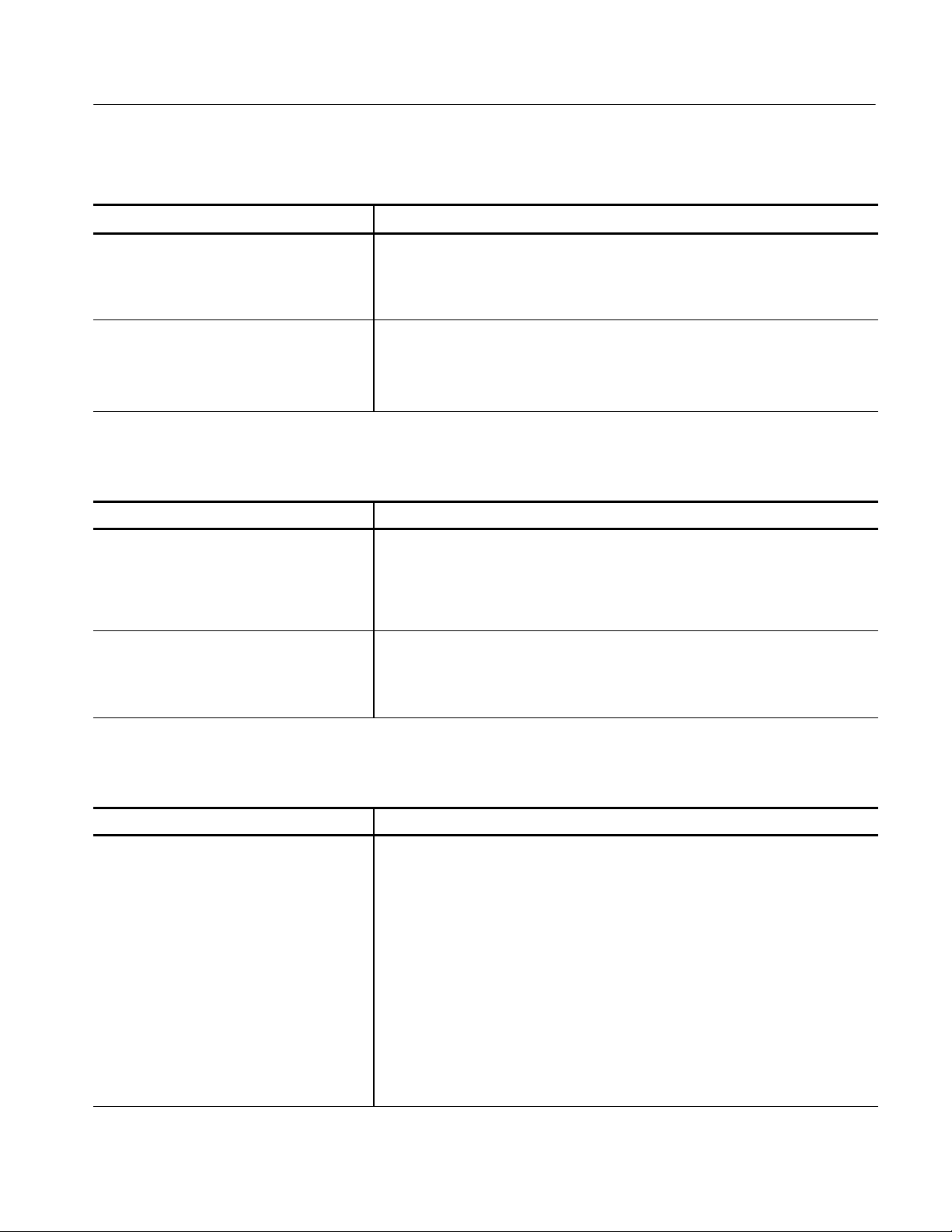
Table 1- 3: Waveform horizontal deflection ( Cont.)
Characteristic Description
External Horizontal Input Req: 2 divisions/volt, ±2%
RI: Menu is selected and enabled by REMOTE connector ground closure.
Performance Verification Procedure Step
RI: 5 V = 10 divisions
Remote Sync RI: Input Amplitude: TTL level
RI: Frequency: 25 Hz to 100 Hz positive edge-triggered sweep
RI: Enabling Signal: TTL low or ground closure
Performance Verification Procedure Step
Table 1- 4: Measurement cursors
Characteristic Description
Specifications
: 29
: 33
Waveform Accuracy(P-SPEC-CD) Req: Voltage: 0.5%
Timing: 0.5%, for line rate sweeps
RI: Typically 0.5% for field rate sweeps
Performance Verification Procedure Step
RI: Cursors are calibrated against the VAC.
: 9 & 6
V ector Accuracy(P - SPEC - CD) Req: Gain: ±1.5%
Phase: ±1°
RI: Measured with respect to the Color Bar signal
Performance Verification Procedure Step
: 10
Table 1- 5: RGB/YRGB
Characteristic Description
RGB/YRGB Req: RGB Staircase input gain: 0.8 V/division ±10%
RI: RGB Sweep Length:
1 Field ≈30% of normal
1Line≈ 30% of normal
RI: (AUD) YRGB Sweep Length:
1 Field ≈ 25% of normal
1Line≈ 25% of normal
RI: 2 kHz, 10 V square wave through REMOTE connector RGB Input.
RI: Maximum staircase operating signal: DC signal plus peakAC not to exceed
--12 V to+12 V. Line or field rate sweep.
RI: Peak-to-peak ACsignal not to exceed 12 V .
RI: Sweep Repetition Rate: Field or line rate of displayed video or external
sync signal as selected by the front-panel sweep selection
Performance Verification Procedure Step
: 30
1740A Series, 1750A Series, & 1760 Series Service Manual
1- 7
Page 26
Specifications
Table 1- 6: Calibrator
Characteristic Description
Waveform Square Wave Req: Amplitude: 1.0 V ±0.5%
Performance Verification Procedure Step
RI: Calibrated against the VAC.
Frequency: 100 kHz ±0.1%
Req:
RI: Frequency counter.
RI: Crystal controlled 10 s square wave
Performance Verification Procedure Step
: 9
: 6
Waveform Sine Wave Req: Amplitude: 1.0V
RI: Measured against the VAC.
p-p
, ±1%
V ector Circle RI: Circle that approximates the graticule compass rose
Table 1- 7: Vector mode
Characteristic Description
Input Requirements Req: 1 V peak--peak ±6dB
RI: Black burst or composite video.
RI: Instrument freeruns with no input
RI: External Reference: Black burst or composite video
V ector input range is ±12 dB.
Nominal Subcarrier Frequency (FSC) RI: NTSC 3.579545 MHz
Chrominance Processing Bandwidth (--3 dB) Req: 1MHz±200 kHz
PAL +V RI: V Axis is inverted at 1/2 video line rate
PAL 4.43361875 MHz
Performance Verification Procedure Step
RI:
Leveled sinewave generator.
: 15
Display Phase Accuracy Error Req: ≤1.25°
Performance Verification Procedure Step
RI: Color bar generator
Display Gain Accuracy Error Req: ≤2.5% with 75% amplitude color bars
Performance Verification Procedure Step
Quadrature Phasing Error Req: ≤0.5° (RI: Bursts set to targets)
Performance Verification Procedure Step
Subcarrier Regenerator Pull-in Range Req: (AUD) NTSC : ±50 Hz
PAL: ±10 Hz
Performance Verification Procedure Step
Subcarrier Regenerator Pull-in Time RI: ≤2 seconds
1- 8
1740A Series, 1750A Series, & 1760 Series Service Manual
: 23
: 23
: 22
: 24
Page 27
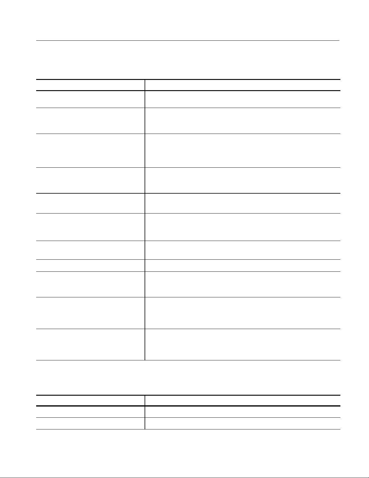
Table 1- 7: Vector mode (Cont.)
Characteristic Description
Specifications
Phase Shift with FSCChange Req: NTSC: ≤2° (FSCto FSC±50 Hz)
Phase Shift with Burst Amplitude Change of
±6dB
PAL: ≤2° (F
Req: ≤ 2°
Performance Verification Procedure Step
RI: Color bar generator.
to FSC±10 Hz)
SC
Phase Shift With Video Input Channel Change Req: ≤1°
RI: With external reference selected.
Typically ≤0.5°
Performance Verification Procedure Step
Phase Shift With Variable Gain Control +3 dB
to --6 dB
Req: ≤0.5°
Performance Verification Procedure Step
RI: Color bar generator.
Burst Jitter RI: ≤0.5° rms
RI: 140 IRE (1 V) composite video input.
Clamp Stability Req: ≤1/64 inch (0.4 mm)
RI: Center spot movement with rotation of the phase control
Performance Verification Procedure Step
Phase Control Range RI: 360° continuous rotation
Performance Verification Procedure Step
Phase Control Quantization RI: ≤0.2°
: 25
: 27
: 26
: 28
: 28
Position Control Range Req: ≥0.236 inch (6 mm) from center
Performance Verification Procedure Step
RI: Color bar generator.
Differential Phase Req: ≤1°
Performance Verification Procedure Step
RI: Measured with 140 IRE (1 Volt) linearity signal (5--step, 10-- step, or ramp)
with 40 IRE (300 mV) subcarrier.
Differential Gain Req: ≤1%
Performance Verification Procedure Step
RI: Measured with 140 IRE (1 V) linearity signal (5--step, 10--step, or ramp)
with 40 IRE (300 mV) subcarrier.
Table 1- 8: Audio mode
Characteristic Description
Input RI: DC coupled, differential input
Input Impedance RI: 20 k Ω
: 28
: 21
: 21
1740A Series, 1750A Series, & 1760 Series Service Manual
1- 9
Page 28
Specifications
Table 1- 8: Audio mode (Cont.)
Characteristic Description
Full Scale Selection RI: 0, 4, 8, & 12 dBm full scale. Menu selected
Full Scale Accuracy Req: ±0.5 dB
RI: Measured at 1 kHz
Performance Verification Procedure Step
Maximum Input Voltage RI: ±8 V peak
RI: Measured to chassis ground
Bandwidth (--3 dB) Req: -- 3 d B ≥200.0 kHz
Performance Verification Procedure Step
RI:
Leveled sinewave generator.
X & Y Input Phase Matching Req: ≤1°
RI: Measured at 20 kHz
Performance Verification Procedure Step
: 31
: 32
: 33
Table 1- 9: Time code
Characteristic Description
Input RI: Longitudinal Time Code. DC coupled, differential input
Input Impedance RI: 20 k Ω.
Input Amplitude RI: 0, 4, 8, & 12 dBm full scale. Menu
Maximum Input Voltage RI: --10 V to +10 V peak
Bandwidth (--3 dB) Req: ≥200.0 kHz
selectable for 140 IRE (1.0 V) deflection
Performance Verification Procedure Step
RI:
Leveled sinewave generator.
: 32
Table 1- 10: SCH Phase mode (1750 Series and 1760 Option SC Only)
Characteristic Description
Absolute Accuracy Req: ≤5°
RI: Applies over a temperature range of 0 -- 50° C
RI: Calibrated at 25°C. ±3 dB input amplitude.
Typically ≤5° with±6 dB input amplitude
Performance Verification Procedure Step
: 34
Relative Accuracy RI: 2°
1- 10
1740A Series, 1750A Series, & 1760 Series Service Manual
Page 29

Table 1- 10: SCH Phase mode (1750 Series and 1760 Option SC Only) (Cont.)
Characteristic Description
Acquisition Time RI: ≤1 Second
Specifications
Displayed Phase Error Caused by CRT
Geometry Variations
Input Timing RI: Stable display with Video to External Reference timing
Color Frame Range RI: ±70° (Color frame correctly identified when applied external reference
RI: ±1.25°
signal is ≤70° of 0° SCH.)
Performance Verification Procedure Step
: 34
1740A Series, 1750A Series, & 1760 Series Service Manual
1- 11
Page 30
Specifications
Table 1- 11: Component vector mode (1760 Series Only)
Characteristic Description
V ertical Bandwidth Req: --3dBat≥1.0 MHz
RI: Multiburst signal from TSG300.
Horizontal to Vertical Bandwidth Matching Req: No eye opening at 500 kHz or 2 MHz
RI: Trace-width opening with Y, P
V ertical Gain Accuracy Req: ±2.5%.
RI: With respect to graticule
Performance Verification Procedure Step
Specification will apply to the electronic graticule when it becomes available.
Horizontal Gain Accuracy Req: ±2.5%
RI: With respect to graticule
Performance Verification Procedure Step
Specification will apply to the electronic graticule when it becomes available.
Display to Graticule Registration Req: ≤0.25 box with the color bar black display dot centered in target
RI: Component signal generator.
signal applied.
R,PB
: 35
: 35
V ector Display RI: Ch A2 or B2 is displayed on the horizontal axis and Ch A3 or B3 is dis-
played on the vertical axis.
Table 1- 12: Lightning mode (1760 Series only)
Characteristic Description
V ertical Gain Accuracy Req: ±2%
RI: With respect to electronic graticule
Performance Verification Procedure Step
Horizontal Gain Accuracy Req: ±2%
RI: With respect to electronic graticule
Performance Verification Procedure Step
Electronic Graticule Display RI: Ch A1 or B1 is displayed vertically.
Ch A2 or B2 is displayed horizontally on top half of display.
Ch A3 or B3 is displayed horizontally on bottom half of display.
: 36
: 36
1- 12
1740A Series, 1750A Series, & 1760 Series Service Manual
Page 31

Table 1- 13: Bowtie mode (1760 Series only)
Characteristic Description
Common Mode Rejection Ratio Req: ≥34 dB at 3 MHz
RI: Timing error contributed by the specification limit will be less than 0.6 ns.
Performance Verification Procedure Step
RI:
Checked with a multi burst signal. Right side display should be 400 mV.
Left side display should be 8 mV.
Specifications
: 39
Electronic Graticule Display RI: Y minus PB(CH1-- CH2) is displayed on the left half of the display.
Y minus P
(CH1-- CH3) is displayed on the right half of the display.
R
Table 1- 14: Transcoded GBR outputs
Characteristic Description
Input Format
Accuracy Req: 1 ±3%
GBR Output Impedance RI: Nominally 75 Ω . Back porch clamped to 0V
RI: GBR, SMPTE, MII, or Betacam format. Selectable from a menu
RI: Typically <1%
RI: Use lightning mode of another monitor to check GBR outputs. Color bar
dots should be inside targets.
Alternate Method:
tor.
RI: No line select strobe on GBR outputs
Performance Verification Procedure Step
Component generator used to measure transcoder accuracy must have an accuracy of
≤±1%.
Measure GBR output amplitudes with a waveform moni-
: 42
1740A Series, 1750A Series, & 1760 Series Service Manual
1- 13
Page 32

Specifications
Table 1- 15: CRT display
Characteristic Description
CRT Viewing Area RI: 80 X 100 mm
Horizontal: 12.5 divisions
V ertical: 170 IRE (1.19 V)
Scan Sensitivity: Vertical: 34.5 to 43.7 V for 80 mm.
Horizontal: 91.5 to 118.5 V for 100 mm.
Accelerating Potential RI: Nominally 13.5 kV
Trace Rotation Range Req: <+and--1° from horizontal
RI: Free-running sweep.
RI: Total adjustment range is typically ≥8°.
Performance Verification Procedure Step
Graticule RI: Internal with variable illumination
Table 1- 16: Power source
Characteristic Description
Mains Voltage Range Req: 90 --250 V
RI: Check with variable auto transformer and step-up transformer.
RI: Continuous range from 90 to 250 V AC
Performance Verification Procedure Step
: 3
: 2
Mains Frequency RI: 50 or 60 Hz.
Power Consumption RI: 110 VA (67 watts) maximum; 102 VA (60 watts) typical
Table 1- 17: Environmental characteristics
Characteristic Description
Operating Temperature Req: 0° to 50° C(+32° to 122° F)
Storage Temperature Req: -- 4 0 ° to 75° C(--40° to 158° F)
Operating Altitude Req: To 15,000 feet (4572 meters)
Storage Altitude Req: T o 50,000 feet (15,240 meters)
Vibration Req: 5 minutes at 5 -- 15 Hz with 0.060 inch displacement
Mechanical Shock Req: Non Operating: 50 g’s 1/2 sine, 11 ms duration 3 shocks per surface (18 total)
5 minutes at 15 -- 25 Hz with 0.040 inch displacement
5 minutes at 25 -- 55 Hz with 0.020 inch displacement
Military Specification: Mil-- T--28800D, Paragraph 1.2.2, Class 3
1- 14
1740A Series, 1750A Series, & 1760 Series Service Manual
Page 33

Table 1- 17: Environmental characteristics (Cont.)
Characteristic Description
Transportation Req: Qualified under NSTA Test Procedure 1A, Category II (24 inch drop)
Specifications
Humidity Req: Will operate at 95% relative humidity for up to five days. Do not operate with
visible moisture on the circuit boards.
Table 1- 18: Physical characteristics
Characteristic Description
Dimensions Req: Height: 5 1/4 inches (133.4 millimeters)
Weight Req: Net: 8 pounds (3.8 kilograms)
Width: 8 1/2 inches (215.9 millimeters)
Depth: 18 1/8 inches (460.4 millimeters)
Shipping: 15.7 pounds (7.2 kilograms) approximate
1740A Series, 1750A Series, & 1760 Series Service Manual
1- 15
Page 34

Specifications
EMC
LowVoltag
e
y
g
Table 1- 19: Certifications and compliances
Category Standards or description
EC Declaration of Conformity --
1
EMC
Meets the intent of Directive 89/336/EEC for Electromagnetic Compatibility. Compliance was demonstrated to the following specifications as list ed in the Official Journal of the European Communities:
EN 55103 Product family standard for audio, video, audio-visual and entertainment lighting
control apparatus for professional use.
2
Environment E2 -- commercial and light industrial
Part 1 Emission
EN 55022 Class B radiated and conducted emissions
EN 55103--1, Annex A Radiated magnetic field emissions
EN 55103--1, Annex B Inrush current; I peak = 2.5 amps
EN-55103--1, Annex E Conducted emissions, signal/control ports
Part 2 Immunity
IEC 61000--4--2 Electrostatic discharge immunity
IEC 61000--4--3 RF electromagnetic field immunity
IEC 61000--4--4 Electrical fast transient / burst immunity
IEC 61000--4--5 Power line surge immunity
IEC 61000--4--6 Conducted RF Immunity
IEC 61000--4--11 Voltage dips and interruptions immunity
EN 55103--2, Annex A Radiated magnetic field immunity
EN 55103--2, Annex B Balanced ports common mode immunity
Australia / New Zealand
Declaration of Conformity-EMC
Complies with EMC provision of Radiocommunications Act per the following standard(s):
AS/NZS 2064.1/2 Industrial, Scientific, and Medical Equipment: 1992
FCC Compliance Emissions comply with FCC Code of Federal Regulations 47, Part 15, Subpart B, Class A Limits.
EC Declaration of Conformity -Low Voltage
Compliance was demonstrated to the following specification as listed in the Official Journal of t he
European Communities:
Low Voltage Directive 73/23/EEC, amended by 93/68/EEC
EN 61010-1:1993/A2:1995 Safety requirements for electrical equipment for measurement control
and laboratory use.
U.S. Nationally Recognized UL3111-1 Standard for electrical measuring and test equipment.
Testing Laboratory Listing
Canadian Certification CAN/CSA C22.2 No. 1010.1 Safety requirements for electrical equipment for measurement, control,
and laboratory use.
1
This product complies when installed into any of the following Tektronix instrument enclosures:
1700F00 Standard Cabinet
1700F02 Portable Cabinet
WFM7F05 Rack Adapter
2
Use only high-quality shielded cables.
1- 16
1740A Series, 1750A Series, & 1760 Series Service Manual
Page 35

Specifications
CategoryDescription
s
Table 1- 19: Certifications and compliances (cont.)
Category Standards or description
Additional Compliance IEC61010-1 Safety requirements for electrical equipment for measurement, control, and
laboratory use.
ISA S82.02.01:1999 Safety standard for electrical and electronic test, measuring, controlling, and
related equipment.
Installation (Overvoltage)
Category Descriptions
Pollution Degree Descriptions A measure of the contaminates that could occur in the environment around and within a product.
Equipment type Test and Measurement
Safety Class Class I
Overvoltage Category CAT II
Pollution Degree Pollution Degree 2
Terminals on this product may have different installation (overvoltage) category designations.
The installation categories are:
CAT III Distribution-level mains (usually permanently connected). Equipment at this level is
typically in a fixed industrial location.
CAT II Local-level mains (wall sockets). Equipment at this level includes appliances, portable
tools, and similar products. Equipment is usually cord-connected.
CAT I Secondary (signal level) or battery operated circuits of electronic equipment.
Typically the internal environment inside a product is considered to be t he same as the external.
Products should be used only in the environment for which they are rated.
Pollution Degree 1 No pollution or only dry, nonconductive pollution occurs. Products in this
category are generally encapsulated, hermetically sealed, or located in c lean
rooms.
Pollution Degree 2 Normally only dry, nonconductive pollution occurs. Occasionally a temporary
conductivity that is caused by condensation must be expected. This location is
a typical office/home environment. Temporary condensation occurs only when
the product is out of service.
Pollution Degree 3 Conductive pollution, or dry, nonconductive pollution that becomes conductive
due to condensation. These are sheltered locations where neither temperature
nor humidity is controlled. The area is protected from direct sunshine, rain, or
direct wind.
Pollution Degree 4 Pollution that generates persistent conductivity through conductive dust, rain,
or snow. Typical outdoor locations.
1740A Series, 1750A Series, & 1760 Series Service Manual
1- 17
Page 36

Specifications
1- 18
1740A Series, 1750A Series, & 1760 Series Service Manual
Page 37

Installation
Standard Accessories
The information contained here deals with the installation and operation of the
1740A/1750A/1760--Series instrument. If the instrument is to be removed from
its installed position for servicing, this will provide the information needed to
remove it or reinstall it. Note that the repackaging information is located at the
end of the Maintenance section.
This instrument is shipped with a set of standard accessories. These are the items
necessary to place the instrument in service, such as the power cord. When the
box for the instrument is opened, it should contain:
H One User Manual.
H Power cord assembly (See Options)
H One cartridge fuse.
H Three replacement graticule light bulbs.
H Three replacement air filters
Two 3.5-inch high density disks are included with this manual. The disks run on
an IBM compatible PC with a DOS 3.3 or higher operating system and a
3.5-inch high-density disk drive.
One disk contains the current operating software for the instrument. To determine the level of software loaded in an instrument, perform the following steps:
1. Power up the 1740A/1750A/1760--Series.
2. Push the CONFIG menu button.
3. Select the REMOTE submenu.
4. Read the software version number from the lower right corner of the CRT.
The other disk contains the procedure needed to return the instrument operation
to its specified levels. This procedure works in conjunction with the Adjustment
Procedures section of this manual. Version 2.2 or higher software must be loaded
in the instrument to use the Adjustment procedures.
1740A Series, 1750A Series, & 1760 Series Service Manual
2- 1
Page 38

Installation
Mechanical Installation
8.250
6.8750.688
Cabinets
Rear
0.156 Diameter (4)
12.725
1.060
5.105
6.130
16.180
Bottom Side
Figure 2- 1: Dimensions of the 1700F00 plain cabinet
The cabinets available for this instrument provide necessary shielding and
protection against accidental electrical shock, and also protect internal circuitry
against build up of dust. A supply of filtered, cooling air is provided from the
rear panel and exits through the cabinet vent holes. Operation in air flow
restricted environments may lead to excessive heat build up.
2- 2
All qualification testing for the 1740A/1750A/1760--Series instruments was
performed in a 1700F00 cabinet. To guarantee compliance with specifications,
the instrument should be operated in a cabinet. The plain cabinet, 1700F00, is
shown in Figure 2--1.
Also available are the 1700F02 Portable carrying case and the WFM7F05
side-by-side rack mount assembly. All of these cabinets are available from
Tektronix. If you need one of these cabinets, contact your nearest Tektronix field
office or representative for assistance in ordering.
1740A Series, 1750A Series, & 1760 Series Service Manual
Page 39

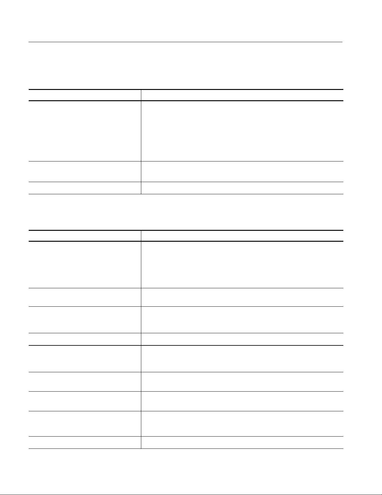
8.250
6.8750.688
Installation
5.105
5.0001.625
16.180
Bottom Side
Rear
0.141 Diameter (4)
9.435
3.310
Figure 2- 2: 1700F02 portable cabinet
The portable cabinet, 1700F02, is shown in Figure 2--2. The 1700F02 has a
handle, four feet, a flip-up stand. The mounting hole sizes and spacing are
different from those of the 1700F00.
The 1700F00, 1700F02, and WFM7F05 cabinets, which are available from
Tektronix as optional accessories, provide the proper electrical environment for
the instrument. They supply adequate shielding, minimize handling damage, and
reduce dust accumulation within the instrument.
1740A Series, 1750A Series, & 1760 Series Service Manual
2- 3
Page 40

Installation
Installing the Cabinet
CAUTION. Do not attempt to carry an instrument in the cabinet without installing
the mounting screws. Without the mounting screws, there is nothing to hold the
instrument in the cabinet if it is tipped forward.
The instrument is secured to the cabinet by two 6-32 Pozidriver screws, located
in the upper corners of the rear panel. See Figure 2-- 3.
Cabinet securing screws
Rack Adapter
Figure 2- 3: Rear view showing the secur ing screws
The optional WFM7F05 side-by-side rack adapter, shown in Figure 2--4, consists
of two attached cabinets. It can be used to mount the 1740A/1750A/1760--Series
and another half-rack width instrument in a standard 19-inch rack.
CAUTION. Be sure to read and follow the instructions that are shipped with the
rack adapter.
Use the correct sleeve for your product. The ventilation holes and EMI shielding
on the sleeves are specially designed to meet the requirements of the instruments
for which they were intended. If you use the wrong sleeve, it could damage the
instrument and cause overheating problems.
When working with instruments that are not enclosed in a chassis, you must
observe static precautions. You must also be careful not to damage circuit board
mounted components or interconnection wiring when sliding a sleeve over these
products.
2- 4
1740A Series, 1750A Series, & 1760 Series Service Manual
Page 41

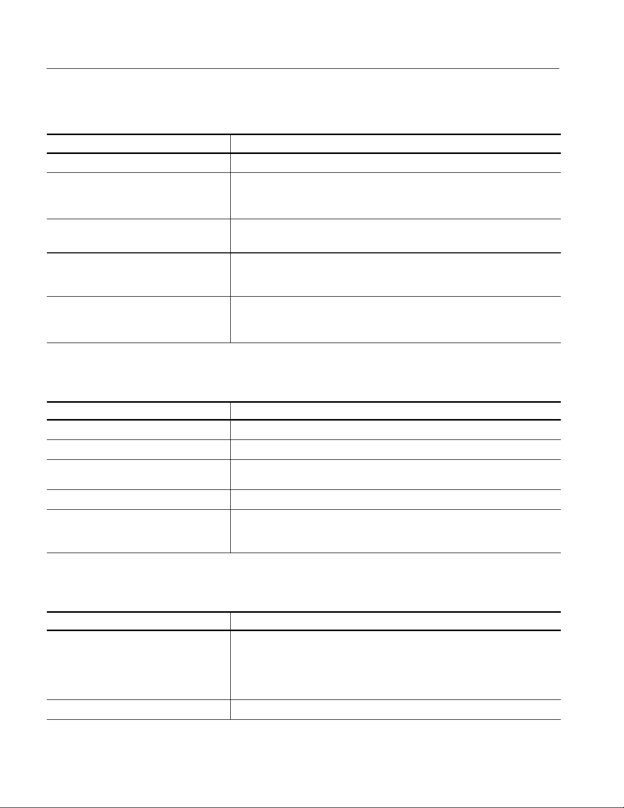
18.970
Installation
5.250
Mounting
holes
6.875
Rear view
17.270
Controls front panel
to rack alignment
Figure 2- 4: The WFM7F05 side -by-side rack adapter
The rack adapter is adjustable, so the instrument can be more closely aligned
with other equipment in the rack. See Figure 2--4.
WFM7F05
1700F06
Figure 2- 5: A W FM7F05 with a blank front panel (1700F06)
1740A Series, 1750A Series, & 1760 Series Service Manual
2- 5
Page 42

Installation
If only one side of the rack adapter is used, a 1700F06 Blank Panel can be
inserted in the unused section. See Figure 2--5. The rack adapter and panel are
available through your local Tektronix field office or representative.
When only one instrument is mounted in the side-by-side adapter, an accessory
drawer (1700F07) can be installed in the blank side of the cabinet. See
Figure 2--6.
WFM7F05
1700F07
Figure 2- 6: WFM7F05 rack mount cabinet with a 1700F07 utility drawer
2- 6
1740A Series, 1750A Series, & 1760 Series Service Manual
Page 43

Installation
Custom Installation
For applications such as consoles, the instrument can be mounted with front
molding flush or protruding from the console. In both cases, allow approximately 3 inches of rear clearance for BNC and power-cord connections.
To mount the instrument safely, attach it to a shelf strong enough to hold its
weight. Install the mounting screws through the four 0.156-inch diameter holes
in the bottom of the 1700F00 cabinet. See Figure 2--7.
For flush front panel: Cut hole the
same size as the monitor front molding
to allow the monitor front panel to align
with the custom panel surface.
Requires four 0.156” holes below
the 1700F00 cabinet to secure
the instrument to the shelf.
For protruding front molding:
Cut hole in panel the same size as the
opening in the monitor cabinet to allow
the front panel molding to cover the hole.
Figure 2- 7: Custom installation of an instrument
1740A Series, 1750A Series, & 1760 Series Service Manual
2- 7
Page 44

Installation
Electrical Installation
Power Source
Mains Frequency and
Voltage Range
Power Cord Options
Operational Changes
These monitors are designed to operate from a single-phase power source having
one of its current-carrying conductors at or near earth ground (the neutral
conductor). Only the line conductor is fused for over-current protection Systems
that have both current-carrying conductors live with respect to ground (such as
phase-to-phase on multiphase systems) are not recommended as power sources.
A protective ground connection by way of the grounding conductor in the power
cord is essential for safe operation.
WARNING. When power is supplied, line voltage will be present in the instrument, even if the
The 1740A/1750A/1760--Series monitors operate at 50 and 60 Hz, over the range
of 90--250 Volts, without operator adjustment.
These instruments ship with a standard North America power cord, unless a
power cord option was ordered. Table 7--1 in the Options section shows the
available options.
No operational modifications are made to this monitor through internal jumper
settings.
POWER switch is set to STANDBY.
2- 8
1740A Series, 1750A Series, & 1760 Series Service Manual
Page 45

Rear Panel Connectors
Installation
Signals into and out of the instrument are connected via the rear panel. Video
signals are input/output through the BNC connectors, except for the RGB
staircase signal which is input through the REMOTE connector. General
information about the rear panel connectors is provided in the following
paragraphs. Figure 2--8 shows the rear panel configuration for a 1760--Series
instrument. The only difference between the 1760--Series rear panel and the other
instrument rear panels is the presence of the GBR outputs.
PIX
OUT
G
B
EXT
REF
R
75 OHM LOOP-THROUGH COMP E NSATED
A3 A2 A1 A
75 Ω Loop-Through
Video Inputs
External Reference
(EXT REF)
B3 B2 B1 B
51 13 1
96
RS232
25 14
REMOTE
Figure 2- 8: Rear panel connect ors
There are a total of eight 75 Ω compensated loop-through video input BNC
connectors. These inputs are not internally terminated; inputs require 75 Ω
external termination to provide accurate measurement capabilities. Inputs A and
B are dedicated composite inputs regardless of instrument type. Inputs
A1--A2--A3 and B1--B2--B3 can also be used as composite inputs, but if
component signals are to be displayed, they become the component inputs.
Maximum operating input voltage for all inputs is --1.8 V to +2.2 V DC plus
peak AC. Absolute maximum input voltage is --8.5 V to +8.5 V DC plus
peak AC.
The external reference input provides both external synchronizing signals and
external subcarrier input to these instruments. Input is either black burst or
composite video. It is a 75 Ω compensated loop-through input, requiring external
termination.
1740A Series, 1750A Series, & 1760 Series Service Manual
2- 9
Page 46

Installation
Picture Monitor Out
(PIX OUT)
GBR Output
Remote Connector
The PIX OUT is a 75 Ω, nonfiltered output designed to drive a picture monitor.
A bright-up strobe is added when the instrument is operated in the line select
mode. Strobe will either be the line in the selected field, the line in all fields or
of 15 lines duration in the selected field or all fields. In the 15-line mode, the
bright up starts with the selected line.
1760--Series Only. These three 75 Ω outputs are from the color difference-to-
GBR transcoder. When the input is RGB, the transcoder is bypassed. The G
(green) output contains sync.
The rear-panel REMOTE connector is a 25-pin, D-type connector. It provides the
input for stereo L and R audio. TTL signal or ground closure to designated pins
are the enables. Eight front-panel setups can also be stored and recalled through
the Remote connector. Table 2--1 shows pin assignments and Figure 2--9 shows
the connector.
13
1
1425
REMOTE
!
Figure 2- 9: Rear panel REMOTE connector.
2- 10
1740A Series, 1750A Series, & 1760 Series Service Manual
Page 47

Table 2- 1: Remote connector
Pin number Function Signal requirement Miscellaneous information
Installation
1 RGB/YRGB Staircase Input
External Horiz. Input
2 Ground
3 Staircase/Ext. Horiz. Enable Ground (TTL low) Grounding enables the function. (Staircase or external horizontal
4 External Blanking Input Negative-going signal Enabled by menu selection.
5 Remote Sync Input TTLlevel square wave
6 Remote Sync Enable Ground (TTL low) Grounding enables the function.
7 Ground
8 +Y Audio Input Max. Input ±8 V peak. Left in phase. Measured to Chassis Ground.
9 --Y Audio Input Max. Input ±8 V peak. Left out of phase. Measured to Chassi s Ground.
10 +X Audio Input Max. Input ±8 V peak. Right in phase. Measured to Chassis Ground.
11 --X Audio Input Max. Input ±8 V peak. Right out of phase. Measured to Chassis Ground.
12 + Time Code Input --10 -- +10 V peak. Longitudinal Time Code, differential.
13 -- Time Code Input --10 -- +10 V peak. Longitudinal Time Code, differential.
14 Ground
+10 V for RGB/YRGB
0 -- +5 V Sawtooth
triggers 2-field sweep.
≈9 divisions of sweep. (Staircase/external horizontal and
RGB/YRGB selected through the menu.)
10 divisions of horizontal deflection.
selected through the menu.)
30/90 Hz for NTSC
25/100 Hz for PAL
15 & 16 Not used
17 Preset 1 Ground (TTL low) Ground pin 17 to recall front-panel setup from preset 1. Ground
pins 17 and 25 to store current front-panel setup at preset 1.
18 Preset 2 Ground (TTL low) Ground pin 18 to recall front-panel setup from preset 2. Ground
pins 18 and 25 to store current front-panel setup at preset 2.
19 Preset 3 Ground (TTL low) Ground pin 19 to recall setup from preset 3. Ground pins 19 and
25 to store current setup at preset 3.
20 Preset 4 Ground (TTL low) Ground pin 20 to recall setup from preset 4. Ground pins 20 and
25 to store current setup at preset 4.
21 Preset 5 Ground (TTL low) Ground pin 21 to recall setup from preset 5. Ground pins 21 and
25 to store current setup at preset 5.
22 Preset 6 Ground (TTL low) Ground pin 22 to recall setup from preset 6. Ground pins 22 and
25 to select preset 6 as storage location for current setup.
23 Preset 7 Ground (TTL low) Ground pin 23 to recall setup from preset 7. Ground pins 23 and
25 to select preset 7 as storage location for current setup.
1740A Series, 1750A Series, & 1760 Series Service Manual
2- 11
Page 48

Installation
Table 2- 1: Remote connector (Cont.)
Pin number Miscellaneous informationSignal requirementFunction
24 Preset 8 Ground (TTL low) Ground pin 24 to recall setup from preset 8. Ground pins 24 and
25 to select preset 8 as storage location for current setup.
25 Store Ground (TTL low) Ground this pin along with one of the Preset pins to store the
current front-panel setup at the selected Preset location.
Remote Connector Converter
If the 1740A/1750A/1760--Series replaces a 1740/1750--Series instrument, rewire
the remote cable or provide an adapter as shown in Figure 2--10
If the 1740A/1750A/1760--Series replaces an Option 16 instrument, construct the
adapter in the same manner, omitting the pin 3-to-pin-25 connection.
1740A/1750A/1760--Series
rear-panel REMOTE connector
1
14
3
5
6
7
25
13
*(Do not connect when replacing Option 16 instruments.)
RGB INPUT
RGB
ENABLE*
REMOTE SYNC IN
GROUND
REMOTE SYNC ENABLE
Figure 2- 10: Replacement adapter for 1740/1750
Remote plug
1
14
19
8
9
10
25
13
2- 12
1740A Series, 1750A Series, & 1760 Series Service Manual
Page 49

RS232 Connector
Installation
This 9-pin subminiature D-type connector provides a serial interface for remote
control. It has a driver built in for RS232 serial binary data interchange. The
operational mode is full duplex. Data rate = 9600 baud; data type is asynchronous. Figure 2-- 11 shows pin assignments and connector orientation.
54321
9876
RS232
1 DCD
2 Receive Data (RxD)
3 Transmit Data (TxD)
4 Data Terminal Ready (DTR)
5 Signal Ground (GND)
Figure 2- 11: Rear panel RS232 connector
6 Data Set Ready (DSR)
7 Request to Send (RTS)
8 Clear to Send (CTS)
9 No connection
1740A Series, 1750A Series, & 1760 Series Service Manual
2- 13
Page 50

Installation
Installing Software
These versatile monitors can be upgraded to perform additional measurements or
to revise operations. Software code is contained in Flash EPROM that can be
written over when upgrades become available.
If you replace the Flash EPROM, you must reinstall the software from the
software disk accompanying this manual.
To find the current version of software, go to the CONFIG menu and then to the
REMOTE submenu. The version number, preceded by the letter V, is displayed
in the lower right corner of the screen.
Software Disk
Required Equipment
The software disk is a 3.5” (1.44MB) high-density disk. It contains all programs
necessary to upgrade or reload the operating software in the Tektronix
1740A/1750A/1760--Series instruments. If a disk drive other than 3.5” is to be
used, copy the contents of the disk to the desired size disk or to a hard disk
directory. The disk contents are:
NVSAVE.EXE. Saves calibration constants and user presets.
CONVERT.EXE.Updates format of calibration and preset data.
UPGRADE.EXE. Performs software upgrade.
NVRESTOR.EXE. Restores calibration constants and user presets.
NEW_CAL.EXE. Used to calibrate new features.
SOFTWARE.BIN. Data file used by UPGRADE.EXE.
IBM Compatible PC with the following
H DOS 3.3 or Higher.
H 640 K Bytes Random-Access Memory (RAM).
H High Density Floppy Drive (3.5”/1.44 MB).
2- 14
H Available RS232 Port (COM 1, 2, 3, or 4).
H RS232 Cable to connect PC to the 1740A/1750A/1760--Series R S232
connector.
1740A Series, 1750A Series, & 1760 Series Service Manual
Page 51

Installation
Instrument Reset
Certain conditions, such as removing the power source while a program is
running, may cause the 1740A/1750A/1760--Series instrument front-panel
controls to become locked.
Reset as
Turn off instrument power, then depress CLEAR MENU and WAVEFORM,
holding in both buttons until you have turned instrument power on again and the
instrument has returned to its normal operating state.
CAUTION. Loading new software will result in the loss of instrument calibration
constants and user presets. Therefore, the program NVSAVE must be run before
executing UPGRADE.
If a disk is used to upgrade more than one instrument, finish one upgrade,
including the NVRESTOR program, before running NVSAVE on the next
instrument. NVSAVE will overwrite the temporary files on the disk every time it
is run; any previous files will be lost.
The programs are designed to read or create their respective files in the current
DOS directory. If you choose to copy these files to a hard drive, be sure to run
them from the directory in which they are contained.
The instrument cannot be used during execution of any of the programs on this
disk. If the operation of any of these programs is interrupted, that program must
be rerun from the beginning to ensure a proper upgrade.
follows:
1740A Series, 1750A Series, & 1760 Series Service Manual
2- 15
Page 52

Installation
Loading Software
PC Hookup Hook up the 1740A/1750A/1760--Series rear-panel RS232 connector
to the COM 1, 2, 3, or 4 connector on the PC, as shown in Figure 2--12 or Figure
2--13. If pins two and three (RXD and TXD) are swapped, as in some MODEM
connections, the upgrade will not operate.
9-Pin female
connector to PC
1
6
9
5
Standard hookup
9-Pin female
connector to PC
1
6
9
5
Alternate hookup
Signal ground
Signal ground
9-Pin male connector to
1740A/1750A/1760-Series
1
5
9-Pin male connector to
1740A/1750A/1760-Series
1
5
1 DCD
2 Receive Data (RxD)
6
3 Transmit Data (TxD)
4 Data Terminal Ready (DTR)
5 Signal Ground (GND)
6 Data Set Ready (DSR)
7 Request to Send (RTS)
9
8 Clear to Send (CTS)
9 No connection
6
9
2- 16
Figure 2- 12: Standard and alternate hookups for the 9-pin connector
1740A Series, 1750A Series, & 1760 Series Service Manual
Page 53

Installation
25-Pin female
connector to PC
14
20
25
Standard hookup
25-Pin female
connector to PC
14
20
1
2
3
4
5
6
7
8
13
1
2
3
4
5
6
7
8
Signal ground
Signal ground
9-Pin male connector to
1740A/1750A/1760-Series
1
2
3
5
9-Pin male connector to
1740A/1750A/1760-Series
1
5
6
9
6
2
3
4
7
8
9
25
13
Alternate hookup
Figure 2- 13: Standard and alternate hookups for 25-Pin PC Connector
1740A Series, 1750A Series, & 1760 Series Service Manual
2- 17
Page 54

Installation
Procedure for
Loading Software
1. Run
NVSAVE
(Execution time <1 minute)
a. Power on the 1740A/1750A/1760-Series instrument.
NOTE.PCDiskDriveorHardDisk
On PCs, the drive letter for the disk drive may be A, B, etc. Enter the appropriate letter for your disk drive in the following steps. If the disk contents were
copied to a hard disk directory, run the programs from that directory.
b. Insert disk into PC 3.5 inch disk drive.
CAUTION. In order to execute “NV SAVE”, the disk is not
not
place it in write protect mode.
c. At the
DOS prompt, type “B:” and ENTER.
write protected . Do
d. Type “NVSAVE” and ENTER. When asked for the COM port, respond with
the number of the port you are using. (If you enter an incorrect port
number, you will be prompted to try again.)
The program stores the following temporary files on the disk:
CALS.TMP (calibration constants)
PRESET.CUR (instrument’s current front-panel setup)
PRESET.001--009 (user-defined presets)
PRESET.FCT (factory-defined preset)
e. Wait for the message that the program execution is completed.
2. Run
CONVERT
(Execution time <1 minute)
a. Type “
CONVERT” and ENTER.
3. Prepare Waveform Monitor for Upgrade
a. Turn instrument power to STANDBY.
WARNING. When power is supplied, line voltage will be present in the instrument, even if the POWER switch is set to STANDBY.
b. Move the plug jumper on J4 (Main board) to pins 1 and 2 (the pins
closest to U14).
2- 18
1740A Series, 1750A Series, & 1760 Series Service Manual
Page 55

Installation
c. Set switch 4 of SW1 to the open position. (SW1 is the red switch on the
Main board, near the front of the instrument.)
d. Turn on the instrument and allow it to boot (wait a few moments until
the 1740A/1750A/1760-Series CRT and front-panel LEDs are illuminated as for normal operation).
4. Run UPGRADE
(Execution time ¶12 minutes)
NOTE. If a power loss to either the PC or the 1740A/1750A/1760-Series occurs
during software loading, the instrument may lock up and not restart normally. If
this occurs, refer to the special recovery procedure on page 2--20.
a. Be sure that
b. At the
NVSAVE was executed (step 1).
DOS prompt, type “B:” and ENTER.
c. Type “UPGRADE” and ENTER. When asked for the COM port, respond
with the number of the connector you are using.
d. W ait for the message that the program execution is completed.
e. Turn off the 1740A/1750A/1760-Series instrument power.
f. Return the plug jumper to pins 2 and 3, and return #4 of SW1 to the
closed state.
g. Turn on instrument power to enable the new software.
5. Run NVRESTOR
(Execution time <1 minute)
a. At the
DOS prompt, type “B:” and ENTER.
b. Type “NVRESTOR” and ENTER. When asked for the COM port, respond
with the number of the port you are using.
c. Wait for the message that the program execution is completed.
d. Verify that step 4f has been performed.
e. This completes the Software Upgrade Procedure.
1740A Series, 1750A Series, & 1760 Series Service Manual
2- 19
Page 56

Installation
Calibrating New Features
The new instrument features must be calibrated using the following procedure. A
color bar signal is required.
1. Run NEW_CAL
NOTE. Each time an adjustment is indicated in the following steps, type the given
letter on the PC keyboard, and then press the up/down or left/right keyboard
arrows as many times as required to achieve the described adjustment. The
arrows function as follows
→
large increase
←
large decrease
a. After installing the new version software, with the RS232 cable still
attached and the instrument operating, type “
:
↑
small increase
↓
small decrease
NEW_CAL” and ENTER.
2. Calibrate the new features.
a. Perform steps A through I for all instruments.
b. Perform steps J and K for 1760-Series.
c. Type X to exit the program.
Special Recovery for Power Loss During the Execution of UPGRADE
If there is a power failure to either the instrument or the PC while the software is
loading, the following recovery procedure is necessary:
1. Turn the 1740A/1750A/1760-Series front-panel POWER switch to STANDBY.
2. Start the PC upgrade procedure program and proceed through the menus
until the SELECT COM PORT menu is on screen.
3. Type in the number of the COM P ORT, but do not
4. Turn the 1740A/1750A/1760-Series front-panel POWER switch to ON.
5. Within 6 seconds, press RETURN on the PC.
press RETURN.
2- 20
1740A Series, 1750A Series, & 1760 Series Service Manual
Page 57

Operating Information
This section contains a brief introduction, minimal operating instructions,
general menu information, an overview of the instrument functions, and brief
instructions for displaying the desired signal. Consult the user manual if you
need a more complete explanation.
Getting Started
You should be aware of the following special characteristics of the
1740A/1750A/1760--Series:
H Composite (NTSC or PAL) signals can be connected to any or all of the
eight input channels. Three-channel component (for example, GBR or Y, P
P
) signals should be connected to inputs A1--A2--A3 and B1--B2--B3. Select
R
the CONFIG/INPUT display to configure the “A123” and “B123” inputs for
the type of signal you are monitoring.
H Each type of Waveform display (one line, two line, one field, and two field)
has one level of horizontal magnification that can be turned on and off with
the MAG button. The level of magnification depends on the display type;
you can sequentially display the four magnified views by repeatedly pressing
the Line/Field SWEEP button (once SWEEP MAG has been selected).
,
B
H The 1760--Series BOWTIE Display subtracts channels 2 and 3 from
channel 1 and automatically displays the results in a parade format; when
“A123” is selected, the A1 minus A2 waveform is shown to the left of the
A1 minus A3 waveform. This lets you use the Tektronix-developed Bowtie
test signal to check and adjust inter-channel timing on component systems.
H The rear-panel REMOTE connector accepts audio signals. See Appendix B
of the user manual for the pin assignments.
H The five buttons arranged vertically to the right of the display are called
Bezel Buttons. Use these buttons to toggle or select on-screen menu options.
H The middle three knobs under the display are called Bezel controls. Turn
these knobs to adjust the parameters (or scroll through the lists) that appear
above them on the display screen.
1740A Series, 1750A Series, & 1760 Series Service Manual
2- 21
Page 58

Operating Information
Operating Instructions
1. Connect the instrument to the desired s ignal path(s). Remember to connect
component signals to A1--2--3 or B1--2--3. Be sure that all paths are
terminated; add a termination to the loop-through connector, as necessary .
2. Plug the instrument in and switch it on. The On/Standby (POWER) switch is
on the bottom right corner of the front panel.
3. Select the CONFIG menu with its front-panel button and adjust the
parameters as required for your particular installation.
VERT POS
HORIZ P OS
CLEAR
MENU
MULTIPLE
INPUT
CH A
CH B
CH A 1
CH B1
CH A 2
CH B2
CH A 3
CH B3
A 123
B 123
PARADE
OVERLAY
1760
DISPLAY
VECTOR
SCH
LIGHTNING
BOWTIE
LINE
FIELD
MAG
DC REST
RESTORE
REF
EXT
WAVEFORM/
VECTOR MON ITOR
WAVEFORM
AUDIO
PICTURE
TIME CODE
MENUSWEEP
FILTER
CURSOR
LIN SEL
PRESET
CONFIG
GAIN
CRT
POWER
ON/
STANDBY
Figure 2- 14: 1760 front panel
2- 22
4. Use the DISPLA Y and INPUT buttons to view some aspect of the desired
signal.
5. Select the CRT menu to adjust the waveform, readout, and scale brightness,
and the waveform focus. Press the CLEAR MENU button to remove the
menu from the display.
6. Use the front panel controls (Figure 2--14) to observe and measure the
desired signals. For more details, see the following pages or the user manual.
1740A Series, 1750A Series, & 1760 Series Service Manual
Page 59

General Menu Information
The next few paragraphs describe the general techniques for using the menus.
To get started, press a MENU button (on the far right of the front panel) to call
up one of the menu readouts.
Operating Information
Multi-Use Bezel Controls
and Buttons
Menu selections appear along the right side of the screen. Descriptive labels,
when present, appear in ITALIC text
. Selections appear in Roman (standard) text,
with the current selection outlined. Use the five bezel buttons along the right side
of the CRT to change the selections. Figure 2--15 shows the bezel controls and
buttons.
DISPLAY
READOUT
TRACE
Bezel
buttons
TEST
ON OFF
FOCUS SCALE INTENSITY
VERTPOS
Left Center Right
HORIZPOS
CLEAR
MENU
Bezel controls
Figure 2- 15: The CRT m enu, with the bezel controls and buttons
The center three controls under the CRT are referred to as Left, Center, and Right
bezel controls. Control functions vary with menu choice; a readout just above
each active knob shows its present function. The knobs are used as variable
analog controls to set values such as phase, amplitude, and intensity. The left
control is also used to scroll and select categories within the CONFIG menu.
Moving Between Menus
Selecting a second menu removes the present menu display, but the functions
typically remain active (with the menu LED remaining lighted to show this
state). To reinstate a menu display, press that menu button again. CRT, PRESET,
and CONFIG menus are exited completely when another menu button is pressed.
1740A Series, 1750A Series, & 1760 Series Service Manual
2- 23
Page 60

Operating Information
Clear Menu
Exiting a Menu Function
Press CLEAR MENU to clear part of the menu display, but leave essential
readout elements such as control assignments and measurement readouts. (The
menu LED remains lighted to show this state.) Press the menu button to bring
back the full display. CRT, PRESET, and CONFIG menus are exited completely
when CLEAR MENU is pressed.
To exit a menu function while its display is present, press that menu button. (The
menu button functions as an on-off toggle switch). If the menu display is not
present, but the menu function is still in effect (LED is lighted), press the menu
button to bring back the full display, then press it again to exit the menu.
2- 24
1740A Series, 1750A Series, & 1760 Series Service Manual
Page 61

Functional Overview
Operating Information
The Functional Overview tells how to use your instrument to monitor a signal.
To select a particular signal, see Displaying a Signal on page 2--27.
Display Modes
Vector
The displays that can be chosen for each type of signal are listed in Table 2--2
and explained in the following paragraphs.
Table 2- 2: The available display modes
Mode Composite Component
Vector Yes 1760--Series only
SCH 1750A--Series & 1760--Series, Option SC only
Waveform Yes Yes
Audio Yes (using REMOTE input) Yes, using REMOTE
input
Lightning & Diamond 1760--Series only
Bowtie 1760--Series only
Picture Yes Yes
Time Code Ye s Yes
Multiple Displays Yes Yes
The vector mode presents an XY plot of demodulated chrominance phase and
amplitude. The angle represents chrominance phase and the distance from the
center represents chrominance amplitude. A bezel control adjusts vector phase
.
With a component input (A123 or B123), the vector display is channel 3
SCH
(typically R--Y or P
SCH (the 1750A--Series and 1760--Series with option SC only) provides a vector
) versus channel 2 (typically B--Y or PB).
R
display of the subcarrier-to-horizontal-sync phase relationship. The burst vector
and the phase of the 50% point of the leading edge of sync are displayed.
Subcarrier-to-horizontal phase and color framing are displayed graphically in the
polar SCH display. Sync jitter over the field shows as a moving sync vector dot.
You can verify correct color framing by the position of the single sync vector dot
relative to the color subcarrier vector when the monitor is externally referenced.
The SCH phase of the reference signal is separately sensed to allow reliable color
framing comparison. Using this method of determining relative color framing
1740A Series, 1750A Series, & 1760 Series Service Manual
2- 25
Page 62

Operating Information
eliminates the requirement for a precise horizontal timing match between the
reference and measured signals.
Waveform
Audio
Lightning and Diamond
(1760- Series only)
The waveform monitor portion of the instrument provides a voltage-versus-time
display of the video signal. The selected input can be displayed in one or two
line, or one or two field sweeps. In LINE SELECT mode, identified lines of any
field can be selected and displayed. Multiple inputs can be displayed, or multiple
filters can be used on one input for signal analysis. TIME and VOLTAGE
cursors can be activated and positioned for reference or measurement.
Audio amplitude and phase is monitored using a calibrated X/Y Lissajous
display. You can verify that the program audio will be properly reproduced on
both monaural and stereo receivers. Correct phasing between two audio channels
is verified by the direction of the display.
The front-panel LIGHTNING button is used for both the Lightning and the
Diamond displays. Use the DISPLAY buttonontheCONFIG/FORMATmenuto
toggle between the Lightning and Diamond displays. Press the front panel
CLEAR MENU button to remove the menu from the screen.
Selecting Lightning mode forces the instrument to A123 input display; it can be
changed to B123 with the front-panel button.
NOTE. A123 (or B123) must be configured as a component input (through the
COMPONENT/INPUT menu) for proper LIGHTNING or DIAMOND display.
2- 26
Bowtie
Picture
In BOWTIE mode (1760--Series only), the display is forced to a two line or field
sweep and the A123 input is selected. The left half of the display shows CH-1
minus CH-2 and the right half shows CH-1 minus CH-3. If the timing between
channels is matched, the centers of the bowties will be centered and not skewed.
If CH-2 is delayed with respect to CH-1, the skew moves to the right. If CH-2 is
advanced with respect to CH-1, the skew moves to the left.
NOTE. A123 (or B123) must be configured as a component input (through the
COMPONENT/INPUT menu) for proper BOWTIE display.
The PICTURE mode allows the operator to verify the signal source. In PICTURE mode with LINE SELECT on, a bright-up marker identifies the selected
line in the picture.
1740A Series, 1750A Series, & 1760 Series Service Manual
Page 63

Operating Information
Time Code
Multiple
Displaying a Signal
Inputs
Longitudinal time code is monitored in a frame-rate display to allow observation
of amplitude, synchronization, and phase with respect to reference vertical sync.
Synchronization is confirmed by the stationary display and time code phase is
determined by horizontal position of the time code sync word on the CRT.
When MULTIPLE is pushed, WAVEFORM, VECTOR, and SCH (Option SC
only) can be selected at the same time.
When exiting MULTIPLE, the instrument will return to the previous (non-MULTIPLE) display settings. When entering MULTIPLE again, the previous
MULTIPLE display settings will be restored.
The following paragraphs describe how to use the front-panel buttons to display
exactly the signal or signals you want.
There are eight rear-panel loop-through inputs, which may eliminate the need for
an external routing switcher. The inputs can be displayed singly or in several
different combinations.
A123/B123
Without PARADE or OVERLAY selected, only one input selection can be made
at a time. Each input channel button (including A123/B123 or SELA/SELB)
toggles between A and B, and is cancelled when another input button is pressed.
With PARADE or OVERLAY selected, the input channels can be displayed in
combination. Pressing an input channel button sequences through the labeled
channels, both, then off. Pressing another input button does not cancel the
current selection, but adds to it. To return to “single input” operation, press the
PARADE/OVERLAY button until it is off (LED is no longer lighted).
Inputs A1--A2--A3 and B1--B2--B3 may be used either as inputs for three-wire
component signals, or inputs for three separate composite signals. (The
CONFIG/INPUTS menu settings must match the actual signal type.)
Selecting A123 provides a side-by-side display of the CH-A1, CH-A2, and
CH-A3 inputs (B123 displays the CH-B1, CH-B2, and CH-B3 inputs).
When PARADE or OVERLAY is selected, A123 and B123 can be displayed
together and in combination with other inputs. If both A123 and B123 are
selected, the display will consist of a side-by-side display of channels A1, A2,
and A3, overlaid with a side-by-side display of channels B1, B2, and B3.
1740A Series, 1750A Series, & 1760 Series Service Manual
2- 27
Page 64

Operating Information
Parade
Overlay
Sweep
Selecting PARADE independent of A123/B123 displays the input channels last
selected for PARADE, allowing a custom configuration of inputs. In PARADE
mode, the LINE/FIELD button offers only two choices: one line and one field.
PARADE allows up to four channels to be displayed side-by-side. Additional
channels will be overlaid.
OVERLAY superimposes the selected input signals. In OVERLAY mode, the
LINE/FIELD button remains a four-way toggle, providing one line, two line, one
field, and two field displays.
Sweep buttons select the waveform sweep rate. LINE/FIELD toggles through
four sweep rate selections: one line, two line, one field, and two field. In
PARADE mode, the LINE/FIELD button becomes a two-way switch, toggling
between line and field.
The MAG button is used with LINE/FIELD to provide horizontal magnification
of each rate as follows:
H One line magnified = 200 ns/division
H Two line magnified = 1 µs/division
H One field or two field magnified = approximately
X20 magnification.
2- 28
1740A Series, 1750A Series, & 1760 Series Service Manual
Page 65

Block Diagram Description
The 1740A Series of monitors provides the typical composite displays used to
monitor video quality. The 1750A Series adds SCH phase measurements. The
1760 Series provides both composite and component analog capabilities.
Option SC added to the 1760 Series provides SCH phase measurements.
The three block diagrams discussed here are located in the Diagrams and Circuit
Board Illustrations, at the rear of this volume. Circuits shown on a diagonal
patterned background are not present in the 1740A Series instruments; these are
the unique circuits for the 1750A Series and the 1760 Series.
Signal flow, microprocessor-generated levels, and feedback lines are shown as
solid lines. Control lines are shown as dashed lines. Signal flow is from left to
right on these diagrams.
Block Diagram 1: Input and Waveform Monitor
Input Amplifier, Clamp,
and Input Selection
Horizontal Reference
Multiplexer and Reference
Switch
There are eight identical clamped input amplifiers. Their gain is approximately
unity. They are of the bridging loop-through type and are compensated for 75Ω
characteristic input impedance. All inputs are active and a multiplexer is used to
select signals for display. All three instrument series can accept both composite
and component inputs. Input coupling can be either ac or dc as selected from the
Configure menu. Clamp timing and clamping point are selected in the same
manner. Coupling and clamping selections are for all inputs; they cannot be
individually changed.
The Input Multiplexer provides the means to select the input signal for display.
Selection of signals is controlled by the Line Rate Controller in response to front
panel switch selections. The choices are: a single input, a parade of three inputs,
or an overlaid display of the same three inputs. Overlay display is at the selected
line or field rate. Parade display is three consecutive lines or fields beginning
with the A1 or B1 input signal followed by A2 or B2 and A3 or B3.
In addition to driving the Input Multiplexer the video signal also drives the
Horizontal Reference Multiplexer to select the internal sync and subcarrier
references for the Line Rate Controller, chroma for the vectorscope, and SCH
Phase.
The Internal/External Reference switch selects either the internal video or the
external reference input as the instrument sync and subcarrier reference. Both the
Multiplexer and the Reference Switch are controlled by outputs from the Line
Rate Controller.
1740A Series, 1750A Series, & 1760 Series Service Manual
3- 1
Page 66

Block Diagram Description
Pix Out, Filters, and
Calibrator
Auxiliary Switching
The Input Multiplexer drives both the Picture Monitor Out (Pix Out) and the
chrominance and luminance filters. The filters can be bypassed to provide an
unfiltered (Flat) display. The Pix Out signal, with or without line select bright up
(strobe), is the buffered, unprocessed input signal from the Input Multiplexer.
The Pix Out has a characteristic output impedance of 75Ω to match the input
impedance of picture monitors.
In addition to removing chrominance for the displayed video, the Luminance
Filter drives the Diff Step Filter, and an input to the Horizontal Amplifier where
the monochrome Pix Mon intensity signal is derived.
There are chrominance filters for both of the color standards that filter both the
input video signal and the output of the F
generates the test circle for the vectorscope. Output of the appropriate color
standard Chroma Filter is selected by a microprocessor-generated switching
signal. The chrominance signal is routed through the Vertical Amplifier, is
buffered, and drives the vectorscope Chroma Amplifier.
The calibrator provides a 1 volt, 100 kHz output. Its amplitude is controlled by
the microprocessor and its timing is set by the Line Rate Controller.
The Auxiliary Switching, controlled by the Line Rate Controller extends the
number of signals that can be input to the Filter Selection Multiplexer. In
addition to being an input to the Auxiliary Switching the differential time code
input is recovered, buffered, and output to the microprocessor which generates
time code display synchronizing signals.
Oscillator. The FSCOscillator
SC
Filter Selection Multiplexer
Vertical Amplifier
3- 2
The Filter Selection Multiplexer selects one of seven inputs, including the
Auxiliary Switching, to be displayed. The vectorscope R--Y and the component
vertical signal outputs are input through this multiplexer.
The Vertical Amplifier is a variable gain amplifier that has controlling inputs
driven by either microprocessor or synchronous Line Rate Controller outputs.
Stage gain is controlled by the microprocessor-generated DAC converted control
voltages. Magnification is switched by a signal from the Line Rate Controller.
An offset voltage from the DACs vertically positions the display.
When the CRT readout is being processed, the Line Rate Controller changes the
gain of the amplifier. The differential output of the Vertical Amplifier drives the
vertical output amplifier to normalize signal amplitude and drive the CRT
deflection plates.
An additional internal amplifier stage provides a chrominance differential output
to drive the vector chroma amplifier. Gain of the chrominance signal is controlled by the microprocessor.
1740A Series, 1750A Series, & 1760 Series Service Manual
Page 67

Block Diagram Description
Sweep Generators and
Horizontal Signal
Multiplexer
Horizontal Amplifier
Line and Field Rate signal generators are started and stopped by the retrace
signals from the Line Rate Controller. Sweep ramp run up times ≈17 ms for the
field sweep and 64 s for the line sweep are controlled by the microprocessor.
The Horizontal Signal Multiplexer is controlled by the Line Rate Controller to
select a signal to drive the horizontal circuitry. The vectorscope B--Y and the
component horizontal signal outputs are input through this multiplexer.
The Horizontal Amplifier is a variable gain amplifier with controlling inputs
from either the microprocessor or the Line Rate Controller. Stage gain is
controlled by the microprocessor-generated control voltages. Magnification is
switched by a signal from the Line Rate Controller.
An offset voltage horizontally positions the display. The amount of positioning
offset required for the Waveform mode is significantly greater than that required
for the other display modes; therefore, a separate offset is required. When CRT
readout is being processed the gain of the amplifier is changed by the Readout
Select signal from the Line Rate Controller.
The differential output of the Horizontal Amplifier drives the horizontal output
amplifier to normalize signal amplitude and drive the CRT deflection plates.
An additional amplifier stage within the Horizontal Amplifier provides a
differential output that controls the intensity for the Picture Monitor mode.
Picture Monitor contrast is controlled by the microprocessor.
Blanking Logic
The Blanking Logic is a multiplexer that is controlled by the Line Rate
Controller. It selects the blanking/unblanking signals that drive the Z--Axis
Amplifier, which drives the CRT control grid.
Block Diagram 2: Vector - SCH - Component
The vector circuits on this page are common to all monitors of this family. The
SCH circuitry, in the upper left corner, is used by the 1750A Series and the
1760 Series Option SC. Component circuits located in the lower right corner of
this page are used only by the 1760 Series.
Subcarrier Regenerator
and Phase Shifter
Chrominance from the incoming video signal, either internal or from the external
reference, is conditioned by a chrominance amplifier and input to the Phase
Detector at burst time. The chrominance input to the Lock Detector is delayed by
90° and compared to the regenerated subcarrier, from the VCO, with the output
low pass filtered and buffered. The resulting signal is a pulse, when burst is
present, that clamps the Phase Detector output. It is also checked for phase lock
and, if unlocked, an output is supplied to the Error Amplifier to increase its
bandwidth for faster locking.
1740A Series, 1750A Series, & 1760 Series Service Manual
3- 3
Page 68

Block Diagram Description
When the Calibrator (Cal Sig On) is selected (from the Configure menu in Vector
mode) the Error Amplifier is forced into an unlocked state to provide the test
circle. The regenerated subcarrier output by the VCO can be phase shifted up to
360° by a digital phase shifter whose output is buffered and input to the
demodulators.
Demodulators
SCH
(1750A- Series &
1760 Series Opt. SC only)
These instruments employ quadrature demodulation, which consists of delaying
the regenerated subcarrier by 90° to the R--Y (U) Demodulator. The incoming
chrominance is compared to the regenerated subcarrier and the output is low pass
filtered and amplified. Center dot clamping is used to keep the effects of
chrominance from distorting the display center dot.
For PAL signals the regenerated subcarrier is switched between + and -- inputs of
the R--Y (U) Demodulator to accommodate the 180° phase shift between
subsequent lines. When +V is selected the V--Axis switcher clamps one
regenerated subcarrier input of the R--Y (U) demodulator to ground to force
demodulation on a single phase and disable the PAL switching.
A regenerated subcarrier signal is phase locked to the 50% point of sync. The
subcarrier is then demodulated to produce an on-screen dot display in a
vectorscope-type presentation. Actual SCH phase is determined by measuring
the dot displacement from the displayed burst vector.
The 50% Detectors compare levels at backporch (burst gate) and sync tip to
output transitions coincident with a point half way between the back porch and
the sync tip. The 4 x F
this 50% point detector. The resultant output for internal reference is a propeller
(2 SCH dots 180° apart) display. When color framing of two signals is needed an
external reference signal is required.
oscillator is harmonically locked to the transition from
SC
Component Input
Switching and Amplifier
(1760 Series only)
Color Difference to GBR
Transcoder and GBR
Outputs
(1760 Series only)
3- 4
The display logic is developed by comparing incoming reference video SCH and
sync and then comparing the result to the subcarrier generated by the 4 x F
Oscillator, providing a single dot display. The relationship of the two subcarriers
is determined by measuring the displacement of the SCH dot from the burst
vector.
Output of the CH1, 2, and 3 (either A or B) Input Amplifiers drives the
Component input switching matrix. Switch output is buffered and becomes the
CH1, CH2, and CH3 inputs to the Component display mode switching.
The three channel outputs drive both the Component Display mode switching
matrix and the Color Difference to GBR Transcoder. Either a GBR input signal
or the transcoded color difference signal can be buffered to drive the back porch
clamped GBR Output Amplifiers. GBR outputs are compensated in 75Ω.
1740A Series, 1750A Series, & 1760 Series Service Manual
SC
Page 69

Block Diagram Description
GBR to Diamond
Transcoder and Mode
Switching
(1760 Series only)
Horizontal and Vertical
Component Outputs
(1760 Series only)
GBR signals from the Color Difference to GBR Transcoder are input to the GBR
to Diamond Transcoder to be matrixed and applied to the Component Mode
switching. The outputs from the Transcoder are 0.5 times G+B or R or B--G.
These outputs drive the vertical and horizontal axes for the diamond display.
Mode switching provides the inputs to the axes for Lightning, Diamond,
Component Vector, and Bowtie displays.
The Vertical Output Amplifier is a backporch clamped differential amplifier with
unity gain. Its output is low-pass filtered (1.5 MHz) for all display modes except
Bowtie, which bypasses the filter. The Horizontal Output Amplifier is a
backporch clamped buffer whose output is low-pass filtered (1.5 MHz). The
outputs of both the amplifiers are input into the Output Amplifier Switching. In
addition, the output of the Horizontal Amplifier drives the transition intensifier
that causes the Z--Axis to brighten enough to make the vector and lightning
transitions clearly visible.
Block Diagram 3: Microprocessor and Line Rate Controller
The heart of these instruments is a microprocessor. It controls all aspects of the
instruments operation. Where synchronous control signals are required a Line
Rate Controller is employed.
Microprocessor
Component
Line Rate Controller
Sync Separators
The 16-bit microprocessor has its program code stored in a Flash Erasable
Programmable Read-Only Memory (EPROM). The nonVolatile Random Access
Memory (NOVRAM) stores all of the constants used by the microprocessor. The
Random Access Memory (RAM) is used to move system level code for
execution by the microprocessor. The Read-Only Memory (ROM) contains
microprocessor code that is output on the 8 most significant bits to the data bus.
The Address Buffer is unidirectional to select the addresses in the storage
devices (RAM, ROM, and EPROM) while the Data Buffer is bidirectional for
two-way communication with the storage devices.
The control circuitry for the component circuit board (1760--Series) is controlled
by the microprocessor.
The Line Rate Controller is loaded from the microprocessor, synchronized to the
incoming video reference, and outputs the synchronous switching signals that are
required to make the displays viewed on the CRT.
Two sync separators time the line rate controller. One strips sync from the
internal video signal, while the second strips sync from the external reference
video. Two separators are required to support color field identification (SCH).
1740A Series, 1750A Series, & 1760 Series Service Manual
3- 5
Page 70

Block Diagram Description
Synchronous Outputs
Readout State Machine
Serial Static Outputs
Serial Interface
Digital-to-Analog
Converter
Data from the microprocessor is loaded into latches that are clocked by the Line
Rate Controller to lock their outputs to the incoming video signal.
The Readout State Machine interprets the readout instructions from the
microprocessor and loads digital data into the DAC. Analog output of the DAC
drives the stroke generators to create the readout segments that are displayed on
the CRT.
This is a serial in/parallel out register for signals that do not need to be synchronized to the video signal.
The Serial Interface is a latch, driven by the microprocessor, that outputs the chip
select and enables for the serial devices, such as the DACs and the serial/parallel
registers used for the Remote and Front Panel.
There are a number of D-to-A Converters (DAC) used to decode microprocessor
instructions and output positioning, gain, and DC levels to the various circuits
throughout the instrument. The DACs are part of serially loaded and clocked
devices that are commonly referred to as daculators.
RS232
Remote
Calibrates the instrument. Consists of a 9-pin connector and a line driver.
The Remote input consists of a 25-pin connector and parallel in/serial out
registers to provide an external interface for remote control of the instrument.
3- 6
1740A Series, 1750A Series, & 1760 Series Service Manual
Page 71

Circuit Theory
This section discusses the circuit theory of these instruments to the component
level. It is arranged according to the schematic diagrams located in the Diagrams
and Circuit Board Illustrations, near the back of the manual.
Diagrams <1> and <2> Channel A and C hannel B Inputs
All of the video input circuits appearing on these two diagrams are identical;
therefore, only the Channel A Input circuits are shown.
Input Amplifiers
External Reference Input
The input is a high impedance bridging loopthrough, compensated for operation
in a 75Ω environment. Q2 is an FET that turns on and bypasses the AC coupling
capacitor when the ACDC
switch is approximately 0.8.
The input amplifier (U2) is a noninverting, current-driven feedback amplifier,
whose gain is approximately 1.09. When the DC Restorer is off, U1D is closed
to couple a positioning offset (V REF A) to the -- input of the amplifier.
When the DC Restorer is turned on U1D opens and the feedback amplifier
becomes an error amplifier that outputs a DC level whenever the clamp pulse
occurs. U4 is a hold capacitor that charges toward the DC level. U4 is paralleled
when slow restorer is selected; Q1 turns on and provides a ground for C3. The
charge on the hold capacitor begins discharging when the clamp pulse ends and
offsets the -- input of the amplifier.
The three switching levels (ACDC SEL, SLOWFAST, and DCREST ON) are
generated by digital-to-analog converters controlled by the Microprocessor. The
CLAMP PLS is output by the Line Rate Controller at a time coincident with
either the back porch or sync tip of the incoming video signal.
The EXT REF input is a high impedance bridging loopthrough compensated for
operation in a 75Ω environment. Q18 is an emitter-follower to provide the high
input impedance. CR1 and CR2 prevent the power supply impedance from
affecting the return loss characteristics of the loop-through input when the power
supply is turned off.
SEL control line goes low. Gain through the input and
1740A Series, 1750A Series, & 1760 Series Service Manual
3- 7
Page 72

Circuit Theory
Diagram <3> Vertical Input
Input MUX
Pix Out
Horiz Ref MUX
The Input MUX is an 8-to-1 multiplexer (U79) controlled by the Line Rate
Controller on Diagram 7. It selects one or a combination of the input signals to
drive the Pix Out, the Filters, the Internal Video Sync Separator (Diagram 7), and
the flat input of the Filter Multiplexer (Diagram 4).
The Pix Out Amplifier is a negative feedback operational amplifier, U81, whose
output is 2V peak-to-peak across a 75Ω load (R316). Q23 increases the DC level
of the Pix Out signal when the line strobe pulse from the Line Rate Controller
(Diagram 7) occurs. Strobe pulse width can be up to 15 lines in duration.
The multiplexer is made up of two 4-to-1, Line Rate Controller asserted
multiplexers, U74 and U75. Selection of an internal reference channel is
controlled by two control lines and the chip selects. If neither chip select
(REFCH SEL2 or 3) is asserted, there will be no output. This occurs when
External Reference is selected.
When the INT EXT
drive Q19 from the EXT REF input. Q19 is an emitter-follower providing a high
impedance output that drives a sync separator on Diagram 7. Q17 clamps the
input side of U70A to ground when Internal Reference is selected.
control line is asserted (goes low) U70D and U70A close to
Luminance/Diff Step
Filters
Chroma Filter
The output of the Input MUX drives the luminance filter through R302. L5 and
L6 are adjusted for a white bar square corner while C131 is adjusted for
minimum chrominance. The filtered output drives U72B to output the luminance
signal for the Picture Monitor mode and component analog applications (J13) for
the 1760 Series. The output signal from U72B also drives the Diff Step Filter.
The input stage of the Diff Step Filter is an active low-pass filter (U72A) that
drives an integrator consisting of C111 and R249. The integrator circuit converts
staircase risers into sharp spikes that are amplified by a factor of approximately 5
by U65.
There are two chroma filters, driven in parallel, by the Input MUX. Construction
of the filters is identical, with the component values selected for the appropriate
subcarrier frequency. The PAL filter is centered on 4.43 MHz and the NTSC on
3.58 MHz. U80 the chrominance amplifier is driven by either the video signal or
the test circle oscillator, depending on whether U76B or U76C is closed.
3- 8
1740A Series, 1750A Series, & 1760 Series Service Manual
Page 73

Circuit Theory
The chroma-filtered video appropriate for the input color standard (PAL or
NTSC) is selected by the Microprocessor through a Serial Converter on
Diagram 9. Either the PAL NTSC
(for NTSC) or the NTSC PAL (for PAL)
control signal is asserted to close U76A or U76D to route the filtered video to
the Vertical Amplifier (Diagram 4) and subsequently to the vectorscope
demodulators.
FSCOscillator
The F
Oscillator generates the test circle pattern used to check vectorscope
SC
calibration. It is a crystal controlled, fed back, voltage-controlled oscillator
(VCXO). There is a crystal for each of the color standards. Crystal selection is
accomplished by turning on a switching transistor that provides a ground to
complete the circuit through the crystal. When PAL is selected U83E completes
the circuit through Y2, which drives Q22 and Q21, a high gain amplifier. The
output of the oscillator is filtered by a low-pass filter consisting of C158, C169,
L9, and C160.
The filtered output is then fed back to the emitter of U83A, which along with
U83B, forms a comparator. The comparison is with the DC level through the
emitter of U83B, supplied by a DAC shown on Diagram 9.
When NTSC is selected Y3, the NTSC crystal, is activated and C157 is added to
the output filter in parallel with C169.
The output of the F
Oscillator is input to the Chroma Filter when OSC SEL
SC
goes low to close U76B, and OSC SEL goes high to open U76C and disconnect
the incoming video signal.
1740A Series, 1750A Series, & 1760 Series Service Manual
3- 9
Page 74

Circuit Theory
Diagram <4> Vertical Output
Square Wave Calibrator
Filter MUX
Vertical Amplifier
The input CAL LEVEL is from a DAC, shown on Diagram 9. It drives the
inverting input of U47A, an operational amplifier. Q20 is a saturating switch
driven by a 100 kHz output from the Line Rate Controller on Diagram 7. The
square wave output is 1.096V.
The Filter MUX is an 8-to-1 multiplexer controlling the input selection for the
Vertical Amplifier. In order to accommodate an additional 3 inputs U66 selects
the signal to be applied to the AUX input of U67. Switches are closed when their
control lines are asserted low by synchronous outputs from the Line Rate
Controller shown on Diagram 7. The Y Audio and Time Code inputs are
differential. U84A (Audio) and U88B (Time Code) are converters, for the
differential inputs, that output a single-ended signal to drive the Filter MUX.
The Vertical Amplifier, U55, contains two independent amplifiers. The external
gain controlled Auxiliary amplifier is used as a differential output chrominance
amplifier. The output of the Chroma Filter Amplifier (Diagram 3) is input to the
+ input of the Aux amplifier. Its gain is controlled by the CHROM GAIN level
from a DAC shown on Diagram 9. The differential output is converted to a
single-ended output by U73 to drive the Vector Chroma Amplifier shown on
Diagram 13
The main Vertical Amplifier has inputs for the filtered video signal and the
differential readout signal. The single-ended output from the Filter MUX is
converted to the differential output required to drive the Vertical Deflection
Amplifier. Output is switched between video signal and the readout by the V RO
SEL signal from the Line Rate Controller.
.
3- 10
Vertical Deflection
Vertical control levels, such as Gain, and Position from the DACs (Diagram 9)
and the Magnifier control signal from the Line Rate Controller (Diagram 7)
control the output gain and positioning of the displayed signal. Gain and
frequency response characteristics of the CRT are compensated for by a network
between the VOUT+ and VOUT- terminals of U55.
Q10 and Q16 are power transistors that drive the CRT deflection plates. A
sample of the horizontal output voltage is fed into the emitters of the transistors
to compensate for CRT orthogonality error. U57A and B are noninverting buffer
amplifiers driving U64B, which converts the differential signals to a single-ended voltage that is applied through R168, the Y Align adjustment.
1740A Series, 1750A Series, & 1760 Series Service Manual
Page 75

Diagram <5> Horizontal
Circuit Theory
Sweep Generators
Horizontal Signal MUX
Horizontal Amplifier
The sweep generators are nearly identical buffered integrators. They are started
by either the line or field sweep speed signal from a DAC shown on Diagram 9.
For purposes of simplicity we will discuss only the Field Sweep generator.
The FLD SWP SPD signal from the DAC is filtered by an input filter with a 0.1
second time constant, R83 and C55. U39A is a buffer to drive U62A, an
integrator. C101 is the integrator capacitance. When retrace occurs, U63B closes
and discharges C101. When the FLD SWP SPD goes high, and U63B is open,
the output of U62A ramps up and provides the vertical sweep to the Vertical
Input Switch (Picture mode) and the Horizontal Signal Multiplexer.
The Horizontal Signal input selection consists of dual-in-line package (DIP)
switch segments (U59, U63, U70, and U94) and an 3-to-8 line decoder (U50).
The decoder is controlled by 3 synchronous outputs from the Line Rate
Controller (Diagram 7). It is permanently enabled (pins 4, 5, and 6) so that any
change in state of the control lines (pins 1, 2, and 3) will pull one of the six
outputs (Y0--Y6) low and close the appropriate DIP switch segment.
The Horizontal Amplifier, U56, contains two independent amplifiers. The
external gain controlled Auxiliary Amplifier is used as a single-ended luminance
amplifier. The output of the Luminance Filter Amplifier (Diagram 3) is input to
the + input of the Aux amplifier. Its gain is controlled by the PIX CONTRAST
level from a DAC shown on Diagram 9. The single-ended output drives an
inverting operational amplifier, U73B. The minus input of U47B is a summing
junction for the PIX BK LVL (black level) and the luminance from U56. The
output of U47B is the picture monitor intensity signal to the Z-Axis control
circuit.
The main Horizontal Amplifier, which has inputs for horizontal signals and the
readout signal, converts the single-ended input from the Horizontal MUX to a
differential output. In addition, it amplifies the differential input of the readout
signal. U47D is an inverter to generate the --H RO SIG. Output is controlled by
the H RO SEL signal from the Line Rate Controller.
Horizontal levels, such as Gain and Position from the DACs (Diagram 9), and
control signals, such as Mag from the Line Rate Controller (Diagram 7), are
input through U56, the Horizontal Amplifier. Gain and frequency response
characteristics of the CRT are compensated for by a network between the
VOUT+ and VOUT-- terminals. The + and --H signals from the VOUT terminals
are also supplied to the Vertical Deflection Amplifier (Diagram 6) for orthogonality adjustment (Y-Align).
1740A Series, 1750A Series, & 1760 Series Service Manual
3- 11
Page 76

Circuit Theory
Horizontal Deflection
The Horizontal Deflection circuit consists of seven discrete transistors to drive
the horizontal deflection plates of the CRT with a differential signal.
Q28 is the current source for this paraphrase amplifier. The amplifier itself is
driven from inputs Q12 and Q13. Their bases are a summing junction for the
input signal and compensated feedback. Q11 and Q13 are common base
amplifiers with the bases held at --3 V. Q8 and Q15 are driven independently.
Shunting resistors across Q8 and Q15 lessen power dissipation in the current
source (Q28).
CR8 is a boot strap circuit to divert current to the negative-going side when the
amplifier is slewing rapidly.
Diagram <6> Microprocessor
The Microprocessor controls the functions of the 1740A/1750A/1760 Series. It
has a 32-bit internal architecture and operates with a 16-bit data bus and a 24-bit
address bus.
Microprocessor
U18 is the Microprocessor. It is crystal controlled, with Y1 as the active element
of the clock oscillator. DS1 is an indicator that turns on and holds when the 5V
supply stabilizes during turn on. U7 senses the 5V supply and pulls the RESET
line low if the 5V supply goes low.
Data and Address Buffers
NOVRAM, RAM, & Flash
EPROM
SP1 is a permanent magnet-type speaker for audible feedback that is driven by
Q3. CR2 is an inductive compensation for the speaker voice coil. U13 is a Read
Only Memory (ROM) with 18 addresses; it outputs the 8 Most Significant Bits
(MSB) to the data bus.
U5, U8, and U12 are the address buffers for the 24-bit address bus. The bus is
enabled by ADDR EN2
allowing the processor to write to the buffer whenever the ADDR EN2
down. The buffered address bus selects addresses in the NOVRAM, RAM, and
FLASH EPROM.
The Data Buffers, U15 and U19, are bidirectional. When the DIR control line is
low data from the NOVRAM, RAM, and FLASH EPROM is read into the
Microprocessor data bus on the DATA EN2
DATA EN2
Data Buffers on the data bus.
The NOVRAM (U14) stores all of the constants used by the Microprocessor. The
Microprocessor writes the 8 MSBs into the NOVRAM when both CE
are pulled low. RW from the Microprocessor pulls down WE.CEis pulled low
by NOVRAM
is pulled down (by the Decoder), the Microprocessor writes to the
which is decoded by the address decoder. Content of the
from the decoder. The DIR control line is held high
is pulled
. When DIR is pulled high, and
and WE
3- 12
1740A Series, 1750A Series, & 1760 Series Service Manual
Page 77

Circuit Theory
NOVRAM is read back out to the Microprocessor, through the Data Buffer
(U19) when RW
System level code is loaded into RAM (for reading by the Microprocessor) from
the Flash EPROM, where it is stored. Unless VPP is high (for programming
purposes) the Flash EPROM, U10 & U16, functions as a 256k X 8 Read Only
Memory (ROM). (Write instructions are ignored.) U10 stores the lower 8 bits
and U16 the upper 8 bits. It is read out when FLASH
pulled low.
Flash EPROM output is written into the Random Access Memory (RAM), U11
& U17, when SRAM
sor reads the RAM when SRAM
goes high and the CE and OE are pulled low by NOVRAM.
and RD LO and RD HI are
and WR LO and WR HI are pulled low. The Microproces-
and RD LO and RD HI are pulled low.
Decoders
Buffered Output
The Address Decoder is U21. It is a 3-line to 8-line decoder using the 3 MSBs of
the address bus to output 5 control signals. The decoder is enabled when the
Microprocessor pulls DECODE
U2 is a logic array that decodes Microprocessor outputs. It uses buffered address
0 (BA0) as a clock. Its outputs enable the data and address buffers, control read
and write for the RAM and Flash EPROM, and output 2 control signals for
digital expansion.
U23 buffers 5 outputs and 1 input for the Microprocessor. It is permanently
enabled by pulling pins 1G and 2G low. 2G is set up to be pulled low when a
Component (1760 Series) board is installed.
and ADDR EN low.
1740A Series, 1750A Series, & 1760 Series Service Manual
3- 13
Page 78

Circuit Theory
Diagram <7> Dynamic Control
Microprocessor instructions are synchronized to line and field rates to generate
time-dependent control signals by the circuitry on this diagram.
Sync Separator
Line Rate Controller
Synchronous Outputs
The sync separator consists of U68 and U71. The V sync and H sync outputs are
used to synchronize the Line Rate Controller (U34). The two integrated circuits
are identical; one is driven by the internal video that drives the vertical deflection
circuits and the other is driven by the selected reference input.
The Line Rate Controller (U34) is a programmable logic device. It is capable of
logic and timing simulations. It has three separate clock signals; 6 MHz from
U93, 16 MHz from the Microprocessor, and a 5 MHz clock signal from an ECL
oscillator. In order to lock the internal clock to video, U34 asserts START
leading edge of H sync. When START
ly 60 s; it then goes high to shut off the oscillator (Q4, Q5, Q6, and U26C) until
the next cycle.
U34 has 144 configurable blocks of RAM that are loaded from ROM at power
up. U40 is a first-in/first-out RAM that is loaded from the Microprocessor, and
read out to the Line Rate Controller and synchronous latches on command from
the Line Rate Controller. U40 can be written to by the Microprocessor and read
from by the Line Rate Controller independently.
Output signals from the Microprocessor are timed out to analog switches and
DACs by the Line Rate Controller clocks synchronous latches. Each latch is
clocked by its own individual output from the Line Rate Controller.
goes low, it remains low for approximate-
at the
3- 14
1740A Series, 1750A Series, & 1760 Series Service Manual
Page 79

Diagram <8> Readout
Circuit Theory
The Readout Control state machine interprets the readout instructions from the
Microprocessor and loads digital data into the DAC. Analog output of the DAC
drives the stroke generators to create the readout segments that are displayed on
the CRT.
Readout Control
Readout Stroke Generator
The Readout Control is a programmable logic device, U27, configured as a state
machine. It uses 13 buffered addresses and 8 buffered data bits to produce an
8-bit data word (R0 -- R7) that is converted by an 8-bit DAC (U37). Device clock
is the buffered 16 MHz from the Microprocessor. When Readout Control is off
U36, a RAM, can be written to directly by the Microprocessor, through its 13 bit
address port. A screen draw requires 13 bits.
U37 is a dual DAC, which decodes the Microprocessor instructions. The A
output drives the Vertical Readout Stroke Generator and the B half performs the
same function for the Horizontal Readout Stroke Generator. Calibration
constants are provided by the serial digital-to-analog DACs (Diagram 9).
The Readout Stroke Generator consists of two identical circuits. Each generator
has an inverting buffer amplifier, U48A or U48B, whose gain is unity. The
output of the buffer amplifier drives a sample-and-hold, U54A or U54C. Timing
for the sample-and-holds is identical and determined by a single RC circuit
(R376 and C76). The output of the sample-and-hold drives an integrator, U48C
or U48D, whose output is a negative-going sawtooth waveform. Charging
current is controlled by the Shape adjustment (R134 or R135). The output of the
Readout Stroke Generator drives the Vertical and Horizontal deflection circuits
when readout is enabled.
1740A Series, 1750A Series, & 1760 Series Service Manual
3- 15
Page 80

Circuit Theory
Diagram <9> DACS & Serial
Serial Interface & Serial
Static Outputs
D/A Converters
U24 is a 4-line to 8-line decoder that outputs chip select and enable signals for
the nonsynchronous switching control lines. U9 is an 8-bit parallel load serial
output shift register. Status of the A, B, C, and D input lines identify the Main
circuit board revision level. SW1 is included for troubleshooting purposes. R28
is a set of pull-up resistors for 8 parallel inputs and 3 of the Microprocessor
(Diagram 6) control lines.
U77 and U82 are 8-bit serial in/parallel out shift registers. Their outputs are
asynchronous switching control lines. Q24 is a driver for the 8 input coupling
AC/DC switches.
U32 and U38 are 8-bit serial in/parallel out shift registers that generate DAC
load and chip enable signals. These signals are used by the DACs, Remote
interface parallel in/serial out shift registers (Diagram 10), and the chip selects
for the Bezel Controls A/D converters on Diagram 11.
U31, U35, and U86 are serial digital-to-analog converters with 16x12 static
RAM. VOUT (0--15) are the analog outputs, each of which has a sample-andhold for the output level. Serial data is loaded from the serial bus (BMOSI) when
the LD goes low. The clock signal (BSCK) is from the Microprocessor. Output
voltage levels provide the instrument’s operating levels.
U39C and U39D are buffer amps. U45A and U45B are adders for horizontal and
vertical positioning voltages. RC circuits across the adders are low-pass filters.
Diagram <10> Remote & 1760 Series / XROM Bus Connectors
RS232
Remote
1760 Series Digital Bus
Connectors
(1760 Series Only)
3- 16
U92 is an RS232 line driver receiver . C175 is part of the internal voltage doubler
circuit and C171 is part of a voltage inverter circuit. Input and output signals are
TTL. Chip output will be low with an input signal of +2.4 V or more.
U90 and U91 are 8-bit parallel-load, serial-output shift registers. Levels at the
parallel inputs are loaded into the shift register and clocked out by the serial
clock (BSCK). U90 and U91 are cascaded by taking the serial output of U91 and
tying it to the serial input of U90. Inputs to the registers are asserted TTL low;
R356 is a pull-up resistor to set the inputs to a TTL high when they are not
asserted. Serial output to the Microprocessor is from pin 9 of U90.
The Component circuit board (assembly A7) for the 1760 Series plugs into J2
and J5. Not all signals routed through the connectors are used by the Component
board. The serial digital bus (MISO) is routed to the Component circuit board.
1740A Series, 1750A Series, & 1760 Series Service Manual
Page 81

Diagram <11> Z-Axis & Control
Circuit Theory
Bezel Controls
Blanking Logic
Trace Rotation
The bezel controls are the five, two-section, potentiometers located below the
CRT. The outside two are dedicated controls for vertical and horizontal
positioning. The center three potentiometers are assigned by menu selection.
U3 and U4 are 8-bit switched capacitor successive approximation A-to-D
converters with serial output. Levels, from the potentiometers, are input on the
AN inputs, converted, and output as serial data that can be read by the Microprocessor (Diagram 6) on the serial bus (MISO).
U49 is a 4-section, Dual In-line Package (DIP) switch. Blanking selection
signals, from the Dynamic Control (Diagram 7), going low close the switch
elements. CR4 serves as an OR gate. The output of CR4 drives Q7, which is the
current drive for the Z-Axis amplifier on Diagram 22. The higher the collector
current the greater the CRT intensity.
CR5 is also an OR gate. The OPT BLANK
board for the 1760 Series. BLANK
and pulls low, to ground the base of Q7 when the CRT is blanked.
Trace rotation is controlled by an output from one of the DACs on Diagram 9.
U5A drives a coil around the CRT that is located inside the CRT shield.
is from the Dynamic Control (Diagram 7)
originates on the Component circuit
Graticule Lights
+8 V & - 8 V Supplies and
VPP1 Supply
U1D is an oscillator with a 600 ms period. Its output drives U1A directly and
U1B through a comparator (U1C). The output of U1A and U1B is a 50% duty
cycle, with each amplifier driving two of the four graticule light bulbs. Only two
of the bulbs are lit at one time.
The +8 V and -- 8 V supplies are nearly identical. They consist of bipolar voltage
regulators (U53 and U78) with output clamping and parallel resistance power
dissipation compensation.
The VPP1 supply is used to program the Flash EPROM. For normal operation,
P4 is in the 2--3 position. U20 is a voltage sensing regulator whose output
voltage is established by R46 and R47.
1740A Series, 1750A Series, & 1760 Series Service Manual
3- 17
Page 82

Circuit Theory
Diagram <12> Front Panel
Switching
LED Drivers
There are 28 momentary contact switches arranged in a matrix. When U7, a
serial in/parallel out shift register, is loaded, shifted, and read, PB8 -- PB10 are
pulled low along with the CS (chip select and SH/LD
When one or more of the push-button switches is closed a low state is loaded
into one of the U6 parallel inputs. The levels on the inputs are clocked into and
through the serial output by the BSCK (buffered serial clock). The serial output
is put onto the MOSI (serial interface bus) to be read by the Microprocessor.
Low levels to complete the LED circuits are loaded into the serial in/parallel out
shift registers (U2, U3, U4, and U5) from BMOSI (buffered serial interface bus).
Levels are then shifted into the parallel register by the LED CS
by the LED EN
, which is delayed by U10A, a D-type flip-flop.
Diagram <13> DACs & Digital Control
Chrominance Amplifier &
Switch
The reference signal is AC-coupled through a tuned circuit, C102 and L11, to
drive the Chroma Amplifier, Q33 and Q34. Luminance is removed and in normal
operation the chrominance is amplified by about three times.
U12, Q13, and Q14 form a chrominance switch that selects either chrominance
from the Vertical Amplifier (Diagram 4) or the SCH Signal (1750A Series or
1760 Series Option SC) to drive the chrominance input to the Demodulators
(Diagram 16). Q13 and Q14 clamp the input side of U12A or U12D to ground
when the switch is open.
(shift/load) for U6 and U8.
and clocked out
Serial Address DeMUX
8-Bit Serial Output
SCH Board ID
3- 18
DAC
U18 is a series of serial input DACs. Serial data is loaded from BMOS (buffered
serial bus) when LD goes low. Output levels, from the internal sample and holds,
are clocked out by the buffered serial clock (BSCK) from the Microprocessor.
U19 is a serial in/parallel out shift register used to decode the vector/SCH-related
instructions from the serial bus. It outputs chip selects and enables for SCH
board identification, to control the DACs, and to enable the Vector Locked, SCH
Locked, and Burst Present outputs to the serial interface bus.
U22 is a serial in/parallel out shift register to output asynchronous switching
signals for the Vector and SCH modes.
If an SCH board is installed, the SCH ID0--SCH ID3 inputs to U27 are held low
for recognition by the Microprocessor (when it requests ID over the buffered
serial bus).
1740A Series, 1750A Series, & 1760 Series Service Manual
Page 83

Diagram <14> Subcarrier Regenerator
Circuit Theory
45° Phase Flipper
Loop Phase Detector
When PAL subcarrier is input to the Loop Phase Detector, a 90° phase shift is
required on alternate lines. This is accomplished by either delaying or advancing
the demodulator carrier inputs by 45°.
U28B, which is clocked at an H rate, provides the flipper control signals that
alternately turn Q31 and Q32 on and off to provide a 90° subcarrier input phase
shift between lines. C100, R188, and R189 provide the 45° phase delay when
Q31 is turned on and Q32 is turned off. C101, R184, and R205 provide the 45°
advance when Q32 is turned on and Q31 turned off.
When an NTSC signal is input, the preset for U28B is pulled high to turn on
Q32 and keep Q31 turned off. When Q32 is on, the input subcarrier signal is
correctly phased for NTSC signals.
U31 is the Loop Phase Detector. It is a balanced demodulator, whose carrier
input is driven by the VCXO CW sine wave and its signal input is driven by
burst gate from the Line Rate Controller. The output of this phase detector is an
AC multiplication of the input signals, which occurs only during the time that
both of the input signals are present and the demodulator is turned on by the
Burst Gate signal. Q36 is the gate switch for the Loop Phase Detector. The
average DC output level is proportional to the difference in phase between the
inputs. When the loop is locked up, the output of U31 (p in 12) is 0.
Error Amplifier
The output corresponding in time to the burst packet is low-pass filtered to
remove any chrominance and harmonics to drive U26. The filter (L6, C74, and
C71) has a 377 kHz bandwidth. U26 is a noninverting, high-gain operational
amplifier, which drives the Error Amplifier.
U24A is a noninverting amplifier, whose RC feedback network acts as a
low-pass filter to determine the Subcarrier Regenerator loop response. Any input
voltage to U24A is amplified and biases the VCXO varicap (Diagram 15).
Loop frequency determines the speed that the loop locks up. When the phaselock loop is not locked up, a wider bandwidth is needed. If the loop is unlocked,
C58, R108, R107, and C65 are the filter elements. When lockup is achieved,
U20B closes and shunts another filter, consisting of C59, R109, and C66, across
the filter to slow down filter response and make it less sensitive to noise.
1740A Series, 1750A Series, & 1760 Series Service Manual
3- 19
Page 84

Circuit Theory
Lock Detector
Burst Detector
The Lock Detector is similar to the Loop Phase Detector, except that the +
Carrier input signal is phase shifted by 90°. This results in the output of the Lock
Detector being maximum when the output of the Loop Phase Detect or is zero.
Since Loop Phase Detector output is zero (phases are matched) during burst, the
Lock Detector provides a large-amplitude pulse occurring only during burst time.
When NTSC is selected, Q30 is turned on to provide an additional 45° fixed
phase shift.
U24B is an integrating amplifier that outputs a low level when the loop is
locked. When the subcarrier regenerator is unlocked, the output of U24B will be
alternately positive and negative, making a net output term of 0. When the output
of U24B is low (locked), the output of U23A goes high and U20C turns on to
close switch U20B, which slows down the loop response. The output of U23A
(LOCKED) is also read by the microprocessor to determine when the loop is
locked.
Q16 and Q17 form an envelope detector with a current output. When the
Subcarrier Regenerator is locked, burst current flows through Q21 to U26.
Before lockup, the burst gate is steered through Q15 to U26. When lockup
occurs, burst sampling occurs on burst. When the Subcarrier Regenerator is not
locked, sampling occurs in a window corresponding to the Burst Gate signal.
Q35 is an inverter amplifier that sends a burst sample pulse to the lock detector
circuit on Diagram 13.
PAL Phase Initializer
The phase alternate line characteristic of the PAL signal makes it possible for the
Subcarrier Regenerator to lock up 180° out of phase. If lockup is attempted in
this condition, the output of the Lock Detector will be positive for one burst and
negative for the other, instead of high for both bursts.
When the Subcarrier Regenerator is locked to F
only a high at burst time. If the Lock Detector outputs a low at burst time, U23B
outputs a low. A low output from U23B turns on Q19 to charge an RC network
(C84 and R160) with a time constant of approximately 50 ms. The output of the
RC network turns on Q20 which keeps the output of U23B high.
The output of U23B pulls the Preset of U28B down, which pulls up on its Q
output. When the Q output goes high Q32, in the 45° Phase Flipper, turns on.
The next --45° PAL burst that occurs will cause the output of U31 to go low and
U30togohigh,whichisthelocked-upstate.
When lockup occurs, Q18 turns on to lock out the PAL Phase Initializer and the
Subcarrier Regenerator is locked to the correct phase. In addition, when U23B is
locked out the Preset line for U28B goes high, which allows it to be clocked by
the H rate clock signal.
the Lock Detector outputs
SC,
3- 20
1740A Series, 1750A Series, & 1760 Series Service Manual
Page 85

Diagram <15> Phase Shifter
Circuit Theory
VCXO
Phase Shift
The VCXO is a crystal-controlled, ECL oscillator consisting of U29A and B.
Center frequency is established by Y1 for PAL and Y2 for NTSC. The center
frequency for the crystal oscillator is fine tuned by Netting Capacitor adjustments C106 and C109.
Subcarrier Regenerator error voltage (Diagram 14) is applied across a varactor,
CR8, which changes capacity with a voltage change. This provides the frequency
correction for the VCXO.
When the CAL mode is selected, Q23, is turned on hard and saturates to place a
high on the control line to freerun the oscillator and, if there is a subcarrier
present on the input, provide a display of circles.
The 4 x subcarrier output of the oscillator is input to a Johnson Counter, U25A
and U25B, which divides its input frequency by 4 to yield a PAL or NTSC
in-phase and a quadrature output.
The in-phase output provides the F
to complete the phase-lock loop.
The Vector Phase control output is read by the Microprocessor to provide DAC
Sine and Cosine signals that drive the Control inputs of demodulators, U14 and
U15.
signal back to the Subcarrier Regenerator
SC
Post Regulators
The ÷4 Johnson counter provides in-phase and quadrature outputs to the Phase
Shift mixers. Pins 8 and 10 of both mixers have ECL levels of the subcarrier. Pin
1 of both U14 and U15 have levels between + and --2.5 V, generated by the
Microprocessor, corresponding to the current setting of the front-panel Vector
Phase control.
The output of the mixers, pin 12, is the result of multiplying and adding the
in-phase and quadrature components of subcarrier with the sine and cosine
levels. L5, C41, and C44 form a filter to remove unwanted resultants. Q10 is a
limiter driving a filter consisting of L3, C35, C33, and C25 that outputs a clean
phase-shifted PAL or NTSC subcarrier to drive the Demodulators (Diagram 15).
The + and --11 V supplies generated on the Power Supply circuit board are
further regulated to meet the on-board needs of the Main (A3) circuit board. U10
and U9 are the post regulators for the --8 V and +8 V supplies.
1740A Series, 1750A Series, & 1760 Series Service Manual
3- 21
Page 86

Circuit Theory
Diagram <16> Demodulator
Incoming chrominance is band-pass filtered, clamped at sync tip time, and
compared to the phase-shifted, regenerated subcarrier signal for demodulation.
Subcarrier signal is quadrature shifted (90°) before input to the R-Y (V)
demodulator. In addition, for PAL applications, and any time the front-panel
selected Test Circle is enabled, a V-Axis switcher shifts the subcarrier input by
180° for alternate lines.
Output signal from the Demodulators is low-pass filtered and amplified before
driving the Horizontal and Vertical Output Amplifiers.
V-Axis Switcher
Chrominance
Demodulators
V-axis switching displays the PAL signal with the --V lines overlaid on the +V
lines. The resulting display appears as though only the +V signal is displayed,
similar to an NTSC display. This display evaluates relative differences between
the +V and --V lines, just as the signal is decoded in a PAL receiver. The
Microprocessor pulls the Preset input of U3B (a D-type flip-flop) high, which
allows the horizontal sync, clock pulses to toggle its outputs at a line rate. The D
input is controlled by another flip-flop, U28A (on Diagram 14), which has
identified the +V lines (for PAL) in the Subcarrier Regenerator.
The flip-flop outputs drive Q5 and Q6. A high output turns on the corresponding
transistor to shunt the signal at its collector to ground. This alternately grounds
and drives the + and -- carrier inputs on the V Demodulator with subcarrier to
demodulate the --V lines 180° away from the +V lines.
The chrominance demodulators, U26 and U28, are double-balanced demodulators, whose outputs are voltages proportional to the phase difference between the
signal input (pins 1 and 4) and the carrier input (pins 8 and 10). The signal inputs
are driven by chrominance from the Chroma Amplifier (Diagram 13). The carrier
inputs are driven by a continuous sine wave, at subcarrier frequency, from the
Subcarrier Regenerator (Diagram 14). T1 is a balanced transformer driving an
LRC delay network, with L3 adjusted for PAL quad phase and C26 adjusted for
NTSC quad phase. The V-Axis Switching circuit, when operating, determines
which carrier input of the R--Y (V) Demodulator is driven by subcarrier. When
NTSC is selected, U3B Preset input is forced low to turn on Q6 and ground the +
Carrier input.
3- 22
The demodulator gains are set by R36 for R--Y and R52 for B--Y. R36 is the +V
Balance which provides offset voltage for pins 2 and 3. The bias is controlled by
the Center Dot Position Clamp circuits.
1740A Series, 1750A Series, & 1760 Series Service Manual
Page 87

Circuit Theory
Demodulator Output
Filters and Amplifiers
Vector Center Dot Position
Clamp
A four-pole, active, low-pass filter (Q2 and Q3 for the R--Y (V) and Q1 and Q4
for the B--Y (U)) removes the high-frequency components of the demodulation
process. These filters determine the bandwidth of the Vector mode signal path to
control the rise time and delay of the demodulated signal.
U1 (for the R--Y/V) and U2 (for the B--Y/U) are inverting operational amplifiers
with a gain of about 15.
The R--Y (V) Demodulator output is also fed back through U4B to a clamp
circuit consisting of U4A. U4A is an operational transconductance amplifier
used in a sample-and-hold circuit. The demodulated R--Y chrominance drives the
negative input (pin 2), while the R--Y Offset from Diagram 13 is the reference
level to the positive input (pin 3).
The B--Y (U) Demodulator output is also fed back through U7B to a clamp
circuit consisting of U7A. U7A is an operational transconductance amplifier
used in a sample-and-hold circuit. The demodulated B--Y chrominance drives the
negative input (pin 2), while the B--Y Offset from Diagram 13 is reference level
to the positive input (pin 3).
Diagram <17> Internal SCH
50% Point Detector
SCH Sync Locked
Oscillator
Q8, Q9, and Q12 form an inverting amplifier with a gain of 8. R34 and R26
determine the AC gain. U4 and U7 (sample-and-holds) sample the amplifier
output at back porch and sync tip time. Timing for the back porch and sync tip
sample-and-holds is provided by the Line Rate Controller. Burst Gate occurs
during sync back porch, while the sync tip sample pulse is coincident with the
sync tip. A resistive divider (R46 -- R51) derives a voltage halfway between the
back porch and sync tip. U29 is a comparator that provides an output pulse when
inverted sync (through L3) and the 50% transition are coincident.
The 50% level is also stored on C27. Q10 (an emitter-follower) buffers the
voltage and feeds it to the amplifier input through R27. This sets the 50% sync
point at the amplifier output, which is approximately +3 V.
Q9, in the operational amplifier, saturates when the amplifier output drops below
0 V. This saturation condition, coupled with the clamp feedback, is used to strip
off large amplitude video what would otherwise break down the comparator.
U11andU27forma4xF
Y1 (NTSC) or Y2 (PAL) and varactor CR10. C42 and C46 are adjusted so that
the oscillator runs at 4 x F
oscillator that is series tuned by a selected crystal
SC
when there is 5.5 V on the varactor.
SC
1740A Series, 1750A Series, & 1760 Series Service Manual
3- 23
Page 88

Circuit Theory
Sync Delay
Charge Pump Comparator
The transitions from the 50% point detector are one input to a one shot, U12A.
The other input is the sync gate from the Line Rate Controller. When the 50%
transition occurs during sync time (active video line), U12A switches and
generates a pulse whose duration is dependent on the current through Q15. Q15
is controlled by a DAC level from the Vector board (Diagram 13). The trailing
edge of the pulse output by U12A triggers U12B, another one shot, whose output
is a 126 ns pulse. When this pulse straddles a zero crossing of subcarrier the
charge pump detector outputs a DC level.
The phase-shifted differential F
signal, output by U9, is fed to a phase
SC
detector, U23D. U23, Q19, and Q20 form the charge pump phase detector. The
phase detector is gated on with a sample pulse from U12B. During the time the
phase detector is gated on, current flows in and out of the integrating capacitors,
C70 and C71.
The direction of the current flow is controlled by the F
feedback signal driving
SC
U23D pins 2 and 4. When pin 2 is low and pin 4 is high, current flows out of the
integrating capacitors through the collector of U23D (pin 5). When pin 2 is high
and pin 4 is low, the current from U23 is routed into a current mirror (Q19 and
Q20) and added to the integrating capacitors. An equilibrium condition exists
when the net charge transfer is zero; therefore, the transitions at pin 2 will occur
at the mid point of the 126 ns pulse from U12B when the loop is locked. R122
and the integrating capacitors, C70 and C71, form the loop filter that controls the
phase-lock loop response. The net current flow into the loop filter produces the
VCO control voltage, which controls the varactor, CR10, through R96.
Lock Detector
Divider
4F
SC
The lock detector is made up of U14A and U28. When lock is achieved, the
output of U28 is high, which has the gate of Q26 high and keeps it turned off. In
addition, the output of U28 is the SCH locked level (high for locked and low for
unlocked) that is detected by the SCH lock detector on Diagram 13. When the
charge pump detector outputs a sawtooth waveform, the output of U28 goes low
and turns on Q26, which connects the --8 V supply directly to R153 to boost the
current through the charge pump detector to speed lockup. In addition to
speeding up the detector, the SCH Locked line goes low, causing the SCH lock
detector on Diagram 13 to output a low to the Microprocessor.
U9 is a Programmable Array Logic (PAL) device. It contains all of the logic
required to output a signal that can be converted to an analog sync coincident
sine wave for plotting against the burst locked sine wave in a vector-type display.
The resultant difference is the horizontal-to-subcarrier phase error.
3- 24
1740A Series, 1750A Series, & 1760 Series Service Manual
Page 89

Circuit Theory
The oscillator output is divided by 4 with a Johnson counter internal to U9. The
counter’s four outputs are 90° apart. The four output signals drive a 4:1
multiplexer also internal to U9. The multiplexer is controlled by the NTSC and
PAL pulses from U24 (Diagram 18) and pulses and levels from the Line Rate
Controller (Diagram 7). By controlling the multiplexer, the F
signal output can
SC
be phase shifted in 90° increments.
In NTSC, there are 227.5 cycles of F
per horizontal line. Thus, when the F
SC
SC
signal is sampled each line, the samples will differ 180° from one line to the
next. However, phase shifting the F
signal by 180° from line to line provides
SC
successive samples that will be in phase. The counter and multiplexer in U9
provide the line rate phase shifting. In PAL,a similar phase shift occurs, except
that the shift is 90° per line.
and FSCsignals are fed back as one set of inputs to the phase detector (U23).
F
SC
For internal SCH phase, U9 outputs two phases, 180° degrees apart. U35A and
Q29 provide gain control. Gain is controlled by the Microprocessor through a
DAC on the Vector circuit board (Diagram 13).
The collector of Q22 drives a filter that converts the digital output to an analog
sine wave. U25 is an inverting amplifier that outputs a sync-coincident sine wave
that is switched in to drive the demodulator chroma input when sync phase is to
be displayed. See Diagram 13.
When external reference is used to display SCH, the display also provides color
frame information for color field 1. The display is a single dot for NTSC and a
blanked area in the vector circle for PAL. When this determination is being
made, U9 requires additional inputs from the NTSC and PAL pulse generators on
Diagram 18, plus inputs from the Line Rate Controller to assist in locating
line 21 (NTSC) or line 18 (PAL), which are by definition, in color frame 1.
1740A Series, 1750A Series, & 1760 Series Service Manual
3- 25
Page 90

Circuit Theory
Diagram <18> Reference SCH
50% Point Detector
SCH Sync Locked
Oscillator
Sync Delay and Charge
Pump Comparator
Q6, Q3, and Q11 form an inverting amplifier with a gain of 8. R8 and R 18
determine the AC gain. U1 and U5 (sample-and-holds) sample the amplifier
output at back porch and sync tip time. Timing for the back porch and sync tip
sample-and-holds is provided by the Line Rate Controller. Burst Gate occurs
during back porch, while the sync tip sample pulse is coincident with the sync
tip. A resistive divider (R29 -- R32) derives a voltage halfway between the back
porch and sync tip. U31 is a comparator providing an output when inverted sync
(through L1) and the 50% transition are coincident.
The 50% level is also stored on C7. Q4 (an emitter-follower) buffers the voltage
and feeds it to the amplifier input through R9. This sets the 50% sync point at
the amplifier output, which is approximately +3 V. Q3, in the operational
amplifier, saturates when the amplifier output drops below 0 V. This saturation
condition, coupled with the clamp feedback, is used to strip off large amplitude
video that would otherwise break down the comparator.
U18andU15formanF
oscillator that is series tuned by a selected crystal, Y3
SC
(NTSC) or Y4 (PAL), and varactors CR3 and CR4. C69 and C54 are adjusted so
that the oscillator runs at F
when there is 7.5 V on the varactor.
SC
The transitions from the 50% point detector are one input to a one shot, U8A.
The other input is the sync gate from the Line Rate Controller. When the 50%
transition occurs during sync time, U8A switches and generates a pulse whose
duration is dependent on the current through Q14. Q14 is controlled by a DAC
level from the Vector board (Diagram 13). The trailing edge of the pulse output
by U8A triggers U8B, another one shot, whose output is a 126 ns pulse. When
this pulse straddles a zero crossing of subcarrier, the charge pump detector (U13)
outputs a DC level.
3- 26
The differential F
signal, output by U18B, is fed to a phase detector, U13D.
SC
U13, Q16, and Q17 form a charge pump phase detector. It is gated on with a
sample pulse from U8B. During the time the phase detector is gated on, current
flows in and out of the integrating capacitors C40 and C41. The direction of the
current flow is controlled by the F
feedback signal driving U13D pin 2. When
SC
pin 2 is low and pin 4 is high, current flows out of the integrating capacitors
through the collector of U13D (pin 5). When pin 2 is high and pin 4 is low, the
current from U13 is routed into a current mirror (Q16 and Q17) and then added
to the integrating capacitors.
An equilibrium condition exists when the net charge transfer is zero causing the
fed back F
to be locked to the mid point of the 126 ns pulse. R73 and the
SC
integrating capacitors, C40 and C41, form the loop filter that controls the phase
locked loop response. The net current flow into the loop filter produces the VCO
control voltage, which controls the varactors, CR3 and CR4, through U14B.
1740A Series, 1750A Series, & 1760 Series Service Manual
Page 91

Circuit Theory
Mixer & Pulse Generator
U17 is a double balanced demodulator used as a mixer. Its differential voltage
output is proportional to the phase difference between the signal input (the
reference video burst) and the carrier input (the sync-locked F
output of the
SC
oscillator). U22A is a comparator that outputs a positive-going Ref SCH pulse
every other line for NTSC and a pair of pulses every fourth line for PAL. U24 is
a pair of one-shots that lengthen the pulses from the comparator so that they can
be used by the clocking logic internal to U9 to generate the SCH FIELD signal
for the Microprocessor. See Figures 3--1 and 3--2.
Line 18
NTSC
Field 1
Field 2
Field 3
Field 4
Line 19
NTSC
Line 20
NTSC
Line 21
NTSC
Line 22
NTSC
Line 23
NTSC
Line 24
NTSC
SCH field pulse from U9
Occurs in
field 1 only
Figure 3- 1: NTSC line count (U24) & color frame 1 SCH field pulse
1740A Series, 1750A Series, & 1760 Series Service Manual
3- 27
Page 92

Circuit Theory
Even fields
Line 14
PAL
Field 1
Field 3
Field 5
Field 7
SCH field pulse from U9
Line 15
PAL
Line 16
PAL
Line 17
PAL
Line 18
PAL
Odd fields
Line 327
PAL
Field 2
Field 4
Field 6
Field 8
SCH field pulse from U9
Line 328
PAL
Line 329
PAL
Line 330
PAL
Line 331
PAL
Figure 3- 2: PAL line count (U24) & color frame 1 SCH field pulse
Line 19
PAL
Occurs in
field 1 only
Line 332
PAL
Diagram <19> Component Inputs, Transcoders, & RGB Outputs
This schematic diagram is used only with 1760 Series instruments.
Input Selection
Video from the A1, A2, A3 and B1, B2, B3 input amplifiers is routed to
emitter-followers Q2 and Q3 for channel 1 (A1 or B1), Q12 and Q13 for channel
2, and Q22 and Q23 for channel 3. Q1, Q11, and Q21 ground the input emitterfollowers when composite input is selected.
When A123 is selected from the front panel, Q204 is turned on and provides
emitter voltage to Q2, Q12, and Q22, which turns them on as emitter-followers.
When Q2, Q12, and Q22 are on, CR2, CR12, and CR22 are forward-biased to
couple the incoming video signals through to the channel 1, 2, and 3 drivers.
If the composite inputs are selected (A or B), Q201 is turned on to turn on Q1,
Q2, and Q3 to ground the input drivers. The output and differential amplifiers
and transcoders are driven by low output impedance emitter-followers to reduce
crosstalk. Q4 and Q5 form the channel 1 (Y) driver, Q14 and Q15 are the
channel 2 (P
) driver, and Q24 and Q25 are the channel 3 (PR)driver.
B
3- 28
1740A Series, 1750A Series, & 1760 Series Service Manual
Page 93

Circuit Theory
RGB Transcoder
Driven by the output emitter-followers, the Color Difference to RGB Transcoder
consists of three operational amplifiers and switchable resistance matrices. The
GBR outputs are always active. When the input signal is a color difference
signal, it must be transcoded to RGB for output. When the input signal is RGB,
the transcoder is bypassed.
The operational amplifiers and the resistance matrices are signal mixers.
Subtraction and addition of signals is accomplished by presenting the color
difference components to either the inverting or noninverting inputs of the
amplifiers. The resultant signal proportions are shown in Table 3--1. Note that Y
is input to the noninverting input of all three amplifiers (U41, U212, and U61),
and that both P
and PRare input to the inverting input of U41 (the G transcod-
B
er). This makes the output mix for SMPTE format Y -- 0.3441 PB-- 0.7141 PR.
Table 3- 1: Transcoder signal mixing
GBR SMPTE BETA 60
Green Y -- 0.3441 PB-- 0.7141 P
Blue Y + 1.772 P
Red Y + 1.402 P
B
R
R
Y --0.7079 (0.3441 PB+ 0.7141 PR)
Y +0.7079 (1.772 PB)
Y +0.7079 (1.402 PR)
RGB Output
Diamond Transcoder
When Beta format is selected, the four DIP switches, U40C, U40D, U51C, and
U52C, are open and the gain of the amplifiers changes to reduce the P
R
and P
B
components of the RGB signal by about 30%. When SMPTE format is selected,
the switches are closed and the P
components are at full amplitude.
R,PB
When the input signal is RGB, it is routed around the transcoder amplifiers. To
accomplish this, U40A, U51A, and U52A close, and U40B, U51B and U52B
open. Conversely, when the input signal is color difference, the transcoder output
is from closing the B switches and opening the A switches.
The RGB output amplifiers, along with the Diamond Transcoder, are driven by
emitter-followers (Q51, Q53, and Q61). The emitter-followers provide a low
output impedance to reduce crosstalk between channels. The output amplifiers
are noninverting, clamped operational amplifiers with a gain of 1.5 to compensate for the drop across the 75Ω series output resistance. Clamping occurs at
back porch time when the Line Rate Controller outputs the OPT PLS. The level
at back porch time charges the hold capacitors (C80, C90, and C100) and applies
the level to the output amplifier.
The diamond transcoder consists of three emitter-followers and an inverting
operational amplifier, U70. Its output is the four signals required to create the
diamond display (G+R, G+B, B--G, and R-- G). Signal gain is approximately 0.5.
C74 is adjusted for clean, sharp transitions between the dots.
1740A Series, 1750A Series, & 1760 Series Service Manual
3- 29
Page 94

Circuit Theory
Diagram <20> Component Control and Switching (1760 Series Only)
Controller
Sync Blanking
Output Switching
U206 is a First-In First-Out (FIFO) memory. It is written to asynchronously by
the Microprocessor and synchronously read out. U207 controls the readout of the
memory to synchronize the output to sync. U208 and U209 are shift registers
that are also clocked by an output from U207 to ensure that the switching
required to build the component displays remains synchronous. U204 and U205
are asynchronous registers that handle transactions that do not need to be
synchronized to the instrument sync.
In all display modes, except Lightning, the display is kept blanked until a point
well into the back porch. To keep the display blanked, a pair of one-shot
multivibrators are used. U502A fires when blanking occurs and holds its output
high for approximately the active portion of the line. When the Q output of
U502A again goes low, U502B fires just long enough to blank sync.
When the Lightning display is selected, the sync dot, at center screen, needs to
be unblanked. In order to display the sync dot, the Clear input for U502B goes
low to clear it.
Signal selection for the component displays is accomplished by a series of DIP
switches activated by the Controller switch enable signals SW1 -- SW11. Signals
to input for the various displays are routed to the vertical inverting and noninverting amplifier inputs and to the noninverting horizontal amplifier as shown in
Table 3--2. Switch enable signals that are asserted to close the individual
switches are included in parentheses.
3- 30
Table 3- 2: Component display output switching
Inputs
Vertical
CRT display Line
Component Vector All PR(SW 4) Ground (SW 5) PB(SW 6)
Lightning (Difference) X Y(SW3) Ground (SW 5) PR(SW 11)
Diamond (RGB) X G+B (SW 1) Ground (SW 5) B-G (SW 1)
Bowtie (Difference) X Y(SW3) Ground (SW 5) PB(SW 10)
noninverting
X+1 Ground (SW 2) Y(SW3) PB(SW 6)
X+1 Ground (SW 2) G+R (SW 8) R-G (SW 8)
X+1 Y(SW3) Ground (SW 5) PR(SW 11)
Vertical
inverting
Horizontal
noninverting
1740A Series, 1750A Series, & 1760 Series Service Manual
Page 95

Circuit Theory
Vertical Amplifier
The Vertical Amplifier has an inverting and noninverting input. The noninverting
input from U101 (a four-section DIP switch) drives Q111. The collector of Q111
drives either an active low-pass filter Q131, Q134, and Q136, or is switched past
the filter for bowtie display.
The low-pass filter consists of three emitter-follower stages with an overall gain
of less than unity. C135 and C136 are adjusted for the straightest transitions
between dots on the component vector display.
When the signal from the inverted input is switched in, U101C grounds the base
of Q111 and U103 or U102C, which provides the input signal to the emitter of
Q111 through Q127, an emitter-follower. The output of Q111 can be back-porch
clamped. Because the signal can be deflected positive and negative from center, a
different clamp level is required for positive-going signals than for the negativegoing signals.
The sample capacitors, C120 and C121, are charged whenever the OPT PLS
(from the Line Rate Controller , Diagram 7) goes low and either locally generated
TOP
or BOTTOM is asserted. This causes the output of U125A or U125B to go
low and close either U124A or U124D. The clamped amplifiers, U126A and
U126B, have a DC level at their noninverting inputs. When the Lightning
display is selected, this voltage is adjusted to overlay the back porch levels at the
vertical center point of the positive and negative excursions.
Horizontal Amplifier
GBR Intensification
Q112 and Q114 are an emitter-coupled pair driving Q116 to output the clamp
level on the collector output of Q111.
The horizontal amplifier is driven by Q180 and emitter-follower to provide a
high output impedance. Q151 and Q157 form an active low-pass filter that is
used by all of the component outputs. U162A and U162B are clamped amplifiers. Their operation is very similar to that of the vertical amplifier clamps. R159
aligns the top and bottom halves of the display along the vertical center line, at
back porch time.
In order to measure the variations in the horizontal transitions of the Lightning
display, it is necessary to brighten them up. U171 is employed as a dual
comparator mixer to provide an output pulse to the Z-Axis Amplifier on
Diagram 21. As the horizontal signal deflects from center, both of the active
inputs to U171 change. When the changes are compared to a fixed level (the
opposite side of the comparator amplifier) the mixer output changes to create a
bright-up level.
1740A Series, 1750A Series, & 1760 Series Service Manual
3- 31
Page 96

Circuit Theory
Diagram <21> Low Voltage Power Supply
The Low Voltage Power Supply converts the mains line voltage (90--250 VAC)
to supply the power requirements of the instrument. The voltages supplied by the
Low Voltage Power Supply are +40 V, 15V,and+5V.
The Low Voltage Power Supply is called a flyback switcher. When switcher
mosfet Q14 is turned on, its drain voltage drops to approximately 0 V. The
current through the 350 H primary winding of T3 begins ramping up. The
voltages present at all secondaries is such that the rectifier diodes are reverse
biased. Energy is being stored in the magnetic field of T3. When Q14 turns off,
the drain voltage “flies back” in a positive direction. Current now flows in all of
the secondary windings and supplies power.
Line Rectifier and Filter
Transformer Driver
The input line voltage is filtered by the rear-panel connector to reduce the
electrical noise conducted into or out of the instrument. R123 limits the initial
charging current through the rectifier diodes and C71.
CR32, CR33, CR34, and CR35 form a bridge rectifier. C71 filters the 110 -350 VDC rectifier output. L8 filters the switching noise produced by the
switcher. R116 reduces the circulating current in the parallel circuit consisting of
L8 and C52. DS7, R116, and R118 form a line voltage indicator. R 120 and R122
charge C62, which provides power to U6 until the primary housekeeping
winding provides power through CR22.
VR3 is the source of the +5 V required by the transformer driver to operate the
Power switch. When power is connected to the instrument, it gets enough current
from R119 and R121 to zener and provide the power required to operate the
transformer driver oscillator.
The transformer driver is a Colpitts oscillator whose inductive resonator is the
isolation transformer T2. The front-panel Power switch is a momentary push
button that shorts the secondary of the transformer and causes the oscillator to
stop when it’s pushed. When the secondary shorts, Q13 stops oscillating. Q12
turns off and starts U5A, a one-shot multivibrator, that clocks U8A, which is the
Power switch memory. It changes state every time the front-panel Power switch
is pushed.
3- 32
If power is removed from the instrument, U8A retains its memory due to the
storage capacitor, C58. C58 is capable of holding its charge for a week or more
at a time. In order to prevent the one-shot multivibrator, U5A, from tripping
U8A if power is lost, a short-time constant (C56 and R89) pulls V
down before Q13 stops oscillating.
1740A Series, 1750A Series, & 1760 Series Service Manual
CC
for U5A
Page 97

Circuit Theory
Pulse Width Modulator
U6 is a current-mode pulse width modulator that uses two feedback loops. The
inner current-feedback loop directly controls the switcher mosfet peak current.
The outer voltage-feedback loop programs the inner loop peak current trip point.
U6 pin 2 is the inverting input of an internal operational amplifier. The noninverting input is set to 2.5 V by an internal voltage reference. Current from the
peak detector flows through R87 and R94. R86 provides a 100 Aoffset.The
voltage at pin 1 will vary in order to maintain pin 2 at 2.5 V.
The voltage at U6 pin 1 is modified by an internal circuit and sets the trip point
of the internal comparator. Pin 3 is the external input to the comparator. Pin 4
sets the internal oscillator to 80 kHz; R92 and C55 determine the frequency.
The pulse-width modulator works as follows: The oscillator resets the latch and
U6 pin 6 goes high, turning the switcher mosfet on. The current through the
switcher mosfet increases, causing the voltage across R90 to increase. This
voltage is divided across R91 and R92, to input to the comparator (pin 3). When
the voltage at pin 3 reaches the comparator trip point, the latch toggles and the
switcher mosfet is turned off. This process is repeated at an 80 kHz rate.
Switching the mosfet oscillator on and off drives the power transformer, T3.
C53 increases the noise immunity by rolling off the internal operational amplifier
frequency response. R97 holds the switcher mosfet off as the circuit is powering
up. R93 slows the turn-on of the switcher mosfet while CR26 speeds up the turn
off.
Snubber
Output Filters
The primary winding (pins 1 and 2) has a shadow winding (pins 3 and 4) with
one end connected to ground. The B+ end of the primary winding is in phase
with the grounded end of the shadow winding. The signal ends of both windings
are connected together through C51. Because both windings have the same
number of turns and their signal ends are connected, the signal voltages on the
windings are forced to be the same regardless of stray inductance in the
transformer. CR23 ties the signal end of the shadow winding to the B+ end of the
primary winding to prevent it from having a peak signal voltage greater than B+.
This also prevents the primary winding from having a peak signal voltage greater
than B+.
The signal end of the primary winding can go no more that 2 x B+ (about 700 V
with a 250 V mains) because the other end of its winding is at B+. Holding the
signal voltage at 700 V or less protects the switching transistor, Q14.
Rise time snubbing is done with CR25, R88, and C59. Slowing the risetime of
Q14 reduces RF interference.
The three output windings supply four output voltages. Each output is rectified
by a single diode and filtered by an LC pi filter.
1740A Series, 1750A Series, & 1760 Series Service Manual
3- 33
Page 98

Circuit Theory
Error Amplifier
Shutdown Logic
The error amplifier regulates the +5 V output by feeding an error signal to the
pulse width modulator. U3A is a voltage reference that outputs 2.5 V for the
operational amplifier, U3B. R71 and R73 provide a feedback voltage for the
error amplifier. C42 and R77 form a frequency-dependent network for loop
stabilization. The output of the error amplifier operational amplifier drives the
light emitting diode input stage of the optoisolator, U4.
An optoisolator consists of a light-emitting diode as a transmitting device, and a
light-sensitive transistor as a receiver. When the intensity of the LED changes,
the base current in the receiver changes equivalently to alter the pulse-width
modulator feedback voltage.
U7 is a quad comparator, whose outputs are open collectors. All four comparator
outputs are connected in parallel, and under normal operating conditions are
high. Whenever the output of any one of the comparators goes low, Q15 will turn
off and the pulse-width modulator current sense line will go high and shut down
the power supply.
U7B is the comparator for the +16 V supply. U7C is the line voltage comparator,
sensing the rectified AC primary. If either output is low, Q15 turns off to shut
down the power supply. U7A senses the power switch status from the Q output
of U8A. Whenever the output of Q8A is low, the output of U7A will also go low.
Over Voltage Protection
U7D prevents the power supply from running on in the event of a +5 V supply
short. Shorting the 5 V supply disables the optoisolator, which causes the error
voltage to fall below 2.5 V. After a short period of time C65 discharges and
causes the output of U7D to go low and shut down the power supply.
Q11 is a silicon-controlled rectifier (SCR) that is triggered if the +5 V output
rises above approximately 5.5 V. If the SCR triggers, the +5 V is shorted to
ground. The supply shuts down and waits a few milliseconds before attempting
to restart. Over-voltage shutdown can be tested by shorting R74 and R78
together.
DS6, an LED that is internal to the instrument, is lit whenever the +5 V supply is
running. This is a servicing aid, which makes it possible to determine if the
power supply is operating without having to look at the front panel.
3- 34
1740A Series, 1750A Series, & 1760 Series Service Manual
Page 99

Diagram <22> High Voltage Power Supply
Circuit Theory
HV Osc and Error Amp
Power Supply Outputs
The High Voltage Power Supply is generated by a sine-wave oscillator and
step-up transformer. Q7 and T1 are the principal elements of an Armstrong
oscillator running at about 22 kHz. Error amplifier U2 regulates the +100 V
output and keeps the High Voltage Power Supply constant under varying load
conditions by controlling the base current to Q7.
The +100 V output is regulated directly, and the High Voltage Power Supply is
indirectly regulated through a current feedback circuit.
R40, C15, R66, and R61 form the High Voltage Power Supply current feedback
circuit. As the current from the High Voltage Power Supply is increased, the
voltage to the + side of the error amplifier (U2) increases, which increases the
base drive to Q7, the HV Osc. This current feedback compromises the regulation
of the +100 V supply to keep the high voltage constant with varying intensities.
C25 and Q8 are a start delay circuit that holds the error amplifier output low,
through CR12, until C25 is charged. Delaying the start of the high voltage
oscillator allows the Low Voltage Power Supply to start, unencumbered by the
load from the high voltage oscillator.
CR7 is the high voltage rectifier. Filter capacitors C6 and C7 work with CR7 to
provide --2530 V to the CRT cathode. U1 is a four-times multiplier providing
+11 kV to the CRT anode.
Focus Amplifier
Grid Drive Circuit
1740A Series, 1750A Series, & 1760 Series Service Manual
Q1 and Q2 form an operational amplifier that sets the voltage at the bottom of
the focus divider. The front-panel FOCUS control determines what that voltage
will be. The Center Focus control, R9, is set for optimum beam focus, as viewed
on the CRT, with the front-panel FOCUS control set to mid range. Once the
Center Focus has been adjusted, the front-panel FOCUS control changes the
voltage at the bottom end of the divider and, consequently, the voltage on the
CRT focus anode.
The cathode of the CRT is at a --2530 V potential with the grid coupled to the
Z-Axis Amplifier by the grid drive circuit. The grid is approximately 75 V
negative with respect to the cathode. The 200 V p-to-p sine wave present at the
cathode of CR11 is input to the grid drive circuit where it is clipped for use as
CRT control grid bias.
3- 35
Page 100

Circuit Theory
The sine wave from the cathode of CR11 is coupled through R41 to a clipping
circuit consisting of CR8 and CR9. Clipping level for the positive excursion of
the sine wave is set by the CRT Bias adjustment, R53. The negative clipping
level is set by the front-panel INTENSITY control through the Z-Axis Amplifier.
The clipped sine wave is coupled through C12 to a rectifier made up of CR5 and
CR6. The rectified, clipped sine wave is the CRT control grid bias voltage. C8
couples the blanking signal from the Z-Axis Amplifier to the CRT control grid.
DS1 and DS2 limit the CRT grid to cathode voltage at instrument turn on or off.
DS4 limits the CRT heater to cathode voltage.
Z-Axis Amplifier
CRT
The junction of R10 and R5 is the summing junction for the amplifier. It is at +5
VDC. R6 and R17 are a voltage level shifter to bias the base of Q3 at 0 V, when
the summing junction is at +5 V. R5 is the feedback resistor, which sets the
overall amplifier gain at 36 V/mA of input current. Q3 is an emitter-follower that
drives Q4, a common emitter amplifier. Q6 is a common base stage driven from
Q4. The collector of Q6 is the output of the amplifier. Q5 is a constant current
source that is the collector load for Q6. C11 is a speedup capacitor that modulates the constant current source to increase amplifier rise time.
The pinout for the CRT is shown in Figure 3--3.
1 Filament (f)
54
3
2
1
14
13
12
6
7
9
11
2 Cathode (k)
3 GRID (g1)
4 FOCUS (g3)
5 ASTIG (g4)
6 GEOM (g5)
7 VERT PLATE (y2)
9 VERT PLATE (y1)
11 HORIZ PLATE (x2)
12 1st ANODE (g2)
13 HORIZ PLATE (x1)
14 Filament (f)
3- 36
Figure 3- 3: Pinout of the CRT socket
1740A Series, 1750A Series, & 1760 Series Service Manual
 Loading...