

Page 1

User Manual
1740A/1750A Series
Waveform/Vector Monitor
070-8470-06
This document supports firmware version 2.2 and
above.
www.tektronix.com
Page 2

Copyright © Tektronix, Inc. All rights reserved.
Tektronix products are covered by U.S. and foreign patents, issued and
pending. Information in this publication supercedes that in all previously
published material. Specifications and price change privileges reserved.
Tektronix, Inc., P.O. Box 500, Beaverton, OR 97077
TEKTRONIX and TEK are registered trademarks of Tektronix, Inc.
Page 3

WARRANTY
Tektronix warrants that the products that it manufactures and sells will be free from defects
in materials and workmanship for a period of three (3) years from the date of shipment. If a
product proves defective during this warranty period, Tektronix, at its option, either will
repair the defective product without charge for parts and labor, or will provide a
replacement in exchange for the defective product.
In order to obtain service under this warranty, Customer must notify Tektronix of the
defect before the expiration of the warranty period and make suitable arrangements for the
performance of service. Customer shall be responsible for packaging and shipping the
defective product to the service center designated by Tektronix, with shipping charges
prepaid. Tektronix shall pay for the return of the product to Customer if the shipment is to
a location within the country in which the Tektronix service center is located. Customer
shall be responsible for paying all shipping charges, duties, taxes, and any other charges for
products returned to any other locations.
This warranty shall not apply to any defect, failure or damage caused by improper use or
improper or inadequate maintenance and care. Tektronix shall not be obligated to furnish
service under this warranty a) to repair damage resulting from attempts by personnel other
than Tektronix representatives to install, repair or service the product; b) to repair damage
resulting from improper use or connection to incompatible equipment; c) to repair any
damage or malfunction caused by the use of non-Tektronix supplies; or d) to service a
product that has been modified or integrated with other products when the effect of such
modification or integration increases the time or difficulty of servicing the product.
THIS WARRANTY IS GIVEN BY TEKTRONIX IN LIEU OF ANY OTHER
WARRANTIES, EXPRESS OR IMPLIED. TEKTRONIX AND ITS VENDORS
DISCLAIM ANY IMPLIED WARRANTIES OF MERCHANTABILITY OR
FITNESS FOR A PARTICULAR PURPOSE. TEKTRONIX’ RESPONSIBILITY
TO REPAIR OR REPLACE DEFECTIVE PRODUCTS IS THE SOLE AND
EXCLUSIVE REMEDY PROVIDED TO THE CUSTOMER FOR BREACH OF
THIS WARRANTY. TEKTRONIX AND ITS VENDORS WILL NOT BE LIABLE
FOR ANY INDIRECT, SPECIAL, INCIDENTAL, OR CONSEQUENTIAL
DAMAGES IRRESPECTIVE OF WHETHER TEKTRONIX OR THE VENDOR
HAS ADVANCE NOTICE OF THE POSSIBILITY OF SUCH DAMAGES.
Page 4

Page 5

General Safety Summary
Review the following safety precautions to avoid injury and
prevent damage to this product or any products connected to
it. To avoid potential hazards, use this product only as
specified.
Only qualified personnel should perform service procedures.
To Avoid Fire or Personal Injury
Use Proper Power Cord
Use only the power cord specified for this product and
certified for the country of use.
Connect and Disconnect Properly
Do not connect or disconnect probes or test leads while they
are connected to a voltage source.
Ground the Product
This product is grounded through the grounding conductor of
the power cord. To avoid electric shock, the grounding
conductor must be connected to earth ground. Before making
connections to the input or output terminals of the product,
ensure that the product is properly grounded.
Observe All Terminal Ratings
To avoid fire or shock hazard, observe all ratings and markings on the product. Consult the product manual for further
ratings information before making connections to the product.
1740A/1750A Series Waveform/Vector Monitor User Manual
i
Page 6

General Safety Summary
The common terminal is at ground potential. Do not connect
the common terminal to elevated voltages.
Do Not Operate Without Covers. Do not operate this
product with covers or panels removed.
Use Proper Fuse. Use only the fuse type and rating speci-
fied for this product.
Avoid Exposed Circuitry. Do not touch e xposed connec-
tions and components when power is present.
Do Not Operate With Suspected Failures. If you suspect
there is damage to this product, have it inspected by qualified
service personnel.
Do Not Operate in Wet/Damp Conditions.
Do Not Operate in an Explosive Atmosphere.
Keep Product Surfaces Clean and Dry.
Provide Proper Ventilation.
tion instructions for details on installing the product so it has
proper ventilation.
Safety Terms and Symbols
Terms in This Manual. These terms may appear in this
manual:
WARNING. Warning statements identify conditions or practices
that could result in injury or loss of life.
Refer to the manual’s installa-
ii
1740A/1750A Series Waveform/Vector Monitor User Manual
Page 7
General Safety Summary
CAUTION. Caution statements identify conditions or practices
that could result in damage to this product or other property.
Terms on the Product. These terms may appear on the
product:
DANGER indicates an injury hazard immediately accessible
as you read the marking.
WARNING indicates an injury hazard not immediately
accessible as you read the marking.
CAUTION indicates a hazard to property including the
product.
Symbols on the Product. These symbols may appear on
the product:
CAUTION
Refer to
Manual
Not suitable for
connection to
the public tele-
communica-
tions network
WARNING
High Volt-
age
Double
Insulated
Protective
Ground (Earth)
Te r mi nal
1740A/1750A Series Waveform/Vector Monitor User Manual
iii
Page 8

General Safety Summary
iv
1740A/1750A Series Waveform/Vector Monitor User Manual
Page 9

TABLE OF CONTENTS
Introduction
Product Description 1-1.............................
Features 1-2.................................
Options 1-5........................................
Power Cord Options 1-5.......................
CRT Options 1-6.............................
Accessories 1-7....................................
Standard Accessories 1-7.....................
Optional Accessories 1-7......................
Field Upgrade Kits 1-8........................
Installation 1-9.....................................
Repackaging for Shipment 1-9..............
Electrical Installation 1-10.......................
Mains Frequency and Voltage Range 1-11.....
Remote Connector 1-11.....................
RS232 Connector 1-11.......................
Mechanical Installation 1-12....................
Cabinets 1-12..............................
Custom Installation 1-12.....................
Rackmounting 1-13.........................
Instrument Configuration 1-15........................
At A Glance 2-1.....................................
Front-Panel Controls 2-1......................
Rear-Panel Connectors 2-8....................
Operator’s Checkout Procedure 2-12..................
Required Equipment 2-12....................
Initial Equipment Connections 2-12............
Procedure 2-13...............................
Operation Basics
Functional Overview 3-1.............................
1740A/1750A Series Waveform/Vector Monitor User Manual
v
Page 10

Table of Contents
Using the Menus 3-5................................
Display Modes 3-1............................
Vector 3-1.................................
Waveform 3-1.............................
Audio 3-2.................................
SCH 3-2..................................
Picture 3-2................................
Time Code 3-3.............................
Multiple 3-3...............................
Displaying a Signal 3-3........................
Inputs 3-3.................................
General Menu Information 3-5.................
Multi-Use Bezel Controls and Buttons 3-5.....
Moving Between Menus 3-5.................
Clear Menu 3-6............................
Exiting a Menu Function 3-6.................
Filter Menu 3-7...............................
Cursor Menu 3-8.............................
Waveform Cursor Control 3-9................
Vector + Waveform (Multiple) 3-11............
Using the Cursors 3-11.........................
Line Select Menu 3-14.........................
Preset Menu 3-16.............................
Configure Menu 3-18..........................
INPUT 3-18.................................
VECTOR 3 -18..............................
FORMAT 3-19..............................
STANDARD 3-20............................
OFFSET 3-21...............................
CALIBRATE 3-21............................
REMOTE 3-23..............................
REFERENCE (Dual Standard Only) 3-23.......
vi
Gain Menu 3-24...............................
CRT Menu 3-24...............................
Remote Operation 3-25...............................
Using Presets through the Remote 3-25.......
1740A/1750A Series Waveform/Vector Monitor User Manual
Page 11

Making Measurements
Basic Measurements 4-1............................
Waveform Graticule 4-1.......................
Horizontal Scale 4-1........................
NTSC Vertical Scales 4-2....................
PAL Vertical Scale 4-3......................
Dual-Standard Vertical Scale 4-4.............
Making Waveform Measurements 4-5...........
Horizontal Sync Amplitude 4-5...............
Peak White 4-5............................
K-Factor Measurements 4-5.................
Vector Graticule 4-7...........................
Making Vector Measurements 4-9..............
Chroma Bandwidth 4-9.....................
Table of Contents
Differential Phase and Gain 4-9..............
Making SC/H Phase Measurements 4-10........
NTSC 4-10.................................
PAL 4-1 2...................................
S C /H R --- Y 4 - 12.............................
Making Audio Measurements 4-15...............
Time Code Display 4-16........................
Calibration 4-17.....................................
Adjusting Instrument Gain 4-17.................
1740A/1750A Series Waveform/Vector Monitor User Manual
vii
Page 12

Table of Contents
Appendices
Appendix A
Performance Specifications A-1......................
Appendix B
Remote Connectors B-1.............................
Appendix C
User Service C-1....................................
Reliability A-1..............................
Electrical Specifications A-2.................
Certifications and compliances A-13...........
Remote Connector Converter B-4...............
Cleaning or Replacing the Fan Filter C-1.........
Fuse Replacement C-1........................
Graticule Light Replacement C-2...............
Cleaning C-4.................................
Replacing the CRT Filter C-5...................
Appendix D
Software Version D-1................................
Glossary G-1.......................................
Index I-1...........................................
viii
1740A/1750A Series Waveform/Vector Monitor User Manual
Page 13

LIST OF FIGURES
Figure 2-1. Multi-Use Bezel Controls and Buttons. 2-2........
Figure 2-2. 1740A Front Panel. 2-3......................
Figure 2-3. 1750A Front Panel. 2-4......................
Figure 2-4. 1740A/ 1750A--Series Rear Panel. 2-10...........
Figure 2-5. Equipment hook-up for Operator’s Checkout
Procedure. 2-12............................
Figure 2-6. Calibrator display. 2-14.......................
Figure 2-7. Two-Line LUM filter display of color bar signal. 2-17..
Figure 2-8. Two-Line CHROM filter display of color bar signal. 2-17
Figure 2-9. Two-Line DIFF filter display. 2-18................
Figure 2-10. Two-Line R--Y display of color bar signal. 2-19......
Figure 2-11. SC/H R--Y display (NTSC). 2-19................
Figure 2-12. SC/H R--Y display (PAL). 2-20..................
Figure 2-13. Line Select display in 2 FIELD sweep. 2-21........
Figure 2-14. Vectorscope color bar display. 2-22..............
Figure 2-15. Picture mode display of color bar signal. 2-22.......
Figure 2-16. Audio display with phase error. 2-23..............
Figure 2-17. NTSC SC/H display. 2-24.....................
Figure 2-18. PAL SC/H display. 2-24.......................
Table of Contents
Figure 3-1. The CRT menu. 3-6........................
Figure 3-2. The VECTOR CURSOR menu. 3-8.............
Figure 3-3. The WAVEFORM CURSOR menu. 3-10...........
Figure 3-4. The VECTOR+WFM CURSOR menu. 3-10........
Figure 3-5. The PRESET menu display. 3-16................
Figure 3-6. The CONFIGURE menu display. 3-19............
Figure 4-1. NTSC waveform/vector graticule. 4-2............
Figure 4-2. PAL waveform/vector graticule. 4-3.............
Figure 4-3. Dual Standard waveform/vector graticule. 4-4......
Figure 4-4. Vector targets. 4-8.........................
Figure 4-5. Differential Gain and Phase Measurements. 4-9....
Figure 4-6. NTSC dual-dot SC/H display. 4-11...............
Figure 4-7. NTSC single-dot SC/H displ ay. 4-11..............
Figure 4-8. PAL SC/H display. 4-12.......................
Figure 4-9. Two-Line SC/H R--Y display (NTSC). 4-13.........
Figure 4-10. Two-Field SC/H R--Y display (NTSC). 4-13.........
Figure 4-11. Two-Field SC/H R--Y display (NTSC), showi ng
approximate 10° phase error. 4-14...............
1740A/1750A Series Waveform/Vector Monitor User Manual
ix
Page 14

Table of Contents
Figure 4-12. Two-Field SC/H R--Y display (PAL). 4-14..........
Figure 4-13. Audio displays. 4-15.........................
Figure B-1. Rear panel REMOTE connector. B-1............
Figure B-2. REMOTE adapter. B-4.......................
Figure B-3. Rear panel RS232 connector. B-5...............
Figure C-1. Graticule light replacement. C-3................
x
1740A/1750A Series Waveform/Vector Monitor User Manual
Page 15

This user manual is one of a set of two manuals that document the
Tektronix 1740A/1750A-Series Waveform/Vector monitors. To
purchase a service manual, please refer to “Contacting Tektronix” on
Page xiv for address and phone number information.
User Manual
Instrument controls and readouts appear in ALL CAPITALS.
Topics covered in the user manual are as follows:
Introduction
Getting Started
Operation Basics
Preface
Making Measurements
Appendix A
electrical and mechanical.
Appendix B describes remote control interfaces.
Appendix C covers routine service procedures, such as
replacing fuses and graticule light bulbs.
The appendixes are followed by a glossary of specialized
terms and an index.
provides instrument specifications, both
1740A/1750A Series Waveform/Vector Monitor User Manual xi
Page 16

Preface
Service Manual
Topics covered in the service manual are as follows:
Specifications
Operating Information
Theory of Operation
Performance Verification
Adjustment Procedures
Maintenance
Options
Electrical Parts List
Diagrams
Mechanical Parts List
xii
1740A/1750A Series Waveform/Vector Monitor User Manual
Page 17
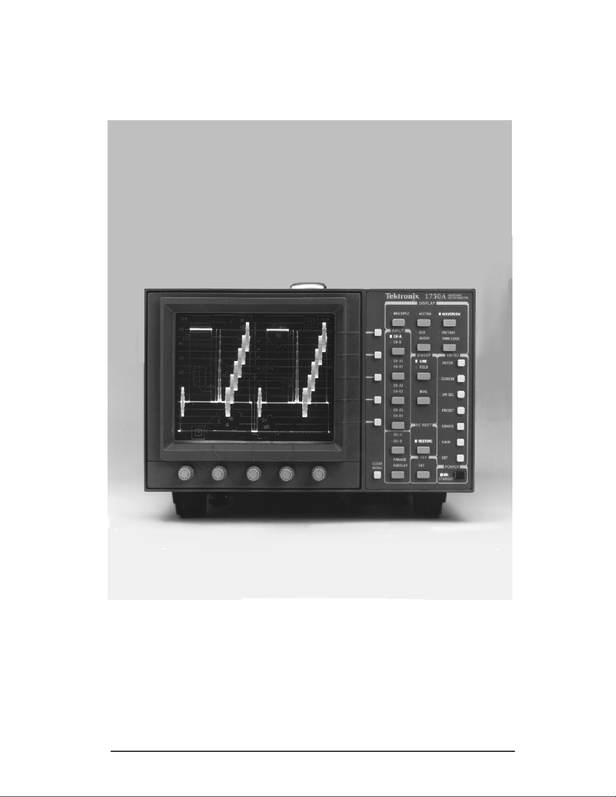
Preface
1750A Waveform / Vector Monitor.
1740A/1750A Series Waveform/Vector Monitor User Manual
xiii
Page 18

Preface
Contacting Tektronix
Phone 1-800-833-9200*
Address Tektronix, Inc.
Department or name (if known)
14200 SW Karl Braun Drive
P.O. Box 500
Beaverton, OR 97077
USA
Web site www.tektronix.com
Sales
support
Service
support
Technical
support
* This phone number is toll free in North America. After office
hours, please leave a voice mail message.
Outside North America, contact a Tektronix sales office or
distributor; see the Tektronix web site for a list of offices.
1-800-833-9200, select option 1*
1-800-833-9200, select option 2*
Email: techsupport@tektronix.com
1-800-833-9200, select option 3*
6:00 a.m. -- 5:00 p.m. Pacific time
xiv
1740A/1750A Series Waveform/Vector Monitor User Manual
Page 19

Introduction
Page 20

Page 21

The 1740A/1750A--Series are combination waveform/vector
monitors in half-rack size packages. The 1740A--Series
provides all basic waveform monitor and vectorscope functions; the 1750A--Series provides the same functions with
SCH measurement capabilities added. The following products
are available:
Applications
Product Description
1740A / 1750A NTSC
1741A / 1751A PAL
1745A / 1755A NTSC / PAL (dual-standard)
Typical applications for these monitors include video signal
monitoring in camera control units, VTR bridges, production
switcher consoles, mobile vans and field production systems.
The 1740A--Series is well-suited for port able applications
where a small, lightweight monitor is needed, and SCH
capability is not required. It is appropriate for many VTR
bridge applications, providing remote control and 90/100 Hz
sweeps for D-2 servo observation.
The 1750A--Series is useful in the composite edit suite,
providing all 1740A--Series features, plus the Tektronix polar
SCH display to match color subcarrier-to-horizontal sync
timing and color framing among edit sources.
1740A/1750A Series Waveform/Vector Monitor User Manual 1-1
Page 22

Product Description
Features
H Composite or Component Waveform Monitoring
H Composite Vector Display
H Menu-Assisted Operation allows expanded feature set.
H Assignable cursors for time and voltage.
H Picture monitor mode for verifying signal source
H Stereo Audio Display
H Longitudinal time code display mode for editing applica-
tions
H SCH and Color Framing Display (1750A--Series only)
H External staircase from a camera control unit can be
selected remotely.
H Internal video filters provide specialized measurements,
with dual or triple filter modes available in
OVERLAY.
H Eight video inputs can be individually displayed or
selected in various combinations.
H Remote interface and serial RS232 interface.
Description of Features
Menu
A notable feature of these monitors is t he m enu-assisted
operation. An expanded feature set is possible through the
use of menus and multi-use controls and buttons. When the
operator selects a menu item, such as
CURSORS
label shows the current function of the controls.
, VARIABLE G AIN,orLINE SELECT, an on-screen
PARADE or
VOLTAGE/TIMING
1-2
Many instrument configurations that required moving internal jumpers or wire straps in the 1740/1750--Series monitors
are made through an on-screen menu in the 1740A/ 1750A-Series. The operator can also recal l up to 10 front-panel
setups through the
1740A/1750A Series Waveform/Vector Monitor User Manual
RECALL menu; 9 recalls are user-program-
Page 23

Product Description
mable and 1 is factory-programmed. The FILTER menu also
provides a choice of four filters in addition to flat. Two
combination filtering modes can be displayed in
PARADE. Refer to “Using the Menus” on page 3-5 for more
OVERLAY or
menu information.
CRT
The monitors have a bright, post-accelerated CRT with
lighted internal graticule. The parallax-free internal graticule
structure contains targets and markings for both the vector
and waveform functions. A white phosphorus CRT is optional; refer to page 1-6 for details.
The bright CRT allows use in high ambient light conditions,
such as those encountered in field production applications.
Calibrator
Vertical and horizontal instrument gain can be set using the
calibrator signal. The 1 Volt calibrator signal is available in
100 kHz and F
More Information
H Standard and optional accessories are listed in the
Accessories section, which follows this product de scription.
H Instrument options are listed on page 1-5.
H A complete listing of instrument specifications begi ns on
Appendix page A-1.
(color subcarrier) rates.
SC
1740A/1750A Series Waveform/Vector Monitor User Manual
1-3
Page 24

Product Description
1-4
1740A/1750A Series Waveform/Vector Monitor User Manual
Page 25

White phosphor CRT and power cord options are the only
options currently available for the 1740A/1750A--Series.
Field upgrade kits listed in this section can also be used with
these monitors.
Power Cord Options
Any of the following power cord options can be ordered for
the 1740A/1750A--Series. If no power cord option is specified, instruments are shipped with a North American 125 V
power cord and one replacement fuse.
Unless otherwise specified, power cords for use in North
America are UL listed and CSA certified. Cords for use in
areas other than North America are approved by at least one
test house acceptable in the country to which the product is
shipped.
Options
Option A1. Power, Universal Europe, 220 V/16 A
(Locking Power Cord)
Option A2. Power, United Kingdom, 240 V/15 A
(Power Cord)
Option A3. Power, Australia, 240 V/10 A
(Power Cord)
Option A4. Power, North America, 250V/10 A
(Power Cord)
Option A5. Power, Swiss, 240 V/6 A
(Power Cord)
1740A/1750A Series Waveform/Vector Monitor User Manual 1-5
Page 26

Options
CRT Options
The standard instrument is shipped with a P31 (green)
phosphor CRT installed. If Option 74 is ordered, the instrument is shipped with a P4 (white) phosphor CRT installed.
The Option 74 CRT part numbers are given in the service
manual, at the end of the Replaceable Electrical Parts List.
1-6
1740A/1750A Series Waveform/Vector Monitor User Manual
Page 27

Standard Accessories
These accessories are included with the product:
1 Manual, user: 1740A/1750A--Series
(070--8470--XX)
1 Cable assembly, power: United States and Japan
only (161--0216--XX)
1 Cable assembly, power: all other countries
(161--0066--XX)
1 Fuse, cartridge: 3AG, 2A, 250V, fast-blow
(159--0021--00)
4 Light bulbs: graticule scale (150--0168--00). See
page C-1 for replacement instructions.
Accessories
4 Air filters: fan (378--0335--00). See page C-1 for
replacement instructions.
This accessory is installed on the product:
1 CRT filter: smoke gray (378--0258--00)
Optional Accessories
Manual, service: 1740A/1750A/1760-- Series
(070--8469--XX)
Camera, C9 Option 20
Viewing Hood (016--0475--00)
Front-Panel Cover (200--3897--01)
1740A/1750A Series Waveform/Vector Monitor User Manual 1-7
Page 28

Accessories
Field Upgrade Kits
1700F00 Plain Cabinet — This plain metal half-rack
size cabinet is painted silver-gray. Ventilating holes in top,
bottom, and sides of the cabinet allow heat generated within
the instrument to dissipate.
1700F02 Carrying Case — This portable cabinet is
similar to the 1700F00, but has feet, carrying handle, flipstand, and front cover.
1700F05 Side-by-Side Rack Adapter — The
1700F05 allows the user to mount two half-rack width
instruments in a standard 19--inch rack.
1700F06 Blank Panel — If only one section of a
1700F05 is used, the 1700F06 Blank Panel can be inserte d in
the unused section to improve appearance and air flow.
1700F07 Utility Drawer — When only one side of a
1700F05 is used, this utility drawer can be installed in the
unused section to provide storage. The drawer opens and
closes freely, unless latched for transport.
Ordering — These items can be ordered with the monitor,
or purchased through a Tektronix field office or distributor.
When ordering, include both the name and number of the
Field Upgrade Kits.
Installation — Cabinet installation instructions begin on
page 1-12. Dimensional drawings are also shipped with each
cabinet. For more information, contact a Tektronix field
office or distributor.
1-8
1740A/1750A Series Waveform/Vector Monitor User Manual
Page 29

Installation
Unpacking
Save the shipping carton and packing materials (including
anti-static bag) in case it becomes necessary to ship the
instrument to a Tektronix Service Center for service or repair.
Accessories
Check that the following accessory items are included:
H User Manual
H Service Manual
Note: The Service Manual is an optional accessory
that must be ordered to be received.
H Power Cord
H Replacement Fuse Cartridge (1)
H Replacement Graticule Light Bulbs (4)
H Replacement Air Filters for Fan (4)
Repackaging for Shipment
If it becomes necessary to ship the instrument to a Tektronix
Service Center for service or repair, follow these instructions
for repackaging:
1. Attach a tag to the instrument showing: the owner,
complete address and phone number of someone at your
firm who can be contacted, the instrument serial number
and a description of the required service.
2. Package the instrument in the original packaging materials. If the original packaging materials are not available,
follow these directions:
1740A/1750A Series Waveform/Vector Monitor User Manual 1-9
Page 30

Installation
a. Obtain a carton of corrugated cardboard having
inside dimensions six or more inches greater than
the dimensions of the instrument. Use a shipping
carton that has a test strength of at least 275 pounds.
b. Surround the instrument with a protective bag
(anti-static preferred). For instruments which are
not in a cabinet, wrap a cardboard piece around the
bagged instrument to protect components.
c. Pack dunnage or urethane foam between the instru-
ment and the carton. If using Styrofoam kernels,
overfill the box and compress by closing the lid.
There should be three inches of tightly packed
cushioning on all sides of the instrument.
3. Seal the carton with shipping tape, industrial stapler, or
both.
Electrical Installation
Power Source
These monitors are designed to operate from a single-phase
power source having one of its current-ca rrying conductors at
or near earth ground (the neutral conductor). Only the line
conductor is fused for over-current protection. Systems that
have both current-carrying conductors live with respect to
ground (such as phase-to-phase on multiphase systems) are
not recommended as power sources. A protective ground
connection by way of the grounding conductor in the power
cord is essential for safe operation.
When power is supplied, line voltage will be
present in the instrument, even if the
is set to
STANDBY.
NOTE
POWER switch
1-10
1740A/1750A Series Waveform/Vector Monitor User Manual
Page 31

Installation
WARNING
Mains Frequency and Voltage Range
The 1740A/1750A--Series monitors operate at 50 and 60 Hz,
over the range of 90--250 Volts, without operator adjustment.
Remote Connector
The rear-panel REMOTE connector is a 25-pin, D-type connector. It provides the input for
horizontal, and remote sync. It also accepts the input signals
for external blanking, time code, stereo L and R audio. TTL
signal or ground closure to designated pins will enable
Staircase, External Horizontal, or Remote Sync displays.
Eight front-panel setups can also be stored and recalled
through the
REMOTE connector. REMOTE connector pin
assignments begin on page B-1.
RGB/YRGB staircase, external
RS232 Connector
The rear-panel RS232 connector is a 9-pin subminiature
D-type connector that provides a serial inte rface for remote
control. The RS232 pin assignments are given on page B-1.
The RS232 interface is not supported at the time of this
printing.
Operational Changes
No operational modifications are made to these monitors
through internal jumper settings. Input coupling,
STORER
clamp time, RGB/YRGB selections and other similar
configurations are changed through the on-screen menu.
Instrument configuration is described on page 3-18.
DC RE-
1740A/1750A Series Waveform/Vector Monitor User Manual
1-11
Page 32
Installation
Mechanical Installation
All qualification testing was performed with a Tektronix
1700F00 cabinet installed. To guarantee compliance with
specifications, the instrument should be operated in a cabinet
or rackmount adapter. The Tektronix 1700F00, 1700F02,
and 1700F05 provide the proper electrical environment for
the instrument, supply adequate shielding, minimize handling
damage, and reduce dust collection within the instrument.
Cabinets
WARNING
Do not lift a cabinetized instrument without installing the mounting screws. There is nothing to hold
the instrument in the cabinet if it is tipped forward.
The 1700F00 is a plain cabinet designed for permanent
installations, and the 1700F02 is a portable cabinet with
handle, feet, flipstand, and front cover. Ordering information
is given on page 1-8.
Custom Installation
For applications such as consoles, the instrument can be
mounted with front molding flush or protruding from the
console. In both cases, allow approximately three inches of
rear clearance for
mount the instrument safely, attach it to a shelf strong
enough to hold its weight, using the four 0.156-inch diameter
holes in the bottom of the 1700F00 cabinet. Refer to the data
sheet included with the cabinet for hole locations.
BNC and power-cord connections. To
1-12
1740A/1750A Series Waveform/Vector Monitor User Manual
Page 33

Installation
Rackmounting
The 1740A/1750A--Series monitors are half-rack width and
three rack units high. They require approxim ately three
inches of rear clearance for power cord and cable connections, and 20 inches in front of a rack for installation and
removal of the instrument.
The optional 1700F05 rack adapter allows two Tektronix
half-rack instruments to be mounted side-by-side in a rack.
It is adjustable so that the instrument can be closely aligned
with other equipment in the rack. If only one section of the
rack adapter is used, a 1700F06 blank panel or 1700F07
utility drawer can be inserted in the unused secti on. Ordering information is given on page 1-8.
1740A/1750A Series Waveform/Vector Monitor User Manual
1-13
Page 34

Installation
1-14
1740A/1750A Series Waveform/Vector Monitor User Manual
Page 35

Instrument Configuration
Focus, scale illumination, signal intensity, readout int ensity,
and trace rotation are set through the CRT menu.
Several instrument operating parameters can be set through
CONFIG menu.
the
Instructions for using these menus begin on page 3-18.
1740A/1750A Series Waveform/Vector Monitor User Manual 1-15
Page 36

Instrument Configuration
1-16
1740A/1750A Series Waveform/Vector Monitor User Manual
Page 37

Getting Started
Page 38

Page 39

Front-Panel Controls
The following is an overview of front-panel controls.
Figure 2-2 shows the 1740A front panel and Figure 2-3
shows the 1750A front panel.
C o n t r o l s --- S w i t c h e s --- L E D s
H All front-panel controls are the continuous action
type, and all front-panel buttons are push-and-re-
lease toggle switches.
H Green LEDs light to indicate the current switch
selection.
AT A GLANCE
POWER
H ON/STANDBY turns the instrument on or to standby
status. An LED indicates when power is on.
WARNING
If an appropriate power source is supplied to t his
instrument, line voltage will be present, even when
STANDBY mode. Do not operate the instrument
in
without a cabinet or rack adapter such as those
described on page 1-8; serious injury could result.
Instrument Reset
Certain conditions may cause the 1740A/1750A-- Series
instrument front-panel controls to become locked. Reset as
follows:
1740A/1750A Series Waveform/Vector Monitor User Manual 2-1
Page 40
At A Glance
H Turn off instrument power.
H Depress and hold the
CLEAR MENU and WAVEFORM
buttons while you turn instrument power on again. Hold
both buttons in until the instrument returns to its normal
operating state.
H If this reset does not unlock the controls, contact your
Tektronix field office or call Tektronix at the phone
number listed in the front of this manual.
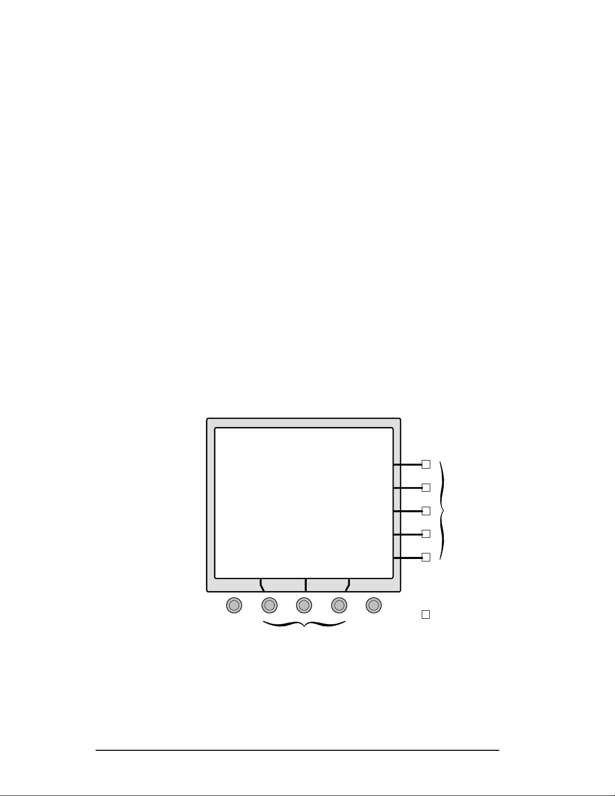
Multi-Use Controls
H The center three controls located under the CRT
have functions assigned and labeled through the
on-screen menus and readouts. These controls will
be referred to as Bezel Controls. See Figure 2-1.
H Five small buttons along the right side of the CRT
enable users to make selections when on-screen
menus are in use. These buttons will be referred t o
as Bezel Buttons.
VERTPOS
Three Bezel Controls
Figure 2-1. Multi-Use Bezel Controls and Buttons.
2-2
1740A/1750A Series Waveform/Vector Monitor User Manual
HORIZPOS
CLEAR
MENU
Five
Bezel
Buttons
Page 41

At A Glance
WAVE F O R M /
VECTOR MONITOR
DISPLAY
1740A
VECTOR WAVEFORM
MULTIPLE
PICTURE
INPUT
TIME CODE
AUDIO
CH-A
CH-B
MENUSWEEP
LINE
CH-A1
FILTER
CURSOR
LIN SEL
PRESET
CONFIG
GAIN
FIELD
CH-B1
MAG
CH-B3
CH-A2
CH-A3
CH-B2
RESTORE
DC REST
A 123
B 123
POWER
CRT
ON/
STANDBY
REF
EXT
PARADE
OVERLAY
MENU
CLEAR
HORIZ POS
Figure 2-2. 1740A Front Panel.
1740A/1750A Series Waveform/Vector Monitor User Manual
VERT POS
2-3
Page 42

At A Glance
WAVE F O R M /
VECTOR MONITOR
DISPLAY
1750A
VECTOR WAVEFORM
MULTIPLE
PICTURE
SCH
INPUT
TIME CODE
AUDIO
CH-A
CH-B
MENUSWEEP
FILTER
LINE
CH-A1
CURSOR
LIN SEL
PRESET
CONFIG
GAIN
FIELD
CH-B1
MAG
CH-B3
CH-A2
CH-A3
CH-B2
RESTORE
DC REST
A 123
B 123
POWER
CRT
ON/
STANDBY
REF
EXT
PARADE
OVERLAY
MENU
CLEAR
HORIZ POS
Figure 2-3. 1750A Front Panel.
2-4
1740A/1750A Series Waveform/Vector Monitor User Manual
VERT POS
Page 43

At A Glance
POSITION
H VERT POS allows the signal display to be moved
vertically. Offsets for channels A2/A3 and B2/B3
are enabled through the
CONFIGURE menu.
DISPLA Y
H WAVEFORM provides voltage vs. time display of the
video signal.
H
VECTOR presents an XY plot of demodulated chromi-
nance phase and amplitude.
AUDIO amplitude and phase is monitored using a
H
calibrated
SCH provides a vector display of the subcarrier-to-
H
horizontal-sync phase relationship.
X/Y Lissajous display.
PICTURE allows the operator to verify the signal
H
source.
TIME CODE provides monitoring of longitudinal time
H
code in a frame-rate display.
MULTIPLE allows simultaneous selection of multiple
H
DISPLAY modes.
SWEEP
Sweep buttons are used to select the waveform sweep rate.
LINE/FIELD sequences through four sweep rate
H
selections: one line, two line, one field, and two
field.
MAG turns on the sweep magnifier. See page 3-4.
H
DC REST
H RESTORE turns DC Restorer on or off. The DC
Restorer speed and clamp point are selected through
CONFIGURE menu, shown on page 3-18.
the
1740A/1750A Series Waveform/Vector Monitor User Manual
2-5
Page 44

At A Glance
REF
H EXT toggles between external reference (EXT LED
on) and internal reference. Internal reference can be
configured for component operation, and two
external reference inputs can be designated for
dual-standard instruments. See the
CONFIGURE men
on page 3-18.
INPUT
H Selecting a front-panel input causes the signal that is
input to the corresponding rear-panel connector to
be displayed on screen.
H Without
PARADE or OVERLAY select ed, only one
input selection can be made at a time. Each input
channel button (including
between
A and B, and is cancelled when another
A123 / B123) toggles
input button is pressed.
H With
PARADE or OVERLAY selected, multiple input
selections can be made; input buttons select
both, or off, and do not cancel each other.
A123
A123 provides a side-by-side display of the CH-A1,
CH-A2, and CH-A3 inputs (B123 displa ys the CH-B1,
CH-B2, and CH-B3 inputs). Selecting A123or B123
turns off all other input channels. When PARAD E or
OVERLAY is selected, A123 and B123 can be displayed
together and in combination with other inputs.
ARADE
P
A, B,
2-6
PARADE displays up to four input channels side-by-
side, with any additional inputs overlaid. Selecting
PARADE displays the input channel(s) last selected
PARADE, allowing a custom configuration of
for
inputs. In
PARADE mode , the LINE/FIELD button
offers only two choices: one line and one field.
1740A/1750A Series Waveform/Vector Monitor User Manual
Page 45

At A Glance
OVERLAY
OVERLAY provides an overlaid display of all se-
lected inputs.
MENU
Push the desired menu button to enter that menu and enable
the associated functions. Push the button again to exit the
menu and disable the function. Refer to page 3-5 for more
information about using menus.
FILTER allows choice of flat or filtered display of the
H
waveform signal.
CURSOR enables timing cursors, voltage cursors,
H
and markers for the waveform display. Polar cursors
and markers are available for the vector display.
LIN SEL allows the selection of a single line or group
H
of lines for display.
PRESET allows the user to store and recall up to 9
H
front-panel setups. One additional recall is factory
pre-programmed. Presets one through eight can also
be accessed remotely.
CONFIG allows the user to configure several operat-
H
ing parameters, such as input coupling, dc restorer
speed, and internal reference designation.
GAIN provides selection of X1, X5, X10, and variable
H
gain.
CRT menu allows adjustment of CRT focus, signal
H
intensity, and trace rotation.
CLEAR MENU turns off the selection portions of the
H
menu readout. When
CLEAR MENU hasbeenusedto
clear a menu readout, push the menu button once to
reinstate the readout, and once again to exit the
menu.
1740A/1750A Series Waveform/Vector Monitor User Manual
2-7
Page 46

At A Glance
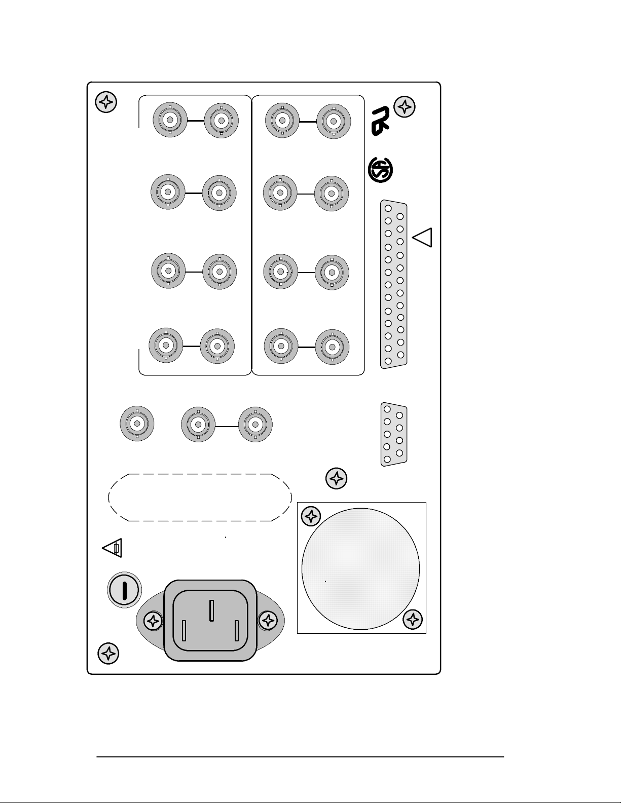
Rear-Panel Connectors
The following is an overview of rear-panel connectors.
Figure 2-4 shows the 1750A rear panel.
Loop-Through Inputs
H INPUTs A,A1,A2,A3,B,B1,B2,andB3 are passive
loop-through video inputs, compensated for 75 Ω.
The front-panel
which channel(s) are displayed. The eight inputs can
be configured for composite or component video
signals.
EXT REF is a 75 Ω compensated loop-through
H
synchronization input. Internal or external refe rence
is selected through the front-panel
the LED lights to show when external is selected.
The instrument will operate from external references
of composite video or black burst.
INPUT switch settings determine
REF EXT switch;
Outputs
H PIX OUT is a 75 Ω compensated output of the video
signal selected by the front-panel
This signal has bright-up in
LINE SELECT mode, and
is used to drive a picture monitor.
INPUT switches.
PIX OUT strobe is
not present below line 11.
Multi-Pin Connectors
H REMOTE is a 25-pin subminiature D-type connector
which uses TTL signal or ground closures to provide
remote control of many front-panel func tions. For
more information, see page 3-25 and page B-1.
RS232 is a 9-pin subminiature ‘D-type connector that
H
provides a serial interface for remote control. The
RS232 interface is not supported at the time of this
writing.
2-8
1740A/1750A Series Waveform/Vector Monitor User Manual
Page 47

At A Glance
Fuse
H The instrument’s mains fuse should be replaced only
with a 250V, 2A, F-type cartridge fuse. A replace-
ment fuse is included with the instrument.
AC Power
H The AC POWER plug is a standard ac plug receptacle
for 120 or 240 Vac power mains. The plug is
compatible with any of the power cord options
available with the 1740A/1750A--Series.
Fan Filter
H Four replacement air filters for the fan are included
with the instrument. Refer to page C-1 for replace-
ment and cleaning instructions.
1740A/1750A Series Waveform/Vector Monitor User Manual
2-9
Page 48
At A Glance
AA1
BB1
113
14
!
A2
DIE IN DIESEM GERAT ENTSTEHENDE ROHTGENSTRAHLUNG IST
75 OHM LOOP--THROUGH COMPENSATED
BESCHLEUNIGUNGSPANNUNG KLEINER ALS 20KV.
AUSREICHEND AB GESCHIRMT.
A3
B2
REMOTE
B3
25
1
6
TO AVOID
WARNING
ELECTRICAL SHOCK,
FUSE
REPLACE
PIX
OUT
WITH
F TYPE
250V 2A
110 VA MAX
90--- 250V
50/60 HZ
EXT
REF
Figure 2-4. 1740A/1750A --- Series Rear Panel.
PROTECTIVE
GROUNDING
THE POWER COR D
EARTH GROUND.
CONDUCTOR MUST
BE CONNECTED TO
5
RS232
9
2-10
1740A/1750A Series Waveform/Vector Monitor User Manual
Page 49

Operator’s Checkout
Procedure
Before proceeding, read At A Glance startingonpage2-1.
This procedure is designed for operator familiarization and
for checking basic instrument operation (not measurement
quantities or specifications). All illustrations are of the
1750A unless otherwise noted.
If performing this procedure reveals improper instrument
operation, first check the operation of the associated equipment. If the associated equipment is operating normally,
refer the 1740A/1750A--Series to qualified service personnel
for repair or adjustment.
Required Equipment
The following equipment is required to perform this procedure:
1. Television Signal Generator with:
Composite Color Bars
For example: TEKTRONIX TSG 130 Series Signal
Generator.
2. Coaxial Cable, 75Ω (5)
For example: 42-inch RG59U (Tektronix Part No.
012-0159-00)
3. 75Ω T erminators, End-line (4)
For example: (Tektronix Part No. 011-0102-00)
Initial Equipment Connections
H Connect the 1740A/1750A--Series to an appropriate AC
power source.
1740A/1750A Series Waveform/Vector Monitor User Manual
2-11
Page 50
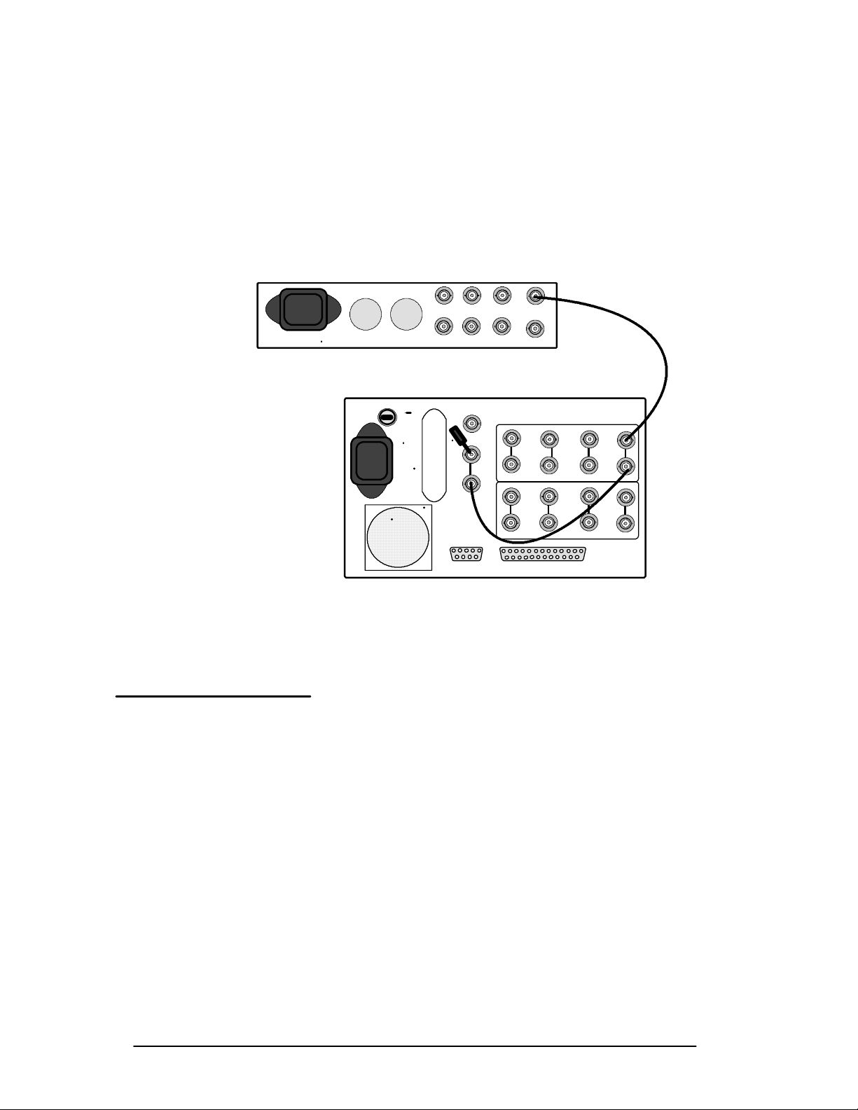
Operator’s Checkout Procedure
H Connect the generator NTSC output (COMPOSITE for
TSG131) to the CH-A input. Connect the CH-A loopthrough to the EXT REF input and connect a 75Ω
terminator to the EXT REF loop-through. See
Figure 2-5.
TSG 130
Y
EXT
REF
B-YR-Y
Y
NTSC
NTSC
A3
B3
A1A2
B2
1750A
Figure 2-5. Equipment hook-up for Operator’s Checkout Procedure.
A
BB1
Procedure
2-12
1. Initialize the Front-Panel Controls
Enter the
button corresponding to
PRESET menu and select FACTORY. Press the bezel
RECALL. The front-panel controls
are now set to the factory preset (described on page 3-16),
and the
instrument is in the
INPUT
PRESET menu is automatically exited. Notice that the
WAVEFORM display mode with the CH-A
displayed in two-line sweep.
2. Adjust the Display
Use the
VERT POS and HORIZ POS controls to center the
display.
1740A/1750A Series Waveform/Vector Monitor User Manual
Page 51

Operator’s Checkout Procedure
Enter the CRT menu. DISPLAY will be outlined. Adjust the
bezel controls for optimum focus, graticule scale illumination, and signal intensity. Select
READOUT and adjust the
right bezel control for desired readout intensity. Select
TRACE and adjust the center bezel control for a level trace.
Exit the
CRT menu. The changes made while in the menu
remain in effect.
3. Input Channel Selection
Press the
EXT and PARADE buttons. Check that CH-A, CH-A1,
CH-A2, and CH-A3 inputs are selected.
The CH-A signal should appear on the left side of the CRT.
Move the generator signal (and EXT REF cable) to CH-A1.
The display should move to the right. Repeat this step until
the signal is connected to CH-A3 and the display is at the far
right-hand side of the screen.
Change the input selections to CH-B, CH-B1, CH-B2, and
CH-B3. Repeat the process of moving the generator signal.
4. Check Gain
The 1740A/1750A--Series internal calibrator can be used to
check instrument calibration. Select
CH-A input and set the
generator for NTSC Color Bars output.
Enter the configuration menu and select
the calibrator signal and note that the amplitude is 140 IRE
(1.0 V PAL), with one cycle per division. See Figure 2-6.
Select
VECTOR display mode. Note that the calibrator signal
overlays the compass rose. Return to
mode.
Exit the configuration menu. Note that the calibrator signal
is automatically turned off. (For more information on using
the calibrator signal, see page 3-21 and page 4-17.)
1740A/1750A Series Waveform/Vector Monitor User Manual
CALIBRATE. Turn on
WAVEFORM display
2-13
Page 52
Operator’s Checkout Procedure
10S/DIV
Figure 2-6. Calibrator display.
5. Gain Control
There are three calibrated vertical gain settings available (
X5,andX10), as well as an independent variable gain control.
Enter the
GAIN menu and select X5. Note that X5 is outlined
and the display is amplified. Select
outlined and the display is amplified again.
Select variable gain and use the right bezel control to adjust
the gain to the minimum and maximum settings.
Exit the
GAIN menu, then enter it again. Note that the vari-
able and X10 gain settings are restored. Exit the
Adjust the
VERT POS control to place the signal on baseline.
6. Select Timing Reference
The factory preset selects a two-line sweep. Note that
pressing the
selections: one-line, two-line, one-field, and two-field
sweeps. Return to the two-line sweep.
X1,
X10. Note that X10 is
GAIN menu.
LINE/BUTTON button will cycle through four
2-14
1740A/1750A Series Waveform/Vector Monitor User Manual
Page 53

Operator’s Checkout Procedure
Press the MAG button. The MAG indicator lights and a
1 S/Div sweep is displayed. Use the
view the magnified display, then t urn off the
HORIZ POS control to
MAG.(Seepage
3-4 for a list of sweep rates.)
7. Voltage and Timing Cursors
The 1740A/1750A--Series voltage, timing, and vector
cursors can be used to measure any portion of the displayed
signal.
Enter the
cursors;
CURSOR menu (factory preset selects voltage
VOLT is outlined on screen). The voltage cursors
appear as two dashed horizontal lines: cursor 1 has single
dashes and cursor 2 has double dashes. Use the left and
center bezel controls to adjust the cursors individually, or the
right control to move both cursors by the same amount
(TRACK). The voltage difference between the cursors is
displayed as ∆
ence point and press
point on the signal (use the
V. Align a voltage cursor with a signal refer-
MAG. The cursor is still at the same
HORIZ POS control if needed to
view the cursor).
Select timing cursors
(TIME). The timing cursors appear as
two vertical dashed lines: cursor 1 has single dashes and
cursor 2 has double dashes. The time difference between
them is displayed as ∆
together (
V+T). Note that when CONTROL is set to TIME, the
three bezel controls adjust timing cursors; when set to
T. Select voltage and timing cursors
VOLT,
they adjust voltage cursors.
Select markers
(MARK). The markers appear as three dashed
lines; marker 1 has long single dashes, marker 2 has double
dashes, and marker 3 has short dashes. Use the three bezel
controls to position the markers to a reference point on the
etched graticule (such as peak white, baseline, and sync tip).
Select
X5 gain and notice that the markers do not move.
These markers can be used to highlight desired features of
the waveform graticule.
Turn off the
Select
VECTOR display mode. The vector cursor menu is
displayed (
GAIN menu, then press the CURSOR button.
POLAR has been selected by the factory preset).
The polar cursor appears as cross hairs. Use the left bezel
1740A/1750A Series Waveform/Vector Monitor User Manual
2-15
Page 54

Operator’s Checkout Procedure
control to move the cursor away from grat icule cent er, and
the center bezel control to move the cursor around the graticule center point. Note that the amplitude and phase of the
cursor are displayed on screen.
Select
rotating the
markers appear as small numbered boxes. Set
MARK and set QUANTITY to 2. Move the marker by
AMPLITUDE knob. Note that the two graticule
CONTROL to 1
and use the left bezel control to move marker 1 away from
the graticule center. Use the center control to move the
marker around the graticule center point. Change
CONTROL
to 2. Use the bezel controls as for marker 1. Select X5 gain
and note that the markers do not move. These markers can
be used to highlight desired features of the vector graticule.
Return to
Exit the
that
WAVEFORM display mode.
CURSOR menu, then enter the menu again. Note
MARK is still selected and marker positions are un-
changed. Exit the menu. (For more information about using
the cursors, see page 3-8.)
8. Filter Selection
The 1740A/1750A--Series offers several filter selections for
the waveform display.
Ensure that the instrument is operating in waveform mode.
Enter the
preset). Select
FILTER menu (FLAT is selected by the factory
LUM filter. This provides a low-pass-filtered
display of the luminance portion of the signal. See
Figure 2-7.
Select
CHROM. This provides a bandpass-filtered display of
the chrominance portion of the signal. See Figure 2-8.
Select
F+L (FLAT plus LUM). The flat display is superimposed
on the luminance-filtered display (overlay is selected by the
factory preset). Press the appropriate bezel button (not the
front-panel
PARADE button) to sel ect parade. The flat display
is now on the left, followed by the luminance-filtered display.
2-16
1740A/1750A Series Waveform/Vector Monitor User Manual
Page 55
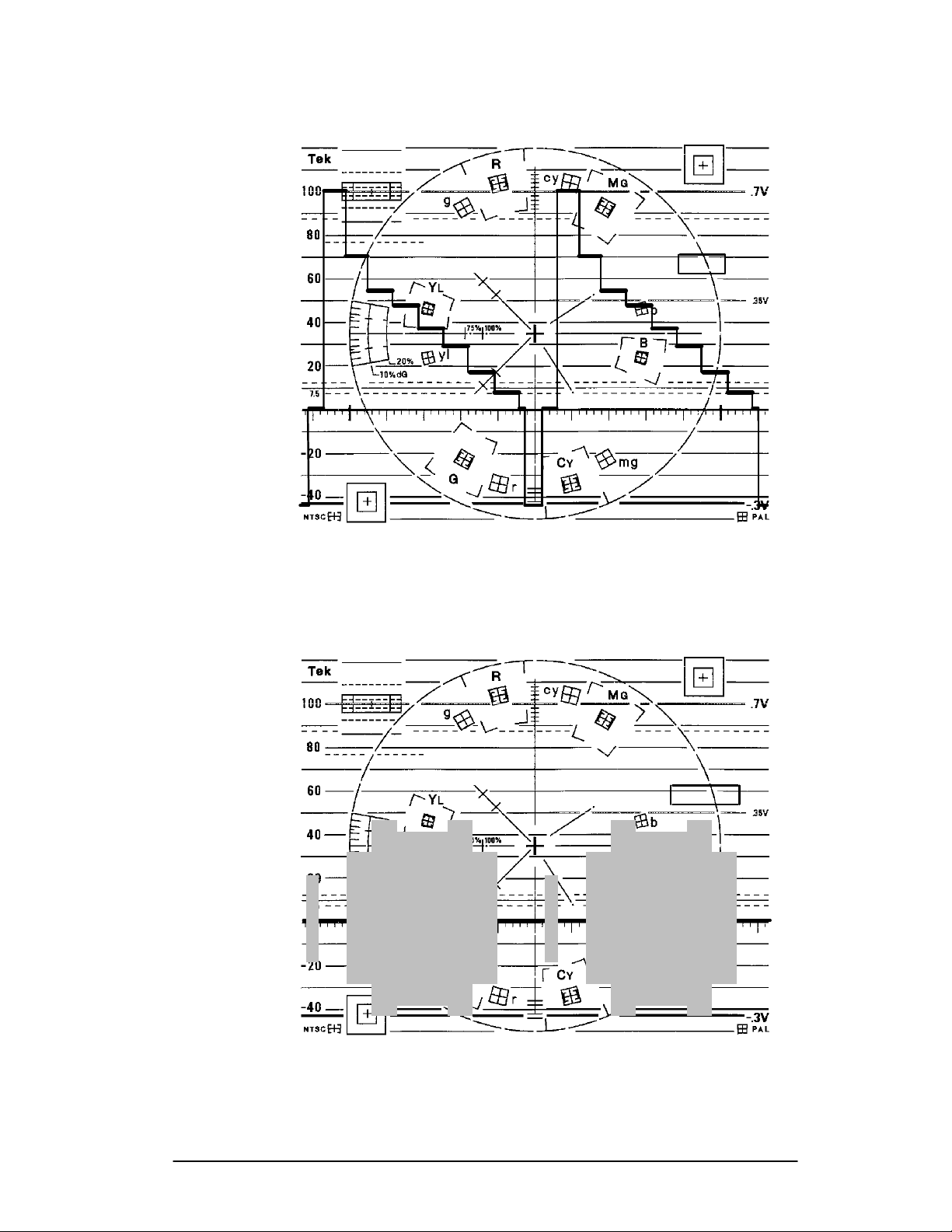
Operator’s Checkout Procedure
10S/DIV
FLAT
LUM
CHROM
DIFF
R--Y
SCH R -- Y
F+L
F+L+C
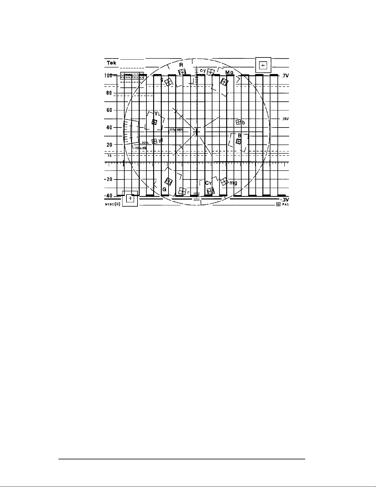
Figure 2-7. Two-Line LUM filter display of color bar signal.
10S/DIV
FLAT
LUM
CHROM
DIFF
R--Y
SCH R -- Y
F+L
F+L+C
Figure 2-8. Two-Line CHROM filter display of color bar signal.
1740A/1750A Series Waveform/Vector Monitor User Manual
2-17
Page 56
Operator’s Checkout Procedure
Select F+L+C (FLAT plus LUM plus CHROM). The display is
similar to the
signal added on the right.
F+L display, with the chrominance-filtered
Select
DIFF. Select the generator 5-step staircase signal. The
differentiated-step filtered display appears similar to
Figure 2-9.
Select
R --- Y. This provides a demodulated chrominance-ver-
sus-time display. Use the right bezel control to adjust vector
phase. See Figure 2-10.
Select
S C H R --- Y (1750A only). This provides a demodulated
SC/H sync-locked oscillator display, useful for viewing SC/H
variations versus time. A sample NTSC display is shown in
Figure 2-11. NTSC signals can be viewed in either line or
field sweeps. For PAL applications, view the signal in
two-field sweep (see Figure 2-12). Use the right bezel control
to adjust vector phase.
Exit the
filter selections are unchanged. Select
FILTER menu. Enter the menu again and note that the
FLAT . Exit the menu.
10S/DIV
CHROM
SCH R -- Y
F+L+C
Figure 2-9. Two-Line DIFF filter display of 5-step staircase signal.
FLAT
LUM
DIFF
R--Y
F+L
2-18
1740A/1750A Series Waveform/Vector Monitor User Manual
Page 57

Operator’s Checkout Procedure
FLAT
LUM
CHROM
DIFF
R--Y
SCH R -- Y
F+L
F+L+C
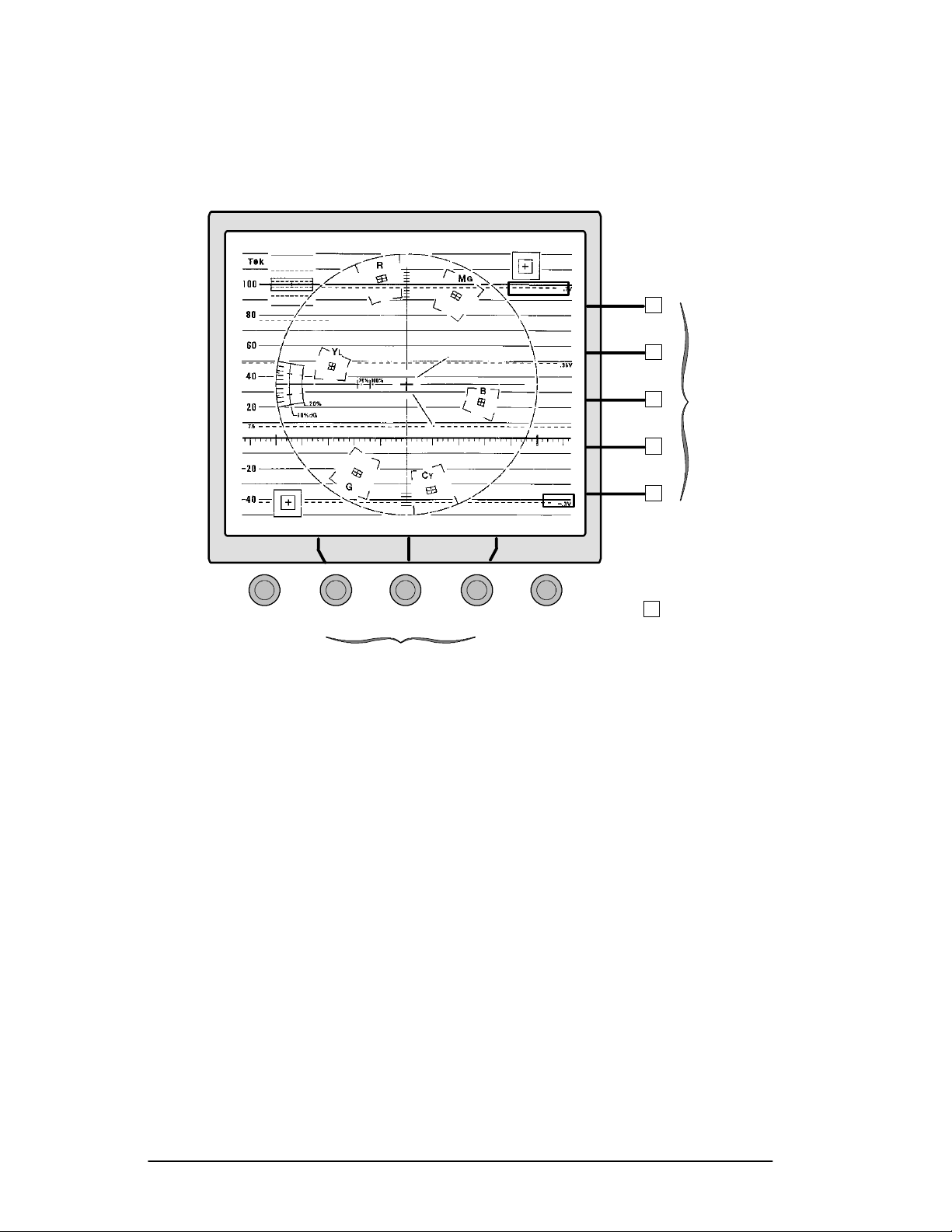
Figure 2-10. Two-Line R --- Y display of color bar signal.
VECTOR PHASE
FLAT
LUM
CHROM
DIFF
R--Y
SCH R -- Y
F+L
F+L+C
VECTOR PHASE
Figure 2-11. Two-Field SC/H R --- Y display (NTSC), showing proper SCH phase.
1740A/1750A Series Waveform/Vector Monitor User Manual
2-19
Page 58

Operator’s Checkout Procedure
FLAT
LUM
CHROM
DIFF
R--Y
SCH R -- Y
F+L
F+L+C
VECTOR PHASE
Figure 2-12. Two-Field SC/H R --- Y display (PAL), showing proper SCH phase.
9. Line Selection
Line select is available in the following display modes:
WAVEFORM, VECTOR, SCH (1750A--Series only), and PIC-
. Enter the LINE SELECT menu and turn the center bezel
TURE
control until the readout displays
ALL 131. In a two line
display, line 131 appears on the left, followed by line 132.
Select
field. Select
2FIELDsweep and note the intensified line in each
15H and note that 15 lines are now intensified in
each field (intensified portion appears wider). The readout is
ALL 131-- -- 145. See Figure 2-13.
now
2-20
1740A/1750A Series Waveform/Vector Monitor User Manual
Page 59

Operator’s Checkout Procedure
ALL131
-- -- 1 4 5
LINE SEL
Figure 2-13. Line Select display with 15H selected, in 2 FIELD sweep.
FIELD
ALL 1OF2
1H
15H
Select 1of2. Now only the first field has intensified lines,
and a
NEXT FIELD selection appears. Select NEXT FIELD and
note that the intensified lines now appear only in the second
field and the readout is
F2 131 F2 145.
1OF81OF4
Select MULTIPLE with WAVEFORM, VECTOR, and SCH (1750A--
Series only). Note that the displays appear in the order listed
here. Exit the line select menu. Enter the menu again and
note that the user settings are saved. Exit the menu.
10. Vectorscope Display
Select
VECTOR display mode. Adjust the right bezel control
to place the burst vector on the 180° graticule line. The
display should appear similar to Figure 2-14.
11. Picture Monitor Display
Select
PICTURE display mode. A picture monitor display of
the selected input signal appears. This can be used to visually identify the signal source. See Figure 2-15.
1740A/1750A Series Waveform/Vector Monitor User Manual
2-21
Page 60

Operator’s Checkout Procedure
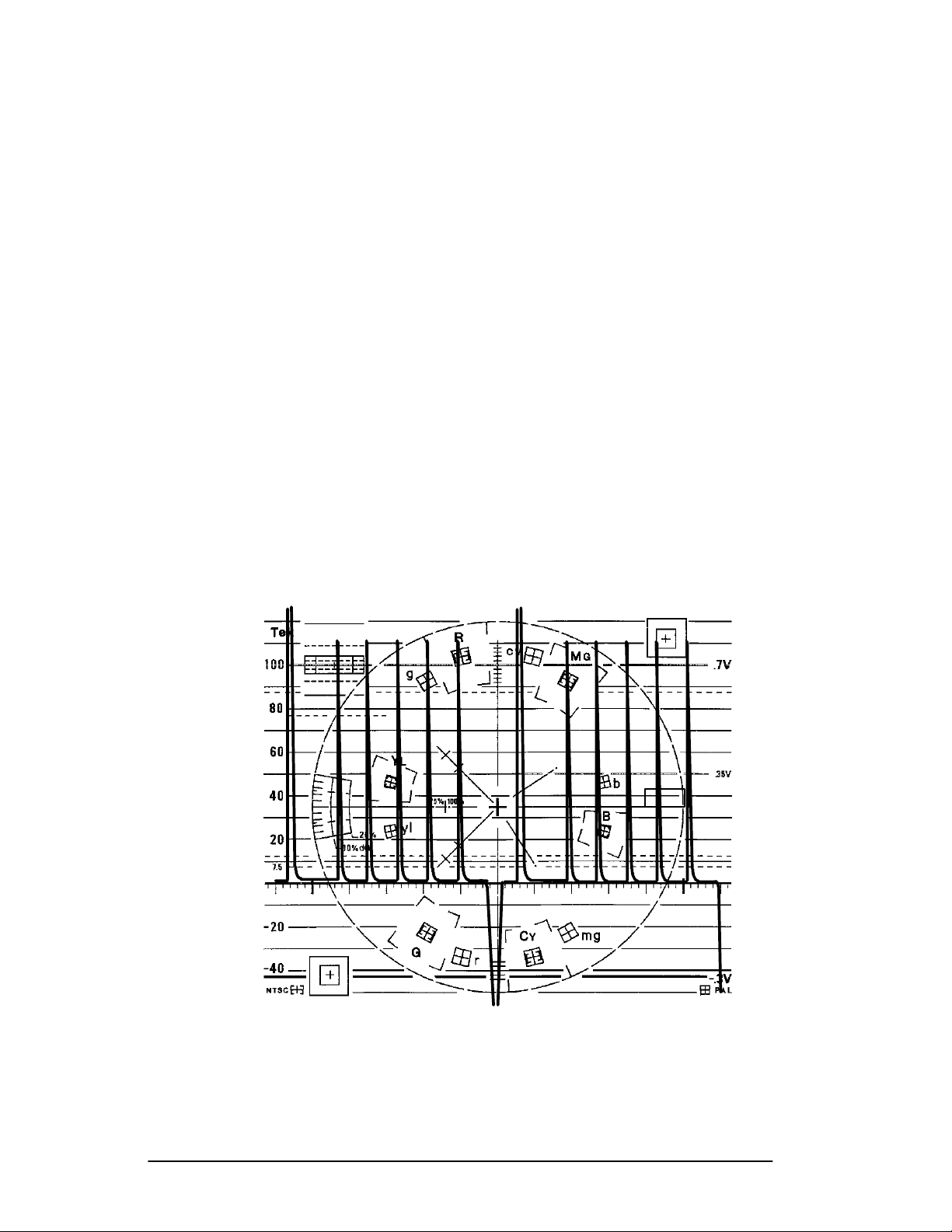
Figure 2-14. Vectorscope color bar display .
VECTOR PHASE
Figure 2-15. Picture mode display of color bar signal.
2-22
1740A/1750A Series Waveform/Vector Monitor User Manual
Page 61

Operator’s Checkout Procedure
12. Audio Display
To obtain an audio display, connect the left and right audio
signals to the rear-panel
REMOTE connector as follows: +Y to
pin 8, --Y to pin 9, +X to pin 10, and --X to pin 11. Select
AUDIO display mode.
An audio signal with no phase error appears as a straight line
extending from the audio box in the upper right corner of the
graticule to the box in the lower left. A signal with phase
error appears as an opening in a lissajous waveform. See
Figure 2-16.
13. SCH Display (1750A Only)
SCH display mode provides a vector display of the
The
subcarrier-to-horizontal-sync phase relationship. (SCH
measurements appear on page 4-10.)
For NTSC operation, verify that
select
SCH display mode. This provides a dual-dot display, as
shown in Figure 2-17. Select
REF is set to internal, then
EXT REF. This provides the
single-dot display, shown in Figure 2-18.
For PAL operation, the
REF selection does not affect the
display. A sample PAL display is shown in Figure 2-18.
Figure 2-16. Audio display with phase error.
1740A/1750A Series Waveform/Vector Monitor User Manual
2-23
Page 62

Operator’s Checkout Procedure
VECTOR PHASE
Figure 2-17. NTSC SC/H display with internal reference selected.
Figure 2-18. PAL SC/H display.
This concludes the Operator’s Checkout Procedure.
2-24
1740A/1750A Series Waveform/Vector Monitor User Manual
VECTOR PHASE
Page 63

Operation Basics
Page 64

Page 65

Functional Overview
The “Functional Overview” section describes the front- and
rear-panel functions in greater detail than the “At A Glance”
section.
Display Modes
The following display types are available:
H
H WA VEFORM
H AUDIO
H SCH (1750A--Series only)
H
VECTOR
PICTURE
H TIME CODE
H MULTIPLE displays
Vector
The vector mode presents an XY plot of demodulated chrominance phase and amplitude. The angle represents chrominance phase and the distance from the center represents
chrominance amplitude. A bezel control is assigned to adjust
VECTOR PHASE.
Waveform
The waveform monitor portion of the instrument provides a
voltage versus time display of the video signal. The selected
input can be displayed in one or two line, or one or two field
sweeps. In
can be selected and displayed. Multiple i nputs can be
displayed at the same time, or multiple filters can be applied
to one input for signal analysis.
LINE SELECT mode, identified lines of any field
TIME and VOLT AGE cursors
1740A/1750A Series Waveform/Vector Monitor User Manual 3-1
Page 66

Functional Overview
can be activated and positioned for reference or measurement.
are discussed on page 3-8.
Audio
Audio amplitude and phase is monitored using a calibrated
X/Y Lissajous display. The operator can verify that the
program audio will be properly reproduced on both monaural
and stereo receivers. Correct phasing betwe en two audi o
channels is quickly verified by the direction of the display.
SCH
SCH provides a vector display of the subcarrier-to-horizontal-
sync phase relationship. The burst vector and the phase of
the 50% point of the leading edge of sync are displayed.
LINE SELECT isdiscussedonpage3-14andCURSORS
Subcarrier-to-horizontal phase and color framing are displayed graphically in the polar
SCH display. Sync jitter over
the field is displayed as a moving sync vector dot. Correct
color framing can be verified by the position of the single
sync vector dot, relative to the color subcarrier vector when
the monitor is externally referenced.
SCH phase of the reference signal is separately sensed to
The
allow reliable color framing comparison. Using this method
of determining relative color framing eliminates the requirement for a precise horizontal timing match between the
reference and measured signals. An external color-field
identification input is also required.
Picture
The PICTURE mode allows the operator to verify the signal
source. In
marker identifies the selected line in the picture.
PICTURE mode with LINE SELECT on, a bright-up
3-2
1740A/1750A Series Waveform/Vector Monitor User Manual
Page 67

Functional Overview
Time Code
Longitudinal time code is monitored in a frame-rate display
to allow observation of amplitude, synchronization, and
phase with respect to reference vertical sync. Synchronization is confirmed by the stationary display and time code
phase is determined by horizontal position of the time code
sync word on the CRT.
Multiple
When MULTIPLE is pushed, any combination of front-panel
DISPLAY modes can be selected at the same time, with the
exception of
With
MULTIPLE selected, the SCH/AUDIO switch sequences
through
selected, the switch will also sequence to
mode must be on at all times.)
TIME CODE and PICTURE displays.
SCH, AUDIO, and both. If waveform or vector is a lso
OFF. (At least one
When exiting
previous (non-
MULTIPLE again, the previous MULTIPLE display settings will
be restored.
Displaying a Signal
Inputs
There are eight rear-panel loop-through inputs, whi ch may
eliminate the need for an external routing switcher. The inputs can be displayed singly or in combination.
Without
tion can be made at a time. Each input channel button (including
cancelled when another input button is pressed.
With
displayed in combination. Pushing an input channel button
sequences through the labeled channels, both, then off. Pushing another input button does not cancel the current selection, but adds to it. To return to “single input” operation,
push the
longer lighted).
PARADE or OVERLAY select ed, only one input selec-
A123 / B123) toggles between A and B, and is
PARADE or OVERLAY select ed, the input channels can be
PARADE / OVERLAY button until it is off (LED is no
MULTIPLE, the instrument will return to the
MULTIPLE) display settings. When entering
1740A/1750A Series Waveform/Vector Monitor User Manual
3-3
Page 68

Functional Overview
Inputs A1, A2, A3, and B1, B2, B3 aredesignedtobeusedas
three-wire inputs for component signals.
A123 / B123
Selecting A123 provides a side-by-side display of the CH-A1,
CH-A2,
CH-B3 inputs). This is designed for monitoring component
signals.
Parade
Selecting PARAD E displays t he input c hannels last selected
for
PARADE mode, the LINE/FIELD button offers only two choices:
one line and one field. Up to four channels can be displayed
side-by-side; additional channels are overlaid.
and CH-A3 inputs (B123 displays the CH-B1, CH-B2, and
PARADE, allowing a custom configuration of inputs. In
Overlay
OVERLAY superimposes the selected input signals. The LINE/
FIELD
button remains a four-way toggle, providing one line,
two line, one field, and two field displays.
Sweep
Sweep buttons are used to select the waveform sweep rate.
LINE/FIELD toggles through four sweep rate selections: one
line, two line, one field, and two field. In
LINE/FIELD button becomes a two-way switch, toggling be-
tween line and field.
The sweep rate is displayed in the upper right corner of the
CRT (for field-rate sweeps, 1F or 2F is displayed).
The
MAG button is used with LINE/FIELD to provide horizontal
magnification of each rate as follows:
H One line magnified = 200 ns/division
PARADE mode, the
3-4
H Two line magnified = 1 µs/division
H One field or two field magnified = approximately
X20 magnification.
1740A/1750A Series Waveform/Vector Monitor User Manual
Page 69

Using the Menus
General menu information here is followed by detailed
information about each menu:
PRESET, CONFIG, GAIN
parameters, see
CONFIG and CRT menu information.
General Menu Information
Push the desired menu button to obtain an on-screen menu
readout.
Multi-Use Bezel Controls and Buttons
Menu selections appear along the right side of the screen.
Descriptive labels, when present, appear in
tual selections appear in
selection outlined. Use the five buttons along the right side of
the CRT (referred to as bezel buttons) to change the selections.
and CRT. To set instrument operating
FILTER, CURSOR, LIN SEL,
ITALIC text. Ac-
STANDARD text, with the present
The center three controls under the CRT are referred to as
Left, Center, and Right bezel controls. Control functions
vary with menu choice; a readout just above each active control shows its present function. These controls are used as
variable analog controls to set values such as phase, amplitude, and intensity. The left control is also used to select
categories within the
Figure 3-1 shows the bezel controls and buttons.
CONFIG menu.
Moving Between Menus
Selecting a second menu removes the present menu display,
but the functions typically remain active (with the menu LED
remaining lighted to show this state). To reinstate a menu
display, push that menu button again.
1740A/1750A Series Waveform/Vector Monitor User Manual 3-5
Page 70
Using the Menus
CRT, PRESET, and CONFIG menus will be exited completely
when another menu button is pushed.
DISPLAY
READOUT
TRACE
Bezel
Buttons
TEST
ON OFF
FOCUS SCALE INTENSITY
VERTPOS
Left Center Right
Bezel Controls
HORIZPOS
CLEAR
MENU
Figure 3-1. The CRT menu, showing bezel controls and bezel buttons.
Clear Menu
Push CLEAR MENU to clear part of the menu display, but leave
essential readout elements such as control assignments and
measurement readouts. (The menu LED remains lighte d to
show this state.) Push the menu button to bring back the full
display.
CRT, PRESET, and CONFIG menus will be exited completely
when
CLEAR MENU is pushed.
3-6
Exiting a Menu Function
To exit a menu function while its display is present, push that
menu button. (The menu button is functioning as an on-off
toggle switch). If the menu display is not present, but the
1740A/1750A Series Waveform/Vector Monitor User Manual
Page 71

menu function is still in effect (LED is lighted), push the
menu button to bring back the full display, then push it again
to exit the menu.
Filter Menu (WAVEFORM Mode Only)
FILTER menu is available for WAVEFORM mode only.
The
Note that the instrument must be in
cess the R--Y displays. When the
WAVEFORM mode, an on-screen menu allows the following
selections. T he be zel buttons are self-cancelling.
FLAT — provides flat (normal) response.
H
LUM — provides a low-pass response to display the
H
luminance portion of the composite video signal.
Using the Menus
WAVEFORM mode to ac-
FILTER button is pushed in
CHROM — provides bandpass response centered on
H
the chrominance subcarrier frequency, and displays
frequencies around the subcarrier frequency.
DIFF — is a differentiated step filter (linearity steps
H
are translated into impulses for amplitude compa ri-
son).
R--Y — selects demodulated chrominance-versus-
H
time display. The chrominance is demodulated on
the R--Y (V) axis when burst is lined up on the
normal axis. The
VECTOR PHASE control can adjust
the demodulator phase to any axis.
SCH R--Y (1750A --Series Only) — demodulates the
H
SCH sync-locked oscillator. This display is useful
for viewing SCH variations versus time.
F+L—displays the video signal both flat and
H
luminance filtered. The display is in parade or
overlay mode, as selected through the on-screen
menu. When
PARADE is selected, the flat display is
on the left.
1740A/1750A Series Waveform/Vector Monitor User Manual
3-7
Page 72

Using the Menus
Cursor Menu
Press the CURSOR menu button to enter the cursor menu.
Cursors are available for
VECT+WFM DISPLAY m odes.
Vector Cursor Control
H F+L+C— displays the video signal flat, lumi-
nance filtered, and chrominance filtered. The signal
is displayed in parade or overlay mode, as selected
through the on-screen menu. When
PARADE is
selected, the flat display is on the left, with the
chrominance-filtered display on the right.
VECTOR, WAVEFORM, and
In VECTOR display mode, a bezel button is used to select polar cursors
(POLAR) or markers (MARK). The polar cursor ap-
pears as crosshairs, as shown in Figure 3-2. The left bezel
control is used to adjust cursor amplitude, and the center control adjusts cursor phase. The right bezel control adjusts the
phase of the vector signal.
When Vector markers are selected, additional readouts appear, allowing the user to select the quantity of markers that
will be present (1 through 8), and which of the se markers is
currently controlled by the bezel controls. The left bezel
control adjusts the amplitude of the selected marker, and the
center bezel control adjusts its phase. The right bezel control
adjusts the phase of the vector signal.
3-8
1740A/1750A Series Waveform/Vector Monitor User Manual
Page 73

Using the Menus
AMPL
75.0IRE
AMPLITUDE PHASE VECTOR PHASE
VERTPOS
Left Center Right
Figure 3-2. The VECTOR CURSOR menu.
PHASE
145.0°
VEC CURSO R
POLAR
MARK
HORIZPOS
CLEAR
MENU
Waveform Cursor Control
In WAVEFORM display mode, the bez el buttons are used to
select timing cursors
voltage and timing
cursor menu is shown in Figure 3-3.
H When voltage cursors are selected (
bezel control is used to adjust the vertical position
of the first voltage cursor, and the center bezel
control adjusts the second voltage cursor. The right
bezel control is used to move the vertical position of
both cursors vertically, in tandem. The readout
shows the voltage difference (positive or negative)
between the two cursor positions, up to four signifi-
cant digits.
(TIME), voltage cursors (VOLT), both
(V+T), or markers (MARK). The Waveform
VOLT), the left
∆V
1740A/1750A Series Waveform/Vector Monitor User Manual
3-9
Page 74

Using the Menus
H When timing cursors are selected (TIME), the left
bezel control is used to adjust the horizontal position
of the first timing cursor, and the center control
adjusts the horizontal position of the second timing
cursor. The right bezel control moves both cursors
horizontally, in tandem. The readout
∆T shows the
time difference (positive or negative) between the
two cursor positions, up to four significant digits.
H When markers are selected
(MARK), the left bezel
control is used to adjust the horizontal position of
the first marker line, the center bezel control adjusts
the second marker, and right bezel control adjusts
the third marker.
H When both voltage and timing cursors are selected
V+T), a control assignment appears on the screen.
(
The bezel button is used to assign the control to
voltage or timing cursors. The bezel controls work
the same as for the individual timing and voltage
cursor modes. Both voltage and timing readouts are
present.
∆ V
700 mV
WFM CURSO R
VOLT
TIME
MARK
VOLT1 VOLT2 TRACK
VERTPOS
Left Center Right
Figure 3-3. The WAVEFORM CURSOR menu.
3-10
1740A/1750A Series Waveform/Vector Monitor User Manual
V+T
HORIZPOS
CLEAR
MENU
Page 75

Using the Menus
Voltage Cursor 1
Voltage Cursor 2
Timing Cursor 1
Timing Cursor 2
VERTPOS
∆ V
700 mV
WFM CURSO R
VOLT
TIME
MARK
V+T
VEC CURSO R
POLAR
MARK
CONTRO L
VOLT
TIME
VOLT1 VOLT2 TRACK
HORIZPOS
Figure 3-4. The VECTOR+WFM CURSOR menu with V+T selected.
CLEAR
MENU
Vector + Waveform (Multiple)
If MULTIPLE is pressed and both VECTOR and WAVEFORM dis-
plays are selected, menus for all cursor types will be displayed. See Figure 3-4. All cursor functions are available in
this mode (the top three bezel buttons are self-cancelling).
Bezel control assignments are the same as for the individual
modes.
Using the Cursors
With Vector Display
Vector cursors are available when a composite vector display
is selected. To use vector cursors, operate in
TOR+WAVEFORM
VECTOR or VEC-
mode and press the CURSOR MENU button.
1740A/1750A Series Waveform/Vector Monitor User Manual
3-11
Page 76

Using the Menus
There are two vector cursor displays: POLAR and MARK.
(The VECTOR PHASE bezel control continues to adjust the
phase of the signal
.)
Polar Cursors can be used to measure the amplitude and
phase of the chrominance signal. When
position the cursor (cross hairs) with the
PHASE bezel controls, and view the amplitude and phase
POLAR is selected,
AMPLITUDE and
readouts at the top of the screen. See Figure 3-2. The cursor
zero amplitude point is the center point of the graticule. Using the amplitude control to move the cursor out from the
center increases the amplitude. Adjusting the cursor phase
will rotate the cursor around the center point, with the zero
phase point being the B--Y (U) axis. The amplitude readout
can be set for m
V or IRE values through the CONFIG menu,
described on page 3-18.
When the gain or position of the signal is changed, the polar
cursors maintain their relationship with the signal.
When
CLEAR MENU is pressed, the POLAR / MARK choice on
the right side of the screen will be removed, but the bezel
controls will still be active and cursor measurements can still
be made. When another menu is selected, the bezel controls
may be reassigned to the new menu, but wil l re turn to cursor
control when the new menu is deselected.
Markers can be used to highlight graticule points. When
MARK is selected, two additional menu readouts appear.
These allow selection of from one to eight markers, and assign the
AMPLITUDE and PHASE bezel controls to one of these
markers. Markers are designed to be used for reference
points; there is no quantitative readout. Markers are positioned with respect to the graticule and are not moved or resized with the signal.
When
CLEAR MENU is pressed, all of the marker readout ex-
cept the boxes will be removed. The readout will be restored
when
CURSOR menu is selected again. When CURSOR menu
is exited and re-entered, the selected cursor quantity and
position will be retained. One use of markers is to position
them on the vector target boxes. Adjust the signal source
until the color bar signal appears in the marker boxes.
3-12
1740A/1750A Series Waveform/Vector Monitor User Manual
Page 77

Using the Menus
If it becomes necessary to compensate for minor shifting of
markers due to drift or external magnetic fields (particularly
if the instrument is moved after the markers are set), enter
CRT menu and select READOUT. Use the bezel controls to
the
adjust vertical position
(HPOS) until the center of the displayed test pattern is at the
(VPOS) and horizontal position
center of the graticule.
With Waveform Display
Voltage Cursors can be used to make accurate signal amplitude measurements. With
control to position the
signal to be measured, and the center bezel control to position the
VOLT2 cursor at the lower excursion. The on-screen
readout gives the voltage difference between the two levels.
VOLT selected, use the left bezel
VOLT1 cursor at the upper excursion of
When
relationship with the signal. For example, if the
were set to the signal sync tip in
sync tip in
GAIN is changed, the voltage cursors maintain their
VOLT2 cursor
X1 GAIN,itwouldalsobeat
X5 gain, X10 gain, or with VAR gain on.
Timing Cursors can be used to make accurate time measurements. When
the left excursion of the signal to be measured, and the
TIME is selected, position the TIME1 cursor at
TIME2
cursor on the right. The on-screen readout gives the time
difference between the two points.
When
tionship with the signal. For example, if the
MAG is selected, the timing cursors maintain their rela-
VOLT1 cursor
were set to the rising edge of sync, it would also be set there
MAG selected.
with
Markers. When
MARK is selected, use the bezel controls to
vertically position the markers where desired with respect to
the graticule markings. These markers are designed to be
used for reference points; there is no amplitude readout. The
markers are not affected by
set to
the
100 IRE in X1 GAIN, it would still be set to 100 IRE with
MAG on.
GAIN changes; if a marker were
1740A/1750A Series Waveform/Vector Monitor User Manual
3-13
Page 78

Using the Menus
Line Select Menu
Pushing the LIN SEL menu button enables the line select mode
and provides the line select menu display. The middle bezel
control is assigned to select the line number. The following
choices can be made using the bezel buttons.
1740A -- Series
H
H 1H or 15H (one line or 15 lines)
H
FIELD — ALL or 1of 2
NEXT FIELD — (appears only when 1of 2 FIELD is
selected.) Push the bezel button corresponding to
NEXT FIELD to sequence through the fields desig-
natedbythe
FIELD selection. A box flashes mo-
mentarily around the on-screen label to verify that
the selection has been made.
1750A -- Series
H
FIELD — ALL or 1of2 or 1of 4 or 1of8
H 1H or 15H (one line or 15 lines)
NEXT FIELD — (appears only when 1of 2, 1of4, or
H
1of 8 FIELD is selected.) Push the bezel button
corresponding to
NEXT FIELD to sequence through
the fields designated by the
ALT 2 FIELD — (appears only when 1of 4 FIELD is
H
selected.) Push the bezel button corresponding to
ALT 2 FIELD to toggle between the current field and
the second next field; for example,
FIELD3.
ALT 4 FIELD — (appears only when 1of 8 FIELD is
H
selected.) Push the bezel button corresponding to
ALT 4 FIELD to toggle between the current field and
the fourth next field; for example,
FIELD5.
FIELD selection.
FIELD1 and
FIELD1 and
3-14
1740A/1750A Series Waveform/Vector Monitor User Manual
Page 79

Using the Menus
When bezel buttons corresponding to NEXT FIELD,
ALT2FIELD,orALT4FIELD are pushed, a box flashes
momentarily around the on-screen label to verify
that the selection has been made.
Readout
The line select readout (in the upper left of the CRT) consists
of field followed by line number. When
15H is selected, the
readout also displays the range of line numbers. For example, select
FIELD 1 and 15H, and rotate the LINE SEL control to
line 34. This provides a readout of field 1, lines 34 through
48:
F1 34
F1 48
Line Select F
unctions
All of the other menus are functional during line select operation. The line select menu display disappears when another menu is selected, but the selected line and field are
displayed until the line select menu is exited. (The field and
line readout remains in the upper left of the screen, and the
line select LED remains lighted to indicate this state.)
Line select can also be used with
FORM, VECTOR
,andSCH. Selected displays appear on the
screen in the following order:
MULTIPLE displays of WAVE-
WAVEFORM, VECTOR, SCH.
The readout indicates the line number of the highest priority
display. For example: with waveform and vector displays
both selected, a readout of F1:20 would indicate that field 1,
line 20 is displayed in waveform mode, and field 1, line 21 is
displayed in vector mode.
In a waveform display, the selected line is displayed first in a
two-line sweep, and brightened in a field sweep.
When line select is enabled, the rear-panel
highlights the selected line on the picture monitor display.
1740A/1750A Series Waveform/Vector Monitor User Manual
PIX MON output
3-15
Page 80
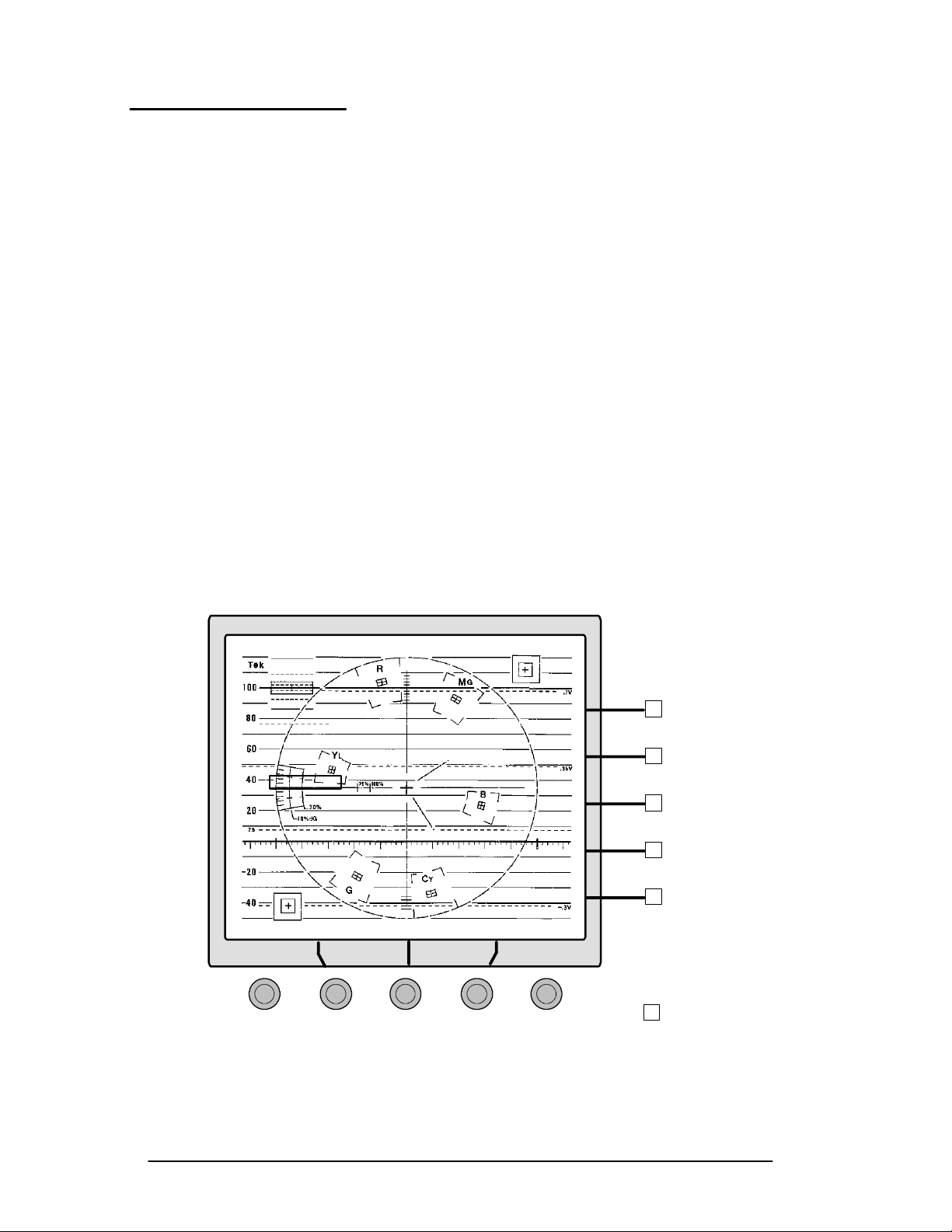
Using the Menus
Preset Menu
The 1740A/1750A--Series has 10 presets capable of storing
front-panel setups. Nine of the presets are user-programmable and one is factory pre-programmed. The factory
programmed setup is as follows:
ON
WAVEFORM, CH-A, DC REST
, 2LINE SWEEP , REF internal, and menus off.
Factory-programmed setup:
INPUT, DC REST ON,
10 µs SWEEP, REF internal, and menus
WAVEFORM DISPLAY, CH-A
off.
Push the
PRESET menu button to access the on-screen menu,
illustrated in Figure 3-5. Turn the left bezel control to select
PRESET location to be acted on (presets 1--9 are available
the
through the menu). Next, use the b ezel button corresponding
to the desired action (
ER
). When a bezel button is pushed, a box flashes momen-
RECALL, STORE, RENAME,orRECOV-
tarily around the on-screen label t o verify tha t the sel ection
has been made.
RECALL
STORE
PRESET 1
PRESET 2
PRESET 3
PRESET 4
PRESET 5
PRESET 6
PRESET 7
PRESET 8
PRESET 9
FACTORY
VERTPOS
Left Center Right
Figure 3-5. The PRESET menu display.
3-16
1740A/1750A Series Waveform/Vector Monitor User Manual
RENAME
RECOVER
HORIZPOS
Bezel
Buttons
CLEAR
MENU
Page 81

Using the Menus
Recall
Use the left bezel control to select (outline) a preset for recall. Push
RECALL to recall the stored instrument configura-
tion.
Recover
RECOVER to restore the front-panel setup that was in
Push
effect before
RECALL was pushed.
Store
To begin storing a setup, push
STORE. Make sure the front-
panel controls are set as desired, and use the left bezel control to select the storage location (shown outlined).
STORE IT to store t he c urrent front-panel setti ngs at the
Push
outlined
sponding to
cel and exit the
PRESET location. (Push the bezel button corre-
RETURN if storing is not de sired. This will can-
STORE operation.)
Rename
Selecting
ing the center and right bezel controls to
. Turn the center control to select the letter that will be
TER
RENAME will provide an on-screen display, assign-
LOCATION and LET -
changed (move the box to the desired location within the
preset name). Turn the right control until the selected letter
changes to the desired new letter.
RETURN if renaming is not desired. All changes to the
Push
name will be cancelled.
When the change has been made satisfactorily, select
CEPT
1740A/1750A Series Waveform/Vector Monitor User Manual
to store the new name.
AC-
3-17
Page 82

Using the Menus
Configure Menu
Push the CONFIG button to display the configure menu,
shown in Figure 3-6. Turn the left bez el control to select
NPUT, VECTOR, FORMAT, STANDARD, OFFSET , CALIBRATE,
I
REMOTE,orREFERENCE (a box appears around the selec-
tion). Following are descriptions of each selection.
INPUT
H COUPLING — Selects AC or DC coupling for
H
H
rear-panel inputs.
DC RESTORER — Selects the clamp speed. Slow
will clamp while displaying any hum.
CLAMP — Selects the point of the video signal that
is clamped to 0. Can be set for
ST (sync tip) or BP
(back porch).
H
A123 — and B123 — When COMPOSITE is se-
lected, the instrument’s internal reference is the
input channel currently selected for display. For
COMPONENT, the internal reference is A1 when A123
is selected, and B1 when B123 is selected (sync is
present only on the first channel).
VECTOR
H BARS — The instrument can be configured to accept
75% or 100% amplitude color bar signals. Dual-
Standard instruments allow color bar signal amplitudes to be set for NTSC and for PAL operation.
H
SETUP — (NTSC operation only) Configures the
instrument to accept signals with or without setup.
H
PAL — (PAL operation only) When +V is chosen,
the phase reference of the --V lines is inverted, then
shown as an overlay on the +V lines to provide a
comparison display. +V shows +V and --V on
alternate lines.
3-18
H
TEST — Used by service personnel; refer to the
service manual.
1740A/1750A Series Waveform/Vector Monitor User Manual
Page 83
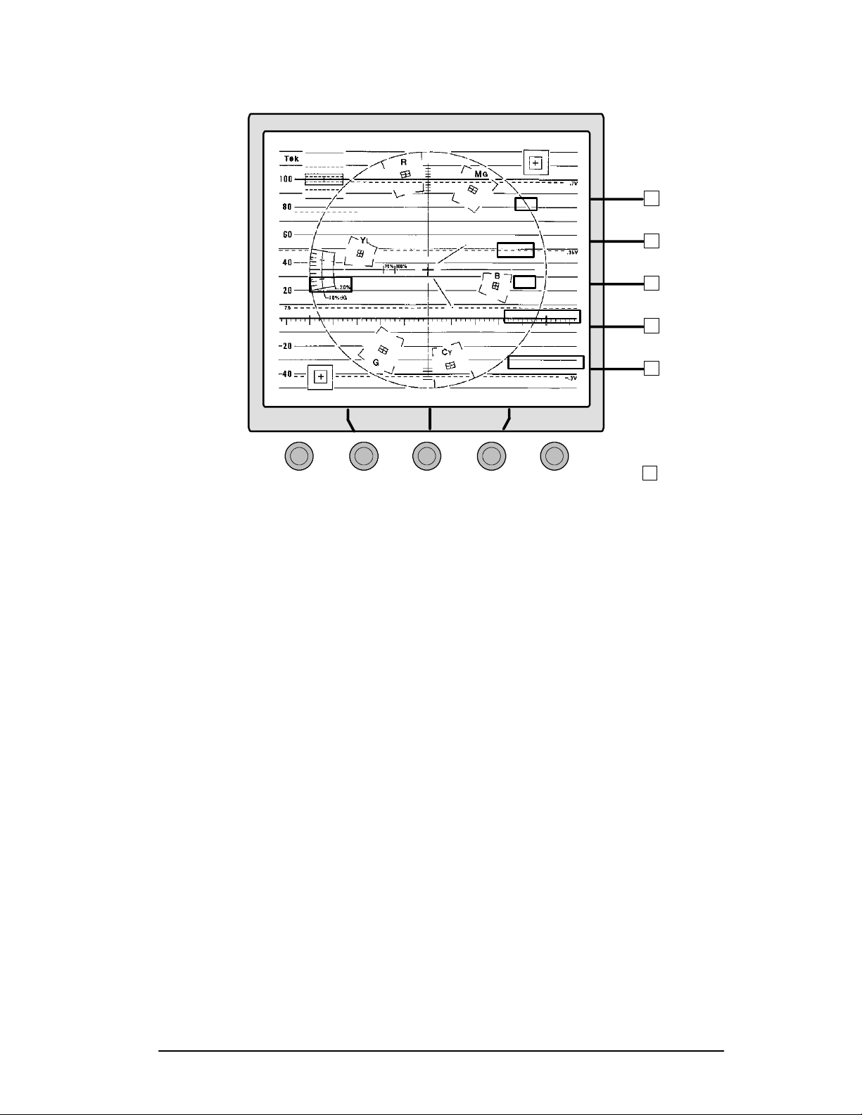
INPUT
VECTOR
FORMAT
STANDARD
OFFSET
CALIBRATE
REMOTE
REFERENCE
COUPLING
AC DC
DCRESTORER
SLOW FAST
CLAMP
ST BP
A123
COMPOSITE
COMPONENT
B123
COMPOSITE
COMPONENT
Using the Menus
Bezel
Buttons
VERTPOS
HORIZPOS
Left Center Right
Figure 3-6. The CONFIGURE menu display with INPUT selected.
FORMAT
H CONFIG—FORMAT is used to to select the configura-
tion of signals used for interconnection of equip-
ment. Available signal formats are:
SMPTE/EBU, BETA, and MII. When viewed as a
waveform parade display, GBR signals can be
displayed in either GBR sequence or RGB sequence,
as selected through the GBR PARADE GBR/RGB
menu. Table 3-1 shows valid forma t selections.
CONFIG—FORMAT is also used to select LIGHTNING
H
or DIAMOND. The present selection will be dis-
played when the front-panel
pressed.
LIGHTNING button is
CLEAR
MENU
GBR,
1740A/1750A Series Waveform/Vector Monitor User Manual
3-19
Page 84
Using the Menus
Ta b l e 3 - 1 . V alid FORMAT selections.
FORMAT
525/60
GBR
SMPTE / EBU
BETA
MII
625/50
GBR
SMPTE / EBU
BETA
[3]
MII
[1]
75% or 100% Bars selected through CONFIG—VECTOR menu.
[2]
Setup Yes or No is selected through the CONFIG—VECTOR
menu. The setup selection is only relevant with 525/60 BETA,
and is ignored in all other formats.
[3]
MII is identical to SMPTE/EBU in 625/50.
BARS
75% 100%
••
••
••
••
75% 100%
••
••
••
••
[1]
SETUP
YN
•
•
•
•
•
YN
•
•
•
•
[2]
STANDARD
H CONFIG—STANDARD allows the user to set the cursor
unit of measure to MV, IRE, or AUTO. When AUTO is
selected, cursor units are automatically changed to
IRE when operating in the NTSC standard, and MV
when operating in the PAL standard.
H For dual-standard instruments, a menu selection of
NTSC, PAL, or AUTO standard is also available.
When
changes automatically to match the standard of the
displayed input signal. A circled “A” precedes
NTSC or PAL on the readout.
AUTO is selected, the operating standard is
3-20
1740A/1750A Series Waveform/Vector Monitor User Manual
Page 85

Using the Menus
OFFSET
H The VERTICAL POSITION control normally positions
all channels together. When
bezel controls can be used to offset input channels 2
A or B)and3(A or B) with respect to channel 1 (A
(
or B).
OFFSET is enabled, the
H While the offsets are enabled, the
control will still position all channels together,
TION
VERTICAL POSI-
with the offset amount remaining constant. When
OFFSET is turned off, the input channels will be
re-aligned. The selected offset amount will be
recalled the next time
H When
A2A3 OFFSET is on, the center and right bezel
controls are assigned to
OFFSET is enabled.
CH A2 and CH A3 offsets.
On-screen labels appear just above each control.
Turning these controls will offset the
signals with respect to CH A1. When B2B3 offset
A3
is on, the same two controls are assigned to
CH A2 and CH
CH B2
and CH B3.
H When both A2A3 and B2B3 offsets are on, the user
assigns the controls to either
CONTROL selection only appears when both A and B
OFFSETS
are selected.
A or B offsets. The
H An offset will remain in effect until the user turns
the offset
affect the
OFF. (Exiting the CONFIG menu will not
OFFSET ON / OFF setting.)
CALIBRATE
These choices are offered when CALIBRATE is selected:
CAL SIG — Turns the 1 V internal calibrator signal
H
on/off.
GAIN CAL — Turns on the gain calibration adjust-
H
ment on/off.
1740A/1750A Series Waveform/Vector Monitor User Manual
3-21
Page 86

Using the Menus
Additional choices appear when CAL SIG or GAIN CAL is
turned on:
CAL SIG
ON
H In waveform mode, the user can set the calibrator
frequency to
3.58 MHz for NTSC/4.43 MHz for PAL).
100 KHZ or to FSC OSC ( FSC OSC =
Dual-stan-
dard monitors also have the option of choosing
NTSC FSC (3.58 MHz) or PAL FSC (4.43 MHz).
H In vector mode, the user can set the ca librator
frequency, for dual-standard instruments only, to
NTSC FSC (3.58 MHz) or PAL FSC (4.43 MHz).
H In both waveform and vector modes, selecting NTSC
or PAL FSC temporarily switches the instrument
FSC
to the appropriate video standard. The standard is
restored when changing the selection or when
exiting the
GAIN CAL
ON
CALIBRATE menu.
H In waveform mode, the left bezel control adj usts
instrument vertical gain
(V CAL) and the center bezel
control adjusts instrument horizontal gain (
H CAL).
3-22
Once gain has been adjusted, two reset options
appear on screen. If either of these resets is selected, a box flashes momentarily around the onscreen label to acknowledge th at reset has occurred.
RESET VCAL cancels any vertical gain adjustments
RESET VCALcancels any vertical gain adjust-
and
ments; the instrument returns to the factory calibrated gain settings.
H In vector mode, the center bezel control adjusts the
vector signal gain. Once gain has been adjusted,
RESET VCAL appears on screen. Selecting RESET
VCAL
cancels any vector gain adjustments and
returns the instrument to the factory calibrated gain
settings.
1740A/1750A Series Waveform/Vector Monitor User Manual
Page 87

Using the Menus
REMOTE
H The currently operating software version is dis-
played in the lower right corner of the screen.
H Three menu choices are available.
REM INPUT
configures rear-panel REMOTE connector pin 3 to
accept External Horizontal or Staircase input.
STAIRCASE configures the staircase input for 3-step
(RGB) or 4-step (YRGB) signal.
BAUD configures
the data transmission rate for the rear-panel RS232
connector for 1200, 4800, or 9600 baud.
H The remote input is enabled by a TTL low or switch
to ground. See page B-1.
REFERENCE (Dual Standard Only)
H NTSC external reference and PAL external refer-
ence can be set to
or B3.
H When The front-panel
lights) the instrument uses the rear-panel
input. Dual-standard monitors can be configured for
two external references; one for NTSC and one for
PAL. Any of the input channels can be designated
as a second external reference by selecting that input
channel as the
through this menu.
EXT, A, A1, A2, A3, B, B1, B2,
REF EXT is selected (LED
EXT REF
NTSC EXT REF or PAL EXT REF
H If NTSC and PAL external references are configured
the same, the monitor automatically operates in the
same television standard as the
When NTSC and PAL externa l re ferences are
configured differently, the monitor’s operating
standard is determined by the standard of the displayed video instead of the
EXT REF input. Once the
operating standard is determined, the monitor
immediately switches to the appropriate i nput for
reference timing.
1740A/1750A Series Waveform/Vector Monitor User Manual
EXT REF input.
3-23
Page 88

Using the Menus
Gain Menu
H Any one of three calibrated gain ratios can be selected:
X1, X5, or X10. Va riable gain is also available, indepen-
dent of the other gain settings. When variable gain is on,
the left bezel control adjusts the signal gain.
CRT Menu
H Audio or Time Code gain is set from the
when
AUDIO or TIME CODE display is selected. Gain
GAIN menu
choices are 0 dBu, 4 dBu, 8 dBu, or 12 dBu. Select gain
relative to the system under test.
H When variable gain is turned off, the instrument returns
to the calibrated gain setting. Operator adjustments
made with variable gain will be restored when variable
gain is selected again.
H DISPLAY is used for signal and etched graticule adjust-
ments. When
adjusts the signal focus (
control adjusts the etched graticule illumination
DISPLAY is selected, the left bezel control
FOCUS), the center bezel
(SCALE)
and the right bezel control adjusts the signal intensity
INTENSITY).
(
H READOUT refers to electronic graticules, markers, menu
and measurement readouts. When
READOUT is selected,
a test pattern containing a vertical line and a horizontal
line is displayed. Use the left bezel control
the center bezel control
(HPOS) until the lines cross at
(VPOS) and
the center of the etched graticule. This will compensate
for minor shifting of markers due to drift or external
magnetic fields (particularly if the instrument is moved
after the markers are set).
3-24
The right bezel control adjusts readout intensity
SITY).
Readout intensity will not go below the calibrated
(INTEN-
minimum value when menus are displayed.
H
TRACE adjusts trace rotation
Exiting the menu will return the instrument to normal operation, with the new settings in effect.
1740A/1750A Series Waveform/Vector Monitor User Manual
Page 89

Remote Operation
The 25-pin rear-panel REMOTE connector is a subminiature
D-type connector. It accepts the input for RGB/YRGB stair-
case, external horizontal, remote sync external blanking, time
code, and Left and Right audio. TTL signal or ground closure to designated pins will enable Staircase, External Horizontal, or Remote Sync displays.
When Remote Sync is enabled, the on-screen
out is not present. When Remote Sync or External Horizontal is enabled with timing cursors, “
place of a quantitative readout.
REMOTE connector is configured for Staircase (RGB or
The
YRGB) or External Horizontal input through the
menu, shown on page 3-18.
The user can store and rec all up to e ight front-panel setups
through the remote. Remote connector pin assignments and
an operational description begin on page B-1.
UNCAL” is displayed in
TIME/DIV. read-
CONFIGURE
Using Presets through the Remote
The 1740A/1750A--Series has 10 presets capable of storing
front-panel setups. Presets one through eight are accessible
through the rear-panel
ground closure on one of the
panel setup stored at that preset location.
REMOTE connector. A TTL low or
PRESET pins selects the front-
When
set pins, the current front-panel setup is stored at the selected
preset location.
1740A/1750A Series Waveform/Vector Monitor User Manual 3-25
STORE (pin 25) is grounded along with one of the pre-
Page 90

Remote Operation
3-26
1740A/1750A Series Waveform/Vector Monitor User Manual
Page 91

Making
Measurements
Page 92

Page 93

Basic Measurements
Basic Measurements contains 1740A/1750A--Series graticule
descriptions, followed by specific measurement procedures.
This monitor uses an internal graticule, which combines waveform and vector markings. The internal graticule sca les
are on the same plane as the CRT phosphor, eliminating parallax errors. Graticule illumination can be adjusted through
CRT menu (page 3-24) to provide optimum brightness for
the
viewing or photographing displays.
Waveform Graticule
There are three versions of the waveform graticule, illustrated in Figure 4-1, Figure 4-2, and Figure 4-3:
H NTSC composite video graticule (1740A and 1750A
only)
H CCIR composite graticule (1741A and 1751A only)
H Dual standard graticule (1745A and 1755A only)
Horizontal Scale
The 0 IRE (0.3V) graticule line is divided into 12 major divisions. Each division represents a unit of time determined by
SWEEP and MAG settings. Line sweep rates are as fol-
the
lows:
SWEEP
1 LINE SWEEP
2 LINE SWEEP
In
2 FIELD SWEEP with MAG ON , the entire vertical interval
TIME/DIV
5 µS/D
10 µS/Div
iv
can be viewed.
MAG ON
200 nS/Div
1 µS/Div
1740A/1750A Series Waveform/Vector Monitor User Manual 4-1
Page 94

Basic Measurements
NTSC Vertical Scales
The NTSC graticule is shown in Figure 4-1. The left side of
the graticule is scaled in IRE units and extends from --50 to
+120 IRE in 10 IRE increments. A mV scale has been added
to the right side of the NTSC graticule to facilitate component measurements.
Black level setup is denoted by a dashed line at 7.5 IRE.
There are ± 2IRE and± 4 IRE markings at the center of the
--40 IRE line to assist in measuring sync amplitude. This
scale is designed for use with two line or two field sweep
rates.
The graticules are also marked for K--Factor tolerances and
linear-distortion measurements. These measurements will be
described later in this section.
KFactor
75% White
Level
Setup
Audio
100% White
Level
Baseline
Sync Tip
Figure 4-1. NTSC waveform/vector graticule.
4-2
1740A/1750A Series Waveform/Vector Monitor User Manual
Page 95

Basic Measurements
PAL Vertical Scale
The PAL graticule is shown in Figure 4-2. On the left side of
the PAL graticule is a voltage scale that extends from 0 to
1.2 V. The graticules are also marked for K--Factor tolerances and linear-distortion measurements. These measurements will be described later in this section.
Component signals can be centered on the .35 V line.
KFactor
Audio
100% White
Level
Baseline
Sync Tip
Figure 4-2. PAL waveform/vector graticule.
1740A/1750A Series Waveform/Vector Monitor User Manual
4-3
Page 96
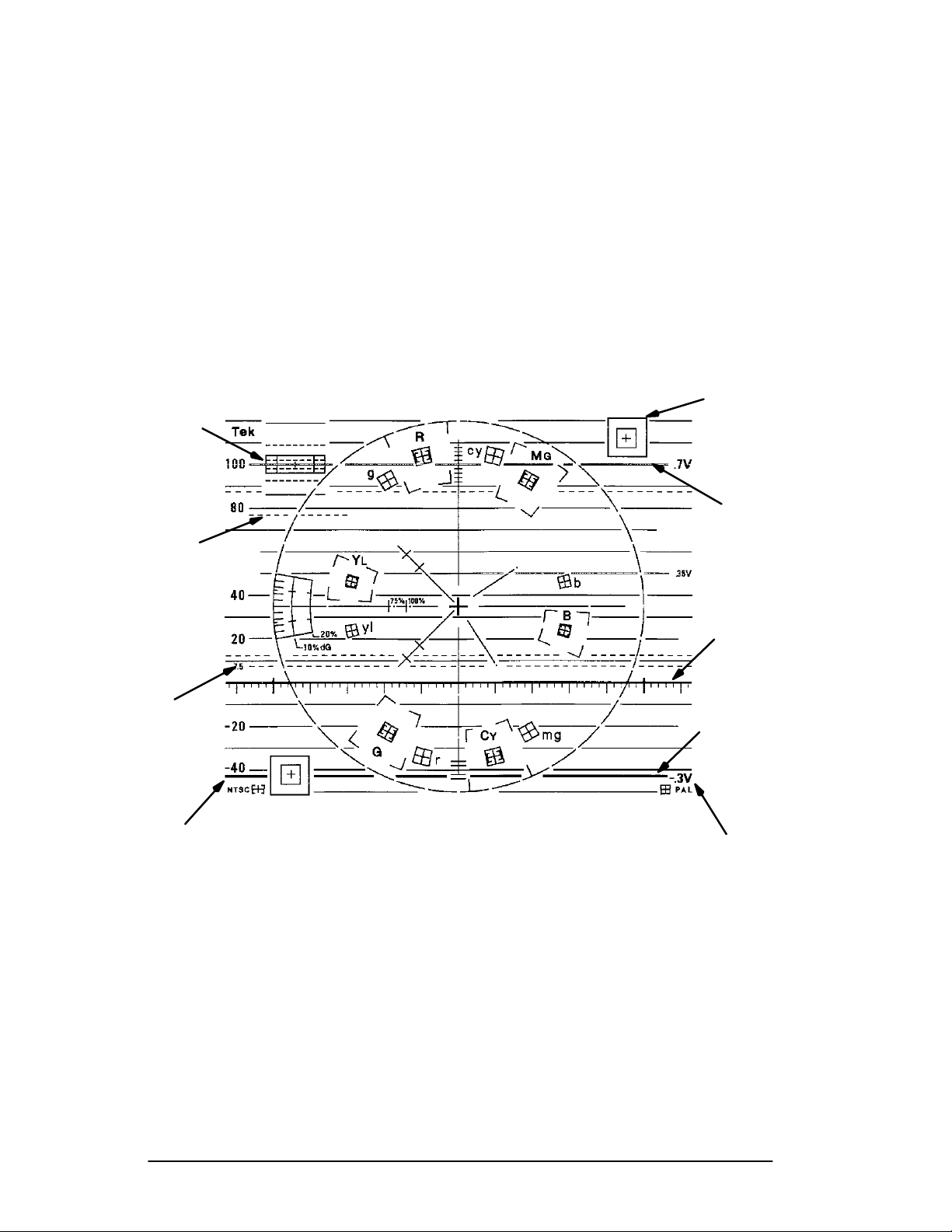
Basic Measurements
Dual-Standard Vertical Scale
The dual-standard graticule combines the NTSC and PAL
scales. The NTSC scale is on the left side; the PAL scale is
on the right. The divisions represent 10 IRE in amplitude (70
mV for PAL). The instrument gain is automatically adjusted
for the particular standard used. On-screen arrows point to
the graticule scale (left side or right side) that is calibrated
for the present operating mode.
KFactor
75% White
Level
Audio
100% White
Level
Setup
NTSC Scale
Figure 4-3. Dual Standard waveform/vector graticule.
Baseline
Sync Tip
PAL Scale
4-4
1740A/1750A Series Waveform/Vector Monitor User Manual
Page 97

Making Waveform Measurements
Horizontal Sync Amplitude
The vertical scale at sync tip (40 IRE NTSC or --0.3 V PAL)
provides ±2and±4IRE(±2and±4 mV) for measuring sync
amplitude. Align the blanking level of a centered two
waveform display on the graticule baseline to place the sync
pulse directly over this structure. Measure sync amplitude
directly from the graticule, or use the voltage cursors.
Peak White
With the blanking signal level on the graticule baseline, the
amplitude of the 100% white reference of a color bar should
be on the 100 IRE (1 V) graticule line. With a
rate, use the
directly over the amplitude scale at graticule center. The
vertical markings there correspond to 2 IRE/division (10 mV/
division for PAL). Measure peak white directly from the
graticule or use the voltage cursors.
HORIZ POS control to place the white reference
Basic Measurements
-line
2LINEsweep
K-Factor Measurements
The boxed area in the upper left corner of the graticule is
scaled for 2% and 4% K--Factor ratings for precise tilt measurements. This structure is designed to work with an 8 µs
half-amplitude duration (HAD) bar. The bar tilt measurement structure can also be used to m easure pulse-to-bar ratio.
Calibrated
X5 GAIN can be used while making these measure-
ments; it increases resolution to 0. 4% and 0.8%.
To use the NTSC vertical scale to make line-time distortion
and pulse-to-bar ratio measurements, position the signal
blanking level to the graticule baseline. Next, position the
center of the composite test signal bar to the center of the 2T
bar measurement box and check to see if insertion gain is
unity. If it is not, adjust the
GAIN MENU) for exactly 100 IRE (700 mV PAL) of signal
VARIABLE GAIN (enabled from the
amplitude from baseline to the middle of the white bar.
1740A/1750A Series Waveform/Vector Monitor User Manual
4-5
Page 98

Basic Measurements
To measure the K-- Factor line-time distortion, measure the
largest deviation of the bar top (tilt or rounding) within the
structure. The solid outer box equals a 4% K--Factor, while
the dashed line inner box equals a 2% K--Factor. For signals
with a bar half-amplitude duration that exceeds 18 s(8s
PAL), measure the bar top in increments by positioning the
bar to the left or right of the leading or trailing edge. The
first and last 1 s of the bar should be disregarded.
Pulse-to-bar K--Factor measurements are made by normalizing bar amplitude (100 IRE or 1V) and adjusting the
POS
structure. Use the
3-24) to adjust signal amplitude.
Make sure that the center of the bar is at 100 IRE (1 Volt
PAL) when blanking level is at 0 IRE (use
adjust gain, if necessary). Use the
place the 2T pulse over the center of the boxed measurement
area and measure its amplitude. When the top of the pulse
falls within the dashed lines, the K--Factor equals 2% or less.
HORIZ
control to position the pulse on the line-time distortion
VAR GAIN (see CONFIG—GAIN menu, page
VARIABLE GAIN to
HORIZ POS control to
4-6
1740A/1750A Series Waveform/Vector Monitor User Manual
Page 99

Vector Graticule
The VECTOR display permits measurements of hue in terms
of the relative phase of the chrominance signal with respect
to the color burst. Relative amplitude of chrominance to
burst is expressed in terms of the displacement from center
(radial dimension of amplitude).
The vector graticule is combined with the waveform graticule.
The NTSC and PAL vector graticules contain burst and vector targets; the dual-standard graticules contain burst and
vector targets for both NTSC and PAL standards. The vector
targets can be used with either 75% or 100% amplitude color
bar signals. The selection is made through the
menu, described on page 3-18.
TOR
Basic Measurements
CONFIG—VEC-
NTSC
The chrominance vectors terminate in a system of graticule
targets consisting of two boxes (a small box inside a large
box). A sample target is shown in Figure 4-4. The dimensions of the large boxes represent ±10° centered on the exact chrominance phase, and ±20% of chrominance
amplitude centered around standard amplitude. The dimensions of the smaller boxes represent ±2.5° and ±2.5 IRE.
1740A/1750A Series Waveform/Vector Monitor User Manual
4-7
Page 100
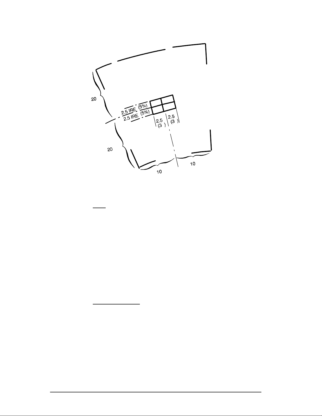
Basic Measurements
°
R
°
°
°
°
°
°
°
Figure 4-4. Vector targets --- NTSC values (PAL values in parentheses).
PAL
For the 1741A and 1751A graticule, each PAL chrominance
vector related to the +V burst terminates in targets consisting
of two boxes (a small box inside a large box). See
Figure 4-4. The large box represents ±10° centeredonthe
exact chrominance phase and ±20% of chrominance amplitude centered around 100% standard amplitude. The dimensions of the inner target show ±3° and ±5% of chrominance
amplitude; the vectors associated with the --V burst terminate
in the smaller targets.
Dual-Standard
The 1745 and 1755 graticule is a composite of the PAL and
NTSC graticules. There are two inner targets within the
larger target; the PAL target, and the NTSC target. The
NTSC target is inside the PAL target.
4-8
1740A/1750A Series Waveform/Vector Monitor User Manual
 Loading...