

Page 1

INSTRUCTION MANUAL
MODEL 168
AUTORANGING DMM
KEITHLEY INSTRUMENTS. INC
Page 2

CONTENTS
‘rifle page
content3
List Of illuarrarions.
Dimensional “ata
Specificarions
1. General Informutio,,
2. Initial Prepururian.
3. operating InSrruCLionS
4. n,eol;y Of operation.
5. MainLenance.
6. Replacevble Partr.
7. Schematic Diagrams
............................
.............................
..........................
I-I. T,“tr”duction
1-2. Warranty Inf”rmation
1-3. Change Notice.
2-1. General.
L-2. Inspfciion
1-3. Preparation for “xe.
3-1. General. ...
1-2. HOW to Select Power.
3-3. HOW f” Make Input Cannccrions.
3-4. ii”W to Select Funcri~o”
1-5. HOW to Measure “olttlge .................
3-6. HUWLOMeaSureCurrent
3-7. How 1” Measure Resistance.
4-1. General.
4-2. halOg circuitry
4-1. DC Voltage Operario”
4-4. nc “oltvge operation
4-5. “HMS OperaLion
4-6. current Operation.
4-7. Power supply
4-8. Digital circuitry.
5-1. General.
5-2. Required Test Equipment.
5-3. Performance “eliflcarlon ................
5-4. AdjusrmentiCalibrarion Procedure ............
5-5. 'rrouhleshooting.
6-1. General.
6-2. Ordering IniormziLion .................. 72
6-3. cross Reference.
6-4. PariS List 74
......................
.........................
......................
......................
........................
.......................
........................
.........................................
.........................
........................
..........................................
........................
......................
..................
.....................
.....................
..................
....................
.......................................
.................
.................
.....................
....................
..................
..................
.....................
...................
....................
.............
...............
................
iii
ii
iv
i
y
I
1
:
2
5
12
;;
1~3
;;
19
26
:;
31
34
16
38
;;
4,
50
50
50
::
;;
71
73
85
Page 3

I
MODEL 168
ILLUSTRATIONS
F
LOClfi”” Of current Fan
M,
ILLUSTRATIONS
Page 4

I
SPBCIFIcATIONS
ml-
MODEL 168
12.75
(324)
iv
DIMENSIONS IN INCHES (MM)
FIGURE 1.
Dimensional m.ta.
:i
0374
Page 5

MODEL 168
SPECIFICATIONS
Page 6

I SPECIFICATl”NS
MODEL
168
FIGURE 2. n-ant Panel
0374
Page 7

MODEL 168 GENERAL INFORMATION
I
SECTION 1.
l-1. INTRODUCTION. The Model 168 is a versatile autoranging digital multimeter useful for meaeurement of ac and dc voltage, ac and dc curre"t.
and resistance.
volts dc or .OOOlvolr to 500 volts ac. current meaSureme"es can be made
from .OOOl milliampere to 1 ampere BC and dc in two spans.
measurements can be made from 0.1 ohm to 20 me&m in two overlapping
spans. Range and polarity is automatically selected. In addition to the
display of digits, the 168 indicates decimal point, function (AC or DC),
and measurement unit (IDA, A, kn, MR).
WARRANTY INFORMATION. The Warranty is give" on the inside front
1-2.
cover of this Instruction Manual.
Warranty, contacf the Keiehley Representative I" your area to de~emine
the proper action co be r&en. Keirhley maintains service facilities in
England, west Germany, as we11 as in the United states. Check the inside
front cover of this Instruction Manual far addresses.
1-3. CHANGE NOTICBS.
occur after printing of the Instruction Manual will be explained on a
Change Notice sheet attached to the inside back cover.
Voltage meaS"remenfs can be made from f.OOO1 volt to t1000
1mprovemenrs or changes to the instrument which
GENERAL INFORMATION
RCS3fSta"CEY
If there is a need to exercise the
I
0374
1
Page 8

‘i
Page 9

,,
CONDENSED OPERATING INSTRUCTIONS
Page 10

(N&M, 11'7)
LINE SWITCHES SET FOR
105 TO 125 VAC OPERATION
4
0374
Page 11

SECTION 2.
2-l. GENERAL. This section provides information needed for incoming inspection and preparation for use.
INITIAL PREPARATION
2-3. PREPARATION FOR "SE.
strument may be powered from line voltage or from rechargeable nickel-cad-
mium batteries (when the optional Model 1688 Rechargeable Battery Set is
installed).
a. HOW to operate From Line Power.
wire line cord which mates with third-wire grounded receptacles. The permanently installed line cord is stored by wrapping the cord around the
base of the instrument aa shown in Figure 4.
1. liow to Set Line Switches. The Model 168 has two rear panel line
switches which are used to select line voltage ranges of 90-llOV, 105125", 195-235", or 210-ZSOV.
,234V (5102) and LOW/NORM (5101).
been defermined, then the line voltage range should be selected from
the four ranges available on the Model 168. For example, when the line
voltage to be used is within the range from 105 fo 125 volts, then ihe
line switches should be set to
voltage to be used is within either of two overlapping ranges, such as
107 volte, then either range may be selected (117V, LOW or 117V, NORM,
for this pareicu1ar example).
anyone of the four ranges are not useable. After the line voltsw
switches are set, connecf rhe line cord and depress the LINE pushbutton
to operate.
Line Fuse Requirements.
2.
co protect the line-operated power supply. The fuse types are l/8
ampere, 3AG slo-blo. Replacement instructions are given in section 5.
The Model 168 is shipped ready-to-use. The in-
The Model 168 provides a three-
The line swirches are idenrified as 117f
Once rhe line voltage to be used has
"117V" and "NORM" ,msitia"s. If the line
Line voltages which are not covered by
The Model 168 requires f"o line fuses
0374
5
Page 12

I
INITIAL
PREPAiUTION
MODEL 168
FIGURE 6. Model 1688 Rechargeable Battery Pack.
0374
Page 13

I
MODEL 168
INITIAL
PREPARATION
b. HOW to operate From Battery Power
Battery set). The Model 168 may be operated from rechargeable nickel-
.A
(Model 1688 Rechargeable
cadmium batteries when ehe optional Model 1688 Rechargeable Battery Set
is installed. The Model 1688 may be field installed at any time or may
be ordered factory installed. The Rechargeable Battery Set includes a
battery pack which mounts within rhe Modal 168. Wiring is accomplished
by a single plug-i" connector. Battery operation from fully-charged
NI-CAD hareeries is eypically 6 hours.
1. How to Install Model 1688 Rechargeable Bateery Set. The bae-
teriea furaiahed with the Model 1688 come already fnstal~led in the
battery pack. The battery pack includes 7 rechargeable "C" cells
(LZV, 2 AMP HR) and 2 rechargeable "button" cella (8.4V, .225 AMP
HR). If batteries need ea be replaced or re-installed, be certain
to observe the proper polarity of individual cells as shown in
Figure 6. TO insrall the Model 1688 Battery Pack, turn the instrument over 80 that the bottom co"er faces up.
BCT~WB on the bottom cover as shown in Figure 4.
Remove four slotted
(A chisel-blade
screwdriver is required to loosen the sloteed screws.) Turn o"er
the instrument with COP co"er facing up, taking,care to hold the top
and bottom covers together. Remove the top co"er to gain access to
the printed circuit board. Check to see ebat the four insulating
standoffs are in position on the printed circuit board. Place the
Model 1688 Battery Pack in position an the standoffs with the cable
oriented 88 shown in Figure 8.
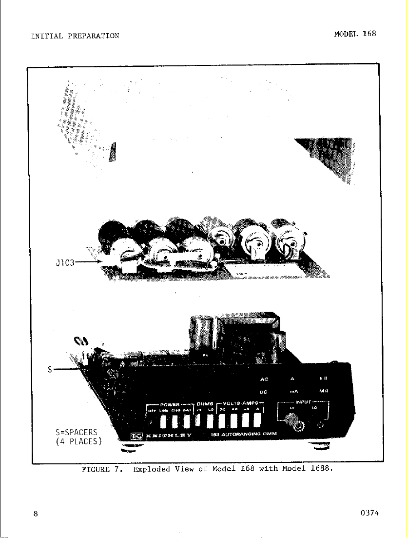
Plug the 4-wire connector (5103) into the mating receptacle 0'103) taking care to oriene the connector
as shown in Figure 8. After the Battery Pack is inscalled, replace
the top cover. Turn o"er the instrument with bottom cover facing up
and inscall the four slatted-head screws.
TABLE 2-l.
Summary of Batteries Used in Model 1688.
0374
Rechargeable "C" cell,
1.2”. 4 Am-km
Rechargeable "Button" type
battery, 8.4V, .225 AMPHR (4 individual 1.2V
Cells)
Quanticv Keithley Part No.
I I
7
2
BA-30
BA-29
7
Page 14
I
INITIAL PREPAR4TION
MODEL 168
s
h
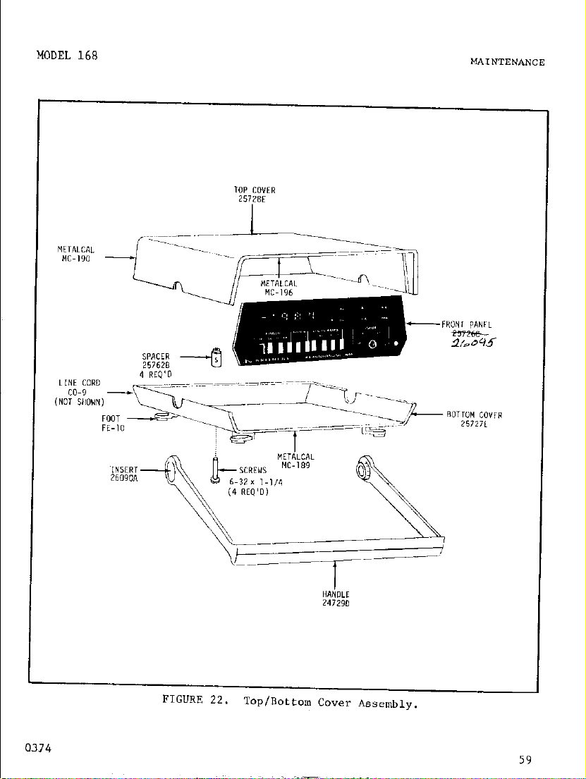
FICUKE 7.
Exploded View of Model 168 with Model 1688.
0374
Page 15

MODEL 168
INITIAL PREPARATION
MODEL 1688 BATTERY PACK
0374
MODEL 168 -".--_-
9
Page 16

INITIAL PREPARATION
MODEL 168
10
FIGURE 9.
Bath-~ ‘feet ~ocatian.
0374
Page 17

I
MODEL 168
2. How to Check Batteries. (Valid only in BAT mode). The Model 168
provides two fest points (A and 8) located on the bottom of the instrument as shown in Figure 9.
of the condition of the internal Battery Pack without need to remove
the Model 168 cover.
ured using the Model 168 or any other comparable voltage measuring
instrument.
BAT mode, connect rhe HI terminal of the Model 168 (for a self check)
or oeher voltmeter to fest points A or B and observe the measured voltage. (If a separate voltmeter is used, it is necessary to make a connection to the LO terminal of the Model 168 since both points A and B
are to be referenced to circuit low.)
voltages required at each teat point.
The instrument mutt be operated in the BAT made in order to obtain
a valid battery condition at test points A and B.
that the batteries are supplying power to the instrument.
voltages are measured when the Model 168 is operated in the LINE
made a different reading may be observed since the batteries are
not connected and therefore do not supply power to the instrument.
To check the voltages at test points A or B, select the
These test points permit a convenient check
The voltage at test points A or B may be meas-
Table 2-2 gives the battery
INITIAL PREPARATION
This will ensure
If the
Summary of Battery Voltage Levels (BAT mode)
Test Point Acceprable Battery Levels Recharge
A 2.9 - 9" 4.8V 2.w B&29
B
3. HOW fo Charge Batteries. The Model 168 provides built-i" recharging circuitry for recharging the Model 1688 Battery Pack. To recharge the internal batteries, connect the Model 168 to line power and
depress the CHG pushbutton. Recharging time is dependent on the condition of the batteries at the time of recharge. Typically, the recharge
time is l-112 hours per bow of discharge (or 9 hours of charging time
for every 6 hours of operating time in the battery mode).
The Model 168 may be operated while in the CHG mode. However,
if the Battery Pack is not installed, the Model 168 will not be
operable when the CHG mode is selected since the batteries are
connected in series with the line power supply.
0374
&+*g,e
7v - 10.5" 8.4V 7v
TABLE 2-2.
Batteries
Normal if below Tested _
RA-30
NOTE
-
11
Page 18

OPERATING INSTR”CTIONS
'MODEL 168
SECTION 3.
GENERAL.
3-l.
Model 168 for measurmene of voltage, current, and resistance.
3-2. HOW TO SELECT POWER.
or rechargeable nickel-cadmium bafteries (when the Model 1688 is installed).
The Model 168 has a built-in line-voltage power supply and line cord. If
the accessory Model 1688 rechargeable Battery Set is ordered and installed,
then Lhe user has the option of selecting line or battery operation via the
front panel pusbbuteons labeled LINE and BAT.
The accessory Model 1688 Rechargeable Battery Set my be ordered at
the fime of purchase of the Model 168 or may be purchased and field
installed at a later time if so desired.
plug-in wiring.
the Model 168 chassis.
a. HO” to operate From Line Power.
ranges of line voltage from a minimum of 90 volts to a maximum of 250 volts,
ms, 50-60 Hz.
ZlO-25OV.
sear Panel
Line S"fGxhf?S 90-110 105-125
This section provides infarmation needed to operate the
me line voltage ranges are 90-llov, 105-125V, 195-235V, and
summary of Line Voltage Switch settinga
OPERATING INSTRUCTIONS
The Model 168 may be powered from line voltage
NOTE
The Model 1688 features
As a result, no modifications need to be made to
The Model 168 is operable over four
TABLE 3-l.
Line Voltage Ranges - Volts, nns, 50-60Hz
195-235 210-250
117/234V Switch (5102)
LOW/NORM Switch (SlOl) LOW
b. HO" to operate From Battery Power. The Model 168 my be used with
the optional accessory Model 1688 Rechargeable Battery Set to provide
portable operation in addition to line operation.
power, depress the BAT pushbutton. Check the battery vaJtage at test
points A and B co ensure that barreries are charged sufficiently.
12 0374
117 117 234
NORM LO"
To operate from battery
234
NORM
Page 19

MODEL 168
Refer to Section 2-3b for instructions concerning installation of the Bat-
eery Pack, battery voltage checks, and recharging.
fully charged NI-CAD batteries is 6 hours minimum. No fuses are required
for operaeion in battery mode.
OPERATING INSTRUCTIONS
Battery operation from
Summary of flattery Voltage Levels (BAT mode)
Test Point Acceptable Battery Levels Recharge Bdtteries
A
8
Summary of Operation in LINE, CHG, and BAT Modes.
PUShbUttOn Line connected
Depressed
OFF
LINE ON
CHG OFF
BAT OFF
The insfrument will be turned off if all power pushbuttons are
released (all non-depressed). A lock-out feature prohibits
selection of two or more puehbuttons at the same time.
3-3. HOW TO MAKE INPUT CONNECTIONS. The Model 168 has two front panel
terminals identified aa “HI” (red) and “LO” (black). These terminals
accomodate banana plugs, alligator clips, spade lugs, bare wires, and
other similar input connections. Leads may be fabricated using a good
quality copper wire terminated by single banana plugs such as Keithley
Part No. 80-S or dual banana plug such as Keitbley Part No. W-7.
Rraay-made tese lead8 are also available from Keifhley. accessory Model
1681 Clip-on Test Lead Set includes two 40 inch long leads terminated by
a banana plug and spring-loaded clip which easily attaches to wires and
terminals on pc boards, etc.
interchangeable probe tips for various applications. The Kit includes
regular probes, alligator clipe, banana plugs. spade lugs, and phone tips.
1688 not installed 1688 installed
RtS”,P$
2.5V - 9V 4.m 2.5V M-29
7v - 10.5v 8.4”
OFF OFF OFF
TABLE 3-2.
Normal
TABLE 3-3.
Condition of Inserument:
Line connected Line not-connected
ON
ON OFF
ON ON
NOTE
Model 1683 Universal Test Lead Kit features
if below Tested
7V
1680 installed
b-30
OFF
0374
13
Page 20

OPERATING INSTR”CTIONS
MODEL 168
14
0374
Page 21

3-4. HOW TO SELECT FUNCTION. The front panel pushbuttons are arranged
to permit selection of five functions including DC voltage, AC voltage,
DC curcent, AC current, and resistance.
a. DC Voltage. To select DC voltage operation, depress the “DC”
pushbutton. Voltage function is implied by the “DC” function indicator.
b. AC Voltage. To aelect AC voltage operation, depress the “AC” push-
button. Voltage function is implied by the “AC” function indicator.
C. DC current. To select DC current operation, depress the “DC” push-
button.
sired range. The %A” and “A” pushbuttons are “push-push” type with lock-out,
such that one pushbutton muet he released before the other can be selected.
d. AC Current. To select AC current operation, depress the “AC” push-
button.
desired currenf range. The “mA” and ‘A” pushbuetons are “push-push”
type with lock-out, such that one pushbutton must be releaeed before the
other can be selected.
e. Re8iStance.
“LO OHMS” or “HI OHMS” pushbutton depending an the desired resistance
range. Either “kR” or “Mn” are displayed depending on range.
DC Voltage
DC Milliamperes
DC Amperes
AC “oltage x
AC Milliamperes x
AC Amperes x
Then select either the “ti” or “A” pushbutton depending on the de-
Then select either the “mA” or
To select resistance operation, depress either the
If all function pushbuttons are released, the inpue to the Model
168 will be disconnected. A lock-out feature prohibits selection
of inconsistent funcrlon pushburtons at the same time.
TABLE 3-4.
Pushbuttons Depressed
DC AC
x
x x
x
Function
Des lred
Summary of Function Settings
Voltage & Current
‘A” pushbutton depending on the
NOTE
CUrrent
d A
x
x
x
Resistance
LO OHMS
“I OHM
Resistance (LO)
Resistance (HI)
x
x
Page 22

OPERATING INSTRUCTIONS MODEL 168
3-5. HOW TO MEASURE VOLTAGE. The Model 168 measures ac and dc voltage
in five ranges: O.lV, lv, IO”, IOOV, and IOOOV dc orlOOOVac (both ac
and dc volts have a maximum inpur of 1200 volts peak ac + dc). The
displayed voltage is direct-reading with decimal point located autonlatica11y.
a. DC Voltage.
f.OOO1 valts dc to $999 voles dc. Above 999 volts, the display reads
properly and flashes to indicate an overrange condition.
at the HI eerminal is negative,
minus sign.
lighted “DC” and decimal point are also displayed for all dc measurements.
1. How to Measure DC Voltage. Select the dc function by depressing
the “DC” pushbutton.
I.0 terminals. Observe the displayed digits, polarity sign, and decimal
point lacacion. The lighted “DC” indicates that the dc voltage function has been selected.
2. How to Select Range. The Model 168 autamaeically selects the
appropriare range for all valtage measurements.
3. How to Determin+ Accuracy.
reading ~1 digit.
will have an uncertainry of ~0.1% 51 digit or +.002 volts. The input
resistance in rhe dc mode is 10 megohms. Measurements from relatively
high source resistances could cause an additional reading error. The
amount of error due to loading can be determined by ehe following
relatianship:
For example, a scurce resistance of 10,000 ohms will result in a
loading error of approximaeely 0.1% of reading.
4. How fca Determine Maximum Allowable Input. The maximum allowable
voltage input is 1200 volts dc + peak ac. The Model 168 displays dc
voltages to i999 volts. Beyond 999 volts fhe display reads properly
and blinks to indicafe an overrange condition.
The Model 168 automatically displays voltage from
If the polarity
the Model 168 display indicates a (-)
If the minus sign is off, a positive voltage is implied. A
Connect the signal to be measured between I+1 and
The Model 168 accuracy is ~0.1% of
For example, a display reading of 1.000 volts dc
% error = 100 x Ks i (Es i 107)
where R, = source resistance in ohms.
IMPORTANT
The Model 168 provides ac rejection of greater than 75 dB (NMRx).
However, a large ac signal superimposed on a dc level could case
damage if the inpue exceeds 1200 volts dc + peak ac.
16
0374
Page 23

/
MODEL 168
“PERATINC TNSTRUCTTONS
5. HOW to ZerO the Display. The Model 168 has a front panel zero adjuscment which may he used to zero the display to compensate for zero
offset. Apply a &xc connection bctwee” the input terminals or select
“A” function and adjust the zero control (screwdriver required) to obtain a .OOOO display with the minus (-) polarity flashing on and off.
b. AC Voltage. The Model
168 automatically
displays voltage fror .OOO1
volts ‘co 499 volts ac rms. Above 499 volts, the display reads properly
and flashes to indicate an overrange condition. In the ac function, the
Model
168 operates as an
average-reading voltmeter, calibrated in terms of
the root-mean-square (rms) of a sine wave. ‘The ac-to-dc converter is a fullwa”e rectifier type, and as such the calibration is exact for sinusoidal
waveforms.
lifier so that dc is blocked.
The input signal is ac coupled (capacitive) to the input amp-
me 1np”t bLocking capacitor effectively
reduces the Model 168 low-frequency response to approximately 20 HZ.
1. HOW to Measure AC Voltage.
Select the ac function by depressing
the “AC” pushbutton. Connect the signal to be measured between HI and
LO terminals.
Observe the displayed digits, and decimal point location.
The lighted “AC” indicates chat the ac voltage function has been selected.
2. mw to se1ecr Range.
‘The Model 168 auramarically selects tire
appropriate range for a volksge Ineas”reme”t.
3. How to Determine Accuracy.
The Model 168 accuracy is 1(0.5X of
reading ?0.3% of range). For example, a display reading of 1.000 volts
ac “ill have an uncertainty L.008 volts over a frequency range from
20 HZ to 10kHz. An additional reading error may result if the source
resistance is relatively high.
is frequency dependent.
For example, with an input resistance of 9
The input impedance of the Model 168
megohms and shunt capacitange of less than 90 picofarads, the effoc-
tive input impedance at 60 HZ is approximately 8.23 megohms. The impedance at other frequencies may be determined by the following relationship.
Zin =
Rin
1 + (2nf R&)Z
I
0374
where 2.1~ = effective input impedance
R
sin < 90
in =
9 x
lob
ohms
x lo-6 farads
= frequency in HZ
17
Page 24

MODEL 168
Source loading can be determined by the following relationship:
% error = 100 x z,
% + Zi”
4. How to Determine Maximum Allowable Injxt. The maximum allowable
voltage input is 1200 volts dc + ac peak. The Model 168 displays ac
voltages to 499 volts rms.
Beyond 499 “olfs the display reads properly
and blinks to indicare an overrange condifion.
NOTE
The Model 168 blocks dc signals at the input as a result of the
capacitive coupled input. Howe”er, a large dc si@,al superimposed
on an ac level could cause damage if the inpuf exceeds 1200 “olcs
dc + peak ac.
C. “oltaae Measurements using Model
1682. The Model
168 may be
used
with the accessory Model 1682 RF Probe to permit ac voltage measurements
from 100 kHz to 100 EMz. The transfer accuracy of the 1682 is t5%, cal-
ibrated in rms of a sine wave.
Input impedance is 4 megohms shunted by
2pF. Maximum allowable input is 30” rms AC, 200” DC. To use the 1682
with rhe Model 168, connect the probe to HI and LO. Select DC voltage
function. Voltage is direct reading in “olts ac rrxs.
The Model 1682 is designed for use with a voltmeter having an
input resistance of 10 megohms ilO%.
I
18
0374
Page 25

MODEL 168
OPERATING INSTR"CTIONS
3-6. HO" TO MEASURE CURRENT. The Model 168 me=="ree ac and dc current
in four ranges; O.lmA, ImA, O.lA, and 1A.
The displayed current is direct
reading in terms of milliamperes ("!A) or amperes (A) (depending on mode
selected) with decimal point located ="tam=tic=lly.
DC current.
a.
The Model 168 me=="ree dc current from .OOOl mA to 2 mA
end frbm .OOOlA to 1A. If the Polarity at the "I terminal is negative,
the Model 168 display indicate= a (-) minus sign. If the minus sign is
off, a positive current is implied. A lighted "DC" is displayed when the
dc function is selected. Current may be selected for direct reading in
terme of milliamperes (mA) or amperes
current measured.
When the ampere=
(A)
depending on the magnitude of
(A)
mode is selected, ehe Model 168
measures current from 0.0001 ampere to 1 ampere. (The display will Permit a reading up to 1.999 amperes or until the 2A fuse blows.) When the
milliampere (mA) mode is selected,
0.001 milli=mpere to 2 mi11*=nlperes.
the Model 168 measures current from
(The display will permit a reed-
ing up to 9.99 IDA or until the lOmA fuse blows.)
1. How to Measure DC Current.
the "DC Pushbutton.
First select "A" mode.
Select the dc function by depressing
The "mA" and "A" pushbuteona
are "push-push" type, such that one pushbutton m"se be released before
the other can be selected.
terminals.
Observe the displayed reading,
tive inputs), and decimal point position.
that the dc function ha= bee" selected.
Connect the input signal between HI and LO
the polarity sign (for negaThe lighted "DC" indicates
The lighted ",,!A" or "A" indi-
cates that the current mode has been selected.
2. HO" to Select Ranges.
sensitivity for either %A" or
is between 0.0001 mA and 2 mA, select the %A" mode.
The Model 168 automatically defermine= the
“A”
modes.
If the current to be measured
If the current to
be measured is between 0.0001 A and lA, select the "A" mode. For either
%A" or "A" modes, the Model 168 has two sensitivities, 0.1000 and 1.000
full range.
while the maximum reading ie .1999.
On the most sensitive range, the minimum reading is .OOOO
When the input exceeds .1999, the
Model 168 a"tom=tically "p-ranges to the higher range and decimal Point
location is changed appropriately.
Down-ranging occurs when the input
level is reduced, causing a dieplayed reading to be less than 1-9-O on
any range.
0.189, the display will change from .190 to .1890.
For example, if =n input signal is reduced from 0.190 to
However, if the sig-
nal is increased from .1899 to .1900, the Model 168 will not "prange,
but remain on the 0.1000 range.
0374
19
Page 26

OPmATING 1NSTR”CTIONS
FRONT PANEL
MODEL 168
CURRENT RANGE FUSES
20
FIGURE 11. Locafion of
Current Range Fuses.
0374
Page 27

3. HOW to Determine Accuracy.
of reading + 0.1% of range).
have an uncertainty of +.004 ampere.
uses a 1000 ohm shunt resistor.
The accuracy of the Model lb8 is t(O.3%
For example, a display of 1.000 ampere will
I" rhe ?,,A" mode, the Model 168
In the "A" mode, the Model 168 uses a
1 ohm shunt resistor. An additional reading error shauid be considered
if the so"rce resistance is not greater then 1000 times the shunt re-
sistor. For example, in the "mA" mode,
a source resistance of 100 kilohm would result in a loading error of approximately 0.1% of reading.
Loading error for other eource resistances can be determined by the
following relationship:
% error - 100 X R, (mA mode)
R, + 1000
where R, = eource resistance
or % error =loo X %( A mode)
R
6
4. Ho" to Determine Maximum Allowable Input. The Model 168 uses
separate fuses for each current mode.
a 10 milliampere fuse.
The "A" function ie protected by a 2 ampere
The ?,,A" mode ie protected by
fuse.
a) HOW to Check the Current Range Fusee.
To determine the condition of fuses for "IDA" and "A" modes, select the "Lo OHMS" resistance mode. Since the shunt resistors are connected between HI end
LO terminals, the resistance including fuse can be meaeured directly
an the Model 168.
observe the display.
kn to indicate a "good fuse".
fuse.
display.
For the "A" mode, select the "A" pushbutton and observe the
The display should read approximaeely .0012 kn to indicate
For rhe "mA" mode, select the ?,,A" pushbutton end
The display should reed approximately 1.180
A flashing display indicates a "blown"
a "good" fuse. A flashing display indicates a "blown" fuse.
b) How to Replace the Current Range Fuaee. The current range fuses
F103 and F104 are located on the printed circuit board. The fuses are
accessible by removing the fop cover and internal shield. TO replace
the fuses, turn the instrument over 80 that the bottom cover faces up.
Use a screwdriver to remove the four slotted screwe on the bottom
cover as shown in Figure 4. After the ecre"s ere removed taking cere
CO hold the top and bottom covers together, turn o"er the inetrumen~
so that the top cover faces up. Remove the top cover to gain access
to rhe printed circuit board. If the Model 1688 Rechargeable Battery
Page 28

OPeRATING INSTRUCTIONS
MODEL 168
Pack is installed, lift off the battery pack from the stand-offs cod
set to the left of the instrument.
The fuses for current ranges are
located on the prineed circuit board near ehe front right side under
the shield.
rhe fuses.
a single Phillips head screw.
The amplifier shield must be removed to gain access to
The shield.&? fastened to rhe circuit board by means of
Before the ecrew can be removed, the
front panel most be lifted out of, the way. Gently lift the front
panel and pull forward until panel is clear of puehbuttoos.
and remove the Phillips head screw which holds the shield.
Locate
The metal
shield is held by clips to fhe printed circuit board and must be pried
Replace fuses as necessary.
UP.
FlO3:
O.OlA, 25OV,
type 8AC, fast acting (%A" mode)
Fuse types are as follows:
~104: 2.4, 250", type 8AG, fast acting ("A" mode)
After fuses are replaced, re-assemble shield, spring, washer, ana
Phillips Screw as shown in Figure 11.
Model 1688 battery peck on stand-offs.
Replace front panel. Replace
Replace top cover. Take care
fo hold top and bortom covers together and turn over instrument so
that bottom cover faces up.
Replace Screw to complete re-assembly
of chassis.
b. AC Current.
The Model 168 measures ac c"rrent from .OOOlmA to 2mA
and from .OOOlA to 1A. A lighted "AC" is displayed when the ac function
is selected.
milliamperes (nut) or amperes
Current may be selected for direct reading in cerme of
(A)
depending oo the magnitude of current
?a be measured. When the amperes (A) made is selected, the Model 168
measures currenf from .OOOl ampere to 1 ampere.
(The display will permit
a reading up to 1.999 amperes or until the 2 ampere fuse blows.) When
the milliampere (mA) mode is selected, the Model
from .OOOl milliampere to 2 milliamperes.
168 neasures current
(The display will permit a
reading up to 9.99 mA or until the 10 m.4 fuse bl.ows.)
1. How to Measure AC Current. Select the ac function by depressing
the "AC" pushbutton. First select "A" mode. The "mA" and "A" pushbuttons are "push-push"
before the other can be selected.
type, such that one pushbutton must be released
Connect the input signal between HI
and LO terminals. Observe the display4 reading, and decimal point
position.
selected. The li.ghrcd "ti" or
The lighted "AC" indicates that the ac fuoctioo has been
“A”
indicates that the currant mode has
been selected.
22
0374
Page 29

MODEL 168
ROW to Select Ranges.
2.
sensitivity for either “IDA” or “A” modes.
is between O.OOOlmA and 2mA, select the “m,” mode.
be measured is between O.OOOlA and lA, select the “A” mode. For either
““A” or “A” modes, the Model 168 has two sensitiviries, 0.1000 and 1.000
full range. on the most SenSitiVe range,
while the maximum reading is
Model 168 automatically up-ranges to the higher range and decimal point
location is changed appropriately.
3. How to Determine Accuracy. The accui-acy of the Model 168 is k(l%
of reading + 0.3% of range). For example, a display of 1.000 ampere
will have an uncertainty of t.013 amperes (over a frequency range from
30 RZ to 5lcHz).
sister. An additional reading error should be considered if the source
resistance is not greater than 1000 times the shunt resistor.
in the “ti.” mode, a source resistance of 100 kiloh would result in a
loading error of approximately 0.1% of reading.
source resistances can be determined by the followinS relationship:
In the YnA” mode, the Model 168 uses a 1000 ohm shunr re-
% error = 100 X R, (“,A mode)
The Model 168 automatically determines the
If the current to be measured
the minimum reading is .OOOO
.1999. When the input exceeds .1999, rhe
R, + 1000
OPERATING INSTRUCTIONS
If the current to
For example,
Loading error for other
4. Uaw to Determine Maximum Allowable Input. The Model 168 uses
separate fuses for each current mode. The “mA” mode is protected by
a 10 milliampere fuse.
a) HOW to Check the Current Range Fuses. TO determine the condition of fuses for %A” and “A” modes, select the “LO OHMS” resistance mode.
LO terminals, the resistance including fuse can be measured directly
on the Model 168. For the “mA” mode, select the “,“A” pushbutton and
observe the display.
kQ to indicate a “good. fuse”.
fuse.
display.
a “good” iuse.
0374
Since the shunt resistors are connected between HI and
For the “A” mode, select the “A” pushbutton and observe the
The display should read approximately .0012 kn to indicate
A flashing display indicates a “blown” fuse.
The “A” function is protected by a 2 ampere fuse.
The display should read approximately 1.180
A flashing display indicates a “blown”
23
Page 30
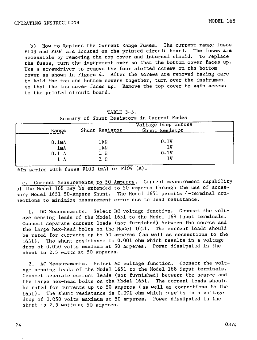
s,,mary of Shunt Resistors in Current Modes
TABLE 3-5.
Voleage Drop zlCTO88
Range
Shunt Resistor
Shunt Resistor
O.hA
1mA lki?
0.1 A
1.4 10
Ikn
In
0.1”
1”
0.1”
1”
*I” series with fuses F103 (“A) or F104 (A).
current Measurements to 50 Amperes.
C.
Current measurement capability
of the Model 168 may be extended to 50 amperes through the “se of accessory Model 1651 50-Ampere Shunt.
The Model 1651 permits 4-terminal co”-
nections co minimize measurement error due to lead resistance.
1. DC Measurements.
Select DC voltage function. Connecf the voltage sensing leads of the Model 1651 to the Model 168 input terminals.
connect separate current leads (not furnished) between the source and
the large hex-head bolts on the Model 1651. The current leads should
be rated for c”rre”ts up to 50 amperes (as well as connections to the
1651).
The shunt resistance is 0.001 ohm which results in a voltage
drop of 0.050 volts maximum at 50 amperes. Power dissipated in the
shunt is 2.5 watts,at 50 amperes.
2. AC Measurements.
select *c voltage function. connect the voltage sensing leads of the Model 1651 to the Model 168 input terminals.
Connect separate current leads (not furnished) between the source and
the large hex-head bolts on the Model 1651. The current leads should
be rated for currents up eo 50 amperes (as well as connections to the
1651). The shunt resistance is 0.001 ohm which results in a voltage
drop of 0.050 volts maximum at 50 amperes. Power dissipated in the
Shunt is 2.5 watts at 50 amperes.
24
0374
Page 31

VOLTAGE TERMlNALS
I \
0374
FIGURE 12.
-\/
current Measurements using Model 1651.
CURRENT TERMINALS
CURRENT LEADS NOT SUPPLIED
25
Page 32

The largest resistance displayed in the 1.0 OHMS mode is 1.999 megohms. Beyond 1.999 megohms, the display flashes co indicate an overrange condition although the reading will be displayed up to 2.017
megohms. Above 2.017 megohms,
ii1 ONbE mode, the maximum reading is 19.99 megohms.
the display will not change.
Beyond 19.99
In the
me&ms, the display flashes to indicate an overrange condition ai,-
though the reading will be dLsplayed up to 20.17 megohms. above
20.17 megohms, rhe display will not change.
26
0374
Page 33

Care should be taken when making resistance measurements in circuits
which may have voltages on capacitors etc. or where line voltage is
present.
al voltages up to 25OV rms in OHMS. if higher voltages are applied
damage may occur.
d. HOW t" Determine Accuracy. The accuracy of the Mr,del 168 is f(O.2%
of reading + 0.1% of range) in HI OHMS. For example, a display reading of
1.000 kilohms will have a" uncertainty of f0.003 kilohma.
e. How to Determine the C"rrene For Each Range. The voltage developed
acro88 the resistance is directly proportional to the current applied.
For instance, a reading of 1.000 kilobms corresponds to a voltage develap-
ed of 0.900 volts in HI OHMS.
termined by dividing the voltage by the resistance being measured.
previous example, the current is equal t" 0.9OOV i 103n - 0.9 mA. The teec
current for each range is given in Tables 3-6 and 3-7.
Although the Model 168 is fully protected against accident-
The ~"rrent applied by the Model 168 is de-
In the
Test Current in LO OHMS Mode
.-
Range
O.lk0
lkfl
lOkR
0.lMn
1m
f.
How to Test Semiconducfor Diodes and Transistors. The Model 168 can
be used to test diodes and transistors t" determine the condition of the
device.
to cause conduction in the forward direction.
Model 168 provides a voltage up t" 2 volts at a current of 1 milliampere,
which is sufficient to cauee conduction.
rive With respect to the "HI" terminal far all resistance measurements,
connections should be made aa eh"wn in Figure 13 t" cause forward conduceion of diodes.
0374
TABLE 3-6.
Test current in HI OHMS Mode
Test Current
0.9*
0.09m.4
0.009m.4
0.9"A
0.09"A
For semiconductor diodes, the voltage applied must be sufficient
Since the "LO" terminal is poai-
TABLE 3-7.
The "HI OHMS" mode of the
27
Page 34

NOTE
me silicon diode test should be performed using the 1o”esC resistance
range of HI OHMS, (2 kilohms maximum reading) since the current used
an the higher ranges becomes small.
when rhe input terminals Of the
Model 168 are open, the instrument automatically ranges to the highest range.
TO perform the diode test,
a short m"Se first be applied
to the input terminal*, causing the Model 168 to downrange to the
lowest range. An easy way to accamplish this measurement is to depress the "A" pushbutton (which "ill callse the Model 168 to downrange to the loweet resistance). men connect the diode and release
the "A" pushbutton. Observe the displayed reading on the Model 168.
A reading less rtmn 1000 ohms (for silicon semiconductors) indicates
that the diode is conducting.
If the diode is faulty or connected
in TeYerse, the display will flash O.lnm which indicates that cLie
resistance is greater than 20.17MR.
The I.0 terminal is positive so
that anode must be connected to LO.
TO determine the semiconductor type (NPN or PNP) of a transiscar, a measurement between base (B) and emirter(E) is required. First, identify the
leads of the transistor by comparing the device to the appropriate tran-
sisror configuration as shown in manufacturer's data sheets.
Nexf, measure the resistance between hasa (9) and emltfer(E). If the tran-
sistor is a,, Nl'N type, the "LO" terminal of the Model 168 should be connected
to the base (B) to cause the base-emitter junction to conduct.
A properly
conducting junction "ill be leas than 1000 ohms for all NPN transistor.
If the transistor is PNP type, the "LO" terminals of the Model 168 should
be connected to the emitter (E) to cause the base-emitter junction to cmduct. A properly conducting junction will be less than 1000 ohms for a
PNP eransistor.
TO determine the condition of a transistor, a measurement
of base-emitter and base-collector junctions is required. Table 3-8 describs the conditions which will determine if an NPN type transisror is
faulty. Table 3-9 describes the conditions which will determine if a PNP
transistor is faulty.
28 0374
Page 35

I
MODEL 168
HI i-)
t
CATHODE
CONDUCTION
LO (+I
t
ANODE
OPERATING TNSTRUCTTONS
LO
+
EMITTER-TO-BASE
CONDUCTION
HI- B
0374
29
Page 36

:onnection
CO LO
Terminal
Connection
TO HI
Terminal
(HI OHMS)
Condirions Which Indicate
A Normal 01 Faulty Transistor.
Base
Emitrer Base
Collector Base
Base
Emitter
Collector A reading of approx. 700 ohms indicates a
Connection
Terminal A Normal or Faulfy Transistor.
Base
Emitter
to "I
A reading of approx. 700 ohms indicates a
normal junction.
1000 ohms indicates a faulty junction.
A reading greater thatI 20.17MR indicates
a normal junction.
20.17Mn indicates a faulty junction.
A reading greater than 20.170 indicates
a normal junction. A reading less than
20.17MR indicates a faulty junction.
normal junction.
1000 ohms indicates a faulfy juncrion.
TABLE 3-9.
Conditions Which Indicate
A reading of approx. 700 ohms indicates a
normal junction. A reading greater than
1000 ohms indicates a faulty junction.
A reading greater than 20.17MCI indicates
a liornml junction. A reading less than
20.17MR indicates a faulty ,unction.
A reading greater than
A reading less than
A reading greater than
(HI OHMS)
Base
Collector
30
ea11ecror
BaSe
A readhg greater than 20.17.W lndica~es
* normal junction.
20.17MO indicates a faulty junction.
A reading of approx. 700 Dhms indicates a
normal junction. A reading greater than
1000 ohms indicates a faulty junction.
A reading less than
0374
Page 37

MODEL 168
THEOKY OF OPEKATION
SECTION 4.
4-1. GENERAL. This section coniains information to describr the Elodci I68
circuit operatim.
a. Class-epoxy printed circuit boards are used for all circuitry.
analog and digital circuitry is located on mother board, PC-346.
ital display circuitry is located on display board, ~~-347.
b. Compactness and high reliability are provided rhrough ~hc ust: of A
digital LSI, a completely solid-state LED displ~ay, thick-film resisror
networks, and linear integrated circuits.
All circuit designations refer to components shown on schematics
26088E and 26089E located on pages 85 and 86.
4-2. ANALOG CIRCUITRY
*. First stage Amplifier. This amplifier is * FET input i"Legratcd
circuit (QA103) connected as an inverting amplifier. Gain for the ml,lifter is set by automatically switching resistors with JFCT'S into the
feedback of the amplifier.
ment on the front panel.
Second Sfage Amplifier. This amplifier provides additional gain f"r
b.
rhe most sensitive ranges. Integrated circuit 4.4104 is connected as an
inverting amplifier with a gain of X1 or X10. Potentiometer R139 (-IV AD.J.)
is a gain adjustment for x10 gain. Potentiometer R115 is a zero adjusfment
for Xl gain. Porentiometer R137 is a zero adluetment for Xl0 gain.
DC Cain Switching (UP-Ranging)
THEORY OF OPERATION
'The
'rile clip,-
Potentiometer R135 is an input zero adjust-
TABLE 4-l.
Iboge
0374
First stage Gain
0.9 10 9.0
0.09 10 0.9
0.009 10 0.09
0.009
0.0009
Second Stage Gain Overall Gain
1
1
0.009
0.0009
31
Page 38

0374
Page 39

I
MODEL 168
THEORY OF OPERnTTON
0374
rlG”Re 15.
Full wave Rectifier.
33
Page 40

100"
10"
I"
0.1"
0.009
0.09
0.09
0.9
0.009
".09
0.9
9
Page 41

MODEL 168
THEORY OF OPERATION
35
Page 42
THEORY OF OPERATION
I
MODEL 168
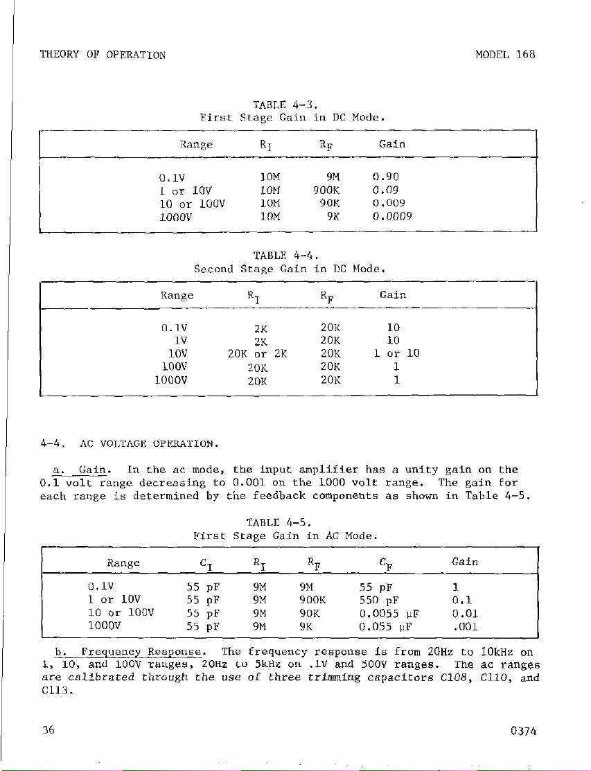
TABLE 4-3.
Range
0.1”
1 ox- IOV IOM 900K 0.09
10 o* 1oov 10M 90K 0.009
1000"
0.1"
1"
1ov 20K or 2K 20K
1oov
1000"
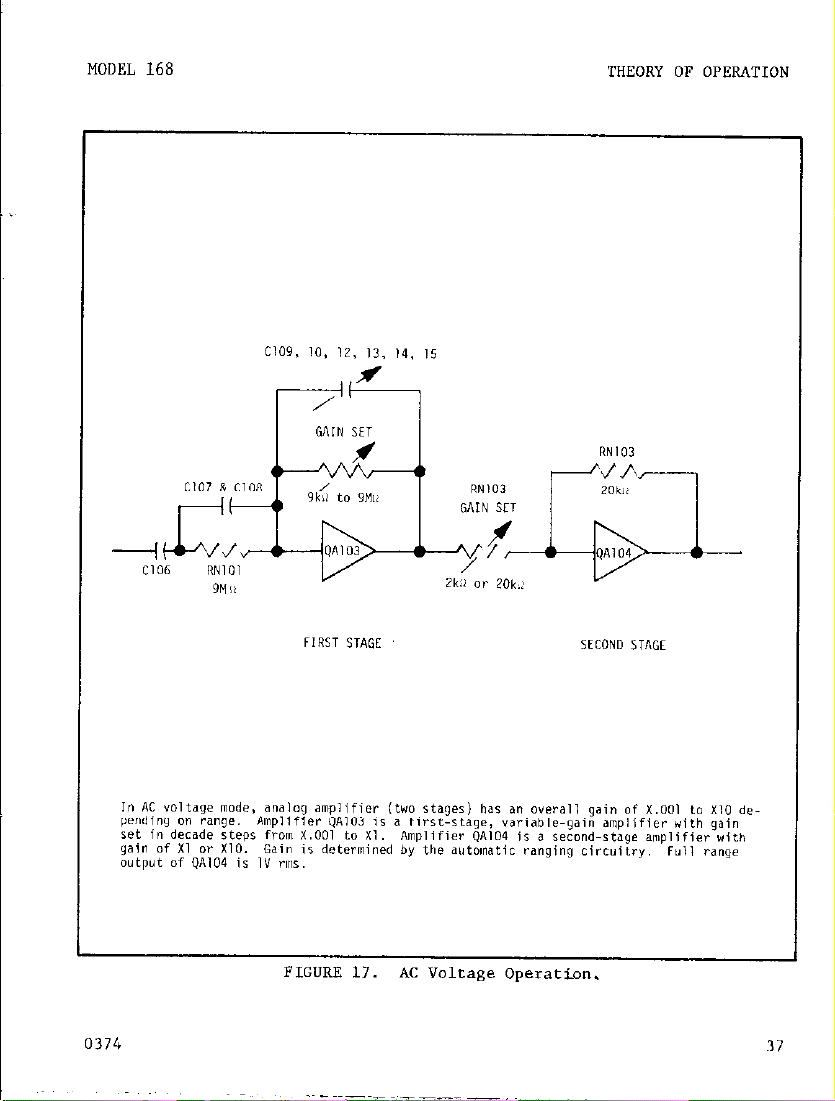
4-4. AC "OLTAG~ OPERATION.
a. Gain.
0.1 volt range decreasing to 0.001 on the 1000 volt range. The gain far
each range is determined by the feedback components as shown in Table 4-5.
In the ac mode, the input amplifier has a unity gain on the
RI RF
10M 9M
10M
ZK
2K
20K
20K
9K
20K
20K 10
20K 1
20K
Gain
0.90
0.0009
10
1 c!r 10
1
0.1”
1 or 10” 55 pF 9M 900K 550 pF 0.1
10 or 100" 55 pF 9M 90K 0.0055 !lF 0.01
1000"
6. Frequency Response. me frequency response is from 20HZ to 1OkHZ on
1, 10, and 100" ranges, 20Hz to 5kHz on .lV and SOOV ranges. The ac ranges
are calibrvted eirraugtl tile use of three trinmling capacitors C108, c110, and
c113.
I
36
55 pF 9M
55 pF
9M 9K 0.055 UF .OOl
9M
55 pF I
0374
Page 43
I
MODEL 168
THEORY OF OPERATION
Page 44

I THEORY OF OPERATION
OHMS OPERATIQN. n, the OHMS mode, the input terminals (“HI” and
4-5.
“LO”) are connected in the feedback of ~~103 so as to reduce the slowing
effects at cable capacitances.
current in decade steps is applied between the input terminals with the
LO terminal posifive.
circuit &WI6 and range resistors RNLOl-1, -4, -5, and -6 which are also
used on voltage modes. An addieianal resistor RIO5 is used on the Ikn
range.
the range resistor.
portional to the measured resistance.
sister is connected, the voltage developed is .81” t 9M x 15M = 1.35V.
PaCentiomeCer El22 is the adfustmenc for the 1OOkR range.
sets the output of QUO6 to approximately -.81 volts.
R109 is the adjustment for the lkn range.
mode only. Maximum open circuit voltage across the terminals ia 6 volts
in series with 9Mfl in eirher HI or LO OHMS.
The test current is generated by the-.81” reference volta’@ and
The OHMS reference is composed of integrated
The voltage developed across the terminals is pro-
When the OHMS mode is selected, constant
For example, when a 15 megohm re-
This control
Potentiomefer
Adjustments made in high ohms
MODEL 168
Test Currenr in HI OHMS Mode
HI OHMS Test
Range current
1 kn 900 “A
10 kR 90 !liA
100 kil
1 Mn
10 Mn 0.09 !A
9 WA
0.9 !lA
Test Current in I.” OHMS Mode
TABLE 4-6.
Ilange Maximum Voltage Developed
Resistance
90K 1.8”
900K 1.8”
Range
Lksiatance
900K
.9K
9K
9M
.9K
90K
9M
9K
(at 1999 display)
1.8”
1.8”
1.8”
Maximum Voltage Developed
(at 1999 display)
.18V
18”
: 18”
,123”
.18”
Page 45

-
Page 46

4-6. CURRENT OPERATION.
In either CURRENT mode, the input is shunted by
either a 1 ohm (~104) or a 1 kilohm (RlOl) resistor for direct reading in
terms of amperes (A) or milliamperes (mA).
“A” ran~,es.
a.
"hen this function is selected, the Model 168 has two
automatically selected sensitivitiee of O.lmA and 1mA full range. An
input shunt resistor of 1 ohm (R104) with PlU4 (2 ampere fuse) in series
is placed across input; end voltage drop across R104 is read by voltmeter
.ection.
%,A" ranges. When this function is selected, the Model 168 baa two
h.
automatically aelected sensitivitiea.of 0.1 amp and 1 amp full range. AD
input shunt resistor of 1 kilohm (R101) with F103 (l/100 ampere fuse) in
series is placed across input; and voltage drop across R103 is read by
voltmeter section.
4-7.
POWER S"PPI.Y
The Model 168 uses either line power or battery power
(when the Model 1688 is installed).
a. Ihe Power.
Transformer TlQl has two tapped primary windings which
are connected in series or in parallel depending on the position of line
switches ~3101 and S102.
S3tti"gS.
Fuse FlO2 is connected only when winding I-2-3 is connected in
Fuse FlOl is in series with winding 4-5-6 for all
parallel with winding 4-5-6. The secondary of TlOl has two tapped windings.
The lower taps (11 and 10; 8 and 7) are used in line mode. We upper
taps (12 and 10; 9 and 7) are used in charge mode.
1. +5v Supply.
In LINE operation, the ac voltage between transformer
leads 10 and 11 is full-wave rectified by CRlOl. The filtered full-wave
dc voltage (approx. 1OV) is regulated by integrated circuit QAlO1. The
output regulated voltage is 5" tS%.
2. -12v Supply.
leads 7 and 8 is full-wave rectified by CR102.
In LINE operation, the voltage between transformer
The filtered full-wave
dc voltage (approx. 18V) is regulated by integrated circuit QA102. The
regulated output voltage is -12" *5%.
b.
Battery Power. when BATTERY mode is selected. the Model 1688 Battery
Pack is connected into the inputs of QAlOl and QAlO2 while the line voltage
is disconnected at the secondary. The 8.4V batteries provide input power
for the +5" supply. The 16.8V batteries provide input power for the -12"
SUPPlY.
supply with respect to power supply low.
Battery test point A provides a measurement of the 16.8V battery
Therefore, the voltage measured
is the difference between the battery supply and the -12 volt r,utP,,t which
is approx. i-4.8 volts.
Battery test point B
provides a measurement
of the
8.4V battery supply.
40
0374
Page 47

I
MODEL 168
DIGITAL CIRCUITRY.
4-a.
THEORY OF OPERATION
a. A-to-D Converter.
ing principle.
diagram of the converter is shown in Figure 20.
rectifier tends to drive the integrator output negative (amplifier QA107).
The rate of integration is a function of the input, resistor RN104 and cap-
acitor C127. A8 the integrator goes negative, the threshold detector (amplifier QAlO8) output goes to a positive level.
a "1" at the J input of the J-K flip-flop (the K input is a "0" due to the
NAND gate).
mined by the state of the Q output on the J-K flip-flop. When the Q output
is high, diode QAlOV-1.3 is back biased off the integrator can only be charg-
ed by the FWR output.
biased and discharge of the integrator is possible.
can be changed only when a clack pluse is present, the charge/discharge
periods are a function of the clock frequency as well.
ter operates in * free running manner. The timing period is a total of
2016 counts.
pulses in the discharge period over a span of 2016 counts. This is accomplished by an AND gate as shown in Figure 20. For example, a 1 volt input
would result in a total discharge period of 1000 counts. An input of 250
millivolts would represent 250 counts out of 2016. However, an input of
2.1 volts would cause the 168 to uprange since the total count would ex-
ceed 2000 which ie the upranging level.
One complete conversion cycle is 2048 counts. The BCD counter
looks at the threshold far 2016 counts.
are used to stop the BCD counter, strobe and BCD counter informa-
tion into latches, reset the BCD counter to zero, and initiate
uprange or downrange or overrange if necessary. 2048 counts at
a 1OkHe rate is approx. 0.2 seconds per conversion. (or 5 readings per second).
The circuit operates only with positive inputs. A block
The charge and discharge periods for the integrator are deter-
The reading is derived by counting the total number of clock
The a-to-d converter operates on a charge balanc-
The positive output of the
A positive level represents
When the Q output is low. diode QAlOV is forward
Since Q and ?j states
The a-to-d conver-
NOTE
The remaining 32 counts
b. Autoranging Circuit.QA212 with exception of decoding diodes CR103 through CR108, and FET
switches Q102 through 4105 which are located on the maiwcircuit board.
The threshold input (TH) and current switch (CS) signals are used to de-
termine the proper range.
puts identified as Rl, R2, and R4 as shown in Tables 4-8 and 4-9. Ranging is bidirectional so that on a given range the 168 will either uprange or downrange to the adjacent range. When on the lowest range, the
168 is prohibited from downranging, and when on highest range, it is pro-
hibited from upranging.
0374
This circuitry is located on the LSI module
The range information ia coded by three out-
41
Page 48

I
THEORY OF OPERATION
Ranging Logic for ACV end DCV
TABLE
4-8.
TABLE
Function Loaic
4-10.
MODEL 168
Range
.lV
1" & 1ov
100" & 10"
1000"
Wirh ? range lines R1,
,.-_.. - .-..
which four
states may be established et instrument turn-on. The 168 logic
Rl
0 0
1 0
0 1
1 1
HI OHMS
1K .l K
10 K 1K
100 K 10 K
1M 100 K
10 M
are used on A & 6 and D V;
R2
11
TABLE
Ranging Logic for OHMS
LO OHMS
end R there are 8 possible states of
R ,
4-9.
1M 0 0
NOTE
Function F,
-
AC" & ACA
DC"+ 6 DC*+
DC"- & Ix?*OHMS
Rl
five on OHMS.. The remaining
R2
0 0
1 1
0 1
1 0
Designation
1 0
1 1
0 1
0 0
R4
1
0
0
0
0
F? -
0374
Page 49

MODEL 168
THEORY OF OPERATION
Page 50

THEORY OF OPERATION
MODEL 168
44
FIGURE 20.
L--------l
LSI CHIP w12
A/D Converter Simplified Diagram.
k
0374
Page 51

F~G"RE 21.
Ideneificstion of Segments -- Multiplex Lines.
0374
45
Page 52

C. Auxiliary Digital circuits.
the work in the digital section of the 168 (see LSZ Block diagram), there
is some additional work which needs to be done.
composed of the following:
1). Generating the clock signal which controls the overall digital
function.
Additional decimal point manipulation.
2).
3). Controlling the gain of the second stage amplifier (QA104)
Conerolling the leading zero on 0.1" ac and dc voltage ranges,
4).
.lki2 ranges, and .lmA and .lA ranges.
Clock Generation. The clock is generated by two TTL inverters
d.
(part of QA201) which are cross coupled by 499 ohm resistors (part of
RN201) and 0.15uf capacitors CC201 and C202). The clock frequency is
approximately 9k"z iZO%. The clock frequency is not extremely stable
with time and temperature, but it does not have to be with the char@?
balancing A-D convertor.
of QAZOZ), inverred by a TTI. irwerfer (part of QA201) and level shif-
ted by Q201 to drive the LSI circuit CQA212).
e. Decimal Point Selection. The clock and inverted clock are used
to trigger the 2 secrk,ns of dual D flip-flop (QA203) so that rhe multiplexed decimal point information (dp) from the LSI circuit (QA212) istime shifted from the original muleiplex time (TO through T3) to the
next multiplex time. This shifted dp is then ANDed (part of QA205)
with TO so chat a decimal point in the T3 time slot will not be shifted
to the next time slot (TO, the first one). This is done because no
decimal point is waneed an the highest voleage range WOO'? dc and 500V
The shifted dp is then ANDed (part of QA205) with 6 to make sure
ac).
that it can nor occur when the original dp is present (correcting time
delays through LSI circuit).
rhen applied fo separate NAND gates (part of QA204) and the prowr one
is selected to go to the display by an R-S flip-flop (part of QA206).
This flip-flop ia discussed in section 4-8f.
The clock is buffered by a transistor (part
Although the MI circuit does most of
This additional work is
The original dp and the shifted dp are
I
46
0374
Page 53

MODEL 168
Pin
10
11
12
13
14
15
16
17
18
19
20
21
22
23
24
Pin Identificat
l-
1
2
3
4
5
6
7
8
9
R2
Rl
F2
Fl
-12"
IZ
CLK
TM
cs
TO
Tl
T2
T3
a
b
c
d
e
f
g
dp
COM
+5v
R4
Range
TABLE 4
Function
-1:
1.
i0,
n for LSI
Volta e Levels
+sv = logic "1". -12v = logic "0"
csv = logic "1". -12v = logic "0"
logic "I",
f5V =
+5v = logic "l", -12v = logic "0"
-12v
1
No connection
Approx. lOkHz, +5" to -12"
i
tsv or -12v
+5V = integrate made
+5v =
ON, ov = OFF
+5v = ON, ov = OFF
+5" = ON, 0" = OFF
+5v = ON, ov - OFF
+5v - ON, 0" - OFF
+5v = ON, ov = OFF
+5v = ON, OV - OFF
ON. ov = OFF
+5v -
+5v = ON, ov - OFF
+5v = ON, 0" = OFF
+5v - ON, ov - OFF
+5v = ON, ov = OFF
ov
+5v
+5v = Logic "I", -12v - logic "0"
-12" = logic "0"
0374
47
Page 54

THIEORY OF OPERATION
I
f. Ranging Logic.
MODEL 168
1). The LSI circuitry (QA212) was designed for a voltmeter having four
voltage ranges.
circuitry was nesessary to generate this fifth range. The LST circuit
must be told there are only four ranges but the analog circuitry m"st
have 5 ranges. This necessitated the decimal point manipulation and
the second stage anqlifier CQA104) in the analog section. This also
made possible the HI and LO ohms mode.
2). The only way to determine what range rhe LSI is on is to examine
what mulriplex time that the dp is present.
2 NOR gates @art of QA206) is used to select which decimal point is
used and also to set the gain of the second stage amplifier (QJ.104).
The state of this flip-flop is controlled by the location of the dp.
3). The state of the RS flip-flop is changed "hen dp occura at
TO time.
changes are confr"lled through 2 NOR gates @art of QA206), twa transistors @arc of QA202) and two AND gates (parf of QAZOS) in the voltage
and current modes.
forced and held by the ohms switches (part of S103). If the dp from the
LSI (QA212) is used, the second stage gain (QA104) is X10. If the shifted
dp is used, the gain of the second stage is Xl.
g. Multiplexing of Display Lines.
larity, function, leading 1, and decimal point information at TO time. On
the bottom range of DC, AC, mA, A, and Lo ohms, a leading zero is required.
This information is needed at TO time.
count is less than 1000, the segmenfs a, b, c, d, e, and f m"st light up.
If the co"nf if greater than 1000, then only b and c should light up. The
LSI handles b and c for greater than 1000 co""ts by telling them to
tllrn on. Buf below 1000 co""fe it does nothing. At TO time, the LSI chip
p"ts O"t function infannatio* as follows: "a" controls AC, ".I" controls DC,
"d" controls k0, and "f" Co"tr018 MR.
tion indicator LED's.
are conrrolled by the auxiliary digital circuitry ae follows:
zero is needed, then dp m"st be present at TO time.
@art af QA208 and QA201 invertor).
ments of leading zero are turned on when dp occurs at TO time.
is present at TO rime, then only b and c are energized.
present nf TO time segments a, d, e, and f da not light. b and c will
light when they are presenf at TO time on any other ran&.
Its state Fs reversed when dp occurs at T3 time.
~i"ce the 168 has 5 voltage ranges, additional digital
An RS flip-flop composed of
These state
In the ohms modes either one state or the other is
The LSL circuit (QA212) puts ""t po-
Looking at Figure 21, if the
These lines are connected to the func-
The a, d, e, and f segments of the leading zero
If the leading
dp is ANDed with TO
If b ie not present, then all seg-
If b is
If dp is "OL
I, 48
0374
Page 55

MODEL 168
THEORY OF OPERATION
h. Display
The display drivers will handle any common anode LED 7 semtent
1).
diaplay presently manufactured whether it is one or two LED diodes in
series per segment.
The cmmn anodes of each digit are driven by
PAW' craneisrors CQA202, QA203, QA204, and QA205). The PNF transistors
are each driven by buffered multiplev lines TO, Tl, T2, and T3.
2). The display cathodes are all tied in parallel (a’s to a’s, b’s
to b’s, ect.) far the hundreds, tens, and unirs digits (X203, DS204,
and DS205).
There are seven display cathode drivers, each composed
of an NPN transistor @arts of QA209, QA210, and QA202) and three resistors (RN203). Each cathode driver is a current source which delivers 15mA.
TNs assures uniform drive current to each dkplay seg-
meIlt . Since the display is multiplexed the average current per segment
to ehe display is l/4 of 15mA, or almost 4mA.
3). The thousands digit @SZOZ) haa its b and c segments tied in
parallel with the other digits b and c segments. The polarity signal
occurs on the 8 se@r.n? at TO time and thus g is connected to the negative sign (DSZOl), and the S cathodes of the hundreds, tens, and u,,i~s
digits. The a, d, e, and f cathodes of the thousand< digit are connected to sewrate drivers @art of QA209 and QA210) which are driven from
the circuitry discussed in Section 4-81.
49
Page 56

MAINTENANCE
I
MODEL 168
SECTION 5. MAINTENANCE
5-l.
GENERAL.
ilX3t*"SLellr.
This section contains information necessary to maintain the
hcluded are procedures for electrical Perfomance Checks. Cal-
ibration, Troubleshooting, Battery Replacement and Charging.
i-2. REQUIRED TEST EQUIPMENT.
Recommended test equipment for checking and
maintaining the insrrumenr is given in Table 5-1. Test equipment other than
recommended may be substituted if specifications equal or exceed the stated
characteristics.
5-3. PERFORMANCE VERIFICATION.
Use the following procedures to verify
proper operation of rhe instrument. All measurements should be made at
ambient temperature of approx. 23°C and relative humidity below 50%. If
the instrument is out of specification at any point, perform a complete
calibration as given in Paragraph 5-4. For each function that is checked,
an additional uncertainty due to remperature coefficient should be considered if the ambient temperature is dffferent from the absolute calibration
temperature.
If it is necessary to recalibrate the instrument, rhe complete
Calibration Procedure must be performed to ensure chat all specifications are within tolerance.
50
0374
Page 57

MODEL 168
Recommended Test
Item
A
B
c
D
DeBC*iPtiOn
Digital Voltmeter
Voltage source
Oscillator
Resistance Source
E Ohmmeter (Electramete,
F Current Source (DC)
sipmenf for Performa
Specification
lrn" co 1ooov ? 0.1%
1v to 1ooov i 0.02%
20Hz to 20kHz
1kO to lOMfl t 0.03%
100 to 10140 i 3%
0.1, 1 mA; 0.1, 1 A
e Verification
Mfr.
Keithley
Fluke
Hewlett Packard
General Radio
Keithley
Fluke 382A
iO.O4% accuracy
TABLE S-l.
G AC Calibrator
1mv to 1ooov
Hewieee Packard 745Al7461
*0.08% accuracy
20 HZ to 20 MHz
H Current Source (AC)
Battery Check. (With Model 1688 Batfery Pack installed).
a.
0.1, 1 ,,,A; 0.1, 1 A
+o .13% accuracy
Hewlett Packard 745A/7461
General Radio 1433
1. Check for proper installation of individual cells in the battery
pack making note of polarity of cells as shown in Figure 6.
Model
160
34lA
202c
1433
610C
2. Depress "BAT" pushbutton.
3. Connect Voltmeter (A) between teat point "A" and LO to verify
volt eupply or fest point "B" to verify the 16.8 volt supply. Voltage
reading in DC voltage mode should be within the range given in Table
b. Input Resistance Check.
1. Depress "DC" pushbutton.
2. Mensure input resistance using Elecrrometer (E).
3. Resistance should be 10.056 megohms t 5%.
the
3-2.
8.4
51
Page 58
MAINTENANCE
I
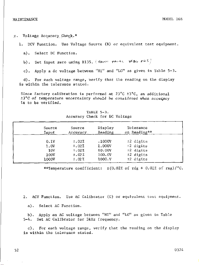
C. Voltage Accuracy Check.*
1. DC” Function. "se Voltage source (B) or equivalent test equipment.
se1ecc DC Function.
a).
see input zero using R135. 8, Flu+. vfic'*,i 3(P.o @I,:
b) .
Apply a dc voltage between "HI" and "LO" a6 given in Table 5-3.
C).
Far each voltage range, verify that the reading on the display
d).
is within the tolerance stared.
Since factory calibration is performed at 23'C +3-C, an additional
*3'C of cemperatore ""certainty should be considered when accqacy
is to be verified.
MODEL 168
Accuracy Check for DC Voltage
source SO”rCe
1npur *CC"raCY Reading
0.1"
1.0" k.O?.%
10" 02%
100"
1ooov
**Temperature coefficient: f(O.OZ% of rdg + 0.01% of mg)/"C.
2. AC” Function.
Select AC Function.
a).
Apply a,, AC voltage between "HI" and "LO" as given in Table
b).
Set AC Calibrator for 5kHz frequency.
5-4.
For each voltage range, verify that the reading on the display
C).
is within the tolerance stated.
Use AC Calibrator (C) or equivalent test equipment.
TABLE 5-3.
02%
k.022 100.0" 52 digits
02 % 1000." 52 digits
DiSplay
.lOOO"
1.000" i2 digirs
10.00" t2 digits
Tolerance
on !&ding**
32 digits
I
52
0374
Page 59

MODEL 168
MAINTENANCE
TABLE 5-4.
Accuracy Check for AC Voltage
source
Input
O.lV
l.OV
1ov
1oov
5oov
f.08%
.lOOOV
t.O8% 1.000”
*.08% 10. oov
?.08%
23
100.0”
500. v
Tolerance
on Reading**
**Temperature coefficient: t<o.o4s of rdg + 0.01% of rnS),“C.
d. Resistance Accuracy Check.
LO OHMS Function. use Resisrance source (D) or equivalent teet
1.
equipment.
Select LO OHMS Function.
a).
Apply a resistance between “HI” and “LO” as given in Table 5-5.
b).
For each resiseance range,
C).
play is within the tolerance stated.
verify that the reading on the dis-
TABLE 5-5.
Accuracy Check for LO OHMS
100 n
1 k.G
10 kn
100 kc!
1 MR
**Temperature coefficient:
?.04%
i.O4%
?.04%
i.O4%
i.O4%
.lOOO k0
1.000 kn
10.00 kll
.lOOO Mn
1.000 MST
+(O.OL% of rdg + 0.01% of mg),“~.
0374 53
Page 60

I
MAINTENANCE
Select HI OHMS function.
a).
Apply a resistance between "HI" and "LO" as given in Table 5-6.
b).
For each resistance range, verify that the reading on.tbe dis-
Cl.
play is within the tolerance stared.
MODEL 168
Accuracy Check fo,i HI OHMS
SO"lXEZ
I*P"t
1 kc?
10 kn
100 kR
1Mn
10 MO
**Temperature coefficient: +(0.04% of rdg + 0.01% of mg)/'C.
Current Accuracy Check.
e.
1. Fuse Protection.
Fuse Check far mA Ranges.
a).
Display should read approximately 1.180kfl to indicate a "goad" fuse.
A blinking display of 0,17Mn indicates a "blown" fuse.
h). Fuse Check for A Ranges.
Display should read approximately .0012kn to indicare a "good" fuse. A
blinking display of 0.17Mn indicates a "blown" fuse.
SO"lXX Display
Accuracy
TABLE 5-6.
Readinn
*.03% 1.000 kfl
03%
+. 03%
+ 03%
A.032 10.00 Ma
10.00 m
100.0 kn
1.000 m
Select "LO OHMS" and %A" functions.
Select "LO OHMS" and "A" functions.
Tolerance
on Reading**
k3 digits
+3 digits
+3 digits
*3 digits
+3 digits
0374
Page 61
MODEL 168
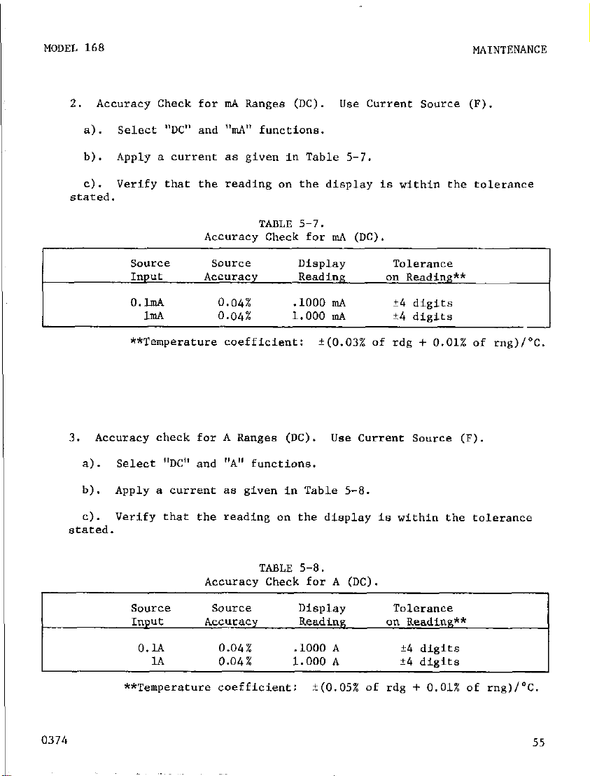
2. Accuracy Check far m.A Ranges (DC). Use Current Source (F).
Select "DC" and "mA" functions.
a).
Apply a current as given in Table 5-7.
b).
c). Verify that the reading on the display is within the tolerance
stated.
MAINTENANCE
Accuracy
Source
Illp"t Accuracy Reading on Reading**
O.hA 0.04% .lOOO UlA
ln!A 0.04% 1.000 InA 14 digits
**Temperature coefficient:
3. Accuracy check for A Ranges (DC). Use Current Source (F).
Select "DC" and "A" functions.
a).
Apply a current a8 given in Table 5-8.
b).
Verify that the reading on the display is within the tolerance
C).
stared.
Source
Accuracv Check for A (DC)
SO”rCe source
Input Accuracy Readin%
TABLE 5-7.
Check for mA (DC).
Display
*(0.03% of rdg + 0.01% of mg)/"C.
TABLE 5-8.
Di.Splay
Tolerance
A4 digits
Tolerance
OrI Reading**
-
0374
O.lA
lA
**Temperature coefficient:
0.04% .lOOO A *4 digits
0.04% 1.000 A
+4 digits
i(O.OS% of rdg + 0.01% of mg)/"C.
55
Page 62
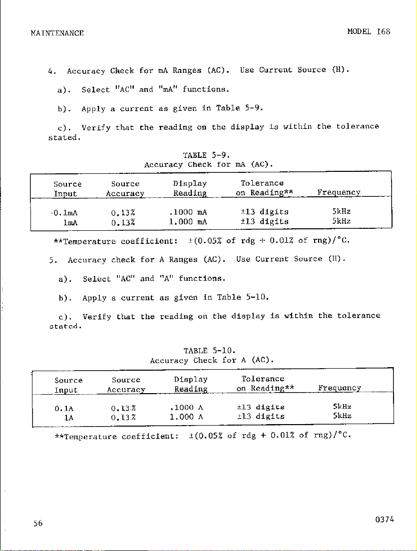
4.
-
I
Accuracy Check for mA Ranges (AC). Use Current Source (H).
select "AC" and "n,A" functions.
a).
b). Apply a current as given in Table 5-9.
c). Verify that rhe reading on the display is within the tolerance
stated.
MODEL 168
Accuracy Check for mA (AC).
Source source Display
-Input ACC"LCy
~O.lmA
ImA
**Temperature coefficient:
5. Accuracy check for A Ranges (AC). Use Current Source (H).
a).
b). Apply a current as given in Table 5-10.
C).
stated.
SO"rCe Source
IllpUt
O.lA
1*
**Temperature coefficient:
0.13%
0.13%
Select "AC" and "A" functions.
Verify that rbe reading on the display is within the tolerance
Accuracy Check for A (AC).
Accuracy
0.13~%
0.13%
TABLE 5-9.
Reading an Reading** Frequency
.lOOO mA
1.000 n!A f13 digits 5kHz
?(O.OS%
TABLE 5-10.
Display
Reading
.lOOO A
1.000 A
i(O.OS% of rdg + 0.01% of mg)/'C.
Tolerance
k13
digits 5kHz
of rdg + 0.01% of mg)/"C.
Tolerance
an Reading** Frequenqi
i13 digits
i-13
digits
5kHz
5kHz
56
0374
Page 63
I
MODEL 168
f. Frequency Response Check.
Select "AC" function.
1.
2. Apply an ac signal using
for a reading of l.OOOV at LOkHz.
3. Maintain a fixed amplitude af the input and checking readings for
frequencies over the range from 20Hz to 1OkHz.
4. Readings should not vary more than f8 digits from 20Hz to 1OkHz.
g. AC Rejection Check.
1. Select "DC function.
2. Connect a 1.5" battery.
3. Apply a 6OHz sine wave using Oscillator (C), in series with battery.
4. set OSCillatOr output for 10" p-p.
Reference oscillator should be transformer coupled 80 that no dc offset is introduce".
5. Reading on the Model 168 should not vary more than il digit.
AC
Calibrator (F) with an amplitude see
NOTE
I
0374
57
Page 64

MAINTENANCE
MODEL 168
ADJUSTMENT/CALIBRATION PROCEDURE.
5-4.
be performed when any specification has been determined fo be out-of-tol-
erance. The Performance Check given in paragraph 5-3 should be performed
prior to this Calibraeion Procedure.
cedure cannot be performed properly, refer to the Troubleshooting Procedure (paragraph 5-5) or contact your Keithley representative or the factory.
chasds Assemblx. To gain access to the adjustments on the printed
*.
circuit board, remove the four slotted screws on the bottom panel as shown
in FiRwe 20.
Care should be taken to avoid contact with line voltages at various
points on the pc board when the line voltage card is connected.
Operate the inetrumenf from battery power (if the Model 1688 Rechargeable Battery Set is available) to minimize the possibility
of e&ecrrical shock when troubleshooting the Model 168.
The Model 1688 may be lifted off the spacers and set fo one side
to gain awes8 to the pc board while operating the Model 168 in
battery mode.
Follow the exact calibration sequence since the adjustments are interrelated and dependent on prior calibration steps. Shield over input
section must be installed for proper calibration. See Figure 23.
Lift off the tap cover and set aside.
CAUTION
IMPORTANT
The following adjustments should
If any step in the Calibration Pro-
NOTE
Recommended Test Equipment For Calibration.
tern
I
J
K
L AC Calibrator
58
Description Specification Mfr.
Digital Volcmerer 1x1" to 1OOOV i 0.1% Keithley
Voltage Source 0 - 1lOOV ?z 0.02% Fluke 341.4
Resistance Source lki? to lOMQ k 0.03%
lm" to lOO0" ? 0.08% Hewlett Packard 745Al746,
TABLE 5-11.
General Radio
2082 to 2OkHz
Model
160
1433
0374
Page 65
I
MODEL 168
MAINTENANCE
0374
Page 66

b. Power Supply Check.
valent test equipment.
Measure dc voltages using Voltmeter (I) or equi-
Battery Check.
1.
made, then check the voltage of each supply directly across the battery
terminals as shown in Figure 6.
2. ~.inr “oltage check.
Connect line cord to 117” i 1” or 234V t 2”, 50-60 Hz.
a).
b). Set IAle Switch to appropriate line voltage range.
set power to LINE.
Cl.
d). Check fuses
3. +5” Regulated Supply. Measure the voltage at f5” af resistor
R131 as shown in Figure 24.
co*on.
4.
in Figure 24.
age should be within the range from -11.4V to -12.6 volts.
The voltage should be within the range from +4.75V to +5.25”.
-12” Regulated supply. maSure the voltage at -12v as shawn
use circuit low an switch hardware as common.
If the calibratLon Is fo be performed using the BAT
FlOl
and FM2 if the display does nof light up.
Use circuit low on twitch hardware a6
The volc-
I
60
0374
Page 67

MODEL
168
DC Voltage Calibration.
C.
Zero Adjustment.
1.
Select "DC" and "A" functions.
a).
Connect Yoltmeter (I) between Input LO and TPl a" the pc board.
b).
(Input terminals of the Model 168 must be open.)
Adjust the front panel zero control (R135) for a zer" reading
C).
on Voltmerer (8) t" within 110 microvolts.
Cannece Voltmeter (I) between Input LO and TP2 on the pc board.
d).
Adjust potentiometer R137 (X10 ZERO) for a zero reading on Volt-
e).
meter (B) to within t100 ml~rov"lfs.
f). Connect a temporary jumper wire between -12 valts and transistor
Q107 (gate lead).
Adjust potentiometer R115 (Xl ZERO) for a zer" reading on Volt-
9).
meter (I) to within ilO microvolts (as measured between I.0 and TPZ).
Remove jumper previously installed in step 6.
h) .
MAINTENANCE
Release
i) .
j). Remove connections to Voltmeter (I).
2. Display Zero Adjust.
a). Apply a -1 milli"olt dc signal to Model 168 input using Voltage
source (J).
b). Adjust potentiometer R129 (DISPLAY ZERO) for a display reading
which flashes between -.0009 volts and -.0010 volts.
3. Rectifier Zero Adjust.
Apply a +I millivolt dc signal to Model 168 input wing Voltage
a).
source (J) ‘
Adjust potentiometer RI26 (RECTIFIER ZERO) for a display resd-
b).
ing which flashes between .0009 voles and .OOlO volts.
2 and 3 to achieve display conditions [so thae n" further adjustmenta
are necessary].)
0374
“A”
pushbutton.
(Repeat step.5
61
Page 68

MAINTENANCE
-100” Adju,e.
4.
Apply a -100 “Olf dc signal to Model 168 inpur using Voltage
a).
source (J).
b). Adjust potentiomefer R128 (-1OOV Adj.) for a display reading
which flashes between -100.0 volts and -100.1 volts.
5. +1oov Adjust.
Apply a +lOO volr dc signal to Model 168 in,mt using Voltage
a).
source (J).
Adjust potentiometer Rl23 (+lOOV Adj.) for a display reading
b).
which flashes between +lOO.O volrs and +100.1 volts.
6. -1" Adjust.
MODEL 168
Apply a -1 volt dc
a).
signal to Model 168 input using Voltage
source (J) .
Adjust potentiometer R139
b).
(-1V
Adj.) for a display reading
which flashes between -1.000 volts and -1.001 volts.
Ohms Calibration.
d.
1. 100 Kilohm Adj.
se1ecr "HI OHMS" function.
a).
Apply 100 kilohm source (0 -LO Model 168 input.
b).
Adjust potentiometer Rl22 (100kn Adj.) for a display reading
Cl.
which flashes befween lOO.OkCZ and lOO.lkR.
2. 1 Kilohm Adj.
a). Apply 1 kilohm source (EC) to
Model 168 input.
b). Adjust potentiometer R109 (lkn Adj.) for a display reading
which flashes between l.OOOkn and l.OOlkn.
62
0374
Page 69

MODEL 168
e. AC Voltage Calibration.
100 VAC Adj.
1.
Select "AC" function.
a).
Apply 100" ac mm at SkHz frequency using AC Calibrator (L).
b).
Adjust capacitor Cl08 (100 "AC Adj.) for a display reading
C).
which flashes between 100.0 and 100.1 voles ac.
2. loom" AC Adj .
a). Apply 1OOmV ac ms at 3kHz frequency using AC CaLibrator (L).
Adjust capacitor Cl10 (1OOmV AC Adj.) for a display reading
b).
which flashes between .lOOO and .lOOl volts ac.
3. 1V AC Adj.
Apply 1V ac rms at Sk& frequency using.AC Calibrator (L).
a).
Adjust capacitor Cl13 (1V AC Adj.) for a display reading which
b).
flashes between 1.000 and 1.001 volts ?c.
MAINTENANCE
I
0374
63
Page 70

MAINTENANCE
MODEL 1,68
open
-.__-
-1m" dc
+lm" dc
-100" dc
+lOO" dc
-1V dc
source
m
_---
-__-
02%
k.O2%
i.O2%
t.o2%
t.02%
Smarv of Calibration hdiustments.
T
-c
TPL set to
0 i lo&L"
TP2 set to
0 :i 1OOW"
+
TP2 set to
0 i 1OO~V
(jumper installed) XI Zero Adj.
-.a009 to
I
-.OOlOV dc
I
+.a009 to
+.OOlO" dc
-100.0 to
-100.1" dc
+100.0 to
+lOO.lV dc
-1.000 to
-1.001" dc
TABLE 5-12.
Display
Reading Name
Adjustment Adjustment
Fronr panel zero
X10 Zero Adj.
-1" Adj.
I
Circuit Desig
I
-__
K139
loom
100” ac Km:
@ SkHz
loom” ac PO
@ 3kHz
1” ac rms
@ 5kHz
i.O3%
-.-
03%
OS%
08%
08%
100.0 to
100. lldl
I
100.1" AC
Page 71

FIGURE 23.
Location of Calibration Adjustments.
0374
65
Page 72

I
MAINTENANCE
MODEL 168
L
66 0374
FIGURE 24. Location Of Test Points.
Page 73
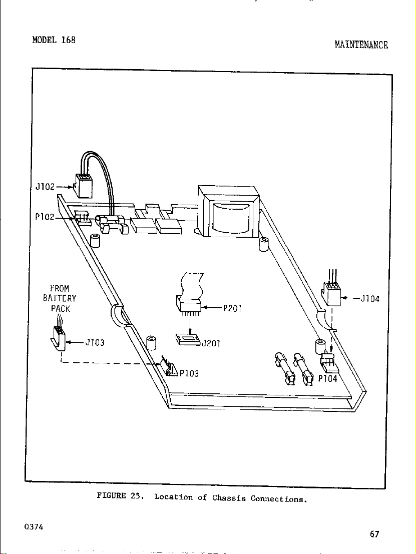
MODEL 168
MAINTENANCE
FROM
BATTERY
PACK
-J
---_
Page 74
MAINTEN‘4NCE
5-5. TROoRI.ESHooTING. If the instrument is out-of-tolerance for any specification, perform the Calibration Procedure given in Paragraph 5-4. If dur-
ing the calibration an instrument mal.function is apparent, then proceed with
the troubleshooting steps as given in Table S-14.
MODEL. 168
a. LLO" to Replace Line Fuses. The Model 168 uses two line fuses in the
primary windings of transfornler T101.
series with winding 4-5-6 for all positions of LINE Switches. Fuse Fl02
(I/R& 3~) is connected in series with winding 1-2-3 only when the Model
168 is set to 117".
board PC-346 as sbom in Figure 26.
board, turn the instrument over so that the bottom cover faces up. Remove
four slorted screw8 on ehe bottom cover.
top cover facing up, taking care to hold fbe top and bottom co"ers together.
Remve the cop cover to gain access to the printed circuit board. Replace
fuses as necessary. Replace top COYer.
bottom cover facing up and install rhe four slotted-tread screws.
How co Replace Batteries. (S ee section 2-3 far installation of Model.
b.
1688 Rechargeable Bateery Pack).
the batteries in the Model 1688 Battery Pack, remove the top cover as in
Section 5-5a (above).
and M-30 as shown in Table 5-13.
Rechargeable "C" cell,
1.2". 4 m-m
Rechargeable %utton" type
battery, 8.4", .25 AMP-
iiK (4 individual 1.2"
cells)
The line fuses are locared on the main prinred ctrcuit
Then replace batteries with Keitbley Part No. M-29
TABLE 5-13.
Summary of Batteries Used in Model 1688.
Description
Fuse PlOl (l/8*, 3hG) is connected in
To gain access t" the printed circuit
Turn over the instrument with
Turn over the insrrument WiCh
If it should ever be necessary to replace
Quanrity
I I
I 7 I
2
Kei~thley Part NO.
RA-30
m-29
C. Troubleshooting Procedure.
5-14 are intended as an aid to locating and correcting circuit malfunctions.
If difficulty is not corrected contact rhe factory or your Keith&' representative for assisrance (see inside front cover for addresses).
68 0374
The troubleshooting hints given in Table
Page 75
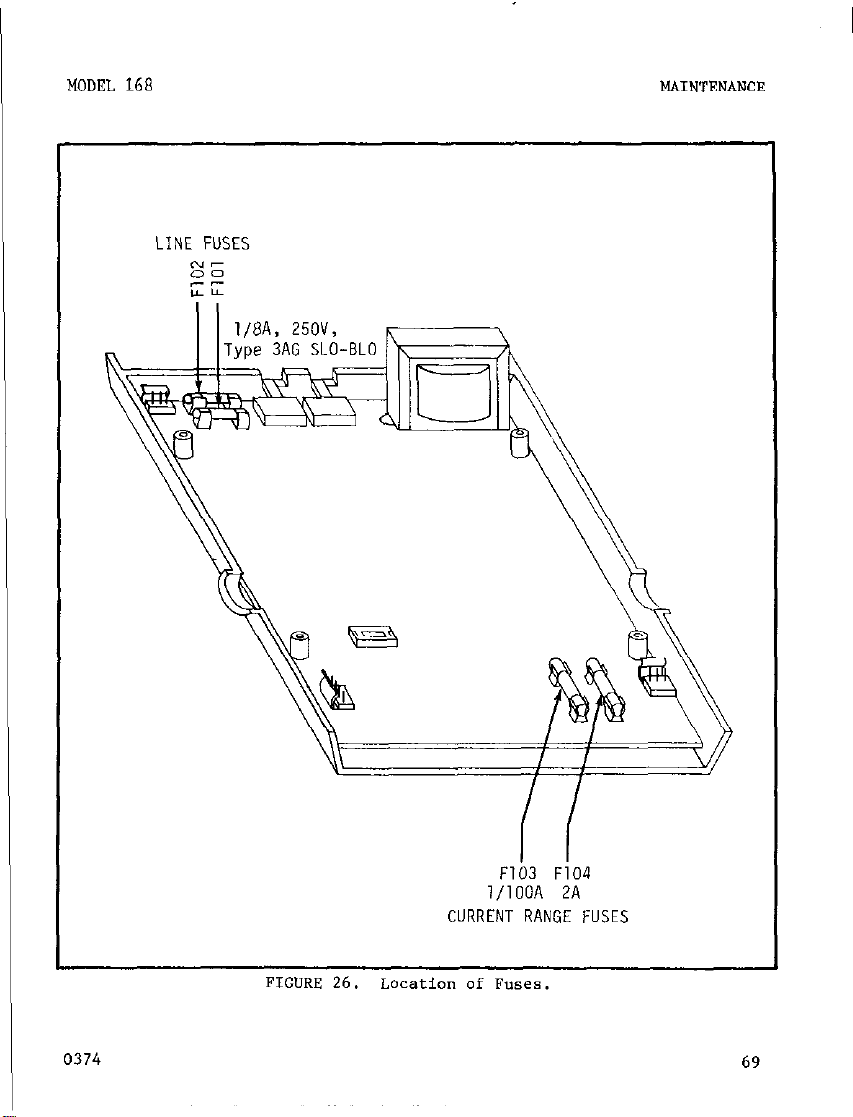
MODEL 168
MAINTENhNCE
LINE FUSES
0374
F103 F104
l/lOOA 2A
69
Page 76

MAINTEtiANCE
MODEL 168
L-
Troubleshooting Procedure
TABLE 5-14.
70
Page 77
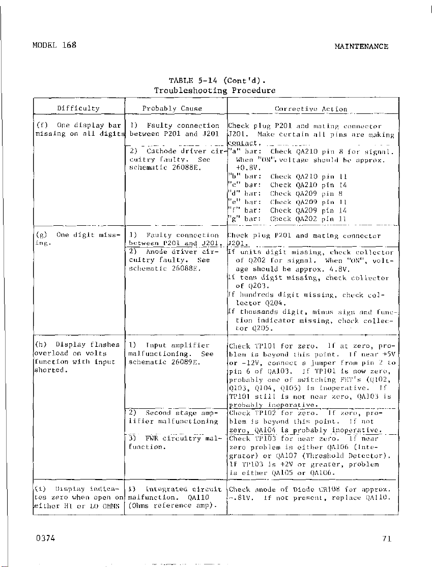
MOOEL 168 MAINTEN‘4NCE
0374
I
71
Page 78
REPLACEABLE PARTS
MODEL 168
SECTION 6.
6-I. GENERAL.
ment parts.
me parts list is arranpec! in alphameric order of their cir-
This section contaiw information for ordering replace-
REPLACEABLE PARTS
cuit Designations.
6-2. ORDERING INFORMATION.
TO place an order or to obtain infarmation
concerning replacement parts, COntact your Kaithley representative or
the factory. see the inside front cover of the manual for addresses.
when ordering, include the following information:
InsCrument Model Number
a.
b. Instrument serial Number
C. Part Description
d. Circuit Designation (if applicable)
e. Keithley Stock Part Number
72
0374
Page 79
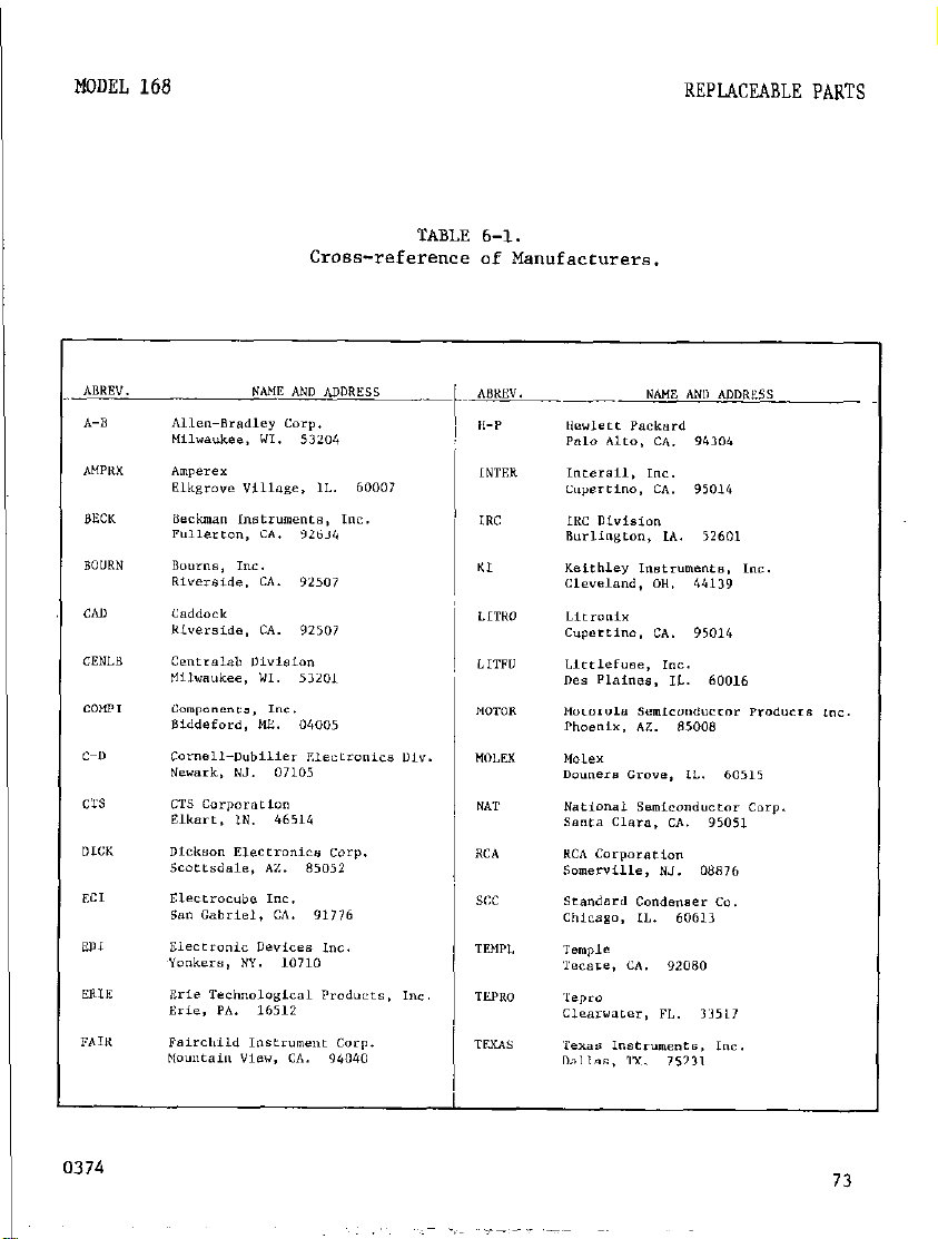
I
MODEL 168
REPLACEABLE PARTS
Cross-reference of Manufacturers.
TABLE 6-1.
Page 80

3
_?tE.~-
.d
0374
Page 81

I
MODEL 168
REPLACEABLE PARTS
Page 82
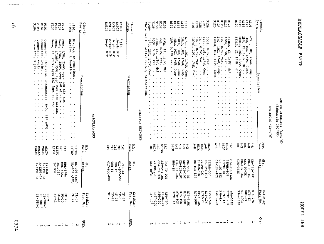
“.‘. !
::: F
E
g j$
: ES
E ;;
^ “Z
“^
ze :g
5 -2
:
Page 83

MODEL 168
a04
‘-7°F. 20”, WT. c:oI
Cl06 t::::: ::: 2:: : : : : : : : : : : : : : :
CZ”,
,,.I,>F, I”“, BTT.
REPLACEABLE PARTS
0374
Page 84

MODEL 168
78
0374
Page 85

KEITHLEY PART NO. IC -31
,EDK TO-116
KEITHLEY PART NO. IC-32
KEITHLEY PART NO. IC- 33
0374
KEITHLEY PART NO. IC- 38
IC-45
Page 86

MODEL 168
KEITHLEY PART NO. IC-42
KEITHLEY PART NO.
K-60
IC-93
KEITHLEY PART NO. IC - 53
KEITHLEY PART NO.
IC-76
80
0374
Page 87
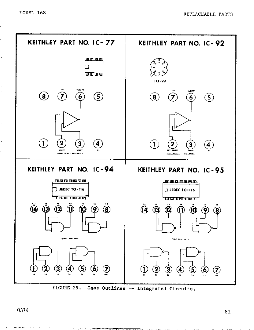
I
MODEL 168
REPLACEABL.E PARTS
Page 88

LEAD DESIG. TO-5
gj fi?J *&J &gj @ qJ
LEAD DESIG. TO-92
TO.5
LEAD DESIG. TO-106
=+$ 2 +$
KEITHLEY PART NO. TG-77
D
IO r
(“4%
Ml0
no/_ “Xl” l~i,y*l,, Pm
-_ “._
i TO-91 :
m- “j%”
KEITHLEY PART NO. TG-88
fy-.d
TO-18
IYIN* “I* Il~l,ylr~i 11.
82
0374
Page 89

I
MODEL 168
REPLACEABLE PARTS
I
TF-5 I
0374
83
Page 90
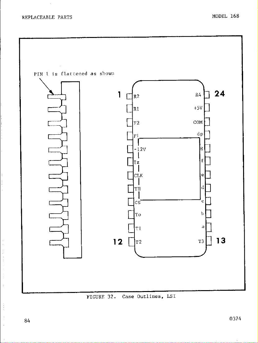
FIGURE 32. case Outlines, LSI
84
0374
Page 91

/ I i
t
Page 92

Page 93
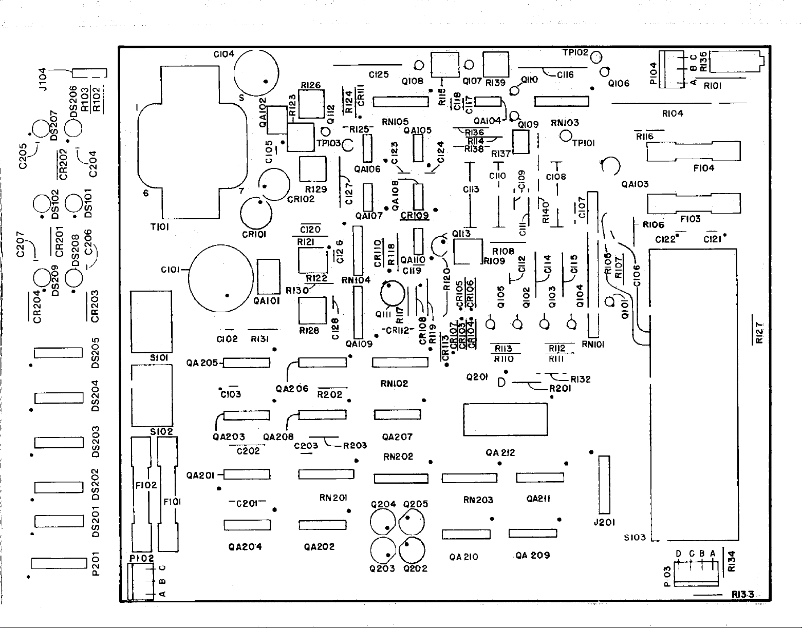
PA103
--
Cl02 RI31
SIOI
s102
‘JA205-j-]
I
OA203 PA206
QA2Ol -I
.
-c201-
I
PA204
c202
I
.
I
WO2OR203
&
PA202
RN201
PA207
0204 0205 RN 203 OA2ll
I I
OA 212
00
60
. .
9203 0202
OA210 .OA 209
.
n
II
J2Ol
0
SlO3
1-l
c,
N
oz
Page 94
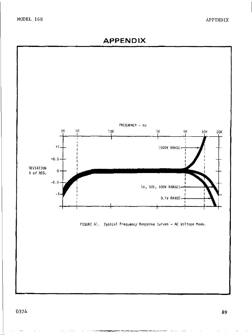
I
MODEL 168
APPENDIX
0371, 89
Page 95
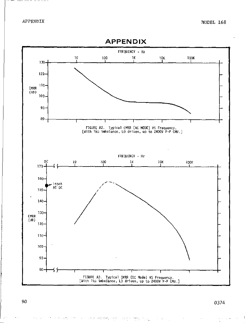
90
0374
 Loading...