

Page 1

xx
TLA7000 Series
ZZZ
Logic Analyzers
Installation Manual
www.tektronix.com
P077174705*
*
077-1747-05
Page 2

Copyright © Tektronix. All rights reserved. Licensed software products are owned by Tektronix or its subsidiaries
or suppliers, and are protected by national copyright laws and international treaty provisions.
Tektronix products are covered by U.S. and foreign patents, issued and pending. Information in this publication
supersedes that in all previously published material. Specifications and price change privileges reserved.
TEKTRONIX and TEK are registered trademarks of Tektronix, Inc.
Contacting Tektronix
Tektronix, Inc.
14150 SW Karl Braun Drive
P.O. Box 5 0 0
Beaverto
USA
For product information, sales, service, and technical support:
n, OR 97077
In North America, call 1-800-833-9200.
Worl dwid e, visi t www.tektronix.com to find contacts in your area.
Page 3

Warranty
Tektronix warrants that this product will be free from defects in materials and workmanship for a period of one (1)
year from the date of shipment. If any such product proves defective during this warranty period, Tektronix, at its
option, either will repair the defective product without charge for parts and labor, or will provide a replacement
in exchange for the defective product. Parts, modules and replacement products used by Tektronix for warranty
work may be n
the property of Tektronix.
ew or reconditioned to like new performance. All replaced parts, m odules and products become
In order to o
the warranty period and make suitable arrangements for the performance of service. Customer shall be responsible
for packaging and shipping the defective product to the service center designated by Tektronix, with shipping
charges prepaid. Tektronix shall pay for the return of the product to Customer if the shipment is to a location within
the country in which the Tektronix service center is located. Customer shall be responsible for paying all shipping
charges, duties, taxes, and any other charges for products returned to any other locations.
This warranty shall not apply to any defect, failure or damage caused by improper use or improper or inadequate
maintenance and care. Tektronix shall not be obligated to furnish service under this warranty a) to repair damage
result
b) to repair damage resulting from improper use or connection t o incompatible equipment; c) to repair any damage
or malfunction caused by the use of non-Tektronix supplies; or d) to service a product that has been modified or
integrated with other products when the effect of such modification or integration increases the time or difficulty
of servicing the product.
THIS WARRANTY IS GIVEN BY TEKTRONIX WITH RESPECT TO THE PRODUCT IN LIEU OF ANY
OTHER WARRANTIES, EXPRESS OR IMPLIED. TEKTRONIX AND ITS VENDORS DISCLAIM ANY
IMPLIED WARRANTIES OF MERCHANTABILITY OR FITNESS FOR A PARTICULAR PURPOSE.
TRONIX’ RESPONSIBILITY TO REPAIR OR REPLACE DEFECTIVE PRODUCTS IS THE SOLE
TEK
AND EXCLUSIVE REMEDY PROVIDED TO THE CUSTOMER FOR BREACH OF THIS WARRANTY.
TEKTRONIX AND ITS VENDORS WILL NOT BE LIABLE FOR ANY INDIRECT, SPECIAL, INCIDENTAL,
OR CONSEQUENTIAL DAMAGES IRRESPECTIVE OF WHETHER TEKTRONIX OR THE VENDOR HAS
ADVANCE NOTICE OF THE POSSIBILITY OF SUCH DAMAGES.
[W2 – 15AUG04]
btain service under this warranty, Customer must notify Tektronix of the defect before the expiration of
ing from attempts by personnel other than Tektronix representatives to install, repair or service the product;
Page 4

Warranty
Tektronix warrants that the media on which this software product is furnished and the encoding of the programs on
the media will be free from defects in materials and workmanship for a period of three (3) months from the date of
shipment. If any such medium or encoding proves defective during the warranty period, Tektronix will provide
a replacement in exchange for the defective medium. Except as to the media on which this software product is
furnished,
Tektronix does not warrant that the functions contained in this software product will meet Customer’s requirements
or that the operation of the programs will be uninterrupted or error-free.
In order to obtain service under this warranty, Customer must notify Tektronix of the defect before the expiration
of the warranty period. If Tektronix is unable to provide a replacement that is free from defects in materials and
workmanship within a reasonable time thereafter, Customer may terminate the license for this software product
and return this software product and any associated materials for credit or refund.
THIS WARRANTY IS GIVEN BY TEKTRONIX WITH RESPECT TO THE PRODUCT IN LIEU OF ANY
OTHER WARRANTIES, EXPRESS OR IMPLIED. TEKTRONIX AND ITS VENDORS DISCLAIM ANY
IMPLIED WARRANTIES OF MERCHANTABILITY OR FITNESS FOR A PARTICULAR PURPOSE.
TEKTRO
PAYMENT IS THE SOLE AND EXCLUSIVE REMEDY PROVIDED TO THE CUSTOMER FOR BREACH
OF THIS WARRANTY. TEKTRONIX AND ITS VENDORS WILL NOT BE LIABLE FOR ANY INDIRECT,
SPECIAL, INCIDENTAL, OR CONSEQUENTIAL DAMAGES IRRESPECTIVE OF WHETHER TEKTRONIX
OR THE VENDOR HAS ADVANCE NOTICE OF THE PO SSIBILITY OF SUCH DAMAGES.
[W9b – 15AUG04]
this software product is provided “as is” without warranty of any kind, either express or implied.
NIX’ RESPONSIBILITY TO REPLACE DEFECTIVE MEDIA OR REFUND CUSTOMER’S
Page 5

Table of Contents
General Safety Summary ........................................................................................ vii
Service Safety Summary.............. .................................. ................................ .......... ix
Preface ............................................................................................................... x
TLA7000 Series Logic Analyzers .................... ................................ ....................... x
Documentation............................................................................................... xii
Basic Installation ................................................................................................... 1
Check the Shipping List................................ ................................ ....................... 1
Site Considerations ............................................................................................ 2
Portable Mainframe Site Considerations .......................... ................................ ..... 2
Benchtop Mainframe Site Considerations.............................................................. 2
Support Hardware Site Considerations ...... .................................. ......................... 3
Installing the Bracket Kit . . ..... . ... . . . .... . ..... . ..... . ..... . .... . ..... . ..... . ..... . .... . . .... . ..... . ..... . .. 4
Chassis Ground Connections .............. .................................. ................................ . 5
Mainframe Configurations .................................................................................... 5
First Time Setup Considerations ........................................................................ 5
Connecting to a Network................................................................................. 6
Networking Overview.................................................................................... 6
Network Security .................... ................................ .................................. ... 7
First Time Network Setup....................................... .................................. ....... 8
Preset IP Addresses ...................................................................................... 10
Instrument Installations .... ................................ .................................. ................ 12
Stand-alone Installation (Portable Mainframe) ....................... ................................ 13
Network Configuration Overview...................................................................... 13
Stand-alone Installation (Benchtop Mainframe)...................................................... 14
Private LAN (Benchtop Mainframe) .................................................................. 18
Corporate LAN (Benchtop Mainframe)... ................................ ............................ 22
Setting up Multiple Mainframe Configurations ........................................................... 27
Expanded System (Two Mainframes) ................................................................. 27
Expanded System (Three to Eight Mainframes).......... ................................ ............ 29
Installing the TLA Application Software on a PC ... . ..... . ... . . . .... . ..... . ..... . ..... . .... . ..... . ..... . 32
Controlling the Logic Analyzer Remotely . .... . . .... . ..... . ..... . ..... ..... . ..... . ..... . ..... . .... . . .... . . 33
Start the TLA Server on the Mainframe............................................................... 33
Connect to the Mainframe .......................... .................................. .................. 34
Changing the TLA7016 Factory Network Settings ... . ..... . ..... . ... . . . .... . ..... . ..... . ..... . ..... 36
Networking Tips & Troubleshooting ......... .................................. ............................ 38
Connecting to the Mainframe........................................................................... 38
Multi-mainframe Systems... . . ..... . ..... . .... . . .... . ..... . ..... . .... . ..... . ..... . .... . . .... . ..... . ..... 39
Adding Location Information for the Connection Dialog Box ..................................... 41
TLA7012 Server Control................................................................................ 42
TLA7000 Series Logic Analyzers Installation Manual i
Page 6

Table of Contents
Installing Mod
Logical Address Switches......................... ................................ ...................... 44
Installing Modules in the Portable Mainframe. . .... . . .... . ..... . ..... . ..... . ..... . ... . . ..... . ..... . .. 45
Installing Modules in the Benchtop Mainframe . . ..... . ..... . ..... . ..... . ... . . . .... . ..... . ..... . ..... 46
Covering Empty Slots ................................................................................... 47
Connecting Accessories............ .................................. ................................ ........ 48
Connecting Accessories to the TLA7000 Series ......... ................................ ............ 48
Additional Accessory Connection Information.... . ..... . ... . . . .... . . .... . ..... . ..... . ..... . ..... . ... 50
Connecting Probes............................................................................................ 51
Connecting Probes to the Logic Analyzer Module....................................... ............ 51
First Time Operation ..................... ................................ .................................. .. 52
Turning the Logic Analyzer On ........................................................................ 52
Turning on Expansion Mainframes .................................................................... 53
Turning off the Mainframes........... ................................ ................................ .. 53
Creating Operating System Restore Discs ....................... .................................. ........ 53
Performing the Incoming Inspection ................. ................................ ...................... 54
Checking the Logic Analyzer Probes (Optional)..................................................... 55
Checking the TLA7000 Mainframe (Optional)....................................................... 55
Backing Up User Files . ................................ ................................ ...................... 55
Removing the Replaceable Hard Disk Drives............................................................. 55
Connecting Probes to the Target System................................................................... 56
Merging Modules............ ................................ .................................. .................... 57
Logic Analyzer Merging Rules.............................................................................. 57
Merge Procedure.............................................................................................. 58
Merging TLA7Axx, TLA7Bxx, or TLA7NAx Modules ................................................. 59
Unmerging TLA7Axx, TLA7Axx, or TLA7NAx Modules.............................................. 62
Merging TLA7Lx/Mx/Nx/Px/Qx Modules .............. .................................. ................ 63
Two-Way Logic Analyzer Merge Procedure................ ................................ .......... 63
Three-Way Merge Procedure . .................................. ................................ ........ 67
Storing the Merge Cable .... ................................ ................................ ............ 68
TLA7Bxx Deskew Procedures................................................................................... 70
Prerequisites ....................... ................................ .................................. .......... 71
Installing the TLACAL Software . ..... . ..... . ... . . . .... . . .... . ..... . ..... . ..... . ..... . ..... . ..... . ..... . ... 71
Deskew Procedure............................................................................................ 72
Product Overview ................... ................................ .................................. ............ 81
Front Panel Controls............................ ................................ .............................. 81
TLA7000 Series External Connectors...................................................................... 81
Connecting an External Display.............................. ................................ .......... 82
Restoring and Reinstalling Software . ..... ..... . ..... . ..... . .... . . .... . ..... . ..... . ... . . ..... . ..... . ... . . . .... . . 83
Restoring the Instrument Operating System ............................... ................................ 83
Restoring the Operating System from the Instrument Hard Disk................................... 83
ules ................ ................................ .................................. .......... 44
ii TLA7000 Series Logic Analyzers Installation Manual
Page 7

Table of Contents
Change the BIOS
Reinstalling the TLA Application Software . .... . ..... . ..... . ..... . ..... ..... . ..... . ..... . ... . . . .... . ..... 85
Calibrate the Touchscreen ................................................................................... 86
Install Other Software............ ................................ .................................. .......... 87
Upgrading or Restoring Firmware ................ ................................ .......................... 87
Upgrading Firmware on TLA7Axx, TLA7Bxx, TLA7Sxx, TLA7SAxx, or TLA7NAx
Modules .............................................................................................. 87
Upgrading Firmware on TLA7Lx/Mx/Nx/Px/Qx/ Dx/7Ex Modules .............................. 89
Upgrading Firmware on the Interface Module and the TL708EX TekLink 8-Port Hub ..... . ... 92
Appendix A: Mainframe Power Information............... .................................. .................. 93
Appendix B: User Service Procedures .......................................................................... 95
Service Offerings ............................................................................................. 95
Warrant
Calibration and Repair Service ....................... .................................. ................ 95
General Care .................................................................................................. 95
Preventive Maintenance.......................... ................................ ............................ 96
Cleaning the Flat Panel Display ........................................................................ 96
Exterior Surfaces......................................................................................... 96
In Ca
Diagnostics ..... .................................. ................................ ........................ 97
Software Problems................................... .................................. .................. 97
Hardware Problems...................................................................................... 98
Repacking for Shipment ..................................................................................... 98
Appendix C: Accessories and Options.... ................................ ................................ ...... 99
cessories .................................................................................................... 99
Ac
Options....................................................................................................... 101
Field Kit Options............................................ ................................ ................ 104
Appendix D: TLA7000 Network Installation Site Survey ............................ ...................... 105
Index
y Repair Service .... ................................ .................................. .......... 95
se of Problems .... ................................ .................................. .................... 97
Settings .. ................................ .................................. .......... 85
TLA7000 Series Logic Analyzers Installation Manual iii
Page 8

Table of Contents
List of Figure
Figure i: TLA7012 Portable Mainframe ................ ................................ ........................ xi
Figure ii: TLA7016 Benchtop Mainframe (with user-supplied PC controller) ............................ xii
Figure 1: Bracket kit for the TL708EX Hub, TLA7PC1 controller and GbE switch installed on a
TLA7016 ....................................................................................................... 4
Figure 2: Location of the ground connection on the TLA7000 logic analyzers.................. ........... 5
Figure 3: Network switch........................................... ................................ .............. 10
Figure 4: TLA7PC1 Benchtop PC Controller.................................................................. 10
Figure 5: Setting the IP address... . ..... . ..... . ..... . ..... . .... . . .... . ..... . ..... . ..... . ..... . ..... . ... . . ..... . .. 11
Figure 6: Portable mainframe setup (up to two modules)........................... .......................... 13
Figure 7: Benchtop mainframe setup (up to six modules) ...................... .............................. 14
Figure 8: LAN Connection dialog box........................ ................................ .................. 15
Figure 9: IP Properties dialog box............................................................................... 16
Figure 10: TLA Connection dialog box......................................................................... 17
Figure 11: TLA Network Search dialog box ................................................................... 17
Figure 12: Benchtop main
Figure 13: LAN Connection dialog box ............ .................................. .......................... 19
Figure 14: IP Properties dialog box ............................................................................. 20
Figure 15: TLA Connection dialog box......................................................................... 21
Figure 16: TLA Network Search dialog box ................................................................... 21
Figure 17: Benchtop mainframe corporate LAN set
Figure 18: LAN Connection dialog box ............ .................................. .......................... 23
Figure 19: IP Properties dialog box ............................................................................. 24
Figure 20: TLA Connection dialog box......................................................................... 25
Figure 21: TLA Network Search dialog box ................................................................... 25
Figure 22: Expanded benchtop system with TekLink cable (up to 12 modules
Figure 23: Two instrument configuration....... .................................. .............................. 28
Figure 24: Expanded benchtop system with TL708EX Hub (up to 48 modules) ................ .......... 29
Figure 25: TL708EX Hub and TekLink cable........................................ .......................... 30
Figure 26: TLA Network Search dialog box ................................................................... 31
Figure 27: Instrument search results ............ ................................ ................................ 32
Figure 28: TLA Connection dialog box......................................................................... 34
Figure 29: TLA Network Search dialog box ................................................................... 35
Figure 30: TLA Configuration dialog box........ .................................. ............................ 36
Figure 31: Make changes to the TLA network settings ..... . ..... . ... . . ..... . ..... . ..... . ..... . ..... . ..... . .. 37
Figure 32: Example of the ping command.......... ................................ ............................ 38
Figure 33: Example of the tracert command ......................... .................................. ........ 39
Figure 34: TLA Network Search dialog box ................................................................... 40
Figure 35: TLA Connection dialog box, search results ....................................................... 41
s
frame private LAN setup (up to six modules) ................................... 18
up (up to six modules) .................. .............. 22
) ..... ...................... 27
iv TLA7000 Series Logic Analyzers Installation Manual
Page 9

Table of Contents
Figure 36: TLA S
Figure 37: TLA Server Properties dialog box............ .................................. .................... 43
Figure 38: Logical address switches (set to address FF) ............ .................................. ........ 45
Figure 39: Installing modules .... . ..... . ..... . .... . ..... . ..... . .... . . .... . ..... . ..... . ... . . ..... . ..... . .... . ..... 47
Figure 40: Installing panel covers on the portable mainframe ..... . ..... . ... . . ..... . ..... . ..... . .... . . .... . . 48
Figure 41: Installing panel covers on the benchtop mainframe ... . ..... . .... . . .... . ..... . ..... . ..... . ..... .. 48
Figure 42: T
Figure 43: TLA7016 accessories connections................ ................................ .................. 50
Figure 44: Connecting the P69xx logic analyzer probes to the TLA7Axx or TLA7Bxx or logic analyzer
module ......................................................................................................... 51
Figure 45: Connecting the P64xx logic analyzer probes to the TLA7Lx/Mx/Nx/Px/Qx logic analyzer
modules ........................................................................................................ 52
Figure 4
Figure 47: Accessing the replaceable hard disk drives...................... .................................. 56
Figure 48: Location of modules in a merged system ............ ................................ .............. 58
Figure 49: Removing the merger connector assembly from the module.................................... 59
Figure 50: Connecting modules in a merged set ..................... ................................ .......... 60
Figure 51: Installing the merged module set in the mainframe. . ... . . ..... . ..... . .... . ..... . ..... . ... . . ..... . 61
Figur
Figure 53: Feeding the merge cable through the cover........................................................ 65
Figure 54: Seating the cover on the chassis .................................................................... 66
Figure 55: Lining up the two modules ............................ ................................ .............. 67
Figure 56: Positioning the merge cable before installing the cover.... . ..... . ..... . ..... . ..... . ..... . ... . . .. 68
Figure 57: TLA7012 with TLA7Bxx module and deskew fixture ........... ................................ 70
Fi
Figure 59: Adjustment procedure dialog box with Deskew selected ................ ........................ 73
Figure 60: Example of adjustment results .......... .................................. .......................... 74
Figure 61: Adjustment procedure dialog box with Merged Deskew selected .............................. 76
Figure 62: Adjustment procedure dialog box with Deskew and Merged Deskew sele cted . ..... . ..... . .. 77
Figure 63: Deskew procedure: Restore Factory Default instructions ....................................... 78
Figure 64: Restore Factory Default settings results . .... . ..... . ..... . ..... . ... . . ..... . ..... . ..... . ... . . . .... . . 79
Figure 65: Portable mainframe front panel ................. ................................ .................... 81
Figure 66: TLA7000 Series external connectors............................................................... 82
Figure 67: Flash programming pins ............................................................................. 90
Figure 68: Maximum power allowed to modules at various line voltages for TLA7016 mainframes serial
6: TLA7000 On/Standby switch locations...................................... ...................... 53
e 52: Removing the cover .................................................................................. 64
gure 58: TLACAL startup window ........................................................................... 73
number B020000 and higher .... ................................ .................................. .......... 94
ystem Properties dialog box................................................................. 42
LA7012 accessories connections...................................... ............................ 49
TLA7000 Series Logic Analyzers Installation Manual v
Page 10

Table of Contents
List of Tables
Table 1: Environmental considerations .......................................................................... 2
Table 2: Por
Table 3: Benchtop mainframe power considerations........ ................................ ................... 3
Table 4: TLA7PC1 and TL708EX power considerations...................................................... 3
Table 5: Mainframe Network Configurations .................... ................................ ............... 6
Table 6: First time network setup...... ................................ .................................. ......... 9
Table 7: Preset IP addresses.............. ................................ .................................. ...... 11
Table 8: A
Table 9: BIOS settings for reinstalling software from the CD-ROM . . ..... . ..... . .... . . .... . ..... . ..... . ... 85
Table 10: TLA firmware files .................................................................................... 91
Table 11: Power for instrument modules ....................................................................... 93
Table 12: Standard accessories, portable mainframe .......... ................................ ................ 99
Table 13: Standard accessories, benchtop mainframe ......................................................... 99
Table
Table 15: Optional accessories, benchtop mainframe ....................................................... 100
Table 16: Optional accessories, Deskew fixture ......... ................................ .................... 100
Table 17: Instrument options................................................................................... 101
Table 18: Power cords ........ .................................. ................................ ................ 102
Table 19: Options for TLA7AC4 modules ................................................................... 103
ble 20: Options for TLA7Bxx modules .................................................................... 103
Ta
Table 21: Options for TLA7BC4 modules.................................... ................................ 104
table mainframe power considerations ............................................................ 2
dditional accessory connection information. . .... . ..... . ..... . ..... . ..... . ..... . ..... . ..... . ..... . . 50
14: Optional accessories, portable mainframe ........ ................................ ................ 100
vi TLA7000 Series Logic Analyzers Installation Manual
Page 11

General Safety Summary
General Safet
To Avoid Fire or Personal
Injury
ySummary
Review the fo
this product or any products connected to it.
To avoid pot
Only qualified personnel should perform service procedures.
While using this product, you may need to access other parts of a larger system.
Read the safety sections of the other component manuals for warnings and
cautions r
Use proper power cord. Use only the power cord specified for this product and
certified for the country of use.
Connect and disconnect properly. Do not connect or disconnect probes or test
leads while they are connected to a voltage source.
Ground the product. This product is grounded through the grounding conductor
of the power cord. To avoid electric shock, the grounding conductor must be
connected to earth ground. Before making connections to the input or output
terminals of the product, ensure that the product is properly grounded.
llowing safety precautions to avoid injury and prevent damage to
ential hazards, use this product only as specified.
elated to operating the system.
Observe all terminal ratings. To avoid fire or shock hazard, observe all ratings
and markings on the product. Consult the product manual for further ratings
information before making connections to the product.
The inputs are not rated for connection to mains or Category II, III , or IV circuits.
Connect the probe reference lead to earth ground only.
Power disconnect. The power cord disconnects the product from the power source.
Do not block the power cord; it must remain accessible to the user at all times.
Do not operate without covers. Do not operate this product with covers or panels
removed.
Do not operate with suspected failures. If you suspect that there is damage to this
product, have it inspected by qualified service personnel.
Avoid exposed circuitry. Do not touch exposed connections and components when
power is present.
Use proper AC adapter. Use only the AC adapter specified for this product.
Use proper fuse. Use only the fuse type and rating specified for this product.
TLA7000 Series Logic Analyzers Installation Manual vii
Page 12
General Safety Summary
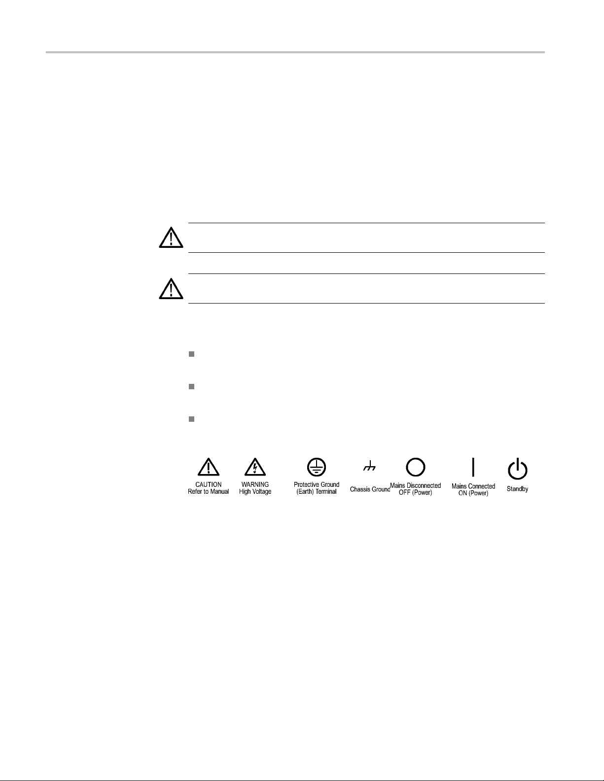
TermsinThisManual
Symbols and Terms on the
Product
Do not operate i
Do not operate in an explosive atmosphere.
Keep product surfaces clean and dry.
Provide prop
details on installing the product so it has proper ventilation.
These terms may appear in this manual:
WARNING.
in injury or loss of life.
CAUTION
damage to this product or other property.
These t
erms may appear on the product:
DANGER indicates an injury hazard immediately accessible as you read
the ma
n wet/damp conditions.
er ventilation. Refer to the manual’s installation instructions for
Warning statements identify conditions or practices that could result
. Caution statements identify conditions or practices that could result in
rking.
WARNING indicates an injury hazard not immediately accessible as you
the marking.
read
CAUTION indicates a hazard to property including the product.
The following symbol(s) may appear on the product:
viii TLA7000 Series Logic Analyzers Installation Manual
Page 13

Service Safety Summary
Service Safet
y Summary
Only qualifie
Safety Summary and the General Safety Summary before performing any service
procedures.
Do Not Service Alone. Do not perform internal service or adjustments of this
product unless another person capable of rendering first aid and resuscitation is
present.
Disconnect Power. To avoid electric shock, switch off the instrument power, then
disconnect the power cord from the mains power.
UseCareWhenServicingWithPowerOn. Dangerousvoltagesorcurrentsmay
exist in
disconnect test leads before removing protective p anels, soldering, or replacing
components.
To avoid electric shock, do not touch exposed connections.
d personnel should perform service procedures. Read this Service
this product. Disconnect power, remove battery (if applicable), and
TLA7000 Series Logic Analyzers Installation Manual ix
Page 14
Preface
Preface
This manual c
and related accessories.
To prevent p
starting service:
The proced
personnel.
Read the Ge
the beginning of this manual.
Be sure t
o follow all warnings, cautions, and notes in this manual.
TLA7000 Series Logic Analyzers
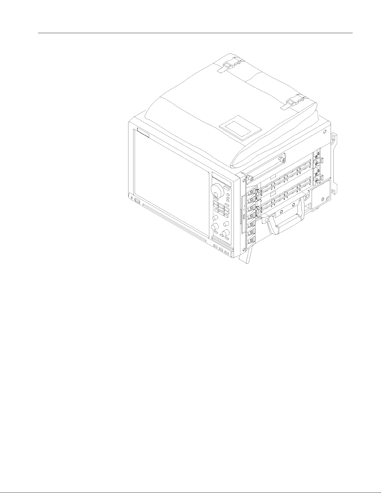
The TLA
(TLA7012) and a 6-module benchtop mainframe (TLA7016).
The TL
(Gb) switch expand the system and connect it to your network. A dedicated PC
controller (TLA7PC1) is available. You can also load the application software
on your PC.
7000 Series Logic Analyzers consist of a 2-module portable mainframe
708EX TekLink 8-Port Hub and a local area network (LAN) gigabit
ontains information needed to install your Tektronix logic analyzer
ersonal injury or damage, consider the following requirements before
ures in this manual should be performed only by qualified service
neral Safety Summary and Service Safety Summary found at
The logic analyzers are built on the Microsoft Windows operating s ystem, which
allows you to install PC-compatible, third-party hardware and software on the
instrument.
The user interface operates under the Microsoft Windows operating system.
Microsoft recommends the following to ensure your instrument is protected:
Use an Internet firewall.
Install operating system updates regularly.
Use up-to-date antivirus software.
The TLA7000 series logic analyzers combine high-performance logic analyzer
modules with optional application modules or an external Tektronix oscilloscope.
x TLA7000 Series Logic Analyzers Installation Manual
Page 15
Preface
Figure i: TLA7012 Portable Mainframe
Several logic analyzer modules are available in various combinations of channel
width, state speed, and memory depth. All of the logic analyzer modules provide
simultaneous state and timing measurements through a single probe.
TLA7000 Series Logic Analyzers Installation Manual xi
Page 16
Preface
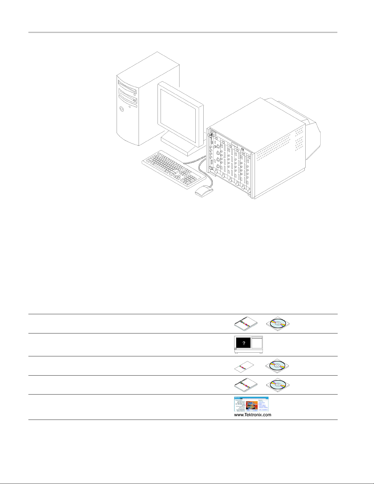
Figure ii: TLA7016 Benchtop Mainframe (with user-supplied PC controller)
Documentation
The following table lists related documentation available for your logic analyzer.
The documentation is available on the TLA Documentation CD and on the
Tektronix Web site (www.tektronix.com/manuals).
For documentation not specified in the table, contact your local Tektronix
representative.
Related Documentation
Item Purpose Location
TLA Quick Start User Manuals
Online Help
Installation Quick Reference Cards High-level installation information
Installation Manuals
High-level operational overview
In-depth operation and UI help
Detailed first-tim e installation information
XYZs of Logic Analyzers
Logic analyzer basics
xii TLA7000 Series Logic Analyzers Installation Manual
Page 17
Related Documentation (cont.)
Item Purpose Location
Declassification and Securities
instructions
Data security concerns specificto
sanitizing or removing memory devices
from Te ktronix products
Preface
Application notes
Product Specifications & Performance
Verification Procedures
TPI.NET Do
Field upgrade kits
Optional Service Manuals Self-service documentation for modules
cumentation
Collection
specific notes
TLA Product specifications and
performance verification procedures
Detailed information for controlling the
logic analyzer using .NET
Upgrade information for your logic
analyzer
and main
of logic analyzer application
frames
TLA7000 Series Logic Analyzers Installation Manual xiii
Page 18

Preface
xiv TLA7000 Series Logic Analyzers Installation Manual
Page 19
Basic Installation
Check the Shipping List
This chapter describes all of the steps needed to install your Tektronix logic
analyzer and its related accessories. It is written from the perspective that you
purchased most of the items uninstalled and you intend to install all of the pieces.
If you purchased a logic analyzer with modules already installed, you should still
review this
chapter and perform the steps that apply to your situation.
Verify tha
shipping list and the accessories list. (See page 99, Accessories.) Also check
for the following:
CAUTION. This notice applies only to the TLA7016 Benchtop Mainframe with
Optio
A special high-current power cord set is provided and is for use exclusively with
this product.
t you have received all of the parts of your logic analyzer using the
Power cords are correct for your geographical area
Correct
Standard accessories
All optional accessories that you ordered
probes and modules
nA6. (SeeTable18onpage102.)
TLA7000 Series Logic Analyzers Installation Manual 1
Page 20
Basic Installation
Site Consider
ations
Read this section before installing the logic analyzer. This section describes
operating considerations and power requirements for your logic analyzer. The
environment
al considerations apply to all TLA7000 series products.
Table 1: Environmental considerations
Feature Description
Temperature
Humidity
20% to 80%
Altitude
CAUTIO
Operating
Nonoperating
Operating ≤30 °C; 80% relative humidity (29 °C maximum wet bulb
Nonoperating
Operating
and
Nonoperating
+5 °C to +45 °C
–20 °C to +60 °C
temperature)
8% to 80% (29 °C maximum wet bulb temperature)
To 3000 m (9843 ft.)
N. Allow a 15.3 cm (6-in) clearance at the top, back, and sides of the
instrument to ensure proper cooling. Avoid blocking any exhaust fans or vents
when using the instrument on a cart or in a rackmount. Inadequate clearances
can cause the instrument to overheat and shut down.
Portable Mainframe Site
iderations
Cons
Benchtop Mainframe Site
Considerations
You can use the portable mainframe on a bench or on a cart in the normal position
the bottom feet). The front feet extend to give a better view of the instrument
(on
display. You can also mount the mainframe in an inst rument rack.
Table 2: Portable mainframe power considerations
Feature Description
ltage range and
Vo
frequency
Input Current 7 A maximum at 90 VAC (70 A surge)
Power Consumption
90 VAC to 250 VAC at 45 Hz to 66 Hz
100 VAC to 132 VAC at 360 Hz to 440 Hz
750 W maximum
The Benchtop Mainframe is designed to operate on a bench, on a cart, or
in a rackmount environment. If you need to stack more than two benchtop
mainframes, install the mainframes in a rack.
WARNING. To avoid personal injury, never lift or move a benchtop mainframe
by yourself. The size and weight of the mainframe requires two people to lift or
move it.
2 TLA7000 Series Logic Analyzers Installation Manual
Page 21

Basic Installation
Support H
Considerations
ardware Site
Do not stack mor
e than one benchtop mainframe on top o f another benchtop
mainframe. Always use a rackmount kit to ensure that the mainframes are secure
and will not fall.
Table 3: Benchtop mainframe power considerations
Feature Description
Voltage range and
frequency
Input Current 16.5 A maximum at 90 VAC (70 A surge)
Power Consumption
90VACto250VACat45Hzto66Hz
100 VAC to 132 VAC at 360 Hz to 440 Hz
1450 W maximum
Refer to the appendix in the back of this manual for mainframe
power consumption information with modules installed. (See
page 93, Mainframe Power Information.)
The TLA7PC1 Benchtop PC Controller, TL708EX Hub, and GbE switch units
can operate separately on your workbench, equipment rack, or cart. You can also
mount them to your benchtop mainframe using the brackets provided with the
op mainframe.
bencht
Table 4: TLA7PC1 and TL708EX power considerations
Product Description
TLA7PC1
TL708EX Voltage
Voltage
range and
frequency
Input
Current
Power
Consumption
range and
frequency
Input
Current
Power
Consumption
100 VAC to 200 VAC at 50 Hz to 66 Hz
3 A m aximum at 100 VAC
300 W maximum
90 VAC to 250 VAC at 45 Hz to 66 Hz
2 A m aximum at 100 VAC
200 W maximum
TLA7000 Series Logic Analyzers Installation Manual 3
Page 22
Basic Installation
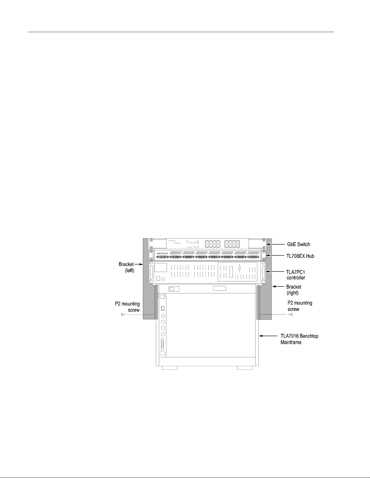
Installing the Bracket Kit
If you are using your benchtop logic analyzer outside of a rackmount environment,
you can use the bracket kit to mount the PC controller, GbE switch, and TL708EX
Hub together with your benchtop mainframe. (See Figure 1 on page 4.) Use
the following procedure:
1. Place the components you want to mount on top of the logic analyzer, putting
2. A left and right-side bracket is included in the kit, along with mounting
the heaviest units lowest in the stack.
screws. Align one of the brackets to the frame of the logic analyzer so that
the brack
height above the top unit.
et reaches all of the components, but minimize the extra bracket
3. Fasten t
screws preinstalled on the bracket.
4. Repeat s
5. If necessary, relocate the instrument brackets on the components you are
mounti
the back of the unit, with installation instructions on the bottom of the unit.
6. Using
components to the brackets.
he bracket to the logic a nalyzer with one of the 8-32, P2 Pozidriv
teps 2 and 3 for the bracket on the other side of the logic analyzer.
ng. For example, the brackets on the TL708EX Hub come mounted to
the 10-32, P2 Pozidriv screws preinstalled on the brackets, fasten the
Figure 1: Bracket kit for the TL708EX Hub, TLA7PC1 controller and GbE switch
installed on a TLA7016
4 TLA7000 Series Logic Analyzers Installation Manual
Page 23
Basic Installation
Chassis Groun
d Connections
Use the chassis ground connections to connect the grounds of the target system
(system-under-test) to the logic analyzer to ensure a common ground connection
between inst
CAUTION. To reduce the risk of ground-loop noise, ground all of the instruments
in the system to the logic analyzer mainframe using the ground connections shown.
ruments. (See Figure 2 on page 5.)
Figure 2: Location of the ground connection on the TLA7000 logic analyzers
Mainframe Confi gurations
Usethissectiontomaketheconnectionsbetween the logic analyzer mainframes
and the support hardware: the controller, network switch, router, and TL708EX
Hub. Then connect the peripheral components such as the display, keyboard, and
other accessories. (See page 48, Connecting Accessories.)
rst Time Setup
Fi
Considerations
The first time you start up your instrument you should decide if you are going to
connect to a network. Plan to connect to a network if you want to:
Share files over the network
Print to a shared printer
Control the instrument remotely
TLA7000 Series Logic Analyzers Installation Manual 5
Page 24

Basic Installation
The TLA7000 ser
ies mainframes can be set up in several configurations,
depending on the number of mainframes you want to use and whether you want
to connect to a network. The following table shows the network configurations
that can be set up.
Table 5: Mainframe Network Configurations
Network Ser
Configuration
Stand-alone — no LAN
connection
Connected to private LAN Only DHCP (no DNS) ConfigurewithDHCP.
Connected to corporate LAN Both DHCP and DNS Configure with DHCP ConfigurewithDHCP
1
Ahostsfile is required to minimize the time needed to resolve IP addresses when DNS (Domain Naming Service) is not available (for example, DNS is often
provided by a Windows Server). (See page 7, TLA7016 Network Search Performance.)
Connecting to a Network
Available
None — stand
If you w
vices
-alone
ant to control the mainframe remotely from your PC, you need to load the
TLA7PC1 or
User-Supplied PC TLA7016
Configure with DHCP. Leave
TCP/IP properties set to
DHCP, but i
connection and thus no DNS
service, Windows assigns
a nonrout
169.254.xxx.xxx
f there is no LAN
able IP address
1
1
ConfigurewithstaticIP.
Recommend nonroutable IP
address 16
preset IP address capability on
TLA7016
Configure with DHCP. Use
router with DHCP service.
9.254.xxx.xxx using
TLA application software. (See page 32, Installing the TLA Application Software
onaPC.) If you use the optional TLA7PC1 PC-based controller, it is preloaded
with the TLA Application software. You may need help from your IT department
or network administrator to complete the network configuration.
Networking Overview
The TLA7000 series instruments communicate between the controller and
mainframes via GbE (gigabit Ethernet) connections using IP (Internet Protocol)
standards. Because of the size of typical TLA data files, GbE components are the
preferred network hardware over more typical 100BaseT networks. Use at l east a
t5e cable for your network connections.
Ca
All connected devices must have unique IP addresses to operate on a network.
his can be achieved by manually entering a static address in the TLA, or if your
T
network has a DHCP (Dynamic Host Control Protocol) server, it can dynamically
provide an address that meets these needs.
6 TLA7000 Series Logic Analyzers Installation Manual
Page 25

Basic Installation
TLA7016 Networ
k Search Performance. The TLA Application software requires a
DNS (Domain Name Service) service to translate TLA7016 host names into IP
addresses. If there is not a DNS service available on the network, then you may
experience long search times when attempting to locate TLA7016 mainframes
on your network.
To eliminate this long search time, Tektronix recommends that you include a hosts
file on your PC under <Windows folder>\system32\drivers\etc directory. (An
example of the contents of this file is shown below.)
120.0.0.1 localhost
192.168.0.19 TLA7016_Lab1
192.168.0.20 TLA7016_Lab2
192.168.0.21 TLA7016_Lab3
TLA IP Address Lease Time. To facilitate reliable network operation,
DHCP-as
signed IP addresses have a "lease time" where they are normally "leased"
to a device for a preset time, for example, one day or one week. After the lease
time expires, the actual IP address may change.
If the lease expires causing an IP change, a ll network connections between the
TLA and host will also expire, stopping network communic ations and causing
the TLA application to terminate. The TLA application must be restarted to
correct this condition.
Network Security
If you plan to operate the TLA application remotely for extended periods of
time (whether acquiring data or not), then lease times must be set to a period of
time that guarantees that the IP address does not change. Talk to your network
inistrator if you have questions.
adm
The user interface on the logic analyzer system operates under the Microsoft
Windows XP Professional Operating System. Tektronix strongly recommends
he following to ensure your instrument is protected:
t
All TLA mainframes are configured to enable the standard Windows XP
rewall by default. Windows provides details for changing firewall settings
fi
in the Control Panel.
Install operating system updates regularly
Use up-to-date antivirus software
NOTE. To use your instrument over a network you must join either a workgroup
or a domain. If you plan to control your instrument remotely, both the instrument
and the remote computer must be in either the same workgroup or the same
domain on the network.
TLA7000 Series Logic Analyzers Installation Manual 7
Page 26
Basic Installation
Ifyouplantoco
from your IT department or network administrator to complete your network
configuration:
Workgroup or Domain name
IP address,
Domain Name Service (DNS)
Other network information from your network administrator
The Teklink/TLA7000 series mainframes require the following services:
DNS
DHCP
Firewall Blocking Network Ports. If you are having problems with any of the
following applications, your firewall may be blocking communications using
the following network ports:
TLA Application - port 111
TPI.NET - port 9000
Windows XP Remote Desktop - port 3389
nnect to a network, you will need the following information
either DHCP (default) or static
First Time Network Setup
NOTE. Tektronix recommends that you conduct a network installation site
survey with the help of your network administrator to determine the networking
requirements. A recommended site survey form is available at the end of this
ument. (See page 105, TLA7000 Network Installation Site Survey.)
doc
Check with your network administrator to determine whether your instrument
ould use the Microsoft Workgroup model or the Microsoft Domain model.
sh
Power on your instrument and use the following table to answer the Windows
questions.
8 TLA7000 Series Logic Analyzers Installation Manual
Page 27

Basic Installation
Table 6: Firs t t
Protect your PC. N/A Choose "Help protect my P C by turning on Automatic Updates
What’s your computer’s
name? (Wait several minutes
after answe
What’s your
password?
Is this co
Enter you
Checkin
connectivity
How wil
connect to the Internet?
Setting up a high-speed
conne
(If LAN is connected) Will
this
Internet directly or through a
network?
(If LAN is not connected)
Win
LAN connectivity
Re
Microsoft
Who will use this computer? Entering names here allows administrator permissions for multiple users on the instrument. By
mputer in a domain?
g your Internet
l this computer
ction
computer connect to the
dows unable to determine
ady to register with
ime network setup
ring)
administrator
r domain settings.
Stand-alone Workgroup Domain
now"
Check with your network administrator for the standard naming convention of your organization. If
your organi
given.
You must have an administrator account to install most software, change the workgroup, perform
Windows updates, or change firewall settings. Check with your network administrator for the
appropria
No (Is giv
N/A Enter the name/password
Press ’S
N/A Choose the appropriate
N/A Enter either the fixed IP/DNS
N/A Choose ’Yes through a
N/A Set up a LAN later. N/A
Windows is already enabled to run on your instrument. This registration is to allow Microsoft
to contact you.
efault, their passwords are blank.
d
zation does not have a naming convention, choose a name that follows the suggestions
te password. The default administrator password on all TLA systems i s blank.
en Workgroup membership)
kip’
Wait for
ork’
netw
this to finish
Yes. Enter the domain name
that your i
onto.
of user who can add the
instrum
answer
assig
administrator or select
"Obtain Automatically".
N/A
nstrument will log
ent to the domain.
ned by your network
The network switch and TLA7PC1 Controller are described below; see your
router manual for specific router information.
Network Switch. The 16 p ort network switch controls the data flow between the
controller and mainframes. Connect the GbE switch between the logic analyzer
mainframe and the TLA7PC1 Controller or an external PC (loaded with the TLA
application). (See Figure 3.)
TLA7000 Series Logic Analyzers Installation Manual 9
Page 28
Basic Installation
Preset IP Addre sses
Figure 3: Netw
TLA7PC1 Benchtop PC Controller. This optional PC-based controller is preloaded
with the TLA Application software and connects to the benchtop mainframe
through the GbE switch. The controller is housed in a 19 in-wide chassis for
mounting to
benchtop mainframe using the benchtop bracket kit. (See page 4, Installing the
Bracket Kit.) The controller includes two removable hard disk trays located
behind a locka ble front door. One tray holds the main hard disk drive. The other
tray can be filled with a SATA hard disk drive provided by the user. (See Figure 4.)
Figure 4: TLA7PC1 Benchtop PC Controller
You may need to change the IP address of the benchtop mainframe(s), depending
on the number of mainframes you have connected in your test system, and the
requirements of the network that it will be connected to.
A preset list of recommended IP addresses is programmed into the benchtop
mainframe. (See Table 7.) You can also set a specificaddress.(Seepage36,
Changing the TLA7016 Factory Network Settings.)
ork switch
your instrument rack. You can also mount the controller to the
10 TLA7000 Series Logic Analyzers Installation Manual
Page 29
Basic Installation
To cycle throug
h the list of preset IP addresses, do the following:
1. Press and hold the reset button on the TLA7016 Interface Module. (See
Figure 5.)
The front-panel display cycles every 2-3 seconds to the next preset address.
(See Table 7
.)
Figure 5: Setting the IP address
2. Release the reset button when the desired address is displayed.
The following addresses are available and displayed sequentially, beginning with
the DHCP selection:
Table 7: Preset IP addresses
Selection IP address Subnet mask
Use: DHCP
Use:
169.254.0.19
Use:
169.254.0.20
Use:
192.168.0.19
Use:
192.168.0.20
Factory default
No change
–– –
169.254.0.19 255.255.0.0 0.0.0.0
169.254.0.20 255.255.0.0 0.0.0.0
192.168.0.19 255.255.0.0 0.0.0.0
192.168.0.20 255.255.0.0 0.0.0.0
–– –
–– –
Default
gateway Comments
IP addressing provided by a DHCP-capable router
Static, non-routable address used for direct PC
connection
Static, non-routable address used for direct PC
connection
Static, non-routable address used for private LAN
with DHCP-capable router
Static, non-routable address used for private LAN
with DHCP-capable router
Return to factory settings (Use DHCP and restore
default Host Name to TLA7016_<Mainframe S/N>)
Retain current IP address and Host Name
TLA7000 Series Logic Analyzers Installation Manual 11
Page 30
Basic Installation
Instrument Installations
The following configurations are described in order of complexity. The most
common setup is as a stand-alone mainframe.
Stand-alone TLA7012 portable
Stand-alone TLA7016 benchtop (requires a separate controller)
TLA7016 ben
TLA7016 benchtop on a corporate LAN
NOTE. You
the controller PC. (See page 32, Installing the TLA Application Software on a PC.)
chtop on a private LAN
must have TLA Application software Version 5.6 or higher installed on
12 TLA7000 Series Logic Analyzers Installation Manual
Page 31

Basic Installation
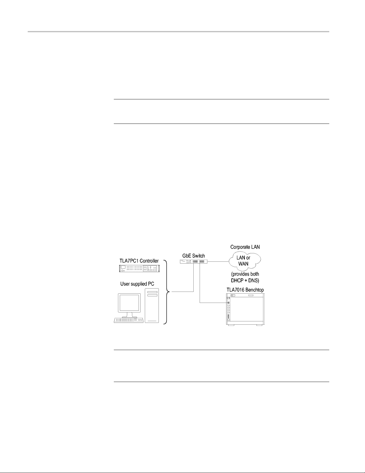
Stand-alone Installation
(Portable Mainframe)
Network Configuration
iew
Overv
If you plan to us
following:
1. Set up the inst
2. Connect the peripheral components that you plan to use. (See page 48,
Connecting
3. Install the modules. (See page 44, Installing Modules.)
4. Refer to the TLA Quick Start User Manual and to the online help for operating
information.
The following figure shows the stand-alone setup for the portable mainframe.
Figure
The benchtop mainframe requires an external PC controller; you can use the
TLA7P
software. The controller and mainframes communicate through Ethernet
connections.
6: Portable mainframe setup (up to two modules)
C1 Benchtop PC Controller or your PC loaded with the TLA application
e the portable mainframe as a stand-alone instrument, do the
rument in a convenient location relative to your target system.
Accessories.)
This section covers configuring your network settings and establishing
communication between the controller and benchtop mainframes. After making
the cable connections, all of the network configuration options generally follow
these steps:
1. Start the controller and mainframe and exit any TLA applications.
2. Establish LAN connectivity using the Windows Networking tools (set the
IP addresses, and if necessary, get user names and passwords from your IT
group).
3. Start the TLA application on the controller.
4. Find and connect to the TLA mainframe through software control.
5. Repeat for all mainframes in the test system.
6. Operate the TLA from the controller or remote computer.
TLA7000 Series Logic Analyzers Installation Manual 13
Page 32

Basic Installation
Stand-alone Installation
(Benchtop Mainframe)
After making co
cable, get the IP addresses to use for the controller and mainframes.
The following
Figure 7: Benchtop mainframe setup (up to six modules)
Configure the PC Controller IP Address to a Static Address. Complete the
following steps to set the IP address of the PC controller as a static address.
1. From the Control Panel on the controller, select Network Connections.
2. Right-
LAN card and select Properties from the menu. The Properties dialog box
appears. (See Figure 8.)
nnections with either a crossover cable (peer-to-peer) or a LAN
figure shows the stand-alone setup for the benchtop mainframe.
click the Local Area Connection icon that corresponds to your local
14 TLA7000 Series Logic Analyzers Installation Manual
Page 33

Basic Installation
Figure 8: LAN Connection dialog box
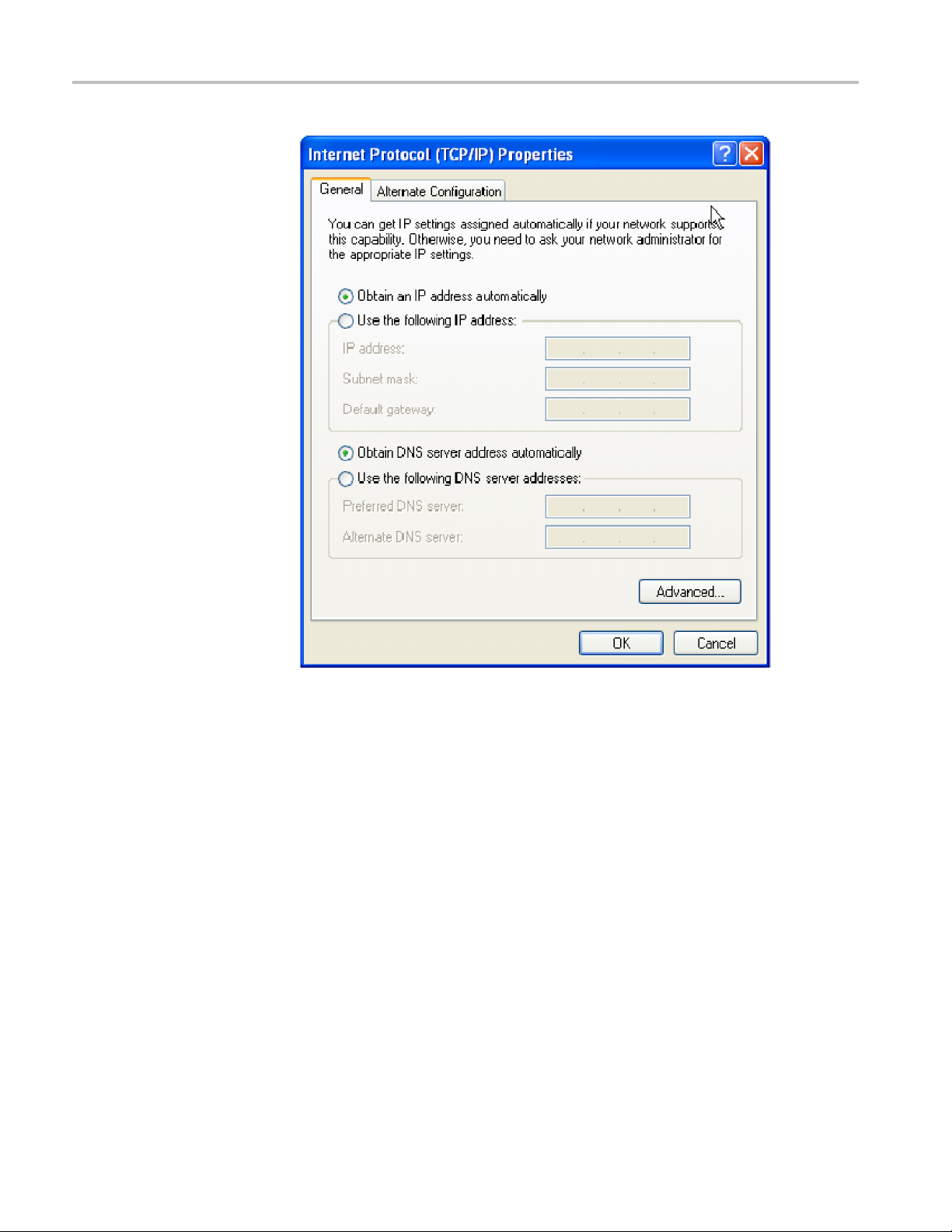
3. Scroll down the list and select Internet Protocol (TCP/IP); and then click
Properties. The Internet Protocol (TCP/IP) Properties dialog appears. (See
Figure 9.)
TLA7000 Series Logic Analyzers Installation Manual 15
Page 34

Basic Installation
Figure 9: IP Properties dialog box
4. Select Use the following IP address.
5. Enter the IP address 169.254.0.22 and Subnet mask 255.255.0.0 for the
controller. No Default gateway or DNS server information is required.
6. Click OK and close the dialog boxes.
Configure the Benchtop Mainframe IP Address to a Static Address.
To complete the setup, set the IP address of the benchtop mainframe as a static
address. You can do this one of t wo ways: use the preset addresses described in
step 7, or specify an address using the Changing the TLA7016 Factory Network
Settings procedure. (See page 36, Changing the TLA7016 Factory Network
Settings.)
7. On the TLA7016 Interface Module, press and hold the RESET button until
the IP address 169.254.0.19 shows in the TLA7016 front panel display. (See
Figure 5 on page 11.) The front-panel display c
next preset address. (See Table 7 on page 11.)
8. Start the TLA application by double-clicking the TLA Application icon on the
controller. The TLA Connection dialog box appears. (See Figure 10.)
ycles every 2-3 seconds to the
16 TLA7000 Series Logic Analyzers Installation Manual
Page 35

Basic Installation
Figure 10: TLA Connection dialog box
9. Select the mainframe in the TLA Connection dialog box, and then click the
Connect button. The application opens on the controller display.
10. If the mainframe is not displayed in the C onnection dialog box:
a. Click
(See Fi
Figure 11: TLA Network Search dialog box
(Searchicon)toopentheTLANetworkSearchdialogbox.
gure 11.)
b. Verify that Locate TLA systems on local subnet is checked.
c. Verify that Include these hostnames or IP in search is checked.
TLA7000 Series Logic Analyzers Installation Manual 17
Page 36

Basic Installation
Private LAN (Benchtop
Mainframe)
d. If you know the h
hosts to search.
e. Click Search.
When the search is complete, the mainframe is listed in the display.
11. Select the mainframe and click the Connect button. The application opens on
the controller display.
12. For information a bout operating your logic analyzer, refer to the TLA Quick
Start User Manual andtotheonlinehelp.
The benchtop mainframe requires an external PC controller; you can use the
TLA7PC1 Benchtop PC Controller o r your PC loaded with the TLA application
software. The controller and mainframes communicate through Ethernet
connections.
You need a GbE network switch for optimum file transfer speed between the
controller and the benchtop mainframe. For stand-alone installations, you must
also connect a router to the network switch to assign IP addresses through DHCP.
Routers can be purchased from other vendors; the D -Link model DI-604 met the
requirements at the time of publication.
The following figure shows the private LAN setup for the benchtop mainframe.
ostname or IP address of the TLA, add it to the list of
Figure 12: Benchtop mainframe private LAN setup (up to six modules)
Configure the Setup. To configure the b enchtop mainframe in a private LAN
setup, do the following:
1. Make the cable connections from the controller, through the switch and router,
to the mainframe.
2. Conn
3. Connect the power cord to the router and power on the router.
4. Connect the power cords and power on the controller and mainframe.
18 TLA7000 Series Logic Analyzers Installation Manual
ect the peripheral components that you plan to use. (See page 48,
Connecting Accessories.)
Page 37

Basic Installation
5. From the Contro
6. Right click the Local Area Connection icon that corresponds to your local
LAN card and se
Figure 13.)
l Panel on the controller, select Network Connections.
lect Properties. The Properties dialog box appears. (See
Figure 13: LAN Connection dialog box
7. Scroll down the list and select Internet Protocol (TCP/IP), and then click
Properties. The Internet Protocol (TCP/IP) Properties dialog box appears.
(See Figure 14.)
TLA7000 Series Logic Analyzers Installation Manual 19
Page 38
Basic Installation
Figure 14: IP Properties dialog box
8. Select Obtain an IP address automatically.
9. Click OK and close the dialog boxes.
10. Start the TLA application by double-clicking the TLA Application icon on the
controller. The TLA Connection dialog box appears. (See Figure 15.)
20 TLA7000 Series Logic Analyzers Installation Manual
Page 39

Basic Installation
Figure 15: TLA Connection dialog box
11. Select the mainframe in the TLA Connection dialog box, and then click the
Connect button. The application opens on the controller display.
12. If the mainframe is not displayed in the C onnection dialog box:
a. Click
(See Fi
Figure 16: TLA Network Search dialog box
(Searchicon)toopentheTLANetworkSearchdialogbox.
gure 16.)
b. Verify that Locate TLA systems on local subnet is checked.
c. Verify that Include these host names or IP in search is checked.
TLA7000 Series Logic Analyzers Installation Manual 21
Page 40
Basic Installation
Corporate LAN (Benchtop
Mainframe)
d. If you know the h
hosts to search.
e. Click Search.
When the search is complete, the mainframe is listed in the display.
NOTE. You may see a delay in the response time if you have more than three
instruments on the LAN. To limit this delay, refer to Multi-mainframe Systems.
(See page 39, Multi-mainframe Systems.)
13. Select the mainframe and click the Connect button. The application opens
the controller display.
14. Refer to the TLA Quick Start User Manual and to the online help for operating
information.
The benchtop mainframe requires an external PC controller; you can use the
TLA7PC1 Benchtop PC Controller o r your PC loaded with the TLA application
software. The controller and mainframes communicate through Ethernet
connections. You need a GbE network switch for optimum file transfer speed
between the controller and the benchtop mainframe.
ost name or IP address of the TLA, add it to the list of
The following figure shows the corporate LAN set
Figure 17: Benchtop mainframe corporate LAN setup (up to six modules)
NOTE. Tektronix recommends that you conduct a network installation site
survey with the help of your network administrator to determine the networking
requirements. A recommended site survey form is available at the end of this
document. (See page 105, TLA7000 Network Installation Site Survey.)
Configure the Setup. To c onfigure the benchtop mainframe in a c orporate LAN
setup, you need to contact your IT Administrator for network information, such
up for the benchtop mainframe.
22 TLA7000 Series Logic Analyzers Installation Manual
Page 41

Basic Installation
as Workgroup or
setting the IP properties for the controller PC and mainframe.
1. Make the cable
2. Power on the equip ment.
3. From the Control Panel on the controller, select Network Connections.
4. Right-click the Local Area Connection icon that corresponds to your local
LAN card and select Properties. The Properties dialog box appears. (See
Figure 18.)
Domain name, and IP address (either static or DHCP) before
interconnections. (See Figure 17.)
ure 18: LAN Connection dialog box
Fig
roll down the list and select Internet Protocol (TCP/IP), and then click
5. Sc
Properties. The Internet Protocol (TCP/IP) Properties dialog appears. (See
Figure 19.)
TLA7000 Series Logic Analyzers Installation Manual 23
Page 42

Basic Installation
Figure 19: IP Properties dialog box
6. Select Obtain an IP address automatically.
7. Click OK and close the dialog boxes.
8. Start the TLA application by double-clicking the TLA Application icon on the
controller. The TLA Connection dialog box appears. (See Figure 20.)
24 TLA7000 Series Logic Analyzers Installation Manual
Page 43

Basic Installation
Figure 20: TLA Connection dialog box
9. Select the mainframe in the TLA Connection dialog box and then click the
Connect button. The application opens on the controller display.
10. If the mainframe is not displayed in the C onnection dialog box:
a. Click
(See Fi
Figure 21: TLA Network Search dialog box
(Searchicon)toopentheTLANetworkSearchdialogbox.
gure 21.)
b. Verify that Locate TLA systems on local subnet is checked.
c. Verify that Include these host names or IP in search is checked.
TLA7000 Series Logic Analyzers Installation Manual 25
Page 44

Basic Installation
d. If you know the h
hosts to search.
e. Click the Sear
When the search is complete, the mainframe is listed in the display.
NOTE. You ma
instruments on the LAN. To limit this delay, refer to Multi-mainframe Systems.
(See page 39, Multi-mainframe Systems.)
11. Select the mainframe and click the Connect button. The application opens
the controller display.
12. Refer to the TLA Quick Start User Manual and to the online help for operating
information.
y see a delay in the response time if you have more than three
ost name or IP address of the TLA, add it to the list of
ch button.
26 TLA7000 Series Logic Analyzers Installation Manual
Page 45

Basic Installation
SettingupMul
Expanded System (Two
Mainfr
tiple Mainframe Configurations
You can con figure your system to link up to eight mainframes together, for a total
of up to 48 modules. The TLA7000 Series mainframes use the TekLink system to
iple-mainframe systems toget her. The TekLink system is described
p mainframes that are connected as expansion mainframes are
on mainframes appear in the System window.
nk cable between the TekLink connectors on the mainframes. (See
ames)
connect mult
here in the two Expanded System sections.
The benchto
automatically powered on in a delayed sequence when the first benchtop or
portable mainframe is powered on. When everything is properly connected and
operational, the expansion mainframe and the installed module icons appear in the
System window.
NOTE. You must have a module installed in the expansion mainframes before the
expansi
Ifyouaregoingtoexpandyoursystemtotwomainframes,youmustconnect
aTekLi
Figure 22.)
nk is a real-time communication system that coordinates trigger signals,
TekLi
input/output signals, and time references between mainframes.
Figure 22: Expanded benchtop system with TekLink cable (up to 12 modules)
CAUTION. TLA7000 Series components are not compatible with TLA7XM
expansion mainframes. If you need to expand your TLA7000 system, use
additional TLA7016 benchtop mainframes, or upgrade your TLA720/721/7XM
expansion mainframe to a TLA7016 with TLA7KUP Option 19.
TLA7000 Series Logic Analyzers Installation Manual 27
Page 46

Basic Installation
Configure the Se
1. Connect the TekLink cable between the host mainframe and the expansion
benchtop main
Teklink cable to expand a portable mainframe to either another portable
mainframe or to a benchtop mainframe.
2. Power on the equipment.
3. Start the TL
controller. The TLA Connection dialog box appears.
4. Select one
5. Click the TLA Configuration icon. The TLA Configuration dialog box
opens. (S
master mainframe and the other as the expansion mainframe.
NOTE. This dialog box is only available if you have two TLA7000 mainframes
connected with a TekLink cable; it is not available if you are using the TL708EX
TekLink 8-Port Hub.
tup. Configure the two instruments as follows:
frame (up to six additional modules). You can also use the
A application by double-clicking the TLA Application icon on the
instrument from the TLA Connection dialog box.
ee Figure 23.) Use this dialog box to assign one instrument as the
Figure 23: Two instrument configuration
6. Refer to your TLA Quick Start User Manual and to the online help for
operating information.
28 TLA7000 Series Logic Analyzers Installation Manual
Page 47

Basic Installation
Expanded System (Three
to Eight Mainframes)
To expand your s
TekLink 8-Port Hub and the TekLink cables. (See Figure 24.) The hub can
accommodate up to eight mainframes (48 modules total).
ystem to more than two mainframes, you must add the TL708EX
Figure 24: Expanded benchtop system with TL708EX Hub (up to 48 modules)
TLA7000 Series Logic Analyzers Installation Manual 29
Page 48

Basic Installation
TL708EX TekLin
rackmount frame. (See Figure 25.) The hub allows you to expand your system to
accommodate up to seven additional TLA7000 Series mainframes, configured as
expansion mainframes (48 modules total).
When you power on the TL708EX TekLink 8-Port Hub, the hub scans the eight
TekLink connectors sequentially. The hub then assigns master mainframe status
to the mainframe that is connected to the lowest number hub connector used (the
#1 connector is used for the master mainframe). The next-highest numbered
hub connec
remaining expansion mainframes that are connected to the hub are assigned
second, third, etc. using this hierarchy.
Configure the Setup. Set up your expanded system by following the steps below.
This power-on sequence must be followed to ensure that the mainframes are
acknowl
1. Connect a TekLink cable from the first mainframe to a TekLink connector
2. Conne
edged by the hub and controller.
on the T
mainframe).
hub to the TekLink connector on your expansion mainframe. Repeat for all
expansion mainframes in your system.
k 8-Port Hub. The TL708EX Hub is housed in a standard 19 inch
tor that y ou use is assigned as the first expansion mainframe. Any
L708EX Hub. (The #1 connector is recommended for the master
ct another TekLink cable from the next TekLink connector on the
3. Connect the power cord to the back of the hub and to an appropriate AC
power source.
Figure 25: TL708EX Hub and TekLink cable
4. Install the modules that you intend to use in the mainframes.
5. Verify that all mainframes are connected to a proper AC source.
6. Connect the power cord to the router and power on the router.
7. Power on the hub.
8. Power on the master mainframe and verify that all of the expansion
mainframes power on. This will take a moment because a sequential power-on
delay is built into the hub.
9. Start the TLA application. The TLA Connection dialog box appears.
30 TLA7000 Series Logic Analyzers Installation Manual
Page 49

Basic Installation
10. Click (Search icon) to open the TLA Network Search dialog box. The
search for instruments returns with thenameofthemainframesthatare
connectedtot
he master mainframe. (See Figure 26.)
Figure 26: TLA Network Search dialog box
You can use the front-panel display on the benchtop mainframe to identify
the IP address and whether it is a Mainframe or Expansion. Press the Next
button on the mainframe front panel until the IP address is displayed. (For
the TLA7012, this information is provided through the TLA Connection
og box).
Dial
11. Click the Configuration icon and verify that the system is configured as
intended. Note that in systems with three or less benchtop mainframes,
you
physically merged modules are not automatically established as a merged set
until you merge them through software. (See Figure 27.)
TLA7000 Series Logic Analyzers Installation Manual 31
Page 50

Basic Installation
Figure 27:
Instrument search results
Installing the TLA Application Software on a PC
The TLA application CD includes the application software that allows you to
control the logic analyzer from a remote PC. Install the TLA application software
on a PC for the following purposes:
To run the TLA application software in the Offline mode.
Control a logic analyzer with the same TLA Application Software over a
network.
Perform the following procedure to install the TLA application software on your
PC for remote operation.
1. Insert the TLA Application Software CD in the CD drive.
2. Bro
wse to the TLA Application SW folder on the CD and run the Setup.exe
program. Follow the on-screen instructions.
you have an older version of the software on the hard disk, the installation
If
program will detect it and ask if you want to remove it. Follow the on-screen
instructions to remove the software, answering "Yes" to any prompts. Do not
cancel the uninstall program, a s this may cause undesirable effects. Restart
the PC when prompted.
32 TLA7000 Series Logic Analyzers Installation Manual
Page 51

Basic Installation
Load Third-Par
PC, you can install the additional third-party software, such as SnagIt, (included
on the TLA Application Software CD).
NOTE. Several third-party software applications are included to u se with your
logic analyzer. These applications may include software license agreements. Be
sure to abide by those license agreements.
Install the NI-GPIB Software. Complete the following steps to install the third–
party software on your PC:
1. Browse to the NI-GPIB-USB folder on the CD and run the Setup.exe program.
2. Follow the on-screen instructions and note the items below:
When prompted, select the Typical installation option.
When the Add GPIB wizard appears, select Cancel.
After restarting the instrument, the NI-488.2 Getting Started wizard
When you first connect the iView cable, the instrument will detect the new
ty Software. After installing the TLA application software on your
displays. This is not needed; select Do not show at Windows startup.
hardware and install the software driver automatically.
Install the SnagIt Software. Complete the following steps to install the SnagIt
software on your PC:
1. Browse to the SnagIt folder on the CD and r
2. Follow the o
n-screen instructions.
Controlling the Logic Analyzer Remotely
After you configure the network
connect and control your logic analyzer from the controller or remote PC. There
are four ways that you can communicate with the mainframe from the controller.
TLA Application — online
TLA Application — offline
Windows Remote Desktop
TPI.NET
Start t he TLA Server on the
Mainframe
The TLA server application must be running on the portable mainframe before
it can be operated over the network from another PC. (The benchtop mainframe
is factory-set to be controlled remotely, so this step is not required.) If you are
setting up a benchtop mainframe, go to Connect to the Mainframe.
un the Setup.exe program.
settings of your system, use this section to
TLA7000 Series Logic Analyzers Installation Manual 33
Page 52

Basic Installation
Connect to
the Mainframe
To start the TLA
1. Right-click
Start TLA Server.
The red circle on the icon disappears, indicating that the server is now running.
2. Configure your PC as described below.
NOTE. You can configure the portable mainframe to start the TLA server when
you turn on the instrument. (See page 42, TLA7012 Server Control.)
To connect to the logic analyzer mainframe from your PC:
1. Start the TLA application by double-clicking the TLA Application icon on the
PC. The TLA Connection dialog box appears. (See Figure 28.)
server on the portable mainframe, do the following:
(TLA server icon, on the right side of the task bar) and select
Figure 28: TLA Connection dialog box
2. Select an instrument in the TLA Connection dialog box and then click the
nect button. You can connect to any instrument on your local network
Con
that is not being used by another user. If no instruments are displayed in
the Connection dialog box:
a. Click
(See Figure 29.)
b. Verify that Locate TLA systems on local subnet is checked.
c. Verify that Include these host names or IP in search is checked.
d. If you know the host name or IP address of the TLA, add it to the list of
hosts to search.
34 TLA7000 Series Logic Analyzers Installation Manual
(Search icon) to open the TLA Network Search dialog box.
Page 53

Figure 29: TLA Network Search dialog box
Basic Installation
e. Click the Search button.
When the search is complete, a list of found TLA systems is displayed,
along with the c urrent status of the system: In Use, Server Down, Blank
able), etc.
(avail
3. Select the mainframe that you wanttoconnecttoandclicktheConnect
n. The application opens on the remote instrument and displays on your
butto
PC. Note that the IP Address identification is shown in the title bar. This
confirms that you have connected to the correct device.
TLA7000 Series Logic Analyzers Installation Manual 35
Page 54

Basic Installation
Changing the TLA7016
Factory Network Settings
The TLA7016 is c
If you want to change these settings, do the following:
1. Connect to the
2. Open TLA Connection dialog box.
3. Click the TLA Configuration icon. The TLA Configuration dialog box opens.
(See Figure 30.)
onfigured for operation on a network that has DHCP and DNS.
TLA7016 mainframe with TLA Application software.
e 30: TLA Configuration dialog box
Figur
4. Selec
t the mainframe that you want to change and click Network Properties.
The Network Properties dialog box appears. (See Figure 31.)
36 TLA7000 Series Logic Analyzers Installation Manual
Page 55

Basic Installation
Figure 31: Make changes to the TLA network settings
5. Make the desired changes and click OK. For example, to change the
mainframe to a static address, click the Use the following Address and enter
the IP address information in the appropriate fields.
TLA7000 Series Logic Analyzers Installation Manual 37
Page 56

Basic Installation
Networking Ti
Connecting t
Mainframe
ps & Troubleshooting
The following tips may help you to make or improve your network connections,
and to optimize your system performance.
othe
If you cannot establish a communication link between the controller and the
mainframe, do the following:
1. Open a Command Prompt window on the controller a nd enter ipconfig.
2. If the above address is not returned, enter ipconfig release and then ipconfig
renew.
3. Press the Next button on the front panel of the TLA7016 until the IP address
is displayed. Use this address to ping the mainframe from the controller.
NOTE. You may need to disable the firewall before performing the ping test.
4. Enter ping xxx.xxx.xxx.xxx (the IP address of the mainframe). The
mainframe should reply to the command. (See Figure 32.)
gure 32: Example of the ping command
Fi
you get a reply using the ping command, yet cannot see the mainframe in
5. If
the configuration dialog box, check to see if a firewall is enabled.
se the tracert command to display the path of the data packets from the
6.U
controller PC to the mainframe. (See Figure 33.)
38 TLA7000 Series Logic Analyzers Installation Manual
Page 57

Figure 33: Example of the tracert command
Basic Installation
Multi-mainframe Systems
If your s
a delay in the response time. This happens when you open the TLA application
or select
approx
were previously identified on the common network are powered off. To minimize
this delay, you can delete the mainframes from the system by doing the follow i ng:
ystem has three or more mainframesonacommonnetwork,youmaysee
(Refresh icon) in the TLA Connection Dialog box. A delay of
imately two seconds occurs for each mainframe if the mainframes that
TLA7000 Series Logic Analyzers Installation Manual 39
Page 58

Basic Installation
1. From the TLA Connection Dialog box, click (Search icon) to open the
TLA Search dialog box. (See Figure 34.)
Figure 34: TLA Network Search dialog box
2. Clear the Locate TLA systems on local subnet selection.
3. If you know the IP address or the name of the system that you are looking
for, do the following:
a. Enter the host name or IP address of your instrument.
b. Click Search.
4. If you don’t know the IP address or the name of the system that you are
looking for, do the following:
a. Click Replace ALL with TLAs found on subnet to display a list of all
instruments on the subnet.
b. Scroll through the list a
in.
c. Click Delete Selection to remove the instruments from the list.
d. Repeat the above steps for all unneeded instruments until you locate your
instrument.
e. Click Search to search for the remaining instruments in the list.
When the search is complete, a list of found, powered-on TLA systems is
displayed. (See Figure 35.) The list also shows the current status, model, and
location of the instruments.
nd select the instruments that you are not interested
40 TLA7000 Series Logic Analyzers Installation Manual
Page 59

Basic Installation
Figure 35: TLA Connection dialog box, search results
NOTE. The list of instruments is a static list; it is not updated automatically. If
you change the status of instruments on the network and experience delays, you
may want to repeat the above steps to improve the system performance.
Adding Location
Information for the
Connection Dialog Box
To help you identify the location of specific mainframes, you can add location
details to each mainframe in the System Properties dialog box:
1. Connect to your logic analyzer.
2. From the System menu, select System Properties. The System Properties
dialog box appears. (See Figure 36.)
TLA7000 Series Logic Analyzers Installation Manual 41
Page 60

Basic Installation
TLA7012 Server Control
Figure 36: TLA System Properties dialog box
3. Add the location details in the Location Info text field.
4. Close t
The location details of the mainframe are displayed in the Connection dialog
box.
The portable mainframe has its own server that must be started if you want to see
the instrument listed on the network. The server control is turned off by default.
To ch
on the instrument, complete the following steps:
1. Right-click the
Properties.
2. Check Launch TLA Server Control during login. (SeeFigure37.)
he dialog box.
ange the server control so that the instrument starts the server when you turn
(TLA Server) icon in the taskbar and select Server
42 TLA7000 Series Logic Analyzers Installation Manual
Page 61

Basic Installation
Figure 37
3. Click OK
If you experience other network connection problems, call the Technical Support
group.
: TLA Server Properties dialog box
.
See Contacting Tektronix in the front of this manual.
TLA7000 Series Logic Analyzers Installation Manual 43
Page 62

Basic Installation
Installing Modules
TLA700 Modules are fully compatible with the TLA7000 Series mainframes. This
section describes how to install TLA700 modules in your TLA7000 mainframe.
CAUTION. To avoid damaging the instrument, do not install or remove any
modules while the instrument is powered on. Always power down the instrument
before inst
alling or removing modules.
Logical Address Switches
Every module in the instrument must have a unique logical address; no two
modules c
of the modules to select the logical address. (See Figure 38 on page 45.)
The fact
dynamic logical address auto configuration, the instrument automatically sets
the address to an unused value.
Normally, you would not want to change the default settings. However, you can
set the address to a fixed static logical address value. You can select any static
addresses between 01 and FE hexadecimal (1 to 254 decimal). If you set the
logical address switches to any other setting than FF, you must verify that no two
modules (or devices) share the same address.
NOTE
reserved exclusively for the controller.
an have the same address. Use the two rotary switches on the rear panel
ory default switch setting is FF (Dynamic Auto Configuration). With
. Do not set any module to logical address 00. Logical address 00 is
44 TLA7000 Series Logic Analyzers Installation Manual
Page 63

Basic Installation
Installing Modules in the
Portable Mainframe
Figure
You can
requires you to merge modules, do so before installing the modules in the
mainframe. (See page 57, Merging Modules.)
You c
not merging the modules, and for air flow considerations, follow these guidelines:
38: Logical address switches (set to address FF)
merge modules together to create wider modules. If your application
an install any of the modules in any slot of the portable mainframe. If you are
tall a single module in slots 3-4. Place a double-width slot cover over
Ins
slots 1-2.
When installing two logic analyzer modules, install the module with the
higher channel count in slots 1-2. Install the module with the lower channel
count in slots 3-4.
When installing two logic analyzer modules with different amounts of
memory, install the module with the larger memory in slots 3-4. Install the
odule with the lower memory in slots 1-2.
m
TLA7000 Series Logic Analyzers Installation Manual 45
Page 64

Basic Installation
Installing Modules in the
Benchtop Mainframe
Install TLA7Lx
install TLA7Axx or TLA7Bxx modules.
When installi
install the oscilloscope module in slots 1-2, and the logic analyzer module
in slots 3-4.
Use a screwdriver to tighten the retaining screws to 2.5 in-lbs after se ating the
modulesinplace.(SeeFigure39onpage47.)
You can ins
intend to merge the modules, disregard the following suggestions and refer to the
merging m odules rules. (See page 57, Merging Modules.) If you are not merging
the modules, and for airflow considerations, follow these guidelines:
Install a single module in slots 1-2. Place a double-width slot cover over
slots 3-4, 5-6, 7-8, 9-10, and 11-12.
When installing two or more logic analyzer modules, install the module with
the highest channel count in slots 1-2. Install the module with the lower
channel count in slots 3-4. Place double-width slot covers over slots 5-6,
7-8, 9-10, and 11-12.
When installing two or more logic analyzer modules with different amounts
of memory, install the module with the largest memory in slots 1-2. Install the
modu
over slots 5-6, 7-8, 9-10, and 11-12.
tall any of the modules in any slot of the b enchtop mainframe. If you
le with the lower memory in slots 3-4. Place double-width slot covers
/Mx/Nx/Px/Qx modules or TLA7Dx/Ex modules before you
ng a logic analyzer module with an oscilloscope module,
tall TLA7Lx/Mx/Nx/Px/Qx modules or TLA7Dx/Ex modules, before you
Ins
install TLA7Axx or TLA7Bxx modules.
en installing a logic analyzer module with an oscilloscope module,
Wh
install the logic analyzer module in slots 1-2 and the oscilloscope module in
slots 3-4. Place double-width slot covers over slots 5-6, 7-8, 9-10, and 11-12.
In systems with three or less benchtop mainframes, physically merged
modules are not automatically established as a merged set until you merge
them through software.
Use a screwdriver to tighten the retaining screws to 2.5 in-lbs after se ating the
modulesinplace.(SeeFigure39onpage47.)
46 TLA7000 Series Logic Analyzers Installation Manual
Page 65

Basic Installation
Covering Empty Slots
Figure
If you have any unused (empty) slots in your mainframe, install blank-slot panel
cover
for the empty slot in the Portable Mainframe. (See Figure 40.) Install the blank
slot-panels on the benchtop mainframe. (See Figure 41.) Install the blank-slot
panel covers before any modules. Use only Tektronix TLA covers; otherwise the
mainframe may not meet EMC and cooling requirements.
Make sure that the EMI shielding is in contact with the adjacent panel or module
cover, and that the airflow shutter activation arms protrude through the holes
in the blank-slot panel.
39: Installing modules
s to meet EMC and cooling specifications. Install a blank-slot panel cover
TLA7000 Series Logic Analyzers Installation Manual 47
Page 66

Basic Installation
Figure 40: Installing panel covers on the portable mainframe
re 41: Installing panel c overs on the benchtop mainframe
Figu
Connecting Accessories
After installing the mainframes and modules, you can connect the accessories
such as external monitors, keyboard, and printer.
nnect the accessories to the Portable Mainframe. (See Figure 42.) If you have a
Connecting Accessories to
the TLA7000 Series
48 TLA7000 Series Logic Analyzers Installation Manual
Co
benchtop mainframe, connect the accessories to external PC; connect other cables
and connectors to the benchtop mainframe. (See Figure 43 on page 50.)
Page 67

Basic Installation
Figure 42: TLA7012 accessories connections
TLA7000 Series Logic Analyzers Installation Manual 49
Page 68

Basic Installation
Figure 43: TLA7016 accessories connections
Additional Accessory
Connect additional accessories as needed. (See Table 8.)
Connection Information
Table 8: Additional accessory connection information
Item Description
Monitor
LAN
nter
Pri
There are two display ports on the TLA7012: Primary (DVI-D, digital output only), and Secondary (DVI-I,
l/analog out). Simulscan mode displays the same information on the internal display and the
digita
external monitor connected to either Primary or Secondary.
To change the display settings, right-click the mouse on the desktop, select Properties, and go to the
ngs tab. Select the settings for your monitor. Note that some of the display settings may not
Setti
function until you connect an external monitor.
Use the VGA-to-DVI display adapter to connect a VGA monitor to the Secondary DVI-D output. Part
ers for accessories and options are listed at the end of this manual. (See page 99, Accessories
numb
and Options.) If you use a nonstandard monitor, you may need to change the Windows display settings
to achieve the proper resolution.
Connect the mainframes to your network through the Gbit LAN connectors. You can remotely control
mainframes through a LAN switch using your PC (loaded with the TLA application software), or the
the
dedicated PC controller ( TLA 7PC1).
The instruments send printer information to the USB ports. Use any of the four USB ports for your printer.
50 TLA7000 Series Logic Analyzers Installation Manual
Page 69

Basic Installation
Connecting Pr
obes
Connecting Probes to the
Logic Analyzer Module
After you have connected all the accessories, you can connect the probes to the
instrument. Refer to the appropriate section for your instrument.
For additional information on the individual probes, refer to the instructions that
accompanied your probes.
CAUTION. Wh
evenly tighten probe screws until they are snug. First slightly tighten screws, then
snug each screw to 4 in-lbs (maximum). Under tightening the probe screws can
result in intermittence. Over tightening can result in stripped screws.
Connect the logic analyzer probes to the logic analyzer modules.
en attaching the probe to the logic analyzer, you must use care to
Figure 44: Connecting the P69xx logic analyzer probes to the TLA7Axx or TLA7Bxx
or logic analyzer module
TLA7000 Series Logic Analyzers Installation Manual 51
Page 70

Basic Installation
First T
ime Operation
Turning the Logic Analyzer
On
Figure 45: Connecting the P64xx logic analyzer probes to the TLA7Lx/Mx/Nx/Px/Qx
logic analyzer modules
Use the information in this section to turn on the logic analyzer for the first time.
CAUTION. Connecting the accessories after turning on the logic analyzer may
ge the accessories. Connect accessories before applying power to the logic
dama
analyzer.
low these steps to turn the logic analyzer on:
Fol
1. Connect the power cord to your instrument.
2. If you have an external monitor, connect the power cord and turn on the
monitor.
3. Press the On/Standby switch to turn o n the mainframe. (See Figure 46.)
4. Wait for the mainframe to complete the power-on self tests.
52 TLA7000 Series Logic Analyzers Installation Manual
Page 71

Figure 46: TLA7000 On/Standby switch locations
Basic Installation
Turning on Expansion
Mainframes
Turning off the Mainframes
eating Operating System Restore Discs
Cr
The benchtop mainframes that are connected as expansion mainframes are
automatically powered on when the first benchtop or p ortable mainframe is
powered on. If everything is properly connected and operational, you will see the
expansion mainframe and the installed modules in the System window.
NOTE. Y
expansion mainframe appears in the System window.
To po
Both the portable and benchtop mainframes have a built-in soft power-off function
that safely powers off the mainframe when you press the On/Standby switch. The
expansion mainframes automatically power off when you turn off the benchtop
or portable mainframe.
The instrument does not ship with an operating system restore disc. Use the
following procedure to create a set of discs that enable you to restore the operating
ystem if the need arises.
s
ou must have a module installed in an expansion mainframe before the
weroffthemainframes,presstheOn/Standby switch on the mainframe.
NOTE. This procedure creates a set of restore discs for the Microsoft Windows
operating system. After restoring the operating system, use the TLA A pplication
disc to reinstall the TLA application software. (See page 85, Reinstalling the TLA
Application Software.)
TLA7000 Series Logic Analyzers Installation Manual 53
Page 72

Basic Installation
Complete the fo
discs (one for each backup file).
1. Insert a b lank
2. Click Start > All Programs > Nero 7 Essentials > Data > Nero Express
Essentials
3. Click Image, Project, Copy.
4. Click Disk Image or Saved Project.
5. Navigate to C:\backup.
6. Select file backup1 and click Open.
7. Click the Verify data on disk after burning check box to enable this function.
8. Click th
then verifies that the data matche s the source file.
9. When th
successfully, remove the disc and label it appropriately (include backup file
name, instrument na me, instrument serial number, and date).
10. Copy the disk image files (*.iso) located in the C:\backup directory to a
network location, a separate hard disk, or optical media for backup purposes.
llowing steps to create a set of restore discs. You will need blank
disc in the instrument DVD drive.
.
e Burn button. The application writes the backup file to the disc and
e application reports that the write process has completed
11. Store the backup discs as defined by y our company policy.
NOTE. You can only use restore discs on the instrument that created them.
forming the Incoming Inspection
Per
Incoming inspection consists of verifying the basic operation of the logic analyzer.
The power-on diagnostics check the basic functionality. The diagnostics run
ery time you turn on the logic analyzer.
ev
You can also verify more detailed functionality by running the self-calibration and
xtended diagnostics.
e
NOTE. Allow the mainframe and modules to warm up for 30 minutes before
running the self-calibration.
54 TLA7000 Series Logic Analyzers Installation Manual
Page 73

Basic Installation
Checking the Logic
Analyzer Probes (Optional)
Checking the TLA7000
Mainframe (Optional)
To run self-cal
1. Disconnect any probes attached to the modules.
2. Select the System menu and click Calibration and Diagnostics.
3. Run the self-calibration, and then run the extended diagnostics by selecting
the proper tab. Results of the tests display on the individual property page.
NOTE. The time required to run the self-calibration on the logic analyzer modules
depends on
channels may take several minutes to run the self-calibration.
Connect the logic analyzer probes to a signal source and (if necessary) adjust the
threshold levels for the probes to acquire the signals. Use the threshold and activity
indicators in the LA Setup window to verify signal a ctivity at the probe tips.
To check the mainframe diagnostics not covered by the TLA Application software,
run the TLA7000 Mainframe Diagnostics located under the Windows Start menu
(Start/Programs/Tektronix Logic Analyzer/TLA Mainframe Diagnostics). Exit the
TLA Application before running the external diagnostics.
ibration and diagnostics, perform the following:
the number of acquisition channels. Modules with a large number of
Backi
ng Up User Files
Back up your user files on a regular basis. Use the Windows back up tools or copy
the files to another media. Always keep a backup copy of files that you access
regular basis.
on a
Removing the Replaceable Hard Disk Drives
CAUTION. To avoid permanently damaging the replaceable hard disk drive, do
not remove it while the instrument is powered on. Always power off the instrument
before removing the hard disk drive.
1. Verify that the instrument is powered off.
2. Open the access door (TLA7PC1 only).
3. Pull out the lever (TLA7PC1), or unscrew the locking thumbscrews
(TLA7012). (See Figure 47.)
4. Pull on the replaceable hard disk drive cartridge to remove it from the chassis.
TLA7000 Series Logic Analyzers Installation Manual 55
Page 74

Basic Installation
Figure 47: Accessing the replaceable hard disk drives
Connecting Probes to the Target System
The logic analyzer connects to the target system through the probes. The logic
analyzer probes allow you to connect to the target system in s everal different
ways. For probe-specific connection details, refer to the appropriate probe
uction manual or browse through the Tektronix Web site.
instr
56 TLA7000 Series Logic Analyzers Installation Manual
Page 75

Merging Modules
A merged logic analyzer module set consists of a m aster logic analyzer module
and up to four slave logic analyzer modules that are physically connected together
by a merge cable and are merged in software. Review the guidelines under Logic
Analyzer Module Merging Rules, and then follow the steps to physically connect
the modules
Logic Analyzer Merging Rules
The following logic analyzer module merging rules must be followed:
The TLA7BB2 Logic Analyzer Module is the only 68-channel module that can
be merged. For other modules, 102 or 136 channel modules can be merged.
Logic analyzer modules must be in adjacent slots and physically connected.
Logic analyzer modules cannot be merged across mainframes (between the
benchtop mainframe and one or more expansion mainframes).
Merging logic analyzer modules with unequal memory depths will result in
the merged modules assuming the depth of the shallowest module.
When merging logic a nalyzer modules of unequal channel widths, use the
logic analyzer module with the highest number of channels as the master
module. If there is a second slave module, the first slave must have at least
as many channels as the second slave module. Slave 3 cannot have more
channels than the master, slave 1 or slave 2. Slave 4 cannot have more
channels than the master, slave 1, slave 2, or slave 3.
together before installing the modules in the mainframe.
The logic analyzer modules must have the same firmware version.
The maximum merged combinations are two TLA7Lx and TLA7Mx modules;
three TLA7Nx, TLA7Px, or TLA7Qx modules; five TLA7Axx modules, five
TLA7Bxx modules, or five TLA7NAx modules.
TLA7Nx, TLA7Px, and TLA7Qx modules cannot be merged with TLA7Lx
or TLA7Mx modules.
TLA7Bxx modules cannot be merged with TLA7Nx, TLA7Px, TLA7Qx,
TLA7Lx, TLA7Mx, or TLA7Axx modules.
TLA7Axx modules cannot be merged with TLA7Nx, TLA7Px, TLA7Qx,
TLA7Lx, TLA7Mx, or TLA7Bxx modules.
To merge a logic analyzer module to an established merged set, the established
merged set must first be unmerged through software. Unmerged modules are
the only potential candidates to add to a merged configuration.
In systems with three or fewer benchtop mainframes, physically merged
modules are not automatically established as a merged set until you merge
them through software.
TLA7000 Series Logic Analyzers Installation Manual 57
Page 76

Merging Modules
Merge Procedure
Complete the following steps to create a merged module from two or more
individual modules. You must complete these steps prior to installing the modules
in a mainframe.
CAUTION. To avoid damaging the mainframe or any modules, always power off
the mainfra
1. Determine which modules will reside in the highest-numbered slots in a
single mai
2. Place the merge connector of these modules in the extended position. The
module in
recessed position.
me before removing or installing modules.
nframe.
the lowest-numbered slot must have the merge connector in the
The foll
master module with the merged module set. (See Figure 48.) Even though the
figure shows a five module set, you can still use it to position the master module
with respect to the slave module. If you have a two module set, the master
module is located in the lower-numbered slot, and the slave module is in the
higher-numbered slot.
igure 48: Location of modules in a merged system
F
owing figure shows an example for determining the location of the
58 TLA7000 Series Logic Analyzers Installation Manual
Page 77

Merging TLA7Axx, TLA7Bxx, or TLA7NAx Modules
Complete the following steps to create a merged module from two to five
individual TLA7Axx or TLA7NAx modules.
1. Place the module on the right side.
2. Using a Torx T-10 screwdriver, remove the two screws holding the merge
connector to the module. (See Figure 49.)
Merging Modules
Figure 49: Removing the merger connector assembly from the module
3. Gently lift the merge connector out of the slot and place it in the extended
position such that the screw holes line up over the two standoff posts.
TLA7000 Series Logic Analyzers Installation Manual 59
Page 78

Merging Modules
4. Install the two
5. Repeat steps 1 through 4 for the remaining modules.
NOTE. When in
help of another person.
6. Place the fir
connector assemblies line up between the two modules. (See Figure 50.)
7. Push the tw
8. Add any additional modules to the set.
screws into the standoff posts. Tighten the screws to 4-in. lbs.
stalling the merged modules into a mainframe, you may need the
st pair of modules to be m erged side-by-side such that the merge
o modules together until the connectors are seated in place.
Figure 50: Connecting modules in a merged set
CAUTION. Ensure that the mainframe is powered-off before installing or removing
the modules. Failure to do so can damage the mainframe or the modules.
9. Place the merged module set into the mainframe.
10. Align the tops and bottoms of the modules with the slots in the mainframe.
(See Figure 51 on page 61.) You may need the help of another person if your
merged module set contains more than two modules.
60 TLA7000 Series Logic Analyzers Installation Manual
Page 79

Merging Modules
Figure 51: Installing the merged module set in the mainframe
TLA7000 Series Logic Analyzers Installation Manual 61
Page 80

Merging Modules
11. Slide the modul
rear panel connectors.
12. Use the inject
The merge cable assembly should allow enough movement between two
side-by-side modules to allow you to seat or unseat them individually.
13. Tighten the four retaining screws on each module to 2.5-in. lbs.
14. After insta
the merge process listed under the Merged Modules tab in the System
Configuration dialog box.
es all the way into the mainframe until they rest against the
or handles to firmly seat the modules in place one at a time.
lling all of the modules, power on the mainframe and complete
Unmerging TLA7Axx, TLA7Axx, or TLA7NAx Modules
Although you can unmerge modules from a merged set from within the TLA
application without physically separating modules, there will be times when you
have to physically unmerge the modules. The following procedures provide the
steps for unmerging the modules.
CAUTIO
the modules. Failure to do so can damage the mainframe or the modules.
N. Ensure that the mainframe is powered-off before installing or removing
1. Powe
2. Loosen the four retaining screws on each module.
3. Use the ejector handles to disengage each module in the merged module set
4. With the assistance of another person, slide all of the merged modules out of
5. Gently separate the modules one at a time from the merged module set.
6. Lay the modules on their right sides.
7. Remove the two Torx T-10 screws that hold the merge cable assembly to
8. Place the merge cable assembly into the recessed position.
9. Install the two Torx T-10 screws onto the assembly and tighten the screws to
10. Repeat steps 7 through 9 for the other modules.
You can now reinstall the modules in the mainframe as needed.
r off the mainframe before removing the modules from the mainframe.
from the mainframe.
the mainframe and place them on a static-free working surface.
the module.
4in-lbs.
62 TLA7000 Series Logic Analyzers Installation Manual
Page 81

Merging Modules
Merging TLA7L
x/Mx/Nx/Px/Qx Modules
Two-Way Logic Analyzer
Merge Procedure
Use the following procedures to physically merge the logic analyzer modules
together.
CAUTION. En
the modules. Failure to do so can damage the mainframe or the modules.
Use the fol
merge three modules. (See page 67, Three-Way Merge Procedure.)
CAUTION. Static discharge can damage any semiconductor component in the
logic analyzer module.
Discharge the static voltage from your body by wearing a grounded antistatic
wrist strap while performing the merge procedure.
Perform the following steps to merge two modules:
1. If you have not already done so, power off the mainframe and remove the
modules that you want to merge together.
sure that the mainframe is powered-off before installing or removing
lowing procedure to merge two logic analyzer modules. You can also
2. Determine which module will be designated as the slave module and which
module will be the master module.
3. Lay the slave module on the right side (as viewed from the front panel).
4. Rem
5. Re
6. Remove the screws holding the merge cable bracket to the cover.
7. Remove the top part of the cable bracket and set it aside.
8. Remove the module cover and locate the merge cable.
ove the screws from the module cover with a screwdriver with a T-10
Torx tip. (See Figure 52.)
move the screws near the front of the module.
TLA7000 Series Logic Analyzers Installation Manual 63
Page 82

Merging Modules
Figure 52: Removing the cover
9. Replace the cover while feeding the merge cable through the hole in the
.(SeeFigure53.)
cover
NOTE. Do not twist the cable while feeding it through the hole. If the cable is
twisted, the modules will not merge correctly.
64 TLA7000 Series Logic Analyzers Installation Manual
Page 83

Figure 53: Feeding the merge cable through the cover
Merging Modules
10. Turn the merge cable bracket over so that the guide pins point up.
11. Place the bracket over the merge cable connector.
12. Instal
CAUTION. To prevent damage to the module during the installation process,
reinstall the cover exactly as described in steps 14 through 19.
If the cover is not properly seated, the module can be damaged when you install it
in the mainframe and it may not meet EMC requirements.
13. Replace the logic analyzer module cover.
14. Pus
l the two screws that hold the merge cable bracket in place.
h forward on the cover so the tab on the front edge of the cover inserts
into the rear of the front subpanel. Make sure that the cover is fully seated
(no gaps) against the front and rear chassis flanges.
TLA7000 Series Logic Analyzers Installation Manual 65
Page 84

Merging Modules
Figure 54: Seating the cover on the c hassis
15. While holding the cover in place, install the screws at the front of the module
on the top and two on the bottom) to secure the cover to the chassis.
(two
16. Install the screws near the front of the module.
17. Slide the rear panel on the chassis and install the rear panel screws.
18. Install the top and bottom rear screws.
19. Check and tighten all screws.
20. Place the master module adjacent to the slave module so that the two guide
pins from the slave module line up with the guide pin holes in the master
module.
66 TLA7000 Series Logic Analyzers Installation Manual
Page 85

Merging Modules
Figure 55: Lining up the two modules
21. Gently push the two modules together so that the merge connector of the slave
22. Slide the modules all the way into the mainframe until they rest against the
23. Use the injector handles to firmly seat the modules in place one at a time.
24. Tighten the four retaining screws on each module to 2.5-in. lbs.
Three-Way Merge
Procedure
The foll
together to form a merged set with a higher logic analyzer channel count.
In a three-way merge (TLA7Nx, TLA7Px, and TLA7Qx logic analyzer modules
only), the master module is in the center. Slave module 1 is to the right of the
master module; slave module 2 is to the left of the master module.
CAUTION. Static discharge can damage any semiconductor component in the
logic analyzer module.
Discharge the static voltage from your body by wearing a grounded antistatic
wrist strap while performing the merge procedure.
module merges with the connector on the master module.
rear panel connectors.
owing procedure is used for merging three logic analyzer modules
TLA7000 Series Logic Analyzers Installation Manual 67
Page 86

Merging Modules
Storing the Merge Cable
Merge the first S
Analyzer Merge Procedure.)
Perform the following steps to merge the second slave module:
1. Lay the two merged module set on its right side (a
panel).
2. Repeat the procedure to merge the second slave module.
Perform the following steps to store the logic analyzer merge cable inside the
logic analyzer module:
1. Use the screwdriver with the T-10 Torx tip to remove the screws that hold the
merge cable bracket in place.
2. Remove the merge cable bracket.
3. Remove the screws from the side cover and rear cover.
4. Push the merge cable through the side cover and remove the cover.
5. Position the merge cable. (See Figure 56.)
lave module to the Master module. (See page 63, Two-Way Logic
s viewed from the front
Figure 56: Positioning the merge cable before installing the cover
6. Pushforwardonthecoversothatyouinsert the tab on the front edge of the
cover into the rear of the front subpanel. Make sure that the cover is fully
seated and there are no gaps between the front and rear chassis flanges. (See
Figure 54 on page 66.)
7. While holding the cover in place, install the screws nearest the front of the
module to secure the cover to the chassis.
8. Install the screws near the front of the module.
68 TLA7000 Series Logic Analyzers Installation Manual
Page 87

Merging Modules
9. Slide the rear p
10. Install the top and bottom rear screws.
11. Install the merge cable bracket so that the guide p ins point into the m odule.
12. Install and tighten the screws on the merge cable bracket.
13. Verify that you have installed and tightened all screws on the module.
anel on the chassis and install the rear panel screws.
TLA7000 Series Logic Analyzers Installation Manual 69
Page 88

TLA7Bxx Deskew Procedures
TLA7Bxx Deskew Procedures
Tektronix recommends that you perform the deskew procedures to provide
enhanced performance for high-speed applications using the TLA7Bxx Logic
Analyzer mod
deskew fixture to adjust the timing of probes to the logic analyzer module.
NOTE. The deskew fixtures are available as optional accessories. Make sure that
you use the correct deskew fixture to match your logic analyzer probes. (See
page 99, Accessories and Options.)
ules and probes. The procedures use the TLACAL software with a
ure 57: TLA7012 with TLA7Bxx module and deskew fixture
Fig
re are no manual adjustments. The TLACAL software adjusts the instrument
The
hardware using the deskew fixture in response to prompts on the screen. Upon
successful completion of each test, the software automatically loads the new
calibration data.
70 TLA7000 Series Logic Analyzers Installation Manual
Page 89

Prerequisites
TLA7Bxx Deskew Procedures
Perform these procedures after meeting the following requirements:
The logic analyzer requires a 30-minute warm-up time in a +20 C to +30 C
environment before performing these procedures.
The TLACAL software must be installed on the instrument.
The logic an
The logic analyzer probes must be securely connected (screwed down) to
the specifi
your application. All adjustments are made with the logic analyzer probes
connected to specific probe connectors.
CAUTION. Moving the probes to a different slot connector after performing the
deskew procedures invalidates the adjustments. If y ou have to disconnect a probe
after performing the deskew procedure, make sure that you reconnect the probe
to the s
ame probe connector.
Installing the TLACAL Software
The TLACAL software must be installed on the instrument before you can use
it. You must close the TLA application before starting the TLACAL software;
you cannot run both applications at the same time.
NOTE. If your instrument already has the TLACAL software installed, verify that
the software version is the same as the ver sion that came with the TLA application.
ecessary, refer to the TLA Release Notes for software version information. If
If n
the software versions do not match, you must remove the old TLACAL software
and install the correct version.
alyzer application must not be running.
c probe connector on the logic analyzer module as required by
Click the About TLACAL button in the TLACAL startup window for firmware
version information.
TLA7000 Series Logic Analyzers Installation Manual 71
Page 90

TLA7Bxx Deskew Procedures
Deskew Procedure
Complete the fo
1. Close all open applications.
2. Insert Disc 1 of the Tektronix Logic Analyzer Family application software
CD in the disc drive.
3. On the desktop select Start → Run....
4. In the Run dialog box, enter the following path or use the Browse button to
navigate to the path:
D:\TLACAL\Setup.exe
5. Click OK to begin the installation program and then follow the on-screen
instructions.
6. Remove the disc when the installation is complete.
After you install the software a TLACAL icon appears on your desktop.
To remove the TLACAL software from the instrument, use the Add/Remove
Program utility from the Windows Control Panel.
llowing steps to install the TLACAL software:
Perform the Deskew procedures using the specific set of probes attached in the
same configuration that will be used with your application to keep the skew to
a minimum. The deskew measurements are only valid for specific probe and
module configurations. The following deskew procedures are available:
Deskew. This procedures measures relative delays from a module and probe
combination. It compensates for variances due to differences between cable
lengths and other factors that cause delay differences between channels across
the module.
Merged Deskew. This procedure measures the relative delay between modules
in a merged configuration to align data from all modules within the merged
set. The modules must be physically merged together.
Restore Factory Defaults. This option removes the results from previous
Deskew and Merge Deskew adjustment settings and restores the default
factory deskew settings. This prevents you from reusing calibration data that
was intended for other specific module and probe configurations.
Complete the following steps to start the TLACAL software and to complete
the adjustments:
1. Close the TLA application (if it is running).
2. Double-click the TLACAL icon on the desktop to start the s oftware.
3. When the TLA Connection dialog box appears, connect to your instrument.
72 TLA7000 Series Logic Analyzers Installation Manual
Page 91

TLA7Bxx Deskew Procedures
The TLACAL wind
Figure 58: TLACAL startup window
ow appears on your desktop. (See Figure 58.)
4. In the dialog box, select the module that you want to deskew.
5. Click the Adjustment button to start the software. The Adjustment procedure
dialog box appears. (See Figure 59.)
Figure 59: Adjustment procedure dialog box with Deskew selected
6. Verify that Deskew is selected at the top of the dialog box.
TLA7000 Series Logic Analyzers Installation Manual 73
Page 92

TLA7Bxx Deskew Procedures
7. Click the Next b
connection instructions.
8. Follow the on-
deskew fi xture.
9. Click the Ne
instructions. The software will begin the adjustment procedures and display
the results in the dialog box. (See Figure 60.)
utton at the bottom of the dialog box to display the probe
screen instructions to connect the probes, clock cable, and the
xt button to begin the procedures and follow the on-screen
Figure 60: Example of adjustment results
NOTE. If any failures occur, check your probe or deskew fixture connections and
reseat them , if necessary. Then click the Back button to restart the test.
74 TLA7000 Series Logic Analyzers Installation Manual
Page 93

TLA7Bxx Deskew Procedures
10. After the tests
adjustment values.
NOTE. The procedure has you connect and disconnect probes and the deskew
fixture. After you complete the procedures, make sure that the correct probes are
connected for your configuration. These procedures are only valid for the probes
connected to the specific probe connectors. If you change the probe connections,
you must red
11. Repeat the Deskew procedure for every module in the merge configuration.
12. Click the Finish button to finish the procedure and return to the startup
window.
NOTE. To
bypass probe sections by clicking the Next button until you see the probe section
that you want. Any probe sections that you skip will display a FAIL status. The
FAIL status on other probe sections will not affect the current probe section.
perform the deskew procedure on a specific probe section, you can
have completed, click the Next button to save the deskew
o the procedures.
TLA7000 Series Logic Analyzers Installation Manual 75
Page 94

TLA7Bxx Deskew Procedures
Merged Deskew Procedure
The Merged Desk
operation on each module in a merge configuration. Make sure that you complete
the Deskew procedure for the individual modules before performing the Merged
Deskew procedure.
1. Click the Adjustment button to start the procedure.
2. Clear the Deskew check box.
3. Select Merg
4. Click the Next button and follow the on-screen instructions to complete the
Merge Desk
ew procedure depends on successful completion of the Deskew
ed Deskew in the dialog box. (See Figure 61.)
ew procedure.
Figure 61: Adjustment procedure dialog box with Merged Deskew selected
76 TLA7000 Series Logic Analyzers Installation Manual
Page 95

TLA7Bxx Deskew Procedures
Restore Factory Defaults
Procedure
Use the followi
or Merged Deskew procedure and to return the module to the factory default
deskew settings.
1. In the Adjustment procedure dialog box, select Deskew and Merged Deskew.
(See Figure 62.)
ng procedure to remove calibration data from a previous Deskew
Figure 62: Adjustment procedure dialog box with Deskew and Merged Deskew
selected
2. Click the Next button and note the instructions in the dialog box. (See
Figure 63.)
TLA7000 Series Logic Analyzers Installation Manual 77
Page 96

TLA7Bxx Deskew Procedures
Figure 63: Deskew procedure: Restore Factory Default instructions
3. If you are sure that you want to run the procedure, click the Next button.
The results of the procedure are displayed. (See Figure 64.)
78 TLA7000 Series Logic Analyzers Installation Manual
Page 97

TLA7Bxx Deskew Procedures
Figure 64: Restore Factory Default settings results
4. Click the Finish button to finish the procedure and return to the startup
window.
TLA7000 Series Logic Analyzers Installation Manual 79
Page 98

TLA7Bxx Deskew Procedures
80 TLA7000 Series Logic Analyzers Installation Manual
Page 99

Product Overview
This chapter describes the product controls and connectors of the logic analyzers.
Refer to the TLA Quick Start User Manual for operating information on the logic
analyzer.
Front Panel Controls
You can use the front-panel controls to operate most of the portable mainframes.
(See Figure 65.) You can also attach an external keyboard, monitor, and mouse to
operate the logic analyzers. The benchtop mainframes do not have front-panel
controls and require an external controller—the TLA7PC1 benchtop PC with
a keyboard, monitor, and mouse, or a user-supplied PC loaded with the TLA
application software.
Figure 65: Portable mainframe front panel
TLA7000 Series External Connectors
The following mainframe external connections are available. (See Figure 66.)
System Trigger In and System Trigger Out, used to receive or send a trigger
from/to an external source
External Signal In and External Signal Out, used to receive or send a signal
from/to an external source
TekLink, used to coordinate trigger signals, input/output signals, and time
references between mainframes
Accessory connections, such as USB, LAN, and audio/video outputs
TLA7000 Series Logic Analyzers Installation Manual 81
Page 100
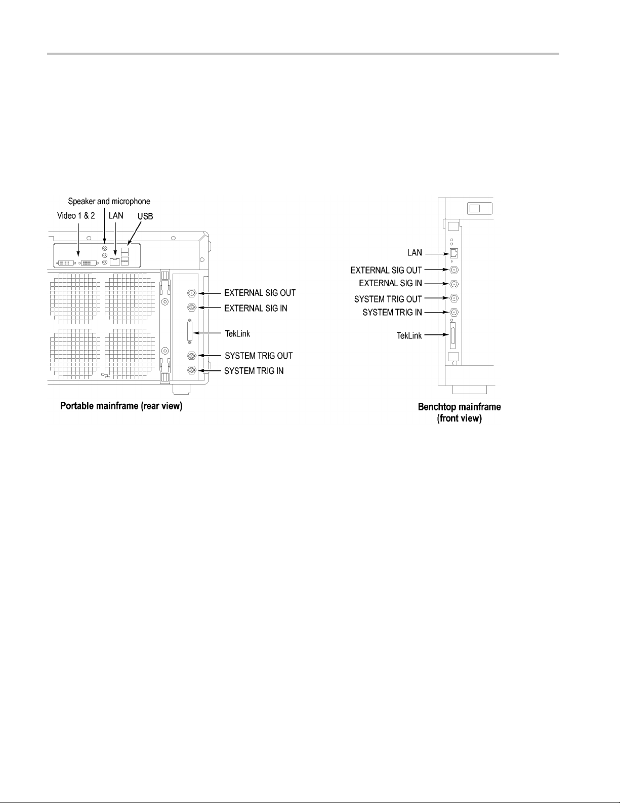
Product Overview
Connecting an Extern a l
Display
There are two di
only), and Secondary (DVI-I, digital/analog out). Simulscan mode displays the
same information on the internal display and the external monitor connected to
either Primary or Secondary.
To enable Simulscan mode, or to enable/disable external monitors or make other
display changes, right click on your desktop and select Properties > Graphics
> Intel Graphics Technology.
splay ports on the TLA7012: Primary (DVI-D, digital output
e 66: TLA7000 Series external connectors
Figur
82 TLA7000 Series Logic Analyzers Installation Manual
 Loading...