

Teknatool Nova Viking Series, Nova 83701, Nova 83700, Nova 83703, Nova 83702 Operation Manual
...Page 1
123-0719-018
OPERATION MANUA
L
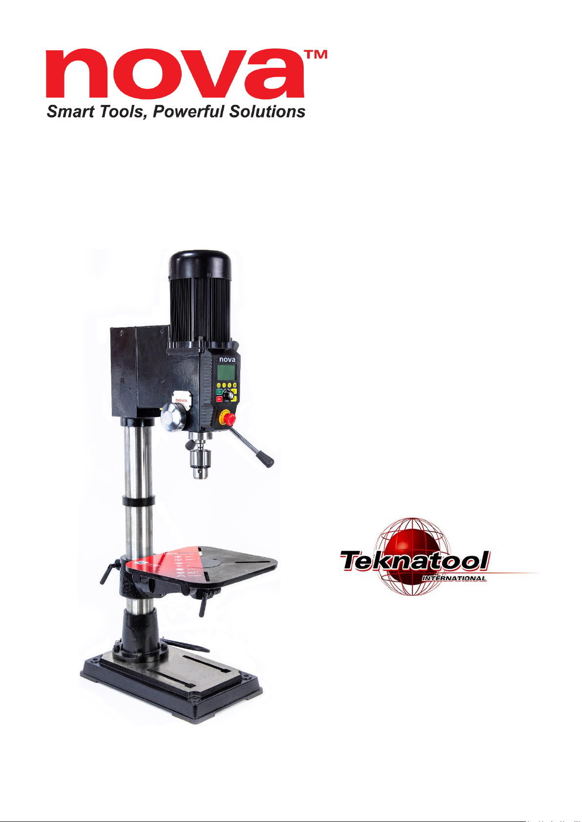
Viking DVR 16”
Benchtop Drill Press
™
Publication: 123-0719-018
Date: 11 July 2019
Models:
83700 - USA
83701 - NZ/Australia
83702 - Canada
83703 - Europe
83704 - UK
Page 2

123-0719-018
Contact
Teknatool International Ltd
Phone: (+64) 9 477 5600
Teknatool USA
Phone: 727-954-3433
Customer Solutions
For all worldwide Inquiries, Repairs or Services (issues must be in writing)
Email: [email protected]
Or you can contact the retailer where you purchased your NOVA Viking DVR Drill Press, for the contact
details please see our website www.teknatool.com
Page 3

123-0719-018
Table of Contents
Contact .................................................................................................................................................................................... 2
Table of Contents .................................................................................................................................................................... 3
General Safety Rules ............................................................................................................................................................... 5
Additional Safety Rules for Drill Presses ................................................................................................................................. 6
NOVA DVR Viking Features ..................................................................................................................................................... 1
Drill Press Features ............................................................................................................................................................. 1
Drill Press Specifications ..................................................................................................................................................... 2
Package Contents .................................................................................................................................................................... 3
Assembling the Drill Press ....................................................................................................................................................... 4
Drill Press Body ................................................................................................................................................................... 4
Drill Chuck and Arbor .......................................................................................................................................................... 4
Drill Press Handle ................................................................................................................................................................ 5
Chuck and Arbor Assembly Attachment ............................................................................................................................. 5
Attaching the Drill Press Table ............................................................................................................................................ 6
Tilting the table ............................................................................................................................................................... 6
Attaching the Chuck Guard ................................................................................................................................................. 7
Connecting to Power ............................................................................................................................................................... 8
Ground Fault Interrupters (GFI) ...................................................................................................................................... 9
Setting up your drill press ....................................................................................................................................................... 9
Setting up your workshop environment ............................................................................................................................. 9
Drill Press Interface ............................................................................................................................................................... 10
Keypad Buttons ................................................................................................................................................................. 10
Display Icons ..................................................................................................................................................................... 10
Operating the Drill Press ....................................................................................................................................................... 12
Turning the Drill Press ON ................................................................................................................................................. 12
Basic Drill Press Functions ................................................................................................................................................. 12
Running the drill press .................................................................................................................................................. 12
Stopping the drill press ................................................................................................................................................. 13
Emergency Stop ............................................................................................................................................................ 13
Adjusting the speed ...................................................................................................................................................... 13
Changing the display mode ........................................................................................................................................... 14
Changing the measurement units ................................................................................................................................. 14
Switching between forward and reverse ...................................................................................................................... 15
Zeroing the depth ......................................................................................................................................................... 16
Page 4

123-0719-018
Using the light and lasers .............................................................................................................................................. 17
Intermediate Functions ..................................................................................................................................................... 18
Using the electronic depth stop function ..................................................................................................................... 18
Quick Set Depth Function ............................................................................................................................................. 19
Electronic Depth Stop Function .................................................................................................................................... 19
Using the Self-Start Function ........................................................................................................................................ 20
Power Spindle Hold Function ........................................................................................................................................ 21
Advanced Functions .......................................................................................................................................................... 22
Performing a Factory Reset ........................................................................................................................................... 22
Turning the sound on or off .......................................................................................................................................... 22
Changing the power bar settings .................................................................................................................................. 23
Calibrating the Height Sensor Drill Press ...................................................................................................................... 24
Unlocking the drill press speed range to 6000rpm ....................................................................................................... 24
Changing the drill press depth stop behaviour ............................................................................................................. 25
Maintaining your Drill Press .................................................................................................................................................. 26
Maintenance after each use ............................................................................................................................................. 26
Monthly maintenance ....................................................................................................................................................... 26
6month Maintenance ....................................................................................................................................................... 26
Speed Chart for Metal Drilling .............................................................................................................................................. 26
Full Speed Chart for General Materials ................................................................................................................................. 27
Firmware Update .................................................................................................................................................................. 28
Checking the firmware version ......................................................................................................................................... 28
USB Mode ......................................................................................................................................................................... 29
Troubleshooting .................................................................................................................................................................... 30
Mechanical Issue ............................................................................................................................................................... 30
Electrical Issues ................................................................................................................................................................. 32
Error Codes ....................................................................................................................................................................... 32
Teknatool Warranty .............................................................................................................................................................. 33
Viking Drill Press Headstock Breakdown .............................................................................................................................. 34
Viking Drill Press Stand and Base .......................................................................................................................................... 35
NOVA Viking Drill Press Parts List ......................................................................................................................................... 36
Chuck Guard .......................................................................................................................................................................... 39
Appendix ............................................................................................................................................................................... 40
NOVA Viking Wiring Diagram ............................................................................................................................................ 40
Using the included accessories ......................................................................................................................................... 41
Chuck Drift..................................................................................................................................................................... 41
Page 5

123-0719-018
General Safety Rules
WARNING! Failure to follow these rules may result in serious personal injury or death.
IMPORTANT: Before switching the drill press on, ALWAYS check the machine for the correct setting and
speed, as well as ensuring the Chuck Key is removed.
1. FOR YOUR OWN SAFETY, READ THE MANUAL
BEFORE OPERATING THE TOOL. Learn the machine’s
application and limitations, plus the specific hazards
particular to it.
2. ALWAYS USE SAFETY GLASSES (must be ANSI
approved) Everyday eyeglasses usually are only impact
resistant and safety glasses only protect eyes. A full-face
shield will protect the eyes and face. Also use face or dust
mask if cutting operation is dusty.
3. WEAR PROPER APPAREL. Do not wear loose clothing,
gloves, neckties, rings, bracelets or other jewelry which
may get caught in moving parts. Nonslip footwear is
recommended. Wear protective hair covering to contain
long hair.
4. USE EAR PROTECTORS. Use ear muffs for extended
period of operation. Use muffs rated to 103 DBA LEQ (8
hour).
5. DON’T USE IN DANGEROUS ENVIRONMENT. Don’t
use power tools in damp or wet locations, or expose them
to rain. Keep work area well lighted. The NOVA Viking
DVR Drill press is intended for indoor use only. Failure to
do so may void the warranty.
14. KEEP GUARDS IN PLACE and in working order.
15. USE CORRECT TOOLS. Do not use a tool or attachment to
do a job for which it was not designed.
16. USE RECOMMENDED ACCESSORIES. The use of
improper accessories may cause hazards.
17. DON’T FORCE THE TOOL. It will do the job better and be
safer at the rate for which it was designed.
18. MAINTAIN TOOLS IN TOP CONDITION. Keep tools sharp
and clean for best and safest performance. Follow
instructions for lubricating and changing accessories.
19. NEVER STAND ON TOOL. Serious injury could occur if the
tool is tipped or if the cutting tool is accidentally contacted.
20. REMOVE ADJUSTING KEYS AND WRENCHES. Form a
habit of checking to see that keys and adjusting wrenches
are removed from tool before turning it on.
21. DON’T OVERREACH. Keep proper footing and balance at
all times.
22. DIRECTION OF FEED. Feed work into a blade or cutter
against the direction of rotation of the blade or cutter only.
23. PAY ATTENTION TO WORK. Concentrate on your work. If
you become tired or frustrated, leave it for a while and rest.
24. SECURE WORK. Use clamps or a vice to hold work when
practical. Severe injury or death can occur if an object comes
free as it can become a dangerous projectile.
25. CHECK DAMAGED PARTS. Before further use of the tool,
any part that is damaged should be carefully checked to
ensure that it will operate properly and perform its intended
function. Check for alignment of moving parts, binding of
moving parts, mounting, and any other conditions that may
affect its operation. Any damaged part should be properly
repaired or replaced.
26. DRUGS, ALCOHOL, MEDICATION. Do not operate
machine while under the influence of drugs, alcohol, or any
medication.
27. DUST WARNING. The dust generated by certain woods
and wood products can be harmful to your health. Always
operate machinery in well-ventilated areas and provide
means for proper dust removal. Use wood dust collection
systems whenever possible.
28. DO NOT MODIFY OR USE DRILL PRESS FOR USES
OTHER THAN FOR WHICH IT WAS DESIGNED.
6. KEEP WORK AREA CLEAN. Cluttered areas and benches
invite accidents. Build-up of sawdust is a fire hazard.
7. KEEP CHILDREN AND VISITORS AWAY. The Nova
Viking DVR is not recommended for children and infirm
persons. Such personnel and onlookers should be kept a
safe distance from work area.
8. MAKE WORKSHOP CHILDPROOF with locks, master
switches, or by removing starter keys.
9. GROUND ALL TOOLS. If the tool is equipped with a
three-prong plug, it should be plugged into a three-hole
electrical receptacle. If an adapter is used to
accommodate a two-prong receptacle, the adapter plug
must be attached to a known ground. Never remove the
third prong.
10. MAKE SURE TOOL IS DISCONNECTED FROM POWER
SUPPLY while the motor is being mounted, connected,
or reconnected.
11. DISCONNECT TOOLS FROM WALL SOCKET before
servicing and when changing accessories such as bits,
cutters and fuses etc.
12. AVOID ACCIDENTAL STARTING. Make sure switch is in
the “Off” position before plugging in power cord.
13. NEVER LEAVE MACHINE RUNNING UNATTENDED.
Do not leave machine unless it is turned off and has come
to a complete stop
Page 6

123-0719-018
Additional Safety Rules for Drill Presses
WARNING! Failure to follow these rules may result in serious personal injury.
1. SEEK INSTRUCTION. If you are not thoroughly familiar
with the operation of drill press, obtain advice from your
supervisor, instructor, or other qualified person.
Instruction from a qualified person is strongly
recommended.
2. DO NOT OPERATE DRILL PRESS until it is completely
assembled and installed. Follow instructions and
recommendations.
3. FOLLOW ELECTRICAL CODES. Make sure wiring codes
and recommended electrical connections are followed
and that the machine is properly grounded.
4. WHEN REPLACING THE FUSE (on relevant models),
completely isolate power when removing the fuse. It is
imperative the plug is removed from the power supply
before the fuse is removed. Replace fuse cap before
reconnecting to power.
5. DO NOT OPEN THE SWITCH AND REAR COVERS.
Components can carry dangerous voltages even when
isolated from mains power.
6. KEEP WORK AREA CLEAN. Do not turn the drill press
on before clearing the drill press of all objects (tools,
scraps of wood, etc.). Keep the nearby area and floor clear
of debris.
7. CHECK SET-UP with spindle off. Examine the set-up
carefully and rotate the work piece by hand to check
clearance and check speed is correctly selected before
turning on spindle.
8. DO NOT MAKE ADJUSTMENTS when the drill press
spindle is turning. Make all adjustments with power OFF.
9. TIGHTEN ALL CLAMP HANDLES on the drill press before
operating drill press.
10. ALWAYS CHECK CORRECT SPEED IS SELECTED
BEFORE SWITCHING ON DRILL PRESS.
11. OPERATE AT RECOMMENDED SPEED. Always operate
the drill press at the recommended speeds. Consult the
built-in speed chart on the drill press for suggested
speeds.
12. DO NOT OPERATE DRILL PRESS IF DAMAGED OR
FAULTY. If any part of your drill press is missing, damaged
or broken, in any way, or any electrical component fails, shut
off the drill press and disconnect the drill press from the
power supply. Replace missing, damaged, or failed parts
before resuming operation.
13. ADDITIONAL SAFETY INFORMATION regarding the safe
and proper operation of this product is available from the
National Safety Council, 444 N. Michigan Avenue, Chicago,
IL 60611 in the Accident Prevention Manual of Industrial
Operations and also in the Safety Data Sheets provided by the
NSC. Also refer to the American National Standards Institute
ANSI 01.1 Safety Requirements for Woodworking Machines
and the U.S Department of Labor OSHA 1910.213 Regulation.
Page 7
1
123-0719-018
NOVA DVR Viking Features
Drill Press Features
DIRECT DRIVE POWER
AND CONSISTENT
TORQUE
1HP DVR Smart Digital Motor delivers
correct speed, and power to maintain
optimal torque direct to the drill head,
across the entire speed range. No belts
or pulleys to cause vibration or power
loss.
A belt and pulley system
absorb typically 20% of the
motor power before it even
gets to the tool. The DVR
motor delivers constant
torque no matter what the
materials
SMART
DIGITAL
MOTOR
Smart sensors interacting in a
number of ways safety, intelligence
workshop assist, and performance
BUILT IN LASER
AND LIGHT
Quickly locate centre position with
the cross haired laser– laser stays
aligned even when table is moved or
tilted, and the DVR low/no vibration
performance means laser won’t move
in operation. Two powerful LED lights
to keep your project well lit.
CAST IRON
WOODWORKING
TABLE
Maximum flexibility and options for the
user. Solid Cast Iron for maximum
stability. Woodworking design to
provide maximum clamping and
accessory options
12 2/3″ x 12 2/3″ (320mm x
320mm). Tilting and
Rotating
ELECTRONIC
VARIABLE
SPEED
Versatile for a variety of projects – from
large deep hole drilling, mortising,
through to high speed sanding.
DISPLAY
Large, easy to read display with
imperial (fractions or decimal) or metric
provides choice with that the customer
prefers to use.
Easy to switch between modes.
FORWARD
AND REVERSE
For LH drill bits, gives the owner more
flexibility for projects.
ELECTRONIC
DEPTH STOP
Quickly and accurately automatically
stops to the precise depth you program
for your project.
Page 8

2
123-0719-018
SELF-START
Enables a one-handed drilling
operation by automatically turning on
and off.
SPLIT MOTOR
(EXPOSED)
Easy access to motor. Much easier to
get serviced for both customers and
dealers.
BRAKING
E-stop
Drill Press Specifications
Drill Press Physical Specifications
Swing
16” (406.4mm)
Stroke
4.5” (114.3mm)
Spindle to Table
12 2/3” (321.73mm)
Spindle to Base
22 2/3” (575.73mm)
Drill Chuck
5/8” (2- 15.87mm)
Spindle Taper
2MT
Quill Diameter
60mm
Table Dimension
320 x 320mm
Base Dimension
468.7 x 270 x 55mm
Motor Specifications
Motor Type
DVR Direct Drive Smart Motor
Motor power output
1HP (0.75KW)
Maximum Speed
3000 RPM (6000 RPM when unlocked)
Input voltage
110V ~ 220V
Input Frequency
50/60 Hz
Input Current
15A (max)
Page 9

3
123-0719-018
Package Contents
Item Number
Description
SKU
1
Viking Drill Press Body
8379001~8379008
2
Drill Press Base
8379025
3
Drill Press Table
8379022
4
Table Insert
8379024
5
Chuck Drift
8379067
6
Chuck Key
8379069
7
Drill Press Chuck
8379068
8
Chuck Arbor
8379019
9
Drill Press Handle (x3)
8379044
10
Table Arm Locking Handle (x2)
8379064
11
Table arm handle
8379028
12
Open end wrench
8379066
13
USB A-A cable
8379059
14
Chuck Guard Assembly
8379009
15
Chuck Key Holder
8379102
16
Allen Key Set
AK3, AK4, AK5
Note: The Chuck Guard Assembly is only included as standard for the EU model
Page 10
4
123-0719-018
Assembling the Drill Press
Drill Press Body
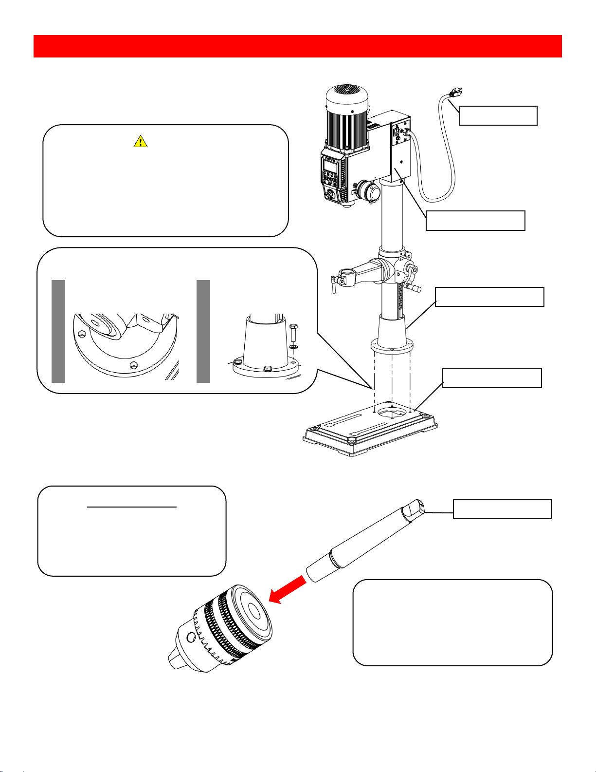
The NOVA Viking drill press come with its headstock
preassembled with its main column.
Drill Chuck and Arbor
Caution
The headstock assembly can be
heavy and it is a subject to tip over.
It is recommended to have at
least 2 people when assembling
the drill press.
Drill press headstock
Power Cable
Drill press base
Attaching the drill press base
1. Align the thread holes
on the drill press base
and column base
2. Bolt the bases
together with the M10
bolt
Drill press column base
Before assembling
Wipe down all surfaces which makes
contact with other parts free of any dusts
or lubricants.
• Both long and short side of Arbor
• Tapered hole of the chuck
Arbor tongue
Insert the short end of the Arbor into the
drill chuck.
Secure the Arbor into the chuck by lightly
tapping the Arbor tongue with a rubber
mullet.
Page 11

5
123-0719-018
Drill Press Handle
Chuck and Arbor Assembly Attachment
Screw drill press handles into the drill
press pinion shaft
Insert the arbor into the drill press
quill.
Note:
Make sure the arbor tongue is
facing the correct direction.
If the arbor is installed correctly,
the arbor should stay in the drill
press quill.
Give the chuck a few sharp taps
with a rubber mullet
Few sharp taps
with a rubber
mullet
Page 12
6
123-0719-018
Attaching the Drill Press Table
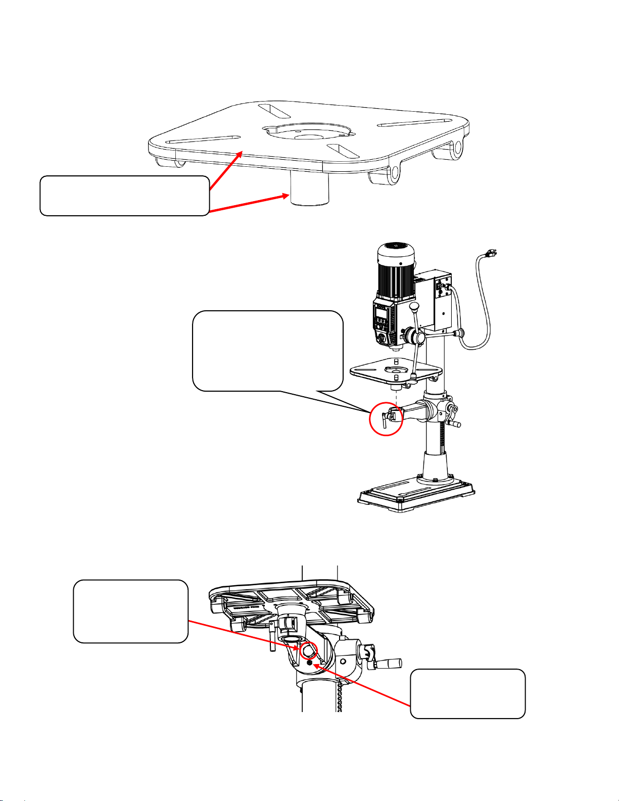
Take the drill press table out from the packaging and inspect all surfaces for and defects (i.e. Stains, rusts,
fractures, scratches) on the machined cylindrical part of the table.
Insert the drill press table into the table arm.
Loosen the table arm lock if necessary.
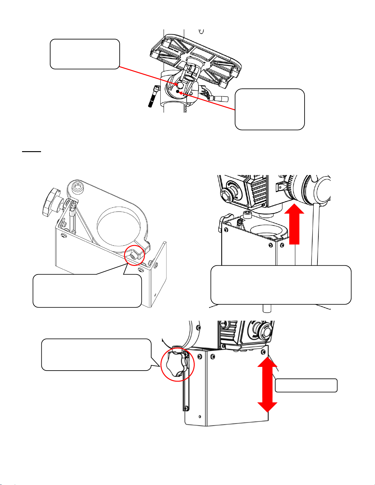
Tilting the table
Loosen the main table bolt with a 24mm wrench and loosen the smaller grub screw with <Allen Key>.
Surfaces to check for cracks,
porosities and any defects
This handle is used to lock the
inserted table into place.
Loosen this handle if the table
cannot be inserted easily
1. Main hex bolt to
be loosened with
the included
24mm wrench
2. Grub screw to be
loosened with a
mm Allen key
Page 13
7
123-0719-018
Lock the main table bolt first and then lock the secondary grub screw to secure the table position.
Attaching the Chuck Guard
Note: Only applicable to versions containing the chuck guards at default.
Take the chuck guard out from the packaging and peel off the protective sheet adhered to the guard. Inspect
for any defects on the guard.
Make sure to have the chuck guard covering the entire chuck.
Lock the main bolt
first after the table
angle has been set
Tighten the grub
screw on the bottom
after tightening the
main bolt.
Loosen the guard locking bolt
by hand or use a 5mm Allen
wrench.
Slide the guard over the drill press quill
and lock it into place by tightening the
guard locking bolt by using a 5mm Allen
wrench.
The vertical position of the
guard can be adjusted by
loosening the knob on the side.
Slide up or down
Page 14
8
123-0719-018
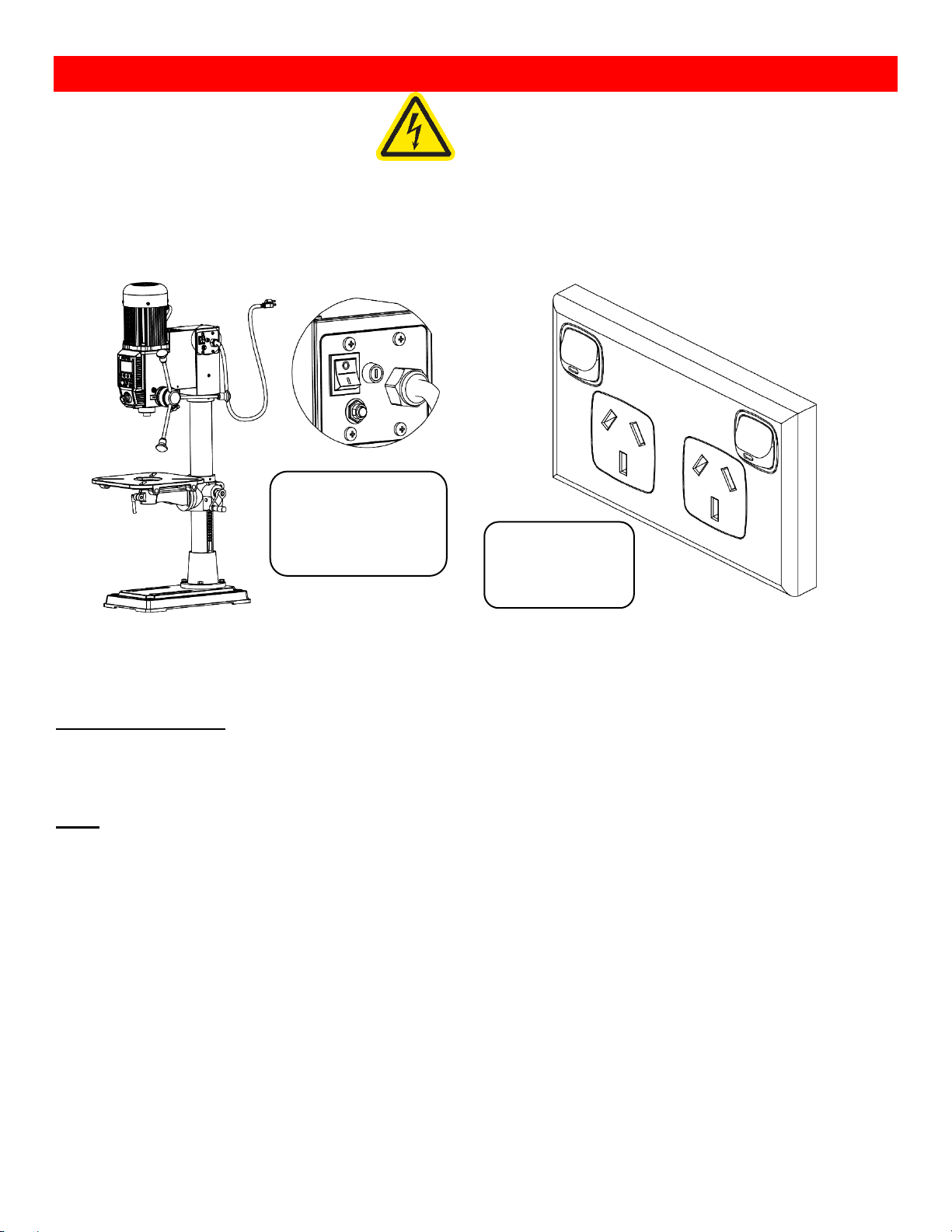
Connecting to Power
Warning!
Improper power connection may result in a risk of electrical hazard.
Make sure of the following before plugging the NOVA Viking drill press into the power source:
1. The main power switch is turned off
2. Power source is switched off
The power cord that is installed on the NOVA Viking drill press will have a three-prong plug which includes a
ground prong. The plug must be connected to a matching outlet that his properly installed and grounded in
accordance with local electrical codes.
For 115V outlet only:
A temporary adapter can be used to plug into a two-pole outlet if a three-prong outlet is unavailable in your
environment. The ground tab on the adapter must be connected to the screw on the outlet for proper
grounding. This adaptor should only be used until a qualified electrician can install a properly grounded outlet.
Note:
If an extension cable is required, make sure to check the following:
1. Extension cable gauge
2. Is the cable properly insulated?
If in any doubt, please contact your local electrician to inspect the cord according to the local electrical
standards before using it.
IMPORTANT:
A surge protection device must be used when using the drill press.
A surge protection device must be rated to at least 15A should be used in countries where 115V are used as a
standard. In countries where 240V is used, a surge protector must be rated to either 10A or 15A.
A surge protector with Joules rating of 3900J will be suitable for DVR motors.
Make sure the “O”
side of the rocker
switch is pressed in
Turn the power
outlet switch to
the “Off” position
Page 15

9
123-0719-018
Ground Fault Interrupters (GFI)
For a GFI to be compatible with the DVR motor, it must have a leak current threshold rating of 30mA
(0.03A)
Note:
Normal household GFI will typically be rated at 5mA (0.005A) which may trigger during the operation of the
DVR motor. However, frequent tripping of the GFI will not cause any harm to the DVR motor or its control
electronics as it has a built-in protective circuit to prevent damage from frequent switching.
Setting up your drill press
Setting up your workshop environment
Your workshop should set up appropriately for you to effectively use the drill press. The workshop should be
setup with the following factors taken into consideration:
1. Drill press location
o Locate the NOVA Viking drill press close to a power source in an area with good amount of lighting.
Leave enough clearance when the drill press table is swivelled around. Other machines in the
workshop should not interfere with the movement/ operation of the drill press.
2. Lighting
o The work shop should have adequate lighting. There should be enough lighting around the drill
press not to cast shadows upon the workpiece. If possible, locate the drill press near a window. A
portable spotlight might be helpful.
3. Electrical
o The NOVA Viking drill press requires an appropriate power outlet nearby to power the motor. The
outlet wiring must meet the local electrical safety standards. If in any doubt, seek advice from an
electrician. The length of an extension cable should be reduced as must as possible.
4. Ventilation
o Workshop must have an adequate level of ventilation. The level of required ventilation depends on
the size of the workshop and the amount of work that is done within the workshop. The use of dust
collectors and filters will minimize your health risk.
Page 16
10
123-0719-018
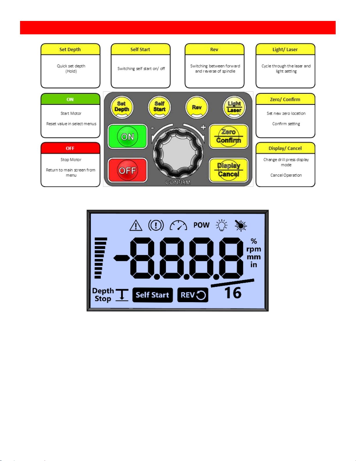
Drill Press Interface
Keypad Buttons
Display Icons
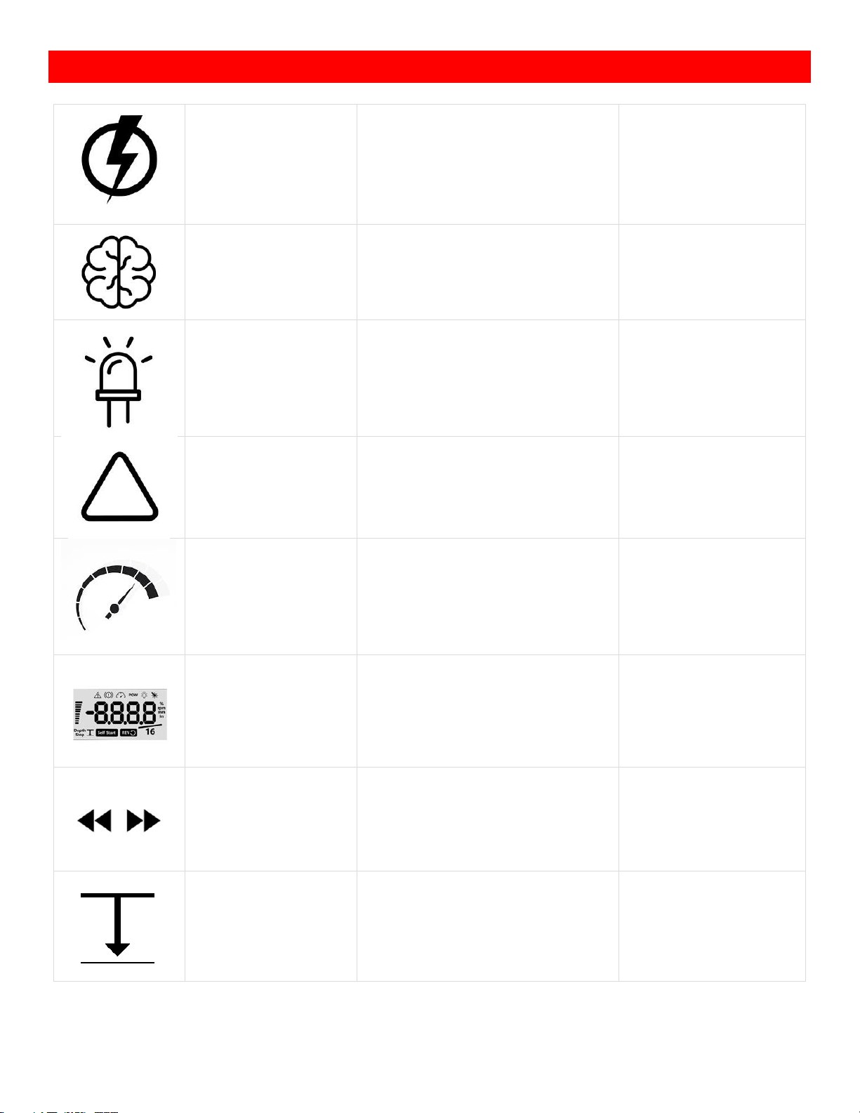
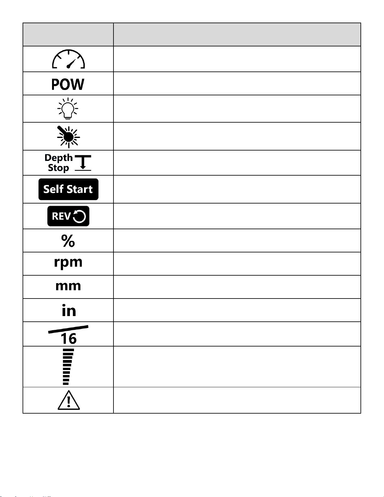
The icons are lit on the screen to indicate various information shown on the screen. The table on the next page
explains the definitions of each icons displayed on the screen.
Page 17
11
123-0719-018
Icon
Description
The number showed on the screen is spindle setting Speed
The number showed on the screen is Power output percentage
Light ON
Laser ON
The number showed on the screen is Depth of the spindle
Self-Start ON
Spindle in Rev direction
Power output percentage
Revolutions per minute
Metric
Imperial (current default)
Imperial Fraction Mode
Customizes bar graph setting (depth bar current default)
Error warning
Page 18
12
123-0719-018
Operating the Drill Press
Turning the Drill Press ON
Basic Drill Press Functions
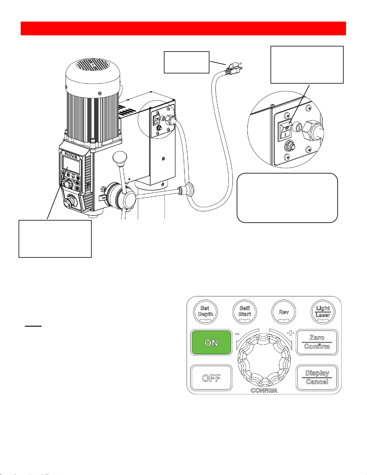
Running the drill press
Press the <ON> button on the interface panel to start
the drill press at any time.
Note:
The drill press motor will start running at the speed
that it was last set to therefore make sure to check
the set speed of the drill press before starting at all
times
Turn the main power switch to the
ON position (To the side with “I” )
after connecting the drill press to
its power source
The power button will
light up when the main
power is turned on
The LCD screen will light
up when the main power
is turned on.
Connect to
power source
Page 19
13
123-0719-018
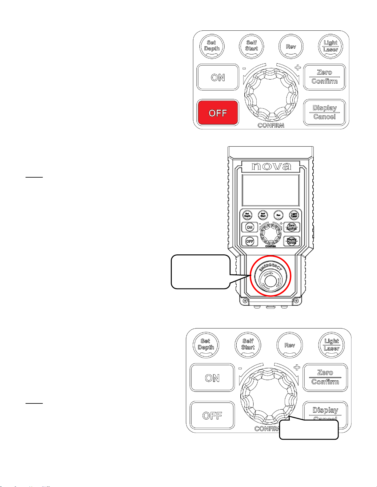
Stopping the drill press
Press the <OFF> button to stop the drill press while
it is operational
Emergency Stop
Press/ hit the emergency stop switch on the HMI
panel to bring the machine to a complete halt.
Note:
The machine cannot be restarted until the
emergency stop switch is depressed by twisting it in
the clockwise direction.
Adjusting the speed
Turn the speed knob to adjust the drill press motor
set speed at all times.
Turn the speed knob in the clockwise direction to
increase the set speed
Turn the speed knob in the anti-clockwise direction
to decrease the set speed
Note:
The drill press set speed can be adjusted at any
time while the drill press is turned on. When the set
speed knob is turned, the HMI screen will
automatically display the current set speed on the
drill press.
Emergency Stop
Switch
Turn to Adjust
Page 20
14
123-0719-018
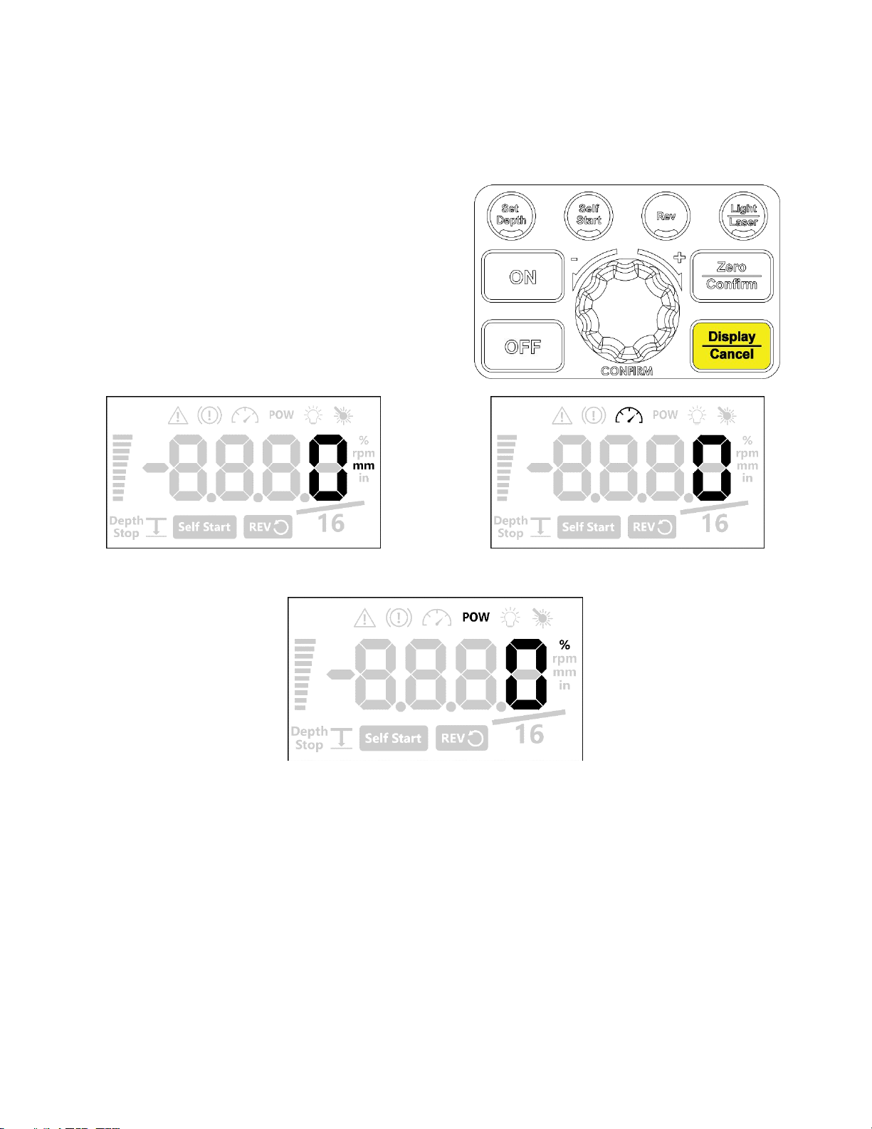
Changing the display mode
Display modes on the NOVA Viking Drill Press
There are 3 display modes available on the NOVA Viking drill press:
1. Depth
2. Speed
3. Power
Press the <Display/ Cancel> button to sequentially
cycle through each of the available display modes.
The display modes are indicated by the highlighted
icons on the HMI screen.
Depth Display Mode (In desired units)
Rotational Speed Display Mode (rpm)
Power useage display mode (%)
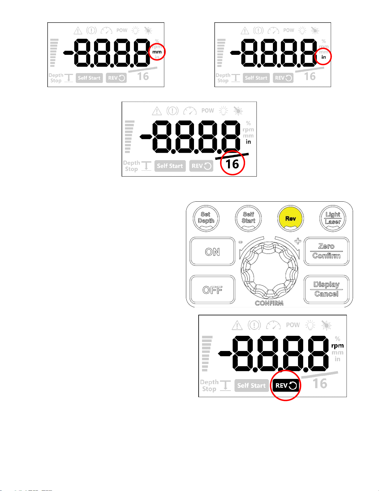
Changing the measurement units
Measurement units available on the NOVA Viking Drill Press
There are 3 types of measurement units available on the HMI screen:
1. Imperial decimal – Rounded to 0.005” (default)
2. Imperial fraction – 1/16th inch increments
3. Metric units – Millimetres
Hold down the <Display/ Cancel> button for 3 seconds unit a beeping noise is heard from the HMI.
Once the beeping noise is heard, the HMI will change the displayed measurement units
The set measurement units will be indicated on the HMI by the highlighted icons
Page 21
15
123-0719-018
Milimeter depth measurement
Imperial depth measurement
Imperial fraction depth measuermrent
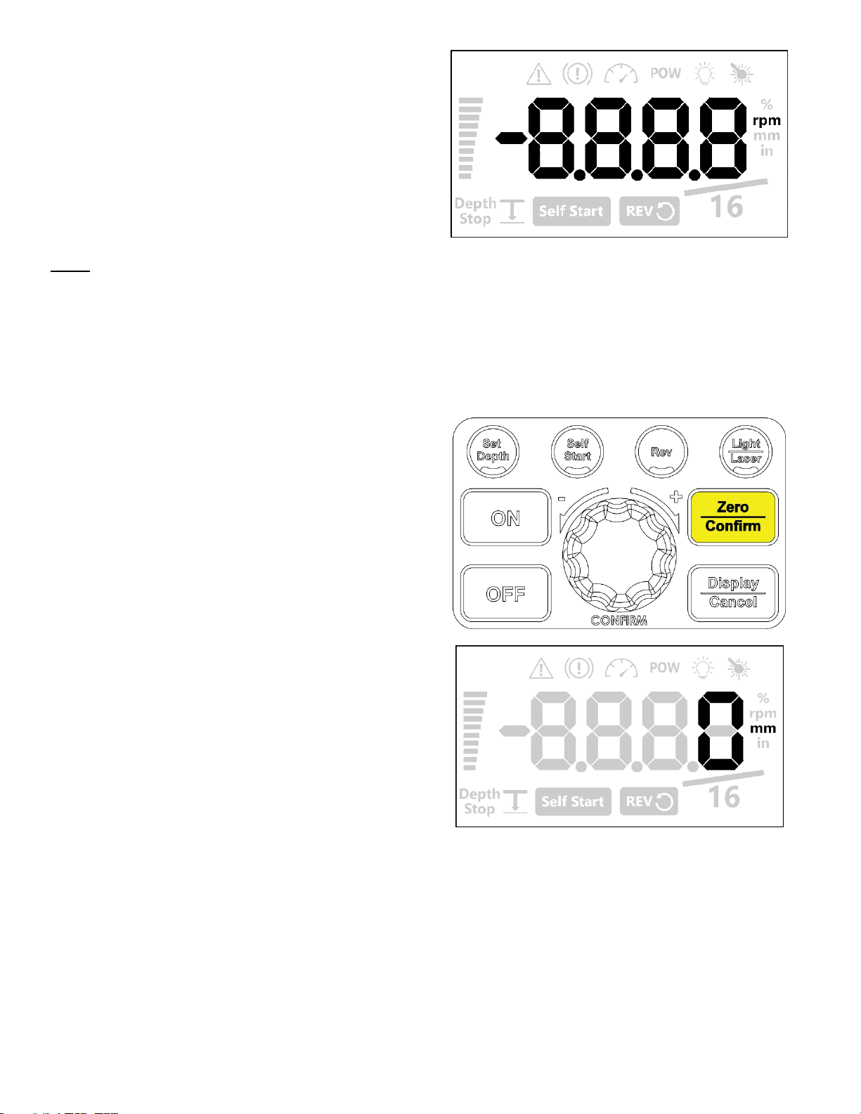
Switching between forward and reverse
Press the <Rev> button to switch between the
forward and reverse mode.
When the drill press is on reversing mode the
reverse icon will be highlighted.
Page 22
16
123-0719-018
When the drill press is on forward mode, this icon will
not be highlighted.
Note:
The forward and reverse mode cannot be switched immediately while the drill press motor is running. Drill
press must be completely stationary to switch between forward and reverse operations
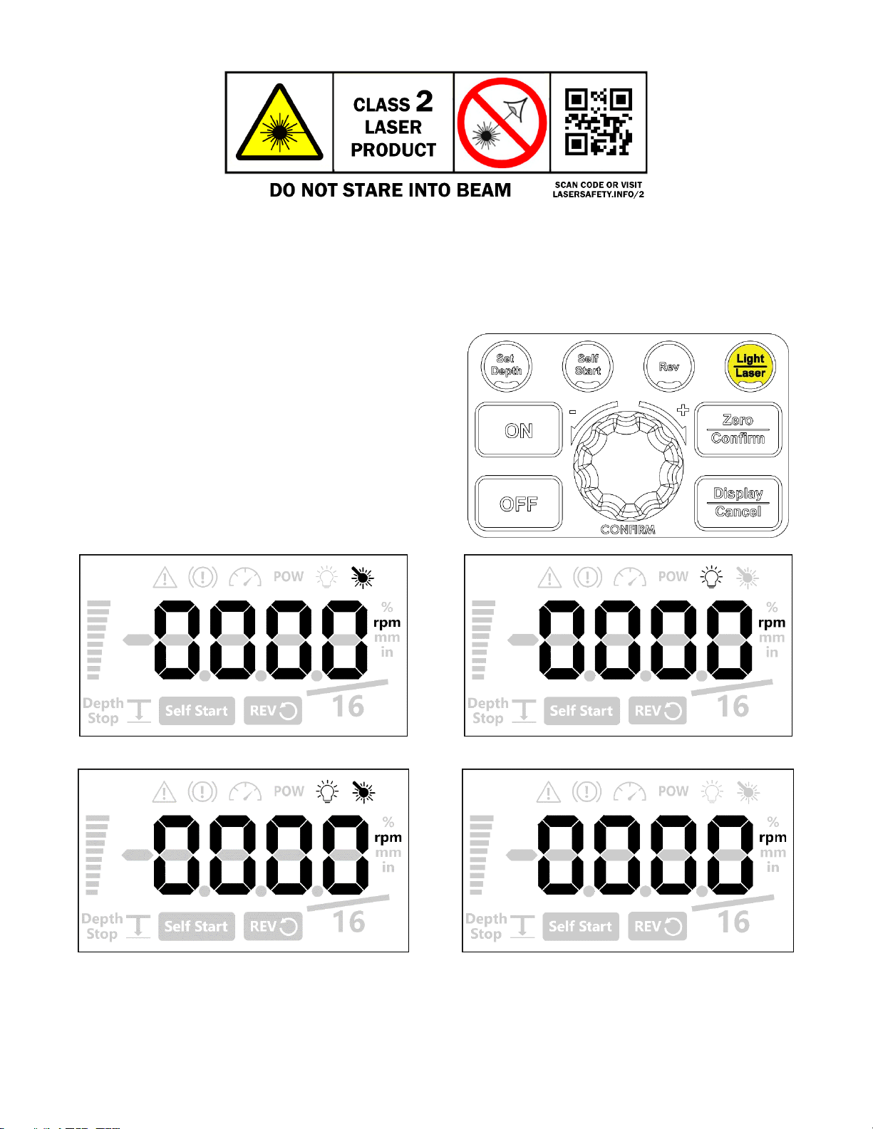
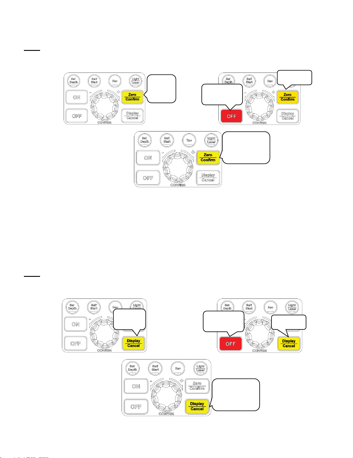
Zeroing the depth
This is also known as referencing the depth. This function will let the machine know where to start counting the
depth from.
Press the <Zero/ Confirm> button to zero the depth
reading on the drill press.
The depth read out will be set to zero at the current
extension of the quill.
E.g. If the quill is extended by 20mm and when the
depth read out is zeroed, the depth will start counting
positive from the 20mm position.
Page 23
17
123-0719-018
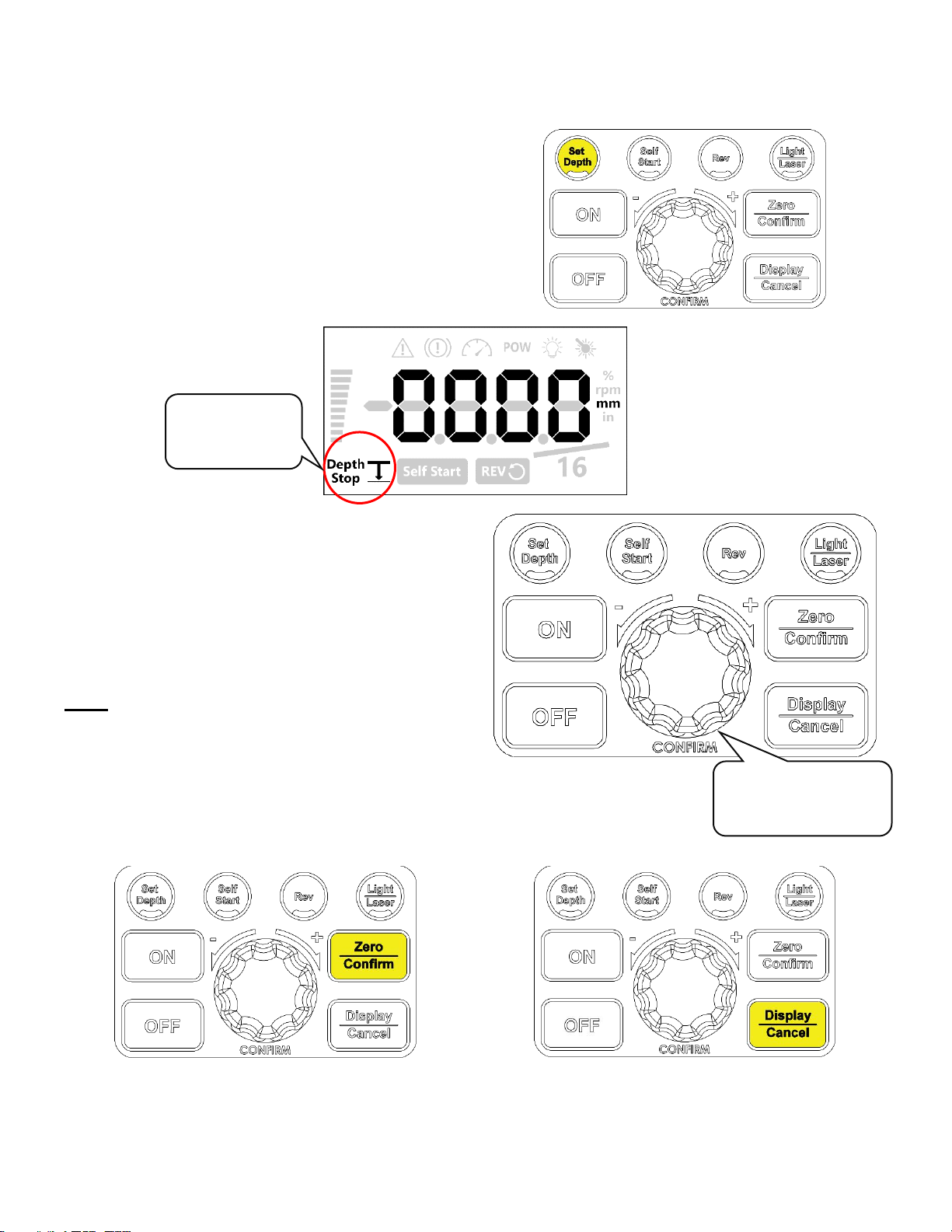
Using the light and lasers
Available laser and light modes
There are 3 laser and light modes available on the NOVA Viking drill press:
1. Both laser and light on
2. Laser on and light off
3. Laser off and light on
Press the <Light/ Laser> button to cycle through
each of the available modes on the NOVA Viking drill
press.
Each of the modes can be identified as the icons will
be highlighted to indicate which function is turned on.
Laser on
Light on
Laser and light on
Both off
The laser not accurately aligning?
Refer to <page 33> on how to adjust the laser modules
Page 24
18
123-0719-018
Intermediate Functions
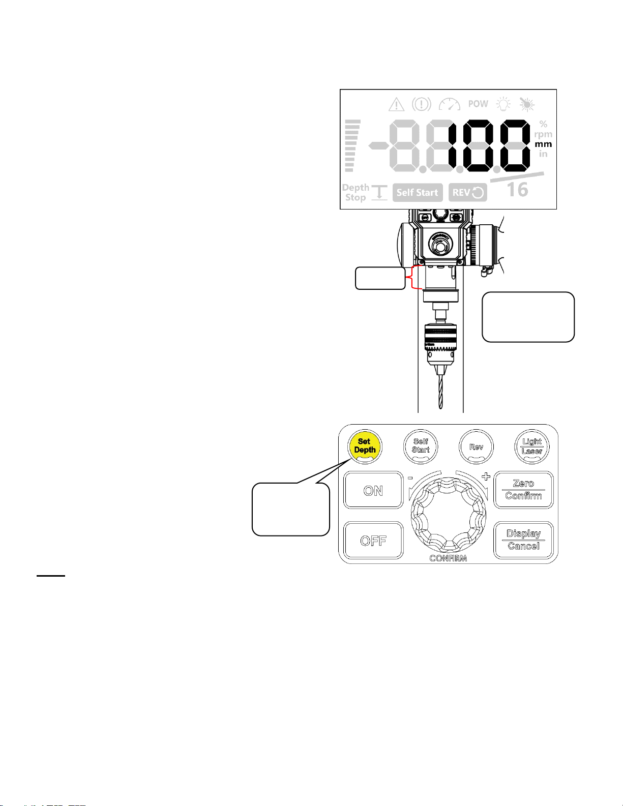
Using the electronic depth stop function
Setting the stop depth value
Press the <Set Depth> button to enter the set depth
mode of the drill press. In this mode, the Depth Stop
icon will be blinking.
Set the desired depth (measured in the selected
units) by turning the speed knob in the clockwise
direction to increase the set depth that is displayed
on the screen.
Turn the speed knob in the anti-clockwise direction
to increase the set depth that is displayed on the
screen.
Note:
Turn the speed knob for a fine adjustment.
Press and turn the speed knob for a coarse
adjustment
Once the set depth entered on the screen
Save the set depth value
Cancel and Return
Press the <Zero/ Confirm> button once the desired
depth is entered on the screen to save the set depth.
The depth stop icon will stay lit if the set depth value
is saved successfully.
Press <Display/ Cancel> button to return to the
default screen without saving.
Blinking Depth
Stop Icon
Turn the speed control
knob to set the depth
on the screen
Page 25
19
123-0719-018
Quick Set Depth Function
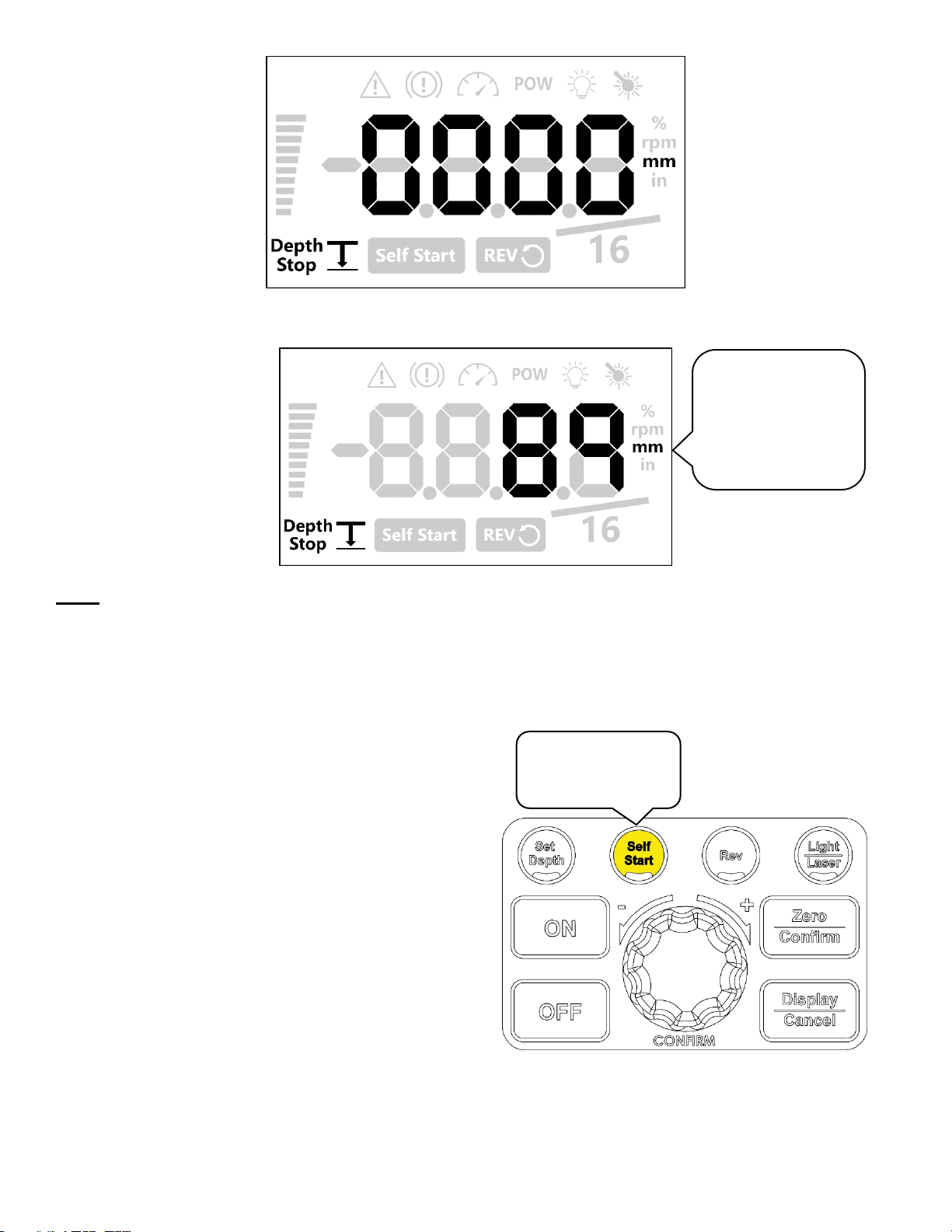
This function provides a faster method to set the depth stop value however, it may be difficult to set the exact
desired depth value with this function.
Extend the drill press quill down to the point where it
displays the desired depth value.
Press and hold the <Set Depth> button for 3
seconds while holding the quill in its position. The
HMI will beep and it will automatically save the value
that is displayed on the HMI screen as the set depth.
Note:
The quick depth stop function will save the exact value that is being shown on the screen. The value will not be
rounded when it is being saved therefore a more precise setting can be achieved quickly with this function.
Using this quick set function while the height is within 5mm (1/5”) from the top position will turn off the set depth
function.
Electronic Depth Stop Function
Once the stop depth value is specified and saved onto the machine, the electronics depth stop function is
activated.
The activation of the electronic depth stop function is indicated by the icon on the HMI screen shown below:
100mm
Extend and hold
the extended
position
Hold for 3
seconds
Page 26
20
123-0719-018
As the drill press readout approaches the set depth, the drill press screen will start to blink and HMI will start to
beep.
Note:
The screen blinking and beeping frequency will become faster as the depth read out becomes closer to the set
depth value.
Drill press will stop when the drill press depth reading reaches the set depth value. To change the drill press
behaviour when the set depth is reached can be changed refer to <page 28>
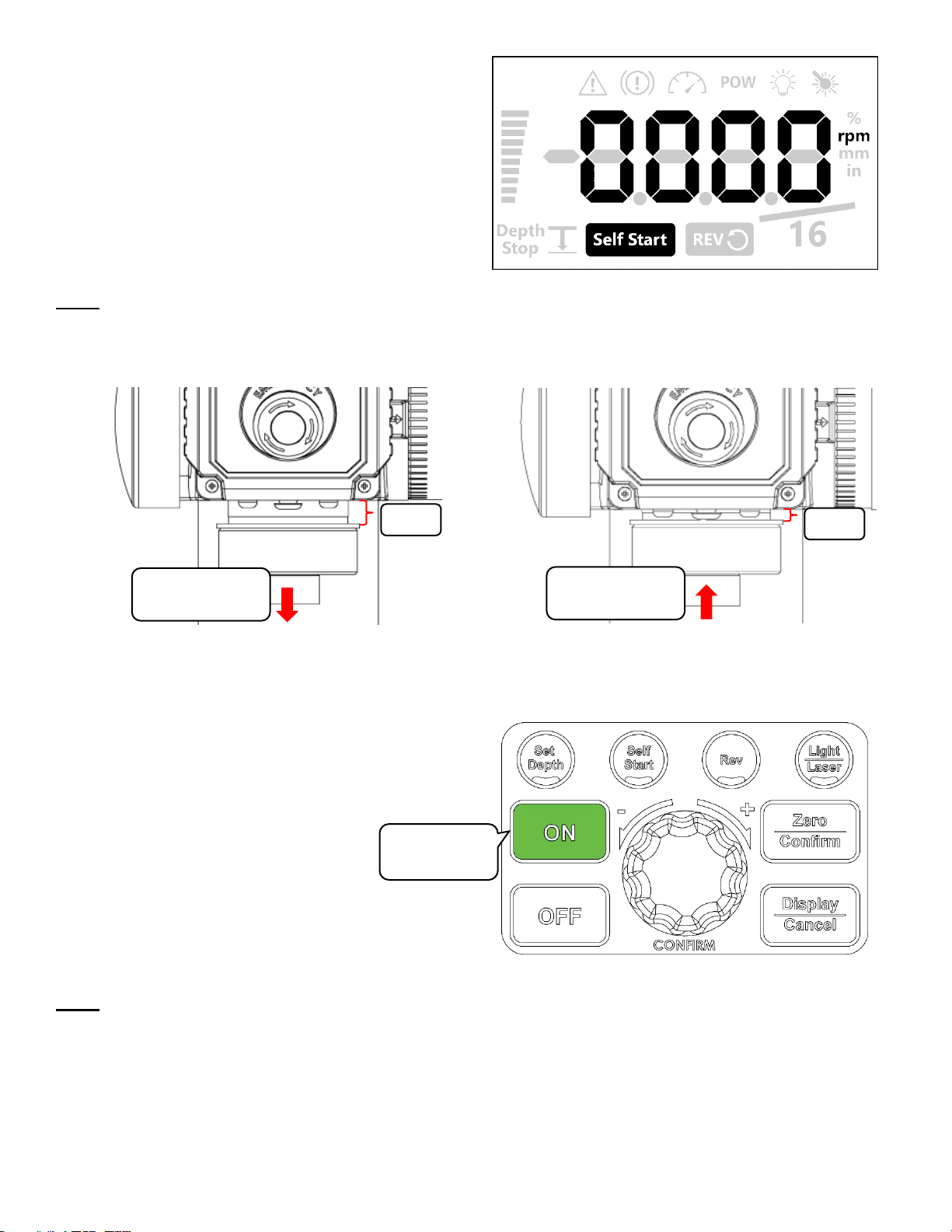
Using the Self-Start Function
Press the <Self Start> button to activate the selfstart function.
Press the <Self Start> button to deactivate the selfstart function
HMI Screen flashes
as the displayed
depth approaches
the set depth
+ Beeping Sound
Press to
activate / deactivate
Page 27
21
123-0719-018
The activation of the self-start function is indicated by
the self-start icon on the bottom of the HMI display
Note:
The self-starting depth is approximately 7mm from the top. This value is based on the absolute sensor readout
value therefore the threshold value will not be affected by any depth value offset made by the user.
The drill press will stop once the quill has been retracted back to 6mm depth.
Motor automatically start with self start function
Motor automatically stops with self start function
Power Spindle Hold Function
Press and hold the <ON> button on for 3 seconds
while the motor is on idle.
The drill press will apply 8% power on the motor to
lock the spindle in position for 30 seconds.
Note:
This function is to allow easy hand tightening of a keyless chuck
7mm
Direction of quill
travel
6mm
Direction of quill
travel
Hold for 3
seconds
Page 28
22
123-0719-018
Advanced Functions
Performing a Factory Reset
Press and hold the <Self Start> button and then press the <OFF> button.
Note:
Do not release the <Self Start> button.
Hold the <Self Start> button for another 1~2 seconds and then release.
1.
2.
3.
The factory reset will also reset the Self Start Depth threshold
Turning the sound on or off
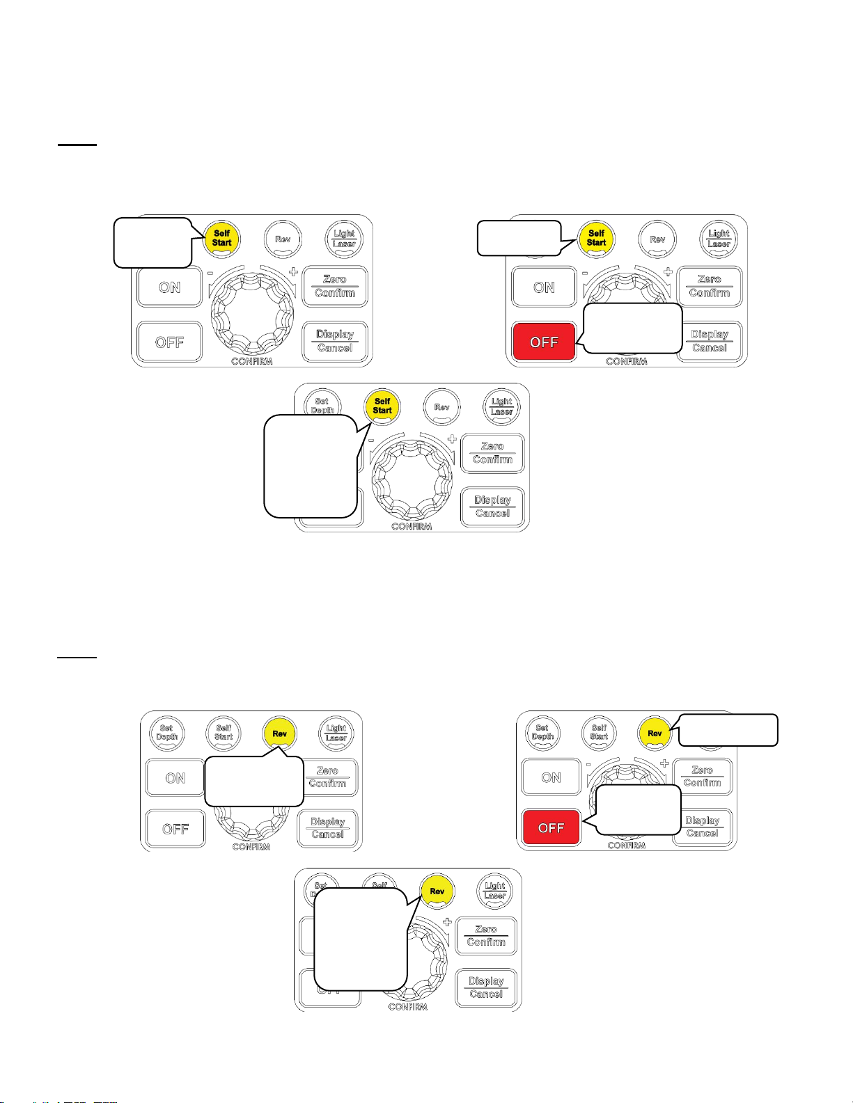
Press and hold the <Rev> button and press the <OFF> button.
Note:
Do not release the <Rev> button.
Hold the <Rev> button for another 1~2 seconds.
1.
2.
3.
Press
and hold
Keep hold
Press briefly
Keep
holding for
another
1~2
seconds
Keep
holding for
another
1~2
seconds
Press and
hold
Keep hold
Press
briefly
Page 29
23
123-0719-018
The screen will flash once and a “Sound On” or “Sound Off” message will flow from left to right on the LCD
when the command is successfully executed.
The displayed text will indicate the current sound setting of the machine.
Changing the power bar settings
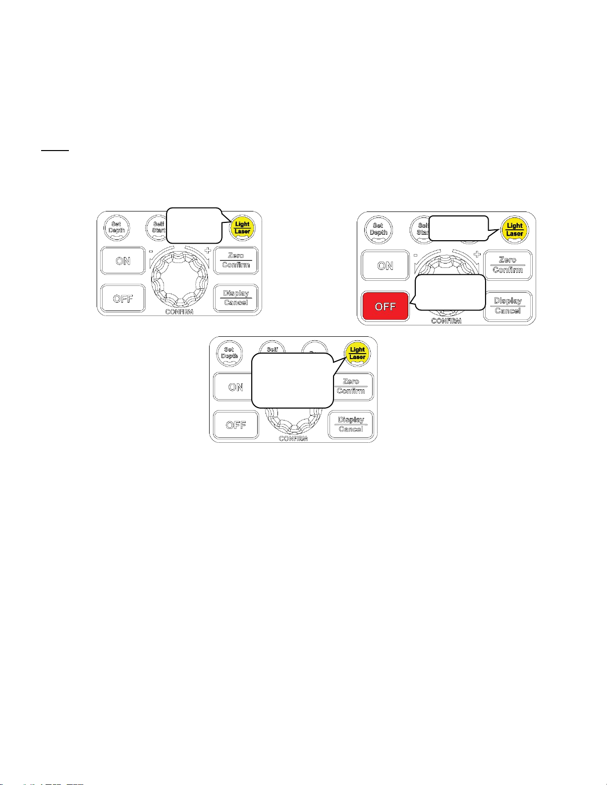
Press and hold the <Light/ Laser> button and press the <OFF> button.
Note:
Do not release the <Light/ Laser> button.
Hold the <Light/ Laser> button for another 1~2 seconds.
1.
2.
3.
The HMI screen will display one of the following texts depending on mode which the machine is set at:
1. Depth bar
2. Load bar
3. Bar off
Press
and hold
Keep hold
Press briefly
Keep holding
for another
1~2 seconds
Page 30
24
123-0719-018
Calibrating the Height Sensor Drill Press
Press and hold the <Zero/ Confirm> button and press the <OFF> button.
Note:
Do not release the <Zero> button.
Hold the <Zero/ Confirm> button for another 1~2 seconds.
1.
2.
3.
The HMI screen will display a “C” and then a certain depth on the screen.
Extend the drill press quill to the depth that is being displayed on the screen.
Press <Set Depth> button to calibrate at the specified depth.
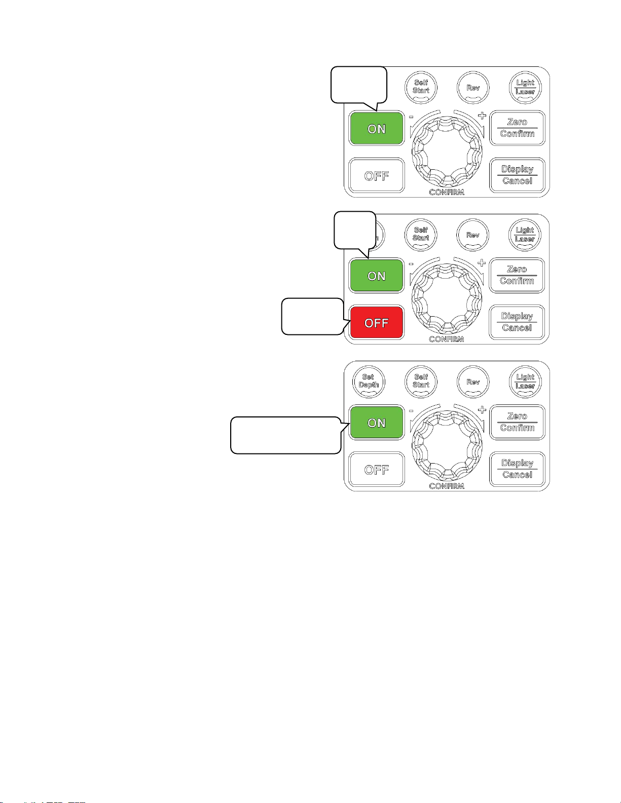
Unlocking the drill press speed range to 6000rpm
The NOVA Viking drill press can achieve a maximum operation speed of up to 6000rpm (default setting at
3000rpm). This speed is ideal for metal working purposes where it requires very fast rotation speeds
Press and hold the <Display/ Cancel> button and press the <OFF> button.
Note:
Do not release the <Display/ Cancel> button.
Hold the < Display/ Cancel> button for another 1~2 seconds.
1.
2.
3.
Press
and
hold
Keep hold
Press briefly
Keep holding
for another
1~2 seconds
Press
and hold
Keep hold
Press briefly
Keep holding
for another
1~2 seconds
Page 31
25
123-0719-018
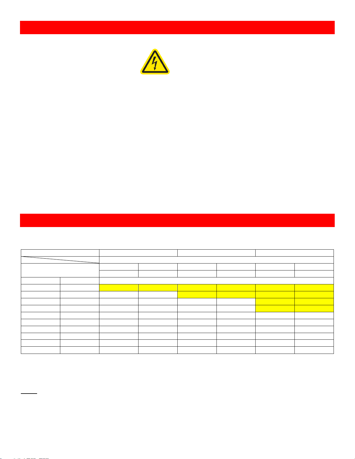
Changing the drill press depth stop behaviour
The NOVA Viking drill press has 3 different type of
behaviour when the set depth is reached during the
activation of the depth stop function:
1. Stop at set depth
2. Stop and reverse for 3 seconds (Default)
3. Stop and reverse until the quill reaches the
top.
To change this drill press behaviour:
Press and hold the <ON> button and press <OFF>.
This will sequentially cycle through the options
Press
and hold
Keep
hold
Press
briefly
Keep holding for
another 1~2 seconds
Page 32
26
123-0719-018
Maintaining your Drill Press
Regular maintenances are essential when considering the long-term use of the drill press.
Warning!
Always isolate the drill press from its power source before carrying out any
maintenance procedure
Maintenance after each use
1. Clean the work area and drill press
2. Vacuum shavings and dust from the headstock, table and base
Monthly maintenance
1. Wax coat the exposed cast iron parts with a good quality paste wax. Buff off thoroughly.
2. Check tightness of nuts and bolts
3. Clean all tapers to ensure a secure fit
6month Maintenance
1. Lubricate the gear and the rack in the table elevation mechanism, spindle splines and grooves on the
quill with a #2 tube grease
2. Lubricate the teeth of the feed shaft assembly and quill shaft with one or two drops of light weight oil.
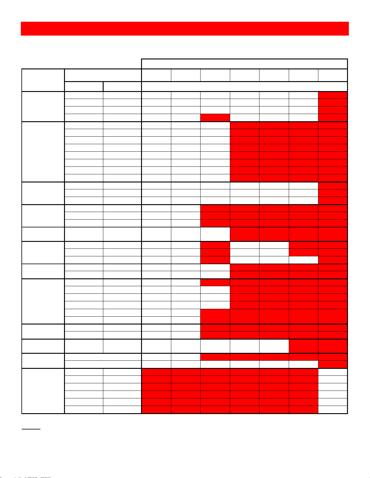
Speed Chart for Metal Drilling
The NOVA Viking DVR drill press is capable of handling both metal and wood work due to the high-power DVR
motor. Table below shows the reference speed when cutting into different metals with a twist drill bit.
Material
Cast Iron
Mild Steel
Aluminium & Copper
Feed Rate
Tool Diameter
m/min
Ft/min
m/min
Ft/min
m/min
Ft/min
24
80
30
100
60
200
mm
Inch
Cutting Speed [RPM]
2
1/16
3820
4890
4775
6000
6000
6000
3
1/8
2545
2445
3185
3055
6000
6000
5
3/16
1530
1630
1910
2035
3820
4075
6
1/4
1275
1220
1590
1530
3180
3055
8
5/16
955
980
1195
1220
2390
2445
10
3/8
765
815
955
1020
1910
2035
11
7/16
700
700
870
870
1740
1745
13
1/2
590
610
735
765
1470
1530
16
5/8
480
490
600
610
1200
1220
19
3/4
380
405
480
510
955
1020
The speeds highlighted requires the drill press to be unlocked to its high-speed drilling mode
*Refer to page24 to unlock speed for high speed metal drilling functions*
Note:
These speeds are based on High Speed Steel (HSS) cutting tools. Cutting speeds and feed rate will vary
between different tool materials.
Page 33
27
123-0719-018
Full Speed Chart for General Materials
Below is the speed chart showing the speed charts for different type of drill bits and materials.
*Table areas highlighted in red are the areas are the areas not recommended*
Material
Bit Type
Tool Diameter
Soft
Wood
Hard
Wood
Acrylic
Brass
Aluminium
Steel
Glass/ Tile
Metric [mm]
Imperial [in]
Spindle Speed [RPM]
Twist Drill
1 ~ 5
1/16 ~ 3/16
3000
3000
2500
3000
3000
3000
NA
6 ~ 10
1/4 ~ 3/8
3000
1500
2000
1200
2500
1000
NA
11 ~ 16
7/16 ~ 5/8
1500
750
1500
750
1500
600
NA
17 ~ 25
11/16 ~ 1
750
500
NA
400
1000
350
NA
Brad Point
3
1/8
1800
1200
1500
NA
NA
NA
NA 6 1/4
1800
1000
1500
NA
NA
NA
NA
10
3/8
1800
1250
1500
NA
NA
NA
NA
13
1/2
1800
1250
1000
NA
NA
NA
NA
16
5/8
1800
500
1250
NA
NA
NA
NA
19
3/4
1400
250
1250
NA
NA
NA
NA
22
7/8
1200
250
500
NA
NA
NA
NA
25
1
1000
250
250
NA
NA
NA
NA
Bullet Pilot
Point
3 ~ 5
1/8 ~ 3/16
3000
3000
3000
2000
1500
3000
NA
6 ~ 10
1/4 ~ 3/8
3000
3000
2400
1500
1000
2000
NA
13
1/2
3000
1500
1600
1500
750
1200
NA
Spade Bits
6 ~ 13
1/4 ~ 1/2
2000
1500
NA
NA
NA
NA
NA
16 ~ 25
5/8 ~ 1
1750
1500
NA
NA
NA
NA
NA
29 ~ 38
1 1/8 ~ 1 1/2
1500
2000
NA
NA
NA
NA
NA
Spade Bits with
Spur
10 ~ 25
3/8 ~ 1
2000
1800
500
NA
NA
NA
NA
Hole Saw
25 ~ 38
1 ~ 1 1/2
500
350
NA
250
250
NA
NA
41 ~ 51
1 5/8 ~ 2
500
250
NA
150
250
NA
NA
54 ~ 64
2 1/8 ~ 2 1/2
350
100
NA
150
250
100
NA
Circle Cutter
38 ~ 76
1 1/2 ~ 3
500
250
250
NA
NA
NA
NA
83 ~ 203
3 1/4 ~ 8
250
250
250
NA
NA
NA
NA
Forstner
6 ~ 10
1/4 ~ 3/8
2400
800
NA
NA
NA
NA
NA
13 ~ 16
1/2 ~ 5/8
2400
500
250
NA
NA
NA
NA
19 ~ 25
3/4 ~ 1
1500
500
250
NA
NA
NA
NA
29 ~ 32
1 1/8 ~ 1 1/4
1000
250
250
NA
NA
NA
NA
35 ~ 51
1 1/8 ~ 2
500
250
NA
NA
NA
NA
NA
54 ~ 102
2 1/8 ~ 4
250
250
NA
NA
NA
NA
NA
Power Bore
6 ~ 13
3/8 ~ 1/2
1800
500
NA
NA
NA
NA
NA
19 ~ 25
3/4 ~ 1
1800
750
NA
NA
NA
NA
NA
Shear Cutting
Countersink
6 ~ 10
1/4 ~ 3/8
1000
1000
700
850
850
NA
NA
Countersink
2 Flute
1400
1400
NA
NA
NA
NA
NA
5 Flute
1000
750
750
250
250
250
NA
Glass and Tile
3
1/8
NA
NA
NA
NA
NA
NA
750 5 3/16
NA
NA
NA
NA
NA
NA
600 6 1/4
NA
NA
NA
NA
NA
NA
500 8 5/16
NA
NA
NA
NA
NA
NA
400
10
3/8
NA
NA
NA
NA
NA
NA
350
13
1/2
NA
NA
NA
NA
NA
NA
20
Note: The speeds shown on the table is a general guide line. Drill press speed should always be determined
from the experience of the user and conditions.
Page 34
28
123-0719-018
Firmware Update
The HMI software plays an important role in the control and functionality of the NOVA Viking Drill Press. The
firmware loaded onto the HMI panel is responsible of controlling the features and performance of the drill
press.
The firmware version of the HMI can be upgraded via the included USB cable accessory and a PC with
internet access. Be sure to check www.teknatool.com periodically for firmware upgrades for your machine,
which may allow new features or software improvements that could enhance the performance of the drill press.
Checking the firmware version
Follow the instructions below to check the firmware version that is currently loaded on the drill press:
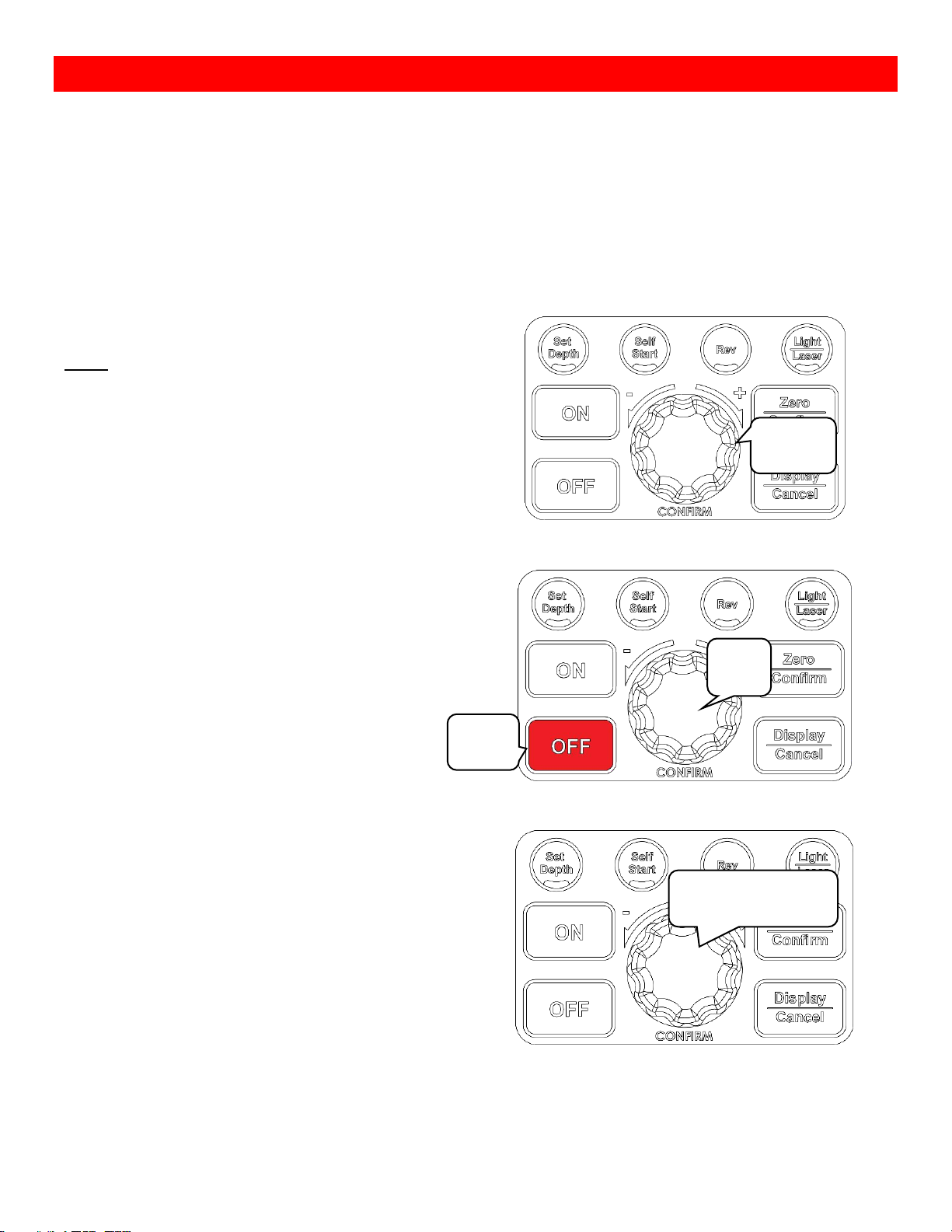
Press and hold the Speed dial and press the <OFF>
button.
Note:
Do not release the Speed dial
Hold the Speed dial for another 1~2 seconds.
Once the command has been entered successfully, the drill press will begin to display the interface firmware
version number and the main control board version number in the respective sequence.
Press
and hold
Keep
hold
Press
briefly
Keep holding for
another 1~2 seconds
Page 35
29
123-0719-018
USB Mode
When updating the HMI Firmware, HMI must be put into USB mode for it to perform the update
1. Turn off the drill press
2. Download and install the NOVA firmware update software from our website under the following URL:
https://www.teknatool.com/product/nova-voyager-firmware-upgrade/
Note: This software is only compatible with Windows Operating Systems
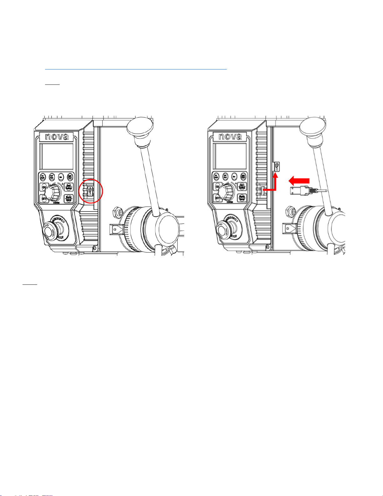
3. Remove the rubber cap from the USB port located on the right side of the HMI panel.
4. Plug the USB cable into the HMI panel and wait for approximately 5 seconds until the screen shows “USB”
Location of the USB port on the HMI Panel
Insert the long side of the included USB A-A cable
Note:
The included USB A – A cable is not a standard cable
Page 36

30
123-0719-018
Troubleshooting
Mechanical Issue
Symptom
Place to check
How to resolve
The attached tool does not run true
1. Inside the drill press spindle
2. Morse Tapered tool/ arbour
3. Chuck
4. Attached tool
Note:
The NOVA specification of the axial
runout is:
±0.02mm on Spindle Morse Taper
±0.04mm on end of arbour
±0.18mm on end of 100mm straight
rod attached to a chuck.
The solution will differ based on
where the run out is detected at:
1. Inside the drill press spindle
- The entire spindle assembly
should be replaced
2. Morse Tapered tool/ arbour
- Make sure all the contacting
surfaces are cleaned
- If the tool still has runout after
all surfaces has been
cleaned, try changing the tool
to another one.
3. Chuck
- Replace the chuck to another
4. Attached tool
- Make sure the tool is
mounted on the chuck
correctly.
Note:
When checking the cause of the
runout, always make sure to check
from the spindle.
Quill does not retract back
1. Return spring
2. Quill and quill housing
- Make sure all surfaces are
lubricated sufficiently without
excess contaminants.
3. Handle pinion gear
- Make sure all contacting
surfaces are covered with
sufficient amount of
lubricants.
Note:
Support the quill to make sure it does
not fall out from the headstock.
1. Carefully release the locking bolt
from the return spring housing
and hand tighten by rotating it in
the anti-clockwise direction. Lock
the spring housing by using the
locking bolt before releasing.
2. Extend the quill as far as possible
and apply lubricant of relatively
high viscosity. Move the quill up
and down a couple of times to
spread the lubricant.
3. Remove the handle spring and
release the locking set screws to
extract the handle from the
headstock. Apply lubricants on all
contacting surfaces and then
reassemble everything back
together.
Page 37

31
123-0719-018
Laser not aligning with the drill bit
1. Drill bit
- Make sure the drill bit is not
damaged and is mounted
onto the chuck correctly.
2. Chuck and arbour
- Check to see if there are any
misalignments when
mounting the chuck onto the
arbour or the arbour onto the
quill.
3. Laser module positioning
- If factor 1&2 are confirmed to
having no alignment issues,
the laser module position
should be adjusted.
Secure a test work piece onto the drill
press table by any method (clamp,
bolt, etc)
1. Using a small drill bit (typically
about Φ3mm) drill a hole into the
mounted work piece.
2. Turn the laser modules on.
Warning: Do not look directly
into the laser
3. Loosen the grub screws located
on the side of the headstock.
4. Adjust the angle of the laser
module so it intersects at the
marked point.
5. Tighten the grub screw back to
lock the lase modules into place.
Excessive vibration during operation
1. Workpiece mounting
- Check to see if workpiece is
securely mounted.
2. Drill press base connection
security
- Check if the drill press base
connection is secure.
3. Bench where the drill press is
mounted on.
4. Drill bit
- Check if the drill bit is blunt
or not
5. Incorrect drilling speed
1. Make sure to securely mount the
workpiece to ensure no rattling
2. Tighten all of the base connecting
screws
3. Level the bench and add
additional weights onto the bench
to dampen the vibration. If
possible, bolt the bench onto the
floor.
4. Use a sharper bit or sharpen the
dull bit
5. Refer to the speed chart
Page 38
32
123-0719-018
Electrical Issues
Symptom
Place to check
How to resolve
Drill press does not turn on
(HMI Screen not lighting up)
Firstly, unplug the drill press from its
power source and check the
following:
1. Fuse
2. Damage to the power cable
3. Open the top cover and check all
of the connection is secure on the
main board.
4. Remove the plastic interface unit
and check the ribbon cable
connection.
Note:
Make sure to securely fasten every
component back together before
connecting the drill press back into
power again.
If all connection is connected securely
and if there is no light on the HMI
screen, the main control board inside
the headstock may be dysfunctional.
Contact our customer services for
further assistance.
Error Codes
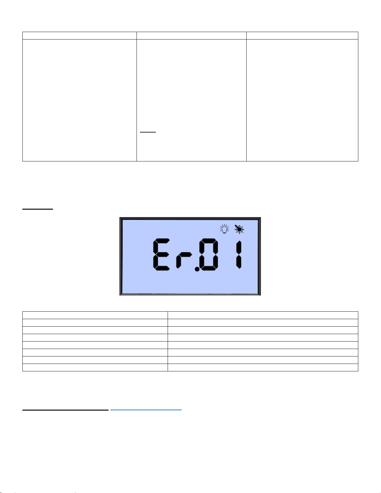
Errors are indicated on the NOVA Viking Drill Press by the HMI screen displaying “Er” followed by the error
code.
Example:
The motor is stopped when an error is displayed on the screen.
The table below shows the possible error codes which can be displayed.
Error code
Error Description
01
Over Voltage
02
Over Current
03
Motor running too fast
04
Motor not starting
05
Rotation position sensor error
06
Motor too hot
07
Main control board too hot
If an error code is displayed and drill press becomes unusable, please contact our customer services along
with the error code that is being displayed.
NOVA Customer Services: [email protected] (All enquiries must be in writing)
Page 39
33
123-0719-018
Teknatool Warranty
NOVA Limited Warranty
4499 126
th
St North | Clearwater Florida 33762
teknatool.com | 727.954.3433
This NOVA product is backed by a registered warranty from the date of purchase and only to the original purchaser. These limited
warranties are non-transferable. Under no circumstances will Teknatool International Ltd or Teknatool USA Inc. be liable for incidental,
special, indirect, and consequential damages or expenses, including loss of profits or loss of operations.
INSPECTION: Buyer shall inspect all goods within thirty (30) days of receiving product confirming all parts are in good condition and
accounted.
GUARANTEE: Teknatool International Ltd and Teknatool USA Inc. will repair or replace, at its expense and option, a NOVA product which
under normal use and intended operation, has proven to be defective in workmanship or material. Teknatool will be granted a reasonable
opportunity to verify the alleged defect by inspection and testing. Teknatool will not be responsible for any asserted defect, which has
resulted from normal wear, misuse, abuse, power surges or excess voltage fluctuation, or using in a manner or with material not consistent
with proper use, repair or alteration made by anyone other than an authorized service facility or representative.
Under these Limited Warranties, the sole liability of Teknatool is limited to repair, or at its option, replacement the applicable product or
part not in conformity with these Limited Warranties. REFUNDS ARE NOT AVAILABLE. If within the warranty period, identical materials are
unavailable at the time of repair or replacement, IN NO EVENT SHALL NOVA TEKNATOOL’S RESPONSIBILITY EXCEED THE PURCHASE PRICE
OF THE PRODUCT OR ITS REPLACEMENT AND RESERVES THE RIGHT TO USE REFURBISHED PARTS.
CONDITIONS: Prior warranty registration is not required but advised via https://www.teknatool.com/register-your-warranty/; however,
documented proof of purchase (sales receipt/invoice showing date, location, and purchase price paid) must be provided at the time of
claim. *Repairs are charged hourly. In addition, customer pays for shipping to/from and provides own shipping contain; **Warranty
Repairs: customer pays for shipping to/from and provides own shipping container; repairs are covered within warranty.
OVERSEAS CUSTOMERS: Our NOVA Distributors and agents will issue their own warranty to cover this product. Terms may vary from those
stated above; please check with your dealer. In North America, the warranty covers the Continental USA only. For Alaska, Hawaii and other
areas, warranty covers replacement of parts only and excludes transport costs.
Product
Electrical
Mechanical
All Lathes and *Accessories (except COMET)
Comet I & II
Drill Presses and *Accessories
*Excludes belts and consumables
2 years
1 year
2 years
5 years
2 years
5 years
All Chucks & Accessories
Jaws
-
-
6 years
6 years
Chisels:
-Dovetail
-Smart Chisel Handle
-
-
2 years
1 year
TO FILE A CLAIM: Contact CUSTOMER SERVICE via https://www.teknatool.com/contact-us/ or [email protected] with a full
description for claim to include pictures/videos. All claims must include the original bill of sale, the product serial number (when available),
and be filed within the applicable warranty period. Teknatool reserves the right to require defective parts be returned upon request. You
must make arrangements with Teknatool to schedule the transportation of the parts from your home to the retailer or from the retailer
to your home. A RETURN GOODS (RG) form will be sent to you via email. Items shipped to Teknatool without a RG form will be refused at
shipper’s expense. If the retailer from which you purchased the product is not able to service your product, contact Teknatool in writing
at service@teknatool.
Our policy is one of continuous improvement. We therefore reserve the right to change specification/design without notice. This warranty
is Teknatool International Ltd and Teknatool USA Inc. sole warranty whether written or verbal, whether expressed or implied by law, trade,
custom, or otherwise, whether of merchantability, fitness for purpose, or otherwise, except for remedies available to customers under
the Consumer Guarantees Act or other legislation
Page 40
34
123-0719-018
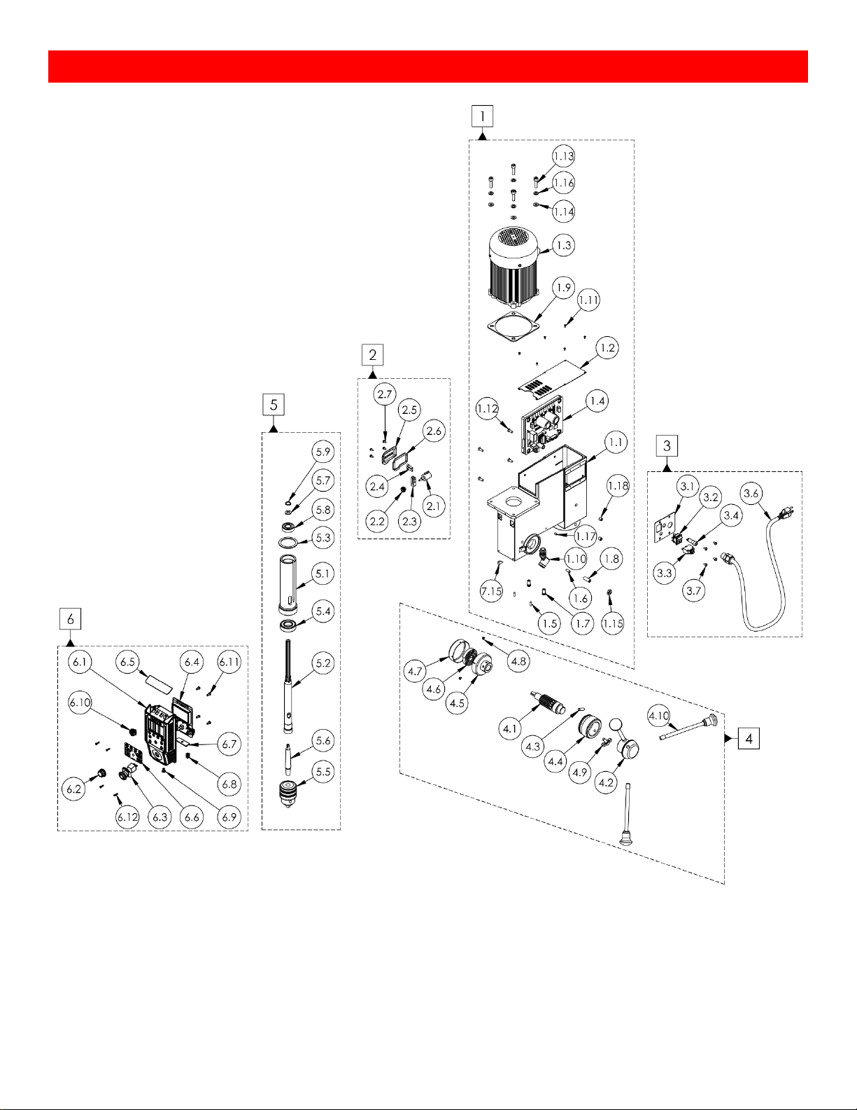
Viking Drill Press Headstock Breakdown
Page 41
35
123-0719-018
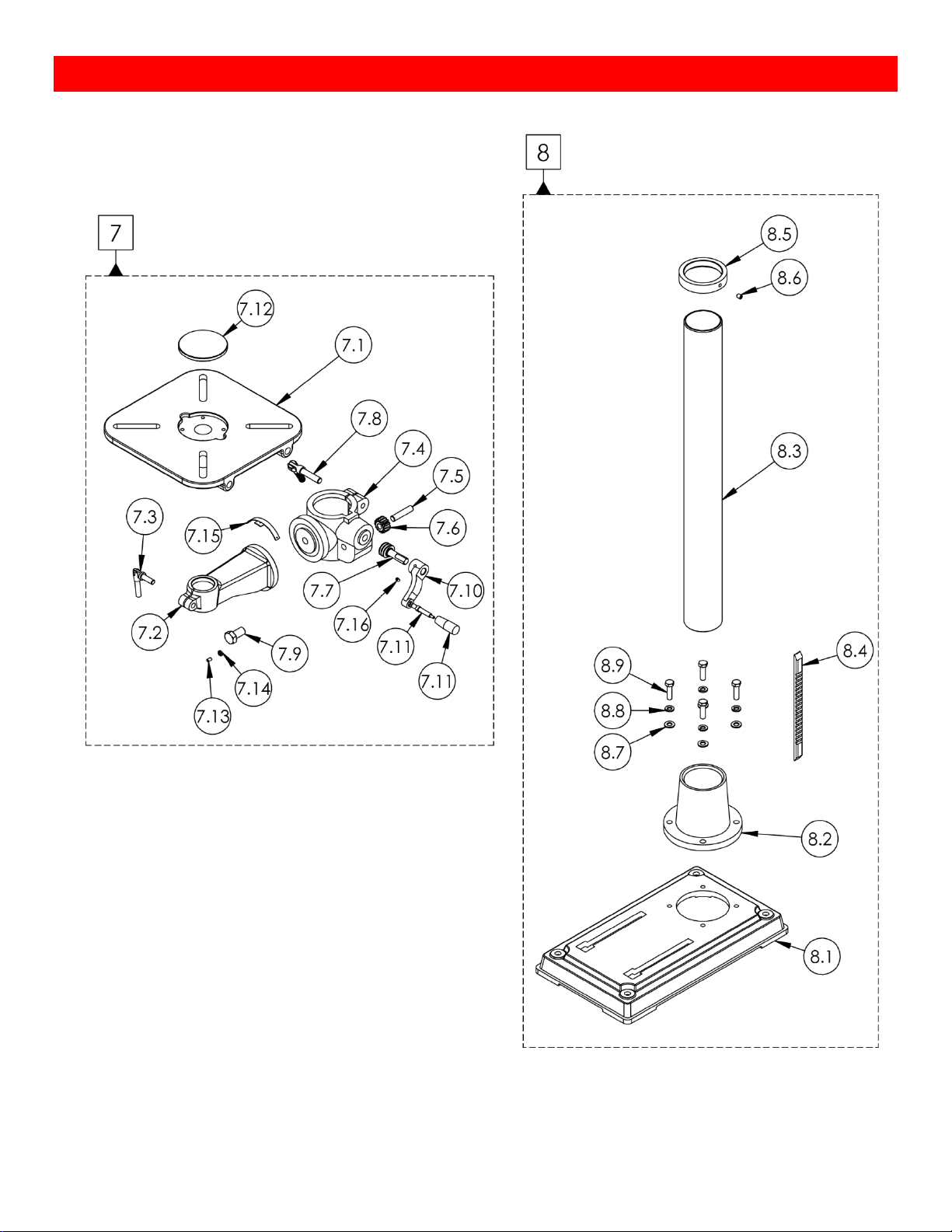
Viking Drill Press Stand and Base
Page 42
36
123-0719-018
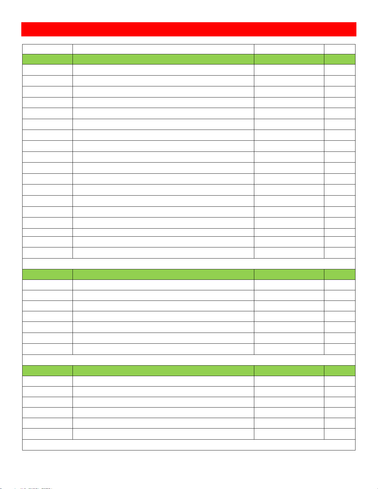
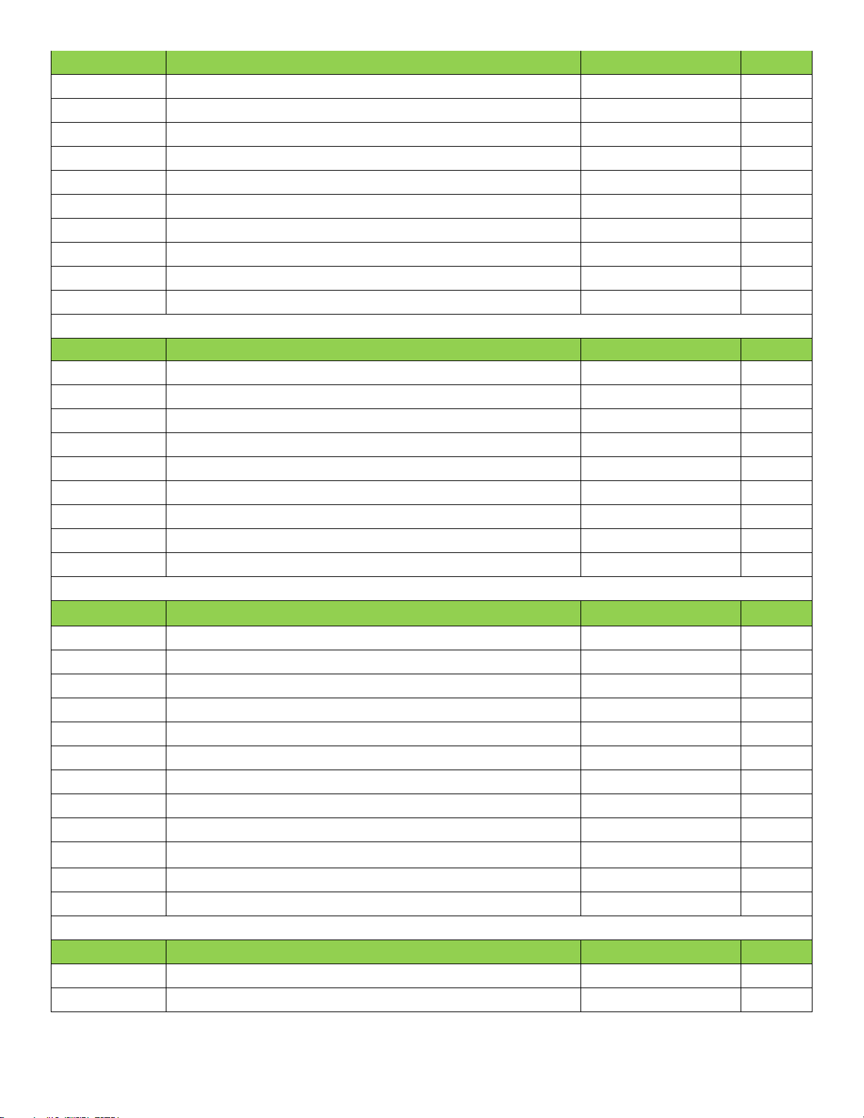
NOVA Viking Drill Press Parts List
ITEM NO.
Description
SKU
QTY.
1
Headstock Assembly
8379001
1.1
16inch Drill Press Headstock Casting
8379011
1
1.2
Sheet metal top cover
8379013
1
1.3
1HP DVR Motor
8379001
1
1.4
Main Control Board
55448
1
1.5
Spring Base Locking Screw
8379035
2
1.6
Mechanical Stop Pin
8379039
1
1.7
Laser Module
8379043
2
1.8
Quill Pin
8379045
1
1.9
Motor Rubber Gasket
8379051
1
1.10
LED Light
8379056
1
1.11
Cross Head Screws M3x6
MPB0306
6
1.12
Main Board Locking Screw
CM0616
4
1.13
Motor Mounting Bolts M8x35
C08035
4
1.14
Motor Mount Bolt Flat Washer 8mm
FW08
4
1.15
Quill Pin Nut
NH10
1
1.16
Motor Mount Bolt Spring Lock Washer 8mm
SW08
4
1.17
Laser Locking Grub Screw
SZ0508
2
1.18
Headstock Locking Grub Screw
SZ1010
2
2
Depth Sensor Assembly
8379002
2.1
Depth Sensor
8379072
1
2.2
Depth Sensor Gear
8379048
1
2.3
Depth Sensor Mounting Block
8379049
1
2.4
Depth Sensor Mounting Screw
C05020
2
2.5
Depth Sensor Cover
8379012
1
2.6
Depth Sensor Cover Gasket
8379050
1
2.7
Pan Cross Head Screw M4x8
MPB0408
4
3
Power Plate Assembly
8379003
3.1
Main Power Plate
8379017
1
3.2
Main Power Switch
8379060
1
3.3
Thermal Breaker
5668006
1
3.4
Fuse
55404
1
3.5 & 3.6
Cable Gland
8379046 & 55062
1
3.7
Pan Cross Head Screw M5x8
MPB0508
4
Page 43
37
123-0719-018
4
Handle Assembly
879004
1
4.1
Handle Pinion Shaft
8379032
1
4.2
Handle Boss
8379031
1
4.3
Handle Pinion Dowel
DW0825
1
4.4
Mechanical Stop Sleeve
8379027
1
4.5
Spring Base
8379033
1
4.6
Return Spring
8379041
1
4.7
Spring Cover
8379030
1
4.8
Return Spring Cover Screw
MPB0406
2
4.9
Mechanical Stop Lock Knob
8379040
1
4.10
Handle
8379044
3
5
4.5inch Quill and Spindle Assembly
8379005
5.1
Drill Press Quill
8379016
1
5.2
Spindle
8379015
1
5.3
Quill Rubber Space Washer
RW45
1
5.4
6205 Ball Bearing
6205LLB
1
5.5
Drill Press Chuck
8379068
1
5.6
Arbor
8379019
1
5.7
Flat Washer 17mm
FW17
1
5.8
6004 Ball Bearing
6004LLB
1
5.9
Spindle Retaining Circlip
EC15
1
6
HMI Control Panel Assembly
8379009
6.1
Drill Press HMI Plastic Panel
8379014
1
6.2
Speed Dial
8379076
1
6.3
EMS
8379047
1
6.4
Interface Board with LCD
55447
1
6.5
HMI Top Plate
8379075
1
6.6
Drill Press Keypad Membrane
8379018
1
6.7
LED Lights Board
55451
1
6.8
USB Rubber Cap
8379077
1
6.9
Plastic Rivet
8379074
1
6.10
Interlock chuck guard female connector
55526
1
6.11
HMI Board Mounting Screw
MPB0412
4
6.12
HMI Panel Mounting Screw
MPB0312
4
7
Table Assembly
8379007
7.1
Drill Press Table
8379022
1
7.2
Table Arm
8379023
1
Page 44

38
123-0719-018
7.3
Table Locking Handle
8379064
1
7.4
Table Column Bracket
8379021
1
7.5
Gear Shaft
8379065
1
7.6
Table Rack Gear
8379034
1
7.7
Table Rack Worm Gear
8379036
1
7.8
Clamp Lock Handle
8379020
1
7.9
Hex Bolt M16x30
BNMZ16030
1
7.10
Table Handle Arm
8379028
1
7.11
Handle
8379070
1
7.12
Table Insert
8379024
1
7.13
Table Arm Locking Screw
SZ0630
1
7.14
Table Arm Locking Nut M6
NH06
1
7.15
Aluminium Scale Plate Set
837078
1
7.16
Table Column Bracket Handle Grub Screw
SZ0608
1
8
Base Assembly
8379008
8.1
Drill Press Base
8379025
1
8.2
Drill Press Column Base
8379026
1
8.3
Drill Press Column
8379029
1
8.4
Rack
8379037
1
8.5
Rack Ring
8379038
1
8.6
Base Column Ring Grub Screw
SZ0810
1
8.7
Flat Washer 10mm
FW10
4
8.8
Spring Lock Washer 10mm
SW10
4
8.9
Hex Bolt M10x35
BNMZ10035
4
Page 45
39
123-0719-018
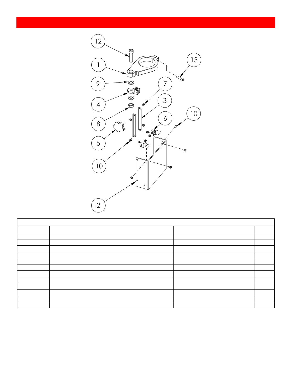
Chuck Guard
NOVA Viking Chuck Guard Assembly 8379009
ITEM NO.
Description
SKU
QTY.
1
Chuck Guard Mount
8379096
1
2
Polycarbonate Guard
8379097
1
3
Chuck Guard Slide Rack
8379098
2
4
Chuck Guard Slide Mount
8379099
1
5
Guard Slide Lock
8379100
1
6
Guard Support Plate
8379101
2
7
Nyloc Nuts M4
NN04
6
8
Nyloc Nut M10
NN10
1
9
10mm Flat Washer
FW10
2
10
Guard Fastening Screws M4x8
MPB0408
6
12
Guard Pivot Bolt M10
C10040
1
13
Guard Mount Locking Bolt M6x25
C06025
1
Page 46
40
123-0719-018
Appendix
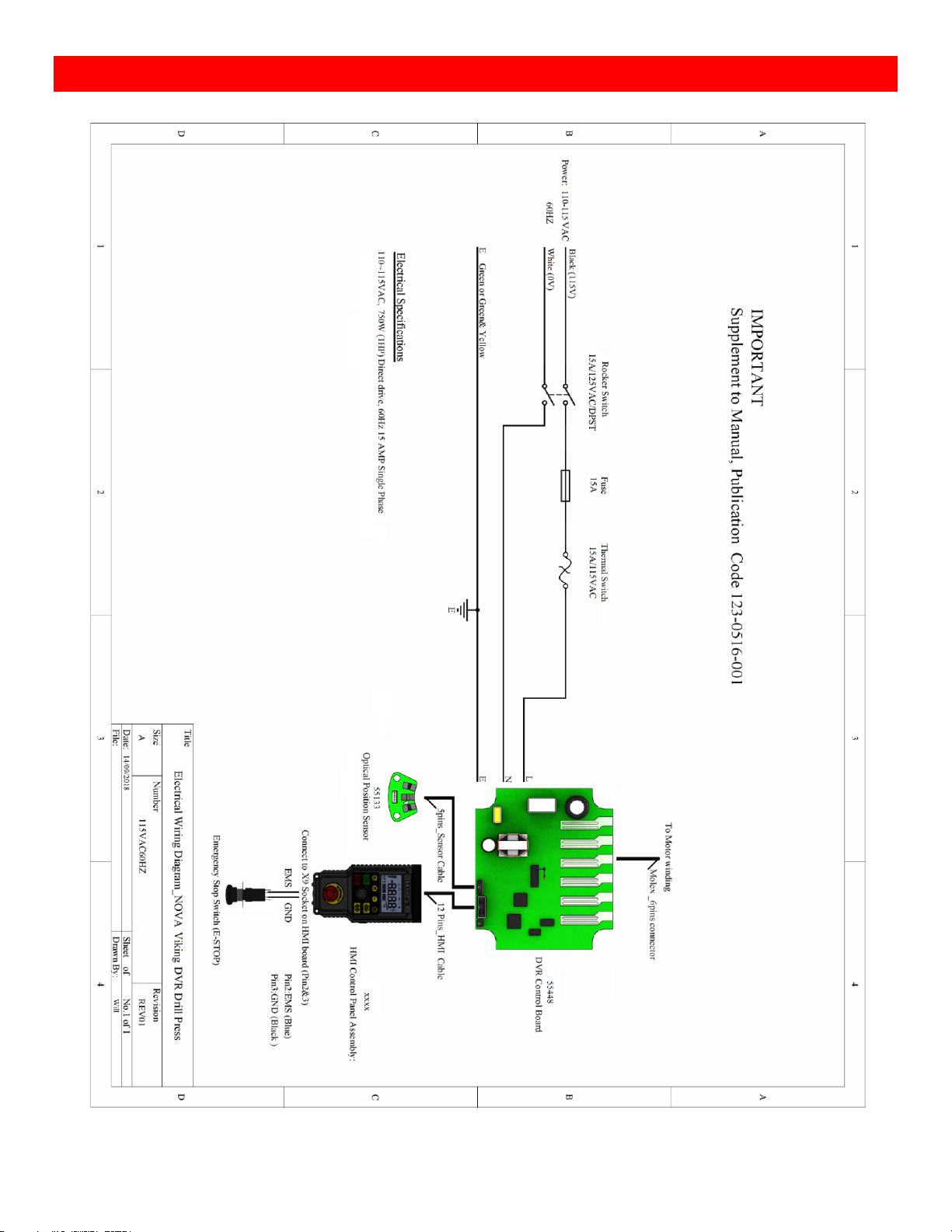
NOVA Viking Wiring Diagram
Page 47
41
123-0719-018
Using the included accessories
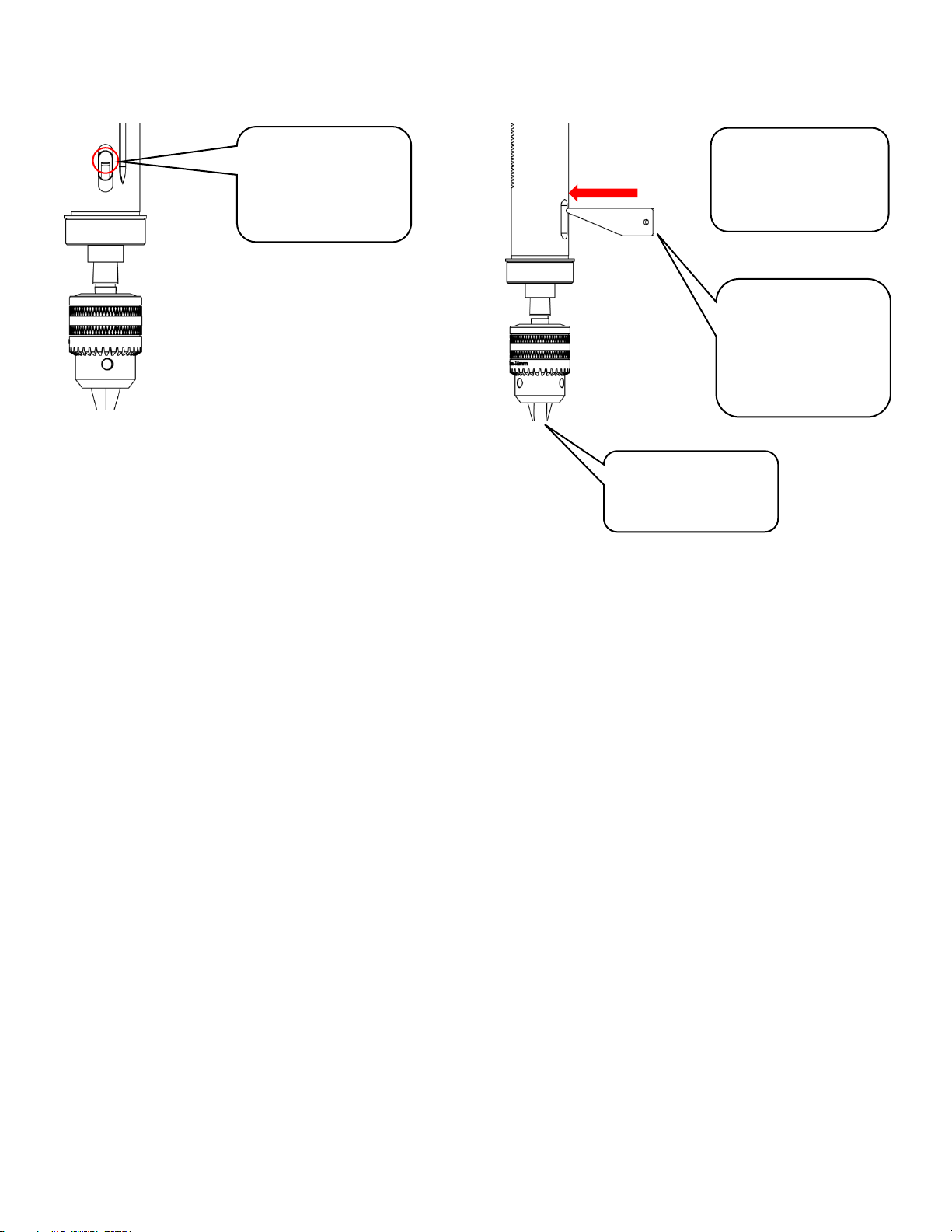
Chuck Drift
The chuck drift is used to knock out the Morse Tapered tools that are attached into the drill press quill
Extend the drill press
spindle and turn the
quill by hand until the
side holes align
Insert the chuck drift
into the aligned hole
(Taper facing the
bottom)
Strike the chuck drift
from the end with a
mullet (or any tool
equivalent) to take
out the Morse
Tapered tool
Support the chuck
from the bottom
when striking the drift
Page 48

NOVA Viking DVR 16” Benchtop Drill Press Manual
123-0719-018
© Teknatool® International 2019
All rights reserved. Teknatool® USA Inc.
11 July 2019
 Loading...