

Page 1
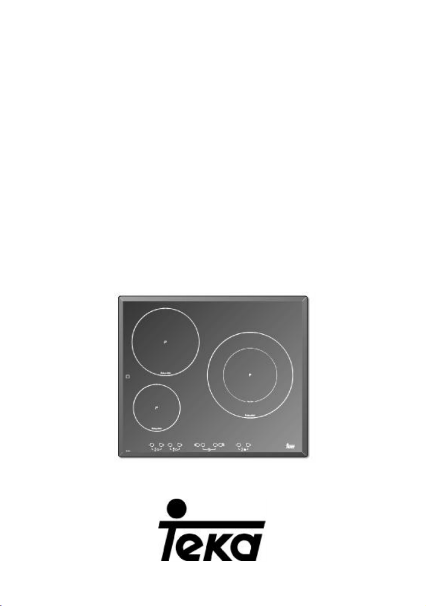
INSTALLATION INSTRUCTIONS
AND RECOMMENDATIONS FOR USE AND MAINTENANCE
INDUCTION HOBS
EINBAU-ANLEITUNG
UND EMPFEHLUNGEN FÜR GEBRAUCH UND INSTANDHALTUNG
INDUKTIONSKOCHFELD
INSTRUCTIONS POUR L’INSTALLATION
ET RECOMMANDATIONS D’UTILISATION ET D’ENTRETIEN
PLAQUES À INDUCTION
IR 631 - IT 631 - IR 641 - IT 641 - IRC 631
IR 630 - IT 630 - IR 831
Page 2

Introduction / Allgemeines / Présentation
GB
Notes about the cookware to be used with
your induction hob.
The size of the base of the cookware to be used
should be large enough to completely cover the
cooking zone drawn on the glass.
Depending on the type of cookware (material
and size), the induction zones may work with
smaller cookware.
Please remember that in order to work, the
induction elements need to be used with cookware that has a ferromagnetic base (material
attracted by a magnet).
Always use cookware with a flat, smooth base on the induction elements. Using
cookware with a deformed, concave or curved base can lead to overheating that can
damage the glass or the cookware.
Please take into account that the
cookware that you use can greatly affect the
how well the induction element works. You
may find cookware on the market that,
although marked as being suitable for induction hobs, does not work very well or is not
easily recognised by the induction element
due to the little amount or poor quality of the
ferromagnetic material that the cookware
has in its base.
DE
Hinweise zum Kochgeschirr
Der Boden des verwendeten Kochgeschirrs
sollte die gesamte Fläche der auf der
Glaskeramik gekennzeichneten Kochzone
bedecken.
Dennoch kann ebenso Kochgeschirr kleineren
Durchmessers verwendet werden, sofern
Material und Größe des Geschirrs eine
Magnetisierung erlauben.
Die Induktionszonen sind ausschließlich für
Kochgeschirr mit ferromagnetischem Boden
geeignet (magnetisierbares Material).
Der Boden des Kochgeschirrs sollte
glatt und vollkommen eben sein. Andernfalls
können Geschirr und Glaskeramik durch
Überhitzung beschädigt werden.
Induktionskochzonen hängt wesentlich von
der Art des verwendeten Kochgeschirrs ab.
Kochgeschirr für Induktionskochzonen wird
Die Leistung der
vom Hersteller entsprechend gekennzeichnet, jedoch ist dies keine Garantie dafür,
dass das Geschirr vom Kochfeld erkannt
wird oder dass die Leistung der Kochzonen
effektiv ausgenutzt werden kann.
Ausschlaggebend sind hier in jedem Fall
Qualität und Menge des im Boden des
Geschirrs verarbeiteten ferromagnetischen
Materials.
FR
Notes sur les récipients à utiliser sur votre
plan de travail à induction.
Le récipient à employer doit avoir un fond dont
la dimension de fond couvre complètement la
zone de cuisson qui figure sur la vitre.
Selon le type de récipient (matériel et dimension), les zones à induction peuvent fonctionner
avec des récipients plus petits.
Il convient de tenir compte que les plaques à
induction nécessitent pour fonctionner des récipients à fond ferromagnétique (matériau attiré
par un aimant).
Sur les plaques à induction, utilisez
toujours des récipients à fond plat et lisse.
L'emploi de récipients à fond déformé, concave ou ondulé provoque des surchauffes
qui peuvent endommager la vitre ou le propre récipient.
Il convient de tenir compte que le récipient que vous utilisez peut avoir une grande influence sur le rendement de toute plaque à induction. Il existe sur le marché des
récipients qui, malgré le fait d'être signalé
comme aptes pour l'induction, ont un rendement très faible ou des problèmes pour être
reconnus par la plaque à induction, en raison de la légère quantité ou qualité du matériel ferromagnétique qu'a le fond du récipient.
2
Page 3
1
2
1
2
3
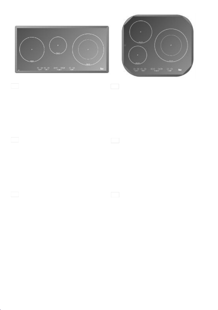
GB Model IR 641 / IT 641
1 2,100/3,000* W. induction hotplate.
2 1,600/2,300* W. induction hotplate.
3 1,100/1,800* W induction hotplate.
4 1,600/2,300* W. induction hotplate.
* Induction power with the Power function
enabled.
- Residual heat indicator (H)
- Maximum electric power: 6,400 W.
- Supply power: 230 Volts.
- Frequency: 50/60 Hertzs.
DE
Modell IR 641 / IT 641
1 Blitzkochzone 2.100/3.000* W.
2 Blitzkochzone 1.600/2.300* W.
3 Blitzkochzone 1.100/1.800* W
4 Blitzkochzone 1.600/2.300* W
* Induktionsleistung bei aktivierter
Power-Funktion
- Restwärmeanzeige (H)
- Maximale Leistung: 6.400 W
- Betriebsspannung: 230 V
- Frequenz: 50/60 Hz
Modèle IR 641 / IT 641
FR
1 Plaque radiante de 2.100/3.000* W.
2 Plaque radiante de 1.600/2.300* W.
3 Plaque radiante de 1.100/1.800* W
4 Plaque radiante de 1.600/2.300* W
* Puissance à induction avec la fonction
Power activée.
- Indicateur de chaleur résiduelle (H).
- Puissance maximum : 6.400 Watts.
- Tension d'alimentation : 230 Volts.
- Fréquence : 50/60 Hertz.
4
3
4
3
Page 4
1
1
2
3
GB Model IR 631 /IT 631
1 2,100/3,000* W. induction hotplate.
2 1,500/1,800* and 2,400/3,200* W. dou-
ble induction hotplate.
3 1,100/1,800* W induction hotplate.
* Induction power with the Power function
enabled.
- Residual heat indicator (H)
- Maximum electric power: 6,400 W.
- Supply power: 230 Volts.
- Frequency: 50/60 Hertzs.
DE
Modell IR 631 / IT 631
1 Blitzkochzone 2.100/3.000* W.
2 Blitzkochzone 1.500/1.800* und
2.400/3.200* W.
3 Blitzkochzone 1.100/1.800* W
* Induktionsleistung bei aktivierter
Power-Funktion
- Restwärmeanzeige (H)
- Maximale Leistung: 6.400 W
- Betriebsspannung: 230 V
- Frequenz: 50/60 Hz
Modèle IR 631 / IT 631
FR
1 Plaque radiante de 2.100/3.000* W.
2 Plaque radiante de 1.500/1.800* et
2.400/3.200* W.
3 Plaque radiante de 1.100/1.800* W
* Puissance à induction avec la fonction
Power activée.
- Indicateur de chaleur résiduelle (H).
- Puissance maximum : 6.400 Watts.
- Tension d'alimentation : 230 Volts.
- Fréquence : 50/60 Hertz.
2
3
4
Page 5
1
1
2
3
GB
Models IR 630 / IT 630
1 1,600/2,300* W. induction hotplate.
2 1,500/1,800* and 2,400/3,200* W. double
induction hotplate.
3 1,100/1,800* W. induction hotplate.
* Induction power with the Power function enabled.
- Residual heat indicator (H)
- Maximum electric power: 6,100 W.
- Supply power: 230 Volts.
- Frequency: 50/60 Hertzs.
DE
Modell IR 630 / IT 630
1 Induktionskochzone mit 1.600/2.300* W.
2 Induktionskochzone mit 1.500/1.800* und
2.400/3.200* W.
3 Induktionskochzone mit 1.100/1.800* W.
* Induktionsleistung bei aktivierter PowerFunktion
- Restwärmeanzeige (H)
- Maximale Induktionsleistung: 6.100 W
- Betriebsspannung: 230 V
- Frequenz: 50/60 Hz
FR
Modèles IR 630 / IT 630
1 Plaque à induction de 1.600/2.300* W.
2 Plaque à induction de 1.500/1.800* et
2.400/3.200* W.
3 Plaque à induction de 1.100/1.800* W.
* Puissance à induction avec la fonction
Power activée.
- Indicateur de chaleur résiduelle. (H)
- Puissance maximum à induction: 6.100
Watts.
- Tension d'alimentation : 230 Volts.
- Fréquence : 50/60 Hertz.
2
3
7
Page 6
1
1
GB
Modelo IR 831
1 2,100/3,000* W. induction hotplate.
2 1,100/1,800* W. induction hotplate.
3 1,500/1,800* and 2,400/3,200* W. double
induction hotplate.
* Induction power with the Power function
enabled.
- Residual heat indicator (H).
- Maximum electric power: 6,400 W.
- Supply power: 230 Volts.
- Frequency: 50/60 Hertzs.
DE
Modell IR 831
1 Induktionskochzone mit 2.100/3.000* W.
2 Induktionskochzone mit 1.100/1.800* W.
3 Induktionskochzone mit 1.500/1.800* und
2.400/3.200* W.
* Induktionsleistung bei aktivierter PowerFunktion
- Restwärmeanzeige (H)
- Maximale Induktionsleistung: 6.400 W
- Betriebsspannung: 230 V
- Frequenz: 50/60 Hz
Modèle IR 831
FR
1 Plaque à induction de 2.100/3.000* W.
2 Plaque à induction de 1.100/1.800* W.
3 Plaque à induction de 1.500/1.800* et
2.400/3.200* W.
* Puissance à induction avec la fonction
Power activée.
- Indicateur de chaleur résiduelle. (H)
- Puissance maximum à induction : 6.400
Watts.
- Tension d'alimentation : 230 Volts.
- Fréquence : 50/60 Hertz.
2
3
2
3
GB
Models IRC 631
1 1,600/2,300* W. induction hotplate.
2 1,500/1,800* and 2,400/3,200* W. double
induction hotplate.
3 1,100/1,800* W. induction hotplate.
* Induction power with the Power function enabled.
- Residual heat indicator (H)
- Maximum electric power: 6,100 W.
- Supply power: 230 Volts.
- Frequency: 50/60 Hertzs.
DE
Modell IRC 631
1 Induktionskochzone mit 1.600/2.300* W.
2 Induktionskochzone mit 1.500/1.800* und
2.400/3.200* W.
3 Induktionskochzone mit 1.100/1.800* W.
* Induktionsleistung bei aktivierter PowerFunktion
- Restwärmeanzeige (H)
- Maximale Induktionsleistung: 6.100 W
- Betriebsspannung: 230 V
- Frequenz: 50/60 Hz
FR
Modèles IRC 631
1 Plaque à induction de 1.600/2.300* W.
2 Plaque à induction de 1.500/1.800* et
2.400/3.200* W.
3 Plaque à induction de 1.100/1.800* W.
* Puissance à induction avec la fonction
Power activée.
- Indicateur de chaleur résiduelle. (H)
- Puissance maximum à induction: 6.100
Watts.
- Tension d'alimentation : 230 Volts.
- Fréquence : 50/60 Hertz.
6
Page 7
Guide to Using the Instructions Booklet
Dear customer,
We are delighted that you have put your
trust in us.
We are confident that the new hob that you
have purchased will fully satisfy your
needs.
This modern, functional and practical
model has been manufactured using topquality materials that have undergone
strict quality controls throughout the manufacturing process.
Before installing and using it, we would
ask that you read this Manual carefully and
follow the instructions closely, as this will
guarantee better results when using the
appliance.
Keep this Instruction Manual in a safe
place so that you can refer to it easily and
thus abide by the guarantee conditions.
In order to benefit from this Guarantee, it is
essential that you submit the purchase
receipt together with the Guarantee
Certificate.
You should keep the Guarantee
Certificate or, where relevant, the technical datasheet, together with the
Instruction Manual for the duration of
the useful life of the appliance. It has
important technical information about
the appliance.
Safety instructions
Before first use, you should carefully read
the installation and connection instructions.
These hob models may be installed in the
same kitchen furniture units as TEKA
brand ovens.
For your safety, installation should be
carried out by an authorised technician
and should comply with existing installation standards. Likewise, any internal work
on the hob should only be done by TEKA’s
technical staff, including the change of the
flexible supply cable of the appliance.
Please note:
When the hotplates are in operation or have recently been in operation,
some areas will be hot and can burn.
Children should be kept well away.
If the glass ceramic breaks or
cracks, the hob should immediately be
disconnected from the electric current
in order to avoid the risk of electric
shock.
Do not leave anything on the
hob’s cooking areas while it is not in
use. Avoid risk of fire.
Do not place metal objects, such
as knives, forks, spoons or lids on the
surface of the hob, as they may get very
hot.
7
Page 8
GB
Installation
INSTALLATION AND SETUP SHOULD
BE CARRIED OUT BY AN AUTHORISED
TECHNICIAN IN LINE WITH CURRENT
INSTALLATION STANDARDS.
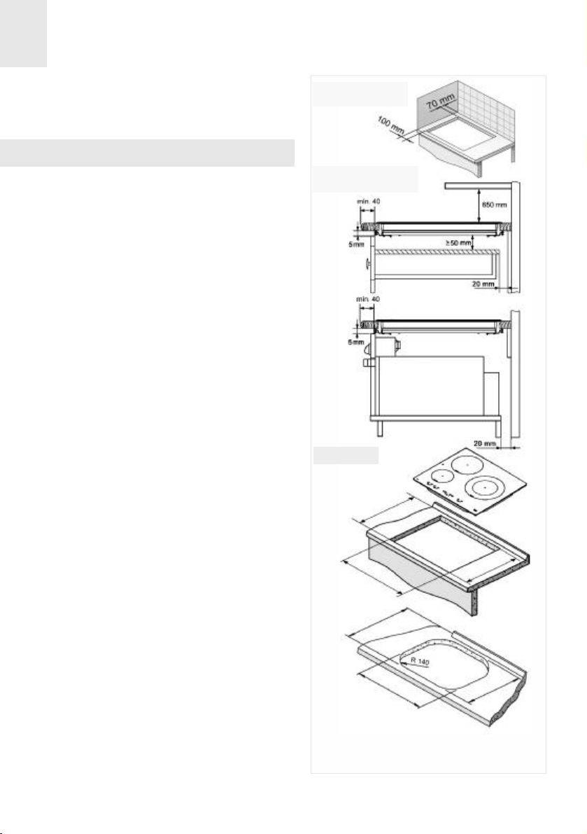
Positioning the hob
To install these models, an opening with
the dimensions shown in figure 1 will be
cut into the unit’s worktop.
The fastening system for the top is designed for furniture thicknesses of 20, 30 and
40 mm.
The minimum distance between the surface supporting the cooking pans and the
lower part of the kitchen unit or the hood
located above the hob should be 650 mm.
If the hood’s installation instructions
recommend that the gap is greater than
this, you should follow this advice.
The unit where the hob and oven will be
located will be suitably fixed.
INSTALLATION WITH CUTLERY DRAWER
Minimum distance
to wall
Minimum ventilation
distances
Fitting holes
fig. 1
DRAWER
OVEN
If you wish to install a tray drawer under
the top, place a cover or partitioning board
at least 5 cm deep from the top in order to
avoid any object placed on the drawer
obstructing the top ventilators. In this manner, we will also avoid any potential risk to
inflammable objects that may be stored in
the drawer.
INSTALLATION WITH FAN OVEN
UNDER THE HOB
The oven should be installed according to
the corresponding manual.
If a fan oven is being installed, please
remember that this hob has only been certified to work with TEKA brand ovens.
8
.
x
a
m
5
7
5
L
Model IRC 631:
.
x
a
m
5
7
5
L
The dimensions L and W are shown in the table
"Dimensions and characteristics" of the Technical
Information section.
W
W
Page 9

GB
Leave a space in the front of the cabinet so
that the hot air can ventilate properly. The
opening should be at least 5 mm high. The
longitude should be the width of the cabinet.
An opening of 20 mm should be made in
the back part of the cabinet in order to
allow cold air to enter (see figure 1).
Warnings:
To secure the hob to the cabinet, four brackets should be fastened to the existing holes
on the bottom part of the casing (two in the
front and two in the back). There are two
possibilities of where the brackets may be
placed, just as is shown in figure 2.
The model IR 831 includes ten brackets instead of four (three in the front, three in the
rear and two on each side).
When hobs are handled before
being installed, care should be taken in
case there is any protruding part or
sharp edge which could cause injury.
When installing units or appliances above the hob, the hob should be
protected by a board so that the glass
cannot be damaged by accidental
blows or heavy weights.
The glues used in manufacturing
the kitchen unit and in the adhesive on
the decorative laminate of the worktop
surface should be made to tolerate temperatures of up to 100ºC.
TEKA assumes no responsibility
for any malfunction or damage caused
by faulty installation.
PLEASE REMEMBER THAT THE GUARANTEE DOES NOT COVER THE
GLASS IF IT SUFFERS A VIOLENT
BLOW OR IF IT IS USED IMPROPERLY.
Fastering the hob
When the gap has been properly sized, the
sealing washer should be put on the lower
face of the glass. Silicone should not be
applied between the glass and the unit
worktop because if it becomes necessary to remove the hob from its position,
the glass could break when trying to
detach it.
Sealing washer
Sealing washer
fig. 2
Depending on the thickness of the cabinet, it
may be necessary to use the self tapping
screws that are provided as compliments for
securing; insert them in the circular holes of
the bracket. The thread of this hole will be
made when the screw is inserted inside of it.
The thread should be made before faste ning the bracket to the hob.
Connecting the electricity
The electric connection is made via an
omnipolar switch or plug where accessible,
which is suitable for the intensity to be tolerated and which has a minimum gap of 3
mm between its contacts, which will ensure
disconnection in case of emergency or
when cleaning the hob.
The connection should include correct earthing, in compliance with current norms.
If the flexible supply cable fitted to these
appliances ever needs to be changed, it
9
Page 10

GB
should be replaced by TEKA’s official service.
The input cable should not be in contact
either with the body of the hob or with the
body of the oven, if the oven is installed in
the same unit.
When using the hob for the first
time, please take care not to have
powerful halogen lights, like those of a
hood, shining over the sensor button
area of the hob. These lights may interfere with the starting of the system.
10
Page 11
GB
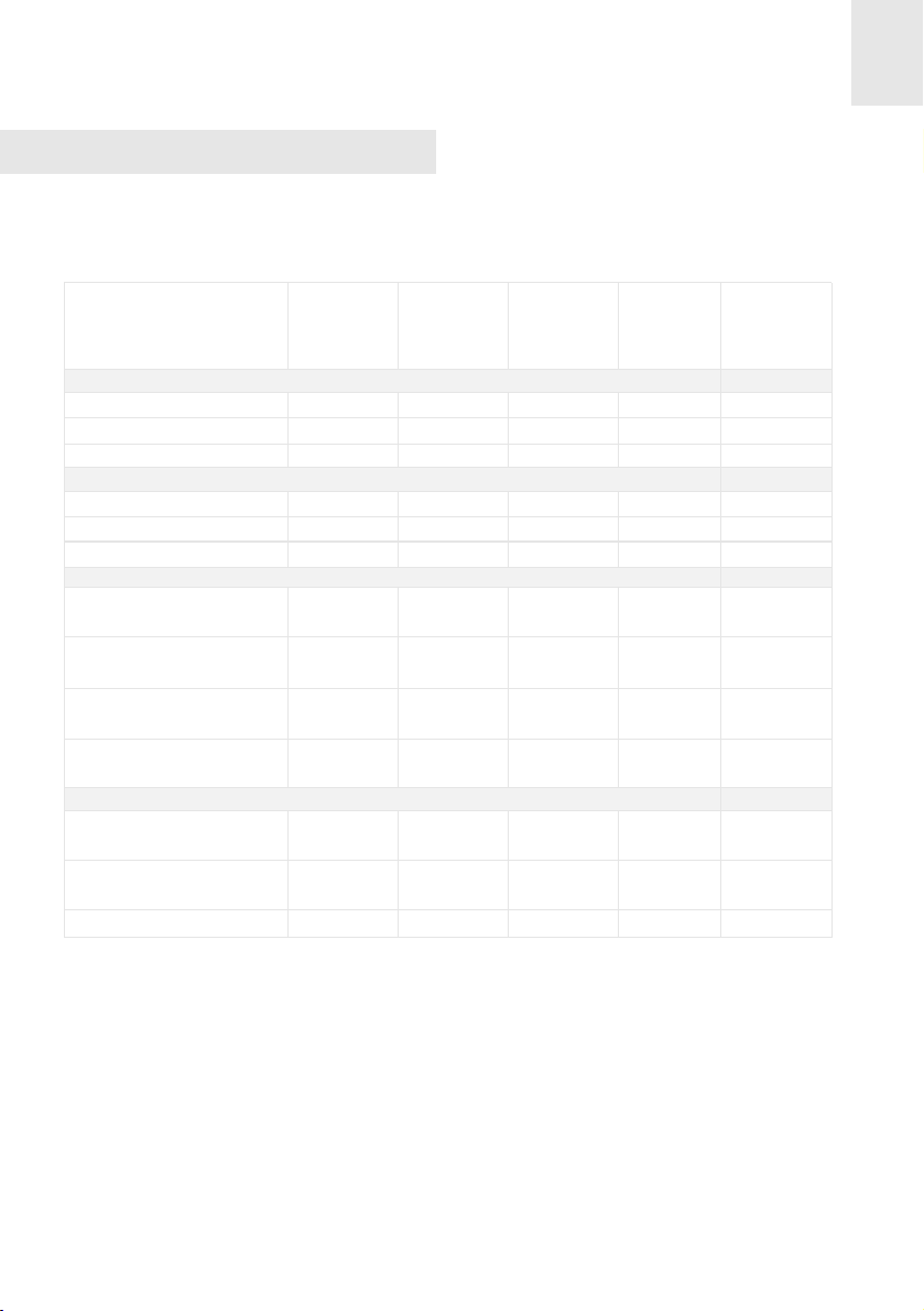
Technical Information
Technical details
Class 3 hob.
Dimensions and characteristics
Model
Hob dimensions
Height (mm)
Length (mm)
Width (mm)
Dimensions of the placement in the unit
Length (mm)
Width (mm)
Depth (mm)
Configuration
Induction hotplate
1,100 / 1,800*
Induction hotplate
1,600 /2,300* W
Inducción hotplate
2,100 / 3,000* W
Double induction hotplate
1,500/1,800* and 2,400/3,200* W
Electrics
Nominal Power
(W) for 230 V
Supply
voltage (V)
Frequency (Hz)
* Induction power with the Power function enabled.
(L)
(W)
W
IR 631
IT 631
60
600
510
560
490
55
1
1
1
6.400
50 / 60
IR 641
IT 641
60
600
510
560
490
55
6.400
230 V230 V
50 / 60
IR 630
IT 630
IRC 631
IR 831
GKI 630
60
600
510
560
490
55
1
2
1
1
60
590
510
570
490
55
1
1
65
800
400
780
380
61
1
1
1
1
6.100
230 V
50 / 60
1
6.100
230 V
50 / 60
1
6.400
230 V
50 / 60
11
Page 12

GB
Use and Maintenance
Before starting for the
first time
Before connecting the hob to the electrical
network, verify that the tension (voltage)
and the frequency of the hob correspond
to the voltage and frequency indicated on
the hob rating plate, which is located on
the underside of the hob and in the guarantee or, if applicable, on the technical
data sheet that should be kept with this
manual during the useful life of the apparatus.
The appliance is not designed to
be used by people (including children)
with reduced physical, mental or sensory abilities. It should also not be used
by people that do not have experience
handling the apparatus or who do not
have knowledge of the apparatus,
unless they are supervised by a person
who is in charge of their safety.
Children should not be allowed
to play with the apparatus.
The induction generator complies
with the European regulations in force.
We recommend, however, that people
using pacemaker heart devices or similar consult their doctor or, if in doubt,
refrain from using the induction areas.
Touch control user
instructions
CONTROL PANEL ELEMENTS(see fig. 3)
1
On/off sensor.
2
Hotplate indicators.
Power and/or residual heat indicators.
3
Reduce power sensor (less).
4
Increase power sensor (more).
5
Timer/Clock indicator.
6
Indicator of selected time (clock).
7
Locking sensor (for the rest of the sen-
8
sors, except on/off).
Indicator light of the induction element
9
with timer.
10
Pilot light for activated locking.
Time reduction sensor on clock (less).
11
Time increasing sensor on clock (more).
12
Countdown indicator (blinks each
13
second) .
N.B.: * Only visible when in operation.
The sensors marked on the control panel
are used for control purposes.
There is no need to exert pressure on the
glass - you enable the function you require simply by touching the sensor with your
finger.
Each action is confirmed by a beep.
12
fig. 3
Page 13

GB
SWITCHING THE APPLIANCE ON
SWITCHING THE HOTPLATES OFF
1 Touch the on sensor (1) for at least
one second. The Touch Control will activate, you will hear a beep and the indicators will turn on. If any of the cooking
areas is hot, the corresponding indicator
will alternate between showing a H and
a 0.
The following action must be carried out
within 10 seconds or the touch control will
automatically switch off.
When the touch control is activated, it can
be disconnected at any time by touching
the sensor (1), even if it has been
blocked (blocking function activated). The
sensor (1) always takes priority for disconnecting the touch control.
SWITCHING THE HOTPLATES ON
The hotplates will be found deactivated,
with their respective power indicators (3)
at 0, until a power level is selected. If all
the hotplates are set at 0, you have 10
seconds to activate any of them, otherwise
the touch control will automatically turn off.
Use the sensors and (4/5) to select
a power level. If you touch the sensor
(5), the plate will switch to level 1 and,
for each additional stroke, it will go up one
level until reaching the maximum value of
P. Using the sensor (4), you can redu-
ce the power level.
With the sensor (4), lower the power to
level 0.
The hotplate will automatically power off.
For a fast power up: no matter what the
power level, by simultaneously pressing
the sensors and (5/4), the plate will
immediately power off.
By powering off a hotplate, an H will be
shown on the power indicator, if the glass
surface is at a high temperature, indicating
that there a risk of burning. When the temperature has fallen, the indicator will power
off if the top is disconnected or, if it is turned on, it will indicate a 0.
POWERING OFF THE DEVICE
At any time, you can disconnect the top by
pressing the sensor (1). When doing
this, an acoustic signal is heard and the
power indicators (3) will turn off, except if
there is a residual H heat indicator active
due to the plate temperature.
Locking the sensors
Using the locking sensor (8), you can
block all the sensors on the touch control
panel. This will make it possible to avoid
undesired accidental operations occurring
or children being able to manipulate the
control.
For a fast powering up at maximum power:
with the plate at 0, touch the sensor (4)
once. The plate will directly activate at
level 9.
By continuing to press down on any of
these two sensors (4) or (5), they
will repeat the action every half a second,
without needing to press consecutively.
Bear in mind that with the touch control
powered up, the on/off sensor (1)
makes it possible to turn it off even if the
locking is activated (pilot 10 on). On the
other hand, if the touch control is turned
on, the locking function does not allow for
activating the on/off sensor (1). You
should first deactivate blocking.
13
Page 14

GB
To activate or deactivate the function,
simply keep pressing the sensor (8)
for about 1 second. When the function is
active, the pilot light (10) turns on.
Detecting pans
(induction hotplates)
The induction cooking plates incorporate a
container detector. This is to avoid the
plate operating without having a pan on
top or when the container is unsuitable,
e.g., if made of aluminium or another nonmetallic material.
The power indicator blinks if, with the plate
turned on, no container or an inappropriate container is detected.
If the containers are removed from the hotplate while operating, this will automatically cut off the power supply and the
power indicator will blinks. When putting
the container on the cooking hotplate
again, the power supply restarts at the
power level that was selected.
The time for detecting the container is 3
minutes. If three minutes go by without
having placed a container on the hotplate
or if an inappropriate container is placed
there, the cooking plate deactivates.
After use, always disconnect the
cooking plate. It is not sufficient to
remove the container. Otherwise, undesirable operation of the plate may occur
if another container were placed by
mistake during the container detection
period. Avoid possible accidents!
Power supplied according to
the power level selected
Bear in mind that induction areas adjust the
amount of power supplied according to the
size and type (material) of pan placed on
them. A smaller pan will receive less power
than a larger one. Thus, depending on the
pan being used, the power supplied may
vary from the values shown in Table 1.
Table 1
INDUCTION HOTPLATES
Power
selected
o
1
2
3
4
5
6
7
8
9
P
*The exact power will depend of the size and shape of the pan.
Ø 260 mm Hotplate
Inner area Both areas
54
72
120
180
276
450
600
840
1140
1440
1800
90
120
200
300
460
750
1000
1400
1900
2400
3200
14
Power in watts*
Ø 210 mm
Hotplate
70
110
150
240
500
600
850
1100
1550
2100
3000
Ø 180 mm
Hotplate
50
90
120
170
300
450
600
850
1150
1600
2300
Ø 145 mm
Hotplate
40
70
100
140
200
300
450
600
800
1100
1800
Page 15

GB
Power function
This function makes it possible to give a
plate "extra" power, higher than the nominal. This power level depends on the size
of the plate (see values indicated with * in
the Presentation section), reaching up to
3.200 W on the larger plates.
POWER FUNCTION CONNECTION
have its power limited to the remaining
power up to a total of 3,200 Watts. If the
power level on this plate is too high, the
touch control will automatically reduce it to
the maximum allowed (7).
Fondue function
This function is especially designed for
melting butter, cheese, chocolate, etc. It is
a lower power level than level 1.
1 Activate the plate corresponding to
power level 9.
2 From power level 9, press the sensor
and the symbol P will be displayed
on the indicator.
The Power function lasts for a maximum of
10 minutes. After this time, the power level
will automatically set to level 9.
POWER FUNCTION DISCONNECTION
The Power function can be disconnected
by pressing the sensor associated with
the hotplate in question.
The function can also be disconnected
automatically if the temperature in the cooking area is very high.
Bear in mind that the 3 and 4 model of plates have 2 independent power generators
of 3,200 W each, which respectively control the plates on the left and on the right.
For this reason, the Power function cannot
be activated at the same time in two plates
on the same side. In other words, if this
function operates in a plate on the left, the
Power cannot be activated on the other
plate on the other side, but it can be activated on the other plate on the other side.
To access this function:
1 Activate the plate you wish to use at
power level 1.
2 Press the sensor (4) and the indica-
tor will show the symbol .
To deactivate the function, simply touch
the sensors (4) or (5) and the indicator will display, respectively, a lower
power level 0 or higher 1.
Safety disconnection
MAXIMUM FUNCTION TIME
In the event of forgetting to turn off the plate,
it will automatically power off after a given
time after the last time the plate was activated. (See Table 2).
Once this function has been activated in a
hotplate, the one on the same side will
15
Page 16

GB
Table 2
Power
selected
1
2
3
4
5
6
7
8
9
P
When the "safety disconnecting" has occurred, in the corresponding plate's power
indicator the residual heat H indicator will
be displayed, if the glass temperature is
high enough.
SAFETY WHEN SENSORS ARE COVERED
MAXIMUM
OPERATION TIME
(in hours)
8
8
5
4
4
3
3
2
2
1
10 minutes
Take into account that this safety
function is activated even though the
Touch Control is turned off!
Do not leave any objects down on
the Touch Control!
Clock
(except models …630)
The top is fitted with a clock that can be
used for two different functions: as a plate
timer or as a countdown chronometer.
The clock as a countdown timer
(except models …630)
With this function, you can set a time after
which a sound signal will be heard.
To activate this function, proceed as
follows:
1 With the Touch Control powered on and
no plate with the timer activated, touch
one of the sensors (11) or (12)
corresponding to the clock.
The Touch Control incorporates a function
that detects when any object (container,
cloth or certain liquids) are covering the
panel sensors for more than 10 seconds.
This is to avoid the object activating or
deactivating any of the plates without you
realizing.
When the Touch Control detects an object
covering the sensors, it starts to bleep until
the object covering the control panel is
removed. If the Touch Control was turned
on, it is automatically disconnected for
safety reasons.
If after a few minutes the object covering
the sensors is not removed, the bleeping
will stop.
16
2 Power on the indicator (7), displaying
00.
3 Touch the sensors (11) or (12)
again to set the required time. After a
few seconds, the decimal point on clock
will start to blink (13), indicating that the
countdown has begun.
Be careful not to touch different sensors
other than (11) or (12) since, by
doing so, a plate may cease timing instead
of programming the chronometer.
Once the countdown has reached zero, a
series of bleeps will be heard. These can
be cancelled by touching any of the sensors (11) or (12) associated with
Page 17

GB
the clock.
tor (7) will start to blink.
If, while the clock is working as a countdown chronometer, at some point the
induction plates are set at power level 0,
the touch control panel will turn off after a
few seconds, but the chronometer will continue working until it finishes the countdown or the countdown is cancelled.
To cancel the chronometer, simply set the
remaining time to 00.
Timer function
(except models …630)
This function will help you with cooking as
you will not have to be present during the
following: the timer plate(s) will automatically turn off at the end of the set time. The
device has an individual timer for each
plate. This allows it to time all the plates at
the same time, if required.
The function is controlled with the time
increase/decrease sensors and
(11/12) associated with the clock (7).
SINGLE plate timer
To activate the timer on one single plate,
proceed as follows:
1 With the plate powered on and the clock
turned off, touch one of the sensors
(11) or (12) corresponding to the
clock.
2 Turn on the indicator (7) displaying 00.
At the same time, a blinking will appear on the indicators for each of the plates that are powered on.
3 In the next 5 seconds, touch one of the
sensors (4) or (5) corresponding to the plate you wish to time. The
will be set on the indicator for this
plate and the digits on the clock indica-
4 You have a further 5 seconds to select
the time required, simply by touching the
sensors (11) or (12) on the
clock. After a few seconds, the digits on
clock indicator (7) will stop blinking and
the decimal point on the clock and the
timed plate will start to blink, indicating
that the countdown has started.
Once the required time has been set, be
careful not to activate any other sensor
since the device may interpret that you
wish to exit the timer function. While the
clock digits blink, you can alter their value
but do not touch different sensors other
than (11) or (12).
Once the countdown is complete, the
timed plate will power off and a series of
bleeps will be heard that can be cancelled
by touching any of the sensors (11) or
(12) associated with the clock.
Timing more than one plate / Altering
the programmed time
During a countdown, you can alter the
remaining time or time a new plate.
1 With the Touch Control powered on and
a plate timed, touch one of the sensors
(11) or (12) corresponding to the
clock.
2 The countdown will stop and the indica-
tor (7) displays 00. A blinking will display on the indicators for each of the plates that are powered up.
3 At that point, you can time another plate
or alter the remaining time on a previously time set plate. To distinguish
them, take into account the decimal
point appearing on the bottom right
of the indicator (3), only on that/those
plate/s that are timed at that moment.
17
Page 18

GB
In the next 5 seconds, touch one of the
sensors (4) or (5) corresponding
to the plate that you wish to time or alter.
The will stop blinking in the indicator
for this plate and the digits on the indicator (7) of the clock will start to blink.
4 Touch the sensors (11) or (12)
again until the required time is set. After
a few seconds the decimal point in the
indicator (7) will start to blink, indicating
that the countdown has started.
minutes to cool the electronics if you
switch the cooker off when the fan is switched on.
Power surges
Touch controls can withstand a
certain degree of power surges in the
electricity supply. Abnormally high
power surges can cause the control
system to malfunction (as with any type
of electrical appliance).
If you wish to cancel a timing already set,
simply set the time desired in step 4 to 00 or,
directly, by turning off the plate in question.
When you have timed more than one
plate, by default, the indicator (7) of the
clock will display the shortest remaining
time. This time will correspond to the plate
whose indicator (3) displays the blinking
with the decimal point.
Remember that the decimal point in a
power indicator (3) shows you that this plate
is timed! If this decimal point is blinking and
it’s shown the , it means that the indicator
(7) of the clock is showing you, at that precise moment, the time remaining in the
countdown for that hotplate.
Please remember that if, during the
countdown, you turn off the touch panel
using the on/off sensor button (1),
the countdown will be cancelled!
Overheating safety feature
The induction areas are protected against
overheating that may cause damage to the
electronic system.
The internal fan is automatically enabled
and disabled, depending on the temperature of the electronic system. Therefore,
the fan may continue to work for a few
Suggestions and
recommendations
To ensure maximum performance from
your hob, follow these guidelines:
fig. 4
Right
* Use pans with a flat base, as the greater
the surface contact between the pan
and the glass, the greater will be the
heat transmission. We recommend the
use of heavy pans so that the base is
more difficult to dent. Figure 4 shows
how pans that are dented or concave
have a smaller contact surface.
* Make sure that the pans are well centred
on the outlines shown on the heating
area.
* Dry the pans’ bases before putting them
on the glass ceramic hob.
* Do not drag pans with corners or edges
that could damage the glass.
* The glass withstands some impacts from
large containers with no sharp edges.
Be careful with impacts from small and
sharp utensils.
Wrong
Wrong
18
Page 19

GB
* Avoid spilling sugar, or products contai-
ning sugar, on the glass, since these
may react with the hot glass and damage the surface.
Cleaning and care
To maintain the glass ceramic hob in good
condition, it should be cleaned with suitable products. The glass ceramic hob
should be cleaned after each use, when it
is lukewarm or cool. This will make cleaning easier as it will avoid any build-up of
dirt from repeated use.
Never use aggressive cleaning products or
products that can scratch the surfaces
(see the table that shows various common
products that may be used). Steam-based
appliances should not be used to clean the
hob.
LOOKING AFTER THE GLASS
The degree of soiling should be taken into
account when cleaning, and the items and
products used should vary according to
this.
Light soiling
Light, non-sticky, soiling can be cleaned
with a damp cloth and a soft detergent or
warm, soapy water.
Heavy soiling
Serious dirt and grease should be cleaned
using an agent specially made for glass
ceramic (for example, Vitroclen). Please
follow the manufacturer’s instructions.
Sticky stains that have been burned in can
be removed by using a scraper with a
razor blade.
Rainbow colouring: Caused by pans that
have dry bits of grease on their base or
when grease gets between the glass and
the pan while cooking. Can be removed
from the surface of the glass using a nickel
scourer with water or with a special glass
ceramic cleaner (for example, Vitroclen).
Plastic objects, sugar, or food with a high
sugar content that are melted onto the hob
should be removed immediately while hot,
using a scraper.
RECOMMENDED CLEANING PRODUCTS
Product
Soft and liquid detergents
Aggressive or powder detergents
Special glass ceramic cleaning agents (e.g. Vitroclen)
Grease-removing sprays (ovens, etc.)
Soft cloths
Kitchen towels
Kitchen cloths
Nickel scourers (never use dry)
Steel scourers
Hard synthetic scourers (green)
Soft synthetic scourers (blue)
Glass scrapers
Liquid polish for domestic appliances and/or glass
Should it be used to clean...
...the glass? ...the surround?
YES YES
NO NO
YES YES
NO NO
YES YES
YES YES
YES YES
YES NO
NO NO
NO NO
YES YES
YES NO
YES YES
19
Page 20

GB
When the glass’s colour changes.
This does not affect its effectiveness or
stability, and is generally caused by inadequate cleaning or by poor-quality pans.
Metallic sheens are caused by metal pans
sliding over the glass. They can be removed by thorough cleaning with a special,
glass ceramic cleaning agent (for example, Vitroclen), although it may be that the
cleaning needs to be repeated more than
once.
Worn trim is the result of using abrasive
cleaning products or pans with uneven
bases which wear down the serigraphy.
Use blades that are in perfect conditions, and change the blade as soon
as it shows any sign of wear.
When you finish using the scraper, fold it away and cover it well up.
(See fig. 6)
fig. 6
Protected blade Unprotected blade
Using the scraper
Please note:
Take great care when using the
glass scraper. The blade can cause
injury!
If you do not use the scraper properly, the blade could break and pieces
may get stuck between the decorative
side-piece and the glass. If this happens, do not try to remove the pieces
with your hand - use pliers or a sharppointed knife. (See fig. 5)
fig. 5
Only use the blade on the glass
ceramic surface - avoid the body of the
scraper coming into contact with the
glass, since this could scratch the
glass ceramic.
Pans may stick to the glass if
something has melted between them.
Do not attempt to unstick the pan when
it is cold - you could break the glass
ceramic.
TEKA INDUSTRIAL S.A. reserves the
right to alter its manuals in any way it
deems necessary or useful while not altering their basic characteristics.
The symbol on the product or on its
packaging indicates that this product
may not be treated as household waste.
Instead it shall be handed over to the
applicable collection point for the recycling of electrical and electronic equipment. By ensuring this product is disposed of correctly, you will help prevent potential negative consequences
for the environment and human health,
which could otherwise be caused by
inappropriate waste handling of this
product, please contact your local city
office, your household waste disposal
service or the shop where you purchased the product.
20
Page 21

GB
If something doesn’t work
Before calling the Technical Service, please
make the following checks:
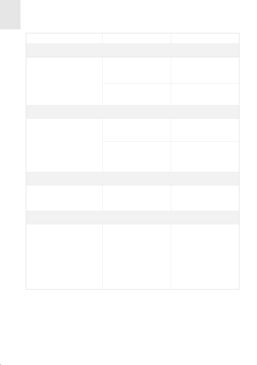
Fault Possible cause Possible solution
The induction zones are not heating up
The pan is unsuitable (it
does not have a ferromag-
netic base or it is too
small).
When you start using the induction zones, you hear a buzzing sound
The pan is light or made
up of more than one part.
The buzzing comes from
energy being transmitted
directly to the base of the
The touch control does not come on
The sound of a fan can be heard while cooking, and it continues when
the cooker has been turned off.
induction zones to cool
pan.
The lock is enabled
There is a fan in the
the electronics.
Check that the pan base
reacts to a magnet, or use a
This buzzing is not a fault. If,
however, you wish to avoid it,
lower the power level slightly
or use a pan that has a hea-
vier base, and/or that is made
The fan only comes on when
cally, whether or not the hob
larger pan.
of a single part
Disable the lock.
the electronics heat up -
when the temperature goes
down it goes off automati-
is on.
When frying or making a stew, the energy in the induction zones seems
to decrease (“the hotplate gets less hot”)
If the temperature of the
glass or of the electrics
gets too high while coo-
king, a self-protection
system is triggered that
adjusts the power of the
hotplates so that the temperature does not get any
A plate powers off and message C is displayed on the indicators
Excess temperature in the
electronics or on the glass.
higher.
Overheating problems while
cooking only occur under
conditions of extreme use
(cooking for a long time at full
power) or when the hob has
been wrongly installed.
Check that the hob has been
installed as described in the
instruction manual.
Wait some time to allow the
electronics to cool down or
remove the container to
allow the glass to cool.
21
Page 22
GB
Fault Possible cause Possible solution
The hob suddenly starts to bleep
There is a cloth, container
or liquid on the Touch
Control.
The timer was activated
and the preset time has
finished.
The hob (or any of the hotplates) powers off during cooking
There is a container, cloth
or liquid covering the Touch
One or several of the hot-
A timed hotplate failed to power off at the end of the set time
The hotplate had not been
After a power outage (or the first time the hob is connected), the
control panel remains blocked
affecting the control panel.
Control.
plates has overheated.
set correctly.
There is a powerful light
Remove any object covering
the Touch Control and/or
clean any liquid that might
have been spilt on it.
Touch the clock sensor to
deactivate the bleep.
Remove any object that
might be covering the
Touch Control.
Allow the overheated hot-
plates to cool down for a
few minutes before powe-
ring them up again.
Make sure that the time
was set following the ins-
tructions manual.
Don't apply powerful lights
(for example, halogen spo-
tlights) over the control
panel when connecting the
hob to the electrical
current. A very powerful
light may cause the sensor
buttons not to calibrate
correctly after a power
outage.
22
 Loading...