

Page 1

www.teka.com
EN User Manual
FR Manuel d’Utilisation
GZC SERIES
Page 2

2
TYPE: PCZT
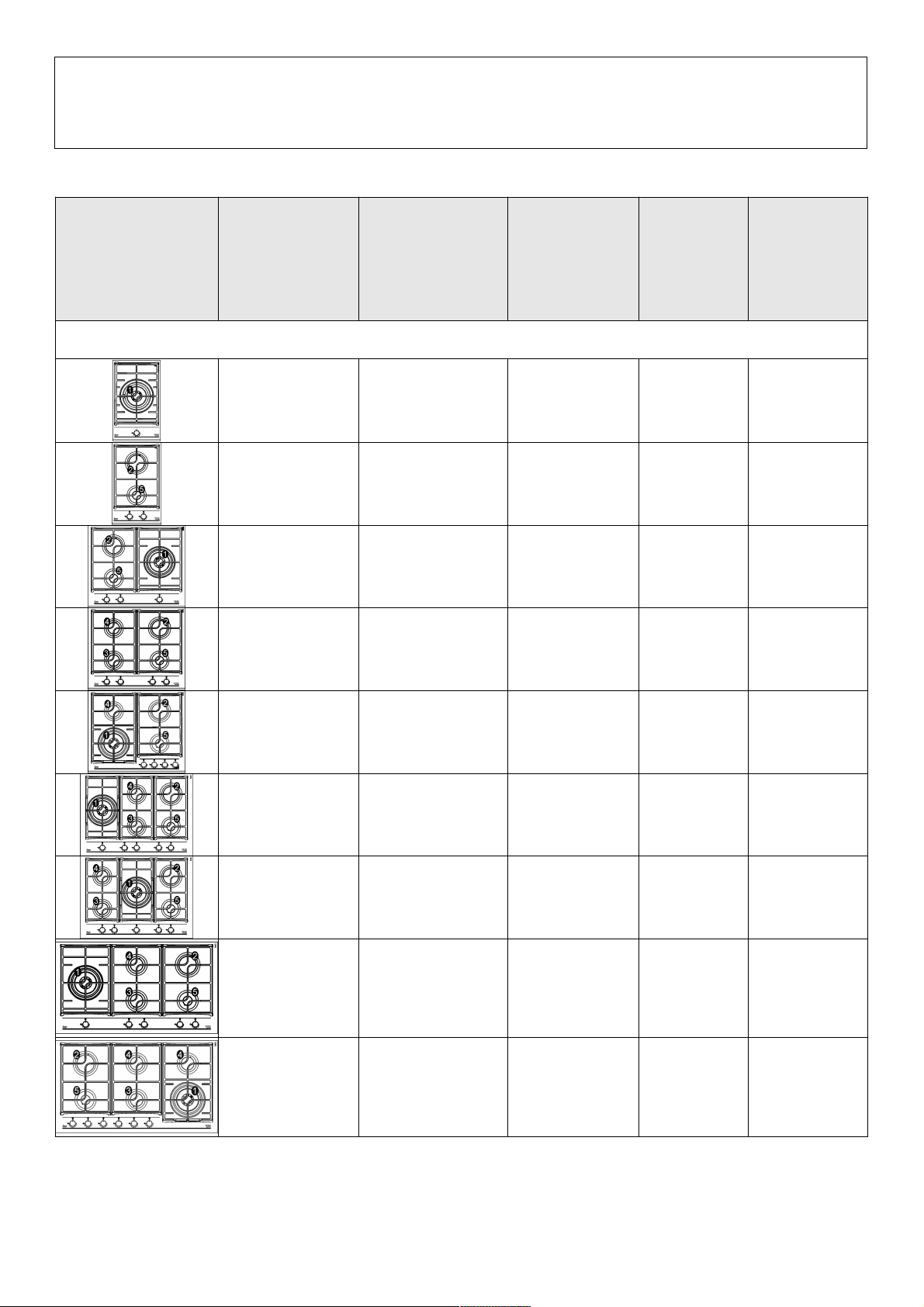
Models / modèle GZC 31330
GZC 32300
GZC 63310
GZC 64300
GZC 64320
GZC 75330
GZC 85320
GZC 95320
GZC 96310
Page 3

3
WARNING:
Children less than 8 years of age shall be kept away unless
continuously supervised.
This appliance can be used by children aged from 8 years
and above and persons with reduced physical, sensory or
mental capabilities or lack of experience and knowledge if
they have been given supervision or instruction concerning
use of the appliance in a safe way and understand the
hazards involved.
Children shall not play with the appliance.
Cleaning and user maintenance shall not be made by
children without supervision.
INDEX:
Pag. 4 Description
pag. 6 Important safety warnings
pag. 14 Technical data for the appliance gas regulation
pag. 15 Technical data on the data label
pag. 16 Use
pag. 17 Cleaning - Installation
pag. 18 Fixing
pag. 19 Installation - Gas connection
pag. 20 Installation - Electrical connection - Regulation taps
pag. 21 Conversion
pag. 22 Servicing
pag. 23 Technical assistance and spare part
Page 4

DESCRIPTION
1 Ultra rapid gas burner (*DCC AFB) of 4000 W
2 Rapid gas burner of 2800 W
3 Semirapid gas burner reduced of 1400 W
4 Semirapid gas burner of 1750 W
5 Auxiliary gas burner of 1000 W
7 Burner n° 1 control kno
8 Burner n° 2 control knob
9 Burner n°3 control knob
10 Burner n° 4 control knob
11 Burner n° 5 control knob
*DCC AFB: Air From The Bottom (fig. 13/B).
Attention: this appliance has been manufactured for domestic use only and it employment by
private person.
This cook top was designed to be used exclusively as a
cooking appliance: any other use (such as heating rooms) is to
be considered improper and dangerous.
4
Page 5

5
DESCRIPTION
GZC 95320
GZC 75330
GZC 85320GZC 64320GZC 64300
GZC 96310
GZC 63310GZC 32300GZC 31330
Page 6

6
IMPORTANT SAFETY WARNINGS
IMPORTANT WARNINGS FOR THE
USER
During operation the wo rk surfa ces of the
cooking area become very hot: keep children
away!
CAUTION:
In case of hotplate glass breakage:
●shut immediately off all burners and any electrical
heating element and isolate the appliance from the
power supply;
●do not touch the appliance surface;
●do not use the appliance.
●IMPORTANT!
A perfect ins ta llation, adj ustment or
transformation of the cook top to use other
gases requires a QUALIFIED INSTALLER: a
failure to follow this rule will void the warranty.
●IMPORTANT: the appliance must be installed
following the manufacturer's instructions. The
manufacturer will not be liable for injury to
persons or animals or property damage caused
by an incorrect installation.
●If the installation requires modifications to the
home's electrical system or if the socket is
incompatible with the appliance's plug, have
changes or repl acements perf ormed by
professionally-qualified person. In particular,
this person must also make sure that the
section of the wires of the socket is suitable for
the power absorbed by the appliance.
●Use of a gas cooking appliance produces heat
and moisture in the room in which it is installed.
The room must therefore be well ventilation by
keeping the natural air vents clear (see fig. 3)
and by activating the mechanical aeration
device (suction hood or electric fan fig. 4 and
fig. 5).
●Intensive and lengthy use of the appliance may
require additional ventilation. This can be
achieved by opening a window or by increasing
the power of the mechanical exhausting system
if installed.
●Do not attempt to change the technic al
characteristics of the product because it can be
dangerous.
●If you should not to use this appliance any more
(or replace an old model), before disposing of it,
make it inoperative in conformity with current
law on the protection of hea lth and the
prevention of environmental pollution by making
its dangerous parts harmless, especially for
children who might play on an abandoned
appliance.
●CAUTION:
Do not touch the appliance with wet or damp
hands or f eet. Do not use the appliance
barefoot
●The manufacturer will not be liable for any
damage resulting from improper, incorrect or
unreasonable use.
●During, and immediately after operation, some
parts of the cook top are ve ry hot: avoid
touching them.
●After using the cook top, make sure that the
knob is in the closed position and close the
main tap of the gas supply or gas cylinder.
●If the gas taps are not operating correctly, call
the Service Department.
●Keep the Warranty Certificate or the sheet of
technical data with the Instructions Handbook
during the appliance life. It contains important
technical data.
IMPORTANT:
All our products are conform with the
European Norms and relative amendments.
The product is therefore conform with the
requirements of the European Directives in
force relating to:
- compatibility electromagnetic (EMC);
- electrical security (LVD);
- restriction of use of certain hazardous
substances (RoHS);
- EcoDesign (ERP).
The appliance complies with the provisions of
the sub-regulations for European Directives:
- Regulation (EU) 2016/426.
Page 7

7
FIG. 6 FIG. 6/A FIG. 6/B
FIG. 3 FIG. 4 FIG. 5
FIG. 2
USE - UTILISATION
CLEANING - NETTOYAGE
(*) air inlet: see installation chapter (paragraphs 5 and 6)
(*) entree d’air: voir chapitre installation (paragraphes 5 et 6)
Page 8

8
FIG. 7
FIG. 8
FIG. 8/A
INSTALLATION
horizontal wooden insert
inserte en bois horizontal
Page 9

INSTALLATION
FIG. 9
INSTALLATION TYPE A: Lateral chrome / cote chrome
FIG. 9/A
FIG. 9/B
Model /
modèle
:
GZC 63310
GZC 64300
GZC 64320
GZC 64321
GZC 75330
GZC 85320
Model /
modèle
: GZC 95320
GZC 96310
Page 10

10
INSTALLATION TYPE A: Rear black / arrière noirs
FIG. 10/BFIG. 10/A
FIG. 10
Model /
modèle
: GZC 95320
GZC 96310
INSTALLATION
Model /
modèle
:
GZC 63310
GZC 64300
GZC 64320
GZC 64321
GZC 75330
GZC 85320
Page 11

11
INSTALLATION
Procedure for a correct installation
of the hob
Procédure pour une installation correcte de la table
de cuisson
Page 12

12
INSTALLATION TYPE: B
(mm)
INST.
TIPO:
A B C D E F
GZC 32300
B
280 490 55 55 160 70 min.
GZC 31330
B
280 490 55 55 160 70 min.
GZC 63310
A
570 480 60 60 165 70 min.
GZC 64300
A
570 480 60 60 165 70 min.
GZC 64320
A
570 480 60 60 165 70 min.
GZC 75330
A
570 480 60 60 165 70 min.
GZC 85320
A
570 480 60 60 165 70 min.
GZC 95320
A
850 480 60 60 65 70 min.
GZC 96310
A
850 480 60 60 65 70 min.
FIG. 11
FIG. 11/A FIG. 11/B
COMPLY WITH THE DIMENSIONS (in mm)
DIMENSIONS A RESPECTER (en mm)
Model /
modèle
:
GZC 32300 / GZC 31330
INSTALLATION
Page 13

13
FIG. 12 FIG. 12/A
FIG. 13
FIG. 13/B
FIG. 13/A
FIG. 14
INSTALLATION
CONVERSIONS - TRANSFORMATIONS
Page 14

14
TECHNICAL DATA FOR THE
APPLIANCE GAS REGULATION
In case of adaptation of the hob to another type of
gas, operate as described in the directions for the
and installation use and replace the label on the bottom
with the one provided in the spare bag.
Page 15

15
TECHNICAL DATA ON THE DATA LABEL
ΣQn
NATURAL
NATUREL
G20
20 mbar
ΣQn
BUTANE
G30
28 - 30 mbar
ΣQn
PROPANE
G31
37 mbar
VOLTAGE
TENSION
V~
EEgashob
CATEGORY = II2H3+ FREQUENCE 50 - 60 Hz
4.0 kW 291 gr/h 286 gr/h 220-240 56,0 %
3.80 kW 276 gr/h 271 gr/h 220-240 58,0 %
7.80 kW 567 gr/h 557 gr/h 220-240 57,0 %
6.95 kW 505 gr/h 496 gr/h 220-240 60,3 %
9.55 kW 694 gr/h 682 gr/h 220-240 58,3 %
10.95 kW 796 gr/h 782 gr/h 220-240 59,30 %
10.95 kW
796 gr/h 782 gr/h 220-240 59,30 %
10.95 kW
796 gr/h 782 gr/h 220-240 59,30 %
12.70 kW
923 gr/h 907 gr/h 220-240 59,40 %
Page 16

16
1) BURNERS
A diagram is screen-printed above each knob on
the front panel. This diagram indicates to which
burner the knob in question corresponds. After
having opened the gas mains or gas bottle tap,
light the burners as described below:
- automatic electrical ignition
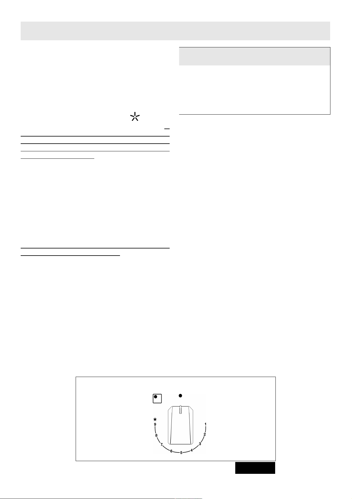
Push and turn the knob corresponding to the
required burner in an anticlockwise direction until it
reaches the full on position of full (position 9
fig. 1), then depress the knob, the tap is equipped
with a scale of 9 positions, with each click the
flame is reduced until you reach the position of 1,
ie the minimum supply of gas.
- Lighting burners equipped with flame failure
device
The knobs of burners equipped with flame failure
device must be turned in an anticlock wise
direction until they reach the full on position
(Position 9, fig.1) and come to a stop. Now
depress the knob in question and repeat the
previously indicated operations.
Keep the knob depressed for about 10 seconds
once the burner has ignited.
Then follow the instructions for using the tap as
explained above.
With regards to al l the models, in case of
accidental extinguishment of the flame, disengage
the ignition by rotating the knob to the off position.
Wait at least 1 minute before re-igniting the flame.
HOW TO USE THE BURNERS
Bear in mind the following indications in order to
achieve max imum efficiency with the least
possible gas consumption:
- use adequate pans for each burner (consult the
following table and fig. 2).
- When the pan comes to the boil, set the knob to
the reduced rate position (Position 1, fig. 1).
- Always place a lid on the pans.
- Use only pan with a flat bottom.
WARNINGS:
- burners with flame failure device may only be
ignited when the relative knob has been set to
the Full on position (Position 9, fig. 1).
- Matches can be used to ignite the burners in a
blackout.
- Never leave the appliance unattended when
the burners are being used. Make sure there
are no children in the near vicinity. Particularly
make sure that the pan handles are correctly
positioned and keep a check on foods
requiring oil and grease to cook since these
products can easily catch fire.
- Never use aerosols near the appliance when it
is operating.
- Containers wider than the unit are not
recommended.
USE
Burners Pan Ø in cm
Ultrarapid 24 ÷ 26
Rapid 20 ÷ 22
Semirapid reduced 16 ÷ 18
Semirapid 16 ÷ 18
Auxiliary
10 ÷ 14
Closed position
9) Full position
1) Reduced
rate position
FIG. 1
Page 17

17
INSTALLATIONCLEANING
IMPORTANT:
always disconnect the appliance from the gas
and electricity mains before carrying out any
cleaning operation.
2) GAS HOB
It is very important to clean the surface soon after
every use, when the glass is still tepid.
Periodically wash the gas hob, the enameled steel
pan support, the enameled burner caps “A”, “B” and
“C” and the burner heads "T" (see fig. 6 - 6/A) with
lukewarm soapy water. They should also be
cleaned plugs "AC" and flame detection "TC" (see
fig. 6). Clean them gently with a small nylon brush
as shown (see fig. 6/B) and allow to dry fully.
Do not wash in the dishwasher.
Do not allow vinegar, coffee, milk, salted water,
lemon or tomato juice from remaining in contact
with the enameled surfaces for long periods of time.
Do not use metallic sponges, powder abrasives or
corrosive sprays.
WARNINGS:
comply with the following instructions, before
remounting the parts:
- check that burner heads slots (see fig. 6 6/A) have not become clogged by foreign
bodies.
- Check that enameled burner cap “A - B - C”
(fig. 6 - 6/A) have correctly positioned on the
burner head. It must be steady.
- The pan support must be placed in the
appropriate cente ring pins (Or on the
aluminium profile if present). Verifying the
perfect stability.
- Do not force the taps if they are difficult open
or close. Contact the technical assistance
service for repairs.
- Don’t use steam jets for the equipment
cleaning.
TECHNICAL INFORMATION
FOR THE INSTALLER
Installation, adjustments of controls and
maintenance must only be carried out by a
qualified engineer.
The appliance must be correctly installed in
conformity with curre nt law and the
manufacturer's instructions.
Incorrect installation may cause damage to
persons, animals or property for which the
Manufacturer shall n ot be consid ered
responsible.
During the life of the system, the automatic
safety or regulating devices on the appliance
may only be modified by the manufacturer or
by his duly authorized dealer.
3) INSTALLING THE GAS HOB
Check that the appliance is in a good condition after
having removed the outer packaging and internal
wrappings from around the various loose parts. In
case of doubt, do not use the appliance and contact
qualified personnel.
Never leave the packaging materials (cardboard,
bags, polystyrene foam, nails, etc.) within
children’s reach since they could become
potential sources of danger.
The measurements of the opening made in the top of
the modular cabinet and into which the gas hob will be
installed are indicated in either fig. 7. Always comply
with the measurements given for the hole into which
the appliance will be recessed (see fig. 7 and 8)
.
The appliance belongs to class 3 and is
therefore subject to all the provisions
established by the provisions governing such
appliances.
Note: continuous use could cause the burners to
change colour due to the high temperature.
Page 18

18
INSTALLATION
4) FIXING THE GAS HOB
INSTALLATION TYPE: A
The gas hob has a special seal which prevents
liquid from infiltrating into the cabinet. Strictly
comply with the following instructions in order to
correctly apply this seal:
- take off all the movable parts of the hob.
- Cut the seal in 4 parts of the necessary lenght to
positioning it on the 4 edges of the crystal.
- Overturn the gas hob and correctly position seal
“E” (fig. 11/A) under the edge of the gas hob
itself, so that the outer side of the seal perfectly
matches the outer perimetral edge of the crystal.
The ends of the strips must fit together without
overlapping.
- Evenly and securely fix the seal to the crystal,
pressing it in place with the fingers.
- Place the hooks in their respective positions, use
the hole no. 1 as reference for position lateral
(fig. 9) and hole no. 2 for positions rear (fig. 10).
- Secure hooks “G” by means of screws “F” (fig.
9/A for lateral, and fig. 10/A for rear).
- Insert the cooking hob in the hole of the kitchen
cabinet by exercising a certain level of force in
order to get over the resistance of the hooks (fig.
9/B for lateral and fig. 10/B for rear). See the
diagram on page 11.
- In order to avoid accidental touch with the
overheating bottom of the hob, during the
working, is necessary to put a wooden insert,
fixed by screws, at a minimum distance of 70
mm from the top (see fig. 7).
4/A) FIXING THE GAS HOB
INSTALLATION TYPE: B
The gas hob has a special seal which prevents
liquid from infiltrating into the cabinet. Strictly
comply with the following instructions in order to
correctly apply this seal:
- take off all the movable parts of the hob.
- Cut the seal in 4 parts of the necessary lenght to
positioning it on the 4 edges of the crystal.
- Overturn the gas hob and correctly position seal
“E” (fig. 11/A under the edge of the gas hob itself,
so that the outer side of the seal perfectly
matches the outer perimetral edge of the crystal.
The ends of the strips must fit together without
overlapping.
- Evenly and securely fix the seal to the crystal,
pressing it in place with the fingers.
- Position the hob in the hole in the unit and fasten
it in place using the appropriate screws “F” of the
fastening hooks “G” (see fig. 11).
- In order to avoid accidental touch with the
overheating bottom of the hob, during the
working, is necessary to put a wooden insert,
fixed by screws, at a minimum distance of 70
mm from the top (see fig. 7).
Caution: Do not allow the glass (A) lay directly on the work top. it is the metal bottom “carter”
(B) that has to be in touch with the work top (see fig. 11/B).
CAUTION:
do not place the glass directly on the
unit. The bottom of the hob must rest
on the unit.
Page 19

19
INSTALLATION
5) ROOM VENTILATION
It is essential to ensure that the room in which the
appliance is installed is permanently ventilated in
order to allow the appliance itself to operate
correctly. the necessary amount of air is that
required for regular gas combustio n and
ventilation of the relative room, the volume of
which must not be less than 20 m3. Air must
naturally flow through permanent openings in the
walls of the room in question. These openings
must vent the fumes outdoors and their section
must be at least 100 cm2(see fig. 3). Construction
of the openings must ensure that the openings
themse lves may never be blocked . Indirect
ventilation by air drawn from an adjacent room is
also permitted, in strict compliance with the
provisions in force.
CAUTION: if the burners of the cooking top are
without safety thermocouple, the ventilation
outlet must have a minimum 200 cm² section.
6) LOCATION AND AERATION
Gas cooking appliances must always dispose of
their combustion fumes through hoods. These
must be connected to flues, chimneys or straight
outside. If it is not possible to install a hood, an
electric fan can be installed on a window or on a
wall facing outside (see fig. 4). This must be
activated at the same time as the appliance (see
fig. 5), so long as the specificati ons in th e
provisions in force are strictly complied with.
7) GAS CONNECTION
Before connecting the appliance, check that
the values on the data label affixed to the
underside of the gas hob correspond to those
of the gas and electricity mains in the home.
A l abel on the appliance indicates the
regulating conditions: type of gas and working
pressure. Gas connection must comply with
the pertinent standards and provisions in
force.
When gas is supplied through ducts, the
appliance must be connected to the gas supply
system:
● with a rigid steel pipe. The joints of this pipe
must consist of threaded fittings conforming to
the standards.
● With copper pipe. The joints of this pipe must
consist of unions with mechanical seals.
● With seamless flexible stainless steel pipe. The
length of this pipe must be 2 meters at most and
the seals must comply with the standards.
When the gas is supplied by a bottle, the
appliance must be fuelled by a pressure governor
conforming to the provisions in force and must be
connected:
● with a copper pipe. The joints of this pipe must
consist of unions with mechanical seals.
● With seamless flexible stainless steel pipe. The
length of this pipe must be 2 meters at most and
the seals must comply with the standards. It is
advisable to apply the special adapter to the
flexible pipe. This is easily available from the
shops and facilitates connection with the hose
nipple of the pressure governor on the bottle.
● With rubber hose pipe in compliance with
standards. The diameter of this hose pipe must
be 8 mm and its length must be no less than
400 mm and no more than 1500 mm. It must be
firmly fixed to the hose nipple by means of the
safety clamp specified by standards.
WARNINGS:
remember that the gas inlet union on the
appliance is a 1/2" gas parallel male type in
compliance with ISO 228-1 standards.
Installation of stainless steel pipe and rubber
hose pipe must ensure that it is never able to
touch mobile parts of the built-in cabinet (eg.
drawers). Furtherm ore, it must not pass
through compartments that could be used for
storage purposes.
When using a rubber hose pipe, it is essential
to comply with the following instructions:
- no part of the pipe must be able to touch
parts the temperature of which exceeds 90
°C.
- The pipe must not be pulled or twisted,
throttled or tightly bent.
- It must not come into contact with sharp
edges or corners.
- It must be easy to inspect the entire pipe
length in order to check its state of wear.
- The pipe must be replaced within the date
stamped on the pipe itself.
Page 20
20
INSTALLATION
8) ELECTRICAL CONNECTION
The electrical connections of the appliance
must be carried out in compliance with the
provisions and standards in force.
Before connecting the appliance, check that:
- the voltage matches the value shown on the
specification plate and the section of the wires of
the electrical system can support the load, which
is also indicated on the specification plate.
- The electrical capacity of the mains supply
and c u r re n t s ock e ts su it th e ma x im u m
power rating of the appliance (consult the
data label applied to the underside of the
gas hob).
- The socket or system has an efficient earth
connection in compliance with the provisions and
standards in force. The manufacturer declines all
responsibility for failing to comply with these
provisions.
When the appliance is connected to the
electricity main by a socket:
- fit a standard plug “C” suited to the load indicated
on the data label to the cable. Fit the wires
following figure 8/A, taking care of respecting the
following correspondences:
Letter L (live) = brown wire;
Letter N (neutral) = blue wire;
earth symbol = green - yellow wire.
- The power supply cable must be positioned so
that no part of it is able to reach an temperature
of 90 °C.
- Never use reductions, adapters of shunts for
connection since these could create false contacts
and lead to dangerous overheating.
- The outlet must be accessible after the built-in.
When the appliance is connected straight to the
electricity main:
- install an omnipolar circuit-breaker between the
appliance and the electricity main. This circuitbreaker should be sized, in compliance with
current installation regulations.
- Remember that the earth wire must not be
interrupted by the circuit-breaker.
- For optimum safety, the electrical connection may
also be protected by a high sensitivity differential
circuit- breaker.
You are strongly advised to fix the relative yellowgreen earth wire to an efficient earthing system.
Before performing any service on the electrical
part of the appliance, it must absolutely be
disconnected from the electrical network.
Always disconnect the appliance from the
electricity main before making any adjustments.
All seals must be replaced by the technician at
the end of any adjustments or regulations.
Our burners do not require primary air
adjustment.
9) TAPS
“Reduced rate” adjustment
- Switch on the burner and turn the relative knob to
the “Reduced rate” position (small flame fig. 1).
- Remove knob “M” (fig. 12 and 12/A) of the tap,
which is simply pressed on to its rod. The by-pass
for minimal rate regulation can be: beside the tap
(fig. 12) or inside the shaft. In any case, to access
to regulation, it can be done through the insertion
of a small screwdriver ‘’D’’ beside the tap (fig. 12)
or in the hole ‘’C’’ inside the shaft of the tap
(fig 12/A). Turn the throttle screw to the right or left
until the burner flame has been adequately
regulated to the “Reduced rate” position.
The flame should not be too low: the lowest small
flame should be continuous and steady. Reassemble the several components.
It is understood that only burners operating
with G20 gas should be subjected to the above
mentioned adjustments. The screw must be
fully locked when the burners operate with G30
or G31 (turn clockwise).
REGULATION
TAPS LUBRIFICATION
Should a tap being blocked, do
not force and ask for Technical
Assistance.
Page 21

21
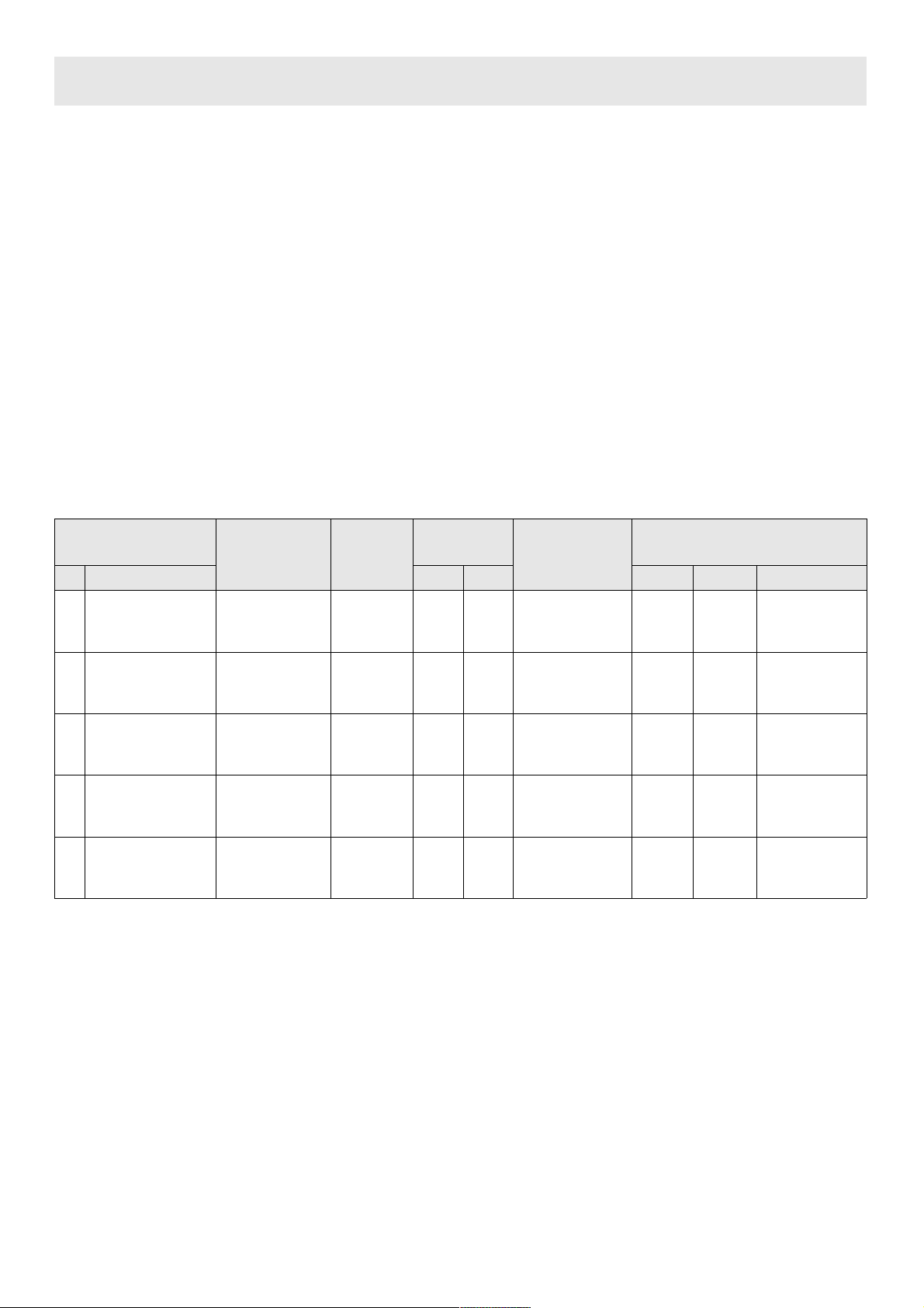
TABLE
BURNERS
GAS
NORMAL
PRESSURE
mbar
NORMAL
RATE
INJECTOR
DIAMETER
1/100 mm
NOMINAL HEAT
INPUT (W)
N°
DESCRIPTION
gr/h l/h Min. Max. E.E
Gas Burner*
1
ULTRA RAPID
(**DCC AFB)
G30 - BUTAN
G31 - PROPAN
G20 - NATURAL
28 - 30
37
20
291
286
381
100 H1
100 H1
150 Z1
1800
1800
1800
4000
4000
4000
55,9 %
2
RAPID
G30 - BUTAN
G31 - PROPAN
G20 - NATURAL
28 - 30
37
20
204
200
267
83
83
117 S
900
900
900
2800
2800
2800
58,0 %
3
SEMIRAPID
REDUCED
G30 - BUTAN
G31 - PROPAN
G20 - NATURAL
28 - 30
37
20
102
100
133
60
60
88 Z
550
550
550
1400
1400
1400
60,0 %
4
SEMIRAPID
G30 - BUTAN
G31 - PROPAN
G20 - NATURAL
28 - 30
37
20
127
125
167
65
65
97 Z
550
550
550
1750
1750
1750
63,0 %
5
AUXILIARY
G30 - BUTAN
G31 - PROPAN
G20 - NATURAL
28 - 30
37
20
73
71
95
50
50
72 X
450
450
450
1000
1000
1000
N.A.
*In accordance with Regulation No. 66/2014 EU measures for the implementation of Directive 2009/125/EC, the
performance (EEgas burner) was calculated according to EN 30-2-1 last review with the G20.
CONVERSIONS
10) REPLACING THE INJECTORS
The burners can be adapted to different types of gas by mounting injectors suited to the type of gas in
question. To do this, first remove the burner tops using a an appropriate tool. Now unscrew injector (see fig.
13 - 13/A - 13/B) and fit a injector corresponding to the utilized type of gas in its place.
To access the injector, in ultra-fast burners with DCC AFB, remove the injector cover "A" (fig. 13/B).
It is advisable to strongly tighten the injector in place.
After the injectors have been replaced, the burners must be regulated as explained in paragraphs 9. The
technician must reset any seals on the regulating or pre-regulating devices.
The envelope with the injectors and the labels can be included in the kit, or at disposal to the authorized
customer Service Centre.
For the sake of convenience, the nominal rate table also lists the heat inputs of the burners, the diameter of
the injectors and the working pressures of the various types of gas.
**DCC AFB: Air from the bottom (fig. 13/B).
Page 22
SERVICING
CABLE TYPES AND SECTIONS
ATTENTION!!!
If the power supply cable is replaced, the installer should leave the ground wire (B) longer than the
phase conductors (fig. 14) and comply with the recommendations given in paragraph 8.
In case of failure or cut in the cable, please move away
from the cable and do not touch it. Moreover the device
must be unplugged and not switched on. Call the nearest
authorized service center to fix the problem.
WARNING: MAINTENANCE MUST ONLY BE
PERFORMED BY AUTHORISED PERSONS.
22
TYPE OF
HOT PLATE
TYPE OF
CABLE
SINGLE - PHASE
POWER SUPPLY
Gas hob
H05 RR - F
Section 3 x 0,75 mm
2
Page 23
Before leaving the factory, this appliance will have been tested and regulated by expert and
specialized personnel in order to guarantee the best performances.
Any repairs or adjustments which may be subsequently required may only be carried out by qualified
personnel with the utmost care and attention.
For this reason, always contact your Dealer or our nearest After Sales Service Center whenever
repairs or adjustments are required, specifying the type of fault and the model of the appliance in your
possession.
Please also note that genuine spare parts are only available from our After Sales Service Centers and
authorized retail outlets.
The above data are printed on the data label put on the inferior part of the appliance and on the
packing label.
The above information give to the technical assistant the possibility to get fit spare parts and a
heaven-sent intervention. We suggest to fill the table below.
MARK: ........................................................................
MODEL: ......................................................................
SERIES: ......................................................................
TECHNICAL ASSISTANCE AND SPARE PARTS
Keep the Warranty Certificate or the sheet of technical
data with the Instructions Handbook during the
appliance life. It contains important technical data.
23
This appliance is marked according to the European directive 2002/96/EC on
Waste Electrical and Electronic Equipment (WEEE).
This guideline is the frame of a European-wide validity of return and recycling on
Waste Electrical and Electronic Equipment.
Page 24

24
AVERTISSEMENT:
Les enfants de moins de 8 ans ne doivent jamais s’approcher de
l’appareil sans être constamment supervisés.
L’appareil peut être utilisé par des enfants de plus de 8 ans et
par des personnes ayant des capacités physiques, sensorielles
ou mentales réduites ou des personnes dépourvues
d’expérience et de connaissances spécifiques à condition qu’il
soient supervisés ou qu’ils aient reçu des directives pour
l’utilisation de l’appareil dans des conditions de sécurité et
compris les dangers.
Les enfants ne doivent pas jouer avec l’appareil.
Les enfants ne doivent pas effectuer sans supervision les
opérations de nettoyage et d’entretien par l’utilisateur.
MATIERES:
pag.
25 description de table de cuisson
pag. 26 avertissements de sécurité importants
pag. 27 utilisation
pag. 28 nettoyage - installation
pag. 29 installation, fixation de la table de cuisson
pag. 30 installation - raccordement au gaz
pag. 31 installation, branchement eletrique, reglage robinets
pag. 32 transformation
pag. 33 entretien - regulation gaz de l’appareil
pag. 34 etiquette segnaletique
pag. 35 service apres-vente
Page 25
25
DESCRIPTION DES TABLES DE CUISSON
1 Brûleur ultrarapide (*DCC AFB) de 4000 W
2 Brûleur rapide de 2800 W
3 Brûleur semi-rapide réduit de 1400 W
4 Brûleur semi-rapide de 1750 W
5 Brûleur auxiliaire de 1000 W
7 Bouton de commande brûleur n° 1
8 Bouton de commande brûleur n° 2
9 Bouton de commande brûleur n° 3
10 Bouton de commande brûleur n° 4
11 Bouton de commande brûleur n° 5
*DCC AFB: Air du bas (fig.13/B).
Attention: cet appareil a été conçu pour un usage domestique, dans un milieu domestique et
privé.
Chaque plaque de cuisson a été conçue pour être utilisée uniquement comme appareil de
cuisson: tout autre emploi (tel que le chauffage des pièces) doit être considéré inadapté et
dangereux.
Page 26

26
AVERTISSEMENTS DE SÉCURITÉ IMPORTANTS
AVERTISSEMENTS
IMPORTANTS POUR L'UTILISATEUR
Attention: pendant le fonctionnement, le plan de
travail chauffe très fort à l’endroit de la cuisson:
garder les enfants à distance de sécurité!
● ATTENTION!
En cas de rupture du verre du plan de cuisson:
●éteindre immédiatement tous les feux et les
éléments chauffants électriques, puis mettre
l’appareil hors tension;
●ne pas toucher la surface de l’appareil;
●ne pas utiliser l’appareil.
●IMPORTANT: pour une installation parfaite, le
réglage ou la transformation de la plaque de
cuisson pour l’emploi d’autres types de gaz, il est
nécessaire de faire appel à un INSTALLATEUR
QUALIFIÉ : le non respect de cette consigne
entraîne l’annulation de la garantie.
●IMPORTANT: l’installation doit s'effectuer
conformément aux instructions du fabricant. Une
mauvaise installation peut causer des blessures
corporelles aux gens et aux animaux, ou des
dégâts matériels dont le fabricant ne peut être
tenu pour responsable.
●Si l’installation de l’appareil requiert des
modifications de l’installation électrique
domestique ou en cas d’incompatibilité entre la
prise et la fiche de l’appareil, s’adresser à du
personnel qualifié pour le remplacement. Ce
dernier devra notamment vérifier que la section
des câbles de la prise soit adaptée à la
puissance absorbée par l’appareil.
●L’utilisation d’un appareil de cuisson à gaz
produit de la chaleur et de l’humidité dans le
local où il est installé. Il faut donc assurer une
bonne aération du local sans encombrer les
ouvertures de ventilation naturelle (fig. 3) et
activer le dispositif mécanique d’aération (hotte
d’aspiration ou électro-ventilateur fig. 4 et fig. 5).
●Une utilisation intensive et prolongée de
l’appareil peut exiger une aération
supplémentaire, par exemple l’ouverture d’une
fenêtre, ou une aération plus efficace en
augmentant la puissance de l’aspiration
mécanique existante.
●Ne jamais tenter de modifier les caractéristiques
techniques du produit: cela pourrait s’avérer
dangereux.
●Si vous décidez de ne plus utiliser l’appareil (ou
de remplacer un ancien modèle) avant de le
porter à la démolition, il est recommandé de le
rendre inutilisable comme le prévoient les
réglementations en vigueur en matière de
protection de la santé et de pollution de
l'environnement.
●Pour ce faire, il faut rendre inoffensives les
parties dangereuses, spécialement pour les
enfants, qui pourraient vouloir jouer avec
l’appareil hors d’usage.
●Ne pas toucher l’appareil avec les mains ou les
pieds mouillés ou humides.
●Ne pas utiliser l’appareil avec les pieds nus.
●Le fabricant ne peut être tenu pour responsable
d’éventuels dommages imputables à des
emplois incorrects, erronés ou irraisonnables.
●Pendant le fonctionnement, ou immédiatement
après, certaines parties de la plaque de cuisson
atteignent des températures très élevées: ne pas
y toucher.
●Après avoir utilisé la plaque de cuisson, s'assurer
que l’index des boutons soit en position de
fermeture et fermer le robinet principal du conduit
de gaz ou le robinet de la bouteille.
●En cas de problèmes de fonctionnement des
robinets de gaz, appeler le Service après-vente.
●
Conserver le Certificat de Garantie, ou la fiche
technique, avec la notice d’emploi pendant toute
la durée de vie de l’appareil. Il/elle contient
d’importantes données techniques.
IMPORTANT:
Tous nos produits sont conformes aux
normes européennes et aux endements
correspondants.Le produit est donc
conforme aux exigences des Directives
européennes en vigueur en ce qui
concerne :
- la compatibilité électromagnétique (CEM) ;
- la sécurité électrique (directive basse
tension) ;
- la limitation de l'utilisation de certaines
substances dangereuses ;
- l'écoconception.
● L'appareil est conforme aux dispositions des
sous-règlemen ts pour les directiv es
européennes:
- Règlement (UE) 2016/426.
Page 27
27
1) BRULEURS
A la surface de la table, au-dessus de chaque
bouton, un schéma est imprimé en sérigraphie
indiquant le brûleur auquel il se réfère. Après avoir
ouvert le robinet du gaz ou de la bouteille de gaz,
allumez les brûleurs en procédant comme suit:
- allumage électrique automatique
Enfoncez et tournez en sens inverse horaire le
bouton co rrespondant au brûl eur à utili ser,
tournez-le sur la position Maximum (Position
9 fig. 1) puis appuyez à fond sur le bouton, le
robinet est équipé d'une échelle de 9 positions, à
chaque clic la flamme est réduite jusqu'à ce que
vous atteigniez la position de 1, c'est-à-dire
l'apport minimum de gaz.
- Allumage des brûleurs équipés d’un
thermocouple de sécurité
Pour les brûleurs munis d’un thermocouple de
sécurité, tournez en sens inverse horaire le bouton
correspondant au brûleur à utiliser, tournez-le sur la
position Maximum ( Position 9 fig. 1) jusqu’à ce que
vous sentiez un arrêt léger puis appuyez sur le
bouton. Lorsque le brûleur est allumé, maintenez le
bouton enfoncé pendant 10 secondes environ.
Suivez ensuite les instructions pour utiliser le
robinet comme expliqué ci-dessus.
Pour tous les modèles, en cas d’extinction
accidentelle des flammes, fermez le bouton du
brûleur et ne tentez pas de le rallumer pendant au
moins 1 min.
Utilisation des brûleurs
Pour obtenir le meilleur rendement avec une
consommation minimum de gaz, n’oubliez ce qui
suit:
- utilisez pour chaque brûleur des casseroles
appropriées (voir le tableau suivant et la fig. 2).
- Lorsque le point d’ébullition est atteint, tournez le
bouton sur Minimum ( Posiition 1, fig. 1).
- Utilisez toujours des casseroles avec un
couvercle.
- Utilisez uniquement des récipients à fond plat.
AVERTISSEMENTS:
- l’allumage des brûleurs avec un thermocouple
de sécurité n’est possible que lorsque le bouton
se trouve sur la position Maximum (Position 9,
fig. 1).
- En cas de coupure de courant, vous pouvez
allumer les brûleurs avec des allumettes.
- Durant l’utilisation des brûleurs, ne laissez pas
l’appareil sans surveillance et éloignez les
enfants. En particulier, assurez-vous que les
poignées des casseroles sont correctement
orientées et surveillez la cuisson des aliments
contenant des huiles et des graisses car elles
sont facilement inflammables.
- N’utilisez pas de spray à proximité de l’appareil
lorsqu’il est en fonction.
- Evitez d’utiliser des casseroles dépassant du
bord de la table de cuisson.
UTILISATION
Brûleurs
Ø Casseroles cm
Ultrarapide 24 ÷ 26
Rapide
20 ÷ 22
Semi-rapide réduit 16 ÷ 18
Semi-rapide 16 ÷ 18
Auxiliaire 10 ÷ 14
Position fermée
FIG. 1
9) Position de
distribution maximale
de gaz
1) Position de
distribution minimale
de gaz
Page 28
28
INSTALLATION
NETTOYAGE
ATTENTION:
avant toute opération de nettoyag e,
débranchez l’appareil du réseau du gaz et du
réseau électrique.
2) PLAN DE TRAVAIL
Pour que la surface en verre soit toujours brillante,
il est très important de la laver après chaque
utilisation à l’eau savonneuse tiède, de la rincer et
de la sécher.
Lavez de la même manière les grilles émaillées,
les chapeaux émaillés “A”, “B” et “C” et la tête des
brûleurs “T” (voir fig. 6 - 6/A) et nettoyez les
bougies d’allumage “AC” ainsi que les capteurs
des thermocouples “TC” (voir fig. 6).
Nettoyez-les délicatement avec une petite brosse
en nylon comme indiqué (voir fig. 6/B) et laisser
sécher complètement. Ne les lavez pas au lavevaisselle. Procédez au nettoyage lorsque la table
et les composants ne sont pas chauds, en évitant
les éponges métalliques, les produits abrasifs en
poudre ou les sprays corrosifs.
Evitez que le vinaigre, le café, le lait, l’eau salée
et le jus de citron ou de tomate ne restent trop
longtemps au contact des surfaces.
AVERTISSEMENTS:
en remontant les éléments, suivez les
recommandations ci-après:
- vérifiez que les fentes des têtes des brûleurs
“T” (fig. 6) ne sont pas obstruées par des
corps étrangers.
- S’assurer que les chapeaux émaillés “A”, “B”
et “C” (fig. 6 - 6/A ) sont c orrectement
positionnés sur la tête du brûleur. C’est le
cas lorsque le chapeau positionné sur la tête
est parfaitement stable.
- Les grilles doivent être placés dans les pions
de centrage appropriées (ou sur le profil
d'aluminium si présente). Vérifier la parfait
stabilité.
- Si la manœuvre d’ouverture et de fermeture
d’un robinet devient difficile, ne forcez pas,
mais demandez au plus vite l’intervention du
service après-vente.
- Ne nettoyez pas l’appareil au jet de vapeur.
- Pour prévenir les difficultés d’allumage,
nettoyez pér iodiquement les bougies
d’allumage (céramique et électrode) ainsi que
les thermocouples.
INFORMATIONS TECHNIQUES POUR
L’INSTALLATEUR
L’installati on, tous le s réglage s, les
transformations et les opérations d’entretien
indiquées da ns cette partie doivent être
exclusivement effectués par du personnel
qualifié.
L’appareil doit être convenablement installé,
selon les normes en vigueur et les instructions
du fabricant.
Une installation erronée peut provoquer des
dégâts aux personnes, aux animaux ou aux
choses, déchargeant le Constructeur de toute
responsabilité.
Les dispositifs de sécurité ou de réglage
automatique des appareils pendant la durée de
vie de l’insta llation pour ront être
exclusivement modifiés par le constructeur ou
par le fournisseur dûment autorisé.
3) MISE EN PLACE DE LA TABLE DE
CUISSON
Après avoir enlevé l’emballage externe et les
emballages internes des différents éléments
mobiles, contrôlez l’intégrité de la table. En cas de
doute, n’utilisez pas l’appareil et adressez-vous à
du personnel qualifié.
Ne laissez pas les éléments de l’emballage
(carton, sachets, polystyrène expansé, clous,
etc.) à la portée des enfants car ils sont une
source potentielle de danger.
Réalisez dans le dessus du meuble à éléments,
une ouverture pour l’encastrement ayant les
dimensions indiquées dans la fig. 7, en respectant
les dimensions critiques de l’espace d’installation
de l’appareil (voir fig. 7 et 8).
L’appareil doit appartenir à la classe 3 et sera
donc sujet à toutes les prescriptions prévues
par les normes en vigueur pour ces appareils.
Remarque: l’em ploi constant
pourrait modifier la couleur originale à
hauteur des brûl eurs, en raison des
températures élevées.
ATTENTION: ne pa s poser le verre
directement sur le meuble, mais le fond de la
table de cuisson.
Page 29

29
INSTALLATION INSTALLATION
4) FIXATION DE LA TABLE DE CUISSON
INSTALLATION TYPE: A
La table est équipée d’un joint spécial empêchant
toute infiltration de liquide dans le meuble. Pour
appliquer correcteme nt ce joint, respec tez
scrupuleusement les instructions suivantes:
- enlevez toutes les parties mobiles de la table de
cuisson.
- Coupez le joint en 4 parties de la longueur
nécessaire de manière à le positionner sur les 4
bords du verre.
- Retournez la table et positionnez correctement le
côté adhésif du joint «E» (fig. 11/A) sous le bord
du verre de manière à ce que le côté externe du
joint coïn cide parfaitement ave c le bord
périmétral externe du verre. Les extrémités des
bandes doivent coïncider sans se chevaucher.
- Fait es adhérer le joint au ve rre de façon
uniforme et sûre, en le pressant avec les doigts.
- Plac ez les crochets dans leu rs positions
respectives en utilisant comme référence le trou
1 pour les positions cote (fig. 9) et le trou 2 pour
les positions arrière (fig. 10).
- Fixez les crochets « G « avec les vis « F » (fig.
9/A pour cote, et 10/A pour arrière).
- Placez la table de cuisson dans le trou de’
armoire de la cuisine avec une petite pression
pour surmonter la résistance des crochets (fig.
9/B pour cote, fig. 10/B pour arrière). Voir le
schéma page 11.
- Pour éviter tout contact accidentel avec la
surface de la boîte de la table surchauffée durant
son fonctionnement, appliquez une séparation
en bois bloquée par des vis à une distance
minimale de 70 mm du dessus (fig. 7).
4/A) FIXATION DE LA TABLE DE CUISSON
INSTALLATION TYPE: B
La table est équipée d’un joint spécial empêchant
toute infiltration de liquide dans le meuble. Pour
appliquer correcteme nt ce joint, respec tez
scrupuleusement les instructions suivantes:
- enlevez toutes les parties mobiles de la table de
cuisson.
- Coupez le joint en 4 parties de la longueur
nécessaire de manière à le positionner sur les 4
bords du verre.
- Retournez la table et positionnez correctement le
côté adhésif du joint «E» (fig. 11/A) sous le bord
du verre de manière à ce que le côté externe du
joint coïn cide parfaitement ave c le bord
périmétral externe du verre. Les extrémités des
bandes doivent coïncider sans se chevaucher.
- Fait es adhérer le joint au ve rre de façon
uniforme et sûre, en le pressant avec les doigts.
- Placez la cuisinière dans le trou fait dans le
cabinet et le fixer avec des vis "F" crochets "G"
(voir fig. 11).
- Pour éviter tout contact accidentel avec la
surface de la boîte de la table surchauffée durant
son fonctionnement, appliquez une séparation
en bois bloquée par des vis à une distance
minimale de 70 mm du dessus (fig. 7).
Attention: Ne laissez pas le verre (A) était directement sur le plan
de travail. il est le étagère inférieure “carter” (B) qui doit être en
contact avec le plan de travail (voir fig. 11/B).
Page 30

30
INSTALLATION
PRESCRIPTIONS IMPORTANTES
POUR L'INSTALLATION
Information pour l'installateur: les parois
latérales éventuelles ne doivent pas dépasser
en hauteur la table de cuisson. En outre, la
paroi postérieure ainsi qu e les surfaces
adjacentes et environnantes doivent résister à
une temperature de 90 °C.
Le produit collant qui unit le laminé plastique
au meuble doit résister à des températures
supérieures à 150 °C pour év iter le
décollement du revêtement.
L'installation de l'appareil doit être conforme
aux normes en vigueur.
Cet appareil n'est pas raccordé à un dispositif
d'évacuation des produits de la combustion. Il
doit donc être raccordé conformément aux
règles d'installation mentionnées ci-dessus. Il
faudra prêter une attention particulière aux
dispositions applicabl es en matière de
ventilation et d'aération.
5) AERATION DE LA PIECE
Le local où est installé l’appareil doit être ventilé
en p ermanence po ur ga rantir le bon
fonctionnement de l’appareil. La quantité d’air
nécessaire est celle utilisée par la combustion des
gaz et par la ventilation de la pièce dont le volume
devra être au moins de 20 m3. L’aération naturelle
directe doit être assurée par des ouvertures
permanentes d’une section minimum de 100 cm
2
(voir fig. 3) aménagées sur les parois extérieures
de la pièce. Il ne doit pas être possible d’obstruer
ces ouvertures.
L’aération indirecte est également admise en
prélevant l’air d’un local adjacent. Dans ce cas
respecter formellement les normes en vigueur.
ATTENTION: si les brûleurs de la table de
cuisson sont dépourvus du thermocouple de
sécurité, l’ouverture de ventilation doit avoir
une surface minimale de 200 cm2.
6) EMPLACEMENT ET EVACUATION
DES PRODUITS DE LA COMBUSTION
Les tables de cuisson doivent toujours évacuer les
produits de la combustion dans des hottes reliées à
des conduits ou débouchant directement à
l’extérieur (voir fig. 4). Lorsqu’il n’est pas possible
de monter une hotte, vous pouvez utiliser un
ventilateur installé sur la fenêtre ou sur une paroi
donnant vers l’extérieur, dans le respect des
normes en vigueur sur l’aération de la pièce. Ce
dispositif sera mis en marche en même temps que
l’appareil (voir fig. 5).
7) RACCORDEMENT AU GAZ
Avant de raccorder l'appareil, s'assurer que les
données figurant sur l'étiquette signalétique
appliquée sur la partie inférieure du caisson
sont compatibles avec celles du réseau de
distribution du gaz.
Une étiquette imprimée de ce livret ainsi qu'une
étiquette appliquée sur la partie inférieure du
caisson indiquent les conditions de réglage de
l'appareil: type de gaz et pression d'exercice.
Quand le gaz est distribué par une canalisation,
l'appareil doit être raccordé à l'installation d'arrivée
du gaz selon la norme:
●
soit au moyen d'un tuyau métallique rigide en acier,
dont les jonctions doivent être réalisées au moyen
de raccords filetés conformément à la norme en
vigueur.
●
Soit au moyen d'un tuyau de cuivre, dont les
jonctions doivent être réalisées au moyen de
raccords à garniture mécanique.
●
Soit au moyen d'un t uyau flexibl e en acier
inoxydable à paroi continue, avec une extension
maximale de 2 mètr es et des garniture s
d'étanchéité conforme aux normes.
Lorsque le gaz est directement distribué à
partir d'une bouteille, l'appareil, alimenté par un
régulateur de pression, doit être raccordé:
●
soit au moyen d'un tuyau de cuivre, dont les
jonctions doivent être réalisées au moyen de
raccords à garniture mécanique.
●
Soit au moyen d'un t uyau flexibl e en acier
inoxydable à paroi continue, avec une extension
maximale de 2 mètr es et des garniture s
d'étanchéité conforme aux normes. Il est conseillé
d'appliquer sur le tuyau flexible l'adaptateur spécial,
couramme nt vendu dans le commerce, pour
faciliter le raccordement à l'embout du régulateur
de pression monté sur la bouteille.
●
Soit par tube souple en caoutchouc d'une lungueur
allant de 400 à 1500 mm, fixé solidement à
l'embout par un collier de sécurité.
À l'extrémité de raccordement, vérifiez le gasproof
en utilisant une solution de savon, jamais une
flamme.
AVERTISSEMENTS:
- le raccord d'entrée du gaz de l'appareil est
fileté 1/2" gaz conique mâle conformément
aux normes EN 10226.
- Le tuyau flexible ou le tube souple doit être
installé de manière à ne pas être en contact
avec des parties mobiles du mo dule
encastrable (par exemple des tiroirs) et ne
doit pas traverser des casiers pouvant être
remplis.
Page 31
31
8) BRANCHEMENT ELECTRIQUE
Le raccordement électrique doit être réalisé
conformément aux normes et aux lois en
vigueur.
- La tension corresponde à la valeur indiquée sur
la plaquette signalétique et que la section des
câbles de l’insta llation élec trique puiss e
supporter la charge, indiquée elle aussi sur la
plaquette.
- Avant de réaliser le raccordement, vérifiez que la
prise ou l’ installation est mun ie d’un
raccordement efficace à la terre selon les
normes et les lois actuellement en vigueur. On
décline tout e respon sabilité en cas non
observation de ces dispositions.
Quand le r accordement au réseau
d’alimentation est effectué par l’intermédiaire
d’une prise:
- s’il en est dépourvu, appl iquez au câb le
d’alimentation «C» (voir fig. 8/A) une fiche
normalisée indiquée pour la charge figurant sur
l’étiquette signalétique. Branchez les fils d’après
le schéma de la fig. 8/A en respectant les
correspondances suivantes:
lettre L (phase) = fil marron;
lettre N (neutre) = fil bleu;
symbole de la terre = fil vert-jaune.
- Le câble d’alimentation doit être positionné de
manière à ce qu’il n’atteigne jamais, en aucun
point, la température de 90 °C.
- N’ut ilisez pas, p our le raccordement des
réducteurs, des adaptateurs ou des shunts car
ils pourraient provoquer des faux-contacts
entraînant des surchauffes dangereuses.
- La prise doit être accessible au terme de
l’encastrement.
Quand le raccordement est directement réalisé
sur le réseau électrique:
- interposez entre l’appareil et le réseau un
interrupteur omnipolaire, dimensionné suivant la
charge de l’appareil , selon les nor mes
d’installation en vigueur.
- N’oubliez pas que le câble de terre ne doit pas
être interrompu par l’interrupteur.
- Pour un maximum de sécurité, le raccordement
électrique peut également être protégé par un
interrupteur différentiel à haute sensibilité.
On recommande vivement de fixer le fil de terre
vert-jaune à une installation de terre efficiente.
Avant tout travail sur la partie électrique de
l'appareil, il faut absolument la débrancher du
secteur.
Avant tout réglage, mettez l’appareil hors
tension.
Au terme des réglages ou des préréglages, les
éventuels scellages doivent être rétablis par le
technicien.
Le réglage de l’air primaire n’es t pas
nécessaire sur nos brûleurs.
9) ROBINETS
Réglage du «Minimum»:
- allumez le brûleur et tournez le bouton sur le
Minimum (petite flamme fig. 1).
- retirer le bouton «M» (fig. 12 et 12/A) du robinet
fixé par une simple pression sur le pivot de celuici. Le régulateur de la capacité minimale peut se
trouver: sur le côté du robinet (fig. 12) ou à
l’intérieur du pivot. En tous les cas, pour le
réglage, on y accède en insérant un petit
tournevis «D» sur le côté du robinet (fig. 12), ou
dan le trou «C» à l’intérieur du pivot du robinet
(fig. 12/A).
- tourner le régulateur vers la droite ou vers la
gauche en réglant de façon appropriée la
flamme dans la position de capacité réduite.
Il est recommandé de ne pas exagérer avec le
«Minimum»: la petite flamme doit être stable et
constante.
Remonter correctement les différents composants.
On rappelle que le susdit réglage ne doit être
effectué qu’avec les brûleurs fonctionnant au
G20, tandis qu’avec les brûleurs fonctionnant
au G30 ou au G31 la vis doit être bloquée à
fond (en sens horaire).
INSTALLATION REGLAGES
ROBINETS LUBRIFICATION
Si un robinet étant bloqué, ne forcez
pas et demander de l'aide technique.
Page 32
32
TABLEAU
BRULEURS
GAZ
PRESSION
D’EXERCICE
mbar
DEBIT
THERMIQUE
DIAMETRE
BUSE
1/100 mm
DEBIT
THERMIQUE
(W)
N°
DESCRIPTION
gr/h l/h Min. Max. E.E
GazBruleurs*
1
ULTRARAPIDE
(**DCC AFB)
G30 - BUTANE
G31 - PROPANE
G20 - NATURAL
28 - 30
37
20
291
286
381
100 H1
100 H1
150 Z1
1800
1800
1800
4000
4000
4000
56,0 %
2
RAPIDE
G30 - BUTANE
G31 - PROPANE
G20 - NATURAL
28 - 30
37
20
204
200
267
83
83
117 S
900
900
900
2800
2800
2800
58,0 %
3
SEMI-RAPIDE
RÉDUIT
G30 - BUTANE
G31 - PROPANE
G20 - NATURAL
28 - 30
37
20
102
100
133
60
60
88 Z
550
550
550
1400
1400
1400
60,0 %
4
SEMI-RAPIDE
G30 - BUTANE
G31 - PROPANE
G20 - NATURAL
28 - 30
37
20
127
125
167
65
65
97 Z
550
550
550
1750
1750
1750
63,0 %
5
AUXILIAIRE
G30 - BUTANE
G31 - PROPANE
G20 - NATURAL
28 - 30
37
20
73
71
95
50
50
72 X
450
450
450
1000
1000
1000
N.A.
*Conformément au règlement n ° 66/2014 mesures de l'UE pour la mise en œuvre de la directive
2009/125/CE, le (brûleur de EEgas) de performance a été calculée selon la norme EN 30-2-1
dernier examiner avec le G20.
TRANSFORMATIONS
10) REMPLACEMENT DES BUSES
Les brûleurs sont adaptables aux différents gaz en montant les buses correspondant au gaz d’utilisation.
Pour cela, enlevez les têtes des brûleurs et avec au outil approprié, dévissez la buse (voir fig. 13 - 13/A 13/B) et remplacez-la par une buse correspondant au gaz d’utilisation.
Pour accéder à l'injecteur, dans les brûleurs ultra-rapides avec DCC AFB, retirez le capuchon
d'injecteur "A" (fig. 13/B).
On conseille de bloquer la buse avec énergie.
Après avoir effectué les susdits remplacements, le technicien devra régler les brûleurs tel qu’on le décrit
au paragraphe 9, sceller les éventuels organes de réglage ou de préréglage et remplacer sur l’appareil
l’étiquette correspondant au nouveau réglage du gaz effectué sur l’appareil. Cette étiquette se trouve
dans le sachet des buses de rechange.Pour aider l’installateur, nous indiquons dans le tableau ci-
après les débits, les débits thermiques des brûleurs, le diamètre des buses et la pression
d’exercice pour les différents gaz.
**DCC AFB: Air du bas (fig. 13/B).
Page 33

33
ENTRETIEN
TYPES ET SECTIONS DES CABLES D’ALIMENTATION
TYPE DE TABLE TYPE DE TABLE
ALIMENTATION
MONOPHASE
ATTENTION !!!
En cas de remplacement du câble d’alimentation, l’installateur devra garder le conducteur de terre
«B» le plus long par rapport aux conducteurs de phase (fig. 14) et il devra respecter les
avertissements indiqués au paragraphe 8.
Table de cuisson au gaz H05 RR-F Section 3 x 0.75 mm
2
En cas de panne ou de couper le câble, s'il vous plaît
s'éloigner du câble et ne pas toucher. En outre, le
dispositif doit être débranché et pas allumé. Appelez
le centre de service agréé le plus proche pour
résoudre le problème.
ATTENTION: L’ENTRETIEN DOIT ÊTRE CONFIÉ
EXCLUSIVEMENT À DU PERSONNEL AGRÉÉ.
DONNEES TECHNIQUES DE LA
RÉGULATION GAZ DE L’APPAREIL
En cas d’adaptation de la plaque de cuisson à un
autre type de gaz, procédez comme décrit dans les
instructions concernant l’installation et l’utilisation et
remplacer l’étiquette sur le fond par celle fournie dans le
sac des pièces de rechange.
Page 34
34
CARACTERISTIQUES TECHNIQUES REPORTEES
SUR L’ETIQUETTE SEGNALETIQUE
ΣQn
NATUREL
G20
20 mbar
ΣQn
BUTANO
G30
28 - 30 mbar
ΣQn
PROPANO
G31
37 mbar
TENSION
V~
EEgashob
CATÉGORIE = II2H3+ FREQUENCE 50 - 60 Hz
4.0 kW 291 gr/h 286 gr/h 220-240 56,0 %
3.80 kW 276 gr/h 271 gr/h 220-240 58,0 %
7.80 kW 567 gr/h 557 gr/h 220-240 57,0 %
6.95 kW 505 gr/h 496 gr/h 220-240 60,3 %
9.55 kW 694 gr/h 682 gr/h 220-240 58,3 %
10.95 kW 796 gr/h 782 gr/h 220-240 59,30 %
10.95 kW
796 gr/h 782 gr/h 220-240 59,30 %
10.95 kW
796 gr/h 782 gr/h 220-240 59,30 %
12.70 kW
923 gr/h 907 gr/h 220-240 59,40 %
Page 35

35
Avant de quitter l’usine, cet appareil a été testé et mis à point par du personnel expert et spécialisé, de
manière à garantir les meilleurs résultats de fonctionnement.
Les pièces de rechange originales sont disponibles uniquement dans nos Centres d’Assistance
Technique et dans les magasins autorisés.
Toute réparation ou mise à point nécessaire par la suite doit être effectuée avec le plus grand soin et
la plus grande attention par du personnel qualifié.
C’est la raison pour laquelle nous recommandons de toujours vous adresser au Concessionnaire qui
a effectué la vente ou à notre Centre d’Assistance le plus proche en indiquant la marque, le modèle,
le numéro de série et le type de problème de votre appareil. Les données correspondantes sont
poinçonnées sur l’étiquette signalétique appliquée sur la partie inférieure de l’appareil et sur l’étiquette
de la boîte d’emballage.
Ces informations permettent au technicien de se munir des pièces de rechange adéquates et de
garantir par conséquent une intervention immédiate et précise. On conseille d’indiquer ces données
ci-après de manière à les avoir toujours à portée de la main :
MARQUE: .................................................
MODELE: .................................................
SERIE: ......................................................
SERVICE APRES-VENTE ET PIECES DE RECHANGE
Conserver le Certificat de Garantie, ou la fiche
technique, avec la notice d’emploi pendant toute
la durée de vie de l’appareil. Il/elle contient
d’importantes données techniques.
Page 36
Cet appareil est marqué selon la directive européenne 2002/96/CE relative aux appareils
électriques et électroniques usagés (waste electrical and electronic equipment - WEEE).
La directive définit le cadre pour une reprise et une récupération des appareils usagés
applicables dans les pays de la CE.
Page 37
ﻝﺑﻗ ﺓﺭﺩﺎﻐﻣ ،ﻊﻧﺻﻣﻟﺍ ﻥﻭﻛﻳﺳ ﺍﺫﻫ ﺯﺎﻬﺟﻟﺍ ﺩﻗ ﻊﺿﺧ ﺭﺎﺑﺗﺧﻼﻟ ﻡﻳﻅﻧﺗﻟﺍﻭ ﻰﻠﻋ ﺩﻳ ﻡﻗﺎﻁ ﺭﻳﺑﺧ ﺹﺻﺧﺗﻣﻭ ﻥﺎﻣﺿﻟ ﻝﺿﻓﺃ ءﺍﺩﺃ .
ﻱﺃ ﺕﺎﺣﻼﺻﺇ ﻭﺃ ﺕﻼﻳﺩﻌﺗ ﺩﻗ ﺎﻬﺑﻠﻁﺗﻳ ﺯﺎﻬﺟﻟﺍ ﺩﻌﺑ ،ﻙﻟﺫ ﺏﺟﻳ ﻥﺃ ﺫﻔﻧُﺗ ﻁﻘﻓ ﻥﻋ ﻖﻳﺭﻁ ﺩﺍﺭﻓﺃ ﻥﻳﻠﻫﺅﻣ ﻊﻣ ﻲﺧﻭﺗ ﻰﺻﻗﺃ ﺕﺎﺟﺭﺩ ﺹﺭﺣﻟﺍ ﻩﺎﺑﺗﻧﻻﺍﻭ.
ﺍﺫﻬﻟ ،ﺏﺳﻟﺍ ﻝﺻﺗﺍ ًﺎﻣﺋﺍﺩ ﺭﺟﺎﺗﻟﺎﺑ ﻱﺫﻟﺍ ﺕﻳﺭﺗﺷﺍ ﻪﻧﻣ ﻭﺃ ﺏﺭﻗﺄﺑ ﺯﻛﺭﻣ ﺕﺎﻣﺩﺧﻟ ﺎﻣ ﺩﻌﺑ ﻊﻳﺑﻟﺍ ﺎﻣﻠﻛ ﺕﻧﺎﻛ ﻙﺎﻧﻫ ﺔﺟﺎﺣ ءﺍﺭﺟﻹ ﺕﺎﺣﻼﺻﺇ ﻭﺃ ،ﺕﻼﻳﺩﻌﺗ ﻊﻣ
ﺩﻳﺩﺣﺗ ﻉﻭﻧ ﻝﻁﻌﻟﺍ ﻝﻳﺩﻭﻣﻭ ﺯﺎﻬﺟﻟﺍ ﻱﺫﻟﺍ ﻙﺗﺯﻭﺣﺑ .
ﻰﺟﺭُﻳ ًﺎﺿﻳﺃ ﺔﻅﺣﻼﻣ ﻥﺃ ﻊﻁﻗ ﺭﺎﻳﻐﻟﺍ ﺔﻳﻠﺻﻷﺍ ﺓﺭﻓﻭﺗﻣ ﻁﻘﻓ ﻯﺩﻟ ﺯﻛﺍﺭﻣ ﺕﺎﻣﺩﺧ ﺎﻣ ﺩﻌﺑ ﻊﻳﺑﻟﺍ ﺫﻓﺎﻧﻣﻭ ﻊﻳﺑﻟﺍ ﺔﺋﺯﺟﺗﻟﺎﺑ ﺓﺩﻣﺗﻌﻣﻟﺍ .
ﺕﺎﻧﺎﻳﺑﻟﺍ ﺔﻘﺑﺎﺳﻟﺍ ﺔﻋﻭﺑﻁﻣ ﻰﻠﻋ ﻖﺻﻠﻣ ﺕﺎﻧﺎﻳﺑ ﻰﻠﻋ ءﺯﺟﻟﺍ ﻲﻠﻔﺳﻟﺍ ﻰﻠﻋ ﺯﺎﻬﺟﻟﺍ ﻰﻠﻋﻭ ﻖﺻﻠﻣ ﺓﻭﺑﻌﻟﺍ .
ﺢﻧﻣﺗ ﺕﺎﻣﻭﻠﻌﻣﻟﺍ ﺔﻘﺑﺎﺳﻟﺍ ﺩﻋﺎﺳﻣﻠﻟ ﻲﻧﻘﺗﻟﺍ ﺔﻳﻧﺎﻛﻣﺇ ﻝﻭﺻﺣﻟﺍ ﻰﻠﻋ ﻊﻁﻗ ﺭﺎﻳﻐﻟﺍ ﺔﺑﺳﺎﻧﻣﻟﺍ ﺕﻼﺧﺩﺗﻟﺍﻭ ﺓﻭﺟﺭﻣﻟﺍ .ﺡﺭﺗﻘﻧ ﺊﻠﻣ ﻝﻭﺩﺟﻟﺍ ﻩﺎﻧﺩﺃ .
ﺔﻣﻼﻌﻟﺍ ﺓﺯﻳﻣﻣﻟﺍ ﻖﻳﻠﻌﺗﻟﺍﻭ : ........................................................................
ﻝﻳﺩﻭﻣﻟﺍ : ......................................................................
ﻡﻗﺭ ﻝﺳﻠﺳﻣﻟﺍ : ......................................................................
ﺔﻳﻧﻘﺗ ﺔﻣﺎﻫ .
ﻅﻔﺗﺣﺍ ﺓﺩﺎﻬﺷﺑ ﻥﺎﻣﺿﻟﺍ ﻭﺃ ﺔﺣﻔﺻ ﺕﺎﻧﺎﻳﺑﻟﺍ ﺔﻳﻧﻘﺗﻟﺍ ﻊﻣﺏﻳﺗﻛ ﺕﺎﻣﻳﻠﻌﺗﻟﺍ ﻝﻼﺧ ﺓﺎﻳﺣ ﺯﺎﻬﺟﻟﺍ . ﺙﻳﺣ ﻱﻭﺗﺣﻳ ﻰﻠﻋ ﺕﺎﻧﺎﻳﺑ
ﻡﺗ ﺯﻳﻳﻣﺗ ﺍﺫﻫ ﺯﺎﻬﺟﻟﺍ ًﺎﻘﻓﻭ ﻪﻳﺟﻭﺗﻠﻟ ﻲﺑﻭﺭﻭﻷﺍ 2002/96/EC ﻥﺄﺷﺑ ﺕﺎﻳﺎﻔﻧ ﺕﺍﺩﻌﻣﻟﺍ ﺔﻳﺋﺎﺑﺭﻬﻛﻟﺍ ﺔﻳﻧﻭﺭﺗﻛﻟﻻﺍﻭ .
ﺩﻌﻳ ﺍﺫﻫ ﻪﻳﺟﻭﺗﻟﺍ ًﺍﺭﺎﻁﺇ ﺔﻳﺣﻼﺻﻟ ﺓﺩﺎﻋﻹﺍ ﺓﺩﺎﻋﺇﻭ ﺭﻳﻭﺩﺗﻟﺍ ﺔﻘﻠﻌﺗﻣﻟﺍ ﺕﺎﻳﺎﻔﻧﺑ ﺕﺍﺩﻌﻣﻟﺍ ﺔﻳﺋﺎﺑﺭﻬﻛﻟﺍ ﺔﻳﻧﻭﺭﺗﻛﻟﻻﺍﻭ .
Page 38
22
ﺔﻧﺎﻳﺻﻟﺍ
ﻊﻁﺎﻘﻣﻭ ﻉﺍﻭﻧﺃ ﺕﻼﺑﺎﻛﻟﺍ
ﺔﺣﻭﻟ ﻉﻭﻧ
ﻥﻳﺧﺳﺗﻟﺍ
ﺯﺎﻐﻟﺎﺑ ﻝﻣﻌﻳ ﺩﻗﻭﻣ
ﻝﺑﺎﻛﻟﺍ ﻉﻭﻧ
H05 RR - F
ﺭﻭﻁﻟﺍ ﻱﺩﺎﺣﺃ ﺔﻗﺎﻁ ﺭﺩﺻﻣ
2
ﻊﻁﻘﻣﻟﺍ3 ×0.75 ﻡﻣ
!!!ﻪﻳﺑﻧﺗ
ﺍﺫﺇ ﻝﺩﺑﺗﺳُﺍ ﻝﺑﺎﻛ ﺭﺩﺻﻣ ،ﺔﻗﺎﻁﻟﺍ ﺏﺟﻳ ﻰﻠﻋ ﻡﺋﺎﻘﻟﺍ ﻰﻠﻋ ﺏﻳﻛﺭﺗﻟﺍ ﻙﺭﺗ ﻙﻠﺳﻟﺍ ﻲﺿﺭﻷﺍ ) ﺏ (ﻝﻭﻁﺃ ﻥﻣ ﺕﻼﺻﻭﻣ ﺔﻠﺣﺭﻣﻟﺍ ) ﻝﻛﺷﻟﺍ 14 (ﻝﺎﺛﺗﻣﻻﺍﻭ ﺕﺎﻳﺻﻭﺗﻠﻟ
ﺔﺟﺭﺩﻣﻟﺍ ﻲﻓ ﺓﺭﻘﻔﻟﺍ 8 .
ﺭﻳﺫﺣﺗ: ﺏﺟﻳ ءﺍﺭﺟﺇ ﻝﺎﻣﻋﺃ ﺔﻧﺎﻳﺻﻟﺍ ﻥﻣ
ﻲﻓ ﺔﻟﺎﺣ ﻕﺎﻔﺧﻹﺍ ﻭﺃ ﺩﻭﺟﻭ ﻊﻁﻗ ﻝﺑﺎﻛﻟﺎﺑ ﻰﺟﺭُﻳﺩﺎﻌﺗﺑﻻﺍﻥﻋ ﻝﺑﺎﻛﻟﺍ ﻡﺩﻋﻭ ﻪﺳﻣﻟ ﺎﻣﻛ ﺏﺟﻳ
ﻉﺯﻧ ﺱﺑﺎﻗ ﺯﺎﻬﺟﻟﺍ ﻲﺋﺎﺑﺭﻬﻛﻟﺍ ﻡﺩﻋﻭ ﻪﻠﻳﻐﺷﺗ .ﻝﺻﺗﺍ ﺏﺭﻗﺄﺑ ﺯﻛﺭﻣ ﺕﺎﻣﺩﺧ ﺩﻣﺗﻌﻣ ﺡﻼﺻﻹ ﺔﻠﻛﺷﻣﻟﺍ.
Page 39
21
(ﺕﺍﻭ)
ﻝﺳ
ﻲﻌﻳﺑﻁ
ﻲﻌﻳﺑﻁ
ﻲﻌﻳﺑﻁ
ﻲﻌﻳﺑﻁ
ﻲﻌﻳﺑﻁ
ﺕﻼﻳﻭﺣﺗﻟﺍ
ﻝﺍﺩﺑﺗﺳﺍ
ﻥﻗﺎﺣﻣﻟﺍ
10 (
ﻥﻛﻣﻳ ﺔﻣءﺍﻭﻣ ﻥﻭﻳﻋ ﻥﻳﺧﺳﺗﻟﺍ ﻊﻣ ﻉﺍﻭﻧﺃ ﺯﺎﻏ ﺔﻔﻠﺗﺧﻣ ﺏﻳﻛﺭﺗﺑ ﻥﻗﺎﺣﻣ ﺔﺑﺳﺎﻧﻣ ﻉﻭﻧﻟ ﺯﺎﻐﻟﺍ ﺏﻭﻠﻁﻣﻟﺍ . ﺫﻳﻔﻧﺗﻟ ﻙﻟﺫ ﻝﺻﻓﺍ ًﻻﻭﺃ ﻡﻣﻗ ﻥﻭﻳﻋ ﻥﻳﺧﺳﺗﻟﺍ ﺡﺎﺗﻔﻣﺑ ﻁﺑﺭﻟﺍ "B ."
ﻙﻓ ﻥﻘﺣﻣﻟﺍ ﻥﻵﺍ ) ﺭﻅﻧﺍ ﻝﻛﺷﻟﺍ 13 ﻭ13 / ﺃ ﻭ- 13 / ﺏ (ﺕﺑﺛﻭ ﻥﻘﺣﻣ ﻖﻔﺗﻣ ﻊﻣ ﻉﻭﻧﻟﺍ ﻡﺩﺧﺗﺳﻣﻟﺍ ﻥﻣ ﺯﺎﻐﻟﺍ ﻲﻓ ﻪﻌﺿﻭﻣ .
ﻝﻭﺻﻭﻠﻟ ﻰﻟﺇ ﻥﻘﺣﻣﻟﺍ ﻲﻓ ﻥﻭﻳﻋ ﻥﻳﺧﺳﺗﻟﺍ ﺔﻘﺋﺎﻓ ﺔﻋﺭﺳﻟﺍ ﻊﻣ DCC AFB، ﻉﺯﻧﺍ ءﺎﻁﻏ ﻥﻘﺣﻣﻟﺍ"A) "ﻝﻛﺷﻟﺍ 13/ ﺏ .(
ﺢﺻﻧُﻳ ﻡﺎﻛﺣﺈﺑ ﺕﻳﺑﺛﺗ ﻥﻘﺣﻣﻟﺍ ﻲﻓ ﻪﻌﺿﻭﻣ .
ﺩﻌﺑ ﻝﺍﺩﺑﺗﺳﺍ ﻥﻗﺎﺣﻣﻟﺍ ﺏﺟﻳ ﻁﺑﺿ ﻥﻭﻳﻋ ﻥﻳﺧﺳﺗﻟﺍ ﺎﻣﻛ ﻭﻫ ﺢﺿﻭﻣ ﻲﻓ ﺓﺭﻘﻔﻟﺍ 9 .ﺏﺟﻳ ﻰﻠﻋ ﻲﻧﻔﻟﺍ ﻥﺃ ﺓﺩﺎﻋﺇ ﻁﺑﺿ ﻱﺃ ﻊﻧﺍﻭﻣ ﺏﺭﺳﺗ ﻲﻓ ﺓﺯﻬﺟﻷﺍ ﺔﻳﻣﻳﻅﻧﺗﻟﺍ ﺓﺯﻬﺟﺃﻭ
ﻁﺑﺿﻟﺍ ﻱﺩﻳﻬﻣﺗﻟﺍ .
ﻥﻛﻣﻳ ﻥﻳﻣﺿﺗ ﻑﻠﻐﻣﻟﺍ ﻱﺫﻟﺍ ﻱﻭﺗﺣﻳ ﻥﻗﺎﺣﻣﻟﺍ ﺕﺎﻘﺻﻠﻣﻟﺍﻭ ﻲﻓ ﺔﺑﻳﻘﺣ ﺓﺩﻌﻟﺍ ﻭﺃ ﺩﻧﻋ ﻝﻘﻧﻟﺍ ﻰﻟﺇ ﺯﻛﺭﻣ ﺔﻣﺩﺧ ءﻼﻣﻌﻟﺍ ﺩﻣﺗﻌﻣﻟﺍ .
ًﺎﺻﺭﺣ ﻰﻠﻋ ﺔﺣﺍﺭ ،ﻡﺩﺧﺗﺳﻣﻟﺍ ﺝﺭﺩﻳ ﻝﻭﺩﺟ ﻝﺩﻌﻣﻟﺍ ﻲﻣﺳﻻﺍ ﺕﻼﺧﺩﻣ ﺓﺭﺍﺭﺣﻟﺍ ﻥﻭﻳﻌﻟ ،ﻥﻳﺧﺳﺗﻟﺍ ﺭﻁﻗﻭ ﻥﻗﺎﺣﻣﻟﺍ ﻁﻭﻐﺿﻭ ﻝﻣﻌﻟﺍ ﻉﺍﻭﻧﻷ ﺯﺎﻐﻟﺍ ﺔﻔﻠﺗﺧﻣﻟﺍ .
ﻝﻭﺩﺟﻟﺍ
/ﺭﺗﻟ
ﻉﺎﺳ
ﻁﻳﺣﻣ ﻥﻗﺎﺣﻟﺍ
1/100
ﻡﻣ
ﻱﺩﺎﻌﻟﺍ
ﻱﺭﺍﺭﺣﻟﺍ
ﺩﺣﻟﺍ
ﻰﻧﺩﻷﺍ
ﻰﺻﻗﻷﺍ
ﺓ
ﻝﺧﺩﻟﺍ
ﺩﺣﻟﺍ
ﺩﻗﻭﻣ ﻝﻣﻌﻳ
ﺔﻗﺎﻁﻟﺍﻭ
ﺯﺎﻐﻟﺎﺑ
ﺔﻳﺋﺎﺑﺭﻬﻛﻟﺍ*
ﺕﻣﻟﺍ
ﻝﺳ
ﻥﻳﺧﺳﺗﻟﺍ ﻥﻭﻳﻋ
ﻑﺻﻭﻟﺍ
ﺯﺎﻐﻟﺍ
ﻱﺩﺎﻌﻟﺍ
ﺭﺎﺑﻳﻠﻣ
ﻁﻐﺿﻟﺍ
ﻲﻌﻳﺑﻁﻟﺍ
ﻝﺩﻌﻣﻟﺍ
/ﻡﺍﺭﻏ
ﺔﻋﺎﺳ
1
ًﺎﻘﻓﻭ
DCC
2
3
ﺔﺿﻔﺧﻧﻣ ﺓﺭﺍﺭﺣ
4
ﺔﻌﻳﺭﺳ ﻪﺑﺷ
5
ﺯﺎﻐﻟﺎﺑ
ءﺎﺑﺭﻬﻛﻟﺍﻭ (
ﻖﺋﺎﻓ
ﺔﻋﺭﺳﻟﺍ
**)
AFB
(
ﺔﻌﻳﺭﺳ
ﺔﻌﻳﺭﺳ ﻪﺑﺷ
ﺔﻳﻓﺎﺿﺇ
ﻥﻳﺧﺳﺗﻟﺍ
ﻲﺗﻟﺍ ﻝﻣﻌﺗ
G20
-
G20
-
G20
-
G20
-
G20
-
G30
- ﻥﺎﺗﻭﻳﺑ
G31
-
ﻥﺎﺑﻭﺭﺑ
G30
- ﻥﺎﺗﻭﻳﺑ
G31
-
ﻥﺎﺑﻭﺭﺑ
G30
- ﻥﺎﺗﻭﻳﺑ
G31
-
ﻥﺎﺑﻭﺭﺑ
G30
- ﻥﺎﺗﻭﻳﺑ
G31
-
ﻥﺎﺑﻭﺭﺑ
G30
- ﻥﺎﺗﻭﻳﺑ
G31
-
ﻥﺎﺑﻭﺭﺑ
ءﺍﺩﺃ ) ﻥﻳﻋ
28
- 30
37
20
28
- 30
37
20
28
- 30
37
20
28
- 30
37
20
28
- 30
37
20
2009/125/EC
، ﻡﺗ ﺏﺎﺳﺣ
291
286
204
200
102
100
127
125
73
71
381
267
133
167
95
ﻪﻳﺟﻭﺗﻟﺍ
ﺫﻳﻔﻧﺗ
100 H1
100 H1
150 Z1
S
88 Z
97 Z
72 X
ﺭﻳﺑﺍﺩﺗﻟ
83
83
117
60
60
65
65
50
50
66/2014 EU
ﺯﺎﻏ
20
ﻊﻣ
1800
1800
1800
900
900
900
550
550
550
550
550
550
450
450
450
1 EN
ﻡﻗﺭ
4000
4000
4000
2800
2800
2800
1400
1400
1400
1750
1750
1750
1000
1000
1000
ﻲﺑﻭﺭﻭﻷﺍ
ﺭﺎﻳﻌﻣﻠﻟ
30
-2-
ﺩﺎﺣﺗﻻﺍ
ﺓﺭﻳﺧﻷﺍ
ﺭﻳﻏ
ﺭﻓﻭﺗﻣ
55,9
%
58,0
%
60,0
%
63,0
%
ﺔﺣﺋﻼﻟ
ﺔﻌﺟﺍﺭﻣﻠﻟ
* ًﺎﻘﻓﻭ
**DCC AFB : ءﺍﻭﻬﻟﺍ ﺙﻌﺑﻧﻳ ﻥﻣ ﻝﻔﺳﻷﺍ ) ﻝﻛﺷﻟﺍ 13 \ﺏ (
Page 40
20
ﺏﻳﻛﺭﺗﻟﺍ
ﻁﺑﺿﻟﺍ
8 ( ﺕﻼﺻﻭﻟﺍ ﺔﻳﺋﺎﺑﺭﻬﻛﻟﺍ
ﺏﺟﻳ ﺫﻳﻔﻧﺗ ﺕﻼﺻﻭﻟﺍ ﺔﻳﺋﺎﺑﺭﻬﻛﻟﺍ ﺯﺎﻬﺟﻠﻟ ﻝﺎﺛﺗﻣﻻﺎﺑ ﻡﺎﻛﺣﻸﻟ ﺭﻳﻳﺎﻌﻣﻟﺍﻭ
ﺔﻳﺭﺎﺳﻟﺍ .
ﻝﺑﻗ ﻝﻳﺻﻭﺗ ،ﺯﺎﻬﺟﻟﺍ ﺩﻛﺄﺗ ﻥﺃ :
-
- ﺩﻬﺟﻟﺍ ﻲﺑﺭﻬﻛﻟﺍ ﻖﻓﺍﻭﺗﻳ ﻊﻣ ﺔﻣﻳﻘﻟﺍ ﺔﺣﺿﻭﻣﻟﺍ ﻰﻠﻋ ﺔﺣﻭﻟ ﺕﺎﻔﺻﺍﻭﻣﻟﺍ
ﻥﺃﻭ ﻊﻁﺎﻘﻣ ﻙﻼﺳﺃ ﻡﺎﻅﻧﻟﺍ ﻲﺋﺎﺑﺭﻬﻛﻟﺍ ﺎﻬﻧﻛﻣﻳ ﻡﻋﺩ ﻝﻣِﺣﻟﺍ ﺢﺿﻭﻣﻟﺍ ًﺎﺿﻳﺃ
ﻰﻠﻋ ﺔﺣﻭﻟ ﺕﺎﻔﺻﺍﻭﻣﻟﺍ .
ﺓﺭﺩﻘﻟﺍ ﺔﻳﺋﺎﺑﺭﻬﻛﻟﺍ ﺕﺍﺩﺍﺩﻣﻹ ﺭﺎﻳﺗﻟﺍ ﻲﺑﺭﻬﻛﻟﺍ ﺱﺑﺎﻘﻣﻟﺍﻭ ﺔﻳﻟﺎﺣﻟﺍ
ﺏﺳﺎﻧﺗﺗ ﻊﻣ ﻰﺻﻗﺃ ﺭﺎﻳﻌﻣ ﺓﺭﺩﻘﻟ ﺯﺎﻬﺟﻟﺍ ) ﻊﺟﺭﺍ ﻰﻟﺇ ﻖﺻﻠﻣ
ﺕﺎﻧﺎﻳﺑﻟﺍ ﺕﺑﺛﻣﻟﺍ ﻰﻠﻋ ءﺯﺟﻟﺍ ﻝﻔﺳﻷﺍ ﺩﻗﻭﻣﻧﻣ ﺯﺎﻐﻟﺍ .(
- ﺱﺑﻘﻣﻟﺍ ﻭﺃ ﻡﺎﻅﻧﻟﺍ ﻥﻣﺿﺗﻳ ﺔﻠﺻﻭ ﺔﻳﺿﺭﺃ ﺔﻟﺎﻌﻓ ﻖﻓﺍﻭﺗﺗ ﻊﻣ ﻡﺎﻛﺣﻷﺍ
ﺭﻳﻳﺎﻌﻣﻟﺍﻭ ﺔﻳﺭﺎﺳﻟﺍ . ﺽﻓﺭﺗ ﺔﻛﺭﺷﻟﺍ ﺔﻌﻧﺻﻣﻟﺍ ﻝﻣﺣﺗ ﻱﺃ ﺔﻳﻟﻭﺅﺳﻣ ﻥﻋ
ﻕﺎﻔﺧﻹﺍ ﻲﻓ ﻝﺎﺛﺗﻣﻻﺍ ﻩﺫﻬﻟ ﻡﺎﻛﺣﻷﺍ .
ﺎﻣﺩﻧﻋ ﻝﺻﻭﻳ ﺯﺎﻬﺟﻟﺍ ﺭﺩﺻﻣﻟﺎﺑ ﻲﺳﻳﺋﺭﻟﺍ ءﺎﺑﺭﻬﻛﻠﻟ ﺔﻁﺳﺍﻭﺑ ﺱﺑﻘﻣ :
ﺕﺑﺛ ﺱﺑﻘﻣ ﻲﺳﺎﻳﻗ "C " ﻝﻣﺣﺗﻳﻟ ﻝﻣﺣﻟﺍ ﺭﺎﺷﻣﻟﺍ ﻪﻳﻟﺇ ﻲﻓ ﻖﺻﻠﻣ ﺕﺎﻧﺎﻳﺑﻟﺍ ﻰﻟﺇ
ﻝﺑﺎﻛﻟﺍ . ﺕﺑﺛ ﻙﻼﺳﻷﺍ ﻉﺎﺑﺗﺎﺑ ﻝﻛﺷﻟﺍ 8 / ﺃ ﻊﻣ ﺹﺭﺣﻟﺍ ﻰﻠﻋ ﻡﺍﺭﺗﺣﺍ
ﺕﺎﻘﻓﺍﻭﺗﻟﺍ ﺔﻳﻟﺎﺗﻟﺍ :
ﻑﺭﺣﻟﺍ L ) ﺏﺭﻬﻛﻣ =( ﻙﻠﺳ ؛ﻲﻧﺑ ﻑﺭﺣﻟﺍ N
ﺯﻣﺭ ﺽﺭﻷﺍ =ﻙﻠﺳ ﺭﺿﺧﺃ ﻲﻓ ﺭﻔﺻﺃ .
- ﺏﺟﻳ ﻊﺿﻭ ﻝﺑﺎﻛ ﺩﺍﺩﻣﺇ ﺔﻗﺎﻁﻟﺍ ﺙﻳﺣﺑ ﻻ ﻥﻛﻣﻳ ﻱﻷ ءﺯﺟ ﻪﻧﻣ ﻝﻭﺻﻭﻟﺍ ﻰﻟﺇ
ﺔﺟﺭﺩ ﺓﺭﺍﺭﺣ 90 ﺔﻳﻭﺋﻣ .
- ﻻ ﻡﺩﺧﺗﺳﺗ ﻰﻠﻋ ﻕﻼﻁﻹﺍ ،ﺕﻼﻳﻭﺣﺗﻟﺍ ﻭﺃ ﺕﺎﺋﻳﺎﻬﻣ ﻝﻳﻭﺣﺗ ﺕﻼﺻﻭﻠﻟ
ﺙﻳﺣ ﻥﻛﻣﻳ ﻥﺃ ﺏﺑﺳﺗﺗ ﻲﻓ ﺱﺎﻣﺗ ﻑﺋﺍﺯ ﻱﺩﺅﺗﻭ ﻰﻟﺇ ﻁﺭﻓ ﺔﻧﻭﺧﺳ ﺭﻳﻁﺧ .
ﺏﺟﻳ ﻥﺃ ﻥﻭﻛﻳ ﻙﺎﻧﻫ ﺔﻳﻧﺎﻛﻣﺇ ﻝﻭﺻﻭﻠﻟ ﻰﻟﺇ ﺫﻔﻧﻣ ﻑﻳﺭﺻﺗﻟﺍ ﺩﻌﺑ ﺞﻣﺩﻟﺍ :
ﺎﻣﺩﻧﻋ ﻝﺻﻭﻳ ﺯﺎﻬﺟﻟﺍ ﺭﺩﺻﻣﻟﺎﺑ ﻲﺳﻳﺋﺭﻟﺍ ءﺎﺑﺭﻬﻛﻠﻟ ًﺓﺭﺷﺎﺑﻣ :
ﺏﻛﺭ ﻊﻁﺎﻗ ﺓﺭﺋﺍﺩ ﺔﻳﺋﺎﺑﺭﻬﻛ ﺩﻭﺯﻣ ﺡﺎﺗﻔﻣﺑ ﻲﺋﺎﻧﺛ ﺏﻁﻘﻟﺍﻥﻳﺑ ﺯﺎﻬﺟﻟﺍ ﺭﺩﺻﻣﻭ
ءﺎﺑﺭﻬﻛﻠﻟ .ﺏﺟﻳ ﻥﺃ ﻁﺑﺿﻳ ﻡﺟﺣ ﻊﻁﺎﻗ ﺓﺭﺋﺍﺩﻟﺍ ﺔﻳﺋﺎﺑﺭﻬﻛﻟﺍ ﻖﻔﺗﻳﻟ ﻊﻣﺍ
ﺢﺋﺍﻭﻟﺍ ﺏﻳﻛﺭﺗﻟﺍ ﺔﻳﻟﺎﺣﻟﺍ .
- ﺭﻛﺫﺗ ﻪﻧﺃ ﺏﺟﻳ ﻡﺩﻋ ﺔﻌﻁﺎﻘﻣ ﻙﻠﺳ ﺽﻳﺭﺄﺗﻟﺍ
- ﻥﻛﻣﻳ ًﺎﺿﻳﺃ ﺔﻳﺎﻣﺣ ﺔﻠﺻﻭﻟﺍ ﺔﻳﺋﺎﺑﺭﻬﻛﻟﺍ ﺓﺭﺋﺍﺩﻌﻁﺎﻘﺑ ﺔﻳﺋﺎﺑﺭﻬﻛ ﻲﻠﺿﺎﻔﺗ ﺩﻳﺩﺷ
ﺔﻳﺳﺎﺳﺣﻟﺍ .
ﺢﺻﻧُﻳ ﺓﺩﺷﺑ ﺕﻳﺑﺛﺗﺑ ﻙﻠﺳ ﺽﻳﺭﺄﺗﻟﺍ ﺭﻔﺻﻷﺍ ﻲﻓ ﺭﺿﺧﺃ ﻱﺫ ﺔﻠﺻﻟﺍ ﻡﺎﻅﻧﺑ
ﺽﻳﺭﺄﺗ ءﻑﻛ .
-
-
-
)ﻱﺩﺎﻳﺣ = (ﻙﻠﺳ ؛ﻕﺭﺯﺃ
-
-
-
-
-
-
ﻡﻳﺣﺷﺗ ﻡﺎﻣﺻﻟﺍ
ﺓﺩﻋﺎﺳﻣﻟﺍ ﺔﻳﻧﻘﺗﻟﺍ.
ﺕﺎﻣﺎﻣﺻﻟﺍ ﻁﺑﺿ
"ﺔﺿﻔﺧﻧﻣﻟﺍ ﺓﺭﺍﺭﺣﻟﺍ"
ﺩﻗﻭﻣﻟﻼﻐﺷ ﻙﺭﺣﻭ ﺽﺑﻘﻣﻟﺍ ﻰﻠﻋ ﻊﺿﻭ ﺓﺭﺍﺭﺣﻟﺍ ﺔﺿﻔﺧﻧﻣﻟﺍ ) ﺏﻬﻟ ﺭﻳﻐﺻ
ﻲﻓ ﻝﺎﺣ ﺩﺍﺩﺳﻧﺍ ،ﻡﺎﻣﺻﻟﺍ ﻻ ﺞﻋﺯﺗ ﻙﺳﻔﻧ ﺏﻠﻁﺍﻭ
ﻝﺑﻗ ءﺍﺭﺟﺇ ﻱﺃ ﺕﺎﻣﺩﺧ ﻰﻠﻋ ءﺯﺟﻟﺍ ﻲﺋﺎﺑﺭﻬﻛﻟﺍ ﻥﻣ ،ﺯﺎﻬﺟﻟﺍ ﺏﺟﻳ ًﺎﻌﻁﻗ ﻪﻠﺻﻓ
ﻥﻣ ﺔﻛﺑﺷﻟﺍ ﺔﻳﺋﺎﺑﺭﻬﻛﻟﺍ .
ﻝﺻﻓﺍ ﺯﺎﻬﺟﻟﺍ ًﺎﻣﺋﺍﺩ ﻥﻋ
ﺭﺩﺻﻣ ﺭﺎﻳﺗﻟﺍ ﻲﺑﺭﻬﻛﻟﺍ ﻝﺑﻗ ءﺍﺭﺟﺇ ﻱﺃ ﺕﻼﻳﺩﻌﺗ .ﺏﺟﻳ ﻥﺃ ﻝﺩﺑﺗﺳﻳ ﻲﻧﻔﻟﺍ ﺔﻓﺎﻛ
ﻊﻧﺍﻭﻣ ﺏﺭﺳﺗﻟﺍ ﻲﻓ ﺔﻳﺎﻬﻧ ﻱﺃ ﺔﻳﻠﻣﻋ ﻥﻣ ﺕﺎﻳﻠﻣﻋ ﻁﺑﺿﻟﺍ ﻭﺃ ﻝﻳﺩﻌﺗﻟﺍ .
ﻻ ﺝﺎﺗﺣﺗ ﺎﻧﺩﻗﺍﻭﻣ ﻰﻟﺇ ﻁﺑﺿ ءﺍﻭﻫ ﻲﻟﻭﺃ .
9 (
-
ﻝﻛﺷﻟﺍ 1 .(
-
ﻉﺯﻧﺍ ﺽﺑﻘﻣﻟﺍ "M) " ﻝﻛﺷﻟﺍ 12 ﻭ12ﺃ ( ﺱﻭﺑﻛﻣﻟﺍ ﻲﻓ ﺔﺑﺻﻗ ﻡﺎﻣﺻﻟﺍ ﻪﻧﻣ
ﻥﻛﻣﻳ ﻥﺃ ﺫﺧﺗﻳ ﺭﻣﻣ ﻝﻳﻭﺣﺗﻟﺍ ﻁﺑﺿﻟ ﺓﺭﺍﺭﺣﻟﺍ ﺔﺿﻔﺧﻧﻣﻟﺍ ﻪﻧﺎﻛﻣ ﺏﻧﺎﺟﺑ ﻡﺎﻣﺻﻟﺍ
) ﻝﻛﺷﻟﺍ 12 ( ﻭﺃ ﻝﺧﺍﺩ ﺔﺑﺻﻘﻟﺍ . ﻡﻛﺣﺗﻠﻟ ﻲﻓ ﺔﻳﻠﻣﻋ ﻁﺑﺿﻟﺍ ﻙﻧﻛﻣﻳ ﻝﺎﺧﺩﺇ ﻙﻔﻣ
ﺭﻳﻐﺻ "D "ﻰﻟﺇ ﺏﻧﺎﺟ ﻡﺎﻣﺻﻟﺍ ) ﻝﻛﺷﻟﺍ 12 ( ﻭﺃ ﻲﻓ ﺔﺣﺗﻔﻟﺍ "C " ﻝﺧﺍﺩ
ﺔﺑﺻﻗ ﻡﺎﻣﺻﻟﺍ )ﻝﻛﺷﻟﺍ 12/ ﺃ .( ﻑﻟ ﻲﻏﺭﺑﻟﺍ ﺏﻟﻭﻠﻣﻟﺍ ﻰﻟﺇ ﻥﻳﻣﻳﻟﺍ ﻭﺃ ﺭﺎﺳﻳﻟﺍ
ﻰﺗﺣ ﻡﺗﻳ ﻁﺑﺿ ﺏﻬﻟﺍ ﻥﻳﻋ ﻥﻳﺧﺳﺗﻟﺍ ﺔﻘﻳﺭﻁﺑ ﺔﺣﻳﺣﺻ ﻰﻟﺇ ﻊﺿﻭﻣ
" ﺓﺭﺍﺭﺣﻟﺍ ﺔﺿﻔﺧﻧﻣﻟﺍ ."
ﺏﺟﻳ ﻻﺃ ﻥﻭﻛﻳ ﺏﻬﻠﻟﺍ ًﺎﺿﻔﺧﻧﻣ ﺔﻳﺎﻐﻠﻟ : ﺙﻳﺣ ﺏﺟﻳ ﻥﺃ ﻥﻭﻛﻳ ﺭﻐﺻﺃ ﺏﻬﻟ ًﺎﺗﺑﺎﺛ
ًﺍﺭﻣﺗﺳﻣﻭ . ﺩﻋﺃ ﻊﻳﻣﺟﺗ ﺕﺎﻧﻭﻛﻣﻟﺍ ﺔﻋﻭﻧﺗﻣﻟﺍ .
ﻥﻭﻳﻋ ﻥﻳﺧﺳﺗﻟﺍ ﻲﺗﻟﺍ ﻝﻣﻌﺗ ﺯﺎﻐﺑ G20 ﺏﺟﻳ ﻥﺃ ﻊﺿﺧﺗ ﺕﻼﻳﺩﻌﺗﻠﻟ ﺓﺭﻭﻛﺫﻣﻟﺍ
ﻩﻼﻋﺃ . ﺏﺟﻳ ﻥﺃ ﻥﻭﻛﻳ ﻲﻏﺭﺑﻟﺍ ًﺎﺗﺑﺛﻣ ًﺍﺩﻳﺟ ﻲﻓ ﻪﻌﺿﻭﻣ ﺩﻧﻋ ﻝﻣﻋ ﻥﻭﻳﻋ
ﻥﻳﺻﺧﺳﺗﻟﺍ ﻊﻣ ﺯﺎﻏ G30 ﻭG31 ) ﻙﺭﺣ ﻲﻏﺭﺑﻟﺍ ﻲﻓ ﻩﺎﺟﺗﺍ ﺏﺭﺎﻘﻋ
ﺔﻋﺎﺳﻟﺍ (
Page 41

19
ﺏﻳﻛﺭﺗﻟﺍ
5 ( ﺔﻳﻭﻬﺗ ﺔﻓﺭﻐﻟﺍ
ﻥﻣ ﻱﺭﻭﺭﺿﻟﺍ ﻥﺎﻣﺿ ﺔﻳﻭﻬﺗﻟﺍ ﺓﺭﻣﺗﺳﻣﻟﺍ ﺔﻓﺭﻐﻠﻟ ﻲﺗﻟﺍ ﺏﻛﺭ ﺎﻬﻳﻓ ﺯﺎﻬﺟﻟﺍ ﻙﻟﺫﻭ
ﺡﺎﻣﺳﻠﻟ ﺯﺎﻬﺟﻠﻟ ﻪﺳﻔﻧ ﻝﻣﻌﻟﺎﺑ ﺔﻘﻳﺭﻁﺑ ﺔﺣﻳﺣﺻ ﺔﻳﻣﻛﻟﺍﻭ ﺔﺑﺳﺎﻧﻣﻟﺍ ﻥﻣ
ءﺍﻭﻬﻟﺍ ﻲﻫ ﻙﻠﺗ ﺔﻣﺯﻼﻟﺍ ﻕﺍﺭﺗﺣﻼﻟ ﻲﻌﻳﺑﻁﻟﺍ ﺯﺎﻐﻠﻟ ﺔﻳﻭﻬﺗﻭ ﺔﻓﺭﻐﻟﺍ ﺕﺍﺫ
ﺔﻠﺻﻟﺍ ﻭﻫﻭ ﻼﻣ ﺏﺟﻳ ﻥﺃ ﻝﻘﻳ ﻩﺭﺍﺩﻘﻣ ﻥﻋ 20 ﺭﺗﻣ ﺏﻌﻛﻣ . ﺏﺟﻳ . ﻥﺃ
ﻖﻓﺩﺗﻳ ءﺍﻭﻬﻟﺍ ﻝﻛﺷﺑ ﻲﻌﻳﺑﻁ ﻥﻣ ﻝﻼﺧ ﺕﺎﺣﺗﻔﻟﺍ ﺔﻣﺋﺍﺩﻟﺍ ﻲﻓ ﻥﺍﺭﺩﺟ ﺔﻓﺭﻐﻟﺍ
ﺔﺑﻭﻠﻁﻣﻟﺍ . ﺏﺟﻳ ﻥﺃ ﻑﺭﺻُﺗ ﻩﺫﻫ ﺕﺎﺣﺗﻔﻟﺍ ﺓﺭﺧﺑﻷﺍ ﻰﻟﺇ ،ﺝﺭﺎﺧﻟﺍ ﺏﺟﻳﻭ ﻻﺃ
ﻝﻘﻳ ﺎﻬﻌﻁﻘﻣ ﻥﻋ 100 ﻡﺳ2 )ﺭﻅﻧﺍ ﻝﻛﺷﻟﺍ 3 .(ﺏﺟﻳ ﻥﺃ ﻥﻣﺿﺗ ﺔﻘﻳﺭﻁ ﻥﻳﻭﻛﺗ
ﺕﺎﺣﺗﻔﻟﺍ ﻥﺃ ﻻ ﺩﺳﺗ ًﺍﺩﺑﺃ . ﺎﻣﻛ ﺢﻣﺳُﻳ ًﺎﺿﻳﺃ ﺔﻳﻭﻬﺗﻟﺎﺑ ﺭﻳﻏ ﺓﺭﺷﺎﺑﻣﻟﺍ ﻊﻣ
ﻝﺎﺛﺗﻣﻻﺍ ﻡﺭﺎﺻﻟﺍ ﻡﺎﻛﺣﻸﻟ ﺔﻳﺭﺎﺳﻟﺍ .
ﺭﻳﺫﺣﺗ : ﺍﺫﺇ ﻡﻟ ﻥﻛﺗ ﻥﻭﻳﻋ ﻥﻳﺧﺳﺗﻟﺍ ﺓﺩﻭﺯﻣ ﺔﺟﻭﺩﺯﻣﺑ ﺔﻳﺭﺍﺭﺣ ﻥﺎﻣﻸﻟ ﺩﺑﻼﻓ
ﻥﺃ ﻥﻭﻛﻳ ﺝﺭﺧﻣﻟ ﺔﻳﻭﻬﺗﻟﺍ ﺢﻁﻘﻣ ﻻ ﻝﻘﺗ ﻪﺗﺣﺎﺳﻣ ﻥﻋ 200 ﻡﺳ²
6 (
ﻊﻗﻭﻣﻟﺍ
ﺔﻳﻭﻬﺗﻟﺍﻭ
ﺏﺟﻳ ﺹﻠﺧﺗﻟﺍ ًﺎﻣﺋﺍﺩ ﻥﻣ ﺔﻧﺧﺩﺃ ﻕﺍﺭﺗﺣﻻﺍ ﺔﺟﺗﺎﻧﻟﺍ ﻥﻋ ﺓﺯﻬﺟﺃ ﻲﻬﻁﻟﺍ ﻲﺗﻟﺍ
ﻝﻣﻌﺗ ﺯﺎﻐﻟﺎﺑ ﺭﺑﻋ ﺕﺎﻁﺎﻔﺷﻟﺍ . ﺏﺟﻳ ﻥﺃ ﻥﻭﻛﺗ ﻩﺫﻫ ﺕﺎﻁﺎﻔﺷﻟﺍ ﺔﻟﻭﺻﻭﻣ ﺏﻳﺑﺎﻧﺄﺑ
،ﻥﺧﺍﺩﻣ ﻭﺃ ،ﻥﺧﺍﺩﻣ ﻭﺃ ﻰﻟﺇ ﺝﺭﺎﺧﻟﺍ ﺓﺭﺷﺎﺑﻣ .ﺍﺫﺇ ﻥﺎﻛ ﻥﻣ ﺭﻳﻏ ﻥﻛﻣﻣﻟﺍ ﺏﻳﻛﺭﺗ
،ﻁﺎﻔﺷ ﻥﻛﻣﻳ ﺏﻳﻛﺭﺗ ﺔﺣﻭﺭﻣ ﺔﻳﺋﺎﺑﺭﻬﻛ ﻰﻠﻋ ﺓﺫﻓﺎﻧ ﻭﺃ ﻰﻠﻋ ﺭﺍﺩﺟ ﻪﺟﺍﻭﻣ ﺔﻬﺟﻠﻟ
ﺔﻳﺟﺭﺎﺧﻟﺍ ) ﺭﻅﻧﺍ ﻝﻛﺷﻟﺍ 4 .( ﺏﺟﻳﻭ ﻖﻳﺑﻁﺗ ﻙﻟﺫ ﻲﻓ ﺱﻔﻧ ﺕﻗﻭ ﺏﻳﻛﺭﺗ ﺯﺎﻬﺟﻟﺍ
ﺎﻬﻳﻠﻋ ﻲﻓ ﻡﺎﻛﺣﻷﺍ ﺔﻳﺭﺎﺳﻟﺍ .
)ﺭﻅﻧﺍ ﻝﻛﺷﻟﺍ 5 (ﺎﻣﻟﺎﻁ ﻪﻧﺃ ﻡﺗﻳ ﻝﺎﺛﺗﻣﻻﺍ ﻡﺭﺎﺻﻟﺍ ﺕﺎﻔﺻﺍﻭﻣﻠﻟ ﺹﻭﺻﻧﻣﻟﺍ
ﺏﺭﺳﺗﻟﺍ ﻊﻣ ﺭﻳﻳﺎﻌﻣﻟﺍ .ﺢﺻﻧﻳ ﺏﻳﻛﺭﺗﺑ ﺊﻳﻬﻣ ﺹﺎﺧ ﺓﺭﻭﺳﺎﻣﻠﻟ ﺔﻧﺭﻣﻟﺍ . ﺍﺫﻫ
ﻁﻐﺿﻟﺍ ﺔﻧﺍﻭﻁﺳﻸﻟ .
1500 ﻡﻣ .ﺏﺟﻳﻭ ﻪﺗﻳﺑﺛﺗ ًﺍﺩﻳﺟ ﻰﻟﺇ ﻝﺑﻧ ﻡﻭﻁﺭﺧﻟﺍ ﻡﺍﺩﺧﺗﺳﺎﺑ ﻙﺑﺷﻣ ﻥﺎﻣﻷﺍ
ﺕﻼﺻﻭﻣﻟﺍ ﺔﻳﺯﺍﻭﻣﻟﺍ ﺭﻛﺫﻟﺍ ًﺎﻗﺎﻔﺗﺍ ﻊﻣ ﺭﻳﻳﺎﻌﻣ ISO 228-1.
7 ( ﻝﻳﺻﻭﺗ ﺯﺎﻐﻟﺍ
ﻝﺑﻗ ﻝﻳﺻﻭﺗﻟﺍ ،ﺯﺎﻬﺟﻟﺎﺑ ﺩﻛﺄﺗ ﻥﺃ ﻡﻳﻘﻟﺍ ﻰﻠﻋ ﺔﻗﺎﻁﺑ ﺕﺎﻧﺎﻳﺑﻟﺍ ﺔﻘﺻﻠﻣﻟﺍ
ﻰﻠﻋ ﺏﻧﺎﺟﻟﺍ ﻲﻠﻔﺳﻟﺍ ﻥﻣ ﺩﻗﻭﻣﻟﺍ ﻖﻓﺍﻭﺗﺗ ﻊﻣ ﻙﻠﺗ ﺔﺻﺎﺧﻟﺍ ﺏﻳﺑﺎﻧﺄﺑ ﺯﺎﻐﻟﺍ
ءﺎﺑﺭﻬﻛﻟﺍﻭ ﻝﺯﻧﻣﻟﺎﺑ .
ﺭﻳﺷﻳ ﻖﺻﻠﻣﻟﺍ ﺩﻭﺟﻭﻣﻟﺍ ﻰﻠﻋ ﺯﺎﻬﺟﻟﺍ ﻰﻟﺇ ﻁﻭﺭﺷﻟﺍ ﺔﻣﻅﻧﻣﻟﺍ : ﻉﻭﻧ ﺯﺎﻐﻟﺍ
ﻁﻐﺿﻟﺍﻭ ﻲﻠﻳﻐﺷﺗﻟﺍ .ﺏﺟﻳ ﻥﺃ ﻖﻓﺍﻭﺗﺗ ﺔﻠﺻﻭ ﺯﺎﻐﻟﺍ ﻊﻣ ﺭﻳﻳﺎﻌﻣﻟﺍ ﺕﺍﺫ ﺔﻠﺻﻟﺍ
ﻡﺎﻛﺣﻷﺍﻭ ﺔﻳﺭﺎﺳﻟﺍ .
ﺩﻧﻋ ﺩﺍﺩﻣﻹﺍ ﺯﺎﻐﻟﺎﺑ ﻥﻣ ﻝﻼﺧ ﺏﻳﺑﺎﻧﺃ ﻝﻳﺻﻭﺗﺑﺟﻳ ﺯﺎﻬﺟﻟﺍ ﻡﺎﻅﻧﺑ ﺩﺍﺩﻣﺇ
ﺯﺎﻐﻟﺎﺑ.
ﻪﺳﻔﻧ .
●
● ﺓﺭﻭﺳﺎﻣﺑ ﺔﺑﻠﺻ ﻥﻣ ﺫﻻﻭﻔﻟﺍ . ﺏﺟﻳ ﻥﺃ ﻥﻭﻛﺗﺗ ﺕﻼﺻﻭ ﻩﺫﻫ ﺓﺭﻭﺳﺎﻣﻟﺍ
ﻥﻣ ﻊﻁﻗ ﺔﺑﻟﻭﻠﻣ ﺔﻘﺑﺎﻁﻣ ﺭﻳﻳﺎﻌﻣﻠﻟ .
●
● ﺓﺭﻭﺳﺎﻣﺑ ﺔﻳﺳﺎﺣﻧ . ﺏﺟﻳ ﻥﺃ ﻥﻭﻛﺗﺗ ﺕﻼﺻﻭ ﻩﺫﻫ ﺓﺭﻭﺳﺎﻣﻟﺍ ﻥﻣ ﺕﻼﺻﻭ
ﻊﻣ ﻊﻧﺍﻭﻣ ﺏﺭﺳﺗ ﺔﻳﻛﻳﻧﺎﻛﻳﻣ.
●
ﻊﻣ ﺓﺭﻭﺳﺎﻣ ﺔﻧﺭﻣ ﺔﻣﻳﺩﻋ ﺕﻼﺻﻭﻟﺍ ﻥﻣ ﺫﻻﻭﻔﻟﺍ ﻡﻭﺎﻘﻣﻟﺍ ﺃﺩﺻﻠﻟ . ﺏﺟﻳ ﻥﺃ
ﻥﻭﻛﻳ ﻝﻭﻁ ﻩﺫﻫ ﺓﺭﻭﺳﺎﻣﻟﺍ ﻥﻳﺭﺗﻣ ﺩﺣﻛ ﻰﺻﻗﺃ ﺏﺟﻳﻭ ﻥﺃ ﻖﻓﺍﻭﺗﺗ ﻊﻧﺍﻭﻣ
ﺏﺭﺳﺗﻟﺍ ﻊﻣ ﺭﻳﻳﺎﻌﻣﻟﺍ .
ﺓﺩﺷﺑ .
ﻪﻟﻭﻁ ﺩﻘﻔﺗﻟ
(ﺔﻳﻭﺋﻣ ﺔﺟﺭﺩ)
ﺓﺩﺎﺣﻟﺍ .
ﺎﻣﺩﻧﻋ ﺩﻣُﻳ ﺯﺎﻐﻟﺍ ﺭﺑﻋ ،ﺔﻧﺍﻭﻁﺳﺃ ﺏﺟﻳ ﺩﻳﻭﺯﺗ ﺯﺎﻬﺟﻟﺍ ﺯﺎﻐﻟﺎﺑ ﻥﻣ ﻝﻼﺧ ﻡﻅﻧﻣ
ﻁﻐﺿ ﻖﻓﺍﻭﺗﻳ ﻊﻣ ﻡﺎﻛﺣﻷﺍ ﺔﻳﺭﺎﺳﻟﺍ ﺏﺟﻳﻭ ﻪﻠﺻﻭ :
●
● ﺓﺭﻭﺳﺎﻣﺑ ﺔﻳﺳﺎﺣﻧ . ﺏﺟﻳ ﻥﺃ ﻥﻭﻛﺗﺗ ﺕﻼﺻﻭ ﻩﺫﻫ ﺓﺭﻭﺳﺎﻣﻟﺍ ﻥﻣ ﺕﻼﺻﻭ
ﻊﻣ ﻊﻧﺍﻭﻣ ﺏﺭﺳﺗ ﺔﻳﻛﻳﻧﺎﻛﻳﻣ.
●
ﻊﻣ ﺓﺭﻭﺳﺎﻣ ﺔﻧﺭﻣ ﺔﻣﻳﺩﻋ ﺕﻼﺻﻭﻟﺍ ﻥﻣ ﺫﻻﻭﻔﻟﺍ ﻡﻭﺎﻘﻣﻟﺍ ﺃﺩﺻﻠﻟ . ﺏﺟﻳ ﻥﺃ
ﻥﻭﻛﻳ ﻝﻭﻁ ﻩﺫﻫ ﺓﺭﻭﺳﺎﻣﻟﺍ ﻥﻳﺭﺗﻣ ﺩﺣﻛ ﻰﺻﻗﺃ ﺏﺟﻳﻭ ﻥﺃ ﻖﻓﺍﻭﺗﺗ ﻊﻧﺍﻭﻣ
ﺭﻓﻭﺗﻣ ﺔﻟﻭﻬﺳﺑ ﻥﻣ ﺭﺟﺎﺗﻣﻟﺍ ﻝﻬﺳُﻳﻭ ﻝﻳﺻﻭﺗﻟﺍ ﻝﺑﻧﺑ ﻡﻭﻁﺭﺧ ﻡﻅﻧﻣ
●
ﺏﺟﻳ ﻥﺃ ﻝﺛﺗﻣﻳ ﺏﻭﺑﻧﺃ ﻡﻭﻁﺭﺧﻟﺍ ﻲﻁﺎﻁﻣﻟﺍ ﺭﻳﻳﺎﻌﻣﻠﻟ .ﺩﺑﻼﻓ ﻥﺃ ﻎﻠﺑﻳ
ﺭﻁﻗ ﺏﻭﺑﻧﺃ ﻡﻭﻁﺭﺧﻟﺍ 8 ﻡﻣ ﻻﻭ ﻝﻘﻳ ﻪﻟﻭﻁ ﻥﻋ 400 ﻡﻣ ﻻﻭ ﺩﻳﺯﻳ ﻥﻋ
ﺩﺩﺣﻣﻟﺍ ﻪﺗﺎﻔﺻﺍﻭﻣ ًﺎﻘﻓﻭ ﺭﻳﻳﺎﻌﻣﻠﻟ .
ﺕﺍﺭﻳﺫﺣﺗ :
ﺭﻛﺫﺗ ﻥﺃ ﺔﻠﺻﻭ ﻝﺎﺧﺩﺇ ﺯﺎﻐﻟﺍ ﻲﻓ ﺯﺎﻬﺟﻟﺍ ﻎﻠﻠﺗ ﻑﺻﻧ ﺔﺻﻭﺑ ﻥﻣ ﻉﻭﻧ
ﺏﺟﻳ ﻥﺃ ﻥﻣﺿﻳ ﺏﻳﻛﺭﺗ ﺏﻭﺑﻧﺃ ﻥﻣ ﺫﻻﻭﻔﻟﺍ ﻡﻭﺎﻘﻣﻟﺍ ﺃﺩﺻﻠﻟ ﺏﻭﺑﻧﺃﻭ ﻡﻭﻁﺭﺧ
ﻲﻁﺎﻁﻣ ﻡﺩﻋ ﺱﻣﻟ ءﺍﺯﺟﻷﺍ ﺔﻛﺭﺣﺗﻣﻟﺍ ﻥﻣ ﺔﻧﻳﺑﺎﻛﻟﺍ ﺔﺟﻣﺩﻣﻟﺍ ) ﺝﺍﺭﺩﻷﺍ ﻰﻠﻋ
ﻝﻳﺑﺳ ﻝﺎﺛﻣﻟﺍ .(ﺎﻣﻛ ﺏﺟﻳ ﻻﺃ ﺭﻣﻳ ﻝﻼﺧ ﺕﺍﺭﻳﺟﺣﻟﺍ ﻲﺗﻟﺍ ﺩﻗ ﻡﺩﺧﺗﺳﺗ ﺽﺍﺭﻏﻷ
ﻥﻳﺯﺧﺗﻟﺍ.
ﺩﻧﻋ ﻡﺍﺩﺧﺗﺳﺍ ﺏﻭﺑﻧﺃ ﻡﻭﻁﺭﺧ ،ﻲﻁﺎﻁﻣ ﻥﻣ ﻱﺭﻭﺭﺿﻟﺍ ﻝﺎﺛﺗﻣﻻﺍ ﺕﺎﻣﻳﻠﻌﺗﻠﻟ
ﺔﻳﻟﺎﺗﻟﺍ:
-
- ﺏﺟﻳ ﻻﺃ ﻥﻭﻛﻳ ﻱﺃ ءﺯﺟ ﻥﻣ ﺏﻭﺑﻧﻷﺍ ًﺍﺭﺩﺎﻗ ﻰﻠﻋ ﺔﺳﻣﻼﻣ ءﺍﺯﺟﻷﺍ
ﻲﺗﻟﺍ ﻊﻔﺗﺭﺗ ﺔﺟﺭﺩ ﺎﻬﺗﺭﺍﺭﺣ ﻥﻋ 90 .
-
ﺏﺟﻳ ﻡﺩﻋ ﺏﺣﺳ ﻭﺃ ﻲﻧﺛ ﻖﻧﺧﻭﺃ ﻭﺃﻱﻭﻁ ﺏﻭﺑﻧﻷﺍ
-
- ﺏﺟﻳ ﻻﺃ ﺱﻣﻼﻳ ﻥﺎﻛﺭﻷﺍ ﻭﺃ ﻑﺍﻭﺣﻟﺍ
-
- ﺏﺟﻳ ﻥﺃ ﻥﻭﻛﻳ ﻥﻣ ﻝﻬﺳﻟﺍ ﺹﺣﻓ ﺏﻭﺑﻧﻷﺍ ﻝﻣﺎﻛﺑ
ﻯﺩﻣ ﻪﻳﻠﺑ .
-
- ﺏﺟﻳ ﻝﺍﺩﺑﺗﺳﺍ ﺏﻭﺑﻧﻷﺍ ﻥﻣﺿ ﺦﻳﺭﺎﺗﻟﺍ ﻉﻭﺑﻁﻣﻟﺍ ﻰﻠﻋ ﺏﻭﺑﻧﻷﺍ
Page 42
18
ﺏﻳﻛﺭﺗﻟﺍ
ﺯﺎﻐﻟﺍ
ﺩﻗﻭﻣ ﺏﻳﻛﺭﺗ
ﺃ :ﺏﻳﻛﺭﺗﻟﺍ ﻉﻭﻧ
4 (
ﺏ
:ﺏﻳﻛﺭﺗﻟﺍ ﻉﻭﻧ
ﺩﻗﻭﻣ ﺯﺎﻐﻟﺍ ﺩﻭﺯﻣ ﻝﺯﺎﻌﺑ ﺹﺎﺧ ﻊﻧﻣﻳ ﻝﺋﺍﻭﺳﻟﺍ ﻥﻣ ﺏﺭﺳﺗﻟﺍ ﻰﻟﺇ ﻝﺧﺍﺩ ﺔﻧﻳﺑﺎﻛﻟﺍ .
ﻝﺛﺗﻣﺍ ًﺎﻳﻓﺭﺣ ﺕﺎﻣﻳﻠﻌﺗﻠﻟ ﺔﻳﻟﺎﺗﻟﺍ ﻊﺿﻭﻟ ﺍﺫﻫ ﻝﺯﺎﻌﻟﺍ ﻝﻛﺷﺑ ﺢﻳﺣﺻ :
-
- ﻉﺯﻧﺍ ﻊﻳﻣﺟ ءﺍﺯﺟﻷﺍ ﺔﻛﺭﺣﺗﻣﻟﺍ ﻥﻣ ﺩﻗﻭﻣﻟﺍ .
-
ﻡ
ﺳﻗ ﻝﺯﺎﻌﻟﺍ ﻰﻟﺇ 4 ءﺍﺯﺟﺃ ﻝﻭﻁﻟﺎﺑ ﺏﺳﺎﻧﻣﻟﺍ ﺎﻬﻌﺿﻭﻟ ﻰﻠﻋ ﻑﺍﻭﺣ ﺭﻭﻠﺑﻟﺍ
ّ
ِ
ﺔﻌﺑﺭﻷﺍ .
-
ﺏﻠﻗﺍ ﺩﻗﻭﻣ ﺯﺎﻐﻟﺍ ﻊﺿﻭ ﻝﺯﺎﻌﻟﺍ "E "ﺔﻘﻳﺭﻁﺑ ﺔﺣﻳﺣﺻ ) ﻝﻛﺷﻟﺍ 11/ ﺃ ( ﺕﺣﺗ
ﻑﺭﺣ ﺽﺑﻘﻣ ﺯﺎﻐﻟﺍ ﻰﺗﺣ ﻖﺑﺎﻁﺗﻳ ءﺯﺟﻟﺍ ﻲﺟﺭﺎﺧﻟﺍ ﻥﻣ ﻝﺯﺎﻌﻟﺍ ﻊﻣﻟ ﺔﻓﺎﺣﻟﺍ
ﺔﻳﺟﺭﺎﺧﻟﺍ ﺭﻭﻠﺑﻟ .ﺏﺟﻳ ﻥﺃ ﻖﻓﺍﻭﺗﺗ ﺕﺎﻳﺎﻬﻧ ﻁﺋﺍﺭﺷﻟﺍ ًﺎﻌﻣ ﻥﻭﺩ ﻥﺃ ﻝﺧﺍﺩﺗﺗ .
-
ﺕﺑﺛ ﻝﺯﺎﻌﻟﺍ ﺔﻘﻳﺭﻁﺑ ﺔﻧﻣﺁ ﺔﻣﻅﺗﻧﻣﻭ ﻁﻐﺿﻟﺎﺑ ﻪﻳﻠﻋ ﻰﻟﺇ ﻝﺧﺍﺩ ﻪﻌﺿﻭﻣ
ﺏﺳﺎﻧﻣﻟﺍ ﻙﻌﺑﺻﺈﺑ .
-
ﻊﺿ ﺕﺎﻓﺎﻁﺧﻟﺍ ﻲﻓ ﺎﻬﻌﺿﻭﻣ ﺢﻳﺣﺻﻟﺍ ﻡﺩﺧﺗﺳﺍﻭ ﺔﺣﺗﻔﻟﺍ ﻡﻗﺭ 1 ﻊﺟﺭﻣﻛ
ﻊﺿﻭﻣﻠﻟ ﻲﺑﻧﺎﺟﻟﺍ ) ﻝﻛﺷﻟﺍ 9 (ﺔﺣﺗﻔﻟﺍﻭ ﻡﻗﺭ 2 ﻊﺿﺍﻭﻣﻠﻟ ﺔﻳﻔﻠﺧﻟﺍ )ﻝﻛﺷﻟﺍ
10 .(
-
ﺕﺑﺛ ﺕﺎﻓﺎﻁﺧﻟﺍ "G "ﻡﺍﺩﺧﺗﺳﺎﺑ ﻲﻏﺍﺭﺑﻟﺍ "F) " ﻝﻛﺷﻟﺍ 9 ﺃ ﺔﻳﺑﻧﺎﺟﻠﻟ ﻝﻛﺷﻟﺍﻭ
11
(.
10ﺃ ﺔﻳﻔﻠﺧﻠﻟ .).
-
ﻊﺿ ﺩﻗﻭﻣﻟﺍ ﻲﻓ ﺔﺣﺗﻓ ﺔﻧﻳﺑﺎﻛ ﺦﺑﻁﻣﻟﺍ ﺽﺭﻔﻟ ﻯﻭﺗﺳﻣ ﻥﻳﻌﻣ ﻥﻣ ﺓﻭﻘﻟﺍ ﺏﻠﻐﺗﻠﻟ
ﻰﻠﻋ ﺔﻣﻭﺎﻘﻣ ﺕﺎﻓﺎﻁﺧﻟﺍ )ﻝﻛﺷﻟﺍ ﻊﺿﻭﻣﻠﻟ ﻲﺑﻧﺎﺟﻟﺍ ﻝﻛﺷﻟﺍﻭ 10ﺏ ﻊﺿﻭﻣﻠﻟ
11
ﻲﻔﻠﺧﻟﺍ . ﺭﻅﻧﺍ ﻡﺳﺭﻟﺍ ﻲﺣﻳﺿﻭﺗﻟﺍ ). ﻲﻓ ﺔﺣﻔﺻ
-
ﺏﻧﺟﺗﻟ ﺔﺳﻣﻼﻣﻟﺍ ﺔﻳﺿﺭﻌﻟﺍ ءﺯﺟﻠﻟ ﻲﻠﻔﺳﻟﺍ ﺩﻳﺩﺷ ﺔﻧﻭﺧﺳﻟﺍ ﻥﻣ
4/ﺃ ( ﺏﻳﻛﺭﺗ ﺩﻗﻭﻣ ﺯﺎﻐﻟﺍ
ﺩﻗﻭﻣ ﺯﺎﻐﻟﺍ ﺩﻭﺯﻣ ﻝﺯﺎﻌﺑ ﺹﺎﺧ ﻊﻧﻣﻳ ﻝﺋﺍﻭﺳﻟﺍ ﻥﻣ ﺏﺭﺳﺗﻟﺍ ﻰﻟﺇ ﻝﺧﺍﺩ ﺔﻧﻳﺑﺎﻛﻟﺍ .
ﻝﺛﺗﻣﺍ ًﺎﻳﻓﺭﺣ ﺕﺎﻣﻳﻠﻌﺗﻠﻟ ﺔﻳﻟﺎﺗﻟﺍ ﻊﺿﻭﻟ ﺍﺫﻫ ﻝﺯﺎﻌﻟﺍ ﻝﻛﺷﺑ ﺢﻳﺣﺻ :
-
- ﻉﺯﻧﺍ ﻊﻳﻣﺟ ءﺍﺯﺟﻷﺍ ﺔﻛﺭﺣﺗﻣﻟﺍ ﻥﻣ ﺩﻗﻭﻣﻟﺍ .
-
ﻡﺳﻗ ﻝﺯﺎﻌﻟﺍ ﻰﻟﺇ 4 ءﺍﺯﺟﺃ ﻝﻭﻁﻟﺎﺑ ﺏﺳﺎﻧﻣﻟﺍ ﺎﻬﻌﺿﻭﻟ ﻰﻠﻋ ﻑﺍﻭﺣ ﺭﻭﻠﺑﻟﺍ
ﺔﻌﺑﺭﻷﺍ .
-
ﺏﻠﻗﺍ ﺩﻗﻭﻣ ﺯﺎﻐﻟﺍ ﻊﺿﻭ ﻝﺯﺎﻌﻟﺍ "E "ﺔﻘﻳﺭﻁﺑ ﺔﺣﻳﺣﺻ )ﻝﻛﺷﻟﺍ 11 /ﺃ ( ﺕﺣﺗ
ﻑﺭﺣ ﺽﺑﻘﻣ ﺯﺎﻐﻟﺍ ﻰﺗﺣ ﻖﺑﺎﻁﺗﻳ ءﺯﺟﻟﺍ ﻲﺟﺭﺎﺧﻟﺍ ﻥﻣ ﻝﺯﺎﻌﻟﺍ ﻊﻣ
ﺔﻓﺎﺣﻟﺍ ﺔﻳﺟﺭﺎﺧﻟﺍ ﺭﻭﻠﺑﻠﻟ . ﺏﺟﻳ ﻥﺃ ﻖﻓﺍﻭﺗﺗ ﺕﺎﻳﺎﻬﻧ ﻁﺋﺍﺭﺷﻟﺍ ًﺎﻌﻣ ﻥﻭﺩ ﻥﺃ
ﻝﺧﺍﺩﺗﺗ .
-
ﺕﺑﺛ ﻝﺯﺎﻌﻟﺍ ﺔﻘﻳﺭﻁﺑ ﺔﻧﻣﺁ ﺔﻣﻅﺗﻧﻣﻭ ﻁﻐﺿﻟﺎﺑ ﻪﻳﻠﻋ ﻰﻟﺇ ﻝﺧﺍﺩ ﻪﻌﺿﻭﻣ
ﺏﺳﺎﻧﻣﻟﺍ ﻙﻌﺑﺻﺈﺑ .
-
ﻊﺿ ﺩﻗﻭﻣﻟﺍ ﻲﻓ ﺔﺣﺗﻔﻟﺍ ﺓﺩﻭﺟﻭﻣﻟﺍ ﻲﻓ ﺓﺩﺣﻭﻟﺍ ﻪﺗﺑﺛﻭ ﻲﻓ ﻪﻌﺿﻭﻣ ﻡﺍﺩﺧﺗﺳﺎﺑ
ﻲﻏﺍﺭﺑﻟﺍ ﺔﺑﺳﺎﻧﻣﻟﺍ "F " ﺕﺎﻓﺎﻁﺧﻟ ﺕﻳﺑﺛﺗﻟﺍ "G) " ﺭﻅﻧﺍ ﻝﻛﺷﻟﺍ
-
ﺏﻧﺟﺗﻟ ﺔﺳﻣﻼﻣﻟﺍ ﺔﻳﺿﺭﻌﻟﺍ ءﺯﺟﻠﻟ ﻲﻠﻔﺳﻟﺍ ﺩﻳﺩﺷ ﺔﻧﻭﺧﺳﻟﺍ ﻥﻣ
ﺩﻗﻭﻣﻟﺍ ﻥﻣ ﻱﺭﻭﺭﺿﻟﺍ ﺕﻳﺑﺛﺗ ﺔﺟﻳﻟﻭ ﺔﻳﺑﺷﺧ ﻲﻏﺍﺭﺑﺑ ﻰﻠﻋ ﺔﻓﺎﺳﻣ
70 ﻡﻣ ﻰﻠﻋ ﻝﻗﻷﺍ ﻥﻣ ءﺯﺟﻟﺍ ﻱﻭﻠﻌﻟﺍ ﻙﻟﺫﻭ ءﺎﻧﺛﺃ ﻡﺍﺩﺧﺗﺳﻻﺍ )ﺭﻅﻧﺍ ﻝﻛﺷﻟﺍ
7 (
ﺩﻗﻭﻣﻟﺍ ﻥﻣ ﻱﺭﻭﺭﺿﻟﺍ ﺕﻳﺑﺛﺗ ﺔﺟﻳﻟﻭ ﺔﻳﺑﺷﺧ ﻲﻏﺍﺭﺑﺑ ﻰﻠﻋ ﺔﻓﺎﺳﻣ
70 ﻡﻣ ﻰﻠﻋ ﻝﻗﻷﺍ ﻥﻣ ءﺯﺟﻟﺍ ﻱﻭﻠﻌﻟﺍ ﻙﻟﺫﻭ ءﺎﻧﺛﺃ ﻡﺍﺩﺧﺗﺳﻻﺍ ) ﺭﻅﻧﺍ
ﻝﻛﺷﻟﺍ 7 (
ﺭﻳﺫﺣﺗ:
ﻻ ﻊﺿﺗ ﺝﺎﺟﺯﻟﺍ ًﺓﺭﺷﺎﺑﻣ ﻲﻓ ﺓﺩﺣﻭﻟﺍ .ﺏﺟﻳ ﻥﺃ ﺭﻘﺗﺳﻳ ءﺯﺟﻟﺍ
ﻲﻠﻔﺳﻟﺍ ﻥﻣ ﺩﻗﻭﻣﻟﺍ ﻲﻓ ﺓﺩﺣﻭﻟﺍ.
ﺭﻳﺫﺣﺗ :ﻻ ﻝﻌﺟﺗ ﺝﺎﺟﺯﻟﺍ )ﺃ (ﺱﻣﻼﻳ ﺢﻁﺳﻟﺍ ﻱﻭﻠﻌﻟﺍ ﻥﻣ ﺯﺎﻬﺟﻟﺍ ًﺓﺭﺷﺎﺑﻣ .ﻩﺩﺣﻭ ءﺯﺟﻟﺍ ﻲﻠﻔﺳﻟﺍ )ﻲﻧﺩﻌﻣﻟﺍﺍ "ﺭﺗﺭﺎﻛﻟﺍ"
ﻭﻫ ﻱﺫﻟﺍ ﺩﺑﻻ ﻥﺃ ﺱﻣﻼﻳ ﺢﻁﺳﻟﺍ ﻱﻭﻠﻌﻟﺍ ﻥﻣ ﺯﺎﻬﺟﻟﺍ )ﺭﻅﻧﺍ ﻝﻛﺷﻟﺍ 11/ﺏ.(
Page 43

17
A - B - C
") ﺭﻅﻧﺍ
ﻑﻳﻅﻧﺗﻟﺍ
ﻡﺎﻫ :
ﻝﺻﻓﺍ ﺯﺎﻬﺟﻟﺍ ًﺎﻣﺋﺍﺩ ﻥﻋ ﺭﺩﺻﻣﻟﺍ ﻲﺳﻳﺋﺭﻟﺍ ﺯﺎﻐﻠﻟ ﺭﺎﻳﺗﻟﺍﻭ ﻲﺋﺎﺑﺭﻬﻛﻟﺍ ﻝﺑﻗ ﻡﺎﻳﻘﻟﺍ
ﻥﻭﻛﻳ ًﺎﺗﺑﺎﺛ .
ﻰﻠﻋ ﺔﻧﺎﺗﻣﻟﺍ
ﺕﺎﺣﻼﺻﻹﺍ .
ﻡﻭﻳﻧﻭﻣﻭﻟﻷﺍ ) ﻥﺇ ﺩﺟﻭ .( ﻥﺎﻣﺿﻅﺎﻔﺣﻟﺍ ﻝﺛﻣﻷﺍ
ﻱﺄﺑ ﻝﺎﻣﻋﺃ ﻑﻳﻅﻧﺗ .
ﺩﻗﻭﻣ
ﺯﺎﻐﻟﺍﺍ
ﻑﻅﻧ ﺩﻗﻭﻣ ﺯﺎﻐﻟﺍ ﻝﻣﺎﺣﻭ ﺭﻭﺭﺩﻘﻟﺍ ﺏﻠﺻﻟﺍ ﻲﻠﻁﻣﻟﺍ ﺎﻧﻳﻣﻟﺎﺑ ﺔﻳﻁﻏﺃﻭ ﻥﻭﻳﻋ
ﻥﻳﺧﺳﺗﻟﺍ ﺔﻳﻠﻁﻣﻟﺍ ﺎﻳﻧﻣﻟﺎﺑ "A " ﻭ "B " ﻭ "C "ﺱﻭﺅﺭﻭﻭ ﺩﻗﺍﻭﻣﻟﺍ "T" ﺭﻅﻧﺍ
ﻝﻛﺷﻟﺍ6 - 6ﺃ ﻝﻛﺷﺑ ﻱﺭﻭﺩ ءﺎﻣﺑﻭ ﺭﺗﺎﻓ ﺎﻣﻛ ﺏﺟﻳ ًﺎﺿﻳﺃ ﻑﻳﻅﻧﺗ ﺱﺑﻘﻣﻟﺍ
ﺓﺭﻳﻐﺻ ﺎﻣﻛ ﻭﻫ ﺢﺿﻭﻣ ) ﺭﻅﻧﺍ ﻝﻛﺷﻟﺍ 6 ﺏ ( ﺎﻣﻬﻛﺭﺗﺍﻭ ﺎﻔﺟﻳﻟ ًﺎﻣﺎﻣﺗ .
ﻡﻁﺎﻣﻁﻟﺍ ﻥﻣ ﺕﻼﺿﻓ ﻡﺎﻌﻁﻟﺍ ﺱﻣﻼﺗ ﺢﻁﺳﻷﺍ ﺔﻳﻠﻁﻣﻟﺍ ﺎﻧﻳﻣﻟﺎﺑ ﺕﺍﺭﺗﻔﻟ ﺔﻠﻳﻭﻁ .
ﻝﻛﺂﺗﻠﻟ .
ﺕﺍﺭﻳﺫﺣﺗ :
ﻝﺛﺗﻣﺍ ﺕﺎﻣﻳﻠﻌﺗﻠﻟ ﺔﻳﻟﺎﺗﻟﺍ ﻝﺑﻗ ﺓﺩﺎﻋﺇ ﺏﻳﻛﺭﺗ ءﺍﺯﺟﻷﺍ :
- ﺩﻛﺄﺗ ﻥﺃ ﺕﺎﺣﺗﻓ ﺱﻭﺅﺭ ﻥﻭﻳﻋ ﻥﻳﺧﺳﺗﻟﺍ "T )" ﻝﻛﺷ 6 ﺃ ( ﺭﻳﻏ ﺓﺩﻭﺩﺳﻣ
ﻡﺎﺳﺟﺄﺑ ﺔﺑﻳﺭﻏ .
ﺩﻛﺄﺗ ﻥﻣ ﻥﺃ ءﺎﻁﻏ ﻥﻳﻋ ﻥﻳﺧﺳﺗﻟﺍ ﻲﻠﻁﻣﻟﺍ ﺎﻧﻳﻣﻟﺎﺑ "
ﻝﻛﺷﻟﺍ 6 - 6 ﺃ (ﺏﻛﺭﻣ ﻲﻓ ﻪﻌﺿﻭﻣ ﻝﻛﺷﺑ ﺢﻳﺣﺻ ﻰﻠﻋ ﺱﺃﺭ ﻥﻳﻋ
ﻥﻳﺧﺳﺗﻟﺍ .ﻭﻬﻓ ﺏﺟﻳ ﻥﺃ
ﺏﺟﻳ ﻊﺿﻭ ﻝﻣﺎﺣ ﺭﻭﺩﻘﻟﺍ ﻲﻓ
ﻙﺑﺎﺷﻣﻟﺍ ﺔﺗﺑﺛﻣﻟﺍ ﺔﺑﺳﺎﻧﻣﻟﺍ ﻰﻠﻋ ﺢﻁﺳﻟﺍ ﻉﻭﻧﺻﻣﻟﺍ ﻥﻣ
- ﻻ ﻡﺩﺧﺗﺳﺗ ﺓﻭﻘﻟﺍ ﻊﻣ ﺕﺎﻣﺎﻣﺻﻟﺍ ﺍﺫﺇ ﺏُﻌﺻ ﺎﻬﺣﺗﻓ ﻭﺃ ﺎﻬﻗﻼﻏﺇ . ﻝﺻﺗﺍ
ﺕﺎﻣﺩﺧﺑ ﺓﺩﻋﺎﺳﻣﻟﺍ ﺔﻳﻧﻘﺗﻟﺍ ءﺍﺭﺟﻹ
ﻻ ﻡﺩﺧﺗﺳﺗ ﺙﻔﻧﻣ ﻱﺭﺎﺧﺑ ﻑﻳﻅﻧﺗﻟ ﺯﺎﻬﺟﻟﺍ .
ﺕﺎﺑﻳﻛﺭﺗﻟﺍ ﻝﻣﺎﻌﻟ ﺔﻳﻧﻘﺗ ﺕﺎﻣﻭﻠﻌﻣ
ﻲﻟﺎﺣﻟﺍ
ﺏﻳﻛﺭﺗﻟﺍ
ﺕﺎﻣﻳ ﻠﻌﺗﻭ ﺔﻛﺭﺷﻟﺍ ﺔﻌﻧﺻﻣﻟﺍ .
2 (
ﻥﻣ ﻡﻬﻟﺍ ﻑﻳﻅﻧﺗ ﺢﻁﺳ ﺩﻌﺑ ﻝﻛ ﻡﺍﺩﺧﺗﺳﺍ ﺎﻣﻧﻳﺑ ﻥﻭﻛﻳ ﺝﺎﺟﺯﻟﺍ ًﺎﻧﺧﺎﺳ ًﻼﻳﻠﻗ .
"AC "ﻭ ﻑﺷﺎﻛ ﺏﻬﻠﻟﺍ "TC " ﺭﻅﻧﺍ ﻝﻛﺷﻟﺍ 6 . ﺎﻣﻬﻔﻅﻧ ﻖﻓﺭﺑ ﺓﺎﺷﺭﻔﺑ ﻥﻭﻠﻳﺎﻧ
ﻻ ﺎﻣﻬﻠﺳﻐﺗ ﻲﻓ ﺔﻟﺎﺳﻏ ﻕﺎﺑﻁﻷﺍ .
ﻻ ﻉﺩﺗ ،ﻝﺧﻟﺍ ﻭﺃ ،ﺓﻭﻬﻘﻟﺍ ﻭﺃ ،ﺏﻳﻠﺣﻟﺍ ﻭﺃ ءﺎﻣﻟﺍ ،ﺢﻟﺎﻣﻟﺍ ﻭﺃ ﺭﻳﺻﻋ ﻥﻭﻣﻳﻠﻟﺍ ﻭﺃ
ﻻ ﻡﺩﺧﺗﺳﺗ ﺞﻧﻔﺳﻹﺍ ﻲﻧﺩﻌﻣﻟﺍ ﻭﺃ ﻖﻳﺣﺎﺳﻣﻟﺍ ﺔﻁﺷﺎﻛﻟﺍ ﻭﺃ ﺕﺎﺧﺎﺧﺑﻟﺍ ﺔﺑﺑﺳﻣﻟﺍ
-
-
-
-
-
ﺔﻳﻟﻭﺅﺳﻣﻟﺍ
ﻝﻭﺻﻷﺍ .
ﺯﺎﻐﻟﺍ
ﺕﺎﻛﻠﺗﻣﻣﻟﺍ ﺭﺭﺿﻠﻟ ﻱﺫﻟﺍﻭ ﻻ ﻝﻣﺣﺗﺗ ﺔﻛﺭﺷﻟﺍ ﺔﻌﻧﺻﻣﻟﺍ
ﻝﻼﺧ ﺓﺭﻭﺩ ﺓﺎﻳﺣ ،ﻡﺎﻅﻧﻟﺍ ﻥﻛﻣﻳ ﻝﻳﺩﻌﺗ ﻥﺎﻣﻷﺍ ﻲﻟﻵﺍ ﻭﺃ ﺓﺯﻬﺟﻷﺍ ﺔﻳﻣﻳﻅﻧﺗﻟﺍ
ﺏﻳﻛﺭﺗ ﺩﻗﻭﻣ
ﺩﱠﺩَﻣُﻣﻟﺍ ﺭﻳﻣﺎﺳﻣﻟﺍﻭ ﺎﻫﺭﻳﻏﻭ . ﻲﻓ ﻝﻭﺎﻧﺗﻣ ﻱﺩﻳﺃ ﻝﺎﻔﻁﻷﺍ ﺙﻳﺣ ﺎﻬﻧﺃ ﺢﺑﺻﺗ
ﺭﺩﺎﺻﻣ ﺔﻠﻣﺗﺣﻣ ﺭﺎﻁﺧﻸﻟ .
ﺕﺎﺳﺎﻳﻗ ﺔﺣﺗﻔﻟﺍ ﻲﺗﻟﺍ ﻊﻧﺻﺗ ﻲﻓ ﺔﻣﻗ ﺔﻧﻳﺑﺎﻛ ﺓﺩﺣﻭﻟﺍ ﻲﺗﻟﺍ ﺏﻛﺭُﻳﺳ
ﻊﺿﻭﻳﺳ ﺎﻬﺑ ﺯﺎﻬﺟﻟﺍ ) ﺭﻅﻧﺍ ﻥﻳﻠﻛﺷﻟﺍ 7 ﻭ 8 .(
ﻲﻣﺗﻧﻳ ﺯﺎﻬﺟﻟﺍ ﻰﻟﺇ ﺔﺋﻔﻟﺍ 3 ﻲﻟﺎﺗﻟﺎﺑﻭ ﻊﺿﺧﻳ ﻰﻟﺇ ﻊﻳﻣﺟ ﻡﺎﻛﺣﻷﺍ ﻲﺗﻟﺍ ﺎﻬﺗﺩﺩﺣ
ﻡﺎﻛﺣﻷﺍ ﺔﻣﻅﻧﻣﻟﺍ ﻩﺫﻬﻟ ﺓﺯﻬﺟﻷﺍ .
ﺏﺟﻳ ﻥﺃ ﻡﻭﻘﻳ ﺱﺩﻧﻬﻣ ﻝﻫﺅﻣ ﻩﺩﺣﻭ ﺏﻳﻛﺭﺗﻟﺎﺑ ﻁﺑﺿﻭ ﺢﻳﺗﺎﻔﻣ ﻡﻛﺣﺗﻟﺍ ﺔﻧﺎﻳﺻﻟﺍﻭ .
ﺏﺟﻳ ﺏﻳﻛﺭﺗ ﺯﺎﻬﺟﻟﺍ ﺔﻘﻳﺭﻁﺑ ﺔﺣﻳﺣﺻ ﻊﻣ ﻝﺎﺛﺗﻣﻻﺍ ﻥﻭﻧﺎﻘﻠﻟ
ﺩﻗ ﺏﺑﺳﺗﻳ ﺏﻳﻛﺭﺗﻟﺍ ﺊﻁﺎﺧﻟﺍ ﻲﻓ ﺽﺭﻌﺗ ﺹﺎﺧﺷﻷﺍ ﻭﺃ ﺕﺎﻧﺍﻭﻳﺣﻟﺍ ﻭﺃ
ﻪﻧﻋ .
ﻰﻠﻋ ﺯﺎﻬﺟﻟﺍ ﻁﻘﻓ ﻯﺩﻟ ﺔﻛﺭﺷﻟﺍ ﺔﻌﻧﺻُﻣﻟﺍ ﻭﺃ ﺎﻬﻠﻳﻛﻭ ﺩﻣﺗﻌﻣﻟﺍ ﺏﺳﺣ
3 (
ﺩﻛﺄﺗ ﻥﺃ ﺯﺎﻬﺟﻟﺍ ﺔﻟﺎﺣﺑ ﺓﺩﻳﺟ ﺩﻌﺑ ﺔﻟﺍﺯﺇ ﻑﻳﻠﻐﺗﻟﺍ ﻲﺟﺭﺎﺧﻟﺍ ﺔﻔﻠﻏﻷﺍﻭ ﺔﻳﻠﺧﺍﺩﻟﺍ
ﻝﻭﺣ ءﺍﺯﺟﻷﺍ ﺔﺑﺋﺎﺳﻟﺍ ﺔﻔﻠﺗﺧﻣﻟﺍ .ﻲﻓ ﺔﻟﺎﺣ ،ﻙﺷﻟﺍ ﻻ ﻡﺩﺧﺗﺳﺗ ﺯﺎﻬﺟﻟﺍ ﻝﺻﺗﺍﻭ
ﻲﻧﻔﺑ ﻝﻫﺅﻣ .
ﻻ ﻙﺭﺗﺗ ﻊﻳﻣﺟ ﺩﺍﻭﻣ ﻑﻳﻠﻐﺗﻟﺍ ﻝﺛﻣ ﻥﻭﺗﺭﻛﻟﺍ ﺱﺎﻳﻛﻷﺍﻭ ﻥﻳﺭﺗﺳﻳﻟﻭﺑﻟﺍﻭ
ﺎﻬﺑ ﺩﻗﻭﻣﻟﺍ ﺔﺣﺿﻭﻣ ﻲﻓ ﻝﻛﺷﻟﺍ7 . ﻝﺛﺗﻣﺍ ًﺎﻣﺋﺍﺩ ﺕﺎﺳﺎﻳﻘﻠﻟ ﺔﺣﺿﻭﻣﻟﺍ ﺔﺣﺗﻔﻠﻟ ﻲﺗﻟﺍ
ﺔﻅﻭﺣﻠﻣ :ﻥﻛﻣﻳ ﻡﺍﺩﺧﺗﺳﻼﻟ ﻝﺻﺍﻭﺗﻣﻟﺍ ﻥﺃ ﺏﺑﺳﺗﻳ ﻲﻓ ﺭّﻳﻐﺗ ﻥﻭﻟ ﻥﻭﻳﻋ ﻥﻳﺧﺳﺗﻟﺍ
ﺏﺑﺳﺑ ﻉﺎﻔﺗﺭﺍ ﺕﺎﺟﺭﺩ ﺓﺭﺍﺭﺣﻟﺍ.
Page 44

16
ﺔﺿﻔﺧﻧﻣ ﺓﺭﺍﺭﺣ
ﻊﺿﻭ (
ﺓﺭﺍﺭﺣﻟﺍ
9
ﻊﺿﻭ (
ﻕﻼﻏﻹﺍ ﻉ ﺽﻭ
ﻡﺍﺩﺧﺗﺳﻻﺍ
ﻥﻳﺧﺳﺗﻟﺍ ﻥﻭﻳﻋ
1 (
ﻥﻳﺧﺳﺗﻟﺍ ﻥﻭﻳﻋ
ﺭﺩﻘﻟﺍ
Ø
ﻡﺳﻟﺎﺑ
ﺩﺟﻭﻳ ﻡﺳﺭ ﻲﺣﻳﺿﻭﺗ ﻉﻭﺑﻁﻣ ﻰﻠﻋﺃ ﻝﻛﺽﺑﻘﻣ ﻥﻣ ﺽﺑﺎﻘﻣ ﺔﺣﻭﻠﻟﺍ ﺔﻳﻣﺎﻣﻷﺍ .
ﺔﻋﺭﺳﻟﺍ ﺔﻘﺋﺎﻓ 24 ÷26
ﺔﻌﻳﺭﺳ 20 ÷22
ﺔﻌﻳﺭﺳ ﻪﺑﺷ
16 ÷18
ﻲﺋﺎﺑﺭﻬﻛﻟﺍ ﻝﺎﻌﺷﻹﺍ
ﻲﺗﺍﺫﻟﺍ
ﺭﻳﺷﻳ ﺍﺫﻫ ﻡﺳﺭﻟﺍ ﻲﺣﻳﺿﻭﺗﻟﺍ ﻰﻟﺇ ﻥﻳﻋ ﻥﻳﺧﺳﺗﻟﺍ ﻲﺗﻟﺍ ﻝﺑﺎﻘﺗ ﺽﺑﻘﻣﻟﺍ ﻲﻧﻌﻣﻟﺍ .
ﺩﻌﺑ ﺢﺗﻓ ﺓﺭﻭﺳﺎﻣ ﺯﺎﻐﻟﺍ ﺔﻳﺳﻳﺋﺭﻟﺍ ﻭﺃ ﺔﻧﺍﻭﻁﺳﺃ ،ﺯﺎﻐﻟﺍ ﻝِﻌﺷﺃ ﻥﻭﻳﻋ ﻥﻳﺧﺳﺗﻟﺍ
ﺎﻣﻛ ﻭﻫ ﺢﺿﻭﻣ ﻩﺎﻧﺩﺃ :
-
ﻊﻓﺩﺍ ﺽﺑﻘﻣﻟﺍ ﻩﺭﺩﺃﻭ ًﺎﻘﻓﻭ ﻥﻳﻌﻟ ﻥﻳﺧﺳﺗﻟﺍ ﺏﻭﻠﻁﻣﻟﺍ ﺎﻬﻠﻳﻐﺷﺗ ﺱﻛﻌﺑ ﻩﺎﺟﺗﺍ
ﺏﺭﺎﻘﻋ ﺔﻋﺎﺳﻟﺍ ﻰﺗﺣ ﻝﺻﻳ ﻰﻟﺇ ﻊﺿﻭ ﺓﺭﺍﺭﺣﻟﺍ ﻯﻭﺻﻘﻟﺍ ) ﻊﺿﻭﻟﺍ 9 ﻝﻛﺷﻟﺍ
9 (ﻡﺛ ﻁﻐﺿﺍ ﻰﻠﻋ ؛ﺽﺑﻘﻣﻟﺍ ﻡﺎﻣﺻﻟﺍ ﺩﻭﺯﻣ ﺝﺭﺩﺗﺑ ﻥﻣ ﻉﺎﺿﻭﻷﺍ
ﻊﻣﻭ ﻝﻛ ﺔﻁﻐﺿ ﻝﻘﻳ ﺏﻬﻠﻟﺍ ﻰﺗﺣ ﻝﺻﻳ ﻊﺿﻭﻠﻟ 1 ﻱﺫﻟﺍﻭ ﻝﺛﻣﻳ ﺩﺣﻟﺍ ﻰﻧﺩﻷﺍ
ﻥﻣ ﻝﺍ ﺩﺍﺩﻣﺇ ﺯﺎﻐﻟﺎﺑ .
ﻝﺎﻌﺷﺇ ﻥﻭﻳﻋ ﻥﻳﺧﺳﺗﻟﺍ ﺓﺩﻭﺯﻣﻟﺍ ﺯﺎﻬﺟﺑ ﻑﺍﺭﺷﻹﺍ ﻰﻠﻋ ﺏﻬﻠﻟﺍ .
-
ﺏﺟﻳ ﺭﻳﻭﺩﺗ ﺽﺑﺎﻘﻣ ﻥﻭﻳﻋ ﻥﻳﺧﺳﺗﻟﺍ ﺓﺩﻭﺯﻣﻟﺍ ﺯﺎﻬﺟﺑ ﻑﺍﺭﺷﻹﺍ ﻰﻠﻋ ﺏﻬﻠﻟﺍ
ﻲﻓ ﻩﺎﺟﺗﺍ ﺱﻛﻋ ﺏﺭﺎﻘﻋ ﺔﻋﺎﺳﻟﺍ ﻰﺗﺣ ﻝﺻﺗ ﻰﻟﺇ ﻊﺿﻭ ﺓﺭﺍﺭﺣﻟﺍ ﻯﻭﺻﻘﻟﺍ
) ﻝﻛﺷ 9 ﻭ ﻝﻛﺷﻟﺍ 1 ( ، ﻝﺻﺗﻭ ﻰﻟﺇ ﺔﻁﻘﻧ ﻑﻗﻭﺗﻟﺍ . ﻥﻵﺍ ﻁﻐﺿﺍ ﻰﻠﻋ
ﺽﺑﻘﻣﻟﺍ ﺏﻭﻠﻁﻣﻟﺍ ﺕﺎﻳﻠﻣﻌﻟﺍﺭﺭﻛﻭ ﺭﺎﺷﻣﻟﺍ ﺎﻬﻳﻟﺇ .
ﺭﻣﺗﺳﺍ ﻲﻓ ﻁﻐﺿﻟﺍ ﻰﻠﻋ ﺽﺑﻘﻣﻟﺍ ﻲﻟﺍﻭﺣﻟ 10 ﻥﺍﻭﺛ ﺎﻣ ﻥﺇ ﻝﻌﺗﺷﺗ ﻥﻳﻋ
ﻥﻳﺧﺳﺗﻟﺍ.
ﻡﺛ ﻊﺑﺗﺍ ﺕﺎﻣﻳﻠﻌﺗﻟﺍ ﺔﺻﺎﺧﻟﺍ ﻡﺍﺩﺧﺗﺳﺎﺑ ﻡﺎﻣﺻﻟﺍﺎﻣﺻﻟﺍ ﺎﻣﻛ ﻭﻫ ﺢﺿﻭﻣ ﻩﺎﻧﺩﺃ .
ﻲﻓ ﻝﺎﺣ ءﺎﻔﻁﻧﻻﺍ ﻲﺿﺭﻌﻟﺍ ،ﺏﻬﻠﻟ ﻝﺻﻓﺍ ﻝﺎﻌﺷﻹﺍ ﻥﻋ ﻖﻳﺭﻁ ﺓﺭﺍﺩﺇ ﺽﺑﻘﻣﻟﺍ
ﻰﻟﺇ ﻊﺿﻭ ﻑﺎﻘﻳﻹﺍ ﻭﻫﻭ ﺎﻣ ﻖﺑﻁﻧﻳ ﻰﻠﻋ ﻊﻳﻣﺟ ﺕﻼﻳﺩﻭﻣﻟﺍ . ﺭﻅﺗﻧﺍ ﺔﻘﻳﻗﺩ ﺓﺩﺣﺍﻭ
ﻰﻠﻋ ﻝﻗﻷﺍ ﻝﺑﻗ ﻝﺎﻌﺷﺇ ﺏﻬﻠﻟﺍ ﺓﺭﻣ ﻯﺭﺧﺃ .
ﺔﻳﻔﻳﻛ ﻡﺍﺩﺧﺗﺳﺍ ﻥﻭﻳﻋ ﻥﻳﺧﺳﺗﻟﺍ
ﻊﺿ ﻲﻓ ﻙﺭﺎﺑﺗﻋﺍ ﻁﺎﻘﻧﻟﺍ ﺔﻳﻟﺎﺗﻟﺍ ﻖﻳﻘﺣﺗﻟ ﻰﺻﻗﺃ ﺓءﺎﻔﻛ ﻊﻣ ﻙﻼﻬﺗﺳﺍ ﻝﻗﺃ ﺭﺩﻗ
ﻥﻛﻣﻣ ﻥﻣ ﺯﺎﻐﻟﺍ :
-
- ﻡﺩﺧﺗﺳﺍ ﺭﻭﺩﻘﻟﺍ ﺔﺑﺳﺎﻧﻣﻟﺍ ﻝﻛﻟ ﻥﻳﻋ ﻥﻳﺧﺳﺗ)ﻊﺟﺭﺍ ﻰﻟﺇ ﻝﻭﺩﺟﻟﺍ ﻲﻟﺎﺗﻟﺍ
ﻝﻛﺷﻟﺍﻭ 2 .(
-
- ﺩﻧﻋ ﻝﻭﺻﻭ ﺭﻭﺩﻘﻟﺍ ﻰﻟﺇ ،ﻥﺎﻳﻠﻐﻟﺍ ﻁﺑﺿﺍ ﺽﺑﻘﻣﻟﺍ ﻰﻠﻋ ﻊﺿﻭ ﺓﺭﺍﺭﺣﻟﺍ
ﺔﺿﻔﺧﻧﻣﻟﺍ ) ﺏﻬﻟ ﺭﻳﻐﺻ ﻝﻛﺷﻟﺍ 1 .(
ﻪﺑﺷﻊﻳﺭﺳ 16 ÷18
ﺔﻳﻓﺎﺿﺇ
10 ÷14
ﻡﺩﺧﺗﺳﺍ ﺭﻭﺩﻘﻟﺍ ﺔﻳﻭﺗﺳﻣ ﻉﺎﻘﻟﺍ ﻁﻘﻓ .
:ﺕﺍﺭﻳﺫﺣﺗ
ﻥﻛﻣﻳ ﻝﺎﻌﺷﺇ ﻥﻭﻳﻋ ﻥﻳﺧﺳﺗﻟﺍ ﺓﺩﻭﺯﻣﻟﺍ ﺯﺎﻬﺟﺑ ﻡﻛﺣﺗﻟﺍ ﻲﻓ ﺏﻬﻠﻟﺍ ﻁﻘﻓ ﺩﻌﺑ ﻁﺑﺿ
-
-
-
ﺭﻭﺩﻘﻟﺍ ﺔﻳﻁﻐﺗﺑ ﻡﻗ .ًﺎﻣﺋﺍﺩ
ﺽﺑﻘﻣﻟﺍ ﺏﻭﻠﻁﻣﻟﺍ ﻰﻠﻋ ﻊﺿﻭ ﺓﺭﺍﺭﺣﻟﺍ ﻯﻭﺻﻘﻟﺍ ) ﻝﻛﺷ 9 ﻝﻛﺷﻭ 1 .(
-
- ﻥﻛﻣﻳ ﻡﺍﺩﺧﺗﺳﺍ ﻥﺍﺩﻳﻋ ﺏﺎﻘﺛﻟﺍ ﻝﺎﻌﺷﻹ ﻥﻭﻳﻋ ﻥﻳﺧﺳﺗﻟﺍ ﻲﻓ ﺔﻟﺎﺣ ﻉﺎﻁﻘﻧﺍ
ﺭﺎﻳﺗﻟﺍ ﻲﺋﺎﺑﺭﻬﻛﻟﺍ .
-
ﻻ ﻙﺭﺗﺗ ﺯﺎﻬﺟﻟﺍ ﻰﻠﻋ ﻕﻼﻁﻹﺍ ﻥﻭﺩﺑ ﺔﺑﻗﺍﺭﻣ ﺩﻧﻋ ﻡﺍﺩﺧﺗﺳﺍ ﻥﻭﻳﻋ ﻥﻳﺧﺳﺗﻟﺍ .
ﺩﻛﺄﺗ ﻡ ﻥ ﻡﺩﻋ ﺩﻭﺟﻭ ﻝﺎﻔﻁﻷﺍ ﺏﺭﻘﻟﺎﺑ ﻥﻣ ﺯﺎﻬﺟﻟﺍ . ﺩﻛﺄﺗﻭ ﻝﻛﺷﺑ ﺹﺎﺧ ﻥﺃ
ﺽﺑﺎﻘﻣ ﺭﻭﺩﻘﻟﺍ ﻲﻓ ﻭﻣ ﺎﻬﻌﺿﺍ ﺔﺣﻳﺣﺻﻟﺍ ﻡﻭﺍﺩﻭ ﻰﻠﻋ ﺩﻘﻔﺗ ﻡﺎﻌﻁﻟﺍ ﻱﺫﻟﺍ
ﺏﻠﻁﺗﻳ ﻪﻳﻬﻁ ﺕﻭﻳﺯﻟﺍ ﻥﻭﻫﺩﻟﺍﻭ ﺙﻳﺣ ﻥﻛﻣﻳ ﻩﺫﻬﻟ ﺕﺎﺟﺗﻧﻣﻟﺍ ﻥﺃ ﻝﻌﺗﺷﺗ
ﺔﻟﻭﻬﺳﺑ .
-
- ﻻ ﻡﺩﺧﺗﺳﺗ ﺕﺎﺧﺎﺧﺑﻟﺍ ﻰﻠﻋ ﻕﻼﻁﻹﺍ ﺏﺭﻘﻟﺎﺑ ﻥﻣ ﺯﺎﻬﺟﻟﺍ ﺩﻧﻋ ﻪﻠﻳﻐﺷﺗ .
-
- ﻻ ﻰﺻﻭﻳ ﻡﺍﺩﺧﺗﺳﺎﺑ ﺔﻳﻋﻭﻷﺍ ﻲﺗﻟﺍ ﻕﻭﻔﻳ ﺎﻬﻣﺟﺣ ﻡﺟﺣ ﺓﺩﺣﻭﻟﺍ .
1
ﻝﻛﺷﻟﺍ
1
Page 45

15
ﺕﺎﻧﺎﻳﺑﻟﺍ ﻖﺻﻠﻣ ﻰﻠﻋ ﺔﻳﻧﻘﺗﻟﺍ ﺕﺎﻧﺎﻳﺑﻟﺍ
ΣQn ﻲﻌﻳﺑﻁ
G20
20
ﺭﺎﺑﻳﻠﻣ
ﺯﺗﺭﻳﻫ
ΣQn
ﻥﺎﺗﻭﻳﺑ
ΣQn ﻥﺎَﺑﻭُﺭُﺑ
G31
G30
28
50
- 60
- 30 ﺭﺎﺑﻳﻠﻣ
37
ﺭﺎﺑﻳﻠﻣ
ﻲﺑﺭﻬﻛﻟﺍ ﺩﻬﺟﻟﺍ
~ ﺕﻟﻭﻓ
= II2H3
ﺩﺩﺭﺗﻟﺍ
ﺔﻳﺋﺎﺑﺭﻬﻛﻟﺍ
ﺩﻗﻭﻣ ﻝﻣﻌﻳ
ﺯﺎﻐﻟﺎﺑ ﺔﻗﺎﻁﻟﺍﻭ
ﺔﺋﻔﻟﺍ +
4.0 ﺕﺍﻭ ﻭﻠﻳﻛ
3.80 ﺕﺍﻭ ﻭﻠﻳﻛ
7.80 ﺕﺍﻭ ﻭﻠﻳﻛ
291 ﺔﻋﺎﺳ/ﻡﺍﺭﻏ
276 ﺔﻋﺎﺳ/ﻡﺍﺭﻏ
567 ﺔﻋﺎﺳ/ﻡﺍﺭﻏ
286 ﻪﻋﺎﺳ/ﻡﺍﺭﻏ
271 ﺔﻋﺎﺳ/ﻡﺍﺭﻏ
557 ﺔﻋﺎﺳ/ﻡﺍﺭﻏ
220- 240
56.0 %
220 - 240
58,0 %
220-240
57,0 %
6.95 ﺕﺍﻭ ﻭﻳﻛ 505 ﺔﻋﺎﺳ/ﻡﺍﺭﻏ 496 ﺔﻋﺎﺳ/ﻡﺍﺭﻏ 220-240 60,3 %
9.55 ﺕﺍﻭ ﻭﻠﻳﻛ
10.95 ﺕﺍﻭ ﻭﻠﻳﻛ
694 ﺔﻋﺎﺳ/ﻡﺍﺭﻏ
796 ﺔﻋﺎﺳ/ﻡﺍﺭﻏ
682 ﺔﻋﺎﺳ/ﻡﺍﺭﻏ
782 ﺔﻋﺎﺳ/ﻡﺍﺭﻏ
220-240
220-240
58,3 %
59,30 %
10.95 ﺕﺍﻭ ﻭﻠﻳﻛ
10.95 ﺕﺍﻭ ﻭﻠﻳﻛ
796 ﺔﻋﺎﺳ/ﻡﺍﺭﻏ
796 ﺔﻋﺎﺳ/ﻡﺍﺭﻏ
923 ﺔﻋﺎﺳ/ﻡﺍﺭﻏ
782 ﺔﻋﺎﺳ/ﻡﺍﺭﻏ
782 ﺔﻋﺎﺳ/ﻡﺍﺭﻏ
907 ﺔﻋﺎﺳ/ﻡﺍﺭﻏ
220-240
220-240
220-240
59,30 %
59,30 %
59,40 %
12.70 ﺕﺍﻭ ﻭﻠﻳﻛ
Page 46
14
ﺕﺎﻧﺎﻳﺑﻟﺍ ﺔﻳﻧﻘﺗﻟﺍ ﻡﻳﻅﻧﺗﻟ ﺯﺎﻐﻟﺍ ﺹﺎﺧﻟﺍ ﺯﺎﻬﺟﻟﺎﺑ
ﻲﻓ ﻝﺎﺣ ﻑﻳﻛﺗ ﺩﻗﻭﻣﻟﺍ ﻥﻣ ﻉﻭﻧ ﺭﺧﺁ ﻥﻣ ﺯﺎﻐﻟﺍ ﻪﻠﻐﺷ ﺎﻣﻛ ﻭﻫ ﺩﺩﺣﻣ ﻲﻓ ﺕﺎﻬﻳﺟﻭﺗ
ﺔﻘﻳﺭﻁ ﺏﻳﻛﺭﺗﻟﺍ ﻝﺩﺑﺗﺳﺍﻭ ﻖﺻﻠﻣﻟﺍ ﺩﻭﺟﻭﻣﻟﺍ ﻲﻓ ﻝﻔﺳﻷﺍ ﺭﺧﻵﺎﺑ ﺩﻭﺟﻭﻣﻟﺍ ﻝﺧﺍﺩ ﺔﺑﻳﻘﺣ ﻊﻁﻗ ﺭﺎﻳﻐﻟﺍ.
Page 47
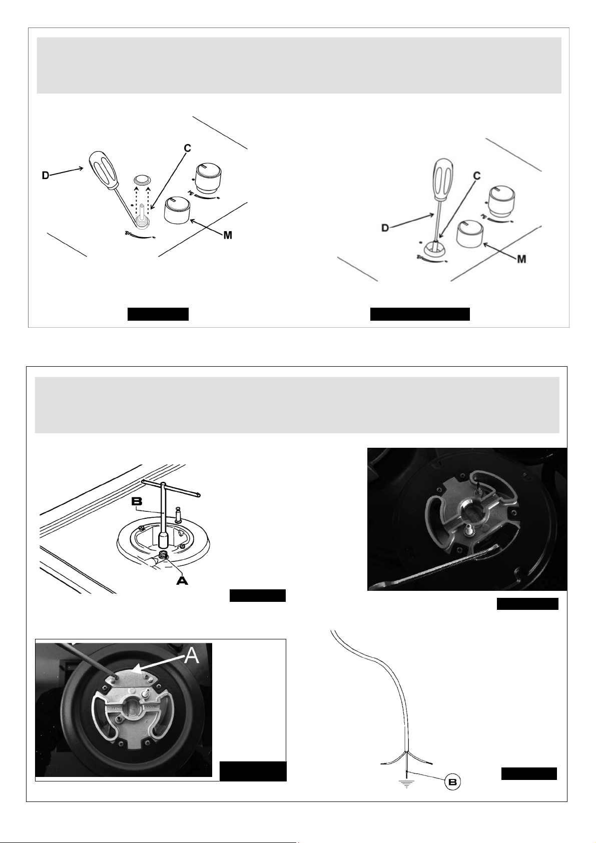
13
ﻝﻛﺷﻟﺍ
14
ﻝﻛﺷﻟﺍ
13
/
ﺃ
ﻝﻛﺷﻟﺍ
13
ﺏﻳﻛﺭﺗﻟﺍ
ﻝﻛﺷﻟﺍ12/ﺃ ﻝﻛﺷﻟﺍ12
ﺕﻼﻳﻭﺣﺗﻟﺍ
ﻝﻛﺷﻟﺍ13/ﺏ
Page 48
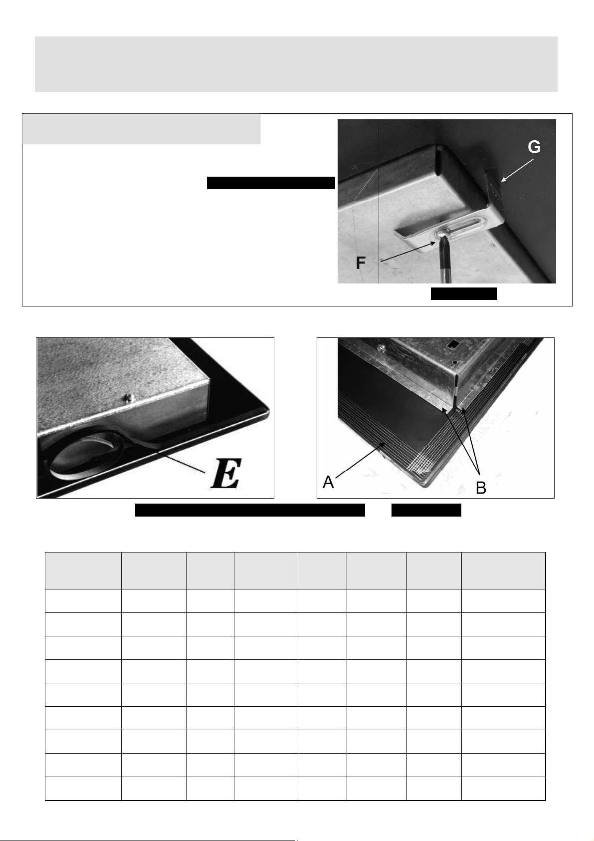
12
11
32300
GZC
(ﺭﺗﻣﻳﻠﻣﻟﺎﺑ) ﺩﺎﻌﺑﻸﻟ ﻝﺛﺗﻣﺍ
ﺏﻳﻛﺭﺗﻟﺍ
ﻉﻭﻧ :ﺏﻳﻛﺭﺗﻟﺍ ﺏ
:ﻝﻳﺩﻭﻣﻟﺍ
ﻝﻛﺷﻟﺍ
11
(ﺯﺎﻬﺟﻟﺍ ﻝﻳﺩﻭﻣ)
ﺏﻳﻛﺭﺗﻟﺍ
ﻉﻭﻧ
A
B
ﺔﺟﺭﺩ
ﺔﻳﻭﺋﻣ
ﻝﻛﺷﻟﺍ
11
/ ﺏ
/ ﺃ
C
ﻝﻛﺷﻟﺍ
D
E
GZC 31330
GZC 32300
GZC 63310
GZC 64300
GZC 64320
GZC 75330
GZC 85320
GZC 95320
GZC 96310
B
B
A
A
A
A
A
A
A
280 490 55 55 160 70 ﻰﻧﺩﺃ ﺩﺣﻛ
280 490 55 55 160 70 ﻰﻧﺩﺃ ﺩﺣﻛ
570 480 60 60 165 70 ﻲﻧﺩﺃ ﺩﺣﻛ
570 480 60 60 165 70 ﻲﻧﺩﺃ ﺩﺣﻛ
570 480 60 60 165 70 ﻲﻧﺩﺃ ﺩﺣﻛ
570 480 60 60 165 70 ﻰﻧﺩﺃ ﺩﺣﻛ
570 480 60 60 165 70 ﻰﻧﺩﺃ ﺩﺣﻛ
850 480 60 60 65 70 ﻲﻧﺩﺃ ﺩﺣﻛ
850 480 60 60 65 70 ﻰﻧﺩﺃ ﺩﺣﻛ
Page 49
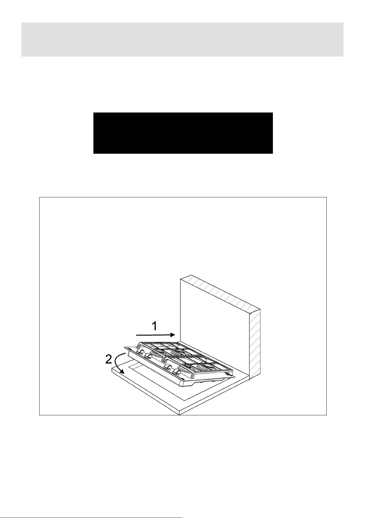
11
ﺏﻳﻛﺭﺗﻟﺍ
ﺩﻗﻭﻣﻠﻟ ﺢﻳﺣﺻﻟﺍ ﺏﻳﻛﺭﺗﻠﻟ ﻊﺑﺗﻣﻟﺍ ءﺍﺭﺟﻹﺍ
Page 50
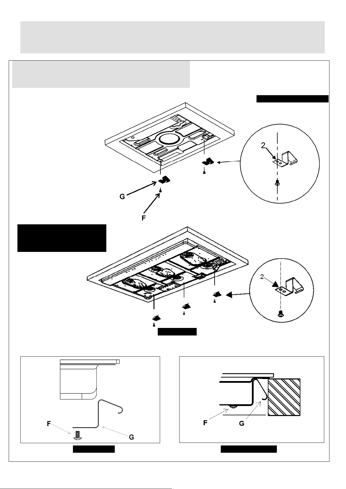
10
ﺏﻳﻛﺭﺗﻟﺍ
ﻲﻔﻠﺧ
ﺃ: ﺩﻭﺳﺃ
ﻉﻭﻧ ﺏﻳﻛﺭﺗﻟﺍ
75330 GZC
ﻝﻳﺩﻭﻣﻟﺍ :
GZC 95320
GZC 96310
:ﻝﻳﺩﻭﻣﻟﺍ
10
ﻝﻛﺷﻟﺍ
10
/ ﺏ
ﻝﻛﺷﻟﺍ
10
/ ﺃ
ﻝﻛﺷﻟﺍ
Page 51
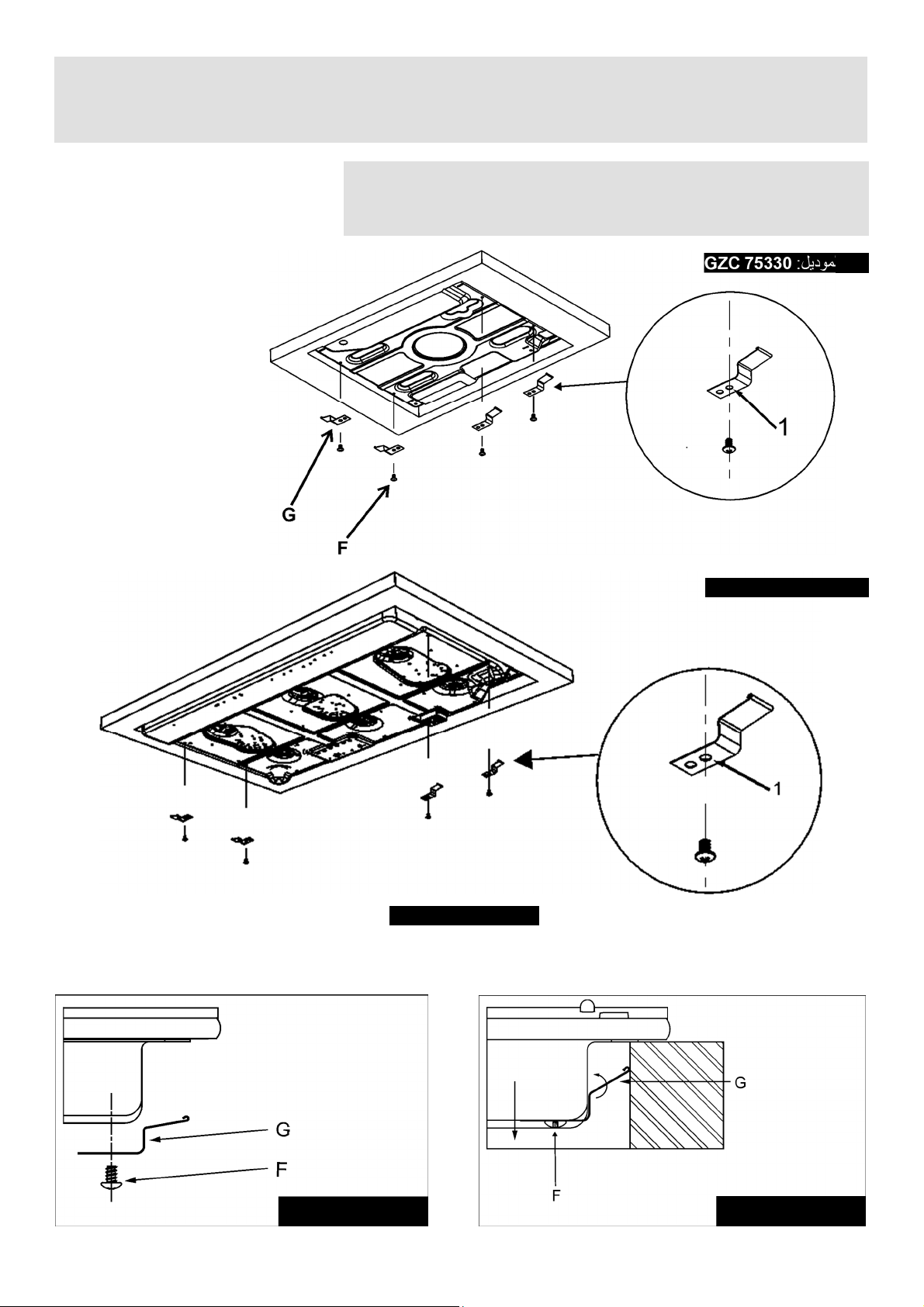
ﺏﻳﻛﺭﺗﻟﺍ
ﻲﺑﻧﺎﺟ ﻡﻭﺭﻛ :ﺃ
ﻉﻭﻧ ﺏﻳﻛﺭﺗﻟﺍ
75330 GZC
ﻝﻳﺩﻭﻣﻟﺍ :
95320 GZC
ﻝﻛﺷﻟﺍ
9
ﻝﻳﺩﻭﻣﻟﺍ :
ﻝﻛﺷﻟﺍ9 /ﺃ ﻝﻛﺷﻟﺍ9/ﺃ
ﻝﻛﺷﻟﺍ9 /ﺏ ﻝﻛﺷﻟﺍ9/ﺏ
Page 52
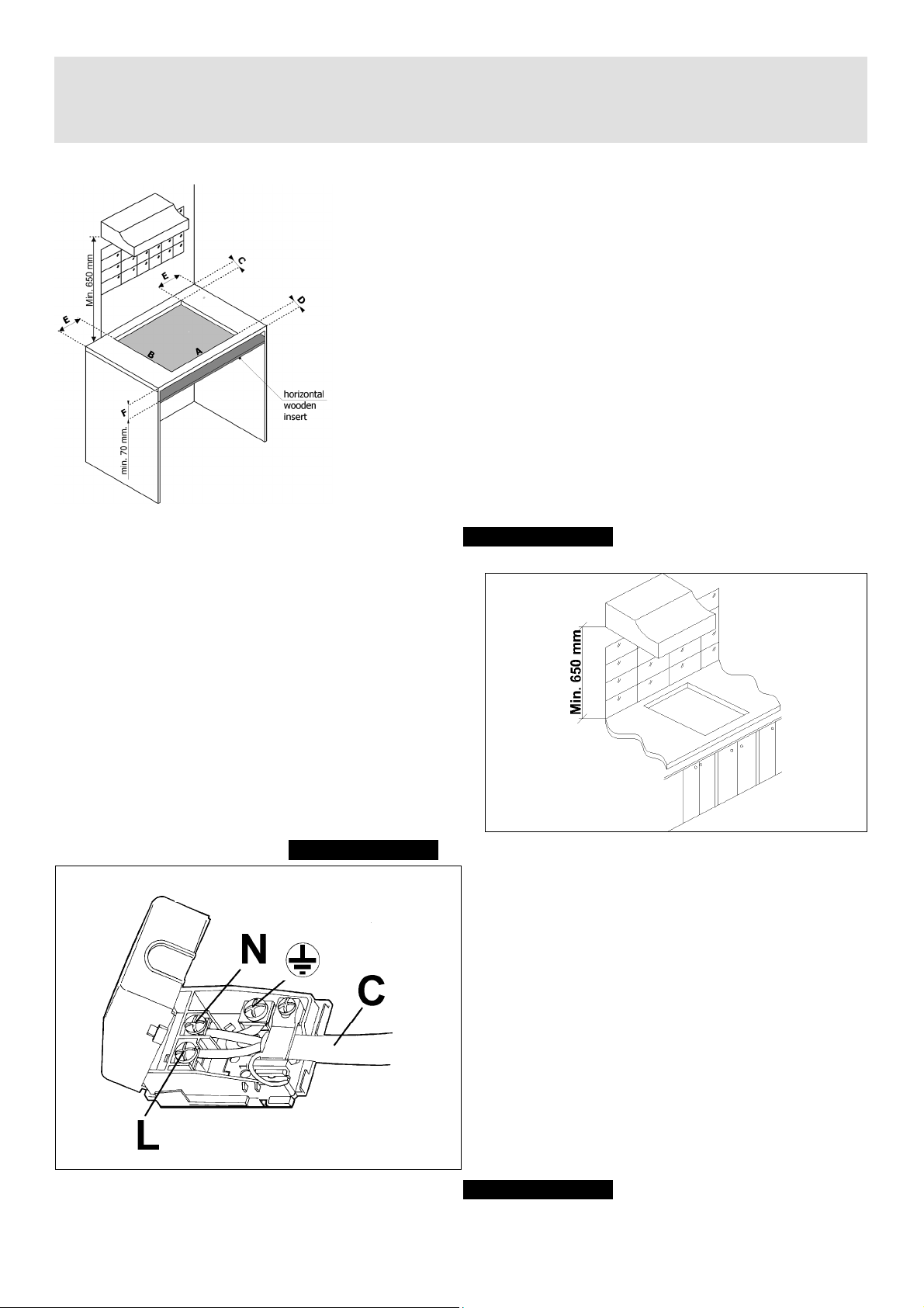
8
ﺏﻳﻛﺭﺗﻟﺍ
ﻝﻛﺷﻟﺍ
7
ﻝﻛﺷﻟﺍ
8
ﻝﻛﺷﻟﺍ
8
/ﺃ
Page 53

7
ﻝﻛﺷﻟﺍ
5
ﻝﻛﺷﻟﺍ
4
ﻝﻛﺷﻟﺍ
3
ﻝﻛﺷﻟﺍ
2
ﻡﺍﺩﺧﺗﺳﻻﺍ
(*)ﻝﺧﺩﻣ ءﺍﻭﻫ :ﺭﻅﻧﺍ ﻝﺻﻓ ﺏﻳﻛﺭﺗﻟﺍ )ﻥﺎﺗﺭﻘﻔﻟﺍ 5 ﻭ6(
ﻑﻳﻅﻧﺗﻟﺍ
ﻝﻛﺷﻟﺍ
ﻝﻛﺷﻟﺍ
ﻝﻛﺷﻟﺍ
6
/ ﺏ
/ ﺃ
6
6
Page 54

6
ﺔﻣﻬﻣ ﺔﻣﻼﺳ ﺕﺍﺭﻳﺫﺣﺗ
●
ﻻ ﻝﻭﺎﺣﺗ ﺭﻳﻳﻐﺗ ﺕﺎﻔﺻﺍﻭﻣﻟﺍ ﺔﻳﻧﻔﻟﺍ ﺞﺗﻧﻣﻠﻟ ﺙﻳﺣ ﻥﻛﻣﻳ ﻥﺃ ﻥﻭﻛﻳ ﻙﻟﺫ
ﺕﺍﺭﻳﺫﺣﺗ ﺔﻣﻬﻣ ﻡﺩﺧﺗﺳﻣﻠﻟ
ءﺎﻧﺛﺃ ،ﻝﻳﻐﺷﺗﻟﺍ ﺢﺑﺻﺗ ﺢﻁﺳﺃ ﻝﻣﻌﻟﺍ ﺔﻘﻁﻧﻣ ﻲﻬﻁﻟﺍ ﺓﺩﻳﺩﺷ ﺔﻧﻭﺧﺳﻟﺍ :ﺩِﻌﺑﺍ
ﻝﺎﻔﻁﻷﺍ ﺎﻬﻧﻋ !
ﺭﻳﺫﺣﺗ
:
ﺊﻔﻁﺍ ﻊﻳﻣﺟ ﺩﻗﺍﻭﻣﻟﺍ ﻱﺃﻭ ﺭﺻﺎﻧﻋ ﻥﻳﺧﺳﺗ ﺔﻳﺋﺎﺑﺭﻬﻛ ﻭ ﻝﺯﻋﺍ ﺯﺎﻬﺟﻟﺍ ﻥﻋ
ﺭﺩﺻﻣ ؛ﺔﻗﺎﻁﻟﺍ
ﻲﻓ ﺔﻟﺎﺣ ﺭﺎﺳﻛﻧﺍ ﺡﻭﻟ ﻥﻳﺧﺳﺗﻟﺍ :
●
● ﻻ ﺱﻣﻠﺗ ﺢﻁﺳ ؛ﺯﺎﻬﺟﻟﺍ
● ﻻ ﻡﺩﺧﺗﺳﺗ ﺯﺎﻬﺟﻟﺍ
●
!ﻡﺎﻫ
ﻥﻭﻛﻳﻟﻭ ﺏﻳﻛﺭﺗﻟﺍ ًﺎﻳﻟﺎﺛﻣ ﺏﺟﻳ ﻁﺑﺿ ﺃ ﻭ ﻝﻳﻭﺣﺗ ﺢﻁﺳ ﺩﻗﻭﻣﻟﺍ ﻻ
ﻡﺍﺩﺧﺗﺳ ﺕﺍﺯﺎﻏ ﻯﺭﺧﺃ ﻭﻫﻭ ﺎﻣ ﺏﻠﻁﺗﻳ ءﻭﺟﻠﻟﺍ ﻰﻟﺇ ﻝﻣﺎﻋ ﺕﺎﺑﻳﻛﺭﺗ
ﻝﻫﺅﻣ : ﻕﺎﻔﺧﻹﺍ ﻲﻓ ﻉﺎﺑﺗﺍ ﻩﺫﻫ ﺓﺩﻋﺎﻘﻟﺍ ﻱﺩﺅﻳ ﻰﻟﺇ ءﺎﻐﻟﺇ ﻥﺎﻣﺿﻟﺍ .
●
ﻡﻬﻣ:ﺏﺟﻳ ﺏﻳﻛﺭﺗ ﺯﺎﻬﺟﻟﺍ ًﺎﻘﻓﻭ ﺕﺎﻣﻳﻠﻌﺗﻟ ﺔﻛﺭﺷﻟﺍ ﺔﻌﻧﺻﻣﻟﺍ .ﻥﻟ ﻝﻣﺣﺗﺗ
ﺔﻛﺭﺷﻟﺍ ﺔﻌﻧﺻُﻣﻟﺍ ﺔﻳﻟﻭﺅﺳﻣﻟﺍ ﻥﻋ ﻱﺃ ﺕﺎﺑﺎﺻﺇ ﺹﺎﺧﺷﻷ ﻭﺃ
ﺕﺎﻧﺍﻭﻳﺣ ﻭﺃ ﻥﺍﺩﻘﻓ ﻲﻓ ﺕﺎﻛﻠﺗﻣﻣﻟﺍ ﻡﺟﺎﻧ ﻥﻋ ﺏﻳﻛﺭﺗﻟﺍ ﺊﻁﺎﺧﻟﺍ .
●
ﺏﻠﻁﺗﻳ ﺏﻳﻛﺭﺗﻟﺍ ﻝﺎﺧﺩﺇ ﺽﻌﺑ ﺕﻼﻳﺩﻌﺗﻟﺍ ﻰﻠﻋ ﻡﺎﻅﻧﻟﺍ ﻲﺋﺎﺑﺭﻬﻛﻟﺍ
ﻲﻟﺯﻧﻣﻟﺍ ﻭﺃ ﻲﻓ ﺔﻟﺎﺣ ﻡﺩﻋ ﻖﻓﺍﻭﺗ ﺱﺑﻘﻣﻟﺍ ﻊﻣ ﺱﺑﺎﻗ ﺯﺎﻬﺟﻟﺍ ﺩﺑﻻ ﻥﻣ
ءﺍﺭﺟﺇ ﺽﻌﺑ ﺕﺍﺭﻳﻳﻐﺗﻟﺍ ﻭﺃ ﺕﻻﺍﺩﺑﺗﺳﻻﺍ ﻰﻠﻋ ﺩﻳ ﺹﺧﺷ ﻝﻫﺅﻣ
ًﺎﻳﻧﻬﻣ ﺏﺟﻳ ﻥﺃ ﺩﻛﺄﺗﻳ ﺍﺫﻫ ﺹﺧﺷﻟﺍ ﻥﻣ ﻥﺃ ﻊﻁﺎﻘﻣ ﻙﻼﺳﺃ ﺱﺑﻘﻣﻟﺍ
ًﺍﺩﻳﺩﺣﺗ ﺏﺳﺎﻧﺗ ﺭﺍﺩﻘﻣ ﺔﻗﺎﻁﻟﺍ ﻲﺗﻟﺍ ﺎﻬﺻﺗﻣﻳ ﺯﺎﻬﺟﻟﺍ .
●ﺞﺗﻧﺗ ﺓﺭﺍﺭﺣﻟﺍ ﺔﺑﻭﻁﺭﻟﺍﻭ ﻥﻋ ﻡﺍﺩﺧﺗﺳﺍ ﺓﺯﻬﺟﺃ ﻲﻬﻁﻟﺍ ﻲﺗﻟﺍ ﻝﻣﻌﺗ ﺯﺎﻐﻟﺎﺑ
ﻲﻓ ﺔﻓﺭﻐﻟﺍ ﺔﺑﻛﺭُﻣﻟﺍ ﺎﻬﺑ .ﺍﺫﻟ ﺏﺟﻳ ﺔﻳﻭﻬﺗ ﺔﻓﺭﻐﻟﺍ ًﺍﺩﻳﺟ ﻅﺎﻔﺣﻟﺎﺑ ﻰﻠﻋ ﺔﻓﺎﻅﻧ
ﺕﺎﺣﺗﻓ ﺔﻳﻭﻬﺗﻟﺍ ﺔﻳﻌﻳﺑﻁﻟﺍ )ﺭﻅﻧﺍ ﻝﻛﺷ 3 ( ﻝﻳﻌﻔﺗﺑﻭ ﺯﺎﻬﺟ ﺔﻳﻭﻬﺗﻟﺍ
ﺔﻳﻛﻳﻧﺎﻛﻳﻣﻟﺍ )ﻁﺎﻔﺷ ﻭﺃ ﺔﺣﻭﺭﻣ ﺔﻳﺋﺎﺑﺭﻬﻛ ﻝﻛﺷ 4 ﻝﻛﺷﻭ 5 .(
● ﺩﻗﺭ ﺏﻠﻁﺗﻳ ﻡﺍﺩﺧﺗﺳﻻﺍ ﻑﻳﺛﻛﻟﺍ ﻝﻳﻭﻁﻟﺍﻭ ﺯﺎﻬﺟﻠﻟ ﺔﻳﻭﻬﺗ ﺔﻳﻓﺎﺿﺇ . ﻥﻛﻣﻳ
ﻖﻳﻘﺣﺗ ﻙﻟﺫ ﻥﻣ ﻝﻼﺧ ﺢﺗﻓ ﺓﺫﻓﺎﻧ ﻭﺃ ﺓﺩﺎﻳﺯﺑ ﺔﻗﺎﻁ ﻡﺎﻅﻧﻟﺍ ﻲﻛﻳﻧﺎﻛﻳﻣﻟﺍ
ﺹﻠﺧﺗﻠﻟ ﻥﻣ ﻡﺩﺎﻌﻟﺍ ﺍﺫﺇ ﻥﺎﻛ ًﺎﺑﻛﺭُﻣ .
)
EMC
؛(
RoHS
(؛
2016/426.
ﻲﺑﻭﺭﻭﻷﺍ ﺩﺎﺣﺗﻻﺍ ﺔﺣﺋﻻ
ًﺍﺭﻁﺧ .
ﺍﺫﺇ ﻥﺎﻛ ﺏﺟﻳ ﻙﻳﻠﻋ ﻑﻗﻭﺗﻟﺍ ﻥﻋ ﻝﺎﻣﻌﺗﺳﺍ ﺯﺎﻬﺟﻟﺍ )ﻭﺃ ﻝﺍﺩﺑﺗﺳﺍ ﻝﻳﺩﻭﻣ ﻡﻳﺩﻗ (،
ﻝﺑﻘﻓ ﺹﻠﺧﺗﻟﺍ ،ﻪﻧﻣ ﻡﻗ ﻪﻠﻳﻁﻌﺗﺑ ﺎﻣﺑ ﻖﻓﺍﻭﺗﻳ ﻊﻣ ﻥﻭﻧﺎﻘﻟﺍ ﻲﻟﺎﺣﻟﺍ ﻲﻧﻌﻣﻟﺍ
ﺔﻳﺎﻣﺣﺑ ﺔﺣﺻﻟﺍ ﺔﻳﺎﻗﻭﻟﺍﻭ ﻥﻣ ﺙﻭﻠﺗﻟﺍ ﻲﺋﻳﺑﻟﺍ ﻝﻌﺟﺑ ﻪﺋﺍﺯﺟﺃ ﺓﺭﻁﺧﻟﺍ ﺭﻳﻏ
،ﺓﺭﺎﺿ ﺔﺻﺎﺧ ﻝﺎﻔﻁﻸﻟ ﻥﻳﺫﻟﺍ ﺩﻗ ﻥﻭﺑﻌﻠﻳ ﺓﺯﻬﺟﻷﺎﺑ ﺔﻠﻣﻬﻣﻟﺍ .
●
:ﺭﻳﺫﺣﺗ
ﻻ ﺱﻣﻠﺗ ﺯﺎﻬﺟﻟﺍ ﻥﻳﺩﻳﺑ ﻭﺃ ﻥﻳﻣﺩﻗ ﻥﻳﺗﺑﻁﺭ ﻭﺃ ﻥﻳﺗﻠﻠﺑﻣ .ﻻ ﻡﺩﺧﺗﺳﺗ ﺯﺎﻬﺟﻟﺍ
ﺕﻧﺃﻭ ﻱﺭﺎﻋ ﻥﻳﻣﺩﻘﻟﺍ
●
ﻥﻟ ﻝﻣﺣﺗﺗ ﺔﻛﺭﺷﻟﺍ ﺔﻌﻧﺻﻣﻟﺍ ﺔﻳﻟﻭﺅﺳﻣﻟﺍ ﻥﻋ ﻱﺃ ﺭﺭﺿ ﺞﺗﺎﻧ ﻥﻋ
ﻡﺍﺩﺧﺗﺳﻻﺍ ﺭﻳﻏ ،ﺏﺳﺎﻧﻣﻟﺍ ﻭﺃ ﺭﻳﻏ ،ﺢﻳﺣﺻﻟﺍ ﻭﺃ ﻁﺭﻔﻣﻟﺍ .
●
- ءﺎﻧﺛﺃ ،ﻝﻳﻐﺷﺗﻟﺍ ﻩﺩﻌﺑﻭ ،ﺓﺭﺷﺎﺑﻣ ﻥﻭﻛﺗ ﺽﻌﺑ ءﺍﺯﺟﺃ ﺩﻗﻭﻣﻟﺍ ﺓﺩﻳﺩﺷ
ﺔﻧﻭﺧﺳﻟﺍ : ﺏﻧﺟﺗﻓ ﺎﻬﺳﻣﻟ.
●
- ﺩﻌﺑ ﻡﺍﺩﺧﺗﺳﺍ ،ﺩﻗﻭﻣﻟﺍ ﺩﻛﺄﺗ ﻥﺃ ﺽﺑﻘﻣﻟﺍ ﻲﻓ ﻊﺿﻭ ،ﻕﻼﻏﻹﺍ ﻖﻠﻏﺍﻭ
ﻡﺎﻣﺻﻟﺍ ﻲﺳﻳﺋﺭﻟﺍ ﺩﺍﺩﻣﻹ ﺯﺎﻐﻟﺍ ﻭﺃ ﺔﻧﺍﻭﻁﺳﺃ ﺯﺎﻐﻟﺍ .
●
- ﻥﺇ ﻡﻟ ﻥﻛﺗ ﺕﺎﻣﺎﻣﺻ ﺯﺎﻐﻟﺍ ﻝﻣﻌﺗ ﻝﻛﺷﺑ ،ﺢﻳﺣﺻ ﻝﺻﺗﺍ ﻡﺳﻘﺑ ﺔﻣﺩﺧ
ءﻼﻣﻌﻟﺍ.
●
ﻅﻔﺗﺣﺍ ﺓﺩﺎﻬﺷﺑ ﻥﺎﻣﺿﻟﺍ ﻭﺃ ﺔﺣﻔﺻ ﺕﺎﻧﺎﻳﺑﻟﺍ ﺔﻳﻧﻘﺗﻟﺍ ﻊﻣ ﺏﻳﺗﻛ ﺕﺎﻣﻳﻠﻌﺗﻟﺍ
ﻝﻼﺧ ﺓﺎﻳﺣ ﺯﺎﻬﺟﻟﺍ . ﺙﻳﺣ ﻱﻭﺗﺣﻳ ﻰﻠﻋ ﺕﺎﻧﺎﻳﺑ ﺔﻳﻧﻘﺗ ﺔﻣﺎﻫ .
ﻡﺎﻫ :
ﻊﻳﻣﺟ ﺎﻧﺗﺎﺟﺗﻧﻣ ﻖﻓﺍﻭﺗﺗ ﻊﻣ ﺭﻳﻳﺎﻌﻣﻟﺍ ﺔﻳﺑﻭﺭﻭﻷﺍ ﺕﻼﻳﺩﻌﺗﻟﺍﻭ ﺔﻳﺑﺳﻧﻟﺍ . ﺍﺫﻟ
ﻖﻓﺍﻭﺗﻳ ﺞﺗﻧﻣﻟﺍ ﻊﻣ ﺕﺎﺑﻠﻁﺗﻣ ﺕﺎﻬﻳﺟﻭﺗﻟﺍ ﺔﻳﺑﻭﺭﻭﻷﺍ ﺔﻳﺭﺎﺳﻟﺍ ﺎﻣﻳﻓ ﻖﻠﻌﺗﻳ ـﺑ :
-
ﻲﺳﻳﻁﺎﻧﻐﻣﻭﺭﻬﻛﻟﺍ ﻖﻓﺍﻭﺗﻟﺍ
-
ﻥﻣﻷﺍ ﻲﺋﺎﺑﺭﻬﻛﻟﺍ) ﺕﺎﻬﻳﺟﻭﺗ ﺩﻬﺟﻟﺍ ﺽﻔﺧﻧﻣﻟﺍ(؛
-
ﺩﻳﻳﻘﺗ ﻡﺍﺩﺧﺗﺳﺍ ﺩﺍﻭﻣ ﺓﺭﻁﺧ ﺔﻧﻳﻌﻣ )
-
ﻡﻳﻣﺻﺗﻟﺍ ﻲﺋﻳﺑﻟﺍ )ﺕﺎﺟﺗﻧﻣ ﺔﻘﻠﻌﺗﻣ ﺔﻗﺎﻁﻟﺎﺑ .(
ﻊﺿﺧﻳ ﺯﺎﻬﺟﻟﺍ ﻡﺎﻛﺣﻷ ﺢﺋﺍﻭﻠﻟﺍ ﺔﻳﻋﺭﻔﻟﺍ ﺕﺎﻬﻳﺟﻭﺗﻟ ﺩﺎﺣﺗﻻﺍ ﻲﺑﻭﺭﻭﻷﺍ :
-
Page 55
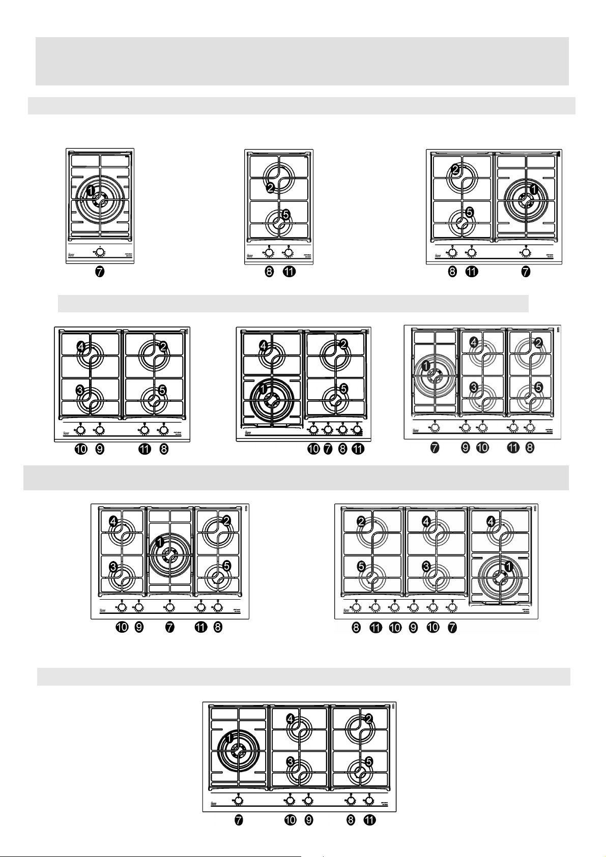
5
ﻑﺻﻭﻟﺍ
03313 GZC
32300 GZC
01363 GZC
64300 GZC
64320 GZC
85320 GZC
GZC 75330
GZC 96310
95320 GZC
Page 56
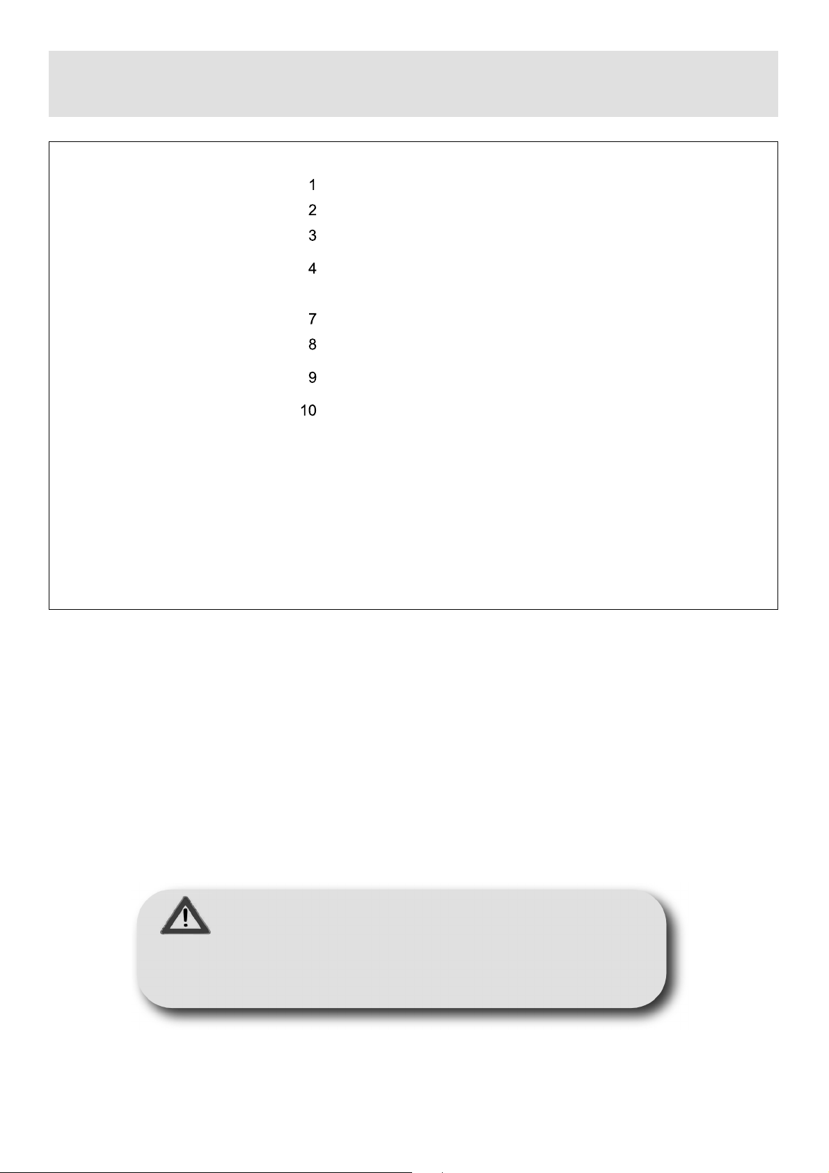
4
ﻪﻳﺑﻧﺗ :ﻡﺗ ﻊﻳﻧﺻﺗ
ﺍﺫﻫ ﺯﺎﻬﺟﻟﺍ
ﻡﺍﺩﺧﺗﺳﻼﻟ
ﻲﻟﺯﻧﻣﻟﺍ
ﻁﻘﻓ ﻡﺗﻳﻟﻭ ﻪﻠﻳﻐﺷﺗ
ﻥﻣ
.ﻱﺩﺎﻋ ﺹﺧﺷ ﻝﺑﻗ
*
DCC AFB
:
ءﺍﻭﻬﻟﺍ
ﺙﻌﺑﻧﻳﻥﻣ
ﻝﻔﺳﻷﺍ
ﻝﻛﺷﻟﺍ )13\ﺏ.(
4000
ﺕﺍﻭ
ﺩﻗﻭﻣ ﺯﺎﻏ ﻖﺋﺎﻓ ﺔﻋﺭﺳﻟﺍ
*)DCC
AFB
(
5
11
ﻑﺻﻭﻟﺍ
2800
ﺩﻗﻭﻣﺯﺎﻏ ﻊﻳﺭﺳ
ﺩﻗﻭﻣ ﺯﺎﻏ ﻪﺑﺷ ﻊﻳﺭﺳ ﻝﺯﺗﺧﻣ ﺏﻬﻠﻟﺍ
ﺩﻗﻭﻣ ﺯﺎﻏ ﻪﺑﺷ ﻊﻳﺭﺳ
ﺯﺎﻏ ﺩﻗﻭﻣ ﻲﻓﺎﺿﺇ
ﺕﺍﻭ
ﺕﺍﻭ
ﺕﺍﻭ
ﺕﺍﻭ
1400
1750
1000
ﺽﺑﻘﻣ ﻡﻛﺣﺗﻟﺍ ﻲﻓ ﻥﻳﻋ ﻥﻳﺧﺳﺗﻟﺍ ﻡﻗﺭ 1
ﺽﺑﻘﻣ ﻡﻛﺣﺗﻟﺍ ﻲﻓ ﻥﻳﻋ ﻥﻳﺧﺳﺗﻟﺍ ﻡﻗﺭ 2
ﺽﺑﻘﻣ ﻡﻛﺣﺗﻟﺍ ﻲﻓ ﻥﻳﻋ ﻥﻳﺧﺳﺗﻟﺍ ﻡﻗﺭ 3
ﺽﺑﻘﻣ ﻡﻛﺣﺗﻟﺍ ﻲﻓ ﻥﻳﻋ ﻥﻳﺧﺳﺗﻟﺍ ﻡﻗﺭ 4
ﺽﺑﻘﻣ ﻡﻛﺣﺗﻟﺍ ﻲﻓ ﻥﻳﻋ ﻥﻳﺧﺳﺗﻟﺍ ﻡﻗﺭ 5
ﻡﻣﺻ ﺢﻁﺳ ﺩﻗﻭﻣﻟﺍ ﻡﺩﺧﺗﺳﻳﻟ ًﺎﻳﺭﺻﺣ ﺯﺎﻬﺟﻛ ﻲﻬﻁﻠﻟ :ﻱﺃﻭ ﻡﺍﺩﺧﺗﺳﺍ ﺭﺧﺁ ﻪﻟ ﺩﻌﻳ ﺭﻳﻏ ﻡﺋﻼﻣ ﻝﺛﻣُﻳﻭ
ﺓﺭﻭﻁﺧ
Page 57

3
:ﺱﺭﻬﻔﻟﺍ
4
ﺔﺣﻔﺻ
ﺔﺣﻔﺻ
ﺔﺣﻔﺻ
ﺔﺣﻔﺻ
ﺔﺣﻔﺻ
ﺔﺣﻔﺻ
ﺔﺣﻔﺻ
ﺔﺣﻔﺻ
14
15
16
17
18
19
6
ﺔﻣﻬﻣ ﺔﻣﻼﺳ ﺕﺍﺭﻳﺫﺣﺗ
ﻑﺻﻭﻟﺍ
ﺕﺎﻧﺎﻳﺑﻟﺍ ﺔﻳﻧﻘﺗﻟﺍ ﻁﺑﺿﻟ ﻖﻓﺩﺗ ﺯﺎﻏ ﺯﺎﻬﺟﻟﺍ
ﺕﺎﻧﺎﻳﺑﻟﺍ ﺔﻳﻧﻘﺗﻟﺍ ﻰﻠﻋ ﻖﺻﻠﻣ ﺕﺎﻧﺎﻳﺑﻟﺍ
ﻡﺍﺩﺧﺗﺳﻻﺍ ﺔﻳﻔﻳﻛ
ﻑﻳﻅﻧﺗﻟﺍ - ﺏﻳﻛﺭﺗﻟﺍ
ﺕﻳﺑﺛﺗﻟﺍ
ﺏﻳﻛﺭﺗﻟﺍ- ﺯﺎﻐﻟﺍ ﻝﻳﺻﻭﺗ
ﺔﺣﻔﺻ
ﺔﺣﻔﺻ
ﺔﺣﻔﺻ
ﺔﺣﻔﺻ
20
21
22
23
ﺏﻳﻛﺭﺗﻟﺍ
ﺕﻼﺻﻭﻟﺍ
ﺔﻳﺋﺎﺑﺭﻬﻛﻟﺍ
ﺕﺎﻣﺎﻣﺻ ﻁﺑﺿﻟﺍ
ﺃ
-
ﺭﺎﻳﻐﻟﺍ ﻊﻁﻗﻭ ﻲﻧﻘﺗﻟﺍ ﻡﻋﺩﻟﺍ
-
ﺕﻼﻳﻭﺣﺗﻟﺍ
ﺔﻧﺎﻳﺻﻟﺍ
:ﺭﻳﺫﺣﺗ
ﺏﺟﻳ ﺩﺎﻌﺑﺇ ﻝﺎﻔﻁﻷﺍ ﻥﻳﺫﻟﺍ ﻝﻘﺗ ﻡﻫﺭﺎﻣﻋﺃ ﻥﻋ 8 ﻡﺍﻭﻋﺃ ﻥﻋ ﺯﺎﻬﺟﻟﺍ ﺍﺩﻋ ﻲﻓ ﺔﻟﺎﺣ ﻑﺍﺭﺷﻹﺍ ﺭﻣﺗﺳﻣﻟﺍ .
ﻥﻛﻣﻳ ﻡﺍﺩﺧﺗﺳﺍ ﺯﺎﻬﺟﻟﺍ ﻥﻣ ﻝﺑﻗ ﻝﺎﻔﻁﻷﺍ ﻥﻳﺫﻟﺍ ﺍﻭﺯﻭﺎﺟﺗ ﺔﻧﻣﺎﺛﻟﺍ ﻥﻣ ﺭﻣﻌﻟﺍ ﺹﺎﺧﺷﻷﺍﻭ ﻥﻳﺫﻟﺍ ﻥﻭﻧﺎﻌﻳ ﻥﻣ ﺽﺎﻔﺧﻧﺍ ﺓﺭﺩﻘﻟﺍ ﺔﻳﺩﺳﺟﻟﺍ ﻭﺃ ﺔﻳﺳﺣﻟﺍ ﻭﺃ
ﺔﻳﻠﻘﻌﻟﺍ ﻭﺃ ﻥﻣ ﻥﻭﺭﻘﺗﻔﻳ ﻰﻟﺇ ﺓﺭﺑﺧﻟﺍ ﺔﻓﺭﻌﻣﻟﺍﻭ ﺍﺫﺇ ﻥﺎﻛ ﻙﻟﺫ ﺕﺣﺗ ﻑﺍﺭﺷﻹﺍ ﻭﺃ ﺩﻌﺑ ﻡﻫﺩﻳﻭﺯﺗ ﺕﺍﺩﺎﺷﺭﺈﺑ ﻝﻭﺣ ﻡﺍﺩﺧﺗ ﺳﺍ ﺯﺎﻬﺟﻟﺍ ﺔﻘﻳﺭﻁﺑ ﺔﻧﻣﺁ
ﻡﻬﻓﻭ ﺭﻁﺎﺧﻣﻟﺍ ﻲﺗﻟﺍ ﻱﻭﻁﻧﻳ ﺎﻬﻳﻠﻋ.
ﺏﺟﻳ ﻡﺩﻋ ﺡﺎﻣﺳﻟﺍ ﻝﺎﻔﻁﻸﻟ ﺏﻌﻠﻟﺎﺑ ﺯﺎﻬﺟﻟﺎﺑ .
ﻻ ﺏﺟﻳ ﻥﺃ ﻡﻭﻘﻳ ﻝﺎﻔﻁﻷﺍ ﻑﻳﻅﻧﺗﻟﺎﺑ ﺔﻧﺎﻳﺻﻭ ﻡﺩﺧﺗﺳﻣﻟﺍ ﻥﻭﺩﺑ ﻑﺍﺭﺷﺇ .
Page 58

2
ﺕﻼﻳﺩﻭﻣﻟﺍ :GZC 32300
GZC 31330
GZC 63310
GZC 64320
GZC 85320
GZC 64300
GZC 75330
GZC 95320
GZC 96310
PCZT
Cod: 04167HG - 01.09.2020 - Rev. 01
:ﻉﻭﻧﻟﺍ
Page 59

Page 60
AR
ﻝﻳﻟﺩ ﻡﺩﺧﺗﺳﻣﻟﺍ
www.teka.com
GZC
Cod: 04167HG - 22.10.2020 - Rev. 01
ﺔﻋﻭﻣﺟﻣ
 Loading...