

Teka E/60.2 4G AI AL, E/60.2 3G 1P AI, E/60.2 3G AI AL, E/60.2 4P, ES/60.2 4G Installation Manual And Recommendations For Use And Maintenance
...Page 1

Installation manual and recommendations for
use and maintenance. Hobs
E/60.2 4G – E/60.2 4G AI – E/60.2 4G AI AL – E/60.2 3G 1P –
E/60.2 3G 1P AI – E/60.2 3G AI AL – E/60.2 4P - ES/60.2 4G –
ES/60.2 4G AL – ES/60.2 4G AI – ES/60.2 4G AI AL –
ES/60.2 3G 1P – ES/60.2 3G 1P AI – ES/60.2 3G AI AL –
ES/60.2 4G AI AL RÚSTICA
Hinweise für den einbau und empfehlungen für den
betrieb und die wartung. Von kochplatten
E/60.2 4G – E/60.2 4G AI – E/60.2 4G AI AL – E/60.2 3G 1P –
E/60.2 3G 1P AI – E/60.2 3G AI AL – E/60.2 4P - ES/60.2 4G –
ES/60.2 4G AL – ES/60.2 4G AI – ES/60.2 4G AI AL –
ES/60.2 3G 1P – ES/60.2 3G 1P AI – ES/60.2 3G AI AL –
ES/60.2 4G AI AL RÚSTICA
Instructions pour l’installation et recommandations
pour l’utilisation et l’entretien plaques de cuisson
E/60.2 4G – E/60.2 4G AI – E/60.2 4G AI AL – E/60.2 3G 1P –
E/60.2 3G 1P AI – E/60.2 3G AI AL – E/60.2 4P - ES/60.2 4G –
ES/60.2 4G AL – ES/60.2 4G AI – ES/60.2 4G AI AL –
ES/60.2 3G 1P – ES/60.2 3G 1P AI – ES/60.2 3G AI AL –
ES/60.2 4G AI AL RÚSTICA
Page 2

Dear Customer,
Thank you for choosing a TEKA hob.
We are sure that our product will fully satisfy
your requirements.
This modern, functional and practical applian-
ce has been built using top quality materials
which are subjected to strict quality contro l s
throughout the manufacturing process.
B e f o re installing or using our product, we
recommend you to carefully read this manual
and follow its instructions step by step in
order to obtain the best possible results.
Keep this instruction manual in a safe place
so that you can consult it whenever necessary
and comply with the warranty requirements.
To benefit from our warranty you must present
the invoice for the purchase together with the
warranty certificate.
Safety Instructions
B e f o re using your hob for the first time,
please read the installation and connection
instructions carefully.
These hobs can be installed in the same
kitchen units as TEKA ovens.
We recommend that our hobs are installed
by authorised technical personnel according
to the applicable installation regulations.
Any internal handling of the hob or gas
t r a n s f o rmation to a gas other than that
s t a n d a rdised by the manufacturers must be
c a rried out only by TEKA Technical Service
personnel.
WARNING
To avoid the risk of burns, keep children away
from the hob during or after its operation.
User’s Guide to this Instruction Manual
2
Page 3
Introduction Page 4
Description of the hobs 4
Installation 7
Positioning of the hobs 7
Positioning of the oven 8
Anchoring of the hob 8
Gas connection 8
Electrical connection 9
Gas transformation 9
Technical Information 11
Dimensions and power 11
Technical Data 12
Rating Plates 14
Use and maintenance 16
Special requirements before first use 16
Lighting of burners 16
Safety system components 17
Suggestions for the proper use of burners 17
Cleaning and conservation of burners 18
Maintenance of the burners 19
Operation of hobs with electric hotplates 19
Suggestions for the proper use
of electric hotplates 20
Cleaning and conservation of electric
hotplates 20
If something doesn´t work 23
Contents
3
Page 4
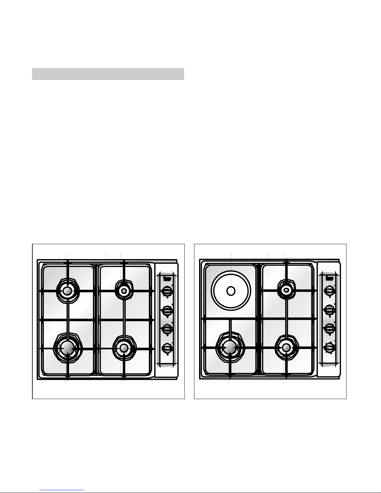
E/60.2 4G, E/60.2 4G AI y E/60.2 4G AI AL
Models (see drawing 1)
1 Small burner of 860 Kcal/h - 1 kW.
2 I n t e rmediate burner of 1.500 Kcal/h -
1,75 kW.
3 I n t e rmediate burner of 1.500 Kcal/h -
1,75 kW.
4 Large burner of 2.580 Kcal/h - 3 kW.
5 Pan support.
• Maximum calorific power: 6.450 Kcal/h 7,5 kW.
• P redicted operation pre s s u res: as indicated
in the rating plate affixed to the hob case.
E/60.2 3G 1P, E/60.2 3G 1P AI and E/60.2
3G 1P AI AL Models (see drawing 2)
1 Small burner of 860 Kcal/h - 1 kW.
2 I n t e rmediate burner of 1.500 Kcal/h -
1,75 kW.
3 Electric hotplate 1.500 W., Ø 145 mm.
4 Large burner 2.580 Kcal/h - 3 kW.
5 Pan support.
• Maximum calorific power: 4.950 Kcal/h 5,75 kW.
• Maximum electric power: 1,5 kW.
• Operation pre s s u res: as indicated in the
rating plate affixed to the hob case.
Introduction
4
Description of the Appliance
3 15
24
53 1
24
Drawing 1 Drawing 2
Page 5

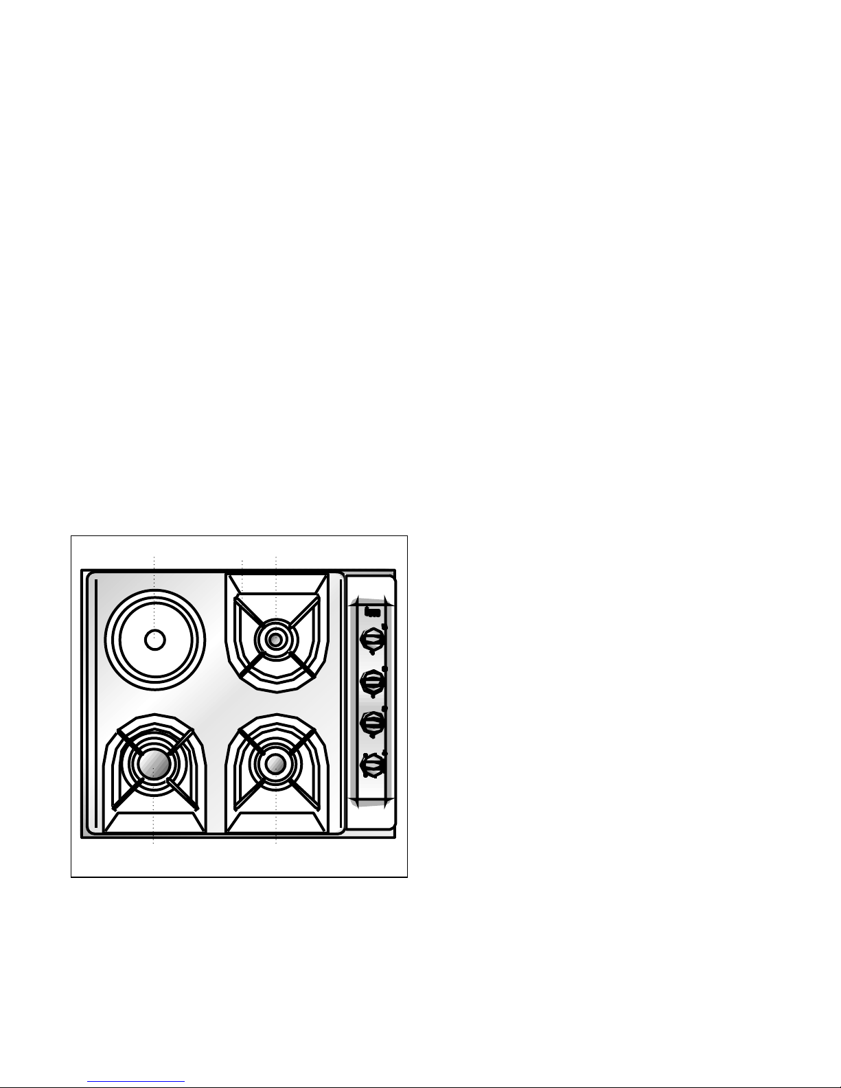
E/60.2 4P. Model (see drawing 3)
1 Electric hotplate of 1.000 W., Ø 145 mm.
2 Electric hotplate of 1.500 W., Ø 180 mm.
3 Electric hotplate of 1.500 W., Ø 145 mm.
4 Electric hotplate of 1.500 W., Ø 180 mm.
• Maximum electric power: 5,5 kW.
ES/60.2 4G, ES/60.2 4G AI, ES/60.2 4G AI
AL , ES/60.2 4G AL and ES/60.2 4G AI AL
RÚSTICA Models (see drawing 4)
1 Small burner of 860 Kcal/h - 1 kW.
2 I n t e rmediate burner of 1.500 Kcal/h -
1,75 kW.
3 I n t e rmediate burner of 1.500 Kcal/h -
1,75 kW.
4 Large burner of 2.580 Kcal/h - 3 kW.
5 Pan support.
• Maximum calorific power: 6.450 Kcal/h -
7,5 kW.
• P redicted operation pre s s u res: as indicated
in the rating plate affixed to the hob case.
5
2 1
43
2 15
34
Drawing 3 Drawing 4
Page 6
6
ES/60.2 3G 1P, ES/60.2 3G 1P AI and
ES/60.2 3G 1P AI AL Models (see drawing 5)
1 Small burner of 860 Kcal/h - 1 kW.
2 I n t e rmediate burner of 1.500 Kcal/h -
1,75 kW.
3 Electric heating element of 1.500 W., Ø
145 mm.
4 Large burner of 2.580 Kcal/h - 3 kW.
5 Pan support.
• Maximum calorific power: 4.950 Kcal/h 5,75 kW.
• Electric power: 1,5 kW.
• P redicted operation pre s s u res: as indicated in the rating plate affixed to the hob
case.
3 15
24
Drawing 5
Page 7

I N S TA L L ATION AND ADJUSTMENT MUST BE
CARRIED OUT BY AUTHORISED TECHNICAL
PERSONNEL ACCORDING TO THE APPLICABLE
INSTALLATION REGULATIONS.
An opening must be made in the worktop of
the dimensions specified in drawing 6.
The hob may be attached to kitchen units 20,
30 and 40 mm thick.
When positioning the hob there must be a
ventilation slot of 110 cm2at the front of the
kitchen unit. The minimum distance from the
lower part of the hob to the kitchen unit must
be 20 mm If there is not a ventilation slot, the
minimum distance from the hob to the kitchen
unit must be 130 mm
These hobs only function with TEKA ovens.
The minimum vertical distance of the lower
part of the piece of furniture placed above the
hob will be 600 mm.
The piece of furn i t u re where the hob with oven
is to be placed will be properly fixed.
Installation
7
Important
Positioning of
the hobs
B
D
C
E
Drawing 7
Ventilation slot
Worktop
In order to install these hobs in kitchen
units of 60 cm, the opening in the worktop
must coincide exactly with the interior of
the kitchen unit on the side of the controls of the hob.
Kitchen unit of 60 cm
Detail.
C
B
Drawing 8
A
B
C
D
E
20
A
fig. 6
Page 8

See the applicable manual.
Once the hob position has been dimensioned,
the seal must be affixed (J) to the hob.
Fix the clamps (K) into the holes on the lower
p a rt of the case, as shown in drawing 9, by
tightening the four screws supplied (ø4.2
mm).
The clamps (K) and seal (J) are supplied in the
packaging along with the hob.
The gas connection of the hob must be made
in accordance with the applicable installation
standards or regulations.
The room must be provided with adequate
ventilation, in accordance with the applicable
regulations.
The hob is pre p a red with a 1/2” diameter
s c rew connection according to ISO 228-1. A
ø10/12 mm copper pipe to which the gas
supply pipe can be welded is supplied as an
accessory.
Each time the gas connection nut is re m o v e d
the washer must be replaced.
To avoid causing damage to the hob during
installation when tightening the gas pipe
connection nut, a maximum grip torque of 350
cm kgf must be used.
Once the gas connection has been made,
the airtightness of the installation must be
checked. If the check is made using air, the
testing pressure must be no greater than 200
g/cm2. If air is not available, use soapy water
to check that no leak is produced at the
connections. It is strictly recommended not to
use a flame to make the check.
Once the hob has been installed, check that
the flame is regulated at its minimum setting.
To make this check light the burners and make
s u re that they do not go out when you change
rapidly from high to low.
Do not connect the hobs with urban gas
containing CO.
8
Positioning of the oven
Anchoring of the hob
Gas connection
K
K
K
fig. 9
Page 9

9
B e f o re connecting the hob to the power
s u p p l y, check that the voltage and fre q u e n c y
a re those specified in the rating plate located
on the lower part of the hob.
The power supply connection must be done by
using an easily accessible omni-pole switch or
plug suitable for the strength to be support e d
and with a minimum distance of 3 mm
between contacts to guarantee the switchingo ff in emergency situations or when cleaning
the hob.
Connection must be done by using an
a p p ropriate earth connection according to the
applicable regulations.
In the event that it were necessary to change
the flexible power supply cable in these hobs,
it must be replaced by official TEKA technicians
as special tools are required.
P revent any contact of the power supply cable
either with the case of the hob or with that of
the oven, if this is installed in the same unit.
Ventilation:
• Take into account that certain oven models
require the installation of a top ventilation slot
of a size between 30 and 40 mm (consult the
applicable manual).
Warning:
• If the furn i t u re under the hob is going to be
used for the storage of products, the minimum
distance between these products and the hob
must be 15 cm. It should be also taken into
account that temperature inside the furn i t u re
may reach 600C.
• The glues used in the manufacturing of the
f u rn i t u re or when gluing the decorative
tissues, as well as those which are part of
the worktops, must be pre p a red to bear
temperatures of up to 1000C.
Important!
The transformation of the appliance to use a
d i ff e rent gas to that for which it has been
sold must only be carried out by a qualified
technician.
I n f o rmation for the Technical Ser v i c e : in the
event of conversion of the type of gas or
p re s s u re in the appliance, the new re g u l a t i o n
label must be placed over the existing one, in
o rder to identify the new characteristics after
the changeover.
To make the transformation replace the gas
nozzles and regulate the minimum settings of
the taps.
The gas nozzles necessary for each type of
gas are indicated in table 1.
Electrical connection
Gas transformation
Page 10

To replace the gas nozzles it is necessary to
follow the following instructions:
• Remove the pan supports and the top part
of the burners in order to access the nozzle.
• Use a no 7 tubular spanner to remove
the nozzles and replace them with the
c o rresponding alternative nozzles. Take care
to tighten the nozzles well so as to avoid the
risk of gas leaks.
• Reposition the pan support and burn e r
covers.
Once the gas nozzles have been replaced, the
following instructions must be followed to
graduate the minimum settings .
• Remove the controls and joints from the
control panel to access the gas taps.
• Light the burners at their minimum setting.
• Use a small screw-driver to remove the
s c rew on the right or centre of the plug of the
gas key until the minimum flame is set (turn
left to increase the flame and right to decre ase the flame).
• Once the setting has been graduated check
that the flame remains at its minimum setting
when the control is brusquely turned between
the maximum and minimum setting
TEKA INDUSTRIAL, S.A. will not accept
responsibility for incorrect hob operation if the
gas transformation and regulation of minimum
b u rner settings are not carried out by TEKA’s
official Technical Service.
10
Table 1
Burner Family
First Second Third
Group a Group c Group e Group H Group E+ Group 3+
Large 260 260 260 116 116 85
Inmediate 185 185 185 97 97 65
Small 145 145 145 72 72 50
Gas nozzle diameter ø expressed in 1/100 mm.
Page 11

Technical information
11
Dimensions and powers
M o d e l s
E/60.2 4G. E/60.2 4G. AI E/60.2 3G.1P E/60.2 4G
ES/60.2 4G AI
ES/60.2 3G. 1P
E/60.2 4G. AI AL
E/60.2 3G 1P A
I
E/60.2 4P ES/60.2 4G AL ES/60.2 4G AI AL
ES/60.2 3G. 1P AI
E/60.2 3G 1P AI AL RÚSTIC
ES/60.2 3G 1P AI AL
Dimensions of the hob
Height (mm) 109 109 109 103 107 107 107
Length (mm) 600 600 600 600 600 600 600
Width (mm) 510 510 510 510 435 510 510
Dimensions of position on the worktop
Length (mm) 582 582 582 582 582 582 582
Width (mm) 492 492 492 492 492 492 492
Power by burner and electric hotplate
Gas
burner 3 Kw.
1 1 1 1 1 1
Intermediate
gas burner 1,75 Kw.
2 2 1 2 2 1
Small gas
burner 1 Kw.
1 1 1 1 1 1
Electric hotplate
Ø 145 mm.,
1.000 W
1
Electric hotplate
Ø 145 mm.,
1.500 W
1 1 1
Electric hotplate
ø 180 mm.,
1.500W
2
Electrical features:
Maximum nominal
power (W)
0’6 1.500 5.500 0,6 1.500
Supply
voltage (V)
220 / 240 230 230 220/240 230
Frequency (Hz)
50 / 60 50 / 60 50 / 60 50 / 60 50 / 60
Gas:
Maximum power Kw. 7’5 7’5 5’75 7,5 7’5 5,75
Page 12

COMMON CHARACTERISTICS TO THE ELECTRIC HOTPLATES AND AUTOMATIC LIGHTING
MODEL
The supply voltage and frequency must be
those indicated in the rating plate. The fire
p rotection is of “X” type. The hob must be
installed at over 15 cm away from the side walls.
(See drawing 10).
In the event of a hotplate being cracked the
hob must be switched off at the mains.
COMMON CHARACTERISTICS TO EVERY
MODEL WITH GAS BURNERS
Warnings:
a) “Before installing, make sure that the local
distribution conditions (gas type and pressure)
a re compatible with the setting of the appliance”.
b) “ The setting conditions, of this appliance
are printed on the label (or the rating plate)”.
c) “This appliance must not be connected to a
device for the evacuation of combustion products. Its installation and connection will be
c a rried out according the installation rules in force. Special attention will be paid to the applicable specifications concerning ventilation”.
Attention: The use of a gas cooking appliance, produces heat and humidity in the ro o m
w h e re it is installed. Good ventilation of the
kitchen must be ensured by keeping the natural ventilation holes open or by opening a window or installing an efficient mechanical ventilation device (mechanical ventilation hood).
12
Technical Data
Drawing 10
Table 2
Country Category
Spain III1ace2H3+
Portugal II2H3+
France II2E+3+
United Kingdom II2H3+
Greece I3+
Page 13

COMMON CHARACTERISTICS TO EVERY
MODEL
N.B.: All the hob models r e f e rred to in this
manual have hot zones during or after their
use and can cause burns.
Care must be taken when handling these hobs
b e f o re installation as there may be ro u g h
zones or corners which may be dangerous.
Table 3
13
Burner Large Intermediate Small
Nominal Calorific Consumption KW 3 1,75 1
Nominal Consumption* G-130 (Nm3/h) 0,42 0,24 0,14
G-150 (Nm3/h) 0,54 0,31 0,18
G-110 (Nm3/h) 0,68 0,40 0,23
G-20 (Nm3/h) 0,29 0,17 0,10
G-25 (Nm3/h) 0,33 0,19 0,11
G-30 (Kg/h) 0,22 0,13 0,07
G-31 (Kg/h) 0,21 0,13 0,07
Low Calorific Consumption kW 0,77 0,47 0,33
Result % >52 >52 –
* Consumption on High Calorific Power (H.C.P.)
Page 14

14
T E K A INDUSTRIAL, S.A.
SANTANDER - ESPAÑA
Mod.
E/60.2 4G
G-110 Vr Nm
3
/h G-20 Vr
Nm3/h1.70 0.71
G-130 Vr Nm
3
/h G-25 Vr
Nm3/h1.05 0.83
G-150 Vr
ES FR
Nm
3
/h G-30 Mr
Kg/h1.35 0.55
G-31 Mr
Kg/h0.54
∑ Qn
(P.C.S.)
7.50
Clase
3
Nº
Cat. Kat I I I 1 a c e 2 H 3 + I I 2 E + 3 +
p (mbar) 8 - 1 8 - 2 8 / 3 7 20/25 28/37
GB GR PT
Cat. Kat I I 2 H 3 + I 3 + I I 2 H 3 +
p (mbar) 2 0 - 2 8 / 3 7 2 8 / 3 7 2 0 - 3 0 / 3 7
ELECT. H∆EKTPIKO
TYP. A12312000
T E K A INDUSTRIAL, S.A.
SANTANDER - ESPAÑA
Mod.
E/60.2 3G.1P
G-110 Vr Nm
3
/h G-20 Vr
Nm3/h1.30 0.55
G-130 Vr Nm
3
/h G-25 Vr
Nm3/h0.80 0.64
G-150 Vr
ES FR
Nm
3
/h G-30 Mr
Kg/h1.03 0.42
G-31 Mr
Kg/h0.41
∑ Qn
(P.C.S.)
5.75
Clase
3
Nº
Cat. Kat I I I 1 a c e 2 H 3 + I I 2 E + 3 +
p (mbar) 8 - 1 8 - 2 8 / 3 7 20/25 28/37
GB GR PT
Cat. Kat I I 2 H 3 + I 3 + I I 2 H 3 +
p (mbar) 2 0 - 2 8 / 3 7 2 8 / 3 7 2 0 - 3 0 / 3 7
ELECT. H∆EKTPIKO
TYP. A1D312000
230V~
50/60 HZ. 1.500W
T E K A INDUSTRIAL, S.A.
SANTANDER - ESPAÑA
Mod.
E/60.2 4G AI AL
E/60.2 4G AI
G-110 Vr Nm
3
/h G-20 Vr
Nm3/h1.70 0.71
G-130 Vr Nm
3
/h G-25 Vr
Nm3/h1.05 0.83
G-150 Vr
ES FR
Nm
3
/h G-30 Mr
Kg/h1.35 0.55
G-31 Mr
Kg/h0.54
∑ Qn
(P.C.S.)
7.50
Clase
3
Nº
Cat. Kat I I I 1 a c e 2 H 3 + I I 2 E + 3 +
p (mbar) 8 - 1 8 - 2 8 / 3 7 20/25 28/37
GB GR PT
Cat. Kat I I 2 H 3 + I 3 + I I 2 H 3 +
p (mbar) 2 0 - 2 8 / 3 7 2 8 / 3 7 2 0 - 3 0 / 3 7
ELECT. H∆EKTPIKO
TYP. A1231200E
230 V~
50/60 HZ. 0’6W
0 0 9 9
0 0 9 9
0 0 9 9
Page 15

15
T E K A INDUSTRIAL, S.A.
SANTANDER - ESPAÑA
Mod.
E/60.2 3G.1PAI AL
E/60.2 3G.1PAI
G-110 Vr Nm
3
/h G-20 Vr
Nm3/h1.30 0.55
G-130 Vr Nm
3
/h G-25 Vr
Nm3/h0.80 0.64
G-150 Vr
ES FR
Nm
3
/h G-30 Mr
Kg/h1.03 0.42
G-31 Mr
Kg/h0.41
∑ Qn
(P.C.S.)
5.75
Clase
3
Nº
Cat. Kat I I I 1 a c e 2 H 3 + I I 2 E + 3 +
p (mbar) 8 - 1 8 - 2 8 / 3 7 20/25 28/37
GB GR PT
Cat. Kat I I 2 H 3 + I 3 + I I 2 H 3 +
p (mbar) 2 0 - 2 8 / 3 7 2 8 / 3 7 2 0 - 3 0 / 3 7
ELECT. H∆EKTPIKO
TYP. A1D31200E
230V~
50/60 HZ. 1.500W
T E K A INDUSTRIAL, S.A.
SANTANDER - ESPAÑA
Mod.
ES/60.2. 4G. AL
G-110 Vr Nm
3
/h G-20 Vr
Nm3/h1.70 0.71
G-130 Vr Nm
3
/h G-25 Vr
Nm3/h1.05 0.83
G-150 Vr
ES FR
Nm
3
/h G-30 Mr
Kg/h1.35 0.55
G-31 Mr
Kg/h0.54
∑ Qn
(P.C.S.)
7.50
Clase
3
Nº
Cat. Kat I I I 1 a c e 2 H 3 + I I 2 E + 3 +
p (mbar) 8 - 1 8 - 2 8 / 3 7 20/25 28/37
GB GR PT
Cat. Kat I I 2 H 3 + I 3 + I I 2 H 3 +
p (mbar) 2 0 - 2 8 / 3 7 2 8 / 3 7 2 0 - 3 0 / 3 7
ELECT. H∆EKTPIKO
TYP. A12312000
T E K A INDUSTRIAL, S.A.
SANTANDER - ESPAÑA
Mod.
ES/60.2. 4G.AI AL
ES/60.2. 4G.AI
G-110 Vr Nm
3
/h G-20 Vr
Nm3/h1.70 0.71
G-130 Vr Nm
3
/h G-25 Vr
Nm3/h
1.05 0.83
G-150 Vr
ES FR
Nm
3
/h G-30 Mr
Kg/h1.35 0.55
G-31 Mr
Kg/h0.54
∑ Qn
(P.C.S.)
7.50
Clase
3
Nº
Cat. Kat I I I 1 a c e 2 H 3 + I I 2 E + 3 +
p (mbar) 8 - 1 8 - 2 8 / 3 7 20/25 28/37
GB GR PT
Cat. Kat I I 2 H 3 + I 3 + I I 2 H 3 +
p (mbar) 2 0 - 2 8 / 3 7 2 8 / 3 7 2 0 - 3 0 / 3 7
ELECT. H∆EKTPIKO
TYP. A1231200E
230V~ 0,6W
50/60 HZ.
T E K A INDUSTRIAL, S.A.
SANTANDER - ESPAÑA
Mod.
ES/60.2 3G.1P. AI AL
ES/60.2 3G.1P. AI
G-110 Vr Nm
3
/h G-20 Vr
Nm3/h1.30 0.55
G-130 Vr Nm
3
/h G-25 Vr
Nm3/h0.80 0.64
G-150 Vr
ES FR
Nm
3
/h G-30 Mr
Kg/h1.03 0.42
G-31 Mr
Kg/h0.41
∑ Qn
(P.C.S.)
5.75
Clase
3
Nº
Cat. Kat I I I 1 a c e 2 H 3 + I I 2 E + 3 +
p (mbar) 8 - 1 8 - 2 8 / 3 7 20/25 28/37
GB GR PT
Cat. Kat I I 2 H 3 + I 3 + I I 2 H 3 +
p (mbar) 2 0 - 2 8 / 3 7 2 8 / 3 7 2 0 - 3 0 / 3 7
ELECT. H∆EKTPIKO
TYP. A1D31200E
230V~
50/60 HZ. 1.500W
0 0 9 9
0 0 9 9
0 0 9 9
0 0 9 9
Page 16

Special requirements
before first use
Lighting of burners
Before connecting the hob to the power supply
check that the voltage and frequency are those indicated in the rating plate located on the
lower part of the hob.
Remove the protecting plastic affixed to the
hob, if any.
• Check that the controls are in the corre c t
position.
• Open the mains connection gas tap or the
gas bottle cock.
• Put a lit match, lighter or flame, etc. next
to the burner if no automatic lighting is
available.
While keeping the burner control pressed, turn
it in anti-clockwise direction as far as it will go
until the maximum setting (large flame “C”).
The burner operates at that moment at full
power. Then, if desired, turn the control to the
minimum position (small flame “D”).
The hob with automatic lighting and safety
system must be operated as follows:
1. Press the burner control.
2. Keeping the burner control pressed, turn it
completely until the gas ignition takes place
and continue pressing for 5 seconds to let the
safety thermocouple act.
3. Place the control at the desired setting.
For the proper functioning of the automatic
lighting system, clean the lighter (both ceramic
and electrode) regularly with maximum care
to prevent sparking problems. Also check
that the burner openings do not have
o b s t ru c t i o n s .
The control panel features an illustration (A),
in which the shaded area indicates to which
burner each control corresponds.
For safety reasons we recommend that the
gas supply tap should be turned off when the
hob is not in use, in accordance with gas
supply company instructions.
16
Use and Maintenance
B u rner operation pilot
Off control setting
Maximum gas setting
Minimum gas setting
A
B
C
D
A
B
D
C
Drawing 11
Page 17

17
Drawing 13
Drawing 12
If you smell gas, turn off the gas supply tap of
the hob and ventilate the room. The gas
installation and the hob must be checked by a
specialised technician.
Warning:
The burners have hot zones during or after
their use which may cause burns. Keep
children away.
Use flat bottomed pans and check that they
a re placed correctly on the pan support, in
o rder to prevent pans from sliding when their
contents start to boil (do not use pans with
concave or convex bases).
The minimum diameter of the pans to be used
on each burner is 140 mm. For pans of
smaller diameters use the small burner with
the pan support supplement.
Hobs with safety system (models with AL
letters) have a mains connection gas device
made up of the following elements:
• Safety tap
• Safety thermocouple next to the burner
• Thermocouple-tap connection
The thermocouple issues an electrical signal
to the tap which detects whether or not there
is a flame in the burner. Keep the tap pressed
in for 5 seconds at least when lighting until
the thermocouple gets hot and issues the
sufficient electrical signal to the tap. When the
b u rner is off the thermocouple detects the
lack of flame and the safety tap cuts the gas
supply.
Safety thermocouple
Thermocouple-tap connection
Connection to the spark generator
Sparking plug
Ceramic
Electrode
Safety tap
• Do not use large burners with pans of small
diameters as part of the flame will be
deflected around the outside of the pan, thus
considerably reducing efficiency.
Right Wrong
Safety system components
Suggestions for the proper
use of burners
B
A
C
D
E
F
G
A
B
C
D
E
F
G
A B
A B
Page 18

18
• Lit burners must not be left uncovered in
o rder to avoid the wastage of gas and to
p revent the excessive heating of the pan
s u p p o rt. It is important that the pan is
covered, this will save power.
• When the burners are lit they must not be
exposed to strong drafts. As well as re d u c i n g
their calorific power there is a risk that the
flame may be blown out, leading to gas leaks
– except in hobs with safety system - which
could cause an accident. Care should be
taken in this respect particularly when burners
are operating at a low setting.
• If the burner causes the blackening of pans,
or the points of the flames are yellow, it needs
to be cleaned. If this fault persists, get in
touch with your Technical Service.
• Do not use plates or grills for boiling with a
low flame. These may cause damage to the
hob.
• Do not use melting plates on the pan
s u p p o rt. These reflect excessive heat on the
hob.
• Pans placed on the burners must not be
allowed to protrude over the edges of the hob,
in order to prevent deflected flames fro m
damaging worktops with surfaces non-re s i s t a n t
to high temperatures.
• Pan supports should be cleaned with a
non-abrasive scouring cloth after they have
cooled off.
• Burners must be cleaned periodically,
p a rticularly the grooves in the burner heads.
This is achieved by soaking in warm soapy
water and scrubbing with a scouring cloth or a
stiff brush.
• Do not clean the enamelled burner covers
when they are still hot. Damage can be
caused by abrasive products such as vinegar,
coffee, milk, salt water and tomato juice, as a
result of prolonged contact with the enamelled
surfaces.
• Stainless steel must be washed with soapy
water and a soft cloth. If the surface
continues to be yellow after washing, we
recommend the use of lemon, vinegar, diluted
ammoniac or a cleaning product which
contains ammoniac.
• When the burners have been dismantled for
cleaning purposes, care should be taken to
p revent liquids or other objects from entering
the nozzle unit.
• Do not use cleaning products which are
a g g ressive to aluminium, such as caustic
soda, oil, etc.
Burner parts
Burner cover
Burner head
Gas nozzle
Nozzle unit
Cleaning and conservation
of burners
A
B
C
D
Drawing 14
A
B
C
D
Page 19

19
NB: Each time a burner is put in place,
check that all the parts are properly fitted.
If any component is badly placed this may
cause bad combustion and/or excessive
h e a t i n g .
Each time the gas taps are dismantled,
the washer which connects them with the
distribution pipe should be replaced. The
b u rners are operating correctly when their
flame is stable and of a blue-green colour. If
the points of the flame are yellow the burn e r s
should be well cleaned. If the problem
persists, contact your Technical Service.
To guarantee the air-tightness of the gas
installation and the correct operation of the
b u rners, the hob must be serviced by TEKA’s
specialised Technical Service at least once
every four years.
N.B.
Any r e q u i red modification or setting of the
appliance must be carried out by authorised
technical personnel.
The electric hotplates are controlled by a
seven-step switch. To obtain diff e rent powers
the corresponding control must be turned to
the desired setting. The control panel features
an illustration (A), in which the shaded are a
indicates to which hotplate each contro l
corresponds.
Hotplate operation pilot
Control indicator
The pan should be placed on the hotplate
before it is switched on.
The powers corresponding to each setting of
the control knob are shown in the following
table:
Hotplate Ø 145 – 1000 W.
Control at Power
0 Off
1 100 W.
2 165 W.
3 250 W.
4 500 W.
5 750 W.
6 1000 W.
Maintenance of the burners
Operation of hobs with
electric hotplates
Drawing 15
A
B
A
B
Page 20

Hotplate Ø 180 – 1500 W.
Control at Power
0 Off
1 135 W.
2 220 W.
3 300 W.
4 850 W.
5 1150 W.
6 1500 W.
Hotplate Ø 145 – 1500 W.
Control at Power
0 Off
1 135 W.
2 165 W.
3 250 W.
4 500 W.
5 750 W.
6 1500 W.
The red-point hotplate (1500 W) heats up
especially quickly and at its maximum power
during approximately the first five minutes.
After this time its power drops to 750 W and it
conserves the same temperature.
When connecting the hotplate for the first
time, or if the plate has not been used for a
long time, it is necessary to dry out any
humidity which may have been absorbed by
the insulation. To achieve this, switch the
hotplate on, without any pan, for five minutes
at power position 2. The unpleasant smell and
smoke given off are not dangerous. Good
ventilation is necessary by opening any outside door or window.
In order to get the maximum efficiency when
operating our electric hotplates the following
requirements must be met:
• Use completely flat-bottomed pans. A big
contact surface between the hotplate and the
pan leads to a higher heat transmission. The
bases of pans should be thick in order to
p revent dents. Observe in the drawing that
pans with dents and bumps lead to a smaller
contact surface. (See drawing 16).
• Do not use pans with smaller diameters
than that of the hotplate. This will prevent
contents from being spilt onto the hotplates
when they start to boil.
• Dry the outer bases of pans before placing
them onto the hotplates.
• When cooking is finished, the hotplate
should be at a low setting or should be turned
o ff before removing the pan; just in this way
t h e re is a benefit from the accumulated heat
and the assurance that the hot plate is not
functioning uncovered.
NEVER USE ELECTRIC HOTPLATES UNCOVERED
• Before cleaning all electrical current must
be disconnected.
• Do not use cleaning products which are
aggressive to aluminium, such as soda, acids,
etc.
Suffestions for the proper use
of electric hotplates
Cleaning and conservation
of the hotplates
20
A B B
Right Wrong
A B
Drawing 16
Page 21

21
• Electric hotplates should be washed with
soapy water and a gentle scoure r. If the
stainless steel of the electric hotplate or the
hob becomes slightly yellow, we re c o m m e n d
the use of lemon, vinegar, diluted ammoniac or
a cleaning product which contains ammoniac.
• Do not clean the hotplates while they are
still hot.
• In the event of liquid being spilt onto a
hotplate it must be removed immediately with
a dry cloth. Never allow remains to carbonise
on the hotplate as this would greatly re d u c e
heat transmission.
• If the hotplates are not being used for a long
period of time, they should be oiled, this way
their surface would look shining and ru s t i n g
would be avoided,
• To ensure long life of the hotplates, avoid
humidity and excessively high temperatures as
far as possible.
• Steam appliances must not be used to clean
the heating plate.
TEKA INDUSTRIAL, S.A. does not accept any
responsibility for any possible fault contained
in this instruction manual due to transcription
or printing errors.
We also re s e rve the right to introduce any
modification to our appliances which we may
consider necessary or useful without damaging
their essential features.
Page 22

22
Fault Possible Cause Solution
Neither the hotplate nor the operation pilot works
The mains cable is not connected Connect the mains cable
There is not spark when
pressing the control which
activates the automatic lighting
Voltage does not reach the mains
Check/
repair mains
There is spark but the burner
does not ignite
The sparking plug and sparking
Clean the end of the sparking
area of the burner are
plug and the burner
dirty or greasy
The gas burners
do not ignite
Gas is not reaching
Check that the gas bottle regulator is
the hob
correctly positioned
and open
Open the gas connection tap in the
case of mains gas
The burner ignites but the
flame goes out when the
safety control is not pressed
Flame does not come from the
Clean burner openings
area which heats the thermocoupe
The gas burners blacken
the pans
B u rner apert u res dirt y Clean the burner apertures.
Gas nozzle or diffuser crown dirty
Clean gas nozzle or diffuser crown
taking care not to use objects which
may damage to or alter the diameter
of the nozzle opening.
Please, check the following before calling the
Tecnical Service:
Important
If something doesn’t work
Page 23

TEKA GROUP
COMPANY COUNTRY CC PHONE FAX
TEKA FRANCE SARL Paris, FRANCE 33 1 - 48.91.37.88 1 - 48.91.29.73
TEKA HELLAS A.E. Athens, GREECE 30 1 - 973.70.57 1 - 971.27.25
TEKA HUNGARY KFT. Budapest, HUNGARY 36 1 - 111.58.03/04 1 - 111.58.05
TEKA BV Amsterdam, THE NETHERLANDS 31 23 - 565.73.99 23 - 565.03.96
TEKA POLSKA SPOLKA Z O.O. Warszawa, POLAND 48 22 - 652.18.94 22 - 654.22.66
TEKA PORTUGUESA LTDA. Ilhavo, PORTUGAL 351 34 - 32.95.00 34 - 32.54.57
TEKA PRODUCTS (UK) LTD. Abingdon, U.K. 44 1235 - 86.19.16 1235 - 83.21.37
TEKA TEKNIK MUTFAK A.S. Istanbul, TURKEY 90 212 - 274.61.04 212 - 274.56.86
MARMICOC S.A. Rio de Janeiro, BRASIL 55 21 - 671.01.88 21 - 772.16.37
TEKA CHILE LTDA. Santiago de Chile, CHILE 56 2 - 273.34.68 2 - 273.10.88
TEKA MEXICANA S.A. DE C.V. Mexico D.F., MEXICO 52 5 - 762.04.90 5 - 762.05.17
P.T. TEKA BUANA Jakarta, INDONESIA 62 21 - 39052 - 74 21 - 39052 - 79
TEKA CHINA LIMITED HONG KONG 852 2865 - 7336 2861 - 2507
TEKA CHINA LTD. Shanghai, CHINA 86 21 - 6210 - 1699 21 - 6212 - 9604
(SHANGHAI OFFICE)
TEKA (THAILAND) CO. LTD. Bangkok, THAILAND 66 2 - 693.32.37/41 2 - 693.32.42
THIELMANN TEKA PTE. LTD. SINGAPORE 65 734.24.15 734.68.81
TEKA KÜCHENTECHNIK Kuala Lumpur, MALAYSIA 60 3 - 747.56.00 3 - 747.56.01
(MALAYSIA) SDN.BHD
Teka Küchentechnlk GmbH
Sechsheldener Strasse 122
D - 35708 HAIGER (GERMANY)
Telefon: 49 - 2771 3950 39
Telefax: 49 - 2771 3953 64
Teka Industrial, S.A.
Cajo, 17 • 39011 SANTANDER (SPAIN)
Tel.: 34 - 42 - 33 51 00
Fax: 34 - 42 - 33 69 77
34 - 42 - 34 76 64
 Loading...