

Page 1
Tehama System Installation Overview
1. General Description
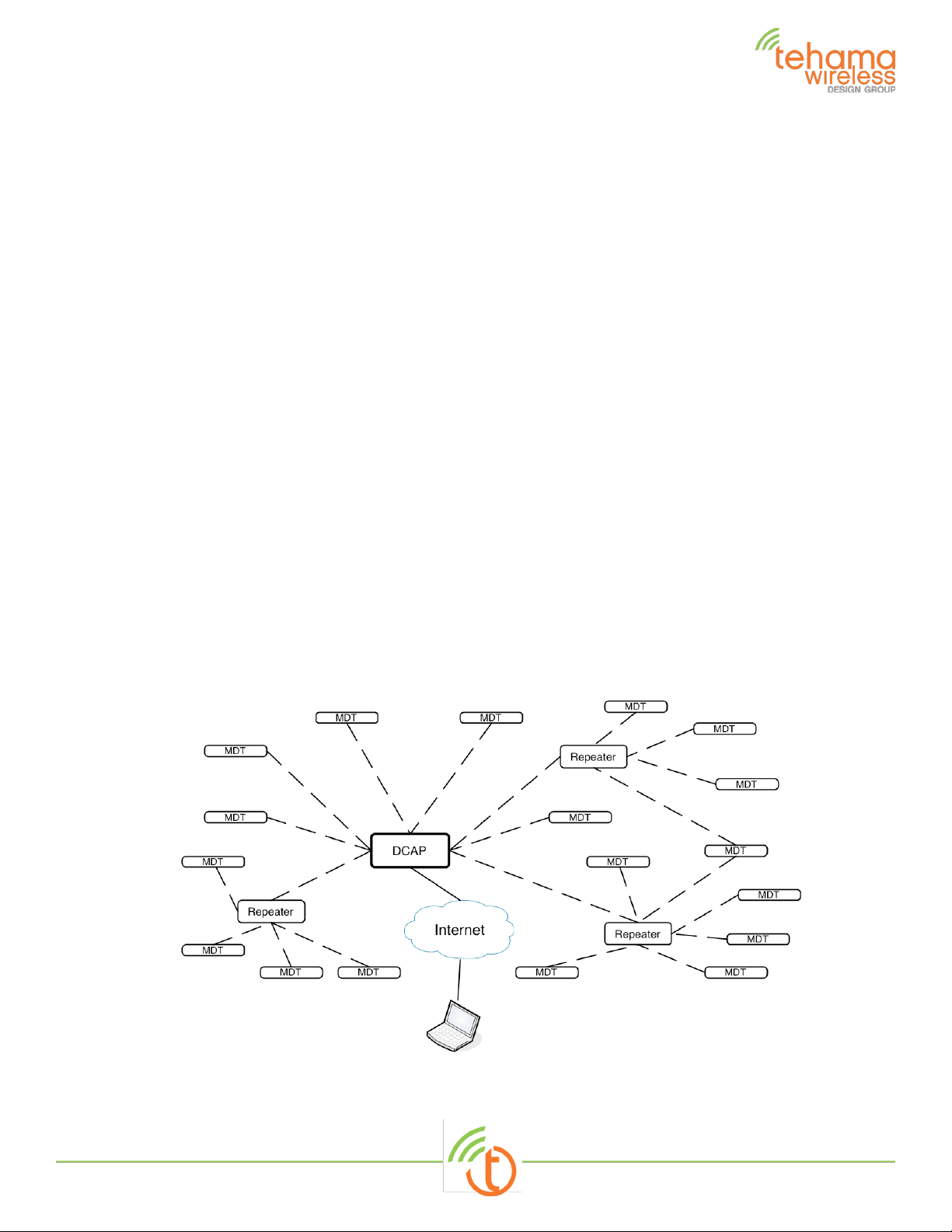
The Tehama AMR system consists of three device types to remotely monitor various
environmental and utility readings and provide the data to a central database or PC for formal
presentation and reporting. Metering Data Transceiver (MDT TW-111, TW-112 and TW113)
devices will be placed in all locations requiring local monitoring of data. The MDT devices will
transmit time stamped data to the DCAP device (DCAP TW-222), which receives the data and
stores it in a Database. The database information is available over Ethernet on the local LAN or
the Internet. For MDTs that are out of range from the DCAP, Repeater devices (RPT TW-222
and TW223) are added in appropriate locations to relay the data between MDTs and the DCAP.
The system operates in the 915MHz ISM bands using off-the-shelf Semtech RFIC radios. The
system operates either as a FHSS over 60 narrow band frequency channels, incorporating a
bidirectional communication link with Acknowledge (ACK) messages to ensure all data reaches
the DCAP or as a DTS non-hopping spread spectrum with 500kHz Bandwidth. The MDTs are
battery operated, bursting data packets at pre-programmed times then shutting down to conserve
battery life, estimated to exceed 5 years. The DCAP and Repeater units are line powered with
the option to power the Repeaters (TW223) with a combination of solar panel and rechargeable
Lithium batteries.
With a typical MDT transmission rate of one per hour (four per hour for Time of Use applications),
a single DCAP can accommodate up to 1000 MDTs. There is no limit to the number of repeaters,
though an average installation where MDTs are spread out in each living space will require one
Repeater for every 20-30 MDT/MDTs.
Figure 1: Typical System
TW113 user guide_REV3.docx 1 of 8
Page 2

NOTE: THE MANUFACTURER IS NOT RESPONSIBLE FOR ANY RADIO OR TV INTERFERENCE
A system consists of two or three types of hardware, and a software program:
A DCAP Unit
•
A variable number of MDT units, each with 2 AA batteries
•
A variable number of Repeater units (optional, depending on size of installation) with
•
external DC power or solar panel supply.
Tehama Configuration Utility (CIT) running on a PC
•
Warning
CAUSED BY UNAUTHORIZED MODIFICATIONS TO THIS EQUIPMENT. SUCH MODIFICATIONS
COULD VOID THE USER
’S AUTHORITY TO OPERATE THE EQUIPMENT
2. Tehama Configuration & Installation Tool (CIT)
You should have received a copy of the Tehama Configuration and Installation Tool (CIT)
software. If not, please contact [email protected]
runs on a Windows based PC. More detailed information can be found in our training class
materials or the Tehama QuickStart Guide available on our
The tool can be run on the PC either prior to or during a site installation, or when new MDTs are
added to a system. The tool is used to add configuration data to the database. Examples of
configuration data include the name, type, and location of equipment an MDT is connected to,
and alarm trigger settings for the different MDTs.
and request the link. The CIT
web site.
3. Data Collecting Access Point (DCAP) Setup
This step configures the Internet settings for the DCAP and lets you set unique passwords for
remote access.
Screw in the Antenna that came with the unit.
•
Power up the DCAP with the supplied power adaptor.
•
Attach the DCAP to your local LAN with the supplied Ethernet cable.
•
Launch the CIT tool on the PC
•
If a static IP or non-default passwords are desired, attach the supplied USB cable to your
•
computer and to the DCAP. If this is the first time attaching to a DCAP, Windows may
respond with a “found new hardware” message. Follow the steps to let Windows download
the driver software. Your PC will need to be connected to the Internet to download the
drivers.
Go to the DCAP -> Configure via USB menu item. The Serial Port field should be
•
automatically populated with the correct COM port
Click on the Get button to see the current settings
•
DCHP (Dynamic IP Address) is the default. If you want a static IP, select static and fill
•
out the extra fields.
TW113 user guide_REV3.docx 2 of 8
Page 3
Set the MySQL database passwords for both users and click “Set”. Clicking on the
•
“Default Vals” button will fill the fields with the factory default passwords. This is
provided as a convenience if password security is not an issue (for example in an
evaluation system).
Click on the “Create a Site Entry” button to auto-fill a Site entry with the information
•
from this panel.
Unplug the USB cable. It is not needed again unless you need to change the IP address
•
or the database passwords at a future time.
4. MDT and Repeater Configuration
All MDT and Repeaters come from the factory with a default factory-set configuration; there is
no user changeable setup. MDTs need only be connected to the meter and turned on. A
number of different MDTs are available, our most popular being a single pulse input unit with a
one-hour transmission interval. See our web site for other variations available.
Standard MDTs
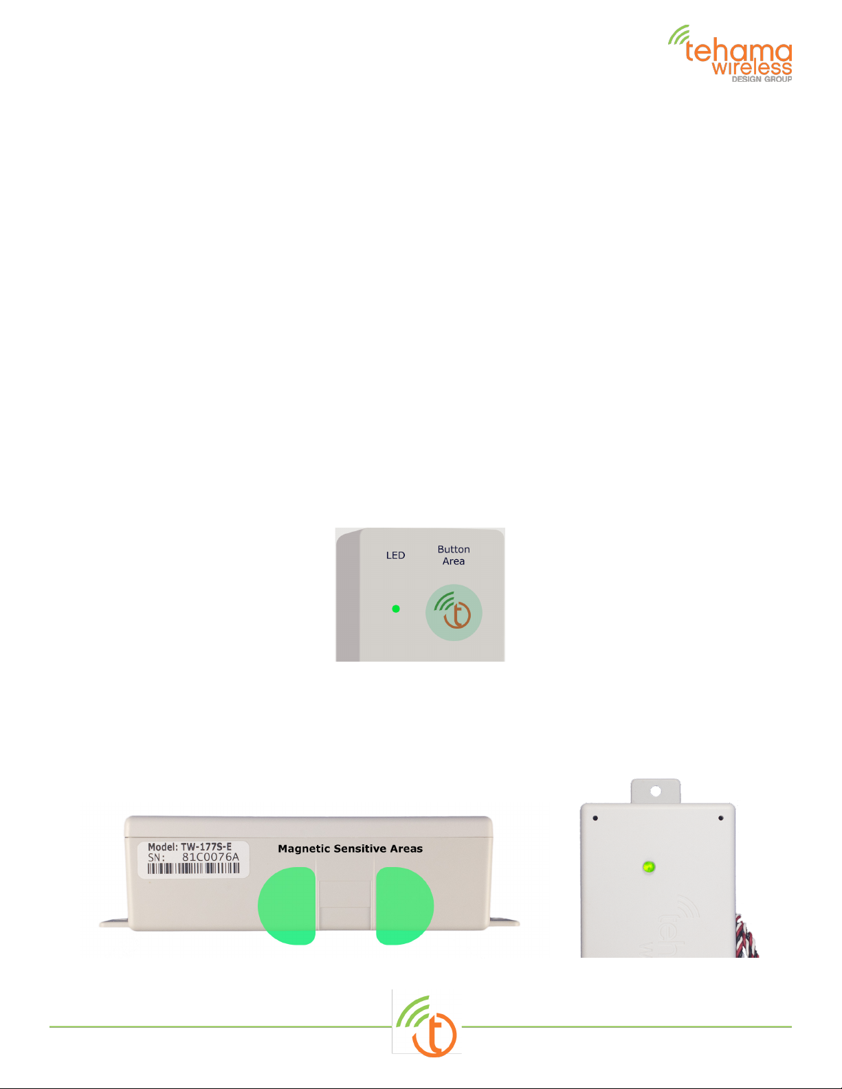
MDT devices come from the factory in a powered off state. They can be powered on using a
hidden button under the Tehama Wireless logo.
The big circle in the photo below shows where the hidden button is located on the enclosure. It
may take a few times to get the feel of the button, but an LED to the left gives you feedback
when the button is pushed.
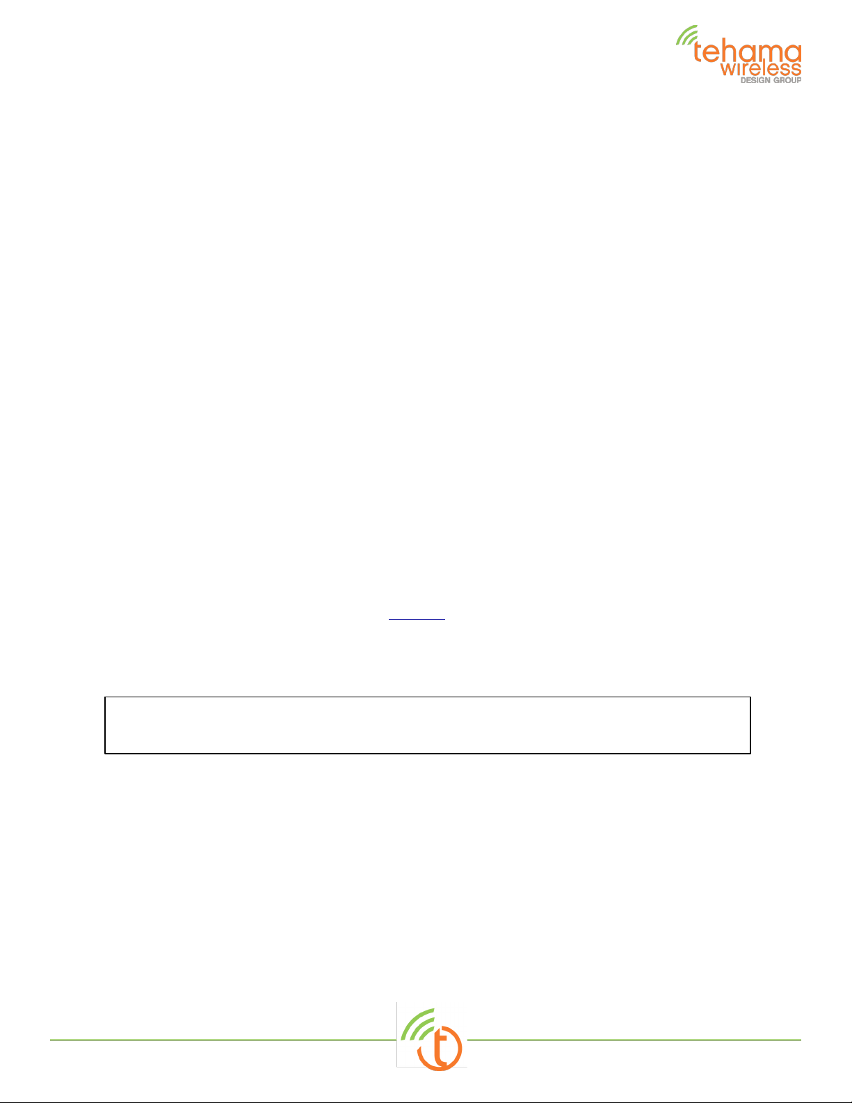
Submersible MDTs TW113
The Submersible MDT operates exactly like our regular MDT. A button press is created by waving
a magnet near the areas shown in the picture below. Status and control are the same as our
regular MDTs, including a “press” to initiate a read and transmit it to the DCAP. The LED on the
top provides the same feedback as our regular LEDs.
TW113 user guide_REV3.docx 3 of 8
Page 4
Warning: All radio devices should be placed at least 8 inches (20 cm) away from people in
Repeaters
The repeaters will automatically power on when power is applied. Press the pushbutton on their
front panel to activate the LEDs as they will turn off eventually to save power.
The information delivered by the LEDs on the MDTs and the Repeaters are identical and
described below:
Turn ON or Off (MDT only):
- Press & hold button until LED blips off, then release.
Power-up LED Flashing:
- Listening for DCAP or Repeater: LED flashes slowly
- Trying to Connect to DCAP: Flashing changes from slow to fast
- Successful Connection: LED stays solid for 10 seconds.
- If NOT successful, LED goes out without the 10 second on
Check the status of an MDT or Repeater by tapping the button
- Unit is OFF: Two flashes after button is released
- Unit is Asleep and NOT connected to Network: One flash only
- Unit will wake up within one hour and try to re-connect to
Network. This is usually an indication of poor placement or
inadequate Repeater coverage.
- Unit is Connected and operating normally: LED on for 10 seconds
- Green is good link, Orange an OK link, Red is poor link
Reset Count (MDT Only): Press and hold button until power-up flashing sequence starts (1215 seconds)
MDT to Meter wiring
Refer to our many wiring diagrams on our web site for wiring instructions from the many
different meters available.
5. Repeaters and MDT Devices Placement
order to minimize RF exposure.
a. Repeaters Backbone
With the DCAP Unit powered up, the repeater backbone should next be placed. Repeaters turn
on automatically when power is applied. Their LEDs will turn off after a few minutes to save
power but can be turned back on by pressing the pushbutton on the front panel. Start with
units closer to the DCAP/AP, and use the LED feedback indication to verify the range is
acceptable. At first just the minimum numbers of repeaters can be placed, and it is necessary
that they be within range (solid 10 second LED “flash” when button pushed) for the backbone
to be reliable. Repeater to Repeater (or DCAP) range in open field scenarios is in excess of 1/2
mile, however building construction materials, terrain, and poor location choices can reduce this
down to hundreds of feet or less.
TW113 user guide_REV3.docx 4 of 8
Page 5
b. MDT placement
Once the initial Repeater placement is complete, the MDT placement phase begins. Again the
LED feedback can be used to verify that MDTs are communicating with the network. Additional
repeaters can be placed in areas where MDTs are unable to connect to the backbone. MDT to
Repeater (or DCAP) range in open field scenarios is in excess of 1500 feet, however building
construction materials, terrain, and poor location choices can reduce this down to a hundred
feet or less.
The CIT software can also be used in the placement phase to provide more detailed information
such as Link Quality and Signal Strength readings generated by MDT and Repeaters.
c. Mounting Guidelines
Units should never be placed directly on a metal surface
on a metal surface will significantly affect the radio performance of the device, be it an MDT or
a Repeater.
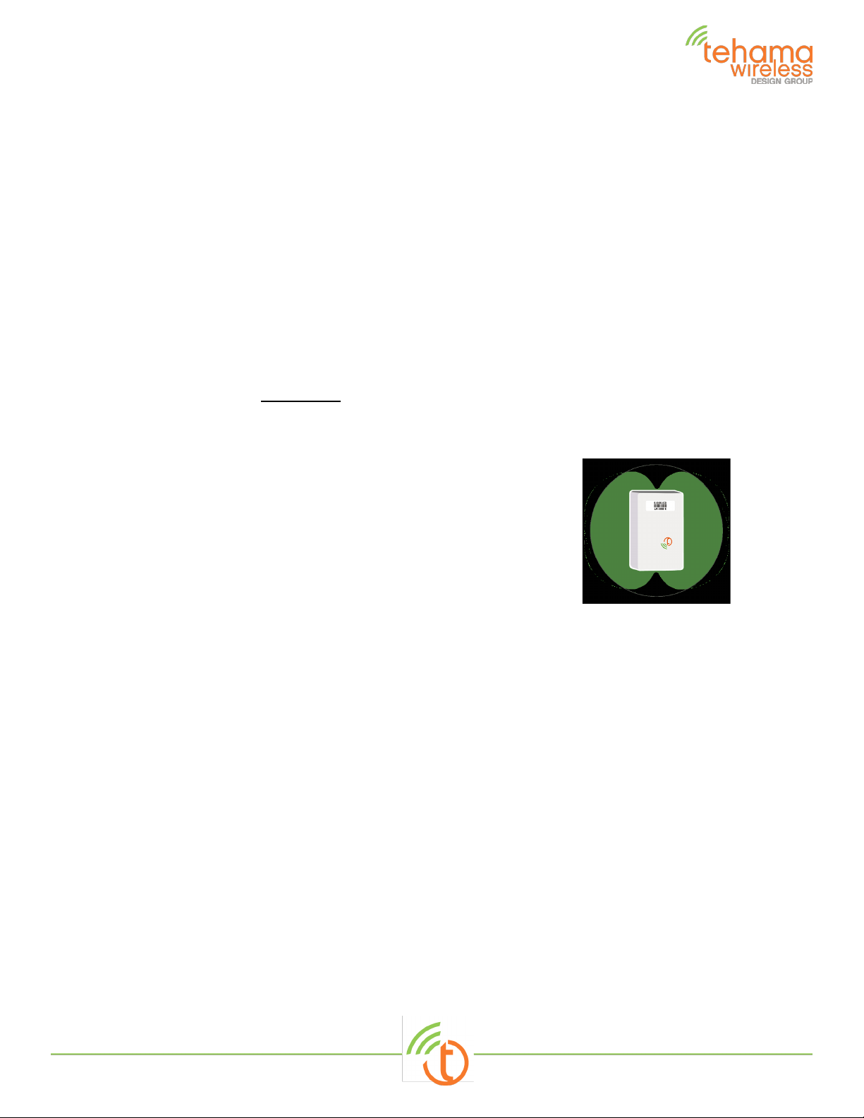
Recommended placement
or within a metal enclosure. Mounting
- Mount on nearby wall away from meter and copper /metal piping
or conduit.
- RF performance is best when mounted on wallboard
- Use keyhole shape to mount on screw in wall
- Designed for #6 Drywall screw
- Separate case to tighten screw if desired
- Note Antenna Pattern shown on the right.
- Radio signal slightly attenuated along the long axis of the MDT
case
TW113 user guide_REV3.docx 5 of 8
Page 6

Users in the US
The device complies with Part 15 of the FCC rules. Operation is subject to the following two conditions:
(1) this device may not cause harmful interference, and
(2) this device must accept any interference received, including interference that may cause
undesired operation
This equipment complies with FCC radiation exposure limits set forth for an uncontrolled environment. The
End user must follow the specific operating instructions for satisfying RF exposure compliance. This
transmitter must not be co-located or operating in conjunction with any other antenna or transmitter.
Changes or modifications not expressly approved by the manufacturer could void the user’s authority to
operate the equipment.
“This equipment has been tested and found to comply with the limits for a Class B digital device,
pursuant to Part 15 of the FCC Rules. These limits are designed to provide reasonable protection against
harmful interference in a residential installation. This equipment generates, uses and can radiate radio
frequency energy and, if not installed and used in accordance with the instructions, may cause harmful
interference to radio communications. However, there is no guarantee that interference will not occur in
a particular installation. If this equipment does cause harmful interference to radio or television
reception, which can be determined by turning the equipment off and on, the user is encouraged to try
to correct the interference by one or more of the following measures:
-- Reorient or relocate the receiving antenna.
-- Increase the separation between the equipment and receiver.
-- Connect the equipment into an outlet on a circuit different from that to which the receiver is
connected.
-- Consult the dealer or an experienced radio/TV technician for help”
Users in Canada
This device contains license-exempt transmitter(s)/receiver(s) that comply with Innovation, Science and
Economic Development (ISED) RSS standard(s). Operation is subject to the following two conditions:
(1) This device may not cause interference, and (2) this device must accept any interference, including
interference that may cause undesired operation of the device.
(2) This equipment complies with ISED radiation exposure limits set forth for an uncontrolled environment
and meets RSS-102 of the ISED radio frequency (RF) Exposure rules. This equipment should be installed
and operated keeping the radiator at least 20cm or more away from person's body (excluding extremities:
hands, wrists, feet and ankles).
Pour les usagers résidant au Canada
Cet appareil contient des émetteurs / récepteurs exemptés de licence conformes aux RSS (RSS)
d’Innovation, Sciences et Développement économique Canada.
L'exploitation est autorisée aux deux conditions suivantes :
(1) L'appareil ne doit pas produire de brouillage, et (2) l'utilisateur de l'appareil doit accepter tout brouillage
radioélectrique subi, même si le brouillage est susceptible d'en compromettre le fonctionnement.
(2) Cet équipement est conforme aux limites d'exposition aux rayonnements énoncées pour un
environnement non contrôlé et respecte les règles d'exposition aux fréquences radioélectriques (RF) CNR102 de l'ISED. Cet équipement doit être installé et utilisé en gardant une distance de 20 cm ou plus entre
le dispositif rayonnant et le corps (à l'exception des extrémités : mains, poignets, pieds et chevilles).
TW113 user guide_REV3.docx 6 of 8
Page 7

Users in the US
The device complies with Part 15 of the FCC rules. Operation is subject to the following two
conditions:
(1) this device may not cause harmful interference, and
(2) this device must accept any interference received, including interference that may
cause undesired operation
This equipment complies with FCC radiation exposure limits set forth for an uncontrolled
environment. The End user must follow the specific operating instructions for satisfying RF
exposure compliance. This transmitter must not be co-located or operating in conjunction with
any other antenna or transmitter. Changes or modifications not expressly approved by the
manufacturer could void the user’s authority to operate the equipment.
“This equipment has been tested and found to comply with the limits for a Class B digital
device, pursuant to Part 15 of the FCC Rules. These limits are designed to provide reasonable
protection against harmful interference in a residential installation. This equipment generates,
uses and can radiate radio frequency energy and, if not installed and used in accordance with
the instructions, may cause harmful interference to radio communications. However, there is
no guarantee that interference will not occur in a particular installation. If this equipment
does cause harmful interference to radio or television reception, which can be determined by
turning the equipment off and on, the user is encouraged to try to correct the interference by
one or more of the following measures:
-- Reorient or relocate the receiving antenna.
-- Increase the separation between the equipment and receiver.
-- Connect the equipment into an outlet on a circuit different from that to which the receiver
is connected.
-- Consult the dealer or an experienced radio/TV technician for help”
FCC/ISED Compliance information for
Users in Canada
This device contains license-exempt transmitter(s)/receiver(s) that comply with Innovation,
Science and Economic Development (ISED) RSS standard(s). Operation is subject to the
following two conditions:
(1) This device may not cause interference, and (2) this device must accept any interference,
including interference that may cause undesired operation of the device.
(2) This equipment complies with ISED radiation exposure limits set forth for an uncontrolled
environment and meets RSS-102 of the ISED radio frequency (RF) Exposure rules. This
equipment should be installed and operated keeping the radiator at least 20cm or more away
from person's body (excluding extremities: hands, wrists, feet and ankles).
Pour les usagers résidant au Canada
Cet appareil contient des émetteurs / récepteurs exemptés de licence conformes aux RSS
(RSS) d’Innovation, Sciences et Développement économique Canada.
L'exploitation est autorisée aux deux conditions suivantes :
(1) L'appareil ne doit pas produire de brouillage, et (2) l'utilisateur de l'appareil doit accepter tout
brouillage radioélectrique subi, même si le brouillage est susceptible d'en compromettre le
fonctionnement.
(2) Cet équipement est conforme aux limites d'exposition aux rayonnements énoncées pour un
environnement non contrôlé et respecte les règles d'exposition aux fréquences radioélectriques
(RF) CNR-102 de l'ISED. Cet équipement doit être installé et utilisé en gardant une distance de
20 cm ou plus entre le dispositif rayonnant et le corps (à l'exception des extrémités : mains,
poignets, pieds et chevilles).
TW113 user guide_REV3.docx 7 of 8
Page 8
MDTs TW-111, TW-112 and TW113 ,
RPT and DCAP TW-222, and RPT TW223
Contact:
Tehama Wireless
2607 7th Street, Suite G
Berkeley, CA 94710
415.495.7344
[email protected]
www.Tehamawireless.com Rev.1903
©2019 Tehama Wireless Design Group
TW113 user guide_REV3.docx 8 of 8
 Loading...