

Page 1
Model:
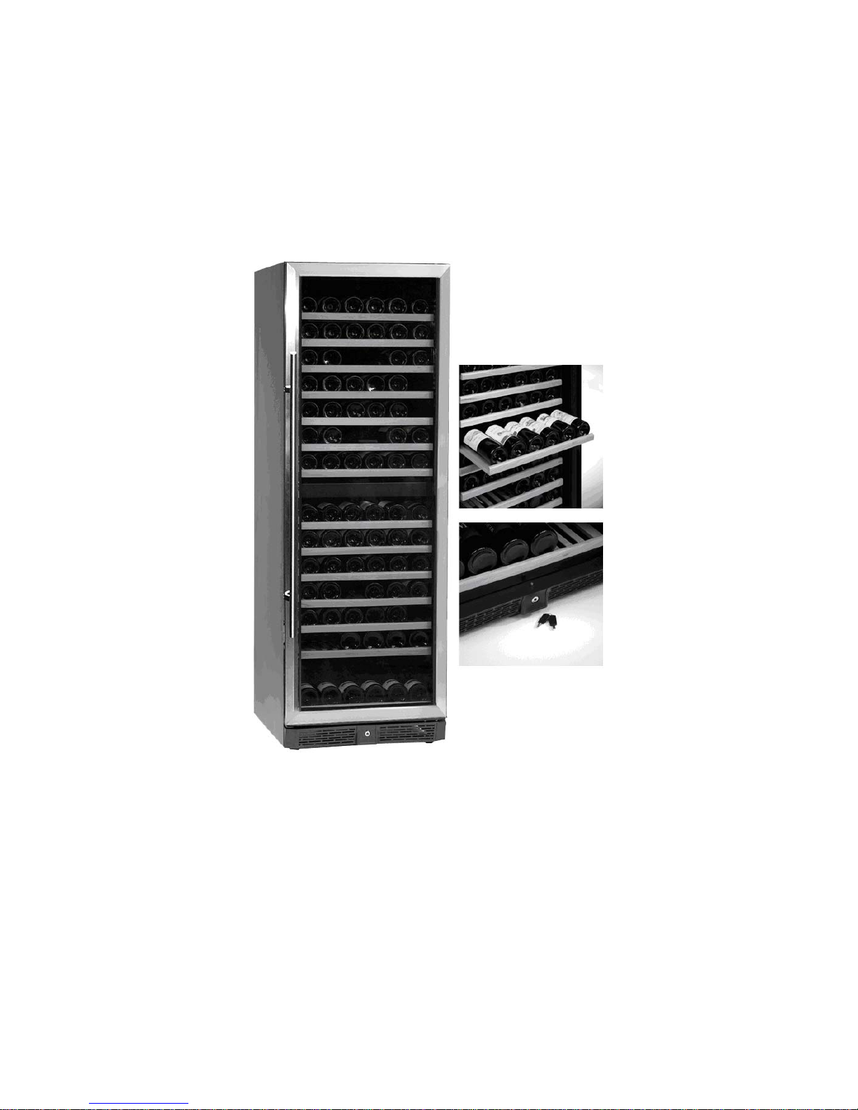
TFW 365-2 / TFW 365-2S
TFW 375 / TFW375S
Brugsvejledning DK 5
Instruction manual UK 14
Bedienungsanleitung D 23
Mode d’emploi F 32
Manuale d’istruzioni
IT 41
Manual de instrucciones ES 50
Manual de Instruções
PT 59
Руководство по эксплуатации RUS 68
1
700-110103
Page 2

DK Indholdsfortegnelse
Vigtige instruktioner 5
Udpakning og opstilling 5
El-tilslutning 6
Opstart 6
Lås 6
Betjening TFW 365-2 7
Betjening TFW 375 8
Indvendig lys 8
Vandbakken 9
Kulfilter 9
Flytning af hylder 9
Vending af dør 10
Vedligeholdelse 11
Service 11
Bortskaffelse 11
UK Contents
Important safety instructions 12
Unpacking and installation 12
Electrical connections 13
Start-up of the cabinet 13
Lock 13
Operation TFW 365-2 14
Operation TFW 375 15
Internal light 15
Water tray 16
Carbon filter 16
Changing position of shelves 16
Door reversal 17
Maintenance and cleaning 18
Service 18
Disposal 18
D Inhalt
Wichtige Sicherheitsvorschriften 19
Auspackung und Aufstellung 19
Anschlieβen 20
Schloss 20
Bedienung TFW 365-2 21
Bedienung TFW 375 22
Innenlicht 22
Wasserback 23
Kohlenfilter 23
Verlagerung die Roste 23
Türwechseln 24
Reinigen 25
Wartung und Kundendienst 25
Entsorgung 25
2
Page 3

F Sommaire
Instructions importantes 26
Désassemblage et mise en place 26
Branchement électrique 27
Démarrage 27
Serrure 27
Manoeuvre TFW 365-2 28
Manoeuvre TFW 375 29
Éclairage intérieure 29
La coupe d’eau 30
Filtre à charbon 30
Ajuster les clayettes 30
Inversion de la porte 31
Entretien 32
Service 32
Mise au rebut 32
IT Contenuto
Istruzioni di sicurezza 33
Disimballaggio e installazione 33
Collegamenti elettrici 34
Avviamento 34
Serratura 34
Funzionamento del modello TFW 365-2 35
Funzionamento del modello TFW 375 36
Illuminazione interna 36
Vaschetta per acqua 37
Filtro al carbonio 37
Spostamento delle griglie 37
Inversione della porta 38
Manutenzione e pulizia 39
Servizio assistenza 39
Smaltimento 39
ES Contenidos
Instrucciones de seguridad importantes 40
Desembalaje e instalación 40
Conexión eléctrica 41
Puesta en marcha del armario 41
Cierre 41
Funcionamiento del modelo TFW 365-2 42
Funcionamiento de modelo TFW 375 43
Luz interna 43
Cubeta para el agua 44
Filtro de carbón 44
Cambiar la posición de los estantes 44
Inversión de la puerta 45
Mantenimiento y limpieza 46
Servicio 46
Eliminación 46
3
Page 4

PT Índice
Instruções importantes de segurança 47
Desembalagem e instalação 47
Ligações Eléctricas 48
Arranque da arca 48
Trancagem 48
Funcionamento TFW 365-2 49
Funcionamento TFW 375 50
Iluminação interna 50
Bandeja de água 51
Filtro de carvão 51
Mudança da posição das prateleiras 51
Inversão da porta 52
Manutenção e Limpeza 53
Serviço 53
Eliminação 53
RUS Содержание
Важная информация 54
Распаковка и установка 54
Подключение к электросети 55
Запуск 55
Замок 55
Эксплуатация TFW 365-2 56
Эксплуатация TFW 375 57
Внутренняя подсветка 57
Емкость для воды 58
Фильтр 58
Переустановка двери 59
Техобслуживание 60
Устранение неполадок 60
Утилизация 60
4
Page 5
DK
Vigtige informationer
1. For at få det fulde udbytte af skabet, bør De læse denne brugsvejledning igennem.
2. Det er brugers ansvar at anvende skabet i henhold til instruktionerne.
3. Kontakt omgående forhandleren, såfremt der opstår fejl ved skabet.
4. Skabet bør anbringes i et tørt og tilstrækkeligt ventileret rum.
5. Skabet bør ikke placeres i nærheden af varmekilder eller direkte sollys.
6. Bemærk at alle elektriske apparater kan medføre arer.
7. Opbevar ikke eksplosionsfarlige stoffer, f.eks. gas, benzin, æter og lignende.
8. Der er ikke brugt asbest eller CFC i konstruktionen.
9. Olien i kompressoren indeholder ikke PCB.
Udpakning og opstilling
Skabet leveres emballeret og på træpalle, fjern dette.
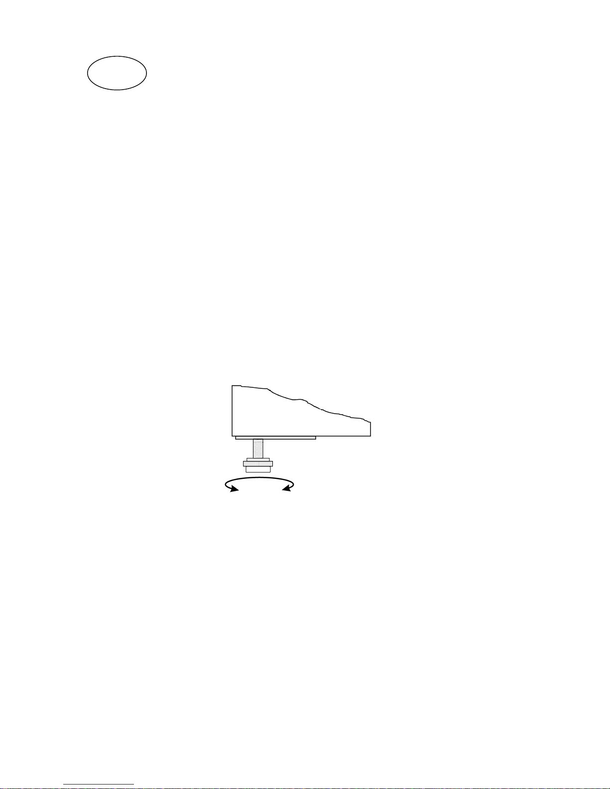
For korrekt funktion er det vigtigt at skabet står lige efter opstilling, dette har fødder der kan
justeres i højde, se fig. 1.1.
Fig. 1.1
Hvis skabet indbygges, er man nødt til at tage hensyn til følgende:
1. Der skal være en passende luftsprække over skabet, mindst 10 cm., for at kølesystemet kan
fungere tilfredsstillende.
2. Afstand til vægge o.lign. i hængselsiden skal være af passende størrelse, så man kan udskifte
hylder og rengøre ved hængslet.
5
Page 6
El-tilslutning
Skabet er beregnet for tilslutning til 220-240 V/50 Hz. Tilslutningen skal ske ved en stikkontakt, der
bør være let tilgængelig.
Dette kølemøbel skal ekstrabeskyttes ifølge stærkstrømsreglementet. Dette gælder også, selvom der
er tale om udskiftning af et eksisterende kølemøbel, der ikke har været ekstrabeskyttet. I bygninger
opført før 1. april 1975 er ekstrabeskyttelsen i orden, hvis der er installeret HFI-afbryder, som
beskytter den stikkontakt skabet skal tilsluttes.
I begge disse tilfælde skal der, hvis stikkontakten er for trebenet stikprop, benyttes en trebenet
stikprop, og lederen med grøn/gul isolation skal tilsluttes jordklemmen (mærket ).
Hvis stikkontakten kun er for tobenet stikprop, benyttes en tobenet stikprop. Hvis brugeren selv
monterer denne, skal lederen med grøn/gul isolation klippes af så tæt som muligt på det sted, hvor
lederen går ind i stikproppen.
I alle andre tilfælde bør De lade en autoriseret el-installatør undersøge, hvordan De nemmest får
ekstrabeskyttet skabet. Hvis De ikke har ekstrabeskyttelse i bygningen i forvejen, anbefaler
Elektricitetsrådet, at De lader el-installatøren opsætte en PFI- eller HPFI afbryder.
Opstart
Inden skabet tages i brug, anbefales det at rengøre dette, se afsnit om vedligeholdelse.
Vigtigt !
Hvis skabet har ligget ned under transport, vent 2 timer før opstart.
For at skabet skal fungere optimalt må den omgivende temperatur ikke være under 18 ºC og ikke
over 35 ºC.
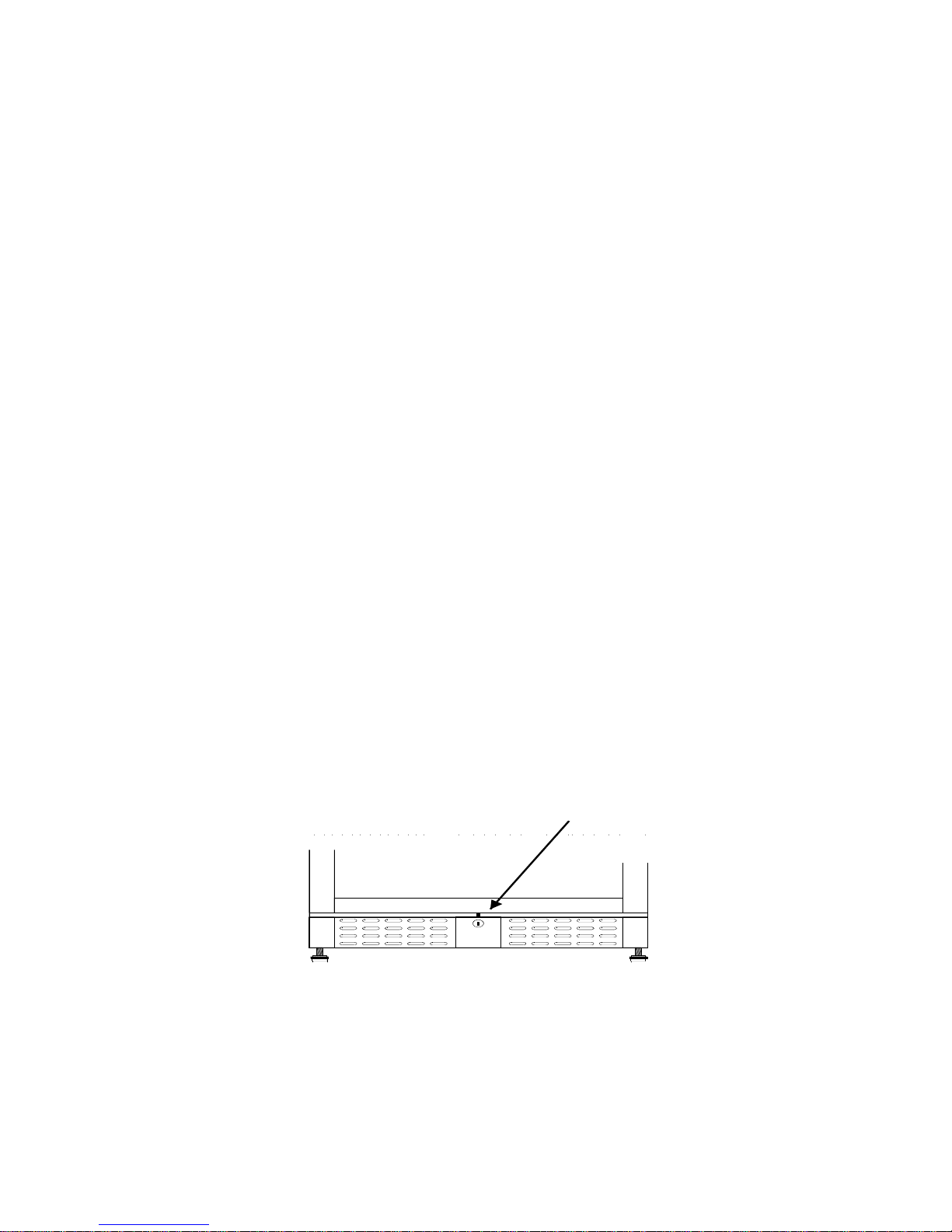
Lås
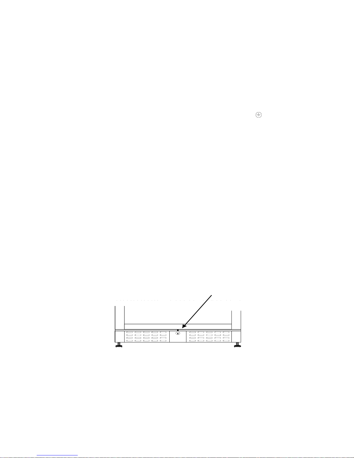
Skabet er forsynet med en lås, denne er placeret i bundpanel, se fig. 1.2.
Fig. 1.2
6
Page 7
Betjening model TFW 365-2
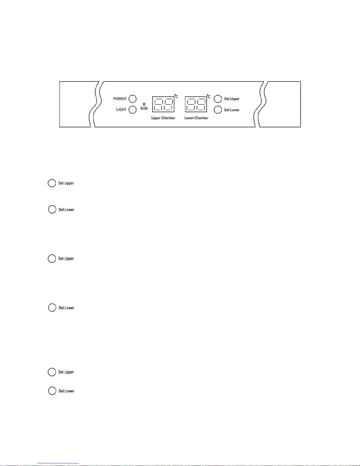
Tilslut skabet til stikkontakt og tænd for kontakten (POWER) på kontrolpanel, se fig. 1.9.
Fig. 1.9
Når skabet tændes vil display vise de aktuelle temperaturer i skabets 2 sektioner.
Kontrollampen ’Run’ vil tænde.
Vis indstillet temperatur:
Tryk på denne tast og display vil blinke med den indstillede temperatur for
øverste sektion, efter 5 sec. vil termostaten vende tilbage til normal visning.
Tryk på denne tast og display vil blinke med den indstillede temperatur for
nederste sektion, efter 5 sec. vil termostaten vende tilbage til normal visning.
Indstil ny temperatur:
Tryk på denne tast og display vil blinke med den nuværende indstilling.
Hvert tryk herefter vil sænke indstillingen med 1 ºC, fra 12 ºC til 5 ºC og derefter forfra.
Når den ønskede temperatur er fundet, afvent i 5 sec. hvorefter termostaten vender
tilbage til normal visning.
Tryk på denne tast og display vil blinke med den nuværende indstilling.
Hvert tryk herefter vil sænke indstillingen med 1 ºC, fra 18 ºC til 12 ºC og derefter
forfra.
Når den ønskede temperatur er fundet, afvent i 5 sec. hvorefter termostaten vender
tilbage til normal visning.
Vis temperatur i ºC/ºF:
+
Tryk på disse taster samtidigt i 5 sec. og udlæsning af temperaturer vil skifte
mellem Fahrenheit og Celsius.
7
Page 8
Betjening model TFW 375
Tilslut skabet til stikkontakt og tænd for kontakten (POWER) på kontrolpanel, se fig. 2.0.
Fig. 2.0
Når skabet tændes vil display vise den indstillede samt den aktuelle temperatur i skabet.
Indstil ny temperatur:
Tryk på denne tast og indstillet temperatur vil øges med 1 ºC for hvert tryk.
Tryk på denne tast og indstillet temperatur vi sænkes med 1 ºC for hvert tryk.
Vis temperatur i ºC/ºF:
+ Tryk på disse taster samtidigt i 5 sec. og udlæsning af temperaturer vil skifte
mellem Fahrenheit og Celsius.
Indvendigt lys:
Tryk på denne tast vil tænde/slukke det indvendige lys.
8
Page 9
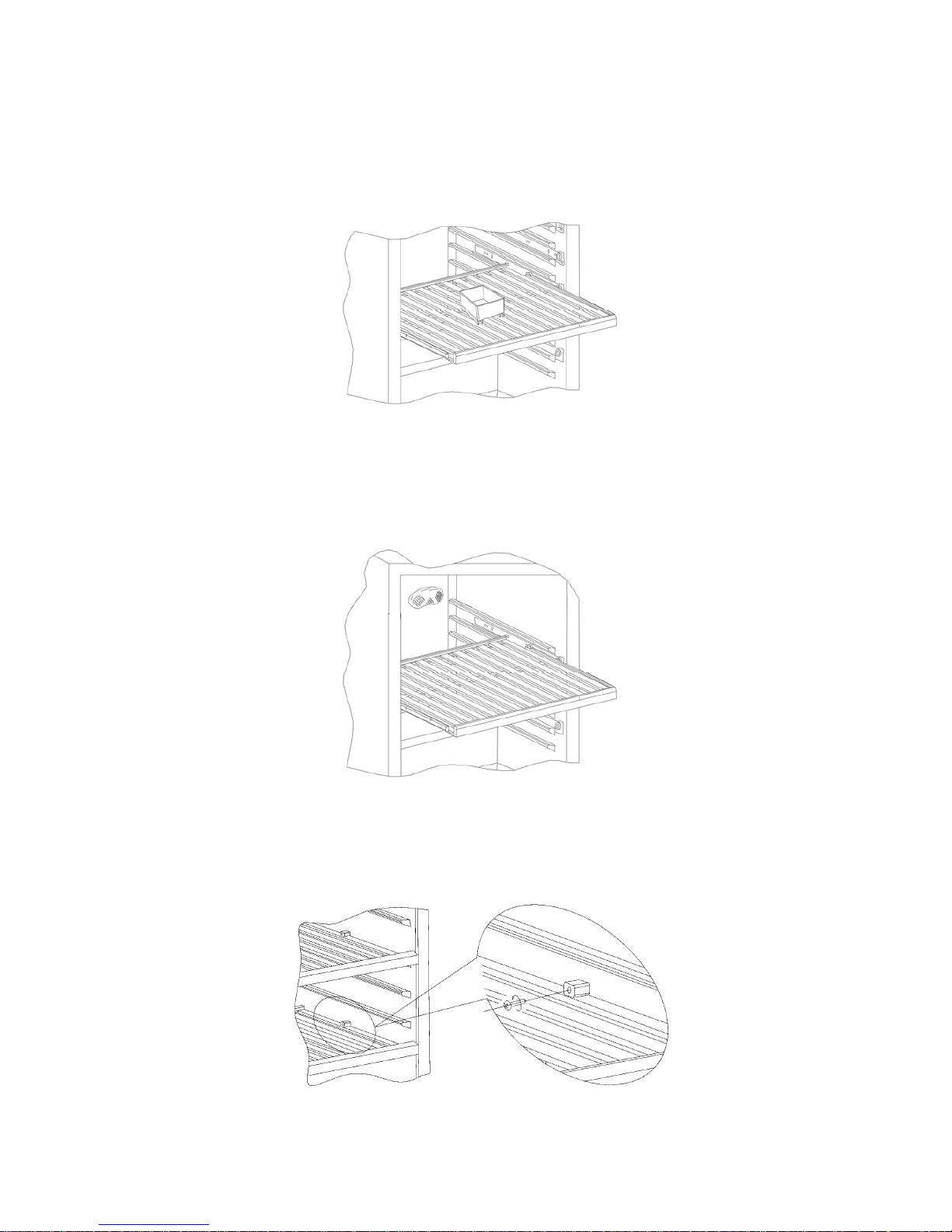
Vandbakken
For at forhindre udtørring af vinpropperne p.g.a. lav luftfugtighed, er skabet forsynet med en
vandbakke der bør placeres på øverste hylde, se fig. 1.3.
Fig. 1.3
Kulfilter
Skabet er forsynet med et kulfilter der modvirker dårlig lugt, dette er placeret bagerst i skabet, se
fig. 1.4.
Fig. 1.4
Flytning af hylder
Fjern begge stopklodser, disse er monteret med en stjerneskrue, træk derefter hylden ud, se fig. 2.2.
Fig. 2.2
9
Page 10
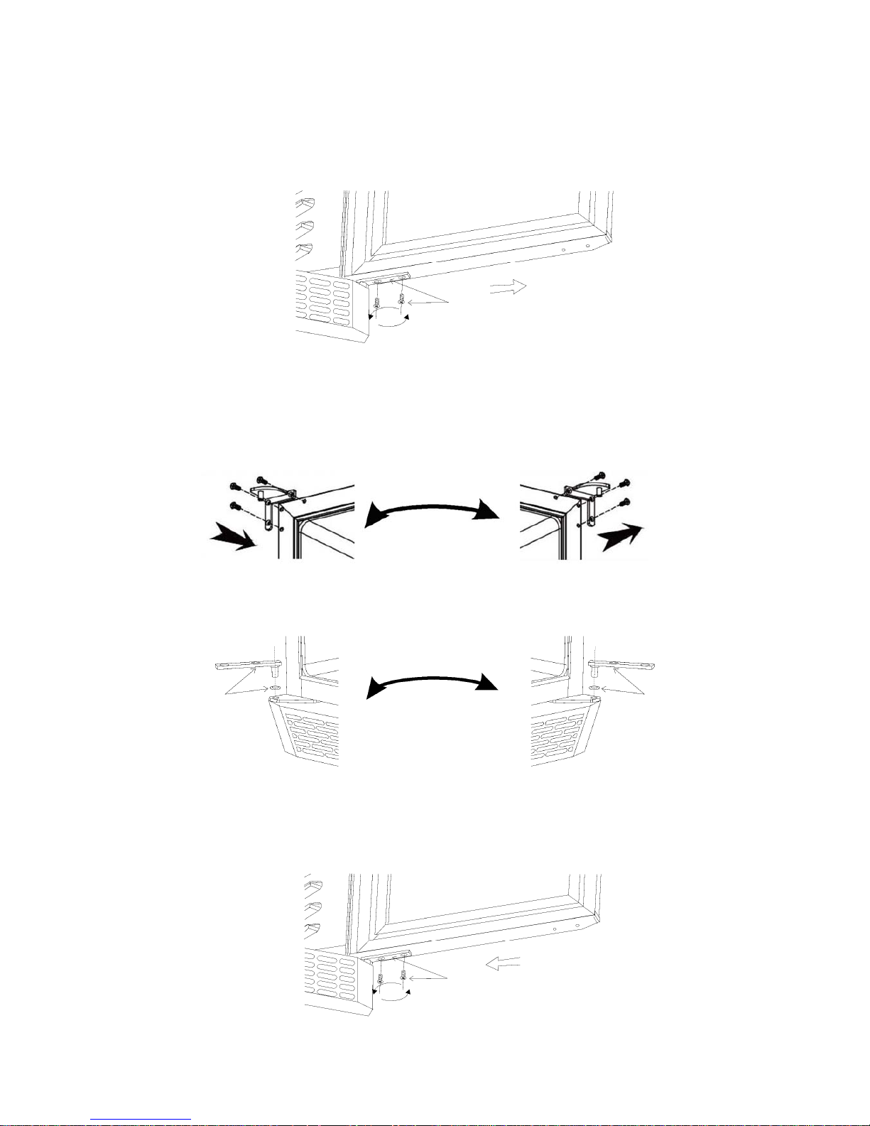
Vending af dør
Døren åbnes og de 2 skruer i bundhængsel fjernes og døren løftes ud, se fig. 2.4.
Fig. 2.4
Tophængsel flyttes til modsatte side, se fig. 2.5.
Fig. 2.5
Bundhængsel flyttes til modsatte side, se fig. 2.6.
Fig. 2.6
Døren sættes på bundhængsel og skruerne monteres igen, se fig. 2.7.
Fig. 2.7
10
Page 11

Vedligeholdelse
Afbryd skabet på stikkontakten.
Med passende mellemrum skal skabet rengøres. Udvendig og indvendige rengøring foretages med
svag sæbeopløsning og aftørres grundigt. Udvendige overflader kan vedligeholdes med stålolie.
Rengøringsmidler må IKKE indeholde klor, klorforbindelser eller andre aggresive midler, da de kan
forårsage tæringer på de rustfri flader og på det indvendige kølesystem.
Ventilationsristen holdes bedst rent ved hjælp af en støvsuger og en stiv børste.
Der må ikke spules med vand ind i kompressorrummet, da der kan opstå kortslutninger og skader på
de elektriske dele.
Service
Kølesystemet er et hermetisk lukket system og kræver ikke tilsyn, kun renholdelse.
Ved svigt i kølevirkningen, undersøg om årsagen er afbrydelse i stikkontakt eller sikringsgruppe.
Kan grunden til svigt ikke findes, må De henvende Dem til Deres leverandør. Ved al henvendelse
bedes De oplyse skabets typenavn og serienummer. Disse oplysninger findes på typenummerskiltet
placeret bag på skabet i venstre side.
Bortskaffelse
Når det udtjente kølemøbel skal bortskaffes, skal det ske på en miljømæssig forsvarlig måde. Vær
opmærksom på reglerne for bortskaffelse. Der kan være særlige krav og betingelser, der skal
overholdes.
11
Page 12

UK
Important safety instructions
1. To obtain full use of the cabinet, we recommend reading this instruction manual.
2. It is the user’s responsibility to operate the appliance in accordance with the instructions
given.
3. Contact your dealer immediately in case of any malfunctions.
4. Place the cabinet in a dry and ventilated place.
5. Keep the cabinet away from strongly heat-emitting sources and do not expose it to direct
sunlight.
6. Always keep in mind that all electrical devices are sources of potential danger.
7. Do not store inflammable material such as thinner, gasoline etc. in the cabinet.
8. We declare that no asbestos nor any CFC are used in the construction.
9. The oil in the compressor does not contain PCB.
Unpacking and installation
Remove the wooden pallet and the packing.
To ensure correct function it is important that the cabinet is level. The cabinet is supplied with legs,
which can be adjusted. See fig. 1.1.
Fig. 1.1
If you want to build in your cabinet please note the following:
1. There must be at least 10 cm free space above the cabinet in order for the cooling system to
work satisfactorily.
2. There must be sufficient space at the hinge side to clean and replace the shelves and clean
around the hinge.
12
Page 13
Electrical connecting
The cabinet operates on 230 V/50 Hz.
The wall socket should be easily accessible.
All earthing requirements stipulated by the local electricity authorities must be observed. The
cabinet plug and wall socket should then give correct earthing. If in doubt, contact your local
supplier or authorized electrician.
The flexible cord fitted to this appliance has three cores for use with a 3-pin 13-Amp or 3-pin 15Amp plug. If a B.S. 1363 (13-Amp) fused plug is used, it should be fitted with a 13-Amp fuse.
The wires in this mains lead are coloured in accordance with the following code:
Green/Yellow: Earth, Blue: Neutral, Brown: Live.
The main electrical connections must be done by skilled electricians.
Start-up of the cabinet
Before use, we recommend that the cabinet is cleaned, see the section on maintenance and cleaning.
Important !
If the cabinet has been horizontally placed during transport, please wait 2 hours before starting up
the cabinet.
In order to ensure optimum function of the cabinet the ambient temperature must be between 18 and
35 ºC.
Lock
The cabinet is provided with a lock, which is placed in the bottom panel, see fig. 1.2.
Fig. 1.2
13
Page 14
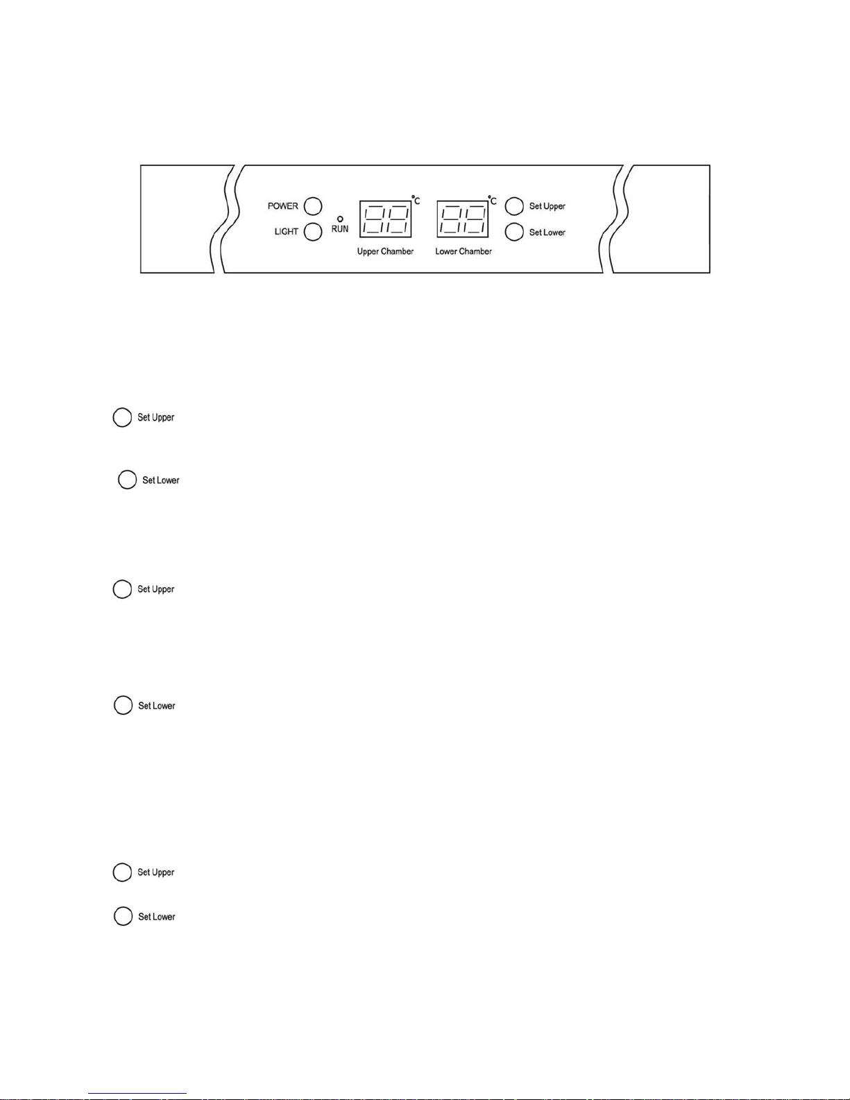
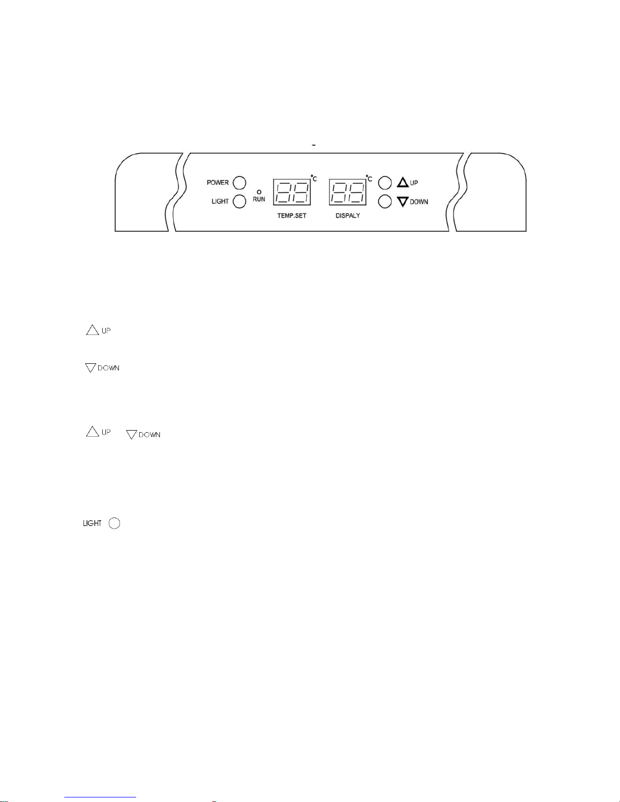
Operation model TFW 365-2
Connect the cabinet to a socket and turn on the switch on the control panel (POWER), see fig. 1.9.
Fig. 1.9
When the cabinet is turned on, the display will show the current temperatures in the cabinet’s two
chambers.
Control lamp ”Run” will turn on.
Display set temperature:
Press this key and the display will flash the set temperature for the upper chamber.
After 5 seconds the thermostat will return to normal reading.
Press this key and the display will flash the set temperature for the lower chamber.
After 5 seconds the thermostat will return to normal reading.
Set new temperature:
Press this key and the display will flash the set temperature.
Every subsequent press on this key will lower the setting by 1 ºC, from 12 ºC to 5 ºC and
will start over again after that.
When the required temperature is reached, wait for 5 seconds and the thermostat will
return to normal reading.
Press this key and the display will flash the set temperature.
Every subsequent press on this key will lower the setting by 1 ºC, from 18 ºC to 12 ºC
and will start over again after that.
When the required temperature is reached, wait for 5 seconds and the thermostat will
return to normal reading.
Display temperature in ºC/ºF:
+
Press these keys simultaneously for 5 seconds and display of temperature will
change between Fahrenheit and Celsius.
14
Page 15
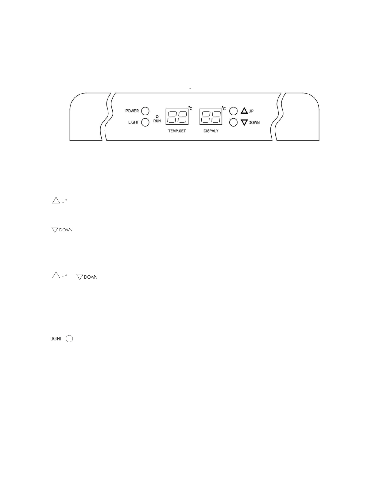
Operation model TFW 375
Connect the cabinet to a socket and turn on the switch on the control panel (POWER), see fig. 2.0.
Fig. 2.0
When the cabinet is turned on, the display will show the current temperature in the cabinet.
Set new temperature:
Press this key and the set temperature will increase by 1°C for each pressure.
Press this key and the set temperature will decrease by 1ºC for each pressure.
Display temperature in ºC/ºF:
+
Press these keys simultaneously for 5 seconds and display of temperature will
change between Fahrenheit and Celsius.
Internal light:
Press this key to turn on/off the internal light.
15
Page 16
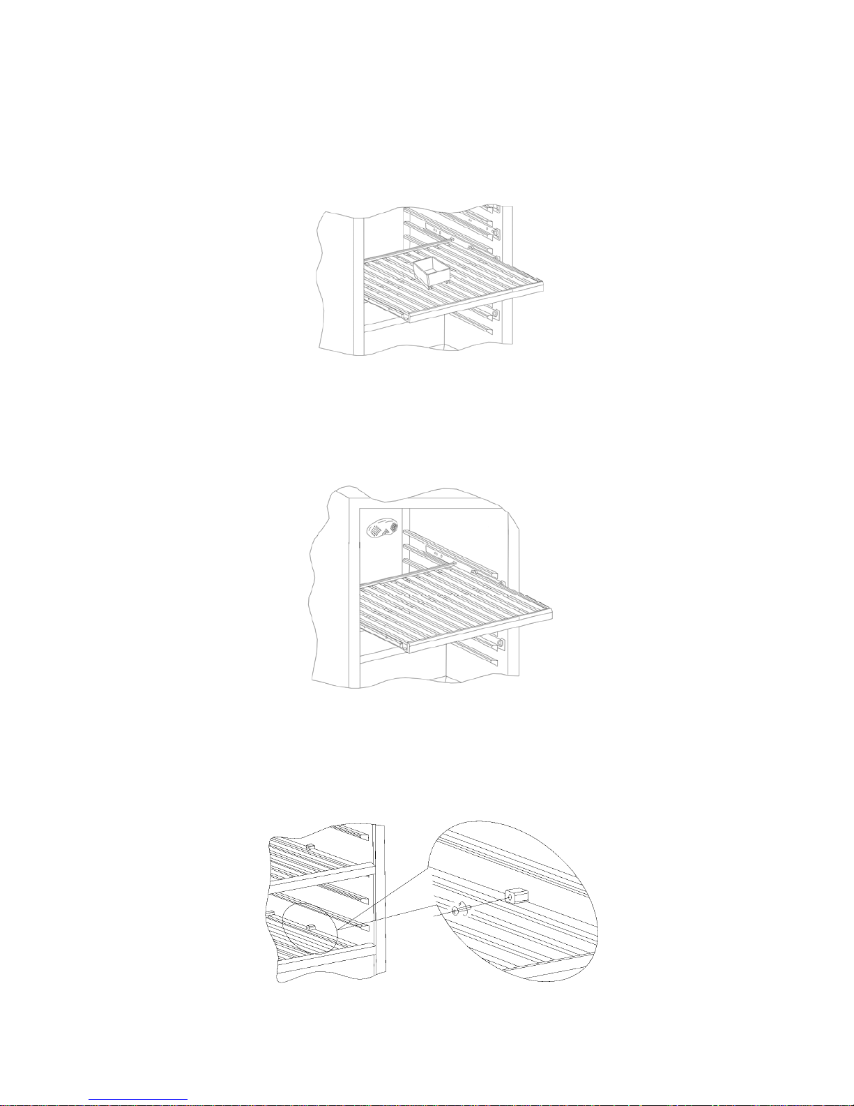
Water tray
In order to prevent drying up of the wine corks due to low humidity the cabinet is supplied with a
water tray, which should be placed at the top shelf, see fig. 1.3.
Fig. 1.3
Carbon filter
The cabinet is supplied with a carbon filter to prevent bad smell. This is placed at the rear wall
inside the cabinet, see fig. 1.4.
Fig. 1.4
Changing position of shelves
Remove both stop blocks which are mounted with a cross-point screw. Then pull out the shelf, see
fig. 2.2.
Fig. 2.2
16
Page 17
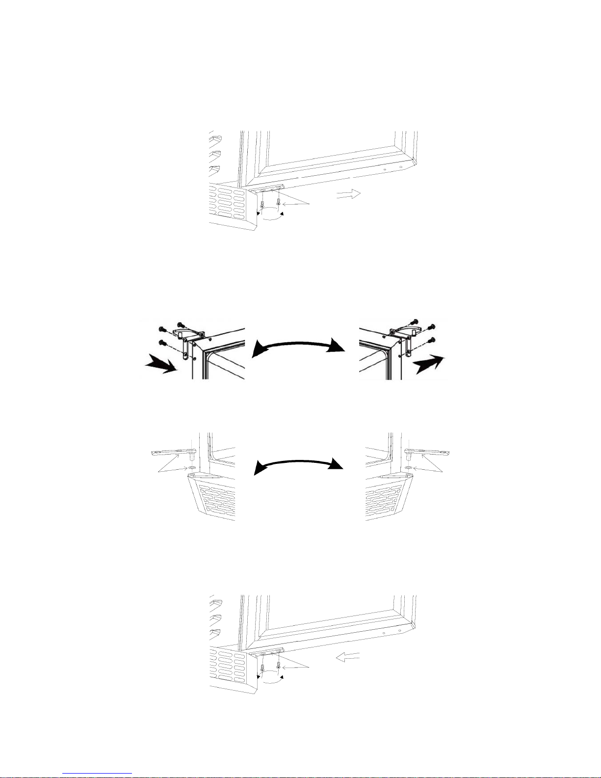
Door reversal
Open the door, remove the two screws in the bottom hinge and lift out the door, see fig. 2.4.
Fig. 2.4
Move the the top hinge to the opposite side, see fig. 2.5.
Fig. 2.5
Move the bottom hinge to the opposite side, see fig. 2.6.
Fig. 2.6
Replace the door on the bottom hinge and mount the screws again, see fig. 2.7.
Fig. 2.7
17
Page 18

Maintenance and cleaning
Switch the cooler off at the socket.
The cabinet must be periodically cleaned. Clean the external and internal surfaces of the cabinet
with a light soap solution and subsequently wipe dry. External surfaces can be maintained using
steel oil.
Keep the fan cover clean by using a vacuum cleaner and a stiff brush.
Do NOT use cleansers containing chlorine or other harsh cleansers, as these can damage the
stainless steel surfaces and the internal cooling system.
Do NOT hose the compressor compartment with water as this can cause short circuits and damage
on the electrical parts.
Service
The cooling system is a hermetically sealed system and does not require supervision, only cleaning.
If the cabinet fails to cool, check if the reason is a power cut.
If you cannot locate the reason to the failure of the cabinet, please contact your supplier. Please
inform model and serial number of the cabinet. You can find this information on the rating label
which is placed on the back side of the cabinet on the left hand side.
Disposal
Disposal of the cabinet must take place in an environmentally correct way. Please note existing
regulation on disposal. There may be special requirements and conditions which must be observed.
18
Page 19

D
Wichtige Sicherheitsvorschriften
1. Vor Inbetriebnahme sollten Sie diese Gebrauchsanweisung ganz durchlesen, damit Sie das
Gerät voll ausnutzen können.
2. Es ist wichtig alle Vorschriften zu folgen bei Anwendung des Schrankes.
3. Im Falle einer Störung kontaktieren Sie bitte daher umgehend Ihren Fachhändler.
4. Platzieren Sie den Schrank an einem trockenen und ventilierten Standort.
5. Der Schrank darf nicht in der Nähe von Hitzeabstrahlenden Geräten (z.B. Küchenherd/-
ofen) platziert werden. Vermeiden Sie Standorte mit direkter Sonneneinstrahlung.
6. Bitte denken Sie daran, dass alle elektrischen Geräte gefährlich sein können.
7. Bewahren Sie keine explosiven Stoffe wie z.B. chemische Verdünnungsmittel, Benzin und
Äther in diesem Gerät.
8. Wir erklären, dass kein Asbest noch CFC im Aufbau verwendet worden ist.
9. Das Öl im Kompressor enthält nicht PWB.
Auspackung und Aufstellung
Der Schrank wird auf einer Holzpalette für den sicheren Transport geliefert. Entfernen Sie diese.
Für korrekte Funktion stellen Sie den Schrank in einer geraden/waagrechten Position auf. Richten
Sie bitte den Kühlschrank mit Hilfe der Stellfüße aus. Sehe Fig. 1.1.
Fig. 1.1
Bitte beachten Sie unbedingt folgende Einbauhinweise:
1. Es müssen mindestens 10 cm oberhalb des Gerätes frei gehalten werden damit das
Kühlsystem ordnungsgemäß funktioniert.
2. Achten Sie auf genügend Freiraum an der Seite des Scharnier-/Türanschlages um das Gerät
reinigen und die Roste/Einlegeböden ersetzen bzw. entnehmen zu können.
19
Page 20

Elektrischer Anschluss
Das Gerät hat eine Spannung von 230V/50Hz. Die Netzsteckdose darf zugänglich sein.
Erstmalige Inbetriebnahme
Schrank außen und innen reinigen, Sehe Abschnitt wegen Reinigung.
Wichtig!
Falls der Schrank liegend transportieret ist, warten Sie 2 Stunden vor Anschluss.
Um optimale Funktion zu erreichten die Umgebungstemperatur unter 18°C und nicht über 35°C
sichern.
Schloss
Der Schrank ist mit einem Schloss im Bodenpaneel montieret, sehe Fig. 1.2.
Fig. 1.2
20
Page 21

Bedienung Modell TFW 365-2
Netzstecker in die Steckdose stecken und Schalter (POWER) auf Kontrollpaneel einschalten, sehe
Fig. 1.9
Fig. 1.9
Wenn der Schrank eingeschaltet ist, zeigt die Lichtdiode die aktuelle Temperatur in den zwei
Sektionen.
Die Kontrollampe „run“ schaltet ein.
Zeigen die eingestellte Temperatur:
Drücken Sie auf diesen Taster und LED blinkt mit der eingestellte Temperatur für
obere Sektion. Nach 5 Sekunden geht der Thermostat zurück auf normale Funktion
zurück.
Drücken Sie auf diesen Taster und LED blinkt mit der eingestellte Temperatur für
untere Sektion. Nach 5 Sekunden geht der Thermostat auf normale Funktion zurück.
Neue Temperatur einstellen:
Drücken Sie auf dieser Taste und LED blinkt mit der aktuellen Einstellung.
Jeder Druck darauf senkt die Temperatur mit 1°C, von 12°C bis 5°C und danach von
vorne.
Wenn die gewünschte Temperatur gefunden ist, warten Sie 5 Sekunden und der
Thermostat geht auf normale Funktion zurück.
Drücken Sie auf dieser Taste und LED blinkt mit der aktuellen Einstellung.
Jeder Druck darauf senkt die Temperatur mit 1°C, von 18°C bis 12°C und danach von
vorne. Wenn die gewünschte Temperatur gefunden ist, warten Sie 5 Sekunden und der
Thermostat geht auf normale Funktion zurück.
Zeigen Temperatur in C°/F°:
+
Drücken Sie auf diese Taster gleichzeitig, warten 5 Sekunden und LED zeigt
Fahrenheit und Celsius abwechselnd.
21
Page 22

Bedienung Modell TFW375
Netzstecker in die Steckdose stecken und Schalter (POWER) auf Kontrollpaneel einschalten, sehe
Fig. 2.0.
Fig. 2.0
Wenn der Schrank eingeschaltet ist, Lichtdiode zeigt die eingestellte und aktuelle Temperatur im
Schrank.
Neue Temperatur einstellen:
Drücken Sie auf diesen Taster und die eingestellte Temperatur wird mit 1°C erhöht für
jeden Druck.
Drücken Sie auf diesen Taster und die eingestellte Temperatur wird mit 1°C gesenkt für
jeden Druck.
Zeigen Temperatur in C°/F°:
+
Drücken Sie auf diese Taster gleichzeitig, warten 5 Sekunden und LED zeigt
Fahrenheit und Celsius abwechselnd.
Innenlicht
Drücken Sie auf diesen Taster und die Innenlicht schaltet ein.
22
Page 23

Wasserback
Um Austrocknen der Weinpropfens zu vermeiden wegen einer niedrigen Luftfeuchtigkeit, ist der
Schrank mit einer Wasserback geliefert. Diese sollt auf der oberen Roste platziert sein, sehe Fig. 1.3
Fig. 1.3
Kohlenfilter
Der Schrank ist mit einem Kohlenfilter geliefert um schlechtes Geruch zu vermeiden. Der
Kohlenfilter ist ganz hinten im Schrank montiert, sehe Fig. 1.4.
Fig. 1.4
Verlagerung die Roste
Beige Stoppklötze entfernen, diesen sind mit einer Sternschraube montiert, dann die Roste
ausziehen, sehe Fig. 2.2.
Fig. 2.2
23
Page 24

Türwechseln
Die Tür öffnen und de 2 Schrauben im Bodenscharnier entfernen, dann die Tür entfernen, sehe Fig.
2.4.
Fig. 2.4
Angelzapfen im Obenscharnier auf der anderen Seite montieren, sehe Fig. 2.5.
Fig. 2.5
Bodenscharnier auf der anderen Seite montieren, sehe Fig. 2.6.
Fig. 2.6
Die Tür auf das Scharnier platzieren und die Schrauben wieder montieren, sehe Fig. 2.7.
Fig. 2.7
24
Page 25

Reinigung und Pflege
Schalten Sie das Gerät ab und Netzstecker ausziehen. Innen und außen mit mildem
Geschirrspülmittel reinigen und nachtrocken. Außenflächen eventuell mit Stahlöl behandeln.
Verwenden Sie keine chemischen Reinigungsmittel mit Inhalt von Chlor, Chlorverbindungen oder
andere aggressive Mitteln, weil diese Rostfraß auf die Edelstahlflächen und das Innenkühlsystem
verursachen können.
Die Belüftungsgitter mit einer steifen Bürste oder mit dem Staubsauger reinigen.
Achten Sie darauf das Kompressorraum nicht zu spülen um Schaden auf die elektrische Teile zu
vermeiden.
Kundendienst
Das Kühlsystem ist ein hermetisch geschlossenes System und fordert kein Kundendienst nur
Reinigung.
Störungen
Bei Störungen der Kühlung untersuchen Sie
Wenn der Kompressor immer noch läuft bitte überprüfen Sie, ob der Stecker richtig in der
Netzsteckdose. Wenn es nicht möglich ist die Störung zu finden, wenden Sie sich bitte an den
Lieferanten. Bei Kundendienst müssen Sie das Typ des Schrankes und Serienummer angeben.
Typenschild innen im Schrank an der linken Seite gibt alle Informationen.
Entsorgung
Wenn der Schrank wegzuwerfen ist, wird sie gemäß geltender Vorschrift entsorgt. Sie müssen
vielleicht bestimmte Ansprüche und Bedingungen beachten.
25
Page 26

F
Instructions importantes
1. Avant d’utiliser votre armoire, nous vous recommandons de lire attentivement ce mode
d’emploi.
2. L’utilisateur se doit d’utiliser l’appareil selon les instructions données.
3. Contacter votre revendeur immédiatement en cas de défaut de fonctionnement de l’armoire.
4. L’armoire doit être placée dans un endroit sec et ventilé.
5. L’armoire ne doit pas être exposée aux rayons du soleil ou à toute autre source de chaleur.
6. N’oubliez pas que tous les appareils électriques sont des sources de danger potentiel.
7. Dans l’armoire ne conservez pas et n’utilisez pas de produits inflammables ou susceptibles
de provoquer des explosions, tels que gaz, briquets, essence, éther etc.
8. Aucun asbeste ou CFC n’est utilisé dans la construction de l’armoire.
9. L’huile dans le compresseur ne contient pas de PCB.
Déballage et mise en place
L’armoire est livrée sur une palette en bois afin de la maintenir pendant le transport. Enlever la
palette et mettre l’armoire en position verticale. Retirer le film protecteur recouvrant les surfaces
extérieures de l’armoire.
L’armoire doit être de niveau, ce qui s’obtient aisément grâce aux pieds réglables, voir figure 1.1.
(Quelques armoires sont livrées avec roulettes au lieu de pieds réglables.)
Figure 1.1
Si vous voulez installer l’armoire dans un placard, il faut tenir compte des points suivants :
1. Veiller à ce qu’il y ait au minimum 15 cm d’espace au-dessus de l’armoire pour que le
système frigorifique puisse fonctionner de façon satisfaisante.
2. Il faut également suffisamment d’espace autour de l’armoire. L’appareil ne doit pas être
placé contre un mur du côté des charnières.
26
Page 27

Branchement électrique
L’armoire doit être branchée à une prise d’accès facile à une tension de 220-240V/50Hz.
Mise en route
Avant d’utiliser l’armoire, nous vous recommandons de la nettoyer, voir le paragraphe « entretien ».
Important ! Si l’armoire a été transportée à l’horizontal, il faut attendre environ 2 heures avant de la
mettre en route.
Pour un fonctionnement optimal de l’armoire, la température ambiante doit être au minimum18°C
mais elle ne doit pas dépasser 35°C.
Serrure
L’armoire est équipée d’une serrure, située sur la plinthe inférieure. Voir figure 1.2.
Figure 1.2
27
Page 28

Réglages modèle TFW 365-2
Après avoir branché l’armoire, appuyer sur le bouton « POWER » sur le panneau de contrôle, voir
fig. 1.9.
Figure 1.9
Quand l’armoire est sous tension, le panneau de contrôle affiche la température des 2
compartiments de l’armoire.
La lampe de contrôle « Run » est allumée.
Afficher la température réglée :
En appuyant sur ce bouton l’indicateur clignote affichant la température réglée
Pour le compartiment supérieur; après 5 secondes le thermostat revient automatiquement
à sa position initiale
En appuyant sur ce bouton l’indicateur clignote affichant la température réglée
pour le compartiment inférieur; après 5 secondes le thermostat revient automatiquement
à sa position initiale.
Régler une nouvelle température :
Appuyer sur ce bouton et l’indicateur clignote en affichant le réglage actuel.
Chaque appui sur le bouton baisse le réglage de 1°C (de 12°C à 5°C). Quand la
température souhaitée est atteinte, le thermostat revient automatiquement à sa position
initiale au bout de 5 secondes.
Appuyer sur ce bouton et l’indicateur clignote en affichant le réglage actuel.
Chaque appui sur le bouton baisse le réglage de 1°C (de 18°C à 12°C). Quand la
température souhaitée est atteinte, le thermostat revient automatiquement à sa position
initiale au bout de 5 secondes.
Afficher la température en °C / °F :
+
Appuyer simultanément sur ces deux boutons pendant 5 secondes et l’affichage
change entre Fahrenheit et Celsius.
28
Page 29

Manoeuvre modèle TFW 375
Après avoir branché l’armoire, appuyer sur le bouton « POWER » sur le panneau de contrôle, voir
fig. 2.0.
Figure 2.0
Quand l’armoire est branchée, les indicateurs affichent la température réglée et la température réelle
dans l’armoire.
Régler une nouvelle température :
Chaque appui sur le bouton augmente la température réglée de 1°C.
Chaque appui sur le bouton baisse la température réglée de 1°C.
Afficher la température en °C / °F :
+
Appuyer simultanément sur ces deux boutons pendant 5 secondes et l’indicateur
change entre Fahrenheit et Celsius.
Éclairage intérieur :
Appuyer sur ce bouton pour allumer ou éteindre l’appareil.
29
Page 30

La coupe d’eau
Pour éviter le dessèchement des bouchons de liège à cause d’une humidité de l’air basse, l’armoire
est équippée d’une coupe d’eau, qui doit être placée sur la clayette la plus haute, voir fig. 1.3.
Fig. 1.3
Filtre à charbon
L’armoire est équippée d’un filtre à charbon, qui combat les odeurs ; celui-ci est placé en arrière de
l’armoire, voir fig. 1.4.
Fig. 1.4
Clayettes
Enlever les cales d’arrêt avec un tournevis cruciforme et retirer la clayette, voir figure 2.2.
Figure 2.2
30
Page 31

Inversion de la porte
Ouvrir la porte. Enlever les 2 vis de la charnière inférieure et sortir la porte de ses gonds, voir figure
2.4.
Figure 2.4
Changer le pivot de la charnière supérieure de côté, voir figure 2.5
Figure 2.5
Changer la charnière inférieure de côté, voir figure 2.6.
Figure 2.6
Placer la porte sur la charnière inférieure et remettre les vis. Voir figure 2.7.
Figure 2.7
31
Page 32

Entretien
Débrancher l’armoire avant de la nettoyer.
Nettoyer régulièrement avec un produit à vaisselle non parfumé. Essuyez l’armoire minutieusement
après le nettoyage.
N’employez pas de produits à base de chlore ni tout autre produit abrasif, vous risqueriez
d’endommager les surfaces et le système frigorifique de l’appareil.
La grille de ventilation peut être nettoyée avec un aspirateur ou une brosse.
Ne jamais laver le compartiment où se trouve le compresseur à grande eau ; vous risqueriez
d’endommager les éléments électriques de l’armoire ou de provoquer un court-circuit.
Service
Le système frigorifique est étanche à l’air ; il n’est donc pas nécessaire de le surveiller, il suffit de le
nettoyer.
Si l’armoire ne fait pas de froid, vérifier que la fiche soit bien enfoncée, que le fusible soit intact et
qu’il n’y ait pas de coupure de courant.
Si vous ne pouvez pas trouver la cause du défaut, contacter votre revendeur en lui indiquant la
référence et le numéro de série de l’appareil, que vous trouverez sur l’étiquette placée en haut à
gauche à l’intérieur de l’armoire.
Mise au rebut
Le jour où l’appareil doit être mis au rebut, veillez à respecter les normes en vigueur relatives à
l’élimination des déchets. Adressez vous aux services compétents de votre commune pour ce qui
concerne la collecte et le recyclage de ce type d’appareil. Le symbole ci-dessous indique que ce
produit ne peut en aucun cas être traité comme déchet ménager.
32
Page 33

IT
Istruzioni di sicurezza
1. Per un corretto funzionamento dell’armadio frigo consigliamo di leggere attentamente
questo manuale di istruzioni.
2. È responsabilità dell’utente utilizzare il dispositivo in conformità alle istruzioni date.
3. In caso di guasto contattare immediatamente il proprio rivenditore.
4. Posizionare l’armadio in un luogo asciutto e ventilato.
5. Tenere l’armadio frigo lontano da fonti di calore intenso e non esporlo direttamente alla luce
del sole.
6. Ricordare sempre che tutti i dispositivi elettrici sono potenziali fonti di pericolo.
7. Non conservare materiale infiammabile come solventi, benzina, ecc. all’interno
dell’armadio.
8. Si dichiara che durante la costruzione non sono stati utilizzati CFC o amianto.
9. L’olio nel compressore non contiene PCB.
Disimballaggio e installazione
Rimuovere il pallet in legno e l’imballaggio.
Per garantire il corretto funzionamento è importante che l'armadio frigo si trovi in piano. L’armadio
è dotato di piedini regolabili. Vedere fig. 1.1.
Fig. 1.1
Se desiderate incorporare il vostro armadio frigo, attenetevi alle seguenti indicazioni:
1. Lasciare almeno 10 cm di spazio libero sopra l’armadio per garantire il corretto
funzionamento del sistema di raffreddamento.
2. È necessario avere spazio a sufficienza sul lato della cerniera per la pulizia e la sostituzione
delle griglie e per la pulizia dell’area della cerniera.
33
Page 34

Collegamenti elettrici
L’armadio è alimentato a 230 V/50 Hz.
La presa a muro deve essere facilmente accessibile.
È necessario osservare tutti i requisiti di messa a terra previsti dall’ente locale per l’energia elettrica.
La spina e la presa a muro dell’armadio dovrebbero essere correttamente collegate a terra. In caso di
dubbi contattare il fornitore locale o un elettricista autorizzato.
La corda flessibile adatta a questo dispositivo dispone di tre anime per un uso con spina 3 poli 13A
o spina 3 poli 15A. Se si utilizza una spina B.S. 1363 (13A) dotata di portafusibile, in essa è
necessario inserire un fusibile da 13A.
I cavi nel conduttore della rete sono colorati in base al seguente codice:
Verde/Giallo: cavo di messa a terra, blu: neutro, marrone: cavo sotto tensione.
I collegamenti elettrici principali devono essere eseguiti da elettricisti qualificati.
Avviamento
Prima dell’uso controllare che l’armadio sia pulito; consultare in merito la sezione relativa a
manutenzione e pulizia.
Importante!
Se l’armadio frigo è stato trasportato in posizione orizzontale attendere 2 ore prima dell’attivazione.
Per garantire un funzionamento ottimale dell’armadio, la temperatura ambiente deve essere
compresa tra 18 e 35°C.
Serratura
L’armadio è dotato di una serratura che si trova nel pannello inferiore, vedere fig. 1.2.
Fig. 1.2
34
Page 35

Funzionamento del modello TFW 365-2
Collegate l’armadio a una presa e attivate l’interruttore sul quadro di comando (POWER), vedere
fig. 1.9.
Fig. 1.9
Una volta acceso l’armadio, lo schermo visualizzerà le temperature delle due camere.
Si accende la spia “Run”.
Visualizzare la temperatura impostata:
Premendo questo pulsante il display lampeggerà indicando la temperatura
impostata per la camera superiore.
Dopo 5 secondi il termostato ritornerà alla lettura normale.
Premere questo pulsante e il display lampeggerà indicando la temperatura
impostata per la camera inferiore.
Dopo 5 secondi il termostato ritornerà alla lettura normale.
Impostare una nuova temperatura:
Premendo questo pulsante il display lampeggerà indicando la temperatura
impostata.
Premendo nuovamente il pulsante è possibile abbassare la temperatura di 1°C ad ogni
pressione, a partire da 12°C fino ad arrivare a 5°C; successivamente il ciclo ripartirà da
12°C.
Una volta raggiunta la temperatura desiderata, attendere 5 secondi e il termostato
ritornerà alla lettura normale.
Premendo questo pulsante il display lampeggerà indicando la temperatura
impostata.
Premendo nuovamente il pulsante è possibile abbassare la temperatura di 1°C ad ogni
pressione, a partire da 18°C fino ad arrivare a 12°C; successivamente il ciclo ripartirà da
18°C.
Una volta raggiunta la temperatura desiderata, attendere 5 secondi e il termostato
ritornerà alla lettura normale.
35
Page 36

Visualizzazione temperatura in ºC/ºF:
+
Premere contemporaneamente questi due pulsanti per 5 secondi e la visualizzazione
della temperatura passerà da Fahrenheit a Celsius e viceversa.
Funzionamento del modello TFW 375
Collegate l’armadio ad una presa e attivate l’interruttore sul quadro di comando (POWER), vedere
fig. 2.0.
Fig. 2.0
Una volta acceso l’armadio, lo schermo visualizzerà la temperatura all’interno dell’armadio frigo.
Impostare una nuova temperatura:
Premendo questo pulsante la temperatura impostata aumenterà di 1°C ad ogni pressione.
Premendo questo pulsante la temperatura impostata diminuirà di 1°C ad ogni pressione.
Visualizzazione temperatura in ºC/ºF:
+
Premere contemporaneamente questi due pulsanti per 5 secondi e la
visualizzazione della temperatura passerà da Fahrenheit a Celsius e viceversa.
Illuminazione interna:
Premere questo pulsante per attivare/disattivare l’illuminazione interna.
36
Page 37

Vaschetta per acqua
Per impedire che i tappi di sughero per vino si secchino a causa della bassa umidità l’armadio frigo
è dotato di una vaschetta per acqua da posizionare sulla griglia superiore, ved. fig. 1.3.
Fig. 1.3
Filtro al carbonio
L’armadio frigo è dotato di filtro al carbonio che assorbe i cattivi odori. Il filtro è posizionato sulla
parete posteriore all’interno dell’armadio frigo, ved. fig. 1.4.
Fig. 1.4
Spostamento delle griglie
Rimuovere entrambi i fermi montati con una vite con testa a croce. Estrarre quindi la griglia, vedere
fig. 2.2.
Fig. 2.2
37
Page 38

Inversione della porta
Aprire la porta, rimuovere le due viti dalla cerniera inferiore ed estrarre la porta, vedere fig. 2.4.
Fig. 2.4
Spostare il perno della cerniera nella cerniera superiore sul lato opposto; vedere fig. 2.5.
Fig. 2.5
Spostare la cerniera inferiore sul lato opposto, vedere fig. 2.6.
Fig. 2.6
Sostituire la porta sulla cerniera inferiore e montare nuovamente le viti, vedere fig. 2.7.
Fig. 2.7
38
Page 39

Manutenzione e pulizia
Spegnere l’armadio frigo scollegandolo dalla presa.
Il dispositivo deve essere pulito periodicamente. Pulire le superfici interne ed esterne dell’armadio
con una soluzione detergente delicata e asciugare. È possibile eseguire una manutenzione delle
superfici esterne in acciaio utilizzando appositi oli.
Mantenere pulito il copriventola utilizzando un aspirapolvere e una spazzola rigida.
NON utilizzare solventi contenenti cloro o altri solventi aggressivi, poiché possono danneggiare le
superfici in acciaio inossidabile e il sistema di raffreddamento interno.
NON bagnare con acqua il vano compressore poiché si possono provocare cortocircuiti e danni ai
componenti elettrici.
Servizio assistenza
Il sistema di raffreddamento è un sistema chiuso ermeticamente e non richiede supervisione, è
sufficiente la pulizia.
Se l’armadio frigo non si raffredda, controllare che non si tratti di un’interruzione di corrente.
Se non è possibile stabilire la causa del guasto, contattare il fornitore. Indicare il modello e il
numero di serie del dispositivo. Potete trovare queste informazioni sulla targhetta posizionata sul
retro del dispositivo, sul lato sinistro.
Smaltimento
L’armadio frigo deve essere smaltito in modo ambientalmente corretto. Attenersi ai regolamenti
sullo smaltimento esistenti. Potrebbero esserci condizioni e requisiti speciali da osservare.
39
Page 40

ES
Instrucciones de seguridad importantes
1. Para hacer un uso completo del armario, recomendamos la lectura de este manual de
instrucciones.
2. El usuario es responsable de operar el aparato de acuerdo con las instrucciones
proporcionadas.
3. Póngase en contacto con su distribuidor de inmediato en caso de mal funcionamiento.
4. Coloque el armario en un lugar seco y ventilado.
5. Mantenga alejado el armario de fuentes que emitan mucho calor y no lo exponga
directamente a la luz solar.
6. Recuerde siempre que todos los dispositivos eléctricos son una fuente potencial de peligro.
7. No almacene sustancias inflamables como disolvente, gasolina, etc. en el armario.
8. Declaramos que no se ha usado amianto ni ningún tipo de CFC en la construcción.
9. El aceite del compresor no contiene PCB.
Desembalaje e instalación
Retire el palé de madera y el embalaje.
Para asegurar un correcto funcionamiento es importante que el armario esté nivelado. El armario se
suministra con patas que se pueden ajustar. Ver Fig. 1.1.
Fig. 1.1
Si desea empotrar el armario tenga en cuenta lo siguiente:
1. Deben haber al menos 10 cm. de espacio por encima del armario para que el sistema de
enfriamiento funcione satisfactoriamente.
2. Debe haber suficiente espacio en el lado de las bisagras para limpiar y volver a colocar los
estantes y limpiar alrededor de las bisagras.
40
Page 41

Conexión eléctrica
El armario funciona con 230 V/50 Hz.
El enchufe de la pared debe ser fácilmente accesible.
Hay que seguir todos los requisitos de toma de tierra estipulados por las autoridades de electricidad
local. El conector del armario y el enchufe de pared deben proporcionar una correcta conexión a
tierra. Si tiene dudas, póngase en contacto con un proveedor local o un electricista autorizado.
El cable flexible incorporado a este aparato tiene tres bases para uso con un conector de 3 polos y
13 amperios, o 3 polos y 15 amperios. Si se emplea un enchufe con fusible B.S. 1363 (13-Amp),
debe incorporar un fusible de 13 amperios.
Los hilos de esta conexión eléctrica tienen colores de acuerdo con el siguiente código:
Verde/amarillo: Tierra, Azul: Neutro, Marrón: Activo.
Las conexiones eléctricas de la red deben ser realizadas por electricistas cualificados.
Puesta en marcha del armario
Antes de empezar, se recomienda limpiar el armario (ver la sección de mantenimiento y limpieza).
¡Importante!
Si el armario se ha colocado horizontalmente durante el transporte, espere 2 horas antes de ponerlo
en marcha.
Con el objetivo de asegurar el funcionamiento óptimo del armario, la temperatura ambiente debe
encontrarse entre 18 y 35º C.
Cierre
Este armario se suministra con un cierre que está situado en el panel inferior (ver Fig. 1.2).
Fig. 1.2
41
Page 42

Funcionamiento del modelo TFW 365-2
Conecte el armario a un enchufe y encienda el interruptor en el panel de control (POWER); ver Fig.
1.9.
Fig. 1.9
Cuando el armario se encienda, la pantalla mostrará las temperaturas actuales de las dos cámaras del
armario.
La lámpara de control ”Run” se encenderá.
Mostrar temperatura establecida:
Pulse esta tecla y la pantalla parpadeará mostrando la temperatura establecida para
la cámara superior. Después de 5 segundos el termostato volverá a la lectura normal.
Pulse esta tecla y la pantalla parpadeará mostrando la temperatura establecida para
la cámara inferior. Después de 5 segundos el termostato volverá a la lectura normal.
Establecer temperatura nueva:
Pulse esta tecla y la pantalla parpadeará mostrando la temperatura establecida.
Cada una de las pulsaciones siguientes sobre esta tecla bajará el valor en 1º C, desde
12ºC a 5º C, y se iniciará otra vez después.
Cuando se alcance la temperatura requerida, espere 5 segundos y el termostato volverá a
la lectura normal.
Pulse esta tecla y la pantalla parpadeará mostrando la temperatura establecida.
Cada una de las pulsaciones siguientes sobre esta tecla bajará el valor en 1º C, desde
18º C a 12º C, y se iniciará otra vez después.
Cuando se alcance la temperatura requerida, espere 5 segundos y el termostato volverá a
la lectura normal.
Mostrar temperatura en ºC/ºF:
+
Pulse esas teclas simultáneamente durante 5 segundos y la visualización de
temperatura cambiará entre Fahrenheit y Celsius.
42
Page 43

Funcionamiento del modelo TFW 375
Conecte el armario a un enchufe y encienda el interruptor en el panel de control (POWER); ver Fig.
2.0.
Fig. 2.0
Cuando el armario se encienda, la pantalla mostrará la temperatura actual del armario.
Establecer temperatura nueva:
Pulse esta tecla y la temperatura establecida aumentará 1° C por cada pulsación.
Pulse esta tecla y la temperatura establecida disminuirá 1° C por cada pulsación.
Mostrar temperatura en ºC/ºF:
+
Pulse esas teclas simultáneamente durante 5 segundos y la visualización de
temperatura cambiará entre Fahrenheit y Celsius.
Luz interna:
Pulse esta tecla para encender y apagar la luz interna.
43
Page 44

Cubeta para el agua
Para evitar que los corchos del vino se sequen debido a una humedad baja el armario está provisto
de una cubeta para el agua que se debe colocar en el estante superior, véase fig. 1.3.
Fig. 1.3
Filtro de carbón
El armario está provisto de un filtro de carbón para evitar malos olores. Este filtro está colocado en
la pared trasera dentro del armario, véase fig. 1.4.
Fig. 1.4
Cambiar la posición de los estantes
Retire los dos topes que están montados con un tornillo de punta de cruz. Después retire el estante;
ver Fig. 2.2.
Fig. 2.2
44
Page 45

Inversión de la puerta
Abra la puerta, quite los dos tornillos de la bisagra inferior y levante hacia fuera la puerta (ver Fig.
2.4).
Fig. 2.4
Mueva el pasador de bisagra en la bisagra superior hacia el lado opuesto y no olvide la arandela
intermedia (ver Fig. 2.5).
Fig. 2.5
Mueva la bisagra inferior hacia el lado opuesto (ver Fig. 2.6).
Fig. 2.6
Vuelva a colocar la puerta sobre la bisagra inferior y ponga de nuevo los tornillos (ver Fig. 2.7).
Fig. 2.7
45
Page 46

Mantenimiento y limpieza
Desenchufe el enfriador.
El armario se debe limpiar periódicamente. Limpie las superficies externa e interna del armario con
una solución jabonosa suave y después seque con un paño. Las superficies externas se pueden
mantener usando aceite de máquina.
Mantenga limpia la tapa del ventilador usando una aspiradora y un cepillo rígido.
NO utilice productos de limpieza que contengan cloro u otros limpiadores duros porque podrían
dañar las superficies de acero inoxidable y el sistema de enfriamiento interno.
NO riegue el compartimiento del compresor con agua porque podría causar cortocircuitos y dañar
las partes eléctricas.
Servicio
El sistema de enfriamiento es un sistema herméticamente sellado y no requiere supervisión, sólo
limpieza.
Si el armario deja de enfriar, compruebe si el motivo es un corte de corriente.
Si no puede encontrar el motivo del fallo del armario, póngase en contacto con su proveedor.
Informe del modelo y del número de serie del armario. Puede encontrar esa información en la
etiqueta de clasificación que está situada en la parte posterior del armario, en el lado izquierdo.
Eliminación
La eliminación del armario debe realizarse de forma correcta desde el punto de vista
medioambiental. Tenga en cuenta la regulación existente sobre desechos. Tal vez haya requisitos y
condiciones especiales que se deban seguir.
46
Page 47

PT
Instruções importantes de segurança
1. Para se obter uma utilização plena desta arca vertical, recomendamos-lhe que leia este
manual de instruções.
2. A utilização do aparelho de acordo com as instruções fornecidas é da inteira
responsabilidade do utilizador.
3. Contacte imediatamente o distribuidor em caso de avarias.
4. Coloque a máquina num local seco e ventilado.
5. Mantenha o aparelho afastado de fontes de calor intenso e não o exponha a luz solar directa.
6. Tenha sempre presente que qualquer dispositivo eléctrico é uma fonte de perigo potencial.
7. Não armazene na arca quaisquer materiais inflamáveis, como diluente, gasolina, etc.
8. Declara-se que não foi usado amianto ou CFC na construção deste aparelho.
9. O óleo no compressor não contém PCB.
Desembalagem e instalação
Retire a palete de madeira e a embalagem.
Para garantir o correcto funcionamento da arca, é importante que esta esteja nivelada. A arca possui
pés ajustáveis. Veja a fig. 1.1.
Fig. 1.1
Se pretender configurar a sua arca à sua medida, tenha atenção aos aspectos seguintes:
1. Deverá haver, pelo menos, 10 cm de espaço livre acima da arca para que o sistema de
arrefecimento funcione satisfatoriamente.
2. Deverá haver espaço suficiente do lado da dobradiça para limpar e substituir as prateleiras, e
para limpeza em redor das dobradiças.
47
Page 48

Ligações Eléctricas
A arca funciona a 230 V/50 Hz.
A tomada de parede deverá estar facilmente acessível.
Todas as ligações à terra estipuladas pelas autoridades eléctricas locais deverão ser observadas. A
ficha da arca e a tomada de parede deverão fornecer a ligação à terra adequada. Se houver qualquer
dúvida, contacte o distribuidor local ou um electricista qualificado.
O cabo flexível fornecido com este aparelho possui três contactores para utilização com uma
tomada de três pinos de 13 amperes ou três pinos de 15 amperes. Se for usado uma tomada 1363
com fusível (13 Amp), esta deverá estar equipada com um fusível de 13 amperes.
A cablagem deste cabo de alimentação possuem cores de acordo com o código seguinte:
Verde/Amarelo: Terra, Azul: Neutro, Castanho: Fase.
As principais ligações eléctricas deverão ser executadas por electricistas credenciados.
Arranque da arca
Antes de utilizá-la, recomendamos que a arca seja limpa; consulte a secção sobre manutenção e
limpeza.
Importante!
Se a arca tiver sido colocada na horizontal durante o transporte, aguarde duas horas até ligá-la.
Para garantir um funcionamento óptimo da arca, a temperatura ambiente deverá situar-se entre 18ºC
e 35ºC.
Trancagem
A arca possui um trinco, situado no painel inferior; veja a fig. 1.2.
Fig. 1.2
48
Page 49

Funcionamento modelo TFW 365-2
Ligue a arca a uma tomada de parede e ligue o interruptor no painel de controlo (POWER); veja fig.
1.9.
Fig. 1.9
Quando a arca é ligada, o visor irá exibir as temperaturas actuais nas suas duas câmaras.
Acende-se também a lâmpada de controlo “Run”.
Exibir a temperatura definida:
Pressione este botão e o visor irá exibir, piscando, a temperatura definida para a
câmara superior. 5 segundos depois, o termóstato regressa à leitura normal.
Pressione este botão e o visor irá exibir, piscando, a temperatura definida para
a câmara inferior. 5 segundos depois, o termóstato regressa à leitura normal.
Definir uma nova temperatura:
Pressione este botão e o visor irá exibir, piscando, a temperatura definida.
Qualquer pressão subsequente neste botão irá baixar a temperatura 1ºC, de 12ºC a 5ºC e
regressará ao início após isso.
Quando a temperatura pretendida for atingida, aguarde 5 segundos e o termóstato
regressa à leitura normal.
Pressione este botão e o visor irá exibir, piscando, a temperatura definida.
Qualquer pressão subsequente neste botão irá baixar a temperatura 1ºC, de 18ºC a 12ºC
e regressará ao início após isso.
Quando a temperatura pretendida for atingida, aguarde 5 segundos e o termóstato
regressa à leitura normal.
Exibir a temperatura em ºC/ºF:
+
Pressione simultaneamente estes dois botões durante 5 segundos e o visor de
temperatura irá alternar entre Fahrenheit e Celsius.
49
Page 50

Funcionamento modelo TFW 375
Ligue a arca a uma tomada de parede e ligue o interruptor no painel de controlo (POWER); veja fig.
2.0.
Fig. 2.0
Quando a arca é ligada, o visor irá exibir a temperatura actual na câmara.
Definir uma nova temperatura:
Pressione este botão e a temperatura definida irá aumentar 1ºC por cada pressão.
Pressione este botão e a temperatura definida irá diminuir 1ºC por cada pressão.
Exibir a temperatura em ºC/ºF:
+
Pressione simultaneamente estes dois botões durante 5 segundos e o visor de
temperatura irá alternar entre Fahrenheit e Celsius.
Iluminação interna:
Pressione este botão para ligar e desligar a iluminação interna.
50
Page 51

Bandeja de água
Para prevenir que as rolhas das garrafas sequem devido à baixa humidade, esta arca possui uma
bandeja de água que deverá ser colocada na prateleira superior, ver fig. 1.3.
Fig. 1.3
Filtro de carvão
Para evitar os maus odores, a arca possui um filtro de carvão que se coloca na parte de trás, dentro
da arca, ver fig. 1.4.
Fig. 1.4
Mudança da posição das prateleiras
Retire ambos os freios montados com um parafuso de cabeça de estrela. Depois, puxe a prateleira
para fora; veja a fig. 2.2.
Fig. 2.2
51
Page 52

Inversão da porta
Abra a porta, retire os dois parafusos da dobradiça inferior e levante a porta; veja a fig. 2.4.
Fig. 2.4
Desloque o pino da dobradiça para o lado oposto (não se esqueça a anilha intermédia); veja fig. 2.5.
Fig. 2.5
Desloque a dobradiça inferior para o lado oposto; veja a fig. 2.6.
Fig. 2.6
Recoloque a porta na dobradiça inferior e instale novamente os parafusos, veja fig. 2.7.
Fig. 2.7
52
Page 53

Manutenção e Limpeza
Desligue a arca da tomada de parede.
A arca deve ser limpa periodicamente. Limpe as superfícies interna e externa da arca com uma
solução ligeiramente ensaboada e seque de seguida. As superfícies externas poderão ser
conservadas com um óleo de máquina.
Limpe a cobertura do ventilador utilizando um aspirador e uma escova de cerdas duras.
NÃO utilize produtos de limpeza que contenham cloro ou produtos abrasivos pois poderão danificar
as superfícies de aço inoxidável e o sistema de arrefecimento interno.
NÃO lave à mangueira o compartimento do compressor pois poderá provocar curto-circuitos e
danos às partes eléctricas.
Serviço
O sistema de arrefecimento é hermeticamente selado e não requer supervisão; apenas limpeza.
Se a arca não arrefecer, verifique se isso se deve a uma falta de electricidade.
Se não conseguir diagnosticar a causa da falha da arca, contacte o distribuidor. Informe o modelo e
o número de série da arca. Poderá encontrar esta informação na etiqueta de características
localizada na parte de trás da arca, do lado esquerdo.
Eliminação
A eliminação da arca deverá efectuar-se de modo ambientalmente correcto. Aquando da eliminação,
tenha em consideração a legislação existente. Poderá haver requisitos e condições especiais a serem
observados.
53
Page 54

RUS
Важная информация
1. Перед использованием шкафа необходимо прочитать инструкцию.
2. Пользователь несёт ответственность за использование шкафа в соотвествии с
инструкциями.
3. В случае неполадок свяжитесь с дилером.
4. Шкаф должен быть расположен в сухом и хорошо проветриваемом помещении.
5. Не допускается установка изделия вблизи источников теплового излучения, т.е.плит,
батарей отопления и т.п., а также в местах действия прямых солнечных лучей.
6. Обратите внимание на то, что любой електрический аппарат может быть опасным.
7. Нельзя использовать для хранения взрывоопасных веществ, таких как например газ.
бензин и т.п.
8. В конструкции изделия не использованы асбест или CFC.
9. Компрессорное масло не содержит PCB
Распаковка и установка
Шкаф поставляется в упаковке и на деревянной палете. Снимите шкаф с палеты и
освободите от упаковки.
Для правильной работы шкафа, место установки должно быть ровным, прочным и жёстким.
Если прилагаются ножки, то вмонтируйте их, см. фигуру 1.1.
Рис. 1.1
Если шкаф должен встраиваться, необходимо соблюдать следующее:
1. Для безупречной работы системы охлаждения, над шкафом должно быть свободное
расстояние не менее 10 см, обепечивающее свободную циркуляцию воздуха.
2. Свободное расстояие от стенок и до боковых сторон двери шкафа, должно быть
достаточным, чтобы обеспечить легкую и удобную замену полок.
54
Page 55

Подключение к электросети
Шкаф должен быть подключён к питающей электрической сети 220-240 V/50Hz.
Розетка должна находится в легко доступном месте. Подключение к электросети допускается
только через стационарную розетку или удлинитель с заземляющим проводом.
Запуск
Перед использованием шкаф рекомендуется почистить, см. раздел Техобслуживание.
Внимание!
Если при перевозке шкаф находился в лежачем состоянии, подождите 2 часа до того как
влючать его в электросеть.
Для безупречной работы шкафа, окружающая температура не должна быть ниже 18 ºC и
выше 35 ºC.
Замок
Шкаф поставляется с замком, который расположен внизу, см. рис. 1.2.
Рис. 1.2
55
Page 56

Эксплуатация модели TFW 365-2
Подключите изделие к сети и нажмите на включатель (POWER), расположенный на
контрольной панеле. См.рис. 1.9.
Рис. 1.9
При включение шкафа на экране дисплея покажется изначальная температура в обеих
секциях.
Загорится индикатор контрольной лампы «Run»
Показ внутренней температуры:
Нажмите данную кнопку и на экране дисплея замигает индикатор зелёного цвета,
показывающий внутреннюю температуру в верхней части шкафа, через 5 сек
индикатор вернётся в изначальное положение.
Нажмите данную кнопку и на экране дисплея замигает индикатор красного цвета,
показывающий внутреннюю температуру в нижней части шкафа, через 5 сек
индикатор вернётся в изначальное положение.
Настройка температуры:
При нажатии на данную кнопку,замигает зеленый индикатор,показывающий
актуальную температуру.
Каждое дальнейшее нажатие снизит температуру на 1 ºC, от 12 ºC до 5 ºC.
Когда значение на индикаторе достигнет требуемого уровня,подождите 5 sec,
после чего индикатор вернется в обычное положение.
При нажатии на эту кнопку, замигает красный идикатор,показывающий
первоначальную температуру.
Каждое дальнейшее нажатие снизит температуру на 1 ºC, от 18 ºC til 12 ºC.
Когда значение на индикаторе достигнет требуемого уровня,подождите 5 sec,
После чего индикатор вернется в обычное положение.
Показ температуры в ºC/ºF:
+
Одновременное нажатие на данные кнопки в течение 5 сек,изменит показ
температуры с Fahrenheit на Celsius и наоборот.
56
Page 57

Эксплуатация модели TFW 375
Подключите изделие к сети и нажмите на включатель (POWER), расположенный на
контрольной панеле. См.рис.2.0.
Рис. 2.0
При включение шкафа на дисплее появятся настроенная и актуальная температуры.
Настрой температуры:
При каждом нажатии на данную кнопку, температура увеличится на 1 С.
При каждом нажатии на данную кнопку, температура уменьшится на 1 ºC.
Показ температуры в ºC/ºF:
+
Одновременное нажатие на данные кнопки в течение 5 сек,изменит показ
температуры с Fahrenheit на Celsius и наоборот.
Внутренняя подсветка:
Нажмите на данную кнопку для включения или выключения внутренней подсветки.
57
Page 58

Емкость для воды
Для избежания высыхания винной пробки из-за низкой влажности внутри шкафа,
предоставляется ёмкость для воды, которая ставиться на самую верхнюю полку. См. Рис.1.3.
Fig. 1.3
Фильтр
На внутренней стенке шкафа расположен фильтр, который предохраняет от неприятного
запаха внутри шкафа. См. Рис. 1.4.
Fig. 1.4
Перемещение полок
Открутите пластиковые выступы-тормоза и выдвиньте полку, см. Рис. 2.2.
Рис. 2.2
58
Page 59

Переустановка двери
Распахните дверь, открутите оба болта с нижних петель и снимите дверь,см.рис.2.4.
Рис. 2.4
Поменяйте петли и пластины для петель на противоположную сторону, не забудьте
прокладку,см. Рис. 2.5.
Рис. 2.5
Поменяйте нижние петли двери на противоположную сторону, см.рис. 2.6.
Рис. 2.6
Повесьте дверь на петли и закрутите болты на место, см. Рис. 2.7.
Рис. 2.7
59
Page 60

Техобслуживание
Отключите шкаф от сети.
Шкаф необходимо регулярно чистить. Мойка изделия производится теплой водой с
небольшим количеством мыльного средства. После чего шкаф промыть чистой водой и
просушить.
ЗАПРЕЩАЕТСЯ использовать хлоросодержащие моющие средства или другие едкие
средства, которые могут повредить работе шкафа.
Чистка конденсатора производится при помощи пылесоса и жесткой щетки.
Избегайте попадания воды в компресорный отдел, т.к. это может привести к замыканию и
повреждению электрических деталей шкафа.
Устранение неполадок
При неполадках в холодильной системе проверьте вставлена ли вилка в розетку и
подключена ли розетка, а также если нет неполадков в сети.
Если причину неисправности не возможно выяснить, обратитесь к дилеру. Обращаясть к
дилеру, назовите модель холодильника, серийный номер и номер изделия. Эти данные
указаны на заводской табличке с правой стороны на внутренней панеле шкафа.
Утилизация
Если срок эксплуатации изделия подошёл к концу, его следует утилизировать без нанесения
вреда окружающей среде. Следует принимать во внимание существующие правила
утилизации. Помимо этого могут существовать определённые законодательные требования
по утилизации, которым тоже необходимо следовать.
60
 Loading...