

Page 1
Model:
SE10-45, SE20-45, SE30-45, SE40-45
455-100518
Brugsvejledning DK 5
Users manual UK 13
1
Page 2

DK Indholdsfortegnelse
Vigtige instruktioner 3
Udpakning og opstilling 3
El-tilslutning 3
Opstart 3
Termostat 4
Afrimning 5
Lås 5
Vedligeholdelse 6
Service 6
Bortskaffelse 6
Parameter liste 11
UK Contents
Important safety instructions 7
Unpacking and installation 7
Electrical connection 7
Start-up of the cabinet 7
Thermostat 8
Defrosting 9
Lock 9
Maintenance and cleaning 10
Service 10
Disposal 10
Parameter list 11
2
Page 3

DK
Vigtige informationer
1. For at få det fulde udbytte af fryseren, bør De læse denne brugsvejledning igennem.
2. Det er brugers ansvar at anvende fryseren i henhold til instruktionerne.
3. Kontakt omgående forhandleren, såfremt der opstår fejl ved fryseren.
4. Fryseren bør anbringes i et tørt og tilstrækkeligt ventileret rum.
5. Fryseren bør ikke placeres i nærheden af varmekilder eller direkte sollys.
6. Bemærk at alle elektriske apparater kan medføre farer.
7. Opbevar ikke eksplosionsfarlige stoffer, f.eks. gas, benzin, æter og lignende.
8. Der er ikke brugt asbest eller CFC i konstruktionen.
9. Olien i kompressoren indeholder ikke PCB.
Udpakning og opstilling
Fryseren leveres emballeret, undersøg denne for skader inden udpakning.
El-tilslutning
Fryseren er beregnet for tilslutning til 220-240 V/50 Hz. Tilslutningen skal ske ved en stikkontakt,
der bør være let tilgængelig.
Denne fryser skal ekstrabeskyttes ifølge stærkstrømsreglementet. Dette gælder også, selvom der er
tale om udskiftning af en eksisterende fryser, der ikke har været ekstrabeskyttet. I bygninger opført
før 1. april 1975 er ekstrabeskyttelsen i orden, hvis der er installeret HFI-afbryder, som beskytter
den stikkontakt fryseren skal tilsluttes.
I begge disse tilfælde skal der, hvis stikkontakten er for trebenet stikprop, benyttes en trebenet
stikprop, og lederen med grøn/gul isolation skal tilsluttes jordklemmen (mærket ).
Hvis stikkontakten kun er for tobenet stikprop, benyttes en tobenet stikprop. Hvis brugeren selv
monterer denne, skal lederen med grøn/gul isolation klippes af så tæt som muligt på det sted, hvor
lederen går ind i stikproppen.
I alle andre tilfælde bør De lade en autoriseret el-installatør undersøge, hvordan De nemmest får
ekstrabeskyttet fryseren. Hvis De ikke har ekstrabeskyttelse i bygningen i forvejen, anbefaler
Elektricitetsrådet, at De lader el-installatøren opsætte en PFI- eller HPFI afbryder.
Opstart
Inden fryseren tages i brug, anbefales det at rengøre dette, se afsnit om vedligeholdelse.
Vigtigt !
Hvis fryseren har ligget ned under transport, vent 2 timer før opstart.
3
Page 4
Termostat
Vis indstillet temperatur:
Tryk en gang på denne tast og display viser den indstillede temperatur, efter 5 sec.
vender display tilbage til normal visning.
Indstil ny temperatur:
Tryk en denne tast i 3 sec. og display viser den indstillede temperatur.
Tryk på denne tast for at hæve den indstillede temperatur.
Tryk på denne tast for at sænke den indstillede temperatur.
Tryk på denne tast for at gemme den nye indstilling, display blinker med den nye værdi
og vender derefter tilbage til normal visning.
Ændring af parametre:
+
Hold disse taster inde i 3 sek. for at få adgang til parameter-liste, display vil vise
parameter-nummer. Gentag dette for at få adgang til alle parameterne.
Tryk på denne tast for at bladre op i parameterlisten.
Tryk på denne tast for at bladre ned i parameterlisten.
Tryk på denne tast for at vælge den parameter der skal ændres, display viser den aktuelle
værdi. Brug pil-taster til at ændre og afslut med ’Set’.
4
Page 5

Efter 15 sec. vil termostaten vende tilbage til normal visning.
e parameter-oversigt fra side 11
S
larm koder:
A
1 Blinkende i display, betyder at rum-føleren er defekt.
P
A Blinkende i display, betyder at temperaturen er for høj.
H
A Blinkende i display, betyder at temperaturen er for lav.
L
Afrimning
et anbefales at fryseren afrimes hver 3 måned eller hvis rimlaget overskrider 5 mm.
D
rug ALDRIG metal eller andre skarpe genstande til at skrabe de indvendige side da det kan skade
B
fryseren.
1. Sluk fryseren.
2. Tøm fryseren.
3. Lad låget stå åb
4. Brug plastik-skraber
5. Fjern bundproppen og åben for afløb på fryserens bagside o
6. Rengør fryseren i mildt sæbevand og aftør grundigt.
7. Fryseren tilsluttes og er klar til brug.
ås
L
ryseren er forsynet med en lås i håndtaget.
F
ent.
en til at fjerne is fra inderbeholderen.
g placer en bakke under afløbet.
5
Page 6

Vedligeholdelse
fbryd kølemøblet på stikkontakten.
A
ed passende mellemrum skal kølemøblet rengøres. Udvendig og indvendige rengøring foretages
M
med svag sæbeopløsning og aftørres grundigt. Rustfrie overflader kan vedligeholdes med stålolie.
engøringsmidler må IKKE indeholde klor, klorforbindelser eller andre aggresive midler, da de kan
R
forårsage tæringer på overflader og på det indvendige kølesystem.
entilationsristen holdes bedst rent ved hjælp af en støvsuger og en stiv børste.
V
er må ikke spules med vand ind i kompressorrummet, da der kan opstå kortslutninger og skader på
D
de elektriske dele.
S
ervice
ølesystemet er et hermetisk lukket system og kræver ikke tilsyn, kun renholdelse.
K
ed svigt i kølevirkningen, undersøg om årsagen er afbrydelse i stikkontakt eller sikringsgruppe.
V
an grunden til svigt ikke findes, må De henvende Dem til Deres leverandør. Ved al henvendelse
K
bedes De oplyse skabets typenavn og serienummer. Disse oplysninger findes på typenummerskiltet
placeret indvendigt i højre side.
ortskaffelse
B
år det udtjente kølemøbel skal bortskaffes, skal det ske på en miljømæssig forsvarlig måde. Vær
N
opmærksom på reglerne for bortskaffelse. Der kan være særlige krav og betingelser, der skal
overholdes.
6
Page 7

UK
Important safety instructions
1. To obtain full use of the cabinet, we recommend reading this instruction manual.
2. It is the user’s responsibility to operate the appliance in accordance with the instructions
given.
3. Contact your dealer immediately in case of any malfunctions.
4. Place the cabinet in a dry and ventilated place.
5. Keep the cabinet away from strongly heat-emitting sources and do not expose it to direct
sunlight.
6. Always keep in mind that all electrical devices are sources of potential danger.
7. Do not store inflammable material such as thinner, gasoline etc. in the cabinet.
8. We declare that no asbestos nor any CFC are used in the construction.
9. The oil in the compressor does not contain PCB.
Unpacking and installation
Remove the wooden pallet and the packing. Stainless steel surfaces are supplied with a protection
foil, which must be removed before installation
Electrical connecting
The cabinet operates on 230 V/50 Hz.
The wall socket should be easily accessible.
All earthing requirements stipulated by the local electricity authorities must be observed. The
cabinet plug and wall socket should then give correct earthing. If in doubt, contact your local
supplier or authorized electrician.
The flexible cord fitted to this appliance has three cores for use with a 3-pin 13-Amp or 3-pin 15Amp plug. If a B.S. 1363 (13-Amp) fused plug is used, it should be fitted with a 13-Amp fuse.
The wires in this mains lead are coloured in accordance with the following code:
Green/Yellow: Earth, Blue: Neutral, Brown: Live.
The main electrical connections must be done by skilled electricians.
Start-up of the cabinet
Before use, we recommend that the cabinet is cleaned, see the section on maintenance and cleaning.
Important !
If the cabinet has been vertically placed during transport, please wait 2 hours before starting up the
cabinet.
7
Page 8

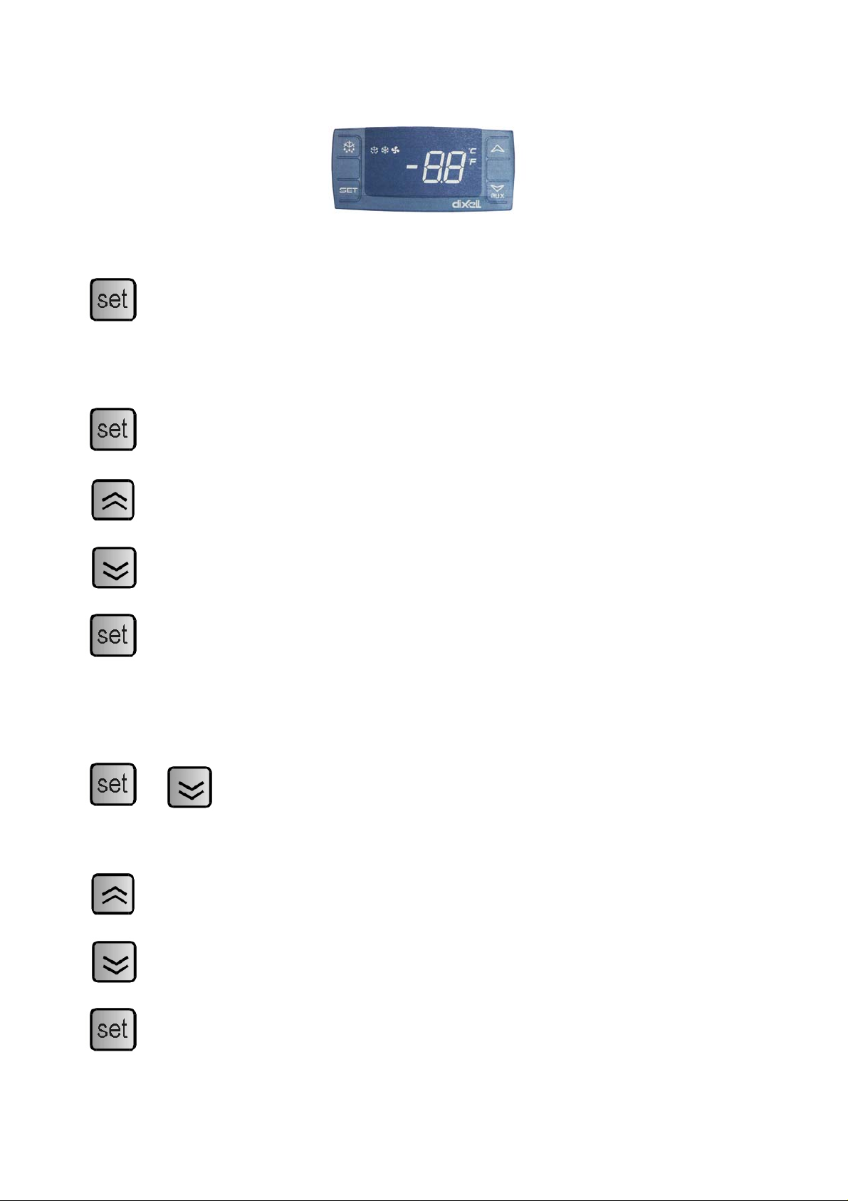
Thermostat
Display set temperature:
Press this key and the display will show the set temperature. Press the key again to return
to normal reading.
Set new temperature:
Press this key for 3 sec. and the display shows the set temperature.
Press this key to increase the set temperature.
Press this key to lower the set temperature.
Press this key to save the new settings. The display will flash with the new value and will
then return to normal reading.
Changing of parameters:
+
Press these keys continuously for 5 seconds to access the list of parameters. The display
will show the number of the parameter and after 2 seconds the value.
Press this key to increase the value.
Press this key to lower the value.
Press this key to save the new settings. The display will flash with the new value and will
then return to normal reading.
8
Page 9

See table of parameters from page 11.
larm codes:
A
1 Flashing in the display: indicates that the cabinet sensor is defective.
P
The cabinet will strive to keep the set temperature until it has been rep
A Flashing in the display: indicates that the temperature is too high.
H
aired.
A Flashing in the display: indicates that the temperature is too low.
L
D
efrosting
e recommend defrosting the freezer every three month or if the layer of ice exceeds 5 mm.
W
o never use metal or other sharp objects to scrape the internal sides as it can damage the freezer
D
1. Disconnect the freezer
2. Empty the freezer
3. Leave the freezer w
4. Use the plastic scraper to remove the
5. Remove the drain plug and open the drain on the back side of the freezer and place a tray
under the drain
6. Clean the freeze
7. Connect the freezer and it is ready for use.
ith the lid open
ice from the inner liner
r with mild detergent and wipe thoroughly
ock
L
he freezer is supplied with a lock in the handle
T
9
Page 10

Maintenance and cleaning
witch the freezer off at the socket.
S
he cabinet must be periodically cleaned. Clean the external and internal surfaces of the cabinet
T
with a light soap solution and subsequently wipe dry. Stainless steel surfaces can be maintained
using steel oil.
o NOT use cleansers containing chlorine or other harsh cleansers, as these can damage the
D
surfaces and the internal cooling system.
lean the condenser and the compressor compartment using a vacuum cleaner and a stiff brush.
C
o NOT hose the compressor compartment with water as this can cause short circuits and damage
D
on the electrical parts.
S
ervice
he cooling system is a hermetically sealed system and does not require supervision, only cleaning.
T
the cabinet fails to cool, check if the reason is a power cut.
If
you cannot locate the reason to the failure of the cabinet, please contact your supplier. Please
If
inform model and serial number of the cabinet. You can find this information on the rating label
which is placed inside the cabinet in the top right hand side.
isposal
D
isposal of the cabinet must take place in an environmentally correct way. Please note existing
D
regulation on disposal. There may be special requirements and conditions which must be observe
d.
10
Page 11

R20C (SE-45 Series)
X
AR. DESCRIPTION RANGE DEFAULT U.M.
P
Set Set point LS-US -45 °C/°F
Hy diFferential. Relay compressor tripping differential. The compressor stops on
plus reaching the Setpoint value, and restarts at temperature equal to the Setpoint
the value of the differential.
LS -55.0...HSE -45 °C/°F Lower SEt. Minimum possible setpoint value.
US Higher SEt. Maximum possible setpoint value. LSE..302 -5,0 °C/°F
Ot CAlibration 1.Calibration 1. Positive or negative temperature value added to the
value read by probe 1, based on “ot” parameter settings.
P2P Second probe presence: n=not present, y=present n/y N flag
oE CAlibration 2.Calibration 2. Positive or negative temperature value added to the -9. 9
value read by probe 2, based on “P2” parameter settings.
odS delay (at) On compressor. Delay time in activating the compressor relay after
switch-on of instrument.
AC Anti short cycle delay 0…50 5 Min
CON mpressor activation time in the event of faulty probe. On time (compressor). Co 0...99 10 min
COF OF F time (compressor). Compressor in disabled state time in the event of a faulty
probe.
CF Measurement units: °C=Celsius, °F=Fahrenheit °C/°F °C °C/°F
rES Resolution (only for °C): dE=decimal between -9.9 and 9,9; in=integer dE-in dE flag
Lod Default display: P1=thermostat probe, P2=evaporator probe, SP=Set point P1,P2,SP P1 flag
td defrost type. Type of defrosting.
El = electric defrost.
frost (hot gain = reverse cycle de s)
dtE -50…50 6 °C/°F Defrost termination temp.
idF defrost interval time. Interval between the start of two successive defrosting
operations.
MdF Max length for defrost 0…99 0 min
dFd Display during defrost: rt=real temp. it=start defrost temp., St=Set point, dF=llabel R F
Df
dAd Max display delay after defrost 0…255 1 Min
dAF Defrost delay after fast freezing 0…23 0 hours
ALc Temperature alarm configuration: rE=relative to SET, Ab=absolute rE/Ab rE Flag
ALU Higher ALarm. Maximum temperature alarm. Temperature value.
thwhich if exceeded in an upward direction triggers the activation of e alarm signal.
ALL Lower ALarm. Minimum temperature alarm. Temperature value.
of the alarm which if exceeded in a downward direction, triggers the activation
signal.
ALd 0...99 20 min Temperature alarm delay
dAO Exclusion of temperature alarm at startup. 0..23 1 hour
PbC Kind of probe Ptc/ntc Ntc flag
0 .1...25.0 2,0 °C/°F
-9.9...9.9 0 °C/°F
9...9. 0 °C/°F
0...99 2 min
0...99 10 min
EL/in In flag
0...99 0 hours
t/it/SP/d St flag
A L...99 10 °C/°F
-55...AU -1 °C/°F
11
 Loading...