

Page 1
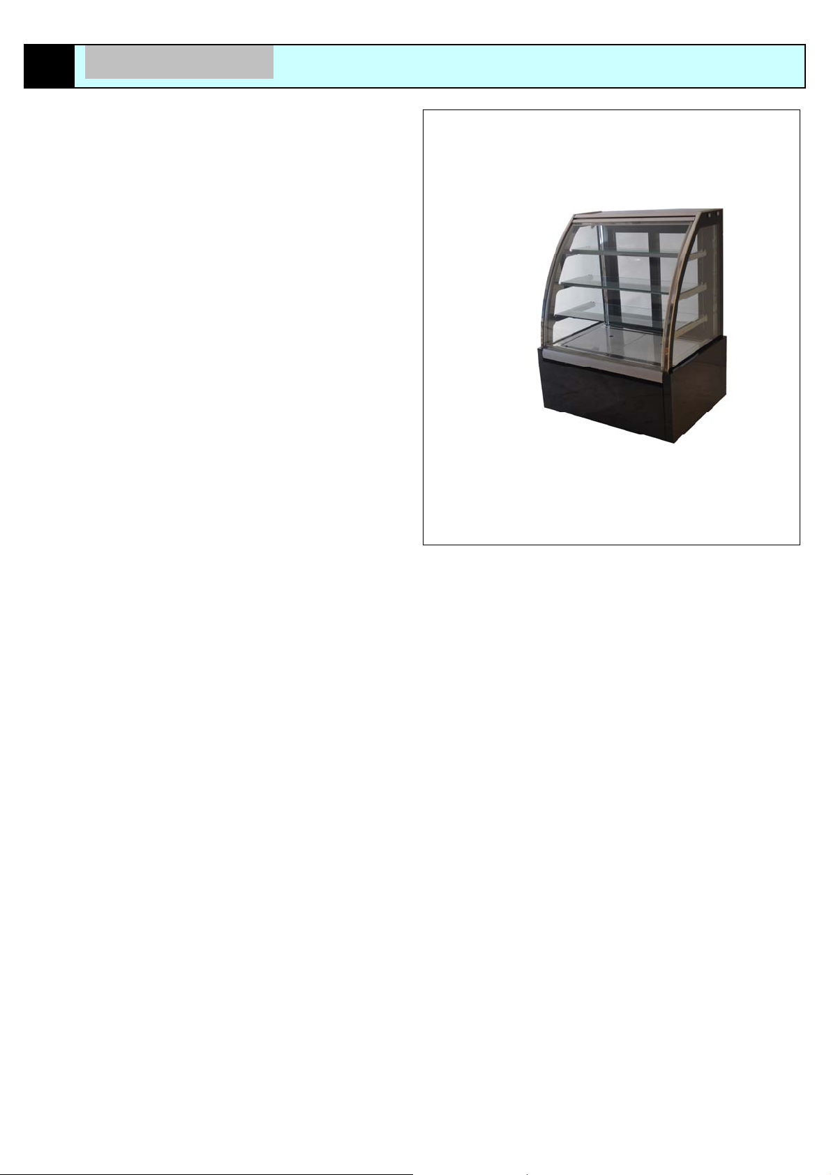
PASTRY SHOWCASE
Page 1
E
INSTRUCTION MANUAL
Page 2

LIST
1 GUIDE TO THE MANUAL Page 3
2 TECHNICAL
3 DISPLAY CASE MARKING DATA Page 5
3.1 DISPLAY CASE IDENTIFICATION Page 5
3.1.1 DISPLAY CASE NAMEPLATE Page 5
3.1.2 CE MARKING Page 5
3.1.3 NAMEPLATE OF THE MAIN COMPONENTS Page 5
4 HOW TO USE AND PRESERVE THE INSTRUCTIONS MANUAL Page 5
4.1 INTENDED USER OF THE INSTRUCTIONS MANUAL Page 5
4.2 OBJECTIVES OF THE INFORMATION IN THE MANUAL Page 5
4.3 LIMITATIONS ON USE OF THE MANUAL Page 5
4.4 HOW TO PRESERVE THE MANUAL Page 5
5 HANDLING AND INSTALLING THE DISPLAY CASE Page 6
5.1 RECEIVING THE DISPLAY CASE Page 6
5.2 UNLOADING OPERATIONS Page 6
5.3 CHECKING THE SUPPL Y Page 6
5.4 UNPACKING Page 6
5.5 PERSONNEL REQUIREMENTS Page 6
5.6 HANDING THE DISPLAY CASE Page 6
6 ENVISIONED USE Page 7
6.1 OBJECTIVE OF THE PASTRY DISPLAY CASE Page 7
6.2 AREAL NAME Page 7
6.3 USE OF THE DISPLAY CASE Page 7
6.4 SAFETY REGULATIONS DURING USE Page 7
7 TECHNICAL DESCRIPTION OF THE DISPLAY CASE Page 8
7.1 GENERAL INFORMATION Page 8
8 INSTALLATION Page 9
8.1 GENERAL INFORMATION Page 9
8.2 POSITIONING Page 9
9
9.1 GENERAL
9.1.1 INITIAL STARTUP OF THE DISPLAY CASE Page 10
9.2 POSITIONING THE TUBS Page 10
9.3 USING THE SWITCHBOARD Page 10
10 MAINTENANCE Page 1
10.1 GENERAL
10.2 CLASSIFICA
10.3 REQUIREMENTS FOR MAINTENANCE PERSONNEL Page 11
10.4 CLOTHING Page 11
10.5 CLEANING THE GLASS STRUCTURE Page 11
10.6 CLEANING THE PLASTIC AND PAINTED PARTS Page 12
10.7 CLEANING THE DISPLAY SECTION Page 12
10.8 CLEANING THE CONDENSER Page 12
11 TROUBLESHOOTING Page 13
12 DISMANTLI
12.1 GENERAL INFORMATION Page 13
12.1.1 DISMANTLING FOR DEMOLITION Page 13
12.1.2 DISMANTLING FOR TRANSFER Page 13
13 CIRCUIT Page 14
INSTRUCTIONS FOR USE Page 10
DATA Page 4
INFORMATION Page 10
INFORMATION Page 11
TION OF INTERVENTIONS Page 11
NG Page 13
1
Page 15 14 ANNOTATIONS
Page 2
Page 3
y
1
GUIDE TO THE MANUAL
This manual has been drawn up by the manufacturer and is an integral part
of the machine supply. The information it contains is for non qualified (inexpert)
and qualified personnel.
This manual defines the purpose for which the machi ne was built and it
contains all necessary information to ensure its proper installation and safe
correct operation.
Other technical information that is not included in this manual is an integr al
part of the technical file prepared by TEFCOLD A/S and is available at its
facilities.
Be sure to consult this manual before proceeding with
installation, use and an
Constant observance of the regulations it contains will guarante e perso nnel
and machine safety, low-cost operation and a longer operating lift.
The careful analysis done by TEFCOLD A/S has made it possible to
eliminate most risks. However, be sure to follow all the instructions g iven in this
manual. Always refer to the manual before carrying out any operation. Safeguard
this manual and make sure it is al ways available next to the machine or in th e
nearby vicinity.
other work on the machine.
Before conducting any type of operation, disconnect the
machine from the electrical mains.
The diagrams and drawings are furnished by way of ex amp le. I n purs u an c e
to its policy of constant development and u pdating. Th e manufacturer m ay make
any changes without giving advance notice.
This manual must be kept for the entire life of the m achine. If it is lost or
destroyed, a copy can be requested from the m anufacturer. Be sure to indicate
the data listed on the nameplate (the price will be established by the
manufacture).
TEFCOLD A/S welcomes any comments from clients concerning
improvements to be made on the machine and will assess their implementation.
This document is the exclusive prop erty of TEFCOLD A/S and cannot be
divulged to third parties, either in whole or in part, without the written
authorization of TEFCOLD A/S
TEFCOLD A/S reserves all legal rights.
All the measurements listed in this manual are expressed in mm.
Page 3
Page 4
2
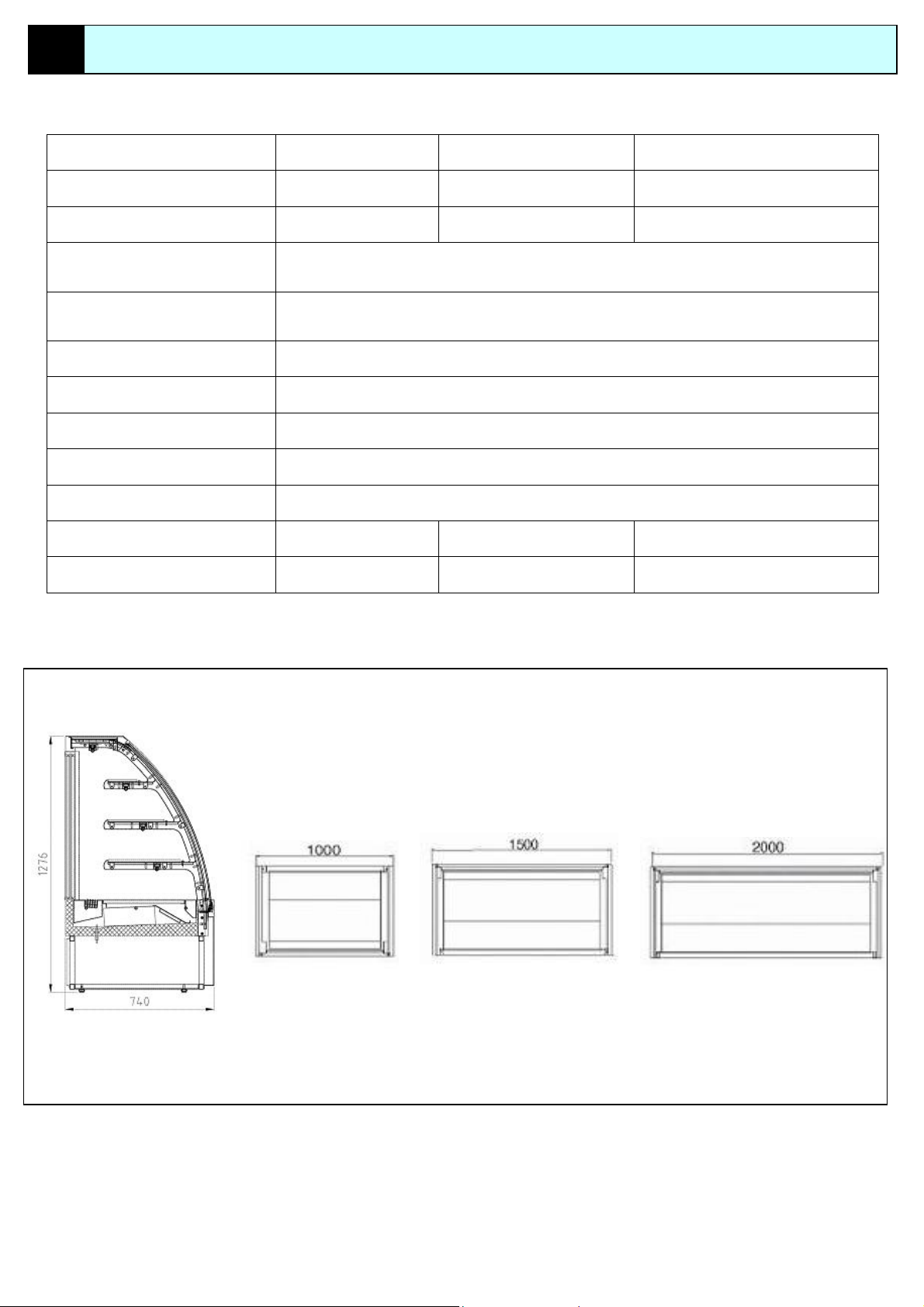
TECHNICAL DATA
MODEL
External dimensions (L*D*H) 1000*740*1276 1500*740*1276 2000*740*1276
Net Weight (Kg) 200 250 300
Interior temperature (℃) +2/+6℃
OTHELLO 100 OTHELLO 150 OTHELLO 200
Clmatic class (RH%)
Refrigerant R134a
Refrigeration Ventilate
Defrosting Stop compressor
Shelves Qty 3
Voltage 220-240V/50HZ/1PH
Input power 596 680 770
Energy consumption 9.9 11.3 12.8
30℃/60%
Dimension
OTHELLO
SECTION DRAWING
OTHELLO 100 OTHELLO 150 OTHELLO 200
Page 4
Page 5
3
DISPLAY CASE MARKING DATA
3.1 DISPLAY CASE IDENTIFICATION
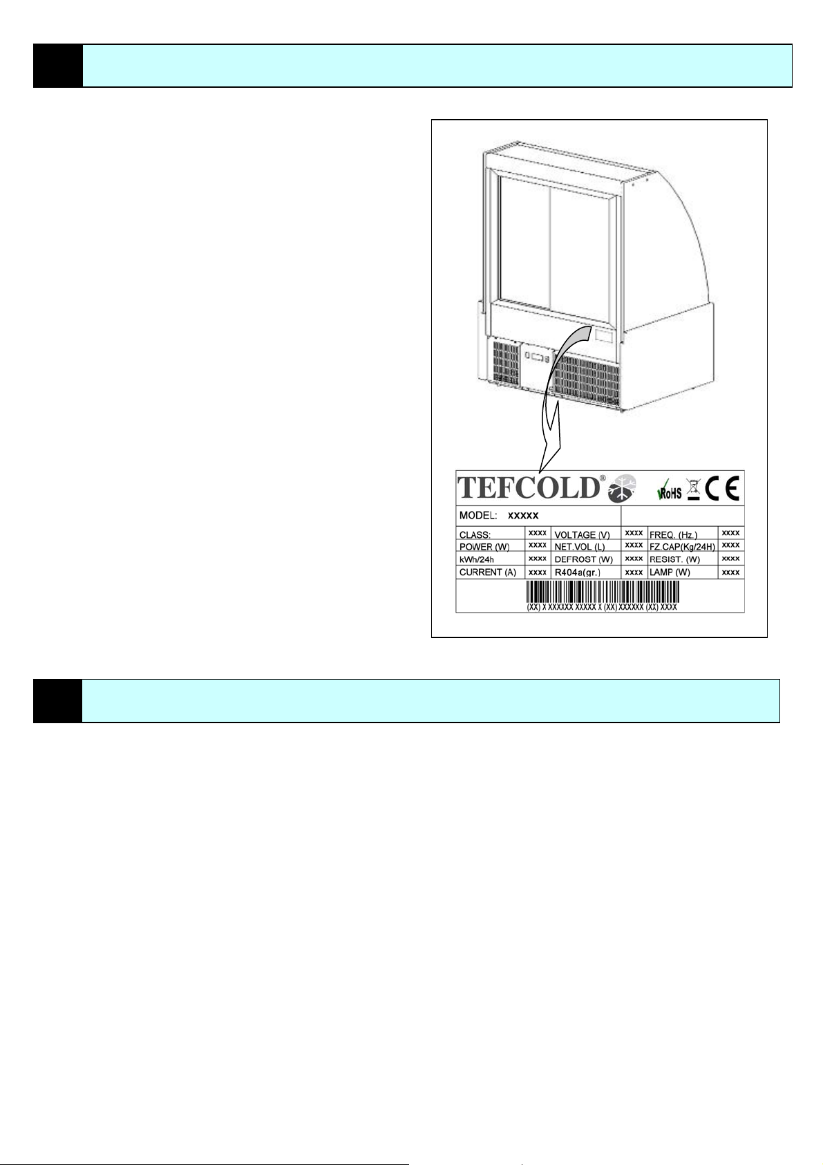
Before the display case is packaged, a nameplate is mounted on it,
identifying each case that is manufactured by its model and series.
Check to be sure that the instructions manual corres ponds to the display
case to which it is referring.
If any
information or technical assistance is required, in addition to the
model and machine type, you must also indicate its serial number etc.
3.1.1 DISPLAY CASE NAMEPLATE
The display case nameplate is locat ed on the rear part (operat or side)(Fig
1). The nameplate lists the information that identifies the machine, including
its model and serial number.
3.1.2 CE MARKING
The CE mark is applied directly to the nameplate on the display case.
3.1.3 NAMEPLATE OF THE MAIN COMPONENTS
The nameplates of all the components that w ere not manufactured direc tly
by TEFCOLD A/S (e.g. compressor, fans etc.) are mounted on the
components themselves in the position in which th ey were original placed
by the respective manufacturers.
4
HOW TO USE AND PRESERVE THE INSTRUCTIONS MANUAL
This chapter offers some indications on using the i nstruction manual and
on its use limitation.
4.1 INTENDED USER OF THE INSTRUCTIONS MANUAL
This instructions manual is intended for the following personnel.
Shipping, loading and unloading staff
Operators
Installers
Maintenance personnel
4.2 OBJECTIVES OF THE INFORMATION IN THE MANUAL
The purpose of this manual is to indicate how t he machine s hould be us ed
based on its design. It will also indicate its technical features, offering
instructions on how to move, install regulate and use it.
It will also guide you in maintenance work and facilitate spare parts orders.
Fig.1
4.3 LIMITATIONS ON USE OF THE MANUAL
It is important to remember that the instructions manual reflects the
techniques current at the time the machine was purchased, thus, the
manufacturer has the right to update the manual and the equipment without
updating the manual or any prior production, wi th the exception of unus ual
case.
4.4 HOW TO PRESERVE THE MANUAL
We would like to remind the user that the manual must be pres erved with
care to ensure it will last as lon g as the machine. Therefore, it is supplie d in
a special case that can protect it from wear and tear over years.
In addition, two copies of the section c onc erni ng “display case handing” are
furnished so that the shipper and th e personnel responsible for unloading
the machine can consult this section without referring to the main text.
If the manual gets lost or destroyed, a c opy can be requested through the
firm’s area representative or directly from the manufacturer. Be sure to
specify the type, serial number and year the display case was
manufactured.
Page 5
Page 6

5
HANDLING AND INSTALLING THE DISPLAY CASE
5.1 RECEIVING THE DISPLAY CASE
The display case has packaging around it to protect it during shipment a nd/or
storage, the body and the glass are packed separately.
Comprised of:
A wooden pallet
Two wooden boxes
Figure 2 show the standard packing.
There is a table (Fig.3) on the packing and its purpose is to give detailed
product information.
Dimensions: length width height
Hoisting hook-up points.
IMPORTANT: Remember that since cardboard packing is used, it is
subject to the action of atmospheric (rain, snow).
Therefore, the display cases must be stored in a dry indoor area.
HOIST
WITH FORK LIFT STORAGE
DIME
NSIONZ
Proc
MODEL L W H
OTHELLO 100 1035 775 1500
OTHELLO 150 1535 775 1500
OTHELLO 200 2035 775 1500
eed as follows for the unloading, transport and unpacking operations.
Page 6
Temporary or extended storage must be
done in indoor areas protected from
atmospheric agents.
Th
e display cases must be handled with
care.
Fig.3
5.2 UNLOADING OPERATIONS
The orientation of the packed display cas e mus t c omply with the indications
listed on the pictograms and the writing on the outside package.
Conduct the unloading operations using su itable hoisting equ ipment
(the capacity must be adequate for the we ight of the packed display case),
hoisting it as shown in Fig4.
5.3 CHECKING THE SUPPLY
Before taking delivery from the shipper, check the conditions of the
packi g. If it shows obvious damage on t he outside, the display case co uld
n
be damaged. In this case, unpack the display case in the shipper’s
presence. Any damage caused by i ncorrec t han dling and stora ge is not the
manufacturer’s responsibility.
CASE
IN THIS
A) Contact your area representative.
B) Draw up
C) Send a copy of the report to The manufacturer or area representative
a written report
5.4 UNPACKING
All the unpacked materials can be recycled in order to dispose of
according local legislation. Be sure to destroy plastic components to
prevent any hazards (suffocation) to children.
5.5 PERSONNEL REQUIREMENTS
We recommend that the operations to m ove the display case be handled
by personnel accustomed to using hoisting equipment, in full compliance
with the safety standards in force.
5.6 HANDING THE DISPLAY CASE
The display case can be lifted with a fork-lift truc k or with any other suit abl e
means with a minimum capacity of twice the weight of the display case
(see the specific nameplate). Operators running the hoisting equipment
must remain at an adequate distance from the hoisted part and must
ensure that no people or property is exposed t o danger if the display ca se
should drop. Movements must be slow and continu ous to prevent the case
from tipping over, etc.
The chapter offers various general information on the purposes of the
display case, describing its main functions and use limitations.
Damages caused by handling errors are not covered
by the WARRANTY
Page 7
6
ENVISIONED USE
6.1 OBJECTIVE OF THE PASTRY DISPLAY CASE
The ENERGY line of display cases has been designed to
ain the temperature of the pastry and not to lower it.
maint
T
herefore, the food can be put in the case only if it is
already cooled and has thus reached its preservation
temperature..
6.2 AREAL NAME
No other special technical knowledge is required to use the
cases.
display
Attentive reading of this manual is sufficient.
6.3 USE OF THE DISPLAY CASE
The room or area in which the display case is to be installed
must have the
--Indoors
following characteristics:
RIGH
T SIDE
CUS
--Minimum temperature of -18℃
--Maximum temperature of +30℃
--Relativ
6.4 SAFETY
To ensure accident prevention, y
the follo
and turn
The latter operation must be carried out exclusively by
authorized personnel trained on how to use the display case.
When this manual discusses switches and other components,
it indicates if they are to the right or left of the display case.
In most situation, the terms “left” and “right” refer to the
position of the operator standing in front of the work surface
and facing forward
e humidity (RH) +60%
PRECAUTIONS DURING USE
ou must read and observe
wing precautions before installing the display case
ing it on.
--Never allow anyone to use the display cause without proper
instruction.
--Careful
case.
--F
--Make sure that each
installed correctly.
ly read the instructions manual before using the display
ailure to observe use regulations can cause accidents
TOMER SIDE
piece of equipment or accessory is
OPERATOR SIDE
LEFT SID
Fig.5
E
Page 7
Page 8

7
TECHNICAL DESCRIPTION OF THE DISPLAY CASE
7.1 GENERAL INFORMATION
This chapter offers a technical description of the display case and its
operation. It supplies all the inf orma tion deemed useful for the operator an d
maintenance personnel so they can gai n a better understanding of correc t
operation to enable more rapid identification of any fault or malfunctions.
Display section
The display section is the area in the display case that holds
the bubs of food. The model and name for the display case is
different, but their function is same.
Glass stru
The glass structure is composed of two glass side panels
and a front window that makes it possible to
--guar
--protect the contents of the display section from foreign
matter
All the glass can be dismounted simply by removing the
screws and the connection bar. We recommend performing
these operations with the maximum care, observing the
indication listed in the maintenance chapter.
.
Motor compartment
The motor compartment is located in the lower section of the
showcase and all the components required for machine
operation are positioned together in a unit referred to the
condenser unit.
--The main components of the condenser unit are:
--Compressor
--Condenser
--Fan
--Condensation evaporation tub
--Solenoid valve
--Filter
--Other refrigeration components
The muter compartment is protected by a iron bracket.
Compressor split and rear grate that are bolted on to ensure
maximum safety. In particular during normal operation no one
is able to access it an come into contact with live or moving
elements .Only qualified technicians are allowed to access it.
Observing safety and maintenance regulations..
cture
antee the food clean
.
Page 8
Control panel
The control panel is the element th at manages the operation of the display
case.
This management (temperature control and maintenance, defrosting) is
entrusted to a command switchboa rd. In any event, the operator can utilize
this component to change the temperature inside the display section.
Verify that when the display case is installed, the general switch is it.
When the main switch is on, this guarante es the operation of the oil-heating
resistor inside the compressor (this is independent of the start-up of the
display case).
2
1
3
1. THERMOSTAT
2. MAIN SWITCH
3. LIGHT SWITCH
Fig.6
Page 9

r
8
INSTALLATION
8.1 GENERAL INFORMATION
This chapter offers all the technical information needed for installment
operations, in accordance with the regulations in force. The ins tallation a nd
test of proper display case operation must be carried out by qualified
personnel in full respect of the regulations in force and of the attached
assembly instructions. In the event of installat ions that do not comply with
the recommended installation, TEFCOLD A/S declines any responsibility
for personal injuries and/or property damage.
8.2 POSITIONING
The position of the display case is a very important factor that can
compromise proper machine operation. Correct pos itioning influences the
life of the display case and its c omponents. Above all, however, it affects
system operating expenses.
We advise you to carefully follow the instructions below (Fig.7 8 ).
Our technical servicing office can give you any additional clarificatio ns that
may be needed.
NEVER PERFORM
ANY OPERATIONS THAT ARE NOT CLEAR
Using a water level, verify that th
If necessary, use wooden shims to compensate for any defects in the
flooring.
e display case is perfectly flat.
Fig.7
NEVER place the display case near:
Doors
Windows
Sources of heat (e.g. radiators, heaters, etc.)
1) Do not place the power cable in a transit area. We also recomme nd
protecting the cable with trucking anchored to the floor.
2) NEVER touch the power plug if your hands are wet.
3) Verify that the power mains network is earthed in accordance with
the regulations in force.
4) NEVER insert any adapters or multiple o n the supply plug used to
connect the display case.
5) NEVER use extensions to connect the display case to the mains.
6) Verify that the mains voltage complies with the data listed on the
nameplate of the machine (maximum allowable variation ±6%.
TEFCOLD A/S declines any responsibility for personal injuries o
property damage caused by incorrect installation.
Fig.8
Page 9
Page 10

9
INSTRUCTIONS FOR USE
9.1 GENERAL INFORMATION The control switchboard is supplie d with a standard setting es tablished by
This chapter offers instructions for correct use ice cream display case.
9.1.1 INITIAL STARTUP OF THE DISPLAY CASE
Before starting up the display case, make sure there are no remaining
piec
es of the packaging inside the display section and then clean the
display case thoroughly.
9.2 POSITIONING THE TUBS
Placement of the tubs inside the display sec tion is an easy operat ion tha t is
also very important for the operation of the display case and proper ice
cream conservation. There is a sticker inside the d isplay section indicating
the loading limit of the display case. This reference allows you to get
maximum performance from the display case and optimum product
conservation.
er superpose the ice cream tubs.
Nev
IMPORTANT: NEVER exceed the loading limits; this will damage both the
product and the display case.
9.3 USING THE SWITHBOARD
The control panel contains all the instruments that make it possible to
manage the display case, as indicated in (Fig .9).
the manufacturer. However, the operator can intervene on the switchboard
to vary the temperature inside the display sec tion and to per form additio nal
defrosting.
in display panel
1)ma
press down “SET” buzzer, the display panel will allow 10 sec onds
After
operating time.
2)Digit
al display
h:procedure setting mode or main control panel setting mode
DP1 flas
Fig.9
Page 10
Page 11

10
MAINTENANCE
10.1 GENERAL INFORMATION 10.4 CLOTHING
This chapter offers all the technical information required to conduct regular
and extraordinary maintenance in compliance with the regulations in force.
BEFORE STARTING ANY MAINTENANCE WORK OR OPERATOR
CHECKS, YOU MUST :
Verify that the display case is turned off and that it is disconnected
from the power mains. Lis
Set up a sign indicating the work that is being done.
If necessary, procure adequate lifting equipment. IMPORTANT TOOLS FOR MAINTENANCE PERSONNEL
Verify that the operations to be done will not injure personnel or
damage nearby machinery.
display case has not been used for a long time (winter season), we
If the
are commend the following procedures before turning it on again.
Thoroughly clean the display section
Thoroughly clean the condenser
Thoroughly clean the glass structure
Thoroughly clean the external structure
Check the Ventilator fans to be sure they are not clogged.
IMPORTANT: Incorrect or poor maintenance can make the display case
hazardous to the operator and the personnel working near it.
10.2 CLASSIFICATION OF INTERVENTIONS
Maintenance work falls into two categories:
Normal maintenance: defined as work done to maintain normal
operating conditions for the display case, i.e. without requiring the
replacement of any parts.
This includes:
ntenance during the first ten hours of operation.
- Mai
eekly maintenance work.
- W
- Mont
- Work done every six months.
- Work done annually.
Extraordinary maintenance; defined as work comprising:
- W
- Work to be done at long intervals, i.e. work corresponding to the e nd
A
TTENTION
All the operations preceded by the symbol ” “ must be performed by a
specialized technician.
hly maintenance work.
ork required due to malfunction;
of the work of a main part and requiring the interru ption of display
case operation.
10.3 REQUIREMENTS FOR MAINTENANCE PERSONNEL
Maintenance of these machines must be c onducted SOLELY by qualified
personnel specializing in working with refrigerating systems.
The must know and understand the written instructions, laws and
regulations.
The instructions drawn up by TEFCOLD A/S include the man ual and the
signs on the machine and control parts. The laws and regulations i n force
in the country where the machine is bein g used may entail greater safety
provisions or identify further risks with respect to the ones listed in the
manual.
They must have had actua l training on the operations to be performed.
Maintenance workers must have re ad the instructions in this manual and
be familiar with all the commands s o that they can work in full co mpliance
of the safety regulations currently in force.
They must not be drug or alcohol abusers.
The use of these substances impairs ready reflexes and coordination.
A technician who uses prescription drugs must obtain medical advice on his
ability to conduct certain types of activities.
Page 11
Before starting any work operation, maintenance workers mist wear
suitable clothing that respects the indications envisioned by current
regulations. All the instruments that are used must be in perfec t condition
and be type tested. The maintenance worker must ALWAYS check the
supplied devices and replace them if they are damaged or are not
compliant.
ted below is a table with the devices the TEFCOLD A/S recommends.
WEAR PROTECTIVE GLOVES
WEAR GOGGLES (DURING WELDING WORK)
WEAR SAFETY
WEAR WORK OVERALLS WITHOUT ANY
LOOSE ENDS
SHOES
10.5 CLEANING THE GLASS STRUCTURE
Maintenance of the glass structure is very simple but i t must also be done
c
arefully due to the type of elements it comprises. It must be cleaned
weekly using warm water and Marseilles soap.
NEVER use inf
NEVER spray water to clean the display case.
o clean the display section, you ne e d to remove all the ice cream tubs and
T
place them in the refrigerator.
lammable or abrasive products.
Page 12
10
MAINTENANCE
10.6 CLEANING THE PLASTIC AND PAINTED PARTS
Learn these parts with warm water and neutral Mars eilles soap. Dry well
with a soft cloth (the display case must be turned off and disconnected from
the power mains).
A
TTENTION
NEVER use inf
NEVER spray water to clean the display case
10.7 CLEANING THE DISPLAY SECTION
To clean the display section, you need to remove all the cake and place
them in the refrigerator. At this point, you can clean this section.
Use only warm water and neutral Marseilles soap. Dry well with a soft c loth
(the display case must be turned off and disconnected from the power
mains).
TTENTION
A
NEVER use inf
NEVER spray water to clean the display case
lammable or abrasive products.
lammable or abrasive products.
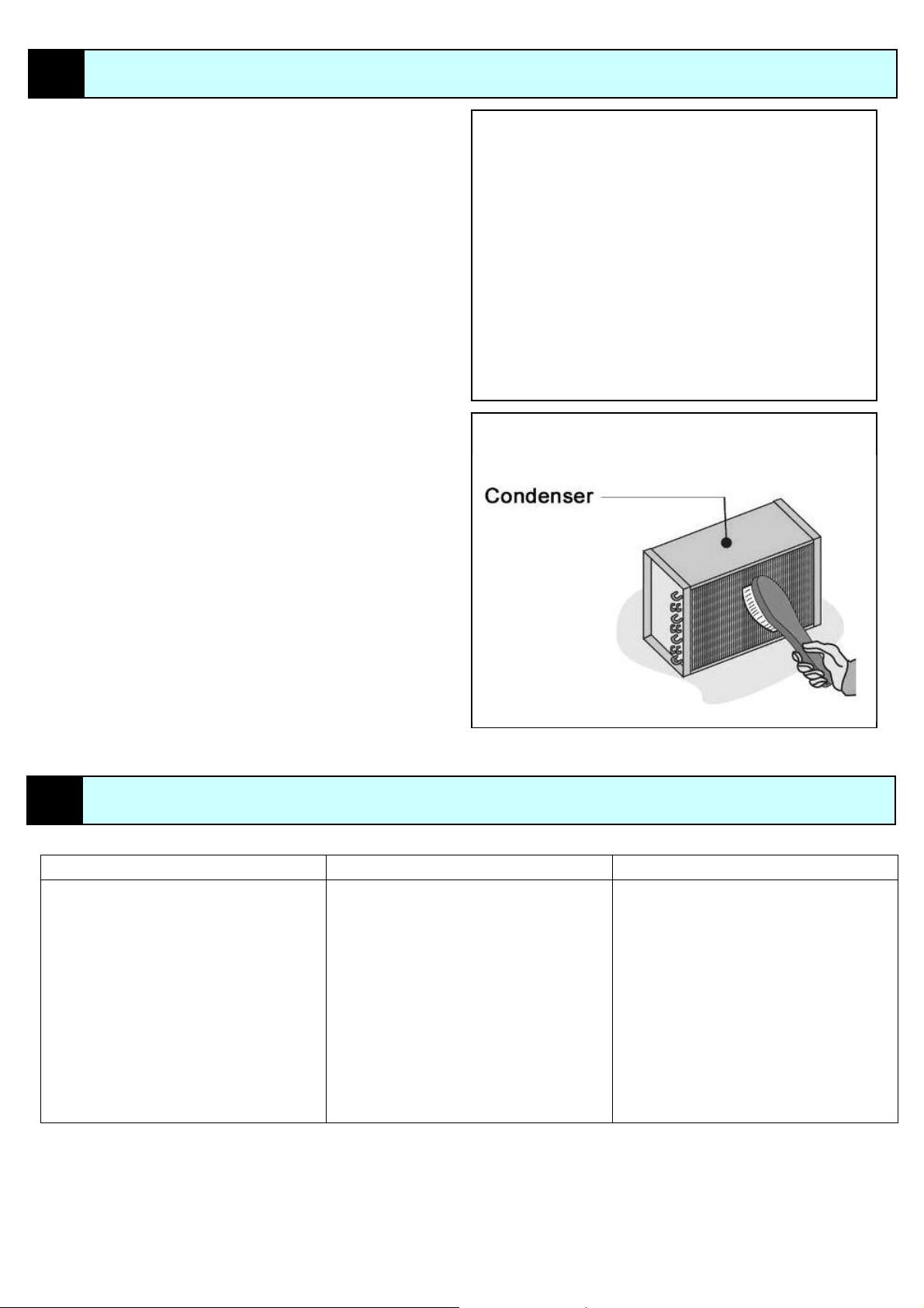
10.8 CLEANING THE CONDENSER
Maintenance work falls into two categories:
The condenser must be cleaned every 30 days max imum and this inv olves
removing the dust that collects in the fins.
IMPORTANT: Disconnect the display case from the power mains and
follow the instructions listed in the “General Information” section of this
chapter.
ing must be done gently without bendi ng or bre aking t he fi ns, us in g a
Clean
stiff brush.
IMPORTANT: Do not use fluids to clean the condenser.
T
o access the condenser, remove the front grate (Fig.10), removing the
screws that fasten it to the structure.
11
TROUBLE SHOOTING
No supply voltage. No supply voltage. Check the supply cable.
Main switch OFF. Main switch OFF. Verify that the main switch is section ON.
Plug not connected. Plug not connected. Check the position of the plug.
Switc
hboard not set correctly. Switchboard not set correctly. Set proper temperature.
Product exceeds loading limits. Product exceeds loading limits. Remove excess product.
Product put in when too hot or moist. Product put in when too hot or moist. Check product.
Electrical system fault. Electrical system fault. (*)Contact a qualified technician or TEFCOLD A/S.
(*)Contact a qualified technician or TEFCOLD A/S.
Refrigerating system fault. Refrigerating system fault.
Use
Floor uns
Sc
table. Floor unstable. Remove any external objects in contact with the
t with external objects. Contact with external objects.
rews loose (e.g. glass structure of grids).
Important
If these solutions are not successful, please contact TEFCOL D A/S’s Technical Servicing Department.
The operator must never intervene if intervention by qualified personnel is specified (*)
FAULT CAUSE SOLUTIONS
shims to stabilize the display case.
display case. Contac
Screws loose (e.g. glass structure of grids).
Chec
k screw tightness.
Fig.10
Page 12
Page 13

12
DISMANTLING
12.1 GENERAL INFORMATION 12.1.2 DISMANTLING FOR TRANSFER
This chapter offers all the technical informatio n required to dismantle the
display case in compliance with the regulations currently in force.
12.1.1 DISMANTLING FOR DEMOLITION
All of
If th
e display case is going to be scrapped, this creates two separate
problems:
Dis
The first one is administrative: The competent public offices must be
notified that the machine is being s crapped so that the document ation they
have on file about the machine can be canceled.
Perfec
display case comes with a set of legal documents, such as the manual,
The
the nameplate and the various authorizations that must be examined once
the decision is made to demolish the machine.
The second one involves physically display of the display case; to do
this, it is essential to contact specialized disposal companies or the
manufacturer.
eeding with demolition of the display case is absolutely forbidden
Proc
unless these indications have been observed.
If the display case needs to be dis mounted in order to move it to an other
area, proceed as follows:
Before s
tarting to disassemble the machine, you are required to shut off the
electrical supply.
this must be done by setting up special sig ns to i ndic ate what you ar e
doing.
assembly must be carried out by quali fied personnel or directly by the
manufacturer, being sure to separate and identify (mark) all the
components.
t organization during disassembly guarantees perfect and safe
reassembly.
e material must be kept in a dry area that is protected against weather.
All th
remounting the machine, check the material thoroughly for any
Before
damage.
Page 13
Page 14

13
OASI CIRCUIT CAPTION
CIRCUIT
Page 14
Page 15

14
ANNOTATIONS
Copy to be sent to the manufacturer – TEFCOLD A/S
CLIENT: TEL:
A
DDRESS: ZIP CODE:
C
ITY: PROVINCE:
Retailer’s stamps:
Delivery date:
Display case model:
Following installation of the display case, the client hereby declares that the work was carried out correctly and in compliance with the present i nstructions
manual. He further declares that he has seen its perfect operation and is aware of the instr uctions for correc t use and proper operation and m aintenance of the
display case.
CLIENT signature:
CORRECT INSTALLATION FORM
Installer’s stamps:
First name:
Last n
ame:
Address:
C
ity: Tel:
Delivery document:
S
erial number: Year:
Signature of the RETAILER/ INSTALLER:
*This declaration is not valid unless filled out completely and signed.
Zip code:
Page 15
Page 16

Since TEFC
OLD A/S is constantly working on the improvement the production, models, shapes, materials and colors
shown in this manual, could be modified as notice.
Page 16
 Loading...