


VERSION 1.2

Warnings
Warranty & FCC
Warnings & Important Notes
Before connecting this unit to other devices, turn o
the power to all units. This will help prevent malfunctions and/or damage to speakers or other
devices. If you need to connect/disconnect wires during use, ALWAYS make sure to connect the cable
to the OP-1 first. Never connect the 3.5mm plugs going from the OP-1‘s mic input or line output to a
mic input on a sound card with phantom power active. This could destroy the ports on the OP-1. Be
sure to charge the unit using only 5V USB power, such as that from the USB ports of a computer, or by
using a dedicated USB charger. Make sure you always have the OP-1 placed so it is level and sure to
remain stable. Never install or use the unit in any of the following locations:
•Humid environments or baths and washrooms.
•Safety-critical applications.
•Nuclear facilities and weapons systems.
•Aerospace applications or environments for automotive installations.
Store small parts out of the reach of children and
infants. If accidentally swallowed, contact a doctor immediately.
Warranty and return policy
The OP-1 is fully factory tested and comes with a 12 month (from purchase date) warranty. This does not
include malfunction due to misuse of the device, such as being dropped, crushed or used in an
application of inappropriate voltages to the device’s connectors or improperly designed or executed
modifications. In particular, you are the sole responsible for damage caused by a charging
method other than 5V USB power. The general warranty policy does not cover ESD (static discharge)
damaged products due to improper handling.
The warranty does not cover shipping charges.
Make sure to read the Terms & Conditions here: http://teenageengineering.com/terms-and-conditions
FCC ID: Z23TE2A1
IC: 9915A-TE2A1
This device complies with Part 15 of the FCC Rules. Operation is subject to the following two conditions:
(1) this device may not cause harmful interference, and (2) this device must accept any interference
received, including interference that may cause undesired operation.
This device complies with Industry Canada licence-
exempt RSS standard(s). Operation is subject to the following two conditions: (1) this device may not
cause interference, and (2) this device must accept any interference, including interference that may
cause undesired operation of the device.
FCC NOTE:
This equipment has been tested and found to comply
with the limits for a Class B digital device, pursuant to Part 15 of the FCC Rules. These limits are designed to
provide reasonable protection against harmful interference in a residential installation. This
equipment generates, uses and can radiate radio frequency energy and, if not installed and used in
accordance with the instructions, may cause harmful interference to radio communications. However,
there is no guarantee that interference will not occur in a particular installation. If this equipment does
cause harmful interference to radio or television reception, which can be determined by turning the
equipment o and on, the user is encouraged to try to correct the interference by one or more of the
following measures:
•Reorient or relocate the receiving antenna
•Increase the separation between the equipment and receiver.
•Connect the equipment into an outlet on a circuit di erent from that to which the receiver is connected.
•Consult the dealer or an experienced radio/TV technician for help.
The manufacturer is not responsible for any radio or
TV interference caused by unauthorized modifications to this equipment. Such modifications could void the
user's authority to operate the equipment.

OP-1 Operator’s Manual
Benutzerhandbuch
Mode d’Emploi
©2010-2012 Teenage Engineering. All rights reserved.
Table of Contents
1 Hardware - Overview
1.1Power On/O
1.2Charging the Battery
1.3Inand Outputs
1.4OP-1 Side View
2 Layout
2.1Keys and Knobs
2.2LEDs
3 Musical Keyboard
3.1Playing a Sound
3.2Octave Shift
4 Main Modes
4.1The Four Main Modes
4.2Using SHIFT + Any Main Mode
4.3Main Mode Screen Examples
5 Synthesizer Mode
5.1Synthesizer Mode - Introduction
5.2Synthesizer Engines
5.3Envelope
5.4Play Mode
5.5Synthesizer E ect
5.6Synthesizer LFO
5.7Change Sound
5.8Saving a Sound
5.9Sound File Structure
6 Drum Mode
6.1Drum Mode - Introduction
6.2DRUM Sampler Engine
6.3Laying Out A Drum Kit
6.4Dynamic Envelope
6.5Importing Your Own Sounds
6.6Using OP-1’s Standard Layout
6.6DBOX Drum Engine
TOC
7 Sequencers
7.1Sequencers - Introduction
7.2Selecting a Sequencer Type
7.3ENDLESS Sequencer
7.4ENDLESS Functionality
7.5PATTERN Sequencer
7.6PATTERN Functionality
7.7TOMBOLA Sequencer
7.8TOMBOLA Functionality
7.9FINGER Sequencer
7.10FINGER Functionality
8 Tape Mode
8.1Tape Mode - Introduction
8.2Record To Tape
8.3Overdubbing
8.4Rewind And Fast Forward
8.5Jump To the Start of Tape
8.6Jump To the End of Tape
8.7Reverse Playback
8.8Recording Level
8.9Tape Editing
8.10Advanced LIFT
8.11Changing Tape Speed
8.12Advanced Recording Techniques
8.13Tape Tricks
8.14Erasing Tape
8.15Backing Up Your Tape
8.16Bars
9 The Mixer
9.1Mixer - Introduction
9.2Sound Path
9.3Mixer
9.4EQ
9.5Master E ect
9.6Master Out
10 Tempo
10.1Tempo - Introduction
10.2Setting the Tempo/Tap Tempo
10.3Using the Metronome
10.4Free Mode
10.5Beat Match
10.6Sync Mode

TOC
(Continued)
11 |
Help |
16 |
Exercises |
11.1 |
The Help Button |
16.1 |
Recreating Sounds |
11.2 |
Tools |
16.2 |
Starting Out |
11.3 |
Battery Level |
16.3 |
Helicopter Sound |
|
|
16.4 |
Singing Birds Sound |
12 |
Recording External Sources |
|
|
12.1 |
Using the Mic/Input Key |
17 |
Reference |
12.2 |
Mic/Input Key in Synth Mode |
17.1 |
Synth Engines |
12.3 |
Mic/Input Key in Tape Mode |
17.2 |
E ects Reference |
12.4Sampling Using The Built in Microphone
12.5 Creating a Drum Kit From FM Radio Waves |
18 |
Hardware |
13 Song Rendering and Connectivity
13.1Album
13.2COM
13.3OP-1 Mode
13.4CTRL (Controller) Mode
13.5DISK Mode
13.6OPT (Option) Mode
13.7Sequencing External Equipment
13.8Controlling Ableton Live
13.81Mac OS X Install
13.82Windows Install
13.83Finalize
13.84Ableton Live Key Assignments
13.9Controlling Propellerhead Reason
14 SHIFT Key
14.1SHIFT Key
14.2Change a Single Module
14.3SHIFT + Main Mode Keys
14.4SHIFT + Arrow Keys
14.5SHIFT + Encoders
15 LFO Reference
15.1Element LFO Mode
15.2Random LFO Mode
15.3Tremolo LFO Mode
15.4Value LFO Mode
15.5The MIDI LFO Mode
15.6Crank LFO Mode
15.7Bend LFO Mode
15.8Additional Symbols Used in LFO Mode
Introduction
Dear user, |
Quick Guide Overlay |
Thank you for choosing the OP-1 musical instrument.
This device is precision made to last many years and designed to be practical, intuitive and to give you
hours of creative pleasure. To get the most out of your new OP-1, be sure to read this operator’s
manual carefully. For even deeper understanding and the latest pro tips, please visit the OP-1 community
website http://ohpeewon.com
- Teenage Engineering
About this manual
This manual is written more or less with one chapter for every key you find on your OP-1 (except the
musical keyboard which counts as one).
You create sounds (using the Synthesizer or Drum
Mode keys) that you may also Sequence before you record to TAPE and finally MIX. You also have the
option to record a final mix to ALBUM.
To make things easier, all keys, encoders and important modes relevant to the current page are
marked on the OP-1 illustration in the page header.
Although the OP-1 is designed to be very intuitive, reading this manual will give you a deeper
understanding of the concept behind many of OP-1’s functions and modes. Anyway, don’t be afraid of
playing around and exploring. You can always come back to this manual at a later stage.
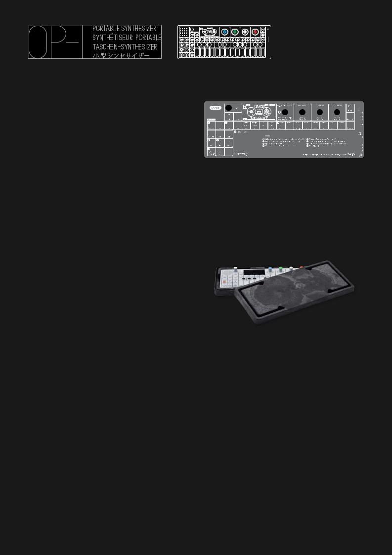
What’s in the Box?
Check that the following items are included when
you open the box: OP-1 Unit, USB Cable, Quick Guide Overlay and a Set of rubber bands.
The OP-1 comes with a transparent overlay for quick reference of the keyboard layout. Keep this for future
reference.
Rubber bands
You may use the PaperFoam box in which your OP-1 came delivered as a temporary storage box. Use the
rubber bands to seal the box.
USB Cable
The OP-1 uses a standard USB to mini USB cable for
charging the OP-1 and for transferring data between your OP-1 and your computer.
If you want to use an external power adapter instead
of a computer for charging the battery, make sure you are using a 5V USB standard charger. A
dedicated charger works more e ciently and will charge the battery faster.
Quick Guide
Power on
Make sure that your OP-1 is fully charged. If not,
insert the USB cable into the USB port located on the right side of your OP-1 and connect it to a computer
or to a USB power adapter.
Turn on your OP-1 by sliding the white power switch located next to the USB port towards you. The
Teenage Engineering symbol will be displayed briefly on screen. Turn up the volume using the white knob
located on the left side of the screen (clockwise increases volume). You are now ready to play your
new instrument.
Playing a synthesizer sound
Press the Synthesizer key. Select a synthesizer sound by pressing any
key from 1-8. (These keys 1-8 are called Sound selection keys in this
manual). Press any key on the Musical Keyboard.
Playing a drum sound
Press the Drum key. Select a drum sound by pressing any Sound
selection key from 1-8. Press any key on the Musical Keyboard.
Recording to tape
Press the TAPE key.
Select TRACK by pressing any of the 1-4 keys located under the
screen. (These keys are called T1T4 in this manual). Press REC +
PLAY to start rolling tape.
Play the Musical Keyboard. Use the STOP key to stop recording. Rewind to the starting point by pressing
and holding the REWIND key. Now press PLAY to listen to your recording.
Using the mixer
First make sure that you have some recorded material on the
tape.
Press the MIXER key to open up the Mixer view. Now press the
PLAY key to start playing the tape.
Depending on which track that contains recorded material, the corresponding VU meter will indicate
the sound level.
Adjust the individual track level by turning the color related knob.
Hold down the SHIFT key while turning the color
related knob to adjust the PAN for each track.
Congratulations! You have learned the basic fundamentals of your OP-1. To understand all of your
OP-1’s functions, please read this operator’s manual carefully.
A good way to start is to follow the Quick guide printed on the plastic overlay that comes with your
OP-1.

1 Hardware - Overview
1.1 Power On/O
To power on your OP-1, slide the white power switch located on the right side of the device towards you. The display will light up and the OP-1 loads necessary system data.
To power o , slide the power switch away from you. Data is always stored on-the-fly, so you don’t have to worry about saving your sound or recordings.
Everything will still be there the next time you power on your OP-1 exactly the same as when you left it.
NOTE: The more samples or other data you store on your OP-1, the longer the start-up process will be. It’s a good habit both for start-up time and for safety to back-up and clear your OP-1 occasionally.
1.2 Charging the Battery
The first thing you should do is to connect your OP-1 to a computer (or optional charger) via the USB port located on the right side of the unit. Make sure to keep your OP-1 connected until you have fully charged the internal battery. This will be indicated by the same LEDs used for the VU meter.
To check the battery level, press the Help key. The LEDs will light up to indicate the level. Five lit LEDs is equal to a fully charged battery.
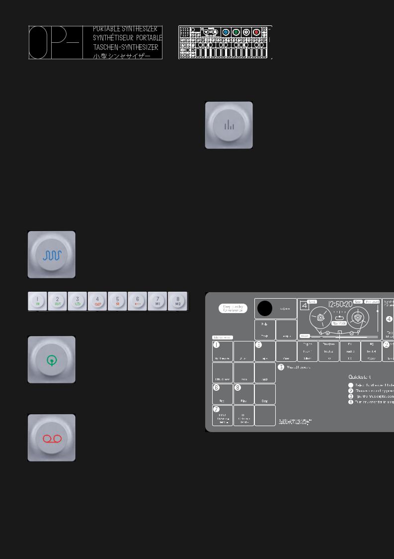
1.3 In and Outputs
OP-1 has three ports located on the right hand side of the unit.
•Audio in/Line in
•Audio out for headphones/line out
•USB port for charging, transferring files and MIDI
1
Hardware Overview
NOTE: To adjust the input level press SHIFT + Mic key. To adjust the output level, turn the volume knob
or set the master L/R level output located in mixer T4.
1.4 OP-1 Side view
For strap
3.5 mm
Audio Out / Headphones
3.5 mm Audio In
USB for Charging the battery, for transferring files and for MIDI
Off
Power switch
On
For strap
If you turn your OP-1 upside down, you will find symbols and braille text that indicates I/O location.

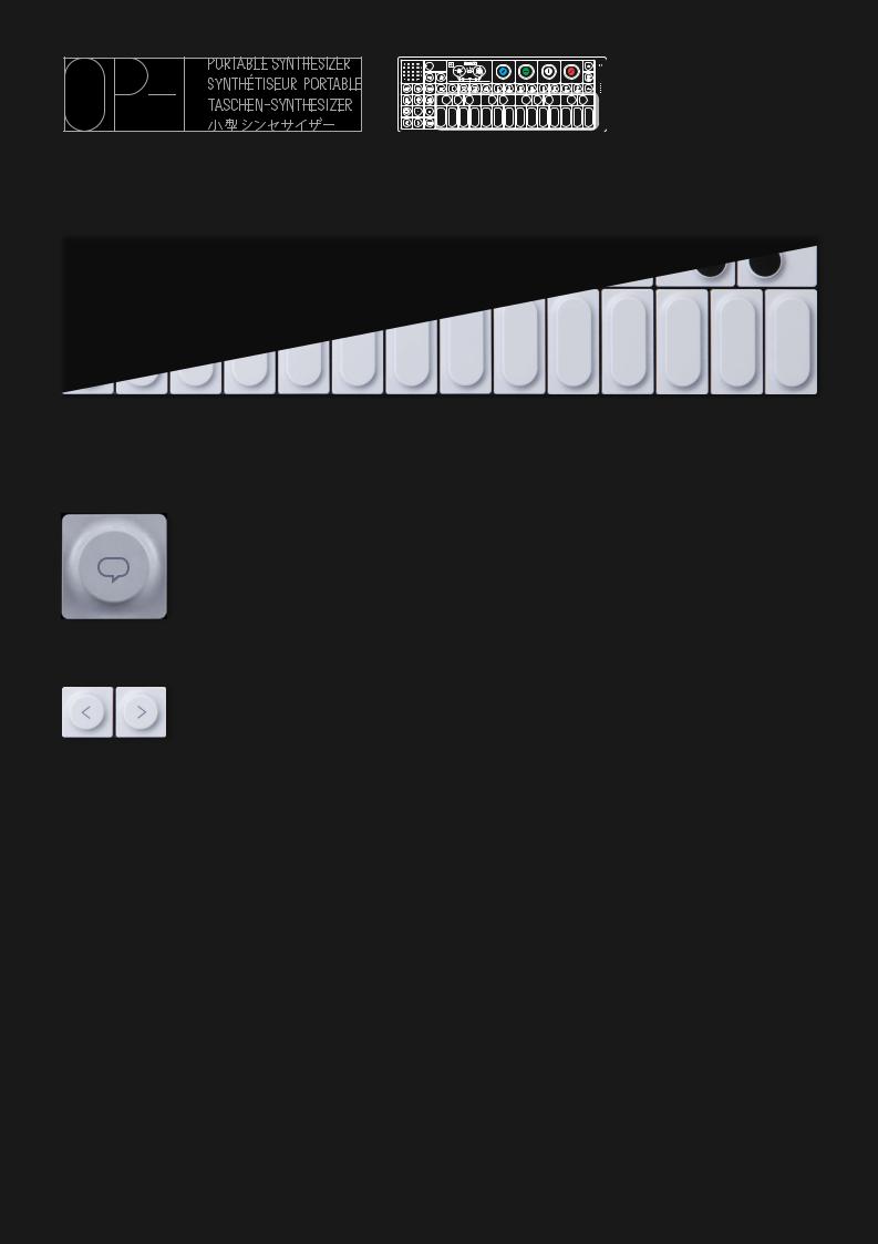
2 Layout
2.1 Keys & knobs
The layout of the OP-1 is divided into di erent groups
for easy reading and intuitive workflow.
Turn the Volume knob to set the master volume.
Speaker |
Volume |
Display |
Main Modes |
Help Tempo |
T1 - T4
Tape edits
Tape
Transport
Rewind / Forward |
Shift |
Octave shift +/- |
|
Step Forward / Back |
|
2
Layout
The four color encoders are related to the graphical interface on the display. A green graphical element or text hints that the green encoder will change its value or position.
Color Coded Encoders
Mic / Input
Sound 1 - 8 / Tape tricks |
Album / Com |
Sequencer
Musical Keyboard
2.2 LEDs
On the right side of your OP-1 you find the built in Microphone and VU/Battery LEDs
Built in |
VU/Battery |
Microphone |
indicator |
3
Musical Keyboard
3 Musical Keyboard
3.1 Playing a Sound
Press any key on the musical keyboard and you
should instantly hear a sound. If it is silent, turn up the master volume located next to the speaker,
or press the Synthesizer or Drum key.
PRO-TIP: Press and hold HELP while playing the musical keyboard
to let your OP-1 display the current note.
3.2 Octave shift
Use the Arrow keys to transpose
octave while in Synthesizer or Drum mode.
NOTE: Before you start creating your first masterpiece, read this manual carefully to avoid
deleting or over-recording your work.

4 Main Modes
4.1 The Four Main Modes
Your OP-1 is designed to be easy to use, so the most important functions are located on the first keys to the left on the upper row. The four keys are grouped together and are called Main Modes.
The four main modes are: Synthesizer, Drum, Tape and Mixer. Each key has a dedicated symbol and color to make it easy to navigate through the di erent screens and to find the appropriate key related to the currently active mode.
Example: All keys with orange symbols are related to the Tape because the tape symbol is orange.
4.2 Using SHIFT + any Main mode key
By pressing SHIFT + a Mode key you invoke special settings or functions for that mode. For Synthesizer and Drum you undo edits and tweaks that you made to the sound. For SHIFT + Tape you enter the Tape erase function.
SHIFT + Mixer takes you to the Signal Flow screen
4
Main Modes
4.3 Main Modes Screen examples
Synthesizer using String Engine.
Drum using a sample
Tape
Mixer
5 Synthesizer Mode
5.1 Synthesizer Mode – Introduction
OP-1 has several original synthesizer engines. Each one has its own personality. When in Synthesizer Mode, the synthesizer engine’s visual is always located under T1 and is also the first screen that will show up when you change or select a sound.
Each sound is built up from four modules located under the T1, T2, T3 and T4 keys, lined up under the display:
NOTE: The T1-T4 are soft keys, which means that in Synthesizer and Drum mode they function as described here. In Tape mode they are track keys T1-T4 and in Mixer Mode they are Mixer (T1), EQ (T2), Master E ect (T3) and Master Out/ Drive (T4).
To enter Synthesizer Mode, press the key with the blue wave symbol on it. This enables both T1-T4 and sound selection keys 1-8.
When you have pressed the Synthesizer key, first select a sound from 1-8 with the Sound keys:
Then use T1-T4 keys to shape the sound:
T1 – Synthesizer engine
T2 – Envelope
T3 – E ect
T4 – LFO/G-force
Here follows a description of how a Sound is built up. For an in-depth description of all individual Synthesizer engines, the Envelope, E ects and LFO, please refer to the Reference chapter.
5
Synthesizer Mode
5.2 Synthesizer Engines
The first module of a sound is its engine. This is the
heart of the sound and is the most important part.
It is possible to change an engine of a sound but keep the Envelope, the E ect and the LFO or G- force setting.
To do this, first select the Sound you want to change. Then use the T1 to T4 keys to select a specific module.
To change the Engine press SHIFT + T1.
This opens the Browser screen, with the list
of possible Engine choices:
FM – Frequency Modulation synthesis made easy. This is the type of engine that is found in the classic
DX7 synthesizer.
Cluster – Up to six oscillators chained in a cluster.
Dr Wave – Raw 8-bit style engine.
Digital – Pure digital raw engine.
String – Physical modeling of a string instrument. Pulse – Square wave engine.
Phase – Phase distortion type engine.
Use the Blue encoder to scroll through the list and press T1 when your choice is highlighted to exit.
More details on the di erent Synthesizer engines and
their parameters are available in the Reference chapter.
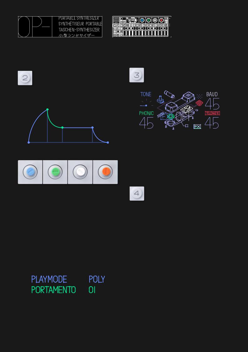
5.3 Envelope
To shape the envelope, press the T2 key.
The envelope controls the amplification of a sound and is triggered when a note is
played. You can control the attack, decay, sustain and release. This is called an ADSR
envelope.
Use the four color encoders to shape the Envelope.
Blue – Attack, Green – Decay. White – Sustain.
Orange – Release
This will be indicated by a color change in the graphical interface as soon as an encoder is turned.
5.4 Play Mode
To enter Play mode press SHIFT while you are in the
Envelope screen which is located under the T2 key. In play mode, you can select if you want your sound to
be Polyphonic, Monophonic, Legato or Unison. In play mode, you also have the portamento
parameter setting.
5
Synthesizer Mode
(Continued)
5.5 Synthesizer E ect
To add an e ect to a sound, press the T3
key. You may toggle an e ect on and o by pressing the T3 key a second time.
To change e ect, press SHIFT + T3. This enters the
e ect browser screen. Use the Blue encoder to scroll through the list and press T2 to make your selection.
5.6 Synthesizer LFO
The LFO lets you modulate any Synthesizer Engine,
Envelope or E ect parameter.
To add an LFO to a sound, press the T4 key.
You may toggle an LFO on and o by
pressing the T4 key a second time.
To change LFO, press SHIFT + T4. This opens a browser screen, with the list of possible LFOs:
BEND – Lets you use the Bender accessory.
CRANK – Lets you use the Crank accessory. ELEMENT – Lets you use external elements like the
built in Microphone, Line in, G-force sensor or FM Radio to modulate a sound. Select the element,
amount, destination and the destination parameter. MIDI – Route external MIDI CC to the OP-1.
RANDOM – randomize all parameters in a module. Set the speed, amount, LFO envelope and destination
TREMOLO – Lets you create di erent types of vibrato e ects to your sound by modulating the pitch and
volume. Set speed, pitch amount, volume amount and LFO envelope curve. The envelope curve applies
an attack or decay curve to the speed of the LFO. VALUE – Use this classic LFO type to change one
parameter only. Set amount, speed, destination and parameter.

NOTE: Turn the ENCODERS all the way for all options under, for example, destination. The encoders click when turned, which doesn’t equal changing a value. Sometimes you need to turn a couple of clicks to change a value.
Example: ELEMENT LFO
As described earlier the Element LFO uses di erent external elements to control any parameter of a Synthesizer engine, Envelope or E ect. Use the Blue encoder to select your source. The options are:
G-force
Mic/Line/Radio
G-force is pretty straightforward, you don’t need to make any further settings. When selecting option Mic/Line/Radio, you need to select the input source. Press SHIFT + Input key to select input and to adjust the gain. If Radio is selected here you may tune in to a radio station for satisfactory results.
For more information about LFOs please refer to the LFO reference section of this manual.
5
Synthesizer Mode
(Continued)
5.7 Changing Sounds
Consider sound selection keys 1-8 as your instant
access keys. To change any of the sound 1-8 presets, press SHIFT + any key from 1 to 8 and a list of all
available sound presets is shown. Select a preset by turning the Blue encoder for Engine type and Green
Encoder for Preset choices.
NOTE: The di erence between changing just a Synthesizer Engine (SHIFT + T1) and a Sound (SHIFT
+ 1-8) is that the later changes all four T1T4 settings.
5.8 Saving a Sound
To save a sound, you have two options:
•DUMP TO TAPE – Use the LIFT key while in Synthesizer or Drum mode. Then switch to Tape, locate empty space on the tape and press the DROP key. The sound will now be converted to sound-data. To recall a sound that was dumped to Tape, press LIFT, switch to Synthesizer or Drum and press DROP.
•SAVE SOUND 1-8 – Tweak your sound on any of the sound slots from 1-8. Hold the sound key for five seconds. Sounds 1-8 are located in the SNAPSHOT folder located inside the Synth and Drum folders. Via USB, you may drag the sound you want to your desktop and rename it, or rename the sound inside the folder. Keep in mind that you may use names with a maximum of ten characters. Avoid uncommon symbols.
PRO-TIP: You may create your own folder and place it
in either Synth or Drum folder to organize your files.
5
Synthesizer Mode
(Continued)
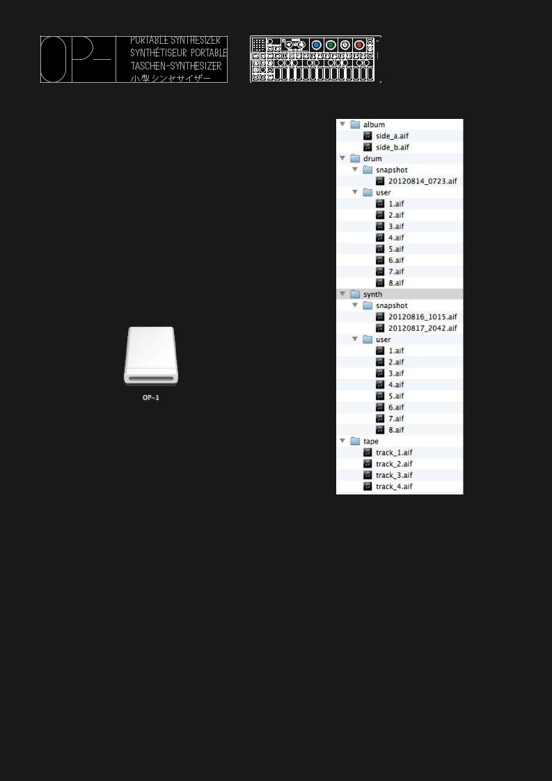
5.9 Sound File structure
The OP-1‘s storage allows you to add files for use for
Synth and Drum sounds. It also lets you collect those files you have recorded in Tape and Album for use
elsewhere. You may also manage your own presets, those which you have made in synth and saved.
These are stored in the “snapshot” folders for Synth and Drum presets respectively, and default to a name
containing their date of creation. Feel free to rename these, limiting the name to ten common characters.
When you connect your OP-1 to your computer and
press SHIFT + COM key and select DISK mode the OP-1 shows up on your desktop:
Double click the disk icon to reveal the internal OP-1
files. All Sounds, Album recordings, Tape Tracks and snapshots show up as .aif files.
NOTE: Sound presets use a special OP-1 version of
the .aif format, which includes BOTH a sound preview and synthesizer data. In other words, the
OP-1 synthesizer engines are not sample based but modeled sounds.
6 Drum Mode
6.1 Drum Mode – Introduction
The Drum Mode - entered by pressing the key with the green drum symbol - is similar to the synthesizer mode. The di erence is it’s use for shorter drum/ percussion sounds. Sounds can be loaded either into the Drum
engine (DRUM), or made using a drum synth (DBOX).
As with Synthesizer mode, pressing the Drum key enables both T1-T4 and Sound selection keys 1-8.
When you have pressed the Drum key, first select a sound (drum-kit) from 1-8 with the Sound keys.
Then use T1-T4 keys to shape the sound:
T1 – Drum engine
T2 – Dynamic Envelope
T3 – E ect
T4 – LFO/G-force
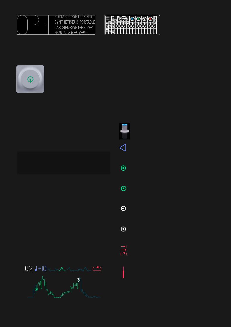
6.2 DRUM Sampler Engine
The di erence compared to the Synthesizer sampler engine is that the Drum sampler has 12 seconds of recording time (vs. 6 seconds in the Synthesizer sampler) and has a layout function which lets you lay out parts of the sample to dedicated keys on the musical keyboard (compared to di erent pitch of the sound when playing the musical keyboard using the Synthesizer sampler).
6
Drum Mode
The basic concept here is to record all drums in a row
and keep that recording to 12 seconds. Then set in and out points of that recording and dedicate it to a
certain key on the musical keyboard.
6.3 Laying out a Drum Kit
To layout a Drum Kit, press any key on the musical keyboard and start to set the In point of the sound.
This can be anywhere on the sample. Then set the Out point and hit the same key on the musical
keyboard. You should now hear the part of the sampling you have dedicated to that key. The tools
you have to set up your drum kit are:
PITCH
Set the pitch of a part by turning the
Blue encoder.
DIRECTION
Press SHIFT and turn the Blue encoder
to change direction of a part.
IN POINT
Set the in point by turning the Green
encoder.
FINE TUNE IN POINT
Press SHIFT and turn the Green encoder
to fine tune the position of the in point.
OUT POINT
Set the out point by turning the White
encoder.
FINE TUNE OUT POINT
Press SHIFT and turn the White encoder
to fine tune the position of the out point.
PLAY TO END, LOOP, PLAY ONCE
Turn the Orange encoder to set the play
mode of a part.
LEVEL
Press SHIFT and turn the Orange
encoder to set the volume level of a part.
NOTE: Remember to always select the key on the musical keyboard where you want to change sound.
 Loading...