

Page 1

TECUMSEH
Main Menu
T E C H N I C I A N ' S H A N D B O O K
This manual covers all Peerless® Gear models as follows:
Right Angle and T Drives (P-91), 100, 600, 601, 700, 800, 801,
820, 900, 910, 915, 920, 930, 940, 1000, 1100, 1200, 1300, 1800,
2300, 2400, 2500, 2600, 2800, MST, VST.
TECUMSEH / PEERLESS
MOTION DRIVE
SYSTEM
TRANSMISSIONS / TRANSAXLES /
DIFFERENTIALS / RIGHT ANGLE DRIVES
Page 2

TABLE OF CONTENTS
Main Menu
Main Menu
CHAPTER 1. GENERAL INFORMA TION
SECTION 1. Model Overview and Terms Used ................................................................ 1 - 6
SECTION 2. Lubrication Requirements ..................................................................................7
SECTION 3. Identifications .....................................................................................................8
SECTION 4. Torque Specifications .........................................................................................9
SECTION 5. Trouble Shooting Table ............................................................................ 10 - 12
CHAPTER 2. TRANSMISSIONS
SECTION 1. 700 Series ................................................................................................ 13 - 16
SECTION 2. 700H Series.............................................................................................. 17 - 19
SECTION 3. 2800 Series .............................................................................................. 20 - 21
CHAPTER 3. TRANSAXLES
SECTION 1. 600 Series ............................................................................................... 22 - 26
SECTION 2. 601 Slow Speed Series ................................................................................... 27
SECTION 3. 800/801 Series ......................................................................................... 28 - 32
SECTION 4. 820 Series ................................................................................................ 33 - 36
SECTION 5. 900 Series ................................................................................................ 37 - 40
SECTION 6. 910 Series ................................................................................................ 41 - 44
SECTION 7. 915 Series / 940 Series............................................................................ 45 - 48
SECTION 8. 920 Series ................................................................................................ 49 - 52
SECTION 9. 930 Series ................................................................................................ 53 - 56
SECTION 10. MST200 Series....................................................................................... 57 - 62
SECTION 1 1. VST205 Series ....................................................................................... 63 - 64
Page
CHAPTER 4. 3-SPEED TRANSAXLES
SECTION 1. 1200 Series .............................................................................................. 65 - 67
CHAPTER 5. FOUR-SPEED TRANSAXLES
SECTION 1. 2300 Series .................................................................................................. 68 - 73
CHAPTER 6. REDUCTION GEAR and DIFFERENTIAL UNIT
SECTION 1. 1300 Series .................................................................................................. 74 - 75
CHAPTER 7. REDUCTION GEAR and DIFFERENTIAL UNITS
SECTION 1. 2400 Series .................................................................................................. 76 - 77
SECTION 2. 2500 Series .................................................................................................. 78 - 81
SECTION 3. 2600 Series .................................................................................................. 82 - 84
CHAPTER 8. DIFFERENTIALS ......................................................................................... 85 - 90
CHAPTER 9. DRIVES ........................................................................................................ 91 - 95
1 100 Series ....................................................................................................................... 96 - 98
CHAPTER 10. SHIFTING ASSEMBL Y ............................................................................ 99 - 101
CHAPTER 11. BEARING and BUSHING SER VICE...................................................... 102 - 103
NOTE: The VST Series is not addressed in this issue with the exception of the brake.
C Tecumseh Products Company
1996
Page 3

CHAPTER 1.
Main Menu
Main Menu
SECTION 1. MODEL OVERVIEW AND TERMS USED
A. TECUMSEH / PEERLESS UNITS
1. GENERAL
Tecumseh/Peerless makes power transmission
gear drives for use in all types of lawn and
garden equipment.
2. IDENTIFICATION OF MODELS
Since acquisition by Tecumseh Products Co.
in 1964, all Peerless assemblies have a model
number identification tag, or stamping. On units
containing axles (transaxles, or reduction gear
and differential units) the identification should
be visible by viewing the case/cover unit from
below and behind as it is mounted in the driven
equipment. If the area is dirt or oil covered,
however, some cleaning may be necessary.
Write down any numbers found in locations
pointed out, then compare with the Master Parts
Manual Div. 8 index. For right angle and “T”
drives, the identification number is stamped
into the housing under the input shaft boss
opposite the cover. On transmissions the
identification number is stamped on the cover
back of the output drive sprocket. On the 100
series differential, the number is stamped either
on cast housing diameter or on the housing
end near axle bushing.
3. TRANSAXLES
A combination of transmission and differential
axle are in one compact unit. Peerless
transaxles are manufactured in many different
gear ratio combinations and from 1 to 7 forward
speeds with one reverse.
A. 600 Series. The 600 series is a lightweight
unit usually used in riding mower or similar
application. The 600 series has a vertical
input shaft at the top of the case. The case
is aluminum, contributing to a considerable
weight saving. Variations in the series (which
determines the specific model number such
as 603, 603A, 609, etc.) includes:
1. Shift lever shape.
2. Axle lengths.
3. Axle machining for wheel hub attachment.
4. Axle housing variations.
5. Size of the brake shaft.
There may be other slight differences,
however, these are present as a result of
product improvement which are not options
to an O.E.M. (Original Equipment
Manufacturer).
B. 800 Series. This unit has 3 to 6 speeds
forward and 1 reverse. The bearings are
oil impregnated bushings with needle
bearings or ball bearings on axles, input
and output shaft.
C. 820 Series. This unit is a heavy duty unit
with 2 to 6 speeds forward and 1 reverse
which can be used with ground engagement
attachments. Sleeved needle bearings are
used in place of oil impregnated bushings
on all shaft ends and ball bearings are
standard on axles.
D. 900 Series. The unit is like the 800 series
transaxle except that the 900 can be 2, 3,
or 4 speeds forward and 1 reverse.
E. 910 Series. This transaxle will offer a
forward and reverse unit. The speed will
change with the use of a vari-drive pulley
arrangement.
F. 915 Series. This unit has 3 to 5 speeds
forward and 1 reverse. This unit has a gear
driven reverse instead of chain driven and
the case is sculpted around the gears.
G. 920 Series. This series of 900 transaxle
offers 3 to 7 speeds forward and 1 reverse.
H. 930 Series. This unit has 3 to 7 speeds
for ward and 1 reverse. The transaxle is
very similar to the 920 series except for
the differential and shifter/brake shaft.
I. The MST Series, (Manual Shift Transaxle)
200 is a sealed unit which uses 16 oz. of
80W90 gear lube (part #730229A). The MST
series is available with up to 6 speeds forward
and one reverse. It has a sculptured case
and cover.
J. VST/1800 Series. This transaxle
incorporates a hydrostatic pump and motor
built into the unit. The prefix letters stand
for Variable Speed Transaxle (VST). This
unit contains two separate oil reservoirs,
one for the pump and motor containing
airless synthetic oil and the other contains
EP90 gear oil for the differential gears. This
unit sealed for life and not serviceable at
this time.
K. 1200 Series. The distinguishing feature of
the 1200 series transaxles is that the axle
support housings are pressed from the
inside of the case and cover, therefore,
are not readily removable until the unit is
completely disassembled. The casing is
cast iron for rugged, longtime wear.
1
Page 4

L. 2300 Series. Generally similar to the 1200
Main Menu
Main Menu
series transaxle. The distinguishing features
are a more massive casing, and a larger
shift lever opening machined area. The
obvious difference from the standpoint of
application is that these units have four
speeds forward and will be found on
equipment that can be used with ground
engagement operations.
aluminum and the differential gears are sintered
metal or cut steel. The differential pin is held in
place by the four retaining capscrews. Oil Lite
bushings reduce friction during differential operation.
The drive sprocket is part of the unit, which
depending upon application, can be in any of several
diameters in size, thus having a different number
of gear teeth. This sprocket is often supplied by
the O.E.M.
NOTE: The transaxles described in paragraphs K
and L, are fairly similar in appearance, but do have
specific recognizable characteristics. Both these
units have cast iron bodies for rugged application,
although the 2300 series is the only unit that can
be used in ground engaging equipment
applications.
3. REDUCTION GEAR AND DIFFERENTIAL UNITS
GENERAL
These units do not have a transmission function
characteristic of transaxles, but rather, are units
to reduce input speed and torque to a suitable axle
speed and torque. The hydrostatic units which match
to these units perform the transmission function.
a. 1300 Series. This unit is the hydrostatic
counterpart of the three-speed forward unit
(1200). It has an aluminum casing and pressed
through axle support housings, characteristic
of the 1200 series. The hydrostatic unit is of
Eaton manufacture and is not serviced by
Tecumseh Service Dealers.
b. 2400, 2500 & 2600 Series. This series of
hydrostatically driven reduction gear and
differential units can be used in ground engaging
operations such as plowing. The hydrostatic
unit is manufactured by Sundstrand Corp. in
LaSalle, Ill.
3. TRANSMISSIONS
These units as manufactured by Peerless consist
of the shifting mechanism to take a constant input
shaft speed and reduce it to the desired output
speed. The differential or axle unit is connected
through a chain drive.
a. 700 Series. This unit can be 3, 4 or 5 speeds
forward and 1 reverse. The brake system can
be mounted on either side of the unit.
b. 700 “H” Series. This unit is built with almost
all interchangeable parts with in it’s two cases
except that this will be a “H” shift pattern. This
unit has 3 or 4 speeds forward and 1 reverse.
5. ANGLE DRIVES
These units are used primarily to change the direction
of drive at the point where the working equipment
attaches.
They can be assembled for right or left hand rotation
so that they can be used in various combinations
for synchronous operation.
a. Right Angle Drive. These units consist of input
shafts, output shafts, and the beveled gearing
necessary to change the direction of power
transmission at right angles. By positioning the
drive bevel gear on the input shaft nearest the
input end, opposite rotation will be attained from
that of switching the beveled gear around to
the side away from the input end of the shaft.
Casing and bearings are identical. A cover
identifies each unit as being either a left hand
(LH) or a right hand (RH) right angle drive.
b. “T” Drives. The “T” drive is essentially the
same as the right angle drive except that the
input shaft extends out the other side of the
case to transmit power in the same line to
additional right angle drives or other equipment.
c. Shafts, Couplings, Pulleys, etc. These items
are part of the total transmission unit and are
used to connect angle drives, and other
attachments. The serrated couplings match the
serrations on the shafts of the angle drives or
on connecting shafts.
6. TERMS USED
AXLE - The shaft which connects the wheel or
hub to the differential unit and transmits force back
to the wheels. Sometimes axle refers to the
differential and axle combination as in the term
TRANSAXLE.
AXLE HOUSING (or AXLE SUPPORT) - An
extension of the case and cover to support the
outer ends of the axles. Because the housing is
visible, it is often the best means of distinguishing
the series in question.
4. DIFFERENTIALS
2
c. 2800 Series. This unit is built to work on the
2600 series. It is used as a P.T.O. transmission
to run external equipment.
The only self contained differential/axle unit built
by Peerless is the 100 series. It features hardened
axle shafts of various length and machined for various
methods of hub attachment. The case is cast
BEARING BLOCK (Strip) - Used to support the
ring gear of the differential.
BEVEL (on a gear - different from bevel gear) Roundness of the meshing sides of gear teeth allow
easy shifting. Because this is about the only
allowance made to make easier shifting, the unit
should be stopped before the shift to keep these
spur gears from getting chewed up.
Page 5

BEVEL GEAR - A gear with teeth ground on a
Main Menu
Main Menu
diagonal so that when it meshes with a second
bevel gear, power is transmitted at an angle. If the
angle is 90o, the gear is known as a MITER GEAR.
HEAD ASSEMBLY - A complete unit containing
all parts of one right angle or “T” drive assembly of
a right angle drive system. The head assembly is
permanently lubricated and sealed.
BEVEL PINION - The smaller of two meshed bevel
gears in a gear train.
BRAKE (or BRAKESHAFT) - The shaft on a Peerless
unit (Transaxles and Transmission) to which a braking
system may be attached. It is in the gear train
with the differential to stop it when the operator
“brakes”. It is usually larger in diameter than the in
put shaft due to its function of taking shock loads
experienced in braking.
CASE - That part of the unit “casing half” which
contains the shift lever and input shaft openings.
The other “half” is the COVER because the
reassembly must be done into one or the other
depending upon the series.
CHAMFER - Diagonal milling at the corners of gear
teeth to remove sharp edges. The usual reason
for chamfer is to eliminate the possibility of hardened
gears chewing softer metal.
COUNTERSHAFT - Splined shaft which holds gears
that are in constant mesh with shift gears and
transfer power flow from input to shift gears.
COUPLING - A sleeve to connect two serrated
shafts in the same axial plane. Used in right angle
drive systems or in connecting the hydrostatic drive
to the input shaft on 2400 series transaxles.
COVER - That part of the unit “casing half” which
contains the brake shaft opening (except the 600
series in which all openings are in the CASE as
described in CASE above). The case and the cover
switch sides depending upon whether the transaxle
is right or left hand drive.
DIFFERENTIAL GEAR BOLTS - Through bolts
holding the differential parts together. The heads
of these bolts must be opposite the output shaft
gear (except in the 2400 series). This is an early
check to see that the unit is being assembled
correctly.
DOWEL PIN - Alignment pin is used to align the
case and cover and other parts in a transmission
or transaxle. The dowel should be tapped in to hold
the parts in alignment before tightening the retaining
screws. Failure to install dowel pins first will usually
lead to a unit that binds after assembly.
DUO-TRAK* DIFFERENTIAL (*Trademark -Illinois
Tool Works) - A type of differential which increases
torque to the tractive wheel to keep it turning,
however in situations where differentiation is
necessary (as in turning) the unit acts much like a
regular differential.
EQUIPMENT - The complete assembly (riding
mower, tractor, etc.) is built by a manufacturer, a
part of which is the Peerless unit. A check of the
equipment manual is recommended prior to servicing
the Peerless unit.
IDENTIFICATION NUMBER - See MODEL
NUMBER
IDLER - A gear used in a gear train to transfer
motion or direction. The gear rotates independently
of the shaft upon which it is located.
INPUT OR INPUT SHAFT - The part of a Peerless
unit which is always connected to the drive. Its
rotational speed is dependent on the driving
mechanism. All parts of the input system are always
in mesh with input shaft and turn whenever it turns.
LIMITED SLIP DIFFERENTIAL - See DUO-TRAK*
DIFFERENTIAL.
MITER GEAR - One of a pair of interchangeable
bevel gears with axles at right angles. Since all
bevel gears are miter gears in Peerless units, the
terms can be the same.
MODEL NUMBER - The identifying number of a
Peerless unit which will permit selection of the proper
parts to repair that unit.
NEUTRAL SPACER - Single or split collar between
forward gears and reverse that shift keys engage
when unit is in neutral.
OIL SEAL, DOUBLE LIP - An oil seal with two
sealing surfaces to prevent entrance of foreign matter,
and leakage of lubricant.
OIL SEAL, QUAD RING - A seal with two external
and two internal sealing lips. Used in the shifter
housing.
OIL SEAL, SINGLE LIP - An oil seal with one
sealing surface to either prevent entrance of foreign
matter or prevent leakage of lubricant.
OUTPUT, OR OUTPUT SHAFT - On a transaxle,
the shaft that contains the output pinion which is
in direct mesh with and drives the differential. In a
transmission, the exposed shaft which contains
the sprocket for driving the axles. The output shaft
is driven by the large OUTPUT GEAR.
OUTPUT SHAFT GEAR - The importance of defining
this gear is to point out that it must be opposite
the differential bolts in Peerless units (except the
2400 series). The output gear assembles into
transaxle cover.
PEERLESS UNIT OR UNITS - The complete
Peerless assembly which is part of the
EQUIPMENT. The Peerless unit is that assembly
being described.
REDUCTION GEAR AND DIFFERENTIAL UNIT A Peerless unit that reduces a high RPM input speed
to a suitable axle speed without the use of a
transmission. Since there is a single gear train,
there is a single input speed to output speed ratio,
however, axle speeds are infinite, depending upon
input speed.
3
Page 6

REVERSE IDLER (915 Series) - Gear between
Main Menu
Main Menu
reverse gear of countershaft and reverse gear of
shifter/brake shaft that allows unit to operate in
opposite direction.
SHIFTER GEAR, LARGE - This gear transmits
1st (low) and reverse (1st, 2nd and reverse in 4speed units) gear ratio force to the output shaft. It
is beveled on both sides.
REVERSE IDLER - A gear added to the gear train
so when in mesh, reverses the direction of all gears
driven after it. Its number of teeth also affects the
reverse gear ratio. The center gear of the three
gear cluster always is in mesh with the REVERSE
IDLER, and the large shifter gear always shifts
into it.
RIGHT ANGLE DRIVE - Interchangeable with HEAD
ASSEMBLY. The major operating parts are a pair
of miter gears. A system consists of other right
angle or “T” drive head assemblies and connecting
hardware.
SEAL - A mechanism which stops leakage. It can
be a rubber ring, as in an “O” ring or “Quad” ring, a
sealing type ball bearing, or most commonly, a rubberlike sealing surface encased in a metal form.
SEAL RETAINER - Found on some models of
transaxles and on right angle drives. The center of
the retainer is bored to the size of the outer diameter
of the seal. On transaxles the retainer acts to position
the differential. In the casing on right angle drives,
it acts as the end cap of the case and is secured
with four capscrews.
SHIFT COLLAR - Round collar which retains shift
keys onto the shifter/brake shaft. The shifter
assembly pin (or pins) slide into the groove on the
collar to activate the shift keys.
SHIFT GEARS - Gears on shifter/brake shaft that
are in constant mesh with spur gears of counter
shaft. The shift gear in which the shift keys engage
determines the speed of a transaxle.
SHIFT KEY - One of either two or four metal spring
steel keys, which are held in the keyways of the
shifter/brake shaft, by a shift collar. The shift keys
are used to slide through the shift gears and engage
the desired gear or speed.
SHIFT KEYWAY - One of either two or four slots
in the shifter/brake shaft for the shift keys to slide
through for gear selection.
SHIFT WASHER - Washer on which one side has
a 45o inner diameter chamfer or rounded inner
diameter. Shift washers depress keys for shifting
from one gear to another.
SHIFTER ASSEMBLY - Consists of shift rod, shift
fan, shift arms and shift pin or pins.
SHIFT LEVER - The lever by which the operator
manually changes the shifter gears to vary reduction
speed ratios in the transmission. The configuration
of the lever is variable and is often the only reason
for a unit being given a new model number.
SHIFTER GEAR, SMALL - This gear transmits
2nd and 3rd (3rd and 4th in a 4-speed unit) gear
ratio force to the output shaft. It can have two different
tooth diameters and be beveled on the outside of
each, or it can have a beveled spline to engage
3rd (or 4th) gear through a splined shaft.
SHIFTER HOUSING - This housing contains the
shift lever and must be reinstalled in the proper
position to function correctly. If housing does not
already have guide marks, scribe the shifter housing
and transmission case before removal.
SHIFTER ROD - One of two similar smooth rods
of equal length with grooves which match the fork
position to meshed positions of the shifter gears
and gears of the three gear cluster. Each rod has a
snap ring to act as a fork stop, but can also be
used to determine how the fork is assembled to it.
SHIFTER SHAFT - A splined shaft which meshes
with the internal splines of the shifter gears, to
transmit force to the output shaft gear.
SHIFTER STOP - A stamped metal plate which
separates the shifter forks. The stop has a notch
cut in it which corresponds to the neutral position
on the shifter forks and rod. The shifter lever must
return the engaged fork back to neutral before it
can cross to actuate the other fork.
SPROCKET - A geared wheel designed to turn a
link chain drive. Various numbers of teeth (hence,
sprocket diameter) are available to change output
ratios.
SPUR GEAR - A gear having the shaft bore and
teeth in a parallel plane.
“T” DRIVE - A right angle drive with an input shaft
extending thru the case to transmit power axially
in a second direction to the right angle output. On
“T” drive with dissimilar input and out end of the
input shaft, care must be taken to insure that the
parts do not run in reverse when reassembled.
THREE GEAR CLUSTER - A 3 gear assembly in
mesh with the input shaft. The gears are of different
sizes to change gear ratios when meshing with
the two shifter gears.
THRUSTER RACE - A thrust washer in which the
outer edge is cupped to fit the outer diameter of a
thrust bearing. This fit positions the thrust race
concentric with the axle diameter. It further acts
as a thrust washer.
THRUST WASHER - A flat polished surface
separating metals of different hardness. It also acts
as a spacer between shafts and the case and cover.
4
SHIFTER FORK - A mechanical arm which moves
on rod to position the shifter gear at an exact spot
axially along the shifter shaft.
Page 7

TRANSMISSION - A system of varying sized gears
Main Menu
Main Menu
in a case, some of which can be slid along a shaft
to vary gear ratio in the gear train. The net effect
is to change speeds to the rear wheel according to
the type of work being done.
UNIT - See PEERLESS UNIT.
8. GENERAL SERVICING PROCEDURES
1. Introduction:
The following service procedures should be
understood and practiced whenever service must
be performed on a Peerless unit.
2. Before removal of unit from equipment, look for:
a. Loose drive belts.
b. Improperly adjusted or badly worn clutch.
c. Loose or lost set screws and/or sheared keys
in drive and driven pulleys.
d. Oil saturated drive belts and clutches.
e. Bad operating habits, such as clutch riding.
f. Oil leaks. If found, refer to paragraph F.
g. Any trouble, which might be pointed up by
operating the unit and equipment, IF POSSIBLE.
h. Review Service Bulletin 304.
3. Removal of the Peerless unit from the equipment:
a. Jack up equipment so that transaxle is
accessible. Use wood blocks to prevent
equipment movement. Do not use bricks,
cement or cinder blocks.
b. Visually inspect Peerless unit for oil leaks,
cracked housing, binding or rubbing of parts,
or other symptoms of malfunction.
c. Use a jack under the Peerless unit to support
it’s weight when attachments are removed.
d. Remove wheels, drive belts, pulleys, chains
and other associated equipment from Peerless
unit. Be aware of positioning of parts. Scribe
mark, if in doubt, to be able to reassemble
parts quickly.
e. If shifter lever will interfere with unit in any way,
remove it before unit is removed.
f. Remove attaching hardware holding Peerless
unit to equipment at case, cover, axle supports,
shifter or by other means.
g. With Peerless unit free and supported, remove
it from the area of equipment to the work bench.
4. Preparing for disassembly:
a. Visually inspect for evidence of oil seepage,
tampering, misalignment, freedom of rotating
shafts, etc.
b. Clean unit thoroughly of dirt, oil, debris.
c. Remove shift housing and drain oil from unit.
Observe oil to see if metal particles are present.
d. Check axle shafts carefully for smoothness.
Use a stone or suitable abrasive to rub down
high spots and eliminate rust or paint.
e. Check model number at appropriate spot. It is
advisable to have the exploded parts view handy.
f. Have seal sleeves, driver, tools, shop cloths
and informational material at hand.
9. OIL LEAKS, SEAL AND GASKET SERVICE
Peerless units contain various styles and sizes of
oil seals. The function of any oil seal can be:
1. To seal inward (single lip) to prevent lubricant
leaks.
2. To seal outward (single lip) to prevent lubricant
leaks.
3. To seal both inward and outward (double lip).
Some seals are spring loaded. That is a spring creates
a positive light compressing action to insure that the
seal lip will make a 100 contact around the shaft. All
Peerless seals, seal on the inner diameter.
1. Other than leaking seals, gaskets and “O” rings,
leakage can occur due to a cracked case or
cover, flats on shafts, porosity (rarely, if ever),
and worn bushings and shafts.
2. Single lip inward sealing can be salvaged by
the use of the proper seal protector when pulling
the seal over a shaft. Outward sealing seal
(both single and double lip) must be replaced
since there is no assurance that the initial sealing
surface can be protected.
3. If you can’t protect the sealing lip, replace the
entire seal. The cost of the seal is small in
comparison to a return repair due to reuse for
seals.
4. Check seals for cracks, scuffs, cuts and
distortion. Check seal areas for evidence of
oil leak both at sealing surface and between
metal-to-metal contact surface areas.
5. Some seals have a “Redicoat” sealant applied,
while others may need a thin coat of this or a
similar sealant.
6. The surface over which the seal lips must slide
must be free of all cuts, scratches, high spots,
or rust. The shafts should be smooth, shiny
and a thin film of light oil applied. Sleeves should
be used to clear keyways, splines, or other
sharp edges machined into shafts.
10.TORQUE VALUES TROUBLE SHOOTING
1. All torque values must be applied. The torque
value for any fastener will be found in the
assembly instruction where that fastener is
used. All torque specs. will be found in Section
4.
2. Overtightening can strip threads, compress the
gasket excessively, and possibly cause binding.
3. Cross tightening sequence to half the torque
then finally to full torque value.
4. Under tightening Oil leakage, loosening of
attaching parts, and possible shifting of the
internal parts causing complete failure.
5
Page 8

5. Since all bolts are readily accessible there is
Main Menu
Main Menu
no reason that a torque wrench cannot be used
for all bolt and screw tightening.
11.TESTING
The absence of binding and oil leakage are the
best indications that the unit has been properly
reassembled. Though other, more elaborate tests
can be done, this would be the prerogative of the
servicing agency, since the following checks are
considered adequate.
With the shift forks in neutral, rotate both axle ends
in the same direction. They should turn smoothly
although a little effort may be necessary. The brake
shaft should rotate whenever the axles turn together,
but in neutral, the input shaft should not turn. By
moving any shifter gear into mesh, a greater drag
should be felt on the axles, and both the input and
brakeshaft should turn. For ease in turning of the
various shafts, insert a tool (such as a punch or a
socket head screw key) into the keyway, however,
do not force if shaft is binding. Reason for unit
binding:
1. Re-used or lack of gasket.
2. Oil seal retainers installed backward.
3. Mis-installed thrust washers.
4. Differential installed backwards.
5. Mis-assembly of shifting parts.
6. Mis-placement of spacers.
7. Foreign matter blocking gear teeth mesh.
8. Shifter stop installed backwards.
9. Input shaft not completely in case.
10. Mis-alignment of case and cover. Align with
dowels before tightening cap screws.
6
Page 9
SECTION 2. LUBRICATION CHART
Main Menu
Main Menu
Check the Peerless unit model number before filling
with lubricant. There may be a difference in the quantity
recommended. This is dictated by the design of the
vehicle and the position of the Peerless unit in it.
TRANSAXLES
Model
No. Quantity
600 24 oz./710 ml Oil
800 30 oz./887 ml Grease
801 36 oz./1065 ml Grease
820 36 oz./1065 ml Grease
900 26 oz./769 ml Grease
910 18 oz./532 ml Grease
915 10 oz./296 ml Grease
920 30 oz./887 ml Grease
930 30 oz./887 ml Grease
1200 48 oz./1420 ml Oil ††
1305
1309 32 oz./946 ml Oil
1313
1301
1302
1303
1304
1306
1307
1308
1310
1311
1312
1314
1315 44 oz./1301 ml Oil
1316
1317
1318
1320
1321
1322
1325
1328
1329
1319
1323 24 oz./710 ml Oil
1326
1327
MST 16 oz./473 ml Oil
2300 64 oz./1892 ml Oil
2400 32 oz./946 ml Oil
2500 †
2600 †
TRANSMISSIONS
Model
No. Quantity
700 12 oz./355 ml Grease
700H 12 oz./355 ml Grease
2800 †
Grease: Bentonite Grease
Part Number 788067B
Oil: SAE E.P. 80W90 Oil
Part Number 730229A
† Refer to O.E.M. Mechanic’s
Manual for type of lubricant
†† To be filled through shift lever
opening
RIGHT ANGLE
AND T DRIVES
Model
No. Quantity
All Models
Except * 4 oz./118 ml Grease
*1408-P91
*1409-P91
*1410-P91
*3002 3 oz./89 ml Grease
*3003
*3028
*3029
*3035
1000 Series 6 oz. / 180 ml
SAE E.P. 80W90Oil
1100 16 oz./473 ml Oil
DIFFERENTIALS
All Models 3 oz./89 ml Grease
TWO SPEED AXLE
All Models 2 oz./59 ml Grease
THREE SPEED AXLE
All Models 2 oz./59 ml Grease
NOTICE
7
Page 10
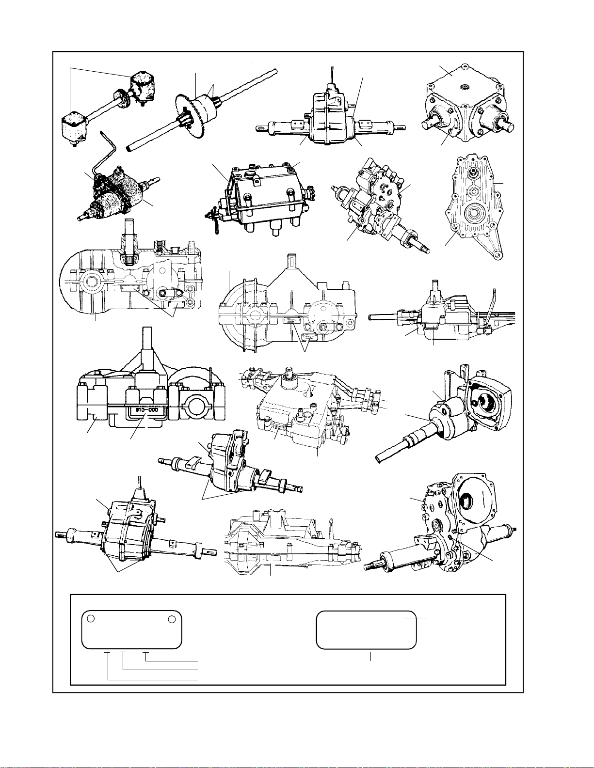
SECTION 3. IDENTIFICATION
Main Menu
Main Menu
RIGHT ANGLE DRIVES
600 SERIES
810 SERIES
801 SERIES
A or B
A
100 SERIES
700 SERIES
A or B
900 SERIES
920 SERIES
930 SERIES
A or B
1100 SERIES
1200 SERIES
A or B
A
2600 SERIES
910 SERIES
A
A
A
2800 SERIES
A
A
915 SERIES
2300 SERIES
A or B
SAMPLE (OLD STYLE)
PEERLESS
1 275 1374
A 2400 SERIES
MOD 506
A
A or B
MST and VST
Individual Serial Number
Manufactured on the 275th Day
Manufactured in 1991
820 SERIES
2500 SERIES
SAMPLE (NEW STYLE)
MST205- l l l
l l l l l l l l l l
SERIAL 6 0 0 2
Serial Number Julian Date
1300 SERIES
A
A
Specification Number
Manufacturers
Requested Features
THE MODEL NUMBER WILL BE FOUND ON: A. Metal tag or decal attached to unit as illustrated.
8
Early Models were not identified with a model number on the unit.
B. Stamped on unit as illustrated.
Identification Number Locations
Page 11
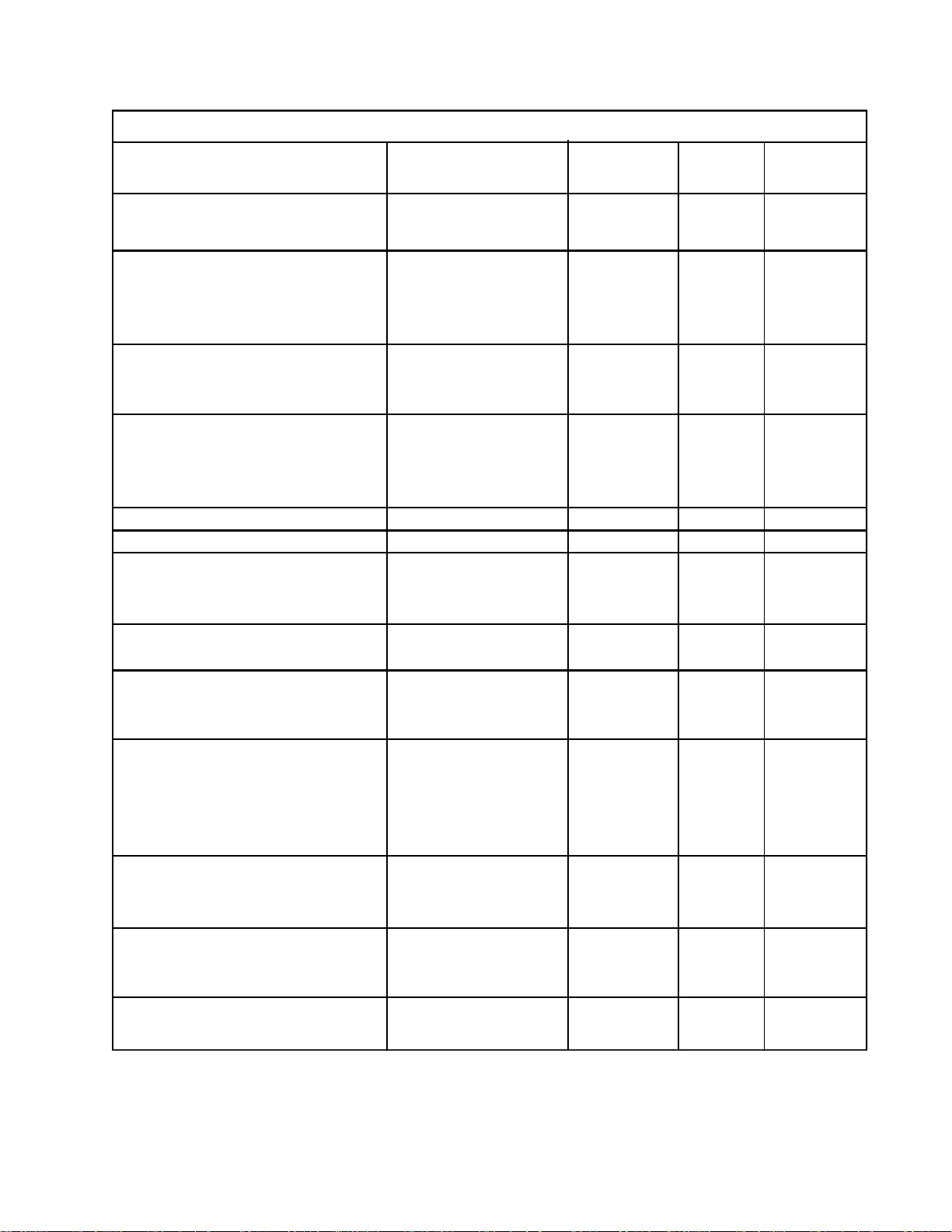
SECTION 4. TORQUE CHART
Main Menu
Main Menu
TORQUE VALUE
MODELS
PART AFFECTED IN-LBS FT-LBS NM
Bolt 5/16-18 (Housing) 100 Series 228-264 19-22 25.8 - 29.9
Nut 5/16-18 (Housing) 100 Series 120-156 10-13 13.6 - 17.7
Bolt 1/4-20 (Case to Cover) 600 Series 84-108 7-9 9.5 - 12.2
Bolt 5/16-18 (Axle Support Housing) 600 Series 156-180 13-15 17.7 - 20.4
Bolt 1/4-20 (Shift Lever Housing) 600 Series 84-108 7-9 9.5 - 12.2
Bolt 1/4-20 (Brake-Disc) 600 Series 84-108 7-9 9.5 - 12.2
Bolt 1/4-20 (Case to Cover) 800 & 900 Series
(Except 820) 90-100 7.5-8.3 10.2 - 11.3
Bolt 1/4-20 (Brake-Disc) 800, 900 & MST Series 85-110 7.1-9.2 9.7 - 12.5
Bolt 5/16-18 (Case to Cover) 820 Series 180-216 15-18 20.4 - 24.5
Bolt 1/4-20 (Bearing Cap) 820 Series 90-100 7.5-8.3 10.2 - 11.3
Bolt 1/4-20 (Differential) 820 Series 84-120 7-10 9.5 - 13.6
Bolt 1/4-20 (Brake Disc) 820 Series 85-110 7.1-9.2 9.7 - 12.5
Bolt 5/16 x 18 1100 Series 180-216 15-18 20.4 - 24.5
Bolt 5/16 x 18 2800 Series 180-216 15-18 20.4 - 24.5
Bolt 1/4-20 (Case to Cover) 1200 Series 96-120 8-10 10.9 - 13.6
Bolt 1/4-20 (Shift Lever Housing) 1200 Series 84-108 7-9 9.5 - 12.2
Bolt 1/4-20 (Differential) 1200 Series 84-120 7-10 9.5 - 13.6
Bolt 1/4-20 (Case to Cover) 1300 Series 90-110 7.5-9.2 10.2 - 12.5
Bolt 1/4-20 (Differential) 1300 Series 84-120 7-10 9.5 - 13.6
Bolt 1/4-20 (Case to Cover) 1400 Series 96-120 8-10 10.9 - 13.6
Bolt 1/4-20 (Shift Lever Housing) 1400 Series 84-108 7-9 9.5 - 12.2
Bolt 1/4-20 (Differential) 1400 Series 84-120 7-10 9.5 - 13.6
Bolt 1/4-20 (Case to Cover) 2300 Series 96-120 8-10 10.9 - 13.6
Bolt 1/4-20 (Shift Lever Housing) 2300 Series 96-120 8-10 10.9 - 13.6
Bolt 5/16-18 (Axle Support Housing) 2300 Series 180-216 15-18 20.4 - 24.5
Bolt 1/4-20 (Differential) 2300 Series 84-120 7-10 9.5 - 13.6
Bolt 3/8-16 (Axle Support Housing) 2300 Series 240-312 20-26 27.2 - 35.4
Bolt 1/4-20 (Case to Cover) 2400 Series 96-120 8-10 10.9 - 13.6
Bolt 1/4-20 (Axle Support Housing) 2400 Series 96-120 8-10 10.9 - 13.6
Bolt 1/4-20 (Differential) 2400 Series 84-120 7-10 9.5 - 13.6
Bolt 5-16/18 (Case to Cover) 2500 Series 180-216 15-18 20.4 - 24.5
Bolt 3/8-16 (Differential) 2500 & 2600 Series 420-480 35-40 47.6 - 54.4
Bolt 1/2-13 (Axle Support Housing) 2500 & 2600 Series 720-780 60-65 81.6 - 88.4
Screws No. 10-24 (Cover) R.A.D. 20-24 1.6-2 2.2 - 2.7
Bolts 1/4-20 (Retainer Cap) R.A.D. 90-110 7.5-9.2 10.2 - 12.5
NOTE: On all units containing two jam nuts securing brake lever, Hold bottom nut and torque top nut to 100
in. lbs.
Differential Bolts 7 ft. lbs. - 9.5 NM
“T” Drive Bolt 8-11 ft. lbs. - 10.9 - 15.0 NM
“T” Drive Cover Screw 20-24 in. lbs. - 2.24 - 3.7 NM
9
Page 12

SECTION 5. TROUBLE SHOOTING TABLE
Main Menu
Main Menu
THE FIRST RULE IN TRANSAXLE TROUBLE SHOOTING IS TO ISOLATE THE PROBLEM
TO THE TRANSAXLE. CHECK FOR PROPER ADJUSTMENT OF BELTS, BRAKE,
CLUTCH, SHIFTER AND LINKAGES. CHECK PULLEYS FOR SHEARED RETAINERS
AND PROPER BELT DISENGAGEMENT. IF PROBLEM IS RELATED TO SHIFT
DIFFICULTIES REMOVE DRIVE BELT AND RECHECK SHIFTING TO ASSURE
PROBLEM IS NOT WITH ASSOCIATED EQUIPMENT.
All In-Line Shift Models 700, 800, 900, or MST Series
Shifting force or effort should be the same with the engine running or not running. If not equal, check
the following area's: clutch adjustment, brake adjustment, belt release and belt guide positioning.
The transaxle and transmission models listed above are in-line shift mechanical gear drive models that use
shift keys to engage a desired gear to lock and rotate with the shaft. This type of unit requires the transaxle
or transmission to be in a no load condition (de-clutched) when gear selection occurs. De-clutching allows
the unit to have the input and brake forces removed from the gears and shift keys, which allows the unit to
turn freely. Improper shifting (shifting while on an incline, shifting while towing any type of load, or shifting
without de-clutching) forces the shift keys to engage into a gear that is in a loaded condition. Improper
shifting is considered abuse because it leads to pre-mature wear and failure of the shift keys and drive gears.
Tecumseh's limited warranty covers only transaxle or transmission failures that are the result of a defect in
the material or workmanship of the unit, not failures caused by abuse or wear.
Some Original Equipment Manufacturers (OEMs) use these transaxles and transmissions in lawn tractors
that do not use a foot operated clutch. These lawn tractors combine the clutch release mechanism with the
hand operated gear shift lever. When the gear shift lever is moved through the shift gate from the gear
engagement position toward the neutral position, the attached clutch linkage moves the idler pulley to release
all input drive belt tension from the transaxle input pulley. With the drive belt released from the transaxle
input pulley (de-clutched), the transaxle is free to turn under a no arrangement include: shifting while on an
incline, shifting the unit while towing any type of load, or shifting is considered abuse that results in premature shift key and gear wear and failure, not a defect in the material or workmanship of the Peerless unit
and is not covered under Tecumseh's limited warranty.
The following illustrations show gear, shaft and key damage caused by improper shift and / or linkage out of
adjustment. These examples show evidence of wear or damage that is not considered a defect.
Use the following procedure to determine if a hard shifting condition is caused by the shifter/clutch linkage or
an internal problem in transaxle or transmission.
On level ground, start the engine and allow the engine to run. Using the OEM supplied linkage, de-clutch the
foot operated clutch and shift the gear shifter, or on units equipped with a hand operated gear/clutch shift
lever, shift the transaxle or transmission. If shifting is difficult, try shifting the unit with the engine shut off.
If the unit shifts freely through each gear with the engine shut off, the cause of the shifting problem is
external to the unit. DO NOT REMOVE THE TRANSAXLE. Check the clutch, shifter, and brake linkage for
the proper adjustment. Use the guidelines provided by the OEM to check for the correct linkage positioning.
Hard shifting with the engine shut off can be caused by:
1. Bent or binding shift lever or linkage
2. Shift linkage out of adjustment
3. Corrosion in the transaxle or transmission
4. Damaged shift keys, gears, or shifter brake shaft
5. Belt guides missing or improperly adjusted to close or to far away (see equipment manufacturer
specs)
NOTE: DO NOT REMOVE TRANSAXLE UNTIL YOU HAVE CHECK ITEMS 1 AND 2.
If the cause is internal, remove the unit from the tractor, disassemble, and determine the cause of the failure.
10
Page 13
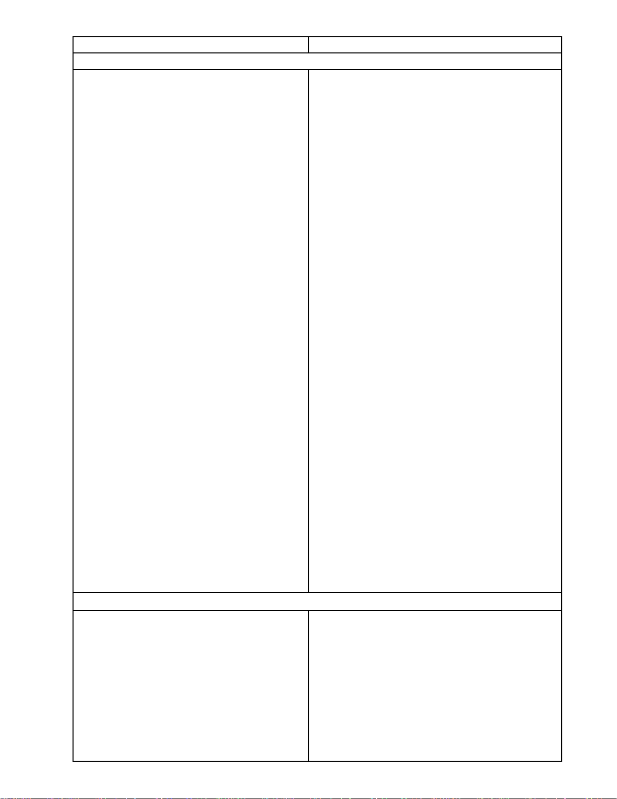
CAUSE REMEDY
Main Menu
Main Menu
UNIT CANNOT BE SHIFTED (OR DIFFICULT TO SHIFT)
Gears improperly installed Review positioning of gearing.
Forks and Rod assembly incorrectly installed Remove assembly. Recheck and correctly position parts.
Axle Housing not installed or not tightened Seal retainers are not properly sealed. Tighten axle housing
bolts.
Same items covered under heading,
Axles cannot be turned (same direction) Review remedy listed
while unit in Neutral gear’’.
Shifting lever improperly positioned Determine if finger of shifting lever is correct for the
unit and is correctly installed. Make sure shift lever
housing has required gasket.
Shifting keys broken or damaged Replace keys and check unit for other damage.
Shifting washers in backwards Chamfered or rounded side of washer must be toward
keys.
Shifter/Brake shaft keyways damaged Remove nicks and burrs from keyway.
Shift lever housing misaligned to case Check if alignment marks on unit are correctly positioned.
Also, determine if bend on shaft is in correct position.
Parts missing Install missing parts.
Equipment clutch not disengaging Adjust clutch according to equipment instruction.
Shifter stop assembled backwards Determine that notch in STOP aligns with shifter forks
in NEUTRAL position.
Chamfer on shift gears on wrong side Check that bevels on shifter gears are correct (fork
flanges should be toward each other). On 3 gear cluster,
small gear and medium gear chamfers go down toward
big gear.
Improper fit of case to cover Recheck positioning of thrust washers. A misplacement
or omission of washer can cause binding.
Dowel pins not installed Check unit for correct assembly of parts.
Gears improperly installed Check unit for correct assembly of parts.
Input shaft not properly installed Input shaft spline must be fitted into gear and must be
tapped completely into the case.
Differential installed improperly Re-check positioning of bolts in differential must be
opposite output shaft gear (except 2400).
Seal retainers improperly positioned Check that seals are correctly installed.
UNIT IS NOISY
Gearing is overly noisy chatter, etc. Check oil level.
Metallic pieces and/or other foreign objects in unit Remove bits of broken metal, loose washers, etc.
Worn gears Remove and replace with new gears.
Worn bearings mainly input shaft ball bearing Replace bearing.
11
Page 14
TROUBLE SHOOTING TABLE (Continued)
Main Menu
Main Menu
CAUSE REMEDY
UNIT JUMPS OUT OF GEAR
Shifting lever improperly assembled in housing Disassemble shifting lever and check for proper assembly.
Teeth of gears are worn beyond tolerances Replace worn gears.
Spring in shifter fork weak or broken Replace spring.
Attaching screws for shift lever and housing Torque screws to 10 ft. lbs.
assembly not properly torqued
Shifter/Brake shaft improperly assembled Reassemble properly
Keys weak or worn Shift gears damaged. Replace keys/Shift gears.
Shift lever bent and hitting unit frame Replace shift lever.
Shift rod grooves worn Replace shift rods.
Shift rod of improper length or grooving installed Check rod length. Replace with correct part.
Constant mesh gears improperly installed on Reposition gears.
counter shaft.
AXLES CANNOT BE TURNED (SAME DIRECTION) WITH UNIT IN NEUTRAL GEAR
Axle housing not installed (or not tightened) Seal retainers are not properly seated. Tighten axle housing
bolts.
Burrs on gearing Remove gear and hone with a stone.
Parts missing Install missing parts
Broken shifter stop allowing unit to be shifted into Replace snap rings on shift rod out of groove.
two speeds at the same time
Thrust washers in wrong position Recheck thrust washer and reposition, if wrong.
Bearings not pressed in deep enough Use the proper bearing tool to seat the bearing.
UNIT DOES NOT DRIVE
Differential bevel gears broken Replace
3 gear cluster countershaft key sheared in Replace.
Model 600
Stripped teeth on gears Replace.
Keys sheared in drive pulleys Replace.
Broken input gear Replace.
Shift keys broken Replace keys/check keyways and shift gears.
Reverse chain broken (reverse only unless chain Replace chain.
becomes wedged)
12
Page 15
CHAPTER 2. TRANSMISSIONS
Main Menu
Main Menu
SECTION 1. TRANSMISSIONS 700 SERIES
CAUTION
TO AVOID PREMATURE TRANSMISSION FAILURE,
DECLUTCHING IS REQUIRED WHEN SHIFTING
FROM NEUTRAL TO FIRST OR REVERSE, FROM
ANY FORWARD TO REVERSE GEAR, FROM
REVERSE TO ANY FORWARD GEAR OR WHEN
OPERATING EQUIPMENT ON A HILL OR UNDER
HEAVY LOAD.
A. GENERAL
The 700 Series in-line transmission is available in 2,
3, 4 or 5 speeds forward depending on equipment
manufacturer’s specifications.
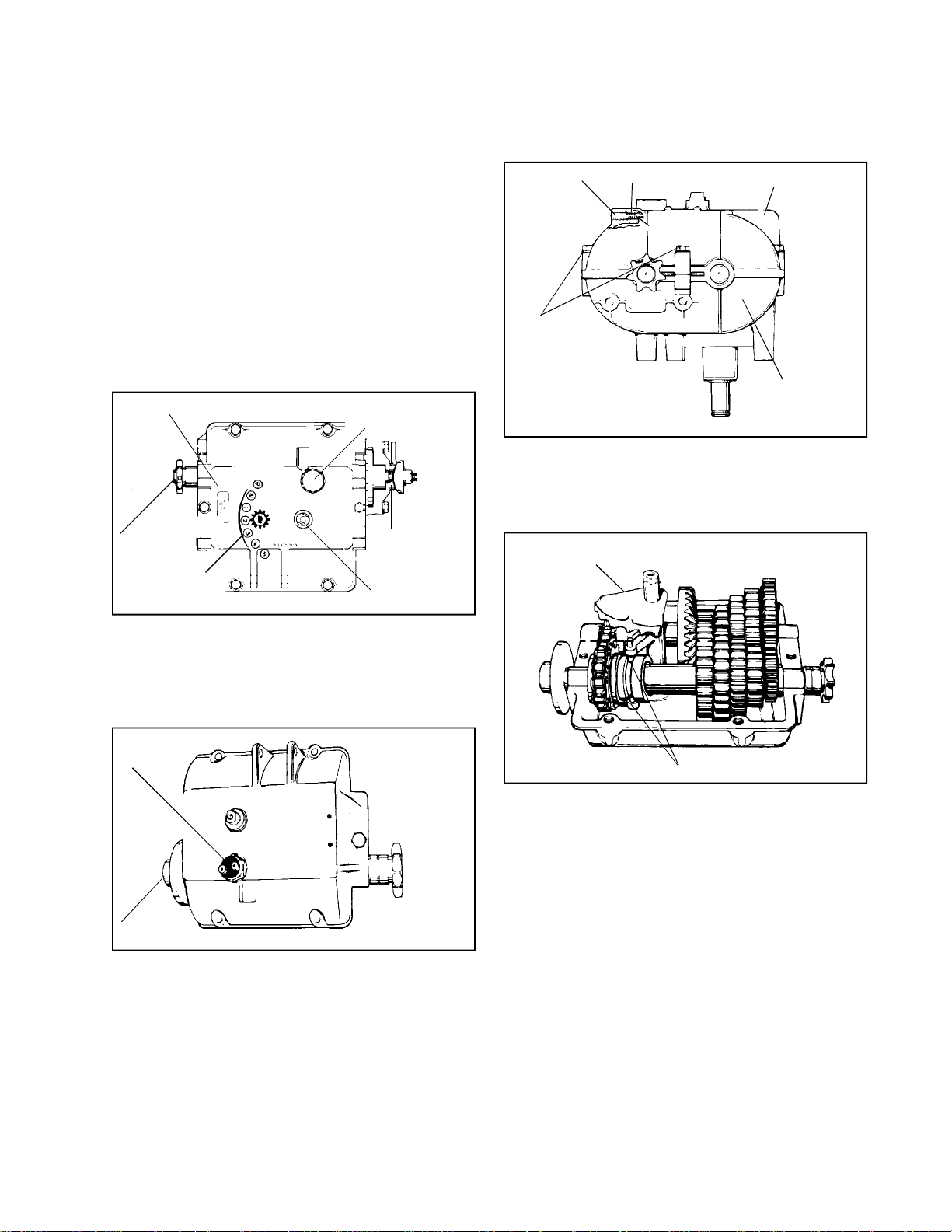
I.D. TAG
OUTPUT
SPROCKET
SHIFT PATTERN
OF ROTO-SHIFT
NEUTRAL START
PROVISION
DISC BRAKE
SHIFTER ROD
FOR IN-LINE SERIES TRANSMISSION
SETSCREW
CAP
SCREWS
SPRING
INDEX BALL
COVER
CASE
1. Remove setscrew, spring and index ball from
transmission cover.
2. Remove six cap screws that maintain cover
to case.
SHIFTER ASSEMBLY
SHIFTER FAN
SHIFTER ROD
The two speed unit is not covered here but can be
disassembled and reassembled using the same
information for the 700 described in this section.
Optional features include right or left hand output and
disk brake, for either in-line or “H” pattern unit.
NEUTRAL START
SWITCH
DISC BRAKE
OUTPUT
SPROCKET
NOTE: Due to the many variations of equipment braking
systems, adjustments and repair to these components
and linkages are not considered warranty.
If installed, (optional equipment), remove neutral start
switch.
B. DISASSEMBLY OF SHIFTER MECHANISM
SHIFTER PINS
3. Remove cover. Remove shifter assembly
(includes shafts, pins and fan from transmission
by lifting shaft out of case.
Clean outside surface of transmission. Position shift
lever in neutral position as indicated by the shift pattern.
13
Page 16
HUB MUST
Main Menu
Main Menu
FACE BEVEL
SPUR GEAR
REMOVE
BEARING
AND
SPROCKET
THRUST
WASHER
COUNTERSHAFT
ANGLE
SHAFT
TOGETHER
HERE
CHAIN
BEVEL
SPUR
GEAR
SHOULDER
COLLAR
SPUR GEARS
BUSHING
THICKEST
THRUST
WASHER
SNAP RING
"O" RING
SNAP RING
BEVEL
GEAR
THRUST
WASHER
NEEDLE
BEARINGS
THRUST
WASHER
INPUT
SHAFT
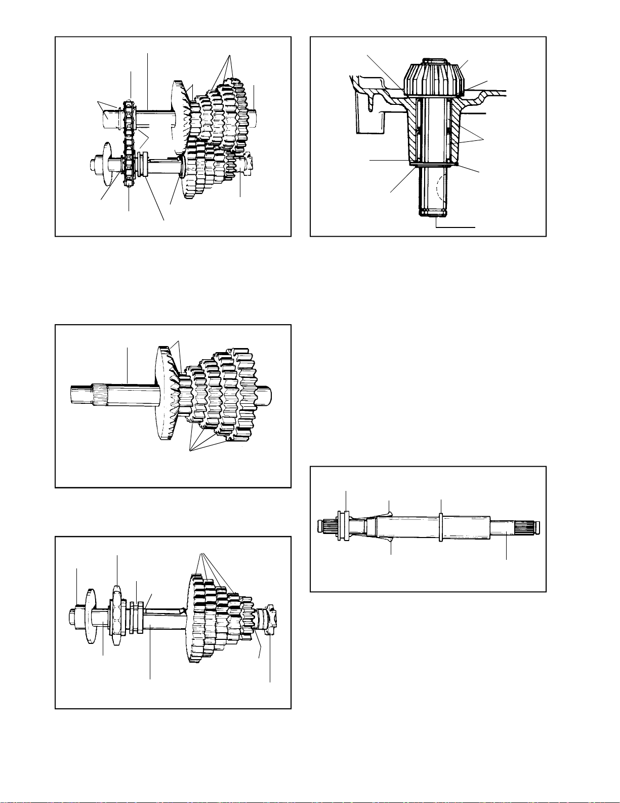
C. DISASSEMBLY OF UNIT
1. Remove gear and shaft assemblies from case
half of the transmission by lifting the two shafts
out of the bearing supports taking care not to
disturb drive chain relationship with hubs on
sprockets.
COUNTERSHAFT
BEVEL SPUR GEAR
SPUR GEARS
2. Remove bevel spur gear combination and spur
gears from the countershaft; these gears are
splined to the countershaft.
Input shaft removal for 700 series in-line
transmission.
4. Remove snap ring from input shaft; remove
bevel gear and pull shaft through case.
5. Input shaft needle bearings should be installed
flush to .005 below bearing bore surfaces from
inside and outside case.
D. INSPECTION AND REPAIR
Examine all parts after removing grease with cleaning
solvent. Replace damaged parts.
E. ASSEMBLY OF 700 SERIES IN-LINE
TRANSMISSION
1. Install and secure the input shaft and bevel
gear in the case. See Paragraphs 4 & 5 under
“Disassembly Instructions” and reverse the order.
COLLAR
KEY
SHOULDER
14
CHAIN SPROCKET
BRAKE
COLLAR
KEY
BUSHING
OUTPUT AND
BRAKE SHAFT
SHIFT SPUR GEARS
BUSHING
OUTPUT
SPROCKET
3. Remove the output sprocket and brake disc
from the output shaft. Remove the bushings,
shift spur gears, chain sprocket, collar and keys.
KEY
OUTPUT AND
BRAKE SHAFT
2. Install collar and keys on output shaft. Thick
side of collar MUST face shoulder on shaft.
NOTE: All Needle bearings are lubricated with
E.P. Grease. DO NOT USE BENTONITE on
needle bearings. For maximum gear train life
use only Bentonite grease on all shafts and
gears, Tecumseh part number 788067B.
Page 17
SHOULDER
Main Menu
Main Menu
COUNTERSHAFT
BEVEL SPUR GEAR
NEW
STYLE
CUT OUT
SIDE OF
GEAR MUST
FACE
OUTBOARD
END OF
SHAFT
FLAT SIDE OF
GEAR MUST
FACE
SHOULDER
ON SHAFT
EARLY
STYLE
THRUST
WASHER
(SEPARATES
GEAR FROM
BEARING)
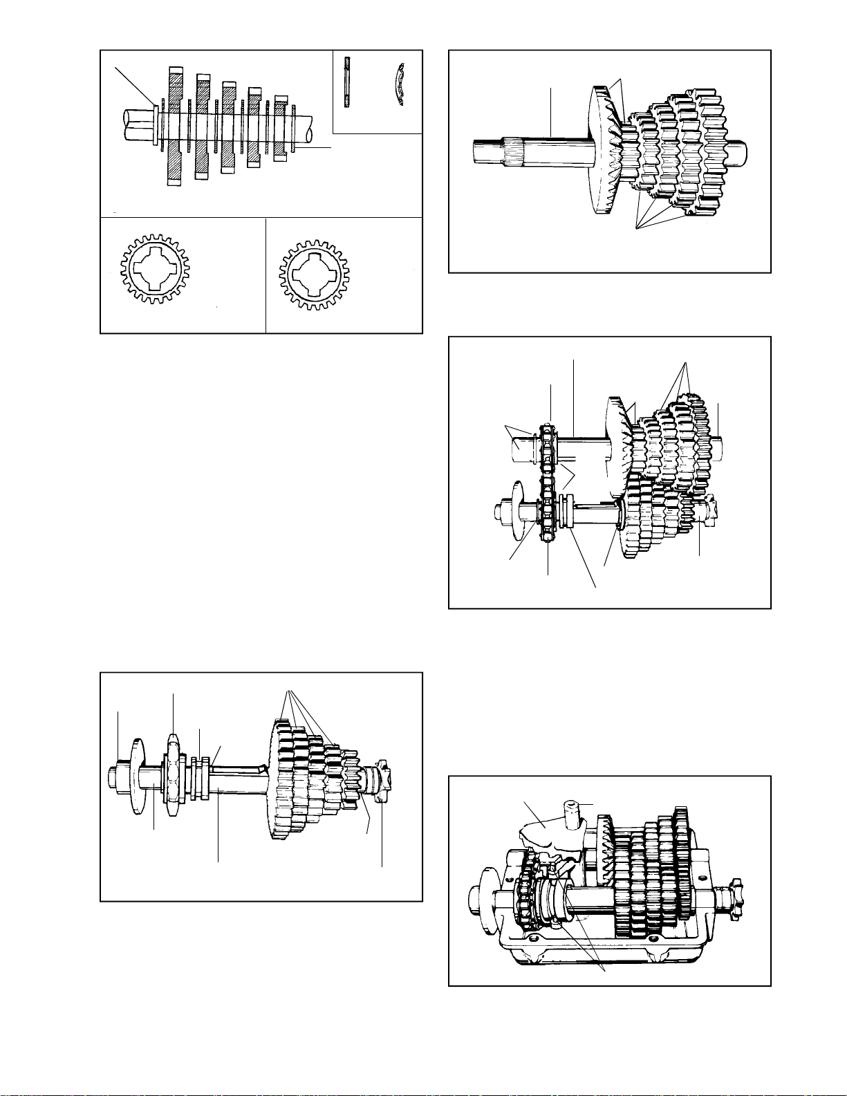
3. Install the thrust washers and shifting gears
onto the shifter/brake shaft. The number of gears
and/or spacers will be determined by the number
of speeds in the transmission.
WASHERS. A running change has been made
to the shifting washers. Many models have used
the thrust washer with a 45o chamfer on the
inside diameter. The latest style washer has a
curved or rounded side. The purpose of both
washers is to compress the shifting keys as
they slide into the gears. Therefore, the
chamfered or rounded side of these washers
must face the shoulder of the shaft or towards
the shifting keys. The washers are
interchangeable.
SHIFTING GEARS. The 2 sides of the shifting
gears are different. One side is flat and the
other side is cut out. The flat side of the gear
is placed onto the shaft towards the shoulder
of the shaft or towards the shifting keys.
CHAIN SPROCKET
BRAKE
COLLAR
KEY
SHIFT SPUR GEARS
SPUR GEARS
5. Install bevel spur gear and smallest to largest
spur gears to the splined end of the counter
shaft.
HUB MUST
FACE BEVEL
SPUR GEAR
REMOVE
BEARING
AND
SPROCKET
THRUST
WASHER
COUNTERSHAFT
ANGLE
SHAFT
TOGETHER
HERE
CHAIN
BEVEL
SPUR
GEAR
SHOULDER
COLLAR
SPUR GEARS
BUSHING
THICKEST
THRUST
WASHER
6. Install chain over two shafts registering chain
on output shaft sprocket and in-line with
serrations on countershaft. Be sure collar on
sprocket faces shifting keys and collar.
7. Install shaft assemblies into case utilizing piloting
locators on bearings to properly align notches
in case.
CAUTION: Be sure bearing locators are seated
in transmission case.
BUSHING
OUTPUT AND
BRAKE SHAFT
BUSHING
OUTPUT
SPROCKET
4. When correctly assembled the output shaft
should appear as shown.
SHIFTER ASSEMBLY
SHIFTER FAN
SHIFTER ROD
SHIFTER PINS
8. Install shifter assembly (shaft, pins and fan)
12 oz. Bentonite grease around gearing, and
reinstall cover on case. Torque cap screws 90110 in. lbs.
15
Page 18
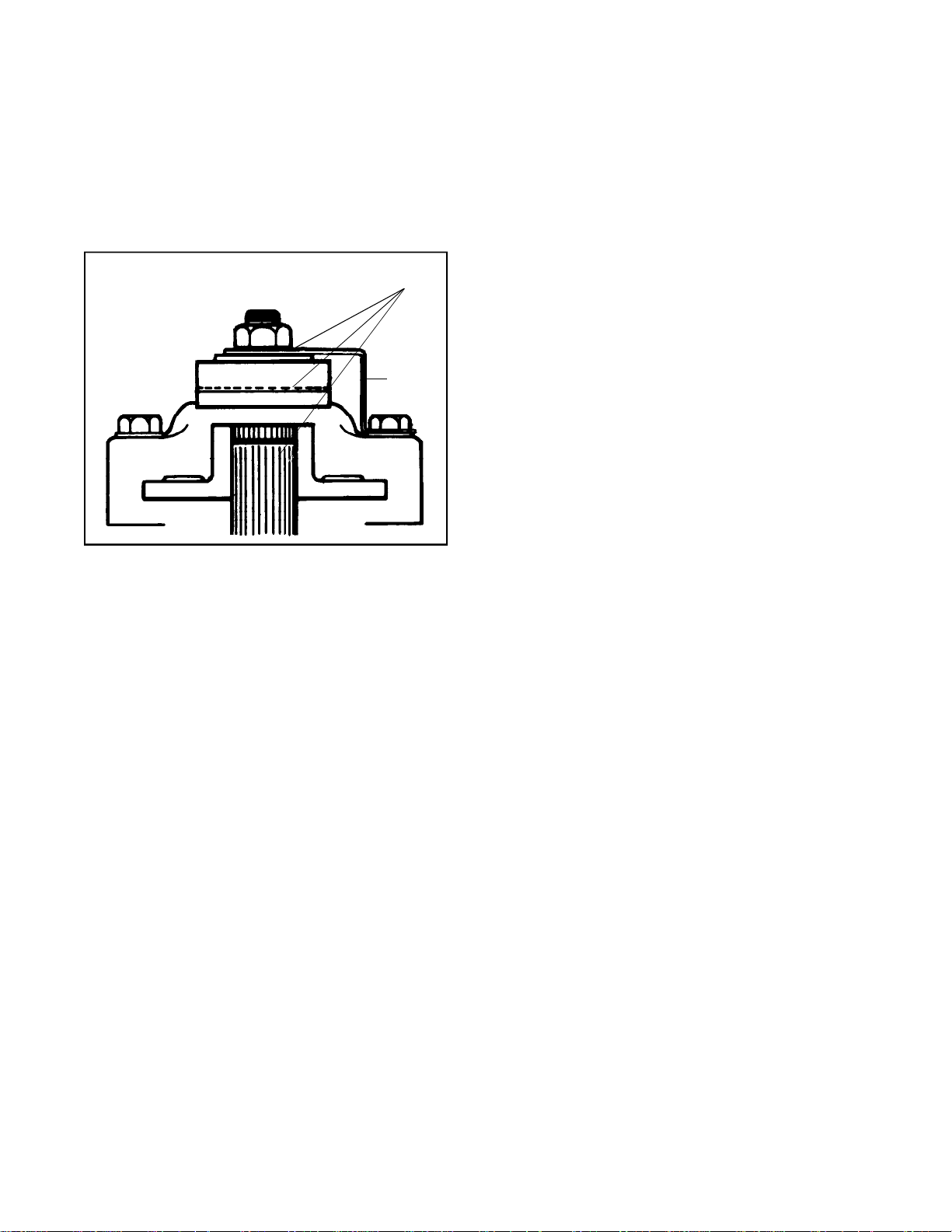
9. For “in-line transmission”, install index ball,
Main Menu
Main Menu
spring, and setscrew, in that order, into cover
and slowly tighten the screw from flush to two
turns below flush, depending on personal
preference.
10. Check for binding by turning input shaft. Install
transmission on equipment. Install brake and
linkage and adjust to disengage when clutch
is engaged. Consult equipment Owner’s Manual.
APPLY LUBRIPLATE
BRAKE
BRACKET
11. Apply a light film of lubriplate to the inside of
lever portion which contacts pins, also to outside
of lever which contacts flat washer and between
shaft O.D. and bore of brake disc. Brake pads
and brake disc must be free of grease and oil.
Brake and linkages may vary.
NOTE: If adjusted incorrectly, the brake will do one
of two things;
a. It will not brake (stop) the vehicle when
the brake is applied, or
b. If adjusted too tightly, a drag or continued
braking effect will be evident until the brake
wears out.
16
Page 19
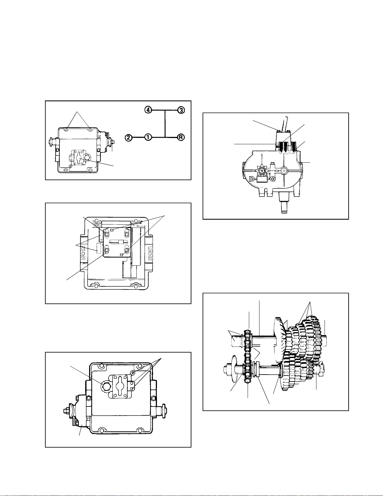
SECTION 2. 700H SERIES
Main Menu
Main Menu
CAUTION
TO AVOID PREMATURE TRANSMISSION FAILURE,
DECLUTCHING IS REQUIRED WHEN SHIFTING
FROM NEUTRAL TO FIRST OR REVERSE, FROM
ANY FORWARD TO REVERSE GEAR, FROM
REVERSE TO ANY FORWARD GEAR OR WHEN
OPERATING EQUIPMENT ON A HILL OR UNDER
HEAVY LOAD.
CAP SCREWS (6)
SHIFT PATTERN
DISC BRAKE
SHIFTER ROD
The “H” pattern transmission described here is a 4speed forward, 1 reverse unit.
TORQUE SCREWS
70-90 IN. LBS
SHIFTER
PLATES (2)
TABS IN
SLOTS
NOTE: Due to the many variations of equipment braking
systems, adjustments and repair to these components
and linkages are not considered warranty.
A. DISASSEMBLY OF SHIFTER MECHANISM
Clean outside of transmission. Position shift lever
in neutral position as indicated by the shift pattern.
FOR THE “H” SHIFT PATTERN 700 SERIES
TRANSMISSION.
HEX SCREWS (4)
SPRING
SETSCREW
INDEX BALL
HEX SCREWS
(6)
1. Remove shift lever by removing four hex screws
on shift lever cover.
2. With a 3/32 inch Allen wrench, remove screw,
spring and index ball in three places (balls will
roll out once spring is removed).
PLATE
The 700 series “H” pattern transmission gear
arrangement is the same as the in-line transmission
except for the shifting portion and an additional collar
on the out put and brake shaft and an additional spacer
on the countershaft and spacer on the output and
brakeshaft.
NEUTRAL START
SWITCH
DISC BRAKE
SETSCREW
If installed, (optional equipment), remove neutral start
switch.
3. Remove six cap screws that maintain cover
to case. Remove cover.
B. DISASSEMBLY OF UNIT
HUB MUST
FACE BEVEL
SPUR GEAR
REMOVE
BEARING
AND
SPROCKET
THRUST
WASHER
COUNTERSHAFT
ANGLE
SHAFT
TOGETHER
HERE
CHAIN
BEVEL
SPUR
GEAR
SHOULDER
COLLAR
SPUR GEARS
BUSHING
THICKEST
THRUST
WASHER
1. Remove gear and shaft assemblies from case
half of the transmission by lifting the two shafts
out of the bearing supports taking care not to
disturb drive chain relationship with sprockets.
2. Angle chain and sprocket ends of shaft toward
each other, removing the bearing and sprocket
from the countershaft. Note the collar on the
sprocket faces the bevel spur gear. Remove
chain.
17
Page 20
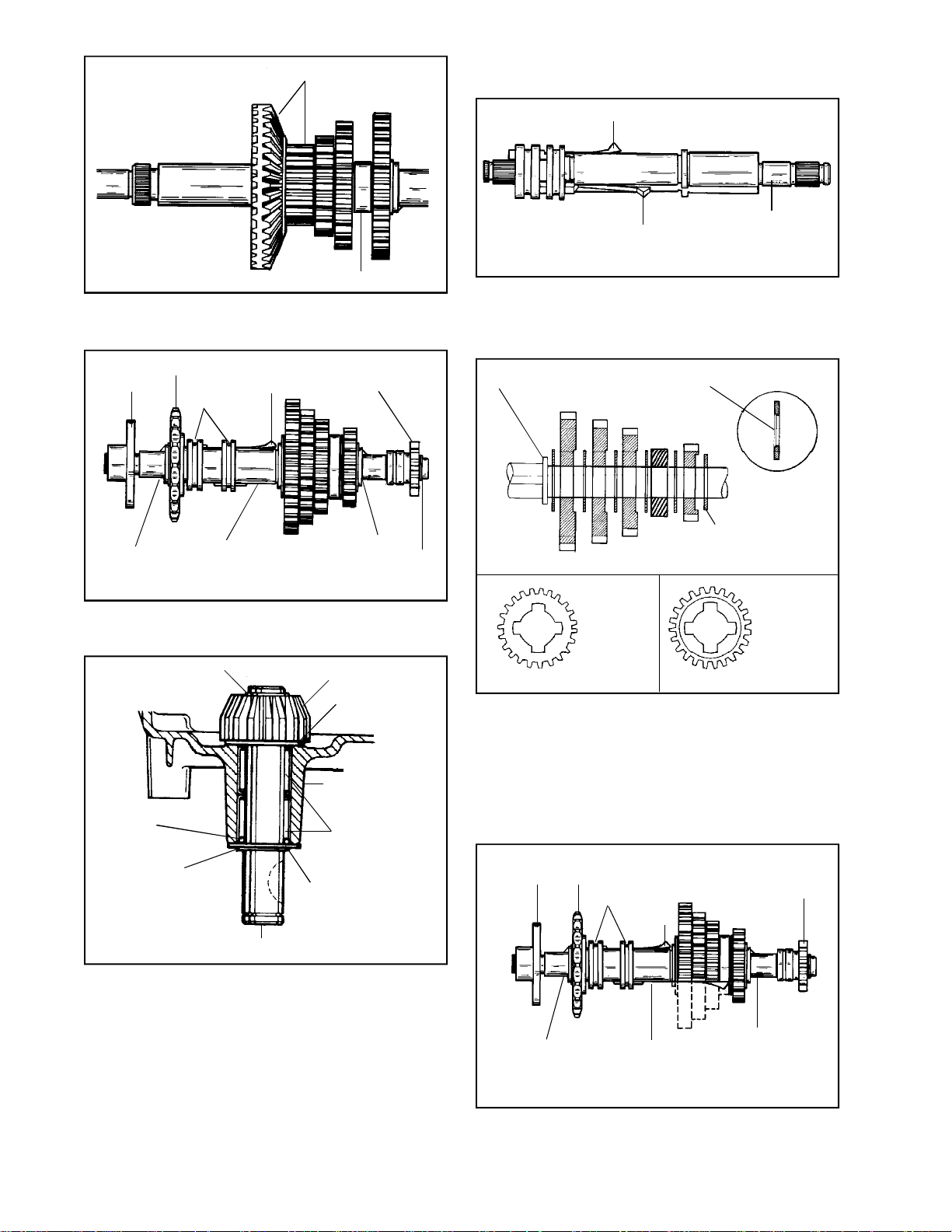
BEVEL SPUR GEAR
Main Menu
Main Menu
D. ASSEMBLY OF 700 SERIES “H” SHIFT
PATTERN.
KEY
SPACER
Disassembly of the 700 series “H” shift pattern
includes spacer.
BRAKE
DISC
BUSHING
CHAIN SPROCKET
KEY
COLLAR
OUTPUT AND
BRAKE SHAFT
OUTPUT
SPROCKET
BUSHING
Disassembly of the 700 series “H” shift pattern
includes a second collar and a spacer.
SNAP RING
BEVEL GEAR
SNAP
RING
KEY
OUTPUT AND
BRAKE SHAFT
Same as 700 series in-line except for additional
collar and spacer.
ASSEMBLY OF 700 SERIES “H” SHIFT PATTERN
SHOULER
FLAT SIDE
OF GEAR
MUST FACE
SHOULDER
ON SHAFT
450 CHAMFER
THRUST WASHER
(SEPARATES GEAR
FROM BEARING)
CUT OUT SIDE
OF GEAR
MUST FACE
OUTBOARD
END OF
SHAFT
THRUST WASHER
INSTALL BEARINGS FLUSH
TO .005 BELOW CASE
SURFACE
"O" RING
SNAP RING
INPUT SHAFT
NEEDLE
BEARINGS
THRUST WASHER
Input shaft removal same for 700 series inline and “H” shift pattern transmissions.
3. Remove snap ring from input shaft; remove
bevel gear and pull shaft through case.
4. Input shaft needle bearings should be installed
flush to .005 below bearing bore surfaces from
inside and outside case.
C. INSPECTION AND REPAIR
Examine all parts after removing grease with cleaning
solvent. Replace damaged parts.
18
Same as for 700 series in-line transmission except
for additional spacer.
NOTE: The thrust washer on the shift gear end of the
output shaft does not have a chamfer on the inside
diameter and must be positioned as shown. It is thicker
than the other thrust washers separating the gearworks
from the bearings.
BRAKE
DISC
BUSHING
CHAIN
SPROCKET
COLLAR
OUTPUT AND
BRAKE SHAFT
OUTPUT
SPROCKET
KEY
BUSHING
Correct assembly for 700 Model “H” shift pattern.
First, second and third gears have to be forced over
the key, when assembling.
Page 21
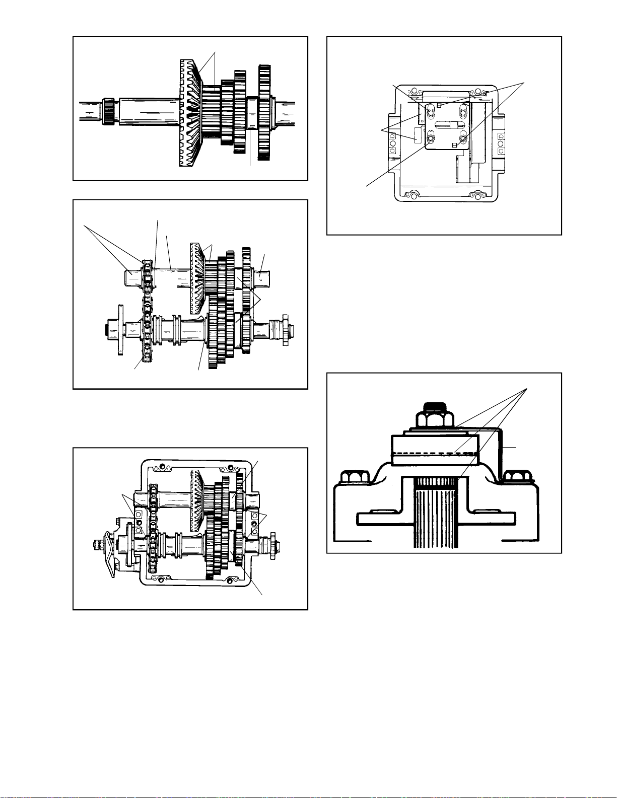
BEVEL SPUR GEAR
Main Menu
Main Menu
REMOVE BEARING
AND SPROCKET
COLLAR MUST FACE
BEVEL SPUR GEAR
COUNTERSHAFT
BEVEL SPUR GEAR
ANGLE
SHAFT
TOGETHER
HERE
SPACER
BUSHING
SPACER
TORQUE SCREWS
70-90 IN. LBS
SHIFTER
PLATES (2)
PLATE
TABS IN
SLOTS
Install shifter assembly, 12 oz. Bentonite grease around
gearing, and reinstall cover on case. Torque cap screws
90-110 in. lbs.
To put tension on the index ball, spring and set screw.
Tighten down to flush then two (2) turns in below flush.
Check for binding by turning input shaft. Install
transmission on equipment. Install brake and linkage
and adjust to disengage when clutch is engaged.
Consult equipment Owner’s Manual.
CHAIN
SHOULDER
With collar on countershaft sprocket facing the bevel
spur gear, install sprocket onto serration and install
chain. Install all (4) thrust washers, MUST be positioned
on the shifting gear of the output shaft.
SPACER
NOTCHES
NOTCHES
SPACER
Install bronze bearings and disc and sprocket. Install
shaft assemblies into case utilizing piloting locators
on bearings to properly align notches in case. CAUTION:
Be sure bearing locators are seated in transmission
case.
APPLY LUBRIPLATE
BRAKE
BRACKET
Apply a light film of lubriplate to the inside of lever
portion which contacts pins, also to outside of lever
which contacts flat washer and between shaft O.D.
and bore of brake disc. Brake pads and brake disc
must be free of grease and oil.
Brake and linkages may vary.
NOTE: If adjusted incorrectly, the brake will do one of
two things;
a. It will not brake (stop) the vehicle when the
brake is applied, or
b. If adjusted too tightly, a drag or continued braking
effect will be evident until the brake wears out.
19
Page 22
SECTION 3. 2800 SERIES TRANSMISSION
Main Menu
Main Menu
A. GENERAL
INPUT SHAFT
OUTPUT
SHAFT
MOUNTING
HOLES
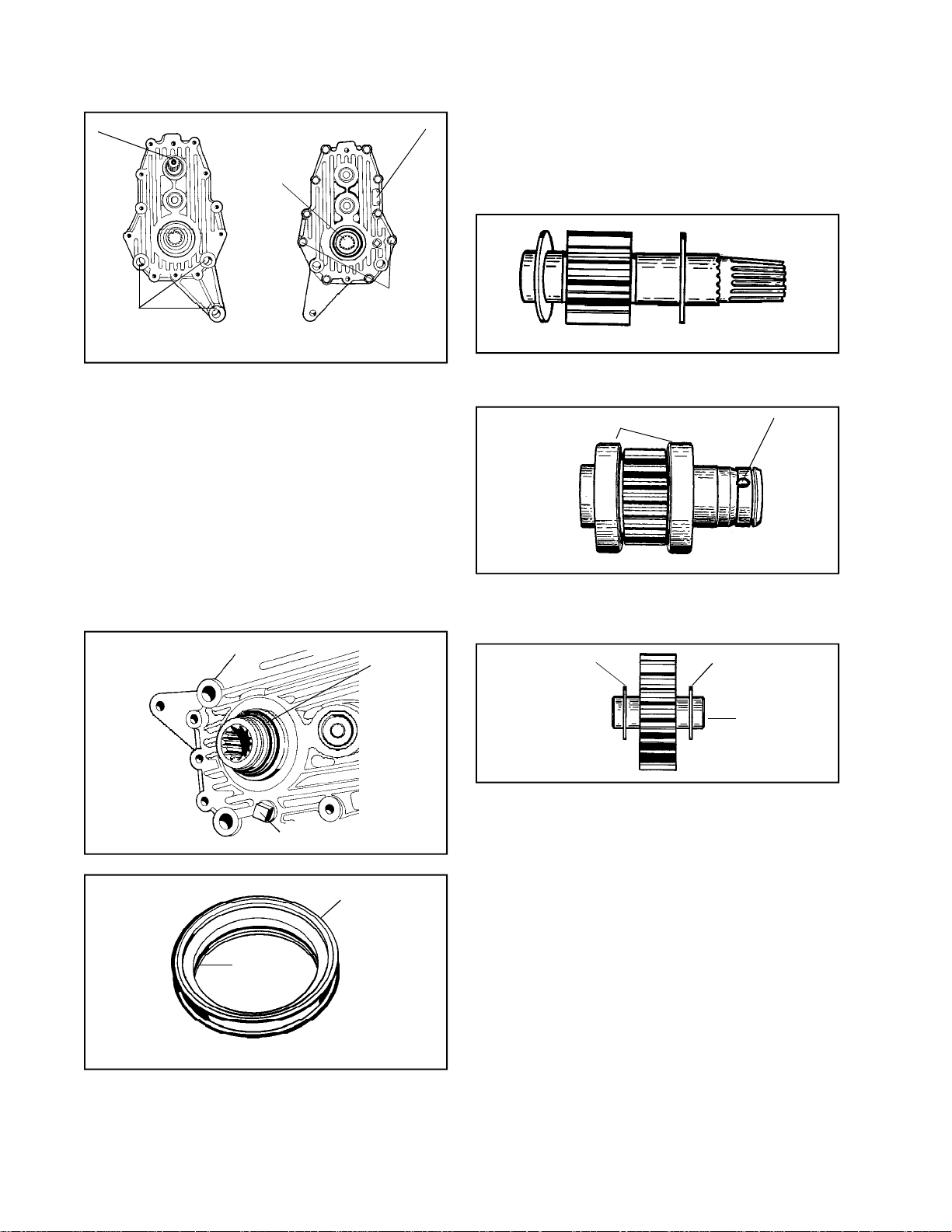
The Model 2800 series transmission is the first of
its kind produced by Peerless. It’s known as a P.T.O.
(Power Take Off) unit. This unit mounts on the back
side of the Model 2600 series transaxle. Some
O.E.M.’s are using this unit to run auxiliary
attachments such as large tillers, mower decks,
or any attachments that need power to make them
operate.
ID TAG
LONGER
BOLTS FOR
SHIELD
MOUNTING
4. Using a punch, remove dowel pins that align
case & cover together.
5. Remove the cap screws that maintain the cover
to case. Remove cover.
6. Remove gasket and discard. Inspect gears and
bearing surfaces.
INPUT SHAFT
7. Remove the input shaft and two washers. The
input shaft and gear are one piece.
BEARINGS
HOLE
FOR
STEEL
BALLS
B. DISASSEMBLY
1. Clean outside surface of transmission.
2. To remove small outer snap ring, located on
the output shaft, use a small ice pick or similar
tool.
COLLAR
OIL LEVEL PLUG
COLLAR
SNAP
RING
OUTPUT SHAFT
8. Remove output shaft. Output shaft bearings
can be removed by using a bearing splitter and
puller.
WASHER
WASHER
IDLER SHAFT
9. Remove the idler shaft and two washers.
C. INSPECTION AND REPAIR
1. Inspect both the case and cover bearing
surfaces. For bearing maintenance, refer to
Chapter 11. Examine all parts after removing
oil with cleaning solvent. Check for any wear
and replace any damaged parts.
D. REASSEMBLY
1. Press new bearings onto output shaft.
20
2. Install the two large oil seals for output shaft
in the case and cover first.
3. The collar has to be removed next. Place a
jaw type puller around the collar and pull off.
This will expose 3 steel balls equally spaced
in holes around output shaft. There will be a
snap ring in the inside of the collar. After the
collar is pulled off discard snap ring.
Page 23
WASHER
Main Menu
Main Menu
WASHER
IDLER SHAFT
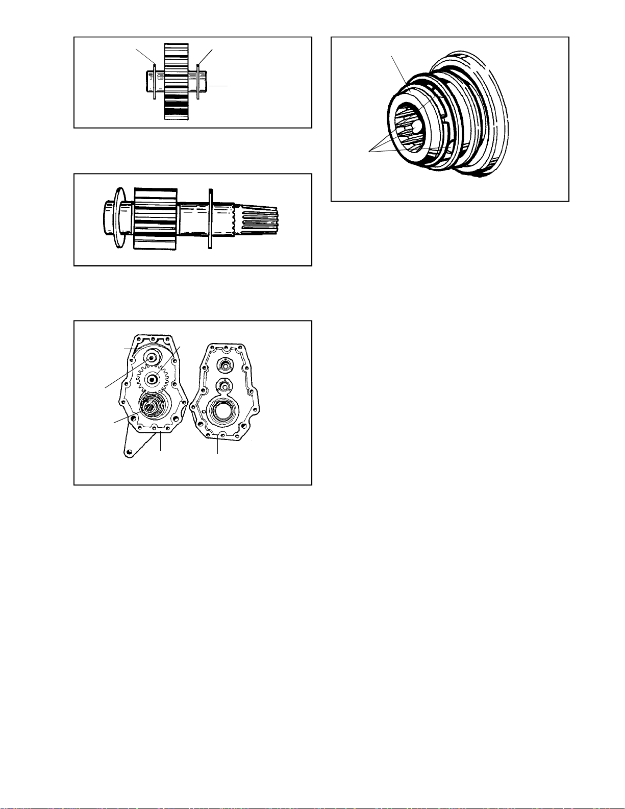
3. Place idler gear into case with washers on both
sides along with output shaft at the same time.
SNAP RING
BALLS
9. Install 3 steel balls in holes with a little grease
to hold them in place.
10. Place larger ring into collar and force over output
shaft.
4. Place one input shaft washer on bearing boss
next to idler gear. Place proper seal protector
for input shaft in seal and insert shaft and second
washer.
CASE
IDLER
SHAFT
COVER
OIL
DEFELCTOR
INPUT
SHAFT
OUTPUT
SHAFT
5. Before closing case and cover together, inspect
to make sure all parts are present. Now place
new gasket between case and cover.
6. NOTE: Make sure oil deflector is in place before
case/cover is put together.
7. Put case and cover together and before installing
bolts, push dowel pins in place so that both
halves line up.
11. Place smaller ring over output shaft after collar
is in place.
12. Fill with proper lubricant according to O.E.M.
specs.
13. If everything is properly installed, unit should
spin freely.
8. Tighten and torque bolts to 15 to 18 ft. lbs.
21
Page 24
CHAPTER 3. TRANSAXLES
Main Menu
Main Menu
SECTION 1. 600 SERIES
CAUTION
TO AVOID PREMATURE TRANSAXLE FAILURE,
DECLUTCHING IS REQUIRED WHEN SHIFTING
FROM NEUTRAL TO FIRST OR REVERSE, FROM
ANY FORWARD TO REVERSE GEAR, FROM
REVERSE TO ANY FORWARD GEAR OR WHEN
OPERATING EQUIPMENT ON A HILL OR UNDER
HEAVY LOAD.
A. GENERAL
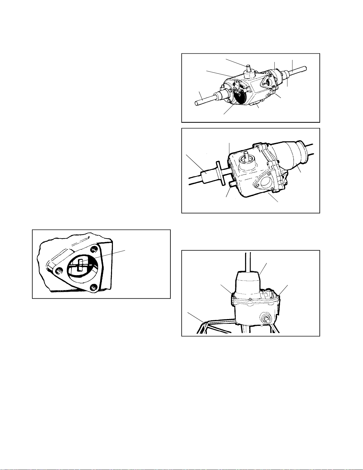
There are two (2) types of 600 series transaxles.
One is the 600 standard series transaxle. The other
is the 601-001, 002, 003 etc. slow speed series
transaxle. This first section will deal with the standard
600 series. Please refer to the next section on the
differences of the 601 slow speed transaxle.
The 600 Series transaxle has an aluminum case
and cover. The input shaft is on the top of the case.
Some 600 series transaxles are equipped with
optional disc brakes. Due to the many variations
of equipment braking systems, adjustments and
repair to these components and linkage are not
considered warranty.
B. TRANSAXLE DISASSEMBLY
NEUTRAL
POSITION
INPUT SHAFT
CASE
RIGHT
AXLE
DISC BRAKE
AXLE HOUSING
BRAKE SHAFT
COVER
SHIFT LEVER
HOUSING
IDENTIFICATION
PLATE
LEFT AXLE
AXLE HOUSING
CENTER PLATE
COVER
CASE
2. After removing axle housings, place the unit
in a receptacle, bench or clamp the transaxle
in a soft jaw vise. Position the transaxle so
that the socket head cap screws are facing
up.
COVER
1. Clean the outside surface of the transaxle, away
from the area where disassembly will take place.
Position shift lever in neutral position to help
disassembly. Remove screws (3) holding shift
lever. Remove all keys from keyways, remove
all burrs and dirt from shafts. On hardened
shafts, use a stone to remove burrs. All seals
should be replaced whenever a shaft is pulled
through a seal. Always use a new gasket
whenever the gasket surfaces have been
separated.
DOWEL
DOWEL PIN
BENCH RECEPTACLE
PIN
3. Remove the socket head cap screws holding
the case and cover together. Drive out the dowel
pins used for alignment of the case and cover.
22
Page 25
DIFFERENTIAL
Main Menu
Main Menu
ASSEMBLY
SEAL PROTECTOR
COVER
CENTER
PLATE
ASSY.
SHIFTER GEARS
SHAFT
REVERSE IDLER
THREE
GEAR
CLUSTER
SHIFTER
ASSEMBLY
SHIFTER
RODS
INPUT
SHAFT
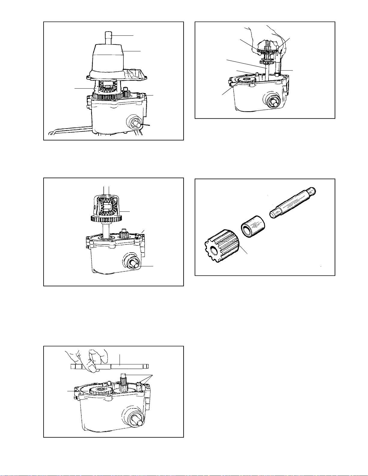
4. Use a seal protector on axle shaft and lift off
transaxle cover assembly. Because this seal
is a single lip type, it may be reused, if care is
taken to see that it isn’t cut or scratched. Discard
gasket.
DIFFERENTIAL
ASSEMBLY
SCREW
FASTENERS
INPUT
SHAFT
5. To remove differential assembly, it may be
necessary to replace two or three screws to
hold center plate assembly down. Pull assembly
straight up. If tight, tap on lower axle with soft
mallet. CAUTION: DO NOT USE STEEL
HAMMER. Refer to the chapter on differential
assembly service. Remove gear on top of shifter
shaft.
7. Remove complete shifter assembly by grasping
shifting gears, shaft and both shifter rods as a
unit.
NOTE: Examine assembly carefully; if no
service is required, retain assembly as a unit
for easy reassembly. If service is necessary
refer to the Chapter on shifting assemblies.
BEVELED EDGE
8. Remove reverse idler shaft, spacer and gear.
9. Remove cluster gear sub assembly and thrust
washer.
CENTER PLATE ASSEMBLY
THREE
GEAR
CLUSTER
SHIFTER
ASSY.
6. Remove temporary holding screws, if used and
lift off center plate assembly. Discard gasket.
23
Page 26
SHORT KEYWAY
Main Menu
Main Menu
BEVEL
LONGER KEYWAY
INPUT SHAFT
SEAL
BEVEL
LARGE
GEAR
SMALL
GEAR
BEVELED
EDGE
LONG
SPACER
SLEEVE
MEDIUM
GEAR
BEVELED
EDGE
MEDIUM
GEAR
LARGE GEAR
SLEEVE
SHORT
10. Cluster Gear Sub-Assembly
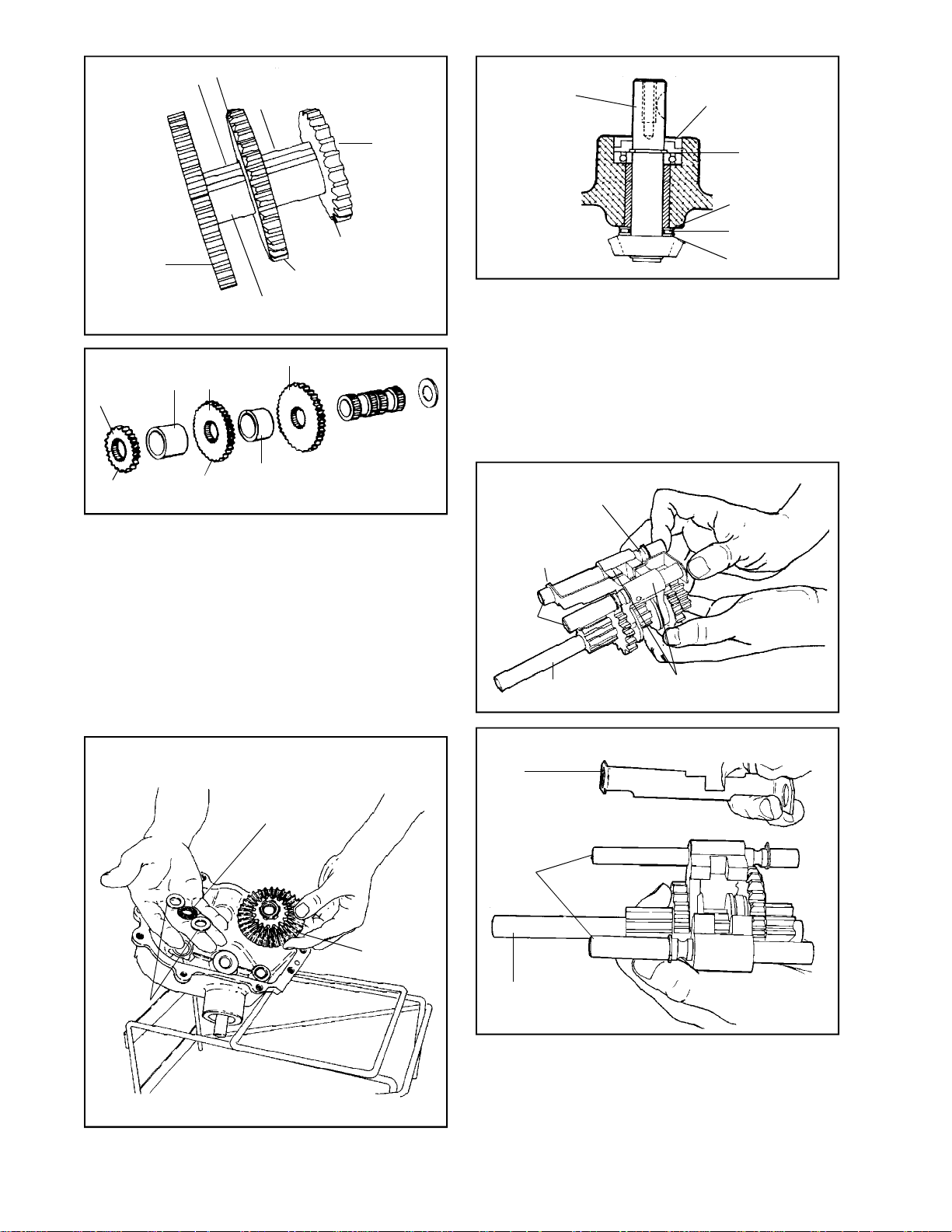
a. The cluster gear can be disassembled. All
worn gears are replaceable if damaged or
worn. Preferably use a press to drive the
shaft squarely.
b. The small and middle gear bevel faces
down, there is no beveled edge on large
gear. Shorter section between middle and
large gear.
c. Key edge ends must align with shaft ends.
SMALL
GEAR
OLD STYLE
NEW STYLE
SNAP RING
THRUST WASHER
BEARING
THRUST WASHER
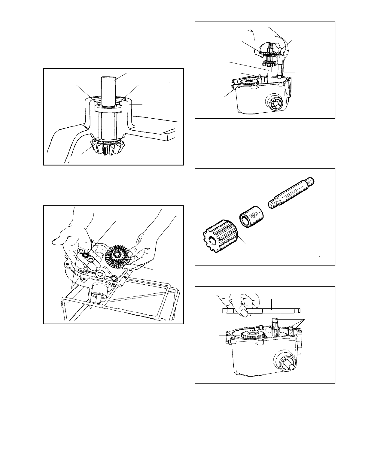
12. Remove input shaft oil seal to allow access to
snap ring. Remove snap ring and input shaft
will slide out. A removed seal must be replaced
by a new seal.
NOTE: One model (612) has a sealed ball bearing
instead of an oil seal. To remove this unit,
remove snap ring inside the case and drive
out. On model 612-A, remove the oil seal in
the normal manner.
SNAP RING RETAINER
SHIFTER
STOP
SHIFTER
RODS
BRAKE SHAFT
SHIFTER FORKS
(IN NEUTRAL POSITION)
THRUST
BEARING
IDLER
GEAR
THRUST
WASHERS
11. Remove the idler gear, thrust washers and thrust
bearing.
24
SHIFTER
STOP
SHIFTER
RODS
BRAKE
SHAFT
SHIFTING ASSEMBLY
The shifting assembly is usually removed from
and installed into the transaxle as a unit. The
assembly is removed and replaced by grasping
the shifting rods firmly. This will cause the binding
necessary to hold the assembly together. Before
removal or installation of the shifting assembly,
Page 27
notches in the shifter forks should be aligned
Main Menu
Main Menu
with notches in the shifter stop. This indicates
that shifting assembly is in a neutral position.
The shifter stop must be so positioned so that
the notch aligns with notches in shifter forks.
For service of the shifting assembly, refer to
Chapter 10.
SNAP RING
RETAINER
BALL
BEARING
INPUT SHAFT
SEAL
CASE
SHIFTER
SHIFTER GEARS
SHAFT
REVERSE IDLER
THREE
THREE
GEAR
GEAR
CLUSTER
CLUSTER
ASSEMBLY
SHIFTER
RODS
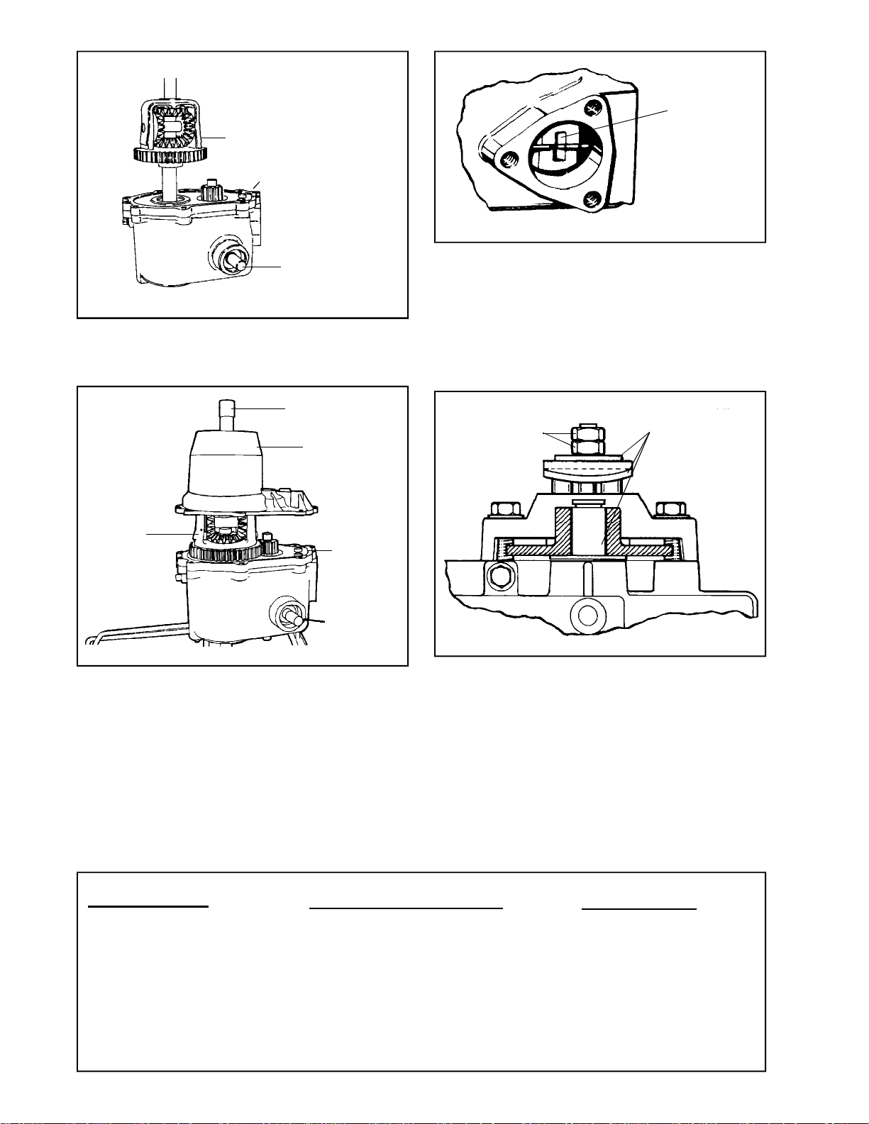
c. Insert the washer and then the three gear
cluster assembly. Making sure that the
bevels on the two shifting gears are facing
down.
BEARING
13. Transaxle Assembly
a. Install new seal thrust washers and bearing
on input shaft. Note sequence, and install
into case, using seal protector.
THRUST
BEARING
THRUST
WASHERS
b. Set case assembly open side up. Insert
the idler gear assembly, thrust washers and
bearing. Note sequence of washer and
bearings from case, thick washer, thrust
bearing thin washer, idler gear.
IDLER
GEAR
d. Insert shifter assembly. Check that rods
are seated properly.
BEVELED EDGE
e. Install reverse idler. Make sure beveled edge
is up. Spacer on top of gear.
CENTER PLATE ASSEMBLY
THREE
GEAR
CLUSTER
SHIFTER
ASSY.
CAUTION: Make sure that bearing and thrust
washers remain in place while assembling
idler gear, shifter and brake shaft.
f. Place new gasket on case and install center
plate.
25
Page 28
DIFFERENTIAL
Main Menu
Main Menu
ASSEMBLY
SCREW
FASTENERS
NEUTRAL
POSITION
INPUT
SHAFT
g. Place new gasket on center plate and install
differential assembly, longer axle in down
position. Be sure gear on shifter shaft is
on shaft.
SEAL PROTECTOR
COVER
DIFFERENTIAL
ASSEMBLY
h. Install gear case dowel pins. Leave dowel
pins slightly exposed on top to locate cover
assembly. Install cover assembly and
Torque the cap screws to 7-9 ft. lbs. or 84108 in. lbs.
i. If unit needs bearings or bushings installed,
consult the Chapter for bearing and bushing
service for proper procedures.
CENTER
PLATE
ASSY.
INPUT
SHAFT
k. Inspection Note: For a neutral position, shift
notches in forks and notch in stop must
be aligned and centrally located.
14. Brake Lever Assembly
The brake lever type is determined by the original
equipment manufacturer’s selection of this option.
JAM NUTS
APPLY LUBRIPLATE
When assembling, apply a light film of lubriplate
to the inside lever portion which contacts the
pins, also to outside of lever, which contacts
flat washer, and between shaft O.D. and bore
of brake disc. Brake pads and brake disc must
be free of grease and oil.
NOTE: To secure brake lever, hold bottom nut
and torque top nut to 100 in. lbs.
26
j. Install axle supports and fill with S.A.E.
80W90 part number 730229A gear lube. Fill
through shifter housing.
600 SERIES BEARING TOOLS
PART LOCATION TOOL REMOVE & REPLACE BEARING SIZER
Brake Shaft 670210 (27 needles)
Axle 670204
*Input Shaft *670207A
Center Plate 670205
Brake Shaft 670213 (30 needles)
Differential 670204
Cluster Gear 670204
Idler Gear 670210
Axle Housing 670204
Reverse Idler
*Bearing must be flush with top of case. Secure with Loctite.
Page 29
SECTION 2. 601 SLOW SPEED SERIES
Main Menu
Main Menu
GENERAL
A. The outside appearance is exactly the same as
the 600 Standard. The following is just the difference
between the two series. Everything else is exactly
the same.
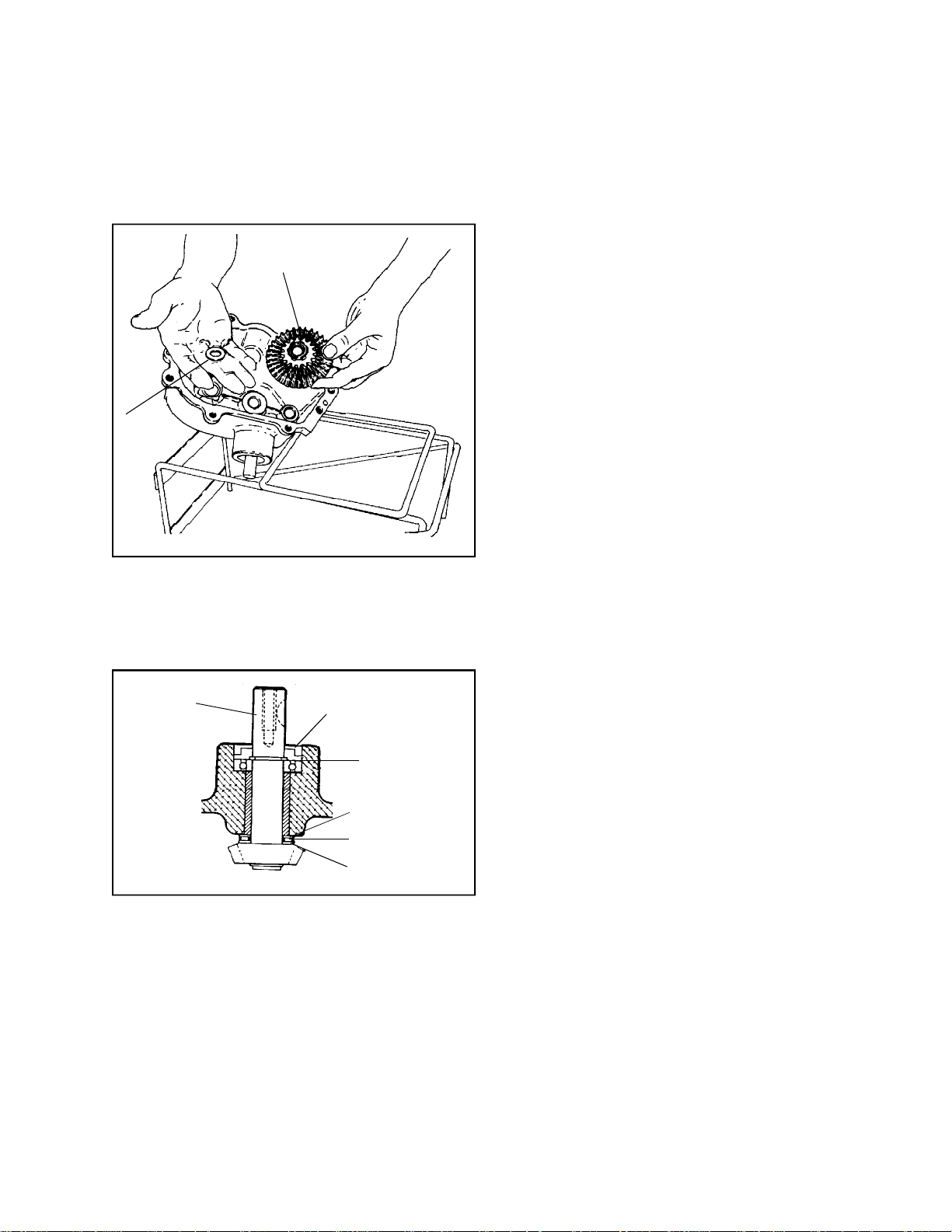
IDLER GEAR
THRUST
WASHER
1. Underneath the idler gear is one (1) washer in
stead of a thrust bearing and two (2) thrust
washers.
2. The idler gear is different than the standard.
INPUT SHAFT
SEAL
SNAP RING
THRUST WASHER
BEARING
THRUST WASHER
3. The input shaft has one (1) thrust washer only,
instead of a thrust bearing and two (2) thrust
washers.
4. The input shaft and bevel gear are also different
than on the standard 600 transaxle.
Everything else is the same.
27
Page 30
SECTION 3. 800/801 SERIES
Main Menu
Main Menu
CAUTION
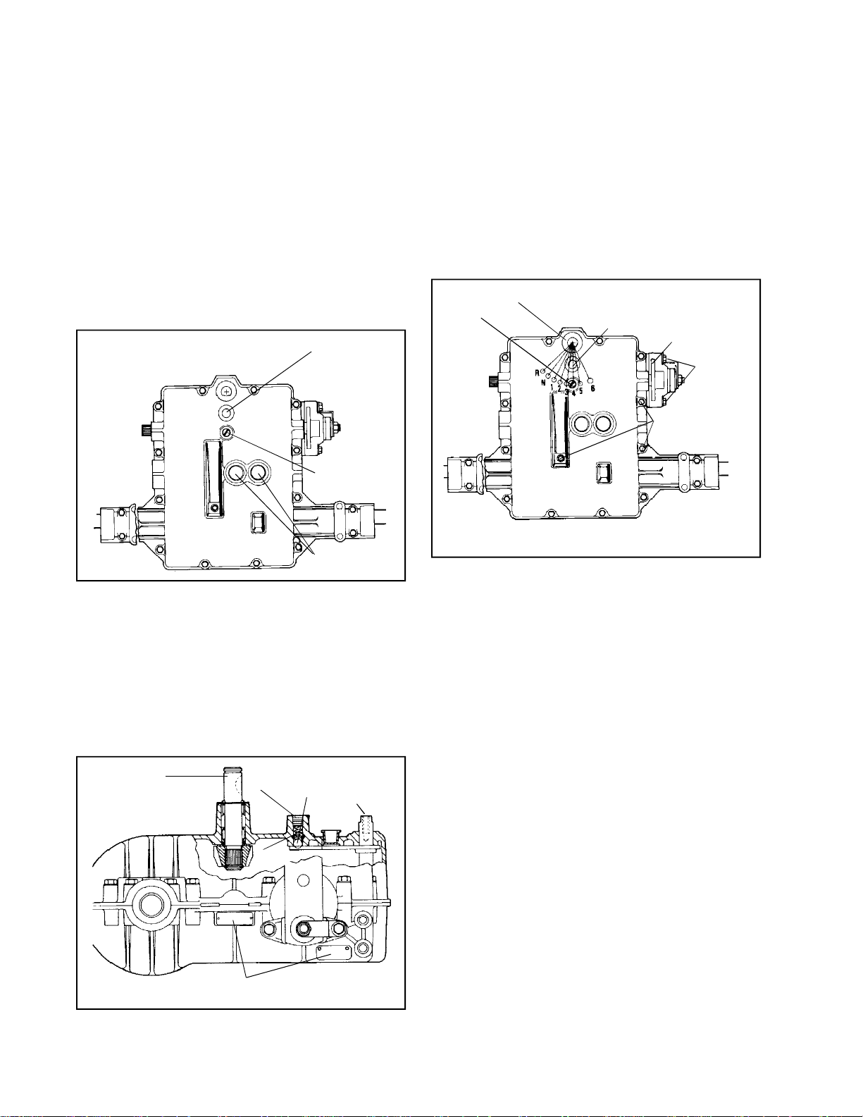
TO AVOID PREMATURE TRANSAXLE FAILURE,
DECLUTCHING IS REQUIRED WHEN SHIFTING
FROM NEUTRAL TO FIRST OR REVERSE, FROM
ANY FORWARD TO REVERSE GEAR, FROM
REVERSE TO ANY FORWARD GEAR OR WHEN
OPERATING EQUIPMENT ON A HILL OR UNDER
HEAVY LOAD.
NOTE: Due to the many variations of equipment braking
systems, adjustments and repair to these components
and linkages are not considered warranty. The brake
may be either a left-hand or right-hand per the O.E.M.
option.
NEUTRAL
START SWITCH
(OPTIONAL)
SETSCREW
C. PRE-DISASSEMBLY
1. Clean outside surface of transaxle.
2. Position shift lever in neutral position as
indicated by the shift pattern. Remove Allen
head screw, washer(s), and the shift lever.
3. If installed, (O.E.M. Option) remove neutral start
switch.
4. Remove setscrew, spring and index ball.
ALLENHEAD
SCREW
SHIFT ROD
NEUTRAL
START SWITCH
(OPTIONAL)
DISC BRAKE
(LEFT OR
RIGHT HAND
OPTIONAL)
BRAKE
BRACKET
SCREWS
COVER CASE HEX
SCREWS (17)
INPUT
(O.E.M. OPTION)
A. GENERAL
The 800/801 series transaxle is basically a combination
of the 700 series transmission with a 600 series
transaxle differential. The position of the input shaft
varies with a particular model. Because of the option
of input shaft and gear positioning on either side of
the bevel gear, the axle output will vary. The model
described in this section is a five speed forward, single
reverse. The input shaft for the model described in
this section is located to the left of the bevel gear.
INPUT SHAFT
SET
SCREW
SPRING
INDEX
BALL
FAN
SHAFT
ROD
D. DISASSEMBLY
1. Remove Hex screws that hold cover to case.
2. Push shift lever rod in while pulling cover off
of case. Shifting assembly may temporarily
remain in case. Remove cover.
NOTE: Remove grease from the unit as parts
are removed.
3. Remove two brake bracket screws, and remove
brake assembly.
NOTE: Prior to removal of gear shaft assemblies
from the case, the shifter fan may be removed.
It will be difficult to keep parts from falling off
the assemblies. Note position of parts before
removal.
B. IDENTIFICATION
The unit contains an aluminum tag at location A or B
showing the model number.
28
IDENTIFICATION TAG
Page 31
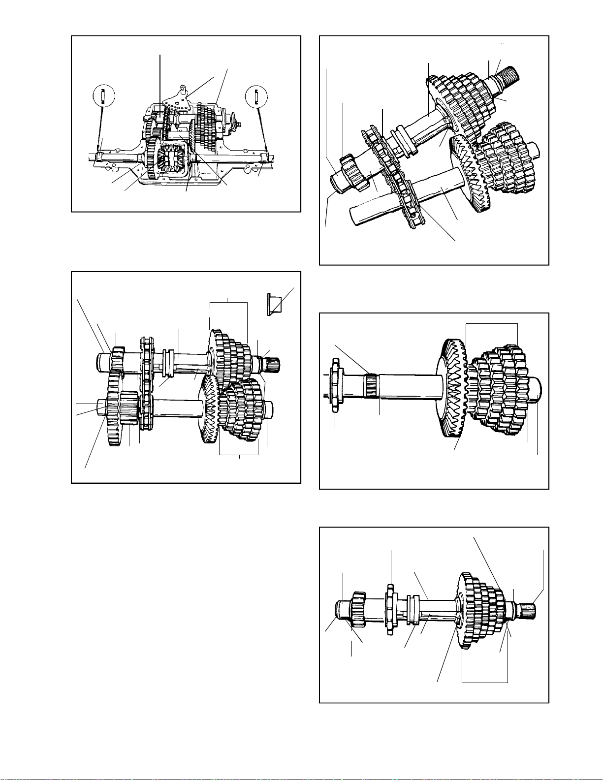
SHIFTER/BRAKE SHAFT
Main Menu
Main Menu
OIL SEAL
BEARING
SHIFTER FAN
CASE
HALF
OIL SEAL
FLANGED
BUSHING
SPUR
GEAR
SHIFTER/BRAKE
SHAFT
SPROCKET
COLLAR
SHIFT
WASHER
FLANGED
BUSHING
SQUARE CUT
"O" RING
THRUST
WASHER
FLANGED
BUSHING
DIFFERENTIAL
FLANGED
BUSHING
COUNTERSHAFT
BEARING
RETAINER
ASSEMBLY
4. Remove gear and shaft assemblies from case
half by lifting the two shafts out of the bearing
supports taking care not to disturb drive chain
relationship with hubs on sprockets.
FLANGED
BUSHING
THRUST
WASHER
NEEDLE
BEARING
(CLOSED
END) OR
BALL
BEARING
OUTPUT
GEAR
OUTPUT
PINION
FLAT WASHER
SPUR GEAR
SPACER
FLAT WASHER
(SQUARE CUT SEAL
IN EACH END OF
OUTPUT PINIOIN)
SHIFTER GEARS
SHIFTER/BRAKE
SHAFT
KEY
COLLAR
SPUR
GEARS
"V" NOTCH
SQUARE CUT
FLANGED
BUSHING
"O" RING
THRUST
WASHER
FLANGED
BUSHING
SPACER
SQUARE CUT
"O" RING
COUNTERSHAFT
SPROCKET
COLLAR
6. Angle the shifter/brake shaft and countershaft
chain sprocket ends toward each other. Note
the collar on the sprockets face the bevel gear.
Remove chain.
SPUR GEARS
SPLINE FOR CHAIN
SPROCKET GEAR
COUNTERSHAFT
SPROCKET
BEVEL GEAR
THRUST WASHER
FLANGED BUSHING
NOTE: Before disassembly, observe how “V”
notches on the flanged bushings fit into recess
“V” of case.
NOTE: The square cut black rubber “O” ring,
acts as a lubrication seal.
5. Remove the needle bearing (closed end) flat
washers (2), output gear and output pinion, and
3 square cut seals from the countershaft. (2
seals in output pinion 1 in needle bearing cap).
“O” rings on countershaft are larger than those
on brake shaft ends. Always replace with new
seals whenever removed.
7. Remove the sprocket, bevel gear, spur gears,
thrust washer, and flanged bushing. The spur
gears are splined to the countershaft.
FLANGED
BUSHING
SQUARE
CUT "O"
RING
"V" NOTCH
THRUST
WASHER
FLANGED BUSHING
SPROCKET
SHIFTER/BRAKE
SHAFT
KEY
SHIFT
COLLAR
SHIFT
WASHER
"V" NOTCH
SHIFTER GEARS
SPLINE FOR
DISC BRAKE
SQUARE
CUT "O"
RING
THRUST
WASHER
(NO
CHAMFER)
8. Remove the square cut seals (2) and flanged
bushings (2), thrust washers (2) on shaft ends,
spur gear, spacer, sprocket, shift collar with
keys, thrust washers and shifter gears.
29
Page 32
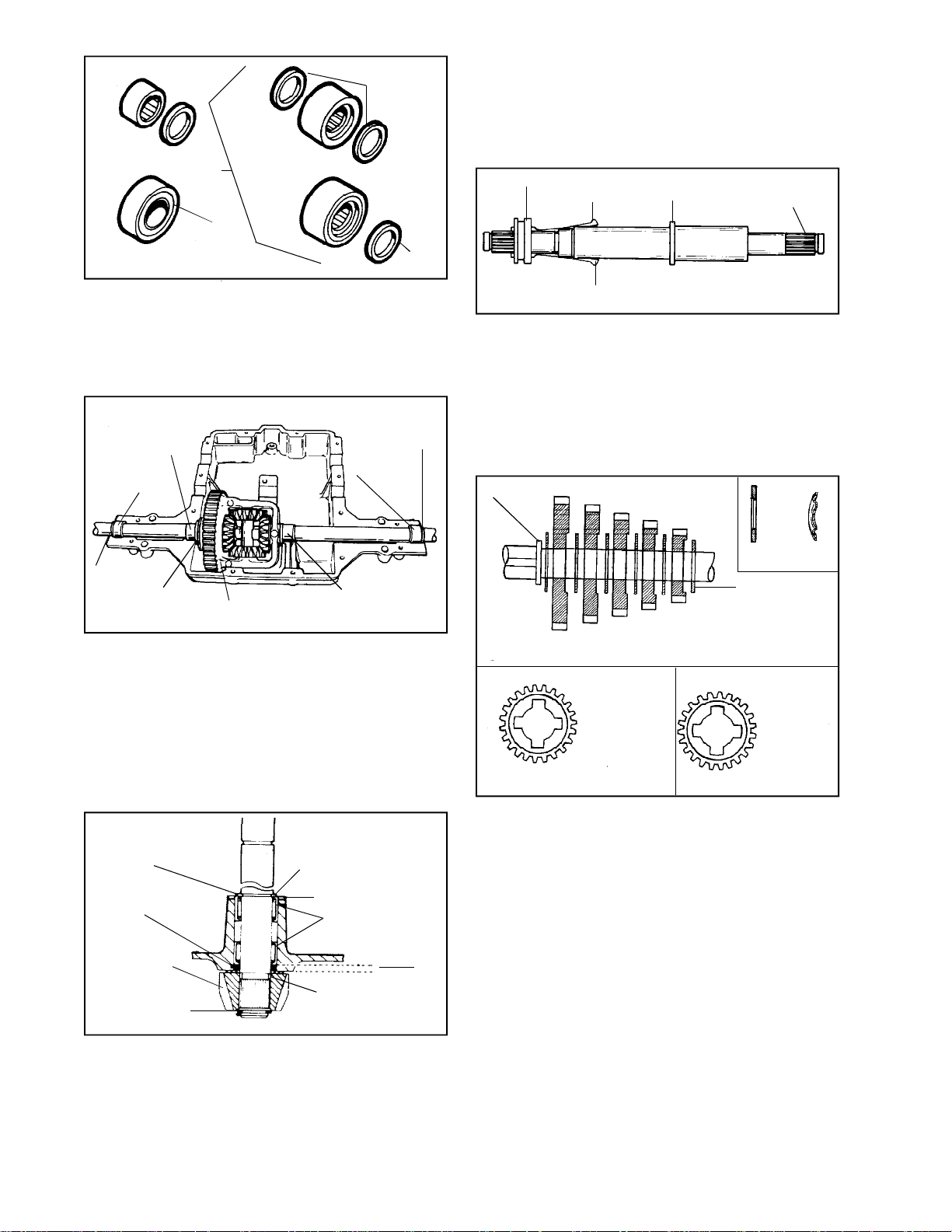
OLD STYLE
Main Menu
Main Menu
"A"
"D"
"C"
NEW STYLE
"B"
HEAVY DUTY
SEALED BALL
BEARING
SQUARE
CUT "O"
RING
SEAL
9. Remove differential from case. Remove seals
(2), needle bearings or ball bearings (2), flanged
bushings (2) and thrust washer.
Teardown and reassembly procedures for this
unit may be found in the Chapter on differentials.
E. REASSEMBLY
1. Apply E. P. grease between bearings and install
and secure the input shaft and bevel gear in
the cover. For maximum gear train life use only
Bentonite grease on all shafts and gears,
Tecumseh part number 788067B.
COLLAR
KEY
KEY
SHOULDER
DISC BRAKE
SPLINE
SHIFTER/
BRAKE SHAFT
2. Grease the keyways and slide keys and collar
on output and brakeshaft. Thick side of collar
MUST face shoulder on shaft. Service
replacement shifter/brake shafts will come with
4 keyways in the shaft instead of 2.
FLANGED
BUSHING
BEARING
SEAL
THRUST
WASHER
DIFFERENTIAL
FLANGED
BUSHING
SEAL
BEARING
The 800 Series has used 4 styles of bearings on the
axles. The earliest style “A” was a smaller loose cage
needle bearing and must have the seal to the outside
of that bearing. Style “B” must have the seal to the
outside of the bearing. When bearing style “C” is used,
a square cut “O” ring must be used on each side of
the bearing. Bearing style “D” is a sealed ball bearing
used in H.D. application. Styles “B”, “C” and “D” are
interchangeable. All needle bearings must be repacked
with grease. Do not use Bentonite grease in bearings.
NEEDLE BEARING
FLUSH WITH
HOUSING
SQUARE CUT
"O" RING
BEVEL GEAR
RETAINING RING
RETAINING RING
WASHER
NEEDLE
BEARINGS
THRUST
WASHER
INPUT
SHAFT
.135"
.150"
10. Remove retaining ring on bevel gear side from
the input shaft, remove bevel gear and pull shaft
through case. The square cut “O” ring must be
replaced, if removed. Tool Part No. 670251 is
used for removal and installation of needle
bearings for the input shaft. The needle bearing
on inboard side is installed .135/.150” below
flush.
30
NOTE: When repairing the unit used the same
number of keys removed. Do not increase or
decrease.
SHOULDER
NEW
STYLE
CUT OUT
SIDE OF
GEAR MUST
FACE
OUTBOARD
END OF
SHAFT
FLAT SIDE OF
GEAR MUST
FACE
SHOULDER
ON SHAFT
EARLY
STYLE
THRUST
WASHER
(SEPARATES
GEAR FROM
BEARING)
3. Install the thrust washers and shifting gears
onto the shifter/brake shaft. The number of gears
and/or spacer will be determined by the number
of speeds in the transmission.
WASHERS. A running change has been made
to the shifting washers. Many models have used
the thrust washer with a 45o chamfer on the
inside diameter. The latest style washer has a
curved or rounded side. The purpose of both
washers is to compress the shifting keys as
they slide into the gears. Therefore, the
chamfered or rounded side of these washers
must face the shoulder of the shaft or towards
the shifting keys. The washers are
interchangeable.
SHIFTING GEARS. The 2 sides of the shifting
gears are different. One side is flat and the
other side is cut out. The flat side of the gear
is placed onto the shaft towards the shoulder
of the shaft or towards the shifting keys.
Page 33
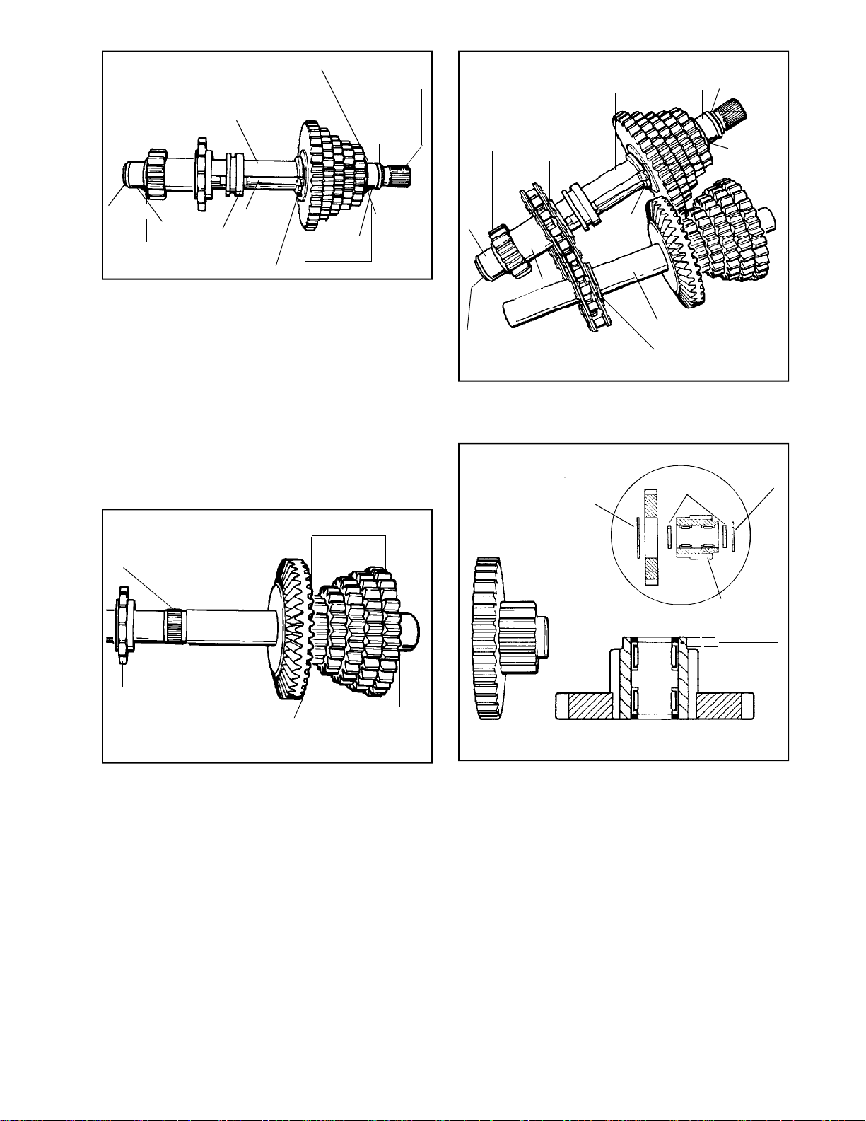
FLANGED
Main Menu
Main Menu
BUSHING
FLANGED BUSHING
SPROCKET
SHIFTER/BRAKE
SHAFT
SPLINE FOR
DISC BRAKE
SQUARE
CUT "O"
RING
FLANGED
BUSHING
SPUR
GEAR
SHIFTER/BRAKE
SHAFT
SPROCKET
COLLAR
FLANGED
BUSHING
SQUARE CUT
"O" RING
THRUST
WASHER
SQUARE
CUT "O"
RING
"V" NOTCH
THRUST
WASHER
KEY
SHIFT
COLLAR
SHIFT WASHER
"V" NOTCH
SHIFTER GEARS
THRUST
WASHER (NO
CHAMFER)
4. NOTE: The thrust washer on the shift gear end,
of the shifter and brake shaft, does not have a
chamfer on the inside diameter. Install sprocket,
spacer, spur gear, and thrust washer on output
shaft. Be sure collar on sprocket faces the shift
collar. Install bushings on both ends of shifter/
brake shaft, install square cut “O” rings on end
of flanged bushings.
NOTE: Depending on model, the bevel gear
may be installed one of two ways. For
description purposes, in this section, the model
used has the wide angle of the bevel gear facing
the left.
SPUR GEARS
SPLINE FOR CHAIN
SPROCKET GEAR
SHIFT
WASHER
SPACER
SQUARE CUT
"O" RING
COUNTERSHAFT
SPROCKET
COLLAR
6. With the shifter/brake shaft and countershaft
ends angled together, install the chain on the
sprockets.
SQUARE
CUT "O"
RING
LARGE WASHER
OUTPUT GEAR
COAT AREA
WITH GREASE
THICKER
FLAT
WASHER
OUTPUT
PINION
.135" BOTH
.150" ENDS
COUNTERSHAFT
SPROCKET
BEVEL GEAR
THRUST WASHER
FLANGED BUSHING
5. Install bevel gear and smallest to largest spur
gears, thrust washer and bushing to the counter
shaft. Install the sprocket.
7. For correct positioning of the needle bearings
use removal and installation Tool Part No.
670252. Fill the area between the needle bearings
with grease before installing on the countershaft.
31
Page 34
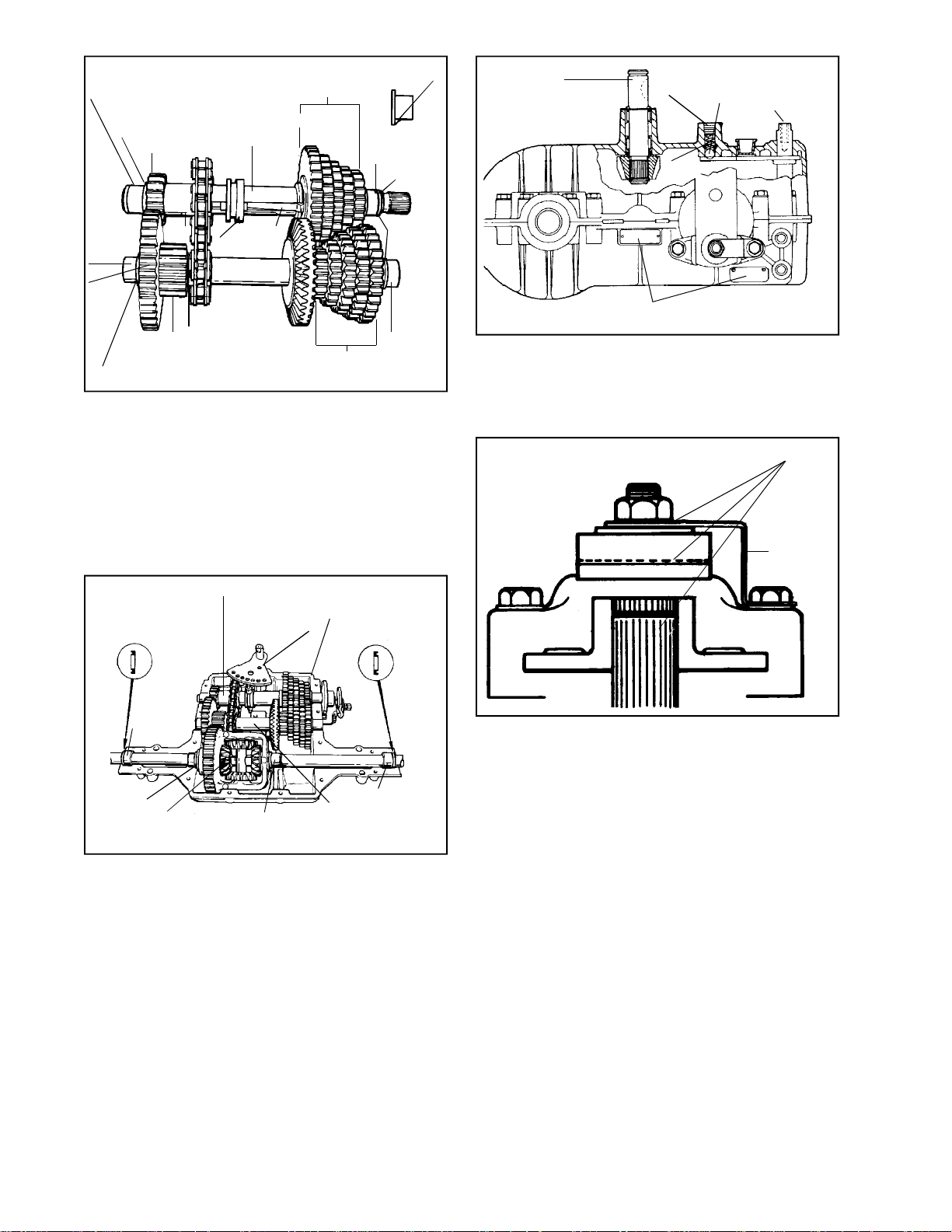
FLANGED
Main Menu
Main Menu
BUSHING
THRUST
WASHER
NEEDLE
BEARING
(CLOSED
END) OR
BALL
BEARING
OUTPUT
GEAR
OUTPUT
PINION
FLAT WASHER
SPUR GEAR
SPACER
FLAT WASHER
(SQUARE CUT SEAL
IN EACH END OF
OUTPUT PINIOIN)
SHIFTER GEARS
SHIFTER/BRAKE
SHAFT
KEY
COLLAR
SPUR
GEARS
"V" NOTCH
SQUARE CUT
FLANGED
BUSHING
"O" RING
THRUST
WASHER
FLANGED
BUSHING
8. Install the output and pinion gears, the flat
washer, square cut rings, needle bearing (closed
end), and spacer on one end and thrust washer
and flanged bushing on the other end. Note
that the “V” notch on the bushing fits into recess
“V” in case.
INPUT SHAFT
SET
SCREW
SPRING
IDENTIFICATION TAG
INDEX
BALL
FAN
SHAFT
ROD
12. Install index ball, spring and setscrew in that
order into cover, and slowly tighten the screw
1 turn below flush. If unit contained a neutral
start switch install. Check for binding by turning
input shaft.
APPLY LUBRIPLATE
A square cut seal fits in each recessed end of
output pinion. Also one square cut ring fits into
recessed end of needle bearings (closed end).
SHIFTER/BRAKE SHAFT
OIL SEAL
BEARING
FLANGED
BUSHING
DIFFERENTIAL
SHIFTER FAN
FLANGED
BUSHING
CASE
HALF
OIL SEAL
COUNTERSHAFT
9. DIFFERENTIAL ASSEMBLY
Install the flanged bushings (2), flat washer,
needle bearings or ball bearings (2), and oil
seals (2), with seal grooves facing out.
For teardown and reassembly of the differential,
see the Chapter on differentials.
Install differential in case.
BEARING
RETAINER
ASSEMBLY
BRAKE
BRACKET
13. Prior to installing the brake assembly, apply a
light film of lubriplate to the inside of lever portion
which contact pins, also to outside of lever
which contacts flat washer and between shaft
O.D. and bore of brake disc. Brake pads and
brake disc must be free of grease and oil. Install
brake assembly.
Install transaxle on equipment. Adjust brake
linkage to disengage when clutch is engaged.
Brake and linkage may vary. Consult equipment
owner’s manual.
NOTE: If adjusted incorrectly, the brake will
do one of two things:
a. It will not brake (stop) the vehicle when
the brake is applied or,
32
10. Install shifter assembly, and pack 30 oz. (36
oz. 801 Series) of Bentonite grease around
bearings and gearing, then reinstall cover on
case. Torque cap screws 90-100 inch pounds.
11. NOTE: On reassembly use either gasket
eliminator Loctite 515 (part number 510334) or
silicone RTV Loctite 598 (part number 788093).
b. If adjusted too tightly, a drag or continued
braking effect will be evident until the brake
wears out.
Page 35
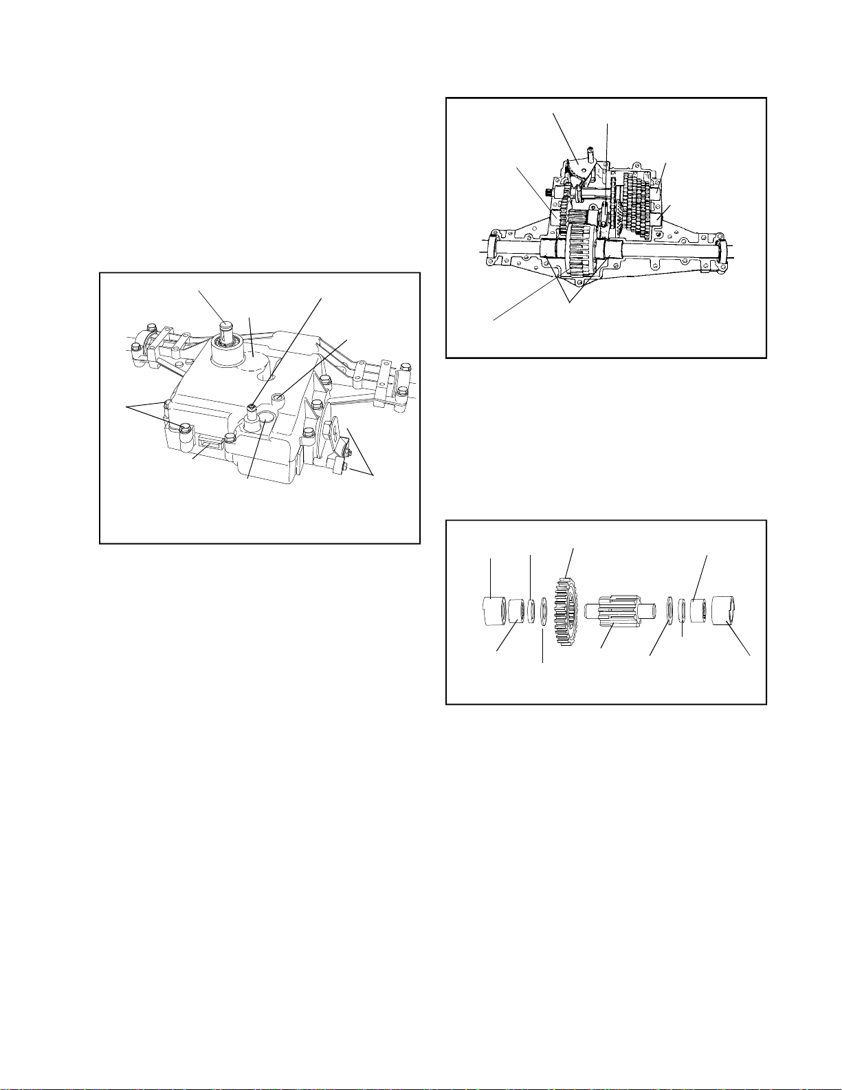
SECTION 4. 820 SERIES
Main Menu
Main Menu
CAUTION:
TO AVOID PREMATURE TRANSAXLE FAILURE,
DECLUTCHING IS REQUIRED WHEN SHIFTING
FROM NEUTRAL TO FIRST OR REVERSE; FROM
ANY FORWARD TO REVERSE GEAR OR WHEN
OPERATING EQUIPMENT ON A HILL OR UNDER
HEAVY LOAD.
NOTE: Due to the many variations of equipment braking
systems, adjustment and repair to the components
and linkages are not considered warranty.
INPUT SHAFT
COVER/CASE
HEX SCREWS
(17)
IDENTIFICATION
TAG
NEUTRAL START
SWITCH
LOCATION
(OPTIONAL)
OPTIONAL
INPUT
LOCATION
SHIFT ROD
INDEX BALL,
SPRING AND
SET SCREW
BRAKE BRACKET
SCREWS (BRAKE
CAN BE ON RIGHT
OR ON LEFT SIDE)
A. GENERAL
SHIFT FAN
OUTPUT
SHAFT
ASSEMBLY
DIFFERENTIAL
BEARING CAP
SHIFTER/BRAKE
SHAFT ASSEMBLY
COUNTERSHAFT
ASSEMBLY
SLEEVED NEEDLE BEARINGS
NOTE: Remove grease from the unit as parts
are removed. Remove the shift fan prior to
removal of the gear shaft assemblies from the
case. It will be difficult to keep parts from falling
off the assemblies, note position of parts before
removal.
4. Remove bearing cap, differential, shift fan, output
shaft assembly and then both the shifter/brake
shaft and countershaft simultaneously.
BEARING
SLEEVE
"O" RING
OUTPUT GEAR
NEEDLE
BEARING
The 820 series is similar to the 920 series transaxle
in basic operation. It has up to 6 speeds forward
and 1 reverse. The 820 series is a heavy duty unit
which is suited for ground engaging attachments.
B. IDENTIFICATION
This unit contains an aluminum tag showing the
model number.
C. PRE-DISASSEMBLY
1. Clean the outside surface of the transaxle.
2. Position the shift lever in the neutral position.
3. Remove set screw, spring and index ball.
4. If installed (O.E.M. option), remove neutral start
switch.
D. DISASSEMBLY
1. Remove hex screws that hold cover to case.
2. Push the shift lever rod in while pulling cover
off of the case. Shifting assembly may
temporarily re main in case. Remove cover.
3. Remove two brake bracket screws and remove
brake assembly.
NEEDLE
BEARING
THRUST
WASHER
OUTPUT
PINION
"O" RING
THRUST
WASHER
5. OUTPUT PINION AND SHAFT.
Remove sleeved needle bearings. Remove large
thrust washers and large output gear. The output
pinion gear is machined directly onto the output
shaft in most models. There is at least one
model in which the output shaft is splined to
accept a splined output pinion gear and a splined
output gear.
BEARING
SLEEVE
33
Page 36
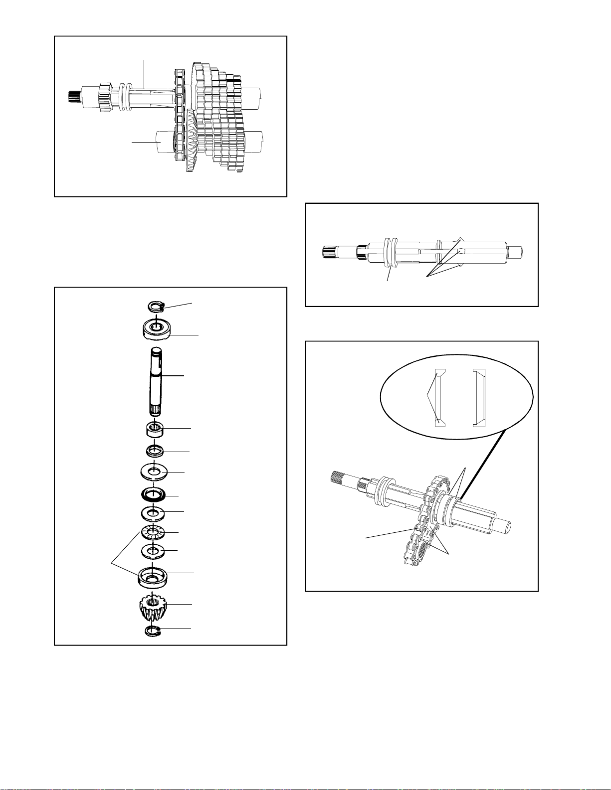
SHIFTER/BRAKE
Main Menu
Main Menu
SHAFT ASSEMBLY
COUNTERSHAFT
ASSEMBLY
6. COUNTERSHAFT AND SHIFTER/BRAKE
SHAFT
As these assemblies are taken apart, lay the
parts out in a systematic order. This will help
to make reassembly easier and inspection of
all parts possible. Clean each part of grease
as the parts are laid out.
8. DIFFERENTIAL
Refer to the Chapter on differentials for service.
Should disassembly of the differential be
necessary, 2 oz. of bentonite grease should
be placed around the gears on reassembly.
E. REASSEMBLY
NOTE: Do not apply Bentonite grease to needle
bearings. Use any type of axle grease or its
equivalent. For maximum gear train life use only
Bentonite grease on all shafts and gears, Tecumseh
part number 788067B.
1. Install the input shaft, and all the associated
parts in the order shown on the input shaft
breakdown.
SHIFTER/BRAKE SHAFT
SHIFT COLLAR
SHIFT KEYS (4)
GREASE
THESE
AREAS
7. INPUT SHAFT
The input shaft can also be removed and
inspected or serviced. Remove the snap ring
on the bevel gear and pull the shaft through
the cover. The seal must be replaced if the
shaft is removed.
34
SNAP RING
BALL
BEARING
INPUT SHAFT
NEEDLE BEARING
SEAL
THRUST WASHER (Large)
"O" RING
THRUST WASHER (Small)
THRUST BEARING
THRUST WASHER
CUPPED THRUST
WASHER
INPUT PINION
SNAP RING
2. Grease all four keyways, insert keys into collar
and keyways and slide onto the shifter/brake
shaft.
LARGE
INNER
DIAMETERS
FACE EACH
OTHER
NEUTRAL
SPACERS
SPROCKET
COLLARS
REVERSE
CHAIN
LARGER RADIUS
SPACE TOWARD
SHIFT KEYS
3. It is easier to assemble this transaxle if the
countershaft and the shifter/brake shaft are
assembled at the same time. Start by placing
the reverse chain over the reverse sprockets.
Make sure that the collars on the sprockets
are on the same side of the chain and install
the larger sprocket onto the shifter/brake shaft
with the collar away from the shifting keys.
Place the neutral spacers onto the shifter/brake
shaft with larger inner diameter sides facing
together, and the spacer with the largest inner
diameter radius toward the shift keys. Push
the shifting keys through the reverse sprocket
and the first neutral spacer, pull the neutral
spacers and the reverse sprocket up against
the shoulder of the shifter/brake shaft.
Page 37
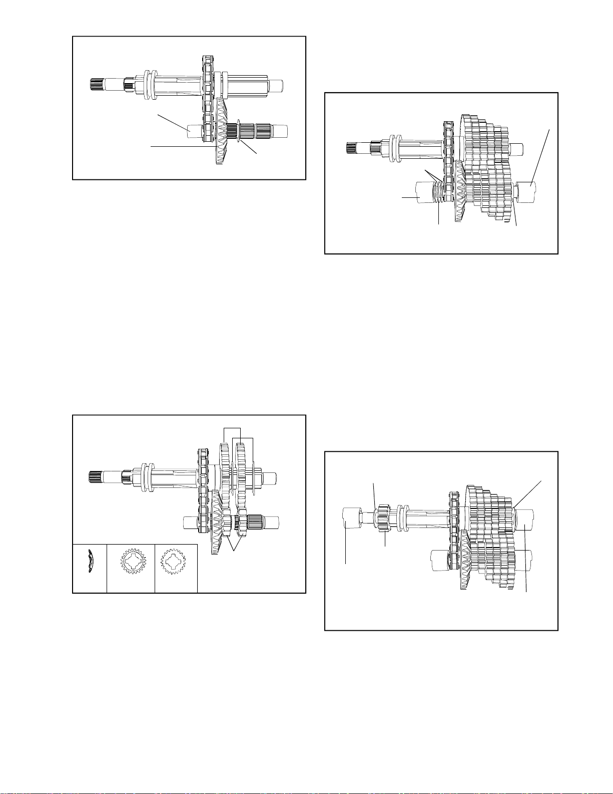
NOTE: It is not only important that gears match
Main Menu
Main Menu
up diameter-wise, but must match up according
to thickness. As all the gears are placed back
into the assembly, each should be packed with
Bentonite grease.
COUNTERSHAFT
LARGE INPUT
BEVEL GEAR
THRUST
WASHER
4. Insert the countershaft into the smaller reverse
sprocket. Then install the large bevel gear, with
the bevel facing away from the reverse sprocket.
Place thin thrust washer on the countershaft
next to the bevel gear.
NOTE: Depending on model, the bevel may
be in stalled one of two ways. For description
purposes, in this section, the model used has
the bevel side of the large bevel gear facing
away from the reverse sprocket; in other models
the bevel may face toward the reverse sprocket.
In either case there is a thrust washer placed
on the counter shaft after the large bevel gear.
Some models may also have the smallest spur
gear machined onto the countershaft in this
case the large bevel gear must be placed onto
the countershaft prior to inserting shaft into
the reverse sprocket. These models will not
have a thrust washer placed next to the large
bevel gear.
SHIFT GEARS
SHIFT
WASHERS
BEARING
ASSEMBLY
THRUST WASHERS
SLEEVE NEEDLE
BEARING "O"
RING ASSEMBLY
THRUST
BEARING
SPACER
WASHER
6. In the model pictured, a thrust washer, thrust
bearing, thrust washer and sleeved needle
bearing with “O” ring are placed on the
countershaft next to the reverse sprocket. Place
a spacer washer and sleeved needle bearing
with “O” ring next to largest spur gear. The
sleeved needle bearing installation will have
the step facing outward and the wider portion
of the bearing sleeve toward the cover. This
will be true for all future sleeve bearing
installations.
NOTE: On models with the large bevel gear
facing in the opposite direction the thrust washer,
bearing and thrust washer will be placed next
to the largest spur gear and the spacer washer
will be placed next to the reverse sprocket.
SPUR GEARS
SHIFTING
WASHER
CUT OUT SIDE
FLAT SIDE
5. Build the gears on the countershaft and shifter/
brake shaft alternately, meshing each gear with
it’s mating gear on the other shaft. The first
gear on the shifter/brake shaft would be the
largest of the shifting gears. Place this gear
next to the neutral spacer with the flat side of
the gear next to the spacer. Place a shifting
washer onto the shifter/brake shaft with the
rounded edge towards the shifting keys. Continue
this procedure until all the gears on both shafts
have been added.
THRUST
WASHER
SPUR GEAR
BEARING
ASSEMBLY
THRUST
WASHER
BEARING
ASSEMBLY
7. Place large thrust washer next to the last shifting
gear (this may be a step washer on some models)
then a sleeved needle bearing with “O” ring.
Place the spur gear, small thrust washer and
sleeved needle bearing with “O” rings on the
opposite end of the shifter/brake shaft.
NOTE: Dependent on whether the brake is on
the right or on the left, will determine which
end uses a capped sleeved needle bearing.
35
Page 38
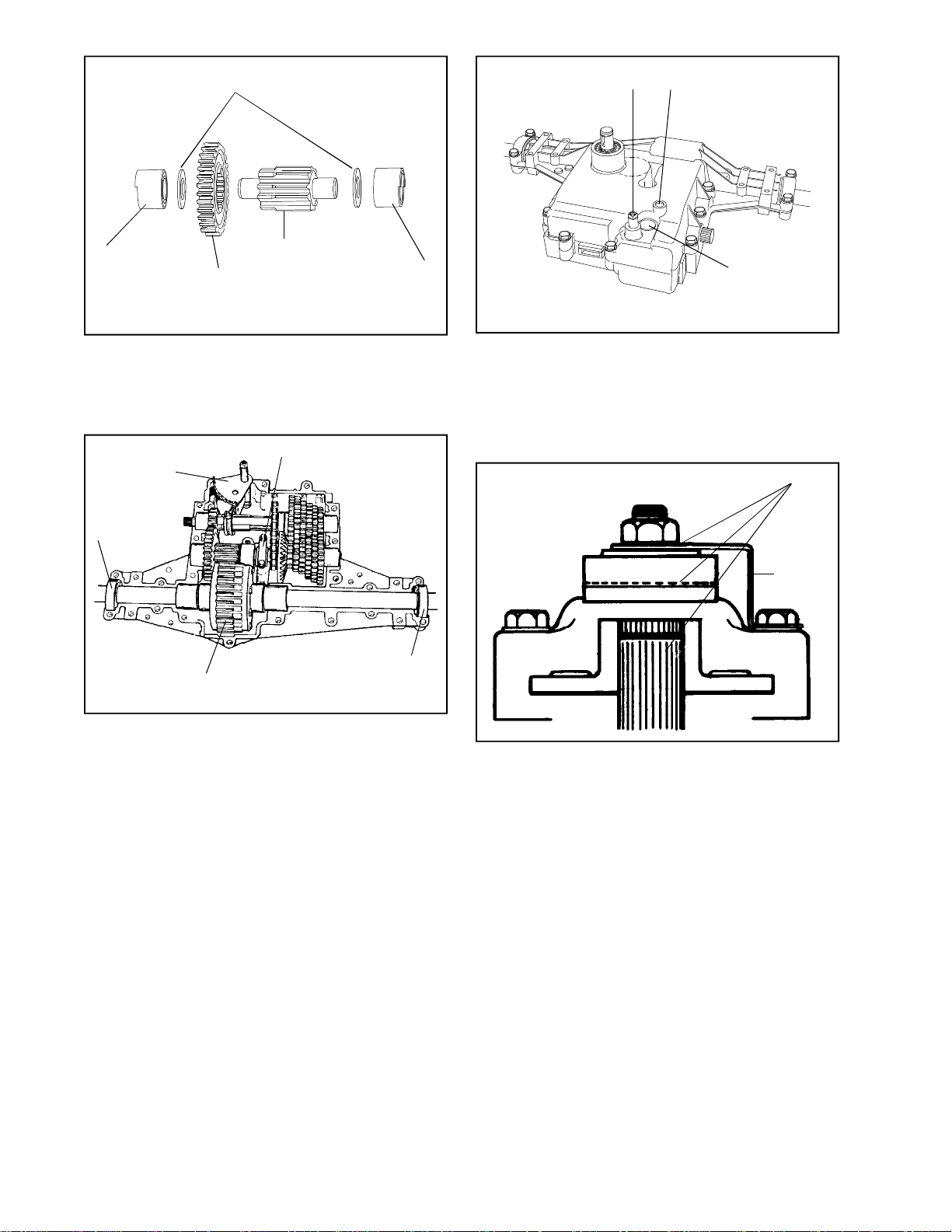
THRUST
Main Menu
Main Menu
WASHER
SHIFT ROD
INDEX SET SCREW
SLEEVED
BEARING
ASSEMBLY
OUTPUT GEAR
OUTPUT PINION
SLEEVED
BEARING
ASSEMBLY
8. Place the output gear on the stepped end of
the output pinion. Place thrust washers on each
end and then the large sleeved needle bearings.
Install the three shaft assemblies into the case.
SHIFTER
ASSEMBLY
BALL BEARING
DIFFERENTIAL
BEARING CAP
BALL BEARING
NEUTRAL START
SWITCH
11. Guide cover over shift rod and position onto
case. Torque cover screws 180-216 inch
pounds. Replace index ball, spring and set screw
and turn set screw one (1) turn below flush.
Install the neutral start sensing switch if
applicable. Check for binding by turning input
shaft.
APPLY LUBRIPLATE
BRAKE
BRACKET
9. Insert differential into case, position the caged
ball bearings on the axle ends into the recessed
areas of the case. Place the bearing cap over
the sleeved needle bearing of the countershaft
and torque bolts 90-100 inch pounds. Install
shift fan and pack transaxle with remaining
Bentonite grease. (36 oz. total)
10. Clean mating surfaces of case and cover; place
a continuous thin bead of sealant all around
the seam. Use Loctite Gasket Eliminator #515,
Tecumseh Part No. 510334 or the Loctite Silicone
RTV 598, Tecumseh Part No. 788093.
12. Prior to installing the brake assembly, apply a
light film of lubriplate to the inside of lever portion
which contact pins, also to outside of lever
which contacts flat washer and between shaft
O.D. and bore of brake disc. Brake pads and
brake disc must be free of grease and oil. Install
brake assembly.
Install transaxle on equipment. Adjust brake
linkage to disengage when clutch is engaged.
Brake and linkages may vary. Consult equipment
owner’s manual.
NOTE: If adjusted incorrectly, the brake will
do one of two things:
a. It will not brake (stop) the vehicle when
the brake is applied, or,
b. If adjusted too tightly, a drag or continued
braking effect will be evident until the brake
wears out.
36
Page 39
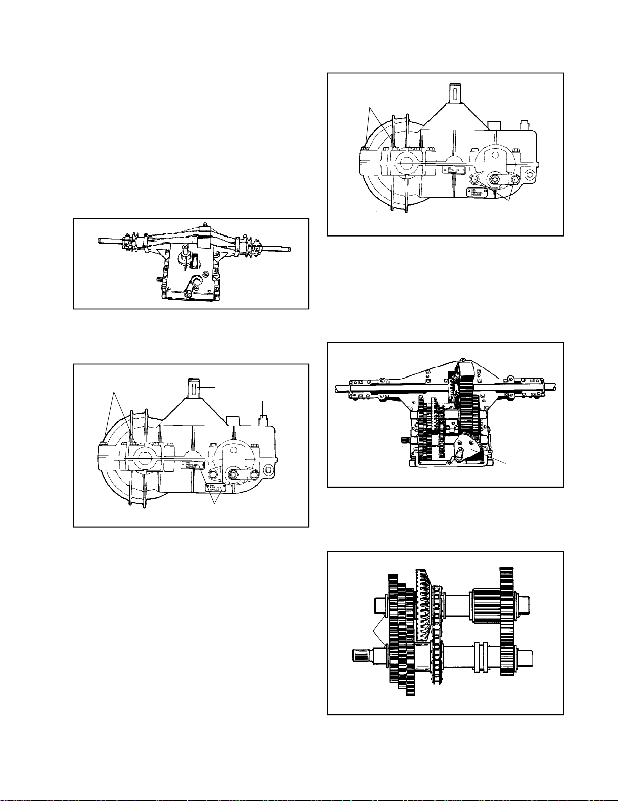
SECTION 5. 900 SERIES
Main Menu
Main Menu
CAUTION
TO AVOID PREMATURE TRANSAXLE FAILURE,
DECLUTCHING IS REQUIRED WHEN SHIFTING
FROM NEUTRAL TO FIRST OR REVERSE, FROM
ANY FORWARD TO REVERSE GEAR, FROM
REVERSE TO ANY FORWARD GEAR OR WHEN
OPERATING EQUIPMENT ON A HILL OR UNDER
HEAVY LOAD.
NOTE: Due to the many variations of equipment braking
systems, adjustments and repair to these components
and linkages are not considered warranty.
A. GENERAL
The 900 series is like the 800 series transaxle. It
has 1, 2, 3 or 4 speeds forward and 1 reverse.
COVER CASE
HEX
SCREWS
BRAKE
BRACKET
SCREWS
D. DISASSEMBLY
1. Remove hex screws that hold cover to case.
2. Push shift lever rod in while pulling cover off
of case. Shifting assembly may temporarily
remain in case. Remove cover.
3. Remove two brake bracket screws and remove
brake assembly.
COVER CASE HEX
SCREWS
A
INPUT
SHAFT
SHIFT ROD
B
ID TAG
B. IDENTIFICATION
This unit contains an aluminum tag at location A
or B, showing the model number.
C. PRE-DISASSEMBLY
1. Clean outside surface of transaxle.
2. Position shift lever in neutral position.
3. Remove set screw, spring and index ball.
4. If installed (O.E.M. option), remove neutral start
switch.
SHIFT FORK
FAN ASSY.
NOTE: Remove grease from the unit as parts are
removed. Prior to removal of gear shaft assemblies
from the case, the shifter fan may be removed. It
will be difficult to keep parts from falling off the
assemblies. Note position of parts before removal.
"V"
NOTCHES
4. Remove gear and shaft assemblies from case
half. NOTE: Before disassembly, observe how
“V” notches on the flange bushings fit into recess
“V” of case.
37
Page 40
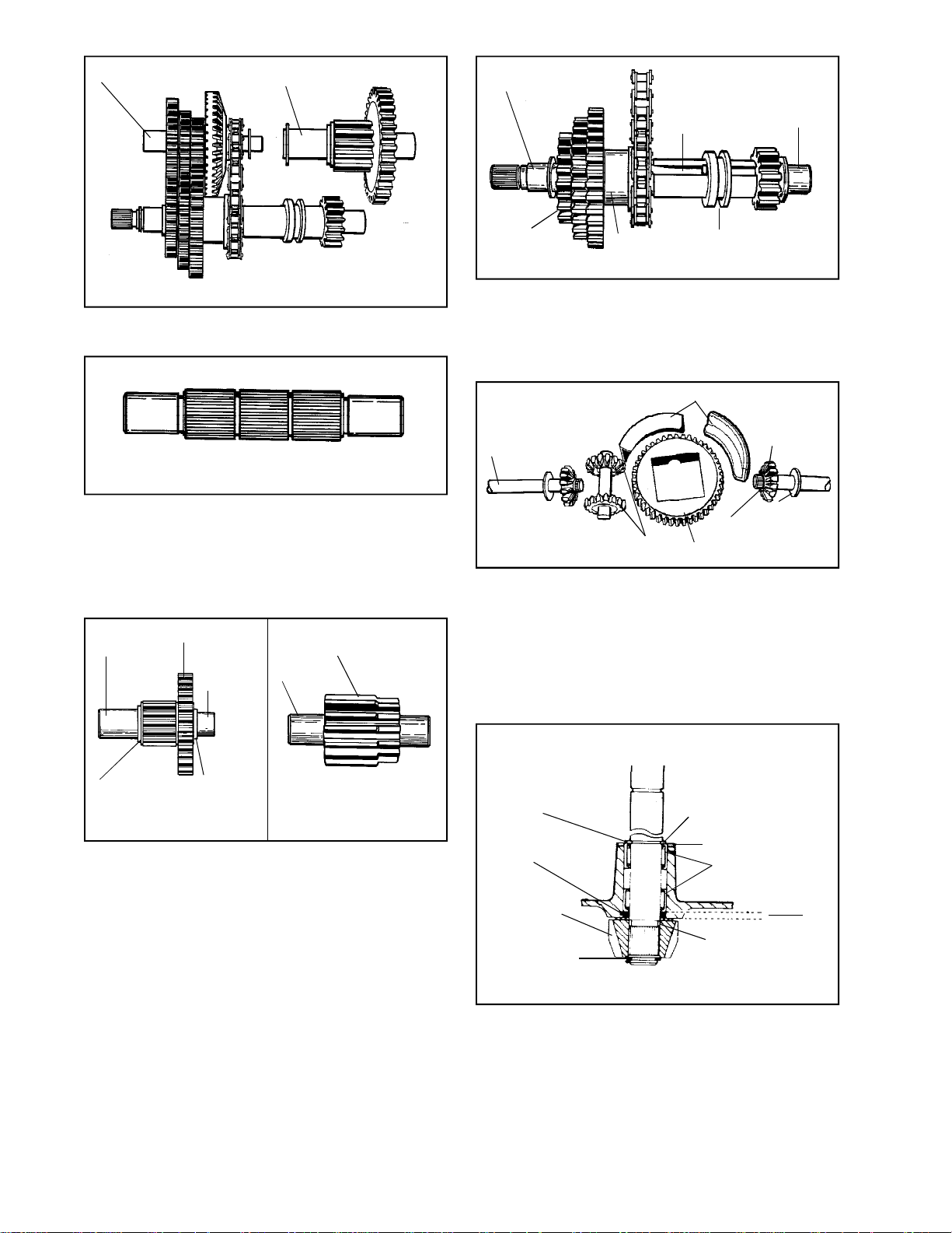
COUNTERSHAFT
Main Menu
Main Menu
BUSHING
BUSHING
5. To disassemble countershaft, output pinion and
shaft assembly, simply pull apart.
COUNTERSHAFT
6. COUNTERSHAFT
Remove the two (2) thrust washers, sprocket,
bevel gear, spur gears and flanged bushing.
The sprocket, bevel gear and spur gears are
splined to the countershaft.
BUSHING
OUTPUT GEAR
BUSHING
SHAFT
PINION GEAR
KEY
SHIFTER
GEAR
NEUTRAL
SPACER
SHIFTER
COLLAR
8. SHIFTER SHAFT
Remove the square cut “O” ring (1) and flanged
bushings (2), thrust washers (2) on shaft ends,
shift collar with keys, sprocket, spacer, shifter
gears and thrust washers.
BEARING BLOCKS
AXLE
2 SNAP RINGS
BEVEL PINIONS
RING GEAR
9. DIFFERENTIAL
Remove the top bearing block on the bull gear
of the differential. Remove the bull gear, bevel
pinion gears with center shaft and the axles.
Grasp the axle bevel gears between your thumb
and fingers, hold together while lifting differential
from case. Remove bottom bearing block from
case.
BUSHING
BEVEL
GEAR
WASHER
38
WASHER
WASHER
7. OUTPUT PINION AND SHAFT
Remove the large brass bushing, large washer,
large output gear, washer and bushing. The shaft
and output pinion gear come as an assembly.
NEEDLE BEARING
FLUSH WITH
HOUSING
SQUARE CUT
"O" RING
BEVEL GEAR
RETAINING RING
RETAINING RING
WASHER
NEEDLE
BEARINGS
THRUST
WASHER
10. INPUT SHAFT
Remove retaining ring on bevel gear end from
the input shaft, remove bevel gear and pull shaft
through case. The square cut “O” ring must be
replaced, if removed.
Tool part no. 670251 is used for removal and
installation of needle bearings for the input shaft.
The needle bearing on inboard side is installed
.135/.150” below flush.
INPUT
SHAFT
.135"
.150"
Page 41
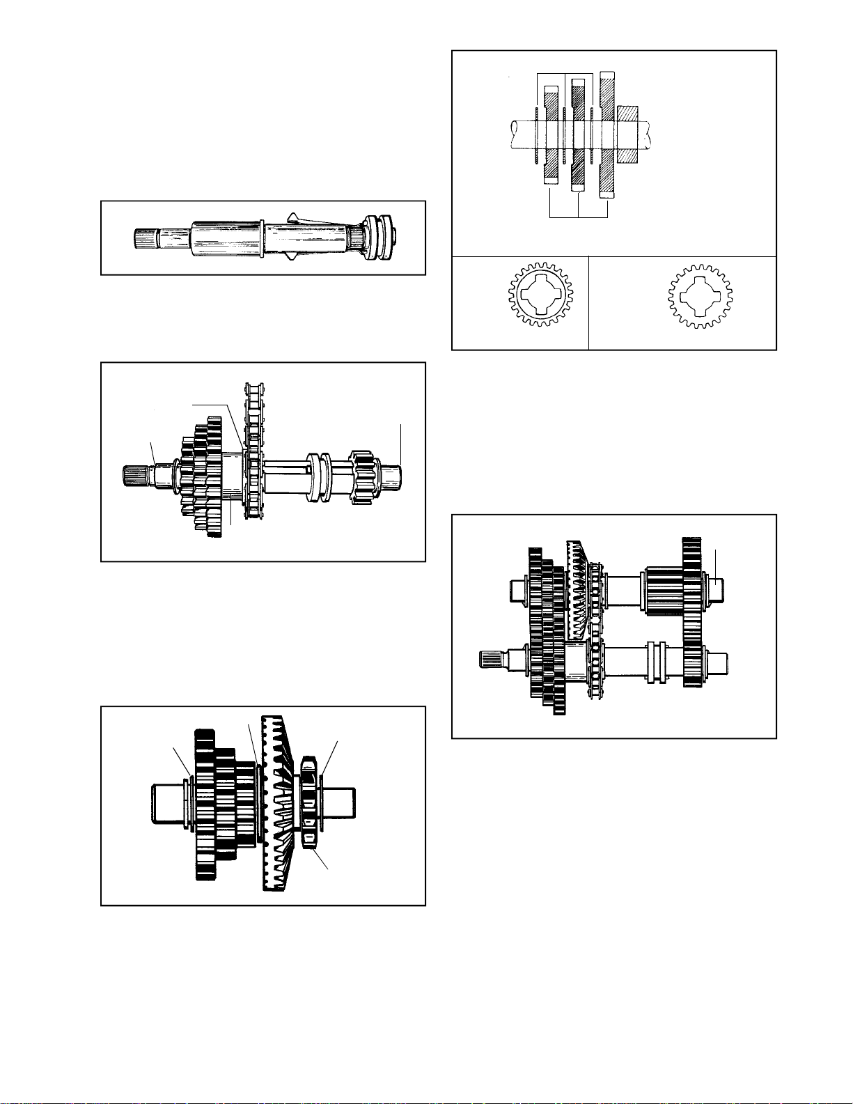
E. REASSEMBLY
Main Menu
Main Menu
1. Apply E.P. grease between bearings in the cover
and install the input shaft, square cut seal,
thrust washers, bevel gear and snap ring.
NOTE: Needle bearings are lubricated with E.P.
Grease. Do not use Bentonite on any needle
bearing. For maximum gear train life use only
Bentonite grease on all shafts and gears,
Tecumseh part number 788067B.
SHIFT WASHERS
SHIFTING GEARS
2. Grease both keyways and slide keys and collar
on shifter/brake shaft.
When reassembling the 900 series it is easier
to assemble the shifter/brake shaft and the
countershaft at the same time.
REVERSE
SPROCKE
COLLAR
"O" RING
NEUTRAL
SPACER
"O" RING
3. Place the reverse chain on the reverse
sprockets. The collars of the reverse sprockets
should be on the same side of the chain. Slide
the larger sprocket onto the shifter/brake shaft
with the collar away from the shifting keys and
shoulder on the shifter/brake shaft. Slide the
keys through the sprocket and install the neutral
spacer over the ends of the shifting keys and
pull them back until the sprocket touches the
shoulder of the shaft.
THRUST
WASHER
WASHER
THRUST
WASHER
CUT OUT SIDE
OF GEAR
MUST FACE
OUTBOARD
END OF SHAFT
FLAT SIDE OF
GEAR MUST
FACE SHOULDER
ON SHAFT
5. Place the largest of the shifting gears with the
flat side of the gear next to the neutral spacer.
Then place a shifting washer with the chamfer
on the inside diameter of the washer next to
the gear. The chamfer or rounded side must
face towards the shifting keys.
NOTE: As all the gears are placed back into
the assembly, each should be packed with
Bentonite grease.
LARGE
BUSHING
6. Then place a thrust washer on each end of the
countershaft and a bushing on the end with
the largest gear.
SPROCKET
4. Insert the splined countershaft into the smaller
reverse sprocket. Then place the large beveled
gear on the countershaft with the beveled side
of the gear towards the reverse sprocket. If
the 900 series is a 1, 2, or 3 speed forward
unit, place a washer over the shaft and next to
the backside of the large bevel gear. If the unit
is a 4 speed for ward there will not be a washer
in this location. Then begin to place the spur
gears onto the countershaft, alternating with
it’s mating gear on the shifter/brake shaft.
7. Place a larger thrust washer next to the smallest
shifting gear, then the bronze bushing and then
an “O” ring.
NOTE: Some units will use a stepped thrust
washer; place the washer onto the shaft so
that the step in the washer is out and away
from the shifting gears.
8. The end of the shifter/brake shaft (end opposite
the shifting gears) has a spline. Install the spur
gear that drives the output gear onto this spline.
Then the thrust washer, bushing and “O” ring.
39
Page 42
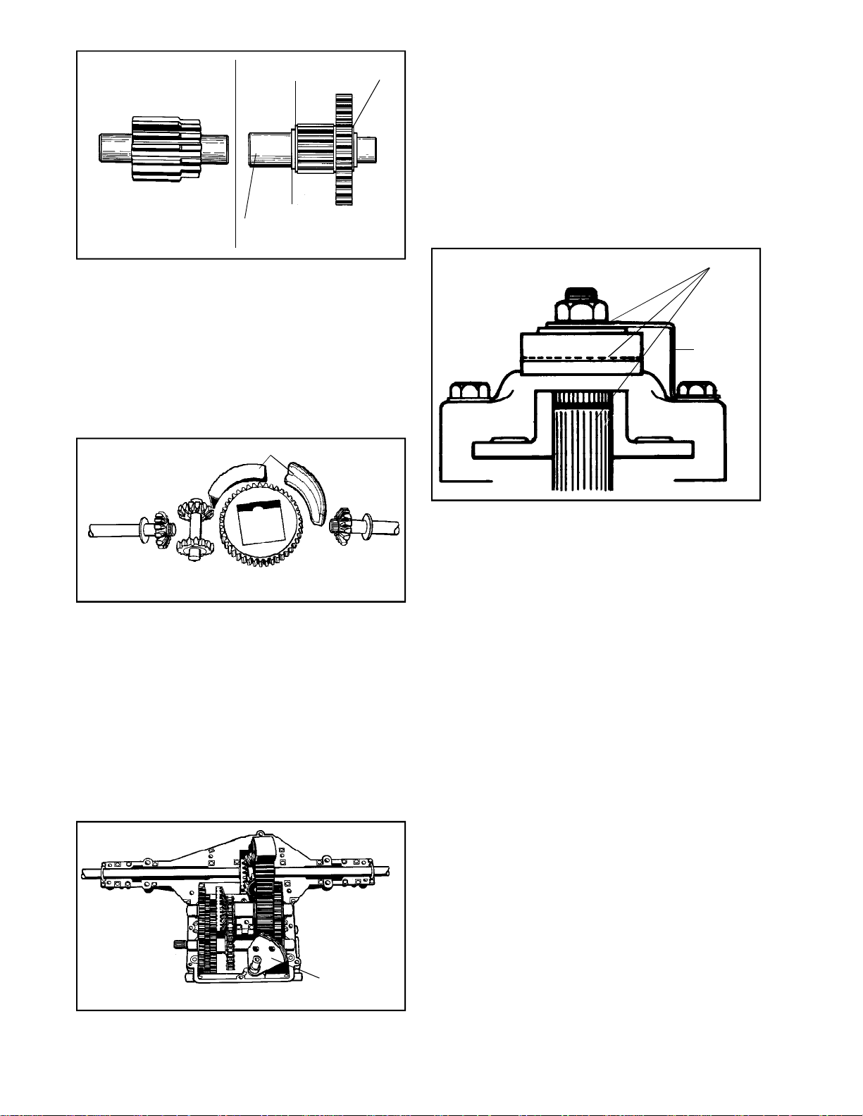
WASHER
Main Menu
Main Menu
FLAT
BRONZE
BUSHING
WASHER
9. To assemble the output shaft assembly, place
a washer and then the bronze bushing with
collar, (flat down), next to the pinion. Place
output gear over pinion as in picture. There is
a washer on outside of gear.
10. After both shafts are completed, place the
flanged bushings on each end. Notice one is
larger than the other.
NOTE: That the “V” notch on the bushing fits
into recess “V” in case.
BEARING BLOCK
14. Clean the mating surfaces of case and cover;
place a continuous thin bead of sealant all
around the seam. Use Loctite Gasket Eliminator
#515, Tecumseh part number 510334 or the
Loctite Silicone RTV 598, Tecumseh Part number
788093.
15. Install index ball, spring, and set screw in that
order into cover, and slowly tighten the screw
one (1) turn below flush. If unit contains a neutral
start switch install.
Check for binding by turning input shaft.
APPLY LUBRIPLATE
BRAKE
BRACKET
11. DIFFERENTIAL ASSEMBLY
When assembling this unit, make sure all parts
are there first, because the unit is put together
in your hands and placed in the case at the
same time. Axles and gears must be on center
line of ring gear.
Bearing block in case must have flange to the
left hand side. Block in cover must have flange
to the right hand side.
12. Before installing the differential into the case,
apply Bentonite grease to the axle bearing areas.
16. Prior to installing the brake assembly, apply a
light film of lubriplate to the inside of lever portion
which contact pins, also to outside of lever
which contacts flat washer and between shaft
O.D. and bore of brake disc. Brake pads and
brake disc must be free of grease and oil. Install
brake assembly.
Install transaxle on equipment. Adjust brake
linkage to disengage when clutch is engaged.
Brake and linkage may vary. Consult equipment
owner’s manual.
NOTE: If adjusted incorrectly, the brake will
do one of two things:
a. It will not brake (stop) the vehicle when
the brake is applied, or,
b. If adjusted too tightly, a drag or continued
braking effect will be evident until the brake
wears out.
40
SHIFT FORK
FAN ASSY.
13. Install shifter assembly and pack 26 oz.
Bentonite grease around bearings, gearing, and
top of shift fan then reinstall cover on case.
Torque cap screws 90-100 inch pounds.
Page 43
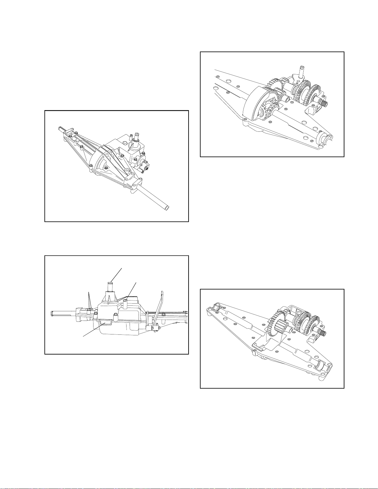
SECTION 6. 910 SERIES
Main Menu
Main Menu
CAUTION
TO AVOID PREMATURE TRANSAXLE FAILURE,
DECLUTCHING IS REQUIRED WHEN SHIFTING
FROM NEUTRAL TO FORWARD OR REVERSE;
FROM FORWARD TO REVERSE GEAR.
NOTE: Due to the many variations of equipment braking
systems, adjustment and repair to the components
and linkages are not considered warranty.
A. GENERAL
The 910 series is available in 1 speed forward and
1 reverse.
D. DISASSEMBLY
1. Remove the hex head screws that hold the
cover to the case.
2. Push the shift lever rod while pulling cover off
the case. The shifting lever may temporarily
remain in the case. Lift off cover.
3. Remove the two brake bracket screws and
remove brake assembly.
4. Remove the grease from the unit as the parts
are removed. Prior to removal of gear shaft
assemblies from the case, the shifter fan may
be removed. Note the position of the parts before
removal. Some parts may come off the shafts
upon removal.
INPUT SHAFT
COVER CASE
HEX SCREWS
I.D. TAG
B. IDENTIFICATION
This unit contains an aluminum tag showing the
model number.
C. STEPS TO TAKE BEFORE DISASSEMBLY.
1. Clean the outside surface of the transaxle.
2. Position the shift lever in the neutral position.
3. If installed (O.E.M. option), remove the neutral
start switch.
4. Some 910 models will have a detent ball and
spring. Remove the set screw, spring and ball.
SHIFT ROD
NOTE: BENTONITE GREASE MAY STAIN
CLOTHES. CARE SHOULD BE USED WHEN
HANDLING.
5. Remove the top bearing block on the bull gear
of the differential. Remove the bull gear, bevel
pinion gears with center shaft and the axles.
41
Page 44
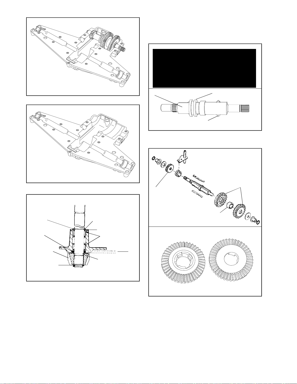
E. REASSEMBLY
Main Menu
Main Menu
1. Apply grease between the bearings in the cover
and install the input shaft, bevel gear and snap
ring.
6. Remove the output shaft assembly.
7. Remove the shifter/brake shaft assembly.
NEEDLE BEARING
FLUSH WITH
HOUSING
SQUARE CUT
"O" RING
BEVEL GEAR
RETAINING RING
RETAINING RING
WASHER
NEEDLE
BEARINGS
THRUST
WASHER
INPUT
SHAFT
.135"
.150"
SHIFTER/BRAKE SHAFT
KEYS
COLLAR
2. Grease both keyways and slide keys and collar
on shifter/brake shaft.
SPUR GEAR
SPACER
BEVEL GEARS
42
8. The input shaft can also be removed and
inspected or serviced. Remove the snap ring
on the bevel gear and pull the shaft through
the case. The square cut “O” ring must be
replaced if the shaft is removed.
Tool part No. 670251, is used for removal and
installation of needle bearings for the input shaft.
The needle bearing on the inboard side is
installed .135 .150” below flush.
NOTE: Needle bearings are lubricated with E.P.
grease. DO NOT USE BENTONITE ON
NEEDLE BEARINGS. For maximum gear train
life use only Bentonite grease on all shafts
and gears, Tecumseh part number 788067B.
BEVELED SIDE
FLAT SIDE
3. The large beveled shifting gears can be placed
onto the shifter/brake shaft. The bevels on the
gears face each other and are separated with
a neutral spacer. Push shifting keys into the
neutral spacer.
A thrust washer, a bronze bushing, and an “O”
ring are then placed on the shaft.
The spur gear, washer, bushing and “O” ring
are assembled to the other end of the shaft.
Page 45
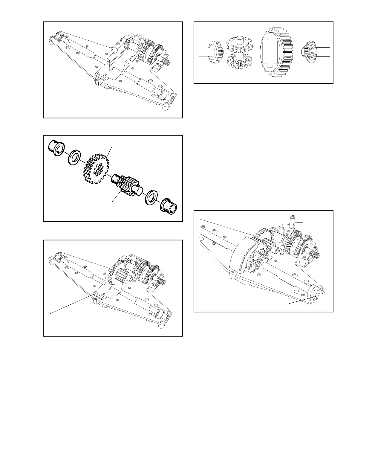
4. Place the shifter/brake shaft assembly in the
Main Menu
Main Menu
case.
OUTPUT GEAR
OUTPUT PINION
5. Place the output gear onto the output pinion.
Install the thrust washers and bushings.
NOTE: The differential must be assembled out
of the case and then placed in the case.
8. Insert the lower bearing block into the case
with the flange to the left. Place the center
shaft with the bevel pinion gears into the bull
gear of the differential. Center the bevel gear
on the longest axle with the pinion gears of the
differential. This axle goes up to the side of
the bull gear where the center shaft slipped in.
Center the bevel gear on the other axle to the
other side. Pick up the entire unit and place it
in the case as an assembly. Reposition the
rubber seals on the ends of the axles. (If
damaged, or old replace them).
NOTE: Some models will have an offset input
in those units the differential assembly begins
with the shortest axle.
SHIFTING
FAN
LOWER BEARING BLOCK
6. Insert the output shaft assembly into the case.
7. Prior to installing differential into case, apply
Bentonite grease to axle bearing surfaces.
RUBBER SEAL
9. Install the shifting fan with the pin in the groove
of the shifting collar. Grease top of shift fan.
Fill the unit with 18 oz. of Bentonite grease.
Install top bearing block with flange to the right.
10. Clean the mating surfaces of case and cover;
place a continuous thin bead of sealant all
around the seam. Use Loctite Gasket Eliminator
#515, Tecumseh part number 510334 or the
Loctite Silicone RTV 598, Tecumseh part number
788093.
11. Make sure that the tabs of all the bushings are
in their “V” notches, install the cover and torque
the cap screws to 90-100 inch pounds.
12. Reinstall the ball, spring and set screw on the
models that have them. The setting for the screw
is flush to the cover.
Check for binding by turning input shaft.
43
Page 46
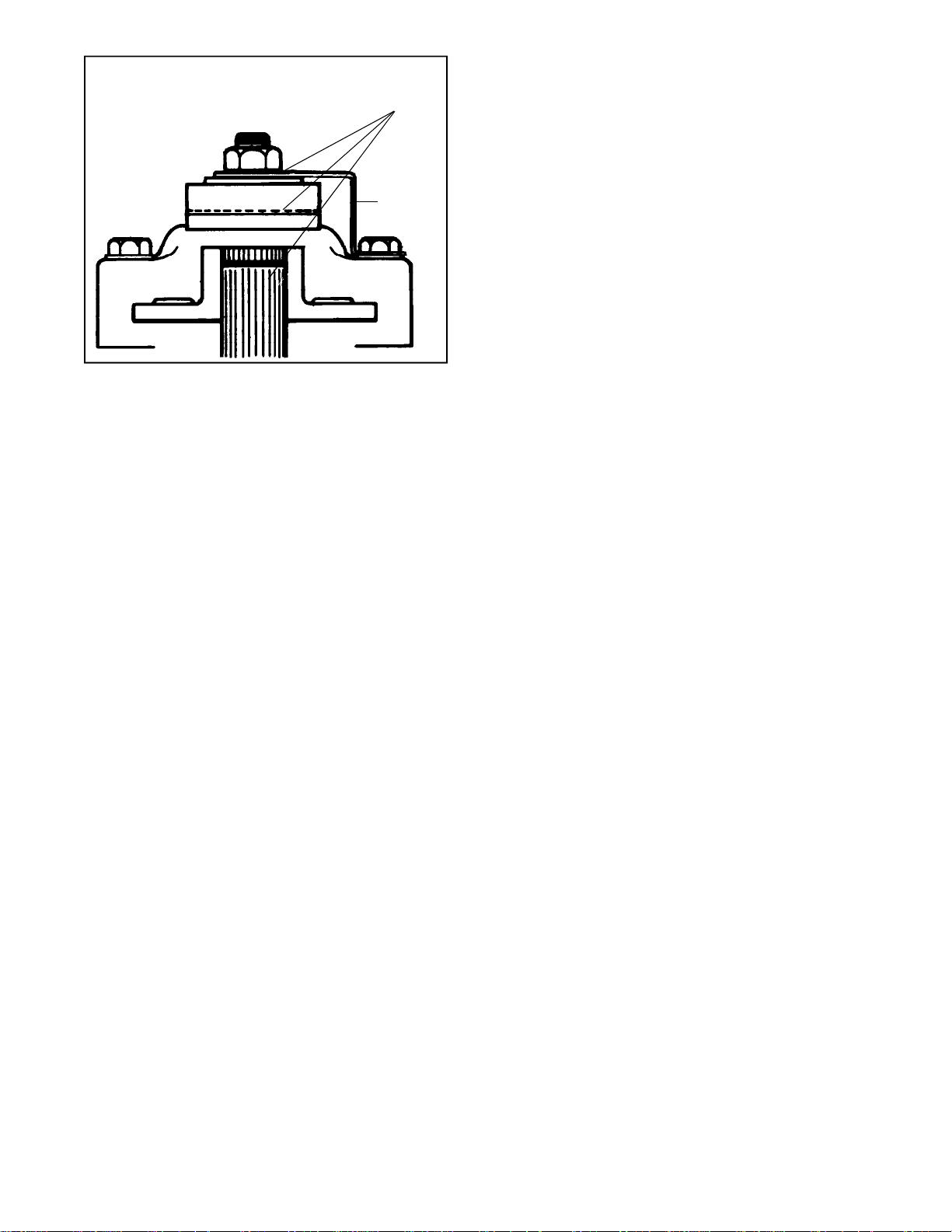
APPLY LUBRIPLATE
Main Menu
Main Menu
BRAKE
BRACKET
13. Prior to installing the brake assembly, apply a
light film of lubriplate to the inside of lever portion
which contact pins, also to outside of lever
which contacts flat washer and between shaft
O.D. and bore of brake disc. Brake pads and
brake disc must be free of grease and oil. Install
brake assembly.
Install transaxle on equipment. Adjust brake
linkage to disengage when clutch is engaged.
Brake and linkages may vary. Consult equipment
owner’s manual.
NOTE: If adjusted incorrectly, the brake will
do one of two things:
A. It will not brake (Stop) the vehicle when
the brake is applied, or,
B. If adjusted too tightly, a drag or continued
braking effect will be evident until the brake
wears out.
44
Page 47
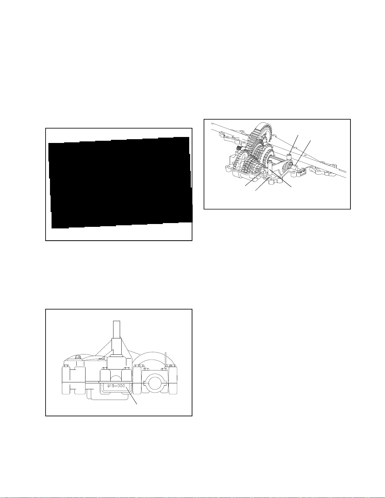
SECTION 7. 915 SERIES / 940 SERIES
Main Menu
Main Menu
CAUTION:
TO AVOID PREMATURE TRANSAXLE FAILURE,
DECLUTCHING IS REQUIRED WHEN SHIFTING
FROM NEUTRAL TO FIRST OR REVERSE; FROM
ANY FORWARD TO REVERSE GEAR OR WHEN
OPERATING EQUIPMENT ON A HILL OR UNDER
HEAVY LOAD.
NOTE: Due to the many variations of equipment braking
systems, adjustment and repair to the components
and linkages are not considered warranty.
COVER/CASE HEX
SCREWS (17)
SCREWS
OPTIONAL INPUT
LOCATION
INPUT SHAFT
NEUTRAL START
SWITCH LOCATION
(OPTIONAL)
SHIFT
RODBRAKE BRACKET
A. GENERAL
The 915 series transaxle has a sculptured case,
gear driven reverse and a unique power flow. The
915 series has 3, 4, 5 or 6 speeds forward and 1
speed reverse. The model pictured throughout this
section utilizes an A input, assembly variations
for models with a B input or reverse input will be
explained in the appropriate segment.
C. STEPS TO TAKE BEFORE DISASSEMBLY.
1. Clean the outside surface of the transaxle.
2. Position the shift lever in the neutral position.
3. If installed (O.E.M. option), remove the neutral
start switch.
4. Remove the “O” ring from the shift rod.
D. DISASSEMBLY
INDEX BALL AND
SPRING LOCATION
SHIFTER/BRAKE/
OUTPUT SHAFT
ASSEMBLY
COUNTERSHAFT
ASSEMBLY
OPTIONAL SHIFT
ROD LOCATION
SHIFT ROD
ASSEMBLY
1. Remove the hex head screws that hold the
cover to the case.
2. Push down on the shift lever rod while pulling
cover off of the case.
3. Remove the index ball and spring from the shift
rod assembly. Rotate shift rod assembly upward
to remove from shift collar.
NOTE: Some models will have the index ball
and spring on the case end of the shift rod, be
careful not to lose parts when removing shift
rod assembly.
IDENTIFICATION TAG
B. IDENTIFICATION
This unit has an aluminum tag showing the model
number, make sure tag is not misplaced during
disassembly.
4. Remove the two brake bracket screws and
remove brake assembly.
5. Remove the grease from the unit as the parts
are removed.
NOTE: BENTONITE GREASE MAY STAIN
CLOTHES. CARE SHOULD BE USED WHEN
HANDLING.
940 SERIES
The 940 Series is identical to the 915 Series with the
exception of 3 added bronze bushings. These bushings
are located on the shifter brake shaft (1) opposite the
brake rotor end. The other (2) are located on the spur
gear shaft, one on each end.
45
Page 48
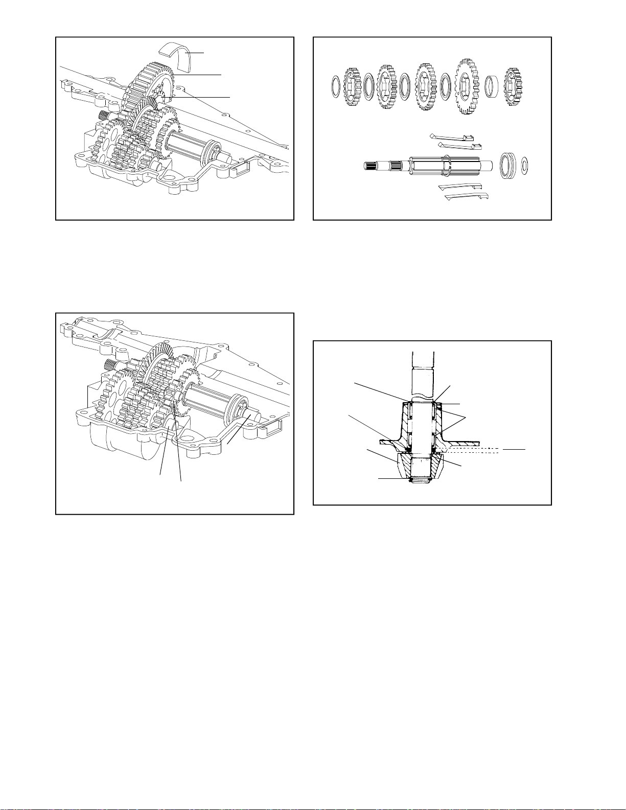
BEARING STRAP
Main Menu
Main Menu
DIFFERENTIAL
BULL GEAR
AXLE BEVEL
GEAR
6. Remove the bearing strap on the bull gear of
the differential. Remove the bull gear, bevel
pinion gears with center shaft and the axles.
Grasp the axle bevel gears between your thumb
and fingers, hold together while lifting differential
from case.
SHIFTER/BRAKE/
OUTPUT SHAFT
COUNTERSHAFT
ASSEMBLY
REVERSE IDLER
ASSEMBLY
ASSEMBLY
7. There are 2 shaft assemblies in this transaxle;
the countershaft and the shifter/brake/output
shaft assembly. Remove these assemblies as
complete as possible from the case.
8. As these assemblies are taken apart, lay the
parts out in a systematic order. This will help
to make reassembly easier and inspection of
all parts possible. Clean grease from each part
as the parts are laid out. To remove keys from
the shifter/brake/output shaft you must remove
the large snap ring from its groove. Be careful
not to stretch or twist snap ring, it is not
necessary to remove snap ring from shaft.
NEEDLE BEARING
FLUSH WITH
HOUSING
SQUARE CUT
"O" RING
BEVEL GEAR
RETAINING RING
RETAINING RING
WASHER
NEEDLE
BEARINGS
THRUST
WASHER
INPUT
SHAFT
.135"
.150"
9. The input shaft can also be removed and
inspected or serviced. Remove the snap ring
on the bevel gear and pull the shaft through
the case. The square cut “O” ring must be
replaced if the shaft is removed.
46
NOTE: Dependent on the rotation of the
countershaft gears the reverse idler assembly
will be located either above the reverse gears
and held in place by bosses in the cover or
below the reverse gears and held in place by
bosses in the case. The reverse idler assembly
will always be located against the thrust of the
countershaft reverse gear.
Tool part No. 670251, is used for removal and
installation of needle bearings for the input shaft.
The needle bearing on the inboard side is
installed .135 .150” below flush.
NOTE: Needle bearings are lubricated with EP
grease. DO NOT USE BENTONITE GREASE.
For maximum gear train life use only Bentonite
grease on all shafts and gears, Tecumseh part
number 788067B.
Page 49

E. REASSEMBLY
Main Menu
Main Menu
1. Apply grease between the bearings in the cover
and install the input shaft, square cut seal,
thrust washers, bevel gear and snap ring.
Then place a shifting washer onto the shaft
with the rounded edge towards the shifting keys.
Continue this procedure until all the gears and
washers have been added in their proper
sequence.
SNAP RING GROOVE
SNAP RING
2. Grease all keyways and slide keys and collar
onto the shifter/brake/output shaft. On models
which have a inner diameter recess cut into
one side of the shift collar, the recess side
must face towards the gears and snap ring for
proper gear selection. Place large snap ring
back into the snap ring groove. On five speed
models that do not use the large bevel gear for
the highest speed an additional neutral spacer
will be placed between the snap ring and the
shift collar.
SHIFT GEARS
SHIFT WASHERS
REVERSE SHIFT GEAR
OUTPUT GEAR
LARGE BEVEL GEAR
THIN SHIFTING
WASHER
4. The last shifting washer will be a thin flat washer
installed prior to the large bevel gear. The style
of input will determine how the large bevel gear
will be installed. In the model pictured input
“A” is used and the bevel is inward towards
the keys. On models with a “B” input the bevel
will be outward or away from the keys.
In both instances the gear cut directly onto
the large bevel gear will be toward the outside
of the case. Install a washer and then the output
gear. The output gear has an inner diameter
recess on one end, this recess must face toward
the large bevel gear. Two washers are installed
next to the out put gear followed by a bronze
bushing and rubber “O” ring. Then place a washer
on the opposite end of shaft to complete the
assembly of the shifter/brake/output shaft.
NEUTRAL SPACER
SHIFTING
WASHER
CUT OUT SIDE
FLAT SIDE
NOTE: As all the gears are placed back into
the assembly, each should be packed with
Bentonite grease.
3. The shafts in this transaxle can be assembled
separately. After replacing the snap ring into
its’ groove, place the reverse shifter gear onto
the shaft with the flat side next to the snap
ring. Push the shifting keys through the reverse
gear and push the neutral spacer over the end
of the keys and pull the neutral spacer and
reverse gear up against the snap ring. Next
place the shifting gear onto the shaft with the
flat side next to the neutral collar.
REVERSE GEAR COLLAR
LOCATION FOR SPACER
(SOME MODELS)
5. The countershaft must have the longer unsplined
end toward the outside or brake side of the
case and the shorter unsplined end toward the
shifter assembly. The wide washer or spacer
is placed on the longer unsplined end followed
by the largest spur gear.
If assembling a six speed or some five speeds
a spacer will be placed next to the largest spur
gear, on all other models leave a space the
width of the large bevel gear and then assemble
the remainder of the spur gears with the reverse
spur gear assembled with the collar side inward.
The small washer is placed next to the reverse
spur gear to complete the counter shaft
assembly.
47
Page 50
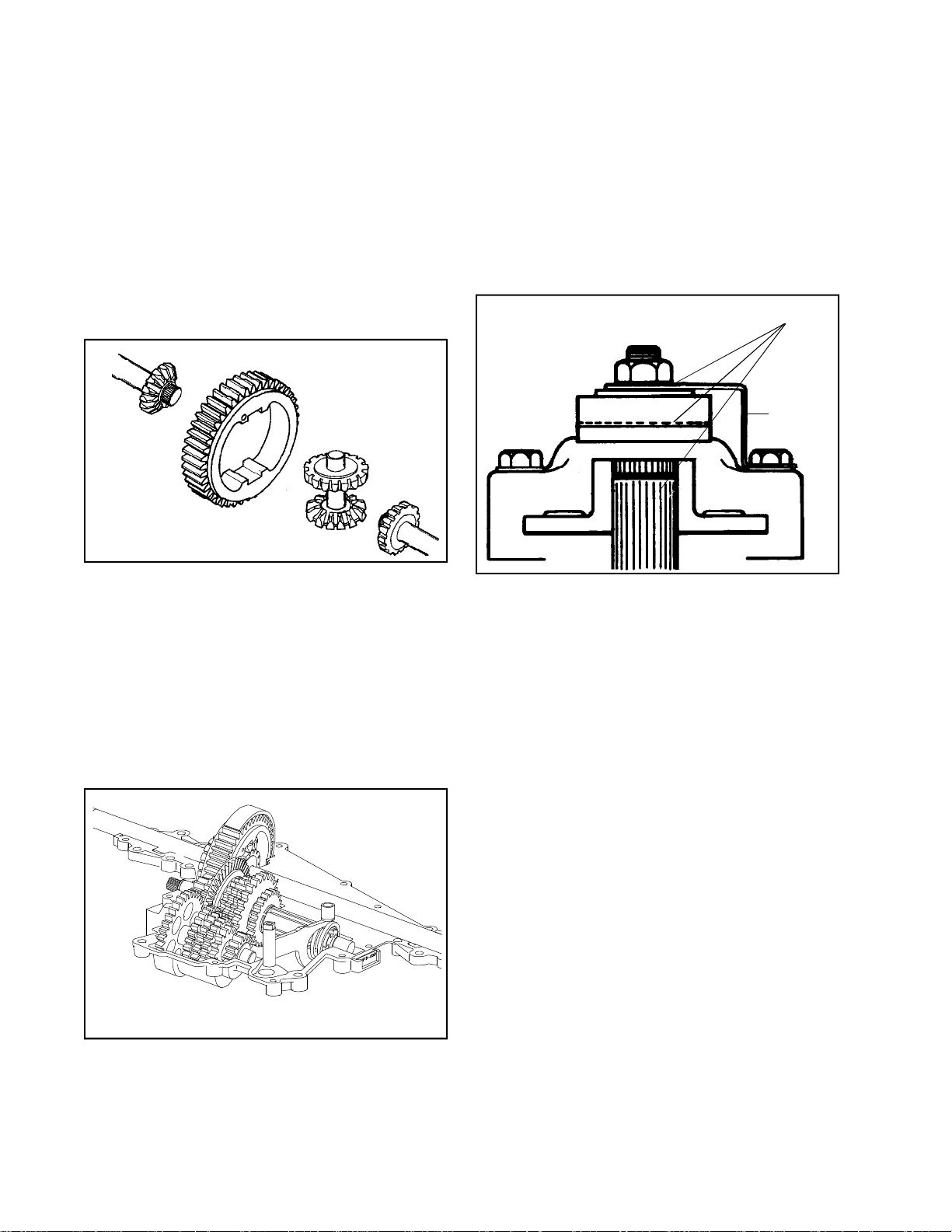
The two assembled shafts can now be placed
Main Menu
Main Menu
in to the transaxle case. If model has the reverse
idler held in place by the case insert reverse
idler into the case prior to inserting shafts.
NOTE: Dependent on the rotation of the
countershaft gears the reverse idler assembly
will be located either above the reverse gears
and held in place by bosses in the cover or
below the reverse gears and held in place by
bosses in the case. The reverse idler assembly
will always be located against the thrust of the
countershaft reverse gear.
Make sure that the tab on the bronze bushing
is located into the recess provided in the case.
Clean the mating surfaces of case and cover;
place a continuous thin bead of sealant all
around the seam. Use Loctite Gasket Eliminator
#515 , Tecumseh part number 510334 or the
Loctite Silicone RTV 598, Tecumseh part number
788093.
8. Guide cover over shift rod and position onto
case. Install the cover cap screws and torque
90-100 inch pounds. Install the neutral start
sensing switch if applicable. Replace “O” ring
on shift rod.
Check for binding by turning input shaft.
APPLY LUBRIPLATE
BRAKE
BRACKET
NOTE: The differential must be assembled out
of the case and then placed in the case. Apply
Bentonite grease to axle contact areas of case.
6. Place the center shaft with the bevel pinion
gears into the bull gear of the differential. Center
the bevel gear of one axle with the pinion gears
of the differential. Center the bevel gear of the
other axle to the pinion gears of the differential.
Pick up the entire unit and place it in the case
as an assembly. Reposition the rubber seals
on the ends of the axles in their bosses. (If
damaged or old replace them).
9. Prior to installing the brake assembly, apply a
light film of lubriplate to the inside of lever portion
which contact pins, also to outside of lever
which contacts flat washer and between shaft
O.D. and bore of brake disc. Brake pads and
brake disc must be free of grease and oil. Install
brake assembly.
Install transaxle on equipment. Adjust brake
linkage to disengage when clutch is engaged.
Brake and linkages may vary. Consult equipment
owner’s manual.
NOTE: If adjusted incorrectly, the brake will
do one of two things:
a. It will not brake (stop) the vehicle when
the brake is applied, or,
b. If adjusted too tightly, a drag or continued
braking effect will be evident until the brake
wears out.
48
7. Install the shifter assembly, bearing strap and
reverse idler assembly (if applicable). Pack the
transaxle with the remaining Bentonite grease
(10 ounces total). Replace index spring and
ball.
Page 51
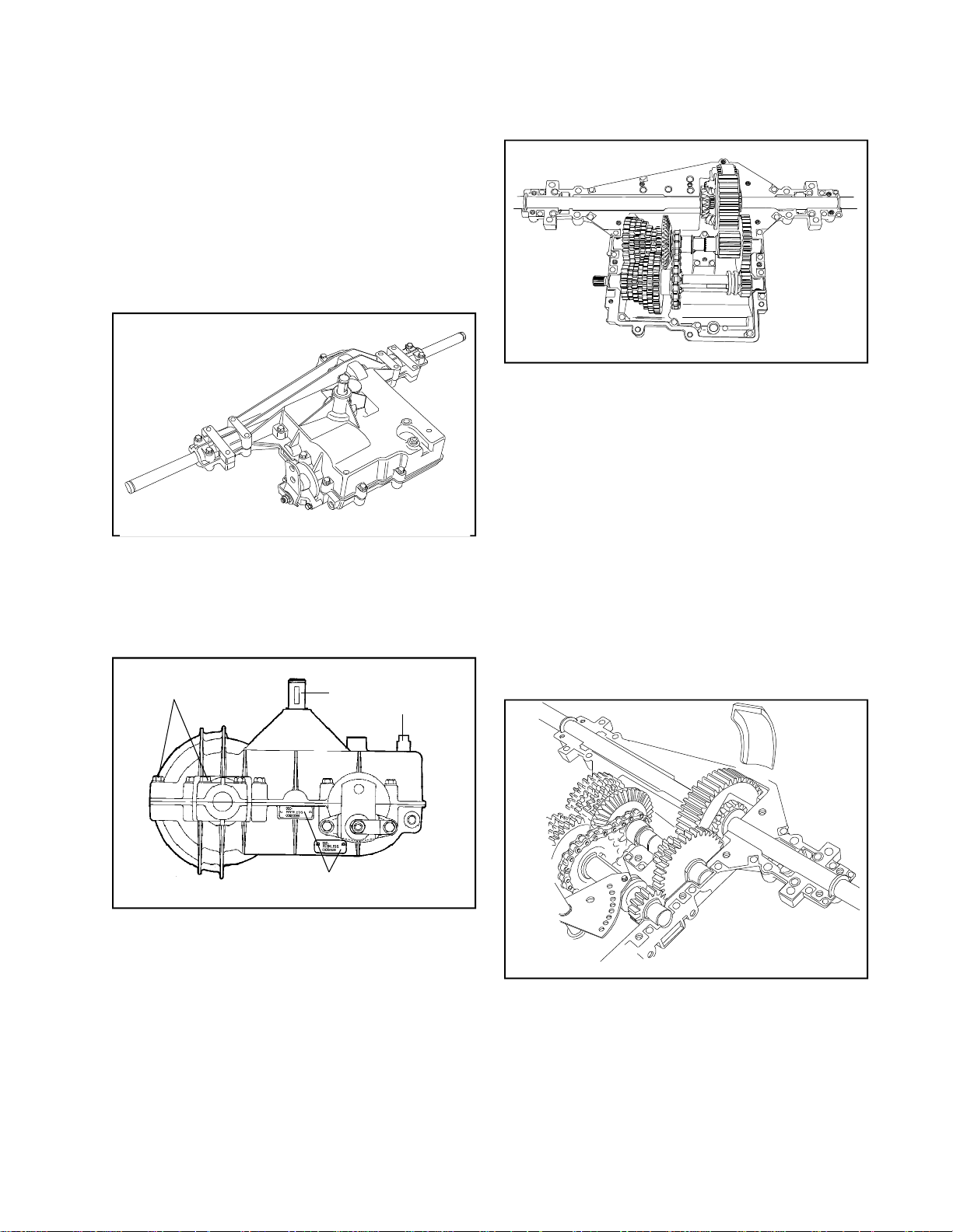
SECTION 8. 920 SERIES
Main Menu
Main Menu
CAUTION:
TO AVOID PREMATURE TRANSAXLE FAILURE,
DECLUTCHING IS REQUIRED WHEN SHIFTING
FROM NEUTRAL TO FIRST OR REVERSE; FROM
ANY FORWARD TO REVERSE GEAR OR WHEN
OPERATING EQUIPMENT ON A HILL OR UNDER
HEAVY LOAD.
NOTE: Due to the many variations of equipment braking
systems, adjustment and repair to the components
and linkages are not considered warranty.
A. GENERAL
The 920 series transaxle is very similar to the 900
series. The 920 series will be available in 5, 6, or 7
speeds forward and 1 speed reverse. The 7 speed
transaxle will be shown in the teardown portion of
this manual.
COVER CASE HEX
SCREWS
INPUT
SHAFT
SHIFT ROD
D. DISASSEMBLY
1. Remove the hex head screws that hold the
cover to the case.
2. Push down on the shift lever rod while pulling
cover off of the case. The shifting lever may
temporarily remain in the case. Lift off cover.
3. Remove the two brake bracket screws and
remove brake assembly.
4. Remove the grease from the unit as the parts
are removed. Prior to removal of gear shaft
assemblies from the case, the shifter fan may
be removed. Note the position of the parts before
removal. Some parts may fall off the shafts
upon removal.
NOTE: BENTONITE GREASE MAY STAIN
CLOTHES. CARE SHOULD BE USED WHEN
HANDLING.
A
B
ID TAG
B. IDENTIFICATION
This unit contains an aluminum tag at location A
or B, showing the model number.
C. STEPS TO TAKE BEFORE DISASSEMBLY.
1. Clean the outside surface of the transaxle.
2. Position the shift lever in the neutral position.
3. Remove the set screw, spring and index ball.
4. If installed (O.E.M. option), remove the neutral
start switch.
5. Remove the top bearing block on the bull gear
of the differential. Remove the bull gear, bevel
pinion gears with center shaft and the axles.
49
Page 52
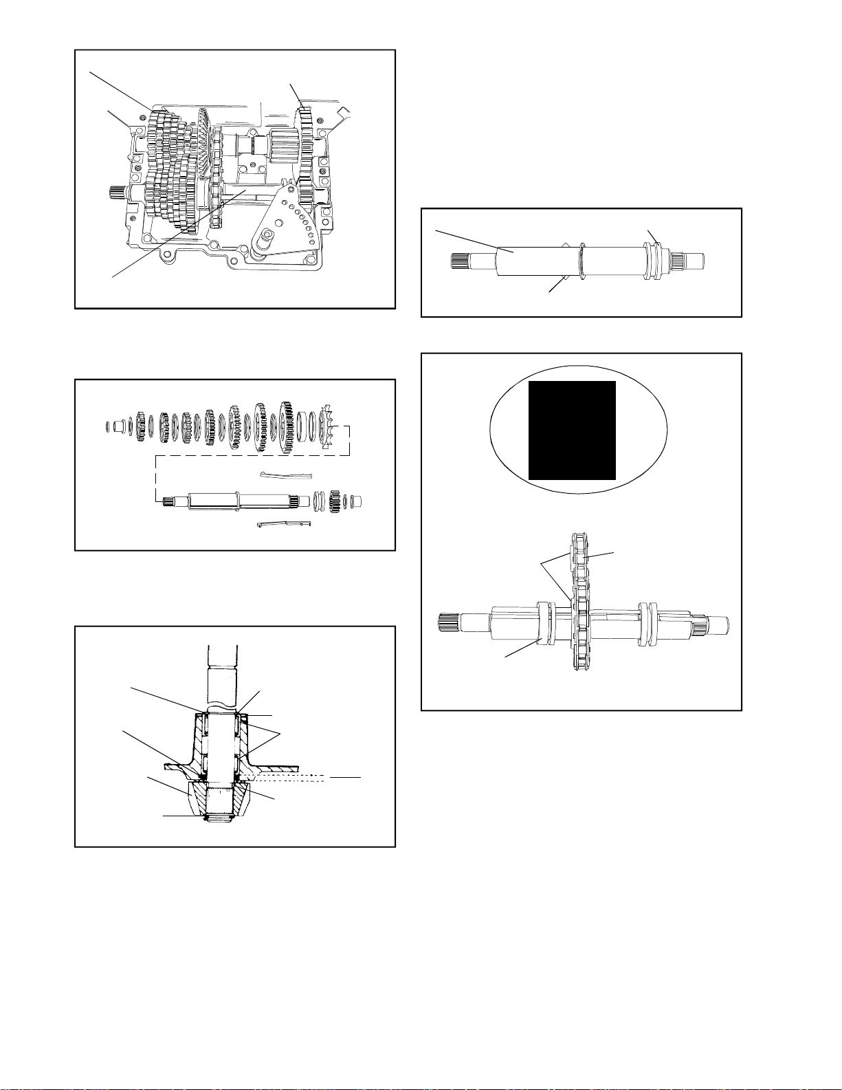
COUNTERSHAFT ASSEMBLY
Main Menu
Main Menu
OUTPUT SHAFT
ASSEMBLY
NOTE: Needle bearings are lubricated with E.P.
grease. DO NOT USE BENTONITE on needle
bearings. For maximum gear train life use only
Bentonite grease on all shafts and gears,
Tecumseh part number 788067B.
E. REASSEMBLY
1. Apply grease between the bearings in the cover
and install the input shaft, square cut seal,
thrust washers, bevel gear and snap ring.
SHIFTER/BRAKE SHAFT ASSEMBLY
6. There are 3 shaft assemblies in this transaxle;
the output shaft, the countershaft, and the
shifter/brake shaft assembly. Remove these
assemblies as complete as possible from the
case.
7. As these assemblies are taken apart, lay the
parts out in a systematic order. This will help
to make reassembly easier and inspection of
all parts possible. Clean each part of grease
as the parts are laid out.
SHIFTER/BRAKE SHAFT
KEYS
SHIFT COLLAR
2. Grease both keyways and slide keys and collar
on shifter/brake shaft.
SPROCKET
COLLARS
LARGE
INNER
DIAMETERS
FACE EACH
OTHER
LARGER
RADIUS
SPACER
TOWARD
SHIFT KEYS
REVERSE CHAIN AND
SPROCKETS
NEEDLE BEARING
FLUSH WITH
HOUSING
SQUARE CUT
"O" RING
BEVEL GEAR
RETAINING RING
RETAINING RING
WASHER
NEEDLE
BEARINGS
THRUST
WASHER
INPUT
SHAFT
.135"
.150"
8. The input shaft can also be removed and
inspected or serviced. Remove the snap ring
on the bevel gear and pull the shaft through
the case. The square cut “O” ring must be
replaced if the shaft is removed.
Tool part No. 670251, is used for removal and
installation of needle bearings for the input shaft.
The needle bearing on the inboard side is
installed .135 .150” below flush.
NEUTRAL
SPACER
3. To assemble this transaxle the countershaft
and the shifter/brake shaft should be assembled
at the same time. Start by placing the reverse
chain over the reverse sprockets. Make sure
that the collars on the sprockets are on the
same side of the chain and install the larger
sprocket onto the shifter/brake shaft with the
collar away from the shifting keys.
Next place the neutral spacers onto the shifter/
brake shaft with larger inner diameter sides
facing together, and the spacer with the largest
inner diameter radius toward the shift keys.
Push the shifting keys through the reverse
sprocket and the first neutral spacer, pull the
neutral spacers and the reverse sprocket up
against the shoulder of the shifter/brake shaft.
NOTE: Their have been a few 900 models built
with identical neutral collar halfs. These can
be installed either direction.
50
Page 53
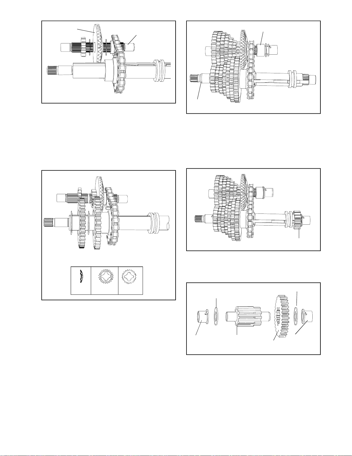
BEVEL GEAR
Main Menu
Main Menu
COUNTERSHAFT
*4. Insert the countershaft into the smaller reverse
sprocket. Insert a thin thrust washer next to
the sprocket (collar side) and then install the
large bevel gear, with the bevel towards the
reverse sprocket. Place another thin thrust
washer on the back side of the bevel gear.
NOTE: As all the gears are placed back into
the assembly, each should be packed with
Bentonite grease.
SPACER
"O" RING
6. Place the spacer on the countershaft next to
the reverse sprocket. Then place a thrust washer
on each end of the countershaft and insert the
bronze bushings.
Place the large washer on the end of the shifter/
brake shaft, the bronze bushing and the “O”
ring.
SHIFTING
WASHER
CUT OUT SIDE
FLAT SIDE
5. Build the gears on the countershaft and shifter/
brake shaft alternately, meshing each gear with
it’s mating gear on the other shaft. The first
gear on the shifter/brake shaft would be the
largest of the shifting gears. Place this gear
next to the neutral collar with the flat side of
the gear next to the collar.
Then place a shifting washer onto the shifter/
brake shaft with the rounded edge towards the
shifting keys. Continue this procedure until all
the gears on both shafts have been added.
NOTE: It is not only important that gears match
up diameter-wise, but must match up according
to thickness.
SPUR GEAR
7. Place the spur gear onto the splines on the
other end of the shifter/brake shaft. The thin
washer, bushing, and “O” ring conclude the
assembly of these 2 shafts.
WASHER
WASHER
BUSHING
OUTPUT
PINION
OUTPUT
GEAR
BUSHING
8. Place the output gear on the stepped end of
the output pinion. Place the thrust washers on
each end and then the bronze bushings. Install
these 3 shaft assemblies back into the case.
Make sure that the tabs of all the bushings are
in their “V” notches in the case.
*Models with the large bevel gear turned 180o and
placed on the opposite side of the reverse sprocket
will be explained under assembly variations subsection F.
51
Page 54
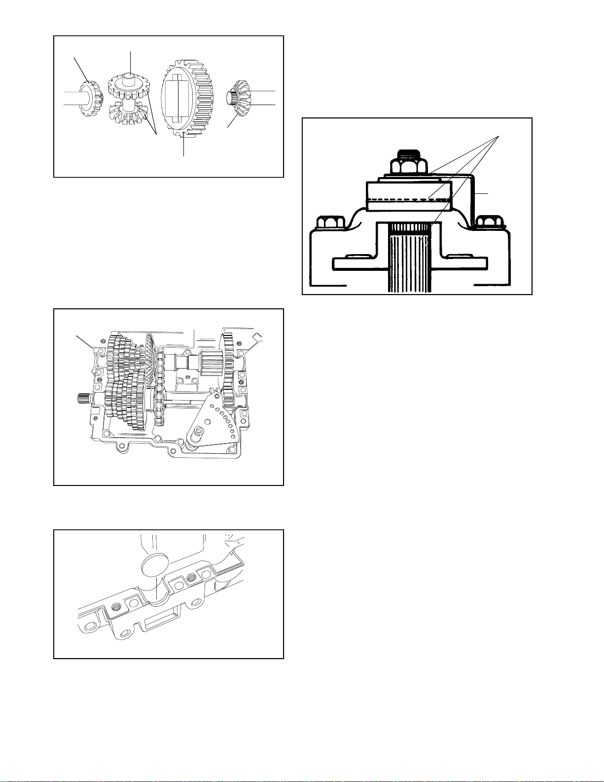
BEVEL GEAR
Main Menu
Main Menu
CENTER SHAFT
Install the cover screws and torque to 90-100
inch pounds.
Replace index ball, spring and set screw and
turn set screw one (1) turn below flush. Install
the neutral start sensing switch if applicable.
Check for binding by turning input shaft.
BEVEL PINION
GEARS
BULL GEAR
BEVEL GEAR
NOTE: The differential must be assembled out
of the case and then placed in the case. Apply
Bentonite grease to axle contact areas of case.
9. Place the center shaft with the bevel pinion
gears into the bull gear of the differential. Center
the bevel gear on the longest axle with the pinion
gears of the differential. Center the bevel gear
on the other axle to the other side. Pick up the
entire unit and place it in the case as an
assembly. Reposition the rubber seals on the
ends of the axles in their bosses. (If damaged
or old replace them).
APPLY LUBRIPLATE
BRAKE
BRACKET
12. Prior to installing the brake assembly, apply a
light film of lubriplate to the inside of lever portion
which contact pins, also to outside of lever
which contacts flat washer and between shaft
O.D. and bore of brake disc. Brake pads and
brake disc must be free of grease and oil. Install
brake assembly.
Install transaxle on equipment. Adjust brake
linkage to disengage when clutch is engaged.
Brake and linkages may vary. Consult equipment
owner’s manual.
10. Install the shifter assembly and bearing strap,
pack the transaxle with the remaining Bentonite
grease (30 ounces total). Apply grease to top
of shift fan.
11. To seal the case and cover at the end of the
shifter/brake shaft, a flat plug is placed there
(end opposite the brake assembly). Clean the
mating surfaces of case and cover; place a
continuous thin bead of sealant all around the
seam. Use Loctite Gasket Eliminator #515 ,
Tecumseh part number 510334 or the Loctite
Silicone RTV 598, Tecumseh part number
788093.
52
NOTE: If adjusted incorrectly, the brake will
do one of two things:
a. It will not brake (stop) the vehicle when
the brake is applied, or,
b. If adjusted too tightly, a drag or continued
braking effect will be evident until the brake
wears out.
*F.ASSEMBLY VARIATIONS
On models which are driven from the opposite side
of the input bevel gear the following changes take
place. A slightly thicker large bevel gear is placed
on the countershaft with the bevel facing the spur
gears and in the previous location of the spacer.
The thickness of the gear eliminates the need for
the washers on each side of the large bevel gear.
The reverse chain and sprocket is also turned 180o,
which places sprocket collars away from shifting
gears and spur gears. The spacer is then placed
in the previous location of the large bevel gear next
to the reverse sprocket.
Page 55
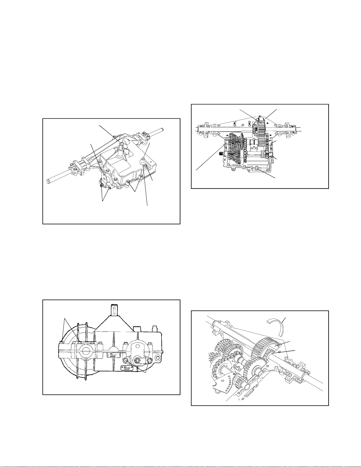
SECTION 9. 930 SERIES
Main Menu
Main Menu
CAUTION:
TO AVOID PREMATURE TRANSAXLE FAILURE,
DECLUTCHING IS REQUIRED WHEN SHIFTING
FROM NEUTRAL TO FIRST OR REVERSE; FROM
ANY FORWARD TO REVERSE GEAR OR WHEN
OPERATING EQUIPMENT ON A HILL OR UNDER
HEAVY LOAD.
NOTE: Due to the many variations of equipment braking
systems, adjustment and repair to the components
and linkages are not considered warranty.
INPUT SHAFT
IDENTIFICATION TAG
BRAKE BRACKET SCREWS
(BRAKE CAN BE ON RIGHT
OR ON LEFT SIDE)
COVER/CASE
HEX SCREWS
NEUTRAL START SWITCH
LOCATION (OPTIONAL)
INDEX BALL,
SPRING AND
SET SCREW
SHIFT ROD
A. GENERAL
The 930 series transaxle is very similar to the 920
series. The 930 series will be available in 3 through
7 speeds forward and 1 speed reverse. The model
pictured throughout this section is the most popular
type, there are models which operate in the opposite
direction without changing the input location.
Throughout this section an asterik (*) will direct
the reader to the end of the section where the
differences between these models will be explained.
COVER CASE
HEX
SCREWS
C. STEPS TO TAKE BEFORE DISASSEMBLY.
1. Clean the outside surface of the transaxle.
2. Position the shift lever in the neutral position.
3. Remove the set screw, spring and index ball.
4. If installed (O.E.M. option), remove the neutral
start switch.
D. DISASSEMBLY
DIFFERENTIAL
COUNTERSHAFT
ASSEMBLY
BEARING STRAP
OUTPUT SHAFT
ASSEMBLY
SHIFTER/BRAKE
SHAFT ASSEMBLY
SHIFTER ASSEMBLY
LOCATION
1. Remove the hex head screws that hold the
cover to the case.
2. Push down on the shift lever rod while pulling
cover off of the case. The shifting lever may
temporarily remain in the case. Lift off cover.
3. Remove the two brake bracket screws and
remove brake assembly.
4. Remove the grease from the unit as the parts
are removed. Prior to removal of gear shaft
assemblies from the case, the shifter fan may
be removed. Note the position of the parts before
removal. Some parts may fall off the shafts
upon removal.
NOTE: BENTONITE GREASE MAY STAIN
CLOTHES. CARE SHOULD BE USED WHEN
HANDLING.
BEARING STRAP
BRAKE
BRACKET
SCREWS
B. IDENTIFICATION
This unit has an aluminum tag showing the model
number, make sure tag is not misplaced during
disassembly.
DIFFERENTIAL
BULL GEAR
AXLE BEVEL
GEAR
5. Remove the bearing strap on the bull gear of
the differential. Some models do not use a
bearing strap. Remove the bull gear, bevel pinion
gears with center shaft and the axles. Grasp
the axle bevel gears between your thumb and
fingers, hold together while lifting differential
from case.
53
Page 56
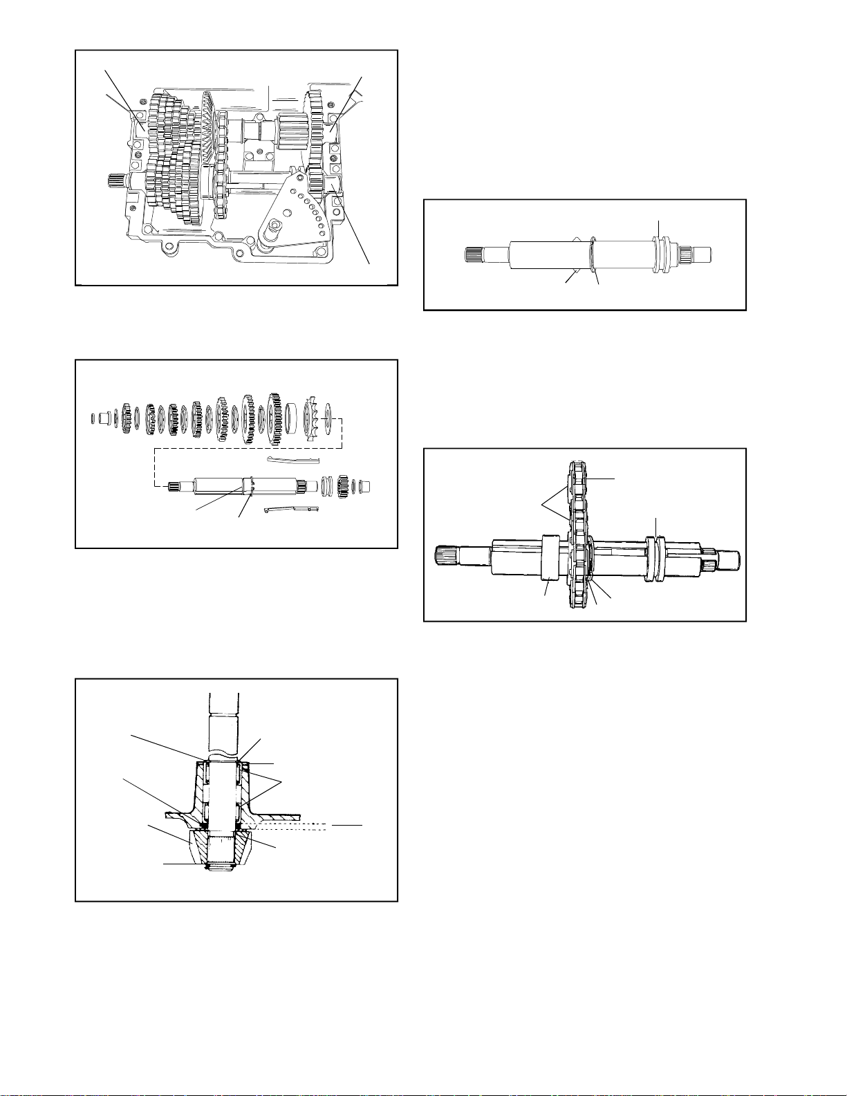
COUNTERSHAFT ASSEMBLY
Main Menu
Main Menu
OUTPUT SHAFT
ASSEMBLY
Tool part No. 670251, is used for removal and
installation of needle bearings for the input shaft.
The needle bearing on the inboard side is
installed .135 .150” below flush.
E. REASSEMBLY
1. Apply grease between the bearings in the cover
and install the input shaft, square cut seal,
thrust washers, bevel gear and snap ring.
SHIFTER/BRAKE SHAFT ASSEMBLY
6. There are 3 shaft assemblies in this transaxle;
the output shaft, the countershaft, and the
shifter/brake shaft assembly. Remove these
assemblies as complete as possible from the
case.
SNAP RING GROOVE
SNAP RING
7. As these assemblies are taken apart, lay the
parts out in a systematic order. This will help
to make reassembly easier and inspection of
all parts possible. Clean each part of grease
as the parts are laid out. To remove keys from
the shifter/brake shaft you must first remove
the large snap ring from the snap ring groove.
Be careful not to stretch or twist snap ring, it
is not necessary to remove snap ring from shaft.
NEEDLE BEARING
FLUSH WITH
HOUSING
SQUARE CUT
"O" RING
BEVEL GEAR
RETAINING RING
RETAINING RING
WASHER
NEEDLE
BEARINGS
THRUST
WASHER
INPUT
SHAFT
.135"
.150"
SHIFTER/BRAKE SHAFT
KEYS (2 OR 4) SNAP RING
SHIFT COLLAR
2. Grease all keyways and slide keys and collar
onto the shifter/brake shaft. (There are both 2
and 4 key models). Place large snap ring back
into the snap ring groove. On models which
have a inner diameter recess cut into one side
of the shift collar, the recess side must face
towards the gears and snap ring for proper gear
selection.
REVERSE CHAIN AND
SPROCKETS
SPROCKET COLLARS
NEUTRAL SPACER
SNAP RING
WASHER
SHIFT
COLLAR
* 3. To assemble this transaxle the countershaft
and the shifter/brake shaft should be assembled
at the same time. Start by placing the reverse
chain over the reverse sprockets. Make sure
that the collars on the sprockets are on the
same side of the chain. Install a large washer
onto the shifter/brake shaft next to the snap
ring and then the large sprocket with the collar
away from the shifting keys. Push the shifting
keys through the reverse sprocket and push
the neutral spacer over the end of the keys
and pull the neutral spacer and reverse sprocket
up against the snap ring on the shifter/brake
shaft.
54
8. The input shaft can also be removed and
inspected or serviced. Remove the snap ring
on the bevel gear and pull the shaft through
the case. The square cut “O” ring must be
replaced if the shaft is removed.
NOTE: Needle bearings are lubricated with E.P.
grease. DO NOT USE BENTONITE on needle
bearings.For maximum gear train life use only
Bentonite grease on all shafts and gears,
Tecumseh part number 788067B.
Page 57
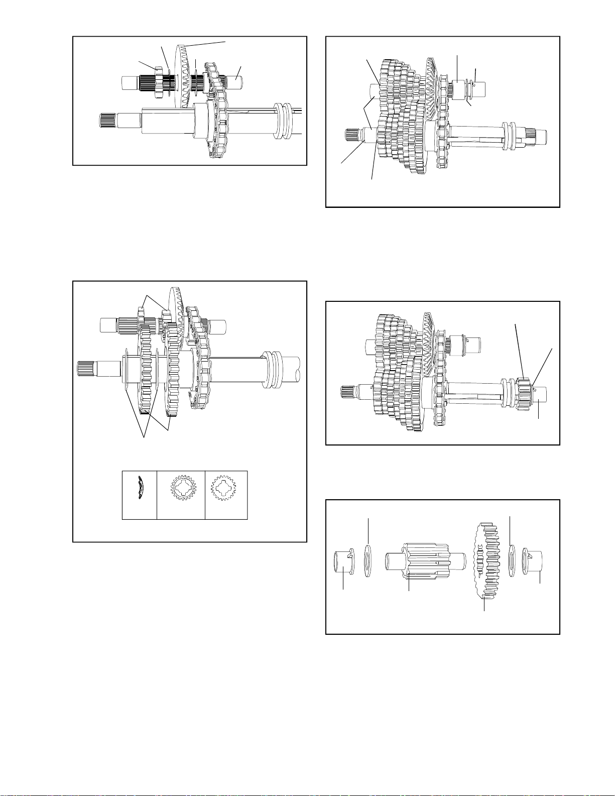
WASHER
Main Menu
Main Menu
SPUR GEAR
WASHER
BEVEL GEAR
COUNTERSHAFT
THRUST
WASHER
SPACER
BUSHING
*4. Insert the countershaft into the smaller reverse
sprocket. Insert a thin thrust washer next to
the sprocket (collar side) and then install the
large bevel gear, with the bevel towards the
reverse sprocket. Place another thin thrust
washer on the back side of the bevel gear.
NOTE: As all the gears are placed back into
the assembly, each should be packed with
Bentonite grease.
SPUR GEARS
BUSHING
"O" RING
WASHER
THRUST WASHER
*6. Place the spacer on the countershaft next to
the reverse sprocket. Then place a thrust washer
on each end of the countershaft and insert the
bronze bushings.
Place the large washer on the end of the shifter/
brake shaft, the bronze bushing and the “O”
ring.
SPUR GEAR
WASHER
SHIFT WASHERS
SHIFTING
WASHER
SHIFT GEARS
CUT OUT SIDE
FLAT SIDE
5. Build the gears on the countershaft and shifter/
brake shaft alternately, meshing each gear with
its mating gear on the other shaft. The first
gear on the shifter/brake shaft would be the
largest of the shifting gears. Place this gear
next to the neutral spacer with the flat side of
the gear next to the spacer.
Then place a shifting washer onto the shifter/
brake shaft with the rounded edge towards the
shifting keys. Continue this procedure until all
the gears on both shafts have been added.
NOTE: It is not only important that gears match
up diameter-wise, but must match up according
to thickness.
BUSHING
7. Place the spur gear onto the splines on the
other end of the shifter/brake shaft. The thin
washer and bushing conclude the assembly of
these 2 shafts.
WASHER
BUSHING
OUTPUT
PINION
WASHER
BUSHING
OUTPUT GEAR
8. Place the output gear on the stepped end of
the output pinion. Place the thrust washers on
each end and then the bronze bushings. Install
these 3 shaft assemblies back into the case.
Make sure that the tabs of all the bushings are
in their “V” notches in the case.
55
Page 58
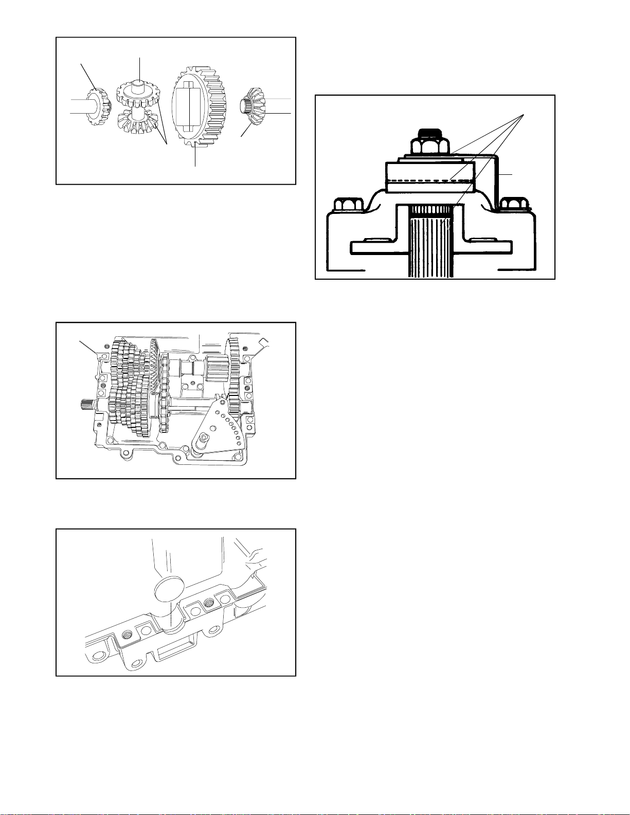
BEVEL GEAR
Main Menu
Main Menu
CENTER SHAFT
Replace index ball, spring and set screw and
turn set screw one (1) turn below flush. Install
the neutral start sensing switch if applicable.
Check for binding by turning input shaft.
APPLY LUBRIPLATE
BEVEL PINION
GEARS
BULL GEAR
BEVEL GEAR
NOTE: The differential must be assembled out
of the case and then placed in the case. Apply
Bentonite grease to axle contact areas of case.
9. Place the center shaft with the bevel pinion
gears into the bull gear of the differential. Center
the bevel gear on the longest axle with the pinion
gears of the differential. Center the bevel gear
on the other axle to the other side. Pick up the
entire unit and place it in the case as an
assembly. Reposition the rubber seals on the
ends of the axles in their bosses. (If damaged
or old replace them).
BRAKE
BRACKET
12. Prior to installing the brake assembly, apply a
light film of lubriplate to the inside of lever portion
which contact pins, also to outside of lever
which contacts flat washer and between shaft
O.D. and bore of brake disc. Brake pads and
brake disc must be free of grease and oil. Install
brake assembly.
Install transaxle on equipment. Adjust brake
linkage to disengage when clutch is engaged.
Brake and linkages may vary. Consult equipment
owner’s manual.
NOTE: If adjusted incorrectly, the brake will
do one of two things:
10. Install the shifter assembly and bearing strap,
pack the transaxle with the remaining Bentonite
grease (30 ounces total). Apply grease to top
of shift fan.
11. To seal the case and cover at the end of the
shifter/brake shaft, a flat plug is placed there
(end opposite the brake assembly). Clean the
mating surfaces of case and cover; place a
continuous thin bead of sealant all around the
seam. Use Loctite Gasket Eliminator #515 ,
Tecumseh part number 510334 or the Loctite
Silicone RTV 598, Tecumseh part number
788093. Install cover screws and torque to 90100 inch pounds.
56
a. It will not brake (stop) the vehicle when
the brake is applied, or,
b. If adjusted too tightly, a drag or continued
braking effect will be evident until the brake
wears out.
*F.ASSEMBLY VARIATIONS
On models which are driven from the opposite side
of the input bevel gear the following changes take
place. A slightly thicker large bevel gear is placed
on the countershaft with the bevel facing the spur
gears and in the previous location of the spacer.
The thickness of the gear eliminates the need for
the washers on each side of the large bevel gear,
which places the sprocket collars away from the
shifting gears and spur gears. The reverse chain
and sprocket is also turned 180o. The spacer is
then placed in the previous location of the large
bevel gear next to the reverse sprocket.
Page 59
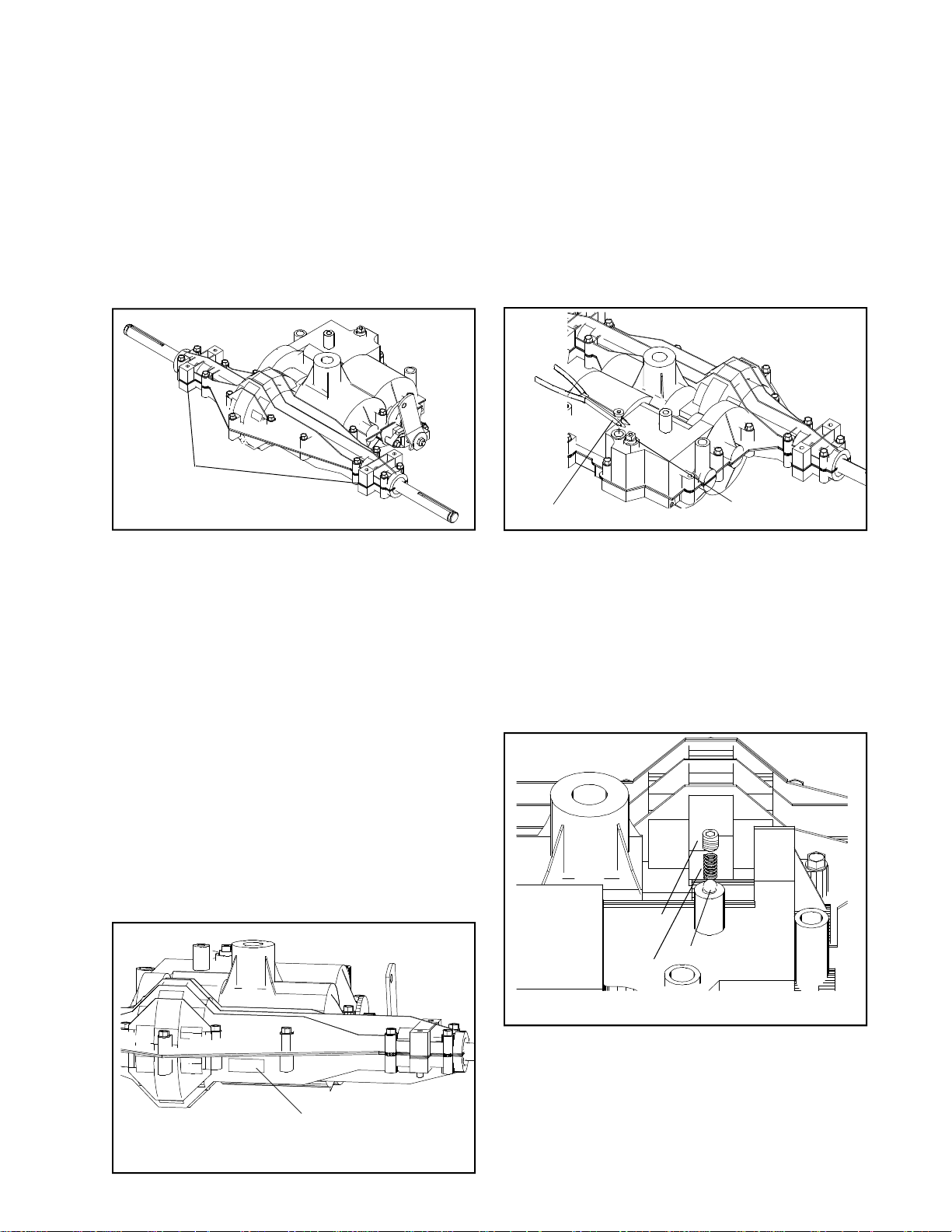
SECTION 10. MST200
Main Menu
Main Menu
CAUTION:
TO AVOID PREMATURE TRANSAXLE FAILURE,
DECLUTCHING IS REQUIRED WHEN SHIFTING
FROM NEUTRAL TO FIRST OR REVERSE; FROM
ANY FORWARD TO REVERSE GEAR OR WHEN
OPERATING EQUIPMENT ON A HILL OR UNDER
HEAVY LOAD.
NOTE: Due to many variations of the equipment braking
systems, adjustment and repair to the components
and linkages are not considered warranty.
CUSTOMER
MOUNT POINTS
(PRY POINT)
A REMOVE FILL PLUG
A. GENERAL
The MST (Manual Shift Transaxle) 200 is a sealed
unit which uses 16 oz. of 80W90 gear lube (part
#730229A). The MST series is available with up
to 6 speeds forward and one reverse. It has a
sculptured case and cover. Its unique gear design
system uses the input gear to drive both the forward
and reverse motion. It also eliminates the recess
previously found on shifter brake shaft spur gears.
The thrust washers on all transaxles are used to
protect stationary surfaces from rotating surfaces.
To determine the location of the thrust washer,
check its inside diameter and compare it to the
outside diameter of the shaft. If the fit is loose, it
is out of position. The flat washer used on the
shifter shaft (brake end) must have a diameter
large enough to stop the keys from going past
the end of the gear slots.
B. IDENTIFICATION
The MST has a decal placed at the rear of the
unit and to the right of the differential gear section.
This makes it easily visible without having to
remove any obstructions to view it. (See Illustration
B).
C. STEPS TO TAKE BEFORE DISASSEMBLY.
1. Clean the outside surface of the transaxle.
2. Position the shift lever in the neutral position.
SQUARE CUT O-RING
AND PUSH NUT
C
3. Remove the oil drain / fill plug located on top
of the unit. This can be done by using a needle
nose pliers to pull the plug out. Drain all of
the oil from the unit. (See Illustration C)
4. Remove the neutral start switch, if installed
(O.E.M. option).
5. Remove the push nut (if equipped) and square
cut "O" ring, from the top of the shift fork
shaft. (See Illustration C).
DETENT
SCREW
BALL
SPRING
D
6. Remove the set screw, spring and index ball
(See Illustration D).
IDENTIFICATION TAG
B
57
Page 60
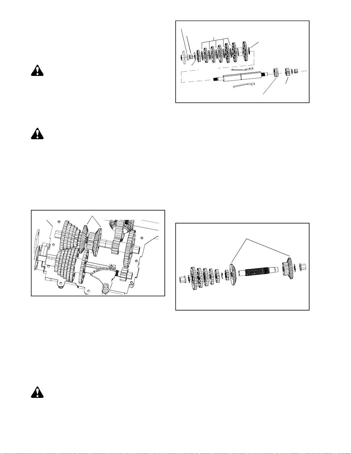
D. DISASSEMBLY.
Main Menu
Main Menu
1. Remove the self-tapping hex head screws that
hold the cover to the case and the two center
screws located on the bottom (case side) of
the transaxle.
SEAL
BUSHING
SHIFTER WASHERS
THRUST WASHER
CAUTION: With the new sealant between the
case and cover, it may be necessary to pry
them apart. If you find this necessary ONLY
PRY IN THE MOUNTING FOOT AREA. See
Illustration A, page 57.
2. With a rubber or leather mallet tap down on
the shift lever rod while removing the cover
from the case.
If rust has occurred on the shaft, remove it
with emery cloth before removing the shaft to
prevent damage.
3. Remove the two brake bracket screws and
remove the brake assembly.
4. Remove the differential ring gear, and bevel
pinion gears with the center shaft drive pin
and the axles. Grasp the axle bevel gears
between your thumb and fingers. Hold the entire
assembly together while lifting the differential
from the case.
NOTE A
THRUST WASHER
SPUR GEAR
NOTE: INSIDE RECESS FACES KEYS
7. To disassemble the shifter/brake shaft, start
on the spur gear side. Remove the oil seal,
the bronze bushing and thrust washer. Remove
all of the shifter spur gears (or spacers if used)
and shift washers. Remove the neutral collar,
reverse gear and thrust washer. On the output
side of the shifter/brake shaft remove the
bronze bushing, thrust washer, and output spur
gear.
To remove the shift keys from the shifter/brake
shaft, you must first expand the large snap
ring from the snap ring groove. Be careful not
to stretch or twist the snap ring, it is not
necessary to remove the snap ring from the
shaft. Place the expanded snap ring onto the
shifter/brake shaft and slide the shift keys
and shift collar off the shifter/brake shaft.
5. There are 3 shaft assemblies in this transaxle.
The countershaft, shifter/brake shaft and output
shaft. Remove shifter fork assembly and then
remove these assemblies from the case.
NOTE: Before you begin disassembly, ask
the customer if the unit has been serviced
previously by a technician or perhaps himself.
They may have misassembled it.
6. As these assemblies are taken apart, lay the
parts out in a systematic order. This should
help to make the reassembly easier.
CAUTION: The keyways can be extremely
sharp use care in this area.
NOTE A
REVERSE FOR B INPUT
8. To disassemble the counter spur gear shaft,
remove the bushing, thrust washer and spur
gears (or spacers if used) the last spur gear
is held in place by a retaining ring. Remove
the retaining ring and slide the spur gear and
forward drive bevel gear off the splined end
of the shaft. The bushing, thrust washer and
reverse drive bevel gear can be removed from
the unsplined end of the shaft.
NOTE A: When a "B" input is used the input
bevel gears will be in opposite of
picture. The drive spline on this
shaft also moves.
58
Page 61
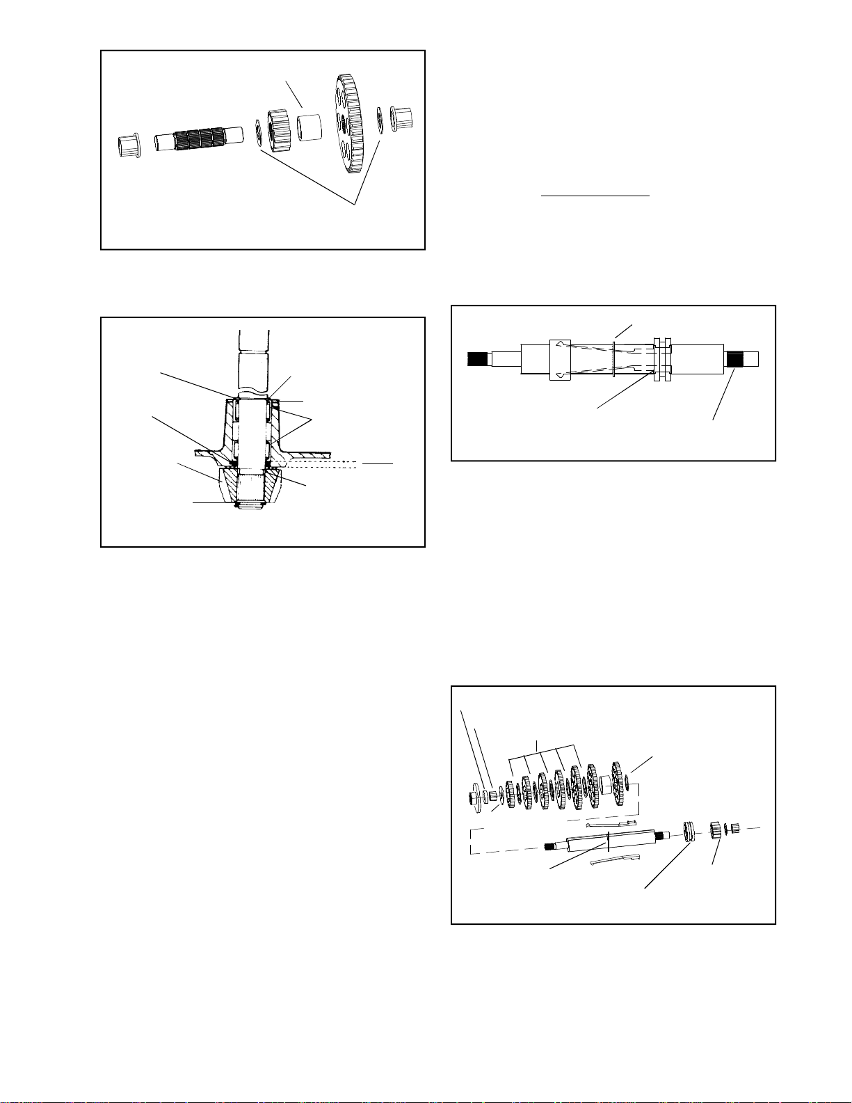
SPACER
Main Menu
Main Menu
THRUST WASHERS
ILLUSTRATION 1
9. To disassemble the output shaft, remove the
bushing, thrust washer, large output spur gear,
spacer, small output spur gear, thrust washer,
and bushing. (Illustration 1)
NEEDLE BEARING
FLUSH WITH
HOUSING
RETAINING RING
INPUT
SHAFT
E. REASSEMBLY
The tool, part number 670251 can also be used
for installation of the needle bearings for the input
shaft. The needle bearing on the inboard side is
installed .135" - .150" below flush. The top bearing
is installed flush to the casting.
1. Use an EP bearing grease and apply it to the
bearings in the cover. Place the seal into the
cover with the grooved side of seal visible
and facing the installer. Place the snap ring
and thrust washer on the input shaft and slide
the shaft through the cover and seal. Place
the square cut o-ring, thrust washer and input
bevel gear on the shaft on the inboard side
and secure them by placing a snap ring in
snap ring groove.
SNAP RING
OIL SEAL
BEVEL GEAR
RETAINING RING
ILLUSTRATION 2
WASHER
NEEDLE
BEARINGS
.135"
.150"
THRUST
WASHER
10. The input shaft can also be removed and
inspected or serviced. Remove the snap ring
and thrust washer on the input shaft, pull the
shaft through the cover. The oil seal located
on the inboard side of the cover should be
replaced when reassembled. Be sure to reinstall
the upper and lower thrust washers. (Illustration
2)
11. Tool part number 670251 is used for removal
of needle bearings for the input shaft.
12. After clean up of all parts, a complete inspection
should be done. Check for chipping or damage
to teeth, keys or the 4 key slots in the shifter
gears. You also should inspect the 2 keyways
in the shifter shaft for damage, chipping or
knicking. Worn or damaged parts must be
replaced.
RECESS IN KEY COLLAR
ILLUSTRATION 3
SPUR GEAR SPLINE
2. Next assemble the shifter brake shaft by placing
the shift keys in the keyway on the shaft with
the tip of the keys facing the shifter spur gear
side of the shaft. Extend the collar end of the
key slightly beyond shaft. Place the shift collar
in the notch provided on the shift key with the
inside diameter recess on the collar facing
toward the tips of the key. Place the notch
from the second key on the inside diameter
of the collar and position the key in the slot
on the shifter brake shaft. Slide the keys and
the collar onto the shaft under the snap ring.
Place the snap ring back into the groove on
the shaft. (Illustration 3)
SEAL
BUSHING
THRUST WASHER
SHIFTER WASHERS
THRUST WASHER
SNAP RING
NOTE: INSIDE RECESS FACES KEYS
ILLUSTRATION 4
SPUR GEAR
3. Place the plain large thrust washer over the
key tips on the spur gear side of the shaft
next to the snap ring. The sequence that follows
is reverse gear then the neutral collar and 1st
thru the amount of gears the unit is equipped
with up to 6 gears (largest to smallest). Between
each gear place a shift washer. Bevel facing
keys. (Illustration 4)
59
Page 62
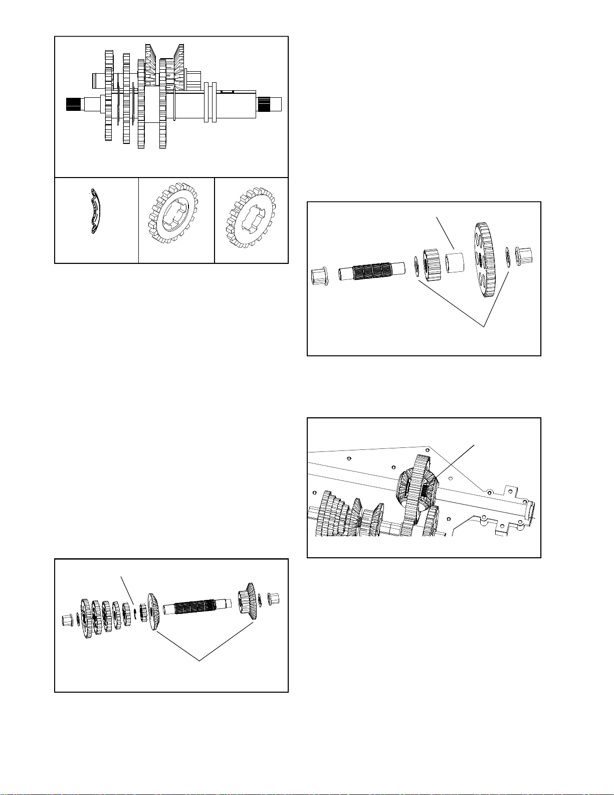
ILLUSTRATION 5
Main Menu
Main Menu
NEW STYLEOLD STYLESHIFTING WASHER
NOTE: Reverse and first gear do not have a
shift washer, the neutral collar compresses
the key here. Shift washers have one side
where the inside diameter is rounded, this
rounded edge must face the shift keys. The
shifter spur gears no longer have a recess on
one side of the gears and do not require that
the gear to be positioned in any particular
direction. Units that have less then six speeds
will use a spacer in place of a gear. When
this occurs it is not required to have a shift
washer between the spacer and the preceding
gear. (Illustration 5)
the forward input bevel gear and smallest spur
gear to be placed on the splined shaft with
the bevel facing the reverse drive gear. A
retaining ring is put on the shaft next to the
spur gear between the splined section to prevent
the bevel gears from spreading. (Illustration
6)
The countershaft is then completed by placing
the remaining spur gears on the shaft (smallest
to largest). If spacers are used they will be
placed between the final spur gear and the
washer and bushing. NOTE: The spur gears
on the countershaft can be installed in either
direction.
SPACER
THRUST WASHERS
ILLUSTRATION 7
5. The output shaft is completely splined and
consists of a bronze bushing, thrust washer,
a large output gear, spacer, small output gear,
thrust washer and bronze bushing. (Illustration
7)
When the final spur gear or spacer is in place,
a thrust washer is positioned on the shaft to
protect the case from the rotating gear. This
washer is slightly larger then the diameter of
the spacer and large enough to cover the inside
diameter of the key slot portion of the shifter
spur gear. Next place the bronze bushing and
the oil seal on the shaft (the open side of the
seal must face inward) this completes the spur
gear side of the shifter brake shaft. The output
side only requires the output spur gear, washer
and bushing.
RETAINING CLIP
REVERSE FOR "B" INPUT
ILLUSTRATION 6
4. To assemble the countershaft place the reverse
input bevel gear on the unsplined end of the
shaft with a washer and a bronze bushing to
complete the reverse drive side of the
countershaft. The forward drive side requires
DIFFERENTIAL
ASSEMBLY
ILLUSTRATION 8
6. To reassemble the differential, first inspect
the axle bevel gears for damage or wear. If it
is necessary to replace a gear, the mating
gears must also be replaced. The differential
must be assembled outside of the case and
placed into the case as an assembly
(Illustration 8).
Using seal protector (part # 670262A) place a
seal on each shaft with the open side facing
in. Hold the longest shaft with the bevel gear
and washer on it in your hand. Place the bull
gear and the bevel pinion gears and shaft ,
on top of the axle shaft and bevel gear. Center
the pinion gear shaft on the axle shaft and
place the short axle so that it is also centered
on the pinion shaft.
60
Page 63
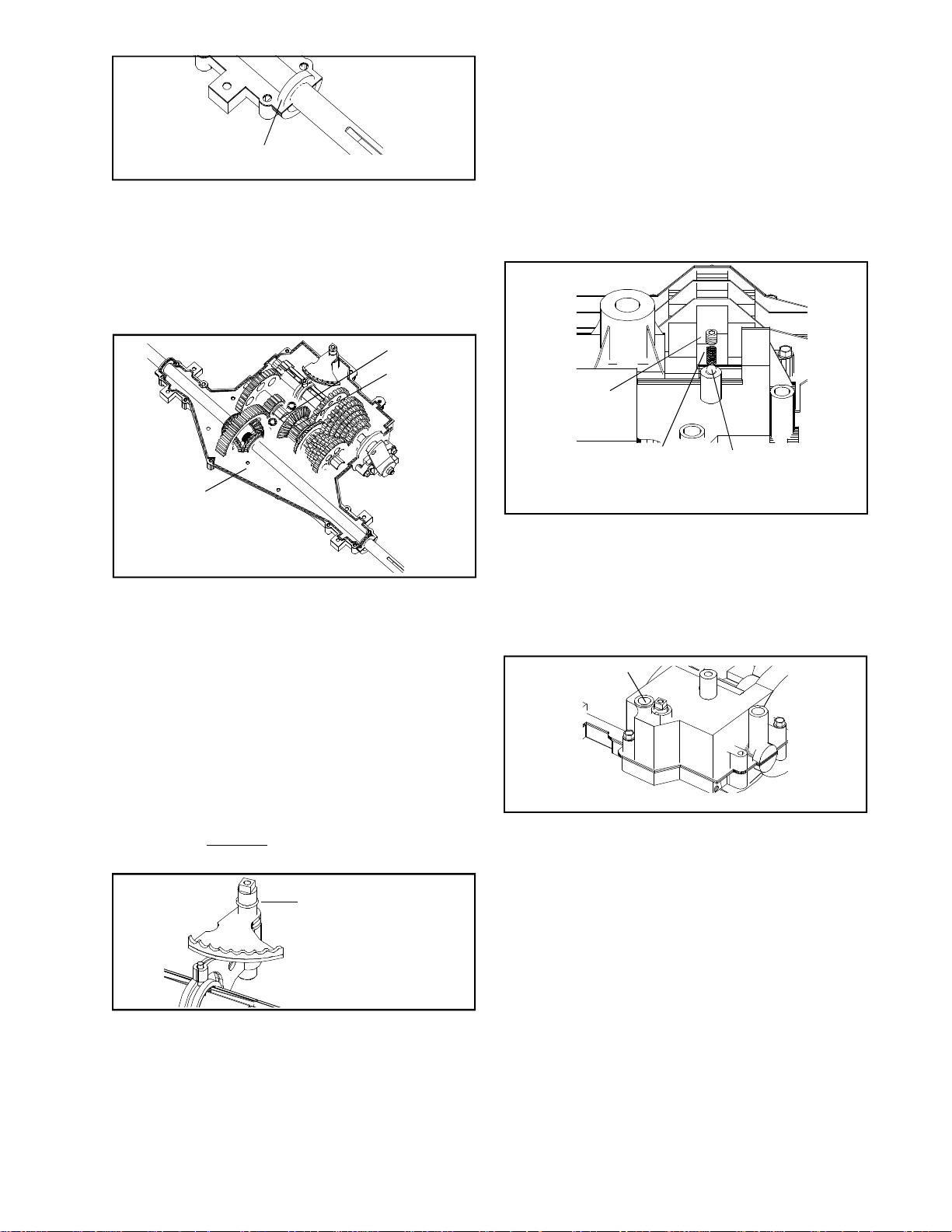
the "O" ring if needed. With the cover in position
Main Menu
Main Menu
over the shaft, place it onto the case and rotate
the input shaft to allow the gears to mesh
and drop the cover into place.
SEAL LOCATION
ILLUSTRATION 9
Pick up the entire assembly and place it into the case
positioning the seals in the seal pocket. When properly
installed the axle shaft should turn freely without any
binding. (Illustration 9)
NOTE: Before closing up the case make sure the case
and cover fit together evenly and all bushings are
properly installed. With the flat sides of the bushings
matching the pockets of the case and cover.
SEALANT
AROUND TWO
BOLTS FROM
BOTTOM OF
CASE
LOCTITE BEAD
INCLUDING AROUND
SEALS
ILLUSTRATION 10
7. To seal the case and cover. Clean the mating
surfaces and place a continuous thin bead (1/16")
of Loctite 598 Silicone RTV (part # 788093) around
the entire perimeter of the cover to prevent oil
from leaking INCLUDING CASE AND COVER SEAL
POCKETS. Caution must be used when locating
this bead so that oil passages that lead to the
axle shafts don't become blocked and prevent
lubrication in these critical areas. Don't forget
the two bottom bolts (Illustration 10).
Install the cover screws and torque them to
90-100 inch pounds. Replace the index ball,
spring and set screw. Turn the set screw down
to the flush position. Install the neutral start
sensing switch if applicable (Illustration 12).
NOTE: Do not forget to re-install the bottom
two bolts.
DETENT
SCREW
SPRING
NOTE: Detent screw must have pipe thread sealant applied to
prevent oil leakage.
ILLUSTRATION 12
BALL
9. Prior to installing the brake assembly apply a
light film of lubriplate to the inside of the lever
portion which contacts the pins. The outside
lever which contacts the flat washer and
between the shaft O.D. and bore of the brake
disc. Brake pads and the brake disc must be
free of grease and oil. Install the brake
assembly.
OIL FILL/DRAIN HOLE
NOTE: The axle and brake shaft seals on later
production MST's have been redesigned to
eliminate the need for sealant in the seal/bearing
pocket area. These new seals are identified by
external ribs that hold the seal in place and prevent
leakage. DO NOT put sealant in the seal/bearing
pockets with this new type seal.
"O" RING
ILLUSTRATION 11
Before placing the cover on the case, place
the shift rod and fork pins into the shift collar
and shaft into the boss in the case. Inspect
the shaft on the rod and fork for rust and burrs.
(Illustration 11)
8. Place a coating of grease on the shaft for easy
assembly and corrosion protection. Replace
ILLUSTRATION 13
10. Refill the transaxle through the fill hole located
in the cover. This unit requires 16 oz. of 80W90
gear lube (part #730229A). When completed
lubricate the plug lightly on the outside with
oil. Use a 3/16" wood dowel placed in the recess
of plug and push it into the plug hole (Illustration
13).
11. Install the transaxle on the equipment. Make
any clutch and brake adjustments in
accordance with the equipment manufacturers
owners manual.
NOTE: If adjusted improperly, the unit will
exhibit these conditions.
1. Will not stop — adjusted to loose
2. Continued braking affect or dragging —
adjusted to tight
3. Hard to shift — Brake applied before clutch
releases belt
4. Belt guides missing or misadjusted see
Bulletin 304.
61
Page 64
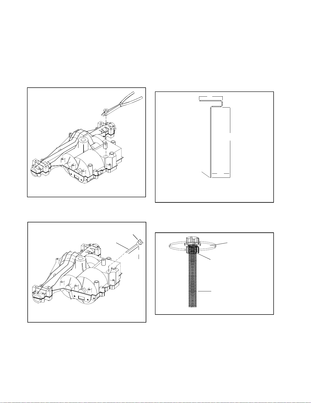
CHECKING OIL LEVEL
Main Menu
Main Menu
PROCEDURE:
1. Locate tractor on a level surface.
2. Depress clutch/brake pedal, engage parking brake
and place deck in lowest cutting position.
3. Locate the rubber fill plug next to the shift rod as
it enters the transaxle cover.
FILL PLUG
ILLUSTRATION 1
4. With a needle nose pliers or needle nose vise grip,
work under the lip of the plug, rocking from side
to side until plug is removed (Illustration 1).
DIPSTICK
NO. 35942
1/2" CONTACT IS FULL
o
45
6. If oil is needed, we recommend using a goose
neck 16 ounce mechanics oil can. (These are
readily available at any hardware store.) Fill the
unit with all 16 ounces of the 90 wt. gear oil to
level indicated.
7. Reinstall the plug by lubricating it with WD40 oil
or spray lubricant. An installation tool can be made
by using one of the following procedures.
6"
20"
ROUNDED END
3"
FILL PLUG PUSHER TOOL
3/16 ROD
ILLUSTRATION 3
A. When the plug is accessible from the battery
box area, make an installation tool from 3/
16 cold rolled steel rod as shown (Illustration
3).
LARGE FENDER
WASHER
STD. NO. 10 NUT
5. Insert dipstick Part Number 35942. Insert the gauge
62
ILLUSTRATION 2
at a 45° angle. Check for approximately 1/2 inch
of oil when inserted. This is 16 ounces of EP90
gear oil (Illustration 2).
NO. 10 SCREW
2" LONG
ILLUSTRATION 4
B. If working from the bottom or side, use a No.
10 screw approximately 2 inches long with
full threads. Then find a large fender washer
and nut for the screw. The washer will give
your fingers a large surface area to push down
on for re-installation of the plug (Illustration
4).
Page 65

SECTION 11. VST TROUBLESHOOTING
Main Menu
Main Menu
The information on the following pages has been provided to help understand the internal operation of the VST.
Do not use this information to attempt any internal repairs. Tecumseh's current policy on hydrostatic transaxles
that have internal failures is to replace the complete unit. This has not changed. However, Tecumseh would
like to provide a failure checklist to assist in making an accurate evaluation of the complete tractor to eliminate
any unnecessary replacements. Here is a list of items to check and corrective actions to take.
To properly test the unit for power loss.
1. Allow the unit to cool before trying the following steps.
2. Put the shift lever in a position that is 1/2 of the travel distance from neutral to forward.
3. Place the tractor on a 17 degree grade.
4. Drive the tractor up the grade (without the mower deck engaged). The loss of power experienced
should be approximately 20%. This is considered normal. If the loss of power is approximately 50%,
this would be considered excessive.
5. Bring the unit to neutral, shift into forward and note the response. Care should be taken to move the
lever slowly to avoid an abrupt wheel lift.
To determine if the problem is with the hydro unit, all external problem possibilities must be eliminated. Here
are some potential problem areas.
1. Overheating: Heat can cause a breakdown in the viscosity of the oil which reduces the pressure used
to move the motor. Remove any grass, debris, or dirt buildup on the transaxle cover and / or between
the cooling fins and fan. Buildup of material will reduce the cooling efficiency.
2. Belt slippage: A belt that is worn, stretched, or the wrong belt (too large or wide) can cause belt
slippage. This condition may have the same loss of power symptom as overheating. Typically, the unit
which has a slipping belt will exhibit a pulsating type motion of the mower. This can be verified visually
by watching the belt and pulley relationship. If the belt is slipping, the belt will chatter or jump on the
pulley. If the belt is good, a smooth rotation will be seen. Replace the belt and inspect the pulley for
damage.
63
Page 66
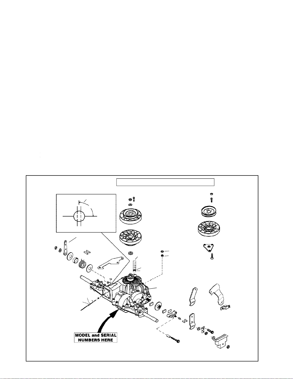
3. Leakage: The VST and 1800 Series have two oil reservoirs which can be checked for diagnostic
Main Menu
Main Menu
purposes. The first is the pump and motor expansion bellows, With a small diameter blunt or round
nose probe, check the bellows depth through the center vent hole. Proper depth from the edge of that
hole is 3-1/4 - 3-1/2 inches (8.25 - 8.9 cm).
The second chamber is for the output gears including the differential. FIRST make sure the tractor is
level, then remove the drain/fill plug. NOTE: Some units that do not have differential disconnect will
have two plugs. We recommend using only the primary plug. With a small pocket rule insert until you
touch bottom of case. You can then remove it and check for 1/4 - 3/8 inches (6.5 - 9.5 mm) contact this
is full at its 8 oz. capacity.
4. Low ground speed: If the linkage is not synchronized to absolute neutral, or the shift lever is not
properly fastened to the tapered control shaft, full forward travel may not be achieved. This may cause
a false reading and be misdiagnosed as a low power condition. This also could be caused by the brake
not releasing.
To determine absolute neutral, the hole in the tapered control shaft must face straight up and down, at
this point make sure the OEM linkage is in neutral. To properly fasten the control lever to the shaft,
torque the nut to 25-35 ft. lbs. (34 - 48.3 NM) of torque with the shaft and the lever in neutral.
When attaching the shifter arm to the shaft you must prevent any rotation during torquing. This can be
done by placing a long 5/16 bolt in the hole as shown in Illustration. Hold the bolt until the tapers are
locked and the nut torque is correct.
To make sure that the brake is not binding, drive the unit up a slight grade. Position the speed control
lever into neutral. The unit should coast backwards. If the unit does not coast back slowly, the brake
is not released from the brake disk. Adjust the brake linkage to release the brake completely when the
foot pedal is released.
5. Hard to shift: Typically hard to shift symptoms are not caused by the hydrostatic unit. The shift arm
should move with relative ease. Approximately 40-50 inch lbs. (4.48 - 5.6 NM) at the transaxle for foot
pedal units or 150-200 inch lbs. (16.8 - 22.4 NM) for hand operated units. This varies depending on the
type of linkage. Binding may occur in the linkage connections due to rust or moisture. Lubricating
these connections and checking for bent or damaged parts should resolve hard shifting.
90o from case/cover
parting line is
neutral
90
DIRECTION CONTROL SHAFT
DIRECTION CONTROL LEVER
8.2
3¼"
3½"
EXPANSION BELLOW'S
CHECK COLD FOR CORRECT DEPTH
o
Parting
Line
PRODUCT CONTAINS PATENTED FEATURES
POCKET RULE
FOR OIL CHECK
3/8
1/4
PUSH NUT
SQUARE CUT "O" RING
DIFFERENTIAL
DISCONNECT HOOKUP
64
NOTE: The above illustration is of a foot control unit with differential disconnect. Consult your parts list by model
and specification number to get correct parts for your unit. ALL PARTS SHOWN MAY NOT BE ON YOUR UNIT.
Page 67
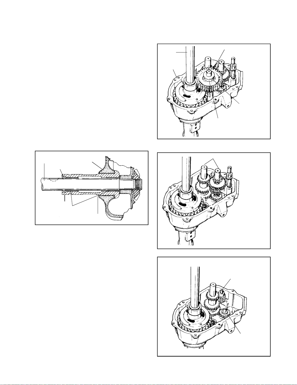
CHAPTER 4. THREE-SPEED TRANSAXLES
Main Menu
Main Menu
SECTION 1. 1200
CAUTION
TO AVOID PREMATURE TRANSAXLE FAILURE,
DECLUTCHING IS REQUIRED WHEN SHIFTING
FROM NEUTRAL TO FIRST OR REVERSE, FROM
ANY FORWARD TO REVERSE GEAR, FROM
REVERSE TO ANY FORWARD GEAR OR WHEN
OPERATING EQUIPMENT ON A HILL OR UNDER
HEAVY LOAD.
A. GENERAL
1. The 1200 series transaxles has three forward
speeds and one reverse.
2. This series is not intended for use with ground
engaging equipment. That is, it should not be
used to pull plows or similar equipment which
are pulled through the soil to over turn it. Also,
judicious use is expected in any situation where
a severe strain will be placed on the axles.
AXLE
AXLE SUPPORT
TO CASE/COVER
SEAL
AXLE
CASE
OUTPUT GEAR
THRUST
WASHER
SPACER
5. Lift the cover off from the case. Discard gasket.
Remove output gear and shaft.
SHIFTING ASSEMBLY
HOUSING
BUSHINGS
PRESS FIT
1200 Housing, Bushing and Seal Assy.
On the 1200 series, replace the seals after
complete reassembly.
B. DISASSEMBLY
1. Position the shifter forks in neutral.
2. When disassembling the unit, it should be held
so that:
a. It lies on the case, properly blocked so
that no weight rests on the input shaft or
differential, yet the case is rigid.
b. It can be worked on without the chance of
falling, or causing injury.
3. Oil seals have a double lip so seal sleeves do
not offer much protection during removal. Upon
reassembly new seals should be used.
4. Tap dowel pins into the case and remove socket
head cap screws.
6. Remove the shifting assembly as one unit.
REVERSE IDLER
GEAR SHAFT AND
SPACER
INPUT SHAFT
AND GEAR
7. Remove the reverse idler shaft, spacer and
gear.
65
Page 68
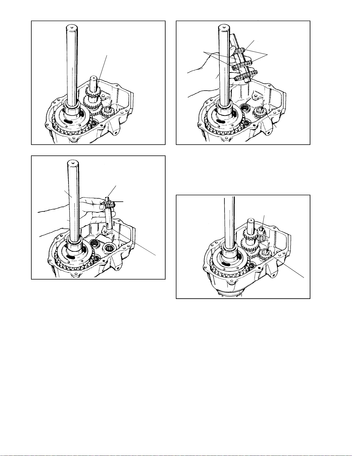
GEAR CLUSTER
Main Menu
Main Menu
ASSEMBLY
SPACER
BEVEL EDGE
DOWN
BEVEL EDGE OF
TOOTH TOWARD
LARGE GEAR
INPUT SHAFT
AND GEAR
8. Lift out the three gear cluster.
INPUT SHAFT
DIFFERENTIAL
CHAMFER
TOWARD
BEARING
OUTSIDE END
OF INPUT
SHAFT
9. Remove the input shaft.
10. Remove the differential.
NOTE: Notice what the relationship of the bolt
heads are to the removal of the assembly.
3. Install the three gear cluster, with the smallest
gear up.
NOTE: Bevels of small and middle gears go
down toward large gear. Large gear bevel is
up. The short spacer goes between the large
and middle gears.
REVERSE IDLER
GEAR SHAFT AND
SPACER
INPUT SHAFT
AND GEAR
4. Position the reverse idler shaft in the unit, then
install gear and spacer.
C. INSPECTION AND REPAIR
D. ASSEMBLY
66
Inspection of the case and cover on the 1200 series
may indicate the need for replacement of the axle
housings. Use an arbor press to drive out the
housing, and a protective piece of bar stock between
the housing and press when replacing the housing.
Press the housing in squarely until the flange seats
against the case and cover.
1. Install input shaft in case. Use a soft mallet to
seat shaft and gear completely. Binding can
occur if the shaft is driven in only part way.
2. Install the differential assembly. The four cap
screw heads should go away from output gear
or downward.
Page 69
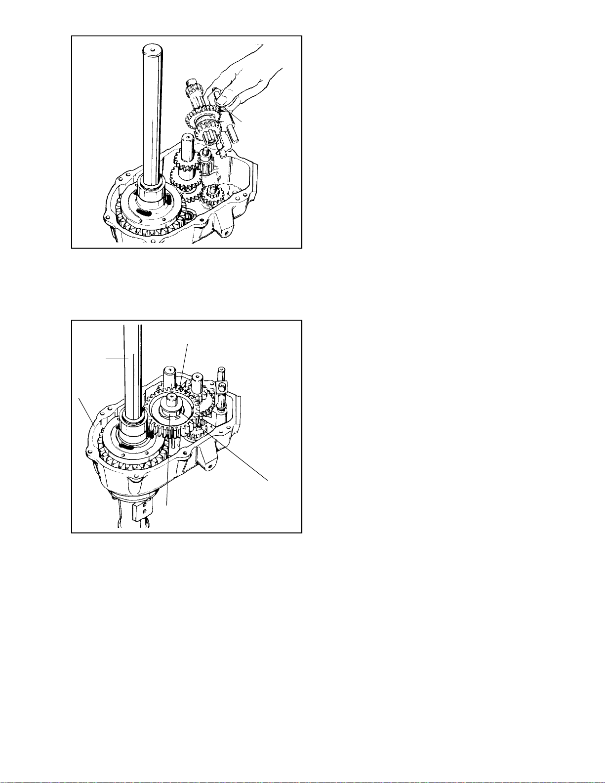
SQUEEZE TOP
Main Menu
Main Menu
OF SHIFT
RODS
5. Install the shifter assembly as a unit into the
case. When installed correctly, the neutral
square formed by the shifting forks should
appear through the case opening for attaching
the shift housing. Both shift gears should be
out of mesh.
E. LUBRICATION
Use S.A.E. 90 E.P. oil in the transaxle.
Fill units 1203, 1204, 1204-A, and 1205 thru 1208
with 3 pints oil. All other units, fill with 2 pints oil.
OUTPUT GEAR
AXLE
CASE
THRUST WASHER
SPACER
6. Install the output shaft, gear, spacer and thrust
washer.
7. Position a new gasket on the cover mounting
surface, then install cover.
8. Align cover with the dowel pin and secure with
the socket head cap screw. Torque to 10 ft.
lbs.
9. Install axle seals using sleeve and driver.
10. Install axle supports. Be sure that the mounting
pad position is correct before tightening down
cap screws to 13 ft. lbs.
11. Install a new gasket and shift lever housing.
Torque screws to 10 ft. lbs. Be sure the shift
lever is in the proper position to allow shifting.
67
Page 70
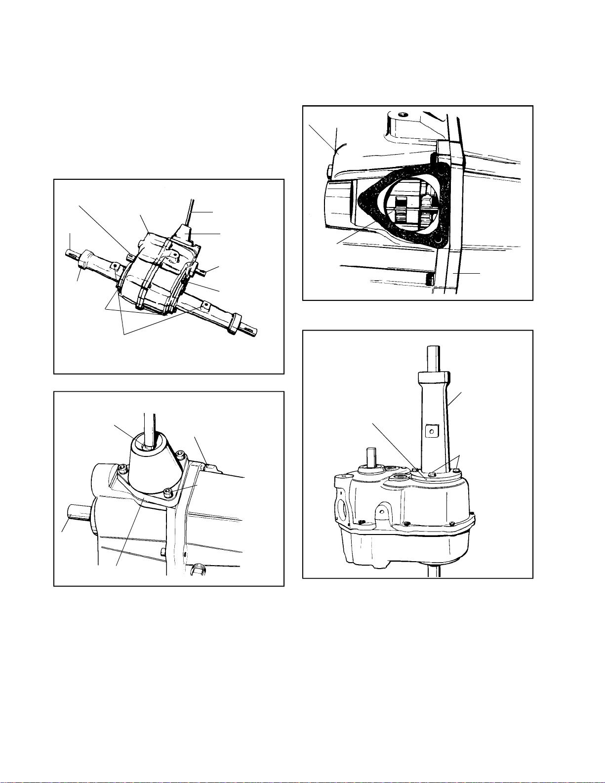
CHAPTER 5. FOUR-SPEED TRANSAXLES
Main Menu
Main Menu
SECTION 1. 2300 SERIES
CAUTION
DECLUTCHING IS REQUIRED WHEN SHIFTING TO
AVOID GEAR CLASHING AND DAMAGE.
A. GENERAL
The 2300 series transaxles have a four speed
forward and one reverse transmission.
BRAKE SHAFT
AXLE
AXLE
HOUSING
I.D. TAG
COVER
MOUNTING PADS
SHIFT LEVER
SHIFT LEVER
HOUSING
INPUT SHAFT
CASE
B. DISASSEMBLY
CASE
SHIFTING
FORKS IN
NEUTRAL
COVER
1. Position the shifter forks in neutral before
disassembly.
INTERNAL QUAD
RING SEAL USED
AT THIS POINT
INPUT
SHAFT
GASKET
ROLL OR
DOWL PIN
3 SOCKET HEAD
CAPSCREWS (TORQUE
TO 10 FT. LBS.)
AXLE HOUSING
SCRIBE MARK
(IF NECESSARY)
MOUNTING BOLTS
2. Remove both axle housings, and use the
exposed axle as a ram to separate the seal
retainers from the case and cover.
3. When disassembling the rest of the unit, it should
be held so that;
a. It lies on the cover, properly blocked up,
so that no weight rests on the brake shaft.
68
b. The cover should sit rigidly so that the
removal of parts can be done in a
systematic step by step procedure.
c. It will not fall causing an accident or injury.
Page 71
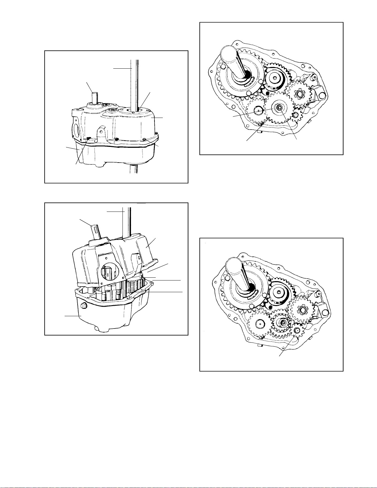
4. Oil seals are of the double lip type so sleeve
Main Menu
Main Menu
protectors do not offer much protection when
removing them. Upon replacement, new seals
should be used.
AXLE
INPUT SHAFT
COVER
DOWEL PIN
BE SURE SEAL
IS REMOVED
CASE
(8)
SOCKET
HEAD
CAPSCREWS
5. Tap dowel pins into the cover and remove the
socket head capscrews.
AXLE
INPUT SHAFT
CASE
1/32" THRUST
WASHER
3-GEAR CLUSTER
BRAKE SHAFT
7. Remove thrust washer and three gear cluster
from brake shaft, noting whether the cluster
has a sloppy fit.
a. To service the cluster bushings, refer to
the Chapter on bearing and bushing service.
b. Inspect gear teeth for wearing, chipping or
breaks. Wear or chipping on the bevel area
only, indicates shifting while the equipment
is in motion.
TURN CW
COVER
6. To separate the case from the cover:
a. Lift the case 1-1/2 to 2'’ above the cover.
b. Tilt the case so that the shift rods will clear
edge.
c. Rotate the case so that boss hidden inside
will clear gears, then lift free of the differential.
(B)
0
45
1-1/2" TO 2"
REVERSE IDLER GEAR AND SHAFT
8. Remove the reverse idler gear, spacer and shaft
from boss in cover. Note that the spacer goes
between the gear and the cover, and that the
gear bevels go down. Excessive wear on teeth
bevels indicates improper shifting technique.
69
Page 72
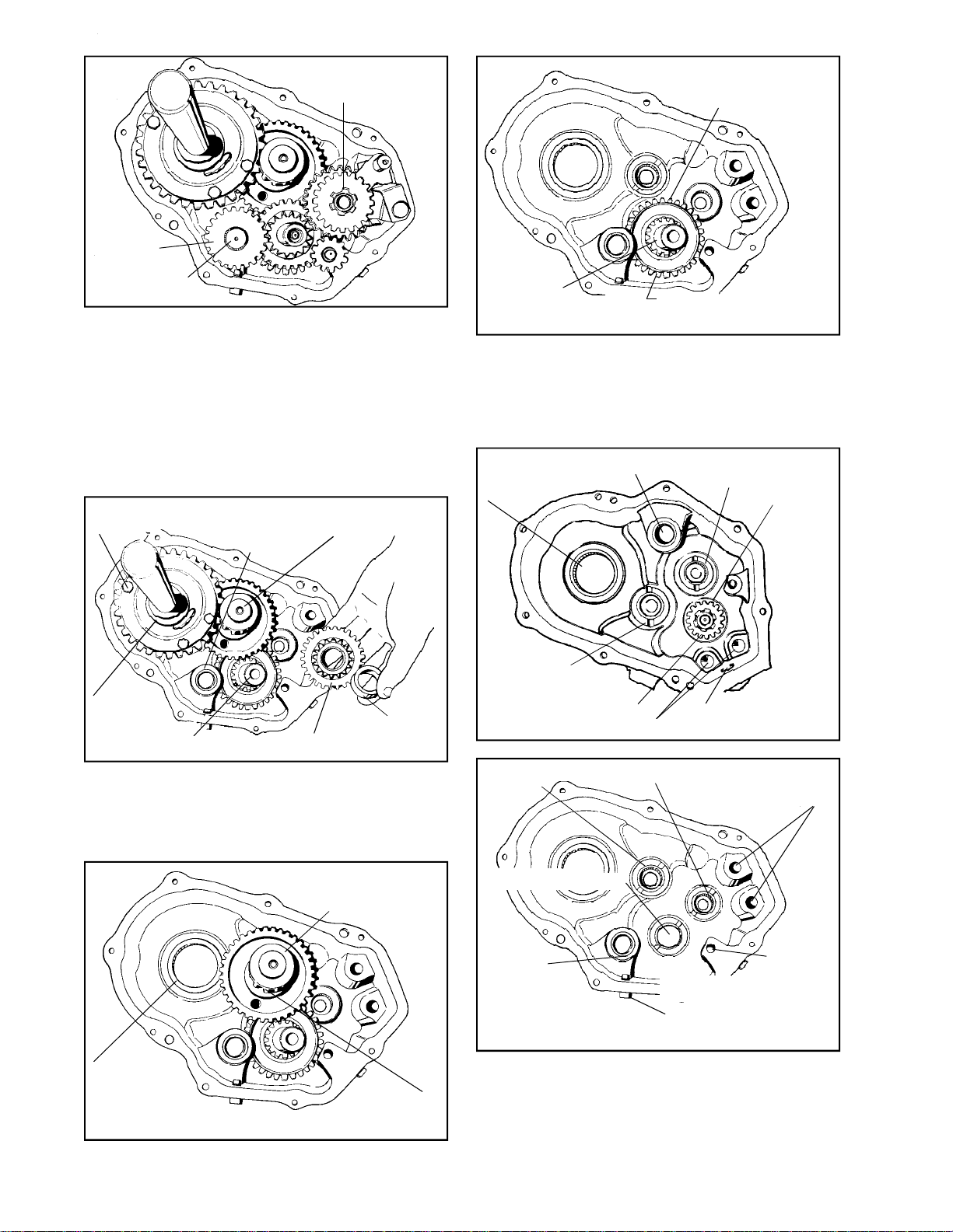
SPUR GEAR
Main Menu
Main Menu
SHIFTING
ASSEMBLY
1/32" THICK 1" I.D.
THRUST WASHER
IDLER GEAR
LOW GEAR SPUR
9. Lift out the shifter assembly. Service of this
unit is described in the Chapter on shifting
assemblies. If it is evident that the shifter
assembly needs no further teardown, place it
aside in a clean place, intact, for easy
reassembly.
10. Remove the low gear and shaft, and splined
spur gear. Separate gear and shaft. Note that
NO thrust washer is between the gear and case.
FOUR HEX BOLTS
HEADS UP
AXLE AND
DIFFERENTIAL
ASSEMBLY
BRAKE SHAFT
LOW GEAR
SHAFT
BEARING
OUTPUT GEAR
AND SHAFT
SPACER
2-GEAR CLUSTER
11. Remove the two gear cluster and spacer from
the brake shaft.
12. Lift the differential unit out of the cover. Service
information appears in the Chapter on
differentials.
1/16" THICK
15/16" I.D.
THRUST WASHER
BRAKE SHAFT
IDLER GEAR CHAMFERED SIDE
UP, AWAY FROM BEARING
14. Remove the brake shaft.
Note that the brake shaft idler separates from
the shaft. If separated, be sure that when
reassembled, the idler gear chamfers are away
from the cover.
DIFFERENTIAL
CARRIER
BEARING
OUTPUT SHAFT
BEARING
INPUT SHAFT AND GEAR
(FLAT SIDE OF GEAR UP)
*OUTPUT SHAFT
BEARING
*BRAKE SHAFT BEARING
LOW GEAR SHAFT
BEARING
SHIFTER ROD SOCKETS
*SHIFTER SHAFT BEARING
BRAKE SHAFT
BEARING
SHIFT LEVER OPENING
SHIFTER ROD SOCKETS
1/32" THICK
3/4" I.D.
THRUST
WASHER
BETWEEN
GEAR AND
BEARING
DIFFERENTIAL
AND AXLE
ASSEMBLY
REMOVED
70
OUTPUT GEAR
AND SHAFT
13. Remove the output shaft and gear and thrust
washer from each end of the shaft.
LOW GEAR
SHAFT
BEARING
*BEARING TO BE .015" - .020" BELOW THRUST SURFACE
MAGNETIC
DRAIN
PLUG
REVERSE
IDLER
SHAFT
BOSS
15. Remove input shaft from case by tapping with
a non-metallic hammer.
Page 73
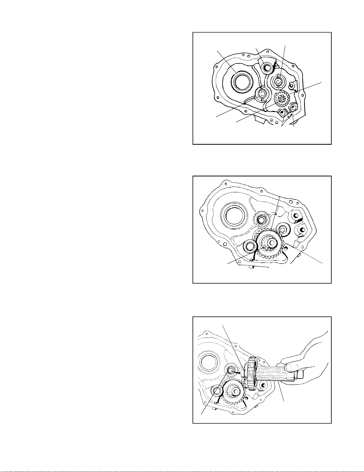
C. INSPECTION AND REPAIR
Main Menu
Main Menu
D. ASSEMBLY
1. Gears.
a. Check bevels for evidence of galling due
to improper shifting.
NOTE: Peerless Transaxles must be
stopped for shifting.
b. Check face of teeth for wear. Large shiny
areas indicate too much tooth contact and
possible excessive wear. Replace gears
indicating damage or excessive wear.
2. Shafts and Axles.
a. Check surface for rust, pitting, scratches
or wear.
b. Check keyways, splines, threads, and
grooves for wear. Replace parts if worn or
damaged beyond a refinishable state.
3. Case and Cover.
Check for cracks, stripped threads, metal chips,
flat sealing surfaces and rust. Clean out any
rust. Replace parts if any damage is found that
cannot be repaired.
4. Thrust Washers and Spacers.
DIFFERENTIAL
CARRIER
BEARING
LOW GEAR
SHAFT
BEARING
INPUT SHAFT AND
GEAR (FLAT SIDE
OF GEAR UP)
LOW GEAR
SHAFT
BEARING
BRAKE SHAFT
BEARING
SHIFTER ROD
SOCKETS
1/32" THICK
3/4" I.D.
THRUST
WASHER
BETWEEN
GEAR AND
BEARING
SHIFT LEVER
OPENING
1. Install input shaft in case. Use a soft mallet to
seat shaft and gear completely. Often, binding
in the assembled unit can be traced to a partially
installed input shaft.
1/32" THICK, 1" I.D.
THRUST WASHER
UNDER IDLER GEAR
Check for shininess indicating wear. Replace
if wear is evident. Try to determine cause of
thrust washer wear such as: lack of end play
due to reuse of gasket, or use of wrong thrust
washer.
5. Shifting Assembly.
Refer to the Chapter on shifting assemblies.
6. Gaskets.
Replace all gaskets.
7. Oil Seals.
It is a good habit to replace all seals. It is
necessary to replace all double lip seals. See
Chapter 1, paragraph F, “OIL LEAKS, SEAL
AND GASKET SERVICE”.
8. Bearings and Bushings.
Refer to the Chapter on bearings and bushings.
BRAKE SHAFT
IDLER GEAR CHAMFERED
SIDE UP, AWAY FROM
BEARING
2. Center one 1/32'’ thick by 1'’ I.D. thrust washer
on the cover brake shaft needle bearing, then
in stall the brake shaft and gear, (chamfer side
away from cover).
1/16" THICK, 15/16" I.D. THRUST WASHER
OUTPUT SHAFT
AND GEAR
OUTPUT SHAFT BEARING
3. Install the output shaft and gear after centering
a 1/16'’ thick by 15/16'’ I.D. thrust washer on
each end of the shaft.
71
Page 74
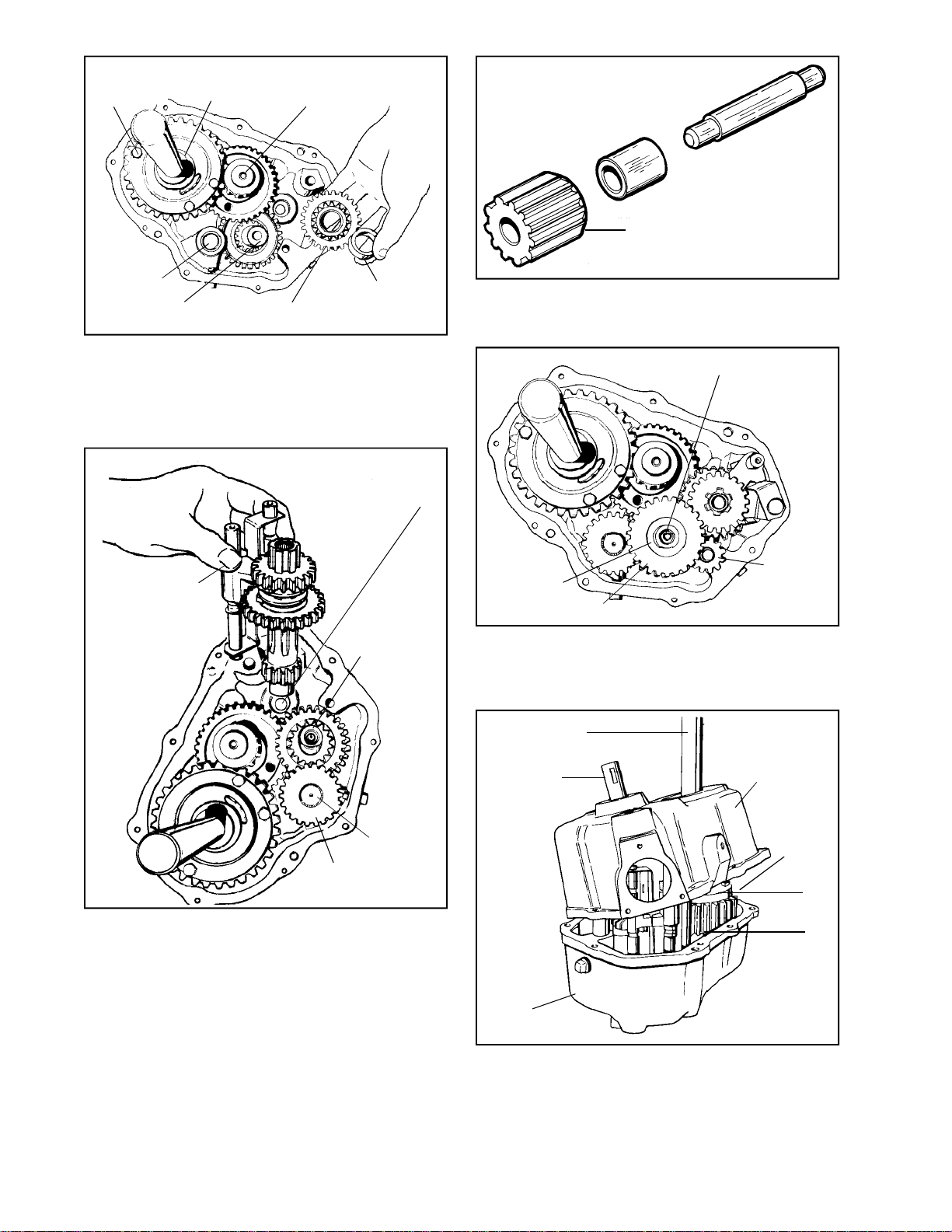
FOUR HEX
Main Menu
Main Menu
BOLTS HEADS
UP
AXLE AND
DIFFERENTIAL
ASSEMBLY
OUTPUT GEAR
AND SHAFT
BEVELED EDGE
LOW GEAR
SHAFT
BEARING
BRAKE SHAFT
2-GEAR CLUSTER
SPACER
4. Insert the differential assembly into the cover.
Note that the four bolt heads should be out
away from the output gear.
5. Install the two gear cluster and spacer on the
brake shaft.
1/32" THICK, 7/8" I.D.
THRUST WASHER IN
PLACE ON BEARING
SQUEEZE SHIFTER
RODS TO HOLD
SHIFTER ASSEMBLY
TOGETHER
TWO GEAR
CLUSTER
AND SPACER
9. Install the reverse idler shaft, spacer and gear
in to the cover. The beveled side of the idler
gear should be down into the cover.
BRAKE SHAFT
REVERSE
1/32" THRUST
WASHER
3-GEAR CLUSTER
IDLER
SHAFT
10. With the small gear of the three gear cluster
toward the spacer, install the three gear cluster
and other 1/32'’ thick by 7/8'’ I.D. thrust washer
on the brake shaft.
LOW GEAR
SHAFT
SPUR GEAR
6. Install a 1/16'’ thick by 3/4'’ I.D. thrust washer,
gear and low gear idler shaft in cover. Do not
put a thrust washer on the exposed end of this
shaft. Be sure the small gear meshes with the
larger gear of the two gear cluster.
7. Center one 1/32'’ thick by 7/8'’ I.D. thrust washer
on cover shifter shaft bearing.
8. Install shifter assembly as a unit into the cover.
AXLE
INPUT SHAFT
TURN CW
COVER
CASE
(B)
45
1-1/2" to 2"
0
11. Position the gasket on the cover sealing surface,
then install case over the differential shaft. Be
sure the boss goes under gears and that edge
of the case goes over the shaft rods in the
opposite manner from which it was removed.
72
Page 75
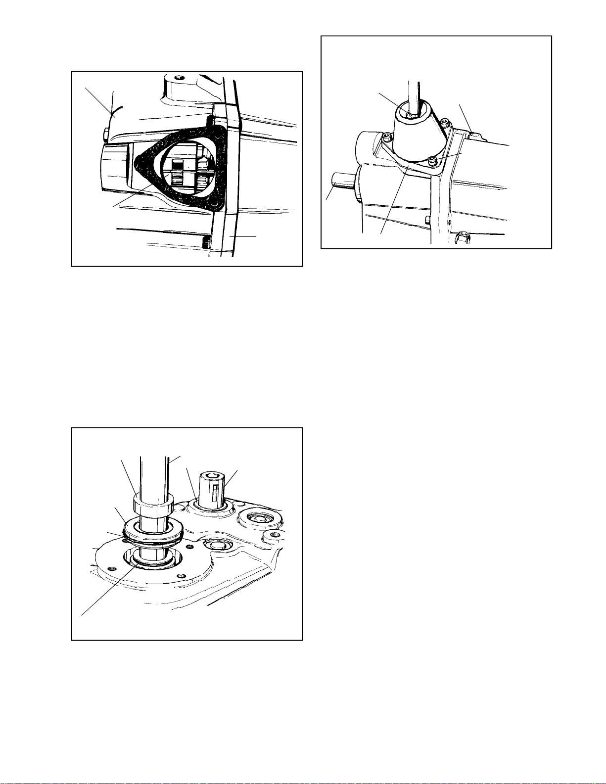
12. Once in position, if case hangs 1/2 to 1'’ high,
Main Menu
Main Menu
turn the input shaft to get gears to mesh. The
case should drop about 1/4'’ from closing.
CASE
INTERNAL QUAD
RING SEAL USED
AT THIS POINT
ROLL OR
DOWL PIN
3 SOCKET HEAD
CAPSCREWS (TORQUE
TO 10 FT. LBS.)
SHIFTING
FORKS IN
NEUTRAL
COVER
13. Use a pair of needle nose pliers on the shifter
stop on each shifter fork to agitate the shifter
rod ends into their machined recesses in the
case.
14. Align the case and cover with the two dowels,
then install and tighten the eight socket head
capscrews. Torque screws to 10 ft. lbs. Unit
can now be placed flat on the work bench.
Place seal retainers and new seals in position.
CAUTION: Sleeves must be used to protect
seals, especially axle ends or where wheels
attach.
OIL SEAL SLEEVE
(USE DURING
ASSEMBLY)
AXLE
OIL SEAL
BRAKE SHAFT
INPUT
SHAFT
GASKET
16. Install shift lever housing and new gasket.
E. TESTING AND LUBRICATION
1. For testing, refer to Chapter 1, Paragraph H.
2. For proper lubrication type and amount, refer
to Chapter 1, Section 2.
OIL SEAL
RETAINER
"O" RING
THRUST BEARING ASSEMBLY
15. Install new “O” rings on seal retainers and position
axle supports to case and cover. Be sure
mounting pads face in the same direction as
when removed. Install capscrews and torque
to 13 ft. lbs.
73
Page 76
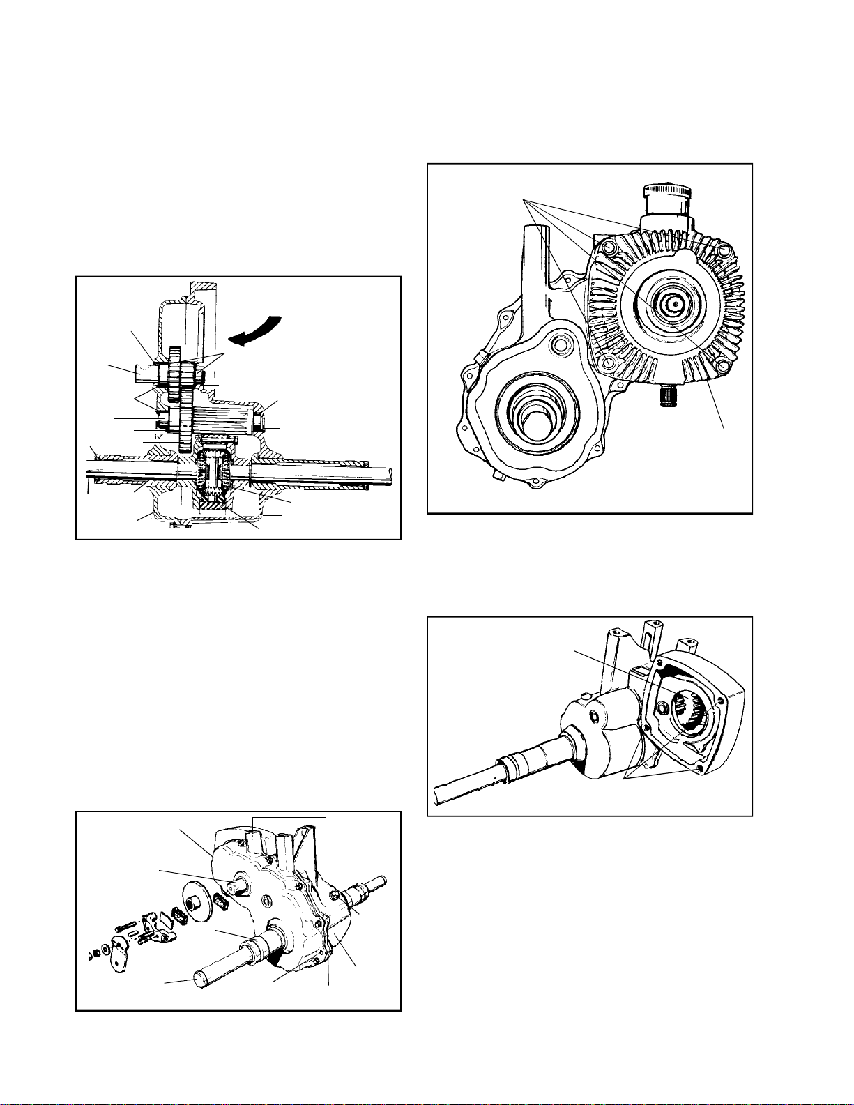
CHAPTER 6. 1300 SERIES
Main Menu
Main Menu
REDUCTION GEAR AND DIFFERENTIAL UNIT
SECTION 1. 1300 SERIES
A. GENERAL
The 1300 series unit is driven by a hydrostatic motor
connected to the unit case. The transmission function
is accomplished by the hydrostatic controls. The
Peerless unit, therefore, only reduces input shaft
speed to the differential and axle assembly.
INPUT
1
3
4
7
2
1
8
5
10
9
11
2
4
6
4
14
13
12
1. Legend for the 1300.
1 - Oil Seal 8 - Axle
2 - Thrust Washer 9 - Axle Support
3 - Brakeshaft 10 - Bushing
4 - Needle Bearing 11 - Cover
5 - Output Gear 12 - Differential Gear
6 - Output Shaft 13 - Case
7 - Spacer 14 - Thrust Washer
REMOVE MOUNTING
SCREWS (4)
HYDROSTATIC UNIT
1. To separate the hydrostatic unit from the 1300,
support both parts, then remove the four mounting
screws, and separate the parts. Drain oil from
the 1300 unit. Any hydrostatic repair must be
done through the equipment brand dealer.
INPUT GEAR (DRIVEN)
B. PRE-DISASSEMBLY
Clean the reduction unit exterior surfaces. Drain
lubricant, then separate the reduction and hydrostatic
units. Check axle shafts for cutting edges and high
spots. Due to the hardness of the shafts, a stone
may be necessary to take off metal. Check for
any evidence of oil leakage at gasket or bearing
surfaces.
COVER
BRAKE
SHAFT
AXLE
AXLE
SUPPORT
DOWEL
EQUIPMENT
MOUNTING
HOLES
OIL
LEVEL
PLUG
CASE
GASKET
Axle supports, pressed from the inside out, must be
removed with the case and cover, similar to the method
used in the 1200 series transaxle.
74
HYDROSTATIC UNIT
MOUNTING HOLES
2. After removing the hydrostatic unit, inspect the
surfaces and the gears from outside unit.
Page 77
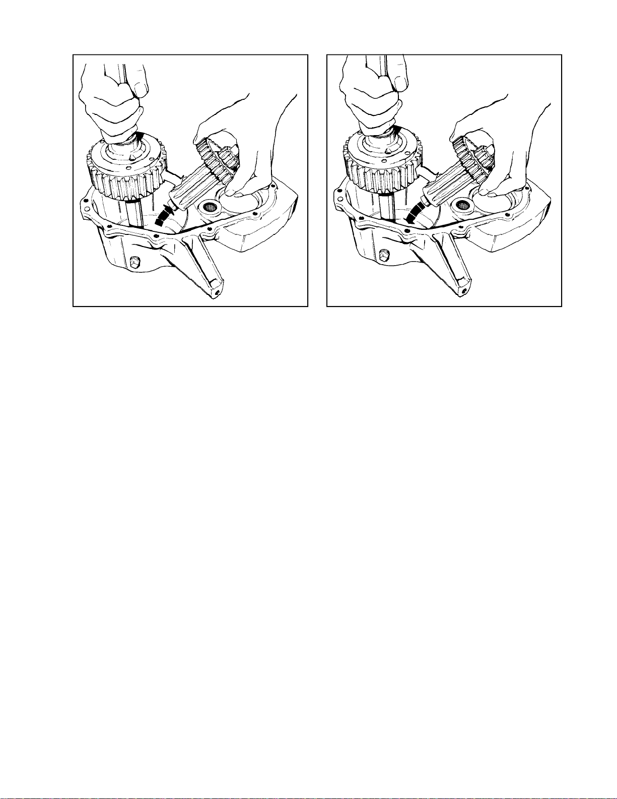
C. DISASSEMBLY E. REASSEMBLY
Main Menu
Main Menu
1. Remove the lockscrews and tap dowel pins
out of cover. Lift off cover and discard gasket.
2. Lift out brake shaft, gear, and thrust washers
on each side of gears.
3. Lift output shaft, gear, spacer, and thrust washer
from case. At the same time, lift out the
differential assembly.
NOTE: No thrust washer is located between
the output shaft and case.
4. To service differential, refer to the Chapter on
differentials.
5. To service bearings, refer to the Chapter on
bearing service.
6. To separate axle supports from the case and
cover, use an arbor or hydraulic press. A piece
of bar stock should be used to protect the support
from the press ram.
D. INSPECTION AND REPAIR
1. Inspect case and cover for cracks, stripped
threads, marred sealing surfaces, and bearing
condition. Cause of any oil leakage should be
corrected. If parts cannot be repaired, replace
them.
1. When installing axle support, be sure case and
cover alignment is true with the press. Press
sup ports in until flanged surfaces contact case
and cover.
2. Install differential and output shaft
simultaneously. Position gear 3/4'’ I.D. spacer
and thrust washer on shaft.
3. Center one 3/4'’ I.D. thrust washer over case
needle bearing then install brakeshaft gear, and
other 1-1/8'’ I.D. thrust washer.
4. Position a new gasket on the mounting surface
of the case, then install cover. Align cover and
case by tapping dowel pins into cover and secure
with lockscrews torqued to 10 ft. lbs.
5. Install new brakeshaft oil seal using sleeve
number 670179.
6. Install new axle support oil seals using sleeve
number 670179.
7. Add 2-3/4 pints (44 oz.) Oil (S.A.E. EP 90)
before securing hydrostatic drive to the 1300
series unit. Clean mounting surfaces and use
a new gasket between the units. Torque 4
mounting bolts to 90 to 100 inch pounds.
2. Check shafts and gears for worn or chipped
teeth. Check bearing surfaces for scratches
which might affect oil seal performance. Check
for wear.
3. Check needle bearing for presence, seal and
smoothness. Also, be sure bearings are not
corroded or rusty. Replace bearings of doubtful
condition.
4. Check differential for rigidity. Wobble indicates
wear. Refer to the Chapter on differentials for
service.
75
Page 78
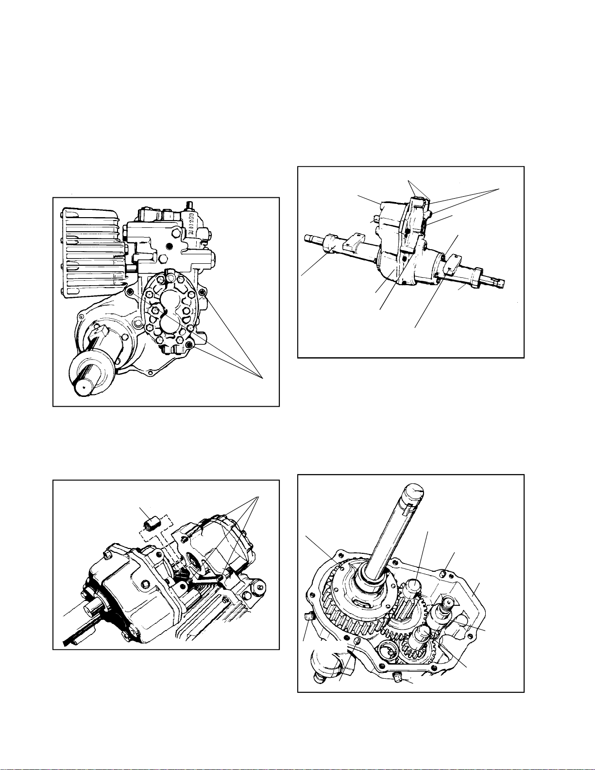
CHAPTER 7. REDUCTION GEAR AND DIFFERENTIAL
Main Menu
Main Menu
UNITS
SECTION 1. 2400 SERIES
A. 2400 SERIES
The 2400 Series transaxle is a gear reduction unit
which is powered by a hydrostatic pump.
SEPARATING AND COMBINING HYDROSTATIC UNIT
AND 2400.
d. Align the driveshaft of the hydrostatic unit to the
coupling and press the units together. Secure the
units in assembly with three socket head capscrews,
torqued to the standard for the bolt being used.
1. DISASSEMBLY
The two parts should be removed from the vehicle
together.
MOUNTING SCREWS (3)
a. To separate the units, block the assembly to prevent
falling, then remove the three hydrostatic mounting
screws. Lift either unit from the other. If any binding
occurs, remember that the drive shafts are held in
common rotation by a splined coupling and the
coupling may have a slight bind on the driveshafts.
VEHICLE MOUNTING HOLES
COVER
BRAKE SHAFT
(RIGHT SIDE HERE)
LONG AXLE SUPPORT
CASE
HYDROSTATIC UNIT
MOUNTING HOLE
PRIOR TO REMOVAL, NOTE POSITION OF MOUNTING PAD IN RELATION TO
UNIT. (ALSO NOTE SIDE TO WHICH SHORT SUPPORT AND LONG SUPPORT
ATTACH).
HYDROSTATIC UNIT
MOUNTING HOLES
INPUT SHAFT
(LEFT SIDE HERE)
AXLE SUPPORT
RETAINING BOLTS
SHORT AXLE
SUPPORT
a. Clean axles of burrs, rust and sharp edges.
b. Remove axle supports. Be sure to note in which
position and to which side they attach.
c. Drain oil from unit.
d. Remove seal retainers and “O” rings.
e. Remove eight socket head cap screws securing
case to cover. Drive dowel pins out of case
into cover, then lift case off of the cover.
COAT INSIDE OF COLLAR
WITH E.P. LITHIUM GREASE
b. Once separated, to make any further repair to the
c. To combine the hydrostatic drive and the 2400 unit,
76
MOUNTING SCREWS (3)
hydrostatic unit, it must be returned to the brand
unit dealer who sold the vehicle for his service
arrangement.
coat the splined coupling with E.P. Lithium grease,
or install it on the 2400 input driveshaft.
DIFFERENTIAL UNIT
(NOTE POSITION OF
CAPSCREW HEAD.
REASSEMBLE IN
COVER SAME WAY).
DRAIN PLUG
DOWEL PIN
DIFFERENTIAL DRIVE
PINION AND GEAR
(OUTPUT)
DOWEL PIN
COVER
INPUT
SHAFT
BRAKE SHAFT
AND GEAR
FILL LEVEL PLUG
f. Before removing differential unit, note the
position of the cap screw heads. Replace the
unit in the same way to insure that axle lengths
will be correct when installing axle supports.
Page 79
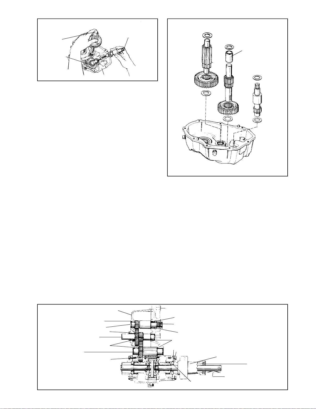
OUTPUT PINION,
Main Menu
Main Menu
GEAR AND
THRUST
WASHERS
BRAKE SHAFT
GEAR, SHAFT
AND THRUST
WASHERS
INPUT SHAFT, GEAR
AND THRUST
WASHERS
COVER
g. Remove the input shaft and gear assembly.
Note that thrust washers are on both ends of
shaft.
h. Remove output pinion and gear splined to it.
Note position of thrust washers on each end
of pinion.
i. To remove the brake shaft, the shaft must be
tapped from the gear splined to it. Use a soft
hammer. Note that both ends of the shaft have
thrust washers.
2. INSPECTION AND REPAIR
a. Clean all parts and examine for wear or damage.
b. Refer to the Chapter on differentials for service
when working on differentials. Refer to the
Chapter on bushing and bearing service to
replace any loose or worn bearings.
c. Remove and discard oil seals from input and
brake shafts. Check axle seals and replace if
any evidence of leaking exists. If protective
seal sleeves were not used when removing seals
and retainer assemblies, replace seals. Replace
seals after assembly. Use seal sleeves and
correct drivers. See Chapter 1, Paragraph F
“OIL LEAKS, SEAL AND GASKET SERVICE”
for service.
d. Clean the case and cover. Protect bearings
from dirt. Lubricate bearings to prevent rusting.
3. ASSEMBLY
a. Install thrust washer in cover for input, output
and brake shafts.
b. Install brake shaft into gear in cover.
c. Install input and output shaft (with gear) and
position spacers on brake shaft. Install thrust
washers on all shafts.
OUTPUT SHAFT
BRAKE SHAFT
SPACER
INPUT SHAFT
d. Install differential unit with cap screw, facing
down.
e. Position new gasket on slightly raised dowels
and install case. Turn down eight socket head
cap screws lightly. Tap dowel pins in and tighten
cap screws to 10 ft. lbs.
f. Use seal sleeve and install seal and retainer
assemblies. Position new “O” ring on seal
retainer. Be sure the mounting pad is in correct
position. Install each axle support and bolt down.
Torque the cap screws to 13 ft. lbs.
g. Use the proper seal sleeve and driver, replace
input and brake shaft seals.
h. Rotate shafts to check for binding or noise.
i. Add lubricant (2 pints S.A.E. EP90 oil) to level
of fill plug with unit in normal mounted position.
THRUST WASHER
INPUT
BRAKE
THRUST WASHER
OUTPUT
NOTE POSITION
OF CAPSCREW
HEADS
COVER
SEAL
CASE
THRUST WASHER
SPLINED COUPLING
SEAL
THRUST WASHER
"O" RING
SEAL RETAINER
SEAL
NOTE
POSITION
OF AXLE
SUPPORT
NOTE, EQUAL LENGTH
AXLE EXTENSION FROM
EACH SUPPORT
SEALED
BALL
BEARING
77
Page 80
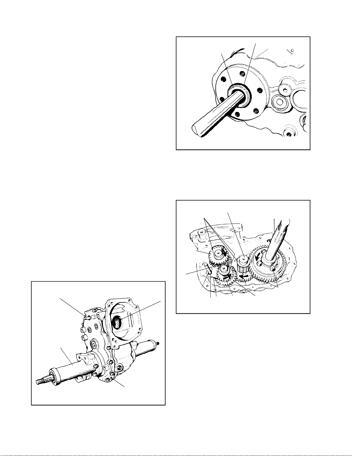
SECTION 2. 2500 SERIES
Main Menu
Main Menu
B. 2500 SERIES REDUCTION GEAR AND
DIFFERENTIAL UNIT
1. GENERAL
Most 2500 Series two speed gear boxes are run
by an Eaton Model 10 hydrostatic unit. Power for
the hydrostat is supplied by (as presently approved)
an engine up to an 18 H.P. rating. The unit has
infinite forward and reverse speeds in both a high
and low range. The 2500 series are shipped without
lubrication from Peerless. Original equipment
manufacturers fill each gear case with lubricant
when installing the 2500 in the equipment. Lubrication
for the 2500 is 7 to 8 pts. SAE Type A automatic
transmission fluid.
2. PREPARATION FOR DISASSEMBLY
a. Remove piping and hydrostatic unit as necessary
to allow repair.
b. Although the unit should have been drained of
lubrication, be aware that the axle support
removal will allow trapped oil to spill.
NOTE: An oil supply is blocked in the hydrostatic
pump when not running so upon reassembly,
hydrostatic charging is not necessary.
c. Any attempt to service the hydrostatic pump
will be done so only upon the authorization of
Eaton or the equipment manufacturer. Tecumseh
does not authorize repair or adjustment of the
unit.
TIMKEN® THRUST
ROLLER BEARING
"O" RING SEAL
b. Remove and discard square “O” ring seal.
c. If the tapered roller bearings are loose, remove
them.
d. Position the unit on the “cover up” side, then
remove the dowels and screws. Lift off the cover
and discard the gasket.
THRUST OR
TABBED
WASHERS
OUTPUT SHAFT AND
GEAR
AXLE AND
DIFFERENTIAL
ASSEMBLY
d. Clean all exterior surfaces in preparation for
disassembly.
3. DISASSEMBLY
INPUT
DRIVEN
DOWEL
AXLE
SUPPORT
BEVEL GEAR
DOWEL
a. Remove the axle supports. If supports are
different or if there is a chance for confused
reassembly, scribe alignment marks.
HIGH RANGE
DRIVEN
GEAR
LOW RANGE
DRIVEN
GEAR
SHIFT ROD
SNAP RING
FORK
HIGH RANGE
DRIVEN
GEAR
LOW RANGE
DRIVEN
GEAR
BOLT HEADS
AWAY FROM
LARGE GEAR
e. To remove the inside components, remove in
the following order:
1. Remove the differential and thrust washers.
78
Page 81
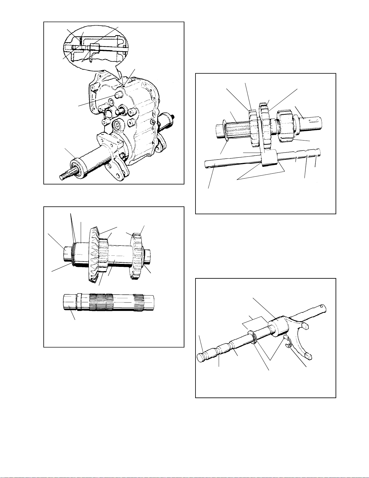
SPRING
Main Menu
Main Menu
BALL
SETSCREW
SNAP RINGS
FORK
BALL, SPRING
AND SETSCREW
b. Case and Cover
1. Check for leaks or cracks.
2. As necessary, replace needle bearings as
described in Chapter 8.
3. Do not replace brake shaft and shifter rod
seals until the unit is reassembled.
BRAKESHAFT
RETAINING
RING
2. To remove the shifter rod and fork, the set
screw, spring and ball should be removed
at the outside of the case.
INPUT
SHAFT
(Shown
Assembled)
THRUST WASHERS
SPACER
INPUT
BEVEL
GEAR
BEVELED
(ROUNDED)
SIDES
HIGH RANGE
TRANSMISSION
GEAR
BEVELED SIDE OF
GEAR TEETH
SHIFTER AND
BRAKE SHAFT
TABBED
WASHER
SHIFTER ROD
SHIFTER
FORK
HIGH RANGE
LOW RANGE
SNAP RINGS (2)
BEVELED SIDE
OF GEAR TEETH
THRUST SPACER
LOW RANGE
GROOVE
c. Shafts and Gears
1. Check teeth for wear, pitting or breakage.
2. Inspect bearing surfaces for smoothness.
3. Inspect gears and shafts for out of round.
OUPTPUT
PINIONTHRUST OR
NEUTRAL
GROOVE
HIGH RANGE
GROOVE
THRUST
BEARING
LOW RANGE TRANSMISSION GEAR
INPUT
SHAFT
SPACER
3. Remove both the input and shifter gear and
shaft assemblies, along with the shifter rod
and fork.
4. Remove the input shaft and gear assembly.
5. Remove the output shaft and gear.
4. INSPECTION AND REPAIR
a. Axle Supports
1. Check ball bearings and bearing races for
wear, rust and ease of rotation. Clean interior
of the support if necessary.
2. Replace oil seals in axle supports.
3. Check for cracks.
THRUST OR
TABBED
WASHER
4. Splines should allow a smooth fit. Rotate
meshing parts for a better fit if binding seems
excessive.
SHIFTER FORK
(PARTIALLY REMOVED)
FORK NORMAL
POSITION
HIGH RANGE
GROOVE
NEUTRAL
LOW
RANGE
GROOVE
SNAP RINGS
(SHARP SIDE OUT)
d. Shifter Mechanism
1. Check spring for tension and ball for wear.
2. Check shifter rod grooves for wear. Be sure
snap ring sharp edge goes away from shifter
fork.
3. Inspect shifter fork for straightness and
wear.
79
Page 82
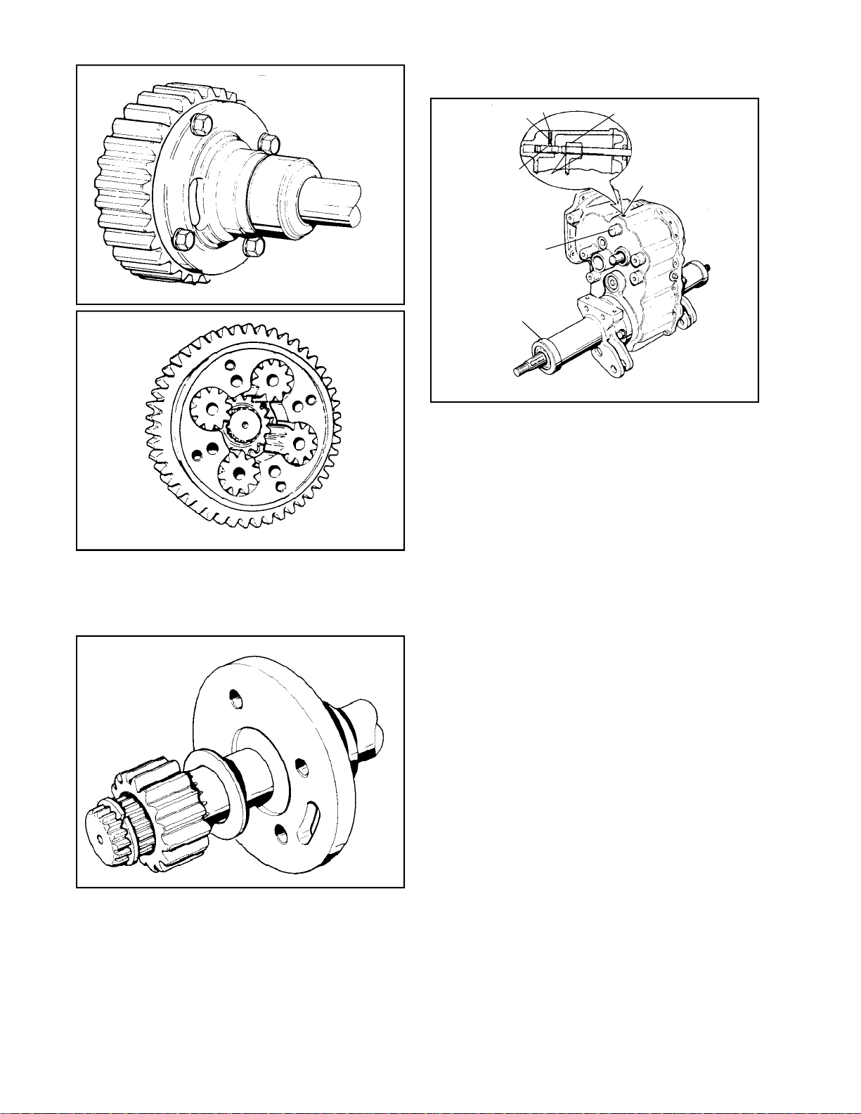
e. Differential 5. ASSEMBLY
Main Menu
Main Menu
Install parts reversing the disassembly procedure,
watching out for the following:
SPRING
SETSCREW
FORK
1. Check security of parts.
2. Check snap rings for condition and
presence.
f. Other
BALL
SNAP
RINGS
BRAKESHAFT
RETAINING RING
BALL, SPRING AND
SETSCREW
a. After shifter rod is positioned, install ball, then
spring and setscrew. Turn setscrew in slowly
while raising and lowering rod, until ball stops
rod movement.
b. Be sure that thrust washers and spacers are
between every shaft and case and cover.
c. Threads of differential bolts must be coated
with standard stud Loctite. The bolt heads on
differential are up when installed.
d. Install new gasket. It may be helpful to dampen
the gasket with oil to get it to lie flat.
e. Use seal sleeve to protect axle support oil seals
during installation
1. Check thrust washers for wear.
2. Check tapered roller bearings for wear and
ease of rotation.
3. Replace shifter rod oil seal after assembly
of all parts.
4. Check thrust bearing for wear and presence
of rollers.
g. Replace any parts necessary.
80
f. Install axle supports correctly. Do not rotate
the support to a new position when pressed
tight against the square “O” ring seal or the
seal may be cut.
6. AFTER ASSEMBLY
a. To install brake shaft oil seal, use seal sleeve
670179.
b. To install shifter rod oil seal, use seal sleeve
670206 and driver 670211.
c. Lubrication for all models is 7 to 8 pints of
S.A.E. Type A automatic transmission fluid.
When filling with fluid allow fluid to settle behind
the tapered bearings into the axle supports.
This may necessitate filling, checking and
adding. The lubrication fill and check hole is
located in the case. If the shrouding on the
vehicle does not allow access to the fill and
check hole when the 2500 is installed in the
chassis, lubrication should be filled prior to
installation on vehicle. If filling takes place before
installing the 2500 in vehicle, the unit must be
oriented, or at a 90o angle to the axles. There
should be no fluid leak.
d. Install drive assembly according to
manufacturer’s instructions.
Page 83
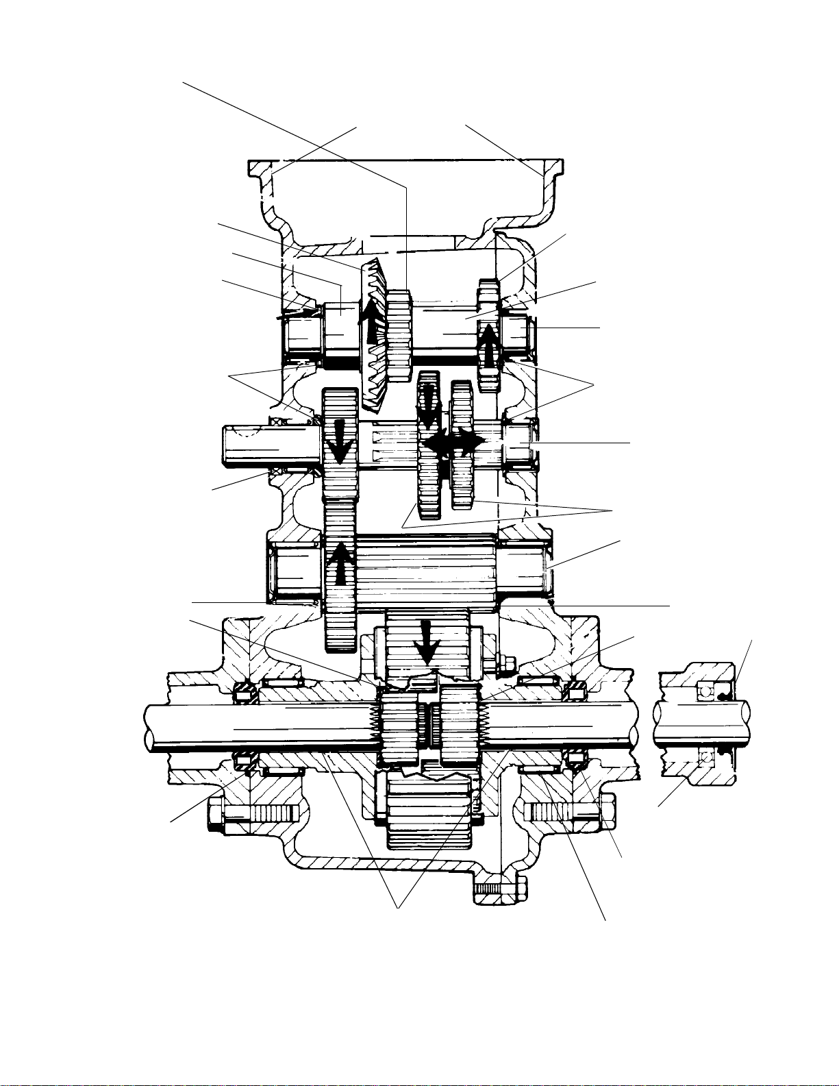
LOW RANGE TRANSMISSION
Main Menu
Main Menu
DRIVE GEAR
DRIVEN
INPUT
GEAR
SPACER
HYDROSTATIC DRIVE
MOUNTING SURFACE
HIGH RANGE TRANSMISSION
DRIVE GEAR
THRUST BEARING
THRUST WASHER
OIL SEAL
TABBED THRUST
WASHER
THRUST WASHER
SPACER OR SHOULDER
INPUT SHAFT
TABBED THRUST
WASHER
SHIFTER AND BRAKE
SHAFT
BEVELED SIDES OF GEARS
OUTPUT SHAFT
TABBED
THRUST
WASHER
THRUST
WASHER
SEAL
"O" RING SEAL
BALL BEARINGS (2)
ROLLER BEARINGS (2)
NOTE: NO BEARING AT THESE POINTS
NEEDLE BEARINGS (2)
81
Page 84
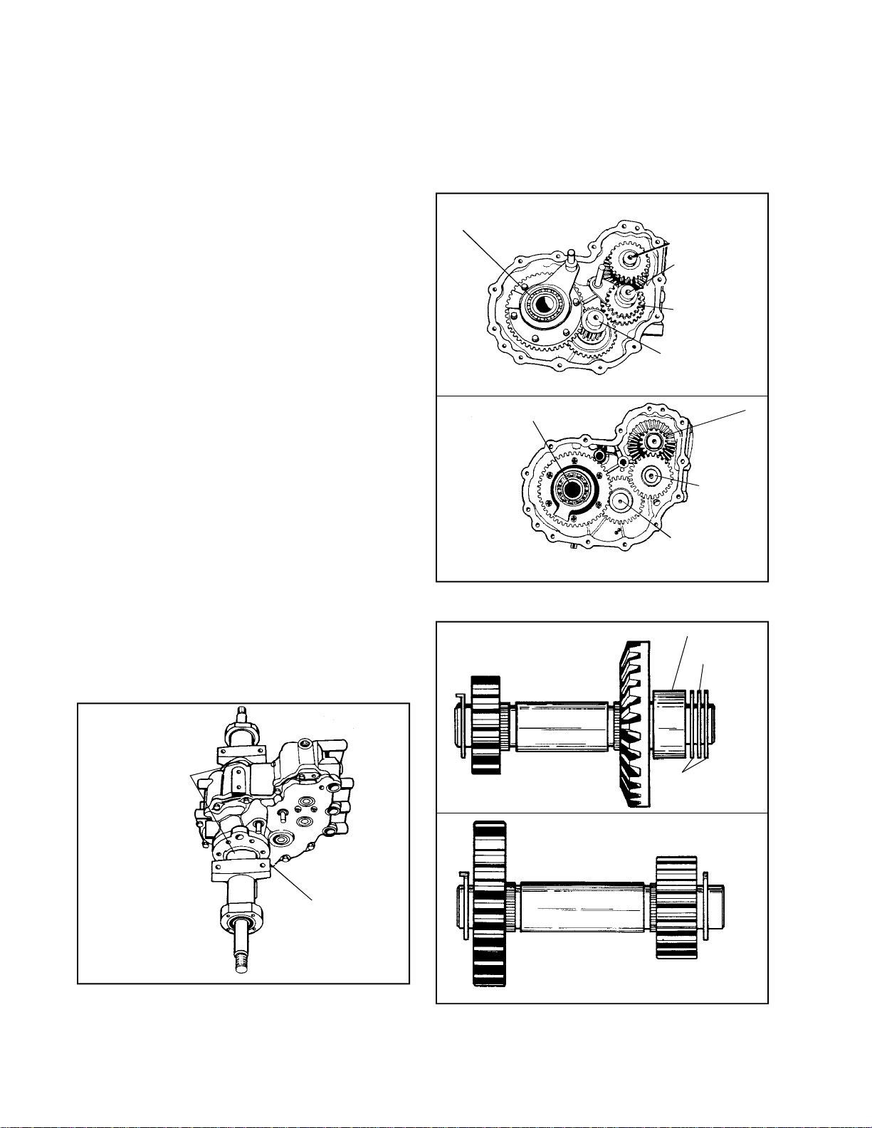
SECTION 3. 2600 SERIES REDUCTION GEAR AND DIFFERENTIAL UNIT
Main Menu
Main Menu
1. GENERAL
The 2600 series has infinite forward and reverse
speeds. It is powered by a Sundstrand unit. Power
to the hydrostat is an engine up to 20 H.P. rating.
The 2600 series are shipped without lubrication from
Peerless. Original equipment manufacturers fill each
gear case with lubricant when installing the 2600
in the equipment. Lubrication for the 2600 is 7 to 8
pts. SAE Type A automatic transmission fluid.
2. PREPARATION FOR DISASSEMBLY
a. Remove piping and hydrostatic unit as necessary
to allow repair.
NOTE: An oil supply is blocked in the hydrostatic
pump when not running so upon reassembly,
hydrostatic charging is not necessary.
b. Although the unit should have been drained of
lubrication, be aware that the support removal
will also remove the axle along with it. This
will allow trapped oil to spill.
c. Any attempt to service the hydrostatic pump
will be done only upon the authorization of
Sundstrand or the equipment manufacturer.
Tecumseh does not authorize repair or
adjustments of that unit.
d. Clean all exterior surfaces in preparation for
disassembly.
3. DISASSEMBLY
a. Remove the axle supports. If supports are
different or a chance for confused reassembly,
scribe alignment marks.
c. Position the unit with cover side up. Then remove
dowels and screws. Lift cover off, discard
gasket.
d. To remove the inside components, remove them
in the following order.
DIFFERENTIAL
INPUT SHAFT
SHIFTER SHAFT
SHIFTER GEAR
CLUSTER
OUTPUT SHAFT
Dual Range with Lock Differential
INPUT SHAFT
DIFFERENTIAL
COUNTER
SHAFT
OUTPUT SHAFT
Single Range without Lock Differential
1. There are two different 2600 models, shown
above -
SPACER
THRUST
BEARING
ALIGNMENT SLEVES
WILL BE PRESENT
BETWEEN AXLE
SUPPORT AND UNIT
82
I.D. TAG
b. To remove axle out of support, tap lightly with
a mallet from inside out. A pressed on sealed
bearing will be on the end of axle.
THRUST
INPUT SHAFT
COUNTER SHAFT
WASHERS
2. To remove components in the single speed,
first remove the differential, thrust washers,
drive gear, input shaft, countershaft, output
gear and shaft.
Page 85
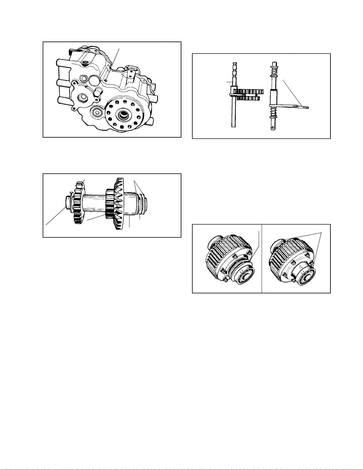
3. To remove components in the 2 speed with
Main Menu
Main Menu
locking differential, remove in following
order.
4. Splines should allow a smooth fit. Rotate
meshing parts for a better fit if binding seems
excessive.
a. To remove the shifter rod and fork,
HIGH RANGE GEAR
INPUT SHAFT
BOLT, SPRING AND BALL
remove the outside bolt, spring and ball.
Remove high range gear then shifter
gear cluster and fork assembly together.
THRUST WASHERS
LOW RANGE
GEAR
THRUST BEARING
SPACER
d. Shifter Mechanism (Dual Range).
DIFFERENTIAL LOCK
HI-LOW SHIFT
FORK AND
ROD
FORK ASSEMBLY
1. Check spring for tension and ball for wear.
2. Check shifter rod grooves for wear. Be sure
snap ring sharp edges goes away from
shifter fork, on both shifter shafts.
3. Inspect shifter fork for straightness and
wear.
e. Differential.
1. Check security of parts.
2. Check thrust washers for wear.
LOCK COLLAR AND PIN ASSY.
BALL BEARING
b. Remove input shaft assembly.
c. Remove shifter shaft, output shaft and
out put gear in this order.
d. Remove differential and lock fork
assembly together.
4. INSPECTION AND REPAIR
a. Axle Supports.
1. Check roller bearings on the axles, remove
any rust and clean.
2. Clean axle supports and inspect.
b. Case and Cover.
1. Check for leaks or cracks.
2. Replace oil seals.
3. As necessary, replace needle bearings as
described in the Chapter on bearing service.
4. Do not replace brake shaft seal, brake shaft,
shifter rod and shifter differential lock seals,
until the unit is reassembled.
c. Shafts and Gears.
1. Check teeth for wear, pitting or breakage.
2. Inspect bearing surfaces for smoothness.
3. Inspect gears and shafts for out of round.
LOCK DIFFERENTIAL
NON-LOCK DIFFERNETIAL
3. Check differential lock collar for fork slop
or pin wear.
4. Check ball bearings for ease of rotation.
f. Replace any parts if necessary.
5. ASSEMBLY
Install parts reversing the disassembly procedure,
watching out for the following:
a. After shifter rod is positioned, install ball, then
spring and setscrew. Turn set screw in. (Dual
speed) until head or screw contacts case.
b. Be sure that thrust washers and spacers are
between every shaft and case and cover.
c. Threads of differential bolts must be coated
with standard stud Loctite. The bolt heads
installed are up. Refer to the differential Chapter.
d. Install new gasket. It may be helpful to dampen
the gasket with oil to get it to lie flat.
83
Page 86

e. To place axle assemblies into case and/or cover,
Main Menu
Main Menu
grease axle spline ends heavily. Push axle
through seal, use extreme caution when axle
splines are going through seal.
6. AFTER ASSEMBLY
a. To install brake shaft oil seal, use seal sleeve
670179 and seal driver.
b. To install shifter rod oil seal, use seal sleeve
670206 and driver 670211.
c. To install locking differential shifter rod oil seal,
use seal sleeve 670206 and drive 670211.
d. Lubrication for all models is 7 to 8 pints of
SAE Type A automatic transmission fluid.
84
Page 87
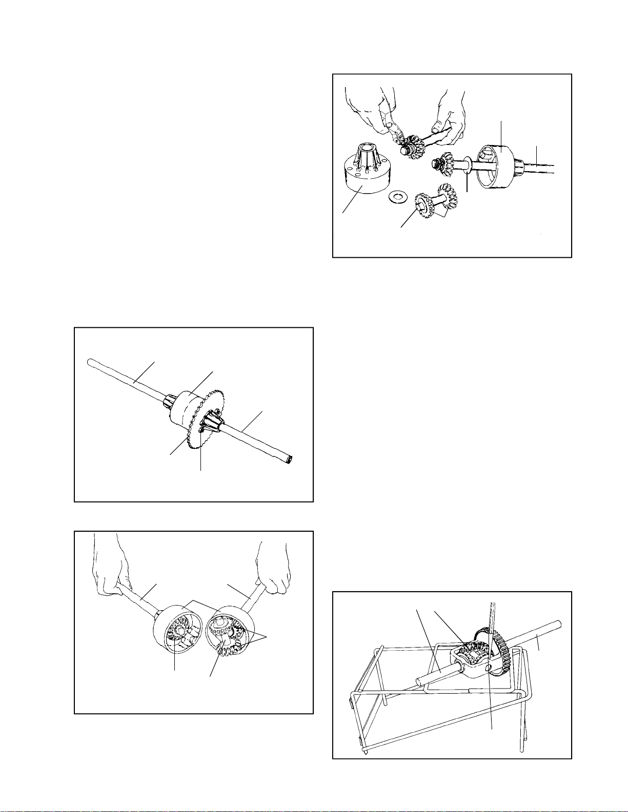
CHAPTER 8. DIFFERENTIALS
Main Menu
Main Menu
A. GENERAL
The differential assemblies, of all Peerless units
utilizing them, are grouped together in this section.
Though there is little similarity between the 100,
600, 800 and remaining series units, they are grouped
here because their function is the same.
The differential assemblies for the 820, 1200, 1300,
2300 and 2400 series Peerless units are very similar.
However, each must be assembled in its own way.
By grouping them together, you will become more
aware of differences in each unit, therefore less
apt to allow these differences to cause mistakes
in assembly.
B. MODEL 100 DIFFERENTIAL
1. DISASSEMBLY
a. Clean outside of differential. Remove all
keys, pins, etc. Remove all burrs from
keyways and holes. Use a stone on
hardened shafts.
AXLE
HOUSING
100 SERIES DIFFERENTIAL
HOUSING
HOUSING
SNAP RING
THRUST WASHER
PINION GEARS
DRIVE PIN
d. Remove snap ring, bevel gear and thrust
washer. Slide axle from differential carrier
housing.
NOTE: Bushings are replaceable in the
differential carrier housing. To replace
bushing, use bushing tool 670204.
2. ASSEMBLY
a. Slip axle in differential housing carrier. Place
thrust washer and bevel gear on axle and
secure with snap ring. Make sure flat side
of snap ring is away from gear.
AXLE
AXLE
SPROCKET
LOCK NUTS (4)
b. Remove 4 locknuts, bolts and sprocket.
Separate differential carrier housings.
AXLE
BEVEL GEAR
AXLE
HOUSING
PINION
GEARS
DRIVE PIN
b. Place pinion gears and thrust washers on
drive pin and insert assembly into either
differential housing carrier.
c. Use 3 oz. Bentonite grease as lubricant.
d. Assemble differential carrier housings and
sprocket with 4 bolts and locknuts.
NOTE: No oil seals or gaskets are required
in this unit. A few units use a gasket between
the two housings.
If no gasket is present, seal the housing
with Loctite 598 part number 788093 using
a 1/8" bead.
C. MODELS 600, 800, 900, 910, 915, 920 and 930
1. DISASSEMBLY of 600
AXLE
DRIVE PIN
AXLE
c. Remove drive pin, pinion gears and thrust
washers as a unit.
ROLL PIN
a. Drive out roll pin that secures drive pin
with suitable driver.
85
Page 88
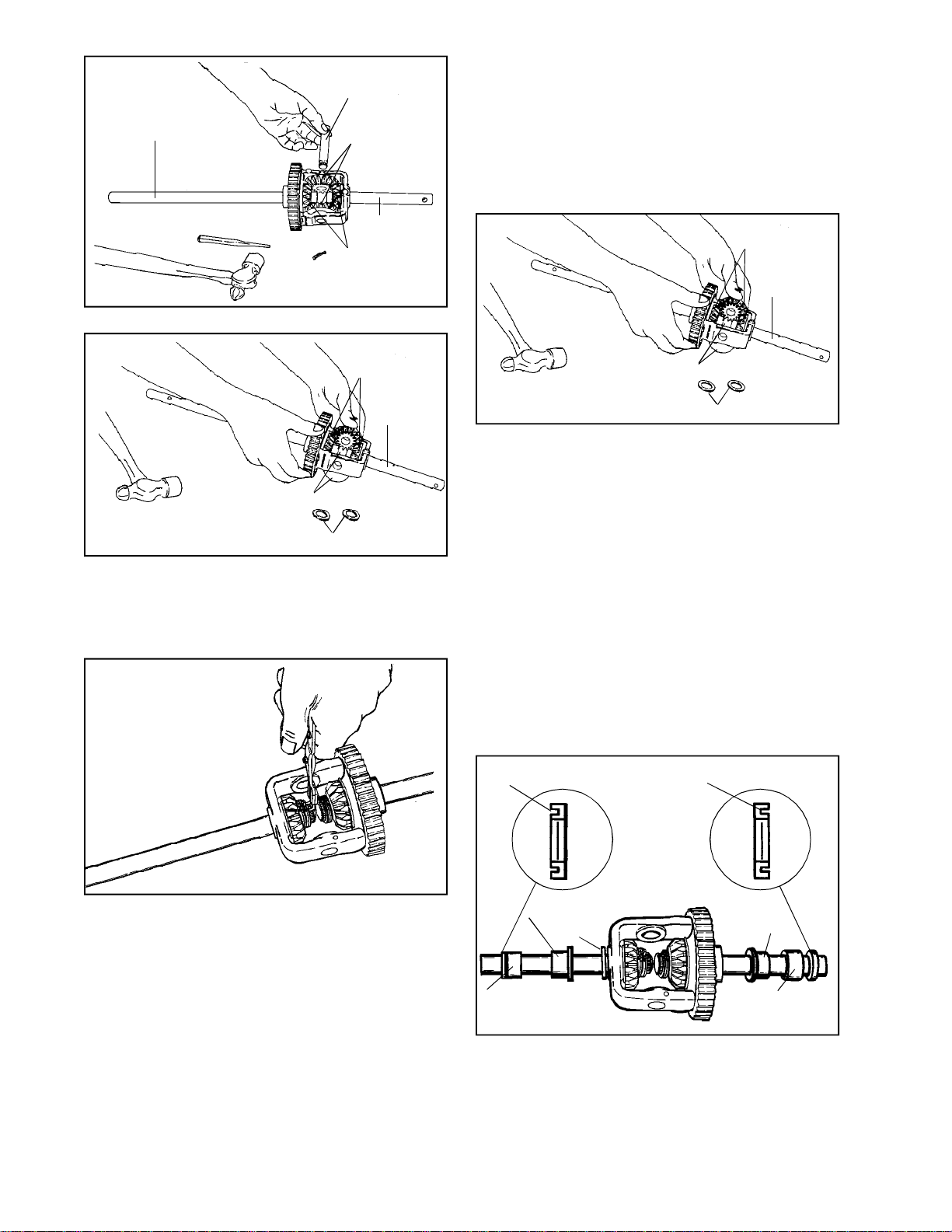
AXLE
Main Menu
Main Menu
b. Remove drive pin.
DRIVE PIN
BEVEL PINIONS
AXLE
BEVEL GEARS
c. Install bevel pinions SIMULTANEOUSLY
FROM OPPOSITE SIDES by rotating
pinions in opposite directions while sliding
into position in gear assembly. Check
alignment by inserting fingers into drive pin
holes. If not aligned, drive pin cannot be
inserted. Remove and replace bevel pinions
as only one tooth out of position will cause
misalignment.
BEVEL GEARS
AXLE
BEVEL GEARS
AXLE
BEVEL PINIONS
THRUST WASHERS
c. Thrust washers must be removed before
attempting to remove the pinions. Remove
bevel pinions simultaneously by rotating
the gears in opposite directions; gears will
move out of position.
SNAP RING
BEVEL PINIONS
THRUST WASHERS
d. After aligning, insert thrust washers behind
each pinion. Insert drive pin and secure
with roll pin.
C-1. MODEL of 800
1. DISASSEMBLY
a. Same as disassembly for model 600, except
for additional parts on the axle.
b. Remove and inspect seals, bearings and
washers for wear replace if required.
c. If differential was disassembled note positioning
of differing length axles so correct reassembly
may be performed.
2. REASSEMBLY
a. Reassemble in reverse order of disassembly.
CUP FACES
OUT
CUP FACES
OUT
2. REASSEMBLY OF DIFFERENTIAL ASSEMBLY
86
d. Remove snap ring, bevel gear and thrust
washer. Slide axle out.
e. Inspect bushings and gears for wear and
replace when necessary.
a. Place axles (left and right) into differential
gear assembly. Install thrust washers.
NOTE: The axles differ in length so select
the proper axle.
b. Place bevel gears on the shaft and install
snap ring in groove on the shaft.
SEAL
BEARING
WASHERS
BEARING
(NEEDLE TYPE)
SEAL
BEARING
BEARING
(NEEDLE TYPE)
b. Install seal cup end out from the center of
differential to prevent dirt entry.
Page 89
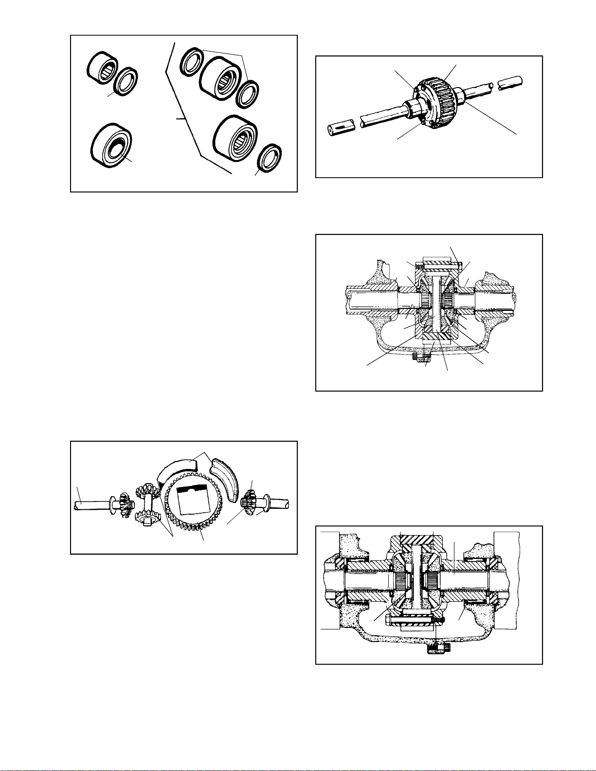
OLD STYLE
Main Menu
Main Menu
"A"
"C"
SEAL
NEW STYLE
"D"
HEAVY DUTY SEALED
BALL BEARING
SQUARE CUT
"O" RING
"B"
SEAL
The 800 Series has used 4 styles of bearings on the
axles. The earliest style “A” was a smaller loose cage
needle bearing and must have the seal to the outside
of that bearing. Style “B” must have the seal to the
out side of the bearing. When bearing style “C” is used,
a square cut “O” ring must be used on each side of
the bearing. Bearing style “D” is a sealed ball bearing
used in H.D. application. Styles “B”, “C” and “D” are
inter changeable. All needle bearings must be repacked
with grease.
D. DIFFERENTIAL USED IN PEERLESS CAST IRON
CASING UNITS
DIFFERENTIAL
HEX HEAD BOLT
RING GEAR
BEARING SURFACE
NOTE: The models covered are the 820, 1200, 1300,
1700, 2000, 2300 and 2400 series.
1. The differential construction may vary from the
illustrations but is basically similar.
FOUR RETAINING BOLTS
8
6
5
SNAP RING
RETAINER
4
C-2. MODEL of 900, 910, 915, 920 and 930
1. DIFFERENTIAL
Remove differential from case. The differential
is one of the first of its kind in that the unit
rides and is held together in the case and cover.
Also remove the flat washers off the axle ends.
Some models will have a slightly different ring
gear and use a single bearing strap in place of
bearing blocks.
2. DIFFERENTIAL ASSEMBLY
BEARING BLOCKS
BEVEL
AXLE
BEVEL PINIONS
RING GEAR
GEAR
WASHER
2 SNAP RINGS
When assembling this unit, make sure all parts
are there first, because the unit is put together
in your hands and placed in the case at the
same time.
2
3
PINION GEAR
DRIVE BLOCK
DRIVE PIN
DIFFERENTIAL
CARRIER WITH
THREADED
BOLT HOLES
1
7
DIFFERENTIAL
GEAR
2. The 1200 series differential carrier is supported
directly on the axle (1). Roller thrust bearings
(2) are used between the bevel gear (3) and
the differential carrier (4). This illustration shows
axles with snap ring (5) retainers, some earlier
production had rolled over axle ends to secure
the assembly. Thrust washers (6) are used at
the ends of the differential carriers and case/
cover thrust face. The drive pin (7) and drive
blocks (8) are similar to those used on the 1700
series. Replace the differential carrier if worn
in excess of .878 at point A.
2
POINT A
3. MST SERIES DIFFERENTIAL
This unit is similiar to the 900, accept it uses
no bearing blocks. The differential is supported
by the shoulders on the ring gear.
3
1
3. The 2000 series, three speed and the 2300
series, four speed differential. Examine the
external bearing race on the differential carriers
(1) for wear or pitting. Replace if evident. The
differential carriers in this assembly have
replaceable bushings (2). Replace if worn in
87
Page 90
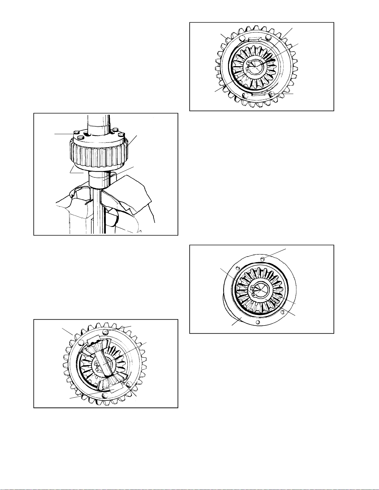
excess of .878 at point A. See the Chapter on
Main Menu
Main Menu
Bushing and Bearing Service. These differentials
have been built with rolled axle ends and also
snap rings (3), as illustrated.
1. DISASSEMBLY
a. Clean the differential assembly, then check
and note the axle lengths and their relation
to the heads of the four hex screw bolts.
RING GEAR
SNAP RING
AXLE END
b. If the unit will not turn freely, note where
the unit binds. Check and replace those
parts.
FOUR HEX
HEAD
BOLTS
BEARING RACE
DIFFERENTIAL
CARRIER
c. Place the differential in a large vise with
soft jaws (hex head bolts up). Do not clamp
the vise on the bearing race of a differential
carrier.
1. Remove the four hex head bolts and
the upper axle and differential carrier.
Remove the drive blocks, pinions, drive
pin and thrust spacer if used, by lifting
out of the ring gear. Tap the ring gear
lightly with a mallet to loosen from the
differential carrier.
RING GEAR
THRU BOLT HOLES
RING GEAR
DRIVE PIN
THRUST
WASHER
DRIVE BLOCK
SEAT
3. Remove the snap ring and the thrust
washer, if used. Separate the bevel gear
and the differential carrier from the axle.
2. INSPECTION
a. See the Chapter on Bushing and Bearing
Service.
b. Examine gears for wear, cracked or chipped
teeth. Check the internal splines of the
gears and axle if the gear is removeable.
If excess play is noted, it may be necessary
to replace the individual parts or both the
gear and axle.
c. Examine drive pinions, drive pins and drive
blocks for wear and damage. Replace
excessively worn pinion or the drive pin.
HOLES THREADED
IN ONLY ONE
SNAP RING
DIFFERENTIAL
CARRIER RING
GEAR REMOVED
DIFFERENTIAL
CARRIER
BEVEL GEAR
THRUST
WASHER
d. Examine the differential carriers. One has
threaded holes and the other has larger
holes so that the bolts will pass through.
Be sure to order the correct replacement
parts.
DRIVE BLOCK
88
e. Examine the internal bearing diameter of
the differential carriers.
TWO PINIONS
2. If a snap ring is used, the axle assembly
may be disassembled. If the axle end
has been rolled, do not attempt to break
the rolled retaining edge. The parts are
to be replaced as an assembly.
Page 91
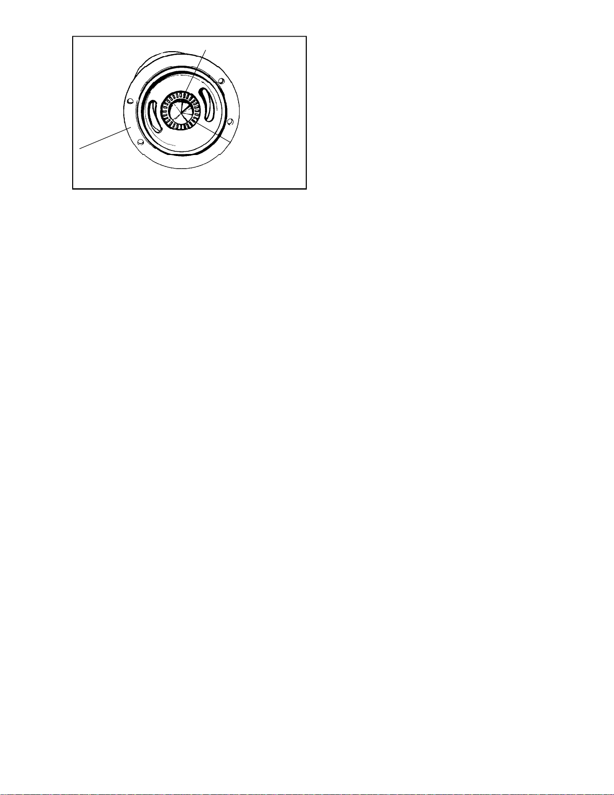
SERRATED AXLE END
Main Menu
Main Menu
ROLLER THRUST
DIFFERENTIAL
CARRIER
BEARING WITH
ONE THRUST
WASHER
f. When assembling thrust bearings, always
place a hardened thrust washer on each
side of the caged thrust rollers. Never use
the caged thrust rollers without the thrust
washers.
3. REASSEMBLY
a. Oil all parts during reassembly.
1. Select the correct axle for the side of
the differential opposite the hex head
bolts. If the wrong axle is used it will
require complete teardown of the
differential, or possibly the entire
transaxle, if the error is not detected
until later.
2. Clamp the axle, in a soft jaw vise (not
bearing or oil seal surfaces). The
differential carrier with threaded holes
is assembled to this axle.
2. DISASSEMBLY, INSPECTION AND REPAIR
Parts breakdown will be found on next page.
Remove four through-bolts. Separate axle
assemblies from body cores. To disassemble
axles, remove snap ring and retained parts.
Be sure that flanged thrust washer goes toward
hub end of axle upon reassembly. Use a pair
of large 90o tip snap ring pliers and remove the
cylindrical spring putting tension on the ten pinion
gears. Once the spring is removed, the gears
can be removed. Separate the two body cores
from the ring gear.
3. ASSEMBLY
Install body cores to ring gear so that pockets
in one core are out of alignment with pockets
in other core. Reassemble thrust washers,
bearing, carrier and side gear to axle and secure
with the snap ring. Install pinion gears on one
side, then use the differential carrier and axle
to hold them from falling out when the unit is
turned over. The side gear must mesh with the
flat pinion. Install pinions in other side to mesh
with previously installed pinions. Insert the
cylindrical spring with a pair of large 90o tipped
snap ring pliers so that it bottoms on the side
gear. All ten pinions should be in contact with
the spring. Install other axle and secure
assembly with four through bolts. Torque to 710 ft. lbs.
3. Torque the four hex head bolts to 7 ft.
lbs.
4. TESTING
a. Test differential action by holding the upper
axle vertically, and spinning the differential.
The unit should spin and rotate freely. Place
the assembly on the bench and rotate both
axles in different directions. If any binding
is noted in either test, check retaining bolt
torque, gear meshing, or bearing surfaces
in the differential carriers. Little or no play
should be apparent between the axles and
carriers.
E. DUO-TRAK* DIFFERENTIAL
1. OPERATION
A cylindrical spring in the center of the unit
presses the ten pinion gears against their
pockets setting up a resistance to rotation
among them. This resistance serves to lock
up the gears in the differential until a moderate
tractive difference in the wheels causes the
resistance to be over come. At this time the
unit will act similar to a regular differential. The
break away occurs when the equipment is
turning, but under different tractive effort
situations, as operation on wet grass or snow.
The spring acts to transmit torque to the
nontractive wheel to move the equipment.
89
Page 92
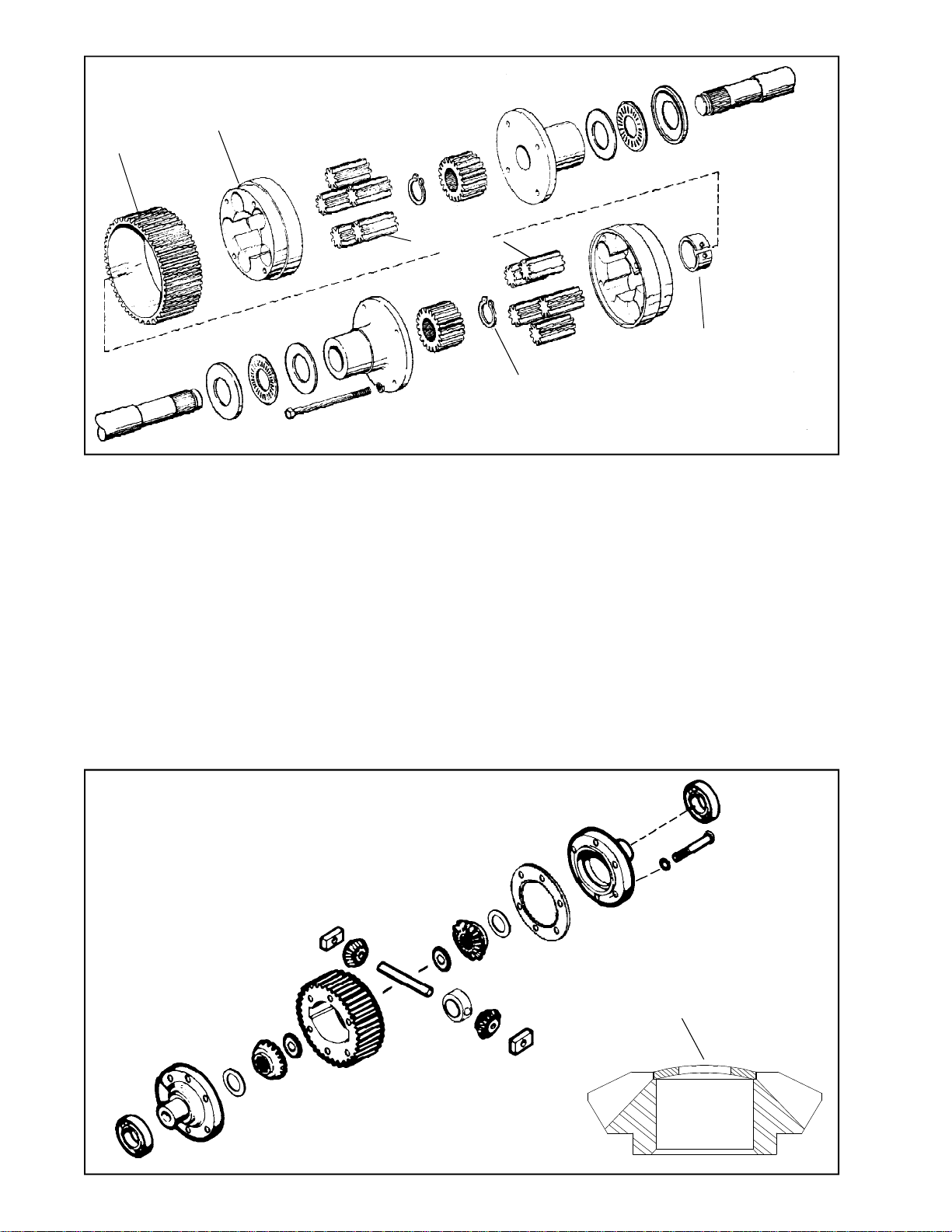
BODY CORES
Main Menu
Main Menu
RING GEAR
PINION GEARS
SPRING
(ONLY OLDER UNITS)
SNAP RING
"DUO-TRAK®"
*DUO-TRAK is the trademark of a patented limited slip differential designed by Illinois Tool Works.
The Model 2600 transaxle has the unique customer option of a semi-locked differential. This system acts like
a locked differential until the torque at the axle exceeds 50-70 ft./lbs. At this point it acts like a regular
differential. Using the following procedure, you can check for proper condition of this optional unit used on a
few 2600 models not all units.
1. Lift the rear of the tractor up so both tires are off the ground. Rotate one tire while in neutral the other
tire should rotate the same direction. If not, disassemble the unit. If it does proceed to step 2.
2. Lock one axle or wheel assembly so it can not turn.
3. Using a torque wrench and socket on the other axle, turn in a clockwise rotation noting the break away
point. It should be between 50-70 ft. lbs. (68 - 95.2 NM).
4. If the torque is low, you will need to split the ring gear and carrier. Remove any shim between the two
halves. If you do not find a shim, you will need to replace the spacer block. (see Illustration)
5. Re-assemble and check for proper break away torque as listed above. Breakaway should not exceed
70 ft./lbs (95.2 NM).
BELLEVILLE WASHER
ORIENTATION
90
Page 93
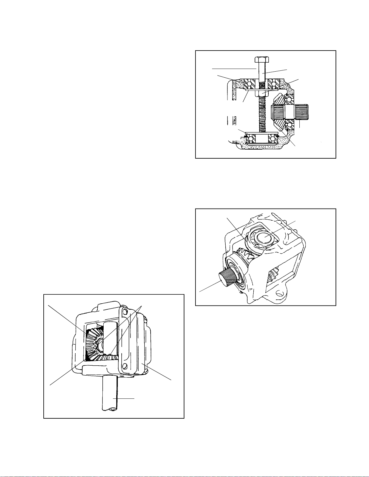
CHAPTER 9. DRIVES
Main Menu
Main Menu
This section relates to service of all Right Angle and T-box drives ACCEPT 1100 Series IN NEXT SECTION.
A. GENERAL
1. Prior to removing the assemblies, examine the
following items that may have failed causing
the right angle drives to appear inoperative.
2. Drive belts: Inspect for breaks, tension, oil or
grease saturation and inoperative tightening
devices.
3. Pulleys: Tighten retaining screws. Examine for
sheared keys.
4. Mower blade clutches and breakaway devices;
Some blades have slip type clutches that may
slip during operation and appear to be damaged
right angle drives. Shearing devices are also
used to absorb a damaging impact load if en
countered. Replace the clutch members or
shearing devices prior to removal of the right
angle drive if failure is noted.
5. Loose blade retaining nuts; Check torque and
tighten if required.
B. FINNED COVER RIGHT ANGLE DRIVE
1. Leaking lubricant. These drives do not have
oil seals or sealed ball bearings. If the unit is
to be serviced because of lubricant leakage, it
will be necessary to replace the ball bearings.
1/2" TO 3/4"
DIAMETER
BOLT
OUTPUT
SHAFT BALL
BEARING
LARGE WASHER TO
REST ON OUTER
BEARING
METAL PLATE TO
PROTECT LOWER
BEARING
MACHINE BOLT
APPROXIMATELY
4" LONG
BEVEL GEAR
b. Remove the output shaft bearing by using
a large machine bolt, washer and nut.
c. The input shaft bearing, input shaft and
bevel gear may now be driven out of the
housing. Use tool 670220. Press bearing
into housing to remove.
SNAP RING
OUTPUT SHAFT
AND BEARING
HEX NUT
INPUT SHAFT
DISASSEMBLY
2. Remove the cover and gasket and remove the
lubricant.
3. Different output shafts achieve a different
rotation by mounting a gear at the top or bottom
of the shaft.
DRIVEN BEVEL GEAR
DRIVEN BEVEL GEAR
IN LOWER POSITION
SNAP RINGS
FINNED COVER
OUTPUT SHAFT
INPUT SHAFT
d. The top ball bearing in the blind end of the
housing, is removed by either heating the
housing on a hot plate or tapping the housing
on the outside with a mallet.
a. If the driven bevel gear is on the bottom,
remove the snap ring on the output shaft
and pull out the output shaft.
91
Page 94
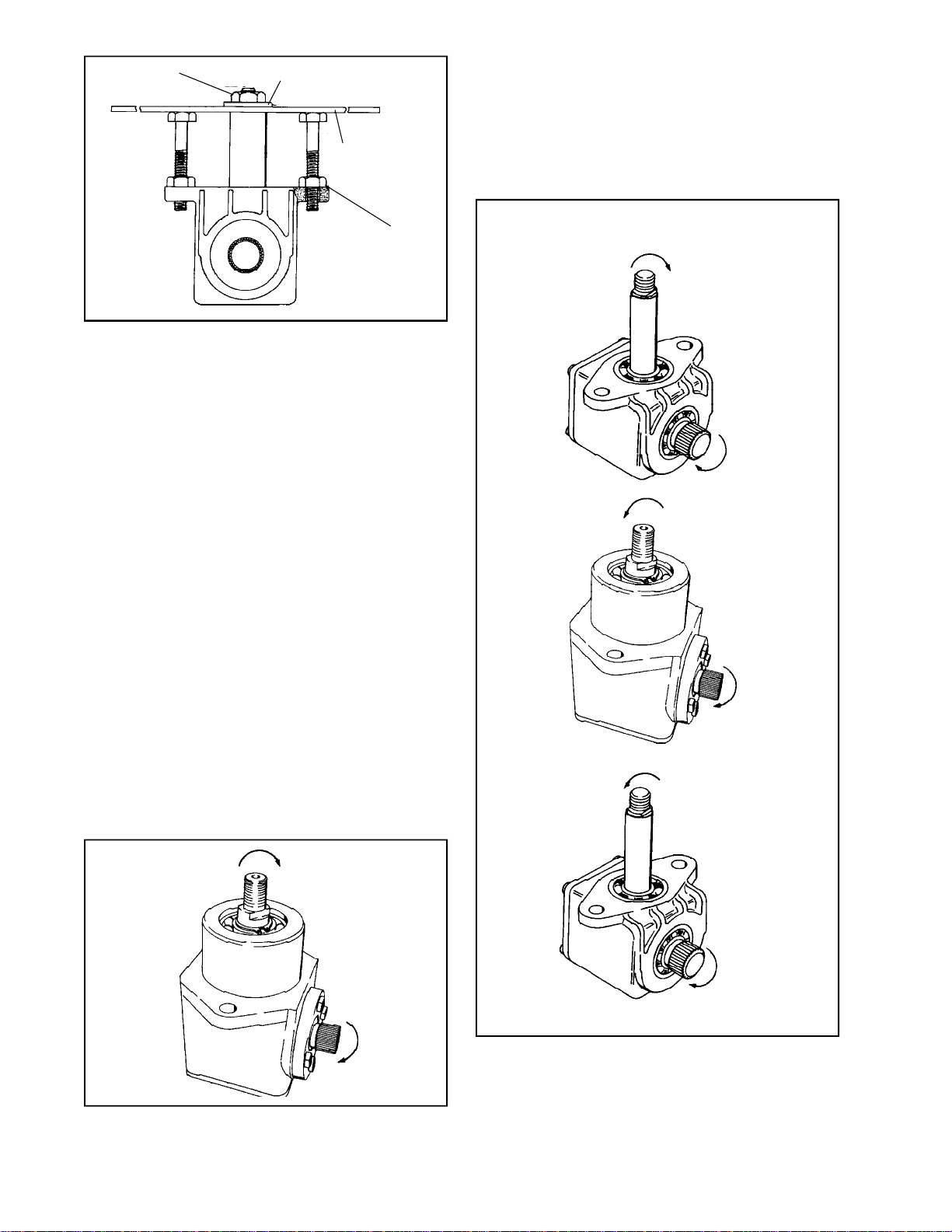
NUT
Main Menu
Main Menu
WASHER
MOWER BLADE
APPLY SMALL
AMOUNT OF GREASE
BETWEEN NUT AND
MOUNTING SURFACE
CW
e. Right angle units with the driven bevel gear
at the top will have to be disassembled as
illustrated above. The output shaft is larger
in diameter inside than outside. When the
out put shaft is pulled out the bearing will
also be removed.
INSPECTION
Clean all parts in cleaning solvent. Examine for wear
or damage and replace as needed. Use care when
handling ball bearings. See Chapter 11, Bushing and
Bearing Service.
REASSEMBLY
Assemble in reverse of the disassembly instructions.
It is important that only ball bearings with snap rings,
be used for the input shaft and top output shaft bearing.
Use tool for driving in bearings. In the event bearing
bore is tight in housing, heat housing on a hot plate.
Place a steel plate on the hot plate and rest housing
on steel plate. DO NOT OVERHEAT. Work rapidly
after removing housing from hot plate. Use care to
prevent burns.
LUBRICATION
LEFT HAND
RIGHT HAND
CW
CCW
CW
See Section 2. Lubrication Chart.
These are examples of directions of drive units.
92
CCW
RIGHT HAND
CW
LEFT HAND
CW
RIGHT ANGLE DRIVE MOVEMENTS
CW
Page 95
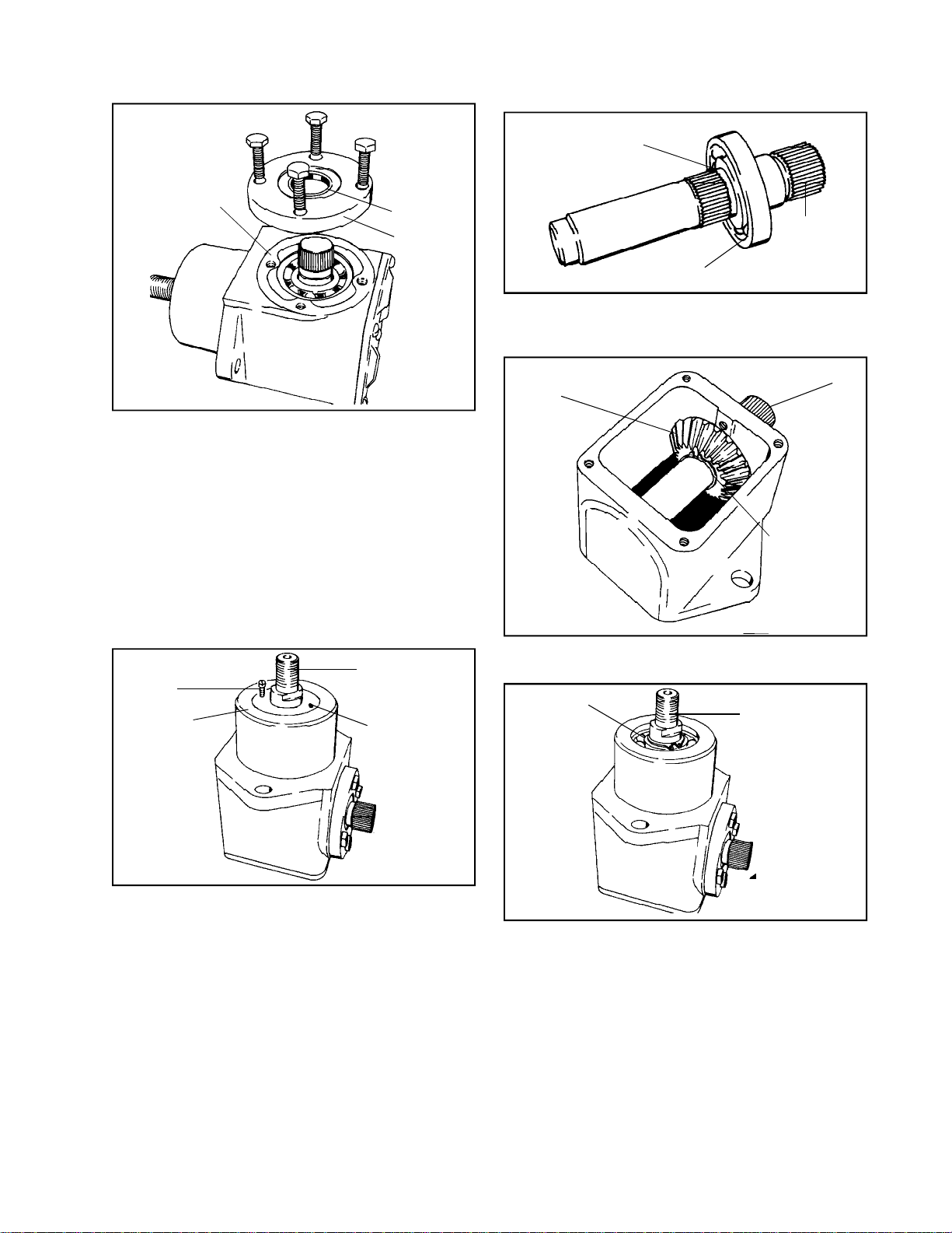
C. SMOOTH COVER RIGHT ANGLE DRIVES
Main Menu
Main Menu
DISASSEMBLY
SERVICE
GASKET
SEAL
COVER
Leaking lubricant: Correct lubricant leakage by
replacing the seals at the input and output shaft
as described above.
1. Input shaft seal replacement: Remove four
screws and the cover. Replace the seal by
driving in squarely so that it is .040'’ to .050'’
below flush. Use tool 670293 to protect the
seal when replacing the cover and seal assembly
over the input shaft. Place the seal sleeves
on the shaft and coat with oil. Slide the sealed
retainer over the sleeve. Tighten the seal retainer
screws and remove the sleeve.
SHEET METAL
SCREW
SEAL
OUTPUT SHAFT
HOLE IN SEAL
1. Remove the cover, gasket and lubricant.
BEARING AT INNER EDGE OF
MACHINED SURFACE
INPUT
SHAFT
BALL BEARING
2. If the unit is built with the bevel gear on the input
shaft toward the cover, remove the snap ring on
the input shaft from the groove.
DRIVING BEVEL
GEAR
INPUT SHAFT
SNAP RING
3. Remove four screws and the cover and seal
assembly.
SNAP RING
OUTPUT SHAFT
2. Output shaft seal replacement. Remove the
seal by punching two small holes in the seal
with an awl, as close to the outer edge of the
seal as possible and opposite each other. Use
care when making holes in seal so that ball
bearing underneath is not damaged. Do not use
a drill. Insert sheet metal screws into the holes
and pull on the screws to remove the seal.
Long screws may be turned in until they contact
the outer race of the ball bearing and turned to
lift out the seal. Place seal sleeve 670293 on
the shaft, lubricate generously with oil and slide
on the seal. Drive the seal into the housing
until it is flush with the bottom of the housing.
Use driver.
4. Remove the seal at the output shaft.
5. Remove the snap ring on the output shaft and tap
it with a mallet on the outside end to drive it and
the inner ball bearing, out of the housing. Remove
the out put end ball bearing by driving it out from
the inside.
93
Page 96
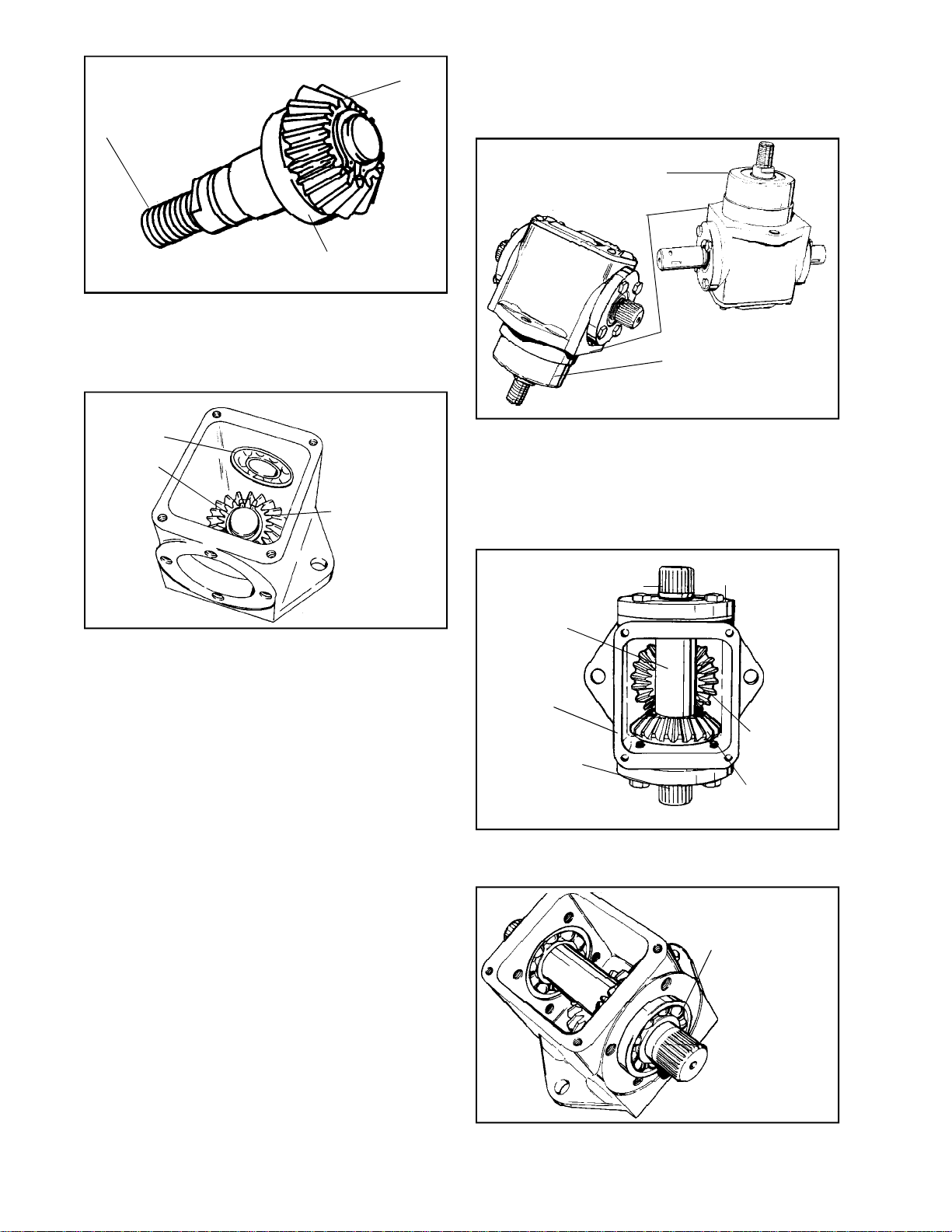
BEVEL GEAR
Main Menu
Main Menu
OUTPUT SHAFT
BALL BEARING
6. Remove the input shaft from the ball bearing, with
an arbor press. Always support the inner race when
removing and replacing the input shaft into the ball
bearing. Use tool 670293 to support the inner ball
bearing race.
INSIDE INPUT
BEARING
SNAP RING
DRIVEN BEVEL
GEAR ON OUTPUT
SHAFT
D. “T” DRIVE SERVICE
1. Before removing “T” Drive from equipment, be
sure to scribe marks at one mounting hole to
in sure correct reassembly.
"T" DRIVE WITH DIFFERENT INPUT AND
OUTPUT ENDS OF INPUT SHAFT
DRIVE MODEL
NUMBER
"T" DRIVE WITH IDENTICAL
INPUT AND OUTPUT ENDS
OF INPUT SHAFT
2. To disassemble “T” Drive, remove self-tapping
screws and housing cover and clean grease
from internal area. Note and mark near the
casting gasket surface on the side where the
beveled in put gear is located. To switch the
“T” 180o will result in output shaft opposite
rotation.
7. The ball bearing that supports the inner end of the
in put shaft is removed by holding the housing in
the hand and tapping the housing sharply on the
outside with a soft mallet behind the bearing. It
may at times be necessary to heat the housing to
remove this bearing.
INSPECTION
Clean all parts in cleaning solvent. Examine for wear
or damage and replace as needed. Use care when
handling ball bearings. See the Chapter on Bushing
and Bearing Service.
REASSEMBLY
Assemble the unit in reverse of the disassembly. When
building up the units it is important to install the correct
input shaft, and identify it with the correct cover, if
there is any identification on the cover, either R.H. or
L.H.
LUBRICATION
IF INPUT END OF SHAFT
OTHER END IS OUTPUT END
INPUT SHAFT
HOUSING
IF INPUT END OF
SHAFT OTHER END IS
OUTPUT END
BEARING CAP AND
SEAL RETAINER
OUTPUT
SHAFT BEVEL
GEAR
INPUT SHAFT
BEVEL GEAR
3. Remove capscrews and both retainer cap and
seal assemblies. Separate and discard oil seals
and gaskets.
BEARINGS ARE
SLIP FIT ON BOTH
INNER AND OUTER
RACES
See Section 2. Lubrication Chart.
94
4. Press input shaft ball bearings out of the housing
with fingers. If they stick, tap lightly using a
drift punch around the outer race.
Page 97
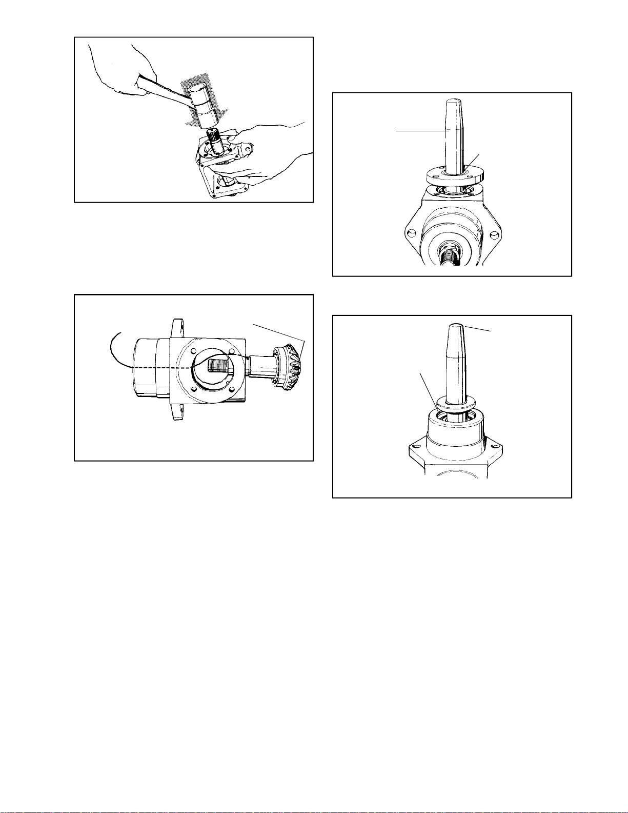
HOLD GEAR WITH FINGERS,
Main Menu
Main Menu
THEN TAP ON END OF
SHAFT WITH MALLET TO
SEPARATE
5. Using a soft mallet, separate the input shaft
and gear. A slight press fit holds a spline surface
on the shaft in a spline of the gear.
6. Remove and discard the output shaft oil seal.
Do not scratch shaft. Remove and discard snap
ring. Tap the shaft into the housing, using a
soft mallet.
TO REMOVE GEAR
REMOVE SNAP RING
REMOVE SNAP
RING
10. Press shaft, bearing and gear assembly into
housing until outer bearing race bottoms in
retaining cavity.
11. Install outer bearing and new snap ring.
USE THE PROPER
SIZE SEAL
PROTECTOR
ALWAYS REPLACE
OIL SEALS
12. Install new oil seal, using seal sleeve No. 670293
and driver until seal is flush with housing.
POSITION OIL SEAL
THEN USE SEAL
DRIVER TO SEAT
SEAL SQUARELY TO
THE PROPER DEPTH
USE THE PROPER
SIZE SEAL
PROTECTOR
TO ALLOW SHAFT AND
BEARING TO DROP OUT
OF HOUSING
TO REMOVE BEARING
REMOVE GEAR, AND
PRESS BEARING
INNER RACE
7. If necessary, remove the snap ring to separate
the gear and bearing from the shaft. Hold the
gear and bearing in one hand and tap the end
of the shaft vigorously with a soft mallet.
8. Cleaning, Inspection and Repair
a. Clean all parts of grease, rust, or foreign
matters.
b. Dry all parts. Compressed air may be used
on all parts EXCEPT BEARINGS.
c. Check bearings for smooth rotation.
Lubricate.
d. Remove all burrs and scratches from shafts.
e. Check housing for cracks or pulled metal.
f. Replace all snap rings removed.
g. Replace all oil seals.
9. If separated, install inner ball bearing and bevel
gear on output shaft. Be careful of alignment.
Use of a press is preferable to tapping parts
together with a mallet.
13. Position input bevel gear in mesh with output
shaft bevel gear. Tap the input shaft into place
with a soft hammer. Use one hand to hold the
gear and shaft to dampen tapping blows. Be
sure gear is on the marked side of the housing.
14. Align shaft and insert ball bearing on each
bearing surface by hand.
15. Install new seals in retainer caps, using driver.
16. Using seal sleeve 670293 over the shaft serrated
ends, install new gaskets and bearing cap.
Tighten retaining capscrews to 8-11 ft. lbs.
17. Lubrication: See Section 2. Lubrication Chart.
18. Install gasket and cover and secure with self
tapping screws. Torque to 20-24 in. lbs.
19. Align scribe marks and install “T” Drive on
equipment.
95
Page 98
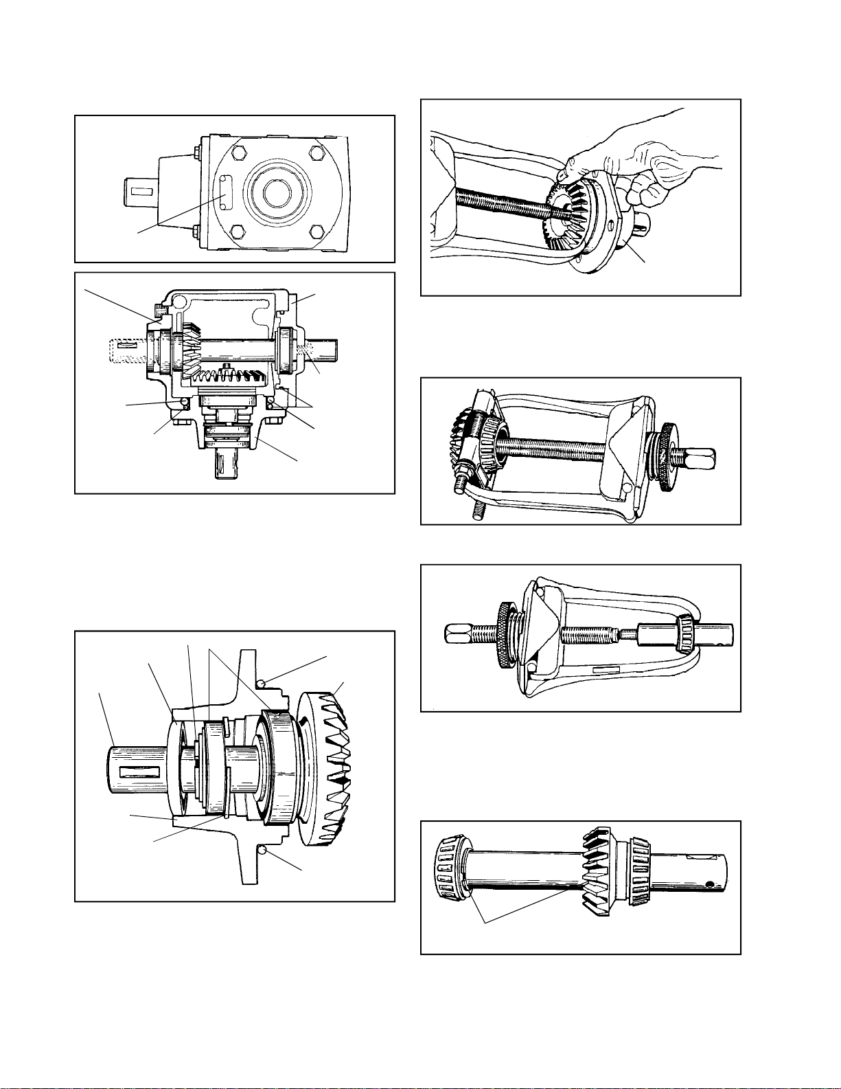
A. GENERAL
Main Menu
Main Menu
I.D. TAG
MAIN HOUSING
RING
1100 SERIES
CAP
OPTIONAL
VENT
"O" RING
CAGE
3. To disassemble the input cage assembly, first
remove the nut and washer that holds the large
keyed gear onto the shaft. With an outside puller,
if necessary, remove gear. Roller bearings will
be attached.
"O" RING
RING
CAGE
The 1100 series angle drive is a heavy duty gear
box used with larger equipment with a larger H.P.
rating up to 20 H.P. This unit is of cast iron
construction for strength and tapper roller bearing
for longer life. This unit can be either right angle
drive with right or left handed rotation, or a “T” drive.
Disassembly and reassembly are the same.
B. DISASSEMBLY
SNAP RING
SEAL
SHAFT
CAGE
BEARING ASSEMBLY
"O" RING
GEAR
*4. Remove bearing from gear by using a bearing
splitter and puller.
5. Remove shaft out of cage.* Remove roller
bearing with outside puller toward threaded side.
Remove snap ring.
6. To remove races, simply tap out with punch
and hammer. The large snap ring will be left in
cage when all parts are removed.
96
SNAP RING
"O" RING
1. Clean and check all shaft ends before removing
cap and cage assembly.
2. Remove the 4 input cage bolts and remove
input cage, assembly will follow.
SNAP RINGS
7. Remove the output cap and assembly will follow.
*When roller bearings are removed with puller, discard,
do not reuse. Also discard races.
Page 99
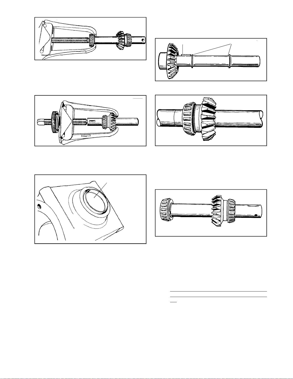
D. REASSEMBLY
Main Menu
Main Menu
It’s very important when assembling this unit that
all new seals and “O” rings be used.
8. To disassemble the output shaft assembly*,
first remove the bearing that is located under
cap on shaft, by using an outside puller.
CAUTION: Do not hook puller on snap ring.
9. Remove snap ring.
10. On other end, use the same puller and remove
both the keyed gear and bearing at the same
time.
11. Remove snap ring.
SOFT PLUG
WOODRUFF KEY
1. Replace snap rings on the output shaft. Press
keyed gear on, if necessary.
2. When pressing roller bearings into place with
press, make sure inner bearing race is used.
NOTE: Service bearings in this unit may have
a shim in the box along with a new outer race.
When pressing the bearing next to the gear,
place shim if present, for that bearing and race
next to the gear first, then the bearing.
SNAP RINGS
12. To remove 1-3/4'’ soft plug, simply tap out of
case. Discard old plug.
13. To remove races, simply tap the race out of
the cap and pry crush ring out. The other race
can be tapped out with punch and hammer. If
unit is not equipped with plug, very carefully
pry race and crush ring out of cap and discard.
C. INSPECTION
Clean all parts in cleaning solvent. Examine for
wear or damage and replace as needed.
*When roller bearings are removed with puller. Discard,
do not reuse. Also discard races.
3. Install the other bearing that fits into the cap
without shim. Discard the shim.NOTE: There
may be shims in the service bearing kit. Only
the bearings next to the gears may need a shim
only if the shim is in the kit.
4. The race that is used with roller bearing on the
gear side, mounts into the case. Press carefully
until seated.
NOTE: Make sure that all races and roller
bearings are kept together as provided in the
kit.
97
Page 100
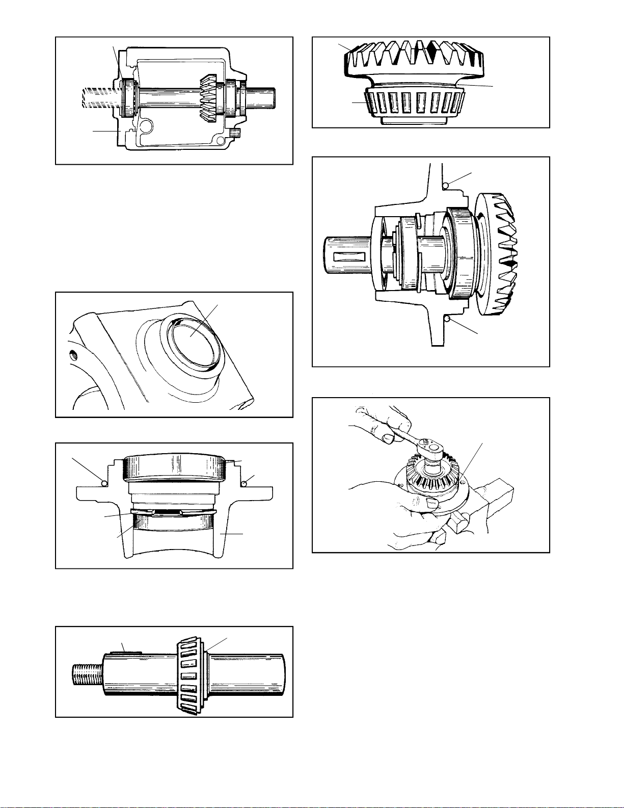
CRUSH RING
Main Menu
Main Menu
GEAR
BEARING
SHIM
IF REQUIRED
CAP
5. Before installing the cover, install new crush
ring into cover first. Place new race up to ring.
To properly set up the output shaft preload,
place shaft into box, place cover over shaft
without case/cover shim and “O” ring. Tighten
and torque the 4 bolts to 200 in. lbs. at 50 inch
pound increments.
6. Remove cover and place new case/cover shim
in place with new “O” ring and torque to 200 in
lbs. at 50 inch pound increments.
SOFT PLUG
7. To reinstall 1-3/4'’ soft plug, tap in carefully
with lip up, until 1/16'’ below flush is achieved.
"O" RING
BEARING
RACE
"O" RING
12. Press large shim and new large roller bearing
on to gear using inner bearing race.
"O" RING
"O" RING
13. Place shaft into proper position in cage, push
gear with bearing onto shaft.
ROTATE CAGE
WHILE
TIGHTENING
NUT
SNAP RING
BEARING RACE
98
CAGE
8. To assemble the cage assembly, place the large
snap ring in its mounting area in cage. Press
small race to snap ring from the outside.
9. Press large race into cap from back side.
WOODRUFF KEY
SNAP RING
10. Place small snap ring on shaft.
11. Press roller bearing on shaft to back side of
snap ring. Do not use shim. Install woodruff
key.
14. To achieve proper pre-load on bearings, place
the outboard side of shaft in protected vice.
Begin to tighten nut on gear side, while turning
cage until a very slight drag is achieved on the
cage housing with no end play. Parts must spin
freely.
15. After loading to the bearing is done, place new
“O” ring around the outer diameter of cage and
position in case. Reinstall bolts, tighten and
torque to 200 in. lbs.
16. To install seals, use a 1'’ seal protector. Position
seals so that it is .100 below flush.
F. LUBRICATION
After assembly, fill with 1 pt. E.P. 90 gear oil.
 Loading...