

Page 1
TecumsehPower
TM
Operator’s Manual
LH318EA (HM80-90)
LH358EA (HM100)
OH195EA/OH195EP
OH318EA
Four-Cycle Engine • Horizontal Crankshaft • Air-Cooled
Table of Contents
IMPORTANT NOTICE! Safety Definitions ........................................ ii
I. General Safety Precautions..............................................................1
II. How to Get Service...........................................................................4
III. Oil and Fuel Specifications ...............................................................5
IV. Before Starting Your Engine..............................................................6
V. Starting Your Engine .......................................................................10
VI. Stopping Your Engine and Short-Term Storage ..............................18
VII. Transporting Your Recreational Vehicle..........................................18
VIII. Maintenance ...................................................................................18
IX. Storing Your Engine ........................................................................25
X. Preventing Forest, Brush and Grass Fires .....................................27
XI. Maintenance Intervals.....................................................................28
California & US EPA Emission Control Warranty Statement...........36
Emission Control System Warranty ................................................37
XII. Warranty Information ......................................................................38
Visit our web site at www.TecumsehPower.com
Register Your Tecumseh Engine
Maintenance Tips
Parts Look-Up System
Great Tecumseh Apparel
Nearest Authorized Tecumseh Servicing Dealer Location
LOG ON!
181-1269-14
(English) 1/01/08
Page 2

I. Safety Definitions
WARNING
WARNING
Statements in this manual preceded by the following words
and graphics are of special significance:
!
WARNING
Or
WARNING
WARNING indicates a potentially hazardous situation
which if not avoided, could result in death or serious injury.
CAUTION
I. Use this Engine Only in Approved
Applications
Tecumseh Powersport engines are designed specifically for
non-competitive recreational vehicle applications such as
fun-karts, mini-bikes and ATV’s. This engine is not
designed or approved for aircraft, go-peds or any racing
applications. Since not all applications of this engine can be
anticipated, contact your nearest Authorized Tecumseh
Servicing Dealer. Find them on our website at
www.TecumsehPower.com or call Tecumseh Power
Company at 1-800-558-5402 for more information or if you
have questions about a particular application.
Use of this Power Sport engine in nonapproved applications may lead to
serious injury or death.
Indicates a potential situation which if not avoided, could
result in equipment or property damage.
NOTE
Refers to important information and is placed in italic type.
It is recommended that you take special notice of all items
discussed on the next three pages and wear the
appropriate safety equipment.
Before operating this engine it is your responsibility to read
this Operator’s Manual. Follow these basic rules for your
personal safety:
• Keep this manual handy at all times for future
reference.
• Read it carefully and familiarize yourself with
operating, maintenance, components and safety
instructions.
II. Notice Regarding Emissions
NOTE
Engines which are certified to comply with California and
U.S. EPA emission regulations for SORE (Small Off Road
Equipment), are certified to operate on regular unleaded
gasoline, and include the following emission control
systems: (EM) Engine Modification and (TWC) Three-way
Catalyst (if so equipped).
II. Special Information for Users
Installing an Engine
If you purchased this engine
separately with the intention of
installing it on a recreational vehicle, ensure that the vehicle
is designed or is retrofitted to be used specifically with this
Tecumseh Power Sport engine. If you use an improper, nonapproved and/or wrong sized engine, there is a potential for
serious injury or death from:
• operation at unsafe speeds or a runaway vehicle,
• improper fit and operation of guards, electrical
wiring, throttle cable, clutch, torque converter, etc.
III. Engine Model Applications
This manual applies to the following Power Sport Engine
Models:
• LH318EA (HM80-90), LH358EA (HM100)
• OH195EA/OH195EP
• OH318EA
III. Tecumseh Contact Information
For engine adjustments, repairs or warranty service not
covered in this manual, contact your nearest Authorized
Tecumseh Servicing Dealer. Find them on our website at
www.TecumsehPower.com or call Tecumseh Power
Company at 1-800-558-5402.
The trademarks TECUMSEH® and the DESIGN (Native American Head logo) are registered trademarks ofTecumseh Products
Company and are used by Tecumseh Power Company under license from Tecumseh Pr oducts Company. Tecumseh Power Company
is no longer owned by Tecumseh Products Company nor is it associated or affiliated in any way with Tecumseh Products Company.
Tecumseh Power Company
Page ii Power Sport Recreational Application Operator’s Manual 181-1269-14
©Copyright 2006
Page 3
I. General Safety Precautions
B. Avoid Gasoline Fires
!
WARNING
Read equipment manufacturer’s manual and this
material thoroughly before using this engine. Failure to
do so can result in serious injury or death. Call Tecumseh
Power Company at 1-800-558-5402 or visit
www.TecumsehPower.com if you have any questions.
A. Avoid Carbon Monoxide Poisoning
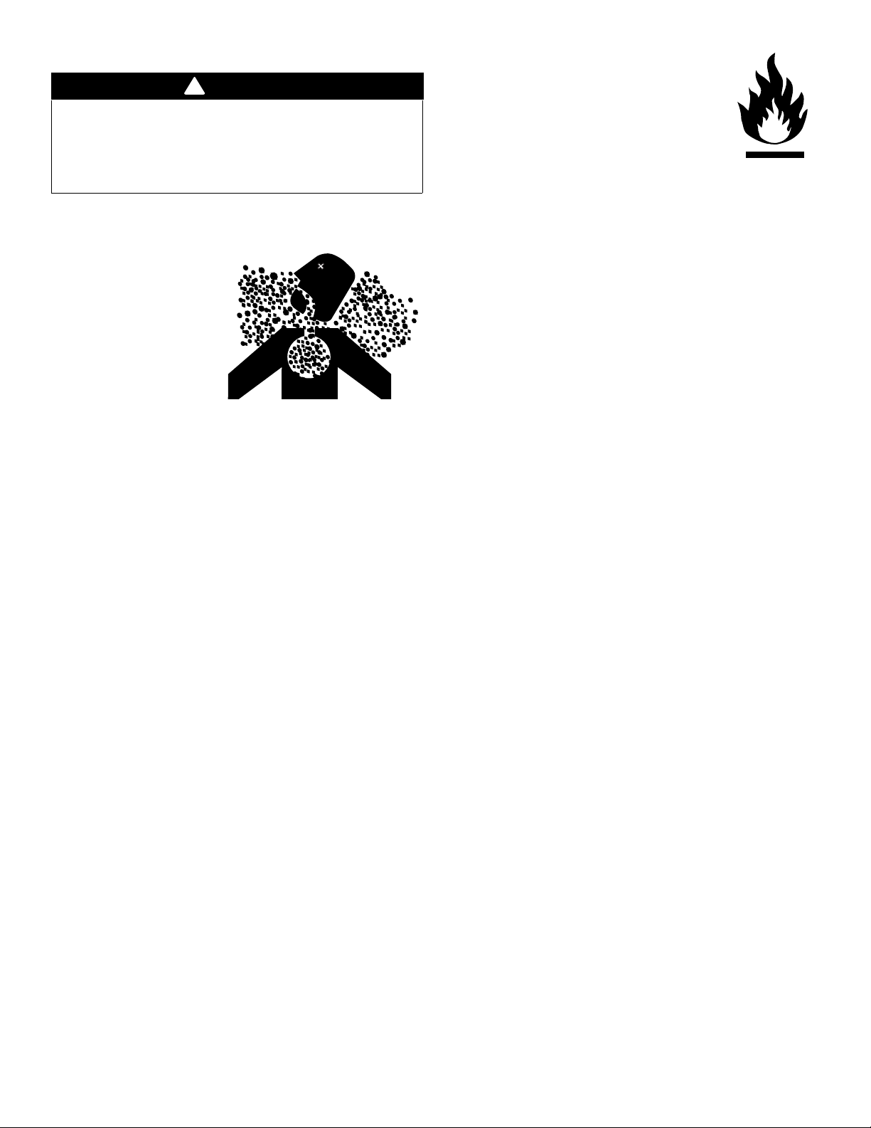
All engine exhaust
contains carbon
monoxide, a deadly gas.
Breathing carbon
monoxide can cause
headaches, dizziness,
drowsiness, nausea,
confusion and eventually
death.
Carbon monoxide is a colorless, odorless, tasteless gas
which may be present even if you do not see or smell any
engine exhaust. Deadly levels of carbon monoxide can
collect rapidly and you can quickly be overcome and
unable to save yourself. Also, deadly levels of carbon
monoxide can linger for hours or days in enclosed or
poorly-ventilated areas. If you experience any symptoms of
carbon monoxide poisoning, leave the area immediately,
get fresh air, and SEEK MEDICAL TREATMENT.
To prevent serious injury or death from carbon monoxide:
• NEVER run engine indoors. Even if you try to
ventilate engine exhaust with fans or open windows
and doors, carbon monoxide can rapidly reach
dangerous levels.
Gasoline (fuel) vapors are highly
flammable and can explode. Fuel vapors
can spread and be ignited by a spark or
flame many feet away from engine. To
prevent injury or death from fuel fires,
follow these instructions:
• NEVER store engine with fuel in fuel tank inside a
building with potential sources of ignition such as
hot water and space heaters, clothes dryers,
electric motors, etc.
• NEVER add fuel with engine running.
• NEVER start or operate the engine with the fuel fill
cap removed.
• Allow engine to cool before refueling.
• NEVER fill fuel tank indoors or in an enclosed area
such as a garage, barn shed, etc. Fill fuel tank
outdoors in a well-ventilated area.
• DO NOT smoke while refueling tank.
• Use only an approved red GASOLINE container to
store and dispense fuel. Tecumseh recommends
purchasing gasoline in containers with a capacity of
2.5 gallons or less. Small containers are easier to
handle and help eliminate spillage during refueling.
• DO NOT pour fuel from engine or siphon fuel by
mouth. To empty the fuel tank see "I. Draining Fuel"
instructions on page 26.
• NEVER run engine in poorly-ventilated or partially
enclosed areas such as barns, garages,
basements, carports, under dwellings, or in pits.
• NEVER run engine outdoors where engine exhaust
can be drawn into a building through openings such
as windows and doors.
181-1269-14 Power Sport Recreational Application Operator’s Manual Page 1
Page 4
C. Adult Supervision of Operation, Refueling
and Maintenance
The manufacturer of the recreational vehicle may provide
information about who is allowed to operate or ride in the
vehicle (see equipment manufacturer’s manual). Not
everyone who is allowed to operate or ride in the vehicle is
capable of safely and responsibly operating, maintaining
and/or fueling this Tecumseh Power Sport Engine.
Tecumseh recommends the following:
• An adult should fuel this engine. NEVER allow
children to refuel this engine. See "D. Filling Fuel
Tank" instructions on page 8.
• An adult should perform maintenance on this
engine. See "VIII. Maintenance" instructions on
page 18. Only allow children to perform
maintenance if an adult has determined they are
experienced and capable of such operation.
• An adult should start the engine. See "G. Avoid
Accidental Starts" instructions on page 3 and "A.
Engine Pre-Ride Checklist" instructions on page 6.
Only allow children to start the engine if an adult has
determined they are experienced and capable of
such operation.
Figure 1. DO NOT use Without Engine Shaft Guard
1
2
To avoid unsupervised operation of the recreational
vehicle, especially by children, NEVER leave the engine
unattended when it is running.
D. Stay Away from Rotating Parts
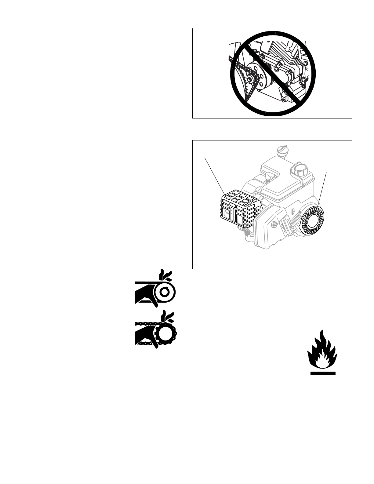
NEVER operate the engine with an
unguarded engine shaft. See Figure 1.
The equipment manufacturer attaches a
sprocket and chain or pulley and belt to
the engine shaft. If these parts are not
properly guarded, or if you are not sure
whether they are properly guarded, DO
NOT use your recreational vehicle;
contact the equipment manufacturer.
Hands, feet, hair, jewelry, clothing, etc.
can become entangled in rotating parts,
leading to serious injury or death. To
avoid serious injury or death, be sure the flywheel guard is
in place. See Figure 2.
E. Do Not Modify Engine
To avoid serious injury or death, DO NOT modify engine in
any way. Tampering with the governor setting can lead to a
runaway vehicle and cause the engine to operate at unsafe
speeds. NEVER tamper with factory setting of engine
governor.
P
O
T
S
1. Muffler Guard
2. Flywheel Guard
Figure 2. Typical Engine Guard Locations
F. Avoid Burns and Fire from Hot Surfaces
The muffler and other engine parts become extremely hot
during operation and remain hot after the engine has
stopped.
• To avoid severe burns on
contact, NEVER operate
the engine without the
muffler guard in place, see
Figure 2 and avoid hot
areas of the engine.
• To reduce the risk of fire
keep all materials that can
burn, including grass and leaves, away from muffler
and rest of engine. DO NOT operate, idle or park
the recreational vehicle in long dry grass or other
dry ground cover.
Page 2 Power Sport Recreational Application Operator’s Manual 181-1269-14
Page 5
G. Avoid Accidental Starts
To prevent accidental starting when working on equipment
always:
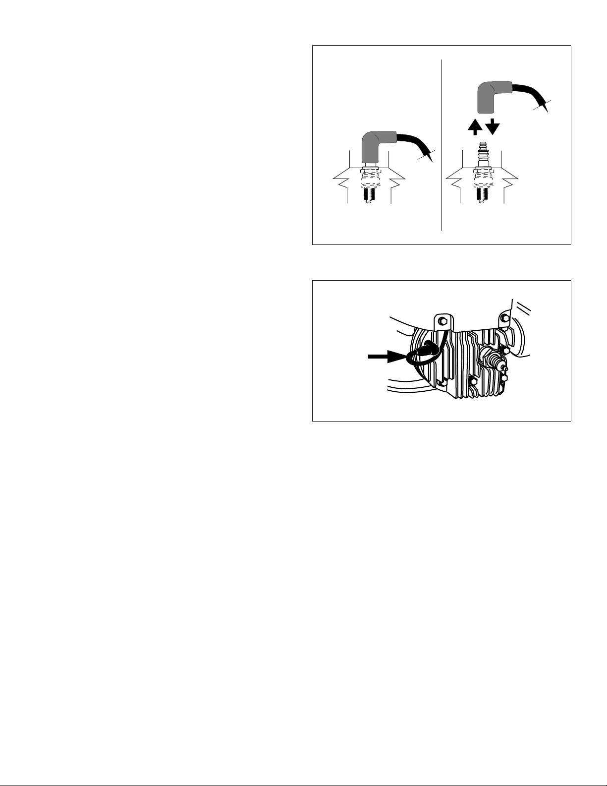
• Disconnect spark plug wire and keep it away from
spark plug. See Figure 3.
• Keep the disconnected spark plug wire
securely away from metal parts where arcing
could occur.
• Attach the spark plug wire to the grounding
post, if provided. See Figure 4.
• Disconnect battery at negative terminal first, if
engine is equipped with an electric starter.
• Turn off all engine switches.
• Remove ignition key, if provided.
H. Use Hearing Protection
Engine noise may cause hearing damage. Always wear
hearing protection when operating a recreational vehicle
engine.
Figure 3. Disconnecting/Connecting Spark Plug
Figure 4. Spark Plug Grounding Post
181-1269-14 Power Sport Recreational Application Operator’s Manual Page 3
Page 6

II. How to Get Service
For engine adjustments, repairs or warranty service not
covered in this manual, contact your nearest Authorized
Tecumseh Servicing Dealer. Find them on our website at
www.TecumsehPower.com or call Tecumseh Power
Company at 1-800-558-5402.
Visit our web site at
Register Your Tecumseh Engine
Maintenance Tips
Parts Look-Up System
Great Tecumseh Apparel
Nearest Authorized Tecumseh Servicing Dealer Location
A. Engine Identification Decal
www.TecumsehPower.com
LOG ON!
ENGINE
MODEL:
TECUMSEH POWER COMPANY
THIS ENGINE MEETS 1995-2005 CALIF & US EPA
PHI APPLICABLE EMISSION REGULATIONS FOR SI
SORE ENGINES
LV195EA
361540D
4TPXS.1951BB 195
EM
04015AA0001
2083
A sample decal located on your engine indicates your
engine’s model number, specification and the date of
manufacture (D.O.M.). Please look at the decal on your
engine and fill in this information in the spaces provided for
future reference. See Figure 5.
The Engine Identification
Decal includes engine life
specifications for the emissions-related useful life period of
your engine. This period relates to the emission
compliance life as certified by EPA and/or CARB. To find
the life period specification for your engine, please look on
your decal and find the letter enclosed by quotation marks
between the words MODERATE and LIFE PERIOD. Match
one of the following letters with the letter printed on your
decal. For example, OH195EA/OH195EP models are
designated as “C”125 hours, “B” 250 hours and “A” 500
hours. LH318EA (HM80-90), LH358EA (HM100) and
OH318EA models are designated as “C”250 hours, “B” 500
hours and ”A” 1000 hours.
B. Tecumseh Technician’s Handbooks
If you have a general understanding of internal combustion
engines and wish to repair and service your engine and/or
engine emission control systems yourself, a Technician’s
Handbook is available from your Authorized Tecumseh
Servicing Dealer. See Figure 6. This handbook covers
repairs and adjustments not covered within this Operator’s
Manual, and it is intended for individuals who have had
adequate training, experience and who practice proper tool
usage. Service procedures should be clearly understood
and practiced when servicing Tecumseh Power Sport
Engines. Order as part no. 695244A for
OH195EA/OH195EP and OH318EA models. Order as part
no. 692509 for LH318EA (HM80-90), LH358EA (HM100)
models.
SPEC:
D.O.M.
Figure 5. Engine Identification Label
TECHNICIAN'S HANDBOOK
OVERHEAD VALVE
4 -CYCLE
ENGINES
TECHNICIAN'S HANDBOOK
3TO11HP
4 - CYCLE
L- HEAD
ENGINES
Figure 6. Technician Handbooks
Tecumseh manufactures and is responsible only for the
engine used on this power equipment. If repair or service is
needed for anything other than the engine, contact the
service source recommended by the equipment
manufacturer.
Page 4 Power Sport Recreational Application Operator’s Manual 181-1269-14
Page 7
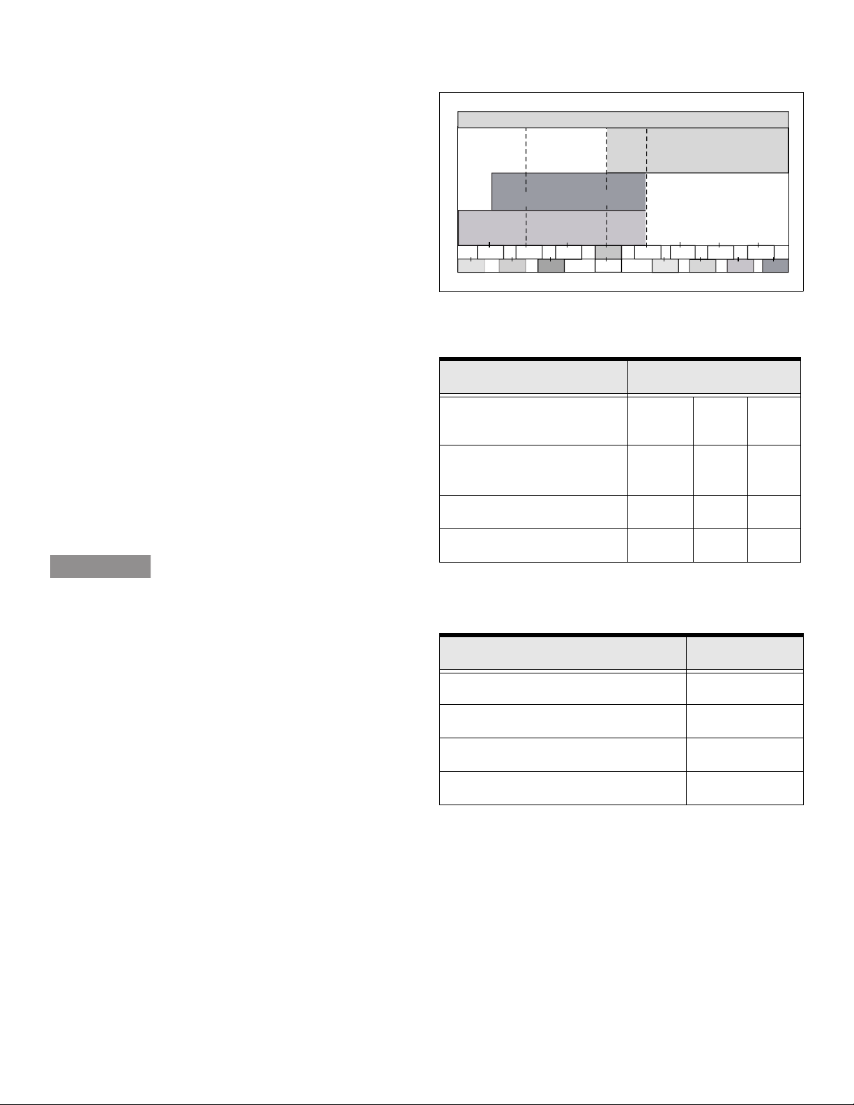
III. Oil and Fuel Specifications
32 F
O
A. Oil
To operate engine you need to use a clean, high quality,
detergent oil. For recommended engine oil, See Table 1.
NOTES
Be sure oil container is marked A.P.I. Service “SL/SJ”.
Using multigrade oil above 32 F (0 C) will increase oil
consumption. SAE10W40 is not recommended.
Oil sump capacities vary with each model. Tecumseh
special-formulated oils are available at your Authorized
Tecumseh Servicing Dealer. See Table 2.
B. Fuel
°°
-30 C
Table 1. Recommended Engine Oil
Tecumseh Recommended Oil Usage
Multi Grade
Tecumseh Part No.
730226A or SAE 5W30 or SAE 10
Synthetic
Tecumseh Part No.
730263 or SAE 0W30
O
O
0 F
-20 F
O
O
-20 C
-10 C
O
20 F
O
32 FO 32 F
O
0 C
O
O
40 F
10 C
Straight Grade
Tecumseh Part No.
730225A or SAE 30
O
60 F
20 C
80 F
O
O
O
O
100 F
O
40 C
O
30 C
Use unleaded regular, unleaded premium or reformulated
automotive fuel only. You may use gasoline containing the
following components identified. See Table 3.
• DO NOT use leaded fuel.
• Fuel must be fresh and clean. NEVER use fuel left
over from last season or stored for long periods.
• NEVER mix oil with fuel.
• DO NOT use fuel containing Methanol (Wood
Alcohol).
CAUTION
The use of alternative fuels such as E85
or E20 are not recommended for use in
Tecumseh engines. Alternative fuels with high alcohol
content can cause hard starting, poor engine performance,
and may cause internal engine damage.
NOTE
Damage and/or performance problems that will occur from
use of fuels, other than those listed in the Operator’s
Manuals will not be considered warranty.
Table 2. Oil Sump Capacities
Engine Model Units
Application
Ounces U.S.
Pints
LH318EA (HM80-90)
26 oz. 1-5/8 .78
LH358EA (HM100)
OH195EA/OH195EP 21 oz. 1-1/4 .62
OH318EA 26 oz. 1-5/8 .78
Table 3. Recommended Fuel Components
Liters
Fuel Component Percentage
Ethanol 10%
Grain Alcohol (“Gasohol”) 10%
MTBE (Methyl Tertiary Butyl Ether) 15%
ETBE (Ethyl Tertiary Butyl Ether) 15%
181-1269-14 Power Sport Recreational Application Operator’s Manual Page 5
Page 8
IV. Before Starting Your Engine
A. Engine Pre-Ride Checklist
WARNING
To avoid serious injury or death,
always complete both the engine and
equipment manufacturer’s pre-ride checklist before using
the engine. This engine should NEVER be used if you
identify a problem with any of the steps listed below.
Be sure the engine is turned off for steps 1 thru 4:
1. Fuel cap—Check that the anti-splash fuel fill cap is
securely in place.
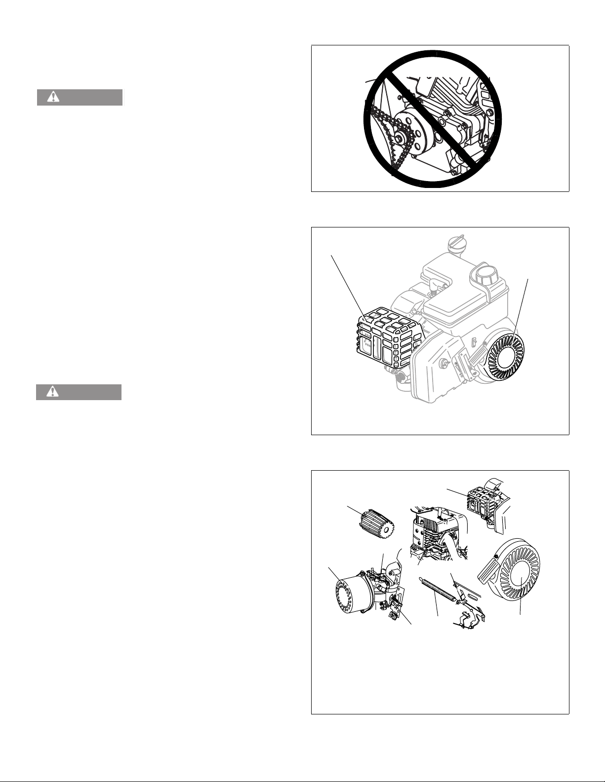
2. Guards—Check that all of the guards are securely in
place. NEVER operate the vehicle if you think there
may be a guard missing. Check with equipment manufacturer for a complete list of guards. See Figure 7 and
Figure 8. See "D. Stay Away from Rotating Parts"
instructions on page 2.
3. Debris—Check that engine, controls and guards are
free from debris, snow or ice. For debris removal areas,
see "B. Removing Debris From Engine" instructions on
page 20.
4. Throttle—With the engine off, check that the gas pedal
operates smoothly and returns to an idle position when
released.
WARNING
An adult should start the engine. Only
allow children to start engine if an
adult has determined they are experienced and capable of
such operation.
5. Idle speed—Be sure that operator is in place with the
brake engaged before starting the engine. Start the
engine and slowly release the brake. Check that the
vehicle does not move when the engine is idling. If it
does move at idle, stop the vehicle and shut off the
engine. The vehicle requires service and should not be
operated.
Figure 7. Incorrect Usage Without Engine Shaft Guard
1
2
P
O
T
S
1. Muffler Guard
2. Flywheel Guard
Figure 8. Engine Guard Locations
5
3
6. Engine stop switches—Check that the operator knows
where all engine stop switches are located. Check that
all engine stop switches immediately stop the engine.
For stop switch locations, see Figure 13 on page 8.
3
1
2
For questions about the pre-ride checklist for this engine,
contact your nearest Authorized Tecumseh Servicing
Dealer. Find them on our website at
www.TecumsehPower.com or call Tecumseh Power
Company at 1-800-558-5402.
1
1
4
1. Levers and Linkage
2. Cooling Fins
3. Air Cleaner Cover
4. Flywheel Guard
5. Muffler Guard
Figure 9. Debris Removal Areas
Page 6 Power Sport Recreational Application Operator’s Manual 181-1269-14
Page 9
B. Checking Oil Level
FULL
ADD
OK
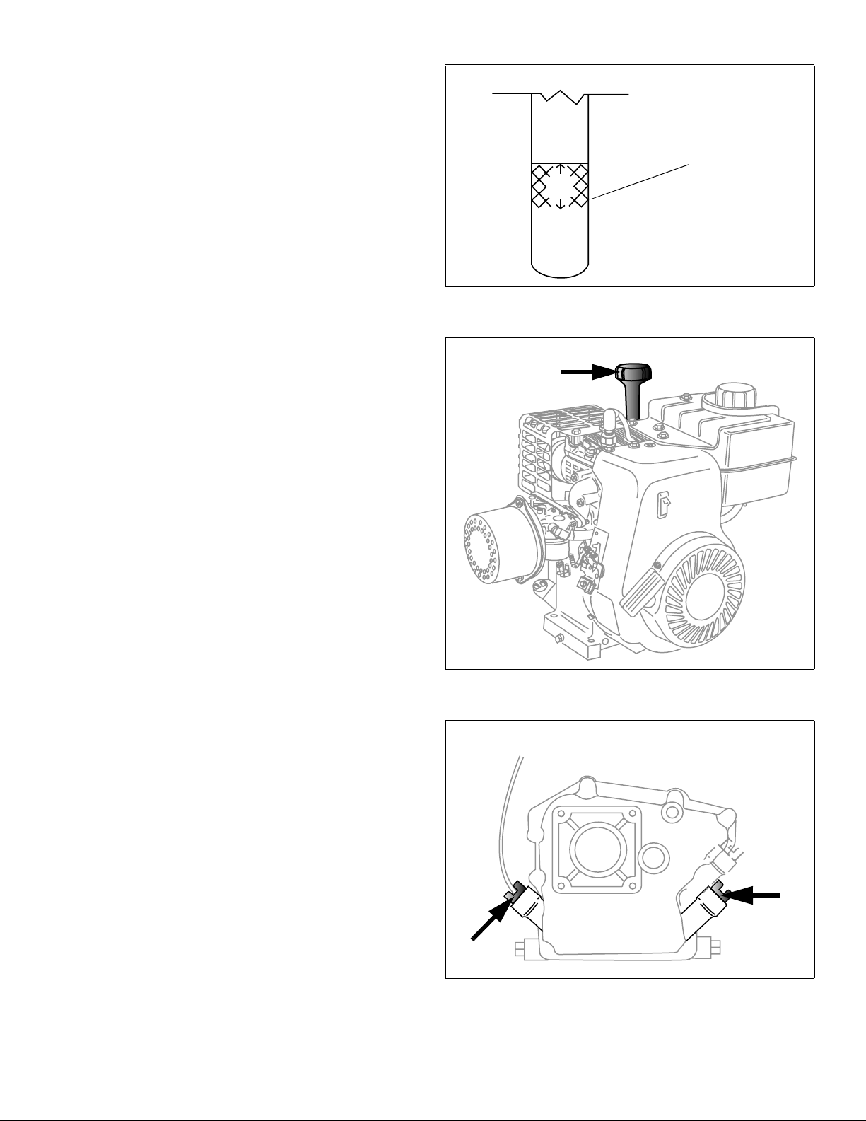
To avoid engine damage, it is important to:
• Check oil level before each use and every 5
operating hours.
• Keep oil level between “FULL” and “ADD” marks on
dipstick or to point of overflow on engines without
dipstick. See Figure 10.
• Be sure oil fill dipstick/plug is tightened securely.
NOTES
Do not overfill engine with oil. Doing so may result in
equipment malfunction or damage.
Do not allow oil level to fall below the “ADD” mark on
dipstick. Doing so may result in equipment malfunction or
damage.
Contact your Authorized Tecumseh Servicing Dealer for
Tecumseh Oil.
I. Oil Fill Dipstick
If your engine has an oil fill plug see "II. Oil Fill Cap Without
Dipstick (Oil fill Plug)" instructions.
1. Be sure engine is upright and level.
NOTE
Some Power Sport Engines are equipped with an oil fill
dipstick. See Figure 11.
2. Unscrew oil fill dipstick from oil filler tube and wipe clean.
Fill between
“Full” and
“ADD” marks
Figure 10. Engine Oil Level
3. Screw oil fill dipstick back into oil filler tube. Tighten securely.
4. Unscrew and remove oil fill dipstick from oil filler tube.
Note oil level. If oil reading on dipstick is below “ADD”
mark, slowly add oil to reach “FULL” level. See Figure
10.
5. Screw oil fill dipstick back into oil filler tube. Tighten securely.
6. Wipe away any spilled oil.
II. Oil Fill Cap Without Dipstick (Oil fill Plug)
If your engine has an oil fill dipstick see "I. Oil Fill Dipstick"
instructions.
1. Be sure engine is upright and level.
NOTE
All models in this manual may be equipped with optional oil
fill plug locations. See Figure 12.
2. Clean area around oil fill plug(s). See Figure 12.
3. Unscrew oil fill plug.
4. Add oil to overflow point, making sure to avoid spilling.
5. Screw oil fill plug back into oil fill hole. Tighten securely.
Figure 11. Possible Oil Fill Dipstick Location
Figure 12. Possible Oil Fill Plug Location(s)
6. Wipe away any spilled oil.
181-1269-14 Power Sport Recreational Application Operator’s Manual Page 7
Page 10
C. Engine Stop Switch
Climate Gu
ard
RUN
CHO
KE
!
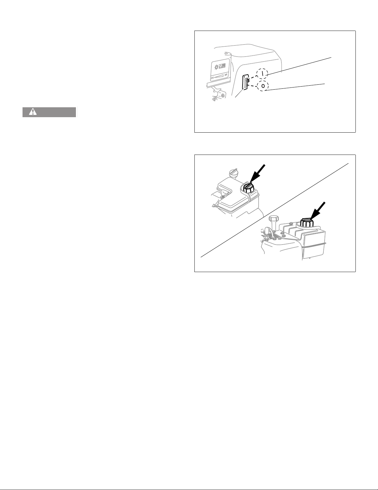
Power Sport Engines are equipped with an Engine Stop
Switch. This rocker switch is used to shut off the ignition
that supplies the spark plug with power. Pressing the
switch to the “OFF” position will turn the engine off when it
is running. This switch must be in the “ON” position or the
engine will not start. See Figure 13.
D. Filling Fuel Tank
1
2
3
WARNING
An adult should fuel this engine.
NEVER allow children to refuel this
engine. Gasoline (fuel) vapors are highly flammable and
can explode. Fuel vapors can spread and be ignited by a
spark or flame many feet away from engine. To prevent
injury or death from fuel fires, follow these instructions:
1. Stop engine and allow it to cool before refueling.
2. Be sure engine is outdoors and in a well-ventilated
area.
3. Clean area around fuel fill cap and remove anti-splash
fuel fill cap. See Figure 14.
1. ON Position
2. OFF Position
3. Switch
Figure 13. Engine Stop Switch
Figure 14. Possible Fuel Fill Cap Location(s)
Page 8 Power Sport Recreational Application Operator’s Manual 181-1269-14
Page 11
4. Using an approved red GASOLINE container, add fuel
slowly, being careful to avoid spilling. DO NOT overfill
fuel tank. Leave space in the tank to allow fuel to
expand without overflowing. See "B. Fuel" instructions
on page 5.
5. Replace anti-splash fuel fill cap securely and wipe up
spilled fuel before starting engine. If fuel is spilled DO
NOT start engine. Move machine away from area of
spillage. Avoid creating any source of ignition until fuel
vapors are gone.
NOTES
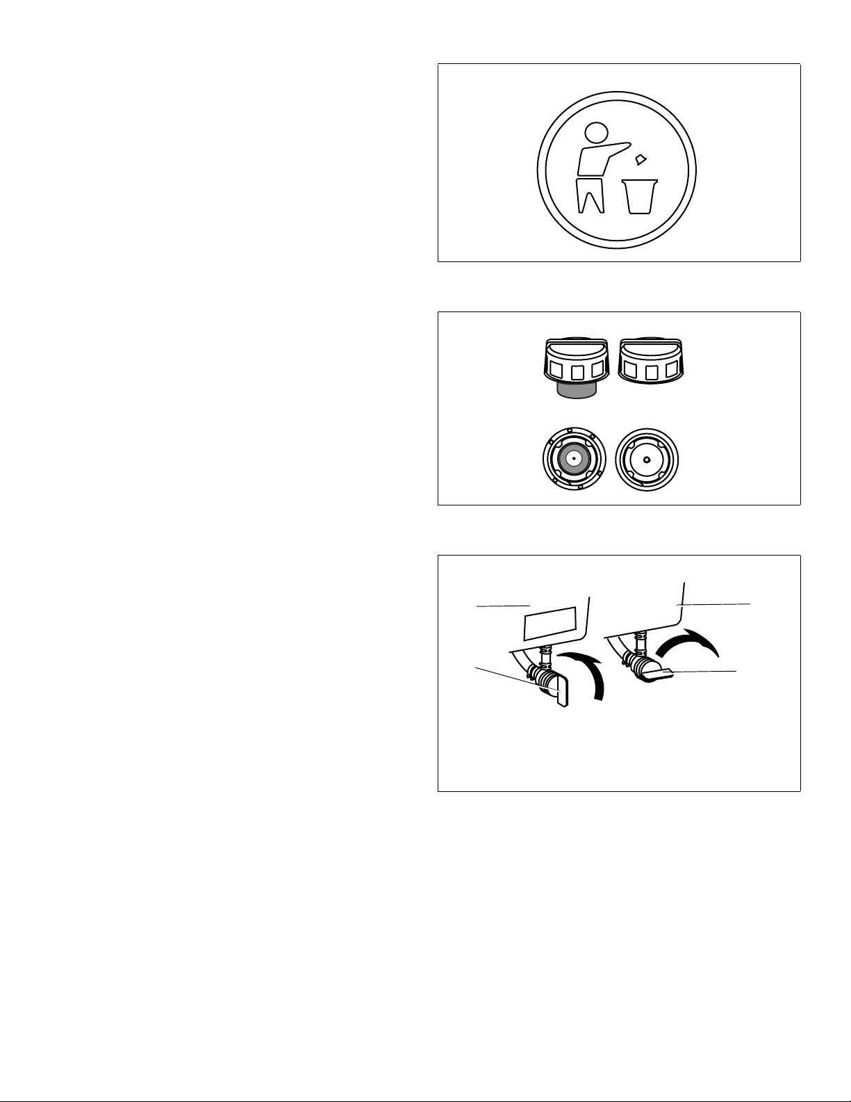
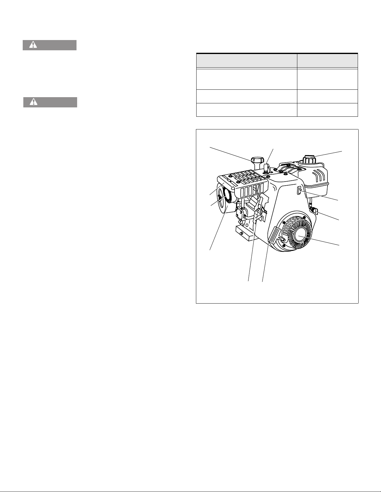
Remove and discard white plastic fuel tank insert, if
provided. See Figure 15.
Replace a damaged or missing gas cap only with a genuine
Tecumseh replacement anti-splash fuel fill cap. Failure to do
so may VOID YOUR WARRANTY. See Figure 16.
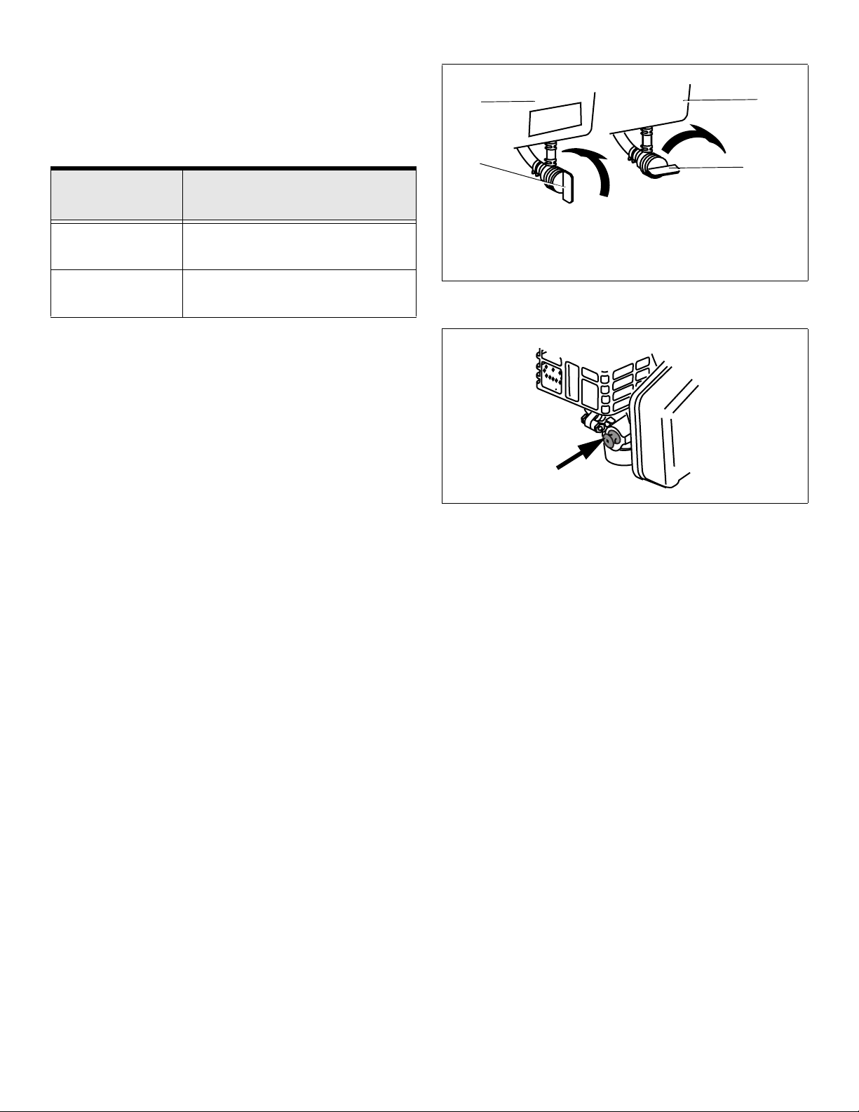
E. Optional Fuel Valve
Some engines are equipped with an optional fuel valve.
See Figure 17.
Figure 15. Fuel Cap Insert Disposal Symbol
Front View
1. Turn fuel valve counterclockwise to “OPEN” position.
2. Turn fuel valve clockwise to “OFF” position
NOTE
Always be sure fuel valve is in the “OFF” position after each
use. See Figure 17.
Bottom View
Figure 16. Possible Anti-Splash Fuel Fill Cap(s)
3
1
1. Fuel Valve in “OPEN” Position Shown
2. Fuel Valve in “OFF” Position Shown
3. Fuel Tank
Figure 17. Optional Fuel Valve
3
2
181-1269-14 Power Sport Recreational Application Operator’s Manual Page 9
Page 12
V. Starting Your Engine
WARNING
adult has determined they are experienced and capable of
such operation.
See "A. Engine Pre-Ride Checklist" instructions on page 6.
An adult should start the engine. Only
allow children to start engine if an
NOTE
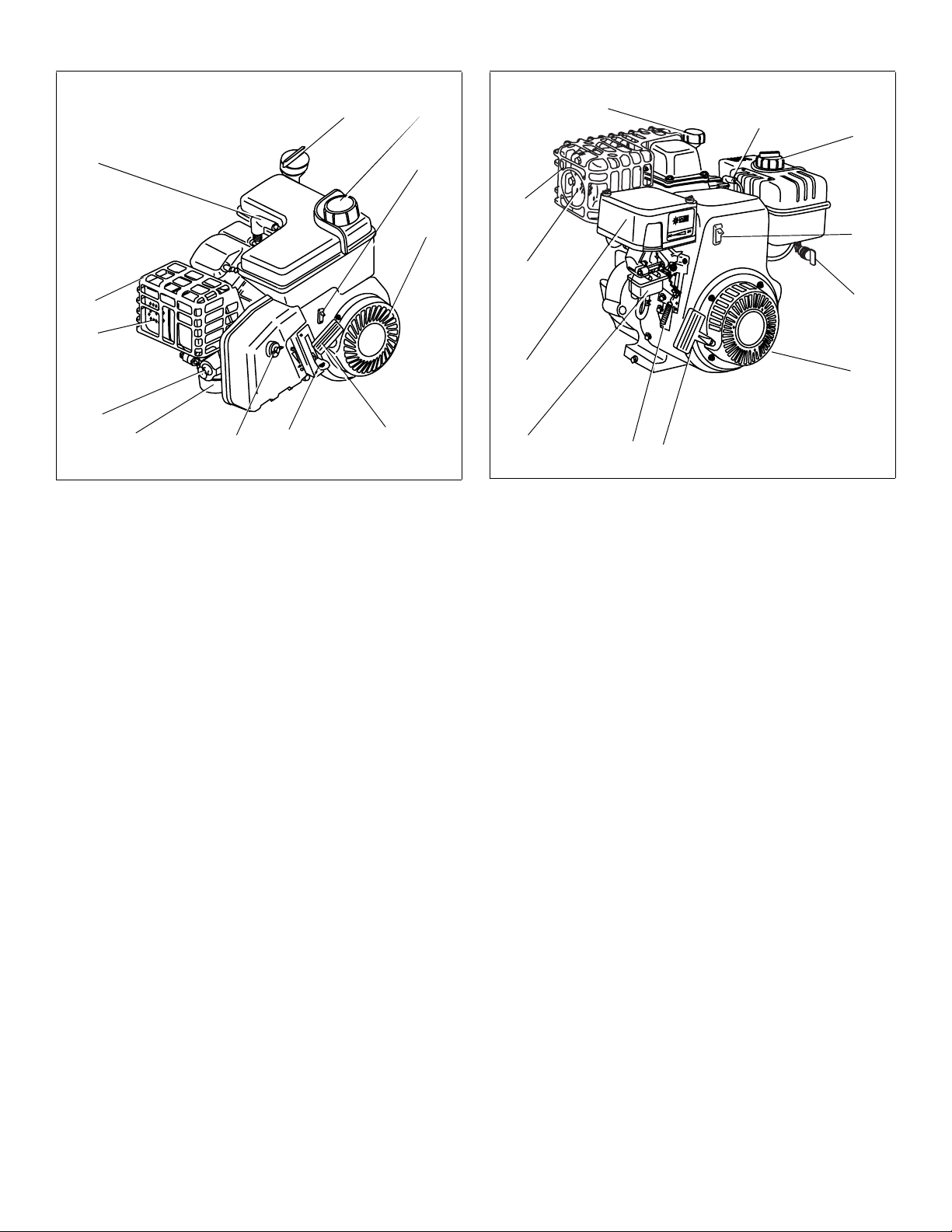
Only one of the following illustrations will apply to your
engine. See Table 4.
Table 4. Model Assemblies
If your engine model is a: Location:
LH318EA (HM80-90)
LH358EA (HM100)
See Figure 18.
WARNING
manual, contact your Authorized Tecumseh Servicing
Dealer. To avoid serious burn injuries or damage to your
engine, DO NOT attempt to start or troubleshoot this engine
in any other way. For example:
• DO NOT use starting fluid.
• DO NOT spray flammable vapors into carburetor or
onto air cleaner.
• DO NOT put flammable liquids into carburetor or
onto air cleaner.
• DO NOT operate engine or pull on starter rope with
spark plug removed. Fuel can spray from spark plug
hole and ignite.
• DO NOT apply throttle or gas pedal while starting.
This section contains starting instructions for several
different types of engines. In order to locate the instructions
that apply to your engine, first determine what type of
starter you have. If you have an electric starter
see "A. Engines with Electric Starters" instructions on page
12. If you have a manual recoil starter see "B. Engines with
Recoil Starters" instructions.
Item Descriptions
If you are unable to start this engine
after following instructions in this
OH195EA/OH195EP See Figure 19.
OH318EA See Figure 20.
6
5
4
3
7
1112
8
9
13
10
The item descriptions listed below are for all Power Sport
Engine models available and refer to Figures 18 thru 20.
Take a moment to become familiar with your engine model.
1. Oil Fill Plug
2. Carburetor
3. Air Cleaner
4. Muffler
5. Muffler Guard
6. Oil Fill Dipstick
7. Spark Plug Cap
8. Fuel Fill Cap
9. On/Off Switch
10. Recoil Starter/Flywheel Guard
11. Starter Cord Handle
12. Levers/Linkage
13. Fuel Shut-Off Valve (If provided)
14. Primer
Page 10 Power Sport Recreational Application Operator’s Manual 181-1269-14
Figure 18. LH318EA (HM80-90), LH358EA (HM100)
Model
Page 13
S
T
O
P
6
ClimateGuard
R
UN
CH
O
K
E
!
8
6
7
8
7
9
5
10
9
4
5
4
14
2
3
Figure 19. OH195EA/OH195EP Model
13
3
10
1112
2
12
11
Figure 20. OH318EA
181-1269-14 Power Sport Recreational Application Operator’s Manual Page 11
Page 14
A. Engines with Electric Starters
Only one of the following two sections will apply to your
engine. See Table 5.
Table 5. Engines with Electric Starters
If your engine
has:
Primer Bulb Only "I. Engine With Primer Bulb"
instructions.
Choke Only "II. Engine with Choke" instructions
on page 13.
Go to:
I. Engine With Primer Bulb
1. To avoid carbon monoxide poisoning, be sure engine is outdoors in a well-ventilated area.See Figure 20.
2. Be sure fuel valve is open, if provided. See Figure 21.
3. When starting a cold engine, push primer bulb firmly with your thumb 3 times, allowing primer bulb to return completely to original position between pushes. See Figure 22.
3
1
1. Fuel Valve in “OPEN” Position Shown
2. Fuel Valve in “OFF” Position Shown
3. Fuel Tank
Figure 21. Optional Fuel Valve
3
2
NOTES
LH318EA (HM80-90), LH358EA (HM100) and OH318EA
Models DO NOT have a primer bulb.
Cooler temperatures may require pushing primer bulb firmly
with your thumb 5 times.
DO NOT use primer to restart a warm engine after a short
shutdown. Doing so will flood the engine and may result in
equipment malfunction.
4. Push starter button or turn ignition switch key to start engine.
NOTE
DO NOT operate an electric starter for more than 5 seconds
each attempt.
5. When engine starts, release starter button or ignition switch key.
6. If engine fails to start after 3 attempts, repeat steps 2 thru 4.
7. If engine does not start after following steps 1 thru 6, contact your Authorized Tecumseh Servicing Dealer. DO NOT attempt to start or troubleshoot this engine in any other way.
Figure 22. OH195EA/OH195EP Engine Primer Bulb
Page 12 Power Sport Recreational Application Operator’s Manual 181-1269-14
Page 15
II. Engine with Choke
1. To avoid carbon monoxide poisoning, be sure engine is outdoors in a well-ventilated area.
2. Be sure fuel valve is open, if provided. See Figure 21.
3. Move Choke Control to “FULL CHOKE” position.
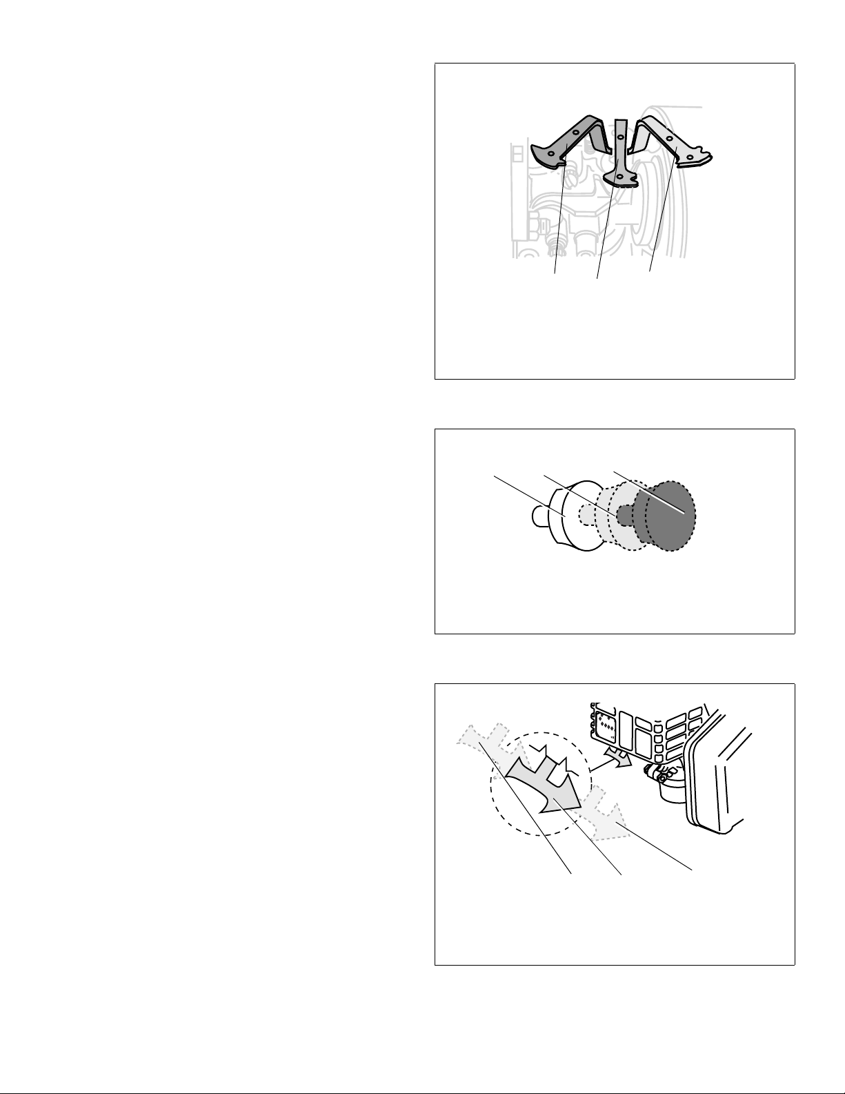
NOTES
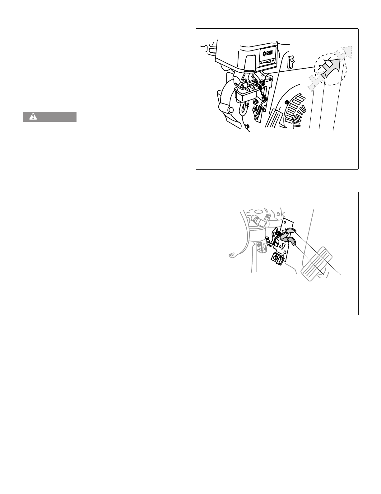
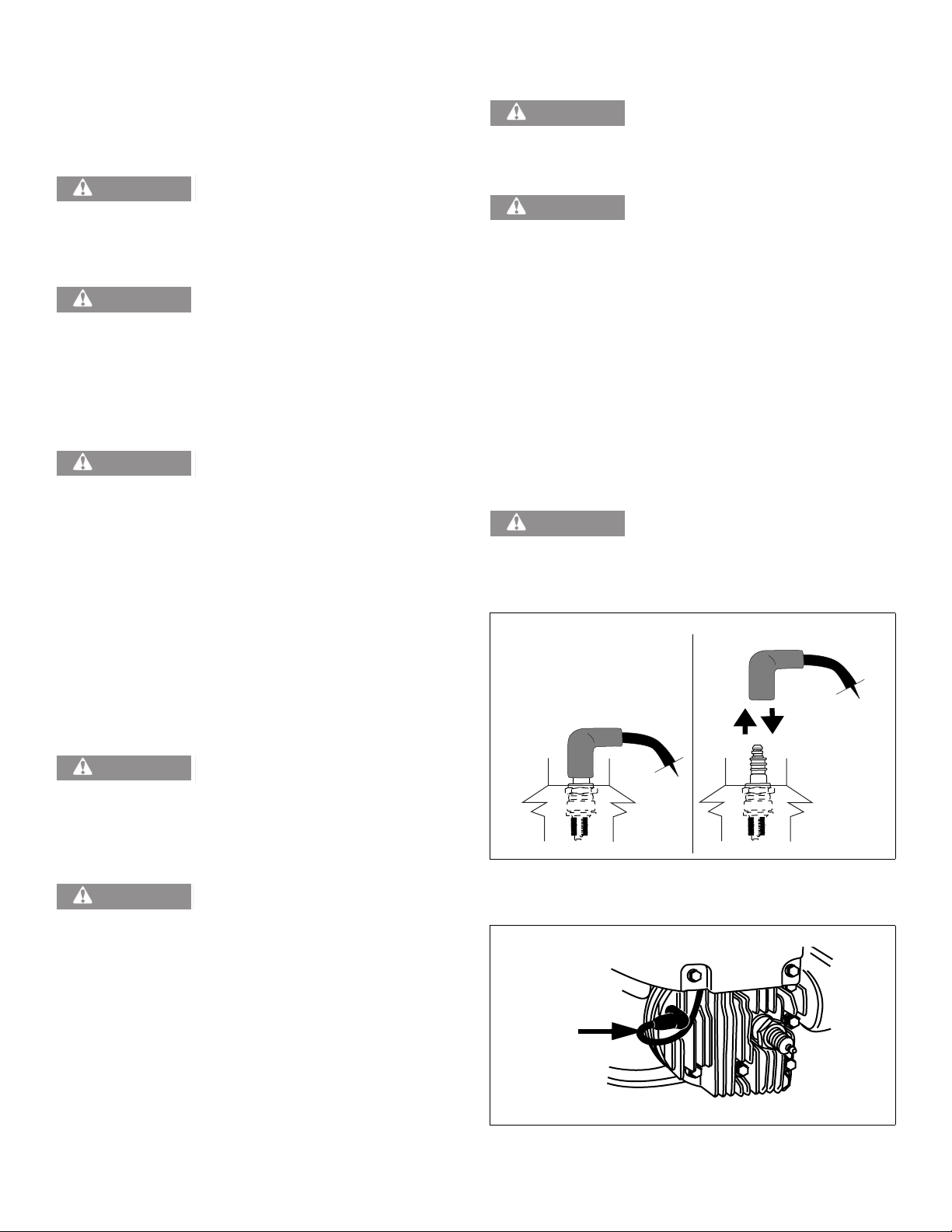
Some engines are equipped with a horizontal mounted
choke control. See Figure 23.
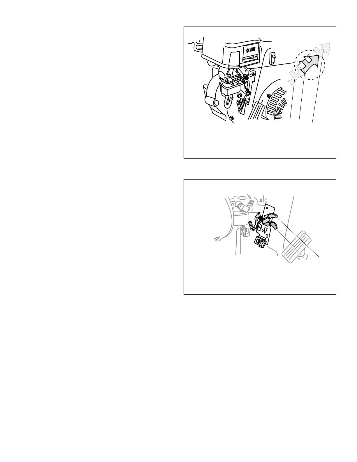
Some engines are equipped with a Remote Choke Control.
See Figure 24.
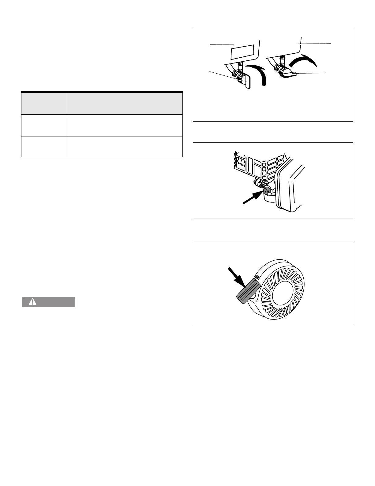
Some OH195EA/OH195EP engines are equipped with a
choke control lever under the muffler. See Figure 25.
3
1. No Choke Position
2. 1/2 Choke Position
3. Full Choke Position
Figure 23. Horizontal Mount Choke Control Positions
2
1
21 3
1. No Choke Position
2. 1/2 Choke Position
3. Full Choke Position
Figure 24. Remote Choke Control Positions
21 3
1. No Choke Position
2. 1/2 Choke Position
3. Full Choke Position
Figure 25. OH195EA/OH195EP Choke Control
Positions
181-1269-14 Power Sport Recreational Application Operator’s Manual Page 13
Page 16
NOTES
Climate Guard
RUN
C
H
OKE
!
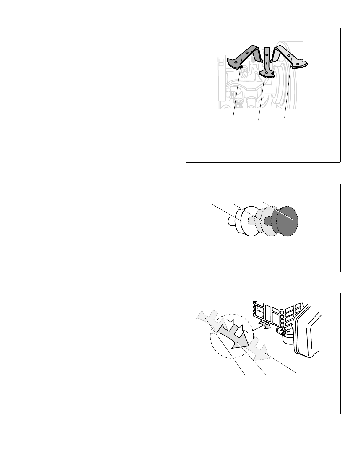
OH318EA engines are equipped with a choke control lever
located under the air cleaner. See Figure 26.
If restarting a warm engine move Choke Control to “NO
CHOKE” position. See Figure 26.
Power Sport engines are equipped with a standard Spring
Loaded Throttle Control to ensure the throttle will return to
engine idle speed when it is released or if the cable fails.
The throttle control must be in the idle position when starting
engine. See Figure 27.
4. Push starter button or turn ignition switch key to start engine.
NOTE
DO NOT operate an electric starter for more than 5 seconds
each attempt.
5. When engine starts:
a. Release starter button or ignition switch key.
b. Momentarily move Choke Lever to “1/2 CHOKE”
position until engine runs smoothly.
c. Next, move Choke Lever to “NO CHOKE” position.
2
1 3
1. No Choke Position
2. 1/2 Choke Position
3. Full Choke Position
Figure 26. OH318EA Choke Control Positions
NOTES
If engine starts but falters when Choke Lever is moved to
“NO CHOKE” position:
a. Momentarily move Choke Lever back to “FULL
CHOKE” position.
b. Next, move Choke Lever to “1/2 CHOKE” position
until engine runs smoothly.
c. Finally, move Choke Lever to “NO CHOKE” position.
6. If engine dies after Choke Lever is moved to “NO CHOKE” position, repeat steps 2 thru 5 to restart engine.
7. If engine fires, but does not continue to run, move Choke Lever to “NO CHOKE” position and start engine.
8. If engine fails after 3 attempts in the “NO CHOKE” position, repeat steps 2 thru 7 to restart engine.
9. If engine does not start after following steps 1 thru 8, contact your Authorized Tecumseh Servicing Dealer. DO NOT attempt to start or troubleshoot this engine in any other way.
1. High Speed Position
2. Idle Range
Figure 27. Engine Speed Control Positions
2
1
Page 14 Power Sport Recreational Application Operator’s Manual 181-1269-14
Page 17
B. Engines with Recoil Starters
I. Engine With Primer Bulb
Only one of the following two sections will apply to your
engine. See Table 6.
Table 6. Engines with Recoil Starters
If your
engine has:
Primer Bulb
Only
Choke Only "II. Engine With Choke" instructions on
1. To avoid carbon monoxide poisoning, be sure engine is outdoors in a well-ventilated area.
2. Be sure fuel valve is open, if provided. See Figure 28.
3. When starting a cold engine, push primer bulb firmly with your thumb 3 times, allowing primer bulb to return completely to original position between pushes. See Figure 29.
LH318EA (HM80-90), LH358EA (HM100) and OH318EA
Models DO NOT have a primer bulb.
Cooler temperatures may require pushing primer bulb firmly
with your thumb 5 times.
DO NOT use primer to restart a warm engine after a short
shutdown. Doing so will flood the engine and may result in
equipment malfunction.
"I. Engine With Primer Bulb" instructions.
page 16.
NOTES
Go to:
3
1
1. Fuel Valve in “OPEN” Position Shown
2. Fuel Valve in “OFF” Position Shown
3. Fuel Tank
Figure 28. Optional Fuel Valve
Figure 29. OH195EA/OH195EP Engine Primer Bulb
.
3
2
WARNING
engine causing serious injury. To avoid this risk, carefully
follow these instructions:
4. Grasp starter cord handle. See Figure 30.
a. Pull rope out slowly until you feel drag.
b. Next, pull rope with one rapid full arm stroke.
c. Return rope slowly to original position.
Following the instructions listed in the steps above avoids
potential damage to the recoil mechanism.
5. If engine fails to start after 3 attempts, repeat steps 2 thru 4.
6. If engine does not start after following steps 1 thru 5, contact your Authorized Tecumseh Servicing Dealer. DO NOT attempt to start or troubleshoot this engine in any other way.
181-1269-14 Power Sport Recreational Application Operator’s Manual Page 15
When pulling starter rope, the rope
can unexpectedly jerk back toward
Figure 30. Starter Cord Handle
NOTE
Page 18
II. Engine With Choke
1. To avoid carbon monoxide poisoning, be sure engine is
outdoors in a well-ventilated area.
2. Be sure fuel valve is open, if provided. See Figure 28
on page 15.
3. Move Choke Control to “FULL CHOKE” position.
NOTES
Some engines are equipped with a horizontal mounted
choke control. See Figure 31.
Some engines are equipped with a Remote Choke Control.
See Figure 32.
Some OH195EA/OH195EP engines are equipped with a
choke control lever located under the muffler. See Figure
33.
3
1. No Choke Position
2. 1/2 Choke Position
3. Full Choke Position
Figure 31. Horizontal Mount Choke Control Positions
2
1
21 3
1. No Choke Position
2. 1/2 Choke Position
3. Full Choke Position
Figure 32. Remote Choke Control Positions
21 3
1. No Choke Position
2. 1/2 Choke Position
3. Full Choke Position
Figure 33. OH195EA/OH195EP Choke Control
Positions
Page 16 Power Sport Recreational Application Operator’s Manual 181-1269-14
Page 19
NOTES
Climate Guard
RUN
C
H
OKE
!
OH318EA engines are equipped with a choke control lever
located under the air cleaner. See Figure 34.
If restarting a warm engine move Choke Control to “NO
CHOKE” position. See Figure 31 thru 34.
Power Sport engines are equipped with a standard Spring
Loaded Throttle Control to ensure the throttle will return to
engine idle speed when it is released or if the cable fails.
The throttle control must be in the idle position when starting
engine. See Figure 35.
WARNING
When pulling starter rope, the rope
can unexpectedly jerk back toward
engine causing serious injury. To avoid this risk, carefully
follow these instructions:
4. Grasp starter cord handle. See Figure 30 on page 15.
a. Pull rope out slowly until you feel drag.
b. Next, pull rope with one rapid full arm stroke.
c. Return rope slowly to original position.
NOTE
Following the instructions in the steps above will also help
avoid potential damage to the recoil mechanism.
5. When engine starts:
a. Momentarily move Choke Lever to “1/2 CHOKE”
position until engine runs smoothly.
b. Next, move Choke Lever to “NO CHOKE” position.
NOTES
If engine starts but falters when Choke Lever is moved to
“NO CHOKE” position:
a. Momentarily move Choke Lever back to “FULL
CHOKE” position.
b. Next, move Choke Lever to “1/2 CHOKE” position
until engine runs smoothly.
c. Finally, move Choke Lever to “NO CHOKE” position.
6. If engine dies after Choke Lever is moved to “NO
CHOKE” position, repeat steps 2 thru 5 to restart
engine.
2
1 3
1. No Choke Position
2. 1/2 Choke Position
3. Full Choke Position
Figure 34. OH318EA Choke Control Positions
2
1. High Speed Position
2. Idle Range
Figure 35. Engine Speed Control Positions
1
7. If engine fires, but does not continue to run, move
Choke Lever to ’NO CHOKE” position and start engine.
8. If engine fails after 3 attempts in the “NO CHOKE” posi-
tion, repeat steps 2 thru 7 to restart engine.
9. If engine does not start after following steps 1 thru 8,
contact your Authorized Tecumseh Servicing Dealer.
DO NOT attempt to start or troubleshoot this engine in
any other way.
181-1269-14 Power Sport Recreational Application Operator’s Manual Page 17
Page 20
VI. Stopping Your Engine and
WARNING
WARNING
WARNING
Short-Term Storage
Stop engine according to equipment manufacturer’s
instructions.
WARNING
children, NEVER leave the engine unattended when it is
running. Always turn off the engine before exiting the vehicle
and remove ignition key, if provided.
To avoid unsupervised operation of a
recreational vehicle, especially by
VIII. Maintenance
An adult should perform maintenance
on this engine. Only allow children to
perform maintenance if an adult has determined they are
experienced and capable of such operation.
To prevent accidental starting when
working on equipment, always:
• Disconnect spark plug wire and keep it away from
spark plug. See Figure 36.
WARNING
potential sources of ignition such as hot water and space
heaters, clothes dryers, electric motors, etc.
NEVER store the engine with fuel in
the fuel tank inside a building with
VII. Transporting Your Recreational
Vehicle
WARNING
space if there is any gasoline in the tank. Fuel vapor or
spilled fuel may ignite.
If there is fuel in the fuel tank, close the fuel shut off valve, if
equipped, and transport the recreational vehicle in an open
vehicle, such as an open trailer or open bed of a pickup
truck.
If you do not have an open vehicle and have to transport the
recreational vehicle in a closed vehicle, follow these steps
for emptying the fuel tank before transporting:
1. Empty fuel tank by using a commercially available suction device designed for use with gasoline.
NEVER transport this vehicle inside
another vehicle or in any enclosed
• Keep the disconnected spark plug wire
securely away from metal parts where arcing
could occur.
• Attach the spark plug wire to the grounding
post, if provided. See Figure 37.
• Disconnect battery at negative terminal first, if
engine is equipped with an electric starter.
• Turn off all engine switches.
• Remove ignition key, if provided.
The muffler and other engine parts
become extremely hot during
operation and remain hot after the engine has stopped. To
avoid severe burns on contact, stay away from these areas.
WARNING
2. Drain fuel into an approved red GASOLINE container, being careful to avoid spilling.
3. Run the engine until remaining fuel is consumed.
WARNING
engine in enclosed areas.
Page 18 Power Sport Recreational Application Operator’s Manual 181-1269-14
DO NOT pour fuel from engine or
siphon fuel by mouth.
Figure 36. Disconnecting/Connecting Spark Plug
NEVER leave the engine unattended
when it is running and NEVER run
Figure 37. Spark Plug Grounding Post
Page 21
A. Checking and Changing Oil
To avoid engine damage, it is important to:
• Check oil level before each use and every 5
operating hours when engine is warm.
• Change oil after first 2 operating hours and every 3
months or every 25 operating hours thereafter;
more often if operated in extremely dusty or dirty
conditions. Engine should still be warm but not hot
from recent use.
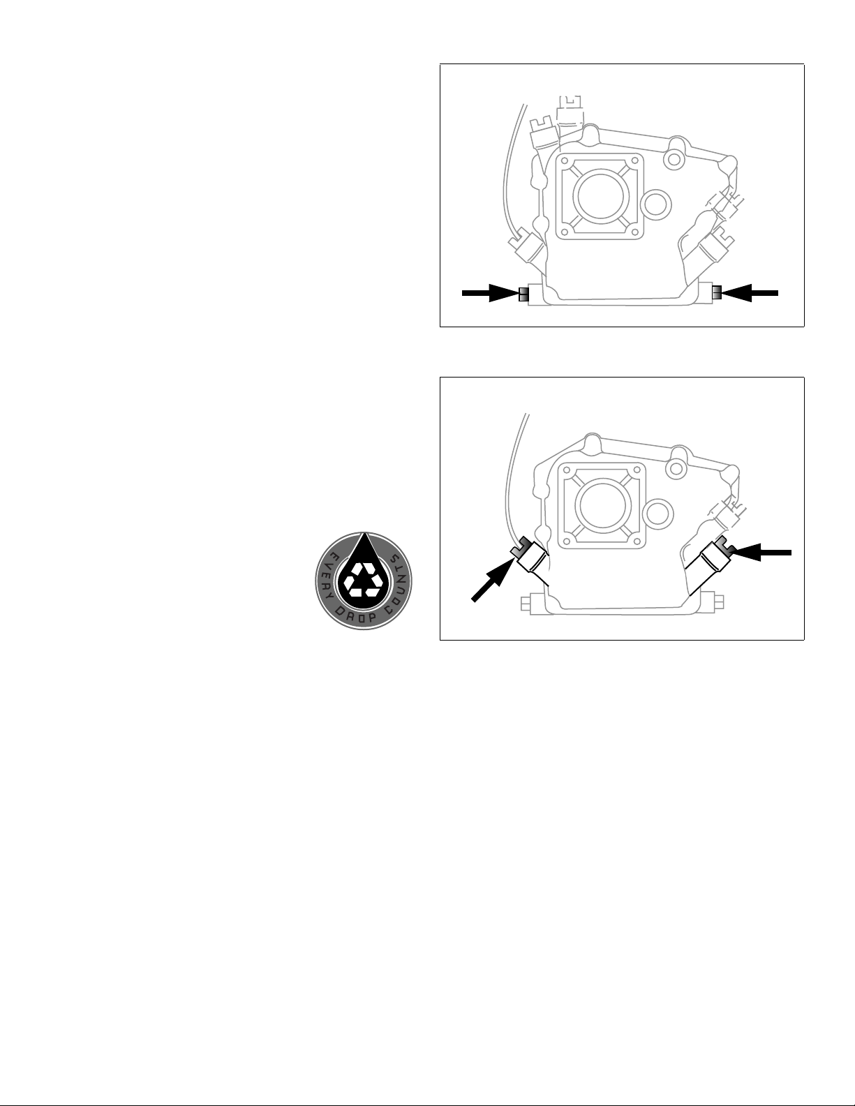
1. Be sure you find the correct drain plug location, if provided. See Figure 38.
2. Disconnect spark plug wire and keep it away from
spark plug. See "G. Avoid Accidental Starts" instructions on page 3. See Figure 36.
• Keep the disconnected spark plug wire securely
away from metal parts where arcing could occur.
• Attach the spark plug wire to the grounding post, if
provided. See Figure 37.
3. Be sure the gas cap is on and is tightened securely.
4. Clean area around oil drain plug.
Figure 38. Possible Oil Drain Plug Location(s)
5. Place approved recyclable oil container under oil drain plug, tipping engine to position the oil drain plug at the lowest point on the engine.
6. Remove oil drain plug and drain oil. See Figure 38.
NOTE
Used oil must be disposed of at a proper
collection center.
7. Install oil drain plug and tighten securely.
8. Fill with recommended oil. See "III. Oil and Fuel Specifications" instructions on page 5. See Table 1 and see
Table 2 on page 5. See Figure 39.
9. Wipe away any spilled oil.
10. Carefully disconnect spark plug wire from grounding post, if provided. See Figure 37.
11. Carefully re-connect spark plug wire to spark plug. See Figure 36.
Figure 39. Possible Oil Fill Plug Location(s)
181-1269-14 Power Sport Recreational Application Operator’s Manual Page 19
Page 22
B. Removing Debris From Engine
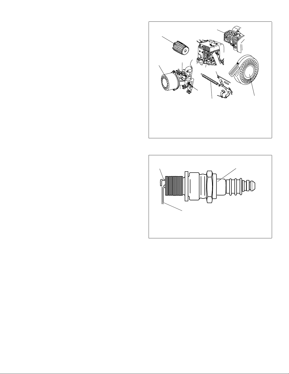
Before each use, remove grass clippings, dirt, debris, snow
or ice from the following areas:
• Cooling fins
• Air intake screens
5
3
• Levers
• Linkage
• Guards
Removing debris will facilitate adequate cooling, correct
engine speed or reduce the risk of fire. See Figure 40.
C. Spark Plug
Check spark plug yearly or every 100 operating hours.
1. Clean area around spark plug.
2. Remove and inspect spark plug.
3. Replace spark plug if porcelain is cracked or if electrodes are:
• Pitted
• Burned
• Fouled with deposits
4. Check electrode gap with wire feeler gauge and set gap to .030 in. (0.76mm) if necessary. See Figure 41.
5. Install spark plug and tighten securely.
NOTE
A resistor spark plug must be used for replacement. Contact
your Authorized Tecumseh Servicing Dealer for a
Tecumseh Resistor Spark Plug.
3
1. Levers and Linkage
2. Cooling Fins
3. Air Cleaner Cover
4. Flywheel Guard
5. Muffler Guard
2
1
1
Figure 40. Debris Removal Areas
1
2
1
3
4
1. .030 in. (0.76mm) Gap
2. Electrodes
3. Porcelain
Figure 41. Resistor Spark Plug
Page 20 Power Sport Recreational Application Operator’s Manual 181-1269-14
Page 23
D. Cleaning/Replacing Air Cleaner
Your engine has an air cleaner which helps prevent
premature engine wear and failure. NEVER run engine
without complete air cleaner installed on engine. Your air
cleaner’s filter(s) periodically needs to be cleaned or
replaced. To do this, you first need to determine the type of
air cleaner on your engine. Your engine will be equipped
with one of the following air cleaners; Type A, B, C, D or E.
See Figure 42 thru Figure 46. Follow instructions for the air
cleaner type that resembles your model.
NOTE
Contact your Authorized Tecumseh Servicing Dealer for
Tecumseh Air Cleaners.
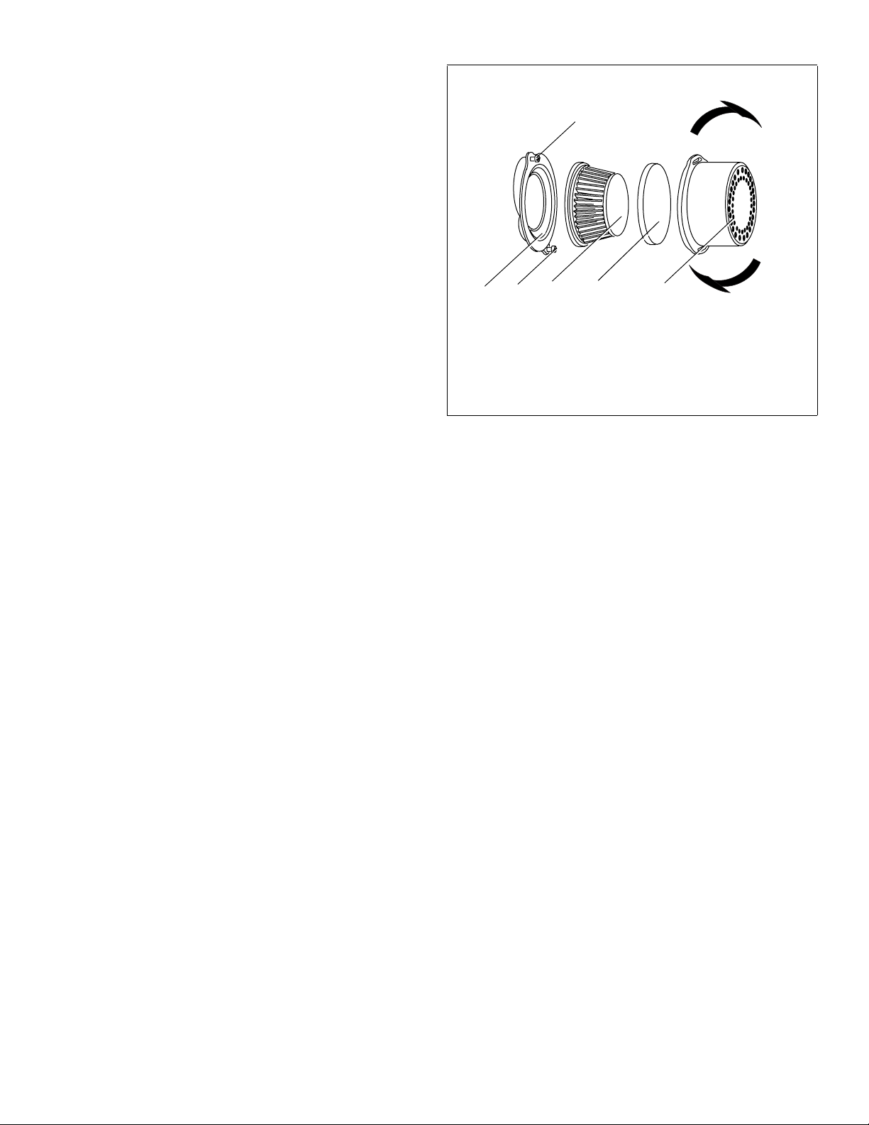
2
45132
I. Servicing Foam Pre-Filters
Clean foam pre-filter every 3 months or every 25 operating
hours. Clean daily if used in extremely dusty conditions.
After removing the pre-filter, follow these cleaning
instructions below:
1. Wash in warm water and detergent solution then press (DO NOT twist) until all dirt is removed.
2. Rinse thoroughly until water is clear.
3. Wrap in a clean cloth and press (DO NOT twist) until completely dry.
NOTE
DO NOT oil a foam pre-filter.
4. Replace foam pre-filter onto paper filter.
II. Servicing Paper Filters
Paper filters cannot be cleaned and must be replaced once
a year or every 100 operating hours; more often if used in
extremely dusty conditions. Replacement filters are
available at an Authorized Tecumseh Servicing Dealer.
Follow the instructions next to the drawing of your air
cleaner to remove and replace it.
NOTE
DO NOT put oil on or clean a paper filter.
1. Base
2. Cover Screws
3. Paper Filter
4. Foam Pre-Filter (Optional)
5. Cover
Figure 42. Type “A” Air Cleaner Assembly
E. Type “A” Air Cleaner
1. Loosen cover screws. See Figure 42.
2. Turn cover counterclockwise and remove from base.
3. Remove optional foam pre-filter, if provided, from cover. Inspect for dirt or debris accumulation. If either is present see "I. Servicing Foam Pre-Filters" instructions.
4. Remove paper filter from base. Inspect filters for discoloration or dirt accumulation. If either is present, see "II. Servicing Paper Filters" instructions.
5. Clean inside of base and cover thoroughly.
6. Install new paper element into base.
7. Install optional foam pre-filter into cover.
8. Turn cover clockwise and attach to base.
9. Tighten screws securely.
181-1269-14 Power Sport Recreational Application Operator’s Manual Page 21
Page 24
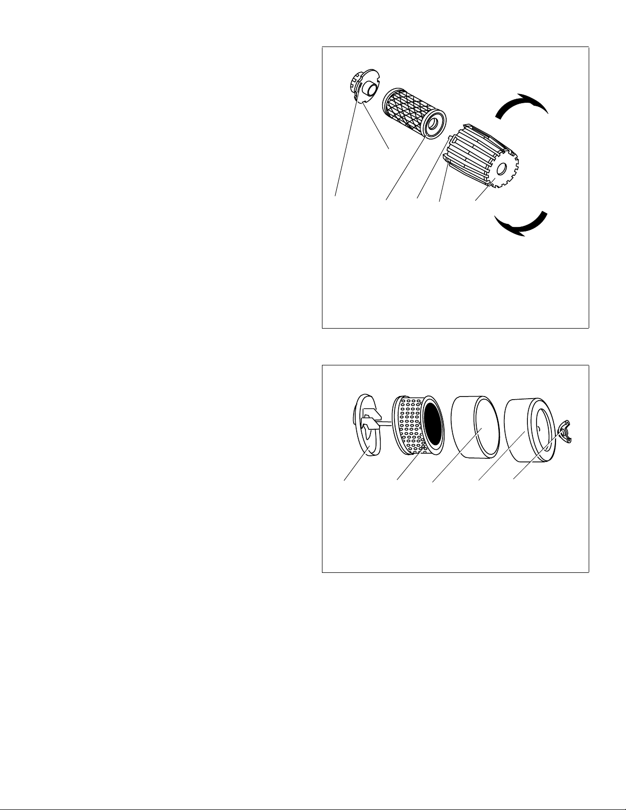
F. Type “B” Air Cleaner
1. Turn cover to left (counterclockwise) and remove it and paper filter from base. See Figure 43.
2. Discard filter.
3. Clean cover and base thoroughly.
4. Install new paper filter into cover.
5. Position clean cover and filter against base with tab on cover inserted into lower left corner of slot in base.
6. Push cover firmly against base and turn to right (clock wise) as far as it will go.
3
7. Be sure retainers are locked around base.
G. Type “C” Air Cleaner
1. Remove wing nut. See Figure 44.
2. Remove cover and clean thoroughly.
3. Remove foam pre-filter, if provided, from outside of paper filter. Inspect for dirt or debris accumulation. If either is present see "I. Servicing Foam Pre-Filters" instructions on page 21.
4. Remove paper filter element from base. Inspect filters for discoloration or dirt accumulation. If either is present, see "II. Servicing Paper Filters" instructions on page 21.
5. Clean inside of base and cover thoroughly.
6. Install clean paper filter element onto base.
7. Install clean foam pre-filter, if provided, over paper element.
8. Install clean cover over filters.
9. Install wing nut and tighten securely.
5624
1
1. Retainer
2. Slot
3. Base
4. Paper Filter
5. Tab
6. Cover
Figure 43. Type “B” Air Cleaner Assembly
5
34
21
1. Wing Nut
2. Cover
3. Foam Pre-Filter (Optional)
4. Paper Filter
5. Base
Figure 44. Type “C” Air Cleaner Assembly
Page 22 Power Sport Recreational Application Operator’s Manual 181-1269-14
Page 25
H. Climate Guard® Anti-Icing Air Cleaners
Some engines may be equipped with a Climate Guard antiicing air cleaner that prevents ice from forming in the
carburetor when the engine is run at temperatures below
°°
32 F (0 C).
Engines equipped with the baffle will have an opening
which draws warm air from the muffler into the air cleaner
housing. To work effectively, it is necessary for the Cold
Weather Baffle to block cold air from entering the air
cleaner.
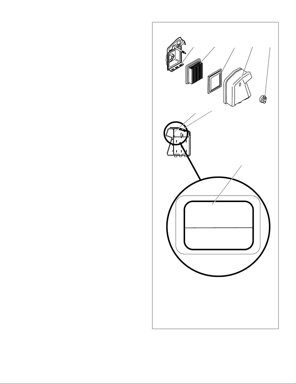
I. Type “D” Air Cleaner
78465
1. Remove wing nut and cover. See Figure 45.
2. Remove foam pre-filter, if provided, from cover. Inspect for dirt or debris accumulation. If either is present see "I. Servicing Foam Pre-Filters" instructions on page 21.
3. Remove paper element from base. Inspect for dirt or
debris accumulation. If either is present see "II. Servicing Paper Filters" instructions on page 21.
4. Clean inside of base and cover thoroughly.
5. Install clean paper element into base.
6. Install clean foam pre-filter, if provided, into cover.
7. Install cover on base.
8. Install wing nut and tighten securely.
A. At temperatures of 32 F (0 C) and Below
°°
1. Remove wing nut from air cleaner cover. See Figure 45.
2. Remove air cleaner cover from base.
3. Remove red baffle from inside of air cleaner cover.
4. Insert red baffle in “WINTER” position shown.
5. Install air cleaner cover onto base.
23
COLD WEATHER
BAFFLE
Position “S” for Summer
°
Above 32 F (0 C)
Position “W” for Winter
Below 32 F (0 C)
°
°
°
1
6. Install wing nut and tighten securely.
B. At temperatures above 32 F (0 C)
1. Remove wing nut from air cleaner cover. See Figure 45.
2. Remove air cleaner cover from base.
3. Remove red baffle from inside of air cleaner cover.
4. Insert red baffle in “SUMMER” position shown.
5. Install air cleaner cover onto base.
°°
1. Red Baffle
2. Baffle Summer Position
3. Baffle Winter Position
4. Base
5. Paper Element
6. Foam Pre-Filter (Optional)
7. Cover
8. Wing Nut
6. Install wing nut and tighten securely.
Figure 45. Type “D” Climate Guard Air Cleaner
Assembly
181-1269-14 Power Sport Recreational Application Operator’s Manual Page 23
Page 26
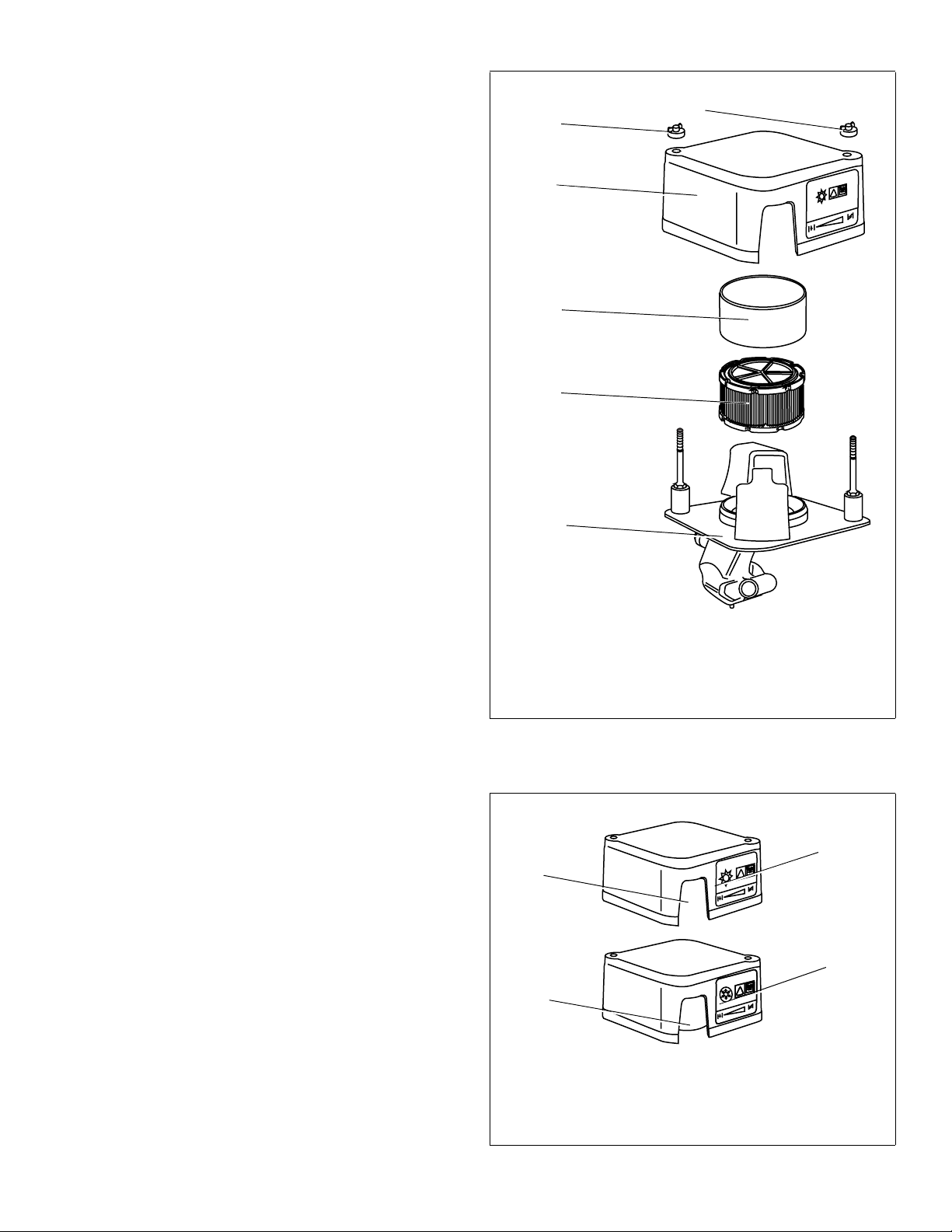
II. Type “E” Air Cleaner
!
!
!!
1. Remove wing nuts and air cleaner cover.
2. Remove foam pre-filter from paper filter, if provided, and inspect for dirt or debris accumulation. If either is present see "I. Servicing Foam Pre-Filters" instructions on page 21.
3. Remove paper filter from base and inspect for dirt or
debris accumulation. If either is present see "II. Servicing Paper Filters" instructions on page 21.
4. Clean inside of base and air cleaner cover thoroughly.
5. Install paper filter into base.
6. Install foam filter onto paper filter.
7. Install air cleaner cover on base.
8. Install wing nuts and tighten securely.
A. At temperatures of 32 F (0 C) and Below
°°
1. Remove wing nuts from air cleaner cover. See Figure 46.
2. Remove air cleaner cover from base.
3. Rotate air cleaner cover in “WINTER” position shown. See Figure 47.
1
1
2
Climate Gu
ard
3
4
5
4. Install air cleaner cover onto base.
NOTE
Be sure air cleaner cover is in correct “WINTER” position
with snowflake symbol visible.
5. Install wing nuts and tighten securely.
B. At temperatures above 32 F (0 C)
°°
1. Remove wing nuts from air cleaner cover. See Figure 46.
2. Remove air cleaner cover from base.
3. Rotate air cleaner cover in “SUMMER” position shown. See Figure 47.
4. Install air cleaner cover onto base.
NOTE
Be sure air cleaner cover is in correct “SUMMER” position
with sun symbol visible.
5. Install wing nuts and tighten securely.
I. Alternator (Optional)
For alternator related electrical problems such as:
• Inoperative starter
• Discharged battery
• Fuse replacement
• Alternator maintenance/repairs
See your equipment manufacturer’s instructions and an
Authorized Tecumseh Servicing Dealer.
1. Wing Nuts
2. Air Cleaner Cover
3. Foam Pre-Filter (Optional)
4. Paper Filter
5. Base
Figure 46. Type “E” Climate Guard Air Cleaner
Assembly
1
3
1. Summer Position—above 32 F (0 C)
2. Sun Symbol
3. Winter Position—below 32 F (0 C)
°°
°°
4. Snowflake Symbol
Figure 47. Air Cleaner Cover Positions
2
4
Page 24 Power Sport Recreational Application Operator’s Manual 181-1269-14
Page 27

J. Adjustments
WARNING
IX. Storing Your Engine
Do not make any engine adjustments. Factory settings are
satisfactory for most conditions. If adjustments are needed,
contact your Authorized Tecumseh Servicing Dealer.
K. Carburetor
If you think your carburetor needs adjusting, see your
nearest Authorized Tecumseh Servicing Dealer. Engine
performance should not be affected at altitudes up to 7,000
feet (2,134 meters). For operation at higher elevations,
contact your Authorized Tecumseh Servicing Dealer.
L. Engine Speed
WARNING
Tampering with the governor setting can lead to a runaway
vehicle and cause the engine to operate at unsafe speeds.
NEVER tamper with factory setting of engine governor.
Running the engine faster than the speed set at the factory
can be dangerous and will VOID THE ENGINE
WARRANTY.
To avoid serious injury or death, do
not modify engine in any way.
A. Short Term/Seasonal Storage
I. Clean Engine
Before servicing the engine remove the blower housing. In
addition, remove grass clippings, dirt and debris from the
following areas:
• Cooling fins
• Air intake screen
• Levers
• Linkage
•Guards
• Carburetor
•Head
Removing debris will facilitate adequate cooling, correct
engine speed and reduce the risk of fire.
II. Fuel Storage
NEVER store engine with fuel in fuel
tank inside a building with potential
sources of ignition such as hot water and space heaters,
clothes dryers, electric motors, etc. Failure to do so may
result in an explosion and result in death or serious injury.
NOTE
If engine fuel stored in the gas tank and/or an approved gas
container is to be unused without gasoline stabilizer for
more than 15-30 days, prepare it for short term/seasonal
storage. See "IV. Fuel Treatment" instructions on page 26.
If engine fuel is to be stored for more than one season,
without gasoline stabilizer, it will gradually deteriorate. Also,
if it is stored in the engine’s gas tank without gasoline
stabilizer it is likely that your carburetor will have gum
deposits, a clogged fuel system and will void your warranty.
Prepare the fuel for extended storage. See "B. Extended
Storage" instructions on page 26.
If you operate the engine during all 4 seasons, it is not
necessary to lubricate the cylinder bore.
181-1269-14 Power Sport Recreational Application Operator’s Manual Page 25
Page 28

III. Fuel System
WARNING
WARNING
To avoid stale gas and carburetor problems, treat the fuel
system in the following method below:
NOTE
Tecumseh recommends using ULTRA-FRESH™ or Fuel
Saver Plus Gasoline Stabilizer plus Fuel System Cleaner as
an acceptable method of minimizing formation of fuel gum
deposits during storage. This product is available from your
Authorized Tecumseh Servicing Dealer.
Always follow mix ratio found on stabilizer container. Failure
to do so may result in equipment damage.
It is not necessary to drain stabilized gas from carburetor.
IV. Fuel Treatment
1. Add fuel stabilizer according to manufacturer’s instructions.
2. Run engine at least 10 minutes after adding stabilizer to allow it to reach carburetor.
WARNING
potential sources of ignition such as hot water and space
heaters, clothes dryers, electric motors, etc.
Instead of using a fuel preservative/stabilizer, you can
empty the fuel tank as described under "I. Draining Fuel"
instructions. See "B. Extended Storage" instructions.
NEVER store the engine with fuel in
the fuel tank inside a building with
NOTE
B. Extended Storage
I. Draining Fuel
NOTES
Clean debris from engine before draining fuel from
carburetor. See "I. Clean Engine" instructions on page 25.
If you have prepared your fuel for short term storage it is not
necessary to drain fuel that contains stabilizer from your
carburetor. See "A. Short Term/Seasonal Storage"
instructions on page 25.
To avoid severe injury or death,
DO NOT pour fuel from engine or
siphon fuel by mouth.
1. To prevent serious injury from fuel fires, empty fuel tank by running engine until it stops from lack of fuel. DO NOT attempt to pour fuel from engine.
2. Run the engine while waiting until the remaining fuel is consumed.
NEVER leave the engine unattended
when it is running and NEVER run
engine in enclosed areas.
3. Begin servicing the cylinder bore. See "II. Oil Cylinder Bore" instructions on page 27.
Page 26 Power Sport Recreational Application Operator’s Manual 181-1269-14
Page 29

II. Oil Cylinder Bore
III. Battery
WARNING
prevent serious injury from fuel fires, follow these
instructions:
1. Disconnect spark plug wire and keep it away from spark plug. See Figure 36.
• Keep the disconnected spark plug wire
securely away from metal parts where arcing
could occur.
• Attach the spark plug wire to the grounding
post, if provided. See Figure 37.
• Disconnect battery at negative terminal first, if
engine is equipped with an electric starter.
• Turn off all engine switches.
• Remove ignition key, if provided.
1. Remove spark plug.
2. Squirt 1oz. (30ml) of clean engine oil into spark plug
hole.
3. Cover spark plug hole with rag to prevent fuel from
spraying from spark plug hole when starter rope is
pulled.
For engines equipped with recoil starters proceed to Step 5.
For engines equipped with electric starters proceed to
Step 6.
4. Grasp starter cord handle and pull out slowly using a
full arm stroke. Repeat once. (This will distribute oil
throughout the cylinder to prevent corrosion during
storage.)
5. Install spark plug.
6. Carefully disconnect spark plug wire from grounding
post, if provided.
7. Connect spark plug wire before attempting to start
engine.
When lubricating cylinder bore, fuel
may spray from spark plug hole. To
NOTES
See equipment manufacturer’s instructions for proper
battery storage, if provided.
IV. Clean Engine
Remove any grass clippings, dirt, debris, snow, ice or slush
from exterior of engine.
X. Preventing Forest, Brush and Grass
Fires
Local, state and federal laws may require use of a spark
arrester to prevent fires. For example, it is a violation of
California Public Resources Code (section 4442) to use or
operate engine on any forest-covered, brush-covered or
unimproved grass-covered land unless engine is equipped
with a spark arrester. Spark arrester must be maintained in
effective working order by owner and/or operator.
To determine if your engine has a spark arrester, locate the
muffler on your engine. For example, the muffler discharge
will have a spark arrester cover that reads “Tecumseh
Screen Type 36085”.
If your engine does not have a spark arrester, you may
purchase one from your Authorized Tecumseh Servicing
Dealer. In some cases the muffler may need to be replaced
to allow the spark arrester to be installed.
181-1269-14 Power Sport Recreational Application Operator’s Manual Page 27
Page 30

XI. Maintenance Intervals
Maintenance is one of the most important things that you
can do to extend the life of your Tecumseh Engine. If you
are unable to perform maintenance intervals yourself,
contact your nearest Authorized Tecumseh Servicing
Dealer. You may also call Tecumseh Power Company at
1-800-558-5402 or visit www.TecumsehPower.com to
locate your dealer.
ALWAYS promptly follow maintenance intervals listed on
the next two pages and see Table 7.
Table 7. Maintenance Intervals
Procedure Time
Change Oil
Check Oil Level
Clean Cooling Fins
Change Oil
Clean Foam
Pre-Filter
Replace Paper
Element
Check Spark Plug
Replace Spark Plug
First Scheduled Maintenance
After First 2 Hours When Engine is Warm
1. Change Oil
Date_______________Owner/Dealer
Before Each Use Scheduled Maintenance
Every 5 Hours or Before Each Use
1. Check Oil Level
2. Clean Cooling Fins
Date_______________Owner/Dealer
Date_______________Owner/Dealer
Date_______________Owner/Dealer
Date_______________Owner/Dealer
Date_______________Owner/Dealer
Date_______________Owner/Dealer
Date_______________Owner/Dealer
After first 2 hrs.
when engine is warm
5 hrs. or Before Each Use
5 hrs. or Before Each Use
25 hrs. or 3 mos.
25 hrs. or 3 mos.
100 hrs. or
seasonally
100 hrs. or
seasonally
200 hrs. or
seasonally
Every 25 Hours or 3 Months Scheduled Maintenance
1. Change Oil
2. Clean Foam Pre-Filter
Date_______________Owner/Dealer
Date_______________Owner/Dealer
Date_______________Owner/Dealer
Date_______________Owner/Dealer
Date_______________Owner/Dealer
Date_______________Owner/Dealer
Date_______________Owner/Dealer
Date_______________Owner/Dealer
Date_______________Owner/Dealer
Date_______________Owner/Dealer
Date_______________Owner/Dealer
Date_______________Owner/Dealer
Date_______________Owner/Dealer
Date_______________Owner/Dealer
Date_______________Owner/Dealer
Date_______________Owner/Dealer
Date_______________Owner/Dealer
Date_______________Owner/Dealer
Date_______________Owner/Dealer
Date_______________Owner/Dealer
Date_______________Owner/Dealer
Date_______________Owner/Dealer
Date_______________Owner/Dealer
Date_______________Owner/Dealer
Date_______________Owner/Dealer
Date_______________Owner/Dealer
Date_______________Owner/Dealer
Date_______________Owner/Dealer
Date_______________Owner/Dealer
Date_______________Owner/Dealer
Date_______________Owner/Dealer
Date_______________Owner/Dealer
Date_______________Owner/Dealer
Date_______________Owner/Dealer
Date_______________Owner/Dealer
Date_______________Owner/Dealer
Date_______________Owner/Dealer
Date_______________Owner/Dealer
Date_______________Owner/Dealer
Date_______________Owner/Dealer
Date_______________Owner/Dealer
Page 28 Power Sport Recreational Application Operator’s Manual 181-1269-14
Page 31

Every 100 Hours or Seasonally
1. Replace Paper Element
2. Check Spark Plug
Date_______________Owner/Dealer
Date_______________Owner/Dealer
Date_______________Owner/Dealer
Date_______________Owner/Dealer
Date_______________Owner/Dealer
Date_______________Owner/Dealer
Date_______________Owner/Dealer
Date_______________Owner/Dealer
Date_______________Owner/Dealer
Date_______________Owner/Dealer
Date_______________Owner/Dealer
Date_______________Owner/Dealer
Date_______________Owner/Dealer
Date_______________Owner/Dealer
Date_______________Owner/Dealer
Date_______________Owner/Dealer
Date_______________Owner/Dealer
Date_______________Owner/Dealer
Date_______________Owner/Dealer
Date_______________Owner/Dealer
Date_______________Owner/Dealer
Date_______________Owner/Dealer
Date_______________Owner/Dealer
Date_______________Owner/Dealer
Date_______________Owner/Dealer
Date_______________Owner/Dealer
Date_______________Owner/Dealer
Date_______________Owner/Dealer
Date_______________Owner/Dealer
Date_______________Owner/Dealer
Date_______________Owner/Dealer
Date_______________Owner/Dealer
Date_______________Owner/Dealer
Date_______________Owner/Dealer
Date_______________Owner/Dealer
Date_______________Owner/Dealer
Date_______________Owner/Dealer
Date_______________Owner/Dealer
Date_______________Owner/Dealer
Date_______________Owner/Dealer
Date_______________Owner/Dealer
Date_______________Owner/Dealer
Every 200 Hours or Seasonally
1. Replace Spark Plug
Date_______________Owner/Dealer
Date_______________Owner/Dealer
Date_______________Owner/Dealer
Date_______________Owner/Dealer
Date_______________Owner/Dealer
Date_______________Owner/Dealer
Date_______________Owner/Dealer
Date_______________Owner/Dealer
Date_______________Owner/Dealer
Date_______________Owner/Dealer
Date_______________Owner/Dealer
Date_______________Owner/Dealer
Date_______________Owner/Dealer
Date_______________Owner/Dealer
Date_______________Owner/Dealer
Date_______________Owner/Dealer
Date_______________Owner/Dealer
Date_______________Owner/Dealer
Date_______________Owner/Dealer
Date_______________Owner/Dealer
Date_______________Owner/Dealer
Date_______________Owner/Dealer
Date_______________Owner/Dealer
Date_______________Owner/Dealer
Date_______________Owner/Dealer
Date_______________Owner/Dealer
Date_______________Owner/Dealer
Date_______________Owner/Dealer
Date_______________Owner/Dealer
Date_______________Owner/Dealer
Date_______________Owner/Dealer
Date_______________Owner/Dealer
Date_______________Owner/Dealer
Date_______________Owner/Dealer
Date_______________Owner/Dealer
Date_______________Owner/Dealer
Date_______________Owner/Dealer
Date_______________Owner/Dealer
Date_______________Owner/Dealer
Date_______________Owner/Dealer
Date_______________Owner/Dealer
Date_______________Owner/Dealer
Date_______________Owner/Dealer
181-1269-14 Power Sport Recreational Application Operator’s Manual Page 29
Page 32

Page 30 Power Sport Recreational Application Operator’s Manual 181-1269-14
Page 33

NOTES
181-1269-14 Power Sport Recreational Application Operator’s Manual Page 31
Page 34

Page 32 Power Sport Recreational Application Operator’s Manual 181-1269-14
Page 35

NOTES
181-1269-14 Power Sport Recreational Application Operator’s Manual Page 33
Page 36

Page 34 Power Sport Recreational Application Operator’s Manual 181-1269-14
Page 37

NOTES
181-1269-14 Power Sport Recreational Application Operator’s Manual Page 35
Page 38

CALIFORNIA & US EPA EMISSION CONTROL WARRANTY STATEMENT
The U. S. Environmental Protection Agency (“EPA”), the
California Air Resources Board (“CARB”) and Tecumseh Power
Company are pleased to explain the Federal and California
Emission Control Systems Warranty on your new small off-road
engine. In California, new 1995 and later small off-road engines
must be designed, built and equipped to meet the State’s
stringent anti-smog standards. In other states, new 1997 and later
model year engines must be designed, built and equipped, at the
time of sale, to meet the U.S. EPA regulations for small non-road
engines. Tecumseh Power Company will warrant the emission
control system on your small off-road engine for the periods of
time listed below, provided there has been no abuse, neglect,
unapproved modification, or improper maintenance of your small
off-road engine.
Your emission control system may include parts such as the
carburetor, air cleaner assembly, ignition system, exhaust system,
crankcase breather assembly and, the evaporative control
system. Also included may be the compression release system
and other emission-related assemblies.
Where a warrantable condition exists, Tecumseh Power
Company will repair your small off-road engine at no cost to you
for diagnosis, parts and labor.
MANUFACTURER’S EMISSION CONTROL
SYSTEM WARRANTY COVERAGE
Emission control systems on 1995 and later model year California
small off-road engines are warranted for two years as hereinafter
noted. In other states, 1997 and later model year engines are also
warranted for two years. If, during such warranty period, any
emission-related part on your engine is defective in materials or
workmanship, the part will be repaired or replaced by Tecumseh
Power Company
OWNER’S WARRANTY RESPONSIBILITIES
As the small off-road engine owner, you are responsible for the
performance of the required maintenance listed in your Operator’s
Manual, but Tecumseh Power Company will not deny warranty
solely due to the lack of receipts or for your failure to provide
written evidence of the performance of all scheduled
maintenance.
As the small off-road engine owner, you should, however, be
aware that Tecumseh Power Company may deny you warranty
coverage if your small off-road engine or a part thereof has failed
due to abuse, neglect, improper maintenance or unapproved
modifications.
You are responsible for presenting your small off-road engine to a
Tecumseh Authorized Service Outlet (any Tecumseh Registered
Service Dealer, Tecumseh Authorized Service Distributor or
Tecumseh Central Warehouse Distributor) as soon as a problem
exists. The warranty repairs should be completed in a reasonable
amount of time, not to exceed 30 days.
Warranty service can be arranged by contacting either an
Authorized Tecumseh Servicing Dealer and/or Tecumseh Power
Company, c/o Service Manager, 900 North Street, Grafton, WI
53024-1499. Telephone 1-262-377-2700 [or in USA/Canada call
1-800-558-5402].
IMPORTANT NOTE
This warranty statement explains your rights and obligations
under the Emission Control System Warranty (“ECS Warranty”)
which is provided to you by Tecumseh Power Company pursuant
to California law. Tecumseh Power Company also provides to
original purchasers of new Tecumseh Power Company engines
the Tecumseh Power Company Limited Warranties for New
Tecumseh Engines and Electronic Ignition Modules. The
Tecumseh Power Company Limited Warranties for New
Tecumseh Engines and Electronic Ignition Modules (“Tecumseh
Power Company Warranty”) are located on the back cover of the
Operator’s Manual, enclosed with all new Tecumseh Power
Company engines. The ECS Warranty applies only to the
emission control system of your new engine. To the extent that
there is any conflict in terms between the ECS Warranty and the
Tecumseh Power Company Warranty, the ECS Warranty shall
apply except in any circumstances in which the Tecumseh Power
Company Warranty may provide a longer warranty period. Both
the ECS Warranty and the Tecumseh Power Company Warranty
describe important rights and obligations with respect to your new
engine.
Warranty service can only be performed by a Tecumseh Power
Company Authorized Servicing Dealer. At the time of requesting
warranty service, evidence must be presented of the date of sale
to the original purchaser. The purchaser shall pay any charges for
making service calls and/or for transporting the products to and
from the place where the inspection and/or warranty work is
performed. The purchaser shall be responsible for any damage or
loss incurred in connection with the transportation of any engine
or any part(s) thereof submitted for inspection and/or warranty
work.
If you have any questions regarding your warranty rights and
responsibilities, you should contact Tecumseh Power Company at
1-262-377-2700 or in USA/Canada call 1-800-558-5402.
Revised July, 2005
IMPORTANT!
The emission Regulations may be different for your country. The emissions Control Warranty Statement is only applicable
to engines with an emissions compliance statement and decal that references “Emissions Regulations”.
Page 36 Power Sport Recreational Application Operator’s Manual 181-1269-14
Page 39

EMISSION CONTROL SYSTEM WARRANTY
Emission Control System Warranty (“ECS Warranty”) for 1995
and later model year California small off-road engines (for other
states, 1997 and later model year engines):
A. APPLICABILITY: This warranty shall apply to 1995 and later
model year California small off-road engines (for other states,
1997 and later model year engines). The ECS Warranty
Period shall begin on the date the new engine or equipment is
delivered to its original, end-use purchaser, and shall continue
for 24 consecutive months thereafter.
B. GENERAL EMISSIONS WARRANTY COVERAGE:
Tecumseh Power Company warrants to the original, end-use
purchaser of the new engine or equipment and to each
subsequent purchaser that each of its small off-road engines
is:
1. Designed, built and equipped so as to conform with all
applicable regulations adopted by the Air Resources
Board pursuant to its authority in Chapters 1 and 2, Part 5,
Division 26 of the Health and Safety Code, and
2. Free from defects in materials and workmanship which, at
any time during the ECS Warranty Period, will cause a
warranted emissions-related part to fail to be identical in all
material respects to the part as described in the engine
manufacturer’s application for certification.
C. THE ECS WARRANTY ONLY PERTAINS TO EMISSION-
RELATED PARTS ON YOUR ENGINE AS FOLLOWS:
1. Any warranted, emissions-related parts which are not
scheduled for replacement as required maintenance in the
Operator’s Manual shall be warranted for the ECS
Warranty Period. If any such part fails during the ECS
Warranty Period, it shall be repaired or replaced by
Tecumseh Power Company according to Subsection 4
below. Any such part repaired or replaced under the ECS
Warranty shall be warranted for any remainder of the ECS
Warranty Period.
2. Any warranted, emissions-related part which is scheduled
only for regular inspection as specified in the Operator’s
Manual shall be warranted for the ECS Warranty Period. A
statement in such written instructions to the effect of
“repair or replace as necessary”, shall not reduce the ECS
Warranty Period. Any such part repaired or replaced under
the ECS Warranty shall be warranted for the remainder of
the ECS Warranty Period.
3. Any warranted, emissions-related part which is scheduled
for replacement as required maintenance in the Operator’s
Manual, shall be warranted for the period of time prior to
the first scheduled replacement point for that part. If the
part fails prior to the first scheduled replacement, the part
shall be repaired or replaced by Tecumseh Power
Company according to Subsection 4 below. Any such
emissions-related part repaired or replaced under the ECS
Warranty, shall be warranted for the remainder of the ECS
Warranty Period prior to the first scheduled replacement
point for such emissions-related part.
4. Repair or replacement of any warranted, emissionsrelated part under this ECS Warranty shall be performed
at no charge to the owner at a Tecumseh Authorized
Service Outlet.
5. The owner shall not be charged for diagnostic labor which
leads to the determination that a part covered by the ECS
Warranty is in fact defective, provided that such diagnostic
work is performed at a Tecumseh Authorized Service
Outlet.
6. Tecumseh Power Company shall be liable for damages to
other original engine components or approved
modifications proximately caused by a failure under
warranty of an emission-related part covered by the ECS
Warranty.
7. Throughout the ECS Warranty Period, Tecumseh Power
Company shall maintain a supply of warranted emissionrelated parts sufficient to meet the expected demand for
such emission-related parts.
8. Any Tecumseh Power Company authorized and approved
emission-related replacement part may be used in the
performance of any ECS Warranty maintenance or repair
and will be provided without charge to the owner. Such
use shall not reduce Tecumseh Power Company ECS
Warranty obligations.
9. Unapproved add-on or modified parts may not be used to
modify or repair a Tecumseh Power Company engine.
Such use voids this ECS Warranty and shall be sufficient
grounds for disallowing an ECS Warranty claim.
Tecumseh Power Company shall not be liable hereunder
for failures of any warranted parts of a Tecumseh Power
Company engine caused by the use of such an
unapproved add-on or modified part.
EMISSION-RELATED PARTS INCLUDE THE FOLLOWING:
1. Carburetor Assembly including internal components:
a) Carburetor gaskets
b) Intake pipe
2. Air Cleaner Assembly including components:
a) Air filter element
3. Ignition System including components:
a) Spark plug
b) Ignition module
c) Flywheel assembly
4. Exhaust System including components:
a) Catalytic muffler (if so equipped)
b) Muffler gasket (if so equipped)
c) Exhaust manifold (if so equipped)
5. Crankcase Breather Assembly including components
a) Breather connection tube
6. Evaporative Control System including components:
a) Fuel line(s)
b) Fuel filter
c) Canister (if so equipped)
d) Fuel tank (if so equipped)
e) Fuel fill cap (if so equipped)
Revised July, 2005
IMPORTANT!
The emission Regulations may be different for your country. The emissions Control Warranty Statement is only applicable
to engines with an emissions compliance statement and decal that references “Emissions Regulations”.
181-1269-14 Power Sport Recreational Application Operator’s Manual Page 37
Page 40
XII. Warranty Information
Warranty requirements for engines sold outside of the USA may vary from country to
country. For warranty details for your specific country, contact your national
Tecumseh Service Distributor. If help is needed in locating your national service
distributor, you may contact Tecumseh c/o International Service Coordinator, 900
North Street, Grafton, Wisconsin USA 53024-1499. Telephone is 1-262-377-2700 or
in USA/Canada call 1-800-558-5402.
Limited Warranty for New Tecumseh Engines
and Electronic Ignition Modules
For the time period shown below from the date of purchase, Tecumseh Power
Company will, at its option as the exclusive remedy, either repair or replace for the
original purchaser, free of charge, any part of any new Tecumseh engine which is
found, upon examination by any Authorized Tecumseh Servicing Dealer to be
DEFECTIVE IN MATERIAL AND/OR WORKMANSHIP, except as provided below.
This Limited Warranty DOES NOT COVER (i) any Tecumseh engine or part(s)
thereof used to power any vehicle in competitive racing and/or used on any
commercial or rental track, or (ii) defects or damage caused by alterations or
modifications of new Tecumseh engines or parts or by normal wear, accidents,
improper maintenance, improper use or abuse of the product, or failure to follow the
instructions contained in an Instruction Manual for the operation of the new
Tecumseh engine or part. The cost of normal maintenance or replacement of service
items which are not defective shall be paid for by the original purchaser. At the time
warranty service is requested, evidence must be presented of the date of purchase
by the original purchaser. Any charge for making service calls and/or for transporting
any engine or part(s) thereof to and from the place where the inspection and/or
warranty work is performed is payable solely by the purchaser. The purchaser is
responsible for any damage or loss incurred in connection with the transportation of
any engine or part(s) thereof submitted for inspection and/or warranty work.
Warranty service can only be performed by an Authorized Tecumseh Servicing
DEALER. Warranty service can be arranged by contacting either a Tecumseh
Authorized Service Outlet (any Tecumseh Registered Service Dealer, Tecumseh
Master Service Dealer, Tecumseh Authorized Service Distributor, or Tecumseh
Central Warehouse Distributor) or by contacting Tecumseh c/o Service Manager,
900 North Street, Grafton, Wisconsin 53024-1499.
ENGINE WARRANTY PERIOD
Consumer Use+
WARRANTY CATEGORY~ WITHIN USA & CANADA OUTSIDE USA & C ANADA
(A) 90 day 90 day
(B) 1 year 1 year
(C) 2 years 1 year
(D) 2 years 2 years**
(E) 2 years 2 years
(H) 2 ‘n 10* 2 ‘n 10*
(K) 2 ‘n 10* 2 ‘n 10*
Commercial Use++
WARRANTY CATEGORY~ WITHIN USA & CANADA OUTSIDE USA & C ANADA
(A) No Warranty No Warranty
(B) 1 year 1 year
(C) 1 year 1 year
(D) 1 year 1 year
(E) 1 year 1 year
(H) 1 year 1 year
(K) 2 ‘n 10* 1 year
* 2 years on engine, 10 years (the first 5 years covering parts and labor only; the
second 5 years covering parts only) on electronic ignition.
** 1 year for Australian/New Zealand for rotary mower engines.
+ For purposes of this warranty policy, ìconsumer useî shall mean consumer’s
personal, resi dential, household use by the original retail purchaser.
++ For purposes of this warranty policy, “commercial use”shall mean all other
uses, including use for commercial, income producing, or rental purposes.
~ The engine warranty category of your engine can be determined by review of
the engine model number on the “Important Engine Information” decal. One
letter in the engine model number will be preceded by the word WARRANTY:
and surrounded by parens (A), (B), (C), (D), (E), (H) or (K) and that letter is your
engine warranty category designation. IN CALIFORNIA ONLY, THIS EXPRESS
WARRANTY IS SUPPLEMENTED BY THE TECUMSEH CALIFORNIA
EMISSION CONTROL WARRANTY STATEMENT.
THIS EXPRESS WARRANTY IS IN LIEU OF ALL OTHER EXPRESS WARRANTIES. Neither Tecumseh nor any of its affiliates makes any warranties, representations, or
promises, written or oral, as to the quality of the engine or any of its parts, other than as set forth herein. ANY IMPLIED WARRANTY OF MARKETABILITY OR FITNESS FOR
A PARTICULAR PURPOSE, TO THE EXTENT THAT EITHER MAY APPLY TO ANY TECUMSEH ENGINE OR PART(S) THEREOF, SHALL BE LIMITED IN DURATION
TO THE PERIODS OF THE EXPRESS WARRANTIES SHOWN IN THE WARRANTY PERIOD CHART ABOVE AND TO THE EXTENT PERMITTED BY LAW AND ANY
AND ALL IMPLIED WARRANTIES ARE EXCLUDED. IN NO EVENT WILL TECUMSEH BE LIABLE FOR ANY INCIDENTAL, CONSEQUENTIAL OR SPECIAL
DAMAGES AND/OR EXPENSES. Some states do not allow limitations on how long an implied warranty lasts or the exclusion or limitation of incidental or consequential
damages, so the above limitation(s) or exclusion(s) may not apply to you. This Limited Warranty gives you specific legal rights and you may also have other legal rights which
vary from state-to-state.
!
WARNING
Revised January, 2004
CALIFORNIA PROPOSITION 65
The engine exhaust from this product contains chemicals known
to the State of California to cause cancer, birth defects or other
reproductive harm.
TecumsehPower
Tecumseh Power Company • Grafton, Wisconsin 53024-1499 •USA
Telephone: 1-800-558-5402
Visit us at: www.TecumsehPower.com
181-1269-14
(English) 1/01/08
 Loading...