

Tecumseh CDU4542EXG-S, CDUS4538EXCS-S, CDU4524EGF-S, CDUS4524EGE-S, CDU4538EGF-S Installation Instructions Manual
...Page 1
Outdoor Condensing Units
www.Tecumseh.com
INSTALLATION
INSTRUCTION
MANUAL
Page 2
2
TABLE OF CONTENT
03
ODCU NOMENCLATURE, ODCU EXPLODED VIEW AND SCOPE OF SUPPLY
4-6
DIMENSIONS OF THE UNIT AND INSTALLATION INSTRUCTIONS
06
UNPACKING, LIFTING & HANDLING INSTRUCTIONS
ODCU MOUNTING OPTIONS
07
ODCU SERIAL/TECH SPEC. LABEL LOCATION
08
ELECTRICALS AND WIRING DIAGRAMS
9-10
CONNECTIONS OF SUCTION & LIQUID LINE AND REFRIGERANT PIPING.
11
PRESSURE CONTROLS (MINI PRESSURE SWITCHES)
11
SYSTEM FLUSHING, PURGING, AND PRESSURE TESTING FOR LEAKS
12- 13
SYSTEM EVACUATION AND SYSTEM CHARGING
14
15
APPROVED HERMETIC COMPRESSOR OILS
SYSTEM START-UP PROCEDURE
15
16
OPERATIONAL CHECKOUT PROCEDURE
MAINTENANCE (ODCU) AND TROUBLE SHOOTING
16-17
A, COMPRESSOR NOT STARTING – NOT HUMMING.
18
B, COMPRESSOR NOT STARTING HUMS BUT TRIPS ON THERMAL
PROTECTOR
18
C. COMPRESSOR STARTS AND RUNS, BUT SHORT CYCLES ON
THERMAL PROTECTOR
18
D. UNIT RUNS OK BUT RUN CYCLE IS SHORTER THAN NORMAL
(DUE TO HP/LP CUT OUT SWITCHES)
19
16-17
REFRIGERATION ACCESSORIES AND OPERATIONAL CHECKOUT
PROCEDURE
19-20
INSTRUCTIONS FOR THE SIGHT GLASS SOLDER TYPE AND
STACKING OF THE UNIT
21- 23
Page 3
C D U
OUTDOOR TYPE
CONDENSING UNIT
S- SINGLE PHASE
NO LETTER- THREE
PHASE
APPLICATION
2 - LOW BACK
4 - HIGH BACK
CAPACITY
NO. OF DIGITS IN
COOLING CAPACITY
REFRIGERANT
E- R22
Z- R4040A
ACCESSORIES
S- STANDARD
FB- FULLY BUILT
CAPACITY
FIRST TWO DIGITS IN
COOLING CAPACITY
38000 BTU/HR @ 60 HZ
VOLTAGE
CODES
XG, XC, GH,...
S XXXXE
38
5
4
3
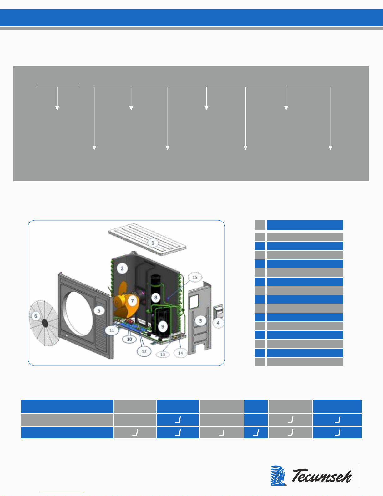
ODCU NOMENCLATURE
ODCU EXPLODED VIEW
ODCU PARTS LIST
CONDENSER COIL
RIGHT PANEL
ELECL. COVER/LIFT HANDLE
FRONT PANEL
FAN GRILL
FAN MOTER WITH BLADER
RECEIVER
COMPRESSOR
FILTER DRIER
SIGHT GLASS
SOLENOID VALVE
SUCTION SERVICE VALVE
LIQUID SERVICE VALVE
HP / LP SWITCH
TOP PANEL
1
2
3
4
5
6
7
8
9
10
11
12
13
14
15
SCOPE OF SUPPLY
CDUS XXXX X XXX-S ( STANDARD)
CDUS XXXX X XXX-FB ( FULLY BUILT)
TYPES OF MODELS RECEIVER FILTER DRIER SIGHT GLASS LLSV HP/LP SWITCH SERVICE VALVES
RECEIVER
S.N.
Page 4
4
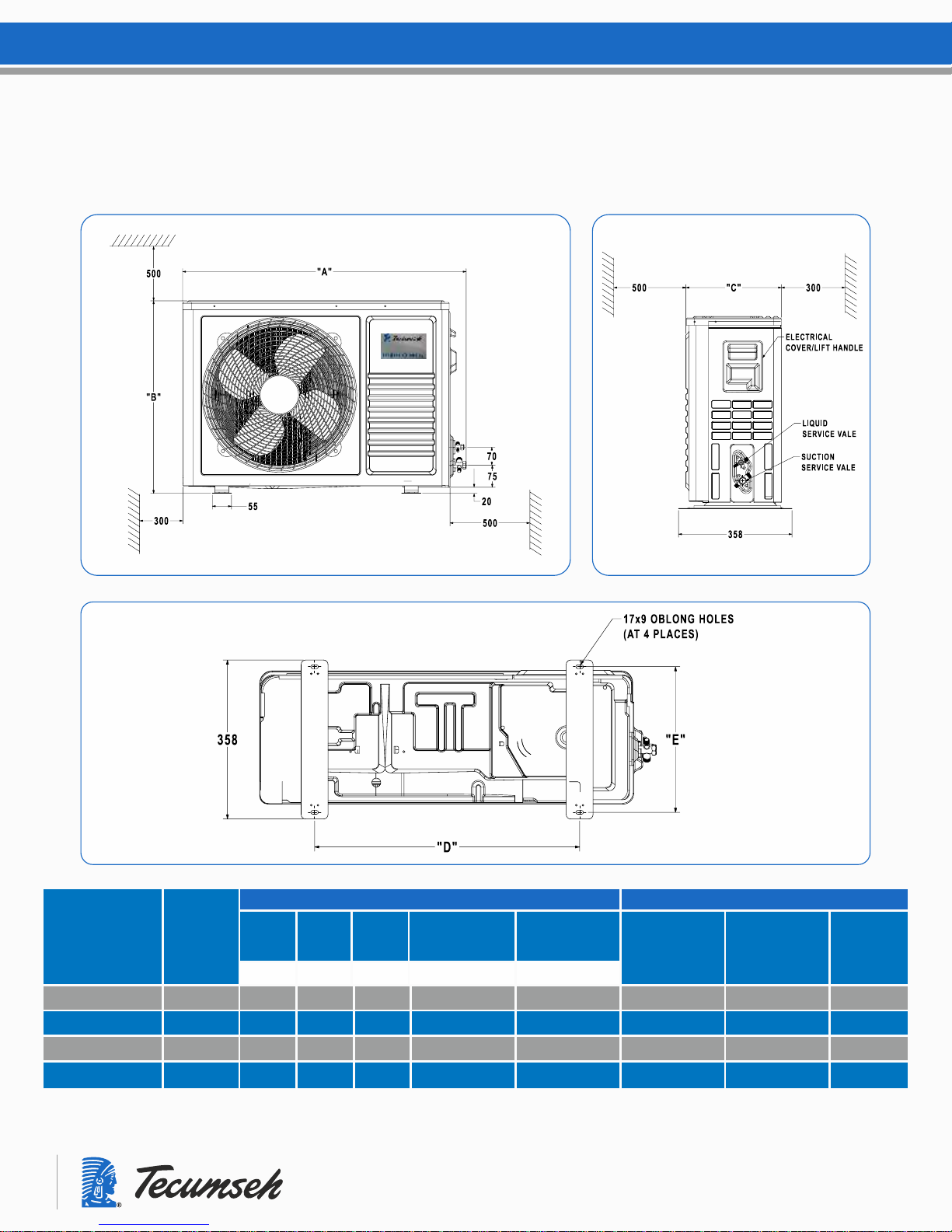
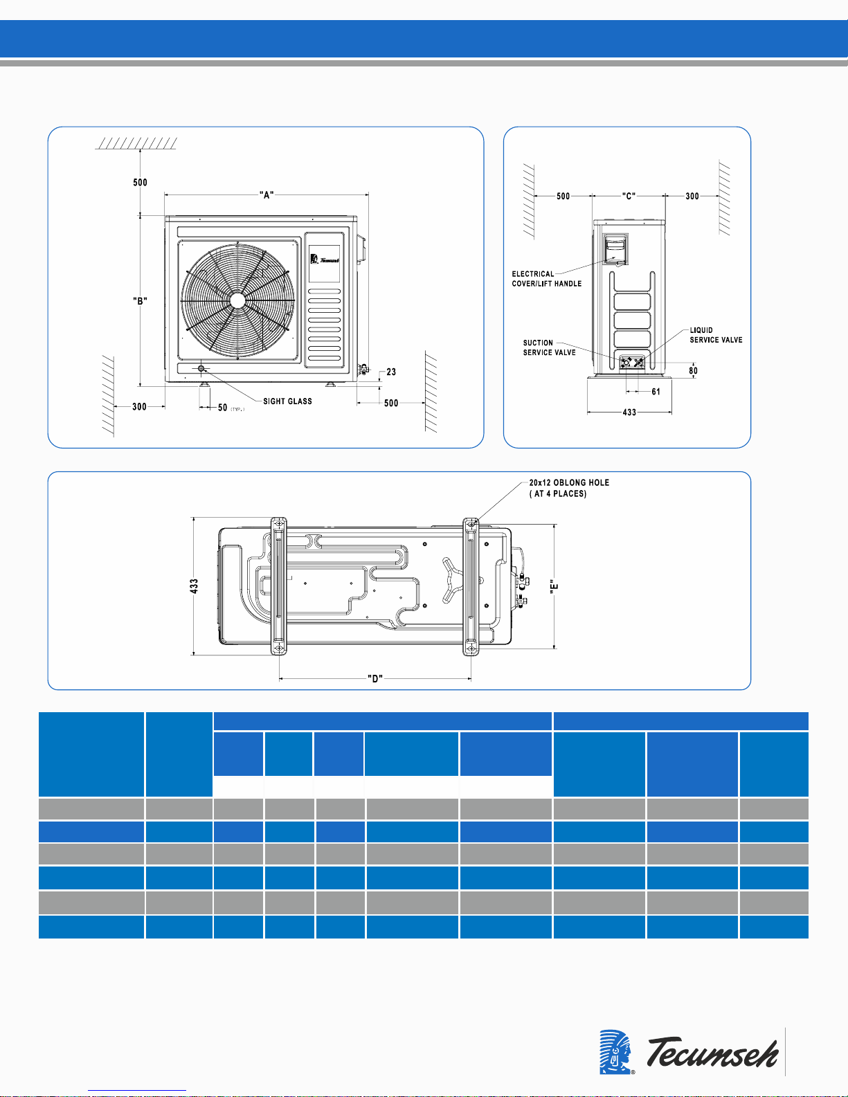
DIAGRAM - 1
DIAGRAM
LENGTH HEIGHT WIDTH
HORIZONTAL
MOUNTING
PITCH
SUCTION LINE
FLARE NUT
TYPE
WEIGHT
KGS
1
670 607 300 520
1/2"
53
1
670 607 300 520
1/2"
53
1
1
670 607 300 520
5/8"
53
670 607 300 520
5/8"
53
"A" "B" "C" "D"
DIMENSIONS ARE IN MM
DIMENSIONS & MINIMUM WALL
CLEARANCES SUGGESTED FOR INSTALLATION
UNIT MODEL
CDUS4524EGE-S
CDU4532EGF-S
CD454532EGH-S
CDU4524EGF-S
LIQUID LINE
FLARE
NUT TYPE
1/4"
1/4"
3/8"
3/8"
UPTO VERTICAL
MOUNTING
PITCH
328
328
328
328
"E”
Page 5
5
DIAGRAM
LENGTH HEIGHT WIDTH
HORIZONTAL
MOUNTING
PITCH
SUCTION LINE
FLARE NUT
TYPE
WEIGHT
KGS
"A" "B" "C" "D"
DIMENSIONS ARE IN MM
UNIT MODEL
CDUS4538EXCS-S
CDU4538EGF-S
CDU4542EXG-FB
CDU4542EXG-S
LIQUID LINE
FLARE
NUT TYPE
UPTO VERTICAL
MOUNTING
PITCH
"E”
DIAGRAM - 2
2
975 810 400 675 395
5/8" 3/8"
68
2
975 810 400 675 395
*5/8" 3/8"
75
2
975 810 400 675 395
5/8" 3/8"
68
2
975 810 400 675 395
5/8" 3/8"
68
CDUS4538EXC-FB
2
975 810 400 675 395
*5/8" 3/8"
75
CDU4538EGF-FB
2
975 810 400 675 395
*5/8" 3/8"
75
* ADAPTOR NUT 3/4 TO 5/8
Page 6
6
INSTALLATION INSTRUCTIONS
TO PROPERLY LOCATE THESE OUTDOOR CONDENSING UNITS, CAREFULLY
CONSIDER THESE IMPORTANT FACTORS:
UNPACKING, LIFTING/HANDLING INSTRUCTION
Weight Of The Unit. If units are installed on the roof, their weight and weight
distribution should be checked against the building specifications and the building
codes.
Distance Of The Unit to the refrigerated cabinet and power supply socket.
Space Around The Unit and in between adjacent units. This should consider
prevention of the re-circulation of the air and ensure enough airflow through the unit.
(Refer Drg.1 in page no. 4)
These distances should also provide enough room around the units so that
enclosure panels may be removed and that adequate accessibility is provided to the
compressor, electrical boxes and other controls for maintenance.
Orientation of the units should consider the prevailing wind direction. It is
recommended not to position the units in such a way that the airflow direction
through the unit faces to prevailing wind direction for the area. The units should be
mounted securely on adequate rigid and leveled bases, to avoid improper
lubrication conditions for the compressor. Never use the shipment pallet as a
permanent mounting base. If vibrations is a concern, then proper vibration insulators
should be installed under the mounting base.
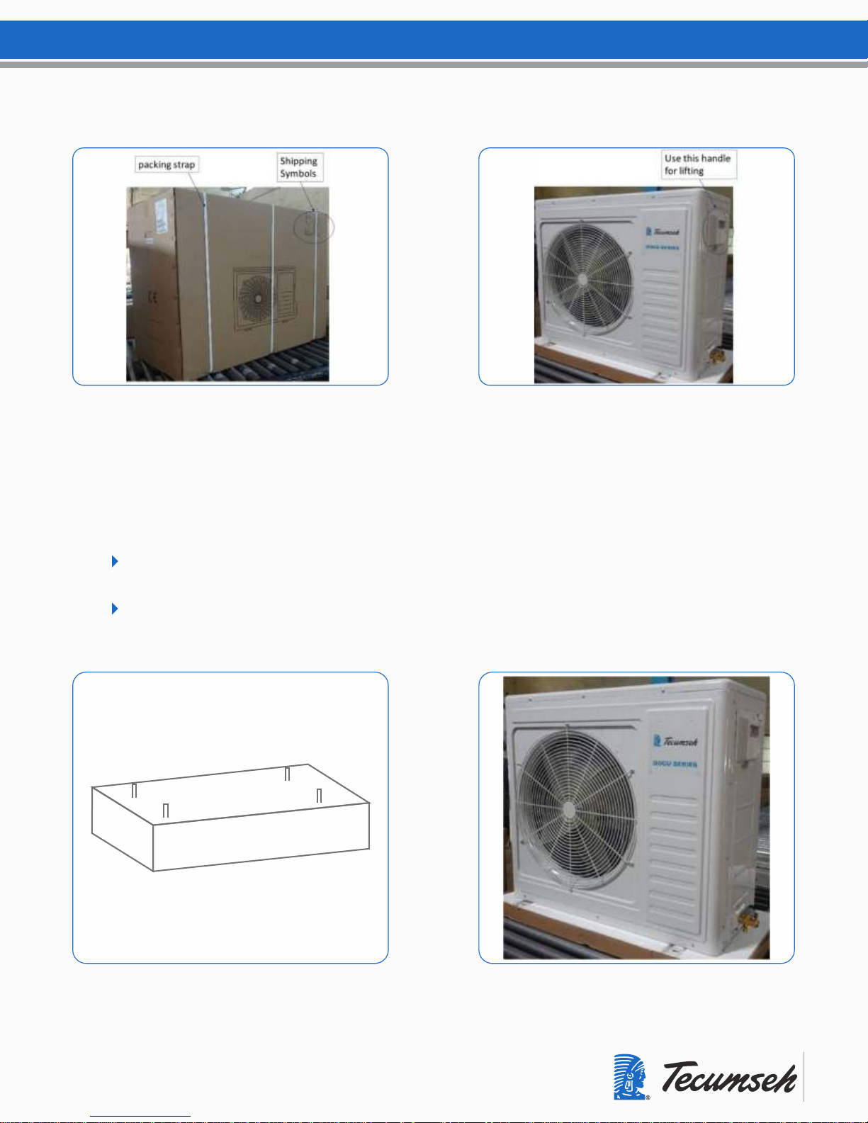
Don’t remove the carton box until the unit arrives at the destination.
Verify the shipping symbols on the packing box are in right direction.
Cut the packing straps and remove the packing carton box.
(refer the Picture-1 Picture-2)
While lifting proper measures should be taken to protect the enclosure panels.
Always keep the unit upright, laying the unit on its side or top may cause
the unit damage.
Care should be taken to locate the center of gravity of the unit before lifting,
as the compressor is the heaviest part of the unit may not be located in the
center of the unit base.
Never lift or displace the units with enclosure panels removed.
A ll the panels should be in place and properly tightened.
Page 7
7
ODCU MOUNTING OPTIONS.
7.1 FLOOR MOUNTING:
Make a concrete platform to the mounting dimension of M8 anchor bolt 4 Nos with M8
Plain washers.
Base surface should be leveled properly. (for mounting pitch dimensions refer
drawing.No. 1 & 2 on the page No. 4 & 5 of this booklet)
Page 8
8
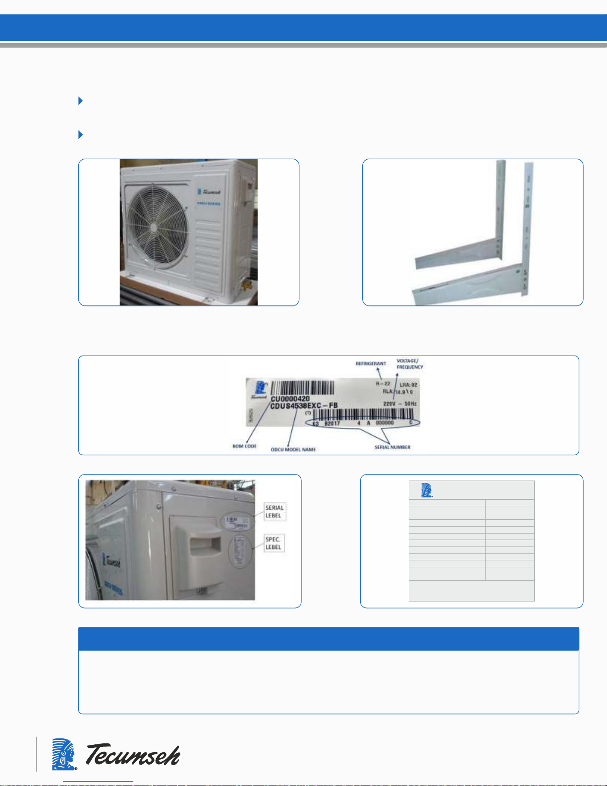
7.2 WALL MOUNTING:
ODCU unit can be mounted on the wall by using the M.S.Angle L – 2’x2’x8’ Frame
and fix to the wall.
M.S.Angle L – 2’x2’x8’ Frame not in the manufacturer’s scope of supply.
ODCU SERIAL/SPEC. LABEL & LOCATION
OUTDOOR
CONDENSING UNIT (CDU)
TECUMSEH PRODUCTS INDIA PVT.LTD
BALANAGAR TOWNSHIP, BALA NAGAR
www.tecumsehindia.com
CDU4542EXG-S
AWS4542EXG
3 Ph - 400 V - 50 Hz
35660
6.8
3635
R- 22 / 3500g
26.7 / 18.8
0.65 / 2.6
900x360x805
1059x500x875
68
CDU Model
Compressor Model
Power Supply
Cooling Capacity (btu/hr)
Nominal Current (a)
Power Input (w)
Max. Refrigerant Chargable
HP Pr. Switch Cut In/cut Out (Bar)
LP Pr. Switch Cut In/Cut Out ( Bar )
Outdoor Unit Dimension (mm)
Packing dimension (mm)
Outdoor Unit Weight ( kg )
Main power supply should always be disconnected and locked off to avoid accidental start up or electric
shock. Failure to do so could result in injury or death.
Some parts like condenser fins or some corners on the sheet metal parts are sharp and may potentially
cause injury. Use extra caution
WARNING
Page 9

9
To access the electrical connector, please unscrew the cover
(As shown in the picture-3)
In order that these units have the starting, operating and dependability characteristics
required of them, the compressor and its protective devices are designed for operation
within a specific minimum 90% and maximum 110% of the rated voltage. This voltage
range is defined in the following table
ELECTRICALS
Verify before any electrical installation if the voltage and phases of the supply satisfy
those required of the unit. Refer the below table for voltage code details.
Refer to “Maximum Continuous Current” to size the electrical wires, fuses and over
current protection devices.
A pump down cycle should be employed to control all these units as per the application
requirement. That is, solenoid valve for the liquid line. (Applicable for fully built models only).
Room thermostat is the scope of customer and installed by the qualified technician.
The wiring diagram shows all electrical components connected to the system. And in
case any component be added to the unit as a field supplied option then, the wiring
should follow the given wiring diagrams (shown in the page no. 10 & Affixed inside the
electrical cabinet/cover (See Picture-4)
CAUTION: Any non-compliance with voltage ranges and phase balances or any altering of
electrical components without Tecumseh written approval will void the warranty.
RATED VOLTAGE
XC
XG*
GH
GE
GF
220-240V @ 50 Hz 1 Ø
380-420V @ 50 Hz 3 Ø ; 460V @ 60 Hz 3 Ø *
230V @ 50 Hz 1 Ø
230V @ 50 Hz 1 Ø
400V @ 50Hz 3 Ø
VOLTAGE CODE
* Compressor Voltage Code: Operating frequency is 50/60 Hz but condensing
unit is compatible for 50 Hz only
Page 10

10
WIRING DIAGRAMS
WIRING DIAGRAM FOR ODCU-FB 1 PHASE MODEL
Legend.: Comp- Compressor, RU-Potential Relay, F, Mot-fan Motor, CCH-Crankcase
HPSW-High Pressure Switch, LPSW-Low Pressure Switch, LLSV-Liquid Line Solenoid Valve
E
L
N
1
2
3
4
5
6
7
8
E
BLUE
GREEN
BLACK
GREEN
BROWN
GREEN
BROWN
BROWN
BLUE
BLUE
RED
WHITE
RED
YELLOW
F, MOT
RUN
CAP
BLACK
START
CAP
BLACK
POTENTIAL
RELAY
BLACK
RED
CCH
HP/SW
(NC)
LP/SW
(NO)
LLSV
GREEN OR GREEN/YELLOW
COMP
S
R
C
WIRING DIAGRAM FOR ODCU - STANDARD 1 PHASE MODEL
Legend.: COMP- Compressor, RU-Potential relay, F,MOT-Fan Motor, CCH- Crankcase Heater,
HP SW-High Pressure Switch, LP SW-Low Pressure Switch, LLSV- Liquid Line Solenoid Valve,
E
L
N
1
2
3
4
5
6
7
8
E
BLUE
GREEN
BLACK
GREEN
BROWN
GREEN
BROWN
BROWN
BLUE
BLUE
RED
WHITE
RED
YELLOW
F, MOT
RUN
CAP
BLACK
START
CAP
BLACK
POTENTIAL
RELAY
BLACK
RED
CCH
HP/SW
(NC)
LP/SW
(NO)
LLSV
GREEN OR GREEN/YELLOW
COMP
S
R
C
E
1
2
3
N
4
5
6
7
8
9
E
CCH
BLACK
GREEN
BROWN
GREEN
BROWN
GREEN OR GREEN/YELLOW
HP/SW
(NC)
LP/SW
(NO)
BLUE
WHITE
RED
BLACK
BLUE
L1
L2
L3
COMP
BLUE
ORANGE
F. MOT
WIRING DIAGRAM FOR ODCU - STANDARD 3 PHASE MODEL
WIRING DIAGRAM FOR ODCU - FB 3 PHASE MODEL
Page 11

11
After all leak check procedures are completed, refrigerant lines that may be exposed to
high and low ambient temperatures should be insulated. The suction lines should be
insulated with an industry accepted material of no less than ¾” wall thickness.
In case, need more information, please contact Tecumseh representative.
CONNECTIONS OF SUCTION & LIQUID LINE
AND REFRIGERANT PIPING.
For the service end refrigerant piping connections for the evaporator or unit cooler, 3-way
service valves are used. The details of service valve is given in the page No. 4 & 5 of this
booklet.
In case, the suction line is up flow, then use one standard size smaller. A suction
trap should be installed at the base of suction risers. Long radius elbows should be
employed to minimize pressure losses.
To prevent oxidation and scale forming inside the tubes it is recommended to flow
dry nitrogen through the tubing during the brazing operations. A light flow of about
¼ CFM is sufficient.
Assurance of adequate velocity, thus ensuring oil return capability (the tube size
must be limited to maintain velocities no less than 750 fpm for horizontal and
down flow and no less than 1500 fpm for up flow)
Assurance of acceptable pressure drop (The tube size should be limited to
maintain pressure drop no greater than the equivalent of a 2°F temperature drop.)
Assurance of satisfactory sound level (the tube size should be limited to
maintain velocities no greater than 3000 fpm.)
Horizontal suction lines should be sloped downward in the direction of the
compressor at least ½” per 10’ of line.
Please use only refrigeration grade copper tubes & flare nuts.
Always keep the tubes free of moisture and dirt and remove any burrs present on the tube.
The selection of the suction line sizes should be guided by the following criteria:
PRESSURE CONTROLS (MINI PRESSURE SWITCHES)
Page 12

12
Always protect low (or dual) pressure control from excessive high pressure. It is recommended to disconnect
the low-pressure (or the low side of the dual pressure) control prior to pressurization.
WARRANTY
Follow the leak check procedure very carefully. Warranty will be voided if compressor fails as a result of
refrigerant leakage related problems. Leakage of refrigerant to the atmosphere has been identified as a
major source of global warming and ozone depletion.
SYSTEM FLUSHING, PURGING, AND PRESSURE
TESTING FOR LEAKS
A pressure leak test is mandatory and is to be performed for the complete refrigeration system, including the
ODCU, prior to system charging.
To thoroughly leak check the system, the system should be pressurized to a maximum of 150 psig with dry
nitrogen to the high and low side of the system. With the pressure equalized at 150 psig, a leak check should
be performed on EVERY joint in the system to ensure that no leaks are present. The initial charge may be
released.
The leak check procedure should then be repeated using a much more accurate means to determine that the
system is 100% free of leaks. Use of electronic leak detection equipment is highly recommended due to its
potential accuracy when used correctly in accordance with the manufacturer’s instructions. If trace amounts
of refrigerant are used, use only the refrigerant indicated on the serial label of the ODCU.
If trace amounts of refrigerant are used during the leak check procedure, this must be properly recovered and
disposed of in an appropriate manner to protect the environment.
As an added precaution, the leak check charge should be left in the system for no less than 12 hours without
loss of pressure.
Every joint in the system including, but not limited to, factory welds, flare nuts and pressure controls must be
leak checked. A leak free system is required for the installation to function correctly.
NOTE: odcu is leak checked by helium leak detection (HLD).
Failure to properly flush, purge, or pressure test a system for leaks can result in serious injury or death from
explosion, fire, or contact with acid-saturated refrigerant or oil mists.
Follow these precautions when flushing, purging or pressure testing a system for leaks:
ITEM CODE
CUT IN
BAR
CUT OUT
BAR PSIG PSIG
HP/LP BODY CONTACT
580066 18.8+1 276.4 26.7 + 0.7 392.5
HP
BLACK
CLOSED
580070 2.6 + 0.3 38.22 0.65 + 0.2 9.555
LP GREEN OPENED
REFRIGERANT
R22
R22
Page 13

13
Use flushing products according to the manufacturer’s instructions
To flush a system, use only dry nitrogen.
When pressure testing for leaks, use only regulated dry nitrogen or dry nitrogen plus trace amounts
of serial label refrigerant.
When purging or pressure testing any refrigeration or air conditioning system for leaks, never use
air, oxygen or acetylene. Oxygen can explode on contact with oil.
Acetylene can decompose and explode when exposed to pressures greater than
approximately 15 psig.
Combining an oxidizing gas, such as oxygen or air, with an HCFC or HFC refrigerant under
pressure can result in a fire or explosion. Use a pressure regulating valve and pressure gauges.
Commercial Cylinders of nitrogen contain pressures in excess of 2000 psig at 70°F. At pressures
much lower than 2000 psig, compressors can explode and cause serious injury or death. To avoid
over pressurizing the system, always use a pressure-regulating valve on the nitrogen cylinder
discharge. The pressure regulator must be able to reduce the pressure down to 1 to 2 psig and
maintain this pressure.
The regulating valve must be equipped with two pressure gauges:
One gauge to measure cylinder pressure
One gauge to measure discharge or downstream pressure
Use a pressure relief valve. (Not in the scope of manufacturer)
In addition to pressure regulating valve and gauges, always install a pressure relief valve. This can
also be frangible disc type pressure relief device. This device should have a discharge port at least
½” NPT size. The valve or frangible disc device must be set to 175 psig.
CAUTION
Do not pressurize the system beyond 150 psig field leak test pressure.
Disconnect nitrogen cylinder and release the pressure in the system before evacuating and
connecting a refrigerant container.
Nitrogen pressurizing method can be used for gross leak detection.
A more detailed leak check with refrigerant leak detectors is necessary.
Use only the refrigerant noted on the serial label of the unit.
Page 14

14
SYSTEM EVACUATION
Following the pressure testing for leaks, the system must be evacuated.
Use a vacuum pump (not a compressor) to draw a vacuum of 200 microns or less from
both sides of the system. Do not attempt to draw a vacuum on the system with the pump
connected only on the low side. The high side of the system should be interconnected with
the low side by using a minimum 3/8” OD copper tube. Use an electronic gauge to
measure the vacuum because a refrigeration gauge cannot provide an accurate reading
at this resolution.
Break the vacuum with dry nitrogen. These procedures should be performed at ambient
temperature above 18.33°C.
Note: Never use a compressor to evacuate a system. Instead, use a high-pressure
vacuum pump specifically designed for that purpose. Never start the compressor while it is
under a deep vacuum. Always break the vacuum with a refrigerant charge before
energizing the compressor. Failure to follow these instructions can damage the hermetic
terminal. As always, to avoid serious injury or death from terminal venting with ignition,
never energize the compressor unless the terminal cover is securely fastened.
WARRANTY
Warranty will be voided if compressor Follow the evacuation procedure very carefully.
fails as a result of moisture related problems.
SYSTEM CHARGING
Failure to properly charge the system can result in serious injury or death from
explosion or fire. Follow these precautions when charging a system:
Do not operate the compressor without charge in the system.
Operating the compressor without a charge in the system can damage the hermetic
terminal. To avoid serious injury or death from terminal venting with ignition, never
energize the compressor unless the protective terminal cover is securely fastened.
Use only the serial label refrigerant when charging the system. Using a different
refrigerant can lead to excess system pressure and an explosion. Use of a refrigerant
other than the serial label refrigerant will void the compressor warranty.
Do not overcharge a refrigeration or air conditioning system.
Overcharging a refrigeration or air conditioning system can result in explosion. To avoid
serious injury or death, never overcharge the system. Always use proper charging
techniques.
Limit charge amounts to those specified on the system equipment serial label or in the
original equipment manufacturer’s service information.
Overcharging the system immerses the compressor motor, piston, connecting rods,
and cylinders in liquid refrigerant. This creates a hydraulic block preventing the
compressor from starting. The hydraulic block is also known as locked rotor.
WARRANTY
Use of a refrigerant other than those listed on the serial label will void the compressor
warranty.
Page 15

15
APPROVED HERMETIC COMPRESSOR OILS
Hermetic compressors are charged with optimum oil that will be adequate for close- coupled
systems designed in accordance with good engineering practice.
Some System designs containing unusual evaporators or extensive interconnecting
pipes,may require additional oil. However, since excess oil can also damage compressors,
care should be taken not to exceed the oil charge amounts specified. For more detail contact
Tecumseh sales representative.
REFRIGERANT APPROVED COMPRESSOR OILS
R404A
R22
Mineral Oil
Polyol Ester (POE)
SYSTEM START-UP PROCEDURE
Check the electrical connections if they are properly attached and secured.
Check the electrical supply versus nameplate specifications.
Check if the Voltage deviation is within the specified range.
Check all mechanical and electrical connections if they are properly tightened and secured.
Compressor mounting parts, fan motor mounting screws, fan blade tightening screw, shroud
electrical boxes etc.
Check that the safety and pressure controls are connected and set correctly.
Check that the suction and liquid Service valves are connected properly.
Check by isolating the compressor motor if the control circuit including thermostat and
solenoid valve (if used) is wired and operates correctly.
Confirm that the system has been properly leak tested, evacuated and charged. If the system
has been previously charged then make sure that the crank case heater is turned on at least
24 hours prior to start up, otherwise warm up the compressor bottom shell to assure that the
refrigerant will not cause damage to the compressor due to the slugging condition. Do not
attempt to warm up the compressor by applying a flame to the crankcase.
Turn on the electrical power to the condensing unit and unit cooler(s) or freezer(s).
The compressor will start when the low-pressure control closes.
Always re-assemble the enclosure panels when start-up job is completed. Make sure all
panels are secure and panel screws are properly tightened
Page 16

16
OPERATIONAL CHECKOUT PROCEDURE
Check if the voltage deviation is within the specified range.
Check that the ampere draw doesn’t exceed the amperage specified on the nameplate.
Check the phase unbalance if there is a three-phase connection. Unbalance should not
exceed 2%.
Check proper phase connections on three phase models only.
Check that the discharge and suction pressures are within limits.
Check the liquid flow in the liquid sight glass. (For fully built models only)
Measure compressor and evaporator superheats. Make proper adjustments if necessary.
Check (if equipped) the defrost and timer controls for proper initiation
and termination settings.
If any malfunction is observed at any time during either start-up or operational checkout
procedures, stop the unit, disconnect power and correct the malfunction accordingly.
Re-check after 48 hours of operation for loose electrical connections, abnormal vibrations
that may have developed, refrigerant charge and correct any probable malfunction observed.
Always re-assemble the enclosure panels when operational check out procedure is
completed. Never leave loose or not properly tightened panels.
MAINTENANCE (ODCU)
Inspect for abnormal indications, vibration, noise.
Inspect and measure temperature of lower housing and determine that it is warm. Make sure
that the upper housing is not sweating.
Inspect all electrical parts for loose connections. Tighten them if necessary
Inspect insulation status of all wires.
Inspect contactors and make sure that they are functioning correctly.
Inspect the fan motors, make sure that the fan blades are tight and all mounting
joints are tight.
Check the crankcase heaters for proper operation. Use an ampere meter to check
for current draw.
The refrigeration systems should be scheduled for check-up, inspection and maintenance
service, at least twice a year, in order to assure a trouble-free operation for many years.
CAUTION: When servicing these systems, the main power supply must be disconnected
and locked off. Extreme care must be used when servicing a unit that requires the power
to be “ON”.
Page 17

17
Inspect refrigerant charge in the in the system for any leakages by measuring suction & liquid
line pressures.
Check and make sure that the condenser surface is clean and free of dirt and debris.
Check all refrigeration piping. Make sure that all mechanical joints and flare nuts are tight.
Always re-assemble the enclosure panels when maintenance job is completed. Never
leave loose or not properly tightened panels.
ATTENTION!
Make sure all screws are re-tightened before start-up
Make sure all wires are connected as per wiring diagram
TROUBLE SHOOTING
Basic troubleshooting tips for compressor are provided in the appendix. For more more help,
please contact application engineering or Tecumseh sales representative.
The unit should be inspected before unpacking for signs of damage or loss and packing list
should be checked against material received to ensure shipment is complete. A report should be
compiled and a claim must be filed with the freight carrier if shipping damage is discovered.
If damages to the packing are obvious but no visible damage on the unit or the parts are noted
then a report should be compiled and a claim for “probable hidden damages” should be filed
with the transportation carrier. The manufacturer is not responsible for damages or loss caused
by the transportation carrier.
NOTE: Tecumseh reserves the right to change any information in this publication at any time.
This document is not intended to replace the training required for professional service
personnel, replace other information available from refrigeration and air conditioning equipment
manufacturers. This trouble-shooting chart is not designed to replace the training required for a
professional refrigeration service person, nor is it comprehensive. As a trained professional, for
your safety and others always be aware of the following issues:
Terminal venting and electrocution
Properties of refrigerant and other chemicals involved
Proper compressor removal methods
Proper system flushing, purging and leak testing methods
Proper system evacuation method
Proper system charging methods
Start capacitor overheating issues
Page 18

18
TROUBLESHOOTING CHART
Complaint
Possible Causes
Too much current passing through thermal protector
Extra sources of current draw
Compressor motor winding shorted
A, COMPRESSOR NOT STARTING – NOT HUMMING.
System component not functioning properly:
Control/contactor stuck in open position
Control off due to cold location
Thermostat not functioning properly
Line disconnect switch open
Circuit breaker tripped or fuse open or removed
Compressor motor winding open or short
Wiring improper or loose
Compressor motor has a ground fault (also known as short circuit to ground)
B, COMPRESSOR NOT STARTING HUMS BUT
TRIPS ON THERMAL PROTECTOR
Improperly wired
Low voltage to compressor
System component, such as thermostat or contractor may not function properly
Compressor electrical problems
Compressor motor winding open or shorted
Faulty relay. Or not functioning properly.
Faulty start capacitor or Not working properly
Liquid refrigerant in compressor.
C. COMPRESSOR STARTS AND RUNS, BUT SHORT CYCLES
ON THERMAL PROTECTOR
Page 19

19
System components, such as thermostat, control or contactor, not functioning properly
and extra sources of current draw.
High pressure cut-out due to
Insufficient air or water supply
Overcharge of refrigerant
Air in system
Water leak into refrigerant side of a water-utilizing system
Low pressure cut-out due to
Liquid line solenoid leaking
Undercharge of refrigerant
Restriction in expansion device
REFRIGERATION ACCESSORIES.
INSTRUCTIONS FOR THE FILTER DRIER SOLDER TYPE.
Low voltage to compressor (single phase) or unbalanced voltage (three-phase)
Compressor electrical problems, such as thermal protector or run capacitor not working properly
Discharge pressure too high
Suction pressure too high
Return gas too warm
D. UNIT RUNS OK BUT RUN CYCLE IS SHORTER
THAN NORMAL (DUE TO HP/LP CUT OUT SWITCHES)
Page 20

20
IINSTRUCTIONS FOR THE SIGHT GLASS SOLDER TYPE
Page 21

21
INSTRUCTIONS FOR THE SOLENOID VALVE ( SOLDERING TYPE )
Page 22

22
Page 23

23
STACKING OF THE UNIT
!. For transportation and storage the maximum stack limit is 1+1 only
!!. Care must be taken while transportation. If require, additional wooden board to be nailed.
CONTACT INFORMATION
Please write us back with your valuable Feedback to our sales
representative The information in this booklet are
Subjected to change without notice due To continous
improvements.
Mail your feedback to: info@tecumsehindia.com
Page 24

©2018 Tecumseh Products Company. All Rights Reserved.
TECUMSEH INDIA
SALES AND MARKETING
Tecumseh Products India Pvt. Ltd.,
Trading Division, Balanagar Township,
Hyderabad-500037
Ph. No. 040-23720034
040-30116958
SALES SERVICES
56, WHS, Furniture Block, Kirti Nagar,
New Delhi-110 015
Ph. No: 011-25190092; 25432419
Kaushik Chamber, Plot No. 64, Sector-19A,
Vashi, Navi Mumbai-400705
Ph. No: 022 65176929
Old No. 37, New No. 6, Arcot Road, VADAPALANI,
Chennai-600 026 (Supra CFA)
23652244, 23652300
4/2/1A, Rustomjee Street, Kolkata-700019
Ph. No: 033-24606026
Fax No. 033-24606027
Gala No.41, Amul Estate, Opp. Marium Masjid,
Near Sanand-Sarkhej, Railway Crossing, Sarkhej,
Ahmedabad-380220
Ph. No. 079-26823423
Plot No. 211, Sector 29D, Iron market, Chandigarh
Ph. No: 0172-2654481
302, Navlakha, Opp: Prakash Nagar, Nemawar road,
Indore-452001 (MP)
Ph. No: 0731-2400554
For more information on products by Tecumseh,
please visit our website: www.tecumseh.com
 Loading...