

Page 1

TECUMSEH
T E C H N I C I A N ' S H A N D B O O K
This manual covers the following basic type or model
numbers dependent on age of product: AH520, AH600,
AV520, AV600, HSK600, TVS600.
This manual covered many engines under an Old form of
Identification which will need to be reviewed as well.
TYPE / SPECIFICATION NUMBER 638-670 1398-1642 and
Craftsman 200 Series Models.
2-CYCLE
ENGINES
Page 2

Contents
Page Page
GENERAL INFORMATION ...................................... 1
ENGINE IDENTIFICATION................................... 1
INTERPRETATION OF MODEL NUMBER .......... 1
ENGINE CARE ......................................................... 2
SHORT BLOCKS .................................................. 2
STORAGE: ............................................................ 2
TUNE-UP PROCEDURE ...................................... 3
EXHAUST PORT CLEANING .............................. 3
2-CYCLE THEORY OF OPERATION ...................... 4
OPERATION OF PISTON PORT STYLE ............ 4
OPERATION OF REED PORTED STYLE
WITH LOOP SCAVENGING.............................. 4
TERMS .................................................................. 4
EXHAUST OR SCAVENGE PHASE .................... 4
PORTS .................................................................. 4
EXHAUST PORTS ................................................ 4
THIRD PORT ........................................................ 4
REED VALVE ........................................................ 4
LUBRICATION ...................................................... 4
AIR CLEANERS, CARBURETORS, GOVERNORS
AND LINKAGE ......................................................... 5
AIR CLEANERS .................................................... 5
POLYURETHANE-TYPE AIR CLEANER ............ 5
KLEEN-AIRE® SYSTEM ......................................5
PAPER-TYPE AIR CLEANER SERVICE ............. 5
GENERAL CARBURETOR INFORMATION ........... 6
CARBURETOR IDENTIFICATION ....................... 6
FLOAT-TYPE CARBURETORS ........................... 6
DIAPHRAGM (PRESSURE DIFFERENTIAL)
CARBURETORS ...................................................6
OPERATION.......................................................... 7
CARBURETOR SERVICE .................................... 7
THROTTLE............................................................ 7
CHOKE .................................................................. 8
ADJUSTING SCREWS ......................................... 8
FUEL BOWL RETAINING NUT ............................ 8
CARBURETOR VENTING.................................... 8
HIGH TILT FLOAT STYLE .................................... 8
FUEL BOWL .......................................................... 8
FLOAT ................................................................... 8
INLET NEEDLE AND SEAT (FLOAT
CARBURETORS) .............................................. 9
NEEDLE AND SEAT OPO-OFF TEST ................ 9
FLOAT HEIGHT SETTINGS ................................. 9
PRIMER BULB .................................................... 10
CLEANING CARBURETOR BODY.................... 10
DIAPHRAGMS .................................................... 10
INLET NEEDLE AND SEAT ............................... 11
FUEL INLET FITTING......................................... 11
PRIMER BULB (DIAPHRAGM
CARBURETOR) ................................................ 11
CARBURETOR CHECK VALVE ......................... 11
CARBURETOR SERVICE PROCEDURE ......... 12
EMISSIONIZED DIAPHRAGM CARBURETION13
OUTBOARD CARBURETORS .............................. 13
OUTBOARD CONTROL PANEL ........................ 14
CARBURETOR ADJUSTMENTS .......................... 15
IDLE SPEED ADJUSTMENT ............................. 15
FLOAT TYPE-FIXED MAIN, IDLE ADJUST ...... 15
DIAPHRAGM - SINGLE AND DUAL
ADJUSTMENT ..................................................15
TROUBLESHOOTING CARBURETION ............... 16
FLOAT CARBURETOR CHECKS ...................... 16
CHECKS FOR DIAPHRAGM ............................. 16
STANDARD SERVICE CARBURETORS..............17
FUEL FITTING .................................................... 17
INLET FUEL FITTING.........................................17
CHOKE SHAFT ................................................... 17
THROTTLE LEVER ................................................ 17
IDLE SPEED ADJUSTMENT SCREW .................. 17
GOVERNORS AND LINKAGE .............................. 18
AIR VANE GOVERNORS ...................................18
OPERATION........................................................ 18
LINKAGE INSTALLATION..................................... 18
REWIND STARTERS, ELECTRIC STARTERS
AND ALTERNATORS............................................. 20
REWIND STARTERS.......................................... 20
COMPONENTS................................................... 20
ROPE SERVICE ................................................. 20
STYLIZED REWIND STARTER ......................... 21
VERTICAL PULL STARTER HORIZONTAL
ENGAGEMENT TYPE ........................................ 22
STYLIZED REWIND STARTER WITH PLASTIC
RETAINER ........................................................ 23
VERTICAL PULL STARTER, VERTICAL
ENGAGEMENT TYPE ......................................24
REWIND STARTER MOUNTED IN HOUSING . 25
ELECTRIC STARTERS .......................................... 26
DRIVE ASSEMBLY SERVICE ............................ 26
STARTER CHECKING AND SERVICE ............. 27
CHECK FIELD..................................................... 27
ARMATURE CHECK........................................... 27
TROUBLESHOOTING STARTERS ....................... 27
ALTERNATORS ...................................................... 28
CHECKING THE SYSTEM ................................. 28
FLYWHEEL (INSIDE-EDGE) BRAKE SYSTEM ... 29
INSIDE EDGE SYSTEM ..................................... 29
COMPONENTS................................................... 29
SERVICE .............................................................29
CONTROL CABLE ..............................................30
Copyright © 1994 by Tecumseh Products Company
All rights reserved. No part of this book may be reproduced or transmitted, in any form or by any
means, electronic or mechanical, including photocopying, recording or by any information storage and
retrieval system, without permission in writing from T ecumseh Products Company Training Department
Manager.
i
Page 3

Page
Page
IGNITION ................................................................. 31
IGNITION OPERATION (Pre- 1985
Production)........................................................ 31
MAGNETO IGNITION ......................................... 31
CONTACT POINTS............................................. 31
CONDENSER .....................................................31
OPERATION OF THE TECUMSEH
MAGNETO IGNITION....................................... 31
SOLID STATE IGNITION (1985 to Present)...... 32
SOLID STATE IGNITION OPERATION ............. 32
IGNITION SERVICE ............................................... 33
SPARK PLUG SERVICE ....................................33
FLYWHEEL REMOVAL AND SERVICE............. 33
FLYWHEEL MAGNETS ......................................33
FLYWHEEL KEYS............................................... 34
ADAPTER KEY TO FLYWHEEL ASSEMBLY.... 34
FLYWHEEL SLEEVE .......................................... 34
FLYWHEEL TORQUE......................................... 34
REPLACING MAGNETO BREAKER POINTS .. 34
CONDENSER CHECK .......................................34
IGNITION COIL ................................................... 34
IGNITION TIMING .............................................. 34
FIXED TIME SPEED (EXTERNAL COIL) .......... 36
SOLID STATE (CDI) ........................................... 36
OTHER IGNITION SYSTEMS ............................ 36
OUTBOARD TIMING .............................................. 38
OUTBOARD TIMING (STANDARD IGNITION) . 38
OUTBOARD TIMING (SOLID STATE)............... 39
CYLINDERS & INTERNAL COMPONENTS ......... 41
PISTON & RING SERVICE ................................41
CONNECTING ROD SERVICE .............................. 42
NEEDLE BEARINGS .......................................... 42
CRANKSHAFT, BEARING AND OIL SEAL
SERVICE .................................................................43
NEEDLE BEARINGS .......................................... 43
OIL SEALS .......................................................... 43
ONE PIECE SEALS ............................................ 43
THREE PIECE SEALS ....................................... 44
OUTBOARD SEAL SERVICE ............................ 44
CYLINDERS, REEDS & COMPRESSION
RELEASE ................................................................ 45
CYLINDER & HEAD SERVICE .......................... 45
GASKETS............................................................ 45
REED VALVES.................................................... 45
AUTOMATIC COMPRESSION RELEASE
(DOUBLE REED TYPE) .................................45
AUTOMATIC COMPRESSION RELEASE
(SINGLE REED TYPE)................................... 45
CYLINDER EXHAUST PORTS ..........................46
TROUBLESHOOTING............................................ 47
ENGINE FAILS TO START OR STARTS
WITH DIFFICULTY ............................................. 47
ENGINE KNOCKS .............................................. 47
ENGINE MISSES UNDER LOAD ......................48
ENGINE LACKS POWER................................... 48
ENGINE OVERHEATS ....................................... 48
ENGINE SURGES OR RUNS UNEVENLY ....... 49
ENGINE VIBRATES EXCESSIVELY ................. 49
SPECIFICATIONS .................................................. 50
ENGINE TYPE NUMBER AND LETTER
REFERENCE ...................................................50
SEARS CRAFTSMAN CROSS REFERENCE ...... 51
TABLE OF SPECIFICATIONS ....................... 52 - 61
TABLE OF TORQUE LIMITS ................................. 62
EDUCATIONAL MATERIALS AND TOOLS ......... 63
AVAILABLE TECHNICIAN'S HANDBOOKS...... 63
AVAILABLE FOREIGN TECHNICIAN'S
HANDBOOKS .................................................. 63
TOOL KIT 670195D................................................ 64
TOOLS..................................................................... 65
This manual contains information on Tecumseh Engines built to comply
with emission regulations. As a technician it is unlawful to modify or
cause a change in the original calibration of these engines. All speed
adjustments must remain within the limits that are specified for each
engine, and are not to exceed the maximum. Any deviation must be
specifically approved by Tecumseh Products Company.
ii
Page 4
GENERAL INFORMATION
ENGINE IDENTIFICATION
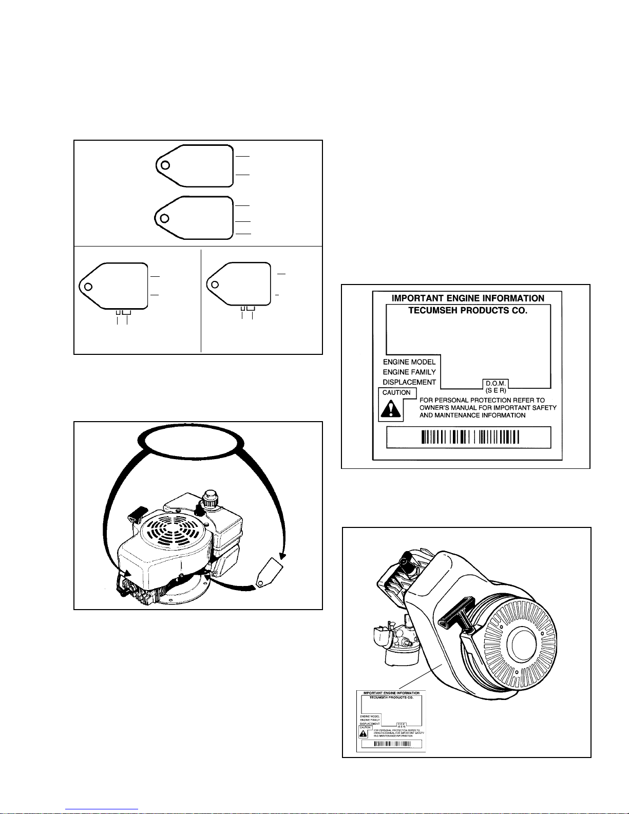
Tecumseh has used two different methods of identifying
2 cycle engines. The first method was used until the
mid 1980's using the base model number with a type
number. The type number was used to identify variations
for the OEM's specific needs (Fig. 1)
FRONT SIDE
REVERSE SIDE
(BUILD DATE)
1401J
TECUMSEH
6219
YEAR 219th DAY
1976 or Aug. 6th
TYPE
SERIAL
NUMBER
T-670
TECUMSEH
6874603
The second method was put in place to standardize
2 cycle and 4 cycle engine identification. The type
number has now become the specification number,
which is preceded by the engine model as illustrated
in Figure 2 and 3.
TYPE
SERIAL
NUMBER
1975 YEAR
30th DAY
5th. MONTH
5 30 75
(MAY)
670-100
TECUMSEH
62290322
YEAR 229th DAY
1976 or Aug. 17th
TYPE
SERIAL
NUMBER
1
Following the engine size are the engine specification
numbers which are used for identification when ordering
parts.
The final set of numbers are the date of manufacture
(D.O.M.).
Example: HSK600 1688S
HSK - Horizontal Snow King
600 - 6 Cubic Inch displacement
1688S - Specification number
8023B - Serial number D.O.M. (date of manufacturing
previously serial number)
8 - First digit is the year of manufacturing
(1998)
023 - Indicates the calendar day of the year (23th
day or Jan. 23, 1998)
B - Represents the line and shift on which
the engine was built at the factory
FUEL REGULAR UNLEADED
FUEL/OIL MIX 32:1
HSK600-1688S
8023B
TVS600-661030M 7352
TVS600-
7352
661030M
2
INTERPRETATION OF MODEL NUMBER
The letter designations in a model number indicates
the basic type of engine.
AH - Aluminum Horizontal
AV - Aluminum Vertical
BV - Outboard Vertical
HSK - Horizontal Snow King
TVS - Tecumseh Vertical Styling
3
Tecumseh engine model, specification, and D.O.M.
number are now located on a decal adhered to the
blower housing.
FUEL REGULAR UNLEADED
FUEL/OIL MIX 32:1
HSK600-1688S
8023B
The numbers that follow the letter designations indicate
the horsepower or cubic inch displacement.
4
1
Page 5
ENGINE CARE
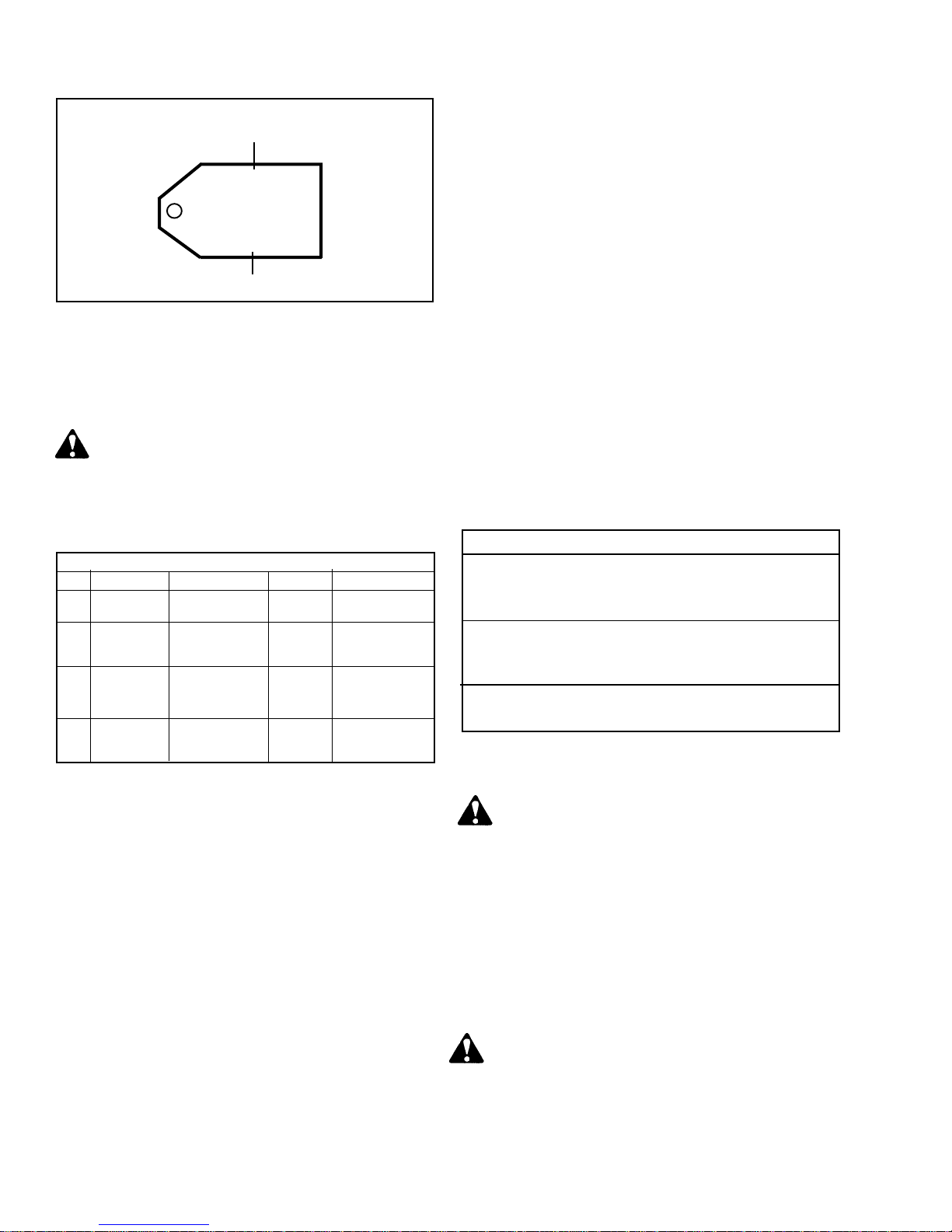
SHORT BLOCK IDENTIFICATION TAG
SBV OR SBH IDENTIFICATION NUMBER
SBV-2316
SER 4291
SERIAL NUMBER
SHORT BLOCKS
New short blocks are identified by a tag marked S.B.H.
(Short Block Horizontal) or S.B.V. (Short Block Vertical).
Original model identification numbers of an engine
should always be transferred to a new short block
for correct parts identification.
THIS SYMBOL POINTS OUT IMPORTANT
SAFETY INSTRUCTIONS WHICH IF NOT
FOLLOWED COULD ENDANGER THE
PERSONAL SAFETY OF YOURSELF AND
OTHERS. FOLLOW ALL INSTRUCTIONS.
ENGINE FUEL MIX
U.S. U.S. METRIC METRIC
Amount of Oil Amount of Oil
Gasoline To Be Added Petrol To Be Added
24:1 1 Gallon 5.3 oz. 4 Liters 167 ml
2 Gallons 10.7 oz. 8 Liters 333 ml
32:1 1 Gallon 4 oz. 4 Liters 125 ml
2 Gallons 8 oz. 8 Liters 250 ml
50:1 1 Gallon 2.5 oz. 4 Liters 80 ml
2 Gallons 5.0 oz. 8 Liters 160 ml
Using fuel that is not fresh will cause engines to be
hard starting, especially in cold temperatures.
Clean gas cap, tank and fuel container spout when
filling fuel tank, to assure that dirt will not get into
fuel system.
If gasohol is used, special care is required when the
engine is to be stored for extended periods.
ENGINE OIL. Use Clean, high quality 2 CYCLE OIL.
NMMA TC-WII, or TC-W3.
FUEL/OIL MIX. Follow fuel and engine oil requirements
listed in the Owners Manual. Disregard conflicting
instructions found on oil containers.
NOTE: Sears Craftsman models use a 40:1 mix which
is acceptable.
NOTE: ALWAYS DOUBLE THE AMOUNT OF OIL FOR
THE FIRST GALLON OF MIX FOR ENGINE BREAK
IN.
To assure thorough mixing of oil and gasoline, fill
container with gasoline to one quarter full, add oil as
recommended, shake container vigorously and then
add remainder of gasoline. Do not mix directly in
engine or equipment fuel tank.
TWO-CYCLE FUEL/OIL MIX RATIOS
24:1
AV520 All Basic Specifications 670 & 653
AV600 All Basic Specifications 600-10 & Up
32:1
TVS600 All Specifications
AH600
50:1
HSK600
STORAGE:
FUELS. Tecumseh Products Company strongly
recommends the use of fresh, clean, UNLEADED regular
gasoline in all Tecumseh Engines. Unleaded gasoline
burns cleaner, extends engine life and promotes good
starting by reducing the build up of carbon deposits.
Premium gas or gasohol containing no more than 10%
ethanol can be used if unleaded fuel is not available.
NOTE: NEVER USE GASOLINE CONTAINING
METHANOL, GASOHOL CONTAINING MORE THAN
10% ETHANOL, UNLEADED REGULAR GASOLINE
CONTAINING MORE THAN 15% M.T.B.E. OR ETBE,
GASOLINE ADDITIVES, OR WHITE GAS BECAUSE
ENGINE/FUEL SYSTEM DAMAGE COULD RESULT.
NOTE: In countries where unleaded gasoline is not
available, regular gas can be used.
Make sure that gasoline and oil are stored in clean,
covered, rust free containers. Dirt in fuel can clog
small ports and passages in the carburetor. Use fresh
gasoline only. Gasoline standing for long periods of
time develop a gum that will result in fouled spark
plugs, clogged fuel lines, carburetors and fuel screens.
2
NEVER STORE ENGINE WITH FUEL IN TANK
INDOORS OR IN ENCLOSED, POORLY
VENTILATED ENCLOSURES WHERE FUEL
FUMES MAY REACH AN OPEN FLAME, SPARK
OR PILOT LIGHT AS ON A FURNACE, WATER
HEATER, CLOTHES DRYER, ETC.
If engine is to be stored over 30 days, prepare for
storage as follows:
1. Remove all gasoline from fuel tank to prevent gum
deposits from forming in tank and other fuel system
components, causing possible malfunction of the
engine.
DRAIN FUEL INTO APPROVED CONTAINER
OUTDOORS, AWAY FROM OPEN FLAMES.
Run engine until fuel tank is empty and engine
stops due to lack of fuel.
Fuel stabilizer (such as Tecumseh's Part No.
730245) is an acceptable alternative in minimizing
the formation of fuel gum deposits during storage.
Page 6
Add stabilizer to fuel in fuel tank or storage container.
Always follow mix ratio found on stabilizer container.
Run engine at least 10 minutes after adding stabilizer
to allow it to reach carburetor.
If gasohol has been used, complete preceding
instructions and then add a small amount, one
pint or less, of unleaded regular automotive gasoline
properly mixed with the specified lubricating oil
and run the engine until the fuel tank is empty
and the engine stops due to lack of fuel.
2. Pull starter handle slowly until resistance is felt
due to compression pressure, then stop. Release
starter tension slowly to prevent engine from
reversing due to compression pressure. This position
will close both the intake and exhaust ports to
prevent corrosion of the piston and the cylinder
bore.
3. Clean unit by removing any dirt from exterior of
the engine and equipment.
TUNE-UP PROCEDURE. The following is a minor tuneup procedure. Repair procedures for this engine and
its components are listed in this manual if the engine
does not perform to satisfaction after tune-up is
performed.
8. Fill tank with the proper fuel/oil mix.
9. Start the engine, allow it to warm up 5 minutes,
then adjust carburetor and engine R.P.M. according
to Tecumsehs recommendations.
Snow King® engines should be run in outdoor
temperatures for engine adjustments.
NOTE: Emissionized engines have non-adjustable
carburetors in compliance with CARB (California Air
Resource Board) and U.S. EPA (United States
Environmental Protection Agency). These engines can
not be modified without specific authorization.
COMPRESSION
RELEASE
PASSAGE
CAUTION: Remove spark plug wire before doing
any service work on engine.
1. Service or replace air cleaner as necessary.
NOTE: Snow King® engines do not use an air filter
due to the clean operating environment and to
prevent filter freeze-up.
2. Remove blower housing, clean all dirt, grass or
debris from air intake screen, cylinder cooling fins,
and carburetor governor levers and linkage.
3. Remove carburetor, clean and install a carburetor
kit, make adjustment presets where needed. Presets
are found in the carburetor section of this manual.
Make sure fuel tank, fuel filters and fuel lines are
clean. Reinstall carburetor, replacing any worn
or damaged governor springs or linkage. Make
proper governor adjustment. Adjustments are found
in the manual under governor linkage and
adjustment and engine reassembly.
4. Replace the spark plug with a correct equivalent.
5. Make sure all ignition wires are properly routed,
so they will not rub on flywheel. Inspect all ignition
wires for abrasion or damage. Remove flywheel
and check flywheel key, reinstall flywheel, torque
flywheel nut to specifications. Set air gap between
solid state module and flywheel at .0125'. Air gap
gauge, part no. 670297 may be used.
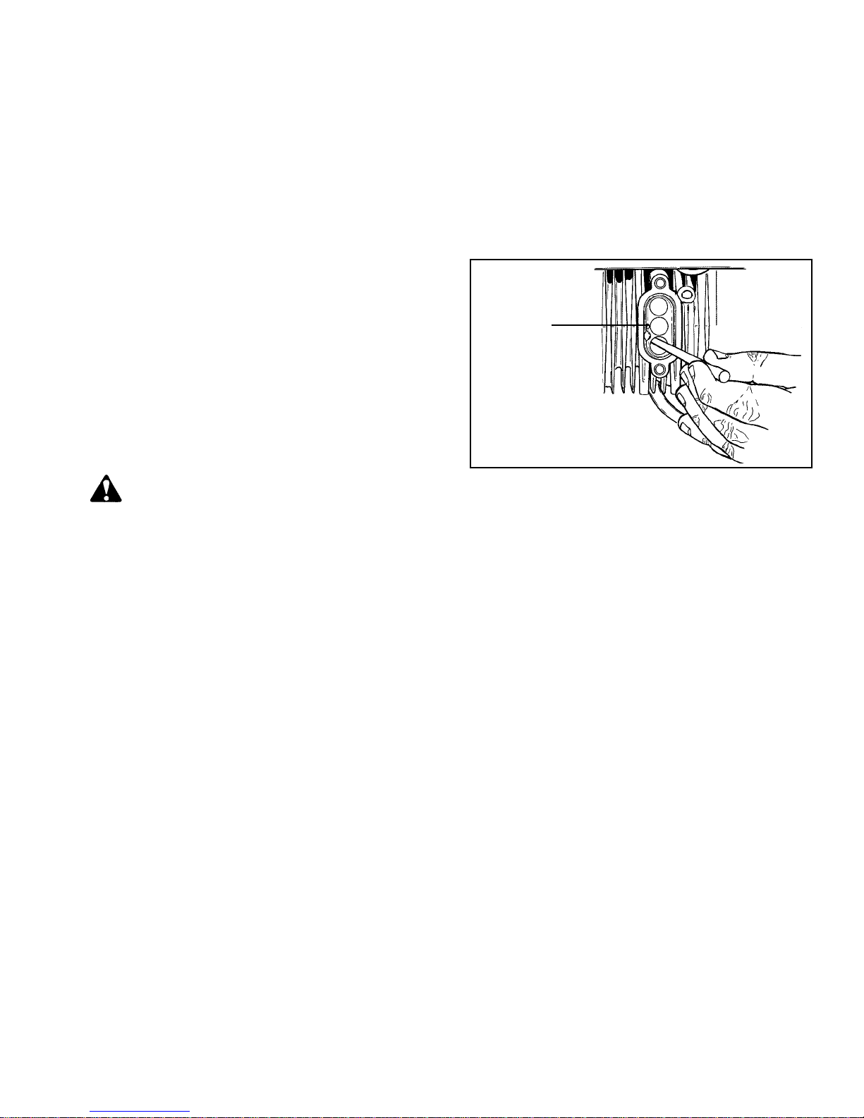
EXHAUST PORT CLEANING. The exhaust ports should
be cleaned after each seventy-five (75) to one hundred
(100) hours of use.
Before cleaning the ports place the piston in the Bottom
Dead Center position. Then clean the ports using a
pointed 3/8' diameter wooden dowel or similar tool.
Be sure not to scratch the port area. Also remember
to remove all the loose carbon particles from the engine.
NOTE: When cleaning the exhaust ports, check and
clean the compression release passage.
6. The engine must be firmly mounted to the associated
equipment. On rotary lawnmowers, make sure blade
is properly balanced and correctly torqued. See
disassembly section for flywheel removal and air
gap setting procedure.
7. Make sure all remote linkage is properly adjusted
for operation.
3
Page 7
2-CYCLE THEORY OF OPERATION
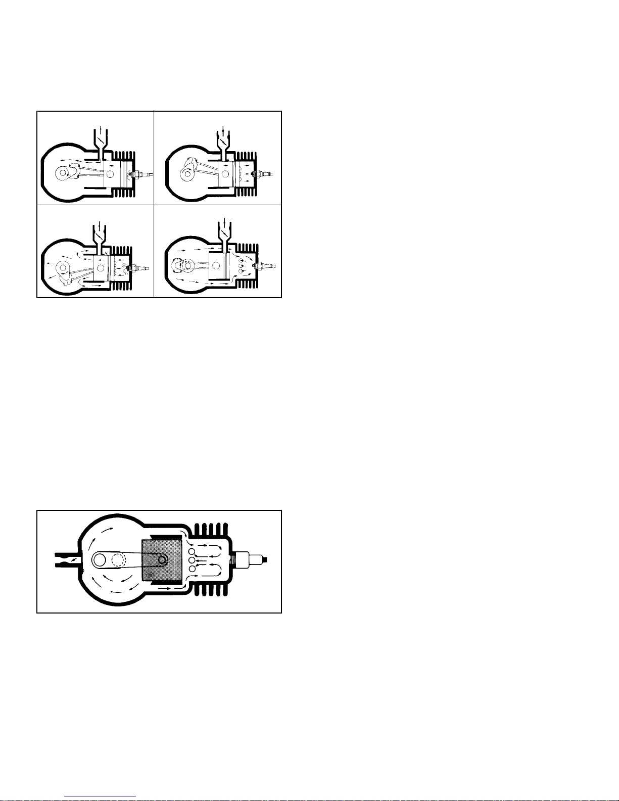
Air cooled 2-cycle engines differ from 4-cycles by having
one power stroke for every revolution of the engine
versus every other stroke on 4-cycles.
INTAKE AND IGNITION
1.
3.
OPERATION OF PISTON PORT STYLE.
A low pressure area is created in the crankcase as
the piston moves upward to compress the air/fuel mixture
in the cylinder. When the piston moves far enough to
uncover the intake port, the air/fuel mixture from the
carburetor flows into the engine crankcase due to higher
pressure atmospheric air. Just before the piston reaches
top dead center (TDC), the spark plug ignites the air
/ fuel mixture in the cylinder.
The expanding combustion gases force the piston down.
The downward piston travel causes a pressure buildup
in the crankcase. The piston uncovers the exhaust
port first, followed by the transfer ports. The exhaust
flows out the exhaust port while the pressurized air/
fuel mixture enters the cylinder from the crankcase
through the transfer ports. As the piston travels upward
the sequence is repeated.
POWER
2.
4.
COMPRESSION
As the mixture flows into the combustion chamber
through the transfer ports, it collides and is directed
to the top of the combustion chamber looping when
it strikes the cylinder head, thus forcing all spent gases
out through the open exhaust ports.
TERMS. Listed are common terms often referred to
on 2-cycle engines.
EXHAUST or SCAVENGE PHASE. The burned gases
must be cleared out of the combustion chamber and
replaced by a fresh charge of fuel-air mixture through
the intake ports. The exhaust passes out through the
exhaust ports into the outside air.
PORTS. Openings in the cylinder allow gases to pass
into and out of the combustion chamber. The ports
are opened or closed by the upward and downward
movement of the piston.
EXHAUST PORTS. Allow the burned gases to pass
out of the combustion chamber.
THIRD PORT (Sometimes called piston port). A third
port is for entry of the fuel-air and oil mixture to the
crankcase. From the crankcase the fuel-air mixture
enters the combustion chamber through the intake
ports. The third port is controlled by the piston skirt.
REED VALVE. A reed valve is activated by crankcase
pressure or vacuum. A decrease in crankcase pressure
opens the reed allowing the fuel air and oil mixture
to enter the crankcase. Increased crankcase pressure
closes the valve, preventing escape of the fuel-air
and oil mixture back through the carburetor.
LUBRICATION. Tecumseh 2-cycle engines are
lubricated by a gas oil mix. The correct mix ratio of
oil and gas combines with air in the venturi and enters
the crankcase. During engine operation the oil clings
to all the internal moving parts for lubrication.
OPERATION OF REED PORTED STYLE WITH LOOP
SCAVENGING
The following illustrates the loop scavenge design
which uses a vacuum-pressure activated reed valve.
Here the ports are located on three sides of the cylinder;
the intake ports are on two sides opposite each other,
and the exhaust ports are illustrated by the three holes
just above the head of the piston.
4
Page 8
AIR CLEANERS, CARBURETORS, GOVERNORS
AND LINKAGE
AIR CLEANERS
Service the air cleaner frequently to prevent clogging
of the cleaner and to prevent dust and dirt from entering
the engine. Dust bypassing an improper or damaged
air filter can quickly damage an engine. Always make
certain covers and air cleaner connections are tightly
sealed to prevent entry of dirt.
NOTE: Snow King® models do not use air cleaners
due to the clean environment that they operate in
and also to prevent air cleaner freeze-up.
When excessive carburetor adjustment or loss of power
results, inspect the air filter for clogging.
NOTE: Use factory recommended parts only.
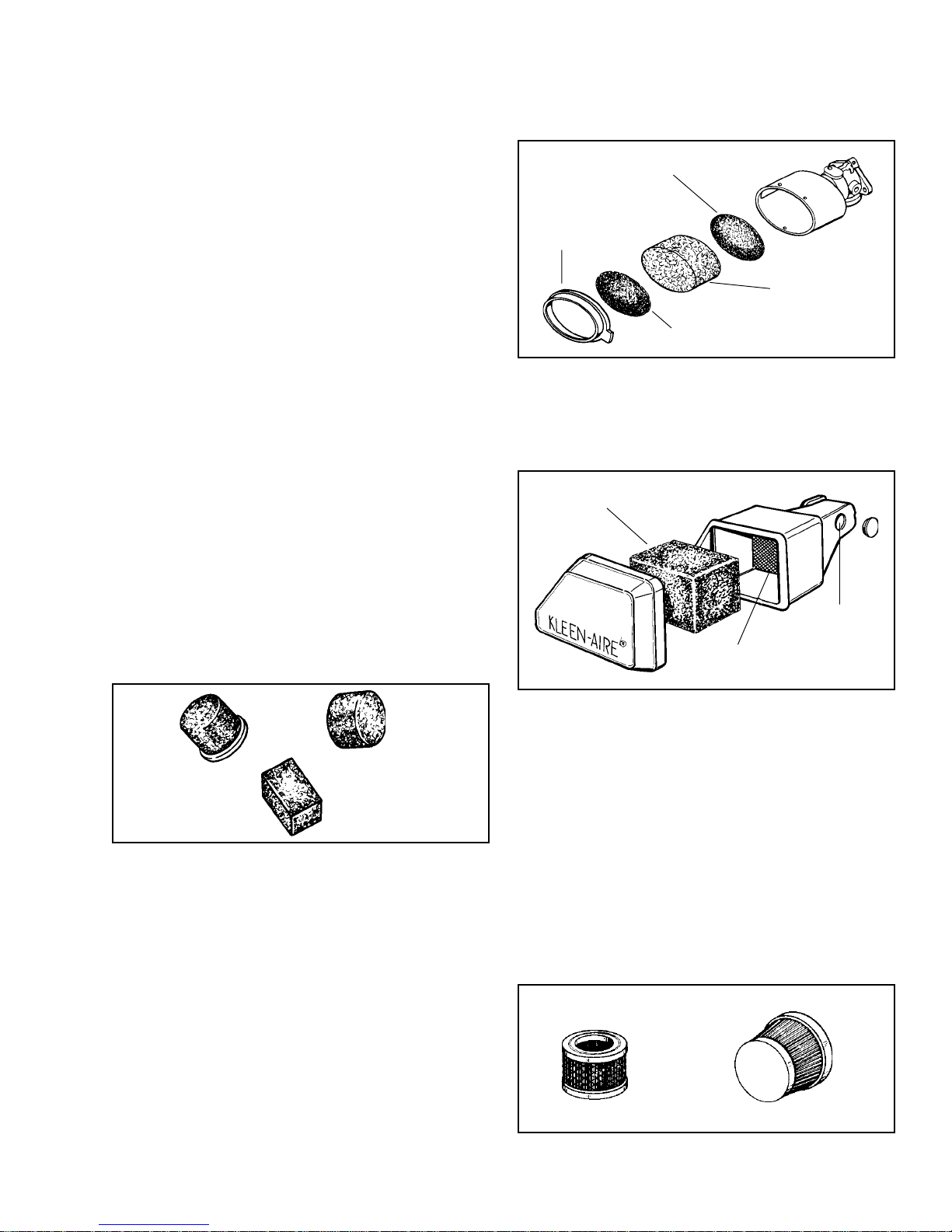
POLYURETHANE-TYPE AIR CLEANER. These
serviceable air cleaners utilize a polyurethane element
which will clog up with use. The element should be
cleaned and serviced in the following manner.
Wash element in a detergent and water solution and
squeeze (dont twist) until all dirt is removed. Rinse
thoroughly.
Wrap in clean cloth and squeeze (dont twist) until
completely dry.
CUPPED SCREEN MUST BE
POSITIONED WITH EDGES AWAY
FROM ELEMENT
COVER
POLYURETHANE
ELEMENT
FLOCKED
SCREEN
KLEEN-AIRE® SYSTEM. This system uses a
polyurethane type element. Service as described under
polyurethane-type air cleaner. When removing air
cleaner body from carburetor, remove plug in the body
to gain access to the mounting screw. Make certain
plug is put back in place. If it shows damage, replace.
POLYURETHANE
ELEMENT
Clean air cleaner housing and cover. Dry thoroughly.
Re-oil element by applying generous quantity of oil to
all sides. Squeeze vigorously to distribute oil and to
remove excess oil. (S.A.E. 30)
When reassembling polyurethane oval type air cleaners,
place cupped screen into housing with edge against
carburetor end of housing. Screen should be installed
to hold element away from housing to allow full utilization
of air cleaner element.
NOTE: Polyurethane type filters will lose effectiveness
if stored for extended periods of time, due to oil migration
(settling Down) through the filter. Re-oil filter as
necessary.
PLUG MUST BE
IN PLACE
FLOCKED
SCREEN
PAPER-TYPE AIR CLEANER SERVICE. Replace air
filter once a year or more often in extremely dusty or
dirty conditions.
DO NOT ATTEMPT TO CLEAN OR OIL PAPER-TYPE
FILTER.
Be sure to clean base and cover thoroughly before
installing new paper filter.
NEVER RUN THE ENGINE WITHOUT THE COMPLETE
AIR CLEANER INSTALLED ON THE ENGINE.
NOTE: Serious damage to the engine may result in
using any other but the specified part number filter.
Use factory recommended parts only.
5
Page 9
GENERAL CARBURETOR INFORMATION
CARBURETOR IDENTIFICATION. Tecumseh carburetors
are identified by a manufacturing number and code
date stamped on the carburetor as illustrated.
ALTERNATE LOCATION
FOR MANUFACTURING NUMBER
89 4 F5
89 4 F 5
CARBURETOR
MANUFACTURING NUMBER
CARBURETOR
CODE DATE
When servicing carburetors, you may use either the
engine model specification number or the manufacturing
number on the carburetor to properly identify. Information
regarding replacement parts or kits are available in
the master parts manual, microfiche catalog or electronic
parts look-up systems.
Tecumseh uses two basic types of carburetors for
their 2 cycle engines, float-type and diaphragm.
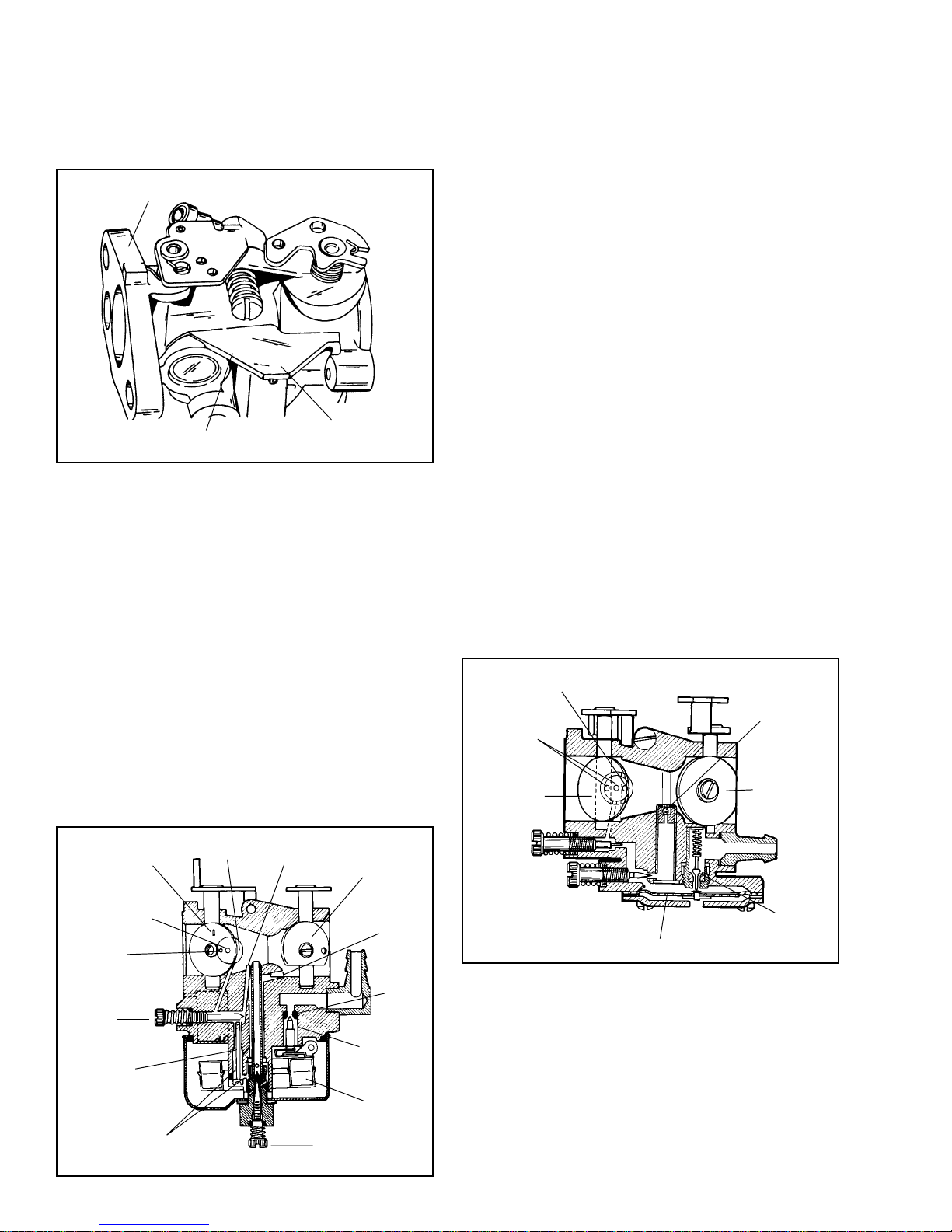
FLOAT-TYPE CARBURETORS. Float-type carburetors
use a hollow metal float to maintain the operating
level of fuel in the carburetor. As the fuel is used, the
fuel level in the carburetor bowl drops and the float
moves downward. This actuates the inlet needle valve,
to allow fuel to flow into the fuel bowl. As the fuel
level in the bowl again rises, so will the float. This
float action adjusts the fuel flow and keeps the fuel
at the proper mixture level. Some carburetors are of
the fixed main type. On these models, the main adjusting
screw and nut are replaced by a fixed main jet bowl
nut.
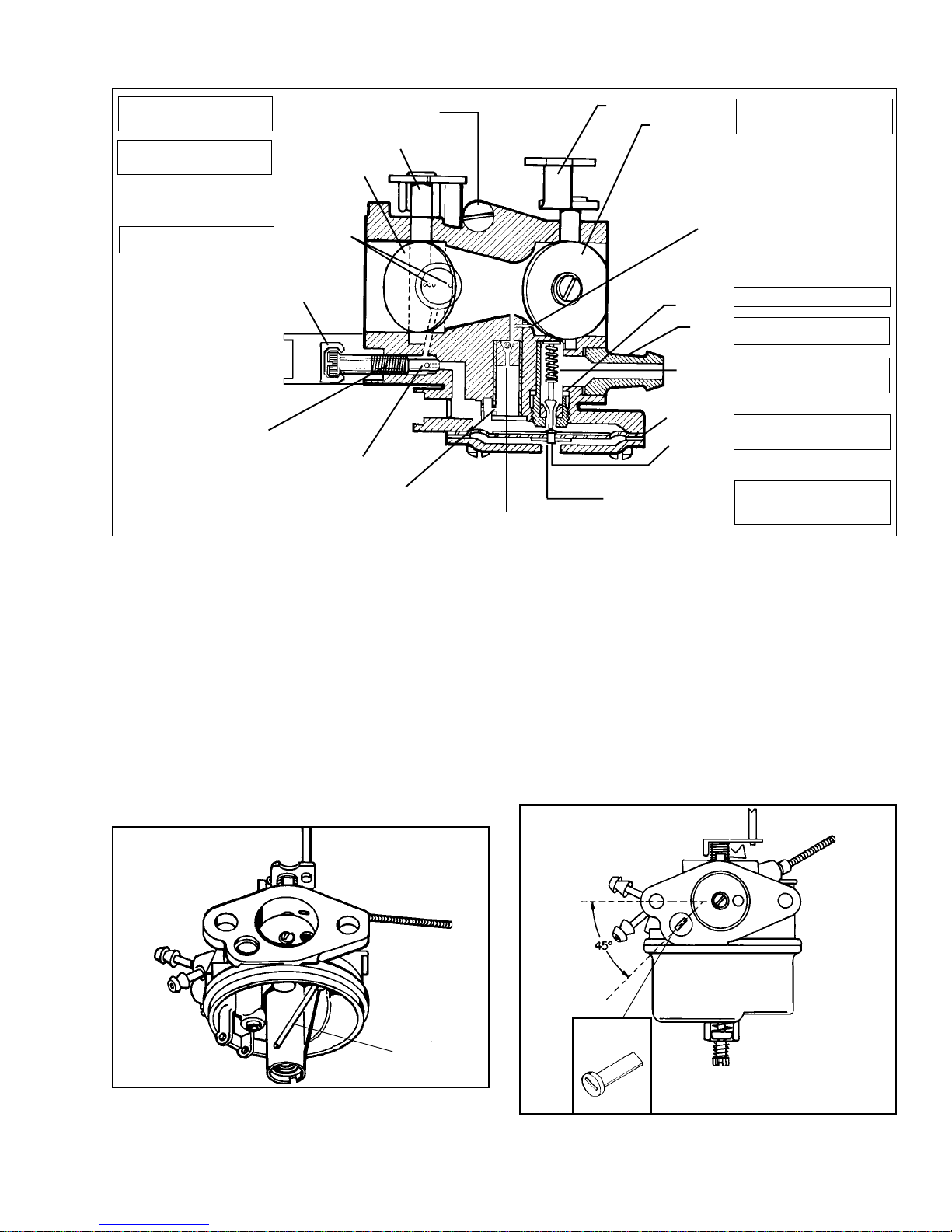
THROTTLE
SHUTTER
SECONDARY IDLE
DISCHARGE
PRIMARY
IDLE DISCHARGE
*IDLE
ADJUSTMENT
SCREW
IDLE FUEL
TRANSFER
PASSAGE
REDUCTION ROD
IDLE FUEL
TRANSFER PASSAGE
*Both jets may be fixed - non adjustable
IDLE FUEL
CHAMBER
IDLE AIR
BLEED
*MAIN ADJUST
CHOKE
SHUTTER
AIR
BLEED
INLET
SEAT
INLET
NEEDLE
FLOAT
DIAPHRAGM (PRESSURE DIFFERENTIAL)
CARBURETORS
This type of carburetor uses a rubber-like diaphragm
which is exposed to intake manifold pressure on one
side and to atmospheric pressure on the other. Tecumseh
diaphragm carburetors use the diaphragm as a metering
device. As the intake manifold pressure decreases
due to downward piston travel, the atmospheric pressure
on the vented side of the diaphragm moves the
diaphragm against the inlet needle. The diaphragm
movement overcomes the spring tension on the inlet
needle and moves the inlet needle off the seat. This
permits the fuel to flow through the inlet valve to maintain
the correct fuel volume in the fuel chamber. The inlet
needle return spring closes the inlet valve when the
pressure on the diaphragm equalizes or a pressure
higher than atmospheric exists on the intake side
(upward piston travel). The diaphragm meters a correct
fuel volume in the fuel chamber to be delivered to
the mixing passages and discharge ports.
A main or idle adjustment needle may be replaced
by an internally fixed jet on some models.
The main nozzle contains a ball check valve. The
main purpose of this ball check is to eliminate air being
drawn down the main nozzle during idle speeds and
leaning the idle mixture.
An advantage of the diaphragm carburetor over the
float system is that the diaphragm carburetor increases
the angle that the engine may be operated at.
AIR
BLEED
IDLE AND
INTERMEDIATE
PORTS
THROTTLE
SHUTTER
IDLE
ADJUST
MAIN
ADJUST
DIAPHRAGM
CHECK
BALL
CHOKE
SHUTTER
FUEL
INLET
INLET
NEEDLE
AND
SEAT
6
Page 10
OPERATION
In the CHOKE or START position, the choke shutter
is closed, and the only air entering the engine enters
through openings around the shutter. As the engine
starts to rotate the downward piston travel will create
a low air pressure area in the engine cylinder above
the piston. Higher pressure (atmospheric air) rushes
into the engine to fill the created low pressure area.
Since the majority of the air passage is blocked by
the choke shutter, a relatively small quantity of air
enters the carburetor at increased speed. The main
nozzle and both idle fuel discharge ports are supplying
fuel due to the low air pressure in the intake of the
engine. A maximum fuel flow through the carburetor
orifices combined with the reduced quantity of air that
passes through the carburetor, make a very rich fuel
mixture which is needed to start a cold engine.
At engine IDLE speed, a relatively small amount of
fuel is required to operate the engine. The throttle is
almost completely closed. A fuel / air mixture is supplied
through the primary idle-fuel discharge orifice during
idle.
During INTERMEDIATE engine operation, a second
orifice is uncovered as the throttle shutter opens, and
more fuel mixture is allowed to atomize with the air
flowing into the engine.
During HIGH SPEED engine operation, the throttle
shutter is opened. Air flows through the carburetor
at high speed. The venturi, which decreases the size
of the air passage through the carburetor, further
accelerates the air flow. This high speed movement
of the air decreases the air pressure at the main nozzle
opening. Fuel is forced out the main nozzle opening
due the difference in the atmospheric air pressure
on the fuel in the carburetor bowl and the reduced
air pressure at the main nozzle opening.
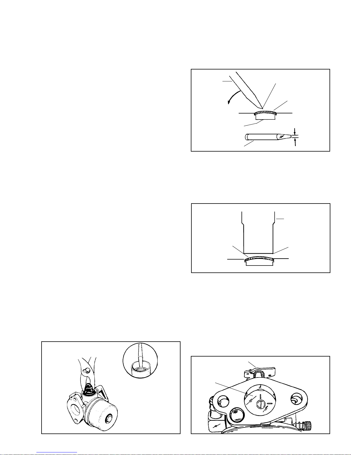
Remove all welch plugs if cleaning the carburetor. Secure
the carburetor in a vise equipped with protective jaws.
Use a small chisel sharpened to a 1/8" wide wedge
point. Drive the chisel into the plug to pierce the metal
and push down on the chisel to pry the plug out of the
hole.
Clean all metallic parts with solvent.
SMALL
CHISEL
PRY OUT
PLUG
DO NOT ALLOW CHISEL
POINT TO STRIKE
CARBURETOR BODY
OR CHANNEL REDUCER
SMALL CHISEL
PIERCE PLUG WITH TIP
WELCH PLUG
TO BE REMOVED
ABOUT 1/8" WIDE
To install a new welch plug after cleaning, place welch
plug into receptacle with raised portion up. With a
punch equal to the size of the plug, merely flatten
the plug. Do not dent or drive the center plug below
the top surface of the carburetor. After installing the
welch plug, seal the outer diameter with finger nail
polish. (Do not use clear polish).
FLAT-END PUNCH
NEW WELCH PLUG
SAME OR LARGER
DIAMETER OF PLUG
CARBURETOR SERVICE. Carefully disassemble
carburetor, removing all non-metallic parts, i.e., gaskets,
viton seats and needles, O rings, fuel pump valves,
etc.
Nylon check balls used in some diaphragm carburetors
are not serviceable. Nylon can be damaged if subjected
to harsh cleaners for prolonged periods.
Remove the primer bulb (if equipped) by grasping with
a pliers and pulling and twisting out of the body. Remove
the retainer by prying and lifting out with a screwdriver.
Do not re-use old bulb or retainer.
THROTTLE. Examine the throttle lever and plate prior
to disassembly. Replace any worn and/or damaged
parts.
When reassembling, it is important that the lines on
the throttle plate are facing out when in the closed
position. Position throttle plates with the two lines at
12 and 3 oclock. If throttle plate has only one line,
the line should be positioned in the 12 oclock position.
If binding occurs, correct by loosening the screws
and repositioning the throttle plate.
THROTTLE LEVER
THROTTLE PLATE
7
Page 11
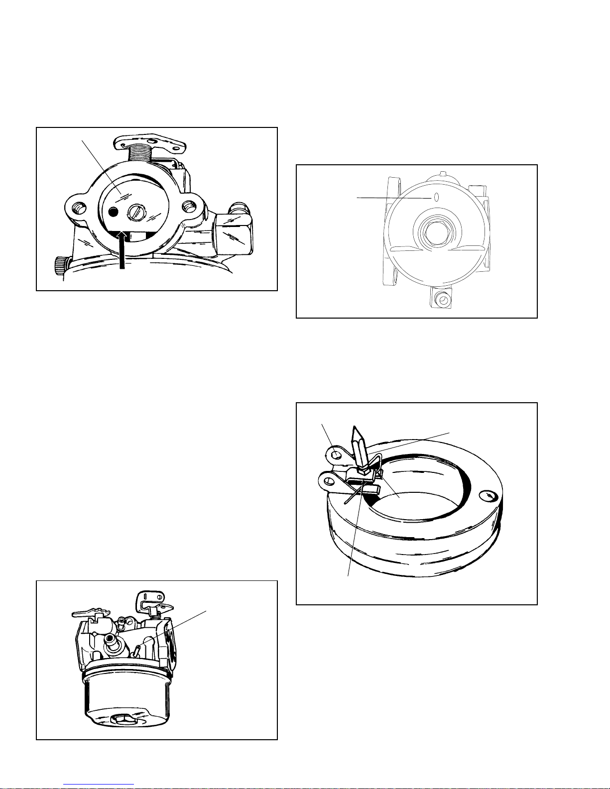
CHOKE. Examine the choke lever and shaft at the
bearing points and holes into which the linkage is
fastened, and replace if worn or damaged. The choke
plate is inserted into the air horn of the carburetor in
such a position, that the flat side of the choke is down.
Before disassembly note the direction of choke plate
movement. Choke plates will operate in either direction.
Make sure it is assembled properly for your engine.
CHOKE PLATE
DOWN TOWARD FUEL BOWL
ADJUSTING SCREWS. Remove the adjusting screws
from the carburetor body and examine the point, replace
the screws if damaged. Tension is maintained on the
screw with a coil spring. Examine and replace the
O ring seal(s) if damaged.
NOTE: If screws are made of plastic, dip the end of
the screw in oil before installation to prevent damage.
FUEL BOWL RETAINING NUT. The fuel bowl retaining
nut has a fixed main jet incorporated in the nut. This
small jet must be clean for proper fuel metering. Clean
by using compressed air. DO NOT USE WIRE OR
HARD OBJECTS FOR CLEANING.
FUEL BOWL. The fuel bowl must be free of dirt and
corrosion. When disassembling a carburetor for repair,
always replace the fuel bowl O ring. Lubricate the
O ring with a small amount of oil for easier installation.
Install the float bowl by placing the detent portion
opposite of the hinge pin. Make sure the deepest end
of the bowl is opposite of the inlet needle. The bowl
has a small dimple located in the deepest part. The
purpose of this dimple is to minimize the chances of
the float sticking to the bottom of the bowl caused by
stale fuel.
DETENT
FLOAT. Remove the float by pulling out the float hinge
pin. Lift the float away from the carburetor body. This
will also lift the inlet needle out of the seat.
Examine the float for damage. Check the float hinge
bearing surfaces for wear, as well as the tab that contacts
the inlet needle. Replace any damaged or worn parts.
EXAMINE FLOAT HINGE FOR WEAR
AT BEARING SURFACES
INLET NEEDLE
CARBURETOR VENTING. Float-type carburetors must
have atmospheric air pressure acting against the fuel
in the fuel bowl. These vents can be external, with a
hole drilled through the side of the carburetor casting
or internal where atmospheric air is picked up in the
air horn near the air cleaner. Regardless of the type,
these vents must be clear and free from dirt, paint,
grease, etc.
HIGH TILT FLOAT STYLE carburetors use an external
main air bleed.
MAIN AIR BLEED
INLET NEEDLE
CLIP
REMOVE FLOAT TO MAKE ADJUSTMENTS.
BEND THIS TAB TO ADJUST
Float sticking can occur due to fuel deposits (gum or
varnish). This can be corrected by loosening the carburetor
bowl nut one full turn and rotating the bowl 1/4 turn in
either direction. Return the bowl to it's original position
and retighten the bowl nut.
8
Page 12
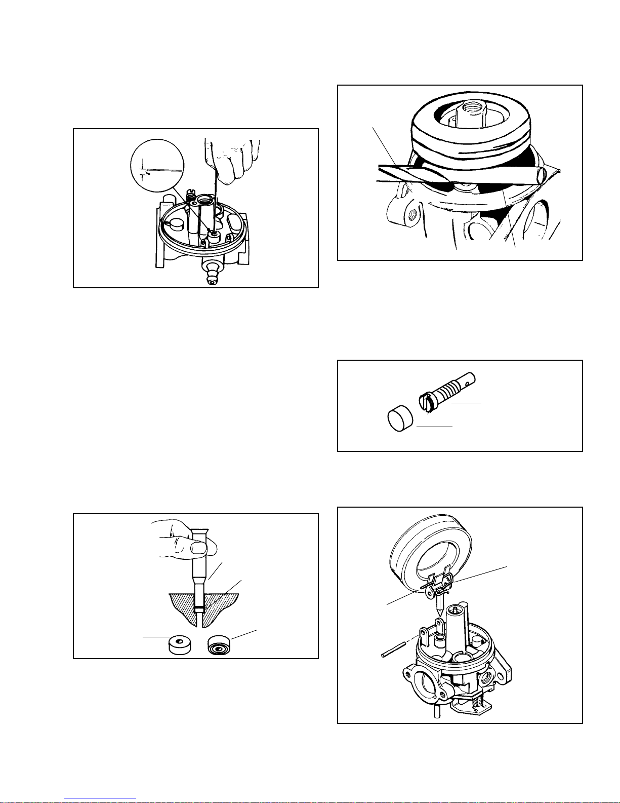
INLET NEEDLE AND SEAT (FLOAT CARBURETORS).
Tecumseh carburetors are built with removable seats
made out of a material called VITON®. These seats
are easily removed by bending the end of a paper
clip or wire with a 3/32" hook or use a #4 crochet
hook. Push the hook through the hole in the center
of the seat and remove it. Never reuse the old seat,
always replace it with a new seat.
3/32"
HOOK END
To install a new seat, make sure the seat cavity is
clean, then moisten the seat with a drop of oil to help
it slide into place. Position the seat with the grooved
side of the seal down and carefully push the seat
into its cavity with a 5/32" flat punch until it bottoms
out.
If the required adjustment is minor, the tab adjustment
may be made without removing float and carefully inserting
a small bladed screwdriver to bend the tab. Be careful
not to damage other parts.
11/64" DRILL BIT
RIM
The idle on the Series 8 is metered using a threaded
restrictor (See illustration). Proper torque of this restrictor
is critical, it should be torqued to 5-8 in. lbs. or .5 to
1 nm, or it may vibrate loose. When the restrictor is
placed in the idle circuit passage it is capped with a
tamper resistant plastic cap. If the jet is removed for
cleaning it must be recapped to prevent tampering
when it is re-installed.
NEEDLE AND SEAT POP-OFF TEST
To test the pop-off pressure, remove the carburetor
from the engine. Be sure to drain any fuel into an
approved container. Invert the carburetor and remove
the float bowl. Place a drop of an oil based product
such as WD-40 on the tip of the needle valve. Using
a commercially available 0-30 psi pump and gauge,
attach the pumps hose to the carburetor inlet. Apply
approximately 6 psi or until the needle pops off the
seat. The needle should seat at 1.5 psi or greater for
a minimum of 5 minutes. If the minimum 1.5 psi cannot
be maintained for this period of time, then service to
the needle and seat is required.
DRIVE IN UNTIL
SEAT RESTS ON
BODY SHOULDER
INLET NEEDLE
SEATS AT THIS
POINT
FLOAT HEIGHT SETTINGS
Previously the float height was set by using a 670253A
float setting tool. The new float setting will require an
11/64" drill bit. The procedure for setting the float height
is as follows. Remove the bowl gasket, then hold the
carburetor in the inverted position. Place the drill bit
across the carburetor body opposite and parallel to
the float hinge pin. Adjust the float height by bending
the tab on the float until it touches the bit.
IDLE RESTRICTOR
CAP
The inlet needle hooks onto the float tab by means of
a spring clip. To prevent binding, the long, straight,
open end of the clip must face the choke end of the
carburetor as shown.
5/32" FLAT PUNCH
CLIP
SEAT
LONG END
OF CLIP
INSERT THIS
FACE FIRST
THROTTLE END
CHOKE END
9
Page 13
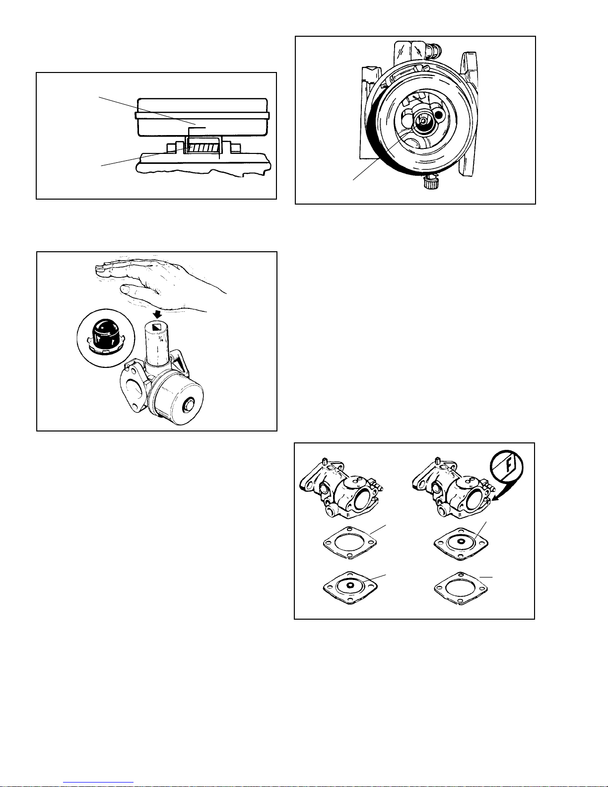
The float dampening spring on the HIGH TILT FLOAT
STYLE carburetor has an extended end which must
point toward the choke end of the carburetor.
POINTS TOWARD
CHOKE END
FLOAT DAMPENING
SPRING
PRIMER BULB. To install, start the retainer and bulb
into the casting with the retainer tabs pointed out. Firmly
push the bulb and retainer into position using a 3/4"
(19mm) deep well socket.
MAIN NOZZLE
DO NOT ATTEMPT TO REMOVE
cleaner and compressed air. With the choke plate and
shaft removed, blow compressed air through the high
speed air bleed located just behind the lower choke
shaft bearing and immediately in front of the venturi
to remove any dirt that may have accumulated.
Blow compressed air through all of the passages, making
sure they are free of dirt, varnish or foreign material.
DIAPHRAGMS. Inspect diaphragms for cracks, tears
or brittleness. Replace if necessary. Rivet head on
diaphragm must always face toward the inlet needle
valve.
CLEANING CARBURETOR BODY. When removing
choke and throttle shafts, check shafts and bearings
in carburetor body for wear. Any looseness in these
areas can cause dirt to enter the engine resulting in
premature wear. If dust seals are present, they should
be positioned next to the carburetor body. Install the
dust seal, metal washer, and finally the return spring.
Welch plugs should be removed for proper cleaning
of the carburetor (See welch plug service at the beginning
of this section). When all accessories and shafts have
been removed, soak the carburetor in carburetor cleaner
for a maximum of 30 minutes. Blow out all passages
with compressed air in the opposite direction of normal
fuel flow.
The carburetor body on non-emission carburetors contains
a main nozzle tube pressed into the carburetor body
to a predetermined depth within the venturi of the
carburetor. DO NOT attempt to remove this main nozzle.
Any movement of this nozzle will seriously affect the
metering characteristics of the carburetor. (Emissions
carburetors have a serviceable plastic nozzle.)
If the carburetor has an "F" designation on the casting,
it will identify the installation sequence of the gasket
and diaphragm on the carburetor. "F" designated
carburetors have the diaphragm installed first then the
gasket then the cover. If there is no designation, the
sequence is gasket, diaphragm and cover.
INLET NEEDLE AND SEAT. (Diaphragm Carburetors)
GASKET
RIDGE AND
RIVET HEAD UP
RIDGE AND
RIVET
HEAD UP
GASKET
Clean the well surrounding the main nozzle with carburetor
10
Page 14
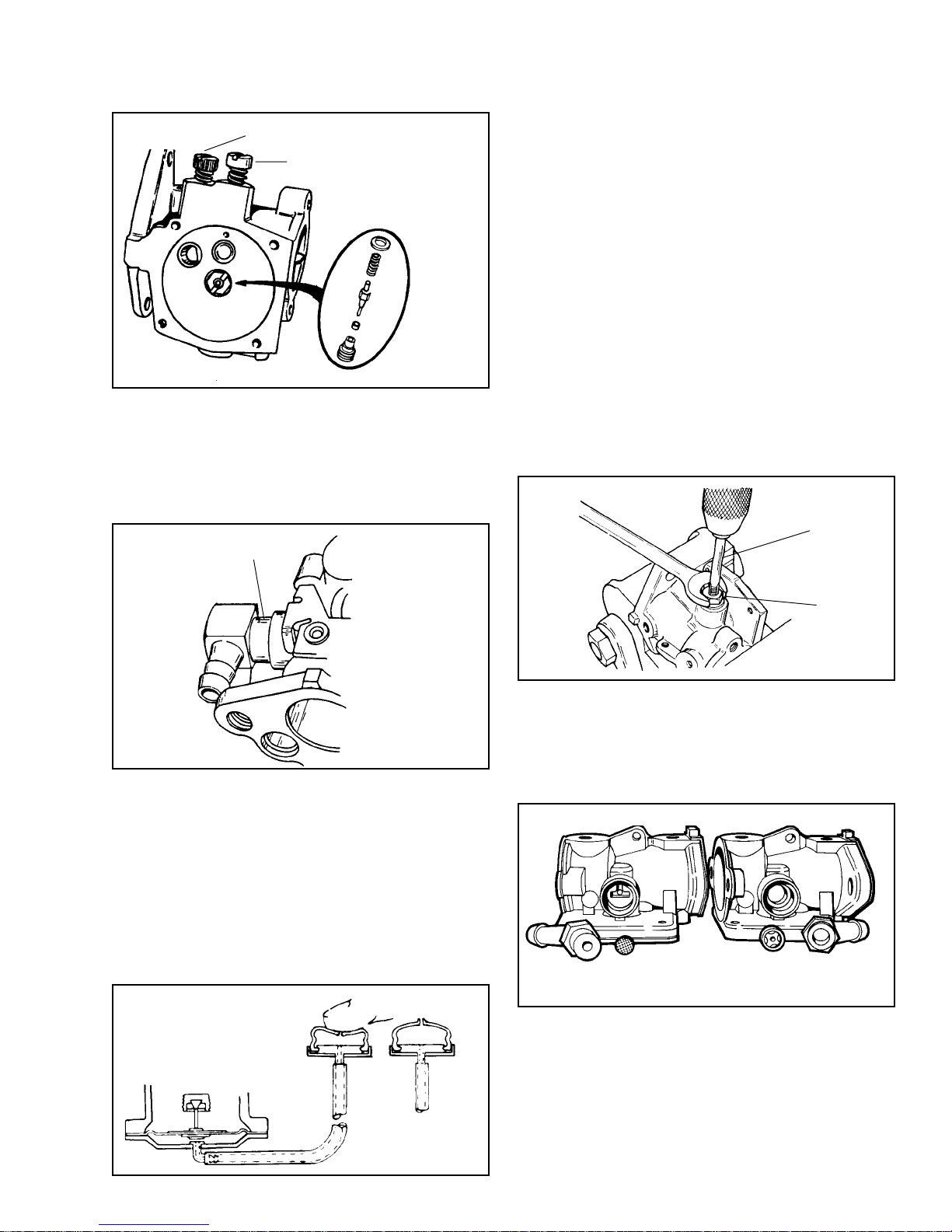
Use a socket to remove inlet needle and seat. Replace
with complete assembly.
FUEL INLET FITTING. If necessary this fitting can
IDLE MIXTURE SCREW
MAIN MIXTURE SCREW
be removed by pulling and twisting. Be sure to install
in the same position as the original. When installing
fitting, insert tip into the carburetor body, then coat
the exposed portion of the shank with Loctite 242 Blue;
then press it in, until the shoulder contacts the carburetor
body.
with primers must have a check valve located in or
behind the fuel inlet fitting of the carburetor. This is
to prevent fuel from being forced back to the fuel line
and tank when priming.
Two types of check valves have been used. One is a
brass check valve pushed into the carburetor body
in the fuel inlet. The other is a teflon disc located in
the area under the fuel fitting. These two types of
check valves are not interchangeable.
To remove the brass type check valve, drill a 9/64'
(3.57 mm) hole through the center of the check valve,
making sure drill does not travel more than 1/8' (3.17
mm) into the body and damage the carburetor.
Turn a nut on to a 8-32 tap and slide a washer on
after it.
Turn the tap with nut and washer into the valve until
the tap begins to protrude through the valve when
viewed through the inlet needle and seat opening.
Turn the nut clockwise to pull the valve out from the
carburetor body.
THE PRIMER BULB (DIAPHRAGM CARBURETOR).
PRESS IN PARTIALLY
THEN APPLY LOCTITE
"242 BLUE"
Pressing the bulb creates air pressure against the
diaphragm. Fully depress primer bulb with your thumb,
making sure that the vent hole in bulb is covered.
Release and allow bulb to return to original position.
As the diaphragm lifts, the inlet needle is lifted off its
seat and the fuel within the reservoir is fed up through
the passages into the air horn. A one-way valve in the
body prevents the fuel from being forced back into
the fuel tank.
CARBURETOR CHECK VALVE. Diaphragm carburetors
PUSH
RELEASE
8-32 TAP
WASHER
The teflon disc-type can be cleaned by using low air
pressure forced into the inlet fitting. If service is required,
pull out inlet fuel fitting and replace the teflon disc.
Put a drop of oil on the disc and position in the cavity
of the carburetor. Replace fuel inlet fitting as outlined
in Fuel Inlet Fitting instructions.
TEFLON
BRASS
11
Page 15
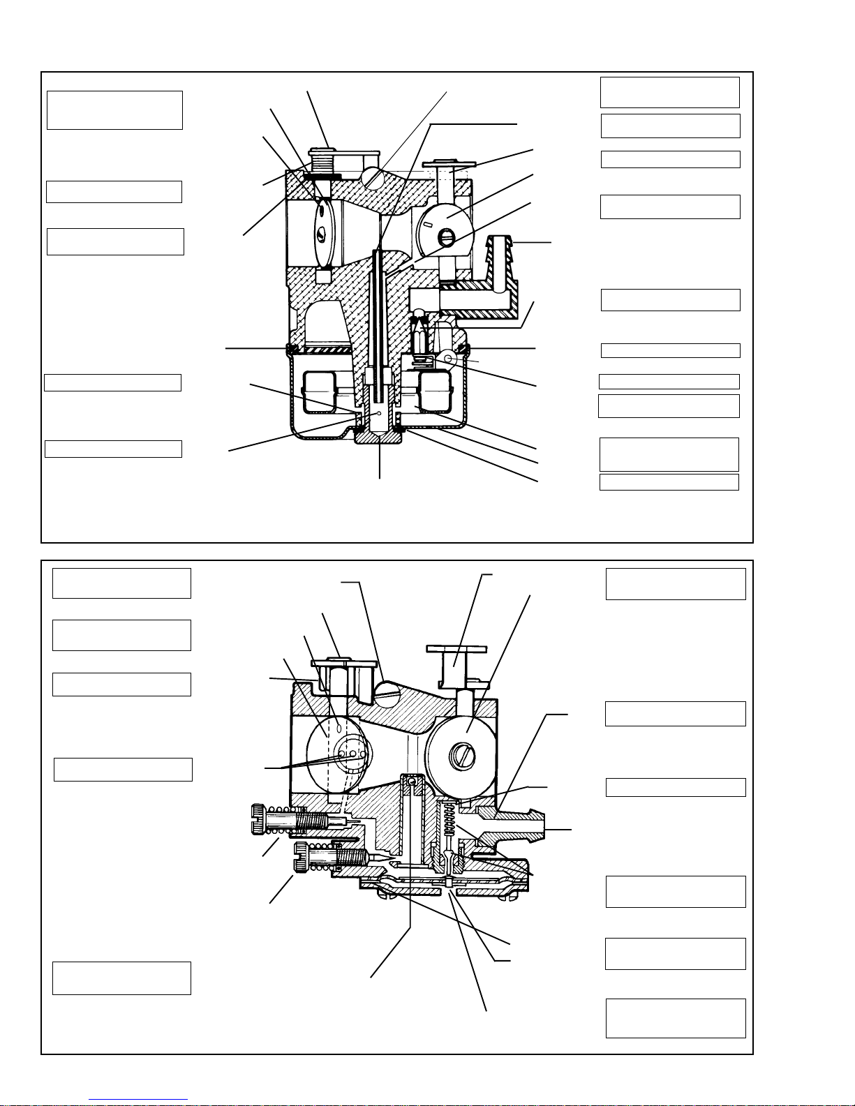
CARBURETOR SERVICE PROCEDURE
Check shaft for looseness or binding.
Shutter must be positioned with
detent reference marks on top
parallel with shaft.
Check spring for return action
and binding.
Remove when cleaning and replace
with new seals.
SOFT BAFFLE PLUG
Clean with compressed air.
Clean with compressed air.
THROTTLE SHAFT AND LEVER
THROTTLE SHUTTER
DETENT
REFERENCE MARK
THROTTLE SHAFT
RETURN SPRING
DUST SEALS
FUEL PICK UP
MAIN JET
BOWL NUT
IDLE SPEED ADJUSTMENT SCREW
MAIN NOZZLE
CHOKE SHAFT
AND LEVER
CHOKE PLATE
MAIN NOZZLE
AIR BLEED
INLET FITTING
*INLET NEEDLE
AND SEAT
*FLOAT BOWL
FLOAT SHAFT
GASKET
INLET
NEEDLE CLIP
FLOAT
FLOAT BOWL
*GASKET
Loosen screw until it just clears
throttle lever, then turn screw in 1
turn.
Do not attempt to remove. Blow air
through passage.
Check shaft for binding.
Blow air through passage. Do not remove restrictor if present.
Proper installation is important. See
appropriate chapter for procedures.
Replace.
Must hook over float tab.
Long straight end of clip must face
the choke end of the carburetor.
Check float for leaks or dents. Clean
bowl and adjust float level position
gasket or gaskets.
Set float to proper level.
*NON METALLIC ITEMS - CAN BE DAMAGED
BY HARSH CARBURETOR CLEANERS
Loosen screw until it just clears
throttle lever, then turn screw in 1
turn.
Place detent reference mark to
proper location. See chapter
appropriate to specific carburetor.
Check spring for return action and
binding.
Remove welch plug and blow air
through air passages.
IDLE SPEED ADJUSTMENT SCREW
THROTTLE SHAFT AND LEVER
DETENT REFERENCE MARK
ON THROTTLE SHUTTER
THROTTLE SHUTTER
THROTTLE SHAFT
RETURN SPRING
IDLE,
INTERMEDIATE
AND AIR BLEED
ORIFICES
*IDLE MIXTURE
ADJUSTMENT
SCREW AND "O"
RING (If Present)
*MAIN MIXTURE
ADJUSTMENT
SCREW AND "O"
RING (If Present)
CHOKE SHAFT AND LEVER
CHOKE SHUTTER
*INLET
FITTING
*INLET SEAT
GASKET
FUEL
*INLET NEEDLE
SEAT AND
SPRING
ASSEMBLY
Check shaft for binding. Position
shutter opening towards inlet fitting
side of air horn.
Primer bulb models have a Teflon
one way valve, in or behind the fitting.
Remove and replace.
Proper installation of assembly is
important. See appropriate chapter
for procedures.
The check ball is a non serviceable
item. Clean with carburetor spra y and
low air pressure only.
*NON METALLIC ITEMS - CAN BE DAMAGED
BY HARSH CARBURETOR CLEANERS
*MAIN NOZZLE WITH CHECK BALL
12
*DIAPHRAGM GASKET
*DIAPHRAGM
ATMOSPHERIC VENT HOLE
Gasket and diaphragm sequence
may be reversed on some models.
Head of rivet must touch inlet needle.
Hole must be clean. On models with
primer bulb, vent hole is very small
and is located off center or in the
primer bulb.
Page 16
EMISSIONIZED DIAPHRAGM CARBURETION
Loosen screw until it just clears
throttle lever, then turn screw in 1
turn.
Place detent reference mark to
proper location. See chapter
appropriate to specific carburetor.
Remove welch plug and blow air
through air passages.
TAMPER RESISTANT CAP
(Pierce to Remove)
BLUE THREAD
LOCK SEALANT
APPLIED
IDLE SPEED ADJUSTMENT SCREW
THROTTLE SHAFT LEVER AND
RETURN SPRING
THROTTLE SHUTTER
IDLE,
INTERMEDIATE
AND AIR BLEED
ORIFICES
FIXED IDLE
RESTRICTER JET
FIXED MAIN JET
MAIN NOZZLE
WITH CHECK BALL
CHOKE SHAFT AND LEVER
CHOKE SHUTTER
HIGH SPEED AIR BLEED
*INLET SEAT
GASKET
*INLET
FITTING
*INLET
NEEDLE
SEAT AND
SPRING
ASSEMBLY
*DIAPHRAGM
GASKET
*DIAPHRAGM
ATMOSPHERIC VENT HOLE
Check shaft for binding. Position
shutter opening towards inlet fitting
side of air horn.
Remove and replace.
Primer bulb models have a Teflon
one way valve, in or behind the fitting.
Proper installation of assembly is
important. See appropriate chapter
for procedures.
Gasket and diaphragm sequence
may be reversed on some models.
Head of rivet must touch inlet needle.
Hole must be clean. On models with
primer bulb, vent hole is very small
and is located off center or in the
primer bulb.
OUTBOARD CARBURETORS
Carburetors on outboard applications use float type
which have a separate idle speed fuel pickup tube
pressed into the casting. The idle mixture screw is
located on the top of the carburetor near the engine.
This carburetor has been manufactured with 2 different
types of inlet needle and seats. One has a hard needle
with a synthetic rubber seat, the other has a nonreplaceable brass seat with a synthetic rubber tipped
needle.
IDLE SPEED
FUEL PICKUP
Outboard carburetors have a built-in fuel pump consisting
of a fuel pump element which inflates and deflates
with crankcase pulses which opens and closes two
flap valves in the fuel pump, thereby pumping fuel
from a remote tank to the carburetor float bowl.
When replacing the fuel pump element, install with
the slot opening at a 45o angle as illustrated.
FUEL PUMP
ELEMENT
13
Page 17
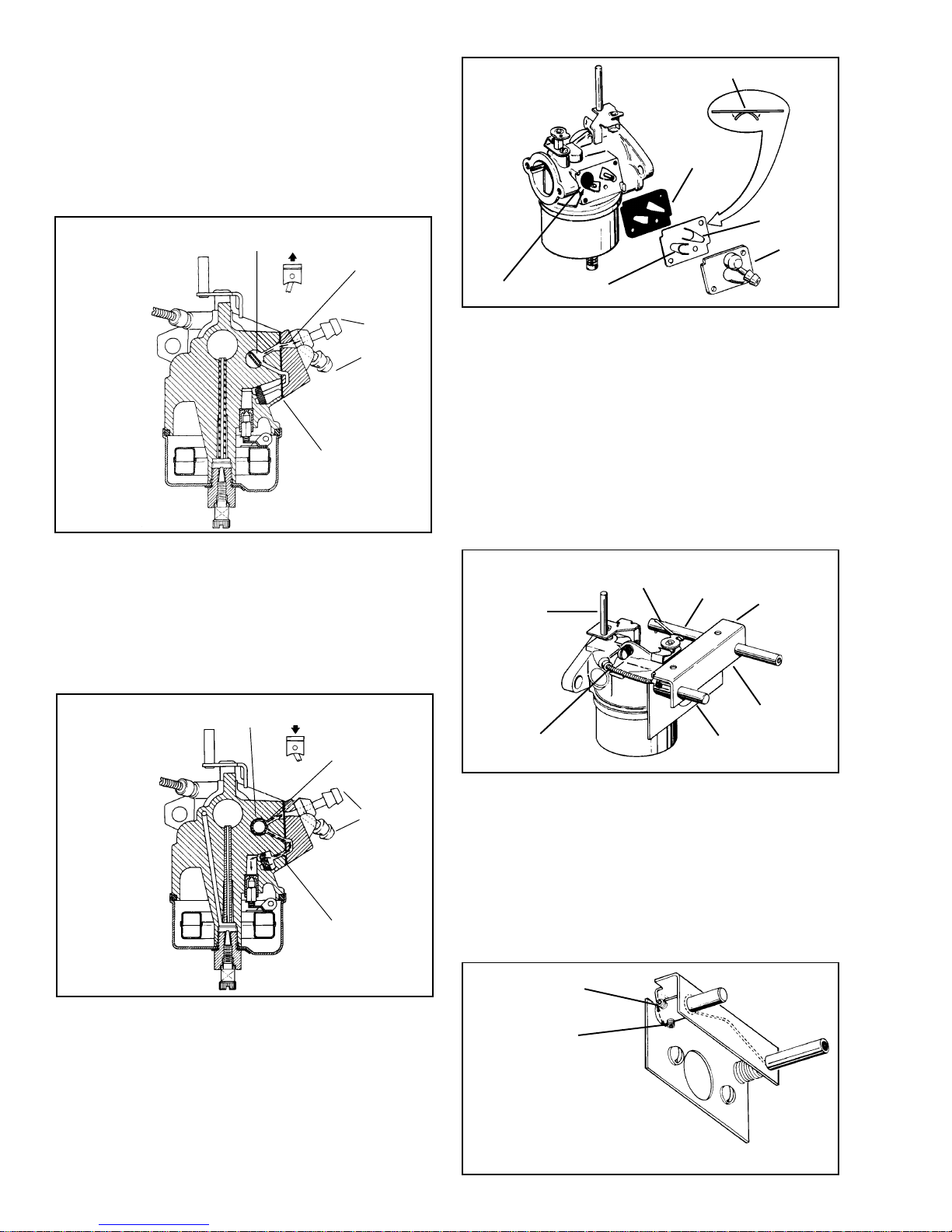
As the engine's piston, moves upward, a partial vacuum
is created in the crankcase, which collapses the fuel
pump element in the carburetor. On the outside of the
element, suction opens the inlet flap drawing a supply
of fuel from the tank and lines into the cavity created
by the deflating pump element. Suction pulls the outlet
flap closed, sealing the outlet port so that fuel isnt
pulled from the area of the inlet needle and seat.
IF CURLED OR FRAYED REPLACE
GASKET
On the downward stroke of the piston, crankcase pressure
FUEL PUMP
ELEMENT DEFLATED
INLET FLAP
VALV E
FUEL
INLET
OUTLET
FLAP
VALV E
enlarges the pump element forcing fuel out of its cavity.
This pressurized fuel acts against the outlet flap valve,
opening it, allowing a head of pressurized fuel to be
transmitted to the inlet needle and seat port. The inlet
valve is pressed against the inlet port, sealing it so
that pressurized fuel does not escape back into the
fuel tank and lines.
INLET FLAP
COVER
STRAINER
OUTLET FLAP
into the rod a complete 2 turns.
Then position the extended end of the choke rod spring
on the idle adjustment rod and align the spring with
the choke rod holes in the bracket. Press the choke
rod through the bracket and spring with the link attaching
hole toward the carburetor side.
Install the choke shaft link in the rod, then install the
other end in the choke lever.
Install the control bracket to the carburetor, but do
not tighten screw completely.
Tighten the setscrew to secure the rod to the idle
LINK
THROTTLE
LEVER POST
CHOKE ROD
ROD STOP
SPRING
The flap valves are located between the cover and
FUEL PUMP
ELEMENT INFLATED
OUTLET
FLAP
VALVE
gasket. Make sure the flaps are in good condition and
the strainer is not clogged or damaged. Replace as
necessary. Make sure the cover is not warped; check
by laying on a flat surface. If warped, replace. If not
warped severely, it can be refaced using a hard surface
and emery cloth. Notches on the carburetor body insure
that the gasket, valve, and cover are positioned on
the body correctly. When tightening screws, snug bottom
screw, then top screw and torque to 6-8 in. lbs.
OUTBOARD CONTROL PANEL. Install the idle
adjustment rod into the bracket then turn the setscrew
14
INLET FLAP
VALV E
FUEL
INLET
IDLE
ADJUST
NEEDLE
AND SPRING
IDLE ADJUST ROD
BRACKET
adjustment cable. The rod should turn about a half
turn before contacting the extended end of the choke
spring.
It is important that the idle adjustment screw be one
full turn from closed, and that the rod setscrew be
down (6 o'clock position) when connecting the rod and
coil.
Tighten the control bracket screw. Pull the choke rod
to assure that the choke shutter closes.
ABOUT 1/2 TURN
6 O'CLOCK
POSITION
FROM THE 6 O'CLOCK POSITION,
THE ROD WILL TURN ABOUT 1/2 TURN
EACH WAY BEFORE BEING STOPPED
BY THE SPRING ROD
Page 18
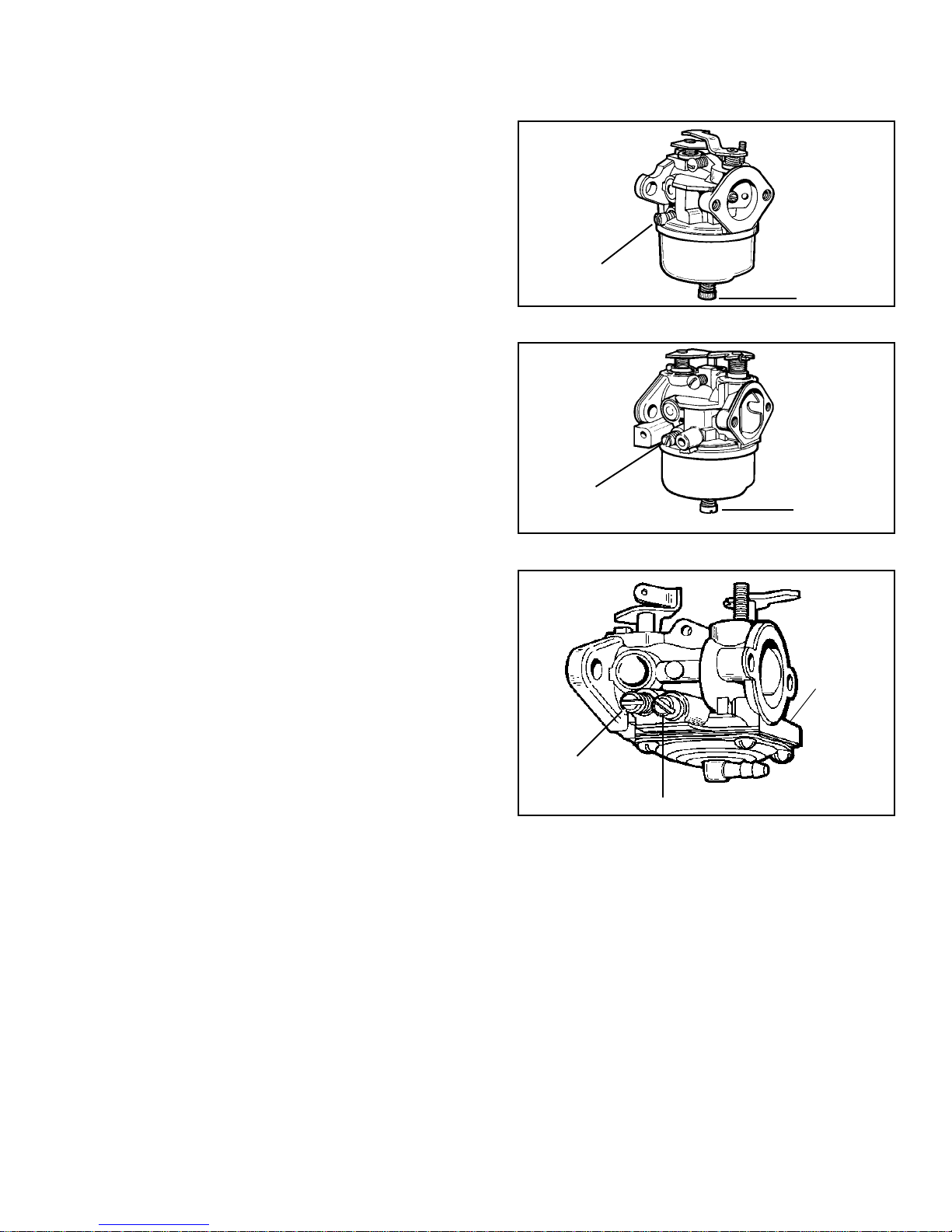
CARBURETOR ADJUSTMENTS
Emission grade carburetors will have fixed main and
idle circuits. The absence of adjustment screws indicate
fixed jets with no adjustments necessary.
CARBURETOR ADJUSTMENTS
IDLE SPEED ADJUSTMENT
This screw is located on top of the carburetor and
contacts the throttle. To pre-set the idle speed, back
out the screw, then turn in until the screw just touches
the throttle lever. Finally, turn the screw in one (1)
turn. Once the engine is running and brought up to
operating temperature (3-5 minutes), the final idle R.P.M.
can be adjusted with the aid of a tachometer.
IDLE MIXTURE
SCREW
SERIES I
MAIN MIXTURE
SCREW
FLOAT TYPE-FIXED MAIN, IDLE ADJUST
Turn the mixture adjusting screw in (clockwise) finger
tight, then one (1) turn out (counterclockwise). This
setting is approximate and will be enough to allow
the engine to start so that final carburetor adjustments
can be made. Start the engine and allow it to warmup for approximately 5 minutes. Do not adjust the
carburetor with the engine cold.
NOTE: If the engine falters or stops after the choke
lever is moved to the "OFF" position, open the mixture
adjusting screw 1/4 turn counterclockwise and restart
the engine.
With the engine running, place the speed control in
the "slow" position. Turn the mixture adjusting screw
clockwise until the engine starts to falter, remember
this location. Next turn the screw counterclockwise
until the engine start to sputter or drops in R.P.M.,
remember this location. Now turn the screw clockwise
until it is halfway between these two locations. This
will be the optimum carburetor setting.
DIAPHRAGM - SINGLE AND DUAL ADJUSTMENT
Turn the mixture adjustment screw(s) clockwise finger
tight, then one (1) turn counterclockwise. This setting
will allow the engine to be started so that the carburetor
can be fine tuned. Do not adjust the carburetor when
the engine is cold.
IDLE MIXTURE
SCREW
IDLE MIXTURE
SCREW
SERIES III, IV
MAIN MIXTURE
SCREW
DIAPHRAGM
"F"
DESIGNATION
F-3
MAIN MIXTURE SCREW
Start the engine and let it warm-up for approximately
5 minutes. If the engine falters or stops after the choke
lever is moved to the "OFF" position, turn the adjusting
screw 1/4 turn counterclockwise and restart the engine.
NOTE: On dual adjust, the first adjustment must be
made with the main mixture screw.
With the engine running, turn the mixture adjustment
screw clockwise until the engine starts to falter,
remember this location. Next turn the screw
counterclockwise until the engine starts to sputter or
drop in R.P.M., remember this location. Now turn the
screw clockwise until it is halfway between these two
locations. This will be the optimum carburetor setting.
With dual adjust carburetor, repeat the above steps
for the second (idle) mixture adjusting screw.
15
Page 19

TROUBLESHOOTING CARBURETION
POINTS TO CHECK FOR CARBURETOR MALFUNCTION
TROUBLE CORRECTIONS
Carburetor out of adjustment ............................... 3-4-11-12-13-15-20
Engine will not start ............................................. 1-2-3-4-5-6-8-9-10-11-12-14-15-16-17-19-21-24-25
Engine will not accelerate ................................... 2-3-4-5-11-12-19-24
Engine hunts (at idle or high speed).................. 3-4-8-9-10-11-12-14-20-21-24-26-27
Engine will not idle ............................................... 3-4-8-9-10-11-12-13-14-18-20-21-22-24-25-26-27
Engine lacks power at high speed ..................... 2-3-4-6-8-10-11-12-15-18-19-20-21-24-25-26
Carburetor floods ................................................. 4-7-17-21-22-25-26
Carburetor leaks .................................................. 4-6-7-10-17-18-23-24-25
Engine overspeeds .............................................. 8-9-11-14-15-18-20
Idle speed is excessive ....................................... 8-9-13-14-15-18-20-25-26-27
Choke does not open fully .................................. 8-9-14-15
Engine starves for fuel at high speed (leans out) 1-3-4-5-6-10-11-15-16-17-18-19-21-25-26
Carburetor runs rich with main adjustment ......... 7-8-9-11-14-17-18-19-21-25-26
needle shut off
Performance unsatisfactory after being serviced1-2-3-4-5-6-7-8-9-10-11-12-14-15-16-17-18-19-20-
21-24-25-26
1. Open fuel shut off valve at fuel tank. Fill tank
with fresh clean fuel.
2. Check ignition, spark plug and compression.
3. Clean air cleaner service as required.
4. Dirt or restriction in fuel system clean tank and
fuel strainers, check for kinks or sharp bends.
5. Check for stale fuel or water in fuel. Fill with fresh
fuel/oil mixture of correct ratio.
6. Examine fuel line and pick-up for sealing at fittings.
7. Check and clean atmospheric vent holes.
8. Examine throttle and choke shafts for binding or
excessive play remove all dirt or paint, replace
shaft.
9. Examine throttle and choke return springs for
operation.
10. Examine idle and main mixture adjustment screws
and O rings for cracks or damage.
11. Adjust main mixture adjustment screw. Some models
require finger tight adjustment. Check to see that
it is the correct screw.
12. Adjust idle mixture adjustment screw. Check to
see that it is the correct screw.
13. Adjust idle speed screw.
16. Clean carburetor after removing all non-metallic
parts that are serviceable. Trace all passages.
17. Check inlet needle and seat for condition and
proper installation.
18. Check sealing of welch plugs, cups, plugs and
gaskets.
19. Check fuel pump operation pump element, inner
and outer one way valves.
20. Adjust governor linkage.
FLOAT CARBURETOR CHECKS
21. Adjust float setting.
22. Check float shaft for wear and float for leaks or
dents.
23. Check seal for fuel drain or bowl gasket.
24. Is carburetor operating at excessive angle?
CHECKS FOR DIAPHRAGM
25. Check diaphragm for cracks or distortion and check
nylon check ball for function.
26. Check sequence of gasket and diaphragm for the
particular carburetor being repaired.
27. Check spring tension on idle governor (if present).
14. Check position of choke and throttle plates.
15. Adjust control cable or linkage to assure full choke
and carburetor control.
16
Page 20
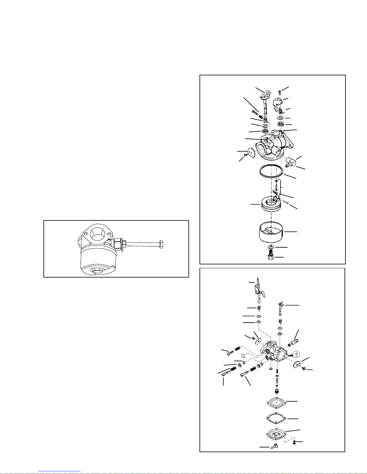
STANDARD SERVICE CARBURETORS
FUEL FITTING
NOTE: MOST service carburetors are marked SVC
CARB NF in the Price List. This means that the carburetor
comes with NO FUEL FITTING.
Use the parts manual to obtain the same fuel inlet
fitting that was installed in the original carburetor. Install
the fuel fitting in the new carburetor body in the same
position as on the original carburetor. Support the
carburetor body with a wood block to avoid damage
to other parts. Use a bench vise or press to install
the fitting squarely. Press it in until it bottoms out.
NOTE: PRESS FUEL FITTING IN SQUARELY USING
CAUTION SO THAT THE CARBURETOR BODY IS
NOT DAMAGED.
INLET FUEL FITTING
To remove a leaking or damaged fuel inlet fitting, use
a 1/4"(6 mm) bolt, 1/4" (6 mm) nut and 1/4" (6 mm)
washer, along with a 1/2" (12 mm) nut. Use a pliers or
vise to remove the plastic part of the inlet fitting. Tap
the inside of the remaining metal portion of the fitting
using a 1/4"- 20 (6 mm) tap. Place a 1/2" (12 mm)
nut over the fuel fitting (it may be necessary to guide
one side of the nut to seat it squarely to the carburetor).
Next thread the 1/4" (6 mm) nut on the bolt until it
contacts the shank, add the washer, and thread the
bolt into the fitting until snug. Tighten the 1/4"-20 (6
mm) nut until the fitting is removed.
IDLE SPEED ADJUSTMENT SCREW
Remove the screw assembly from the original carburetor
and install it in the new carburetor. Turn it in until it
contacts the throttle lever. Then an additional 1 turn
for a static setting.
FLOAT TYPE CARBURETOR
CHOKE SHAFT SELF TAPPING SCREW
IDLE CRACK
SCREW AND
SPRING
SPRING
WASHER
FELT SEAL
CHOKE STOP
SPRING
SHUTTER
SCREW
FLOAT
LEVER
SPRING
WASHER
FELT SEAL
THROTTLE SHAFT
SHANK
FUEL FITTING
"O" RING
SEAT AND CLIP
INLET NEEDLE
SPRING CLIP
FLOAT SHAFT
CHOKE SHAFT
NOTE: Never reuse choke or throttle shutter screws,
always replace with new Tecumseh service screws
part number 650506.
Remove the choke shutter screw from the original
carburetor and remove the choke shaft. Observe the
position of the ends of the choke return spring if one
is present. Also observe the position of the cut-out
and/or holes in choke shutter. Some chokes turn clockwise
and some turn counterclockwise, note the position of
the choke shaft prior to removal from the old carburetor.
If a choke stop spring is present on the new carburetor
and is not used on the old carburetor, cut it off with a
side cutter or pull it out using a pliers.
Test the action of choke shaft to make sure it moves
freely and easily and does not bind in either open or
closed position. If binding occurs, loosen the shutter
screw; reposition the shutter and tighten the screw.
DIAPHRAGM TYPE CARBURETOR
THROTTLE LEVER
AND SHAFT
SPRING
WASHER
FELT SEAL
THROTTLE SHUTTER
SHUTTER SCREW
IDLE ADJUSTMENT
SCREW
SEAL
WASHER
SPRING
LOW SPEED
ADJUSTMENT
SCREW
HIGH SPEED
ADJUSTMENT
SCREW
FLOAT BOWL
BOWL NUT WASHER
HIGH SPEED BOWL NUT
CHOKE LEVER
AND SHAFT
FUEL INLET
CHOKE
SHUTTER
SHUTTER
SCREW
DIAPHRAGM
THROTTLE LEVER
Remove the throttle lever and spring and file off the
peened end of the throttle shaft until the lever can
be removed. Install the throttle spring and lever on
the new carburetor with the self-tapping screw furnished.
If dust seals are furnished, install them under the return
spring.
PRIMER FITTING
DIAPHRAGM
GASKET
DIAPHRAGM
COVER
DIAPHRAGM
COVER SCREW
17
Page 21
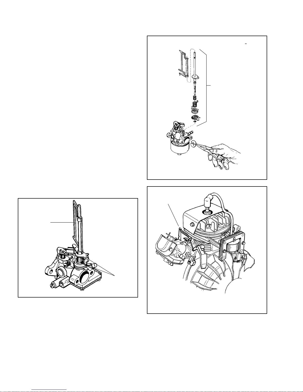
GOVERNORS AND LINKAGE
AIR VANE GOVERNORS. All Tecumseh 2 cycle engines
covered in this book are equipped with pneumatic
(air vane) governors. The governor's function is to
maintain a R.P.M. setting when engine loads are added
or taken away. Air vane governors are controlled by
the air velocity created by fins on the flywheel. Changes
in the engine R.P.M. cause the air vane to move. The
throttle is opened as the engine R.P.M. drops and is
closed as the engine load is removed.
OPERATION
Engine R.P.M. changes cause an increase or decrease
in the air velocity created by the fins on the flywheel.
The air velocity exerts pressure on the air vane while
a governor spring exerts pressure against the air velocity
force. The air vane pivots on the engine flange or is
attached to the throttle shaft of the carburetor. As an
engine load is applied and the engine's R.P.M drop,
the air velocity also drops, allowing the governor spring
to pull open the throttle shaft and increase engine
speed.
LINKAGE INSTALLATION. The best method is to record
the linkage attachment points prior to disassembly
and reinstall the same way.
AIR VANE
ASSEMBLY
Illustrations showing most governor and linkage hookups
are pictured in this section. Select the diagram that
resembles the engine you are servicing. R.P.M. settings
may be found in microfiche catalog, card number 30.
AIR VANE
SLEEVE
TABS
Rotate sleeve clockwise to increase R.P.M.;
counterclockwise to decrease R.P.M.
BEND TAB TO
ADJUST RPM
HORIZONTAL FIXED SPEED
PLASTIC AIR VANE GOVERNOR
NOTE: The sleeve is serrated to rotate in a clockwise
direction and must be raised using the sleeve tabs
before it can be rotated counterclockwise.
To disassemble, remove choke shutter with needlenose pliers; the vane assembly may then be removed
from the carburetor.
18
Page 22
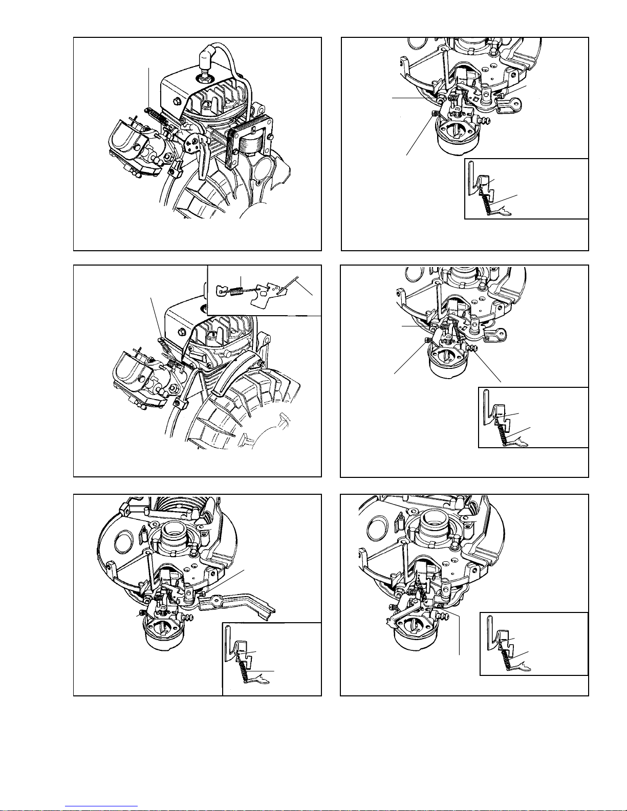
ADJUST RPM BY
LOOSENING SCREW AND
SLIDING BRACKET
Ó INCREASE
È DECREASE
HORIZONTAL FIXED SPEED
(ALUMINUM AIR VANE GOVERNOR)
IDLE RPM
ADJUSTMENT
IDLE
MIXTURE
VARIABLE SPEED-REMOTE CONTROL
HIGH SPEED
RPM
ADJUSTMENT
THIS HOLE NOT
PRESENT ON ALL
MODELS
SPRING
VERTICAL ENGINE
ADJUST RPM BY
LOOSENING SCREW AND
SLIDING BRACKET
Ó INCREASE
È DECREASE
HORIZONTAL FIXED SPEED
SPRING
GOVERNOR
LINK
HIGH SPEED RPM
ADJUSTMENT
IDLE RPM
ADJUSTMENT
IDLE
MIXTURE
THIS HOLE NOT
PRESENT ON ALL
MODELS
VERTICAL ENGINE
FIXED SPEED-REMOTE CONTROL
IDLE RPM
ADJUSTMENTS
VERTICAL ENGINE
VARIABLE SPEED
MANUAL CONTROL
THIS HOLE NOT
PRESENT ON
ALL MODELS
SPRING
THIS HOLE NOT
PRESENT ON ALL
MODELS
SPRING
RPM ADJUSTMENT
VERTICAL ENGINE FIXED SPEED
19
Page 23
REWIND STARTERS, ELECTRIC STARTERS AND
ALTERNATORS
REWIND STARTERS
GENERAL INFORMATION
Rewind starters used on vertical shaft Tecumseh engines
are top mount horizontal pull style or side mount vertical
pull style. Horizontal shaft engines use side mounted
starters which can be mounted to pull either vertically
or horizontally. All rewind starters except the vertical
pull style turn the engine over by engaging a dog(s)
into the starter cup attached to the engine flywheel.
The vertical pull starter engages the starter gear into
the ring gear of the flywheel to turn the engine over.
All starters are spring loaded to retract the dog(s) or
starter gear when the engine speed exceeds the turning
speed of the starter.
OPERATION
As the starter rope is pulled, the starter pulley rotates
on the center pin. The starter dog(s) is pinned or
pocketed in the pulley hub and extends outward when
the pulley's rotation forces the starter dog(s) to contact
the ears on the retainer. The retainer ears act as a
ramp to fully extend the starter dog(s). The fully extended
starter dog(s) locks in contact with notches in the
starter cup. When the engine fires and the rotational
speed of the starter cup exceeds the starter pulley,
the starter dog(s) disengages from the starter cup.
The starter dog spring(s) returns the starter dog(s)
to the disengaged position. The recoil spring turns the
starter pulley in the opposite direction, retracting the
starter rope until the handle contacts the stop.
SERVICE
Starter related problems will require the starter to be
removed from the engine to diagnose the cause. Visually
inspect the starter dog(s), starter cup, retainer, springs,
rope, washers, and the starter pulley for wear or breakage.
Use one of the following procedures that applies to
your application, to disassemble, repair, and assemble
the starter. Always consult the Tecumseh Master Parts
Manual for the correct replacement parts.
ROPE SERVICE
Rope replacement should be done using the correct
part number replacement rope or braided rope of the
correct diameter and length. Consult the Tecumseh
Master Parts Manual to obtain the correct part number,
length, and size required. Use the following rope chart
to convert a numbered rope to a fractional diameter
for bulk rope use.
# 4 1/2 rope = 9/64" (3.572 mm) diameter
Part No. 730526 -100' (30.48 meters)
spool
# 5 rope = 5/32" (3.964 mm) diameter
Part No. 730514 - 100' (30.48 meters)
spool
# 6 rope = 3/16" (4.762 mm) diameter
Part No. 730516 - 100' (30.48 meters)
spool
Standard rope lengths
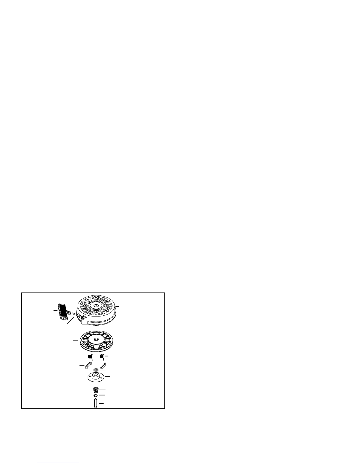
COMPONENTS
HANDLE
ROPE
PULLEY AND REWIND
SPRING ASSY.
STARTER DOG
20
STARTER HOUSING
DOG SPRING
WASHER
RETAINER
BRAKE SPRING
WASHER
SPRING PIN
54" (16.5 meters) standard stamped steel starter
61" (18.6 meters) vertical pull - horizontal engagement
type
65" (20 meters) vertical pull - vertical engagement
type
85" (26 meters) extended handlebar rope start
(compliance)
Check the old rope for the right length for the application.
Some applications require longer lengths. The rope
ends should be cauterized by burning with a match
and wiping the rope end with a cloth while hot.
Rope replacement can be done without the starter being
disassembled on vertical pull starters that have "V"
notches in the bracket. Use the following procedure
for rope replacement.
1. Remove the starter assembly from the engine.
2. Turn the pulley until the staple in the pulley lines
up with the "V" notch. Pry out the staple with a
small screwdriver and remove the original rope.
Page 24
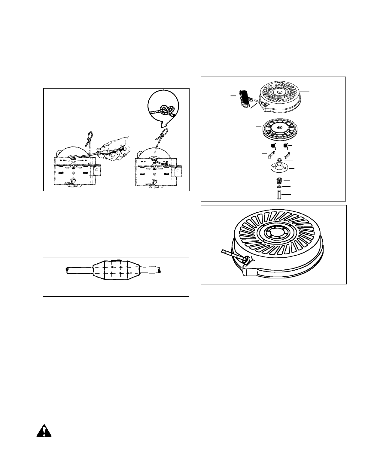
3. Turn the pulley counterclockwise to fully wind the
starter return spring until tight. Allow the pulley
to unwind until the hole in the pulley lines up with
the "V" notch.
4. Hold the pulley in this position and feed the new
rope through the hole and tie a left-handed knot
on the rope end. Make sure the rope and knot do
not protrude from the knot cavity and bind the
pulley rotation.
4. Remove the brake spring, spring retainer, washers,
and pulley assembly (diag. 7, 8, 9 & 10)
NOTE: The starter dogs face out on the stamped
steel starter and the dogs face in on the stylized
rewind starter.
5. All components in need of service should be replaced.
LEFT-HAND
KNOT
RETAINER REPLACEMENT
1. Remove the starter handle if the retainer is a complete
circle design. Remove the staple and old retainer.
2. Slide the rope retainer into the proper position and
insert the staple using a pliers.
3. Install the starter handle and tie a left hand knot
to secure the handle.
HANDLE
ROPE
PULLEY AND REWIND
SPRING ASSY.
STARTER DOG
STARTER
HOUSING
DOG SPRING
WASHER
RETAINER
BRAKE SPRING
WASHER
SPRING PIN
ONE PIECE ROPE RETAINER
STYLIZED REWIND STARTER
Disassembly Procedure
1. After removing the rewind assembly from the engine
blower housing, release the tension on the rewind
spring. This can be done by removing the starter
handle and carefully allowing the rope to unwind in
the starter housing assembly.
2. Place a 1" (25 mm) deep well socket under the
retainer. Set the rewind on a bench, supported
on the socket.
3. Use a 5/16" (7.938 mm) or 1/4" (6.35 mm) (for
stamped steel) roll pin punch to drive out the center
pin. The stamped steel center pin is driven out
from the top, inside the center hole. Move the punch
around while driving the pin to help keep the pin
straight.
CAUTION: THIS REWIND SPRING IS NOT
SECURED IN A CANISTER. PULLEY BOSSES
HOLD THE REWIND SPRING AND COVER, AND
CAN BE EASILY DISLODGED DURING
HANDLING.
21
Page 25
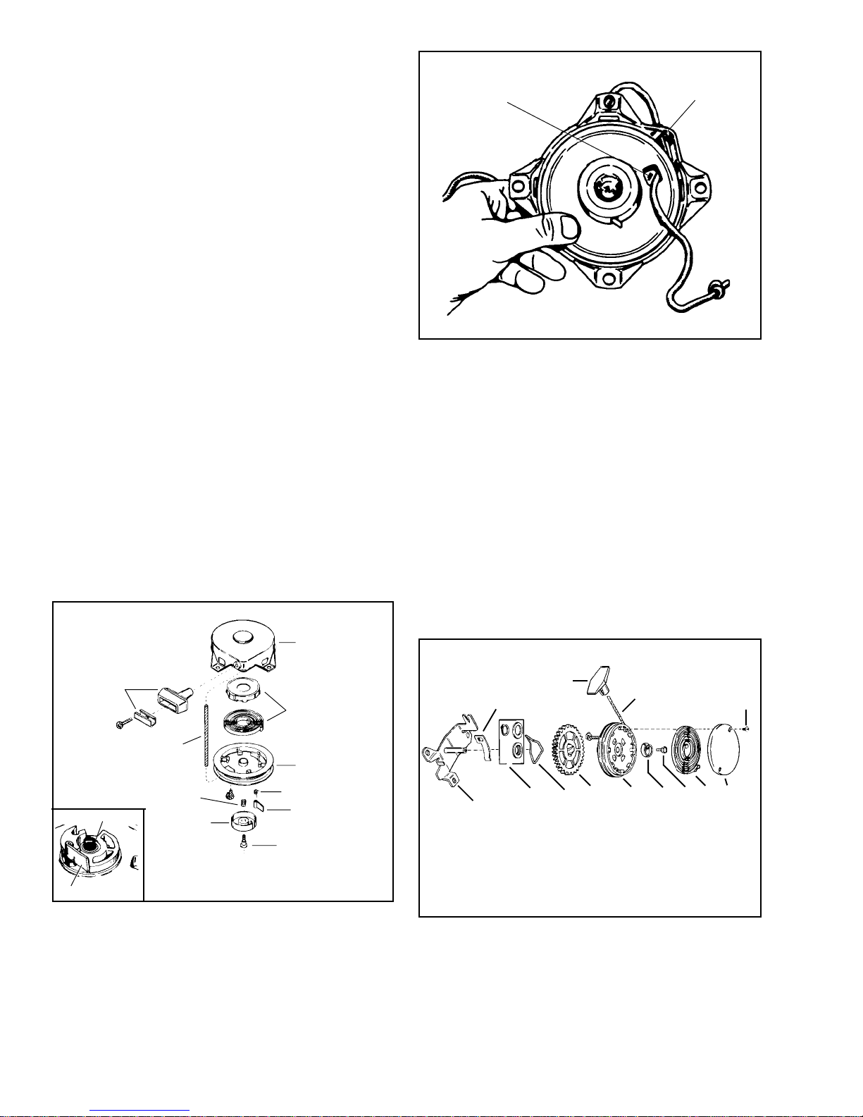
ASSEMBLY PROCEDURE
NOTE: It is critical to support the starter on a deep
well socket to prevent damage.
1. Reverse the disassembly procedure. The starter
dogs with the dog springs must snap back to the
center of the pulley (disengaged position). When
the rope is pulled, the tabs on the retainer must be
positioned so that they will force the starter dogs
to engage the starter cup. (diag. 7 & 8)
2. Always replace the center spring pin with a new
one upon reassembly. Place the two new plastic
washers between the center leg of the starter and
the retainer. New plastic washers are provided with
a new center spring pin. Discard the old plastic
washer.
3. Place the rewind on a flat surface and drive the
new center pin in until it is within 1/8" (3.175 mm)
of the top of the starter.
NOTE: DO NOT DRIVE THE CENTER PIN IN TOO
FAR.
The retainer will bend and the starter dogs will not
engage the starter cup. On the stamped steel starter
the center pin should be driven in until it contacts
the shoulder in the starter body.
4. Wind the starter pulley counterclockwise four or
five turns to pre-load the recoil spring, thread the
rope through the starter housing eyelet and tie a
temporary knot in the rope. Reattach the starter
handle to the rope using a left-hand knot. Untie
the temporary knot and allow the rope to recoil.
HOLE IN PULLEY
EYELET
VERTICAL PULL STARTER HORIZONTAL
ENGAGEMENT TYPE
DISASSEMBLY PROCEDURE
1. Remove the handle and relieve the starter spring
tension by allowing the rope to slip past the rope
clip.
2. Remove the spring cover by carefully removing
the two small screws. Carefully take out the spring.
3. Remove the center hub screw and the spring hub.
4. Lift off the gear and pulley assembly. Disassemble
the pulley assembly by removing the snap ring
and washer (diag. 13).
HANDLE ASSY.
BRAKE SPRING
BRAKE SPRING
STARTER DOG
ROPE
RETAINER
HOUSING
SPRING & KEEPER
ASSY.
PULLEY
DOG SPRING
DOG
RETAINER SCREW
5. Remove the starter rope if necessary. Replace all
worn or damaged parts.
ROPE CLIP
MOUNTING
BRACKET
HANDLE
THRUST WASHER
AND SNAP SCREW
GEAR
BRAKE SPRING
ROPE
SPRING HUB
PULLEY
SCREW
SPRING
SCREW
COVER
22
Page 26
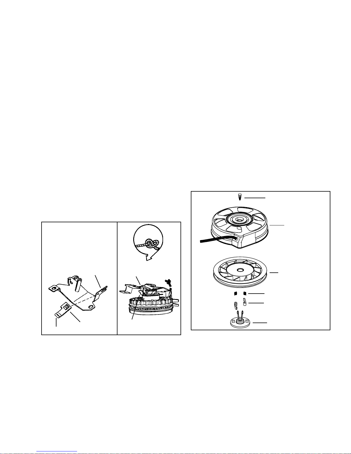
Assembly Procedure
1. Insert the rope through the starter pulley.
2. Assemble the gear, pulley, washer, and snap ring.
3. Place a small amount of grease on the center shaft,
place the gear and pulley into position making sure
the brake spring loop is positioned over the metal
tab on the bracket. The rope clip must fit tightly
onto the bracket. The raised section fits into the
hole in the bracket.
4. Install the hub and hub screw. Torque the hub screw
to 45 - 55 in. lbs. (5 - 6 Nm). A loose hub screw
will prevent the rope from retracting.
5. Install the return spring if necessary. A replacement
spring is installed by placing the spring and its
retainer over the top of the pulley and pushing the
spring out of the retainer into the pulley's recessed
area.
6. Install the spring cover and the cover screws.
7. Wind the rope onto the pulley by slipping it past
the rope clip. When the rope is fully wound on the
pulley, wind the pulley assembly two additional
turns to put tension on the spring.
STYLIZED REWIND STARTER WITH
PLASTIC RETAINER
DISASSEMBLY PROCEDURE
1. After removing the rewind assembly from the engine
blower housing, remove the starter handle by first
pulling a length of rope out using the handle, tying
a temporary knot in the exposed rope, and either
untying the knot in handle or prying out the staple.
2. Untie the temporary knot and slowly allow the rope
to fully retract into the starter housing and the
recoil spring to fully unwind.
3. Remove the decal from the center of the starter
housing.
4. Use a small Phillips screwdriver or similar tool to
pry the retainer legs apart and lift out the retaining
wedge.
5. Pinch the legs of the retainer together and pull
on the head of the retainer to remove it from the
housing.
6. Remove the pulley assembly from the recoil housing.
7. Repair or replace as necessary.
8. Mount the starter on the engine making sure the
top of the starter gear teeth are no closer than
1/16" (1.59 mm) from the top of the flywheel ring
gear teeth.
LEFT-HAND
KNOT
RECEPTACLE
FOR RAISED
SECTION
RAISED SPOT
ROPE CLIP
MOUNTING BRACKET
TAB MUST FIT INTO
SPRING LOOP
BRAKE
RET AINER WEDGE
ST ARTER
HOUSING
ST ARTER PULLEY
SPRING & COVER
DOG SPRING
ST ARTER DOG
DOG RET AINER
ASSEMBLY
1. If replacing the starter rope, see Step 8.
2. Install a new recoil spring if necessary by pushing
the new spring out of the holder into the pulley
cavity while aligning the outside spring hook into
the deep notch in the pulley. Push the spring cover
in until seated.
3. Apply a small amount of lithium grease to the inner
bore of the center shaft.
4. Replace or check that both starter dogs are in the
pulley pockets and that the dog springs are hooked
on the outer surface of the dog.
23
Page 27
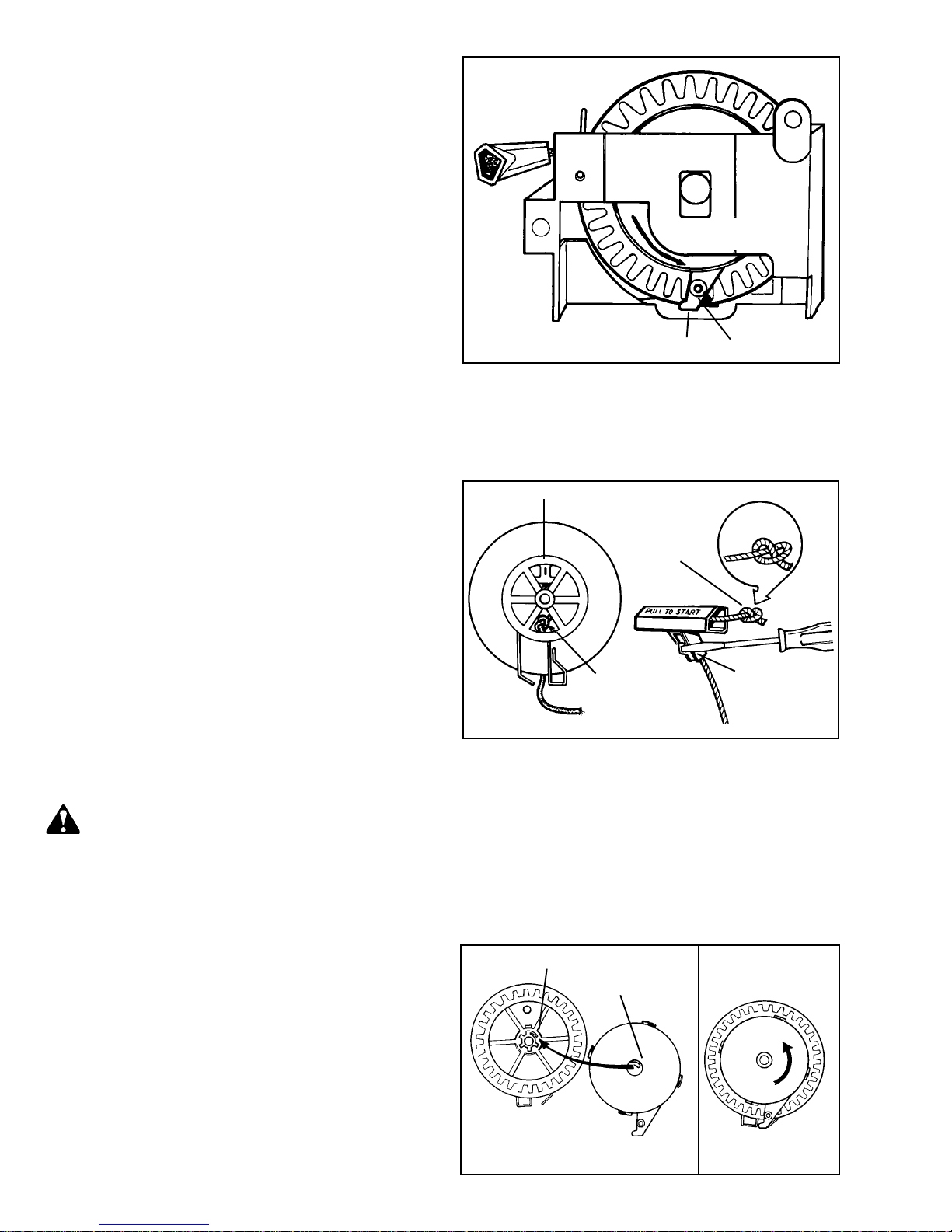
5. Pinch the two legs of the plastic retainer together
and start into the center shaft hole.
6. Rotate the retainer so the two tabs on the bottom
of the part fit between the dog and pulley hub (left
side of the dog). Push the retainer in until the leg
prongs pop out of the center shaft.
7. Turn the starter over and snap the locking tab between
the retainer legs, replace the top decal.
NOTE: Refer to Service Bulletin 122 for metal locking
tab.
8. Wind the starter pulley counterclockwise four or
five turns to pre-load the recoil spring and thread
the rope through the starter housing eyelet. Pull
enough rope through to tie a temporary knot in the
rope. Reattach the starter handle to the rope using
a left-hand knot. Untie the temporary knot and allow
the rope to recoil.
VERTICAL PULL STARTER, VERTICAL
ENGAGEMENT TYPE
ROTATE
COUNTERCLOCKWISE
STRUT
PIN
ASSEMBLY PROCEDURE
1. Feed the new rope through the hole and tie a lefthanded knot on the rope end. Make sure the rope
and knot do not protrude from the knot cavity and
bind the pulley rotation.
DISASSEMBLY PROCEDURE
1. Pull out enough rope to lock the rope in the "V" of
the bracket.
2. Remove the handle if necessary by prying out the
small staple in the handle with a screwdriver.
3. Place the starter bracket on the top of a deep well
socket that is large enough to receive the head of
the center pin. Use an arbor press to drive out the
center pin.
4. Rotate the spring capsule strut until it is aligned
with the legs of the brake spring. Insert a nail or
pin no longer than 3/4" (19.05 mm) through the
hole in the strut so it catches in the gear teeth.
This will keep the capsule in the wound position.
5. Slip the sheave out of the bracket.
CAUTION: DO NOT ATTEMPT TO REMOVE THE
SPRING CAPSULE FROM THE SHEAVE
ASSEMBLY UNLESS THE SPRING IS FULLY
UNWOUND.
6. Squeeze and hold tightly by hand the spring capsule
at the outer edge against the gear sheave.
7. Remove the retainer pin from the strut and slowly
relieve the spring tension by allowing the spring
capsule to rotate slowly under control, until completely
unwound. The spring capsule can now be removed
from the gear sheave.
ORIGINAL INSTALLATION WITH STAPLE
INSTALL NEW
ROPE BY TYING
LEFT-HAND
KNOT
REINSTALL
LEFT-HANDED
KNOT
LEFT-HAND
KNOT
PRY STAPLE
OUT TO
REMOVE OLD
ROPE
2. Wind the rope on the sheave assembly clockwise,
viewing the gear from the gear side of the sheave.
3. Reinstall the brake spring, being careful not to
spread the spring more than necessary.
4. Install the spring capsule, making sure the starter
spring end hooks on the gear hub.
5. Wind the spring four full turns and align the brake
spring legs with the strut as shown. Insert the pin
in the strut.
GEAR HUB
STARTER SPRING
END
24
SPRING HOOKED ON
GEAR HUB
ROTATE SPRING
4 FULL TURNS
Page 28
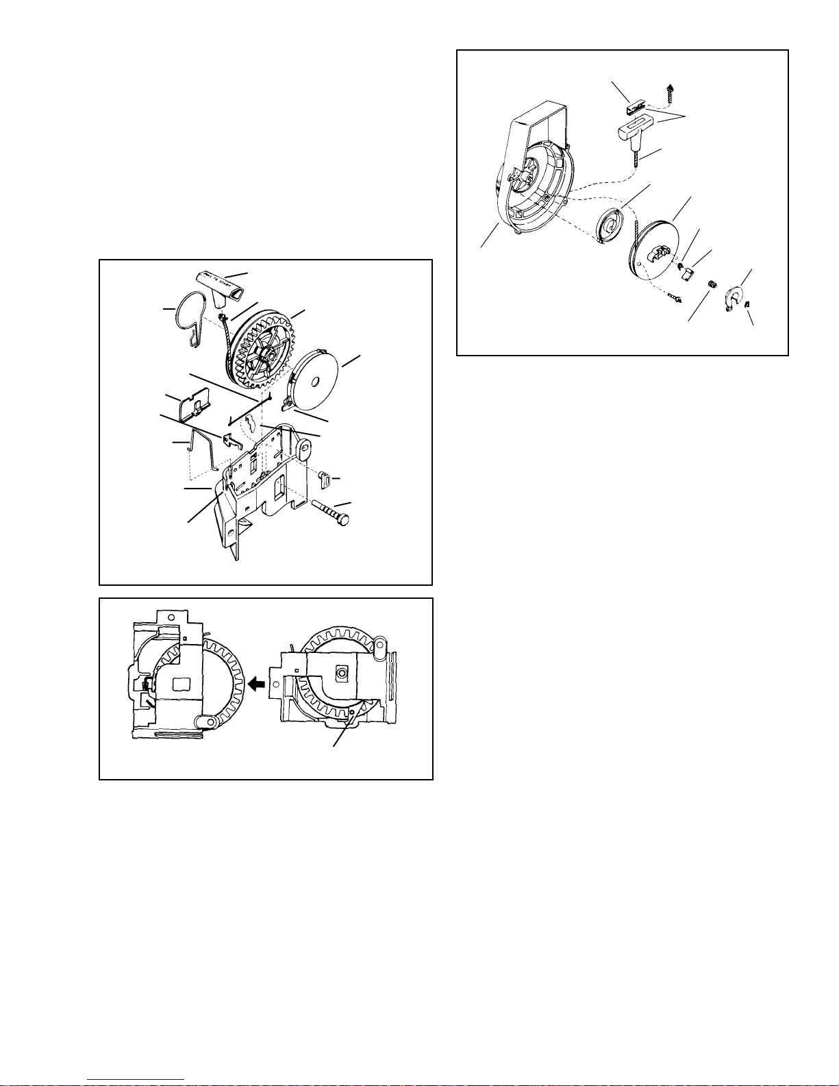
6. If the starter is equipped with a locking or delay
pawl and spring, make sure these are in place before
grasping the gear and spring capsule assembly
and sliding it into the bracket. Make sure the legs
of the brake spring are positioned in the slots of
the bracket.
7. Feed the rope end under the rope guide and hook
it into the "V" notch. Remove the pin and the strut
will rotate clockwise against the bracket.
8. Insert the new center pin by pressing or driving
the pin firmly in place. Reinstall the starter assembly
on the engine.
STARTER HANDLE
BRAKE
ROPE
PAWL SPRING *
CLIP *
KEY*
ROPE CLIP
PULLEY
SPRING
ASSY.
STRUT
PAW L
HANDLE INSERT
HANDLE
STARTER ROPE
REWIND SPRING
PULLEY
RETURN SPRING
HOUSING
ASSY.
BRAKE SPRING
STARTER DOG
BRAKE
TRUARC
"E" CLIP
ASSEMBLY PROCEDURE.
1. Hook loop of spring into housing and wind in housing
in a counterclockwise direction. The spring should
have a light coating of grease on it.
2. Place pulley into housing.
BRACKET
"V"ROPE WEDGE
* USED ON SOME MODELS
GUIDE BRAKE ENDS
THROUGH SLOT
WHEN PIN IS REMOVED STRUT
WILL ROTATE 45o CLOCKWISE
LOCKING PAWL*
PIN
REWIND STARTER MOUNTED IN HOUSING
DISASSEMBLY PROCEDURE.
1. Pull rope out to untie knot in rope and slowly release
spring tension.
3. Install dog spring and dog in starter pulley in the
socket closest to the rope hole in pulley.
4. Replace brake spring, brake and install E clip.
5. To put tension on spring, wind pulley
counterclockwise until tight, then allow to unwind
until the hole in the pulley lines up with the eyelet
in housing, then install rope and handle.
2. Remove E clip, brake, brake spring, starter dog
and return spring.
3. Lift out pulley; rewind spring is located in the housing.
Replace all worn or damaged parts.
25
Page 29
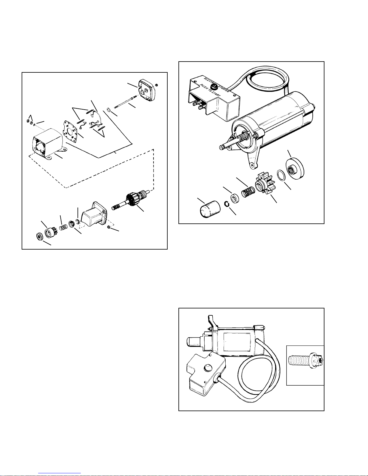
ELECTRIC STARTERS
The following electric starter illustrations will not be
identical in configuration to the starter being serviced,
but tests apply unless otherwise stated. Starters labeled
CSA cannot be serviced, except for external components.
END CAP
BRUSHES
BRUSH SPRINGS
NUTS
WASHER
SPRING
GEAR
HOUSING
RETAINER
RING
BRUSH
CARD
BRUSH
SPRINGS
BRUSH CARD ASSY.
THRUST WASHER
BOLT
ARMATURE
The following starter, number 590556, is a sealed UL
and CSA approved starter, and the only component
that can be serviced is the drive assembly.
ENGAGING NUT
ANTI DRIFT SPRING
SPRING RETAINER
DUST COVER
RETAINER RING
FRICTION
WASHER
GEAR
SPRING RETAINER
LOCKNUT
ENGAGING NUT
DRIVE ASSEMBLY SERVICE. Pinion gear parts should
be checked for damage or wear. If the gear sticks on
the shaft, it should be washed in solvent to remove
dirt and grease, then dried thoroughly. If damaged,
replace with new parts.
On units with the gear under the cap assembly, use
the following procedure for disassembly:
1. Remove retainer ring from armature shaft.
2. Remove the two nuts from the through bolts holding
on the cap assembly.
3. Slide off the cap assembly. The engaging nut,
gear, spring and spring retainer will remain in the
cap assembly.
4. Remove, inspect, and replace as necessary.
Use reverse procedure for assembly.
To disassemble the drive assembly, use the following
procedure:
1. Remove plastic dust cover.
2. Push down spring retainer and remove retainer
ring.
3. Slide off spring retainer, anti-drift spring, gear,
friction washer, and engaging nut. Inspect and
replace as necessary.
Use reverse procedure for assembly.
TORX® E8
HEAD SCREW
26
The 590556 Electric Starter uses a mounting screw
with a Torx® E-8 head. To torque this screw you must
use a 670307 Torx® E-8 socket.
Page 30
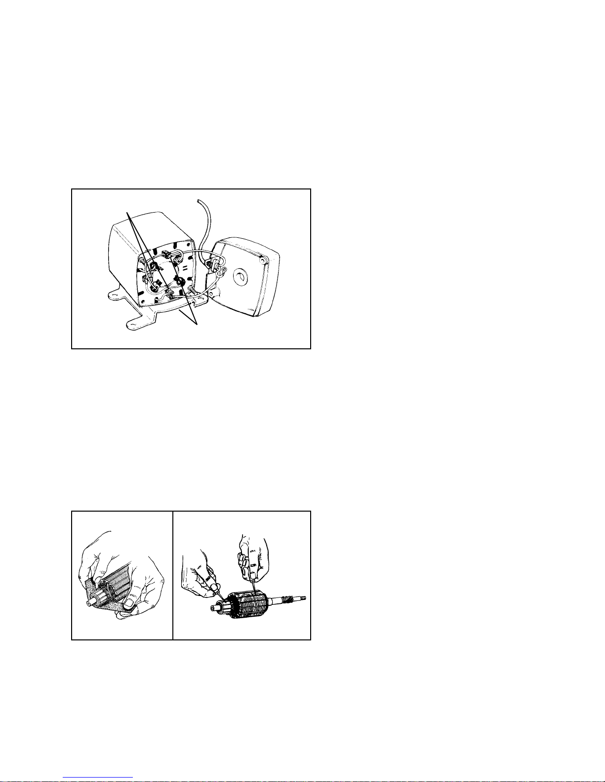
STARTER CHECKING AND SERVICE. Remove nuts
at both ends of the starter and take off rear end cap.
CHECK BRUSHES. Before removing the armature,
check brushes for wear. Make sure brushes are not
worn to the point where the brush wire bottoms out
in the slot of the brush holder. Brush springs must
have enough strength to keep tension on the brushes
and hold them against the commutator.
If brushes need replacement, remove by unhooking
the terminals or cutting the connections and then
resoldering. If the brush card is warped from overheating,
replace the card assembly.
FIELD COIL
CONNECTORS
TROUBLESHOOTING STARTERS.
STARTER DOES NOT FUNCTION. Check for:
1. No current to the starter caused by faulty connections
or blown circuit breaker.
2. Faulty safety switches, ignition, starter switch, or
solenoid.
3. Engine locked up or parasitic load on engine.
4. Shorted, open, or grounded field coil.
5. Open, shorted, or bent armature.
6. Brushes sticking or damaged.
7. Dirty or oily brushes or commutator.
STARTER CRANKS ENGINE SLOWLY. Check for:
1. Parasitic load or tight engine.
2. Worn brushes or weak brush springs.
3. Dirty, oily, or worn commutator.
4. Worn bearings in cap assemblies.
5. Defective armature.
CONNECTION POINTS
OF POWER CORD LEADS
CHECK FIELD. Using a continuity light or ohmmeter,
check the field by attaching one lead to each field coil
connection. Continuity should exist between these two
points. Check continuity between each field coil
connection and the starter housing. No continuity should
exist.
ARMATURE CHECK. If the commutator bars are glazed
or dirty they can be turned down on a lathe. While
rotating, hold a strip of 00 sandpaper lightly on the
commutator, and moving it back and forth. (Do not
use emery cloth). Recut the grooves between the
commutator bars to a depth equal to the width of the
insulators.
STARTER SPINS, ENGINE DOES NOT CRANK. Check
for:
1. Pinion gear sticking on shaft.
2. Damaged pinion or flywheel ring gear.
Use a continuity tester to make certain no continuity
exists between the commutator (copper) and the iron
core of the armature, rotate armature and check out
all commutator bars.
The armature can be thoroughly checked with a growler
if available.
27
Page 31
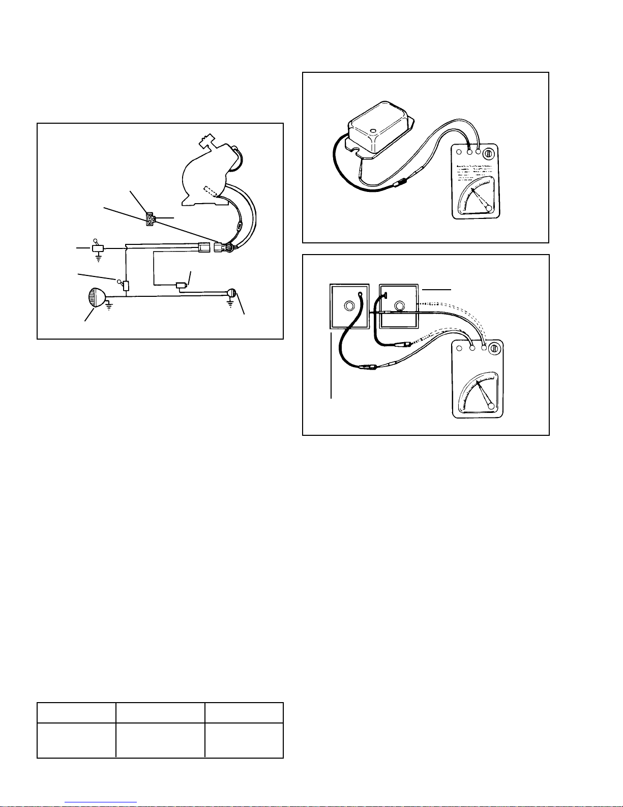
ALTERNATORS
Some engines are equipped with an alternator and regulator
to supply current to power head lights, tail lights, etc.
on recreation vehicles. Shown here is a typical wiring
diagram.
HEAD & TAIL LIGHT
STOP LIGHT
MAGNETO
GROUND
SWITCH
LIGHT
SWITCH
HEAD LIGHT
MAGNETO
GROUND
STOP LIGHT SWITCH
TAIL STOP LIGHT
CHECKING THE SYSTEM. At an idle speed (2600
R.P.M.) a slight dimming of the lights will be noticed,
This is normal and should not be considered faulty.
(MOUNTED ON BLOWER HOUSING OR COVER PLATE)
TYPE A
RED
LEAD
OHM METER
(MOUNTED ON BLOWER HOUSING)
VIEW FROM BOTTOM
TYPE
TYPE C
B
RED LEAD
Before going into extensive checks, be sure to examine
the more basic causes first, such as:
1. Make sure bulbs are good and the right ones are
being used. Number 1157 for tail & stop light; 4416
or 4420 for head lights.
2. Corroded terminals.
3. Cracked wire insulation.
4. Broken wires.
5. Broken wires covered by insulation.
6. A wire grounding out the system.
7. Loose connections.
8. Make sure regulator has good ground.
9. Faulty Switch.
Check the regulator for resistance. If regulator checks
out and all bulbs and wiring are ok, replace alternator
coils.
Three types of regulators have been utilized. Use the
ohm readings in the chart below for the type that you
are servicing. Readings should be as follows:
VIEW FROM BOTTOM
OHM METER
Type A Type B Type C
100 to 200 Over 50,000 100 to 200
Ohms Ohms Ohms
28
Page 32

FLYWHEEL (INSIDE-EDGE) BRAKE SYSTEM
Tecumsehs brake systems provide two methods of
meeting compliance standards which has become a
Federal law as of June 30, 1982. There are two additional
methods used by equipment manufacturers that also
meet compliance standards, they are:
1. Use of the blade brake clutch in conjunction with
either a top or side mounted recoil starter. The blade
stops within three seconds after the operator lets
go of the blade control bail at the operator position
and the engine continues to run. Starter rope handle
is on the engine.
2. Use of a recoil starter (top or side mounted) with
the rope handle on the engine as opposed to within
24 inches from the operator position. This method
is acceptable if the mower deck passes the 360
degree foot probe test. A specified foot probe must
not contact the blade when applied completely around
the entire blade housing. This alternative can be
used with engine mounted brake systems and typical
bail controls. The blade stops within three seconds
after the operator lets go of the blade control bail
at the operator position and the engine is stopped.
Tecumsehs Flywheel (Inside-Edge) Brake System
provides consumer safety by shutting down the engine
and lawnmower blade within seconds after the operator
releases the Engine/Blade control at the handle of the
lawnmower.
INSIDE EDGE SYSTEM
In the stop position the brake pad is applied to the
inside edge of the flywheel, at the same time the ignition
system is grounded.
In order to restart the engine, the brake control must
be applied. This action pulls the brake pad away from
the inside edge of the flywheel and opens the ignition
kill switch. On electric start systems the starter is
energized by an ignition switch or a two motion control.
On non-electric start systems, the recoil starter rope
must be pulled to start engine.
COMPONENTS
The Inside Edge system uses the following components:
The brake lever and pad assembly consists of a steel
lever with a brake pad bonded to the lever.
The ignition kill switch is a plastic block with a wire
extending out of it. The wire is attached to a terminal
which is connected to the ignition kill wire. The brake
lever contacts and grounds the wire of the switch when
the engine / blade control is released, and the ignition
module is grounded. This in turn kills the ignition.
The interlock switch is a push button switch that is
activated by the brake lever when the engine / blade
control is actuated. If there is a starter switch used
to start the engine, the interlock switch acts as a safety
switch and will not allow the starter to crank unless
the engine / blade control is depressed.
Where a two motion control is used the interlock switch
is utilized as the starter switch.
The Torsion Spring supplies the pressure to the brake
lever and brake pad to stop the flywheel.
The Control Cable transfers the motion of the
engine / blade control to the brake system.
SERVICE
If the brake system fails to kill the ignition and stop
the blade within 3 seconds the following service procedures
should be followed.
Remove the flywheel as outlined in "IGNITION" section.
NOTE: BEFORE THE FLYWHEEL IS REMOVED OR
REPLACED, THE BRAKE PRESSURE ON THE
FLYWHEEL MUST BE RE-LEVELED AS OUTLINED.
IGNITION SHORTED
IGNITION OPEN
BRAKE APPLIED
BRAKE RELEASED
29
Page 33
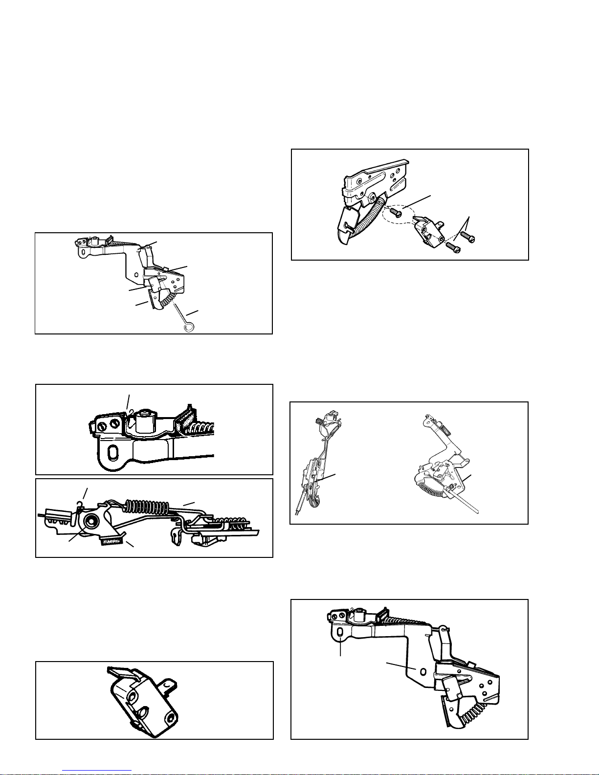
INSIDE EDGE
To relieve the brake pressure on the flywheel, compress
the spring by moving the lever toward the spark plug,
when the hole in the lever aligns with the hole in the
bracket, secure the lever with alignment tool 670298
then remove the flywheel (diag. 7). Remove the alignment
tool. Release the spring tension by unhooking the short
end of the spring from bracket with a pliers. Remove
the E clip from the brake pad shaft. Slide the pad
lever from the shaft and unhook the link. Inspect the
brake pad for dirt, oil or grease contamination. If the
pad is contaminated, or if there is less than .060" (1.524
mm) of brake pad material at the pad's thinnest point,
replacement is necessary. The brake pad is bonded
to the brake lever and must be replaced as an assembly.
Rehook the link, install the brake lever and pad assembly,
install the "E" clip, rehook the short end of the spring
and continue to reassemble the brake system in the
reverse order of disassembly.
SHORT END OF SPRING
ALIGN HOLES
SWITCH
LEVER
670298
IGNITION GROUND OUT TERMINAL
Inspect the ignition kill switch grounding clip for proper
alignment and contact with the brake arm. Insure that
all electrical connections are clean and secure.
GROUNDING CLIP
To replace the interlock switch, carefully grind the
heads off of the rivets that fasten the interlock switch
to the brake bracket. Remove the rivets from the back
side of brake bracket. Use the self-tapping screw
supplied with the new switch to make threads in the
bracket. Install the interlock switch onto the brake
bracket in the proper position and secure the switch
to the brake bracket with the machine screws supplied.
Be careful not to overtighten the screws as switch
breakage can occur.
SELF TAPPING
SCREW
MACHINE
SCREWS
CONTROL CABLE
INSIDE EDGE
If replacing the cable conduit screw with a screw other
than a service part replacement, be certain that the
screw length is not too long as to prevent free travel
of the lever. Make sure the button on the starter interlock
switch is completely depressed when the control is
fully applied. The cable must provide enough travel
so the brake will contact the flywheel. Some slack
should exist in the cable adjustment to compensate
for brake pad wear.
GROUNDING CLIP POSITION
LINKAGE
"E" CLIP
BRAKE PAD
STARTER INTERLOCK SWITCH
The engine / blade control must close the interlock
switch before the starter can be engaged. To check
the interlock switch, use an ohmmeter or continuity
light to perform a continuity check. Continuity should
exist between the two terminals when the interlock
switch button is completely depressed. No continuity
should exist when the button is released. If the switch
fails replace the switch.
SCREW END MUST
NOT BLOCK LEVER
ACTION
CABLE CLAMP
SCREW
When installing a inside edge brake bracket assembly,
be sure the slotted holes in the brake bracket are all
the way down on the fasteners. This will properly align
the brake bracket to the flywheel brake surface.
MOUNTING HOLES
Ô
Ô
MECHANISM FULL DOWN
BEFORE SCREWS TORQUED
30
Page 34
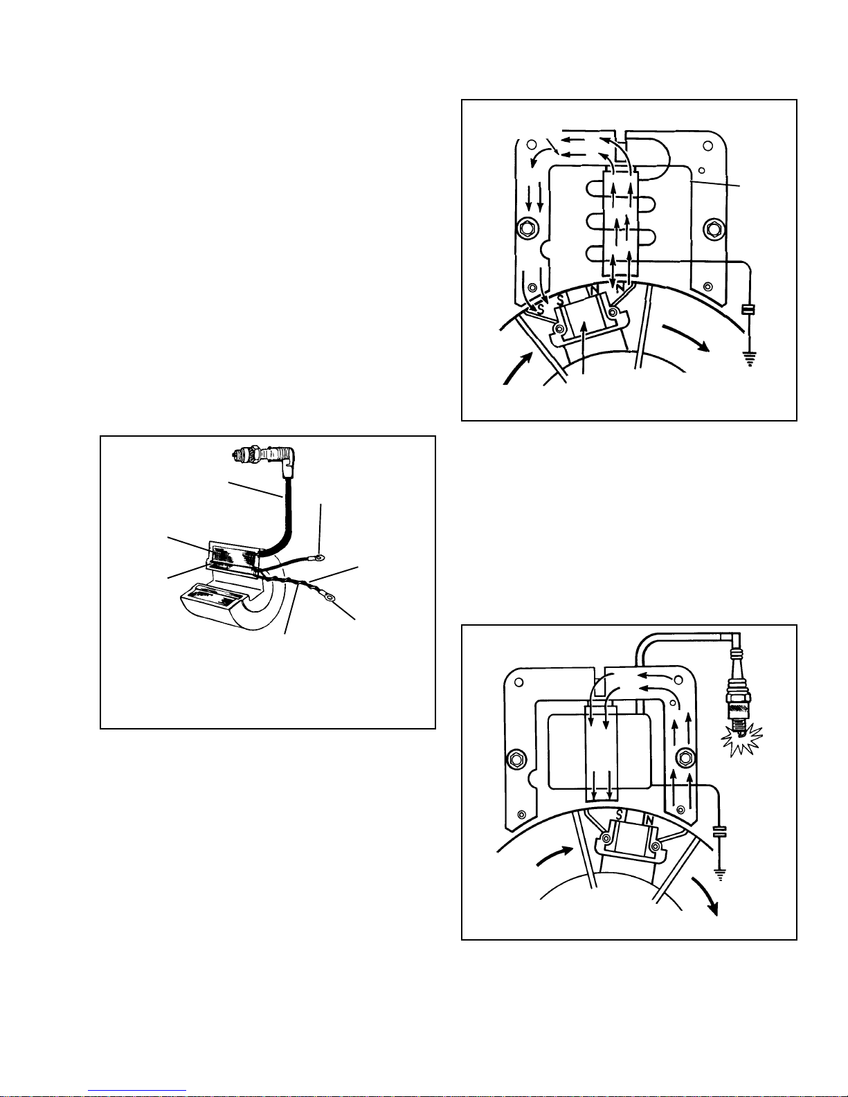
IGNITION
IGNITION OPERATION
(PRE-1985 Production)
MAGNETO IGNITION. Tecumsehs magneto ignition
consists of a stator assembly made up of a coil,
laminations, contact points, condenser, and a permanent
magnet mounted in the flywheel of the engine.
COIL: The coil consists of a primary and a secondary
winding of wire. The primary is the low voltage (200300 volts) primary winding consists of about 150 turns
of heavy gage wire next to the core. One end of the
primary is connected to the insulated contact point
and the other end is grounded to the stator body.
The secondary winding consists of extremely fine wire
with many turns (about 10,000) wrapped over the primary
windings. One end connects to the spark plug and
the other end is grounded to the stator body.
The coil is used as a transformer to increase the primary
voltage to a high voltage (10,000 - 20,000 volts) which
jumps across the spark plug gap.
SECONDARY
LEAD
SECONDARY
WINDING
PRIMARY
WINDING
SECONDARY
GROUND LEAD
PRIMARY LEAD
PRIMARY
GROUND
LEAD
GROUND LEAD
TERMINAL
FOR PRIMARY
AND SECONDARY
PATH OF MAGNET
LINES OF FORCE
PRIMARY
WINDING
FLYWHEEL
MAGNET
ROTATION
POINTS
CLOSED
As the flywheel continues to rotate, the North Pole
approaches the last leg of the lamination stack. The
magnetic field through the center leg reverses, producing
a large change in the magnetic field and a high current
in the primary windings of the coil.
At this time, the contacts open and the primary current
stops flowing. This change in current causes a voltage
in the primary windings, which induces the high voltage
in the secondary winding of the coil. The voltage is
routed through the spark plug wire, to the spark plug,
and then jumps the gap of the plug to ignite the fuel
air mixture.
*The actual connection of the primary and secondary ground is
normally made inside of *the coil, but it is shown above to illustrate
the individual wires.
CONTACT POINTS. The contact points consist of an
insulated movable point that connects to the coil primary
lead and a stationary point that is grounded to the
stator body which provides the return path for the
primary circuit.
CONDENSER. The condenser acts as an electrical
shock absorber to prevent arcing between the contact
points as they open. Arcing lowers the voltage at the
spark plug, as well as burn and pit the contact points,
thus shortening point life.
OPERATION OF THE TECUMSEH MAGNETO
IGNITION. As the flywheel turns, the magnets (mounted
in the wheel) pass the coil mounted on the stator. As
the magnets North Pole enters the area of the center
leg of the stator, a magnetic field is concentrated through
the laminations to the magnets South Pole. This causes
a generation of current flow in the coils primary winding.
The ignition points are closed.
POINTS OPEN
31
Page 35
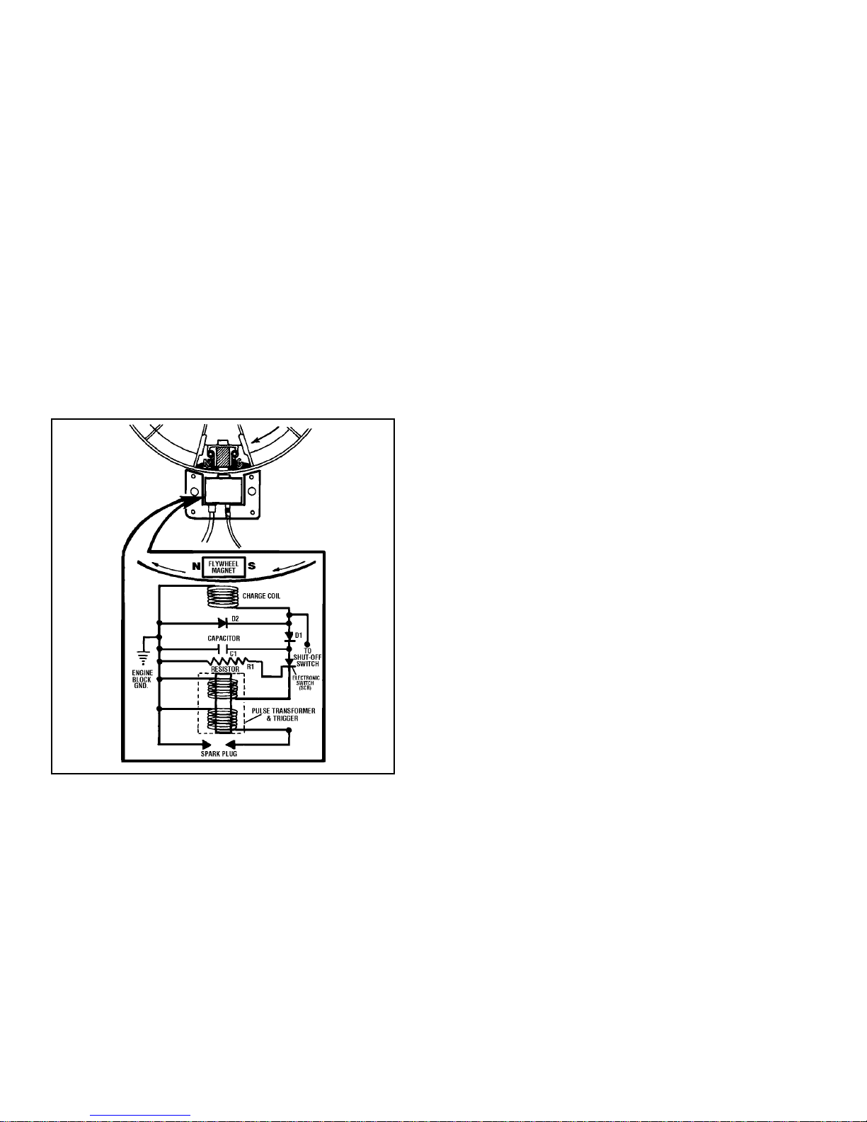
1985 to Present
SOLID STATE IGNITION. Tecumsehs solid state
capacitor discharge ignition (CDI) is an all electronic
ignition system and is encapsulated in epoxy for
protection against dirt and moisture.
SOLID STATE IGNITION OPERATION. As the magnets
in the flywheel rotate past the charge coil, electrical
energy is produced in the module. This energy is
transferred to a capacitor where it is stored until it is
needed to fire the spark plug.
The magnet continues rotating past a trigger coil where
a low voltage signal is produced and closes an electronic
switch (SCR).
The energy which was stored in the capacitor is now
transferred through the switch (SCR) to a transformer
where the voltage is increased from 200 volts to 25,000
volts. This voltage is transferred by means of the high
tension lead to the spark plug, where it arcs across
the electrode of the spark plug and ignites the fuelair mixture.
32
Page 36
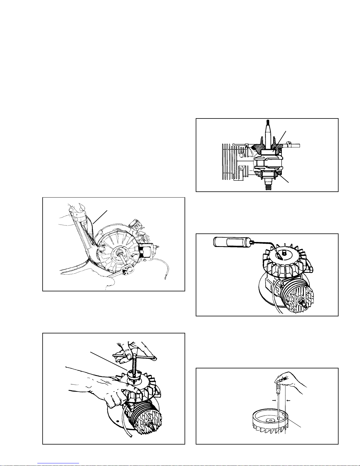
IGNITION SERVICE
SPARK PLUG SERVICE. Spark plugs should be cleaned
and adjusted periodically. Check point gap with wire
feeler gauge (.030" - .762 mm) and adjust gap. Replace
if points are pitted and burned or the porcelain is cracked.
Refer to Master Parts Manual or Micro-Fiche for correct
replacement number.
If spark plug fouls frequently, check for the following
conditions:
1. Carburetor set too rich.
2. Choke not opening fully.
3. Poor grade gasoline.
4. Clogged exhaust system.
5. Incorrect spark plug.
6. Improper oil fuel ratio.
7. Inconsistent spark.
NOTE: Ensure cleaned spark plugs are free of
all foreign material before installation.
FLYWHEEL REMOVAL AND SERVICE. To remove
flywheel, use a strap wrench Part No. 670305 to hold
the flywheel and remove the nut by turning it in the
direction opposite of crankshaft rotation.
STRAP WRENCH
670305
NOTE: A KNOCK-OFF TOOL IS NOT RECOMMENDED
FOR ENGINES WITH A BALL BEARING ON THE
MAGNETO END OF THE CRANKSHAFT.
NOTE: If a knock-off tool is used, the pounding may
cause the ball bearing to dislodge from the shroud
base and force the lower thrust face of the crankshaft
against the cylinder thrust face. TO CORRECT THIS
CONDITION RAP SHARPLY WITH RAWHIDE MALLET
ON THE P.T.O. END TO PROVIDE CLEARANCE
BETWEEN CRANKSHAFT AND CYLINDER THRUST
FACE.
BALL BEARING
MUST HAVE
CLEARANCE
If the flywheel is difficult to remove from the crankshaft
because of rust, etc., the use of a propane torch can
be helpful. Heat the area immediately outside of the
crankshaft. The aluminum alloy in the flywheel should
expand enough to break the seal away from the steel
crankshaft.
NOTE: Do not attempt to remove flywheel using a
jaw type pullers on the outer diameter of the flywheel
or flywheel breakage will occur.
On engines with cored holes (not tapped) use flywheel
puller part No. 670306.
FLYWHEEL PULLER
670306
FLYWHEEL MAGNETS. The magnets in the flywheel
rarely lose their magnetic strength. If magnets are
suspected to be faulty, place the flywheel upside down
on a wooden surface. Hold a screwdriver by the extreme
end of handle with the point down. Move the blade to
within 3/4 inch of magnets. The magnets should attract
the screwdriver blade against the magnet.
SCREWDRIVER LENGTH
APPROXIMATELY
6" (15.24 cm)
3/4" (19 mm)
MAGNETS
33
Page 37
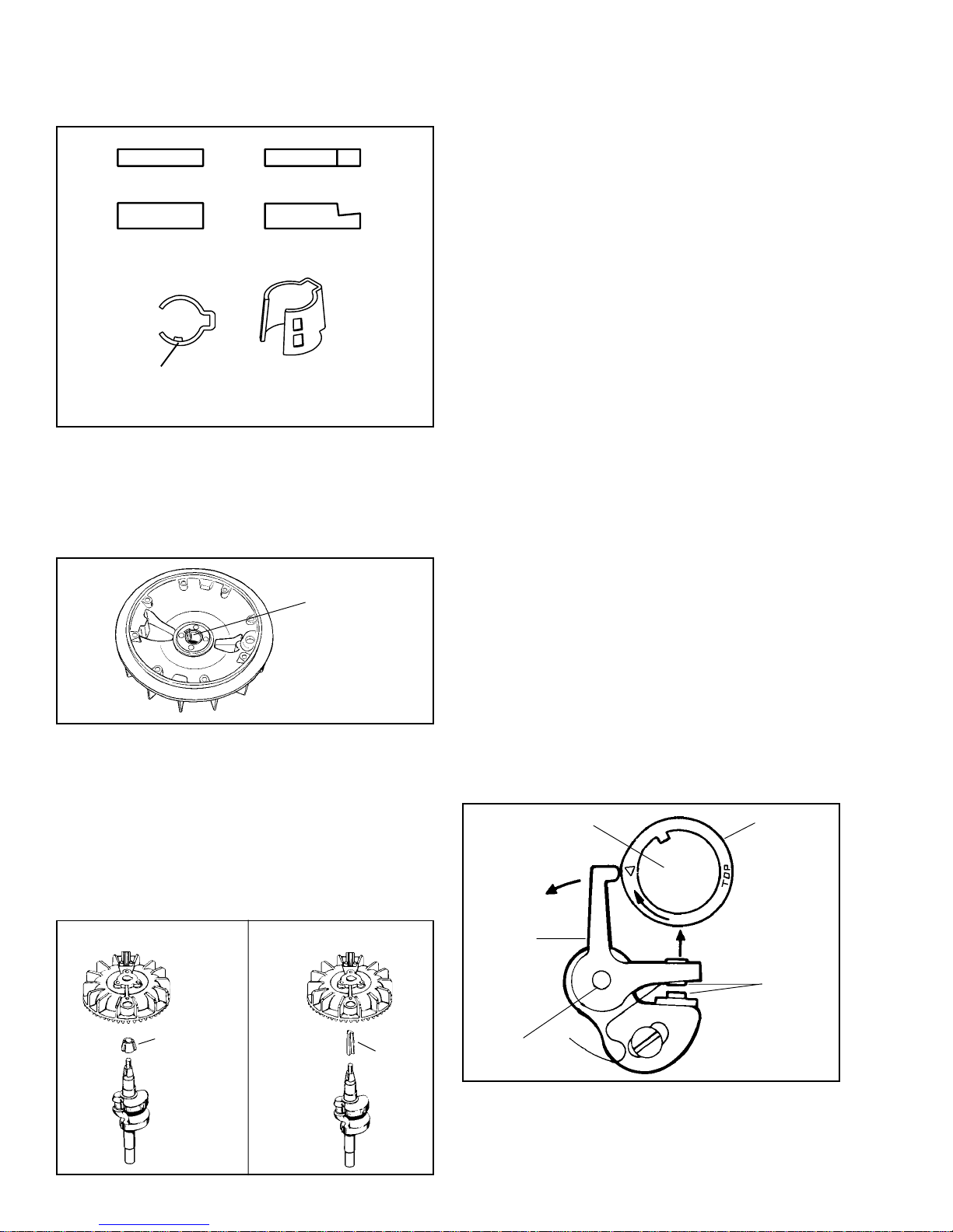
FLYWHEEL KEYS. The flywheel key locates the flywheel
to the crankshaft in the proper position. If a flywheel
key is sheared, or partially sheared, the engine will
not start or may be difficult to start.
FLYWHEEL TORQUE. Torque flywheel to the proper
specification. See the tables in specification section
for the proper torque setting.
Loose lawn mower blades and adapters can contribute
to sheared keys.
REPLACING MAGNETO BREAKER POINTS. Remove
the nut holding the electrical leads to the screw on
the movable portion of the breaker points.
STEEL
CRANKSHAFT
TIMING
TABS
ALUMINUM
ALLOY
GOLD
SOLID STATE
IGNITION
NOTE: Use the Tecumseh Master Parts Manual to
determine correct key for the application.
ADAPTER KEY TO FLYWHEEL ASSEMBLY. When
an adapter is used, place the adapter with its raised
key area in the flywheel keyway before putting the
flywheel on the engine.
SLEEVE TO BE
PRESSED IN
FLUSH
WITH HUB
Remove the screw from the stationary breaker point
and remove point set. Reinstall the new breaker point
set into position and adjust the point gap according
to the specifications. Points must be adjusted, when
the rubbing block of the points is on the highest spot
on the breaker cam.
Clean points by putting lint-free paper between them
and sliding it back and forth. Then open points and
remove paper and any paper fiber remaining between
the point set. Any oil, fingerprints or contamination
will cause the points to burn prematurely.
CONDENSER CHECK. Check condenser on a good
quality tester, following the test equipment
manufacturers instructions to check capacity and
resistance. Replace condenser if condition is
questionable.
IGNITION COIL. Inspect the coil for cracks in insulation
or other damage. Make sure electrical leads are intact,
especially where they enter the coil.
Check operation of the coil using an approved tester
following the instructions furnished with the test unit.
If laminations are distorted or damaged, replace. Some
coils are permanently attached to the laminations and
must be serviced as an assembly.
FLYWHEEL SLEEVE. Some engines utilize a sleeve
between the crankshaft and flywheel which acts as a
flywheel key. If this sleeve becomes sheared or
damaged, replace. The flywheel sleeve is pressed
into the crankshaft opening in the flywheel, and should
be flush or slightly below flush from the inside surface
of flywheel before in stalling on crankshaft.
For engines equipped with brake system, a new key
and flywheel are shown. Torque procedures are the
same.
NON-COMPLIANCE ENGINE COMPLIANCE ENGINE
FLYWHEEL
SLEEVE
KEY
IGNITION TIMING. Begin procedure by setting the
point gap. This is done by rotating the crankshaft until
the point arm is resting on the high side of the ignition
cam. Set the point gap by loosening the screw on
the movable point, and insert a feeler gauge per
specification. Tighten the screw then recheck the gap.
CRANKSHAFT
ARM
PIVOT
CAM
POINTS
34
Page 38
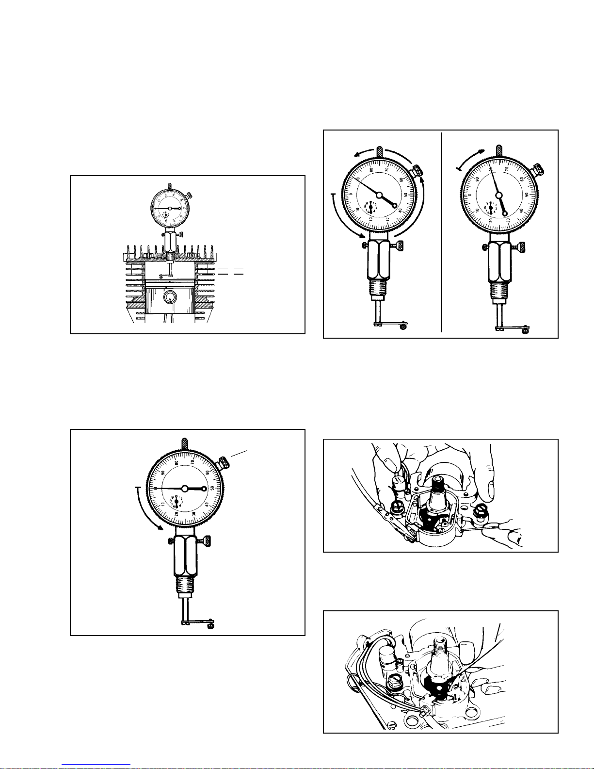
Install dial indicator (Part No. 670241) equipped with
the correct tip on the extender leg. Use the small tip
for engines with timing dimensions of between Top
Dead Center and .050 (1.27 mm) BTDC . Use the
large tip for engines with timing dimensions of between
.051" (1.29 mm) BTDC to .150 (3.81 mm) BTDC.
Loosen the screw on the side of the adaptor sleeve
to allow the sleeve to be turned into the threads of
the spark plug hole, not the entire dial indicator. This
will ensure the proper location of the tip. Once the
adapter sleeve is secured in the hole, tighten screw
on sleeve adaptor to prevent the dial from moving
up or down, which would give a false reading.
T.D.C.
B.T.D.C.
While watching the needle on the dial indicator, rotate
the crankshaft counterclockwise (when looking at the
magneto end of the crank) past the specified Before
Top Dead Center (BTDC) dimension. Then rotate
the crankshaft back clockwise to the proper dimension,
this will take out any slack between the connecting
rod and crankshaft assembly.
(Using .080 (2.0 mm) BTDC dimension as an example.)
DIAL AT .090” (2.29 mm) DIAL AT .080” (2.0 mm)
Find top dead center (TDC) by rotating the crankshaft
clockwise (when looking at the magneto end of the
crank) until the needle on the dial stops and reverses
direction. Where the needle stops is TDC. Loosen
the screw on the dial, and rotate the dial so that zero
is lined-up with the needle at TDC. Tighten the screw
on the dial to secure it in place.
DIAL AT 0
DIAL SCREW
Next, disconnect the leads from the point terminal,
and be sure to reinstall the securing nut & tighten it
up. Connect one lead of a continuity light, or Ohmmeter
to the point terminal and the other lead to a good
ground. Loosen the two bolts holding down the stator
and rotate the stator until the continuity light or Ohmmeter
indicates a break in the circuit. At this point torque
down the stator bolts and the timing procedure is
completed.
Before putting the dust cover back on the points box,
clean the points by sliding lint free paper back and
forth between the contacts. Manually, open the points
when removing the paper to eliminate paper fibers
from remaining between the contact points.
LINT FREE P APER
35
Page 39
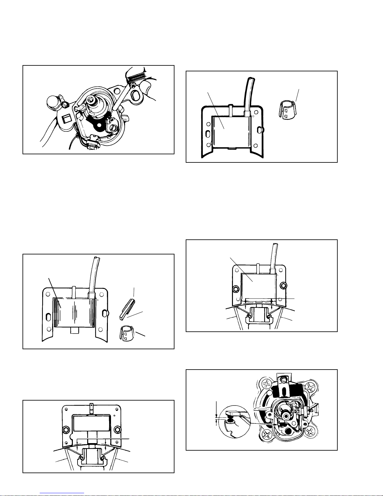
FIXED TIME SYSTEM (External Coil). This system
has the contact points and condenser mounted under
the flywheel with the laminations and coil mounted
outside the flywheel. This system is identified by the
square hole in the stator, the round configuration of
the coil, and a stepped flywheel key.
SOLID STATE (CDI). This is an all electronic ignition
system with the components sealed in a module and
located outside the flywheel.
A Solid State module can be identified by its square
configuration, which will identify the need for the proper
flywheel key or sleeve.
Begin the timing procedure, torque down the stator
bolts to secure the stator in place. Next rotate the
crankshaft until the point arm is resting on the high
side of the ignition cam. Set the point gap at to the
proper specification by loosening the screw on the
movable point, and inserting a feeler gauge between
the contact points. Tighten the screw on the movable
point and then recheck the point gap. Be sure to clean
the contact points with lint free paper.
Reinstall the proper flywheel key, flywheel, washer,
and torque down the flywheel nut to specification.
Reinstall the external coil, but do not tighten down
the mounting screws.
SQUARE MODULE
FLYWHEEL SLEEVE
The proper air gap setting between the flywheel magnets
and the laminations on both the fixed time and CDI
systems is .0125'. Place .0125' gauge, part No. 670297
between the magnets and laminations and torque down
mounting screws to specification. Recheck gap setting
to make certain there is proper clearance between
the magnets and laminations. NOTE: Due to variations
between pole shoes, air gap may vary from .005/.020'
when flywheel is rotated. There is no further timing
adjustment on external lamination systems.
SQUARE MODULE
ROUND COIL
STEPPED KEY
STEPPED
END
TOWARD
ENGINE
FLYWHEEL
SLEEVE
Timing this system consists of having the proper .0125"
(.317 mm) air gap gauge, (Part No. 670297) between
the magnets and laminations and torque down the
mounting screws to specification. Remove air gap
gauge and rotate flywheel to check for any possible
striking points. If none are found, the air gap is set
correctly and the timing procedure is completed.
.0125”
(.317 mm)
.0125"
OTHER IGNITION SYSTEMS. Ignition systems on
engines with a non-adjustable stator, set the points
per specification. If the coil is located under the flywheel,
no other timing is required.
SET GAP
PER SPECIFICATION
36
Page 40
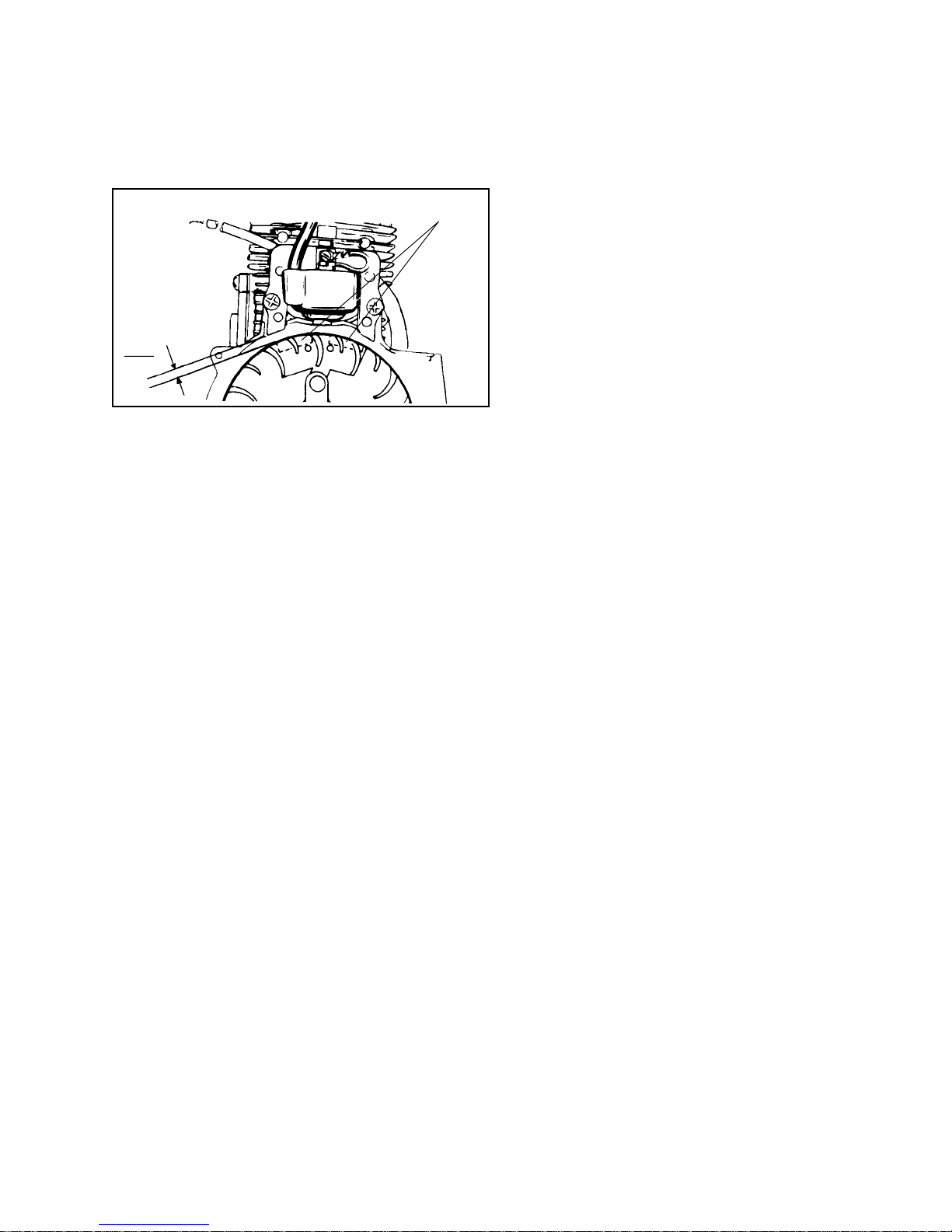
If engine has the coil and lamination outside of flywheel,
set points per specification and set air gap between
flywheel magnets and laminations to .005' to .008'.
Air gap gauge, part number 670216 which measures
.0075' may be used. Use Loctite "242 Blue" on screws
and torque down mounting screws to specification.
Remove air gap gauge.
MAGNETS
AIR GAP
DIMENSION
.005
.008
37
Page 41
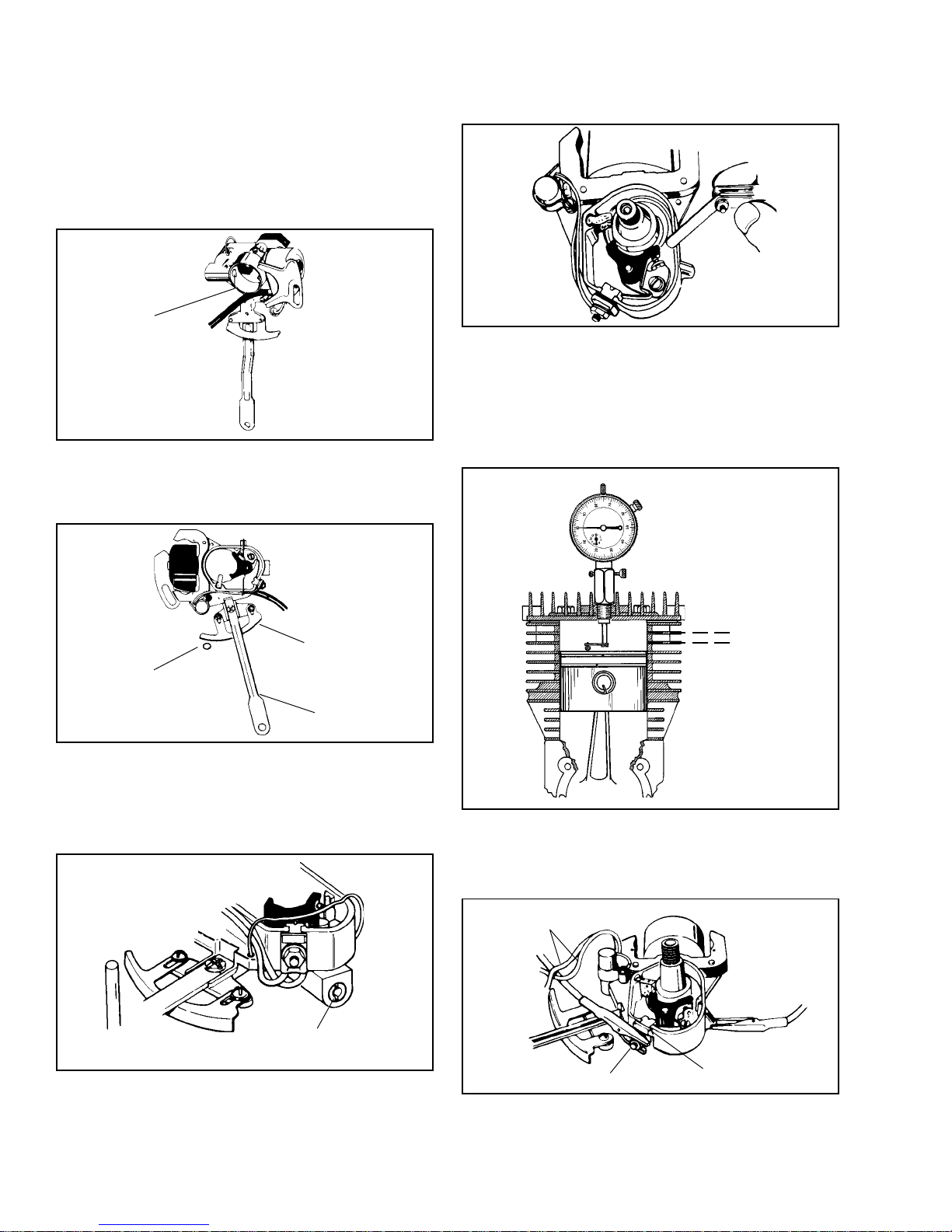
OUTBOARD TIMING
OUTBOARD TIMING. (STANDARD IGNITION). Follow
the step-by-step procedure outlined for timing outboard
engines with Standard ignition magnetos (non-solid
state).
Apply a small amount of E.P. Lithium grease to the
contact area of the friction screw. Do not turn the
screw into the radius of the stator collar.
CONTACT
AREA OF
FRICTION
SCREW
Install the stator with operating handle pointed in the
direction of the carburetor. Be sure the throttle post
is NOT INSIDE the arc of the throttle actuating cam.
Hold the throttle open when installing the stator.
Adjust ignition points to proper specification.
Clean points by sliding lint free paper back and forth
between the contacts. Manually open points when
removing paper to eliminate paper fiber from remaining
between contacts.
Using a dial indicator, set the piston to the proper
Before-Top-Dead-Center (BTDC) to the specified
dimension.
THROTTLE
ACTUATING
CAM
THROTTLE
POST
CONTROL
LEVER
Move the control lever to full retard, then move toward
full advance while tightening the friction screw until
the lever will not vibrate out of position when the engine
is running and yet can be easily rotated when speed
is adjusted.
FRICTION
SCREW
T.D.C.
B.T.D.C.
Remove leads from point terminal, then reinstall and
tighten the nut and washer. Attach a continuity device
to the point terminal post and to a good ground on
the engine as shown.
LEADS
REMOVED
POINT
NUT AND WASHER
TERMINAL POST
38
Page 42
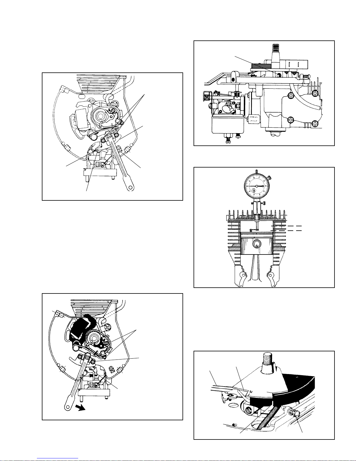
Move the stator counterclockwise, advancing the timing
until the continuity reading breaks and reads zero.
Tighten the stop bracket to secure the stator.
OUTBOARD TIMING. (SOLID STATE). Follow these
step-by-step procedures outlined for timing outboard
engines with solid state magnetos.
Loosen the actuating cam locking screws just enough
to allow adjustment of the cam. Move the actuating
cam to open the throttle completely WITHOUT causing
any binding with the throttle post.
LOCKING
SCREWS
GREASE CAM
SURFACE
THROTTLE
ACTUATING
CAM
THROTTLE POST
STOP
BRACKET
To coordinate the carburetor idle with ignition timing,
rotate the crankshaft clockwise, to .003' After-TopDead-Center (ATDC).
Rotate the control lever toward the idle position until
continuity is obtained.
FRICTION
SCREW
Using a dial indicator, set the piston to the specified
Before-Top-Dead-Center (BTDC) dimension.
T.D.C.
B.T.D.C.
Move the throttle actuating cam until it just touches
the throttle post, without moving it.
Tighten the screw slightly, then check the run position
and idle position alternately to make sure the actuating
cam is adjusted for both positions. Now tighten the
screws.
KEEP
CONTINUITY
LEADS ON
TERMINAL POST
AND GROUND
THROTTLE
ACTUATING
CAM
SET CAM SO THAT IT
JUST TOUCHES THE
THROTTLE LEVER POST
MOVE CONTROL LEVER
UNTIL POINTS OPEN
Install timing tool 670238A on the crankshaft, be careful
not to distort the keyway area.
Without disturbing the BTDC piston position, move
the control lever counterclockwise until the run trigger
aligns with the timing tool (670238A) notch marked
#1. Hold this position.
NOTE: Some models do not have the start trigger.
CONTROL
LEVER
POS. -2
TOOL 670238A
THIS SIDE UP
POS. -1
"RUN" TRIGGER
GROUND SCREW
39
Page 43
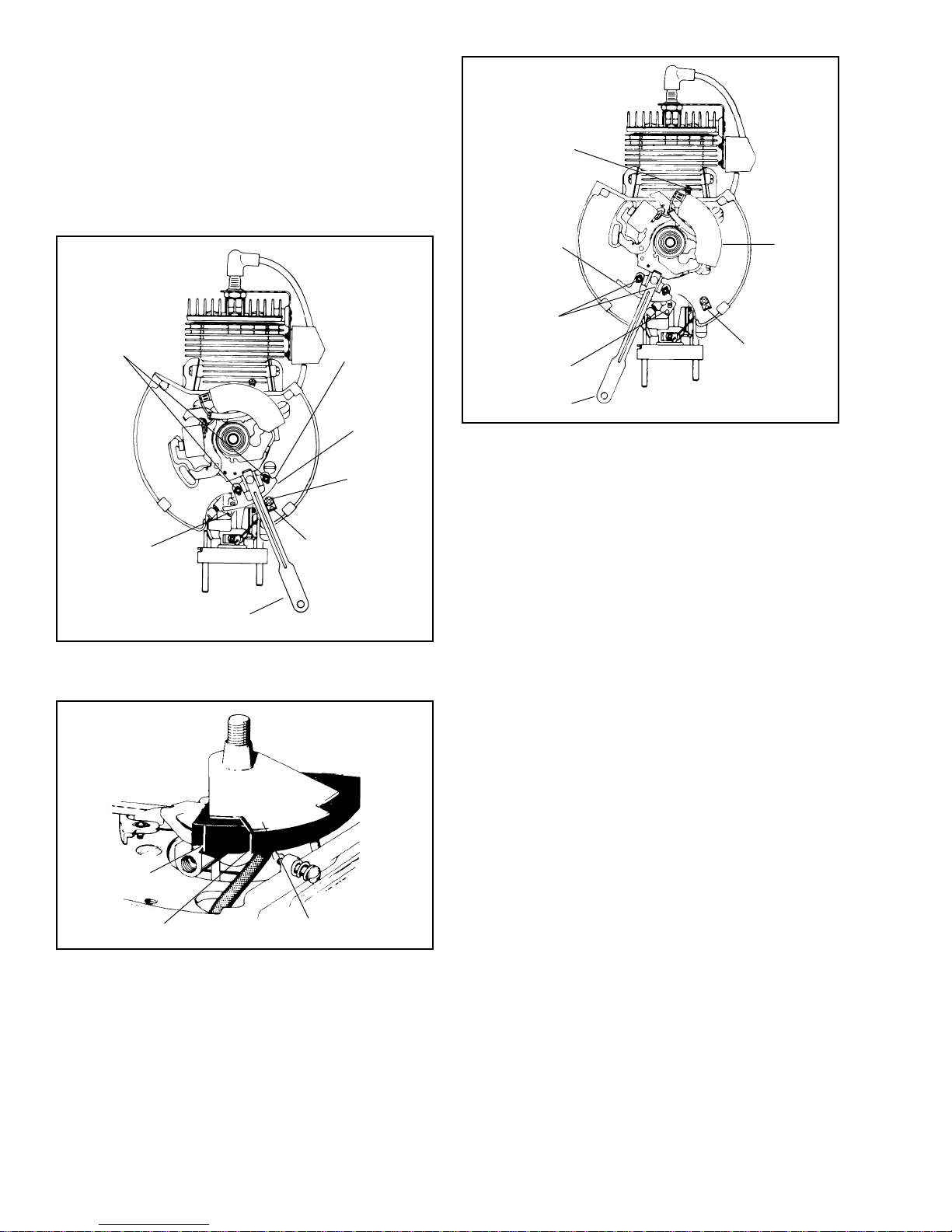
Adjust the stop bracket to prevent the control lever
from moving any further counterclockwise. Then tighten
the stop bracket screw.
Loosen the actuating cam lock screw enough to allow
adjustment of the cam. Position the cam so that it
opens the throttle completely, making sure that the
cam doesnt cause binding on the post.
When the correct position is attained, tighten the lock
screw on the high end to hold the cam in place.
LOCK SCREWS
THROTTLE
ACTUATING
CAM
GROUND SCREW
THROTTLE
ACTUATING
CAM
LOCKING
SCREWS
THROTTLE POST
"RUN"
STOP
BRACKET
GREASE CAM
SURFACE
SCREW
THROTTLE POST
CONTROL LEVER
STOP BRACKET
Move the control lever to align the RUN trigger of
the ignition unit with the number 2 position of the timing
tool. Hold this position.
TOOL 670238A
THIS SIDE UP
2
CONTROL LEVER
Recheck to insure that the high speed point hasnt
changed or that binding will not occur. Readjust from
the high speed point to the pickup point as necessary.
When assured that the cam position is correct at the
FULL RUN and IDLE positions, torque the lock screw
to 10-15 in. lbs.
"START"
TRIGGER
"RUN" TRIGGER
POS. -2
Adjust the actuating cam to touch the post without
moving it. Tighten the lock screw to hold the cam in
place.
40
Page 44
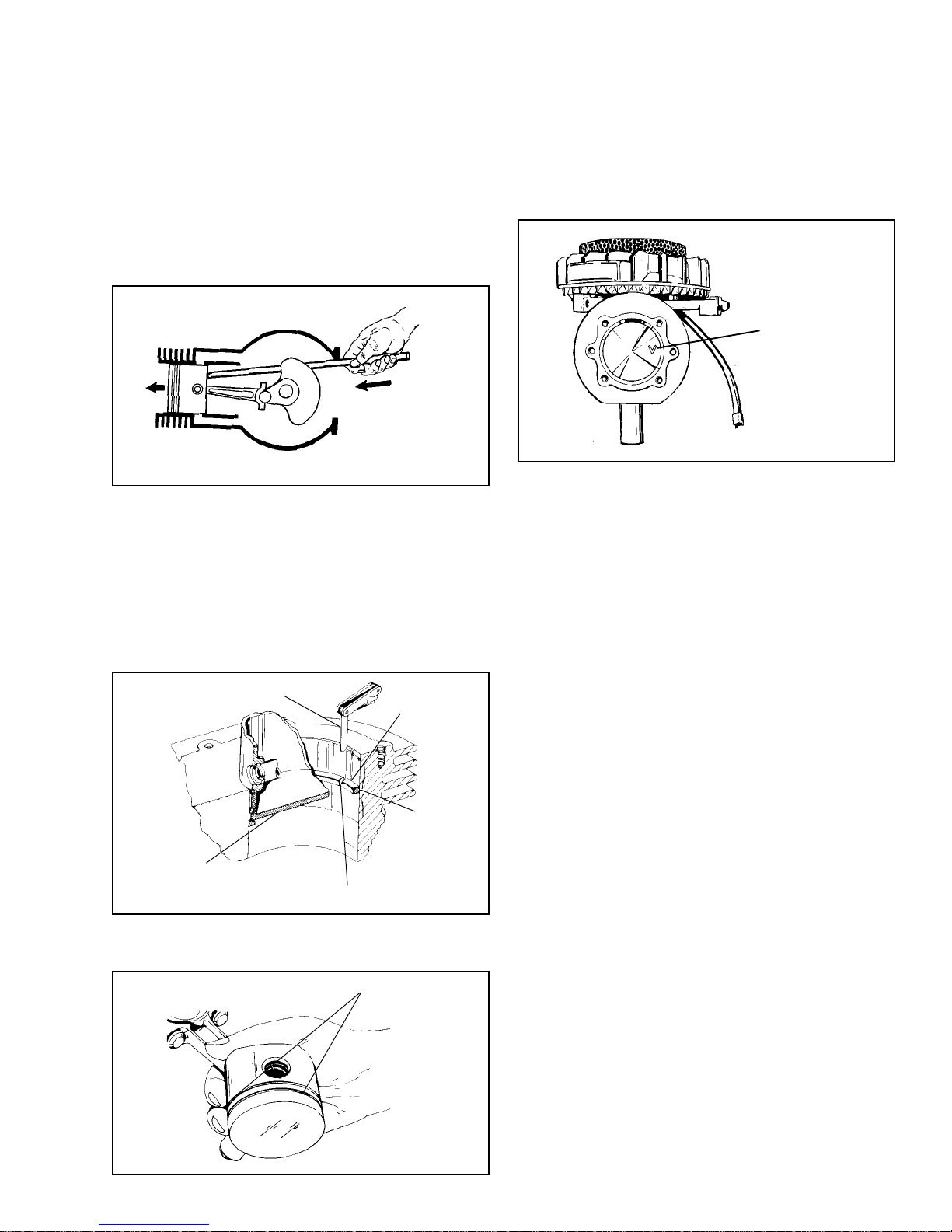
CYLINDERS & INTERNAL COMPONENTS
PISTON & RING SERVICE
Before removing the piston, clean all carbon from the
cylinder, making certain that the carbon ridge is removed
from the top of the cylinder. This will prevent ring damage
when removing the piston.
Push the piston through the top of the cylinder using
a wooden dowel on the inside of the piston so that
the connecting rod and other parts will not be damaged.
Check the piston and cylinder for scoring or other
damage.
Check the piston rings for wear by inserting them into
the cylinder to about 1/2 inch from the top of the cylinder.
Check at various places to make sure that the gap
between the ends of the ring do not exceed the
dimensions indicated in the Table of Specifications.
Most models have offset pistons. The pistons on these
models have a V or "S" stamped on the piston head.
When installing piston, this V mark must be in a 3
oclock position when viewing the engine with the
exhaust ports down.
"S" OR "V" MARK
AT THE 3 O'CLOCK
POSITION AND THE
EXHAUST PORTS
DOWN
Bore wear can be checked by the same method, except,
use a new ring to measure the end gap.
FEELER GAUGE
INVERTED PISTON
TO POSITION RING
SQUARELY IN CYLINDER
CHECK RING END GAP
PISTON RING
RING
CENTERED
IN RING
TRAVEL AREA
Before installing the piston into the bore, put oil on
the rings and piston, and stagger the ring end gaps.
STAGGER RING END GAPS
41
Page 45
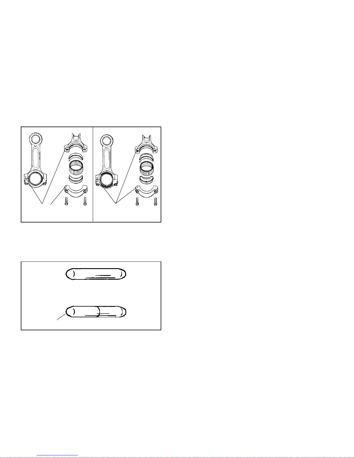
CONNECTING ROD SERVICE
Two cycle engines may be equipped with steel or
aluminum connecting rods. Aluminum connecting rods
use steel liners when needle bearings are utilized.
The connecting rod bolts used are Torx®, size E6. If
torx sockets are not locally available, they can be
purchased through your Tecumseh parts supplier under
part number 670257.
The connecting rod bolts should be tightened alternately
and torqued to proper specification.
All connecting rods have match marks on the connecting
rod and cap. Make certain these match marks are
aligned when assembling.
MATCH MARKS
MATCH MARKS
NEEDLE BEARINGS. Needle bearings may be single
or split row.
Split needles are to be installed with the blunt ends
together and tapered ends outward.
SINGLE NEEDLE
TAPER
SPLIT NEEDLE
Service needles are supplied with a coating to hold
the needles together and make installation easier.
Remove the paper backing on the bearings and wrap
uniformly around the crankshaft journal. Pull the
connecting rod onto the crankshaft journal, place a
few drops of oil onto the needle bearings and install
rod cap. Torque bolts to specification.
42
Page 46
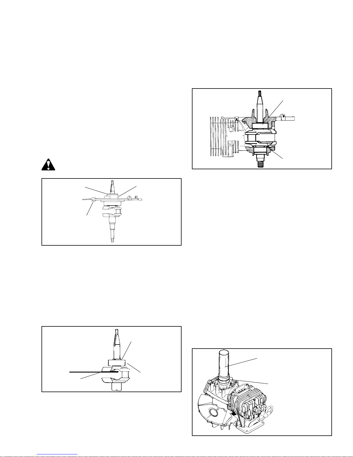
CRANKSHAFT, BEARING AND OIL SEAL SERVICE
Check if crankshaft is bent or otherwise damaged.
Make certain keyways are not worn or damaged and
flywheel taper is clean and in good condition. If taper
or keyways are worn or damaged, replace crankshaft.
Check oil seal contact surfaces on crankshaft for damage
or scratches which would damage oil seal or cause
leaks.
On engines that are equipped with ball bearings, the
crankshaft must be removed with the shroud base.
Before removing shroud base with crankshaft,
disassemble rod cap from rod and remove the piston
from the bore, then remove four (4) shroud base screws
and tap shroud base so base and crankshaft can be
removed together.
To remove crankshaft and bearing from shroud base,
use following procedure:
Using a propane torch, heat the area of shroud
base around the bearing area, until there is enough
expansion to remove the crankshaft and bearing.
HEAT AREA
HEAT AREA
If a ball bearing engine appears to be tight, or if the
flywheel was removed with the use of a knock-off tool,
the ball bearing may be dislodged from shroud base,
forcing the crankshaft lower thrust face against the
cylinder thrust face, To correct this condition, rap sharply
on the P.T.O. end of the crankshaft with rawhide mallet
to provide the clearance between the crankshaft and
cylinder thrust face.
BALL BEARING
MUST HAVE
CLEARANCE
NEEDLE BEARINGS. Caged needle bearings can
be removed and replaced by pressing them in and
out of cylinder using an arbor press.
NOTE: Always press against the lettered side of the
bearing.
SHROUD BASE
To remove the bearing from crankshaft, remove retainer
ring if so equipped, and use a bearing splitter to pull
bearing.
Before installing bearing on crankshaft, clean out the
grooves on the crankshaft where bearing locates and
put Loctite in the groove. Models with the retainer
ring do not require Loctite.
Using a sleeve over the crankshaft, press bearing
into position with arbor press. Make certain crankshaft
counter weight is supported and bearing is pressed
on inner race only.
RETAINER RING
(some Models)
BEARING
SUPPORT
COUNTERWEIGHT
To reinstall crankshaft and ball bearing, heat shroud
base to expand bearing seat and drop ball bearing
into seat of base shroud. Allow to cool.
If the needles fall out of the cage, they can be reinstalled
using grease to hold them in position.
OIL SEALS. It is important on 2 cycle engines that
oil seals are in good condition. A leaky seal will cause
hard starting, erratic running, and possible damage
to internal components due to a lean fuel-oil mixture
caused by extra air getting into the crankcase.
Engines could be equipped with either one piece oil
seals or three pieces consisting of a seal, retainer
and retainer ring; they are not interchangeable.
ONE PIECE SEALS. An oil seal remover tool can be
used for seal removal in some engines. In some cases
it may be necessary to disassemble engine to remove
the oil seals.
Seal driver-protectors are available for most one piece
oil seals. Select the proper tool from the tool list in
Chapter 8. Place the oil seal over the driver protector,
place over crankshaft, and drive into position using
universal driver No. 670272.
DRIVER (No. 670272)
OIL SEAL
DRIVER-PROTECTOR
On outboards only, install shroud base onto cylinder
but before tightening screws, rotate shroud base fully
clockwise. Tighten screws.
43
Page 47
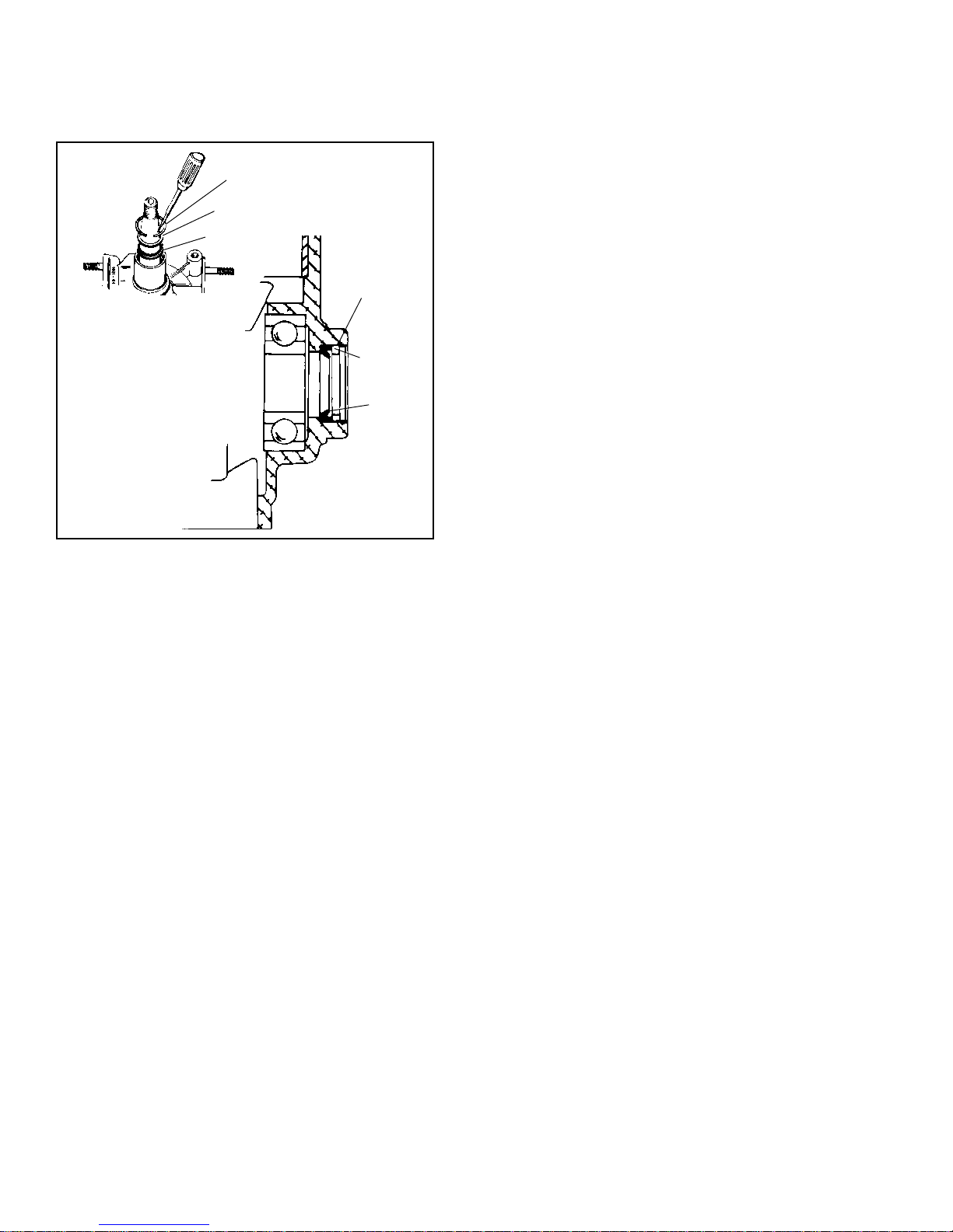
THREE PIECE SEALS. To remove seals, use a sharp
object such as an ice pick to pry out the retainer spring,
then remove the retainer and seal. In some cases it
may be necessary to remove the crankshaft to remove
the oil seals.
RETAINER SPRING
RETAINER
SEAL
RING
RETAINER
SEAL
OUTBOARD SEAL SERVICE. Oil seals on the powertake-off end of the crankshaft are installed in an inverted
(upside down) position to keep water out of engine.
44
Page 48
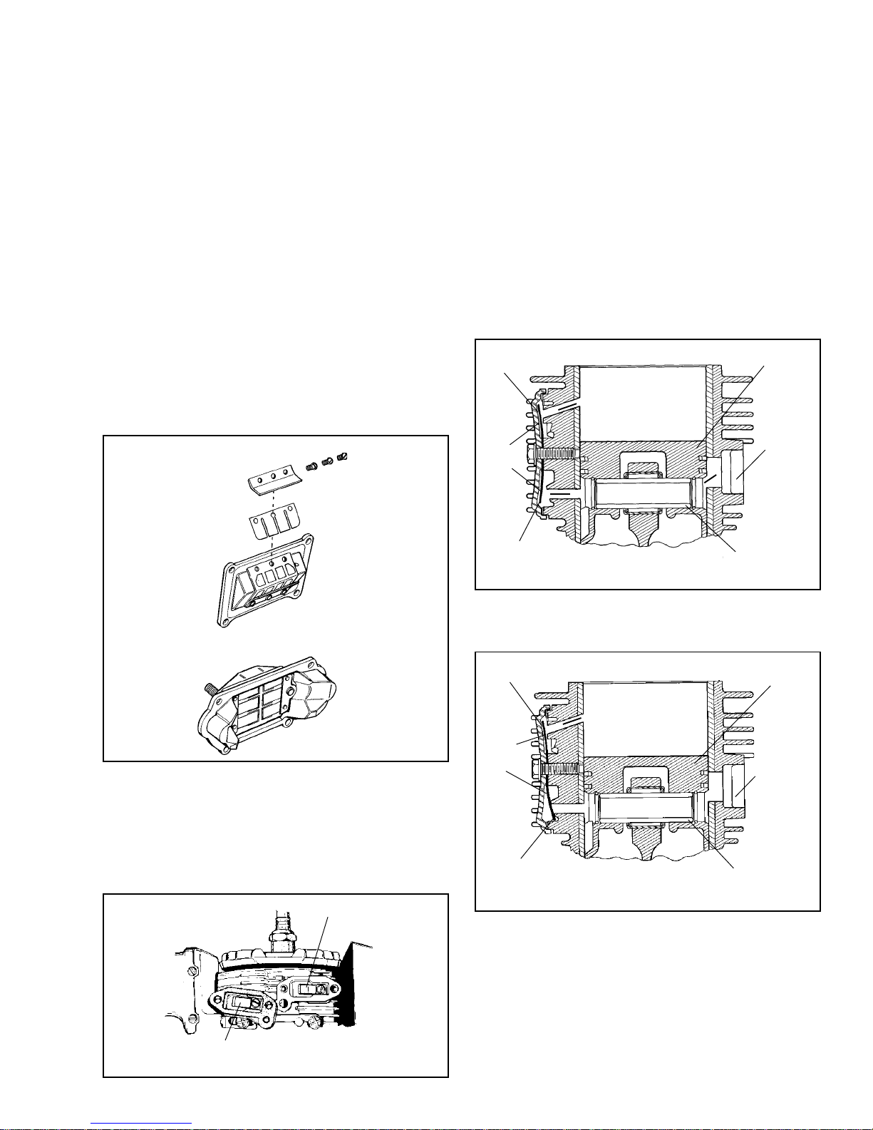
CYLINDERS, REEDS & COMPRESSION RELEASE
CYLINDER & HEAD SERVICE. Check cylinder for
bore damage or scoring. Check for broken or cracked
fins, warped head or head mounting surface. If warped
extensively, (more than .005"/.127 mm) replace. Always
replace head gasket and torque to proper specification.
GASKETS. Replace all gaskets in reassembly and
make sure all sealing surfaces will not leak. A leaking
gasket will cause erratic running, hard starting and
could damage internal components by causing an
imbalance of fuel-oil air mixture.
REED VALVES. Make sure reeds and sealing surfaces
are free of dirt and foreign matter. Check reeds for
seal against sealing surface of the adapter. Reeds
should not bend away from sealing surface more than
.010' (.254 mm).
If the reeds are serviceable, the smooth side of the
reed must locate against the sealing surface. Service
reeds have smudge marks on smooth side. If these
marks are gone, feel for a rough edge and assemble
away from sealing surface.
Replace both reeds If either is defective. When installing
reeds be sure the colored side of the reed faces its
seating surface. If in doubt, feel for a rough edge on
the reed. The rough edge must be installed away from
the seating surface. Assemble reed stop and hold
down and tighten self-tapping screws.
Poor running or lack of power may be caused by a
leaking reed or cover gasket.
AUTOMATIC COMPRESSION RELEASE (SINGLE
REED TYPE).
Cranking compression pressures bleed past reed valve,
through a port, into the piston pin and out the exhaust
port.
REED
OPEN
SINGLE
REED
Ô
Ô
Ô
Ô
Ô
Ô
Ô
Ô
PISTON
EXHAUST
PORT
Ô
AUTOMATIC COMPRESSION RELEASE (DOUBLE
REED TYPE).
Cranking compression pressures bleed past reeds
and into muffler. Once the engine is started, a high
pressure build-up between the reeds forces the reeds
against their seats stopping compression bleed off
and allowing engine to run at full compression.
CYLINDER REED
REED
OPEN
TYPE II
PISTON
PIN
As the engine starts and compression increases, the
reed will be forced against the bottom port, sealing it
and the engine will run under full compression.
REED
OPEN
SINGLE
REED
REED
CLOSED
Ô
Ô
Ô
TYPE II
Ô
Ô
PISTON
EXHAUST
PORT
PISTON
PIN
Install the reed cover (single reed type) with the small
hole towards the spark plug.
COVER REED
TYPE I
45
Page 49
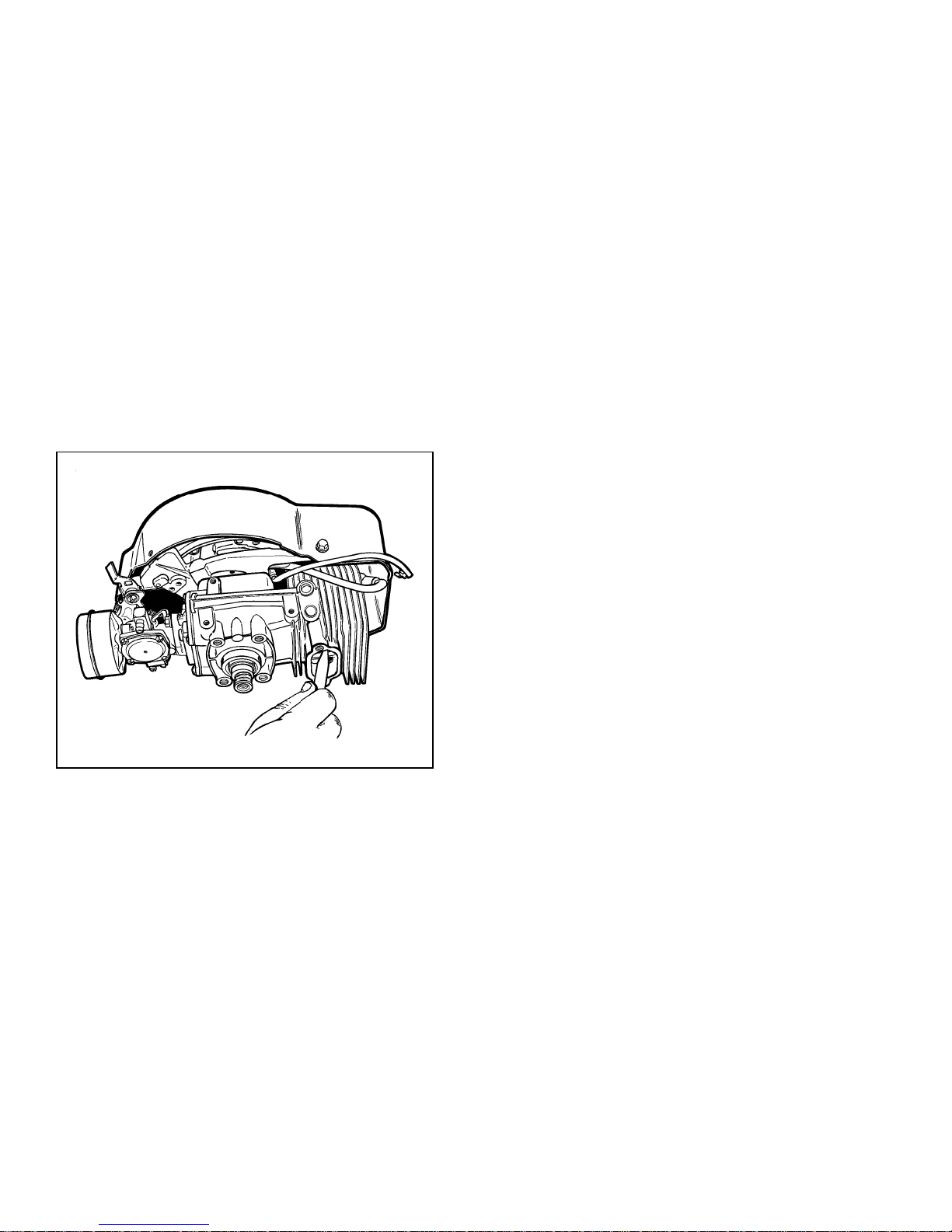
The piston used in the single reed compression release
system has a cutout at the piston pin hole. The piston
must be installed with the cut-out located on the side
facing the compression release.
CYLINDER EXHAUST PORTS. The muffler and cylinder
exhaust ports should be cleaned after each seventyfive (75) to one hundred (100) hours of operation.
It is recommended that the cylinder head be removed
and carbon cleaned from the ports, cylinder head and
top of piston.
CAUTION: Do Not Scratch Metal Surfaces.
With the cylinder head removed, remove any carbon
deposits from the cylinder wall, head, and the top of
the piston. Using a pointed 3/8' wooden dowel or
similar tool, remove the carbon from the exhaust ports.
Being sure to remove all loose carbon particles from
the engine.
NOTE: When cleaning the exhaust ports, check and
clean the compression release passage.
46
Page 50

TROUBLESHOOTING
2 CYCLE ENGINE TROUBLESHOOTING CHART
Cause Remedy and Reference
ENGINE FAILS TO START OR STARTS WITH DIFFICULTY
No fuel in tank Fill tank with clean, fresh fuel with correct oil ratio.
Fuel shut-off valve closed Open valve.
Obstructed fuel line Clean fuel screen and line. If necessary, remove
and clean carburetor.
Tank cap vent obstructed Open vent in fuel tank cap or replace cap.
Water in fuel Drain tank. Clean carburetor and fuel lines. Dry
spark plug points. Fill tank with clean, fresh fuel.
Engine overchoked Close fuel shut-off and pull starter until engine starts.
Reopen fuel shutoff for normal fuel flow immediately
after engine starts.
Improper carburetor adjustment Adjust carburetor.
Loose or defective magneto wiring Check magneto wiring for shorts or grounds; repair
if necessary.
Sheared or incorrect flywheel key or adapter sleeve Replace with correct key or adapter sleeve.
Faulty Magneto Check timing, point gap, and if necessary, overhaul
magneto.
Spark plug fouled Clean and regap spark plug.
Crankcase seals and/or gaskets leaking Replace seals and/or gaskets.
Spark plug porcelain cracked Replace spark plug.
Poor Compression Overhaul engine.
Exhaust ports plugged Clean exhaust ports
ENGINE KNOCKS
Carbon in combustion chamber Remove cylinder head or cylinder and clean carbon
from head and piston.
Loose or worn connecting rod Replace connecting rod.
Loose flywheel Check flywheel key and keyway; replace parts if
Worn cylinder Replace cylinder.
Improper magneto timing Time magneto.
necessary. Tighten flywheel nut to proper torque.
47
Page 51

2 CYCLE ENGINE TROUBLESHOOTING CHART (Cont.)
Cause Remedy
ENGINE MISSES UNDER LOAD
Spark plug fouled Clean and regap spark plug.
Spark plug porcelain cracked Replace spark plug.
Improper spark plug gap Regap spark plug.
Pitted magneto breaker points Clean and dress breaker points. Replace badly
pitted breaker points.
Magneto breaker arm sluggish Clean and lubricate breaker point arm.
Faulty condenser Check condenser on a tester; replace if defective
(see test instrument instructions and specifications).
Improper carburetor adjustment Adjust carburetor.
Reed fouled or sluggish Clean or replace reed.
Crankcase seal leak Replace worn crankcase seals.
ENGINE LACKS POWER
Choke partially closed Open choke.
Blown head gasket Replace head gasket.
Improper carburetor adjustment Adjust carburetor.
Improper or partially sheared flywheel key or Replace with new correct key or sleeve.
adapter sleeve.
Magneto improperly timed Time magneto.
Worn piston or rings Replace piston or rings.
Air cleaner clogged Clean air cleaner.
Reed fouled or sluggish Clean or replace reed.
Improper amount of oil in fuel mixture Drain tank; fill with correct mixture (See engine
decal).
Carburetor improperly adjusted Adjust carburetor.
Crankcase seals leaking Replace worn crankcase seals
ENGINE OVERHEATS
Engine improperly timed Time engine.
Improper or partially sheared flywheel key or Replace with new correct key or sleeve.
adapter sleeve.
Air flow obstructed Remove any obstructions from air passages in
Cooling fins clogged Clean cooling fins.
48
shrouds.
Page 52
2 CYCLE ENGINE TROUBLESHOOTING CHART (Cont.)
Cause Remedy
ENGINE OVERHEATS (continued)
Excessive load on engine Check operation of associated equipment. Reduce
excessive load.
Carbon in combustion chamber Remove cylinder head or cylinder and clean carbon
from head and piston.
Improper amount of oil in fuel mixture Drain tank; fill with correct mixture.
ENGINE SURGES OR RUNS UNEVENLY
Fuel tank cap vent hole clogged Open vent hole.
Crankcase air leak Inspect and replace gasket or seal.
Governor parts sticking or binding Clean, and if necessary repair governor parts.
Carburetor throttle linkage or throttle shaft and/or Clean, lubricate, or adjust linkage and deburr throttle
butterfly binding or sticking shaft or butterfly.
ENGINE VIBRATES EXCESSIVELY
Engine not securely mounted Tighten loose mounting bolts (See equipment
instructions).
Bent crankshaft Replace crankshaft.
Driven equipment out of balance Recheck driven equipment.
Piston installed incorrectly. Engines with wrist Install piston correctly.
pin offset.
49
Page 53
SPECIFICATIONS
ENGINE TYPE NUMBER AND LETTER REFERENCE
Tecumseh has used two different methods of identifying 2 cycle engines.
The first method was used until the mid 1980's using the base model number with a type number. The type
number was used to identify variations for the OEM's specific needs.
The second method was put in place to standardize 2 cycle and 4 cycle engine identification. The type
number has now become the specification number, which is preceded by the engine model. Example: AV520
Tecumseh type numbers are stamped into the blower housing, or are located on a nameplate or tag on the
engine.
Model and Specification numbers are either stamped into the blower housing, or located on a decal on the
side of the blower housing.
Column
TYPE NO. No.
Vertical Crankshaft Engines
638 thru 638-100 6
639 thru 639-13A 13
640-02 thru 640-06B 21
640-07 thru 640-21-A 22
640-23 36
641 thru 641-14 11
642-01,A 9A
642-02, A thru G 9A
642-02E, F 9B
642-03, A, B 9A
642-04, A, B, C 9A
642-05, A, B 9A
642-06, A 9A
642-07, A, B 9A
642-07C 9B
642-08 9B
642-08A, B, C 9A
642-09 thru 642-14 9A
642-13 thru 14C 9B
642-15 thru 642-23 9B
642-24 thru 642-33 9C
642-35 34
643-01, A, 03, A 10A
643-03B, C 10B
643-04, 05A 10A
643-05B 10B
643-13,14 10A
643-14A, B, C 10B
643-15 10A
643-15A thru 643-32 10B
643-32A 32
643-33 33
643-34 33
643-35,A,B 37
650 14
653-01 thru 653-05 31
653-07 thru 653-10 38
660-11 thru 660-38 18
660-39,A 39
660-40 40
661-01 thru 661-29 29
661-30 thru 661-45 41
662-02 42
662-623A 42
670-01 thru 670-109 8
Horizontal Crankshaft Engines
1398 thru 1399 11
1400 11
1401 thru 1401F 16
1401G, H 17
Column
TYPE NO. No.
1401J 27
1402 and 1402B 7
1425 7
1430A 7
1432, A 7
1440, A, B, C, D 1
1442, A, B, 7
1444, A 7
1448 thru 1450 16
1450A, A, B, C, D, E 16
1450F 17
1454, A 1
1459 7
1460, A, B ,C, D, E, F 1
1462 1
1464, A, B 12
1465 1
1466, A 16
1471, A, B 5
1472, A, B, C 12
1473, A, B 1
1474 12
1475 thru 1476 1
1479 7
1482, A 16
1483 16
1484, A, B, C, D 3
1485 7
1486 4
1488, A, B, C, D 1
1489 thru 1490B 3
1491 12
1493, A 7
1494 and 1495A 2
1496 7
1497 1
1498 5
1499 16
1500 5
1501,A, B, C, D, E,F,G 1
1503, A, B, C, D 12
1506 16
1506B 17
1507 16
1508 7
1509 3
1510 12
1511 3
1512, A 2
1513 12
1515 thru 1516C 3
1517 5
1518 4
Column
TYPE NO. No.
Horizontal Crankshaft EnginesHorizontal Crankshaft Engines
1519 thru 1521 1
1522 12
1523 1
1524 2
1525A 16
1527 3
1528,A,B 1
1529, A, B 3
1530, A, B 1
1531 3
1534A 17
1535B 3
1536 12
1537 1
1538 thru 1541A 12
1542 5
1543 thru 1546 1
1547 3
1549 3
1550A 15
1551 16
1552 20
1553 16
1554,A 3
1555 and 1556 16
1557 thru 1560 15
1561 19
1562 thru 1571 23
1572 2
1573 3
1574 thru 1577 23
1575 24
1578 25
1581 thru 1582A 23
1583 thru 1599A 26
1600 thru 1617 28
1618 thru 1619 43
1620 30
1622 thru 1623A 42
1624 thru 1642 35
MODEL PAGE NO.
AV520 61
AV600 61
AH600 61
HSK600 61
TVS600 61
50
Page 54
SEARS CRAFTSMAN CROSS REFERENCE
Craftsman
Vertical Crankshaft Engines
Craftsman No. Column No.
200.183112 6
200.183122 6
200.193132 6
200.193142 6
200.193152 7
200.193162 7
200.203112 8
200.203172 8
200.203182 8
200.203192 8
200.213112 8
200.213122 8
200.213132 8
200.223112 41
200.233112 41
200.243112 8
200.283012 8
200.2131128 31
200.2132228 29
Craftsman
Horizontal Crankshaft Engines
Craftsman No. Column No.
200.503111 16
200.583111 16
200.593121 16
200.602112 35
200.613111 16
200.633111 35
200.643121 35
200.672102 26
200.682102 26
200.692112 26
200.692122 26
200.692132 26
200.701001 AH600-1665N
200.711001 HSK600-1665P
200.731001 HSK600-1686R
200.731011 HSK600-1687R
143.943071 HSK600-1687S
143.953071 HSK600-1700S
143.973071 HSK600-1705S
143.973091 HSK600-1700S
143.983071 HSK600-1708T
143.993071 HSK600-1712T
51
Page 55

TABLE OF SPECIFICATIONS
Reference Column 1 2 3 4 5
U.S. Metric U.S. Metric U.S. Metric U.S. Metric U.S. Metric
mm mm mm mm mm
Bore 2.093 53.162 2.093 53.162 2.093 53.162 2.093 53.162 2.093 53.162
2.094 53.188 2.094 53.188 2.094 53.188 2.094 53.188 2.094 53.188
Stroke 1.250 31.75 1.410 35.814 1.410 35.814 1.410 35.814 1.410 35.814
Cu. In. Displacement 4.40 72.1 4.80 78.7 4.80 78.7 4.80 78.7 4.80 78.7
(in3) (cc)
Point Gap .017 .432 .017 .432 .017 .432 .017 .432 .017 .432
Timing .122 3.098 .100 2.54 .135 3.429 .100 2.54 .135 3.429
B.T.D.C.
Spark Plug Gap .030 .762 .030 .762 .030 .762 .030 .762 .030 .762
Piston Ring .007 .178 .007 .178 .006 .15 .006 .15 .006 .15
End Gap .017 .432 .017 .432 .011 .28 .014 .35 .011 .28
Piston 2.0870 53.01 2.0870 53.01 2.0875 53.023 2.0875 53.023 2.0875 53.023
Diameter 2.0880 53.035 2.0880 53.035 2.0885 53.048 2.0885 53.048 2.0885 53.048
(Top) .0655 1.664 .0655 1.664 .0655 1.664 .0975 1.664 .0655 1.664
Piston Ring
Groove Width
(Bot.) .0655 1.664 .0655 1.664 .0655 1.664 .0965 1.664 .0655 1.664
Piston Ring .0615 1.562 .0615 1.562 .0615 1.562 .0925 2.35 .0615 1.562
Width .0625 1.587 .0625 1.587 .0625 1.587 .0935 2.375 .0625 1.587
Piston Pin .4997 12.692 .4997 12.692 .4997 12.692 .3750 9.525 .4997 12.693
Diameter .4999 12.697 .4999 12.697 .4999 12.697 .3751 9.528 .4999 12.697
Crank Pin Journal .5611 14.252 .5614 14.260 .5614 14.260 .6857 17.417 .5611 14.252
Diameter .5618 14.270 .5621 14.277 .5621 14.277 .6865 17.437 .5618 14.270
Crankshaft .6691 16.995 .6691 16.995 .6691 16.995 .6691 16.995 .6691 16.995
P.T.O. Side .6695 17.005 .6695 17.005 .6695 17.005 .6695 17.005 .6695 17.005
Main Brg. Dia.
Crankshaft .6691 16.995 .6691 16.995 .6691 16.995 .6691 16.995 .6691 16.995
Magneto Side .6695 17.005 .6695 17.005 .6695 17.005 .6695 17.005 .6695 17.005
Main Brg. Dia.
Crankshaft None None None None None None None None None None
End Play
.0665 1.689 .0665 1.689 .0665 1.689 .0985 1.689 .0665 1.689
.0645 1.638 .0645 1.638 .0645 1.638 .0955 1.638 .0645 1.638
52
Page 56

TABLE OF SPECIFICATIONS
Reference Column 6 7 8 9A 9B
U.S. Metric U.S. Metric U.S. Metric U.S. Metric U.S. Metric
mm mm mm mm mm
Bore 2.093 53.162 2.093 53.162 2.093 53.162 2.093 53.162 2.093 53.162
2.094 53.188 2.094 53.188 2.094 53.188 2.094 53.188 2.094 53.188
Stroke 1.500 38.1 1.500 38.1 1.500 38.1 1.500 38.1 1.500 38.1
Cu. In. Displacement 5.20 85.2 5.20 85.2 5.20 85.2 5.20 85.2 5.20 85.2
(in3) (cc)
Point Gap .018 .457 .017 .432 .020 .508 .018 .457 .020 .508
Timing .100 2.54 .185 4.699 .070 1.778 .100 2.54 .085 2.159
B.T.D.C. See Note 1 See Note 2
Spark Plug Gap .030 .762 .030 .762 .030 .762 .030 .762 .030 .762
Piston Ring .006 .153 .007 .178 .006 .153 .007 .178 .006 .153
End Gap .014 .356 .017 .432 .016 .406 .017 .432 .016 .406
Piston 2.0870 53.01 2.0870 53.01 2.0870 53.01 2.0870 53.01 2.0870 53.01
Diameter 2.0880 53.035 2.0880 53.035 2.0880 53.035 2.0880 53.035 2.0880 53.035
(Top) .0975 1.664 .0655 1.664 .0655 1.664 .0655 1.664 .0655 1.664
Piston Ring
Groove Width
(Bot.) .0965 1.664 .0655 1.664 .0655 1.664 .0655 1.664 .0655 1.664
Piston Ring .0925 2.35 .0615 1.562 .0615 1.562 .0615 1.562 .0615 1.562
Width .0935 2.375 .0625 1.587 .0625 1.587 .0625 1.587 .0625 1.587
Piston Pin .3750 9.525 .4997 12.692 .4997 12.692 .4997 12.692 .4997 12.692
Diameter .3751 9.528 .4999 12.697 .4999 12.697 .4999 12.697 .4999 12.697
Crank Pin Journal .6857 17.417 .5611 14.252 .8442 21.443 .6857 17.417 .8442 21.443
Diameter .6865 17.437 .5618 14.270 .8450 21.463 .6865 17.437 .8450 21.463
Crankshaft .8745 22.212 .6690 16.993 .9998 25.349 .8745 22.212 .9998 25.349
P.T.O. Side .8750 22.225 .6694 17.003 1.0003 25.408 .8750 22.225 1.0003 25.408
Main Brg. Dia.
Crankshaft Ball Bearing
Magneto Side .7495 19.037 .6690 16.993 .6691 16.995 .7495 19.037 .7498 19.045
Main Brg. Dia. .7500 19.05 .6694 17.003 .6695 17.005 .7500 19.05 .7503 19.058
Crankshaft .003 .076 None None None None .003 .076 .003 .076
End Play .016 .406 .016 .406 .016 .406
.0985 1.689 .0665 1.689 .0665 1.689 .0665 1.689 .0665 1.689
.0955 1.638 .0645 1.638 .0645 1.638 .0645 1.638 .0645 1.638
See Note A
NOTE 1: 642-08, 14A, 14B B.T.D.C. = .110
642-16D, 19A, 20A, 21, 22 B.T.D.C. = .078
NOTE 2: 642-24, 26, 29 B.T.D.C. = .087
NOTE A: Needle Bearing
.7498
.7503
53
Page 57

TABLE OF SPECIFICATIONS
Reference Column 9C 10A 10B 11 12
U.S. Metric U.S. Metric U.S. Metric U.S. Metric U.S. Metric
mm mm mm mm mm
Bore 2.093 53.162 2.093 53.162 2.093 53.162 2.093 53.162 2.093 53.162
2.094 53.188 2.094 53.188 2.094 53.188 2.094 53.188 2.094 53.188
Stroke 1.500 38.1 1.750 44.45 1.750 44.45 1.750 44.45 1.410 35.814
Cu.In. Displacement 5.20 85.2 6.00 98.3 6.00 98.3 6.00 98.3 4.80 78.7
(in3) (cc)
Point Gap .020 .508 .018 .457 .020 .508 .018 .457 .017 .432
See Note 4
Timing .078 1.98 .090 2.286 .087 2.21 .100 2.54 .135 3.429
B.T.D.C. See Note 2 See Note 3
Spark Plug Gap .030 .762 .030 .762 .030 .762 .030 .762 .030 .762
Piston RIng .006 .152 .007 .178 .006 .152 .006 .152 .007 .178
End Gap .016 .406 .017 .432 .016 .406 .014 .356 .017 .432
Piston 2.0870 53.01 2.0870 53.01 2.0870 53.01 2.0873 53.017 2.0870 53.01
Diameter 2.0880 53.035 2.0880 53.035 2.0880 53.035 2.0883 53.043 2.0880 53.035
(Top) .0655 1.664 .0655 1.664 .0665 1.689 .0655 1.664 .0655 1.664
Piston Ring
Groove Width
(Bot.) .0655 1.664 .0655 1.664 .0655 1.664 .0965 2.451 .0655 1.664
Piston Ring .0615 1.562 .0615 1.562 .0615 1.562 .0615 1.562 .0625 1.587
Width .0625 1.587 .0625 1.587 .0625 1.587 .0935 2.375 .0925 2.349
Piston Pin .4997 12.692 .4997 12.692 .4997 12.692 .4997 12.692 .4997 12.692
Diameter .4999 12.697 .4999 12.697 .4999 12.697 .4999 12.697 .4999 12.697
Crank Pin Journal .8442 21.443 .6857 12.417 .8442 21.443 .6857 17.417 .5614 14.26
Diameter .8450 21.463 .6865 17.437 .8450 21.463 .6865 17.437 .5621 14.277
Crankshaft .9998 25.395 .8745 22.212 .9998 25.395 .8745 22.212 .6691 16.995
P.T.O. Side 1.0003 25.408 .8750 22.225 1.0003 25.408 .8750 22.225 .6695 17.005
Main Brg. Dia.
Crankshaft .6691 16.995 .7495 19.037 .7498 19.045 .7495 10.037 .6691 16.995
Magneto Side .6695 17.005 .7500 19.05 .7503 19.058 .7500 19.05 .6695 17.005
Main Brg. Dia.
Crankshaft None None .003 .076 .003 .076 .003 .076 None None
End Play .016 .406 .016 .406 .016 .406
.0665 1.689 .0665 1.689 .0975 2.477 .0985 2.413 .0665 1.689
.0645 1.638 .0645 1.638 .0645 1.638 .0955 2.426 .0645 1.638
NOTE 2: 642-24, 26, 29 B.T.D.C. = .087
NOTE 3: 643-13 B.T.D.C. = .095
NOTE 4: 643-93A, 05A, 13, 14 = .020
54
Page 58

TABLE OF SPECIFICATIONS
Reference Column 13 14 15 16 17
U.S. Metric U.S. Metric U.S. Metric U.S. Metric U.S. Metric
mm mm mm mm mm
Bore 2.375 60.33 2.093 53.162 2.4375 61.913 2.093 53.162 2.093 53.162
2.376 60.35 2.094 53.188 2.4385 61.938 2.094 53.188 2.094 53.188
Stroke 1.680 42.672 1.500 38.1 1.750 44.45 1.500 38.1 1.500 38.1
Cu. In. Displacement 7.50 122.9 5.20 85.2 8.17 133.9 5.20 85.2 5.20 85.2
(in3) (cc)
Point Gap .020 .508 .018 .457 .018 .457 .017 .432 .017 .432
Timing .095 2.413 .100 2.54 .100 2.54 .110 2.794 .110 2.794
B.T.D.C.
Spark Plug Gap .030 .762 .030 .762 .030 .762 .030 .762 .030 .762
Piston Ring .005 .127 .006 .152 .007 .178 .006 .152 .006 .152
End Gap .013 .330 .014 .356 .017 .432 .016 .406 .016 .406
Piston 2.3685 60.16 2.0870 53.01 2.4302 61.727 2.0875 53.023 2.0880 53.035
Diameter 2.3695 60.185 2.0880 53.035 2.4312 61.753 2.0885 53.048 2.0890 53.061
(Top) .0655 1.664 .0975 1.664 .0655 1.664 .0645 1.638 .0645 1.638
Piston Ring
Groove Width
(Bot.) .0655 1.664 .0965 2.451 .0655 1.664 .0655 1.664 .0655 1.664
Piston Ring .0615 1.562 .0615 1.562 .0625 1.587 .0615 1.562 .0615 1.562
Width .0625 1.587 .0935 2.375 .0925 2.35 .0625 1.587 .0625 1.587
Piston Pin .4997 12.692 .3750 9.525 .4997 12.692 .3750 9.525 .4997 12.692
Diameter .4999 12.697 .3751 9.528 .4999 12.698 .3751 9.528 .4999 12.697
Crank Pin Journal .6259 15.898 .6957 17.671 .6259 15.898 .6857 17.417 .6857 17.417
Diameter .6266 15.916 .6865 17.427 .6266 15.916 .6868 17.445 .6865 17.445
Crankshaft .8650 21.971 .8745 22.12 .6691 16.995 .6691 16.995 .9998 25.349
P.T.O. Side .8850 22.479 .8750 22.225 .6695 17.001 .6695 17.001 1.0003 25.408
Main Brg. Dia.
Crankshaft .7495 19.037 .7495 19.037 .7495 19.037 .7495 19.037 .7495 19.037
Magneto Side .7503 19.058 .7500 19.058 .7500 19.058 .7500 19.058 .7500 19.058
Main Brg. Dia.
Crankshaft None None .003 .076 None None None None None None
End Play .016 .406
.0665 1.664 .0985 1.689 .0665 1.664 .0655 1.664 .0655 1.664
.0645 1.638 .0955 2.426 .0645 1.638 .0645 1.638 .0645 1.638
55
Page 59

TABLE OF SPECIFICATIONS
Reference Column 18 19 20 21 22
U.S. Metric U.S. Metric U.S. Metric U.S. Metric U.S. Metric
mm mm mm mm mm
Bore 2.093 53.162 2.093 53.162 2.093 53.162 2.4375 61.913 2.437 61.900
2.094 53.188 2.094 53.188 2.094 53.188 2.4385 61.938 2.438 61.925
Stroke 1.750 44.45 1.410 35.814 1.250 31.75 1.750 44.45 1.750 44.45
Cu. In. Displacement 6.02 98.7 4.80 78.7 4.40 72.1 8.17 133.9 8.17 133.9
(in3) (cc)
Point Gap .020 .508 .017 .432 .017 .432 .020 .508 .020 .508
Timing .070 1.778 .100 2.54 .122 3.099 .118 2.997 .115 2.921
B.T.D.C.
Spark Plug Gap .030 .762 .030 .762 .030 .762 .030 .762 .030 .762
Piston Ring .006 .152 .007 .178 .007 .178 .007 .178 .007 .178
End Gap .016 .406 .017 .432 .017 .432 .017 .432 .017 .432
Piston 2.0870 53.01 2.0870 53.01 2.0870 53.01 2.4302 61.727 2.4302 61.727
Diameter 2.0880 53.035 2.0880 53.035 2.0880 53.035 2.4312 61.753 2.4312 61.753
(Top) .0645 1.638 .0645 1.638 .0655 1.664 .0655 1.664 .0655 1.664
Piston Ring
Groove Width
(Bot.) .0655 1.664 .0655 1.664 .0655 1.664 .0655 1.664 .0655 1.664
Piston Ring .0615 1.562 .0615 1.562 .0615 1.562 .0615 1.562 .0615 1.562
Width .0625 1.587 .0625 1.587 .0625 1.587 .0625 1.587 .0625 1.587
Piston Pin .4997 12.692 .4997 12.692 .4997 12.692 .4997 12.692 .4997 12.692
Diameter .4999 12.675 .4999 12.675 .4999 12.675 .4999 12.675 .4999 12.675
Crank Pin Journal .8442 21.443 .5614 14.26 .5611 14.252 .6259 15.898 .6919 17.574
Diameter .8450 21.463 .5621 14.277 .5618 14.270 .6266 15.916 .6927 17.595
Crankshaft .6691 16.995 .6691 16.995 .6691 16.995 .6691 16.995 .6691 16.995
P.T.O. Side .6695 17.005 .6695 17.005 .6695 17.005 .6695 17.005 .6695 17.005
Main Brg. Dia.
Crankshaft Ball Bearing
Magneto Side .9998 25.395 .6691 16.995 .6691 16.995 .8745 22.212 .8748 22.223
Main Brg. Dia. 1.0003 25.408 .6695 17.005 .6695 17.005 .8750 22.225 .8753 22.233
Crankshaft None None None None None None None None None None
End Play
.0655 1.664 .0655 1.664 .0665 1.689 .0665 1.689 .0665 1.689
.0645 1.638 .0645 1.638 .0645 1.638 .0645 1.638 .0645 1.638
See Note A
NOTE A: Needle Bearing
* Does not apply to units with Solid State Ignition.
.7498
.7503
56
Page 60

TABLE OF SPECIFICATIONS
Reference Column 23 24 25 26 27
U.S. Metric U.S. Metric U.S. Metric U.S. Metric U.S. Metric
mm mm mm mm mm
Bore 2.093 53.162 2.093 53.162 2.093 53.162 2.093 53.162 2.093 53.162
2.094 53.188 2.094 53.188 2.094 53.188 2.094 53.188 2.094 53.188
Stroke .1500 38.1 1.410 35.814 .1410 35.814 1.500 38.1 1.500 38.1
Cu. In. Displacement 5.20 85.2 4.80 78.7 4.80 78.7 5.20 85.2 5.20 85.2
(in3) (cc)
Point Gap .017 .432 .017 .432 .020 .508 .020 .508 .017 .432
Timing .110 2.794 .135 3.429 Fixed Fixed .062 1.575 .100 2.54
B.T.D.C.
Spark Plug Gap .030 .762 .030 .762 .030 .762 .030 .762 .030 .762
Piston Ring .006 .152 .007 .178 .007 .178 .006 .152 .006 .152
End Gap .016 .406 .017 .432 .017 .432 .016 .406 .016 .406
Piston 2.0870 53.01 2.0870 53.01 2.0870 53.01 2.0870 53.01 2.0875 53.01
Diameter 2.0880 53.035 2.0880 53.035 2.0880 53.035 2.0880 53.035 2.0885 53.035
(Top) .0655 1.664 .0655 1.664 .0655 1.664 .0655 1.664 .0655 1.664
Piston Ring
Groove Width
(Bot.) .0655 1.664 .0655 1.664 .0655 1.664 .0655 1.664 .0655 1.664
Piston Ring .0615 1.562 .0615 1.562 .0615 1.562 .0615 1.562 .0615 1.562
Width .0625 1.587 .0625 1.587 .0625 1.587 .0625 1.587 .0625 1.587
Piston Pin .4997 12.692 .4997 12.692 .4997 12.692 .4997 12.692 .4997 12.692
Diameter .4999 12.697 .4999 12.697 .4999 12.697 .4999 12.697 .4999 12.697
Crank Pin Journal .6919 17.574 .5614 14.26 .5614 14.26 .6919 17.574 .6922 17.582
Diameter .6927 17.595 .5621 14.277 .5621 14.277 .6927 17.595 .6927 17.595
Crankshaft .6691 16.995 .6691 16.995 .6691 16.995 .7498 19.045 .6691 16.995
P.T.O. Side .6695 17.005 .6695 17.005 .6695 17.005 .7503 19.058 .6695 17.005
Main Brg. Dia.
Crankshaft .7498 19.045 .6691 17.551 .6691 17.551 .6691 17.551 .7498 19.045
Magneto Side .7503 19.058 .6695 17.005 .6695 17.005 .6695 17.005 .7503 19.058
Main Brg. Dia.
Crankshaft None None None None None None None None .003 .076
End Play .016 .406
.0665 1.689 .0665 1.689 .0665 1.689 .0665 1.689 .0665 1.689
.0645 1.638 .0645 1.638 .0645 1.638 .0645 1.638 .0645 1.638
57
Page 61

TABLE OF SPECIFICATIONS
Reference Column 28 29 30 31 32
U.S. Metric U.S. Metric U.S. Metric U.S. Metric U.S. Metric
mm mm mm mm mm
Bore 2.093 53.162 2.093 53.162 2.093 53.162 2.093 53.162 2.093 53.162
2.094 53.188 2.094 53.188 2.094 53.188 2.094 53.188 2.094 53.188
Stroke 1.500 38.1 1.746 44.348 1.746 44.348 1.500 38.1 1.746 44.348
Cu. In. Displacement 5.20 85.2 6.0 98.3 6.0 98.3 5.20 85.2 6.0 98.3
(in3) (cc)
Point Gap .020 .508 .020* .508 .020 .508 .020 .508 .020 .508
Timing Ext. Ext. Ext. Ext. .052 1.321 Ext. Ext. .088 2.235
B.T.D.C. Ignition Ignition Ignition Ignition Igniton Ignition
Spark Plug Gap .030 .762 .030 .762 .030 .762 .030 .762 .030 .762
Piston Ring .006 .152 .007 .178 .006 .152 .006 .152 .006 .152
End Gap .016 .152 .017 .432 .016 .152 .016 .152 .016 .152
Piston 2.0875 53.023 2.0865 52.997 2.0875 53.023 2.0865 52.997 2.0865 52.997
Diameter 2.0885 53.048 2.0875 53.023 2.0885 53.048 2.0875 53.028 2.0875 53.023
(Top) .0655 1.664 .0655 1.664 .0655 1.664 .0655 1.664 .0655 1.664
Piston Ring
Groove Width
(Bot.) .0655 1.664 .0655 1.664 .0655 1.664 .0655 1.664 .0655 1.664
Piston Ring .0615 1.652 .0615 1.652 .0615 1.652 .0615 1.652 .0615 1.652
Width .06251 .587 .0625 1.587 .0625 1.587 .0625 1.587 .0625 1.587
Piston Pin .4997 12.692 .4997 12.692 .4997 12.692 .4997 12.692 .4997 12.692
Diameter .4999 12.697 .4999 12.697 .4999 12.697 .4999 12.697 .4999 12.697
Crank Pin Journal .6922 17.582 .8113 20.607 .8113 20.607 .8113 20.607 .8445 21.450
Diameter .6927 17.595 .8118 20.620 .8118 20.620 .8118 20.620 .8450 21.463
Crankshaft .7498 19.045 .9998 25.395 .7498 19.045 .9998 25.395 .9998 25.395
P.T.O. Side .7503 19.058 1.0003 25.408 .7503 19.058 1.0003 25.408 1.0003 25.408
Main Brg. Dia.
Crankshaft .6695 17.005 .6695 17.005 .6695 17.005 .7498 17.005 .6695 17.005
Magneto Side .6699 17.015 .6699 17.015 .6699 17.015 .7503 17.015 .6699 17.015
Main Brg. Dia.
Crankshaft None None None None None None None None .003 .076
End Play .016 .406
.0665 1.689 .0665 1.689 .0665 1.689 .0665 1.689 .0665 1.689
.0645 1.638 .0645 1.638 .0645 1.638 .0645 1.638 .0645 1.638
*Does not apply to units with Solid State Ignition.
58
Page 62

TABLE OF SPECIFICATIONS
Reference Column 33 34 35 36 37
U.S. Metric U.S. Metric U.S. Metric U.S. Metric U.S. Metric
mm mm mm mm mm
Bore 2.093 53.162 2.093 53.162 2.093 53.162 2.437 61.90 2.093 53.162
2.094 53.188 2.094 53.188 2.094 53.188 2.438 66.925 2.094 53.188
Stroke 1.746 44.348 1.746 44.348 1.500 38.1 1.746 44.348 1.750 44.45
Cu. In. Displacement 6.0 98.3 6.0 98.3 5.20 85.2 6.0 98.3 6.0 98.3
(in3) (cc)
Point Gap .020 .508 .020 .508 *.020 .508 .020 .508 .020 .508
Timing .073 1.854 .078 1.854 Ext. Ext. .112 2.845 .088 2.235
B.T.D.C. Ignition Ignition
Spark Plug Gap .030 .762 .030 .762 .030 .762 .030 .762 .030 .762
Piston Ring .006 .152 .006 .152 .006 .152 .007 .178 .006 .152
End Gap .016 .406 .016 .406 .016 .406 .017 .432 .016 .406
Piston 2.0865 52.997 2.0865 52.997 2.0882 53.04 2.4307 61.74 2.0880 53.035
Diameter 2.0875 53.023 2.0875 53.023 2.0887 53.05 2.4317 61.765 2.0885 53.049
(Top) .0655 1.664 .0655 1.664 .0655 1.664 .0655 1.664 .0655 1.664
Piston Ring
Groove Width
(Bot.) .0655 1.664 .0655 1.664 .0655 1.664 .0655 1.664 .0655 1.664
Piston Ring .0615 1.562 .0615 1.562 .0615 1.562 .0615 1.562 .0615 1.562
Width .0625 1.587 .0625 1.587 .0625 1.587 .0625 1.587 .0625 1.587
Piston Pin .4997 12.692 .4997 12.692 .4997 12.692 .4997 12.692 .4997 12.692
Diameter .4999 12.698 .4999 12.698 .4999 12.698 .4999 12.698 .4999 12.698
Crank Pin Journal .8113 20.607 .8445 21.450 .8113 20.607 .6922 17.582 .8445 21.450
Diameter .8118 20.620 .8450 21.463 .8118 20.620 .6927 17.595 .8450 21.463
Crankshaft .9998 25.395 .9993 25.295 .7498 19.045 .6695 17.005 .9998 25.395
P.T.O. Side 1.0003 25.408 1.0003 25.408 .7503 19.058 .6699 17.015 1.0003 25.408
Main Brg. Dia.
Crankshaft .6695 17.005 .6695 17.005 .6695 17.005 .8748 22.22 .6695 17.005
Magneto Side .6699 17.015 .6699 17.015 .6699 17.015 .8753 22.233 .6699 17.015
Main Brg. Dia.
Crankshaft .003 .076 .003 .076 None None None None .003 .076
End Play .016 .406 .016 .406 .016 .406
.0665 1.689 .0665 1.689 .0665 1.689 .0665 1.689 .0665 1.689
.0645 1.638 .0645 1.638 .0645 1.638 .0645 1.638 .0645 1.638
59
Page 63

TABLE OF SPECIFICATIONS
Reference Column 38 39 40 41 42
U.S. Metric U.S. Metric U.S. Metric U.S. Metric U.S. Metric
mm mm mm mm mm
Bore 2.093 53.162 2.093 53.162 2.093 53.162 2.093 53.162 2.093 53.162
2.094 53.188 2.094 53.188 2.094 53.188 2.094 53.188 2.094 53.188
Stroke 1.828 46.431 1.500 38.1 1.828 46.431 1.746 44.348 1.500 38.1
Cu. In. Displacement 6.0 98.3 5.20 85.2 6.0 98.3 6.0 98.3 5.20 85.2
(in3) (cc)
Point Gap * .020 .508 .020 .508 * .020 .508
Timing Ext. Ext. .088 2.235 .070 1.778 Ext. Ext. Ext. Ext.
B.T.D.C. Ignition Ignition Ignition Ignition Ignition Ignition
Spark Plug Gap .030 .762 .030 .762 .030 .762 .030 .762 .030 .762
Piston Ring .006 .152 .006 .152 .006 .152 .006 .152 .006 .152
End Gap .016 .406 .016 .406 .016 .406 .016 .406 .016 .406
Piston 2.0880 53.035 2.0880 53.035 2.0880 53.035 2.0880 53.035 2.0880 53.035
Diameter 2.0885 53.049 2.0885 53.049 2.0885 53.049 2.0885 53.049 2.0885 53.049
(Top) .0655 1.664 .0655 1.664 .0655 1.664 .0655 1.664 .0655 1.664
Piston Ring
Groove Width
(Bot.) .0655 1.664 .0655 1.664 .0655 1.664 .0655 1.664 .0655 1.664
Piston Ring .0615 1.562 .0615 1.562 .0615 1.562 .0615 1.562 .0615 1.562
Width .0625 1.587 .0625 1.587 .0625 1.587 .0625 1.587 .0625 1.587
Piston Pin .4997 12.692 .4997 12.692 .4997 12.692 .4997 12.692 .4997 12.692
Diameter .4999 12.697 .4999 12.697 .4999 12.697 .4999 12.697 .4999 12.697
Crank Pin Journal .8113 20.607 .8113 20.607 .8445 21.450 .8113 20.607 .8113 20.607
Diameter .8118 20.620 .8118 20.620 .8450 21.463 .8118 20.620 .8118 20.620
Crankshaft .9998 25.395 .9998 25.395 .9998 25.395 .9998 25.395 .7498 19.045
P.T.O. Side 1.0003 25.408 1.0003 25.408 1.0003 25.408 1.0003 25.408 .7503 19.058
Main Brg. Dia.
Crankshaft .7498 19.045 .6695 17.005 .6695 17.005 .6695 17.005 .6695 17.005
Magneto Side .7503 19.058 .6699 17.015 .6699 17.015 .6699 17.015 .6699 17.015
Main Brg. Dia.
Crankshaft None None None None None None None None None None
End Play
.0665 1.689 .0665 1.689 .0665 1.689 .0665 1.689 .0665 1.689
.0645 1.638 .0645 1.638 .0645 1.638 .0645 1.638 .0645 1.638
* Does not apply to units with Solid State Ignition.
60
Page 64

TABLE OF SPECIFICATIONS
Specification 43 AV520 AV600 AH600 HSK600 TVS600
U.S. Metric U.S. Metric U.S. Metric U.S. Metric U.S. Metric U.S. Metric
mm mm mm mm mm mm
Bore 2.093 53.162 2.09 53 2.09 53 2.09 53 2.09 53 2.09 53
2.094 53.188
Stroke 1.5 38.1 1.5 38 1.75 44 2.09 44 1.75 44 1.75 44
Cu. In. Displacement 5.20 85.2 5.2 85 cc 6.0 98 cc 6.0 98 cc 6.0 98 cc 6.0 98 cc
(in3) (cc)
Point Gap .020 .508
Timing Ext. Ext.
B.T.D.C. Ignition Ignition
Ignition Module .0125 .3175 .0125 .3175 .0125 .3175 .0125 .3175 .0125 .3175
Air Gap
Spark Plug Gap .030 .762 .030 .762 .030 .762 .030 .762 .030 .762 .030 .762
Piston Ring .006 .152 .006 .152 .006 .152 .006 .152 .006 .152 .006 .152
End Gap .016 .406 .016 .406 .016 .406 .016 .406 .016 .406 .016 .406
Piston 2.0880 53.035 2.0877 53.03 2.0877 53.03 2.0877 53.03 2.0877 53.03 2.0877 53.03
Diameter 2.0885 53.049 2.0882 53.04 2.0882 53.04 2.0882 53.04 2.0882 53.04 2.0882 53.04
(Top) .0655 1.664 .0655 1.664 .0655 1.664 .0655 1.664 .0655 1.664 .0655 1.664
Piston Ring
Groove Width
(Bot.) .0655 1.664 .0665 1.689 .0665 1.689 .0665 1.689 .0665 1.689 .0665 1.689
Piston Ring .0615 1.562 .0615 1.562 .0615 1.562 .0615 1.562 .0615 1.562 .0615 1.562
Width .0625 1.587 .0625 1.587 .0625 1.587 .0625 1.587 .0625 1.587 .0625 1.587
Piston Pin .4997 12.692 .5005 12.713 .5005 12.713 .5005 12.713 .5005 12.713 .5005 12.713
Diameter .4999 12.697 .5007 12.718 .5007 12.718 .5007 12.718 .5007 12.718 .5007 12.718
Crank Pin Journal .6922 17.582 .8445 21.450 .8445 21.450 .8445 21.450 .8445 21.450 .8445 21.450
Diameter .6927 17.595 .8450 21.463 .8450 21.463 .8450 21.463 .8450 21.463 .8450 21.463
Crankshaft .7498 19.045 .9998 25.395 .9998 25.395 .7498 19.045 .7498 19.045 .9998 25.395
P.T.O. Side .7503 19.058 1.0003 25.408 1.0003 25.408 .7503 19.058 .7503 19.058 1.0003 25.408
Main Brg. Dia.
Crankshaft .6695 17.005 .6695 17.005 .6695 17.005 .6695 17.005 .6695 17.005 .6695 17.005
Magneto Side .6699 17.015 .6699 17.015 .6699 17.015 .6699 17.015 .6699 17.015 .6699 17.015
Main Brg. Dia.
.0665 1.689 .0665 1.689 .0665 1.689 .0665 1.689 .0665 1.689 .0665 1.689
.0645 1.638 .0655 1.664 .0655 1.664 .0655 1.664 .0655 1.664 .0655 1.664
Crankshaft None None .003 .076 .003 .076 .003 .076 .003 .076 .003 .076
End Play .016 .406 .016 .406 .016 .406 .016 .406 .016 .406
61
Page 65

TABLE OF TORQUE LIMITS
INCH POUNDS NEWTON METERS
Cylinder 80 - 100 9 - 11
Flywheel Nut 264 - 324 30 - 37
Connecting Rod Screws
Aluminum Rods 40 - 50 4.5 - 5.5
Steel Rods 70 - 80 8 - 9
Spark Plug 192 - 264 21.5 - 30
Fuel Tank Screws 12 - 20 1.5 - 2
Blower Housing Mounting Screws 80 - 100 9-11
Muffler Mounting Screws 80 - 100 9 - 11
Muffler Cover (Snowthrowers) 20 - 30 2 - 3.5
Stator to Base (Except Outboards) 80 - 100 9 - 11
External Screws to Laminations 30 - 40 3.5 - 4.5
Point Screw 15 - 25 1.5 - 3
Air Filter or Carburetor Baffle (Metal) 30 - 40 3.5 - 4.5
Air Filter (Plastic) 18 - 25 2 - 3
Carburetor Mounting Nuts 60 - 75 7- 8.5
Reed Plate, Cover Plate 35 - 45 4-5
Reed Hold down 15 - 25 1.5- 3
Compression Release Cover 30 - 40 3.5 - 4.5
Shroud Base to Block 80 - 100 9 - 11
Starter Mounting Screws (Metal) 50 - 70 5.5- 8
Starter Mounting Screws (Plastic) 30 - 40 3.5 - 4.5
Electric Starter Mounting Screws 65 - 85 7.5 - 9.5
Stop Lever to Head 80 - 100 9 - 11
Speed Control to Shroud Base 30 - 40 3.5 - 4.5
Compliance Brake Bracket to Cylinder 60 - 80 7 - 9
Compliance Brake Bracket to Base 35 - 50 4 - 5.5
"Torque specifications listed on this page should not be confused with the torque value observed on engines which have
been run. Torque relaxation occurs on all engines from thermal expansion and contraction. The torque specifications take
relaxation into account so a sufficient clamping force exists after an engine has been run.
62
Page 66

EDUCATIONAL MATERIALS AND TOOLS
AVAILABLE TECHNICIAN'S HANDBOOKS
692508
Covers the diagnosis and repair of Tecumseh 2-cycle
engines. Except the TC Engine and TVS840.
692509
Covers the diagnosis and repair of the Tecumseh
4-cycle light/medium frame engines.
691462A
Covers the diagnosis and repair of Tecumseh 4-cycle
large frame engines.
691218
Covers the diagnosis and repair of Peerless® power
train components.
694782
Contains technical information for the repair of the
TC series, 2-cycle engines.
694988
Contains diagnosis and technical information for the
repair of TVS840, HSK/HXL845/850, 2-cycle engines.
695244A
Covers the diagnosis and repair of the OVRM/OVM/
OHH/OHM/OHV 4-cycle overhead valve engines.
695578
Covers the diagnosis and repair of the Vector Series,
4-cycle engines.
AVAILABLE FOREIGN TECHNICIAN'S
HANDBOOKS
694732 Spanish
This manual covers the following models:
VH80, VH100, HH80, HH100, HH120, OH120-180
Model numbers are located on the engine shroud.
695555 Spanish
Covers the diagnosis and repair of the Tecumseh
4-cycle light/medium frame engines.
695657 German
Covers the diagnosis and repair of the Tecumseh
4-cycle light/medium frame engines.
695562 French
Covers the diagnosis and repair of the Tecumseh
4-cycle light/medium frame engines.
VIDEO PROGRAMS
695015
Carburetor Troubleshooting. Covers identification of
carburetors used on Tecumseh engines and how to
troubleshoot and repair them. VHS only.
695059
Understanding Tecumseh Ignition Systems. A basic
program designed to give the small engine technician
first hand knowledge of Tecumseh ignition systems
so the technician can understand the system and perform
repairs to it. VHS only.
695148
Teardown and reassembly of the 900 series transaxles.
This video will show a complete step-by-step procedure
for teardown and reassembly of the 900, 910 and
920 series transaxles.
695185
Electrical Troubleshooting. This video training program
will assist the small engine technician in the proper
procedures for troubleshooting electrical systems on
outdoor power equipment.
695285
An in-depth look at the 800 series transaxles. Detailing
the teardown and reassembly procedures for the 800,
801 and 820 transaxles.
SPECIALTY / TROUBLESHOOTING BOOKLETS
INSTRUCTIONAL GUIDE
692738
Assists in the use and understanding of the Tecumseh
Master Parts Manual. Illustrates time saving features
incorporated into the manual. Explains new carburetor
parts breakdown format.
4-CYCLE ENGINE FAILURE ANALYSIS
695590
This booklet is designed as a tool for the average
technician to correctly assess the cause of failure.
CARBURETOR TROUBLESHOOTING BOOKLET
695907
This booklet is designed as a quick reference to
carburetion problems and related repair procedures.
IGNITION SYSTEMS TROUBLESHOOTING BOOKLET
694903
This booklet contains information on the identification,
possible problems and related repair procedures of
Tecumseh Ignition Systems.
SPECIAL TOOLS BOOKLET
694862
This booklet depicts all specialty tools offered by
Tecumseh which can be used on 2 and 4 cycle engines
and Peerless units.
QUICK REFERENCE CHART BOOKLET
695933
This booklet contains the quick reference information
found on Tecumseh wall charts.
This booklet is designed to be used as a work bench
quick reference guide when servicing Tecumseh engines
and motion drive systems.
TESTER BOOKLETS
694529
Test procedures for Tecumseh electrical components
using Graham-Lee Tester 31-SM or 31-SMX-H.
694530
Test procedures for Tecumseh electrical components
using Merco-O-Tronic Tester 9800. (Tests are similar
for 98, 98A and 79.)
63
Page 67
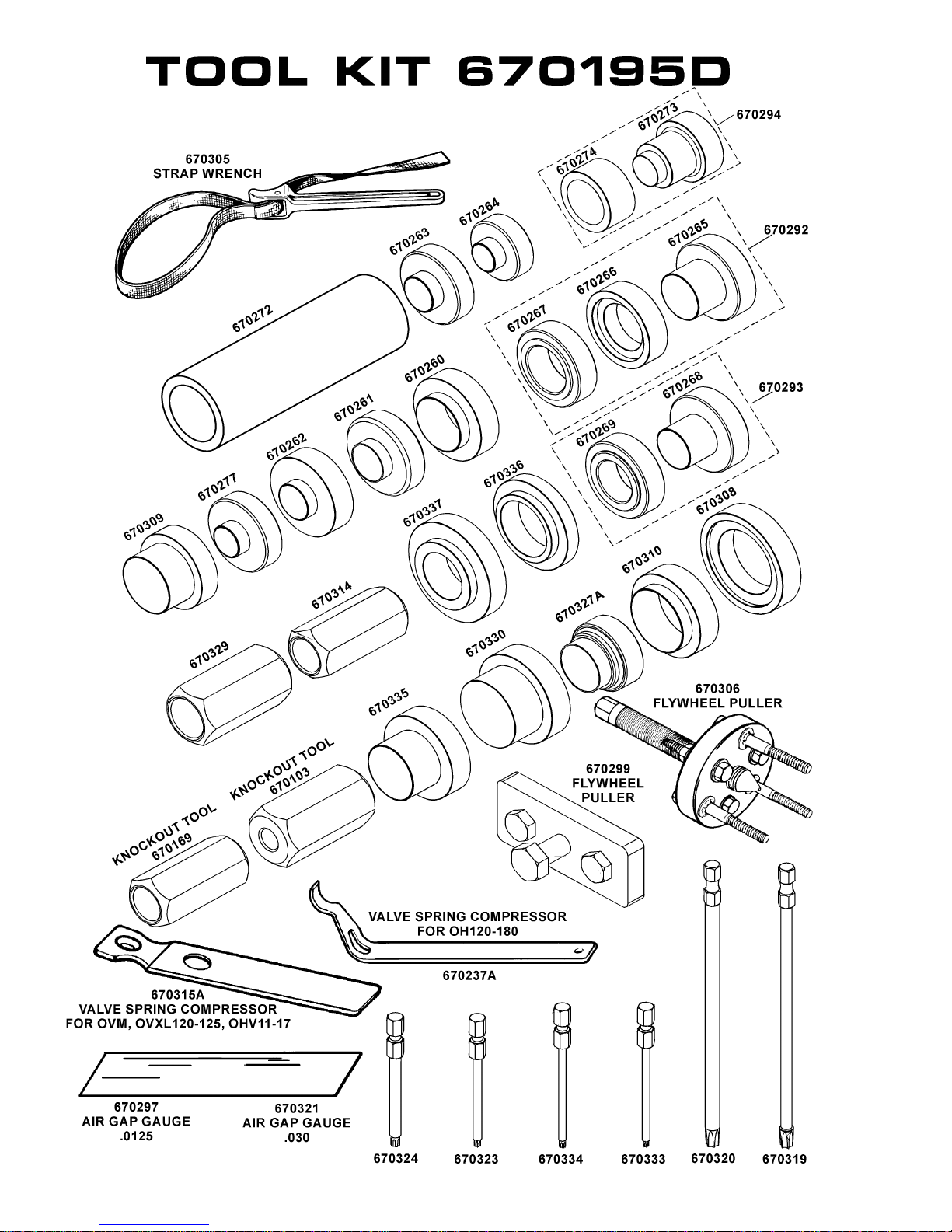
64
Page 68
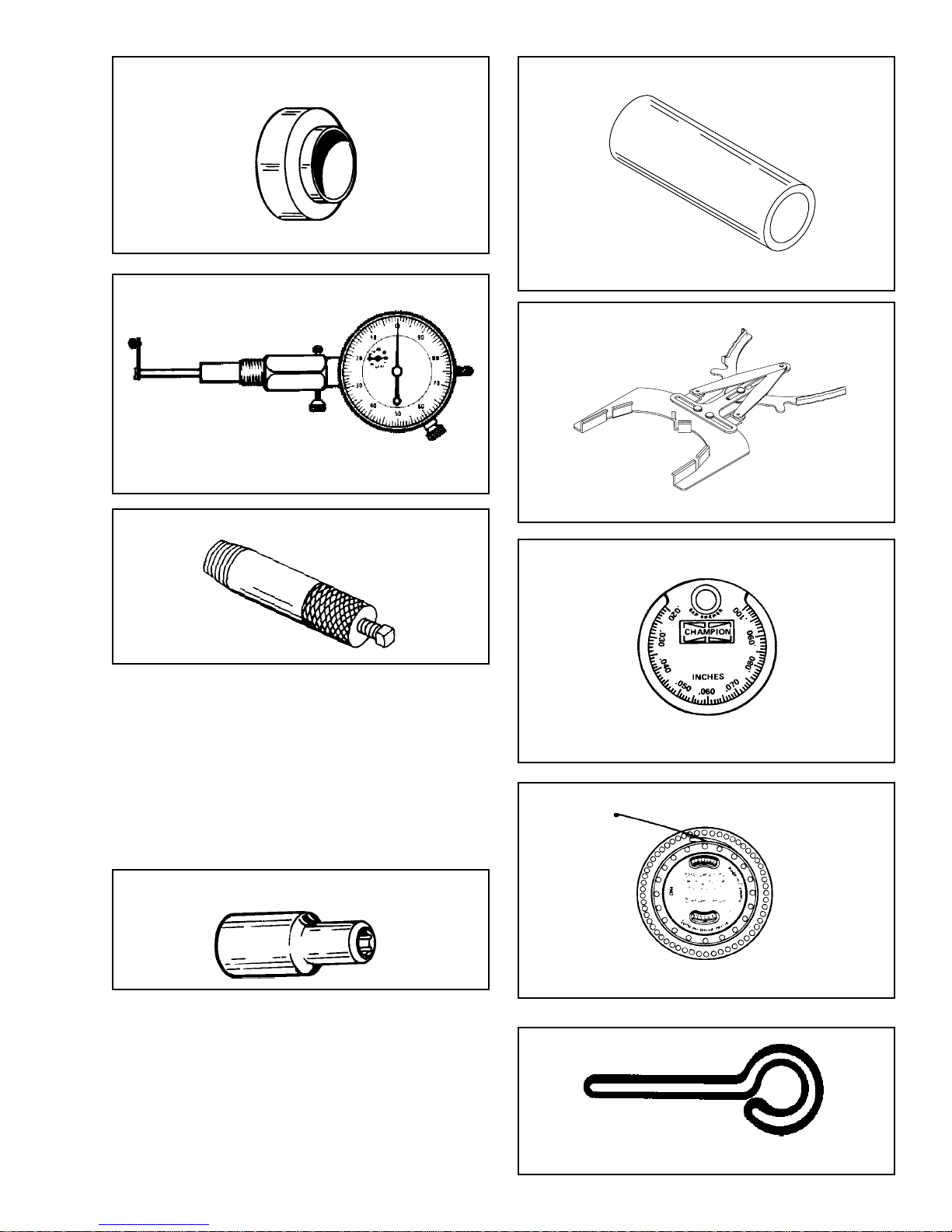
OIL SEAL DRIVER - PROTECTOR
DIAL INDICATOR
Extra Tips:
Large Head No. 670250
Thin Head No. 670249
Leg and Screw No. 670296
No. 670241 - Dial Indicator.
BALL BEARING DRIVER
No. 670258
PISTON RING EXPANDER
OIL SEAL REMOVER
No. 670286. Used on P.T.O. end of single cylinder
outboards with one piece oil seals. Includes tool No.
670285 and center screw.
No. 670291. Used on magneto end of all two cycle
engines with one piece oil seals and P.T.O. end of
1600 series. Includes tool No. 670280 and center screw.
No. 670257. Used on 2 cycle connecting rod screws.
No. 670307. Used on 590556 electric starter mounting
screws.
TORX® E-6 SOCKET
No. 670257
TORX® E-8 SOCKET
No. 670307
No. 670117 - Piston ring expander
TAPER GAP GAUGE
No. 670256 - Taper Gap Gauge
VIBRATION TACHOMETER
No. 670156 - Vibration tachometer.
No. 670298 - Aligning Pin
65
 Loading...